manualdh96cpp eng rev b · dh96-cpp kyz dh96-cpp wh wh ram dh96-cpp ... disconnect its load when...
TRANSCRIPT

PageChapter 1
Device information
Chapter 2
Chapter 3
Introduction 234
Dimensions 5
1213131415161820
Technical specificationsSafety warnings
Input typesWiring diagramsPlug-in cardsModification of the auxiliary voltage
Integration typesDemand controlVariables to visualizeKeyboard functionsProgramming introductionDevice configurationRelays control by levelForecast control of the relays
Installation and startup
Programming
68
1011
Index
Page 1
Ind
ex
PN: 430025003 revB
In the industry, a higher powerconsumption than the contracted one canlead to severe penalties. Often there arepower peaks produced by loadscoincidence that normally do not work in asimultaneously. In order to avoidpenalties, one solution would beincreasing the contracted poweraccording to the maximum registeredpeak, but on contrast this will force to paya higher power than it is really needed.
Another solution will be avoiding theconsumption peaks through a vigilanceelement that advise us of the risk situationor it can disconnect certain dispensableloads ( air conditioning, compressors,lighting...)
The new has beendesigned especially for the control ofpower demand through energy pulses. Bymeans of this equipment, the consumedpower during an integration period can becontrolled, depending on the energypulses that arrive to the energy meterfrom the utility.
To achieve this the hasup to 4 relays to connect and disconnectthe required loads in the most optimumway or activating an alarm that informsus about this situation.
The equipment calculates the energydemand, peak, its medium value, andconsumed. The peak and mediumdemand values as well as consumedare saved in a non-volatile , avoidingthis way its lost when the auxiliary supplydrops
The instrument has 4 digitsand 8 indication red colour leds. Theequipment parameters are configurableby means of 4 frontal keys.
DH96-CPP
KYZ
DH96-CPP
Wh
WhRAM
DH96-CPP
The has been designed tooffer a wide range of features andperformance qualities in a compact and atthe same time robust equipment thatallows to work in industrial atmospheresunder all requirements of applicablestandards.
Instruments of Series have beentested in laboratories, checked inindustrial environments, and havesuccessfully passed the most rigoroustests involving ambient conditions,electrical noises, electromagneticdisturbances, mechanical vibrations,etc...
The instrument has an additionalcommunications card that
whenever it is required can beincorporated in the device.
Through this card and by means ofprotocol, mode, we will be
able to:
Check the relays state, connect anddisconnect them whenever is needed.Read all measuring parameters:demand, totalizers, peak and mediumvalues, and reset them.Visualize and modify the programmingparameters.
MODBUS communications protocol.Instrument address selection.Communication speed selection 1200,4800, 9600 and 19200 bits/s.Parity selection: even, odd or without.Stop bits selection: 1 or 2.
DH96-CPP
DH96
Expansion options
RS232/485
MODBUS RTU
Card with RS232/485 output
�
�
�
�
�
�
�
�
Page 2
IntroductionC
ha
pte
r1
De
vic
ein
form
ati
on

Auxiliary supply:
Display :
Input circuit:
Isolation:
Environmental conditions
General characteristics
Relays features 1 single contact
Design standards:
IEC 1010 / IEC 348 / IEC 664 / EN50081-2 / EN50082-2 /ANSI C12.5-1978/ UL508/C22.2 No 14 / VDE0435
Rated value: 115V or 230 V a.c. / 24 or 48 V a.c.(-15 %, +20 %)
Frequency range: 45 to 65 HzBurden: 4 VA (without optional card)
7 VA (maximum burden)
7 segments14 mm high 4 digitsHi-efficacy red colourOverrange indication "----"8 indication LEDProgrammable decimal point
Free contact:Vc 5 VRc 3,9 k
TTL / 24V:Rc 47 kLogic Level 0 < 2 VLogic Level 1 > 3 V
NPN or PNP sensor:Rc 2 kLogic Level 0 < 2 VLogic Level 1 > 3 V
Between the input circuit, the measuring circuit and the output measure-relay, RS 485 /232Test voltage: 3 kV RMS 50 Hz during 1 minPulses test: 4 kV (1.2/50 µs)
:
Storage temperature: -40 ºC to +70 ºCOperation temperature: -10 ºC to +65 ºC
:
Dimensions: 96 x 48 x 138 mmWeight: 550 gCase material: ABS V0, anthracite greyProtection degree: Frontal: IP 54
IP 65 with frontal protectCase: IP 20Terminal: IP20
:
Rated A.C. current : 5 AMaximum A.C. current: 250 V a.c. 50 HzMaximum resistance load: 750 VAIsolation resistance 500 V: > 1000 MContact-coil isolation: 2000 V c.a.Contact-contact isolation: 750 V c.a.Mechanical endurance: > 20.000.000 operations.Electrical endurance: > 30.000 operations at 5 A. and 250 V
�
�
�
�
Page 3
Ch
ap
ter
1D
ev
ice
info
rma
tio
n
Technical specifications

Information and warning texts
Installation
¡Warning!
The DH96 meets protection class I:
It is provided with earth terminal.The case is not dangerous to tactiletouching (isolation material)Screws of terminals are notaccessible for human appendix.
This instrument has been designedand tested to meet IEC348 standard andis supplied in proper conditions. Thismanual contains information andwarnings that the user should respect inorder to guarantee a proper operation ofall instrument's functions and keep itssafety conditions.
The instrument is for indoor use. Itcould be occasionally subjected totemperatures between -10 ºC and +75 ºCkeeping its safety conditions.
The instrument must not be poweredand used until being correctly assembledon the board.
Before powering the instrument, itsearth terminal must be connected to asuitable protection cable.
Any interruption of the protectionconductor, either inside or outside theinstrument, or the disconnection of theprotection earth terminal might imply adangerous situation; therefore, anyintentional interruption is whollyforbidden.
�
�
�
Adjustment, spare parts andrepairing actions.
Defects and malfunction
With the instrument powered on, theterminals could be dangerous to touch andcover opening actions, may allowaccessing dangerous parts. Therefore,before any adjustment, replacement,maintenance or repairing operation iscarried out, the instrument must beswitched off from any power supply source
No adjustment, maintenance orrepairing operation should be done overthe instrument opened and powered, andif they are essential, high-qualifiedoperators must perfom them.
Check that fuses used for replacingdamaged ones match required types andrated currents. Unsuitable fuses or short-circuit fuse bases must be completelyforbidden.
When any protection failure issupposed to exist, the instrument must beput out of service. The protection can bedamage whether:
You can see visible damages.I t c a n n o t p e r f o r m p r o p e rmeasurements.Storage conditions were not thesuitable ones.Any damage in transport happened.
�
�
�
�
Safety warnings
Page 4
Ch
ap
ter
1D
ev
ice
info
rma
tio
n

Hold
ing
pie
ce
Ch
ap
ter
2In
sta
lla
tio
na
nd
sta
rtu
p
Dimensions
45
92
+0
,8
+0,6
Co
rte
de
lp
ane
lC
orte
de
lp
ane
l
Page 5
Panelcut-
out
Input types
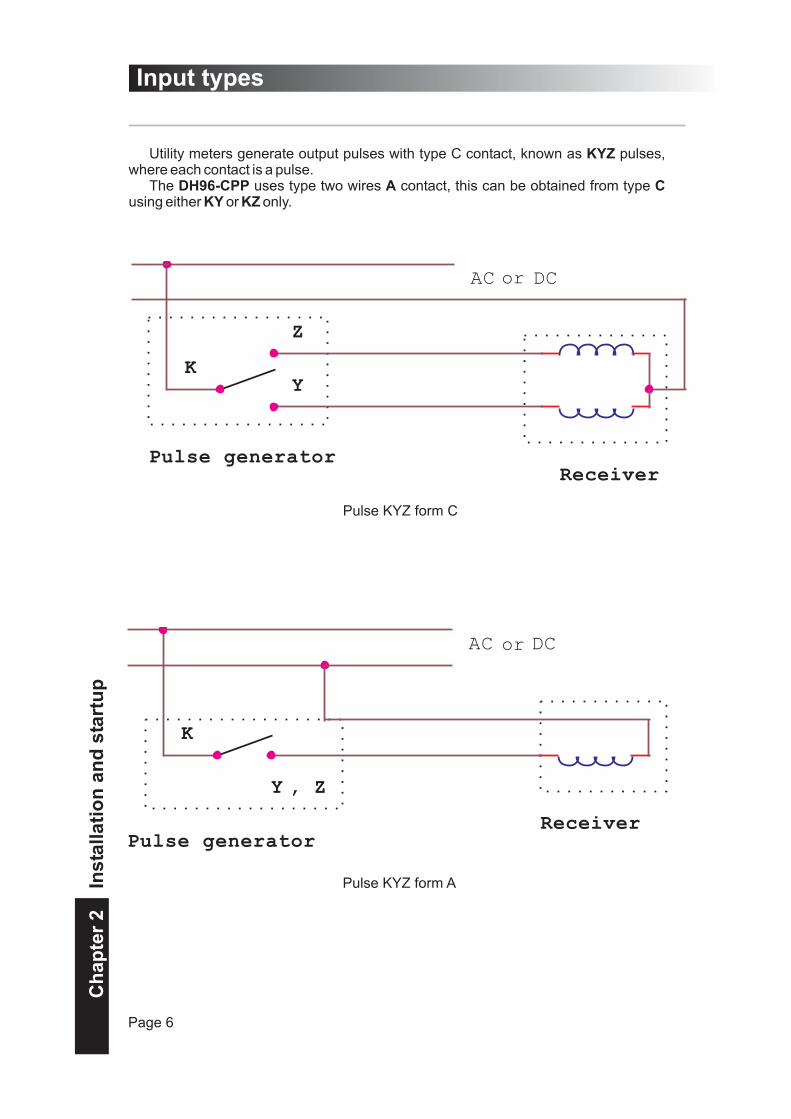
Utility meters generate output pulses with type C contact, known as pulses,where each contact is a pulse.
The uses type two wires contact, this can be obtained from typeusing either or only.
KYZ
DH96-CPP A CKY KZ
AC o DC
K
Z
Y
Pulse generatorReceiver
Pulse KYZ form C
AC o DC
K
Y
Pulse generatorReceiver
, Z
Pulse KYZ form A
Page 6
Ch
ap
ter
2In
sta
lla
tio
na
nd
sta
rtu
p
or
or

Input types
For it, the will count a pulse whenever the position of the contact should bemodified, it's means, in every change of level.
DH96-CPP
The admits, for each of his two inputs - and- the connection through:
Free potencial pulses,Pulses by level of voltage (TTL/24V),NPN or PNP sensors.
The conexion type will be selected by means of the on-board microswitches, SW. Foraccessing these microswitches the box must be opened according to indications in thepage 10
Once these microswitches have been located, select the transducer to be used justfollowing indications attached in the table.
Note: The instrument is factory shipped for the use a free potencial pulses.
DH96-CPP KYZ synchronism inputpulses
�
�
�
( ).Plug-in cards
Page 7
Ch
ap
ter
2In
sta
lla
tio
na
nd
sta
rtu
p

1
3V < level 1 < 24V
Wiring diagrams
Page 8
1.- Connection for free potential pulses,
2.- Connection for pulses by level of voltage (TTL/24V),
Ch
ap
ter
2In
sta
lla
tio
na
nd
sta
rtu
p
(AUX) 12V
(IN3) Synchronismor(IN2) KYZ P.
(IN3) Synchronismor(IN2) KYZ P.
(COM) GND

PNP
NPN
Wiring diagrams
Page 9
3.- Connection for NPN sensor
4.- Connection for PNP sensor,
Cards: Connection of relays
4 relays:
Ch
ap
ter
2In
sta
lla
tio
na
nd
sta
rtu
p
or
or

WARNING
Proceed as pictures show below:
: Insure that no incomingwire is connected to the equipment beforedoing any manipulation work on theequipment, since observed failure in theequipment can provoke equipmentdamages and even serious injury.
1) Press the case holding piece with ascrewdriver or a similar tool in order torelease the base from the rest of the case.
2) Remove the set composed by thebase and circuits by pulling the base andcarefully sliding it out.
3) Insert the card into the suitableconnector. Take care that only theconnector is pressed but not all the card.
4) Put the set composed by the baseand circuits in, again, by pushing the baseand carefully sliding it inside. When the setis totally inserted, press until the caseholding pieces are fitted into the pertinentholes.
Plug-in cards
Page 10
1)
2)
3)
4)
Ch
ap
ter
2In
sta
lla
tio
na
nd
sta
rtu
p

The instrument is manufactured to besupplied with 230 V a.c. But it is possible tochange to 115 V a.c. Following theinstructions below mentioned:
To perform this modification, open theinstrument case (see page 10 "
") thoughtfully following all(see page 4), and identify the
zone referred to picture 1.
For an auxiliary supply of 230 V onlythe jump labelled as 1 must be done (fig. 2)
On the contrary, if an auxiliary supply of115 V is required, only jumps labelled as 2and 3 must be done (fig. 3).
plug-incards safetywarnings
Modification of auxiliary voltage
Page 11
fig. 1
fig. 3
fig.2
Ch
ap
ter
2In
sta
lla
tio
na
nd
sta
rtu
p

The can be programmed inorder to operate in 4 different integrationmodes:
1 - Synchronised with the utilitymaximeter, through synchronism pulsesthat are given in each period initiation( ).
2 - Synchronised with the utilitymaximeter, by means of synchronismpulse. ( ). From thispulse, the equipment calculates the startsand ends of each period based in aninternal clock. When a new pulse isreceived, it will be re-adjusted and it will besynchronised again.( It is recommendedto receive one synchronism pulse each 24hours.)
3 - Without synchronism with the utilitymaximeter, using a sliding window( ).
4 - Without synchronism with themaximeter, using a sliding window andsimulating the response of the thermalexponential function of the mechanicalmeters ( ).
DH96-CPP
Block demand Pulse
Block demand Time
Rolling demand
Thermal demand
Example:
ThermalDH96-CPP
Following the graph you can observethe behaviour of the device in the 4operation modes, for an integration periodof 5 minutes.
For synchronised operation mode (block demand pulse and block demandtime ) and Rolling (sliding window) thedevice will reach up to the maximum valueof the demand, in this case 36 kW, at theend of the integration period (5 minutes).
For operation mode, thewill get up to 90% of the
maximum demand value at the 5 minutes,and up to 99,9 % at 10 minutes.
Demand
0
6
12
18
24
30
36
42
0 100 200 300 400 500 600
time (second)
Kw
block pulse, block time, rolling thermal
Integration types
Page 12
Ch
ap
ter
3P
rog
ram
min
g

Demand Control
This device has two operation modesin order to getting the relays control:
, for Rolling,Thermal, Block demand pulse and Blockdemand Time operation modes.
, for Block demandpulse and Block demand Time operationmodes.
If the option of hasbeen chosen, we will program the valuefor each one of the relays that we want todisconnect its load when the demandvalue exceeds it. In this option, we will beable to introduce delays in the relay'sdisconnection, in the connection,hysteresy, latch option, failure security...for each of the programmed loads.
-Control by level
-Predictive control
control by level
Variables to visualize
The DH96-CPP is based on amicroprocessor, that calculates from KYZpulses the following parameters:
- (kW), in any of the 4calculation programmable modes
, it is themaximum value of the demand it has beenreached.
- , it isthe average of demands reached inthelast 32 integration periods.
This value is visualized for thesynchronised operation modes only. For a15 minutes of integration period it will bethe average of the lat 8 hours.
- . It exists threetotalizers than can count up to999,999,999 Wh.
Energy demand
Peak value of the demand
Medium value of the demand
Consumed Wh
-
In the , connectionand disconnection of the loads will bemade by means of one algorithm thatoptimises the number of manoeuvres andguarantees the contracted power cannotbe exceeded, provided that theprogrammed values are the ones thatreally are in the installation. In order toachieve this, we must program thecontracted power from the utility and theindividual power of each load that we willlink to the .
If the 4 existing relays are not used, the4 relay acts like an alarm, it activates itselfwhen al l the loads have beendisconnected.
predictive control
DH96-CPP
th
Peak and medium demand values aswell as the totalizers are saved in anon-volatile memory, that can bedisplayed whenever it is required,avoiding the lost of the same if theauxiliary supply drops. This system doesnot require any maintenance.
totalizers, medium and peakvalues, can be reseted whenever it isneeded.
WhRAM
Wh
Ch
ap
ter
3P
rog
ram
min
g
Page 13
Demand control, Variables to visualize
Programming
Visualization
Totalizers visualization /peak and medium values
Totalizer's / peak andmedium values reset
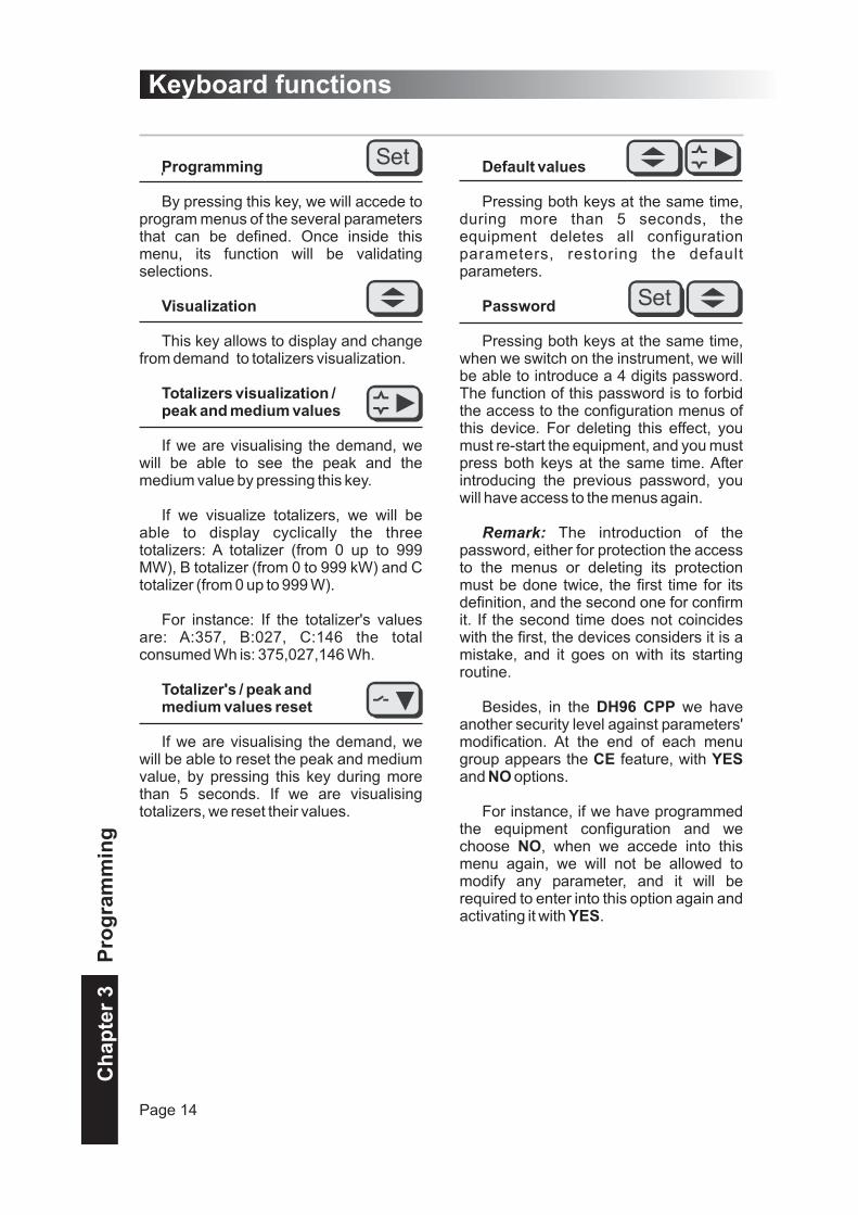
By pressing this key, we will accede toprogram menus of the several parametersthat can be defined. Once inside thismenu, its function will be validatingselections.
This key allows to display and changefrom demand to totalizers visualization.
If we are visualising the demand, wewill be able to see the peak and themedium value by pressing this key.
If we visualize totalizers, we will beable to display cyclically the threetotalizers: A totalizer (from 0 up to 999MW), B totalizer (from 0 to 999 kW) and Ctotalizer (from 0 up to 999 W).
For instance: If the totalizer's valuesare: A:357, B:027, C:146 the totalconsumed Wh is: 375,027,146 Wh.
If we are visualising the demand, wewill be able to reset the peak and mediumvalue, by pressing this key during morethan 5 seconds. If we are visualisingtotalizers, we reset their values.
Default values
Password
DH96 CPP
CE YESNO
NO
YES
Pressing both keys at the same time,during more than 5 seconds, theequipment deletes all configurationparameters, restoring the defaultparameters.
Pressing both keys at the same time,when we switch on the instrument, we willbe able to introduce a 4 digits password.The function of this password is to forbidthe access to the configuration menus ofthis device. For deleting this effect, youmust re-start the equipment, and you mustpress both keys at the same time. Afterintroducing the previous password, youwill have access to the menus again.
The introduction of thepassword, either for protection the accessto the menus or deleting its protectionmust be done twice, the first time for itsdefinition, and the second one for confirmit. If the second time does not coincideswith the first, the devices considers it is amistake, and it goes on with its startingroutine.
Besides, in the we haveanother security level against parameters'modification. At the end of each menugroup appears the feature, withand options.
For instance, if we have programmedthe equipment configuration and wechoose , when we accede into thismenu again, we will not be allowed tomodify any parameter, and it will berequired to enter into this option again andactivating it with .
Remark:
Keyboard functions
Page 14
Ch
ap
ter
3P
rog
ram
min
g

DH96 CPP configuration is easy,intuitive and makes the user familiar with it, allowing whenever he requires, withoutusing the manual, the modification of thedifferent programming instrument'sfeatures.
By means of a program menu,disposed in a tree mode, he can programall the equipment's operation in a logicalway.
The steps to follow are:
1) Firstly the user will program thedevice's configuration, where he will beable to settle: the energy that belongs toeach pulse, operation type, integrationperiod, decimal point position, andoperation mode.
2) Following on, if there is a relayscards and we have programmed thedevice in operation mode, we willchoose the control type of the relays:relays control by level or predictivecontrol.
3) Finally, we will program the relays'configuration Menu that appears dependson previous selection.
Block
Programming introduction
Page 15
Ch
ap
ter
3P
rog
ram
min
g

Device configuration
Page 16
Ch
ap
ter
3P
rog
ram
min
g

Programming of one value
NOTECE
YES
:To step from one digit (4 digits) to another, press the following keyTo modify the value of the selected digit press repeatedly the keyBy means of the two keys we will define completely the 4 digits of the value.
:If you see that it is impossible to change these values, go to the option and checkthat it is programmed with ( ).To validate the values, remember that the key … should be pressed repeatedly, untilyou arrive to the measured value.
Energy pulsesThe energy value in Wh belonging to each KYZ pulse is introduced.
Integration type
Integration period
Decimal point
Working modemaster
slave
Configuration enabled
Relay control
(
The integration type of the device is determined in this section :
Synchronised with the utility's maximeter,
-through synchronism pulses that are given in eachperiod start.(Block demand pulse)-by means of a synchronism pulse.(Block demandtime)
Without synchronism, using a sliding window.
Without synchronization, using a sliding window and simulatingthe response of the thermal demand (exponential).
Here you are introducing the integration period in minutes (from 1 to 60). In thethermal mode, it is the period in which we want to have the 90% of the finalvalue.
We select the position of the decimal point to display the instantaneousdemand.. Pressing the ...... key we are varying the position of the decimalpoint.
We select the working mode of the DH96, in mode the unit iscontrolling the relays, in mode the user controls the relays by modbus.
If the user programs the device as (No) it disables the modification of theprevious parameters and as (Yes) it enables the modification.
This option appears only if we have programmed the synchronization modeor ).
The device has two working modes to control the relays:
control by level,
control by forecast.
The menu to configure the relays depends on this selection.
block demand pulse block demand time
Device configuration
Page 17
Ch
ap
ter
3P
rog
ram
min
g

Relays control by level
Page 18
Ch
ap
ter
3P
rog
ram
min
g
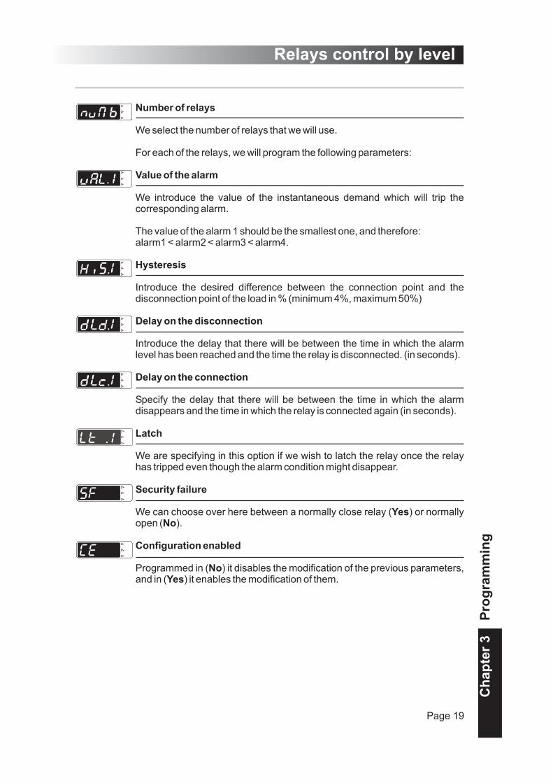
Number of relays
Value of the alarm
Hysteresis
Delay on the disconnection
Delay on the connection
Latch
Security failure
YesNo
Configuration enabled
NoYes
We select the number of relays that we will use.
For each of the relays, we will program the following parameters:
We introduce the value of the instantaneous demand which will trip thecorresponding alarm.
The value of the alarm 1 should be the smallest one, and therefore:alarm1 < alarm2 < alarm3 < alarm4.
Introduce the desired difference between the connection point and thedisconnection point of the load in % (minimum 4%, maximum 50%)
Introduce the delay that there will be between the time in which the alarmlevel has been reached and the time the relay is disconnected. (in seconds).
Specify the delay that there will be between the time in which the alarmdisappears and the time in which the relay is connected again (in seconds).
We are specifying in this option if we wish to latch the relay once the relayhas tripped even though the alarm condition might disappear.
We can choose over here between a normally close relay ( ) or normallyopen ( ).
Programmed in ( ) it disables the modification of the previous parameters,and in ( ) it enables the modification of them.
Relays control by level
Page 19
Ch
ap
ter
3P
rog
ram
min
g

Forecast control of the relays
Page 20
Ch
ap
ter
3P
rog
ram
min
g

Contracted power
Number of relays
The delay in the connection
Type of connection / disconnection of the relays)
cyclical
linear,
Transient time
Power
Security failure
YesNo
Configuration enables
NoYes
We introduce the value of the contracted maximum demand with the utility(in kW)
We select the number of relays that we will use.
Specify the delay that there will be between the time in which the alarmdisappears and the time in which the relay is connected again (in seconds).
We can select among the two different types of connection / disconnection.
- , where we disconnect first the relays that have beenconnected for a longer time
- where the connection and disconnection is made bypriorities. ( the relay 1 is the first one to be disconnected).
Depending on the load on the installation, we can have transient quickvariations on the power (for example installations with a lot of inductive load)but which should not cause an inmediate action by the controller. By meansof the transient time, we can adjust the response time of the controller to thecharacteristics of the installation.( in seconds).
For each of the relays, we introduce the power that each of the relayscontrols (in kW).
We can choose over here between a normally close relay ( ) or normallyopen ( ).
Programmed in ( ) it disables the modification of the previous parameters,and in ( ) it enables the modification of them.
Forecast control of the relays
Page 21
Ch
ap
ter
3P
rog
ram
min
g

. . . . . . . . . . . . . . . . . . . . . . . . . . . . . . . . . . . . . . . . . . . . . . . . . . . . . . . . . . . . . . . . . . . . .
. . . . . . . . . . . . . . . . . . . . . . . . . . . . . . . . . . . . . . . . . . . . . . . . . . . . . . . . . . . . . . . . . . . . .
. . . . . . . . . . . . . . . . . . . . . . . . . . . . . . . . . . . . . . . . . . . . . . . . . . . . . . . . . . . . . . . . . . . . .
. . . . . . . . . . . . . . . . . . . . . . . . . . . . . . . . . . . . . . . . . . . . . . . . . . . . . . . . . . . . . . . . . . . . .
. . . . . . . . . . . . . . . . . . . . . . . . . . . . . . . . . . . . . . . . . . . . . . . . . . . . . . . . . . . . . . . . . . . . .
. . . . . . . . . . . . . . . . . . . . . . . . . . . . . . . . . . . . . . . . . . . . . . . . . . . . . . . . . . . . . . . . . . . . .
. . . . . . . . . . . . . . . . . . . . . . . . . . . . . . . . . . . . . . . . . . . . . . . . . . . . . . . . . . . . . . . . . . . . .
. . . . . . . . . . . . . . . . . . . . . . . . . . . . . . . . . . . . . . . . . . . . . . . . . . . . . . . . . . . . . . . . . . . . .
. . . . . . . . . . . . . . . . . . . . . . . . . . . . . . . . . . . . . . . . . . . . . . . . . . . . . . . . . . . . . . . . . . . . .
. . . . . . . . . . . . . . . . . . . . . . . . . . . . . . . . . . . . . . . . . . . . . . . . . . . . . . . . . . . . . . . . . . . . .
. . . . . . . . . . . . . . . . . . . . . . . . . . . . . . . . . . . . . . . . . . . . . . . . . . . . . . . . . . . . . . . . . . . . .
. . . . . . . . . . . . . . . . . . . . . . . . . . . . . . . . . . . . . . . . . . . . . . . . . . . . . . . . . . . . . . . . . . . . .
. . . . . . . . . . . . . . . . . . . . . . . . . . . . . . . . . . . . . . . . . . . . . . . . . . . . . . . . . . . . . . . . . . . . .
. . . . . . . . . . . . . . . . . . . . . . . . . . . . . . . . . . . . . . . . . . . . . . . . . . . . . . . . . . . . . . . . . . . . .
. . . . . . . . . . . . . . . . . . . . . . . . . . . . . . . . . . . . . . . . . . . . . . . . . . . . . . . . . . . . . . . . . . . . .
. . . . . . . . . . . . . . . . . . . . . . . . . . . . . . . . . . . . . . . . . . . . . . . . . . . . . . . . . . . . . . . . . . . . .
. . . . . . . . . . . . . . . . . . . . . . . . . . . . . . . . . . . . . . . . . . . . . . . . . . . . . . . . . . . . . . . . . . . . .
. . . . . . . . . . . . . . . . . . . . . . . . . . . . . . . . . . . . . . . . . . . . . . . . . . . . . . . . . . . . . . . . . . . . .
. . . . . . . . . . . . . . . . . . . . . . . . . . . . . . . . . . . . . . . . . . . . . . . . . . . . . . . . . . . . . . . . . . . . .
. . . . . . . . . . . . . . . . . . . . . . . . . . . . . . . . . . . . . . . . . . . . . . . . . . . . . . . . . . . . . . . . . . . . .
. . . . . . . . . . . . . . . . . . . . . . . . . . . . . . . . . . . . . . . . . . . . . . . . . . . . . . . . . . . . . . . . . . . . .
. . . . . . . . . . . . . . . . . . . . . . . . . . . . . . . . . . . . . . . . . . . . . . . . . . . . . . . . . . . . . . . . . . . . .
. . . . . . . . . . . . . . . . . . . . . . . . . . . . . . . . . . . . . . . . . . . . . . . . . . . . . . . . . . . . . . . . . . . . .
. . . . . . . . . . . . . . . . . . . . . . . . . . . . . . . . . . . . . . . . . . . . . . . . . . . . . . . . . . . . . . . . . . . . .
. . . . . . . . . . . . . . . . . . . . . . . . . . . . . . . . . . . . . . . . . . . . . . . . . . . . . . . . . . . . . . . . . . . . .
. . . . . . . . . . . . . . . . . . . . . . . . . . . . . . . . . . . . . . . . . . . . . . . . . . . . . . . . . . . . . . . . . . . . .
. . . . . . . . . . . . . . . . . . . . . . . . . . . . . . . . . . . . . . . . . . . . . . . . . . . . . . . . . . . . . . . . . . . . .
. . . . . . . . . . . . . . . . . . . . . . . . . . . . . . . . . . . . . . . . . . . . . . . . . . . . . . . . . . . . . . . . . . . . .
. . . . . . . . . . . . . . . . . . . . . . . . . . . . . . . . . . . . . . . . . . . . . . . . . . . . . . . . . . . . . . . . . . . . .
. . . . . . . . . . . . . . . . . . . . . . . . . . . . . . . . . . . . . . . . . . . . . . . . . . . . . . . . . . . . . . . . . . . . .
. . . . . . . . . . . . . . . . . . . . . . . . . . . . . . . . . . . . . . . . . . . . . . . . . . . . . . . . . . . . . . . . . . . . .
. . . . . . . . . . . . . . . . . . . . . . . . . . . . . . . . . . . . . . . . . . . . . . . . . . . . . . . . . . . . . . . . . . . . .
. . . . . . . . . . . . . . . . . . . . . . . . . . . . . . . . . . . . . . . . . . . . . . . . . . . . . . . . . . . . . . . . . . . . .
. . . . . . . . . . . . . . . . . . . . . . . . . . . . . . . . . . . . . . . . . . . . . . . . . . . . . . . . . . . . . . . . . . . . .
. . . . . . . . . . . . . . . . . . . . . . . . . . . . . . . . . . . . . . . . . . . . . . . . . . . . . . . . . . . . . . . . . . . . .
. . . . . . . . . . . . . . . . . . . . . . . . . . . . . . . . . . . . . . . . . . . . . . . . . . . . . . . . . . . . . . . . . . . . .
No
tes
Notes
Page 22