manual/electric portable patient lift and ... portable patient lift and slings owner's...
TRANSCRIPT

MANUAL/ELECTRICPORTABLE PATIENT LIFT
and SLINGS
OWNER'SINSTALLATION AND OPERATING INSTRUCTIONS

2
SPECIAL NOTES
SPECIAL NOTES
SPECIAL
NOTES
WARNINGDO NOT OPERATE THIS EQUIPMENT WITHOUT FIRST
READING AND UNDERSTANDING THIS MANUAL. IF YOUARE UNABLE TO UNDERSTAND THE WARNINGS,
CAUTIONS AND INSTRUCTIONS; CONTACT AHEALTHCARE PROFESSIONAL (DOCTOR-THERAPIST)
BEFORE ATTEMPTING TO USE THIS EQUIPMENT -OTHERWISE INJURY OR DAMAGE MAY RESULT.
SAVE THESE INSTRUCTIONSAND
KEEP WITH PATIENT LIFT AT ALL TIMES.
NOTICEThe information contained in this document is subject to change withoutnotice.
WARNING notices as used in this manual apply to hazards or unsafepractices which could result in serious bodily harm.
CAUTION notices as used in this manual apply to hazards or unsafepractices which could result in minor personal injury or property damage.
NOTES highlight procedures and contain information which assist theoperator in understanding the information contained in this manual.
RADIO FREQUENCY INTERFERENCE
Most electronic equipment is influenced by Radio Frequency Interference (RFI).CAUTION should be exercised with regard to the use of portablecommunication equipment in the area around such equipment. If RFI causeserratic behavior, PUSH the EMERGENCY STOP BUTTON DOWN (ê) IMMEDI-ATELY. DO NOT disengage the Emergency Stop Button while transmission is inprogress.
MAINTENANCEMaintenance MUST be performed ONLY by qualified personnel.

3
TABLE OF CONTENTS SPECIAL NOTES ............................................. 2 SAFETY SUMMARY ......................................... 4 SPECIFICATIONS ............................................ 5 FEATURES ....................................................... 6
HANDLING PROCEDURES ............................. 8 Shipping and Transportation Instructions ......... 8
Unpacking ....................................................... 8Inspection ........................................................ 8Storage............................................................ 8
ASSEMBLY....................................................... 9 Assembly of the Patient Lift .............................. 9
Unpacking the Patient Lift ............................... 9Assembling the Mast to the Base ................... 9Assembling the Manual/Hydraulic Pump to
the Boom .................................................... 10Assembling the Electric Actuator to the
Boom .......................................................... 10Shifter Handle Installation ............................. 11
CONVERSION FROM A MANUAL TO ANELECTRIC LIFT ......................................... 12
Disassembly/Assembly ................................... 12Removing the Manual/Hydraulic Pump
Assembly .................................................... 12Assembly of the Electric Actuator ................. 12Attaching the Control Box to the Mast .......... 13Battery Charging ........................................... 13
ONE-PIECE CONTOUR SLINGS ................... 15 Model No. 9746 Hammock and Model No.
9747 Hammock w/Commode Opening ......... 15Fabric ............................................................ 15Body ............................................................. 15
Positioning the Model No. 9746 Hammock orModel No. 9747 Hammock w/CommodeOpening......................................................... 16
Positioning the Patient on the Sling with orwithout Commode Opening .......................... 16
MODEL NO. 9742 UNIVERSAL DELUXESLING ............................................................ 18
Positioning the Patient in the Model No. 9742Universal Deluxe Sling .................................. 18
OPERATION ................................................... 20 Operating the Patient Lift ................................ 20
To Close/Open the Legs of the BaseAssembly .................................................... 20
Raising/Lowering Manual/Hydraulic Lift ........ 20Raising the Lift ........................................... 20Lowering the Lift ......................................... 21
TABLE
OF
CONTENTS
OPERATION (Cont.)Raising/Lowering Electric Lift ........................ 21
Raising the Lift ........................................... 21Lowering the Lift ......................................... 21
LIFTING THE PATIENT .................................. 22 Attaching the Slings to the Patient Lift ............ 22 Lifting/Moving the Patient ................................ 23
TRANSFERRING PATIENT FOR USE OFTHE BATHROOM FACILITIES .................. 25
Transferring Patient for Use of a CommodeChair or Standard Commode ..................... 25
Transferring to a Commode Chair ................ 25Transferring to a Standard Commode .......... 26
Transferring to a Bathing Unit...... ................... 26
TRANSFERRING TO A WHEELCHAIR ......... 27
TRANSFERRING FROM A WHEELCHAIRTO A CAR .................................................. 28
TRANSFERRING FROM A CAR TO AWHEELCHAIR .............................................. 30
TROUBLESHOOTING.................................... 31
MAINTENANCE SAFETY INSPECTIONCHECKLIST .................................................. 32
CARE AND MAINTENANCE OF YOURPATIENT LIFT ............................................ 33
Lubrication ..................................................... 33Wear and Damage ........................................ 33Cleaning ........................................................ 33Manual/Hydraulic Pump ................................ 34
Manual/Hydraulic Pump or ElectricActuator Replacement ............................. 34
Swivel Bar Replacement ............................... 35Base Adjustment ........................................... 35Shifter Handle Adjustment ............................ 36Casters .......................................................... 36
Rear Caster Replacement .......................... 36Front Caster Replacement ......................... 36Front Caster Housing Removal .................. 36
ACCESSORIES .............................................. 37Invacare 9833A Weight Module
(Digital Scale) ............................................. 37
LIMITED WARRANTY .................................... 39
TABLE OF CONTENTS

4
SAFETY SUMMARY
SAFETY SUMMARY
WARNINGCheck all parts for shipping damage before using. In case of damage, DO NOT use the equipment. Contact theDealer for further instructions.
The Invacare patient lift is NOT a transport device. It is intended to transfer an individual from one restingsurface to another (such as a bed to a wheelchair). Moving a person suspended in a sling over ANY distanceis NOT recommended.
DO NOT attempt any transfer without approval of the patient’s physician, nurse or medical assistant.Thoroughly read the instructions in this Owner’s Manual, observe a trained team of experts perform the liftingprocedures and then perform the entire lift procedure several times with proper supervision and a capableindividual acting as a patient.
Use common sense in all lifts. Special care MUST BE taken with people with disabilities who cannot cooperatewhile being lifted. Use restraint straps if necessary.
Invacare slings and patient lift accessories are specifically designed to be used in conjunction with Invacarepatient lifts. Slings and accessories designed by other manufacturers are not to be utilized as a component ofInvacare’s patient lift system. Use of these products is prohibited and will void Invacare’s patient lift warranty.Use only genuine Invacare slings and lift accessories to maintain patient safety and product utility.
Use a sling that is recommended by the individual’s doctor, nurse or medical assistant for the comfort andsafety of the individual being lifted.
DO NOT use any kind of plastic back incontinence pad or seating cushion between the patient and slingmaterial that may cause the patient to slide out of the sling during transferring.
When using an adjustable base lift, the legs MUST BE in the maximum OPENED/LOCKED position BEFORElifting the patient.
Before transferring a patient from a stationary object (wheelchair, commode or bed), slightly raise the patientoff the stationary object and check that all sling attachments are secure. If any attachment is not correct, lowerthe patient and correct the problem, then raise the patient and check again.
During transfer, with patient suspended in a sling attached to the lift, DO NOT roll caster base over objects suchas carpet, raised carpet bindings, door frames, or any uneven surfaces or obstacles that would create animbalance of the patient lift and could cause the patient lift to tip over. Use steering handles on the mast at ALLtimes to push or pull the patient lift.
Invacare does NOT recommend locking of the rear casters of the patient lift when lifting an individual.Doing so could cause the lift to tip and endanger the patient and assistants. Invacare DOES recommendthat the rear casters be left UNLOCKED during lifting procedures to allow the patient lift to stabilize itselfwhen the patient is initially lifted from a chair, bed or any stationary object.
After the first 12 months of operation, inspect the swivel bar and the eye of the boom (to which it attaches) forwear. If the metal is worn, the parts MUST be replaced. Make this inspection every three (3) months thereafter.
The hydraulic/electric pump is sealed at the factory and if service is required, the pump unit MUST BE returnedto the factory for repair. DO NOT attempt to open the hydraulic/electric pump or obtain local service as this willVOID the warranty and may result in damage and a costly repair. Consult your Dealer or Invacare for furtherinformation.
Casters and axle bolts require inspection every six (6) months to check for tightness and wear.
Regular maintenance of patient lifts and accessories is necessary to assure proper operation.
DO NOT exceed maximum weight limitation of the patient lift. The suggested weight limitation will vary from300 lbs. for the Electric Lift to 375 lbs. for the Manual (Hydraulic) Lift depending on the type of patient liftpurchased.
SAFETY
SUMMARY

5
SPECIFICATIONS
SPECIFICATIONS
9700Manual / Hydraulic
SPECIFICATIONS
9701Electric
Height at Sling Hook-up- MAX.:
Height at Sling Hook-up- MIN.:
Base Width OPEN:Base Width CLOSED:
Base Height (Clearance):
Base Length:
Caster Size (FRONT/REAR):
Folded Height:
Sling Options:
Weight Capacity:
Weight IN Carton:
Weight OUT of Carton:
Battery:
Charger Input:
Charger Output:
Accessories:
Audible Low Battery Alarm:
Motor Safety Devices:
* Approx. Lifts per Charge:
Warranty Pump/Electronics:
67.5-inches
18.5-inches
42.0-inches24.5-inches
3.5-inches
42.0-inches
2.0-inches/5.0-inches
16.5-inches
3-Styles
375 lbs.
96 lbs.
78 lbs.
N/A
N/A
N/A
Digital Scale, Quick Fold Kit
N/A
N/A
N/A
1 Year
66-inches
17-inches
42.0-inches24.5-inches
3.5-inches
42.0-inches
2.0-inches/5.0-inches
16.5-inches
3-Styles
300 lbs.
92 lbs.
79 lbs.
2-12V Rechargeable Sealed
120V AC
24V DC
Digital Scale, Quick Fold Kit
When Recharging Needed
Automatic Stop Button
60 to 100
1 Year
NOTE: 9700K Electric Conversion Kit has the same specifications as 9701. Kit includes actuator, battery withbracket, remote control unit, recharging unit and attachment hardware.
* Varies dependent upon load and stroke.
9742 9746 9747SLINGS Universal Deluxe Hammock Hammock
Padded w/Commode
Overall Length: 25-inches Back 50-inches 50-inches27-inches Leg
Overall Width: 41-inches 40-inches 40-inches
Commode Opening: N/A N/A 6-inches Wide x 12-inches Long
Accessories: 9732 Digital Scale Bracket ONLY.9770 Easy-Store Kit (Pin and Ring Assembly for quickly Disassembling Lift WITHOUT Tools).

6
FEATURES
FEATURES
MANUAL / HYDRAULIC LIFT (FIGURE 1)
Manual / Hydraulic weight limitation is 375 lbs.
Mast bolts into base. Can be separated for storage.
Operation optimizes lift capabilities. Requires lessphysical effort for raising patient.
Offset mast and boom style provides better lift path.Maximizes full travel range.
Pump handle can rotate from side-to-side forconvenience of assistant.
Range: 49.0 - inches of range allows the patient tobe picked up from a lying position on floor.
ELECTRIC LIFT (FIGURE 2)
Electric lift weight limitation is 300 lbs.
Mast bolts into base. Can be separated for storage.
Operation optimizes lift capabilities. Requires lessphysical effort for raising patient.
Offset mast and boom style provides better lift path.Maximizes full travel range.
Hand control with elongated cord for convenienceof assistant.
Range: 49.0 - inches of range allows the patient tobe picked up from a lying position on floor.
FEATURES
Sling SoldSeparately
Castered Base
Boom
Swivel Bar
HydraulicPump
PumpHandle
FIGURE 2 - ELECTRIC LIFT
Boom
Electric Actuator
HandControl
Mast
FIGURE 1 - MANUAL/HYDRAULIC LIFT
Mast
ControlValve
ShifterHandle
ControlBox
ShifterHandle
Castered Base
SwivelBar

7
FEATURES
FEATURES (Cont.)
PATIENT SLINGS
WARNINGUse a sling that is recommended by theindividual’s doctor, nurse or medical assistantfor the comfort and safety of the individualbeing lifted.
Patient slings work in conjunction with lifts tosupport the patient during lifting and transferringprocedures.
Slings attach to the lift by using the sewn-inhook-on points. Slings are adjustable.
Each sling offers reinforcing at each hook-on pointto ensure patient safety.
Each sling is constructed of durable materials whichresist deterioration from exposure to moisture orlaundering.
Model No. 9746 Hammock and Model No. 9747Hammock w/Commode Opening (FIGURE 3)
NOTE: Both slings have a headrest.
The one-piece contour slings can be used on heavyor light patients. Supports patient from head to theknees. Used for weighing, transferring or to simplifythe use of restroom facilities.
Model No. 9742 Universal Deluxe Sling(FIGURE 4)
FEATURES
Model No. 9746 Model No. 9747
FIGURE 3 - MODEL NO. 9746 HAMMOCK ANDMODEL NO. 9747 HAMMOCK w/COMMODE
OPENING SLINGS
FIGURE 4 - MODEL NO. 9742 UNIVERSALDELUXE SLING
ACCESSORIES
Model 9833 Weight Module (Digital Scale)and Adapter Bracket
375 lbs. CapacityAccurate within 0.25 gramsMeasures 4.5-inches (Height)
NOTE: Refer to Accessories Section in the backof this manual for correct operation of the Model9833 Digital Scale.
Divided leg design is best suited for high levelspinal cord injuries or patients which sling removalis more difficult. Support ranges from the upper backto beneath the thighs. Can be positioned withpatient seated. Greatly simplifies the use of restroomfacilities.
8
HANDLING PROCEDURES
SHIPPING AND TRANSPORTATIONINSTRUCTIONS (FIGURE 1)
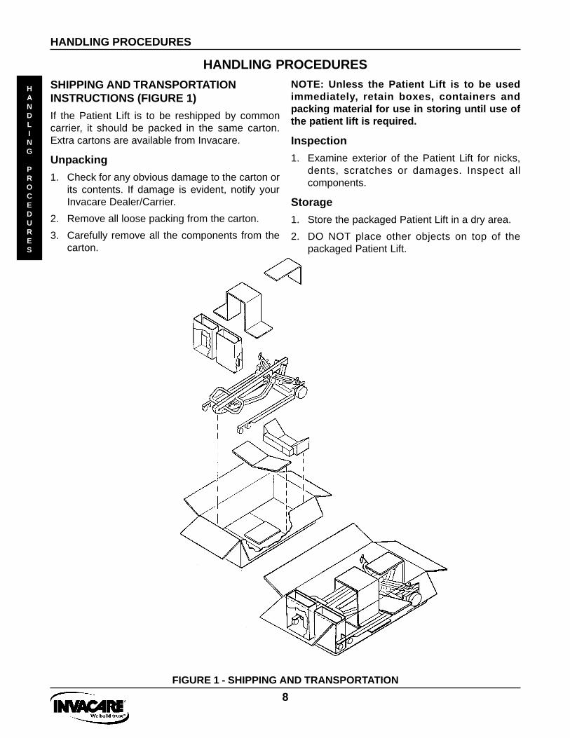
If the Patient Lift is to be reshipped by commoncarrier, it should be packed in the same carton.Extra cartons are available from Invacare.
Unpacking
1. Check for any obvious damage to the carton orits contents. If damage is evident, notify yourInvacare Dealer/Carrier.
2. Remove all loose packing from the carton.
3. Carefully remove all the components from thecarton.
NOTE: Unless the Patient Lift is to be usedimmediately, retain boxes, containers andpacking material for use in storing until use ofthe patient lift is required.
Inspection
1. Examine exterior of the Patient Lift for nicks,dents, scratches or damages. Inspect allcomponents.
Storage
1. Store the packaged Patient Lift in a dry area.
2. DO NOT place other objects on top of thepackaged Patient Lift.
HANDLING PROCEDURES
HANDLING
PROCEDURES
FIGURE 1 - SHIPPING AND TRANSPORTATION

9
ASSEMBLY
ASSEMBLY OF THE PATIENT LIFT
WARNINGUse ONLY Invacare parts in the assembly of thispatient lift. The base legs, the mast, boom, pumpassembly and the swivel bar are manufactured tospecifications that assure correct alignment of allparts for safe functional operation.
ASSEMBLY
FIGURE 4 - SECURING MAST TO BASE
1. Unpack the components from the shipping carton.
2. Cut the tie-wraps that secure swivel bar to the baseand the pump assembly to the mast (FIGURE 1).
Unpacking the Patient Lift
ASSEMBLY
AdjustmentKnob
U-shapedcut-outs
MastBushing
WARNINGThe mast may be removed from the base forstorage or transporting. Each time the mast isremoved and returned to the base, the mast MUSTbe properly secured to the base assembly.
3. Position the mast bushings into the U-shapedcut-out of the base while pushing the mast into anupright position (FIGURE 4).
4. Insert pivot bolt with washers through the base andmast bushing. Secure with nut (FIGURE 4).
5. Align adjustment knob flush with the lip of theU-shaped cut-out of the base (FIGURE 4).
NOTE: This will prevent the mast fromdisengaging from the base.
Tie-Wrap
FIGURE 1 - UNPACKING THE PATIENT LIFT
Assembling the Mast to the Base
1. Lock casters (FIGURE 2).
FIGURE 2 - LOCKING THE CASTERS
2. Remove the covers, pivot bolt, nut and washers,located at the base of the mast (FIGURE 3).
FIGURE 3 - REMOVING PIVOT BOLT
NOTE: The connection between the mast and thebase should be cleaned and coated withpetroleum jelly prior to assembly.
LOCK UNLOCK

10
ASSEMBLY (Cont.)
ASSEMBLY
Assembling the Manual / Hydraulic Pumpto the Boom (FIGURE 5)
1. Remove the covers, bolt, and nut from themounting bracket on the boom assembly.
2. Unpack the plastic bushing from the patient liftcarton.
3. Lift-up on the boom and place it on your leftshoulder.
4. Let the hydraulic pump rest on the right-side ofyour chest and rotate the shaft extension of thehydraulic pump assembly until it lines-up withthe mounting bracket holes in the boomassembly.
5. Turn the plastic bushing 90o and place over theshaft extension of the hydraulic pump.
Plastic BushingNOTE: Turn 90 o.
ASSEMBLY
WARNINGThere are two (2) silver plugs in the mountingholes next to the hydraulic pump mountingbracket on the boom. DO NOT remove thesesilver plugs and use these holes at anytime orinjury to the patient and/or assistant mayoccur (FIGURE 5).
6. Align the holes of the boom assembly mountingbracket with those of the hydraulic pump andinsert the bolt. Secure with nut.
NOTE: Be sure that the bolt is completelythrough the holes of the boom assemblymounting bracket and the manual / hydraulicpump assembly. The boom assembly will pivoteasily if the mounting hardware is alignedproperly when the boom assembly is securedto the mast. CAUTIONDO NOT overtighten the nut and bolt and bendthe mounting bracket.
MountingBracket
FIGURE 5 - ASSEMBLING THE MANUAL / HYDRAULIC PUMP TO THE BOOM
Assembling the Electric Actuator to theBoom (FIGURE 6)
1. Remove the covers, bolt, and nut from themounting bracket on the boom assembly.
2. Unpack the plastic bushing from the patient liftcarton.
3. Lift-up on the boom and place it on your leftshoulder.
NOTE: The bottom of the electric actuatorassembly will already be assembled to the mastmounting bracket.
4. Let the actuator rest on your right-side of yourchest and rotate the shaft extension of theactuator assembly until it lines-up with the mount-ing holes in the boom assembly.
5. Place the plastic bushing over the shaftextension of the actuator.
WARNINGDO NOT use formounting.
MountingBracket

11
ASSEMBLY (Cont.)
ASSEMBLY
ASSEMBLY
WARNINGThere are two (2) silver plugs in the mountingholes next to the actuator mounting bracket onthe boom. DO NOT remove these silver plugsand use these holes at anytime or injury to thepatient and/or assistant may occur (FIGURE 6).
6. Align the holes of the boom assembly mountingbracket with those of the actuator and insert thebolt. Secure with nut.
NOTE: Be sure that the bolt is completelythrough the holes of the boom assemblymounting bracket and the actuator assembly.The boom assembly will pivot easily if themounting hardware is aligned properly when theboom assembly is secured to the mast.
CAUTIONDO NOT overtighten the nut and bolt and bendthe mounting bracket.
WARNINGDO NOT use formounting.
MountingBracket
Plastic Bushing
ActuatorAssembly
NOTE: The bottom of the actuator assemblywill already be assembled to the mast mountingbracket.
FIGURE 6 - ASSEMBLING THE ELECTRIC ACTUATOR TO THE BOOM
Shifter Handle Installation (FIGURE 7)
1. Remove the shifter handle from the packagingcarton.
2. Press down on the release button on the shifterhandle mounting tube and insert the shifterhandle over the release button until the shifterhandle locks in place. (Button MUST be protrud-ing from the opening in the shifter handle(FIGURE 7).
FIGURE 7 - SHIFTER HANDLE INSTALLATION
Release Button
Shifter Handle
12
CONVERSION FROM A MANUAL TO AN ELECTRIC LIFT
CONVERSION FROM A MANUAL TO AN ELECTRIC LIFT
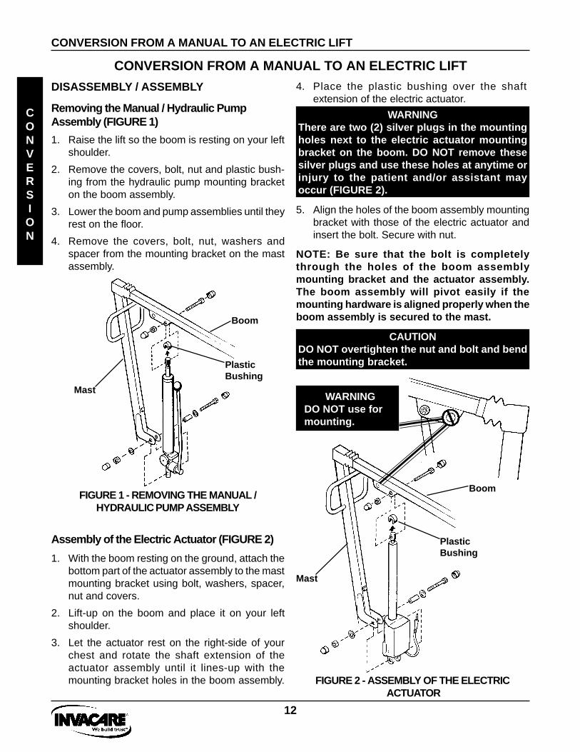
4. Place the plastic bushing over the shaftextension of the electric actuator.
CONVERSION
Assembly of the Electric Actuator (FIGURE 2)
DISASSEMBLY / ASSEMBLY
Removing the Manual / Hydraulic PumpAssembly (FIGURE 1)
1. Raise the lift so the boom is resting on your leftshoulder.
2. Remove the covers, bolt, nut and plastic bush-ing from the hydraulic pump mounting bracketon the boom assembly.
3. Lower the boom and pump assemblies until theyrest on the floor.
4. Remove the covers, bolt, nut, washers andspacer from the mounting bracket on the mastassembly.
FIGURE 1 - REMOVING THE MANUAL /HYDRAULIC PUMP ASSEMBLY
1. With the boom resting on the ground, attach thebottom part of the actuator assembly to the mastmounting bracket using bolt, washers, spacer,nut and covers.
2. Lift-up on the boom and place it on your leftshoulder.
3. Let the actuator rest on the right-side of yourchest and rotate the shaft extension of theactuator assembly until it lines-up with themounting bracket holes in the boom assembly.
Boom
Mast
WARNINGThere are two (2) silver plugs in the mountingholes next to the electric actuator mountingbracket on the boom. DO NOT remove thesesilver plugs and use these holes at anytime orinjury to the patient and/or assistant mayoccur (FIGURE 2).
WARNINGDO NOT use formounting.
Boom
Mast
PlasticBushing
CAUTIONDO NOT overtighten the nut and bolt and bendthe mounting bracket.
5. Align the holes of the boom assembly mountingbracket with those of the electric actuator andinsert the bolt. Secure with nut.
NOTE: Be sure that the bolt is completelythrough the holes of the boom assemblymounting bracket and the actuator assembly.The boom assembly will pivot easily if themounting hardware is aligned properly when theboom assembly is secured to the mast.
FIGURE 2 - ASSEMBLY OF THE ELECTRIC ACTUATOR
PlasticBushing

13
Attaching the Control Box to the Mast(FIGURE 3)
NOTE: When positioning the control box on the mast,make sure there is enough clearance between theEmergency Stop Button and the bottom of thesteering handle to be able toengage and disengagethe Emergency Stop Button.
CONVERSION FROM A MANUAL TO AN ELECTRIC LIFT
CONVERSION FROM A MANUAL TO AN ELECTRIC LIFT
FIGURE 3 - ATTACHING THE CONTROL BOXTO THE MAST
EmergencyStop Button
SteeringHandle
CONVERSION
CAUTIONIt is important to ensure that both input andoutput plugs are correctly inserted beforeconnection of power. If the patient lift ischarged with any other type of charger, it ispossible to irreparably damage the batteries.
FIGURE 4 - DISENGAGING THE EMERGENCYSTOP BUTTON
Disengage(RotateClockwise)
Engage(Push Down)
EmergencyStop Button
The charger automatically stops charging when thebatteries are fully charged; therefore, it is perfectlysafe to leave the patient lift on charge whenever itis not being used to ensure peak performance.
Battery Charging
WARNINGNEVER use or move the patient lift whilebattery is being charged.
NOTE: Ensure batteries are regularly charged,preferably EVERY NIGHT. This will prolong theirlife and maintain peak performance.
The battery charger is fully automatic and can beconnected to the lift at any time, OTHER THAN WHENLIFT IS IN USE. It is recommended that the lift chargingtake place in a well ventilated dry room. This should beEVERY NIGHT and/or when the audible alarm soundsduring operation. The battery charger has a round outputplug which is plugged into the patient lift hand-control.
The RED emergency stop button, mounted on the top ofcontrol box MUST be DISENGAGED (rotatedCLOCKWISE until fully out) during charging (FIGURE4).
From Electric Actuator
From HandControl
1. Standing behind the lift, hold the control boxagainst the right-side of the mast.
2. Place the U-bolts around the left-side of the mastand through the control box mounting holes.
3. Secure with washers and nuts.
4. Plug the cables from the actuator assembly andhand control into the control box.

14
NOTES
NOTES
NOTES
15
ONE- PIECE CONTOUR SLINGS
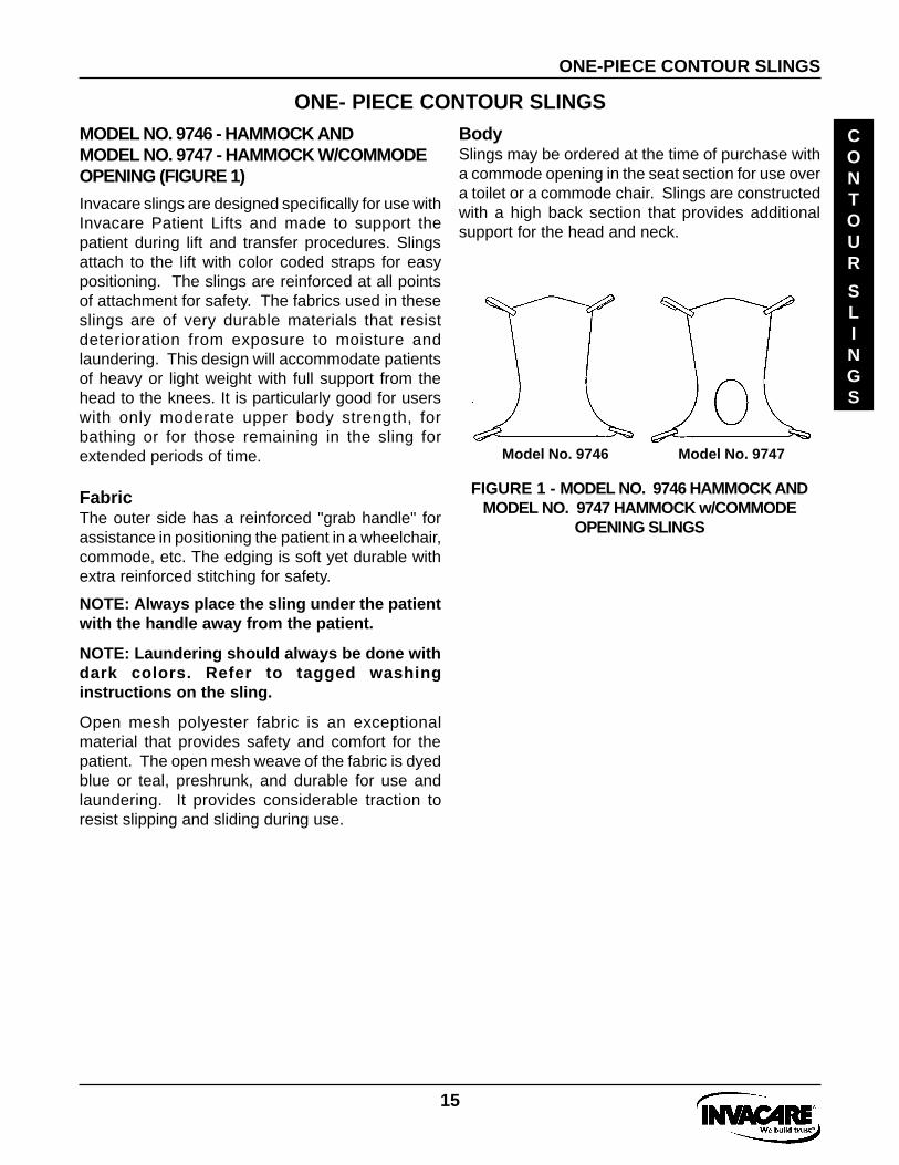
MODEL NO. 9746 - HAMMOCK ANDMODEL NO. 9747 - HAMMOCK W/COMMODEOPENING (FIGURE 1)
Invacare slings are designed specifically for use withInvacare Patient Lifts and made to support thepatient during lift and transfer procedures. Slingsattach to the lift with color coded straps for easypositioning. The slings are reinforced at all pointsof attachment for safety. The fabrics used in theseslings are of very durable materials that resistdeterioration from exposure to moisture andlaundering. This design will accommodate patientsof heavy or light weight with full support from thehead to the knees. It is particularly good for userswith only moderate upper body strength, forbathing or for those remaining in the sling forextended periods of time.
FabricThe outer side has a reinforced "grab handle" forassistance in positioning the patient in a wheelchair,commode, etc. The edging is soft yet durable withextra reinforced stitching for safety.
ONE-PIECE CONTOUR SLINGS
CONTOUR
SLINGS
Model No. 9746 Model No. 9747
BodySlings may be ordered at the time of purchase witha commode opening in the seat section for use overa toilet or a commode chair. Slings are constructedwith a high back section that provides additionalsupport for the head and neck.
FIGURE 1 - MODEL NO. 9746 HAMMOCK ANDMODEL NO. 9747 HAMMOCK w/COMMODE
OPENING SLINGS
NOTE: Always place the sling under the patientwith the handle away from the patient.
NOTE: Laundering should always be done withdark colors. Refer to tagged washinginstructions on the sling.
Open mesh polyester fabric is an exceptionalmaterial that provides safety and comfort for thepatient. The open mesh weave of the fabric is dyedblue or teal, preshrunk, and durable for use andlaundering. It provides considerable traction toresist slipping and sliding during use.
16
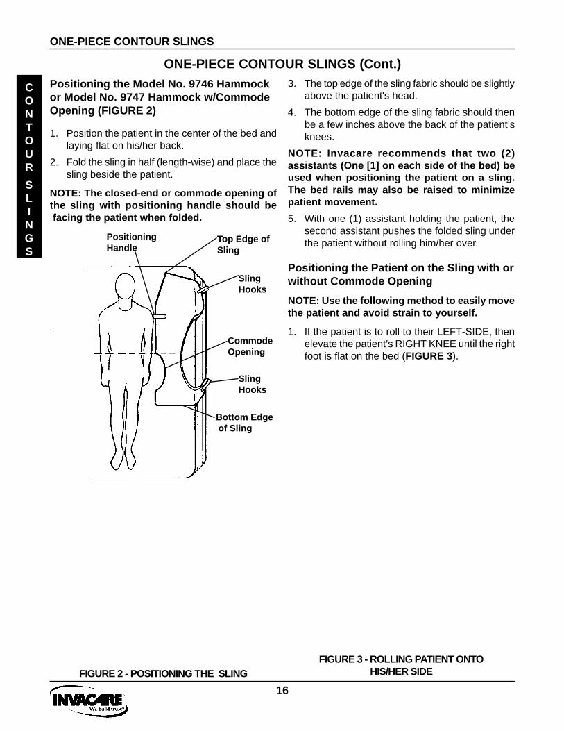
ONE-PIECE CONTOUR SLINGS (Cont.)3. The top edge of the sling fabric should be slightly
above the patient's head.
4. The bottom edge of the sling fabric should thenbe a few inches above the back of the patient’sknees.
NOTE: Invacare recommends that two (2)assistants (One [1] on each side of the bed) beused when positioning the patient on a sling.The bed rails may also be raised to minimizepatient movement.
5. With one (1) assistant holding the patient, thesecond assistant pushes the folded sling underthe patient without rolling him/her over.
Positioning the Patient on the Sling with orwithout Commode Opening
NOTE: Use the following method to easily movethe patient and avoid strain to yourself.
1. If the patient is to roll to their LEFT-SIDE, thenelevate the patient’s RIGHT KNEE until the rightfoot is flat on the bed (FIGURE 3).
FIGURE 3 - ROLLING PATIENT ONTOHIS/HER SIDE
Positioning the Model No. 9746 Hammockor Model No. 9747 Hammock w/CommodeOpening (FIGURE 2)
ONE-PIECE CONTOUR SLINGS
CONTOUR
SLINGS
FIGURE 2 - POSITIONING THE SLING
1. Position the patient in the center of the bed andlaying flat on his/her back.
2. Fold the sling in half (length-wise) and place thesling beside the patient.
NOTE: The closed-end or commode opening ofthe sling with positioning handle should be facing the patient when folded.
Top Edge ofSling
CommodeOpening
PositioningHandle
Bottom Edge of Sling
SlingHooks
SlingHooks

17
FIGURE 4 - ROLLING PATIENT ONTO HIS/HEROPPOSITE SIDE AND BACK
ONE-PIECE CONTOUR SLINGS (Cont.)NOTE: Invacare recommends that two (2)assistants (One [1] on each side of the bed) beused when positioning the patient onto a sling.
2. With an assistant on each side of the bed and upagainst the mattress, the assistant on the left-handside of the bed will position his/her RIGHT-HANDon the elevated KNEE and his/her LEFT-HANDunder the patient’s RIGHT SHOULDER, slowlypush on the knee and assist with a slight lift of theshoulder. The patient will easily roll onto their side(FIGURE 3).
3. With the patient on their side, push the fabricsof the seat and back gently under them(FIGURE 3).
NOTE: The patient’s head should be positionedin the headrest just below the top edge formaximum comfort and the lower edge of the seatsection positioned a few inches above the backof the patient’s knees (FIGURE 2).
4. Roll the patient on to his/her back (FIGURE 4).
NOTE: Assistants will reverse roles.
5. After the patient has been positioned once againon his/her back, you now need to roll the patientto their RIGHT-SIDE (facing the assistant on theLEFT).
6. With an assistant on each side of the bed andup against the mattress, the assistant on theright-hand side of the bed will elevate the LEFTKNEE and position his/her LEFT-HAND on theelevated KNEE and his/her RIGHT-HANDunder the patient’s LEFT SHOULDER, slowlypush on the knee and assist with a slight lift ofthe shoulder and the patient will easily roll ontotheir side (FIGURE 4).
7. Pull the fabrics of the seat and back across themattress until they are smooth (FIGURE 4).
8. Roll the patient onto their back and they shouldbe approximately centered on the sling section(FIGURE 4).
9. Attach the sling to the hooks of the swivel bar.Refer to Attaching the Slings to the PatientLift in LIFTING THE PATIENT Section of thismanual.
ONE-PIECE CONTOUR SLINGS
CONTOUR
SLINGS

18
UNIVERSAL DELUXE SLING
MODEL NO. 9742 -UNIVERSAL DELUXESLING (FIGURES 1A and 1B)
FIGURE 1A - POSITIONING THE PATIENT INTHE MODEL NO. 9742 - UNIVERSAL DELUXE
SLING
UNIVERSAL DELUXE SLING
UNIVERSAL
DELUXE
SLING
Positioning the Patient in theModel No. 9742 Universal Deluxe Sling
NOTE: Headrest is not available on the ModelNo. 9742 Universal Deluxe Sling.
NOTE: Invacare recommends that two (2)assistants (one [1] in front and one [1] in backof the wheelchair) be used when positioning thepatient in the universal deluxe sling.
NOTE: Use the following method to easily movethe patient and avoid strain to yourself.
WARNINGIf the patient is in a wheelchair, secure the wheellocks in place to prevent the chair from movingforward or backwards.
1. The rear wheel locks of the wheelchair are lockedto prevent movement of the chair.
2. With the patient sitting in a chair one (1)assistant in the front and the other assistant inthe back, lean the patient forward.
NOTE: The front assistant will be supporting theweight of the patient.
3. Place the universal deluxe sling behind thepatient (with "grab handle" on the outside) andbring the flaps out alongside the patient’s legs.
NOTE: The back of the universal deluxe slingshould be parallel to the patient’s upper armsand be positioned between the top of thepatient’s back and the top of the chair back.
4. With the back of the sling positioned properly,push the edges of the commode opening underthe patient’s buttocks.
5. Lean the patient back into the chair with theassistant in the rear supporting his/her weight.
6. Lift the patient’s legs (one at a time) and reachunder the patient’s leg and pull until the front ofthe sling is behind the patient’s knees (aboutthree [3] inches) and the back of the slingremains in position.
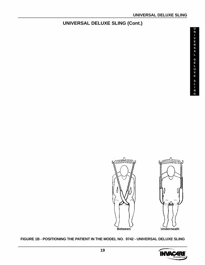
NOTE: The straps may be crossed BETWEENor UNDERNEATH the patient's legs.
7. Attach the sling to the swivel bar. Refer toAttaching the Slings to the Patient Lift inLIFTING THE PATIENT Section of this manual.
19
UNIVERSAL DELUXE SLING (Cont.)
FIGURE 1B - POSITIONING THE PATIENT IN THE MODEL NO. 9742 - UNIVERSAL DELUXE SLING
UNIVERSAL
DELUXE
SLING
UNIVERSAL DELUXE SLING
Between Underneath

20
OPERATION
OPERATING THE PATIENT LIFT (FIGURE 1)
OPERATION
OPERATION
To Close/Open the Legs of the Base Assembly
The shifter handle is used to open or close the legs of thebase for stability when lifting a patient.
WARNINGThe operation of the patient lift is an easy and safeprocedure. DO NOT attempt any transfer withoutapproval of the patient’s physician, nurse ormedical assistant. Thoroughly read the instructionsin this Owner’s Manual, observe a trained team ofexperts performing the lifting procedures and thenperform the entire lift procedure several times withproper supervision and a capable individual actingas a patient.
ONLY operate this lift with the legs in MAXIMUMOPEN POSITION and LOCKED in place. The baselegs MUST be locked in the open position at all timesfor stability and patient safety when lifting andtransferring a patient.
1. Stand at the rear of the patient lift and grasp the shifterhandle with one (1) hand and place the opposite handon the steering handle of the mast for balance.
There are two (2) controls on the pumpassembly:
a. The control valve
b. The pump handle
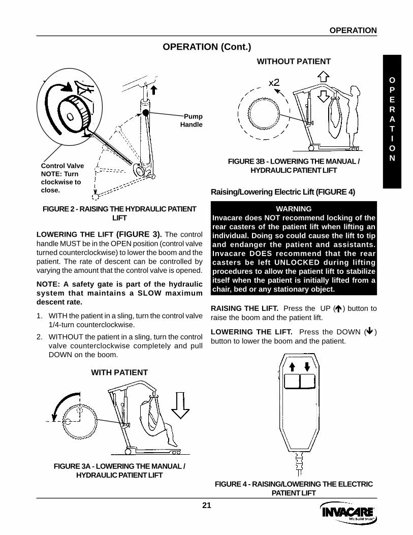
RAISING THE LIFT (FIGURE 2). The control valveMUST be in the closed position (turn control valveclockwise until tight) to move the pump handle upand down and elevate the boom and the patient.
Raising/Lowering Manual/Hydraulic Lift
WARNINGInvacare does NOT recommend locking of therear casters of the patient lift when lifting anindividual. Doing so could cause the lift to tipand endanger the patient and assistants.Invacare DOES recommend that the rearcasters be left UNLOCKED during liftingprocedures to allow the patient lift to stabilizeitself when the patient is initially lifted from achair, bed or any stationary object.
FIGURE 1- TO CLOSE/OPEN THE LEGS OF THEBASE ASSEMBLY
NOTE: The shifter handle MUST lock into itsmounting slot to lock the legs in the full openor closes position.
WARNINGIf the shifter handle is NOT positionedcompletely into its mounting slot, DO NOT usethe patient lift until shifter handle is properlyseated and the legs of the patient lift LOCKEDin place or injury and/or damage may occur.
TO CLOSE.2. Push the shifter handle OUT and away from the
patient lift and then to your LEFT until it LOCKS in thenotch of the bracket.
TO OPEN.3. Push the shifter handle OUT and away from the
patient lift and then to your RIGHT until it LOCKS inthe notch of the bracket.
TO OPEN
TO CLOSE
21
OPERATION (Cont.)
OPERATION
OPERATION
FIGURE 4 - RAISING/LOWERING THE ELECTRICPATIENT LIFT
WARNINGInvacare does NOT recommend locking of therear casters of the patient lift when lifting anindividual. Doing so could cause the lift to tipand endanger the patient and assistants.Invacare DOES recommend that the rearcasters be left UNLOCKED during liftingprocedures to allow the patient lift to stabilizeitself when the patient is initially lifted from achair, bed or any stationary object.
RAISING THE LIFT. Press the UP (é) button toraise the boom and the patient lift.
LOWERING THE LIFT. Press the DOWN (ê)button to lower the boom and the patient.
Raising/Lowering Electric Lift (FIGURE 4)
WITHOUT PATIENT
FIGURE 3B - LOWERING THE MANUAL /HYDRAULIC PATIENT LIFT
FIGURE 2 - RAISING THE HYDRAULIC PATIENTLIFT
PumpHandle
Control ValveNOTE: Turnclockwise toclose.
LOWERING THE LIFT (FIGURE 3). The controlhandle MUST be in the OPEN position (control valveturned counterclockwise) to lower the boom and thepatient. The rate of descent can be controlled byvarying the amount that the control valve is opened.
NOTE: A safety gate is part of the hydraulicsystem that maintains a SLOW maximumdescent rate.
1. WITH the patient in a sling, turn the control valve1/4-turn counterclockwise.
2. WITHOUT the patient in a sling, turn the controlvalve counterclockwise completely and pullDOWN on the boom.
WITH PATIENT
FIGURE 3A - LOWERING THE MANUAL /HYDRAULIC PATIENT LIFT

22
LIFTING THE PATIENT
NOTE: Refer to PATIENT LIFT SAFETY SUMMARY inthe front of this manual before proceeding furtherand observe all WARNINGS indicated.
WARNINGBefore lifting or transferring the patient, thebase legs MUST be LOCKED in the OPENposition for optimum stability and safety.
NOTE: Before positioning the legs of the patientlift under the bed, make sure that the area is clearof any obstructions.
1. With the legs of the base OPEN and LOCKED,use the steering handle to push the patient liftunderneath the bed.
2. Lower the patient lift for easy attachment of thesling.
ATTACHING THE SLINGS TO THE PATIENTLIFT (FIGURE 1)
CAUTIONWhen connecting the sling to the patient lift,the shortest of the straps MUST be at the backof the patient for support. Using the longsection will leave little or no support for thepatient's back. The loops of the sling are colorcoded and can be used to place the patient invarious positions. The colors make it easy toconnect both sides of the sling equally. Makesure that there is sufficient head support whenlifting a patient.
3. Place the straps of the sling over the hooks ofthe swivel bar. Match the corresponding colorson each side of the sling for an even lift of thepatient (FIGURE 1).
NOTE: Model No. 9746 - Hammock and Model No.9747 - Hammock w/Commode have four (4) slingstraps while Model No. 9742 - Universal Deluxe Slinghas six (6) sling straps.
LIFTING THE PATIENT
LIFTING
PATIENT
FIGURE 1 - ATTACHING THE SLINGS TO THE PATIENT LIFT
HAMMOCK SLING WITH OR WITHOUT COMMODEOPENING (FOUR [4] STRAPS ONLY)
Color CodedStraps
Color CodedStraps
UNIVERSAL DELUXE SLING W/OUT HEADRESTWITH COMMODE OPENING (SIX [6] STRAPS)

23
LIFTING THE PATIENT (Cont.)
LIFTING / MOVING THE PATIENT
FIGURE 3 - MOVING THE PATIENT
WARNINGWhen elevated a few inches off the surface ofthe bed and before moving the patient, checkagain to make sure that the sling is properlyconnected to the hooks of the swivel bar. If anyattachments are NOT properly in place, lowerthe patient back onto the bed and correct thisproblem.
Adjustments for safety and comfort should bemade before moving the patient. Patient’s armsshould be inside of the straps.
Invacare slings are made specifically for usewith Invacare Patient Lifts. For the safety of thepatient, DO NOT intermix slings and patient liftsof different manufacturers. Warranty will bevoided.
3. When patient is clear of the bed surface, swingtheir feet off the bed (FIGURE 3).
4. Using the steering handles, move the lift awayfrom the bed.
FIGURE 2 - LIFTING THE PATIENT
LIFTING THE PATIENT
LIFTING
PATIENT
NOTE: DO NOT engage the rear locking casterswhen patient is in the lift.
1. Pump the lift handle or press the UP (é) buttonto raise the patient above the bed. The patientshould be elevated high enough to clear the bedwith their weight fully supported by the lift.
NOTE: On manual / hydraulic lift, the boom willstay in position until the control valve is opened.On the electric lift, the boom will stay inposition until the DOWN ( ê) button is pressed.
2. When the patient is lifted from the bed (with thepatient’s head supported by the sling and/or anassistant), he/she will be raised to a sittingposition (FIGURE 2).
24
LIFTING THE PATIENT (Cont.)
LIFTING THE PATIENT
LIFTING
PATIENT
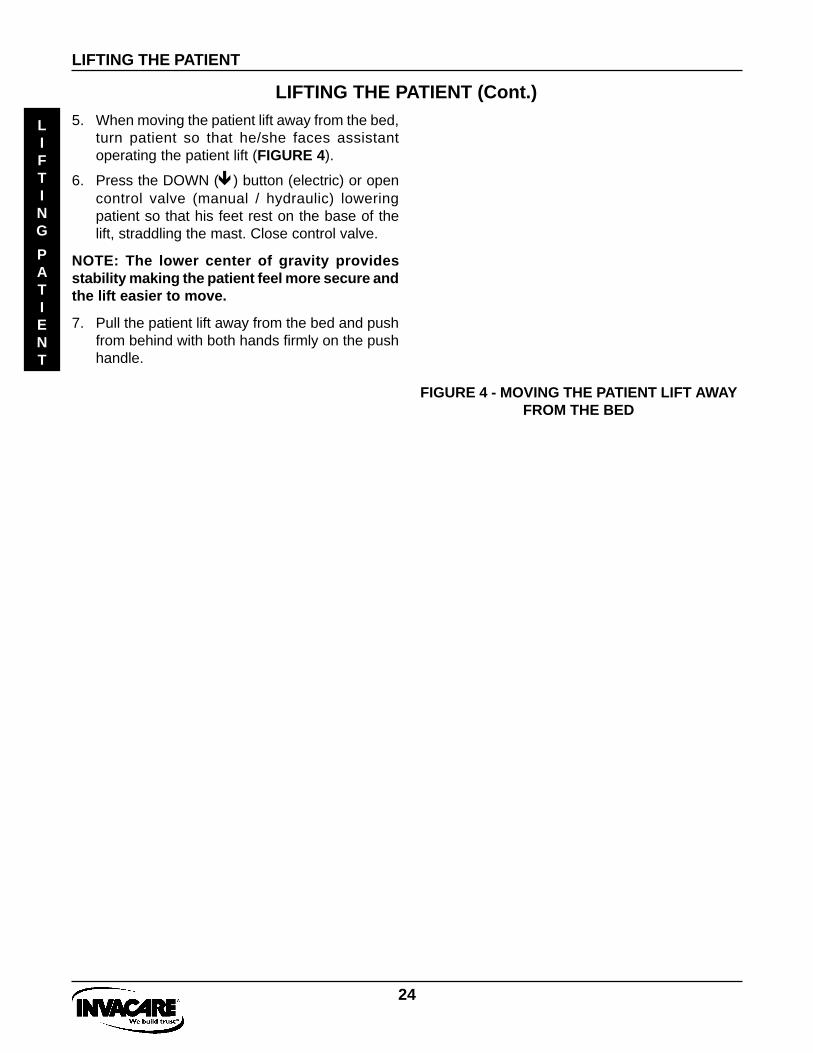
5. When moving the patient lift away from the bed,turn patient so that he/she faces assistantoperating the patient lift (FIGURE 4).
6. Press the DOWN (ê) button (electric) or opencontrol valve (manual / hydraulic) loweringpatient so that his feet rest on the base of thelift, straddling the mast. Close control valve.
NOTE: The lower center of gravity providesstability making the patient feel more secure andthe lift easier to move.
7. Pull the patient lift away from the bed and pushfrom behind with both hands firmly on the pushhandle.
FIGURE 4 - MOVING THE PATIENT LIFT AWAYFROM THE BED

25
3. With the help of both assistants, guide thepatient onto the commode chair.
4. Lower the patient onto the commode chairleaving the sling attached to the swivel barhooks.
5. When complete, recheck for correct attachmentand then raise the patient off of the commodechair.
6. When patient is clear of the commode surface(using the steering handles), move the lift awayfrom the commode chair.
7. To return patient to bed, reverse proceduresconcerning lifting the patient, operation and slingattachment.
8. To return or place patient in a wheelchair, referto TRANSFERRING TO A WHEELCHAIR .
TRANSFERRING PATIENT FOR USE OF THE BATHROOM FACILITIES
TRANSFERRING PATIENT FOR USE OF THE BATHROOM FACILITIES
TRANSFERRING PATIENT FOR USE OF ACOMMODE CHAIR OR STANDARDCOMMODE B
ATHROOM
The slings with commode openings are designed tobe used with either a commode chair or standardcommode.
NOTE: Invacare recommends that the slingremain connected to the swivel bar hooksduring the patient’s use of either the commodechair or standard commode.
WARNINGWhen elevated a few inches off the surface ofthe commode chair or standard commode andbefore moving the patient, check again to makesure that the sling is properly connected to theswivel bar hooks. If the sling attachments areNOT properly in place, lower the patient backonto the commode chair or standard commodeto correct this problem.
Adjustments for safety and comfort should bemade before moving the patient. Patient’s armsshould be inside of the straps.
Invacare slings are made specifically for usewith Invacare Patient Lifts. For the safety of thepatient, DO NOT intermix slings and patient liftsof different manufacturers. Warranty will bevoided.
Invacare does NOT recommend locking of therear casters of the patient lift when lifting anindividual. Doing so could cause the lift to tipand endanger the patient and assistants.Invacare DOES recommend that the rearcasters be left UNLOCKED during lifting pro-cedures to allow the patient lift to stabilize it-self when the patient is initially lifted from achair, bed or any stationary object.
1. To lift the patient from the bed, follow theprocedures concerning lifting the patient,operation and sling attachment.
2. The patient should be elevated high enough toclear the commode chair arms and their weightsupported by the patient lift.
Transferring to a Commode Chair(FIGURE 1)
FIGURE 1 - TRANSFERRING TO A COMMODECHAIR

26
TRANSFERRING PATIENT FOR USE OF THE BATHROOM FACILITIES
TRANSFERRING PATIENT FOR USE OF THE BATHROOM FACILITIES
Transferring to a Standard Commode
NOTE: The patient MUST be transferred to aWHEELCHAIR and transported to the bathroomfacilities before using the patient lift again toposition the patient on a standard commode.Refer to TRANSFERRING TO A WHEELCHAIR inthis manual . After this has been accomplishedrefer to the following:
1. To lift the patient from the bed, follow theprocedures concerning lifting the patient,operation and sling attachment.
2. The patient should be elevated high enough toclear the standard commode and their weightsupported by the patient lift.
3. With the help of both assistants, guide thepatient onto the standard commode.
4. Lower the patient onto the standard commodeleaving the sling attached to the swivel barhooks.
5. When complete, recheck for correct attachmentand then raise the patient off of the standardcommode.
6. When patient is clear of the standard commodesurface (using the steering handles), move thelift away from the standard commode.
7. To return or place patient in a wheelchair, referto TRANSFERRING TO A WHEELCHAIR .
8. To return patient to bed, reverse proceduresconcerning lifting the patient, operation and slingattachment.
TRANSFERRING TO A BATHING UNIT
WARNINGWhen elevated a few inches off the surface of thebed and before moving the patient, check again tomake sure that the sling is properly connected tothe swivel bar hooks. If any attachments are NOTproperly in place, lower the patient completely tocorrect this problem.
Adjustments for safety and comfort should be madebefore moving the patient. Patient's arms should beinside of the straps.
Invacare slings are made specifically for use withInvacare Patient Lifts. For the safety of the patient,DO NOT intermix slings and patient lifts of differentmanufacturers. Warranty will be voided.
Invacare does NOT recommend locking of the rearcasters of the patient lift when lifting an individual.Doing so could cause the lift to tip and endangerthe patient and assistants. Invacare DOESrecommend that the rear casters be left UNLOCKEDduring lifting procedures to allow the patient lift tostabilize itself when the patient is initially lifted froma chair, bed or any stationary object.
BATHROOM
NOTE: There are many portable bathingapparatuses; this is an example of one. Refer toyour particular portable bath instructions anduse them in conjunction with this Owner’sManual.
1. To remove the patient from the bed, observeprocedures concerning sling attachment,operation and lifting the patient.
2. The patient should be elevated high enough toclear the bed and be able to slide the portablebath tub under the patient.
3. Lower the patient into the portable bath tub.
4. Detach the sling from the swivel bar hooks andattach the portable bath tub straps to the patientlift.
5. Using the lift, raise the sides of the portable bathtub.
6. Bathe patient.
7. Reverse procedures to return patient to bed.

27
TRANSFERRING TO A WHEELCHAIR
TRANSFERRING TO A WHEELCHAIR(FIGURE 1)
TRANSFERRING TO A WHEELCHAIR
TRANSFER
WHEELCHAIR
FIGURE 1 - TRANSFERRING TO A WHEELCHAIR
6. With one (1) assistant behind the chair and theother operating the patient lift, the assistantbehind the chair will pull back on the "grab handle"or sides of the sling to seat the patient well into theback of the chair. This will maintain a good centerof balance and prevent the chair from tippingforward.
7. The sling is left in place.
8. To return to the seating surface, reverseprocedures concerning lifting the patient, opera-tion and sling attachments.
WARNINGBe sure to check the sling attachments eachtime the sling is removed and replaced, toensure that it is properly attached before thepatient is removed from the bed or chair.
WARNINGWhen elevated a few inches off a seating surfaceand before moving the patient, check again to makesure that the sling is properly connected. If anyattachments are NOT properly in place, lower thepatient completely to correct this problem.
Adjustments for safety and comfort should be madebefore moving the patient. Patient’s arms should beinside of the straps.
Invacare slings are made specifically for use withInvacare Patient Lifts. For the safety of thepatient, DO NOT intermix slings and patient lifts ofdifferent manufacturers. Warranty will be voided.
Invacare does NOT recommend locking of the rearcasters of the patient lift when lifting an individual.Doing so could cause the lift to tip and endangerthe patient and assistants. Invacare DOESrecommend that the rear casters be left UNLOCKEDduring lifting procedures to allow the patient lift tostabilize itself when the patient is initially lifted froma chair, bed or any stationary object.
NOTE: Invacare recommends that two (2) assistantsbe used when transferring a patient to a wheelchair.
NOTE: To position an individual in a sling, follow theprocedures concerning lifting the patient, operationand sling attachments.
1. The legs of the lift (w/patient) are in the openedposition.
2. The wheelchair is moved into position.
WARNINGWheelchair wheel locks MUST be in a locked posi-tion before lowering the patient into the wheelchairfor transport.
3. The rear wheel locks of the wheelchair are lockedto prevent movement of the chair.
4. The patient is positioned over the seat with theirback against the back of the chair.
5. Begin to lower the patient either by opening thecontrol valve or by pressing the DOWN (ê )button.

28
TRANSFERRING FROM A WHEELCHAIR TO A CAR
TRANSFERRING FROM A WHEELCHAIRTO A CAR (FIGURES 1A AND 1B)
FIGURE 1A - TRANSFERRING FROM AWHEELCHAIR TO A CAR
TRANSFERRING FROM A WHEELCHAIR TO A CAR
TRANSFER
CAR
NOTE: Invacare recommends that two (2) assistantsbe used when transferring a patient from a wheelchairto a car.
WARNINGWhen elevated a few inches off the seatingsurface of the wheelchair and before moving thepatient, check again to make sure that the slingis properly connected to swivel bar hooks. If anyattachments are NOT properly in place, lower thepatient completely to correct this problem.
Adjustments for safety and comfort should bemade before moving the patient. Patient’s armsshould be inside of the straps.
Invacare slings are made specifically for use withInvacare Patient Lifts. For the safety of thepatient, DO NOT intermix slings and patient liftsof different manufacturers. Warranty will bevoided.
Invacare does NOT recommend locking of therear casters of the patient lift when lifting anindividual. Doing so could cause the lift to tip andendanger the patient and assistants. InvacareDOES recommend that the rear casters be leftUNLOCKED during lifting procedures to allow thepatient lift to stabilize itself when the patient isinitially lifted from a chair, bed or any stationaryobject.
1. The rear wheel locks of the wheelchair are lockedto prevent movement of the chair.
2. Attach the sling to the swivel bar hooks.
3. Lift the patient from the wheelchair.
Transfer to a car is easily accomplished with theuse of Invacare’s patient lifts and slings. Thetransfer to a car should be made on a leveldriveway or surface.
NOTE: Before lifting the patient from the chair,make sure to shorten the distance between thepatient and the boom. This will make thetransfer into the seat of the car easier.
NOTE: Attendants should practice "Good BodyMechanics" when positioning patient onto anyseating surface.

29
TRANSFERRING FROM A WHEELCHAIR TO A CAR
TRANSFERRING FROM A WHEELCHAIR TO A CAR
TRANSFER
CAR
8. While one (1) assistant is holding the patient,the other assistant removes the straps from theswivel bar and slides the patient lift out of theway.
9. The sling may be left under the patient orremoved.
10. The mast, boom and pump assembly may beremoved from the base and transported in thecar.
NOTE: If the patient lift and wheelchair are bothpacked in the trunk of the car, care should betaken not to damage the spokes of thewheelchair on the patient lift.
4. The lift is moved, by the steering handles, to aposition close to the doorway of the car.
5. Lower the boom of the lift until the hooks of the swivelbar are even with the roof of the car.
6. As one (1) assistant pushes the patient into the carby his knees until he/she is positioned over the seatof the car, the other assistant lowers the boom. Asthe boom is being lowered, the first assistant is notonly pushing but turning the patient so he/she ispositioned facing the front of the car.
7. The patient will come to rest on the seat of the car.
FIGURE 1B - TRANSFERRING FROM A WHEELCHAIR TO A CAR

30
TRANSFERRING FROM A CAR TO A WHEELCHAIR
TRANSFERRING FROM A CAR TO AWHEELCHAIR (FIGURE 1)
FIGURE 1 - TRANSFERRING FROM A CAR TOA WHEELCHAIR
6. The second assistant should pull the patient liftaway from the car until the patient is completelyclear of the door frame.
7. Release the patient back to his/her normal sit-ting position in the sling.
8. Position the wheelchair under the patient.
9. Engage the rear wheel locks of the wheelchair.
WARNINGWheelchair wheel locks MUST be in a lockedposition before lowering the patient into thewheelchair for transport.
10. One (1) assistant will slowly lower the patientinto the wheelchair while the other assistantguides him/her into the chair.
TRANSFERRING FROM A CAR TO A WHEELCHAIR
NOTE: Invacare recommends that two (2)assistants be used when transferring a patientfrom a wheelchair to a car.
WARNINGWhen elevated a few inches off the seat of thecar and before moving the patient, check againto make sure that the sling is properlyconnected to the swivel bar hooks. If anyattachments are NOT properly in place, lowerthe patient completely to correct this problem.
Adjustments for safety and comfort should bemade before moving the patient. Patient’s armsshould be inside of the straps.
Invacare slings are made specifically for usewith Invacare Patient Lifts. For the safety of thepatient, DO NOT intermix slings and patient liftsof different manufacturers. Warranty will bevoided.
Invacare does NOT recommend locking of therear casters of the patient lift when lifting anindividual. Doing so could cause the lift to tipand endanger the patient and assistants.Invacare DOES recommend that the rearcasters be left UNLOCKED during liftingprocedures to allow the patient lift to stabilizeitself when the patient is initially lifted from achair, bed or any stationary object.
CAR
TO
WHEELCHAIR
NOTE: One (1) assistant will support patient atall times.
1. With the first assistant supporting the patient,the second assistant then lowers the boom ofthe patient lift until the hooks of the swivel bar areeven with the roof of the car.
2. Attach the sling to the swivel bar.
3. Lift patient up off of seat until straps are taut.
4. Turn patient with sling until legs are outside ofcar.
NOTE: Attendants should practice "Good BodyMechanics" when positioning patient onto anyseating surface.
5. Lift up on legs with one (1) hand and tilt thepatient’s back with the other hand.

31
TROUBLESHOOTING
SYMPTOMS FAULTS SOLUTION
Foot pedal pressure loose.
Fluff or debris in bearings.
Needs lubrication.
Hydraulic pump in need of service.
Handwheel not fully closed.
Manual / Hydraulic pump in needof service.
Hand-control or actuator connectorloose.
Batteries low.
Push RED Emergency StopButton down.
Electric actuator in need ofservice.
Refer to Foot Pedal Adjustment inthe CARE AND MAINTENANCEsection in this manual.
Refer to Casters in the CARE ANDMAINTENANCE section in thismanual.
Refer to Lubrication in the CAREAND MAINTENANCE section inthis manual.
Refer to Manual / Hydraulic orElectric Actuator Replacement inthe CARE AND MAINTENANCEsection of this manual. Contact yourDealer.
Close handwheel.
Refer to Manual / Hydraulic orElectric Actuator Replacement inthe CARE AND MAINTENANCEsection of this manual. Contact yourDealer.
Check connections.
Charge batteries. Refer to BatteryCharging in the CONVERSIONFROM A MANUAL TO AN ELEC-TRIC LIFT section of this manual.
Rotate clockwise to operate.
Refer to Manual / Hydraulic orElectric Actuator Replacement inthe CARE AND MAINTENANCEsection of this manual. Contact yourDealer.
Patient Lift feels loose.
Casters/Brakes noisy or stiff.
Noisy or dry sound from pivots.
Oil leaking from hydraulics.
Manual / Hydraulic pump fails tolift when pumped.
Electric actuator fails to lift whenbutton is pressed.
TROUBLESHOOTING
TROUBLESHOOTING
NOTE: If problems are not remedied by the suggested means, please contact your Dealer orInvacare.

32
MAINTENANCE SAFETY INSPECTION CHECKLIST
INITIALLYITEM INSPECT/ADJUSTMONTHLY
INSPECT/ADJUSTPERIODICALLY
X
XX
X
XX
XXX
X
XX
XXX
XXX
X
X
X
X
X
X
XXXX
XX
XX
XXX
X
XX
XX
X
X
X
X
XXX
THE CASTER BASEInspect for missing hardware.Base opens/closes with ease.Inspect casters and axle bolts for tightness.Inspect casters for smooth swivel and roll.Apply a light grease to caster ball bearings.
SHIFTER HANDLEOperates smoothly.Locks adjustable base whenever engaged.
THE MASTMast should lock securely when assembled.Inspect for bends or deflections.
THE BOOMCheck all hardware and swivel bar supports.Inspect for bends or deflections.Inspect bolted joints of boom for wear.Inspect to ensure that the boom is
centered between the base legs.
THE SWIVEL BARCheck the hooks for wear or damage.Check sling hooks for wear or deflection.
THE PUMP ASSEMBLYCheck for leakage.Inspect hardware on mast and boom.Check for wear or deflection of rod.(IF DAMAGED, RETURN TO FACTORY).
THE PUMP HANDLECheck for smooth operation.
THE CONTROL VALVEOpens and closes easily.
CLEANINGWhenever necessary.
SLINGS AND HARDWARECHECK ALL SLING ATTACHMENTS each
time it is used to ensure properconnection and patient safety.
Inspect sling material for wear.Inspect straps for wear.
INSPECTION
CHECKLIST
MAINTENANCE SAFETY INSPECTION CHECKLIST
33
CARE AND MAINTENANCE OF YOUR PATIENT LIFT
CARE AND MAINTENANCE OF YOUR PATIENT LIFTCARE-
MAINTENANCE
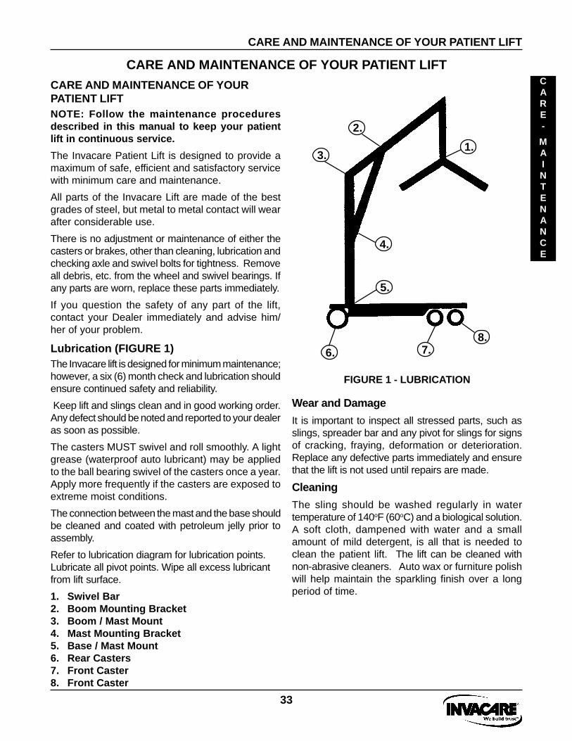
FIGURE 1 - LUBRICATION
1.
5.
2.
3.
4.
6.8.
7.
CARE AND MAINTENANCE OF YOURPATIENT LIFT
Wear and Damage
It is important to inspect all stressed parts, such asslings, spreader bar and any pivot for slings for signsof cracking, fraying, deformation or deterioration.Replace any defective parts immediately and ensurethat the lift is not used until repairs are made.
Cleaning
The sling should be washed regularly in watertemperature of 140oF (60oC) and a biological solution.A soft cloth, dampened with water and a smallamount of mild detergent, is all that is needed toclean the patient lift. The lift can be cleaned withnon-abrasive cleaners. Auto wax or furniture polishwill help maintain the sparkling finish over a longperiod of time.
NOTE: Follow the maintenance proceduresdescribed in this manual to keep your patientlift in continuous service.
The Invacare Patient Lift is designed to provide amaximum of safe, efficient and satisfactory servicewith minimum care and maintenance.
All parts of the Invacare Lift are made of the bestgrades of steel, but metal to metal contact will wearafter considerable use.
There is no adjustment or maintenance of either thecasters or brakes, other than cleaning, lubrication andchecking axle and swivel bolts for tightness. Removeall debris, etc. from the wheel and swivel bearings. Ifany parts are worn, replace these parts immediately.
If you question the safety of any part of the lift,contact your Dealer immediately and advise him/her of your problem.
Lubrication (FIGURE 1)The Invacare lift is designed for minimum maintenance;however, a six (6) month check and lubrication shouldensure continued safety and reliability.
Keep lift and slings clean and in good working order.Any defect should be noted and reported to your dealeras soon as possible.
The casters MUST swivel and roll smoothly. A lightgrease (waterproof auto lubricant) may be appliedto the ball bearing swivel of the casters once a year.Apply more frequently if the casters are exposed toextreme moist conditions.
The connection between the mast and the base shouldbe cleaned and coated with petroleum jelly prior toassembly.
Refer to lubrication diagram for lubrication points.Lubricate all pivot points. Wipe all excess lubricantfrom lift surface.
1. Swivel Bar2. Boom Mounting Bracket3. Boom / Mast Mount4. Mast Mounting Bracket5. Base / Mast Mount6. Rear Casters7. Front Caster8. Front Caster

34
CARE AND MAINTENANCE OF YOUR PATIENT LIFTCARE-
MAINTENANCE
CARE AND MAINTENANCE OF YOUR PATIENT LIFT
Manual / Hydraulic Pump
All parts of the Manual / Hydraulic Pump areprecision machined, then carefully assembled andtested to ensure reliable service. The pumpassembly is completely enclosed and sealed withNeoprene rings to prevent leakage of hydraulic oil.A small amount of oil (about a drop) will accumulatearound the piston from time to time and should beremoved with a facial tissue.
WARNINGThe pump is sealed at the factory and if serviceis required, the pump unit MUST be returned tothe factory for repair. DO NOT attempt to OPENthe pump or obtain local service as this will voidthe warranty and might result in damage andcostly repair. Consult your dealer or writeInvacare for information.
MANUAL / HYDRAULIC PUMP OR ELECTRICACTUATOR REPLACEMENT (FIGURE 2).
1. Remove the covers, nut, bolt and plastic bushing fromthe boom mounting bracket.
2. Remove the covers, nut, bolt, washers and spacerfrom the mast mounting bracket.
3. Reverse steps for installation.
CAUTIONDO NOT overtighten mounting hardware. This willdamage mounting brackets.
FIGURE 2 - MANUAL / HYDRAULIC PUMP ORELECTRIC ACTUATOR REPLACEMENT
Boom
Mast
PlasticBushing
WARNINGDO NOT use formounting.
Boom
Mast
PlasticBushing
WARNINGDO NOT use formounting.
ELECTRIC
MANUAL / HYDRAULIC
35
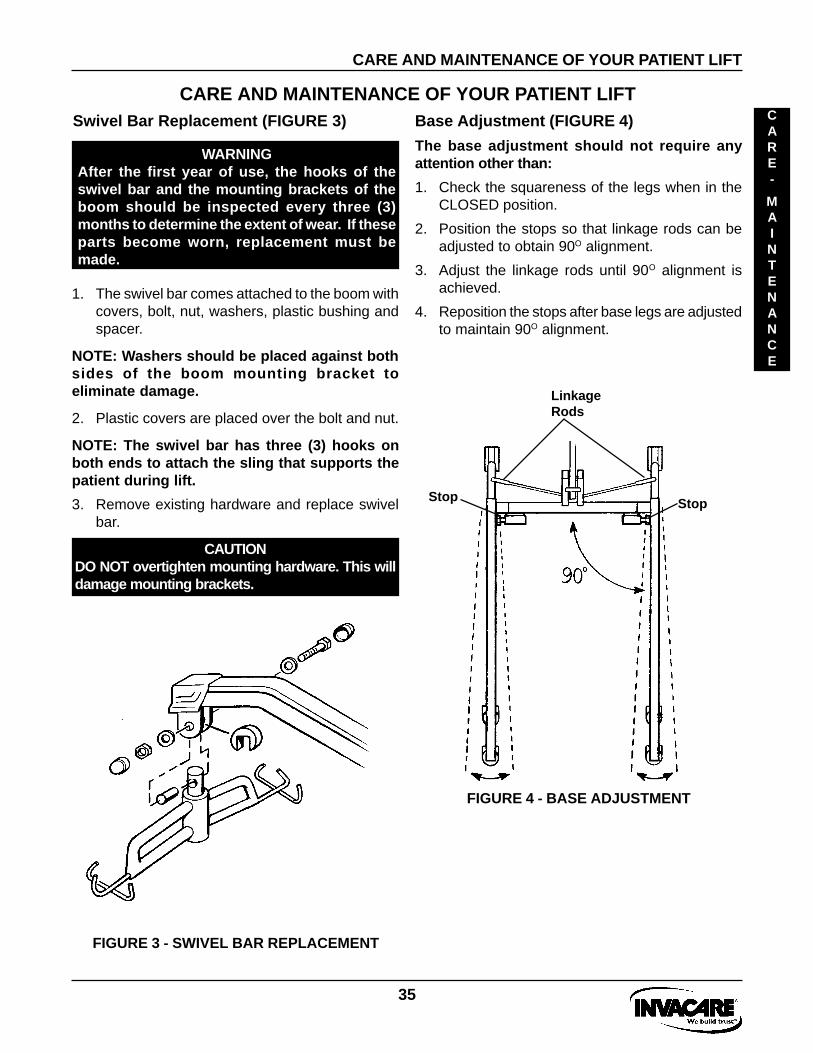
CARE AND MAINTENANCE OF YOUR PATIENT LIFTBase Adjustment (FIGURE 4)
The base adjustment should not require anyattention other than:
1. Check the squareness of the legs when in theCLOSED position.
2. Position the stops so that linkage rods can beadjusted to obtain 90O alignment.
3. Adjust the linkage rods until 90O alignment isachieved.
4. Reposition the stops after base legs are adjustedto maintain 90O alignment.
FIGURE 3 - SWIVEL BAR REPLACEMENT
Swivel Bar Replacement (FIGURE 3)
WARNINGAfter the first year of use, the hooks of theswivel bar and the mounting brackets of theboom should be inspected every three (3)months to determine the extent of wear. If theseparts become worn, replacement must bemade.
1. The swivel bar comes attached to the boom withcovers, bolt, nut, washers, plastic bushing andspacer.
NOTE: Washers should be placed against bothsides of the boom mounting bracket toeliminate damage.
2. Plastic covers are placed over the bolt and nut.
NOTE: The swivel bar has three (3) hooks onboth ends to attach the sling that supports thepatient during lift.
3. Remove existing hardware and replace swivelbar.
CAUTIONDO NOT overtighten mounting hardware. This willdamage mounting brackets.
CARE AND MAINTENANCE OF YOUR PATIENT LIFT
CARE-
-
MAINTENANCE
FIGURE 4 - BASE ADJUSTMENT
LinkageRods
StopStop

36
FRONT CASTER REPLACEMENT.
CARE AND MAINTENANCE OF YOUR PATIENT LIFT
Shifter Handle Adjustment (FIGURE 5)
NOTE: When removing the casters from itsmounting bracket, the caster will come apart asshown in FIGURE 6. Reassemble as shown.
1. To remove the casters ONLY, remove the nut andbolt that secure the casters to the base mountingbracket (FIGURE 7).
2. If cleaning the casters, remove caps, spacers andbearings. Reassemble as shown in FIGURE 7.
Cap
SpacerBearing
Caster
Nut
Bearing
Spacer
CapCap
SpacerCaster Bearing
FIGURE 7 - FRONT CASTER REPLACEMENT
1. Check the free movement of the linkage rodsand tighten or lubricate if necessary.
2. Check the shifter handle operation. Thelocknut should be tighten completely to preventthe legs from opening accidentally.
FIGURE 8 - FRONT CASTER HOUSING REMOVAL
FRONT CASTER HOUSING REMOVAL(FIGURE 8).
NOTE: It may be necessary to remove the casterbefore removing the caster housing. To perform thisprocedure without removing the caster, a cut-downAllen wrench will have to be used.
1. Using a cut-down Allen wrench, remove the buttonhead screw and nut that secures the caster housingto the base.
2. Replace with new housing and secure.
CARE-
MAINTENANCE
Bolt
CARE AND MAINTENANCE OF YOUR PATIENT LIFT
FIGURE 5 -SHIFTER HANDLE ADJUSTMENT
FIGURE 6 - REAR CASTER REPLACEMENT
REAR CASTER REPLACEMENT (FIGURE 6).1. Remove the cover, nut, washers and spacer that
secure the rear caster to the base. Replace withnew caster and reinstall.
WARNINGCasters and axle bolts require inspectionevery six (6) months to check for tightness andwear.
Casters
Locknut
LinkageRods
37
ACCESSORIES
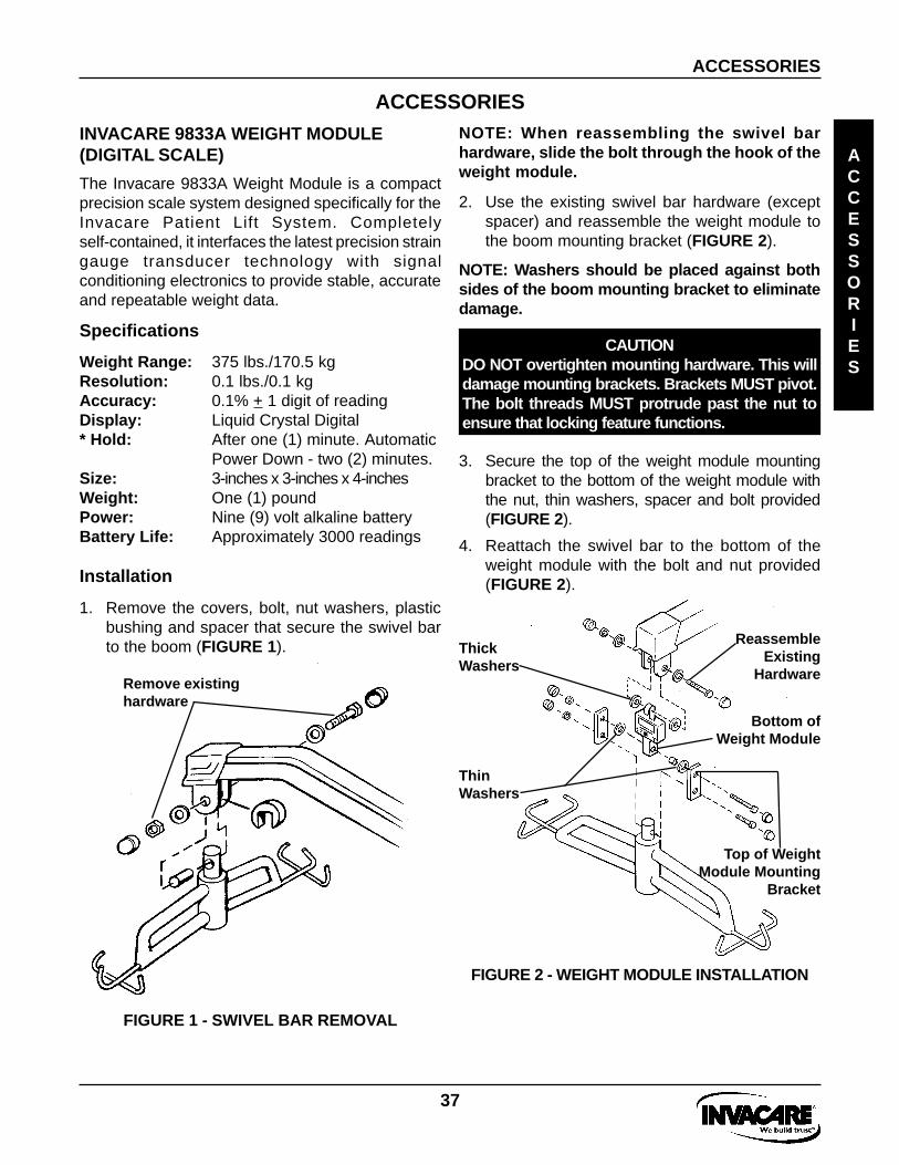
INVACARE 9833A WEIGHT MODULE(DIGITAL SCALE)
NOTE: When reassembling the swivel barhardware, slide the bolt through the hook of theweight module.
2. Use the existing swivel bar hardware (exceptspacer) and reassemble the weight module tothe boom mounting bracket (FIGURE 2).
NOTE: Washers should be placed against bothsides of the boom mounting bracket to eliminatedamage.
CAUTIONDO NOT overtighten mounting hardware. This willdamage mounting brackets. Brackets MUST pivot.The bolt threads MUST protrude past the nut toensure that locking feature functions.
ACCESSORIES
The Invacare 9833A Weight Module is a compactprecision scale system designed specifically for theInvacare Patient Lift System. Completelyself-contained, it interfaces the latest precision straingauge transducer technology with signalconditioning electronics to provide stable, accurateand repeatable weight data.
Specifications
Weight Range: 375 lbs./170.5 kgResolution: 0.1 lbs./0.1 kgAccuracy: 0.1% + 1 digit of readingDisplay: Liquid Crystal Digital* Hold: After one (1) minute. Automatic
Power Down - two (2) minutes.Size: 3-inches x 3-inches x 4-inchesWeight: One (1) poundPower: Nine (9) volt alkaline batteryBattery Life: Approximately 3000 readings
Installation
1. Remove the covers, bolt, nut washers, plasticbushing and spacer that secure the swivel barto the boom (FIGURE 1).
FIGURE 1 - SWIVEL BAR REMOVAL
Remove existinghardware
3. Secure the top of the weight module mountingbracket to the bottom of the weight module withthe nut, thin washers, spacer and bolt provided(FIGURE 2).
4. Reattach the swivel bar to the bottom of theweight module with the bolt and nut provided(FIGURE 2).
ACCESSORIES
ReassembleExisting
Hardware
ThickWashers
ThinWashers
Top of WeightModule Mounting
Bracket
Bottom ofWeight Module
FIGURE 2 - WEIGHT MODULE INSTALLATION

38
ACCESSORIES
Operating Instructions
1. Set the lbs./kg switch to the desired mode.
2 With the swivel bar and sling attached to theweight module, press the OPERATE button onthe front panel and adjust to ZERO by rotatingthe adjustment knob until you obtain a displayedreading of 00.0.
NOTE: The swivel bar and sling can also beweighed separately, then subtracted from thetotal weight which includes the patient andattaching hardware.
3. Place the patient in the sling.
4. Lift the patient to a height sufficient enough toensure that the patient is not in contact with thebed, chair, etc.
5. When the patients motion has stabilized, pressthe OPERATE button and the patient's weightwill be displayed.
NOTE: The weight module will automatically turnOFF after approximately two (2) minutes toconserve power. If the display turns OFF beforeyou are able to record the patients weight,simply press the OPERATE button once again.
6. Carefully lower the patient after reading.
HOLD FUNCTION. With the HOLD switch in theHOLD ON position, the display reading will FREEZEafter approximately one (1) minute (lbs./kg will flash)then automatically turn off at the end of the two (2)minute timing cycle.
Battery Replacement
The weight module is powered by a nine (9) voltbattery. This should provide approximately 3000readings before needing replacement.
When battery replacement is needed, a B willappear on the display.
Simply remove the two (2) screws on the sides ofthe module and slide the housing upward to accessthe battery.
CAUTIONCalibration and maintenance should beperformed by trained factory personnel ONLY.The load cell transducer contains no userserviceable components. In the event ofunauthorized tampering, warranties shallbecome null and void.
ACCESSORIES
ACCESSORIES

39
PLEASE NOTE: THE WARRANTY BELOW HAS BEEN DRAFTED TO COMPLY WITH FEDERAL LAWAPPLICABLE TO PRODUCTS MANUFACTURED AFTER JULY 4, 1975.
This warranty is extended only to the original purchaser/user of our products.
This warranty gives you specific legal rights and you may also have other legal rights which varyfrom state to state.
Invacare warrants the products manufactured to be free from defects in materials and workmanshipfor a period of three (3) years on the lift and one (1) year on the slings, hydraulic pump/electricactuator from the date of purchase. If within such warranty period any such product shall be provento be defective, such product shall be repaired or replaced, at Invacare’s option. This warranty doesnot include any labor or shipping charges incurred in replacement part installation or repair of anysuch product. Invacare’s sole obligation and your exclusive remedy under this warranty shall belimited to such repair and/or replacement.
For warranty service, please contact the dealer from whom you purchased your Invacare product. Inthe event you do not receive satisfactory warranty service, please write directly to Invacare at theaddress on the back cover, provide dealer’s name, address, and the date of purchase, indicate natureof the defect.
Invacare Corporation will issue a serialized return authorization. The defective unit or parts MUST bereturned for warranty inspection using the serial number, when applicable as identification within 30days of return authorization date. Do not return products to our factory without our prior consent.C.O.D. shipments will be refused; please prepay shipping charges.
Limitations and Exclusions: The foregoing warranty shall not apply to serial numbered products ifthe serial number has been removed or defaced, products subjected to negligence, accident,improper operation, maintenance or storage, products modified without Invacare’s express writtenconsent (including, but not limited to, modification through the use of unauthorized parts orattachments; products damaged by reason of repairs made to any component without the specificconsent of Invacare, or to a product damaged by circumstances beyond Invacare’s control, and suchevaluation will be solely determined by Invacare. The warranty shall not apply to problems arisingfrom normal wear or failure to adhere to the instructions in this manual.
THE FOREGOING WARRANTY IS EXCLUSIVE AND IN LIEU OF ALL OTHER EXPRESS WARRANTIES.IMPLIED WARRANTIES, IF ANY, INCLUDING THE IMPLIED WARRANTIES OF MERCHANTABILITYAND FITNESS FOR A PARTICULAR PURPOSE, SHALL NOT EXTEND BEYOND THE DURATION OFTHE EXPRESSED WARRANTY PROVIDED HEREIN AND THE REMEDY FOR VIOLATIONS OF ANYIMPLIED WARRANTY SHALL BE LIMITED TO REPAIR OR REPLACEMENT OF THE DEFECTIVEPRODUCT PURSUANT TO THE TERMS CONTAINED HEREIN. INVACARE SHALL NOT BE LIABLEFOR ANY CONSEQUENTIAL OR INCIDENTAL DAMAGES WHATSOEVER.
Some states DO NOT allow exclusion or limitation of incidental or consequential damage, orlimitation on how long an implied warranty lasts, so the above exclusions and limitations may notapply to you.
This warranty shall be extended to comply with state or provincial laws and requirements.
LIMITED WARRANTY
WARRANTY
LIMITED WARRANTY

899 Cleveland Street * P.O. Box 4028 * Elyria Ohio 44036 * Phone 1-(800) 333-6900
Form No. 95-144 P/N 270167 Printed in U.S.A.