manualslib - makes it easy to find manuals online! · it is intended to pull or carry tractor...
TRANSCRIPT

ST460
OPERATOR'S MANUAL
MODEL
Downloaded from www.Manualslib.com manuals search engine

0- 1
TO THE OWNER This manual contains information concerning the adjustment and maintenance of your SHIBAURA Model ST460. You have purchased a dependable machine, but only by proper care and operation can you expect to receive the performance and long service built into this tractor. Please have all operators read this manual carefully and keep it available for ready reference. If you lose or damage this manual, ask a new manual to SHIBAURA dealer right away. This machine was designed to power and propel itself. It is intended to pull or carry tractor attachments or load and move materials when equipped with a front end loader with a variety of buckets. Only attachments recommended and approved by SHIBAURA should be used with your tractor. Your SHIBAURA dealer will instruct you in the general operation of your tractor. (Refer to the "Delivery Report" at the back of this manual.) Your dealer's staff of factory-trained service technicians will be glad to answer any questions that may arise regarding the operation of your tractor. Your SHIBAURA dealer carries a complete line of genuine SHIBAURA service parts. These parts are manufactured and carefully inspected to insure high quality and accurate fitting of any necessary replacement parts. Be prepared to give your dealer the model and serial number of the tractor, when ordering parts. Locate these numbers now and record them below. Refer to the "General Information" section of this manual for the location of the model and serial numbers of your tractor. Model Serial Number
CAUTION
This safety alert symbol indicates important safety messages in this manual. When you see this symbol, carefully read the message that follows and be alert to the possibility of personal injury or death.
CAUTION
Pictures in this manual may show protective shielding open or removed to better illustrate a particular feature or adjustment. Be certain, however, to close or replace all shielding before operating the machine.
IMPROVEMENTS SHIBAURA, Corp. is continually striving to improve its products. We reserve the right to make improvements or changes when it becomes practical and possible to do so, without incurring any obligation to make changes or additions to the equipment sold previously.
Downloaded from www.Manualslib.com manuals search engine

0- 2
CONTENTS GENERAL INFORMATION AND SAFTY ············································································· 1-1
CONTROLS, INSTRUMENTS AND OPERATION ································································ 2-1
LUBRICATION AND MAINTENANCE ·················································································· 3-1
SPECIFICATIONS ················································································································ 4-1
INDEX·································································································································· 4-12
PRE-DELIVERY SERVICE ································································································· 4-15
PRE-DELIVERY CHECKLIST ····························································································· 4-17
Downloaded from www.Manualslib.com manuals search engine

1-1
SECTION 1
GENERAL INFORMATION AND SAFTY
GENERAL INFORMATION
PLEASE READ CAREFULLY:
For a complete list of the pre-delivery service checks performed by your dealer, refer to the PRE-DELIVERY SERVICE check list found at the back of this manual. Keep one copy as your record of the service performed. The other should be removed from the manual and kept by your dealer. MAKE SURE THAT BOTH COPIES ARE COMPLETED AND THAT YOU AND THE DEALER SIGN BOTH COPIES. After you have operated your tractor for fifty hours, take this manual and your tractor to your dealer. He will then perform the factory recommended 50-HOUR SERVICE as listed on the lower portions at the back of this manual — without charge — except for lubricant, oil, or filters replaced as part of normal maintenance. MAKE SURE THAT YOU AND THE DEALER SIGN BOTH COPIES. A PRODUCT IDENTIFICATION PLATE is located on the right-hand side of the front frame. The numbers on the plate are important should your tractor require future service. For your convenience, have your dealer record the numbers in the appropriate spaces below. SHIBAURA policy is one of continuous improvement, and the right to change prices, specification or equipment at any time without notice is reserved. All data given in this manual is subject to production variations. Dimensions and weights are approximate only and the illustrations do not necessarily show tractors in standard condition. For exact information about any particular tractor please consult your SHIBAURA Tractor Dealer.
Downloaded from www.Manualslib.com manuals search engine

1-2
CLEANING THE TRACTOR
Your tractor is a state-of-the-art machine with sophisticated, electronic controls. This should be taken into consideration when cleaning the tractor, particularly if using a high-pressure washer. Even though every precaution has been taken to safeguard electronic components and connections, the pressure generated by some of these machines is such that complete protection against water ingress cannot be guaranteed.
When using a high pressure washer, do not stand too close to the tractor and avoid directing the jet at electronic components, electrical connections, breathers, seals, filler caps, etc. Never direct a cold-water jet at a hot engine or exhaust. SERVICE PARTS
It should be pointed out that genuine parts have been examined and approved by the Company. The installation and/or use of ‘non-genuine’ products could have negative effects upon the design characteristics of your tractor and thereby affect it’s safety. The Company is not liable for any damage caused by the use of ‘non--genuine’ parts and accessories. Only genuine SHIBAURA replacement parts should be used. The use of non-genuine parts may invalidate legal approvals associated with this product. It is prohibited to carry out any modifications to the tractor unless specifically authorized, in writing, by the After Sales Service department of the Company.
Electro-magnetic Interference (EMC)
This tractor complies strictly with the European Regulations on electro-magnetic emissions. However, interference may arise as a result of add-on equipment, which may not necessarily meet the required standards. As such interference can result in serious malfunction of the unit and/or create unsafe situations, you must observe the following: Ensure that each piece of non-SHIBAURA
equipment fitted to the tractor bears the CE mark.
The maximum power of emission equipment
(radio, telephones, etc.) must not exceed the limits imposed by the national authorities of the country where you use the tractor.
The electro-magnetic field generated by the
add-on system should not exceed 24V/m at any time and at any location in the proximity of electronic components.
Failure to comply with these rules will render the SHIBAURA warranty null and void
Downloaded from www.Manualslib.com manuals search engine

1-3
METRIC BOLT TORQUE SPECIFICATION
Bolt Size Grade No.
Coarse Thread Fine Thread
Pitch (mm) Pounds-Feet Newton Meters Pitch (mm) Pounds-Feet Newton-Meters
M6
4T
1.0
3.6 – 5.1 4.9 – 6.9
– – – 7T 6.1 – 8.3 8.3 – 11.3
10T 8.7 – 11.6 11.8 – 15.7
M8
4T
1.25
9.4 – 12.3 12.7 – 16.7
1.0
11.2 – 14.8 15.2 – 20.1
7T 16.6 – 21.0 22.6 – 28.4 19.5 – 25.3 26.5 – 34.3
10T 21.0 – 26.8 28.4 – 36.3 22.4 – 29.7 30.4 – 40.2
M10
4T
1.5
18.8 – 24.6 25.5 – 33.3
1.25
21.0 – 26.8 28.4 – 36.3
7T 32.5 – 41.2 44.1 – 55.9 36.2 – 46.3 49.0 – 62.8
10T 39.8 – 51.4 53.9 – 69.6 42.7 – 54.2 57.9 – 73.5
M12
4T
1.75
27.5 – 34.7 37.3 – 47.1
1.25
31.8 – 40.5 43.1 – 54.9
7T 48.5 – 61.5 65.7 – 83.4 55.0 – 69.4 74.5 – 94.1
10T 68.0 – 85.4 92.2 – 116 73.1 – 93.3 99.0 – 127
M14
4T
2.0
46.3 – 59.3 62.8 – 80.4
1.5
51.4 – 64.4 69.6 – 87.3
7T 76.7 – 96.9 104 – 131 86.1 – 109 117 – 148
11T 102 – 129 139 – 175 108 – 137 147 – 186
M16
4T
2.0
63.6 – 81.0 86.3 – 110
1.5
67.3 – 84.6 91.2 – 115
7T 110 – 136 149 – 184 116 – 142 157 – 192
11T 152 – 188 206 – 255 163 – 199 221 – 270
M18
4T
2.0
83.9 – 104 114 – 141
1.5
96.9 – 120 131 – 163
7T 145 – 174 196 – 235 170 – 206 230 – 279
11T 203 – 246 275 – 333 221 – 271 299 – 368
M20
4T
2.5
106 – 132 144 – 179
1.5
127 – 156 172 – 211
7T 177 – 213 240 – 289 203 – 246 275 – 333
11T 268 – 325 363 – 441 293 – 358 397 – 485
Downloaded from www.Manualslib.com manuals search engine

1-4
PRECAUTIONARY STATEMENTS PERSONAL SAFETY
Throughout this manual and on machine decals, you will find precautionary statements (“CAUTION”, ”WARNING”, and “DANGER”) followed by specific instructions. These specifications are intended for the personal safety of you and those working with you. Please take the time to read them.
The word “CAUTION” is used where a safe behavioral practice according to operating and maintenance instructions and common safety practices will protect the operator and others from accident involvement.
The word “WARNING” denotes a potential or hidden hazard, which has a potential for serious injury. It is used to warn operators and others to exercise every appropriate means to avoid a surprise involvement with machinery.
The word “DANGER” denotes a forbidden practice in connection with a serious hazard.
Failure to follow the “CAUTION”, “WARNING”, and “DANGER” instructions may result in bodily injury or death.
MACHINE SAFETY Additional precautionary statements ’’NOTE”, ”ATTENTION” and ”IMPORTANT” are followed by specific instructions. These statements are intended for machine safety. NOTE: This text stresses a correct operating technique or procedure. ATTENTION: The word “ATTENTION” is used to warn the operator of potential machine damage if a certain procedure is not followed. IMPORTANT: The word "IMPORTANT" is used to inform the reader of something he needs to know to prevent minor machine damage if a certain procedure is not followed.
INFORMATION NOTE: Instructions used to identify and present supplementary information.
Downloaded from www.Manualslib.com manuals search engine
1-5
SAFETY PRECAUTIONS
A careful operator is the best operator. Most accidents can be avoided by observing certain precautions. To help prevent accidents, read the following precautions before operating this equipment. Equipment should be operated only by those who are responsible and instructed to do so. Carefully review the procedures given in this manual with all operators. It is important that all operators be familiar with and follow safety precautions. THE TRACTOR 1. Read the Operator's Manual carefully before
using the tractor. Lack of operating knowledge can lead to accidents.
2. Only allow properly trained and qualified
persons to operate the tractor. 3. Use an approved roll bar for safe operation.
Overturning a tractor without a roll bar can result in death or injury. If your tractor is not equipped with a roll bar, see your SHIBAURA Dealer.
4. Always use the seat belt. The only instance
when the seat belt should not be used is if the roll bar has been removed from tractor or folding ROPS is in down position.
5. If a front-end loader is to be installed, always
use a FOPS (Falling Object Protective Structure) canopy to avoid injury from falling objects.
6. Use the handholds and step plates when
getting on and off the tractor to prevent falls. Keep steps and platform cleared of mud and debris.
7. Do not permit anyone but the operator to ride
on the tractor. There is no safe place for extra riders.
8. Keep all safety decals clean of dirt and grime,
and replace all missing, illegible, or damaged safety decals. See the list of decals in the decal section of this manual.
9. Install all guards before starting the engine or
operating the tractor.
DRIVING THE TRACTOR 1. Always sit in the driver’s seat while starting or
driving the tractor. Do not start the engine or operate controls while standing beside the tractor.
2. When driving on public roads, have
consideration for other road users. Pull in to the side of the road occasionally to allow any following traffic to pass. Do not exceed the legal speed limit set in your country for agricultural tractors.
3. Dip the tractor lights when meeting a vehicle
at night. Make sure the lights are adjusted to prevent blinding the driver of an oncoming vehicle.
4. Reduce speed before turning or applying the
brakes. Brake both wheels simultaneously when making an emergency stop. Ensure that both brake pedals are locked together when traveling at road speeds or when on public roads to ensure correct operation of trailer brakes, balanced operation of the tractor brakes.
5. Use extreme caution and avoid hard
application of the tractor brakes when towing heavy loads at road speeds.
6. To avoid overturns, drive the tractor with care
and at a safe speed. Use extra caution when operating over rough ground, when crossing ditches or slopes, and when turning corners.
7. Use extreme caution when rise the front-end
loader or the three-point linkage implements. In these conditions, the center of gravity of the tractor may transfer to upward and tractor may roll over, earlier than expected.
Downloaded from www.Manualslib.com manuals search engine

1-6
8. Keep the tractor in the same gear when going downhill as used when going uphill. Do not coast or free wheel down hills.
9. Any towed vehicle with a total weight
exceeding that of the towing tractor must be equipped with brakes for safe operation.
10. Never apply the differential lock when turning.
When engaged, the differential lock will prevent the tractor from turning.
11. If the tractor becomes stuck or the tires
become frozen to the ground, reverse the tractor to prevent overturning.
12. Always check overhead clearance, especially
when transporting the tractor. Watch where you are going, especially at row ends, on roads, around trees and low hanging obstacles.
13. Use extreme caution when operating on
steep slopes. OPERATING THE TRACTOR 1. Before starting the tractor, apply the parking
brake, place the PTO control in the "OFF" position, the lift control lever in the down position, the remote control valve levers in the neutral position, and the transmission in neutral.
2. Always sit in the tractor seat when starting the
engine or operating controls. Do not start the engine or operate controls while standing beside the tractor.
3. Do not bypass the neutral start switches.
Consult your SHIBAURA dealer if your neutral start controls malfunction.
4. Use jumper cables only in the recommended
manner. Improper use can result in tractor runaway.
5. Avoid accidental contact with the gearshift
lever while the engine is running. Unexpected tractor movement can result from such contact.
6. Before leaving the tractor, park the tractor on level ground, apply the parking brake, lower the attached implements to the ground, disengage the PTO, and turn the engine off. Never get off the tractor while it is in motion.
7. Do not park the tractor on a steep incline. 8. Do not run the tractor engine in an enclosed
building without adequate ventilation. Exhaust fumes can cause death or illness.
9. If the power steering or engine ceases
operating, stop the tractor immediately. 10. Pull only from the drawbar or the lower link
drawbar in the down position. Use only a drawbar pin that locks in place. Pulling from the tractor rear axle or any point above the axle may cause the tractor to overturn.
11. Always set the hydraulic selector lever in
position control when attaching or transporting equipment. Ensure hydraulic couplers are properly mounted and will disconnect safely in case of accidental detachment of implement.
12. If the front end of the tractor tends to rise
when heavy implements are attached to the three-point hitch, install front end or front wheel weights. Do not operate the tractor with a light front end.
13. Engage the clutch slowly when driving out of
a ditch, gully or up a steep hillside. Disengage the clutch promptly if the front wheels rise off the ground.
14. Ensure any attached equipment or
accessories are correctly installed, are approved for use with the tractor, do not overload the tractor and are operated and maintained in accordance with the instructions issued by the equipment or accessory manufacturer.
Downloaded from www.Manualslib.com manuals search engine

1-7
15. Remember that your tractor, if abused or incorrectly used, can be dangerous and become a hazard both to the operator and to bystanders. Do not overload or operate with attached equipment which is unsafe, not designed for the particular task or is poorly maintained.
16. Do not leave equipment in the raised
position. 14. Do not operate the tractor or any attachments
while under the influence of alcohol, medication, and controlled substances or when tired.
15. Use the flasher/turn signal lights when
traveling on public roads both day and night (unless prohibited by law).
16. Do not drive equipment near open fires. 17. Always wear a protective mask when working
with toxic spray chemicals. Follow the directions on the chemical container.
18. Keep children(person) away from the tractor
and farm machinery at all times. OPERATING THE POWER TAKE OFF (PTO) 1. When operating PTO-driven equipment, shut
off the engine, switch off the PTO and wait until the PTO stops before getting off the tractor and disconnecting the equipment.
2. Do not wear loose clothing when operating
the power take-off or when near rotating equipment.
3. When operating stationary PTO driven
equipment, always place both gearshift levers in neutral, apply the tractor parking brake, and block the rear wheels front and back.
4. To avoid injury, DO NOT clean, adjust,
unclog, or service the PTO driven equipment when the tractor engine is running or all movement components have not completely stopped. Ensure that the PTO is switched off.
5. Ensure the PTO master shield is installed at all times. Always replace the PTO shield cap when the PTO is not in use.
SERVICING THE TRACTOR
1. Before servicing the tractor, park it firm, flat and level surface, set the parking brake, lower all implements to the ground, place the gear shift lever in neutral, stop the engine and remove the key.
2. To avoid sparks from an accidental short
circuit, always disconnect the battery's ground cable (-) first and reconnect it last.
3. To prevent the serious personal injury or
damage to the tractor, DO NOT use the worn tools or inappropriate tools for the required application or job.
3. The cooling system operates under pressure
which is controlled by the radiator cap. It is dangerous to remove the cap while the system is hot. Always turn the cap slowly to the first stop and allow pressure to escape before removing the cap entirely.
4. Keep any type of open flame away from the
tractor and do not smoke while refueling. Wait for the engine to cool before refueling.
5. Keep the tractor and equipment, particularly
brakes and steering, maintained in a reliable and satisfactory condition to ensure your safety and comply with legal requirements.
6. Keep open flame or cold weather starting
aids away from the battery to prevent fires or explosions. Use jumper cables according to instructions to prevent sparks which could cause explosion.
Downloaded from www.Manualslib.com manuals search engine

1-8
7. Escaping hydraulic/diesel fluid under pressure can penetrate the skin causing serious injury. If fluid is injected into the skin, obtain medical attention immediately or gangrene may result.
• DO NOT use your hand to check for leaks. Use a piece of cardboard or paper to search for leaks.
• Stop the engine and relieve pressure before connecting or disconnecting lines.
• Tighten all connections before starting the engine or pressurizing lines.
8. The fuel oil in the injection system is under high pressure and can penetrate the skin. Unqualified persons should not remove or attempt to adjust a pump, injector, nozzle, or any other part of the fuel injection system. Failure to follow these instructions can result in serious injury.
9. Continuous long-term contact with used
engine oil may cause skin cancer. Avoid prolonged contact with used engine oil. Wash the skin promptly with soap and water.
9. Do not modify or permit anyone else to
modify or alter this tractor or any of its components or functions without first consulting a SHIBAURA Dealer
. 10. Do not make adjustments or repairs with
the engine running. To prevent serious injury, keep hands and clothing away from rotating fan, drive belt and drive shaft.
11. Some components on your tractor, such as gaskets and friction surfaces (brake linings, clutch linings etc.) may contain asbestos. Breathing asbestos dust is dangerous to your health. You are therefore advised to have any maintenance or repair operations on such components carried out by an authorized SHIBAURA Dealer. If, however, service operations are to be undertaken on parts that contain asbestos, the essential precautions listed below must be observed:
• Work out of doors or in a well-ventilated area. • Dust found on the unit or produced during
work on the unit should be removed by extraction not by blowing.
• Dust waste should be dampened, placed in a
sealed container and marked to ensure safe disposal.
• If any cutting, drilling, etc., is attempted on
materials containing asbestos, the item should be dampened and only hand tools or low speed power tools used.
12. Keep the area used for servicing the machine
clean and dry. Wet or oily floors are slippery. 13. Do not work under any raised attachment or
hydraulically supported devices unless a suitable hoist or floor jack securely supports it and multiple jack stands. They can settle, suddenly leak down, or be accidentally lowered.
14. The ROPS and seat belt must be properly
maintained, and must not be modified, drilled, or altered in any way. If the ROPS is damaged, it must replaced and should not be straightened or welded.
15. Keep equipment clean and properly
maintained. 16. Dispose of all drained fluids and removed
filters properly. 17. Tractor wheels are very heavy. Handle with
care and ensure, when stored, that they can not topple and cause injury.
INPORTANT: Wear suitable personal protective equipment and clothing to suit the conditions and regulations in your country. This equates but not limited to protection of eyes, lungs, ears, head, hands and feet when operating, servicing or repairing the equipment. Always keep hair and clothing away from moving parts. Do not wear loose clothing, jewelry or other items that could entangle with levers and or moving parts.
Downloaded from www.Manualslib.com manuals search engine

1-9
PREVENTION OF FIRE OR EXPLOSION 1. Due to the flammable nature of some crop
materials, the risk of tractor fire can be high. This risk can be minimised by frequent removal of accumulated crop material from the tractor. If oil leaks appear, correct the fault by re-torquing the bolts or replacing the gaskets as necessary.
2. When operating in flammable crop conditions,
check and remove all trash or debris from the tractor each day, especially around the engine area and exhaust system.
3. Sparks or open flame can cause the
hydrogen gas in a battery to explode. To prevent an explosion carry out the following:
• When disconnecting the battery cables,
remove the negative (-) cable first. When re-connecting the battery cables, connect the negative (-) cable last.
• DO NOT short-circuit the battery terminals
with a metal object. • DO NOT weld, grind or smoke near a battery. 4. Periodically check the tractor electrical
system for loose connections or frayed insulation. Repair or replace any damaged parts.
5. Sparks from the electrical system or engine
exhaust can cause an explosion and fire. Before you operate the tractor in an area with flammable dust or vapors, use a good ventilation system the remove the flammable dust or vapors.
6. Use a non-flammable cleaning solvent when
cleaning parts on the tractor. 7. A fire can cause injury or death. It is
advisable to have a fire extinguisher near or on the tractor when operating in conditions where a fire may occur. Ensure fire extinguishers are serviced according to the manufacturers instructions.
8. If a fire extinguisher has been used, always
recharge or replace the extinguisher before operating the tractor in conditions where a fire may occur.
9. DO NOT store flammable materials (oil
soaked rags etc.) on the tractor. TRANSPORT THE TRACTOR 1. To prevent the falling accident and serious
injury, before loading the tractor must be ensure that;
• Stop the engine and apply the parking brake of trailer.
• Place the tractor “Brake pedal lock plate” in the locked position
• Remove the muddy soil or debris from tractor wheels and tires.
• Keep the suitable visibility from operator seat for loading.
• Use the running board or bridge, which have suitable strength, width, and length.
• Fix the running board or bridge with trailer floor firmly and securely.
2. DO NOT make sharp turn on the running board, bridge or trailer floor when loading the tractor.
3. Keep the tractor in the same gear when loading the tractor. Do not coast or free wheel on the running board or bridge.
4. To prevent the overturn of tractor, use the reverse moving for running on uphill, and use the forward moving for running on the downhill of running board or bridge.
5. Fix the transporting tractor with trailer floor firmly and securely by suitable strength rope, hook, or chains.
6. To avoid traffic accident, Always check the overhead clearance of transporting tractor.
Downloaded from www.Manualslib.com manuals search engine

1-10
DIESEL FUEL 1. Under no circumstances should gasoline,
alcohol, or blended fuels be added to diesel fuel. These combinations can create an increased fire or explosive hazard. Such blends are more explosive than pure gasoline in a closed container such as a fuel tank. DO NOT USE THESE BLENDS.
2. Never remove the fuel cap or refuel with the
engine running or hot. 3. Do not smoke while refueling or when
standing near fuel. Keep any type of open flame away.
4. Maintain control of the fuel filler pipe nozzle
when filling the tank. 5. Do not fill the fuel tank to capacity. Allow
room for expansion. 6. Wipe up spilled fuel immediately. 7. Always tighten the fuel tank cap securely. 8. If the original fuel tank cap is lost, replace it
with SHIBAURA approved cap. A non-approved cap may not be safe.
11. Never use fuel for cleaning purposes. 12. Arrange fuel purchases so that winter grade
fuels are not held over and used in the spring.
SAFETY FRAME (ROPS) Your SHIBAURA Tractor is equipped with a safety frame. It must be maintained in a serviceable condition. Be careful when driving through doorways or working in confined spaces with low headroom. UNDER NO CIRCUMSTANCES: •. …modify, drill or alter the safety frame in any
way. Doing so may render you liable to legal prosecution.
•. …attempt to straighten or weld any part of the
safty frame or retaining brackets which have suffered damage. Doing so may weaken the structure and endanger your safety.
•. …secure any parts on the safty frame or attach
your safety frame with anything other than the special high tensile bolts and nuts specified.
•. …attach chains or ropes to the safty frame for
pulling purposes. •. …take unnecessary risks even though your
safety frame affords you the maximum protection possible.
WHENEVER YOU SEE THIS SYMBOL
IT MEANS:
ATTENTION!
BECOME ALERT!
YOUR SAFETY IS INVOLVED!
Downloaded from www.Manualslib.com manuals search engine

1-11
ECOLOGY AND THE ENVIRONMENT
Soil air, and water are vital factors of agriculture and life in general. When legislation does not yet rule the treatment of some of the substances, which are required by advanced technology, common sense should govern the use and disposal of products of a chemical and petrochemical nature. The following are recommendations, which may be of assistance: • Become acquainted with and ensure that you
understand the relative legislation applicable to your country.
• Comply with legal regulations and guidelines
for disposal of empty containers for fuel, cooling water (coolant), oil, grease; fuel/oil filters; batteries; machine itself; machine accessories; and packaging materials.
• Where no legislation exists, obtain
information from suppliers of oils, filters, batteries, fuels, antifreeze, cleaning agents, etc., with regard to their effect on man and nature and how to safely store, use and dispose of these substances. Agricultural consultants will, in many cases, be able to help you as well.
HELPFUL HINTS
1. Avoid filling tanks using cans or inappropriate pressurized fuel delivery systems, which may cause considerable spillage.
2. In general, avoid skin contact with all fuels,
oils, acids, solvents, etc. Most of them contain substances, which may be harmful to your health.
3. Modern oils contain additives. Do not burn
contaminated fuels and or waste oils in ordinary heating systems.
4. Avoid spillage when draining off used engine coolant mixtures, engine, gearbox and hydraulic oils, brake fluids, etc. Do not mix drained brake fluids or fuels with lubricants. Store them safely until they can be disposed of in a proper way to comply with local legislation and available resources.
5. Modern coolant mixtures, i.e. antifreeze and
other additives, should be replaced every two years. They should not be allowed to get into the soil but should be collected and disposed of safely.
6. Do not open the air-conditioning system
yourself. It contains gases, which should not be released into the atmosphere. Your dealer or air conditioning specialist has a special extractor for this purpose and will have to recharge the system properly.
7. Repair any leaks or defects in the engine
cooling or hydraulic system immediately. 8. Do not increase the pressure in a pressurized
circuit as this may lead to a component failure.
9. Protect hoses during welding as penetrating
weld splatter may burn a hole or weaken them, allowing the loss of oils, coolant, etc.
Downloaded from www.Manualslib.com manuals search engine

1-12
SAFTY DECALS The decals reproduced on the following pages were installed on your tractor in the positions indicated in the drawings below. They are intended for your safety and for those working with you. Please take this Manual and walk around your tractor, noting the location of the decals and their significance. Review the decals and operating instructions detailed in this Manual with the machine operators. Keep the decals clean and legible. If they become damaged or illegible, obtain replacements from your SHIBAURA dealer.
1
2
4 3
2
5 6
7
8
9
10
1
11
12
14
13 15
17 16
16
DECAL PLACEMENT GUIDE
Downloaded from www.Manualslib.com manuals search engine

1-13
1. Location:
• Left hand side fender. • Inside of hood.
WARNING: Read and understand all the warning notes printed in the Operator’s Manual. In particular, read the General Information and Safety section in the Operator’s Manual.
Part No. 390197900
2. Location: Left and right-hand side of fan guard
WARNIMG: To prevent serious injury, keep hands and clothing away from rotating fan and drive belt.
Part No. 390198020 3. Location: On the radiator cap
WARNIMG: Pressurized cooling system. Allow to cool then remove cap carefully. Using a cloth, turn cap to the first stop and allow pressure to subside before removing cap completely.
Part No. 490992490 4. Location: Beside of the radiator cap
WARNIMG: Pressurized cooling system. Allow to cool then remove cap carefully. Using a cloth, turn cap to the first stop and allow pressure to subside before removing cap completely. Part No. 390199470
Downloaded from www.Manualslib.com manuals search engine

1-14
5. Location: Front of battery stand.
DANGER: Explosive gas. Avoid any open fires. Corrosive acid. Wear eye protection.
Part No. 390199450
6. Location: Battery.
CAUTION: Comply with legal regulations and guidelines for disposal of battery.
Part No. 390199430
7. Location: Starter Motor.
WARNIMG: Do not start the engine by shorting across the starter terminals. Tractor will start in gear if normal circuitry is bypassed. NEVER start the engine while on the ground. Start engine only from operator’s seat, with transmission in neutral.
Part No. 390199520 8. Location: Air cleaner.
DANGER: Do not use ether with the grow plug starting aid or spray. Cause an explosion and fire.
Part No. 390199500
Downloaded from www.Manualslib.com manuals search engine
1-15
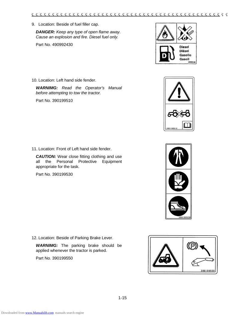
9. Location: Beside of fuel filler cap.
DANGER: Keep any type of open flame away. Cause an explosion and fire. Diesel fuel only.
Part No. 490992430 10. Location: Left hand side fender.
WARNIMG: Read the Operator’s Manual before attempting to tow the tractor.
Part No. 390199510
11. Location: Front of Left hand side fender.
CAUTION: Wear close fitting clothing and use all the Personal Protective Equipment appropriate for the task.
Part No. 390199530
12. Location: Beside of Parking Brake Lever.
WARNIMG: The parking brake should be applied whenever the tractor is parked.
Part No. 390199550
Downloaded from www.Manualslib.com manuals search engine

1-16
13. Location: Left hand side ROPS.
WARNIMG: Always turn the key to OFF position and remove it, before performing any intervention or service on the tractor; always refer to the Operator’s manual for specific information.
WARNIMG: Always wear the seat belt when the tractor is equipped with a ROPS with raised locking position.
Part No. 390199480
14. Location: Left hand side ROPS.
WARNIMG: To avoid serious injury, always raise the ROPS and lock it, when you drive or operate the tractor.
Part No. 390198011
15. Location: Rear of left hand side fender.
WARNIMG: Pull only from the drawbar. Always use the drawbar or the lower links in the lowered position, when performing pull-type work.
Part No. 390199600
Downloaded from www.Manualslib.com manuals search engine

1-17
16. Location: Right hand side ROPS.
WARNIMG: To avoid injury, do not stand on the implement or between the implement and tractor while operating the HPL lift or PTO controls. Always operate the HPL lift or PTO controls from operator seat.
Part No. 390199460
17. Location: PTO Guard.
WARNIMG: To avoid injury, DO NOT clean, adjust, unclog, or service the PTO driven equipment when the tractor engine is running or all movement components have not completely stopped. Ensure that the PTO is switched off.
Part No. 390199490
Downloaded from www.Manualslib.com manuals search engine

1-18
INSTRUCTION DECALS
Front-Wheel Drive Control Lever PART NO: 390173871 LOCATION: Lower Left Side of Operator’s Platform
Creep shift Lever PART NO: 390170680 LOCATION: Lower Left Side of Operator’s Platform
PTO speed shift Lever PART NO: 390171170 LOCATION: Left Side Control Panel
Position Control Lever PART NO: 390372490 LOCATION: In Side of Right Fender
Range Selector Lever PART NO: 390172142 LOCATION: Left Side Control Panel
PTO Mode Selector Switch PART NO: 390380950 LOCATION: Above Left Side Fender
Draft Control Lever PART NO: 390171300 LOCATION: Right Side Control Panel
Downloaded from www.Manualslib.com manuals search engine

1-19
Forward/Reverse Shuttle Lever PART NO: 390174131 LOCATION: Left Side of Dash
4-Speed Transmission Lever PART NO: 390174140 LOCATION: Right Side of Dash
Turn Signal PART NO: 390380960 LOCATION: Left Side of Dash
Road Light Switch PART NO: 390380791 LOCATION: Left Side of Dash
Road Light High Beam Switch PART NO: 390230810 LOCATION: Left Side of Dash
Throttle PART NO: 390430290 LOCATION: Right Sideof Dash
Hazard Flasher Light Switch PART NO: 390380770 LOCATION: Right Side of Dash
Hydraulic Manifold Operation (See Operator’s Manual) PART NO: SBA390198320LOCATION: Top of Hydraulic Manifold Block
Horn Switch PART NO: 390230970 LOCATION: Right Sideof Dash
Downloaded from www.Manualslib.com manuals search engine

1-20
Differential Lock PART NO: 390198301 LOCATION: Above Pedal Right Side of Operator’s Platform
Starter Switch PART NO: 390197280 LOCATION: Starter Switch, Right Side of Instrument Panel
Flow Control Valve PART NO: 390372471 LOCATION: Top of Flow Control Knob
Power Steering Fluid PART NO: 390230230 LOCATION: Top of P.S. Reservoir
Engine Oil PART NO: 390230220 LOCATION: Engine Oil Filler Cap
Rear Remote Control (Optional) PART NO: 390370300 LOCATION: Right Side Control Panel
Steering Wheel Tilt PART NO: 390198970 LOCATION: Left side of steering column shroud
Hood Latch PART NO: 390198960 LOCATION: Right side of Front Frame
Downloaded from www.Manualslib.com manuals search engine

1-21
UNIVERSAL SYMBOLS
As a guide to the operation of your tractor, various universal symbols have been utilized on the instruments, controls, switches, and fuse box. The symbols are shown below with an indication of their meaning.
Downloaded from www.Manualslib.com manuals search engine

1-22
AIRBORNE NOISE EMISSION
In accordance with E.C. directives, the noise levels of tractors covered by this Manual and marketed within the European Economic Community are as follows:
Model Transmission
Noise level at Operator’s ear *
External noise **
Closed – dB(A)
Open – dB(A)
Drive by dB(A)
Stationary dB(A)
ST460 4WD EHSS N/A 88.7 79.0 80.0 ST460 4WD SSS N/A 87.0 80.0 80.0
* Test results are in accordance with directive 2009/76/EC Annex II. ** Test results are in accordance with directive 2009/63/EC Annex VI.
HAZARDS RELATED TO VIBRATION EXPOSURE
WARNING
The Whole Body Vibration level will depend on a lot of parameters, some of them machine related, others terrain related andmany driver related.
The properties of the track or field surface and the driving speed will be the predominant parameters.
WARNING
Machine vibrations cause discomfort to the operator and in some cases his health and safety may be at risk.
Make sure the machine is in good condition and that the service interval work has been carried out correctly.
Check the tyre pressure, the steering and the brake system.
Check that the operator’s seat and adjustment controls are in good condition and then adjust the seat to suit the operator’s size and weight.
Operate all controls consistently so the machine works smoothly and modify your driving to suit working conditions.
During travel, adjust your speed and slow down if necessary.
Vibration* m/s2 at (testing mass)
Seat model Light weight operator Heavy weight operator
COBO GT50/M91 1.13 0.75
* Test results are in accordance with directive 78/764/EEC.
Downloaded from www.Manualslib.com manuals search engine

2-1
SECTION 2 CONTROLS, INSTRUMENTS AND OPERATION
SEAT AND MIRROR
Adjusting the Tractor Seat
Your SHIBAURA tractor equipped with an adjustable suspension seat.
To adjust the seat fore and aft, move the release lever ① towards the fender, slide the seat to the desired position, releasing the lever to lock.
The seat height is controlled variable by the knob ②. While sitting in the seat, turn it clockwise to increase the height, or turn it counterclockwise to reduce the height.
To adjust the seat suspension for individual operators; with moving the lever ③ straight up, turn it clockwise to be for “+” and turn it counter-clockwise to be for less “-“. Adjusting the seat belt
The male end of the seat belt ②, is part of a retraction mechanism, located on the left side of the seat. To extend the length of the seat belt, pull out on the male end until the correct length is obtained. To latch the belt, insert the male end into the belt latch ①, located on the right side of the seat. Ensure that the belt is securely latched during use, and that the belt length is correctly adjusted for the size of each operator. Use soap and water to clean the seat belt if necessary. Do not use carbon tetrachloride, naphtha, etc., as these substances will weaken the webbing. Additionally, do not bleach or re-dye the webbing, as these products will also weaken the webbing.
Replace the seat belt if it becomes damaged or worn. Operator Seat Presence Switch
The operator presence switch is located beneath the seat and is connected to the engine start and run systems.
To start the tractor the operator MUST be in the seat to energize the fuel system. If the operator leaves the seat with the engine running, the fuel system will be shut down and the engine will stop.
Downloaded from www.Manualslib.com manuals search engine

SECTION 2 – OPERATION
2-2
Adjusting the mirror
Your tractor equipped with a mirror. The mirror can be moved fore/aft or outside/inside as desired.
To adjust the mirror, loosen the screw-tightened clamp for repositioning the mirror. STEERING WHEEL Adjusting the Steering Wheel
The tractor is equipped with an adjustable steering wheel which can telescope and tilt.
To telescope the wheel, turn the wheel hub ①, counter-clockwise and raise or lower the steering wheel to the desired height. Then turn the hub clockwise to lock it into position.
NOTE: When locking the hub into position, do not over tighten.
To tilt the wheel, push forward the lever ②, and move the steering wheel forward or backward to the desired position. If the wheel is not held in position when the lever is raised, the steering wheel will spring to its most forward position. Use this feature to gain additional clearance when mounting and dismounting the tractor.
ROLLOVER PROTECTIVE STRUCTURE (ROPS)
Your tractor is equipped with a folding Roll Over protective Structure (ROPS). If, for some reason, the ROPS was deleted by the original or has been removed. It is recommended that you equip your tractor with a ROPS.
ROPS are effective in reducing injuries during tractor overturn accidents. Overturning tractor without a ROPS can result in serious injury or death.
Roll Over Protective Structure (ROPS), is available from your SHIBAURA Tractor Dealer.
Downloaded from www.Manualslib.com manuals search engine

SECTION 2 – OPERATION
2-3
WARNING
When improperly operated, a tractor can roll over. For low clearance use only, the ROPS may be lowered. No protection is provided when the tractor is operated with the ROPS in the lowered position. ALWAYS raise the ROPS and lock it immediately after low clearance work.
Folding the ROPS
A foldable ROPS is factory installed on your tractor. Operate with ROPS in the raised position whenever possible. Use the ROPS in the folded position only when absolutely necessary.
To fold the ROPS remove two lock pins, lower the upper of the ROPS rearward.
Install two lock pins to anchor the ROPS firmly once in position. To rise the ROPS reverse the above procedure.
WARNING Do not operate the tractor with the ROPS folded as a standard operating mode. A folded ROPS does not provide rollover protection.
WARNING Always wear the seat belt when the tractor is equipped with a ROPS. However, if the ROPS has been removed from the tractor, or if the ROPS is in the folded position, the seat belt should not be used.
WARNING Always pull from the tractor the drawbar. DO NOT attach chains or ropes to the ROPS for pulling purposes, as the tractor can tip backwards
WARNING When driving through door openings or under low overhead objects, make sure there is sufficient clearance for the ROPS.
Downloaded from www.Manualslib.com manuals search engine

SECTION 2 – OPERATION
2-4
INSTRUMENT PANEL
1. Cold Starting Indicator Light
Illuminate when the key switch is turned to the "HEAT" position. It remains lit for approximately 5 seconds when the key is held in position, during which time the glow plugs are heating the pre-combustion chambers. 2. Engine Oil Pressure Warning Light
Illuminates with the key switch in the "ON" or "HEAT" positions and remains lit for a short period of time after the engine is started. The light indicates oil pressure only and goes out when sufficient oil pressure is present at the oil sender. If the bulb becomes lit during operation, stop the tractor engine immediately and investigate the cause.
3. Battery Charge Warning Light
Illuminates when the key switch is in the "ON" or "HEAT" positions and goes out when the engine is started. If this bulb becomes lit during operation, it indicates that the charging system is not operating normally. As the battery can become fully discharged under these conditions, the problem should be investigated as soon as possible.
4. Proof Meter
Records the hours and portions of hours that your tractor has been operated based on an average engine speed of 3000 RPM. Engine speeds below 3000 RPM accumulate engine hours at a slower rate than clock hours. Engine speeds above 3000 RPM accumulate engine hours faster than clock hours. Use the proof meter as a guide to determine hourly service and maintenance intervals.
3 1 212 13 11
15 14
10 6 865 9
4
7 7
Downloaded from www.Manualslib.com manuals search engine

SECTION 2 – OPERATION
2-5
5. Fuel Gauge
Indicates the amount of diesel fuel remaining in the tank. The gauge is activated when the key switch is in the "ON" or "HEAT" positions. It will register empty with the key switch in the "STOP" position. 6. Flasher Hazard Warning Lights
Flash the both allow when the hazard light switch is “ON” positioned. 7. Flasher Turn Lights
Operate when the turn signal switch is activated. Rotate the switch to the right for right turns, the right arrow will flash. Rotate the switch to the left for left turns, the left arrow will flash. The flasher turn lights can be activated with the key switch in any position.
8. Temperature Gauge
Indicates coolant temperature. It is activated when the key switch is turned to the "ON" or "HEAT" positions. The gauge will register cold with the key switch in the "STOP" position. If the needle registers in the green range of the gauge, this indicates a normal operating temperature. If the needle moves to the red portion of the gauge, this indicates an overheated condition. Stop the tractor engine immediately and investigate the cause. 9. Tachometer
Registers engine RPM (Revolutions Per Minute). The gauge is marked in increments of 100 and will return to zero when the engine is not running.
10. Rear PTO Speed
Determined by the position of the needle on the tachometer. The tachometer is marked to indicate 540rpm PTO speed.
Your tractor is equipped with 2-speed PTO so that the symbol of “540” on the proof-meter relates to 540rpm PTO speed with lower PTO speed gear is selected, and “540E” symbol relates to 540rpm PTO speed with higher PTO speed gear is selected.
Engine RPM should remain close to this mark while using the rear PTO; running the engine faster than these results in a dangerous over speed condition. 11. High Beam Indicator
Illuminates when the, head-lights are switched to main beam. 12. Parking Brake Light
Illuminates if the parking brake is engaged when the key switch is turned from "OFF" position. 13. Hazard Indicator Warning Lights
Flash in unison with the flasher hazard warning light when the hazard lights switch is “ON” positioned. 14. PTO Indicator Lights
Illuminates with the key switch in the “ON” position and the PTO control switch is “ON” positioned. 15. Trailer Flasher lights burn out indicator
Flash in unison with the flasher turn lights, when burn out or wire breaking the flasher lights of trailer, which connected with ELECTRICAL SOCKET of tractor, and flasher switch is turned on.
Also, flash in unison with the flasher lights, when ELECTRICAL SOCKET of tractor is not connected with trailer, and flasher switch is turned on.
Downloaded from www.Manualslib.com manuals search engine

SECTION 2 – OPERATION
2-6
KEY SWITCH
The key switch ① is located on the right-hand side of the console, just below the hand throttle. Turning the key clockwise, to the "ON" position, activates the warning lights and instruments. The pre-heat system is activated when the key is turned farther clockwise to the "HEAT" position, and the engine starts when the key is turned to the extreme right. The key spring returns to the "ON" position when released. PRE-HEATING THE SYSTEM
Your tractor has a diesel engine. Before starting a cold engine, the pre-combustion chambers must be heated. To pre-heat the engine, turn the key switch to the "HEAT" position and hold the key in this position for approximately 5 seconds. The glow plugs heat the pre-combustion chambers during this time, and the engine will start. NOTE: When ambient temperatures are colder, a longer pre-heat time is necessary. Even after the cold start indicator light has gone out, the glow plugs will continue to heat if the key is held in the "HEAT" position.
WARNING Do not use ether with the thermostat starting aid.
OFF
ON
HEAT
START
Downloaded from www.Manualslib.com manuals search engine

SECTION 2 – OPERATION
2-7
STARTING THE ENGINE
The key switch ① allows activation of the starter motor and fuel delivery only when: The PTO control switch ③ is in the “OFF”
position.
Forward/Reverse shuttle lever ② is in the “NEUTRAL” position.
Clutch / Inching pedal ④ “FULLY” depressed.
IMPORTANT: (EHSS TRANSMISSION ONLY) The following procedures have to be performed, after starting the tractor, to allow the EHSS controller to be activated and enable the transmission to operate.
Operator in the seat.
Fully depress and release Inching pedal. NOTE: Always use safe practices when starting your tractor. Turn the key to the extreme right. Position the hand throttle forward so that it is one-fourth to one-third open.
WARNING Always sit in the operator's seat and apply the parking brake, when starting the tractor. Never attempt to start the engine while standing beside the tractor.
IMPORTANT: Do not engage the starting motor continuously for more than 30 seconds. Doing so may cause starting motor failure. The engine will shut off in approximately two seconds if the operator leaves the seat without the shuttle lever in the neutral position.
3
Downloaded from www.Manualslib.com manuals search engine

SECTION 2 – OPERATION
2-8
STARTING THE TRACTOR WITH JUMPER CABLES
WARNING Start the engine only from the operator's seat. If safety start switches are bypassed, the engine can start with the transmission and/or PTO in gear.
If it is necessary to use jumper cables to start the tractor, follow the instructions below. 1. Shield eyes.
2. Set the transmission shuttle and main shift lever are in the “NEUTRAL” position and apply the parking brake.
3. Set the PTO control switch is in the “OFF” position.
4. Connect one end of the jumper cable to the tractor battery positive ○+ terminal and the other to the auxiliary battery positive ○+ terminal. Next, connect one end of the other jumper cable first to the auxiliary battery negative ○- terminal, then the other end to the tractor starter ground terminal. Finally, start the tractor by following the safe starting procedures outlined under "Starting the Engine." Idle the engine and turn on all electrical equipment (lights, etc.), then disconnect the jumper cables in the reverse order in which they were connected. This helps protect the alternator from damage due to extreme load changes.
WARNING
Batteries contain sulfuric acid and produce explosive gases. To prevent personal injury:
• Wear eye and skin protection.
• Keep sparks and flame away.
• Ensure there is adequate ventilation while charging or using the battery.
• Follow the manufacturer's instructions found on the battery.
STOPPING THE ENGINE
Pull the hand throttle fully rearward and turn the key switch to the “OFF” position to stop the engine. After full load operation, allow the engine to run at low idle for one minute before engine shutdown. This will allow the turbocharger to reduce RPM and be properly lubricated during shutdown. IMPORTANT: The battery charge warning lights will remain on and discharge the battery if once the engine has stopped and the key switch is not turned to the “OFF” position. BREAK-IN PROCEDURES
Your SHIBAURA tractor will provide long and dependable service if given proper care during the first 50-hour break-in period. During the first 50 hours of operation: 1. Avoid "lugging" the engine. Operating in too
high a gear under heavy load may cause engine lugging, which is indicated when the engine will not respond to a throttle increase.
2. Use the lower gear ratios when pulling heavy
loads and avoid continuous operation at constant engine speeds. You will save fuel and minimize engine wear by selecting the correct gear ratio for a particular operation. Operating the tractor in low gear with a light load and high engine speed wastes fuel.
3. Avoid prolonged operation at either high or
low engine speeds without a load on the engine.
4. Check the instruments frequently and keep
the radiator and oil reservoirs filled to recommended levels. Daily checks include the engine oil level, radiator coolant, and air cleaner.
5. After the first 50 hours of use, be sure to
perform the maintenance items listed in the maintenance schedule.
Downloaded from www.Manualslib.com manuals search engine

SECTION 2 – OPERATION
2-9
LIGHTING
Your tractor equipped with: • Headlights ① • Side and Taillights / Brake Lights ② • Flasher Warning Lights / Turn Signals ③
1
3
2
Downloaded from www.Manualslib.com manuals search engine

SECTION 2 – OPERATION
2-10
Headlights and Taillights
There are headlights located in the front of the tractor hood, dual element road lights ①. The key switch must be in the “ON” position for the lights to operate.
Light Switches
Road Lights Switch ③
Rear Position “OFF”.
Mid Position Illumination of Instrument Panel and Taillights.
Front Position Illumination of Road lights, Instrument Panel and Taillights.
Road Lights High Beam Switch ④
Rear Position High Beams “OFF”.
Front Position High Beams “ON”. NOTE: The ignition key must be in the "ON" position for the lights to operate. For High Beams to be activated, the Road light switch must be in the front position.
1
Downloaded from www.Manualslib.com manuals search engine

SECTION 2 – OPERATION
2-11
Flasher Warning (Hazard) Lights
The flasher warning lights ① are activated by placing rocker switch ② in the front position. The flasher warning lights can be activated with the key switch in any position. For your protection, use the flasher warning lights when traveling on public roads, day or night. Flasher Turn Lights (Turn Signals)
The turn signal lights are activated by moving the turn signal switch ① to the left for left turns or to the right for right turns with the key switch in any position for the turn signals to operate.
1
Downloaded from www.Manualslib.com manuals search engine

SECTION 2 – OPERATION
2-12
Brake Lights
The brake lights ① are activated when the brake pedals are depressed, with the key switch in any position. The brake lights illuminating, warns anyone following the tractor, the brakes are being applied and the tractor ground speed is being reduced. Horn
To activate the horn, push the rocker switch ②. Horn can be activated with the key switch in any position. ELECTRICAL SOCKET for Trailer
A standard seven pin socket ① is provided mounted on the left side of the tractor at the rear. With reference to the picture inset, the socket connections (as viewed from the rear of the tractor) are as follows; Pin No. Wire Color Circuit
1 Green/Red L.H. Turn Signal 2 Not Used 3 Black Earth (Ground) 4 Green/White R.H. Turn Signal 5 Red R.H. Tail lights 6 Green/Orange Brake Lights 7 Red/Black L.H. Tail lights
1
Downloaded from www.Manualslib.com manuals search engine

SECTION 2 – OPERATION
2-13
THROTTLE CONTROLS
The hand throttle ① is located on the RH side of the console. Push the throttle forward to increase the engine RPM, Pull the throttle rearward to decrease the RPM.
The foot throttle ② is located on the right-hand foot platform and can be used separately, or in conjunction with the hand throttle. With the hand throttle control lever set at a selected engine rpm, the foot throttle can be used to increase engine rpm to its maximum speed. Upon release of the foot throttle, the engine speed will return to the rpm at which the hand throttle has been set, or idle if the hand throttle is not at a pre-set position.
FUEL SHUTOFF VALVE
The fuel shutoff valve ① is located in the fuel line, on top of the fuel filter. The fuel filter is located on the right-hand side of the engine. To open the fuel shutoff valve, move the handle until it points straight up and down. To close the valve, move the handle to the clockwise horizontal position. Always close the fuel shutoff valve when servicing any part of the fuel system.
SHUTOFF
OPEN
Downloaded from www.Manualslib.com manuals search engine

SECTION 2 – OPERATION
2-14
BRAKE CONTROLS
Brake Pedals
The right brake pedal controls the braking action of the right rear wheel. The left brake pedal controls the left rear wheel brake. Depress both pedals ① simultaneously to stop the tractor. To assist in making sharp turns at slow speed, depress the right or left brake pedal as required.
WARNING When operating the tractor at high speeds, never attempt to make sharp turns by using the brakes.
Brake Pedal Lock
The brake pedal lock ② is used to secure the brake pedals together. Lock the pedals together, as shown in the illustration, whenever the tractor is operated at high speeds or when the tractor is used on the highway.
PARKING BRAKE CONTROL
The parking brake ③ is used for locking the brake systems in the applied position. The parking brake should be applied whenever the tractor is parked. To apply the parking brake, pull up the lever. To release the parking brake, down the lever with pushing the release button.
3
Release button
Downloaded from www.Manualslib.com manuals search engine

SECTION 2 – OPERATION
2-15
TRANSMISSION, FRONT-WHEEL DRIVE AND P.T.O
FRONT-WHEEL DRIVE
The front-wheel drive is controlled by a lever ① located on the left lower side of operator’s platform. To engage front-wheel drive, move the lever completely upwards. To disengage front-wheel drive, move the lever fully downward. IMPORTANT: Use front-wheel drive when additional traction is required while operating on loose soil, in wet, slippery conditions, or on slopes. For normal operation on firm soil, level hard surfaces, or when roading the unit at high speeds, disengage the front-wheel drive to maximize tire and driveline life and to economize on fuel.
1
Downloaded from www.Manualslib.com manuals search engine

SECTION 2 – OPERATION
2-16
EHSS OR SSS 24 x 24 TRANSMISSION
The 24 x 24 shuttle transmission operates through the use of a inching pedal (EHSS) or clutch pedal (SSS) ① a forward / reverse shuttle lever ② a main shift lever ③ and a range speed selector lever ④ and creep shift lever ⑤. The combinations of shuttle shift, main shift, range selector, and creep shift lever selections to obtain the 24 forward and 24 reverse speeds are shown in the accompanying chart. SPEED CREEP RANGE MAIN SHUTTLE
1
C
L
1
F/R
2 2 3 3 4 4 5
M
1 6 2 7 3 8 4 9
H
1 10 2 11 3 12 4 13
H
L
1 14 2 15 3 16 4 17
M
1 18 2 19 3 20 4 21
H
1 22 2 23 3 24 4
5
Downloaded from www.Manualslib.com manuals search engine

SECTION 2 – OPERATION
2-17
TRANSMISSION SHUTTLE LEVER
(FORWARD OR REVERSE) EHSS
The shuttle shift lever ② is used to engage the transmission into the forward or reverse mode. Move the lever first upwards, then frontward for forward and rearward for reverse travel. The inching pedal does not need to be depressed while changing direction of travel with shuttle lever. The shuttle shift lever must be in the neutral (middle) position to activate the safety start system and allow the engine to start. IMPORTANT: (EHSS TRANSMISSION ONLY) The following procedures have to be performed, after starting the tractor, to allow the EHSS controller to be activated and enable the transmission to operate.
Operator in the seat.
Fully depress and release Inching pedal. IMPORTANT: If the operator leaves the seat, with the key in the “ON” position, or the tractor running, the inching pedal ① has to be fully depressed, when the operator returns to the seat, to allow the transmission to operate. NOTE: If the shuttle lever is shifted very quickly (a fraction of a second), the transmission will shift automatically into “NEUTRAL”. To reset the transmission, shift shuttle lever into the “Neutral” position then into “FORWARD” or “REVERSE”. TRANSMISSION SHUTTLE LEVER
(FORWARD OR REVERSE) (SSS)
The shuttle shift lever ① is used to engage the transmission into the forward or reverse mode while depressing the clutch pedal. Move the lever frontward for forward and rearward for reverse travel. The shuttle shift lever must be in the neutral (middle) position to activate the safety start system and allow the engine to start.
Downloaded from www.Manualslib.com manuals search engine

SECTION 2 – OPERATION
2-18
TRANSMISSION MAIN SHIFT LEVER (1st, 2nd, 3rd, 4th)
The transmission main shift lever ③ is located on the right-hand side of the dash console. A decal of the shift pattern is located on the console. Each of the three ranges and creep gear has four forward gears and four reverse gears, providing a total of twenty-four forward and twenty-four reverse speeds. IMPORTANT: The 24 x 24 transmission is synchronized, the inching or clutch pedal must be depressed to shift any of the first through fourth gears of the main transmission. The tractor motion does not need to be stopped to change gears. While shifting down on the go, shift through each main gear, (3rd to 2nd to 1st) sequence. Skipping gears while down shifting can damage components due to over speed. TRANSMISSION RANGE LEVER
(Low, Medium, High)
The range lever ④ is located by the left-hand fender. It has three range positions. Always depress the inching pedal fully and bring the tractor to a complete stop before moving the range selector. CREEP LEVER
(Creep, High) The creep gear is controlled by a lever ⑤ located on the left lower side of operator’s platform. To engage creep gear, move the lever completely upwards. To disengage creep gear, move the lever fully downward. IMPORTANT: Do not attempt to change range gears and creep gear while the tractor is moving. The range gears and creep gear are non-synchronized. The inching / clutch pedal must be depressed and the tractor motion stopped to change gear ratios with the range shift lever or the creep shift lever.
3
4
5
Downloaded from www.Manualslib.com manuals search engine

SECTION 2 – OPERATION
2-19
INCHING PEDAL (EHSS)
The foot operated inching pedal ① must be completely depressed to stop forward or reverse travel. Always depress the inching pedal fully when changing main shift, and range gears, also when engaging the creep gear, and front wheel drive. NOTE: The inching pedal controls the dump valve, via a control cable, for the hydraulic shuttle shift transmission. When the inching pedal is depressed the dump valve releases all the hydraulic pressure to the transmission hydraulic clutch packs. There is not a dry clutch located in the engine flywheel area to control transmission drive. IMPORTANT: If the operator leaves the seat, with the key in the “ON” position or the tractor running, the inching pedal ① has to be fully depressed when the operator returns to the seat, to allow the transmission to operate. CLUTCH PEDAL (SSS)
The foot operated clutch pedal ① must be completely depressed to stop forward or reverse travel. Always depress the clutch pedal fully when changing forward/reverse shuttle, main shift, and range gears, also when engaging the creep gear, and front wheel drive.
Downloaded from www.Manualslib.com manuals search engine

SECTION 2 – OPERATION
2-20
DIFFERENTIAL CONTROL
The differential lock pedal ① is located on the right-hand foot platform. The differential lock is used to obtain additional traction in wet or loose soil. When the differential lock pedal is depressed, both final drive pinion gear shafts are locked together, preventing one wheel from rotating independently of the other. Whenever one wheel begins to slip in wet or loose soil, use the lock to obtain additional traction from the opposite wheel.
WARNING Steering the tractor is very difficult with the differential locked. Do not engage the differential lock when driving the tractor on the highway, when ground speed is above 8 km/h, or when turning the tractor. If the lock is engaged when turning, a loss of steering control will result. To operate the differential lock, depress and hold the pedal down until the lock is positively engaged. It is best to engage the lock while the wheels are turning slowly to minimize shock loads to the driveline. If a wheel spins at high speed, such as on ice, reduce engine speed to idle before engaging the lock or damage may result. Release the pedal to disengage the differential lock. NOTE: In some instances, the lock may remain engaged after the pedal is released. This can occur if one rear wheel is turning at a faster speed than the other. The lock can be disengaged in one of two ways if this occurs: Decrease the drawbar pull by raising or
disengaging the implement so that neither wheel tends to slip.
--OR--
Rapidly apply and release a light braking load to the slipping rear wheel.
Downloaded from www.Manualslib.com manuals search engine

SECTION 2 – OPERATION
2-21
POWER TAKE-OFF (PTO)
The power take-off (PTO) on your tractor transfers engine power directly to mounted or trailed equipment.
All models operate through the standard 1 3/8 in. (34.9mm) diameter, 6-spline output shaft rotating at 540rpm, the speed at which most PTO driven equipment is designed to operate.
Your tractor is equipped with 2-speed PTO so that the symbol of “540” on the proof-meter relates to 540rpm PTO speed with lower PTO speed gear is selected, and “540E” symbol relates to 540rpm PTO speed with higher PTO speed gear is selected. PTO CONTROL SWITCH
To engage the rear PTO, push the PTO control switch ①, and then rotate clockwise to set the “ON” position.
To disengage the rear PTO, push the PTO control switch, and then rotate counter-clockwise to back the “OFF” position.
The PTO control switch must be in the “OFF” position to activate the safety start system and allow the engine to start. IMPORTANT: If the operator leaves the seat without the shuttle lever in the “NEUTRAL” position and with the PTO engaged, the engine will shut off in approximately two seconds. PTO MODE SELECT SWITCH
Your tractor can be select for “PTO mode ②” for TRANSMISSION PTO” and “PTO mode ①” for INDEPENDENT- PTO” by using the PTO mode select switch ③.
Transmission PTO means that the foot-operated inching / clutch pedal allows stopping the tractor and PTO motion.
Independent PTO means that it can be engaged or disengaged, whether or not the tractor is in motion.
To activate the Independent PTO, push the PTO mode select switch ③ to outside. The indicator lamp ④ on the switch tab will illuminate when independent PTO mode is activated.
1
4
3 PTO “ON”
POSITION
PTO “OFF”
POSITION
Downloaded from www.Manualslib.com manuals search engine

SECTION 2 – OPERATION
2-22
PTO SPEED SHIFT LEVER
The PTO speed shift lever ① is located by the left-hand fender. It has two PTO speed positions. Always turn “OFF” position the PTO control switch and bring the PTO drive to a complete stop before moving the PTO speed shift lever. IMPORTANT: Do not attempt to change PTO speed shift lever while the PTO is moving. The PTO speed shift gear is non-synchronized. The PTO control switch must be off positioned or inching/clutch pedal must be depressed and the PTO motion stopped to change gear ratios with the PTO speed shift lever.
PTO SHIELD AND CAP
The PTO shield ① is standard equipment. The shield is to be used with all PTO equipment. The PTO cap ② should always be installed when the PTO is not in use.
2
1
1
Downloaded from www.Manualslib.com manuals search engine

SECTION 2 – OPERATION
2-23
POWER TAKE-OFF (PTO) OPERATION
WARNING
To reduce the possibility of personal injury, comply with the following guidelines before attaching or detaching PTO equipment, and before working on or clearing PTO equipment. 1. Attaching the PTO
• Stop the engine.
• Set the parking brake.
• Disengage the PTO using the PTO speed selector lever is “NEUTRAL” position.
• Remove the PTO cap.
• Wait until the PTO shaft stops turning.
• Attach the mounted or drawn equipment.
1. Ensure that the equipment-driven shaft is properly aligned and locked to the tractor PTO drive shaft, and that the PTO shield is lowered into the guarded position.
2. With the PTO disengaged, start the engine. For mounted equipment, raise and lower the equipment to ensure there are proper clearances for operation.
3. With the transmission range lever still in neutral (N), move the PTO speed selector to the desired position.
IMPORTANT: The PTO may be damaged if the PTO speed selector lever is not fully moved to the selected positions.
4. Engage the PTO by using the PTO control switch.
NOTE: The PTO indicator light, located in the instrument panel, will illuminate when the PTO is engaged and the key switch is in the “ON” position.
5. Check the PTO-driven equipment for proper operation by gradually increasing the engine RPM with the manual throttle control.
5. If the equipment is operating properly, shift to the desired operating gear.
6. Control the PTO speed using the throttle. Never operate in an over speed condition.
PTO speeds relative to engine speeds are shown in the following tables:
Speed selector position
PTO Speed (rpm)
Engine speed (rpm)
1 540 2475
2 540 1755
2 750 2438
WARNING
Rear PTO speeds in excess of 630 PTO rpm may damage equipment that is designed for 540rpm operation and could result in personal injury to the operator or bystanders. 7. When making sharp turns with towed
equipment, or with mounted equipment in the fully raised position, disengage the PTO using the PTO control switch.
10. When traveling on highways or for any great distance, disconnect the PTO-driven shaft at the tractor PTO shaft.
11. Reinstall the PTO shaft cap whenever PTO-driven equipment is disconnected from the tractor, or when the PTO is not being used.
WARNING
To avoid inadvertent movement of PTO implement, disengage the PTO after each use.
PTO OPERATION (WITHOUT OPERATOR IN SEAT)
To operate the rear PTO without the operator being in the seat, the following operations must be performed:
• Transmission shuttle lever and main shift lever are in “NEUTRAL” position
• Parking brake in "applied" position
IMPORTANT: If the operator leaves the seat without the shuttle lever in the “NEUTRAL” position and with the PTO engaged, the engine will shut off in approximately two seconds.
Downloaded from www.Manualslib.com manuals search engine

SECTION 2 – OPERATION
2-24
EXTENSION / CLEVIS DRAWBAR
Your tractor is equipped with a extension / clevis type drawbar for towing equipment behind the tractor. This drawbar may be extended for sliding it rearward, 145 mm. IMPORTANT: When transporting equipment on highways, a safety chain with a tensile strength equal to the gross weight of the implement should always be installed between the tractor and the implement hitch.
WARNING Pull only from the drawbar. Always use the drawbar or the lower links in the lowered position, when performing pull-type work.
TOWING THE TRACTOR Place the transmission range lever in neutral, and disengage the PTO clutch lever, to tow the tractor. Do not exceed 20 KPH.
WARNING For-safety reasons, NEVER attempt to start the engine by towing. Additionally, towing the tractor on highways is NOT recommended, for safety reasons.
Downloaded from www.Manualslib.com manuals search engine

SECTION 2 – OPERATION
2-25
HOOD LATCH
As viewed from the front of tractor: 1. To raise the hood, insert the thin stick such
as screwdriver, in the hole that located under the front of right side of hood and push up the latch release rod ①, and lift the hood to its fully raised position. A hood prop rod ② holds the hood in the fully raised position.
WARNING Make sure hood prop rod ② is fully engaged in the latched position, before servicing any components that are located under the hood. 2. To close, lift hood until prop rod ② is not
holding weight of hood, then pull forward on prop rod and then lower hood until it is retained by the latch mechanism.
IMPORTANT: Do not attempt to lower the hood without moving the support link. Attempting to force the hood down can result in bending or breaking of the hood and support linkage. NOTE: Keep the latch mechanism free of dirt and debris, so the latch will operate properly.
1
Downloaded from www.Manualslib.com manuals search engine

SECTION 2 – OPERATION
2-26
DELUXE THREE-POINT LINKAGE
The tractor’s three-point linkage is used to attach three-point mounted equipment which is usually PTO operated, such as rotary mowers, tillers, flail mowers, snow blowers, etc. The three linkage points are the two lower lift arms and the top link.
The three point linkage lower arms ball ends can be rotated to either category I or II size. The top link has a category II ball end. When attaching a category I implement, install one 25 mm (0.98 in) outer diameter bushing ④ in the implement side of the top link.
A special double diameter pin ⑤ for the top link installation is standard equipment with your tractor. Use the smaller diameter end of the pin for category I implements and the larger diameter for category II implements.
NOTE: Cycle the three point linkage through the entire travel and check for any interference with rear tires. If interference is present, adjust sway bars as needed.
The three-point linkage has easy to adjust sway bars ① to control lateral movement of the lift arms. The height of the right-hand lift arm and the top link can be adjusted by turning the leveling crank ②. The flex ends of the lift arms can be adjusted by pushing down on the clamp ③, and placing the ends in the desired position.
Downloaded from www.Manualslib.com manuals search engine

SECTION 2 – OPERATION
2-27
TOOL BOX
A tool box ① with a magnetically latched lid, is located behind the seat and between the ROPS uprights. The tool box also incorporates a hanger bracket ② to support the top link of the three-point hitch, when not attached to an implement DRINK HOLDER
A drink holder ① is attached to the right side fender, for the operator's drink storage convenience.
Downloaded from www.Manualslib.com manuals search engine

2-28
TRACTOR HYDRAULICS
HYDRAULIC POWER LIFT (H.P.L.) (3 PT)
The HPL lever ① is located on the right-hand control pod. The lever controls the position of the two lift arms. To lower the lift arms, first make sure the drop rate control valve ③ is open, then move the HPL lever forward. To raise the lift arms, move the lever rearward. An adjustable stop ② is located in this quadrant for returning the lever to a preset position The hydraulic lift system provides accurate, smooth, and instant hydraulic power for raising a variety of compatible equipment whenever the engine is running. The system’s position control feature maintains the selected height or depth of three-point linkage equipment in relation to the tractor. When the hydraulic lift control lever is moved to a higher or lower setting in the quadrant, the system repositions the equipment to a higher or lower position and maintains the selected position. The hydraulic lift system is equipped with draft control.
WARNING Make sure the area is clear of people before lowering equipment.
POSITION CONTROL
Position control provides easy, accurate control of three-point linkage equipment which operates above the ground, such as sprayers, rakes, mowers, etc. It also provides uniform depth when using a blade or similar equipment on ground level. When operating in position control, there is a definite relationship between the position of the control lever in the quadrant and the position of the equipment. The lever ①, must be moved to change the position of the equipment relative to the tractor. The system will automatically maintain the equipment in the selected position.
3
Downloaded from www.Manualslib.com manuals search engine

SECTION 2 – OPERATION
2-29
DRATFT CONTROL
When operating in draft control, the draft control lever ② used to adjust sensitivity to draft loads. Once the lever is positioned, the hydraulic lift system will automatically adjust the depth of the equipment to maintain an even load on the tractor as soil conditions vary. The hydraulic system senses draft changes through changes in upper link compression. The operation of the upper link draft sensing system is described in the following paragraph. Upper Link Compression Loads: As the equipment is pulled through the soil, the draft caused by changes in soil resistance cause the draft to increase, the compression force on the upper link will also increase. These changes in upper link compression, signal the hydraulic system through internal linkage, to raise the equipment slightly to maintain uniform draft. NOTE: Remove lock pin ① , for draft control linkage to be operative.
WARNING Always lower the hydraulic lift and other hydraulic equipment before stopping the tractor.
2
Downloaded from www.Manualslib.com manuals search engine

SECTION 2 – OPERATION
2-30
TWO LEVER CONTROLS POSITION CONTROL OPERATION
Position control is obtained by placing the draft control lever ② all the way forward and then moving the outer (Position) control lever ① to position the equipment as desired. The outer (Position) lever is used to set the desired working height or depth. DRAFT CONTROL OPERATION
Draft control is obtained by placing the position control lever in the forward position. Use the draft control to adjust the draft setting by draft control lever positioning to rearward as desired (the lift system will automatically maintain the selected draft as described above).
OPERATING IN BOTH POSITION AND DRAFT CONTROL
The position control may be used together with the draft control as follow:
1. Set the position control lever ① at the maximum desire implement depth. The hydraulic system will not lower the implement below the pre-selected depth. (This will also prevent “diving” which may be encountered with light equipment, such as a rear blade, when grading or backfilling.)
2. Position to rearward the draft control lever ② for the maximum draft load (pull) desired.
The hydraulic lift system will now provide normal draft response within the range set by the position control. This adjustment provides a more uniform depth while maintaining an even pull in widely varying soil conditions.
WARNING Make sure the area is clear of people before lowering equipment.
1
2
Downloaded from www.Manualslib.com manuals search engine

SECTION 2 – OPERATION
2-31
POSITION CONTROL ADJUSTMENT Linkage Adjustments
The length of the position control rod is critical and careful adjustment must be observed for proper operation. If the control rod is adjusted too short, the control valve spool will remain in the raised position when the lift arms have reached their maximum height and the system relief valve will open to relieve hydraulic pressure. If the control rod is too long, the control valve spool will return to neutral before the lift arms reach their full height.
The position control rod should be adjusted any time the link is disconnected for service to the hydraulic system, or any time the relief valve operation is noticed while the lift arms are at the full raise position.
Adjustment Procedure
1. Loosen the locknut ① on the position control rod ② and remove the pin ③ from the link.
2. Set the control lever ④ to the highest position.
3. Start the engine. The lift arms ⑤ should raise and the relief valve should operate.
4. Move the control lever down until the relief valve ceases operation.
5. Adjust the length of the position control rod and clevis to align the pin holes. Then lengthen the rod one additional turn and install the pin. Tighten the locknut.
6. Check the operation. The relief valve should not operate when the lift arms are in the fully raised position.
Downloaded from www.Manualslib.com manuals search engine

SECTION 2 – OPERATION
2-32
DRAFT CONTROL ADJUSTMENT
NOTE: Adjust the draft rod only after completing the position control adjustment.
1. Set the draft control lever to the most sensitive “+” position of rearward.
2. Loosen the locknut ① on the draft control rod, ②.
3. Remove the cotter pin ③ and disconnect the draft control rod from the draft control arm pin, ④.
4. Open the drop rate control valve knob ⑤ to the full open position.
NOTICE: The position control lever must be in the raised position and the lift arms up.
5. Start the engine and set at 1000 - 1500 rpm.
6. Move the draft feedback rod ② rearward until the relief valve stops operating. Adjust the length of the rod to match the rod hole with the draft arm pin ④ then shorten the rod one more turn and connect the rod to the draft arm.
7. Check the adjustments as follows:
• With the engine running, move both the position control and draft control levers to the full raise position.
• The move the position control lever to the forward (down) position.
NOTE: If the lift arms do not descend or descend too slowly, shorten the draft control rod one more turn. TOP LINK MAIN SPRING ADJUSTMENT
Remove the cotter pin ① and rotate nut ② to adjust the main spring length ③ to 77 mm and secure with the cotter pin.
Downloaded from www.Manualslib.com manuals search engine
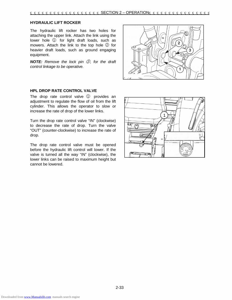
SECTION 2 – OPERATION
2-33
HYDRAULIC LIFT ROCKER
The hydraulic lift rocker has two holes for attaching the upper link. Attach the link using the lower hole ① for light draft loads, such as mowers. Attach the link to the top hole ② for heavier draft loads, such as ground engaging equipment.
NOTE: Remove the lock pin ③, for the draft control linkage to be operative. HPL DROP RATE CONTROL VALVE
The drop rate control valve ① provides an adjustment to regulate the flow of oil from the lift cylinder. This allows the operator to slow or increase the rate of drop of the lower links. Turn the drop rate control valve “IN” (clockwise) to decrease the rate of drop. Turn the valve “OUT” (counter-clockwise) to increase the rate of drop. The drop rate control valve must be opened before the hydraulic lift control will lower. If the valve is turned all the way “IN” (clockwise), the lower links can be raised to maximum height but cannot be lowered.
1
Downloaded from www.Manualslib.com manuals search engine

SECTION 2 – OPERATION
2-34
HYDRAULIC MANIFOLD BLOCK/DIVERTER VALVE
The hydraulic manifold block/diverter valve is located on the right-hand side of the tractor below the platform. The manifold block distributes pump oil to the HPL valve, optional rear remote valves, the transmission / rear axle reservoir and the valve for attached implement. The diverter valve ① can be turned with a blade screwdriver. In the 1 o’clock position, hydraulic fluid is directed to the HPL valve and rear remotes (optional). When a valve for another attached implement is plumbed to the three ports - (pressure out ② pressure return ③ and sump or tank, 4), the diverter valve must be turned counter-clockwise to 11 o’clock position for hydraulic fluid flow to the implement valve and then to the HPL valve and rear remote valve (optional). NOTE: The PTO valve, EHSS valve and power steering always receives hydraulic flow independent of the manifold block diverter setting.
Downloaded from www.Manualslib.com manuals search engine

SECTION 2 – OPERATION
2-35
REAR REMOTE CONTROL VALVE(S)
(OPTIONAL)
Your tractor can be equipped with one, two or three rear remote valves. The control lever(s) are located on the right-hand control pod, #1 remote ①, #2 remote ②, #3 remote ③. To operate the single-spool valve, pull the control lever rearward to extend the cylinder. Push the control lever forward to retract the cylinder. Release the control lever to stop the cylinder in any position. The lever automatically returns to neutral. The rear remotes are equipped with 1/2” quick couplers. ① - #1 Valve ② - #2 Valve ③ - #3 Valve NOTE: The lever automatically returns to neutral, when the cylinder reaches the limit of its stroke in either direction of travel.
WARNING Before disconnecting cylinders or equipment, make sure that the implement or equipment is supported securely. Remote couplers must be properly mounted and securely fastened to the tractor-mounting bracket for proper functioning of the safety disconnect feature.
SWITCHING BETWEEN SINGLE AND
DOUBLE ACTING CYLINDERS
To switch a single acting cylinder to a double acting cylinder, tighten the switching valve adjustment screw completely. To switch a double acting cylinder to a single acting cylinder, unscrew the adjusting screw.
3 2
1
1
3
2
Downloaded from www.Manualslib.com manuals search engine

SECTION 2 – OPERATION
2-36
DRIVING THE TRACTOR
WARNING
Observe the following precautions when driving the tractor.
Watch where you are going—especially at row ends, on roads, and around trees.
Keep the tractor in gear when going down hill.
Use a low gear to maintain control with minimum braking.
If the tractor is stuck, back out to prevent
upsetting the unit. Always use the drawbar for pull-type work.
Do not pull from any other part of the tractor, especially ROPS since it may tip backward.
Keep the lights adjusted so they do not blind
the operator of an oncoming vehicle. Engage the clutch slowly when driving out of
a ditch, gully, or up a steep hillside. Disengage the clutch promptly should the front wheels rise off the ground.
Reduce speed before turning quickly or
applying the brakes. Brake both wheels simultaneously when making an emergency stop.
Never apply the differential lock when
turning. Use extreme caution and avoid hard
applications of the tractor brakes when pulling heavy towed loads at road speeds.
Always sit in the driver's seat while starting
or driving the tractor.
Any towed vehicle whose total weight exceeds that of the towing tractor must be equipped with brakes for safe operation.
Always check overhead clearance,
especially when transporting the tractor. IMPORTANT: When transporting on the highway, it is recommended that a safety chain with tensile strength equal to the gross weight of the implement be connected between the tractor and the towed implement. This will control the implement in the event the hitch pin is lost. NOTE: Attaching hardware will need to be procured locally. Check implement assembly or operators manual for attaching hardware specifications, such as bolt size and grade, chain strength, washers, lock-washer, nuts, etc. After attaching the safety chain, make a trial run by driving the tractor to the right and to the left for a short distance to check the safety chain adjustment. If necessary, readjust to eliminate tight or loose chain. Safety chains and suitable hardware are available from your SHIBAURA Tractor Dealer
Downloaded from www.Manualslib.com manuals search engine

SECTION 2 – OPERATION
2-37
WHEEL TREAD SETTINGS
NOTE: Tread settings are measured from center of tire to center of tire. Front Wheel Settings
Tire Type Setting Note
(AG) 8 - 16 1335 mm Not Adjustable
(AG) 9.5 - 16 1442 mm Not Adjustable
(TURF) 27 x 10.5 - 15 1462 mm Not Adjustable
(AG) 260/70R16 1442 mm Not Adjustable
IMPORTANT: Never attempt to widen the tread setting by reversing the front wheels on a front-wheel drive system. NOTE: Torque front wheel bolts to 175 N ·m. Rear Wheel Settings
Tire Type MIN (DISH IN) MAX (DISH OUT) NO. OF POSITION
(AG) 13.6 - 28 1240 mm 1942 mm 8
(AG) 14.9 - 28 1338 mm 1942 mm 7
(TURF) 475/65D20 N/A 1382 mm 1
(AG) 380/70R28 1338 mm 1942 mm 7
NOTE: Torque rear wheel bolts to 175 N·m. Torque rim to disc bolts to 230 N·m
Downloaded from www.Manualslib.com manuals search engine

SECTION 2 – OPERATION
2-38
Position Rear FWD Tire Dimensions, mm Tire Type Inside To Inside Tread Setting Outside To Outside
A 905 1240 1575
(AG) 13.6 - 28
B 1003 1338 1673 C 1109 1444 1779 D 1207 1542 1877 E 1305 1640 1975 F 1403 1738 2073 G 1509 1844 2179 H 1607 1942 2277
A N/A N/A N/A
(AG) 14.9 - 28
B 958 1338 1718 C 1064 1444 1824 D 1162 1542 1922 E 1260 1640 2020 F 1358 1738 2118 G 1464 1844 2244 H 1562 1942 2322
A N/A N/A N/A
(AG) 380/70R28
B 949 1338 1727 C 1055 1444 1833 D 1153 1542 1931 E 2029 1640 2029 F 2127 1738 2127 G 1455 1844 2233 H 1553 1942 2331
918 1382 1846 (TURF) 475/65D20
Downloaded from www.Manualslib.com manuals search engine

2-39
TRACTOR WEIGHTING
For sufficient traction and maximum performance in heavy draft operations, and to counterbalance rear-mounted equipment, weight should be added to tractor in the form of liquid ballast, cast iron weights or a combination of both. Only enough weight should be added to provide good traction and stability. Adding more weight than is needed results unnecessary soil compaction, increased rolling resistance, and higher fuel consumption. NOTE: When adding weight to the tractor, tire pressures may need to be increased. Refer to the Tire Inflation Pressure chart found in page 2-41 of this manual. WEIGHTING FOR STABILITY
Front end ballast may be required for stability and steering control when weight is transferred from the front wheels to the rear wheels as an implement is raised by the tractor three-point hitch. As a general guide: Ballast the tractor (less implement) so that approximately one-third of the tractor weight is on the front wheels. For optimum traction, tractors equipped with front-wheel drive should be ballasted so that 40-45% of machine weight is on the front wheels.
When a mounted implement is raised to the transport position, the front wheel reaction should be at least 20% of tractor weight. Add additional front end ballast as required for stability during operation and transport. Tractor front end ballast may not always maintain satisfactory stability if the tractor is operated at high speed on rough terrain. Reduce tractor speed and exercise caution under these conditions. When using front-mounted equipment, add weight to the rear axle of the tractor to maintain good traction and stability. Front-mounted equipment varies in weight. Refer to equipment manual for ballasting. WEIGHTING LIMITATIONS
The weighting limitations that follow are limitations only. They do not imply that the tractor should be weighted to attain the weights given. Use only enough weight to obtain good performance.
Downloaded from www.Manualslib.com manuals search engine

SECTION 2 – OPERATION
2-40
CAST IRON WEIGHTS (OPTIONAL)
Cast iron weights are available as accessories from your SHIBAURA Dealer. Weights can be mounted on the front end of the tractor and on the rearmost wheels. Front End Weights
Tire Type Weight(s)
Agricultural and Turf Maximum of (2) weights per tractor @ 30 kg each 60 kg total
Optional Front Weight Extension Bracket
If additional front weights are needed for counterbal- ancing a rear mounted implement, an optional front weight extension bracket ①, (#372200190) can be installed to the front of the tractor. With the extension bracket installed, a maximum of (5) 30kg ② weights can be installed. Rear Wheel Weights
Tire Type Weight(s)
Agricultural tire only Maximum of (4) weights per tractor @ 30 kg each 120 kg total
Downloaded from www.Manualslib.com manuals search engine

SECTION 2 – OPERATION
2-41
LIQUID BALLAST (OPTIONAL)
It is a common practice to add weight to the tractor by filling rear tires with liquid. A calcium chloride (CaCl2) and water solution is recommended due to its low freezing point and greater density (weight per volume) than pure water. Never exceed the total recommended weight for the tractor. Because special equipment is required to fill the tires, consult your SHIBAURA Dealer.
Tires should never be filled beyond 75%. At 75% full, the liquid will come to the valve stem when the valve stem is at its highest point at the top of the wheel. TIRE PRESSURE
Tire pressure must be considered when adding weights, implements, or attachments to the tractor or damage to the tractor may occur. The chart below outlines tire inflation pressures.
FRONT TIRE INFLATION PRESSURES
Tire Type Tire Size Inflation Pressure
AG 8-16 140 – 240 kPa
AG 260/70R16 140 – 220 kPa
AG 9.5-16 140 – 215 kPa
TURF 27x10.5-15 120 – 210 kPa
REAR TIRE INFLATION PRESSURES
Tire Type Tire Size Inflation Pressure
AG 13.6-28 80 – 160 kPa
AG 380/70R28 80 – 140 kPa
AG 14.9-28 80 – 140 kPa
TURF 475/65D20 80 – 140 kPa
NOTE: Do not underinflate or overinflate tires. Do not exceed maximum inflation pressure listed.
Downloaded from www.Manualslib.com manuals search engine

SECTION 2 – OPERATION
2-42
Downloaded from www.Manualslib.com manuals search engine

3-1
SECTION 3
LUBRICATION AND MAINTENANCE Adequate lubrication and maintenance on a regular schedule is vital to maintaining your equipment. To ensure long service and efficient operation, follow the lubrication and maintenance schedules outlined in this manual. The use of proper fuels, oils, grease and filters, as well as keeping the systems clean, will also extend machine and component life.
IMPORTANT: Always use genuine SHIBAURA replacement parts, oils and filters to ensure proper operation, filtration of engine and hydraulic systems. See your SHIBAURA dealer for additional oil quantities.
GENERAL INFORMATION
Regular lubrication is the best insurance against delays and repairs. Proper lubrication will extend machine life. Refer to the following charts for lubricants and service intervals.
IMPORTANT: Failure to complete the required maintenance at the recommended intervals can cause unnecessary downtime.
The intervals listed in the Lubrication Chart are guidelines to be used when operating in normal conditions. Adjust the intervals for operating in adverse environmental and working conditions. The intervals should be shortened for sandy, dusty and extremely hot operating conditions.
CAUTION
Observe these safety precautions before performing lubrication and maintenance. 1. Ensure the unit is on level ground. 2. Shut off engine. 3. Disengage all drives. 4. Lower all attachments to the ground or
raise and engage all locks 5. Close all shields opened and reinstall any
shields removed for lubrication and maintenance proposes.
CAUTION
Some illustrations in this manual show shields opened or removed to show areas being serviced. Replace all shields before operating this machine. Always clean the area around dipsticks, fill caps, and check plugs when checking fluid levels. Failure to clean these areas may allow contamination to enter the system. Drain, flush and refill the system anytime you suspect it is contaminated. Grease Fittings
Wipe dirt from fittings before greasing. Pump fresh grease into fitting to adequately lubricate the component and force out any contamination from the grease passage. Wipe off excess grease. Use a grease gun containing clean high grade of multipurpose grease. Chains
Stop all drives before lubricating chains.
Downloaded from www.Manualslib.com manuals search engine

SECTION 3 – LUBRICATION AND MAINTENANCE
3-2
LUBRICATION AND MAINTENANCE CHART
SHIBAURA ST460 – FRONT-WHEEL DRIVE
NO. LUBRICATION &
MAINTENANCE ITEMS
CH
EC
K
CL
EA
N
LU
BE
CH
AN
GE
AD
JUS
T
SERVICE INTERVALS
1 2 3 4 5
Engine Oil Level Air Cleaner Radiator Coolant Transmission Oil Level Radiator Prescreen
××××
×
Every 10 Hoursor Daily
6 1, 7 8
11 24 -
23 27 28 29 30
Hydraulic Filter Engine Oil & Filter Tire Pressure Fuel Filter Element Wheel Bolt Torque All Fluid Levels Brake Pedal Free Play HPL Delivery Line Filter EHSS Delivery Line Filter PTO Delivery Line Filter ROPS and Mounting Bolts Torque
×
×××××××
××
××
×
×
First 50 Hours
8 9
10 12 13 14 15
16 17 18 19 20 21 22
Tires Clutch/Inching Pedal Battery Power Steering Oil Level Fan Belt Front Axle Oil Level Final Reduction Gear Cases Oil Level Lubrication Fittings: Steering Linkage 3-Point Linkage Brake Pedal Power Steering Cylinder Pedal Shaft Drive Cover Shaft Pivot Shaft
×××××××
×
×××××××
×Every
50 Hours
1, 7 2
11
Engine Oil & Filter Air Cleaner Element Fuel Filter
××
× Every 100 Hours
NO.LUBRICATION &
MAINTENANCE ITEMS
CH
EC
K
CL
EA
N
LU
BE
CH
AN
GE
AD
JUS
T
SERVICE INTERVALS
23111324 30
Brake Pedal Free play Fuel Filter Element Fan Belt Wheel Bolt Torque ROPS and Mounting Bolts Torque
× ×
×
×
×
Every 200 Hours
4 6
14 15
27 28 29
Transmission Oil Hydraulic Filter Front Axle Oil Final Reduction Gear Cases Oil HPL Delivery Line Filter EHSS Delivery Line Filter PTO Delivery Line Filter
× × ×
××××
Every 300 Hours
12 25 26
Power Steering Oil & Filter Fuel Injector Valve Clearance
× ×
×××
Every 600 Hours
2 3
Air Cleaner Radiator Coolant
××
Seasonal
2 Safety Air Filter Element × Every 3rd Primary Element
Change or Every 1000
Hours, Whichever
Comes First
8 8
28
2729 30
Downloaded from www.Manualslib.com manuals search engine

SECTION 3 – LUBRICATION AND MAINTENANCE
3-3
LUBRICATION FITTINGS
NOTE: After every 50 hours of normal operation, apply a good quality grease to the lubrication points listed below (refer to the Recommended Lubricants chart). When operating under extremely dirty conditions, lubricate more frequently than every 50 hours.
• Steering Linkage
• Front Axle Pivot
• Power Steering Cylinder
• Pedal Shaft—Clutch & Brake Pedals
• 3-Point Linkage
To lubricate these points:
1. Wipe away all old grease and dirt from the lubrication fittings to prevent dirt or foreign material from entering as new grease is applied.
2. Use a high pressure grease gun to force in the new grease. Apply pressure until clean grease oozes from each lubrication point.
3. Wipe away any excess grease.
DIESEL FUEL
• Use clean, quality No. 1 -D or No. 2-D fuel (ASTM D975).
• Use No. 1-D fuel if the ambient temperature is expected to be lower than 4°C or if the tractor is to be used at an altitude exceeding 1524 m.
• Use No. 2-D diesel fuel with a pour point of at least -12°C below the expected ambient temperature to prevent fuel flow problems in cold weather.
• Keep dirt from entering the fuel tank.
• Sulfur content of the fuel should be no more than 0.5%.
• Sediment and water content should not exceed 0.05%.
• Minimum cetane number is 40. Low temperature or high altitude operation may require use of fuel with a higher cetane number.
• Use properly mixed winter fuel when temperatures are extremely cold. In most areas, diesel fuel is properly blended for summer and winter grades as ambient
temperatures change. In winter, use winter grade diesel fuel only. Otherwise, the fuel may jell and block the fuel system.
Fuel Usage Safety • UNDER NO CIRCUMSTANCES should
gasoline, alcohol, or gasohol be added to diesel fuel. These combinations can create an increased fire or explosive hazard.
• Never remove the fuel cap or refuel the tractor while the engine is running.
• Never smoke while refueling or anywhere near fuel.
• When filling the tank, maintain control of the nozzle.
• Do not fill the fuel tank to capacity. Allow room for expansion.
• Wipe up spills immediately.
• Always tighten the fuel cap securely.
• If the original fuel tank cap is lost, always replace it with a SHIBAURA approved cap. A "will-fit" cap may not be safe.
• Keep equipment properly maintained.
• Do not drive equipment near open fires.
• Never use gasoline for cleaning parts.
Biodiesel Fuel
The use of biodiesel blends meeting Specification Standards ASTM 6751 or EN14214 are approved for your engine up to B5 (5%blend ratio). It is highly recommended to use biodiesel fuel from accredited suppliers to maintain quality and consistency of the fuel.
Biodiesel does not have a long-term stability and should not be left in engines or stored for more than four months. If your machine is stored for long term, engine should be flushed, prior to storage, by running for a minimum of 30 minutes with conventional diesel fuel.
Biodiesel fuel has a higher cloud point than conventional diesel fuels and is not recommended in winter months. Consult your fuel dealer for winter fuel requirements for your area.
Biodiesel fuel attracts moisture and may contain a higher content of water. It may be necessary to drain the fuel filter water trap more frequently.
Downloaded from www.Manualslib.com manuals search engine

SECTION 3 – LUBRICATION AND MAINTENANCE
3-4
WARNING
Fuel oil in the injection system is under high pressure and can penetrate the skin. Unqualified persons should not remove or attempt to adjust a pump injector, nozzle, or any part of the fuel injection system.
• Do not use your hand to check for leaks. Use a piece of cardboard or paper to search for leaks.
• If any fluid is injected into the skin, obtain medical attention immediately or gangrene may result.
Failure to follow these instructions can result in serious injury. Refueling the Tractor
The fuel tank filler cap ① is located at the rear of the front food. Before removing the cap, wipe all dust and dirt from around the cap to prevent debris from falling into the tank during filling. Use an approved container and check the inside of the container periodically for cleanliness. The tractor fuel tank capacity is 54 L.
NOTE: The fuel cap is a vented-type. Use only an approved SHIBAURA replacement cap to prevent fuel system-related problems. If there is no filter on the storage tank or fuel container, filter the fuel through a 100-mesh or finer screen when filling the tractor fuel tank. Keep the tractor tank as full as possible (without overfilling) to minimize condensation.
NOTE: It is a good practice to fill the fuel tank at the end of each day, as this will reduce overnight condensation.
Downloaded from www.Manualslib.com manuals search engine

SECTION 3 – LUBRICATION AND MAINTENANCE
3-5
LUBRICANTS
Type of lubricant to use, Transmission, Rear Axle, Final Reduction, and Hydraulic System
(For SSS) ········· SAE 80 (For EHSS) ·· ISO VG 46
Front Axle, Final Reduction Oil ················ SAE 80 Power Steering Oil ······························ ISO VG46 Engine Crankcase ··················· Service Grade CD
SAE 10W30, for year around use or
SAE 20W for use -5°C–25°C SAE 30 for use 10°C–35°C
All Lubrication Fittings ········· NLG 1 GRADE 2 EP
GREASE WITH LTIUM SOAP
NOTE: Use the following chart to determine which SAE Grade engine oil to use: In areas where prolonged periods of extreme temperatures are encountered, local lubricant practices are acceptable, such as the use of SAE 5W (CC) in extremely cold temperatures or the use of SAE 40 (CD) or SAE 50 (CD) in extremely high temperatures.
IMPORTANT: Engine crankcase oil drain intervals should be adjusted downward when diesel fuel sulfur content is over 0.5%. Consult your SHIBAURA dealer for details of Engine Crank case Oil usage.
Downloaded from www.Manualslib.com manuals search engine

SECTION 3 – LUBRICATION AND MAINTENANCE
3-6
FUEL AND LUBRICANT SERVICE PROCEDURES
ENGINE
Checking the engine oil level
NOTE: Check the engine oil level daily, or after every 10 hours of operation.
1. After the engine has been stopped for a
period of time, and with the tractor standing level, check the oil level using the dipstick ①.
2. If the oil level is low, remove the filler cap ②
and add oil through the filler hole. Add enough oil so that the level registers between the two marks on the dipstick. Do not overfill.
Changing the Engine Oil
NOTE: Change the engine oil and filter after the first 50 hours of operation, then every 100 hours thereafter. If the tractor is operated for extended periods of time at maximum rated power and speed, or under other types of continuous, severe operating conditions, the engine oil and filter should be changed at 70-hour Intervals following the initial oil change.
To change the engine oil: 1. Place a suitable container beneath the drain
opening to catch the used oil. With the tractor engine off but at normal operating temperature, remove the drain plugs ③ . Reinstall the plugs after all of the oil has been drained.
NOTE: Remove both drain plugs to properly drain all oil.
CAUTION
Engine oil could be hot, use caution during draining.
Downloaded from www.Manualslib.com manuals search engine

SECTION 3 – LUBRICATION AND MAINTENANCE
3-7
2. Next, Place a suitable container below the oil filter ① to catch the used oil and unscrew the oil filter. Discard the used oil and filter.
3. Coat the gasket on the new filter with a thin film of new oil. Screw the filter into place until the gasket contacts its mating surface, then turn the filter approximately three-quarters of a turn BY HAND. DO NOT over tighten.
4. Add the proper type and amount of new oil, then start the engine and check the filter for leaks. The crankcase capacity (with filter) on these tractor models is 7.0L.
NOTE: Your tractor is originally shipped with 10W-30 engine oil.
Downloaded from www.Manualslib.com manuals search engine

SECTION 3 – LUBRICATION AND MAINTENANCE
3-8
FUEL FILTER
Draining the Fuel Filter
NOTE: The fuel filter should be drained after every 100 hours of operation.
1. Make sure there is adequate fuel in the fuel
tank and close the fuel shutoff valve ① (the handle should be pointing to the "OFF" position). Remove the fuel sediment bowl ②.
2. Open the fuel shutoff valve until all water has been removed and only fuel flows from the filter base.
3. Install the fuel sediment bowl and bleed the system as outlined in "Bleeding the Fuel System."
NOTE: Valve is shown in open position.
Changing the Fuel Filter
NOTE: Change the diesel fuel filter after the first 50 hours of operation, then following every 200 operating hours thereafter.
1. Close the shutoff valve (the handle should be
pointing to the "OFF" position).
2. Remove the sediment bowl ① by rotating the retaining nut ②.
3. Open the fuel shutoff valve ③ to drain any remaining water from the tank.
4. Discard the old element ④ and install a new element.
5. Inspect the O-rings ⑤ and ⑥ and replace if necessary.
6. Install spring ⑦ between bottom of element and bowl.
7. Install and securely tighten the sediment bowl.
8. Open the fuel shutoff valve (the handle should be pointing to the "ON" position) ③ so fuel will flow to the filter.
9. Bleed the fuel filter and injection pump as described next in "Bleeding the Fuel System."
Downloaded from www.Manualslib.com manuals search engine

SECTION 3 – LUBRICATION AND MAINTENANCE
3-9
Bleeding Air From the Fuel System
The vehicle has an auto-bleed system, which should exhaust all air if the engine is cranking.
The system should bleed with minimal cranking if the sediment bowl is filled with fuel.
If the bowl is slow in filling, there is likely a blockage in the return vent lines.
Manually bleed the fuel system if:
• It has been drained.
• A new filter element has been installed.
• The tractor has run out of fuel.
• The lines leading to or from the filter have been disconnected.
• The injection pump has been removed and reinstalled.
WARNING
Fuel oil in the injection system is under high pressure and can penetrate the skin. Unqualified persons should not remove or attempt to adjust a pump injector, nozzle, or any part of the fuel injection system.
• Do not use your hand to check for leaks Use a piece of cardboard or paper to search for leaks.
• If any fluid is injected into the skin, obtain medical attention immediately or gangrene may result.
Failure to follow these instructions can result in serious injury.
Downloaded from www.Manualslib.com manuals search engine

SECTION 3 – LUBRICATION AND MAINTENANCE
3-10
To bleed the fuel system:
1. Make sure there is adequate fuel in the fuel tank.
2. Open the fuel shutoff valve ①.
3. Remove hose ②, from the top of the bleed fitting. Reinstall hose when air-free fuel starts to flow.
4. Push the hand throttle to the high-speed position. Turn the engine over for a few seconds to bleed the high-pressure fuel tubes.
Bleeding the Injector Lines
Bleed the injector lines if:
• The tractor has run out of fuel.
• New injectors have been installed.
• The injection pump has been removed for service repairs.
To bleed the injector lines:
1. Loosen the injector line fittings ① at the injectors.
2. Move the hand throttle control lever to its wide open position.
3. Crank the engine until air-free fuel flows from each connection, then tighten the fittings to 24-29 N·m.
IMPORTANT: If air is not purged from the system, repeat the above procedures.
Do not crank the engine continuously for more than 30 seconds as this may cause starter motor failure.
Downloaded from www.Manualslib.com manuals search engine

SECTION 3 – LUBRICATION AND MAINTENANCE
3-11
AIR CLEANER
The air cleaner ① is accessed by opening the tractor hood. The air cleaner assembly contains two elements: an outer (primary) element, and an inner (safety) element.
To remove the primary element, release the clips ② on the end cap. Remove the end cap from the air cleaner body to expose the primary element ③.
Downloaded from www.Manualslib.com manuals search engine

SECTION 3 – LUBRICATION AND MAINTENANCE
3-12
Air Cleaner Primary Element
NOTE: Clean the primary element after every 100 hours of service. Extremely dusty conditions may require more frequent service intervals.
1. Pull the primary element ③ from the canister. Clean any loose dirt from the canister and inspect the end of the canister for dirt, which may prevent the new element from sealing properly.
2. Clean the primary element using low air pressure (200kPa or less). Blow dust from the inside to the outside of the element (opposite to normal air flow through element).
IMPORTANT: Be careful not to rupture the filter element. Maintain a safe distance between the air nozzle and the filter element when directing air up and down the clean air side of the element pleats.
3. After cleaning the element, check the inner diameter seals for damage. If damage is present, replace the primary element.
4. Reinstall the primary element by inserting it into the canister and pushing on the end of the element until it is seated against the canister.
NOTE: Place a light inside the element to check for paper leaks or for bonding of the paper to the end plate. If any leaks are found, replace the element.
NOTE: If element is not inserted far enough into canister, the end cap cannot be installed.
5. Place the end cap onto the canister body, push in on end cap, and rotate clockwise. Make sure the end cap is locked in place and not loose.
IMPORTANT: Never tap the element with hard objects or against a hard surface. This may dent or break the element end cap seals.
IMPORTANT: Failure to obtain a good seal between elements and the canister may cause major engine damage.
Downloaded from www.Manualslib.com manuals search engine

SECTION 3 – LUBRICATION AND MAINTENANCE
3-13
Air Cleaner Inner Safety Element
NOTE: For maximum engine protection and air cleaner service life, install a new inner safety element every third primary element change or after every 1000 hours of operation, whichever comes first.
The air cleaner inner safety element ④ cannot be cleaned. It must be replaced once it becomes partially clogged. A clogged element will cause an air restriction resulting in a loss of engine power or excessive black exhaust smoke.
NOTE: Conduct a visual inspection of the inner safety element by placing a light inside the element. Little or no light will shine through the element if it is partially clogged.
To remove the inner safety element, pull it out of the canister body.
To install the new element, push it into the canister until seated.
IMPORTANT: Clean any dirt from the canister before installing the inner safety element. Check element inner diameter seals for damage and replace the safety element if seal damage is present.
IMPORTANT: Failure to obtain a good seal between the filter and canister may cause major engine damage.
Downloaded from www.Manualslib.com manuals search engine

SECTION 3 – LUBRICATION AND MAINTENANCE
3-14
TRANSMISSION, REAR AXLE, AND
HYDRAULIC SYSTEM
Checking the Transmission, Rear Axle, and
Hydraulic System Oil Level
NOTE: Check the transmission, rear axle, and hydraulic system oil level after every 50 hours of operation. 1. With the engine off and the tractor standing
level, check the oil level using the dipstick ①. 2. The oil is at the correct level when it reads
between the two marks on the dipstick. If the level is low, remove the filler plug ①, and add new oil of the type specified, page 3-5, through the filler hole. Do not fill above the dipstick full mark.
3. Reinstall the filler plug and dipstick.
HYDRAULIC SYSTEM OIL FILTER
NOTE: Replace the hydraulic system oil filter after the first 50 hours of operation, and then following every 300 hours of operation thereafter. The hydraulic system uses a spin-on type oil filter. To replace the filter ①: 1. Unscrew the used oil filter and discard. 2. Coat the gasket on the new filter with a film of
clean oil. Screw the filter into place until the gasket contacts the sealing surface, then tighten the filter by hand approximately three-quarters of a turn. Do not over-tighten.
3. Start the engine and check the filter for leaks. 4. Stop the engine and check the hydraulic
system oil level. Add oil if necessary.
Downloaded from www.Manualslib.com manuals search engine

SECTION 3 – LUBRICATION AND MAINTENANCE
3-15
Changing the Transmission, Rear Axle, and Hydraulic System Oil
NOTE: Change the transmission, rear axle, and hydraulic system oil after every 300 hours of operation.
NOTE: During cold weather operation, tractor hydraulic oil can be changed to ISO VG 46 oil is a multiviscosity oil which has improved flow characteristics in low temperatures and can be used year round.
1. Place a suitable container beneath the
transmission ① and rear axle drain plug ② to catch the used oil. With the oil at normal operating temperature, drain the system by removing the transmission and rear axle drain plugs. Reinstall the drain plugs after all of the oil has drained out. Discard the used oil properly.
2. Remove the filler plug ③ and fill with new oil
of the type specified page 3-5. The transmission is filled to the correct level when the oil registers between the two marks on the dipstick. Do not fill above the dipstick full mark.
Capacity and oil grade: transmission:
EHSS 46 L / ISO VG46
SSS 38 L / SAE 80 3. Reinstall the dipstick and filler plug.
IMPORTANT: There is a common sump for the transmission, rear axle, and hydraulic system. Therefore, extra care should be taken to keep the oil clean.
Downloaded from www.Manualslib.com manuals search engine

SECTION 3 – LUBRICATION AND MAINTENANCE
3-16
POWER STEERING
Checking the Power Steering Oil Level
NOTE: Check the power steering oil level after every 50 hours of operation.
1. With the tractor standing level and the engine off, check the oil level using the dipstick ①.
2. The oil is at the correct level when it reads between the full mark and the lower end of the dipstick. If capacity is low, add ISO VG 46 hydraulic oil through the combined dipstick/filler plug. Do not overfill the reservoir.
3. Reinstall the dipstick/filler plug.
Changing the Power Steering Oil
NOTE: Change the power steering oil/filter after every 600 hours of operation.
1. Place a suitable container beneath the power steering reservoir to catch the used oil. With the oil at normal operating temperature, drain the power steering reservoir by removing the drain plug that located at bottom of filter flange. Reinstall the plug once the oil has drained and discard the used oil.
2. Rotate counter-clockwise to remove the filter/ reservoir assembly.
3. Coat the gasket on the new filter with a film of clean oil. Screw the filter into place until the gasket contacts the sealing surface, then tighten the filter by hand approximately three-quarters of a turn. Do not over-tighten.
4. Remove the filler plug/dipstick and fill with ISO VG 46 hydraulic oil. The oil reservoir is filled to the correct level when the level reads between the full mark and the lower end of the dipstick. Do not fill above the full mark.
5. Reinstall the dipstick/filler plug.
Downloaded from www.Manualslib.com manuals search engine

SECTION 3 – LUBRICATION AND MAINTENANCE
3-17
GENERAL MAINTENANCE
COOLING SYSTEM
The tractor engine must operate at the correct temperature to obtain maximum efficiency and service life. This is dependent on the cooling system. Always fill the system with a 50/50 solution of ethylene glycol antifreeze and water.
Checking the Coolant Level
NOTE: Check the coolant level daily or after every 10 hours of operation. The engine should be cold when coolant level is checked. 1. Visually inspect the coolant level in the over
flow tank ①.
WARNING
The cooling system operates under pressure controlled by the radiator cap. It is dangerous to remove the cap while the system is hot. Always cover the cap with a thick cloth and turn it slowly counter-clockwise to the first stop. Allow all pressure to escape before removing the cap completely.
2. If the coolant level is below the cold level line ②, remove overflow tank cap ③, add a 50/50 solution of ethylene glycol anti-freeze and water solution as necessary. Plain water will dilute the solution and weaken its protection.
3. Remove the two wing nuts that retain the front radiator screen and slide the screen ④, out the left side of the tractor.
4. Keep the radiator fins ⑤, clear of chaff or dirt to allow free air movement.
5. EHSS transmission only, there is an oil cooler ⑥ , located in front of the radiator and underneath air cleaner. Keep fins of cooler clean of any buildup of material, so that transmission oil can be cooled.
Downloaded from www.Manualslib.com manuals search engine

SECTION 3 – LUBRICATION AND MAINTENANCE
3-18
Draining and Flushing the Cooling System
NOTE: Drain and flush the radiator and engine block every 12 months. Refill with a 50/50 mixture of ethylene glycol antifreeze and clear water.
To drain the cooling system:
1. Use a suitable receptacle to catch the used coolant. Remove the radiator cap and open the drain valve ① on the right-hand side of the tractor frame, to drain the radiator and drain valve ②, on right side of engine block to drain engine block.
2. After the coolant has drained, place a water hose in the radiator filler neck and run water through the system. When water is flowing from the block drain valve, start the engine. When the water flowing from the drain valve is free of discoloration and sediment, stop the engine and remove the hose. Allow all water to drain from the system through the drain valves.
3. Close the drain valve and slowly refill the system with a 50/50 solution of ethylene glycol antifreeze and water. Fill until the coolant level is same the bottom of the filler neck. Do not fill beyond this level.
4. Clean the radiator cap and cap seal and install the cap.
5. Run the engine until normal operating temperature is reached, then stop the engine. Recheck the coolant level when the engine is cold and add additional coolant as necessary.
IMPORTANT: Never run the engine when the cooling system is empty. Do not add cold water or cold antifreeze solution if the engine is hot.
WARNING
The cooling system operates under pressure controlled by the radiator cap. It is dangerous to remove the cap while the system is hot. Always cover the cap with a thick cloth and turn it slowly counter-clockwise to the first stop. Allow all pressure to escape before removing the cap completely.
Downloaded from www.Manualslib.com manuals search engine

SECTION 3 – LUBRICATION AND MAINTENANCE
3-19
Thermostat
The thermostat ① , is a heat-sensitive valve located in the coolant outlet connection in the front of the cylinder head.
When the engine is cold, the thermostat shuts off the flow of coolant to the radiator, allowing for rapid engine warm-up. A recirculating bypass allows coolant to circulate inside the engine whenever the thermostat shuts off flow to the radiator. IMPORTANT: Do not attempt to improve cooling by removing the thermostat. This will cause the engine to run below normal working temperatures, resulting in excessive engine wear.
To install a new thermostat ①, position it in the recess of the water outlet connection so that the heat element (spring end) is in the cylinder head of the engine. Fan Belt
NOTE: Check the condition of the fan beIt after every 50 hours of operation. Check fan belt tension after every 200 hours of operation.
A belt-driven fan located at the front of the engine draws air through the fins of the radiator to lower the temperature of the radiator coolant.
When 5 kg of thumb pressure is applied to the belt midway between the belt pulleys, a correctly tightened belt will deflect 5 - 10 mm.
If the fan belt is slipping, fan efficiency is lowered, resulting in the engine running too hot. If the belt is too tight, the life of the alternator bearing will be shortened. If the fan belt shows signs of cracking or fraying, install a new belt. To adjust fan belt tension:
WARNING
Never attempt to loosen or tighten mounting bolts while the engine is running.
1. Loosen the alternator mounting bolts ①.
2. Pry the alternator away from the engine and tighten the mounting bolts.
3. Recheck belt deflection.
Downloaded from www.Manualslib.com manuals search engine

SECTION 3 – LUBRICATION AND MAINTENANCE
3-20
MAINTENANCE AND INSPECTION OF THE ROLLOVER PROTECTIVE STRUCTURE
(ROPS)
NOTE: Inspect the ROPS after the first 50 hours of operation. Following the initial inspection, check the ROPS after every 200 hours of operation or every six months, whichever comes first.
1. Check the torque of the ROPS mounting bolts, ①. Tighten the bolts ①, to the correct torque of 74.5 N·m and nuts ②, 108 N·m.
POSSIBLE DAMAGE TO THE ROPS
If the unit has rolled over or the ROPS has been in some other type of accident (such as hitting an overhead object during transport), the ROPS must be replaced to retain the best protection. Following an accident, check the ROPS, the operator's seat for possible damage. Before operating the machine, replace all damaged parts.
IMPORTANT: Do not attempt to weld or straighten the ROPS.
WARNING
Always pull from the tractor drawbar pin hole. Never attach chains, ropes, or cables to the ROPS or cab for pulling purposes or the tractor will tip backwards.
WARNING
If the ROPS or cab is removed or replaced, make sure that the proper hardware is used and the recommended torque values are applied to the attaching bolts.
Always wear your seat belt unless the tractor is not equipped with a ROPS or folding ROPS is in the down position. In this case, the seat belt should not be worn.
Downloaded from www.Manualslib.com manuals search engine

SECTION 3 – LUBRICATION AND MAINTENANCE
3-21
BATTERY
The tractor is equipped with a 12-volt battery, with a minimum cold cranking ability of 700 amps at -18ºC. Keep the battery connections tight and free of corrosion. An ammonia or baking soda-water solution is good for washing the outside surface and terminals of the battery. After cleaning, wash the battery with clean water. Apply a small amount of petroleum jelly to the terminals to protect them from corrosion. In freezing temperatures, a good battery charge must be maintained. If the battery becomes discharged or run down, the electrolyte becomes weak and may freeze, causing damage to the case. If you must add water, use distilled water. Add the water just before using the tractor so that the water will mix with the electrolyte during the charging process, thus preventing the water from freezing.
Checking the Electrolyte Level and Gravity
NOTE: Check the battery electrolyte level after every 50 hours of operation.
To determine the battery charge, check the indicator (Hydrometer) on this battery as following shows.
Blue: Good condition, the level and gravity of electrolyte are good.
Red: Necessary to charge, electrolyte is week.
White: Add the distilled water, water level is low.
Never over charge the battery, it could cause an explosion and the battery may be discharged or run down.
Charge the battery within 10% of the rated 6.5 amps.
WARNING
Always check the electrolyte level and gravity with the tractor engine off, as an explosive gas is produced inside the battery when the alternator is charging. Do not use an exposed flame and do not smoke when checking the battery electrolyte level and gravity.
To add the distilled water:
1. Clean the top of the battery, then remove the vent plugs.
2. Add distilled water if the electrolyte level is low. The level is correct when the liquid is 6.35 mm above the plates.
NOTE: Keep distilled water in a nonmetallic container that is clean and well-covered. 3. Install the vent plug after making sure the
vent holes are not blocked. At below freezing temperatures, run the engine for a period of time after adding water, allowing the battery to charge, which prevents the water from freezing.
INDICATOR
Downloaded from www.Manualslib.com manuals search engine

SECTION 3 – LUBRICATION AND MAINTENANCE
3-22
ALTERNATOR
The tractor's 55-amp alternator ①, is belt-driven from the engine crankshaft pulley. It is important that belt slippage does not occur, or the charging system will be adversely affected. To adjust the belt, see the instructions previously given under "Fan Belt" section (page 3-19). Other than belt adjustment, the only alternator maintenance required is to periodically inspect the terminals to ensure they are clean and tight. The alternator-cooling fan should also be cleaned periodically. When working on or checking the alternator, adhere to following precautions or alternator damage may occur:
• Do not UNDER ANY CIRCUMSTANCES short the field terminal of the alternator to ground.
• Do not disconnect the alternator output lead or battery cables while the alternator is operating.
• Do not remove the alternator from the tractor without first disconnecting the negative (-) battery cable. When removing the battery, disconnect the negative (-) cable first.
• To install a battery, MAKE SURE that the positive (+) cable is connected first and that the negative terminal is connected to ground. Reverse polarity will destroy the rectifier diodes in the alternator.
If the battery charge warning light illuminates, indicating that the alternator is not charging the battery, check the fan belt and the wiring connections. If these items are in satisfactory condition and the warning light continues to indicate no charge, consult your SHIBAURA Dealer.
Downloaded from www.Manualslib.com manuals search engine

SECTION 3 – LUBRICATION AND MAINTENANCE
3-23
FUSE BLOCK
The fuse block is located in the engine compartment on the right side of the tractor firewall. Always replace blown fuses with the size specified for that circuit.
WARNING
Always Disconnect the negative (-) battery cable from the negative (-) battery terminal before replace the fuses. From left to right as viewed from above the tractor, the fuse block contains the following fuses:
Fuse Fuse Size
Circuit Protected
1 15A Alternator, Safety Start, Indicator Lamps, Gauges, Road Lights, Tail lights, ACC Power Relay,
2 15A Horn, Brake Lamp, PTO Valve
3 20A Turn Signal, Hazard Lights, Brake Lamp,
4 15A Work Lamp, Engine Control,
5 25A Road lights, Illumination Lamp of Instrument Panel.
MAIN FUSE
The main 40-amp fuse ① is located on the LH side of the engine, between the starter and the alternator. This fuse protects the tractor's entire electrical system.
To replace the main fuse:
1. Unplug the connector, exposing the fuse.
2. Remove the old fuse from the fuse holder and replace the new one.
IMPORTANT: Always replace this fuse with a similar 40 amp fuse; DO NOT increase the amperage rating.
WARNING
Always Disconnect the negative (-) battery cable from the negative (-) battery terminal before replace the fuses.
Downloaded from www.Manualslib.com manuals search engine

SECTION 3 – LUBRICATION AND MAINTENANCE
3-24
HEAD LAMP
If any of the two head lamps fails to operate, the bulb must be replaced. To change the bulb:
1. Open the tractor hood.
2. Disconnect the negative (-) battery cable from the negative (-) battery terminal before replace the fuses.
3. Pull up the connector ① and rubber ② the housing.
4. Take off the spring.
5. Remove the bulb.
6. Install a new bulb and install the spring, rubber and connector.
IMPORTANT: Be careful not to touch the bulb with bare fingers. Oil from the fingers can shorten the life of the bulb. Use a protective cloth or glove when installing the new bulb.
TAILLIGHT / FLASHER WARNING LIGHT/SIDE LIGHT
The tractor is equipped with two taillights ①, and four flasher-warning lights ②, and two side-lights ③, mounted on the ROPS. To replace the bulbs:
1. Disconnect the negative (-) battery cable from the negative (-) battery terminal before replace the fuses.
2. Remove the two screws securing the lens to the housing.
3. Remove the lens, and then remove the bulb.
4. Install a new bulb and reinstall the lens and/or rim assembly.
1 2
2
1
2
3
Downloaded from www.Manualslib.com manuals search engine

SECTION 3 – LUBRICATION AND MAINTENANCE
3-25
INSTRUMENT LIGHTS
To change a burned out instrument panel bulb:
1. Disconnect the negative (-) battery cable from the negative (-) battery terminal before replace the fuses.
2. Remove right rear hood ① , and left rear hood ②, by removing retaining bolts ③, ④, ⑤.
3. Remove rubber boots ⑥, and ⑦, from upper dash panel.
4. Remove throttle control knob ⑧, from lever.
5. Remove the two front retaining bolts ⑨.
6. Remove the left and right underside retaining screw ⑩, from dash panel.
7. Tilt steering wheel rearward to ease tilting of dash panel.
8. Tilt dash panel rearward to gain access to underside of instrument panel.
9. Rotate bulb 1/4 turn and remove from back of instrument panel.
10. Inspect bulb mating surface of instrument panel for corrosion and clean if necessary. Install correct size bulb and assemble the dash panel and rear hoods.
NOTE: Replace with the appropriate bulb: either a 1.7W bulb for gauge lights, a 3.4W bulb for indicator lights, or a 3.0 W bulb for PTO indicator and Trailer hazard indicator.
9
10
Downloaded from www.Manualslib.com manuals search engine

SECTION 3 – LUBRICATION AND MAINTENANCE
3-26
TIRES
NOTE: Check tire pressure after every 50 hours of operation or weekly.
Tire inflation pressure affects the amount of weight a tire can carry. Check the air pressure in your tractor tires, then locate the tires in the "Tire Inflation Pressures" chart found in this manual (page 2-41), If necessary, adjust the tire pressure, being careful not to overinflate or underinflate. Observe the following guidelines:
• Do not inflate a tire above the maximum pressure shown on the tire. If the tire is not marked, do not exceed the maximum pressure shown in the Tire Inflation chart found in this manual (page 2-41).
• Do not reinflate a tire that has been run flat or seriously underinflated until the tire has been inspected for damage by a qualified person.
• When checking tire pressure, inspect the tire for damaged sidewalls and tread cuts. Neglected damage leads to early tire failure.
WARNING
Inflating or servicing tires can be dangerous. Trained personnel should service and/or mount tires whenever possible. If you must inflate or service tires, follow these safety precautions to avoid injury or fatality:
• Make sure the rim is clean and free of rust.
• Lubricate both tire beads and rim flanges with soap solution. Do not use oil or grease.
• Use a clip-on tire chuck with a remote hose and gauge. This allows the operator to stand clear of the tire while inflating.
• NEVER INFLATE TO OVER 2.4 BAR TO SEAT BEADS. If beads have not been seated by the time pressure reaches 2.4 bar deflate the assembly, reposition the tire on the rim, relubricate both tire bead and rim flanges, and reinflate. Inflation beyond 2.4 bar with unseated beads may break the bead or rim with explosive force sufficient to cause serious injury.
• After seating the beads, adjust inflation pressure to recommended operating pressure.
• Do not inflate a tire unless the rim is mounted on the tractor or is secured so that it will not move if the tire or rim should suddenly fail.
• Do not weld, braze, repair, or use a damaged rim.
• Never attempt tire repairs on a public road or highway.
• Use jack stands or other suitable blocking to support the tractor while repairing tires.
• Ensure the jack has adequate capacity to lift your tractor.
• Place jack on a firm, level surface.
• Do not place any part of your body beneath the tractor or start the engine while the tractor is on the jack.
• Before adding ballast to the tires, refer to the information in this manual on "Tractor Weighting."
Downloaded from www.Manualslib.com manuals search engine

SECTION 3 – LUBRICATION AND MAINTENANCE
3-27
WHEEL BOLT TORQUE
Tighten the wheel bolts ① to the specified torque any time the wheel assembly is removed from the tractor or the wheel bolts are loosened.
Front Wheel Torque 175 N·m
Rear Wheel Torque 175 N·m
Check wheel bolt ② torque daily until torque stabilizes. RIM TO DISC BOLT TORQUE
Tighten the rim to disc bolts ③ to the specified torque anytime the wheel spacing is changed or bolts have been loosened.
Rear Disc Torque 230 N·m
IMPORTANT: Check and tighten wheel and disc bolts to proper torque specifications after the following hours of use:
First 5 hours.
First 50 hours.
Every 200 hours.
Downloaded from www.Manualslib.com manuals search engine

SECTION 3 – LUBRICATION AND MAINTENANCE
3-28
FRONT WHEEL TOE-IN
Front wheel toe-in adjustments were made on your tractor at the factory. Normally, the wheels maintain their toe-in; however, an occasional check should be made. Checking Toe-In
To check toe-in: 1. With the front wheels in the straight-ahead
position, mark the front of the wheels ① (not the tires) at wheel hub height.
2. Measure and record the distance between
the front of the wheels at the marks, then push the tractor forward or backward until the marks are at wheel hub height on the rear of the wheel.
3. Measure and record the distance between
the marks at the rear of the wheels. 4. The difference between the dimensions
recorded in step 2 and step 3 should give 0 mm – 5 mm toe-in. This means that the distance between the marks on the wheels should be 0 mm – 5 mm greater when the marks are at the rear than at the front.
Adjusting Toe-In
If toe-in is not correct, adjust as follows: 1. Loosen the tie rod locknuts ①. 2. Adjust the tie rod tubes assemblies ② as
required to give 0 mm – 5 mm toe-in. 3. After the correct toe-in is obtained, tighten
the tie rod locknuts.
Locknuts Torque 190 N·m
Downloaded from www.Manualslib.com manuals search engine

SECTION 3 – LUBRICATION AND MAINTENANCE
3-29
BRAKE ADJUSTMENT
Whenever brake pedal travel becomes excessive, or if the travel of one pedal is unequal to that of the other, each pedal should be adjusted. 1. Loosen the locknut ① and rotate the brake
rod ② until there is 35 - 45 mm of pedal free play. Lengthening the rod increases free play; shortening the rod decreases free play.
2. Test drive the tractor to ensure that the brake
pedal travel is within suitable limits.
IMPORTANT: Adjust left and right brakes evenly.
PARKING BRAKE ADJUSTMENT
If the parking brake lever travel becomes excessive or the parking brake efficiency is reduced, the parking brake should be adjusted as follows: 1. Check and if necessary, adjust the foot
brakes, as previously described. 2. Release the parking brake lever, slacken the
locknut and turn the adjusting nut so that both rear wheels are locked when the parking brake lever is applied 3-4 notches on the ratchet.
3. Ensure the rear wheels turn freely with the
parking brake lever released. 4. Tighten the locknut without disturbing the
adjusting nut. IMPORTANT: Adjust left and right brakes evenly.
IMPORTANT: Check the brake cables for corrosion, fraying or kinks. Ensure both inner cables move freely in the outer cables and are lubricated with a high quality grease. Replace any unserviceable cables.
Downloaded from www.Manualslib.com manuals search engine

SECTION 3 – LUBRICATION AND MAINTENANCE
3-30
CLUTCH PEDAL ADJUSTMENT (SSS)
NOTE: Check clutch pedal free travel after every 50 hours of operation.
Clutch pedal free travel should be maintained at 19 - 30 mm.
CLUTCH / INCHING PEDAL MAXIMUM
TRAVEL ADJUSTMENT
The clutch / inching pedal linkage has a mechanical stop ①, to prevent damage to the clutch components due to over travel. Maximum clutch pedal (SSS) travel ②, is set to 160 mm, and maximum inching pedal (EHSS) ②, travel is set to 135 mm.
To adjust the clutch pedal:
1. Loosen jam nut ①.
2. Remove cotter pin ②, and remove rod ③, from pedal bracket.
3. Lengthen rod ③, to decrease pedal free travel or shorten to increase.
To adjust, loosen jam nut ③, and increase bolt length ④, to decrease pedal travel and shorten bolt length to increase pedal travel. Tighten jam nut after adjustment is complete. NOTE: Initial stop bolt length is 10.5 mm for SSS from plate to top of bolt, and 13.5mm for EHSS.
Initial Stop Bolt Length
Downloaded from www.Manualslib.com manuals search engine

SECTION 3 – LUBRICATION AND MAINTENANCE
3-31
INCHING PEDAL CABLE ADJUSTMENT
(EHSS)
The inching pedal controls the dump valve, via a control cable, for the hydraulic shuttle shift transmission. When the inching pedal is depressed the dump valve releases all the hydraulic pressure to the transmission hydraulic clutch packs. When the hydraulic pressure is released the forward or reverse drive of the tractor is interrupted.
Adjustment Procedure
NOTE: check and adjust maximum inching pedal travel before adjusting dump valve spool travel.
1. Slowly depress the inching pedal to full travel ①.
2. Remove left steering column side panel and measure dump valve spool travel.
3. Full inching pedal travel equates to a dump valve spool travel ②, of 2mm+ 0.25.
4. If required, adjust the cable by loosening the lock nut ①, on the cable at the turnbuckle ② , and rotate turnbuckle to lengthen or shorten the cable as required until the specified amount of cable travel is achieved.
NOTE: If the cable travel is less than the specified amount, the dump valve will not be pulled outward enough to stop the oil flow to the shuttle clutch with the inching pedal fully depressed, causing hard shifting of the synchronized (1-4) gears.
If the cable travel is more than the specified amount, the dump valve will not back to specified position, and can not increase the hydraulic pressure by smooth inching operation with pedal. In this case, jerky motion of the tractor, and damage to the cable assembly may occur.
Downloaded from www.Manualslib.com manuals search engine
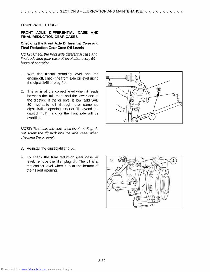
SECTION 3 – LUBRICATION AND MAINTENANCE
3-32
FRONT-WHEEL DRIVE
FRONT AXLE DIFFERENTIAL CASE AND FINAL REDUCTION GEAR CASES
Checking the Front Axle Differential Case and Final Reduction Gear Case Oil Levels
NOTE: Check the front axle differential case and final reduction gear case oil level after every 50 hours of operation.
1. With the tractor standing level and the
engine off, check the front axle oil level using the dipstick/filler plug ①.
2. The oil is at the correct level when it reads
between the 'full' mark and the lower end of the dipstick. If the oil level is low, add SAE 80 hydraulic oil through the combined dipstick/filler opening. Do not fill beyond the dipstick 'full' mark, or the front axle will be overfilled.
NOTE: To obtain the correct oil level reading, do not screw the dipstick into the axle case, when checking the oil level.
3. Reinstall the dipstick/filler plug. 4. To check the final reduction gear case oil
level, remove the filler plug ②. The oil is at the correct level when it is at the bottom of the fill port opening.
Downloaded from www.Manualslib.com manuals search engine

SECTION 3 – LUBRICATION AND MAINTENANCE
3-33
Changing the Front Axle Differential Case and
Final Reduction Gear Case Oil
NOTE: The front axle differential case and final reduction gear case oil should be changed after every 300 operating hours.
1. Place a suitable container beneath the oil plug. With the oil at normal operating temperature, drain the oil by removing the drain plug ① . After the oil has drained, reinstall the drain plug and discard the used oil.
2. Remove the dipstick/filler plug ② , on the
left-hand side of the axle housing. NOTE: To obtain correct oil level reading do not screw dipstick into axle housing when checking oil level.
Fill the axle with SAE 80 hydraulic oil until the oil level is between the full mark and the lower end of the dipstick. Reinstall the dipstick/filler plug.
NOTE: Approximate fluid capacity for the differential axle housing is 4 liters 3. Remove the drain plug ③, from each final
reduction gear case. After the oil has drained, reinstall each drain plug and discard the used oil. Remove the filler plug ④, from each final reduction gear case and fill with SAE 80 hydraulic oil so that the oil level is at the bottom of the fill port opening. Reinstall each filler plug.
NOTE: Approximate final reduction gear cases fluid capacity is 0.9 liters each. NOTE: To ensure correct steering operation, the stop bolt ⑤, should protrude a minimum of 32mm from the casing (standard FWD axle).
Downloaded from www.Manualslib.com manuals search engine

SECTION 3 – LUBRICATION AND MAINTENANCE
3-34
FRONT AXLE PIVOT FWD AXLE
NOTE: The center housing pivot points ① (front side) and ② (rear side) should be greased after every 50 hours of operation under normal conditions. Under extremely dirty conditions, lubrication should be carried out more frequently than every 50 hours. Use a good quality, multipurpose, lithium-base grease.
2
Downloaded from www.Manualslib.com manuals search engine

SECTION 3 – LUBRICATION AND MAINTENANCE
3-35
TRACTOR STORAGE
Below is a list of protective measures which should be taken if your tractor is to be stored for an extended period of time: 1. Thoroughly clean the tractor. Use touch-up
paint where necessary to prevent rust. 2. Check the tractor for worn or damaged parts.
Install new parts as required. 3. Raise the lift arms hydraulically to their fullest
raised position so that the lift piston is in a fully extended position. This fills the cylinder with oil and protects the cylinder wall surfaces from corrosion.
4. Lubricate the tractor. 5. Fill the fuel tank with No. 1 diesel fuel.
IMPORTANT: Do not use No. 2 diesel fuel for winter storage because of wax separation and setting at low temperature.
6. Open the drain valve of the radiator and
engine block. Flush the system, close the drain valves, and fill with a 50/50 solution of permanent antifreeze and clear water.
7. Remove the battery and clean it thoroughly.
Be sure that it is fully charged and that the electrolyte is at the proper level. Store the battery in a cool, dry place above freezing temperature, and charge it periodically during storage.
8. Place blocking under the tractor axles to remove the weight from the tires.
9. Cover the exhaust pipe opening. Tractors, which have been placed in storage, should be completely serviced in the following manner before using: 1. Inflate the tires to the recommended
pressures and remove the blocking. 2. Check the oil level in the engine crankcase,
power steering reservoir, the common sump (for the hydraulic lift, transmission, and rear axle), and the front-wheel drive axle.
3. Install a fully charged battery. 4. Check the cooling system for the proper level
(50/50 solution of permanent antifreeze and clear water).
5. Remove the exhaust pipe opening cover. 6. Start the engine and allow it to idle a few
minutes. Ensure the engine is receiving lubrication and that each control is functioning correctly.
7. Drive the tractor without a load and check to
make sure it is operating satisfactorily.
Downloaded from www.Manualslib.com manuals search engine

SECTION 3 – LUBRICATION AND MAINTENANCE
3-36
Downloaded from www.Manualslib.com manuals search engine

SECTION 3 – LUBRICATION AND MAINTENANCE
3-37
Downloaded from www.Manualslib.com manuals search engine

SECTION 3 – LUBRICATION AND MAINTENANCE
3-38
METRIC BOLT TORQUE SPECIFICATION
Bolt Size Grade No.
Coarse Thread Fine Thread
Pitch (mm) Pounds-Feet Newton Meters Pitch (mm) Pounds-Feet Newton-Meters
M6
4T
1.0
3.6 – 5.1 4.9 – 6.9
– – – 7T 6.1 – 8.3 8.3 – 11.3
10T 8.7 – 11.6 11.8 – 15.7
M8
4T
1.25
9.4 – 12.3 12.7 – 16.7
1.0
11.2 – 14.8 15.2 – 20.1
7T 16.6 – 21.0 22.6 – 28.4 19.5 – 25.3 26.5 – 34.3
10T 21.0 – 26.8 28.4 – 36.3 22.4 – 29.7 30.4 – 40.2
M10
4T
1.5
18.8 – 24.6 25.5 – 33.3
1.25
21.0 – 26.8 28.4 – 36.3
7T 32.5 – 41.2 44.1 – 55.9 36.2 – 46.3 49.0 – 62.8
10T 39.8 – 51.4 53.9 – 69.6 42.7 – 54.2 57.9 – 73.5
M12
4T
1.75
27.5 – 34.7 37.3 – 47.1
1.25
31.8 – 40.5 43.1 – 54.9
7T 48.5 – 61.5 65.7 – 83.4 55.0 – 69.4 74.5 – 94.1
10T 68.0 – 85.4 92.2 – 116 73.1 – 93.3 99.0 – 127
M14
4T
2.0
46.3 – 59.3 62.8 – 80.4
1.5
51.4 – 64.4 69.6 – 87.3
7T 76.7 – 96.9 104 – 131 86.1 – 109 117 – 148
11T 102 – 129 139 – 175 108 – 137 147 – 186
M16
4T
2.0
63.6 – 81.0 86.3 – 110
1.5
67.3 – 84.6 91.2 – 115
7T 110 – 136 149 – 184 116 – 142 157 – 192
11T 152 – 188 206 – 255 163 – 199 221 – 270
M18
4T
2.0
83.9 – 104 114 – 141
1.5
96.9 – 120 131 – 163
7T 145 – 174 196 – 235 170 – 206 230 – 279
11T 203 – 246 275 – 333 221 – 271 299 – 368
M20
4T
2.5
106 – 132 144 – 179
1.5
127 – 156 172 – 211
7T 177 – 213 240 – 289 203 – 246 275 – 333
11T 268 – 325 363 – 441 293 – 358 397 – 485
Downloaded from www.Manualslib.com manuals search engine

4-1
SECTION 4 SPECIFICATIONS
Model ST460 SSS (Synchro Shuttle Shift)
Model ST460 EHSS (Electro Hydro Shuttle Shift)
ENGINE
Type N844LT Diesel N844LT Diesel
Engine Gross Horsepower 44.7 kw (60hp) 44.7 kw (60hp)
Cylinders 4 4
Bore 75 mm (2.95") 84 mm 84 mm
Stroke 100 mm 100 mm
Displacement 2.216 L with Turbo 2.216 L with Turbo
Compression Ratio 23.5: 1 23.5: 1
Firing Order 1 – 3 – 4 – 2 1 – 3 – 4 – 2
Low Idle Speed 1000 ± 50 RPM 1000 ± 50 RPM
Maximum Speed
High Idle 3000 ± 50 RPM 3000 ± 50 RPM
Rated 2800 ± 50 RPM 2800 ± 50 RPM
Valve Clearance (Cold):
Intake 0.20 mm 0.20 mm
Exhaust 0.20 mm 0.20 mm
CAPACITIES
Fuel Tank 54 liters 54 liters
Cooling System 5.5 liters 5.5 liters
Engine Crankcase
With Filter 7.0 liters 7.0 liters
Rear Axle & Transmission 38.0 liters 46.0 liters
Power Steering 1.8 liters 1.8 liters
Front Axle Differential/Final Reduction Gear Case
5.8 liters 5.8 liters
Downloaded from www.Manualslib.com manuals search engine

SECTION 4 – SPECIFICATIONS
4-2
Model ST460 SSS (Synchro Shuttle Shift)
Model ST460 EHSS (Electro Hydro Shuttle Shift)
COOLING SYSTEM
Type Pressurized Liquid with Recirculating Bypass
Pressurized Liquid with Recirculating Bypass
Water Pump:
Type Centrifugal Centrifugal
Drive V – Belt V – Belt
Belt Deflection 10 – 15 mm when 9 – 11 kg thumb pressure is applied midway between pulleys
10 – 15 mm when 9 – 11 kg thumb pressure is applied midway between pulleys
Fan Diameter 410 mm 410 mm
Number of Fan Blades 8 8
Thermostat:
Start to Open 71ºC 71ºC
Fully Open 82ºC 82ºC
Radiator Cap 110 kPa 110 kPa
Antifreeze Ethylene glycol Ethylene glycol
ELECTRICAL SYSTEM
Main system Protection 40A Slow – Blow fuse 40A Slow – Blow fuse
Number of fuses for Circuit Protection
5
5
Alternator 12V / Heavy Duty / 55A 12V / Heavy Duty / 55A
Battery Type 12V, 64 amp. 105D31R 12V, 64 amp. 105D31R
Start HP (kw) Rating 2.7 (2.0) 2.7 (2.0)
Starting Motor Pre-Engaged Reduction Pre-Engaged Reduction
FUEL SYSTEM
Fuel Type
Type of Fuel to Use if Above 4.5ºC
No.2-Diesel, Cetane Rating: Minimum 40
No.2-Diesel, Cetane Rating: Minimum 40
Type of Fuel to Use if Below 4.5ºC
No.1-Diesel, Cetane Rating: Minimum 40
No.1-Diesel, Cetane Rating: Minimum 40
Injection Pump
Type In-Line In-Line
Timing 18º – 20º BTDC 18º – 20º BTDC
Downloaded from www.Manualslib.com manuals search engine

SECTION 4 – SPECIFICATIONS
4-3
Model ST460 SSS (Synchro Shuttle Shift)
Model ST460 EHSS (Electro Hydro Shuttle Shift)
BRAKES
Type Wet Disc Wet Disc
4 Discs per Side 175 mm × 143 mm Diameter 175 mm × 143 mm Diameter
STEERING
Type Power Power
Pump Flow @ Rated RPM 20.8 liters/min 20.8 liters/min
Steering Relief Valve Setting 14.2 MPa 14.2 MPa
Turns, Lock-to-Lock:
FWD 3.7 / 2.9 3.7 / 2.9
Front Wheel Toe-In 0 – 5 mm 0 – 5 mm
Turning Radius w/o Brakes:
FWD 3150 mm 3150 mm
Max Turn Angle: FWD 56º 56º
Front to Rear Axle Ratio 1.5968 1.5968
POWER TAKE-OFF (PTO)
Type Independent (PTO mode ①) Transmission (PTO mode ②)
Independent (PTO mode ①) Transmission (PTO mode ②)
Shaft:
Rear PTO 35 mm 35 mm
Mid PTO N/A N/A
Engine Speed for 540 RPM Rear PTO Operation
2475 RPM (PTO Speed ①) 1755 RPM (PTO Speed ②)
2475 RPM (PTO Speed ①) 1755 RPM (PTO Speed ②)
Horsepower PTO Observed 38.0 kw (51 hp) 38.0 kw (51 hp)
HYDRAULIC LIFT SECTION
Type Open Center Open Center
Pump Type Gear Gear
Pump Capacity 43.9 L/min 43.9 L/min
System Relief Valve Setting 17.2 MPa 17.2 MPa
Number of Remotes Available 3 (Optional) 3 (Optional)
Downloaded from www.Manualslib.com manuals search engine

SECTION 4 – SPECIFICATIONS
4-4
ST460 SSS TRANS MISSION SPEEDS: KPH (AT 2800 ENGINE RATED RPM)
F O R W A R D
Speed Creep Range Main Small AG 13.6 - 28
Lage AG 14.9 - 28
Turf 475/65D20
Metric AG 380/70R28
1 C L 1 0.17 0.17 0.14 0.16
2 2 0.22 0.24 0.19 0.22
3 3 0.29 0.31 0.25 0.29
4 4 0.38 0.40 0.32 0.38
5 M 1 0.43 0.45 0.36 0.43
6 2 0.58 0.61 0.49 0.58
7 3 0.76 0.80 0.64 0.76
8 4 0.98 1.03 0.83 0.97
9 H 1 1.18 1.24 0.99 1.17
10 2 1.59 1.68 1.34 1.58
11 3 2.08 2.19 1.76 2.07
12 4 2.68 2.82 2.62 2.66
13 H L 1 1.75 1.85 1.48 1.74
14 2 2.37 2.50 2.00 2.36
15 3 3.11 3.27 2.62 3.09
16 4 3.99 4.20 3.36 3.96
17 M 1 4.54 4.78 3.83 4.51
18 2 6.15 6.47 5.19 6.11
19 3 8.08 8.48 6.79 8.00
20 4 10.33 10.88 8.71 10.27
21 H 1 12.42 13.08 10.48 12.34
22 2 16.82 17.71 14.19 16.71
23 3 22.02 23.18 18.57 21.88
24 4 28.26 31.87 23.83 28.08
R E V E R S E
1 C L 1 0.18 0.19 0.15 0.18
2 2 0.24 0.25 0.20 0.24
3 3 0.32 0.33 0.27 0.31
4 4 0.41 0.43 0.34 0.40
5 M 1 0.46 0.49 0.39 0.46
6 2 0.63 0.66 0.53 0.62
7 3 0.82 0.86 0.69 0.81
8 4 1.05 1.11 0.89 1.05
9 H 1 1.27 1.33 1.07 1.26
10 2 1.71 1.80 1.45 1.70
11 3 2.24 2.36 1.89 2.23
12 4 2.88 3.03 2.43 2.86
13 H L 1 1.89 1.99 1.59 1.87
14 2 2.55 2.69 2.15 2.54
15 3 3.34 3.52 2.82 3.32
16 4 4.29 4.52 3.62 4.26
17 M 1 4.89 5.14 4.12 4.85
18 2 6.62 6.97 5.58 6.57
19 3 8.66 9.12 7.31 8.61
20 4 11.12 11.70 9.38 11.04
21 H 1 13.36 14.07 11.27 13.28
22 2 18.10 19.05 15.26 17.98
23 3 23.69 24.94 19.98 23.54
24 4 30.40 32.01 25.64 30.21
Downloaded from www.Manualslib.com manuals search engine

SECTION 4 – SPECIFICATIONS
4-5
ST460 EHSS TRANS MISSION SPEEDS: KPH (AT 2800 ENGINE RATED RPM)
F O R W A R D
Speed Creep Range Main Small AG 13.6 - 28
Lage AG 14.9 - 28
Turf 475/65D20
Metric AG 380/70R28
1 C L 1 0.18 0.19 0.15 0.18
2 2 0.24 0.25 0.20 0.24
3 3 0.31 0.33 0.25 0.31
4 4 0.40 0.42 0.34 0.40
5 M 1 0.46 0.48 0.39 0.45
6 2 0.62 0.65 0.52 0.61
7 3 0.81 0.85 0.68 0.80
8 4 1.04 1.09 0.88 1.03
9 H 1 1.25 1.31 1.05 1.24
10 2 1.69 1.78 1.43 1.68
11 3 2.21 2.33 1.87 2.20
12 4 2.84 2.99 2.40 2.82
13 H L 1 1.86 1.96 1.57 1.85
14 2 2.52 2.65 2.13 2.51
15 3 3.30 3.47 2.78 3.28
16 4 4.24 4.46 3.57 4.21
17 M 1 4.82 5.08 4.07 4.79
18 2 6.53 6.87 5.51 6.49
19 3 8.55 9.00 7.21 8.49
20 4 10.97 11.55 9.25 10.90
21 H 1 13.19 13.88 11.12 13.10
22 2 17.86 18.80 15.06 17.74
23 3 23.38 24.61 19.72 23.23
24 4 30.00 31.58 25.31 29.81
R E V E R S E
1 C L 1 0.18 0.19 0.15 0.18
2 2 0.24 0.25 0.20 0.24
3 3 0.32 0.33 0.27 0.31
4 4 0.41 0.43 0.34 0.40
5 M 1 0.46 0.49 0.39 0.46
6 2 0.63 0.66 0.53 0.62
7 3 0.82 0.86 0.69 0.81
8 4 1.05 1.11 0.89 1.05
9 H 1 1.27 1.33 1.07 1.26
10 2 1.71 1.80 1.45 1.70
11 3 2.24 2.36 1.89 2.23
12 4 2.88 3.03 2.43 2.86
13 H L 1 1.89 1.99 1.59 1.87
14 2 2.55 2.69 2.15 2.54
15 3 3.34 3.52 2.82 3.32
16 4 4.29 4.52 3.62 4.26
17 M 1 4.89 5.14 4.12 4.85
18 2 6.62 6.97 5.58 6.57
19 3 8.66 9.12 7.31 8.61
20 4 11.12 11.70 9.38 11.04
21 H 1 13.36 14.07 11.27 13.28
22 2 18.10 19.05 15.26 17.98
23 3 23.69 24.94 19.98 23.54
24 4 30.40 32.01 25.64 30.21
Downloaded from www.Manualslib.com manuals search engine

SECTION 4 – SPECIFICATIONS
4-6
Model ST460 SSS
(Synchro Shuttle Shift) Model ST460 EHSS (Electro Hydro Shuttle Shift)
CAST IRON WEIGHTS
Front End: (2) weights @ 30 kg each or (5) weights @ 30 kg with optional weights bracket
(2) weights @ 30 kg each or (5) weights @ 30 kg with optional weights bracket
Rear Wheel (per wheel) (4) weights @ 30 kg each (4) weights @ 30 kg each
DRAWBARS
Extension / Clevis Standard Standard
3-POINT HITCH
Category Type I and II I and II
Position Control Type Mechanical Mechanical
Draft Control Type Top Link Sensing Top Link Sensing
Drop Rate Control Standard Standard
Lift Capacity @ 24"
Behind kg. 1570 kg 1570 kg
TIRES
FRONT:
Small AG: 8 - 16 8 - 16
Large AG: 9.5 - 16 9.5 - 16
Turf 27 x 10.50 - 15 27 x 10.50 - 15
Metric AG: 260/70R16 260/70R16
REAR:
Small AG: 13.6 - 28 13.6 - 28
Large AG: 14.9 - 28 14.9 - 28
Turf 475/65D20 475/65D20
Metric AG: 380/70R28 380/70R28
WHEEL BOLT TORQUES
Front Wheel-Disc-to-Hub:
FWD 175 N·m 175 N·m
Rear Wheel-
Disc-to-Axle 175 N·m 175 N·m
Disc-to-Rim 230 N·m 230 N·m
ROPS ATTACHING BOLT TORQUES
ROPS to Rear Axle 108 N·m 108 N·m
ROPS to Lower and Center Frame
74 N·m 74 N·m
Downloaded from www.Manualslib.com manuals search engine

SECTION 4 – SPECIFICATIONS
4-7
Downloaded from www.Manualslib.com manuals search engine

SECTION 4 – SPECIFICATIONS
4-8
GENERAL DIMENSIONS
Model ST460 SSS (Synchro Shuttle Shift)
Model ST460 EHSS (Electro Hydro Shuttle Shift)
① – LENGTH, Overall:
STD 4WD (Less 3-pt hitch and tires, to end of drawbar)
3225 mm 3225 mm
STD 4WD (With 3-pt hitch in Horizontal position)
3601 mm 3601 mm
② – WHEEL BASE:
FWD 1900 mm 1900 mm
HEIGHTS
③ – Top of Steering Wheel:
Small Ag. Tires Variable Variable
Large Ag. Tires Variable Variable
Turf Tires Variable Variable
Metric Ag. Tires Variable Variable
④ – Top of ROPS – FOLDING
Small Ag. Tires - UP 2552 mm 2552 mm
Small Ag. Tires - Down 1911 mm 1911 mm
Large Ag. Tires - UP 2585 mm 2585 mm
Large Ag. Tires - Down 1944 mm 1944 mm
Turf Tires - UP 2454 mm 2454 mm
Turf Tires - Down 1813 mm 1813 mm
Metric Ag. Tires 2548 mm 2548 mm
Metric Ag. Tires 1907 mm 1907 mm
⑤ – Hood Height (Top of Instrument cluster)
Small Ag. Tires 1495 mm 1495 mm
Large Ag. Tires 1526 mm 1526 mm
Turf Tires 1425 mm 1425 mm
Metric Ag. Tires 1492 mm 1492 mm
⑥ – WIDTH (Rear Tires – Outside to Outside)
Small Ag. Tires 1575 to 2277 mm 1575 to 2277 mm
Large Ag. Tires 1718 to 2322 mm 1718 to 2322 mm
Turf Tires 1846 mm 1846 mm
Metric Ag. Tires 1727 to 2331 mm 1727 to 2331 mm
⑦ – MINIMUM GROUND CLEARANCE (Under FWD Axle)
Small Ag. Tires 322 mm 322 mm
Large Ag. Tires 354 mm 354 mm
Turf Tires 273 mm 273 mm
Metric Ag. Tires 319 mm 319 mm
Downloaded from www.Manualslib.com manuals search engine
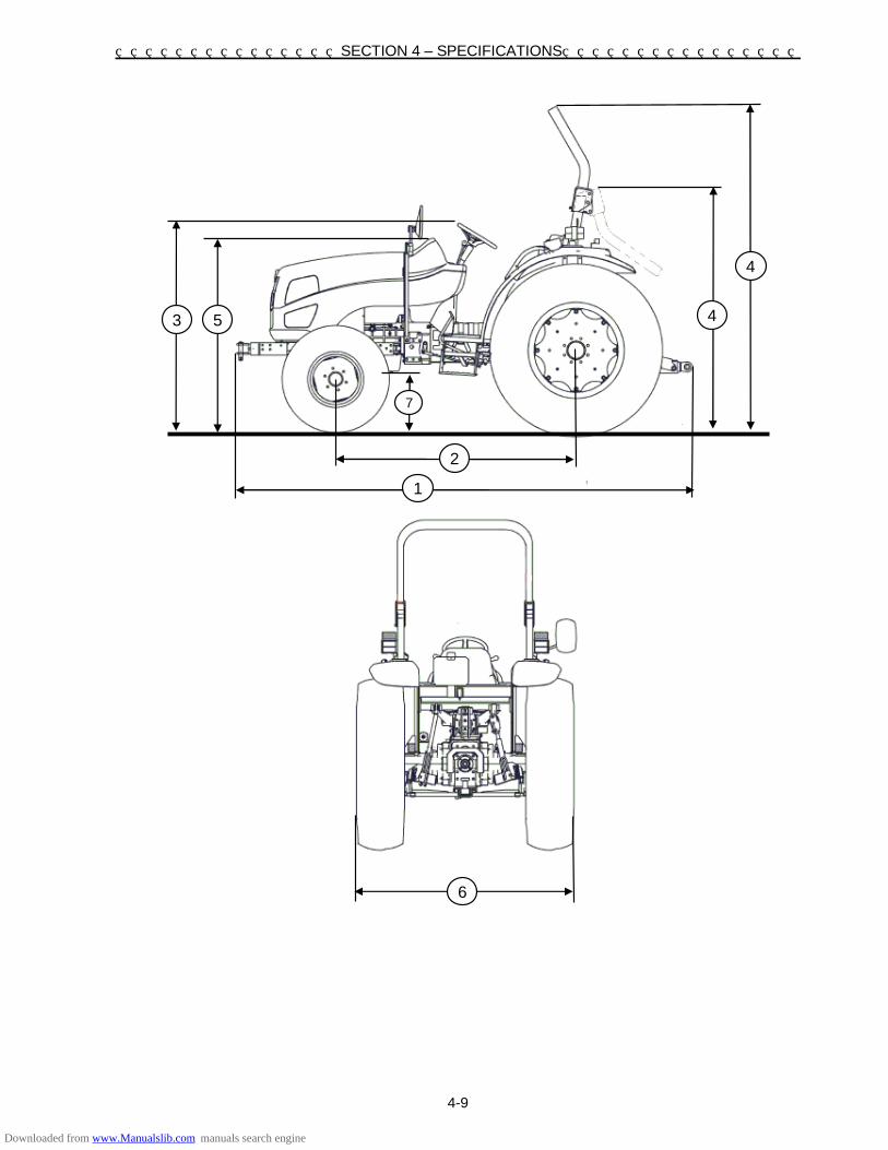
SECTION 4 – SPECIFICATIONS
4-9
3 5 4
4
7
1
2
6
Downloaded from www.Manualslib.com manuals search engine

SECTION 4 – SPECIFICATIONS
4-10
Model ST460 SSS (Synchro Shuttle Shift)
Model ST460 EHSS (Electro Hydro Shuttle Shift)
WEIGHT (With ROPS)
Small Ag. Tires 1845 kg 1860 kg
Large Ag. Tires 1905 kg 1920 kg
Turf Tires 1820 kg 1835 kg
Metric Ag. Tires 1905 kg 1920 kg WHEEL TREAD SETTINGS
NOTE: Tread settings are measured from center of tire to center of tire. Front Wheel Settings
Tire Type Setting Note
(AG) 8 - 16 1335 mm Not Adjustable
(AG) 9.5 - 16 1442 mm Not Adjustable
(TURF) 27 x 10.5 - 15 1462 mm Not Adjustable
(AG) 260/70R16 1442 mm Not Adjustable
IMPORTANT: Never attempt to widen the tread setting by reversing the front wheels on a front-wheel drive system. NOTE: Torque front wheel bolts to 175 N ·m. Rear Wheel Settings
Tire Type MIN (DISH IN) MAX (DISH OUT) NO. OF POSITION
(AG) 13.6 - 28 1240 mm 1942 mm 8
(AG) 14.9 - 28 1338 mm 1942 mm 7
(TURF) 475/65D20 N/A 1382 mm 1
(AG) 380/70R28 1338 mm 1942 mm 7
NOTE: Torque rear wheel bolts to 175 N·m. Torque rim to disc bolts to 230 N·m
Downloaded from www.Manualslib.com manuals search engine

SECTION 4 – SPECIFICATIONS
4-11
Position Rear FWD Tire Dimensions, mm Tire Type Inside To Inside Tread Setting Outside To Outside
A 905 1240 1575
(AG) 13.6 - 28
B 1003 1338 1673 C 1109 1444 1779 D 1207 1542 1877 E 1305 1640 1975 F 1403 1738 2073 G 1509 1844 2179 H 1607 1942 2277
A N/A N/A N/A
(AG) 14.9 - 28
B 958 1338 1718 C 1064 1444 1824 D 1162 1542 1922 E 1260 1640 2020 F 1358 1738 2118 G 1464 1844 2244 H 1562 1942 2322
A N/A N/A N/A
(AG) 380/70R28
B 949 1338 1727 C 1055 1444 1833 D 1153 1542 1931 E 2029 1640 2029 F 2127 1738 2127 G 1455 1844 2233 H 1553 1942 2331
918 1382 1846 (TURF) 475/65D20
Downloaded from www.Manualslib.com manuals search engine

SECTION 4 – SPECIFICATIONS
4-12
INDEX Airborne Noise Emission ······························ 1-22 Air Cleaner ··················································· 3-11 Alternator ······················································ 3-22 Battery ·························································· 3-21 Brake Adjustment ········································· 3-29 Brake Controls ·············································· 2-14 Brake Lights ················································· 2-12 Brake Pedal Lock ········································· 2-14 Break-in Procedures ······································· 2-8 Cast Iron Weights (Optional) ························ 2-40 Cleaning the Tractor ····································· 1-2 Clutch Pedal (SSS)······································· 2-19 Clutch Pedal Adjustment (SSS) ···················· 3-30 Clutch/Inching Pedal Maximum
Travel Adjustment ····································· 3-30 Contents ························································· 0-2 Controls and Instruments and Operation ········ 2-1 Cooling System ············································ 3-17 Creep Lever (Creep, High) ·························· 2-18 Decal Placement Guide ································ 1-12 Deluxe Three-Point Linkage ························· 2-26 Diesel Fuel ············································ 1-10, 3-3 Differential Control ········································ 2-20 Draft Control ················································· 2-29 Draft Control Adjustment ······························ 2-32 Draft Control Operation ································ 2-30 Drink Holder ················································· 2-27 Driving the Tractor ································· 1-5, 2-36 Ecology and the Environment ······················· 1-11 Electrical Socket for Trailer ··························· 2-12 Electro-magnetic interference (EMC) ·············· 1-2 EHSS or SSS Shift 24x24 Transmission ······· 2-16 Engine ···························································· 3-6 Extension/Clevis Drawbar····························· 2-24 Flasher Turn Lights (Turn Signals) ·············· 2-11 Flasher Warning (Hazard) Lights ·················· 2-11 Front Axle Differential Case and Final
Reduction Gear Case ····························· 3-32 Front Axle Pivot Fwd Axle ····························· 3-34 Front-Wheel Drive ································ 2-15,3-32 Front-Wheel Toe-In ······································ 3-28 Fuel and Lubricant Service Procedures ·········· 3-6 Fuel Filter ······················································· 3-8 Fuel Shutoff Valve ········································ 2-13 Fuse Block ··················································· 3-23 General Dimensions ······································· 4-8 General Information ································· 1-1, 3-1 General Maintenance ··································· 3-17 Hazards Related to Vibration Exposure ········ 1-22 Headlamp ····················································· 3-24 Hood Latch ··················································· 2-25
Horn ····························································· 2-12 HPL Drop Rate Control Valve ······················· 2-33 Hydraulic Lift Rocker ····································· 2-33 Hydraulic Manifold Block/Diverter Valve ······· 2-34 Hydraulic Power Lift (H.P.L.)(3 PT) ··············· 2-28 Hydraulics System Oil Filter ·························· 3-14 Improvements ················································· 0-1 Inching Pedal (EHSS) ································· 2-19 Inching Pedal Adjustment (EHSS) ·············· 3-31 Index ···························································· 4-12 Instruction Decals ········································· 1-18 Instrument Lights ·········································· 3-25 Instrument Panel ············································ 2-4 Key Switch ······················································ 2-6 Light Switches ·············································· 2-10 Lighting ··························································· 2-9 Liquid Ballast (Optional) ································ 2-41 Lubricants ······················································· 3-5 Lubrication and Maintenance ·························· 3-1 Lubrication and Maintenance Chart ················ 3-2 Lubrication Fittings·········································· 3-3 Main Fuse ····················································· 3-23 Maintenance and Inspection of the Rollover
Protective Structure (POPS) ··················· 3-20 Machine Safety ··············································· 1-4 Metric Bolt Torque Specification ············· 1-3,3-38 Notes ···························································· 4-19 Operating in Both Position and Draft Control ··············································· 2-30 Operating the Tractor ······································ 1-6 Operating the Power Take Off ························ 1-7 Parking Brake Adjustment ···························· 3-29 Parking Brake Control ··································· 2-14 Personal Safety ·············································· 1-4 Position Control ············································ 2-28 Position Control Adjustment ·························· 2-31 Possible Damage to the ROPS ····················· 3-20 Power Steering ············································· 3-16 Power Take Off (PTO) ································ 2-21 Power Take Off (PTO) Operation ·················· 2-23 Pre-delivery Service ······························ 4-15,4-17 Pre-heating the System ·································· 2-6 Precautionary Statements ······························ 1-4 Prevention of Fire or Explosion ······················· 1-9 PTO Control Switch ······································ 2-21 PTO Mode Select Switch ······························ 2-21 PTO Operation (Without Operator in Seat) ···························· 2-23 PTO Shield and Cap ····································· 2-22 PTO Speed Shift Lever ································· 2-22 Rear Remote Control Valve (Optional)·········· 2-35
Downloaded from www.Manualslib.com manuals search engine

SECTION 4 – SPECIFICATIONS
4-13
Rim to Disc Bolt Torque ······························· 3-27 Rollover Protective Structure (ROPS) ··· 1-10, 2-2 Safety Precautions ········································· 1-5 Safety Decals ··············································· 1-12 Safety Frame (ROPS) ·································· 1-10 Seat and Mirror ·············································· 2-1 Service Parts ·················································· 1-2 Servicing the Tractor ······································ 1-7 Specification ··················································· 4-1 Starting the Engine ········································· 2-7 Starting the Tractor with Jumper Cables ········ 2-8 Steering Wheel ·············································· 2-2 Stopping the Engine ······································· 2-8 Switching Between Single and
Double Acting ··········································· 2-35 Taillight/Flasher Warning Light/Side Light ···· 3-24 The Tractor ···················································· 1-5 Throttle Controls ·········································· 2-13 Tire Pressure ··············································· 2-41 Tires ····························································· 3-26 To the owner ·················································· 0-1 Tool Box ······················································· 2-27 Top Link Main Spring Adjustment ················· 2-32 Towing the Tractor ······································· 2-24 Tractor Hydraulics ········································ 2-28 Tractor Storage ············································ 3-35 Tractor Weighting ········································· 2-39 Transmission Main Shift Lever (1st, 2nd, 3rd, 4th) ···································· 2-18 Transmission Range Lever (Low, Medium, High) ································· 2-18 Transmission Shuttle Lever (Forward or Reverse) EHSS ······················· 2-17 Transmission Shuttle Lever (Forward or Reverse) SSS ························· 2-17 Transmission, Rear Axle,
and Hydraulic System ···························· 3-14 Transport the Tractor ····································· 1-9 Two Lever Controls Position
Control Operation ····································· 2-30 Under No Circumstances: ···························· 1-10 Universal Symbols ······································· 1-21 Weighting for Stability ·································· 2-39 Weighting Limitations ··································· 2-39 Wheel Bolt Torque ······································· 3-27 Wheel Tread Settings ··························· 2-37,4-10
Downloaded from www.Manualslib.com manuals search engine

SECTION 4 – SPECIFICATIONS
4-14
Downloaded from www.Manualslib.com manuals search engine

SECTION 4 – SPECIFICATIONS
4-15
OWNER COPY
PRE-DELIVERY SERVICE CHECK AND ADJUST AS REQUIRED
Tractor ST460
INOPERATIVE SERVICE CHECKS 1. _____ Tire Pressure – 2-41
2. _____ Air Cleaner Element & Hose Connections – 3-11 ~ 3-13
3. _____ Radiator Coolant Level – 3-17, 3-18
4. _____ Fan Belt Tension – 3-19
5. _____ Battery Cleanliness, Vent Openings, Electrolyte Level, & Charge – 3-21
6. _____ Power Steering Reservoir Oil Level – 3-16
7. _____ Engine Oil Level – 3-6
8. _____ Transmission & Rear Axle Oil Level – 3-14
9. _____ Front Axle & Final Reduction Gear Case Oil Level (FWD) – 3-32
10. ____ Hydraulic Lift Control Drop Rate Adjustment – 2-33
11. ____ Top Link (present) – 2-26
12. ____ Brake Adjustment & Pedal Equalization – 3-29
13. ____ Rear Wheel Bolt Torque – 175 N·m - 3-27
14. ____ Front Wheel Bolt Torque – 175 N·m - 3-27
15. ____ Front Wheel Toe-in – 3-28
16. ____ Fuel Level – 3-4
17. ____ Seat Functions – 2-1
SAFETY ITEMS CHECKS
1. _____ ROPS Installed – 2-2
2. _____ Seat Belts Installed – 2-1
3. _____ ROPS Bolt Torque – 74.5 N·m/108 N·m
– 3-20
4. _____ PTO Shield Installed – 2-22
5. _____ Safety Decals and Instruction
Decals Installed – 1-12 ~ 1-20
6. _____ Neutral Start Switches Operation – 2-7,
7. _____ Parking Brake & Operation – 2-14
8. _____ Flashing Lights/Tail Lights/Brake Lights Operation – 2-11, 2-12
9. _____ Operator's Manual #300813390
10. ____ Horn Operation – 2-12
OPERATIVE SERVICE CHECKS
All operating checks are to be performed with tractor at normal operating temperature.
1. _____ Lights & Instruments for Proper Operation, & Fuel Shut Down with Key Switch OFF – 2-7, 2-10
2. _____ Fluid & Oil Leaks
3. _____ Maximum No-load Speed & Idle Speed Adjustments – 4-1
4. _____ PTO Engagement & Disengagement PTO Lever and Switches. – 2-21, 2-22
5. Hydraulic System:
_____ Selector Lever for Position Control – 2-28
_____ Drop Rate Operation – 2-33
6. _____ FWD-Drive Lever Operation – 2-15
TRACTOR MODEL NO. ________________ INSPECTION PERFORMED _____________________
TRACTOR MODEL NO. ________________ WARRANTY EXPLAINED ______________________
Owner's Signature _________________________________________ Date ___________________
Owner's Signature _________________________________________ Date ___________________
Downloaded from www.Manualslib.com manuals search engine

SECTION 4 – SPECIFICATIONS
4-16
Downloaded from www.Manualslib.com manuals search engine

SECTION 4 – SPECIFICATIONS
4-17
DEALER COPY
PRE-DELIVERY SERVICE CHECK AND ADJUST AS REQUIRED
Tractor ST460
INOPERATIVE SERVICE CHECKS 1. _____ Tire Pressure – 2-41
2. _____ Air Cleaner Element & Hose Connections – 3-11 ~ 3-13
3. _____ Radiator Coolant Level – 3-17, 3-18
4. _____ Fan Belt Tension – 3-19
5. _____ Battery Cleanliness, Vent Openings, Electrolyte Level, & Charge – 3-21
6. _____ Power Steering Reservoir Oil Level – 3-16
7. _____ Engine Oil Level – 3-6
8. _____ Transmission & Rear Axle Oil Level – 3-14
9. _____ Front Axle & Final Reduction Gear Case Oil Level (FWD) – 3-32
10. ____ Hydraulic Lift Control Drop Rate Adjustment – 2-33
11. ____ Top Link (present) – 2-26
12. ____ Brake Adjustment & Pedal Equalization – 3-29
13. ____ Rear Wheel Bolt Torque – 175 N·m - 3-27
14. ____ Front Wheel Bolt Torque – 175 N·m - 3-27
15. ____ Front Wheel Toe-in – 3-28
16. ____ Fuel Level – 3-4
17. ____ Seat Functions – 2-1
SAFETY ITEMS CHECKS
1. _____ ROPS Installed – 2-2
2. _____ Seat Belts Installed – 2-1
3. _____ ROPS Bolt Torque – 74.5 N·m/108 N·m
– 3-20
4. _____ PTO Shield Installed – 2-22
5. _____ Safety Decals and Instruction
Decals Installed – 1-12 ~ 1-20
6. _____ Neutral Start Switches Operation – 2-7,
7. _____ Parking Brake & Operation – 2-14
8. _____ Flashing Lights/Tail Lights/Brake Lights Operation – 2-11, 2-12
9. _____ Operator's Manual #300813390
10. ____ Horn Operation – 2-12
OPERATIVE SERVICE CHECKS
All operating checks are to be performed with tractor at normal operating temperature.
1. _____ Lights & Instruments for Proper Operation, & Fuel Shut Down with Key Switch OFF – 2-7, 2-10
2. _____ Fluid & Oil Leaks
3. _____ Maximum No-load Speed & Idle Speed Adjustments – 4-1
4. _____ PTO Engagement & Disengagement PTO Lever and Switches. – 2-21, 2-22
5. Hydraulic System:
_____ Selector Lever for Position Control – 2-28
_____ Drop Rate Operation – 2-33
6. _____ FWD-Drive Lever Operation – 2-15
TRACTOR MODEL NO. ________________ INSPECTION PERFORMED _____________________
TRACTOR MODEL NO. ________________ WARRANTY EXPLAINED ______________________
Owner's Signature _________________________________________ Date ___________________
Owner's Signature _________________________________________ Date ___________________
Downloaded from www.Manualslib.com manuals search engine

SECTION 4 – SPECIFICATIONS
4-18
Downloaded from www.Manualslib.com manuals search engine

SECTION 4 – SPECIFICATIONS
4-19
NOTES
Downloaded from www.Manualslib.com manuals search engine

SECTION 4 – SPECIFICATIONS
4-20
Downloaded from www.Manualslib.com manuals search engine

Printed in Japan
ST460, 300813390 110301-001 R
HEAD OFFICE BYGS Shinjuku Bldg,
2-19-1, Shinjuku, Shinjuku-ku, Tokyo 160-0022, Japan
URL: http://www.ihi-shibaura.com
Downloaded from www.Manualslib.com manuals search engine