manuel logiciel pompe lowra
TRANSCRIPT

User Manual
Pump Selection Programme

Contents
3
CONTENTS
About This User Manual................................................................................................5 Copyright......................................................................................................................5 Trademarks ..................................................................................................................5 Conditions Of Use.......................................................................................................6
Introduction......................................................................................................................7 The Selection Programme.........................................................................................7 Interfaces......................................................................................................................8 System Requirements ................................................................................................9 Installation ....................................................................................................................9
Start Menu..................................................................................................................... 11 Settings and Data Transfer......................................................................................... 11
Menu File................................................................................................................... 11 Menu Edit .................................................................................................................. 14 Menu Settings........................................................................................................... 18 Menu Extras.............................................................................................................. 26
Hydraulic Selection...................................................................................................... 28 Index Card Operating Data..................................................................................... 29 Index Card Fluid....................................................................................................... 31 Index Card Search Options .................................................................................... 32 Select......................................................................................................................... 32
Pump Selection Browser............................................................................................. 33 Pump Selection Dialogue........................................................................................... 34
Filtering and Sorting the Pump List...................................................................... 35 Energy Costs / Running Costs.............................................................................. 36 Ratings of Fluids....................................................................................................... 37 Current Configuration.............................................................................................. 38 Motor .......................................................................................................................... 39 Coupling..................................................................................................................... 40 Base Plate................................................................................................................. 40 Index Card Diagram................................................................................................. 41 Index Card Product Description............................................................................. 47 Index Card Dimensions........................................................................................... 48 Index Card Materials ............................................................................................... 49 Index Card Shaft Seal............................................................................................. 51 Index Card Print Preview/Print............................................................................... 52 User-defined Pages ................................................................................................. 53
Accessory Selection.................................................................................................... 53 Spare parts selection................................................................................................... 56
Contents
4
Project Management................................................................................................... 58 Buttons - Functions .................................................................................................. 60 Index Card Prices..................................................................................................... 65 Index Card Data Sheet............................................................................................ 68
Create and Edit Data Sheets ..................................................................................... 72 Menu File................................................................................................................... 72 Menu Edit .................................................................................................................. 74 Menu View................................................................................................................. 76 Menu Tools ............................................................................................................... 77 Left Toolbar............................................................................................................... 80 Import Test Data....................................................................................................... 82 Toolbar Pump Data.................................................................................................. 82 Toolbar Operating Data........................................................................................... 93 Toolbar Project Data................................................................................................ 96 Toolbar Graphic........................................................................................................ 99
Compare Pumps ........................................................................................................102 Index.............................................................................................................................103
About This User Manual
5
ABOUT THIS USER MANUAL The software described in this manual is placed at your disposal according to the conditions of a license agreement and may only be used in compliance with the following conditions.
COPYRIGHT
Publisher: VSX – VOGEL SOFTWARE GMBH This user manual as well as the software programmes are subject to international copyright laws. Any duplication will be prosecuted. Warranty limitations: Although this manual was drawn up with utmost care, we are not liable for the correctness of the contents. The same applies to all names and data used in the presented examples. The information in this manual is subject to alterations without prior notice. We are grateful for any suggestions regarding improvements as well as for any points that may be brought to our attention as well as constructive criticism. © Copyright VSX – VOGEL SOFTWARE GMBH, 1999 – 2002. All rights reserved.
TRADEMARKS
This documentation contains references to protected trademarks that are not explicitly identified within the text. Despite the fact, that protected trademarks are not explicitly identified, the rights of VSX or third parties are protected.
About This User Manual
6
CONDITIONS OF USE
The use of the software is subject to our General Terms and Conditions: a) The products sold by VSX – VOGEL SOFTWARE GMBH are protected by
copyright. Neither the software nor the manual may be copied or reproduced without explicit written permission of VSX – VOGEL SOFTWARE GMBH.
b) The licensee acquires the non-transferrable and non-exclusive right to use
the purchased programmes for the life of the data medium. The licensee does not acquire legal title or copyright to the programmes or the documentation.
c) An individual license entitles the licensee to use the software for a single
workstation which is connected to a single computer (i.e. with one CPU). The software may not be networked or used with more than one computer or at more than one workstation. The software may not be lent or handed over to third parties by means of leasing agreements. Special conditions of use apply to company-advertising licenses.
d) Neither the licensee nor third parties are entitled to alter, disassemble or
decompile the software. e) The use of training software is only permitted within the scope of education
and training in officially recognised educational institutions of non-commercial nature such as schools, universities and adult education facilities. The licensee agrees to use this software exclusively for non-commercial purposes and to make it inaccessible to third parties.
f) VSX warranties only cover programme or data medium defects. Claims for
damages raised by the user due to software defects or violation of other liabilities are excluded, no matter the legal argument. This applies especially to incorrect dimensionings of pumps and plants, incorrect data, drawings , performance curves or prices . VSX is not liable for consequential damages and/or indirect damages.
g) Possible defects are removed during regular programme revisions if the
errors are exactly described and given evidence for. The errors must occur repeatedly. There is no claim to direct or immediate correction.
h) In case some terms of the above mentioned conditions are legally
ineffective, this will not have any effect on other terms. By using the programme the user accepts these conditions.
Introduction
7
INTRODUCTION
THE SELECTION PROGRAMME
The pump selection programme comprises
o the hydraulic selection of a pump considering the area of application, the duty point and additional parameters
o the product-related selection as direct access to series and type designations, as well as
o the spare-part assortment (spare-part lists or spare-part drawings ) The hydraulic selection allows the complete dimensioning and the configuration of the pump system according to given operating conditions. The connection to the friction loss calculation programme Spaix PipeCalc which might be connected as an optional additional module supports the user in calculating the duty point. The calculation results will be transferred automatically to the hydraulic selection and the calculation data sheets will be integrated into the project for the purpose of output. The pump plant can be designed as a single pump or as a couple of pumps in parallel or series operation. Furthermore the selection of double pumps and boosters will be supported as well. The software automatically adapts the pump performance curves to the given operation conditions. The use of highly viscous Newtonian fluids will be calculated according to the standards of the Hydraulic Institute. The pump curve optimisation can be done by impeller trimming, by changing the speed, by modifying the vane angle for screw-pumps or by throttling. Considering the calculated shaft power and the manufacturer’s settings the following features can be assembled as a modular system: pump, motor, hanger, coupling and base plate. The unit dimensions will be calculated automatically according to formulas specified in the pump data set. Materials and shaft seals will be selected in accordance with the pumped medium. Accessories will be listed according to the selected pump components and operating conditions. The precise operating cost calculation allows to compare the pumps regarding their economy. The loading profile can be defined individually. Data sheets will handle the printout. These data sheets can be designed via a graphical interface. The software provides a collection of several standard data sheets, e.g. a performance curve sheet, the installation drawing or the pump data sheet according to API 610.
Introduction
8
The spare-parts catalogue offers a systematic selection of products taking into consideration different revisions. You can choose the respective parts via mouse click either from exploded or section views or from the spare-parts list. The integrated calculation supports the user in drawing up commercial documents so that the user will have complete quotation documents at his disposal. The project management, the direct data exchange via e-mail (e.g. as PDF- format) as well as the implemented VDMA-interface for data exchange complete the functional range of this product. INTERFACES To exchange data with other systems, Spaix® supports different interfaces :
- PDF -output of data sheets - catalogue- and project interface according to the standard data sheet
24278 of VDMA (German pump manufacturer association) - CEF 3.0 Catalogue Exchange Format - CEF -XML 3.0 Catalogue Exchange XML Format - DXF, WMF , BMP and JPG files for technical drawings - export of performance curve graphs in different graphic formats
Introduction
9
SYSTEM REQUIREMENTS
In order to use the pump selection system SPAIX your computer should meet the following requirements:
• 128 MB RAM, Pentium III • Windows 95, Windows NT 4.0 with SP 6a or better • approximately 50 MB free capacity on your hard disc
The requirements concerning main memory and hard disc heavily depend on the size of the data base, i.e. these requirements can differ considerably.
INSTALLATION
The installation process will be started by activating setup.exe. The installation of Spaix® Classic will be set-up automatically. Please follow the instructions on the screen. Windows 95: During the installation, the set-up programme will check whether the target computer needs the system extension Microsoft DCOM 95. If necessary, it will be installed automatically. If required, the Microsoft Data Access Components MDAC 2.1 will also be automatically installed on your computer to get access to the data base. The installation of DCOM 95 resp. MDAC2.1 can also be carried out manually: Start the files DCOM95.EXE resp. MDAC_TYP.EXE in directory REDIST on the installation-CD. Hints: - After the set-up of DCOM 95 resp. MDAC, it is normally necessary to restart Windows. In case the Spaix® Classic-Setup will not be activated automatically after having restarted Windows, call up the set-up programme manually to continue the installation. - The installation of DCOM 95 does only make sense on computers equipped with Windows 95. - It will not be necessary to install MDAC 2.1, if your computer has Windows ME, Windows 2000, Windows XP or a better version. In case you need an upgrade of your MDAC-installation for these operating systems, use the MDAC – download page of Microsoft or the integrated Windows -update. - For the installation under Windows NT, Windows 2000 or Windows XP you will need administrator rights.
Introduction
10
INI-files: The INI-files , where the paths for the data directory, the project directory and the programme directory are defined, are also located in the target directory. During the set-up process the paths in the INI-file will be automatically adjusted to the chosen target directory. The name of the INI-file is analogue to the name of the executing programme file, e.g. for the selection programme Spaix2Aw.EXE the corresponding file is Spaix2Aw.INI. If several users of the programme independently process different data bases, the files have to be saved under different directories . In order to define the path settings for each user separately, add the following lines to the central INI-file: [Path] LocalINI=1 The path settings will be saved for each computer in the INI-file under the directory application data \ VSX. The exact path, however, depends on the system and the platform. It is possible to have the exact path indicated in the Spaix® pump selection programme via the dialogue „Information About The Programme” and to open it by mouse click. Installation of license file: In order to set up a license file, which has been put at your disposal on a floppy disk or via e-mail, choose under the menu settings Install license file. Enter the path and file name and click OK. Uninstall the programme: The programme can be uninstalled under Windows – Settings – Control panel – Add/Remove Programs.
Start Menu
11
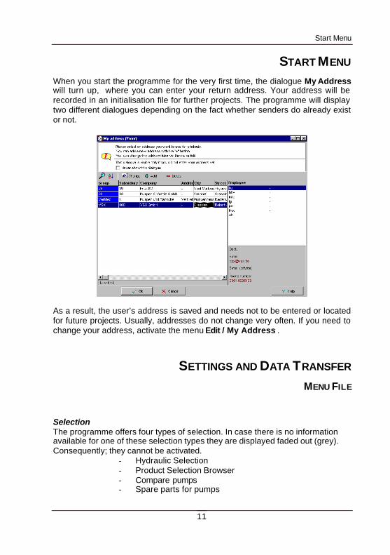
START MENU When you start the programme for the very first time, the dialogue My Address will turn up, where you can enter your return address. Your address will be recorded in an initialisation file for further projects. The programme will display two different dialogues depending on the fact whether senders do already exist or not.
As a result, the user’s address is saved and needs not to be entered or located for future projects. Usually, addresses do not change very often. If you need to change your address, activate the menu Edit / My Address .
SETTINGS AND DATA TRANSFER
MENU FILE
Selection The programme offers four types of selection. In case there is no information available for one of these selection types they are displayed faded out (grey). Consequently; they cannot be activated.
- Hydraulic Selection - Product Selection Browser - Compare pumps - Spare parts for pumps
Settings and Data Transfer
12
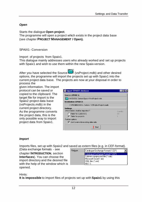
Open Starts the dialogue Open project. The programme will open a project which exists in the project data base (see chapter PROJECT MANAGEMENT / Open). SPAIX1- Conversion Import of projects from Spaix1. This dialogue mainly addresses users who already worked and set up projects with Spaix1 and wish to use them within the new Spaix-version.
After you have selected the Source (vsProject.mdb) and other desired options, the programme will import the projects set up with Spaix1 into the current project data base. The projects are now at your disposal in order to process the given information. The import protocol can be saved or copied to the clipboard. The target file for import is the Spaix2-project data base (vsProjects.mdb) in the current project directory. As the programme converts the project data, this is the only possible way to import project data from Spaix1.
Import Imports files, set up with Spaix2 and saved as extern files (e.g. in CEF-format). (Data exchange formats - see chapter INTRODUCTION, section Interfaces). You can choose the import directory and the desired file with the help of the window which is opened.
Hints: It is impossible to import files of projects set up with Spaix1 by using this
Settings and Data Transfer
13
option. If you wish to import files from Spaix 1 use the menu File/SPAIX1- Conversion. Export - As file: Exports the current project as file – saved in a chosen data exchange format (data exchange formats - see chapter INTRODUCTION, section Interfaces). - As e-mail : The current project will be sent as an e-mail in the chosen file format. (It is also possible to choose the PDF - Format.) You will find more information about the export of projects in chapter PROJECT MANAGEMENT/BUTTONS FUNCTIONS/Export project. Exit terminates the programme.
Settings and Data Transfer
14
MENU EDIT
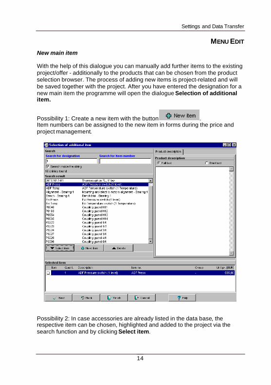
New main item With the help of this dialogue you can manually add further items to the existing project/offer - additionally to the products that can be chosen from the product selection browser. The process of adding new items is project-related and will be saved together with the project. After you have entered the designation for a new main item the programme will open the dialogue Selection of additional item.
Possibility 1: Create a new item with the button . Item numbers can be assigned to the new item in forms during the price and project management.
Possibility 2: In case accessories are already listed in the data base, the respective item can be chosen, highlighted and added to the project via the search function and by clicking Select item.
Settings and Data Transfer
15
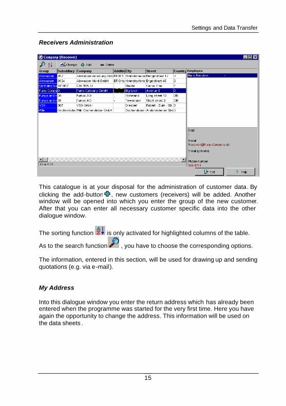
Receivers Administration
This catalogue is at your disposal for the administration of customer data. By clicking the add-button , new customers (receivers) will be added. Another window will be opened into which you enter the group of the new customer. After that you can enter all necessary customer specific data into the other dialogue window.
The sorting function is only activated for highlighted columns of the table.
As to the search function , you have to choose the corresponding options. The information, entered in this section, will be used for drawing up and sending quotations (e.g. via e-mail). My Address Into this dialogue window you enter the return address which has already been entered when the programme was started for the very first time. Here you have again the opportunity to change the address. This information will be used on the data sheets .
Settings and Data Transfer
16
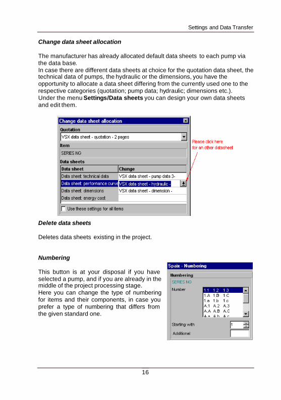
Change data sheet allocation The manufacturer has already allocated default data sheets to each pump via the data base. In case there are different data sheets at choice for the quotation data sheet, the technical data of pumps, the hydraulic or the dimensions, you have the opportunity to allocate a data sheet differing from the currently used one to the respective categories (quotation; pump data; hydraulic; dimensions etc.). Under the menu Settings/Data sheets you can design your own data sheets and edit them.
Delete data sheets Deletes data sheets existing in the project. Numbering This button is at your disposal if you have selected a pump, and if you are already in the middle of the project processing stage. Here you can change the type of numbering for items and their components, in case you prefer a type of numbering that differs from the given standard one.
Settings and Data Transfer
17
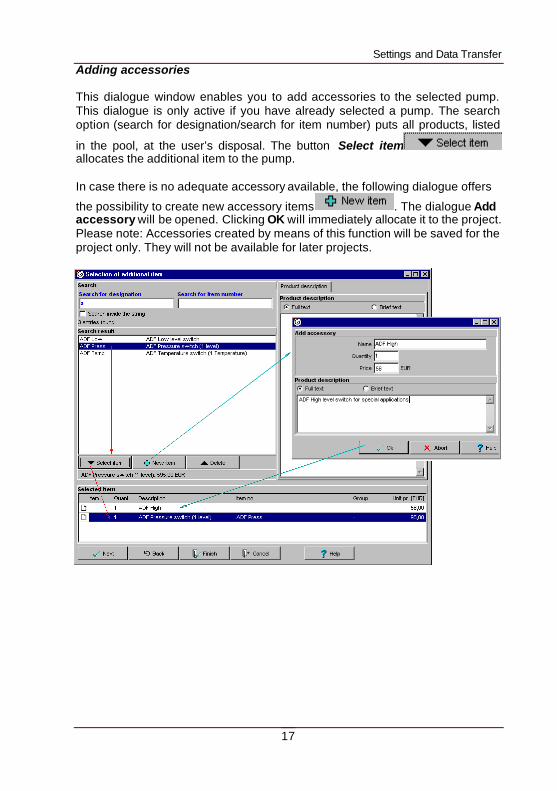
Adding accessories This dialogue window enables you to add accessories to the selected pump. This dialogue is only active if you have already selected a pump. The search option (search for designation/search for item number) puts all products, listed
in the pool, at the user’s disposal. The button Select item allocates the additional item to the pump. In case there is no adequate accessory available, the following dialogue offers
the possibility to create new accessory items . The dialogue Add accessory will be opened. Clicking OK will immediately allocate it to the project. Please note: Accessories created by means of this function will be saved for the project only. They will not be available for later projects.
Settings and Data Transfer
18
MENU SETTINGS
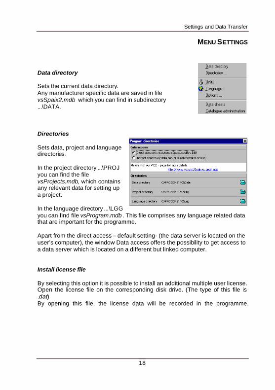
Data directory Sets the current data directory. Any manufacturer specific data are saved in file vsSpaix2.mdb which you can find in subdirectory ...\DATA. Directories Sets data, project and language directories. In the project directory ...\PROJ you can find the file vsProjects.mdb, which contains any relevant data for setting up a project. In the language directory ...\LGG you can find file vsProgram.mdb . This file comprises any language related data that are important for the programme. Apart from the direct access – default setting- (the data server is located on the user’s computer), the window Data access offers the possibility to get access to a data server which is located on a different but linked computer. Install license file By selecting this option it is possible to install an additional multiple user license. Open the license file on the corresponding disk drive. (The type of this file is .dat) By opening this file, the license data will be recorded in the programme.
Settings and Data Transfer
19
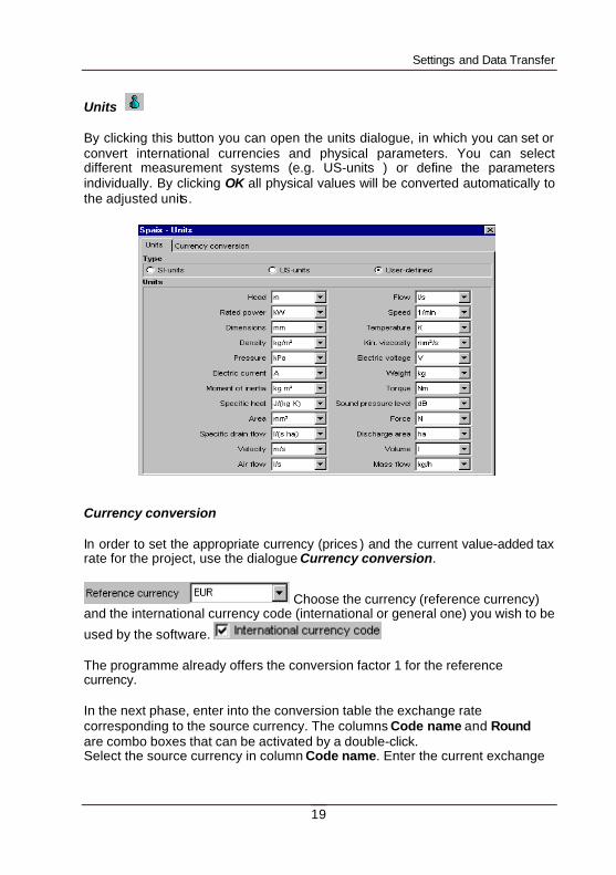
Units By clicking this button you can open the units dialogue, in which you can set or convert international currencies and physical parameters. You can select different measurement systems (e.g. US-units ) or define the parameters individually. By clicking OK all physical values will be converted automatically to the adjusted units.
Currency conversion In order to set the appropriate currency (prices ) and the current value-added tax rate for the project, use the dialogue Currency conversion.
Choose the currency (reference currency) and the international currency code (international or general one) you wish to be
used by the software. The programme already offers the conversion factor 1 for the reference currency. In the next phase, enter into the conversion table the exchange rate corresponding to the source currency. The columns Code name and Round are combo boxes that can be activated by a double-click. Select the source currency in column Code name. Enter the current exchange
Settings and Data Transfer
20
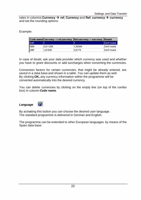
rates in columns Currency àà ref. Currency and Ref. currency àà currency and set the rounding options. Example: In case of doubt, ask your data provider which currency was used and whether you have to grant discounts or add surcharges when converting the currencies. Conversion factors for certain currencies, that might be already entered, are saved in a data base and shown in a table. You can update them as well. By clicking OK, any currency information within the programme will be converted automatically into the desired currency. You can delete currencies by clicking on the empty line (on top of the combo box) in column Code name. Language By activating this button you can choose the desired user language. The standard programme is delivered in German and English. The programme can be extended to other European languages by means of the Spaix data base.
Settings and Data Transfer
21
Options
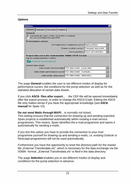
The page General enables the user to set different modes of display for performance curves, the conditions for the pump selection as well as for the standard allocation of certain data sheets . If you click ASCII- files after export... , the CEF-file will be opened immediately after the export process, in order to change the ASCII-Code. Editing the ASCII-file only makes sense if you have the appropriate knowledge (see ASCII-manual for Spaix V2). Do not send Mails through MAPI... is normally not ticked. This setting ensures that the connection for drawing up and sending exported Spaix projects is established automatically within existing e-mail service programmes. This means, Spaix identifies the e-mail programme and opens it automatically for sending e-mails. If you tick this option you have to provide the connection to your mail programme yourself for drawing up and sending e-mails, i.e. existing Outlook or Netscape-programmes will not be used automatically. Furthermore you have the opportunity to reset the directory path for the master file „External Transferdata.xls“, which is necessary for the data exchange via the VDMA –format. „External Transferdata.xls“ is filed in the data directory. The page Selection enables you to set different modes of display and conditions for the pump selection in advance.
Settings and Data Transfer
22
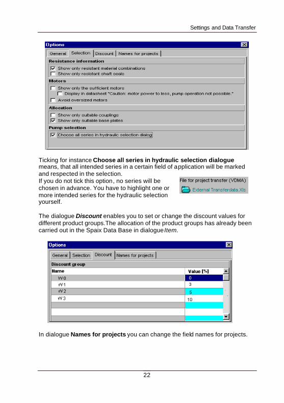
Ticking for instance Choose all series in hydraulic selection dialogue means, that all intended series in a certain field of application will be marked and respected in the selection. If you do not tick this option, no series will be chosen in advance. You have to highlight one or more intended series for the hydraulic selection yourself. The dialogue Discount enables you to set or change the discount values for different product groups.The allocation of the product groups has already been carried out in the Spaix Data Base in dialogue Item.
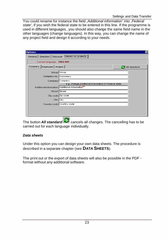
In dialogue Names for projects you can change the field names for projects.
Settings and Data Transfer
23
You could rename for instance the field ‚Additional information’ into ‚Federal state’, if you wish the federal state to be entered in this line. If the programme is used in different languages , you should also change the same field name in the other languages (change languages). In this way, you can change the name of any project field and design it according to your needs.
The button All standard cancels all changes. The cancelling has to be carried out for each language individually. Data sheets Under this option you can design your own data sheets. The procedure is described in a separate chapter (see DATA SHEETS). The print out or the export of data sheets will also be possible in the PDF - format without any additional software.
Settings and Data Transfer
24
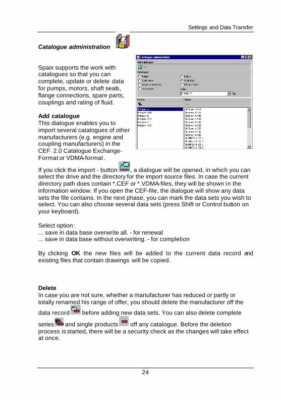
Catalogue administration Spaix supports the work with catalogues so that you can complete, update or delete data for pumps, motors, shaft seals, flange connections, spare parts, couplings and rating of fluid. Add catalogue This dialogue enables you to import several catalogues of other manufacturers (e.g. engine and coupling manufacturers) in the CEF 2.0 Catalogue Exchange-Format or VDMA-format .
If you click the import - button , a dialogue will be opened, in which you can select the drive and the directory for the import source files. In case the current directory path does contain *.CEF or *.VDMA-files, they will be shown in the information window. If you open the CEF-file, the dialogue will show any data sets the file contains. In the next phase, you can mark the data sets you wish to select. You can also choose several data sets (press Shift or Control button on your keyboard). Select option: ... save in data base overwrite all. - for renewal ... save in data base without overwriting. - for completion By clicking OK the new files will be added to the current data record and existing files that contain drawings will be copied. Delete In case you are not sure, whether a manufacturer has reduced or partly or totally renamed his range of offer, you should delete the manufacturer off the
data record before adding new data sets. You can also delete complete
series and single products off any catalogue. Before the deletion process is started, there will be a security check as the changes will take effect at once.
Settings and Data Transfer
25
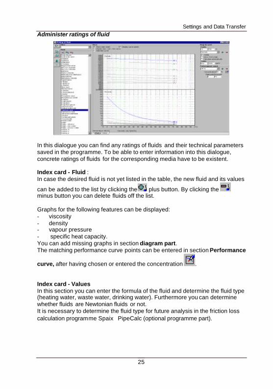
Administer ratings of fluid
In this dialogue you can find any ratings of fluids and their technical parameters saved in the programme. To be able to enter information into this dialogue, concrete ratings of fluids for the corresponding media have to be existent. Index card - Fluid : In case the desired fluid is not yet listed in the table, the new fluid and its values
can be added to the list by clicking the plus button. By clicking the minus button you can delete fluids off the list. Graphs for the following features can be displayed: - viscosity - density - vapour pressure - specific heat capacity. You can add missing graphs in section diagram part. The matching performance curve points can be entered in section Performance
curve, after having chosen or entered the concentration . Index card - Values In this section you can enter the formula of the fluid and determine the fluid type (heating water, waste water, drinking water). Furthermore you can determine whether fluids are Newtonian fluids or not. It is necessary to determine the fluid type for future analysis in the friction loss calculation programme Spaix PipeCalc (optional programme part).
Settings and Data Transfer
26
MENU EXTRAS
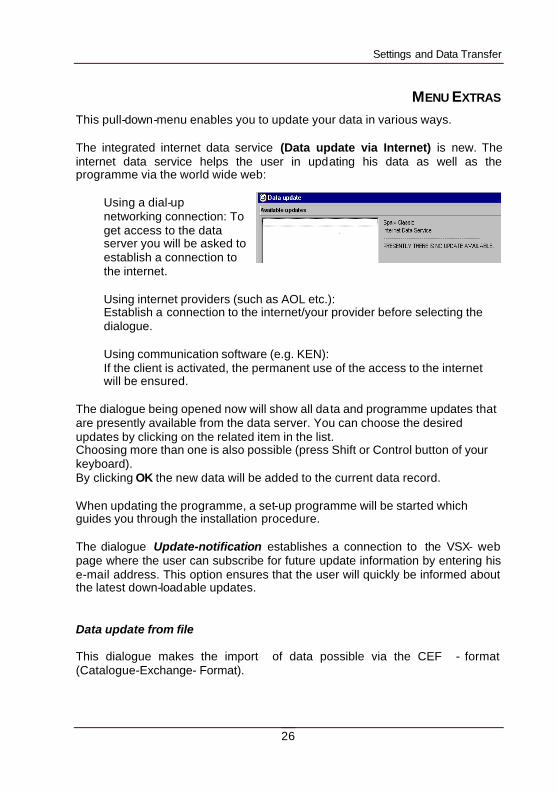
This pull-down-menu enables you to update your data in various ways. The integrated internet data service (Data update via Internet) is new. The internet data service helps the user in updating his data as well as the programme via the world wide web:
Using a dial-up networking connection: To get access to the data server you will be asked to establish a connection to the internet. Using internet providers (such as AOL etc.): Establish a connection to the internet/your provider before selecting the dialogue. Using communication software (e.g. KEN): If the client is activated, the permanent use of the access to the internet will be ensured.
The dialogue being opened now will show all data and programme updates that are presently available from the data server. You can choose the desired updates by clicking on the related item in the list. Choosing more than one is also possible (press Shift or Control button of your keyboard). By clicking OK the new data will be added to the current data record. When updating the programme, a set-up programme will be started which guides you through the installation procedure. The dialogue Update-notification establishes a connection to the VSX- web page where the user can subscribe for future update information by entering his e-mail address. This option ensures that the user will quickly be informed about the latest down-loadable updates. Data update from file This dialogue makes the import of data possible via the CEF - format (Catalogue-Exchange- Format).
Settings and Data Transfer
27
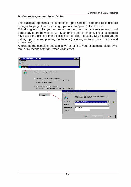
Project management Spaix Online This dialogue represents the interface to Spaix-Online. To be entitled to use this dialogue for project data exchange, you need a Spaix-Online license. This dialogue enables you to look for and to download customer requests and orders saved on the web server by an online search engine. These customers have used the online pump selection for sending requests. Spaix helps you in putting up the corresponding quotations (including customer tailed prices and accessory ). Afterwards the complete quotations will be sent to your customers, either by e-mail or by means of this interface via internet.
Hydraulic Selection
28
HYDRAULIC SELECTION Pumps can be chosen by different procedures.
In the Hydraulic Selection the suitable pump is selected considering the desired duty point, manufacturer specific areas of application and fluids .
In the Product Selection Browser pumps can be selected directly from the pump series .
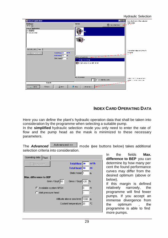
At the beginning you determine the frequency and the brand (Make). These options are only available if data of several pump manufacturers are saved in the data base. During the selection, the programme will consider all performance curves saved in the data base according to the activated frequency, or that are intended for a conversion to 50Hz or 60Hz. As a second step you enter the Area of application of the pump. On the right hand side of the window, the programme will display the Series available for the selected area of application. Highlight the series you want to be selected. By clicking the button Advanced (see buttons below) you can switch to a more comprehensive list of series parameters. You now have the opportunity to let the programme select pumps used in totally different areas of application and produced by different manufacturers. The button Select series, which will be additionally visible from now on, selects the series. The button Delete series removes them from the list. The manufacturers and the areas of application can be changed and the series can be chosen into the selection list just as you like. The standard view will be activated by clicking Simplified.
The button opens the duty chart view dialogue to get a better overview of all performance charts. After that you can determine the operating data.
Hydraulic Selection
29
INDEX CARD OPERATING DATA
Here you can define the plant’s hydraulic operation data that shall be taken into consideration by the programme when selecting a suitable pump. In the simplified hydraulic selection mode you only need to enter the rate of flow and the pump head as the mask is minimized to these necessary parameters.
The Advanced mode (see buttons below) takes additional selection criteria into consideration.
In the fields Max. difference to BEP you can determine by how many per cent the found performance curves may differ from the desired optimum (above or below). If this margin is defined relatively narrowly, the programme will find fewer pumps. If you accept an immense divergence from the optimum , the programme is able to find more pumps.
Hydraulic Selection
30
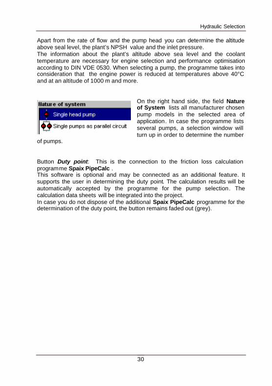
Apart from the rate of flow and the pump head you can determine the altitude above seal level, the plant’s NPSH value and the inlet pressure. The information about the plant’s altitude above sea level and the coolant temperature are necessary for engine selection and performance optimisation according to DIN VDE 0530. When selecting a pump, the programme takes into consideration that the engine power is reduced at temperatures above 40°C and at an altitude of 1000 m and more.
On the right hand side, the field Nature of System lists all manufacturer chosen pump models in the selected area of application. In case the programme lists several pumps, a selection window will turn up in order to determine the number
of pumps. Button Duty point: This is the connection to the friction loss calculation programme Spaix PipeCalc . This software is optional and may be connected as an additional feature. It supports the user in determining the duty point. The calculation results will be automatically accepted by the programme for the pump selection. The calculation data sheets will be integrated into the project. In case you do not dispose of the additional Spaix PipeCalc programme for the determination of the duty point, the button remains faded out (grey).
Hydraulic Selection
31
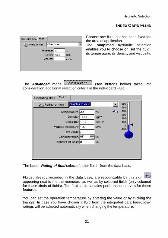
INDEX CARD FLUID
Choose one fluid that has been fixed for the area of application. The simplified hydraulic selection enables you to choose or set the fluid, its temperature, its density and viscosity.
The Advanced mode (see buttons below) takes into consideration additional selection criteria in the index card Fluid.
The button Rating of fluid selects further fluids from the data base.
Fluids , already recorded in the data base, are recognizable by this sign appearing next to the thermometer, as well as by coloured fields (only coloured for those kinds of fluids). The fluid table contains performance curves for these features. You can set the operation temperature by entering the value or by clicking the triangle. In case you have chosen a fluid from the integrated data base, other ratings will be adapted automatically when changing the temperature.
Hydraulic Selection
32
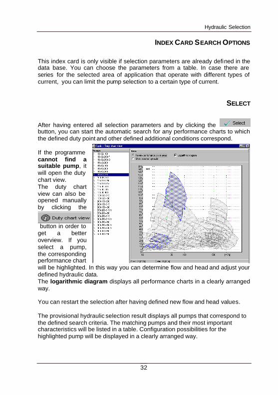
INDEX CARD SEARCH OPTIONS
This index card is only visible if selection parameters are already defined in the data base. You can choose the parameters from a table. In case there are series for the selected area of application that operate with different types of current, you can limit the pump selection to a certain type of current.
SELECT
After having entered all selection parameters and by clicking the button, you can start the automatic search for any performance charts to which the defined duty point and other defined additional conditions correspond. If the programme cannot find a suitable pump, it will open the duty chart view. The duty chart view can also be opened manually by clicking the
button in order to get a better overview. If you select a pump, the corresponding performance chart will be highlighted. In this way you can determine flow and head and adjust your defined hydraulic data. The logarithmic diagram displays all performance charts in a clearly arranged way. You can restart the selection after having defined new flow and head values. The provisional hydraulic selection result displays all pumps that correspond to the defined search criteria. The matching pumps and their most important characteristics will be listed in a table. Configuration possibilities for the highlighted pump will be displayed in a clearly arranged way.
Pump Selection Browser
33
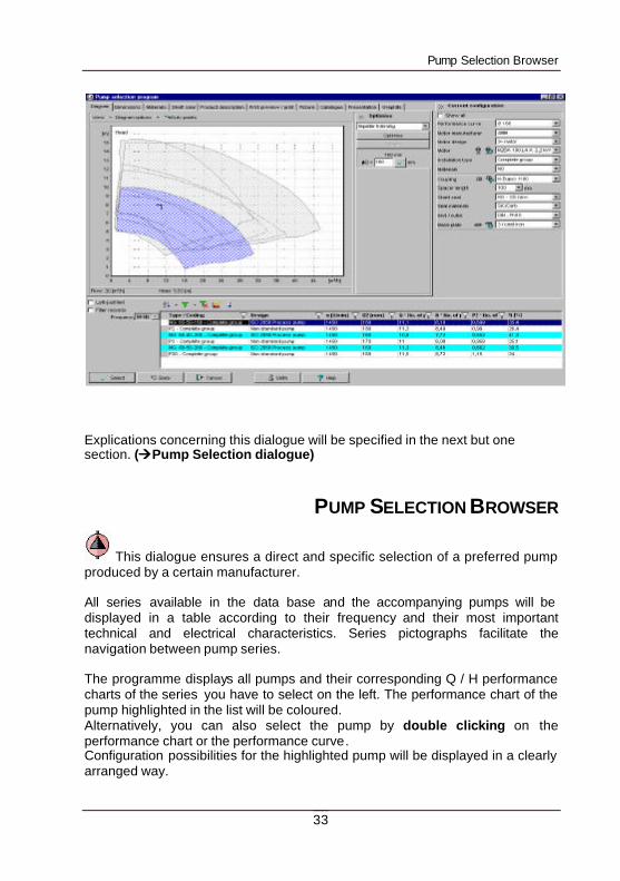
Explications concerning this dialogue will be specified in the next but one section. (ààPump Selection dialogue)
PUMP SELECTION BROWSER
This dialogue ensures a direct and specific selection of a preferred pump produced by a certain manufacturer. All series available in the data base and the accompanying pumps will be displayed in a table according to their frequency and their most important technical and electrical characteristics. Series pictographs facilitate the navigation between pump series. The programme displays all pumps and their corresponding Q / H performance charts of the series you have to select on the left. The performance chart of the pump highlighted in the list will be coloured. Alternatively, you can also select the pump by double clicking on the performance chart or the performance curve. Configuration possibilities for the highlighted pump will be displayed in a clearly arranged way.
Pump Selection Dialogue
34
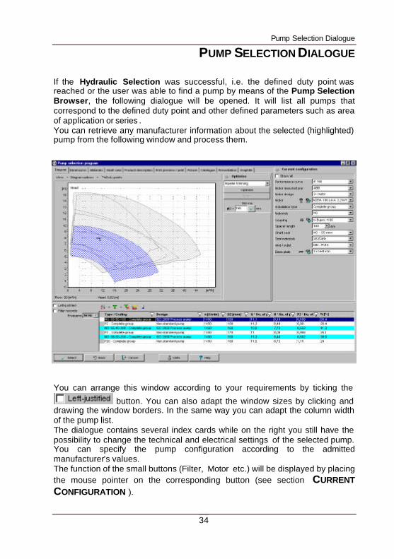
PUMP SELECTION DIALOGUE If the Hydraulic Selection was successful, i.e. the defined duty point was reached or the user was able to find a pump by means of the Pump Selection Browser, the following dialogue will be opened. It will list all pumps that correspond to the defined duty point and other defined parameters such as area of application or series . You can retrieve any manufacturer information about the selected (highlighted) pump from the following window and process them.
You can arrange this window according to your requirements by ticking the
button. You can also adapt the window sizes by clicking and drawing the window borders. In the same way you can adapt the column width of the pump list. The dialogue contains several index cards while on the right you still have the possibility to change the technical and electrical settings of the selected pump. You can specify the pump configuration according to the admitted manufacturer’s values. The function of the small buttons (Filter, Motor etc.) will be displayed by placing the mouse pointer on the corresponding button (see section CURRENT CONFIGURATION ).
Pump Selection Dialogue
35
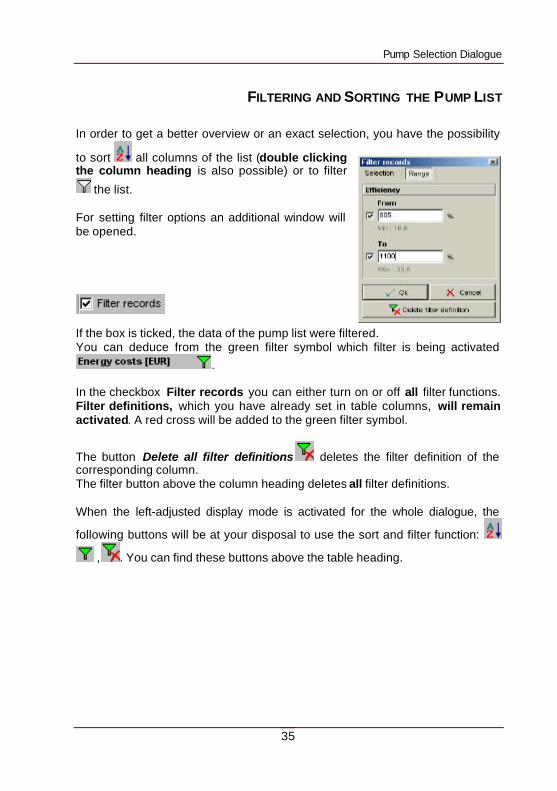
FILTERING AND SORTING THE PUMP LIST
In order to get a better overview or an exact selection, you have the possibility
to sort all columns of the list (double clicking the column heading is also possible) or to filter
the list. For setting filter options an additional window will be opened.
If the box is ticked, the data of the pump list were filtered. You can deduce from the green filter symbol which filter is being activated
. In the checkbox Filter records you can either turn on or off all filter functions. Filter definitions, which you have already set in table columns, will remain activated. A red cross will be added to the green filter symbol.
The button Delete all filter definitions deletes the filter definition of the corresponding column. The filter button above the column heading deletes all filter definitions. When the left-adjusted display mode is activated for the whole dialogue, the
following buttons will be at your disposal to use the sort and filter function:
, . You can find these buttons above the table heading.
Pump Selection Dialogue
36
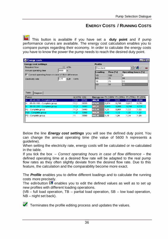
ENERGY COSTS / RUNNING COSTS
This button is available if you have set a duty point and if pump performance curves are available. The energy cost calculation enables you to compare pumps regarding their economy. In order to calculate the energy costs you have to know the power the pump needs to reach the desired duty point.
Below the line Energy cost settings you will see the defined duty point. You can change the annual operating time (the value of 5600 h represents a guideline). When setting the electricity rate, energy costs will be calculated or re-calculated in the table. If you tick the box – Correct operating hours in case of flow difference – the defined operating time at a desired flow rate will be adapted to the real pump flow rates as they often slightly deviate from the desired flow rate. Due to this feature, the calculation and the comparability become more exact. The Profile enables you to define different loadings and to calculate the running costs more precisely. The edit-button enables you to edit the defined values as well as to set up new profiles with different loading operations. (VB – full load operation, TB – partial load operation, SB – low load operation, NB – night set back).
Terminates the profile editing process and updates the values.
Pump Selection Dialogue
37
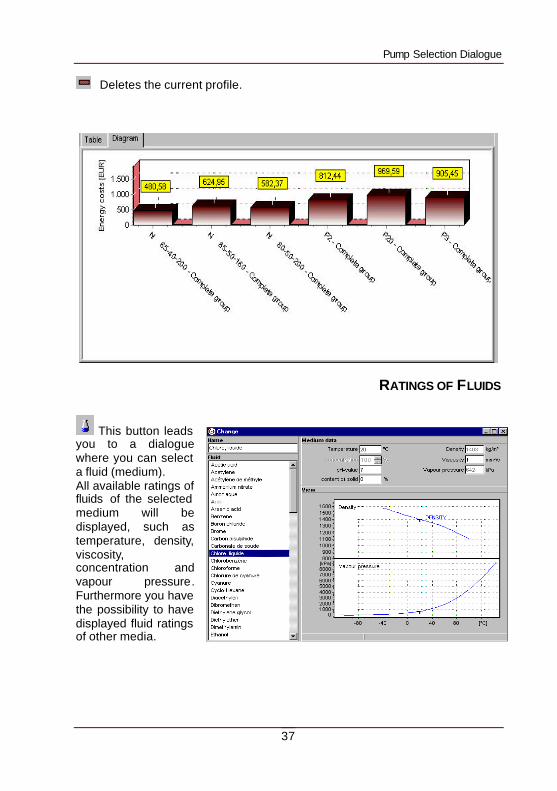
Deletes the current profile.
RATINGS OF FLUIDS
This button leads you to a dialogue where you can select a fluid (medium). All available ratings of fluids of the selected medium will be displayed, such as temperature, density, viscosity, concentration and vapour pressure. Furthermore you have the possibility to have displayed fluid ratings of other media.
Pump Selection Dialogue
38
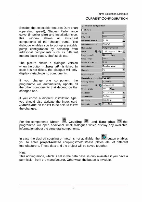
CURRENT CONFIGURATION
Besides the selectable features Duty chart (operating speed), Stages, Performance curve (impeller size) and Installation type, this window shows all structural components of the chosen pump. The dialogue enables you to put up a suitable pump configuration by selecting from additional components such as different motors, base plates, shaft seals etc. The picture shows a dialogue version when the button – Show all – is ticked. In case it is not ticked, the dialogue will only display variable pump components. If you change one component, the programme will automatically update all the other components that depend on the changed one. If you chose a different installation type, you should also activate the index card Dimensions on the left to be able to follow the changes.
For the components Motor , Coupling and Base plate the programme will open additional small dialogues which display any available information about the structural components.
In case the desired coupling or motor is not available, the button enables you to enter project-related couplings/motors/base plates etc. of different manufacturers. These data and the project will be saved together. Hint: This adding mode, which is set in the data base, is only available if you have a permission from the manufacturer. Otherwise, the button is invisible.
Pump Selection Dialogue
39
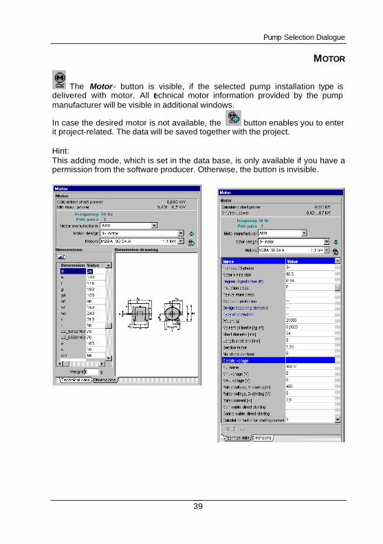
MOTOR
The Motor- button is visible, if the selected pump installation type is delivered with motor. All technical motor information provided by the pump manufacturer will be visible in additional windows.
In case the desired motor is not available, the button enables you to enter it project-related. The data will be saved together with the project. Hint: This adding mode, which is set in the data base, is only available if you have a permission from the software producer. Otherwise, the button is invisible.
Pump Selection Dialogue
40
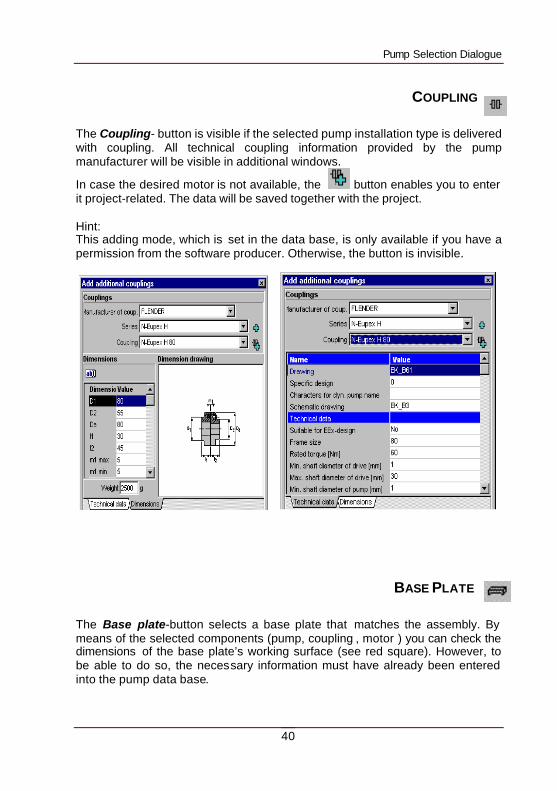
COUPLING
The Coupling- button is visible if the selected pump installation type is delivered with coupling. All technical coupling information provided by the pump manufacturer will be visible in additional windows.
In case the desired motor is not available, the button enables you to enter it project-related. The data will be saved together with the project. Hint: This adding mode, which is set in the data base, is only available if you have a permission from the software producer. Otherwise, the button is invisible.
BASE PLATE
The Base plate-button selects a base plate that matches the assembly. By means of the selected components (pump, coupling , motor ) you can check the dimensions of the base plate’s working surface (see red square). However, to be able to do so, the necessary information must have already been entered into the pump data base.
Pump Selection Dialogue
41
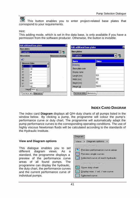
This button enables you to enter project-related base plates that correspond to your requirements. Hint: This adding mode, which is set in the data base, is only available if you have a permission from the software producer. Otherwise, the button is invisible.
INDEX CARD DIAGRAM The index card Diagram displays all Q/H-duty charts of all pumps listed in the window below. By clicking a pump, the programme will colour the pump’s performance curve or duty chart. The programme will automatically adapt the pump performance curves to the corresponding operating conditions. The use of highly viscous Newtonian fluids will be calculated according to the standards of the Hydraulic Institute. View and Diagram options This dialogue enables you to set different diagram views. As a standard, the programme displays a preview of the performance curve areas of all found pumps. The programme can display the hydraulic, the duty chart, the performance curves and the current performance curve of individual pumps.
Pump Selection Dialogue
42
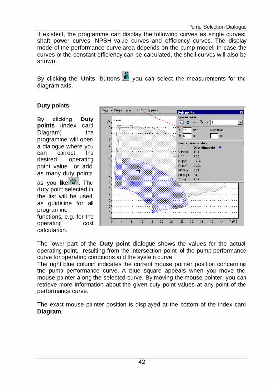
If existent, the programme can display the following curves as single curves: shaft power curves, NPSH-value curves and efficiency curves. The display mode of the performance curve area depends on the pump model. In case the curves of the constant efficiency can be calculated, the shell curves will also be shown.
By clicking the Units -buttons you can select the measurements for the diagram axis. Duty points By clicking Duty points (index card Diagram) the programme will open a dialogue where you can correct the desired operating point value or add as many duty points
as you like . The duty point selected in the list will be used as guideline for all programme functions, e.g. for the operating cost calculation. The lower part of the Duty point dialogue shows the values for the actual operating point, resulting from the intersection point of the pump performance curve for operating conditions and the system curve. The right blue column indicates the current mouse pointer position concerning the pump performance curve. A blue square appears when you move the mouse pointer along the selected curve. By moving the mouse pointer, you can retrieve more information about the given duty point values at any point of the performance curve. The exact mouse pointer position is displayed at the bottom of the index card Diagram.
Pump Selection Dialogue
43
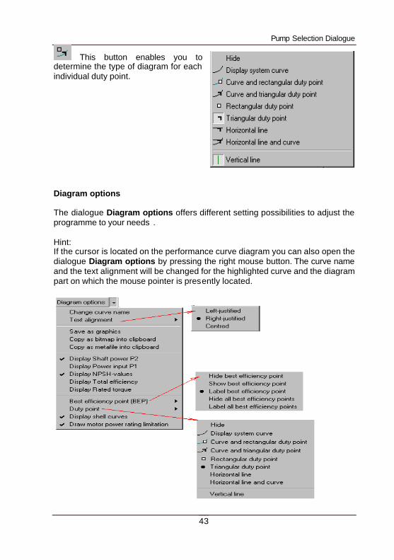
This button enables you to determine the type of diagram for each individual duty point. Diagram options The dialogue Diagram options offers different setting possibilities to adjust the programme to your needs . Hint: If the cursor is located on the performance curve diagram you can also open the dialogue Diagram options by pressing the right mouse button. The curve name and the text alignment will be changed for the highlighted curve and the diagram part on which the mouse pointer is presently located.
Pump Selection Dialogue
44
Via the option Change curve name you can change the name of the selected and therefore coloured performance curve. Furthermore, the current performance curve name can be arranged in different ways via Text alignment. You always have to open the dialogue Diagram options with the right mouse button for carrying out these two operations in order to determine the changes in the diagram part (Q/H values; shaft power or NPSH-values). Save as graphics – the following formats are possible: WMF, BMP or JPG. Concerning the dialogue Copy as bitmap into clipboard you should note that the scaling of the diagram depends on the fact, whether you have opened the whole window or just a normal window. The best efficiency point is the point with the best efficiency. It is displayed in form of a small square and shows the current efficiency if the option – Label best efficiency point – is activated. Here you can also choose different display modes. The programme either shows the duty point via the hydraulic selection or you can enter it into the pump selection window with the duty point dialogue. The dialogue that will be opened enables you to determine the display mode of each single duty point. Draw motor power rating limitation will show the performance curve sections in a broken line in which the motor power is insufficient. If you have not chosen this option, the whole performance curve will be shown as a continuous line (see also illustration below). Water curves represent reference performance curves which are saved in the data base. They enable you to compare the converted performance curves when pumping highly viscous fluids.
Pump Selection Dialogue
45
Correct curve
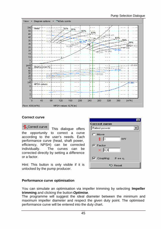
This dialogue offers the opportunity to correct a curve according to the user’s needs. Each performance curve (head, shaft power, efficiency, NPSH) can be corrected individually. The curves can be corrected directly by setting a difference or a factor. Hint: This button is only visible if it is unlocked by the pump producer. Performance curve optimisation You can simulate an optimisation via impeller trimming by selecting Impeller trimming and clicking the button Optimise. The programme will suggest the ideal diameter between the minimum and maximum impeller diameter and respect the given duty point. The optimised performance curve will be entered into the duty chart.
Pump Selection Dialogue
46
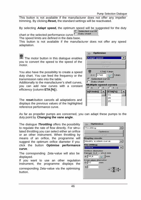
This button is not available if the manufacturer does not offer any impeller trimming. By clicking Reset, the standard settings will be reactivated. By selecting Adapt speed, the optimum speed will be suggested for the duty
chart or the selected performance curve . The speed limits are defined in the data base. This button is not available if the manufacturer does not offer any speed adaptation.
The motor button in this dialogue enables you to convert the speed to the speed of the motor. You also have the possibility to create a speed duty chart. You can feed the frequency or the transmission ratio into the table. Additionally to the manufacturer’s shell curves, you can add new curves with a constant efficiency (column ETA [%] ). The reset-button cancels all adaptations and displays the previous values of the highlighted reference performance curve. As far as propeller pumps are concerned, you can adapt these pumps to the duty point by Changing the vane angle. The dialogue Throttling offers the possibility to regulate the rate of flow directly. For simu-lated throttling you can select either an orifice or an other instrument. When throttling by means of an orifice, the programme will suggest the optimum orifice diameter if you click the button Optimise performance curve. The corresponding Zeta-value will also be displayed. If you want to use an other regulation instrument, the programme displays the
corresponding Zeta-value via the optimising button.
Pump Selection Dialogue
47
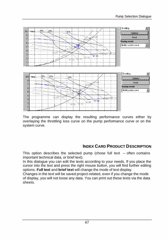
The programme can display the resulting performance curves either by overlaying the throttling loss curve on the pump performance curve or on the system curve.
INDEX CARD PRODUCT DESCRIPTION
This option describes the selected pump (chose full text – often contains important technical data, or brief text). In this dialogue you can edit the texts according to your needs. If you place the cursor into the text and press the right mouse button, you will find further editing options. Full text and brief text will change the mode of text display. Changes in the text will be saved project-related, even if you change the mode of display, you will not loose any data. You can print out these texts via the data sheets.
Pump Selection Dialogue
48
INDEX CARD DIMENSIONS
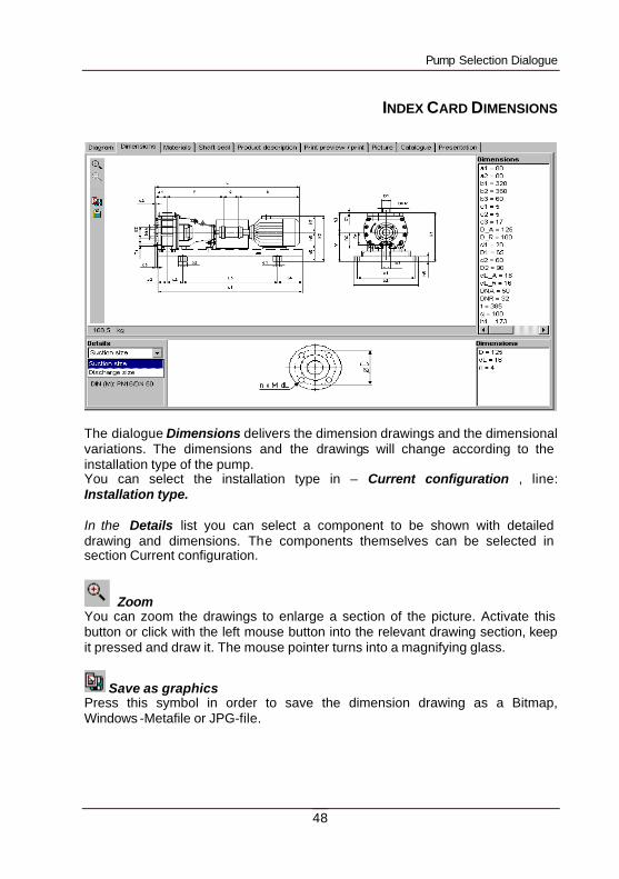
The dialogue Dimensions delivers the dimension drawings and the dimensional variations. The dimensions and the drawings will change according to the installation type of the pump. You can select the installation type in – Current configuration , line: Installation type. In the Details list you can select a component to be shown with detailed drawing and dimensions. The components themselves can be selected in section Current configuration.
Zoom You can zoom the drawings to enlarge a section of the picture. Activate this button or click with the left mouse button into the relevant drawing section, keep it pressed and draw it. The mouse pointer turns into a magnifying glass.
Save as graphics Press this symbol in order to save the dimension drawing as a Bitmap, Windows -Metafile or JPG-file.
Pump Selection Dialogue
49
Copy to clipboard Copies dimension drawing to the Windows clipboard. You can insert it I your graphic or word processing software by using menu Edit/Paste.
INDEX CARD MATERIALS
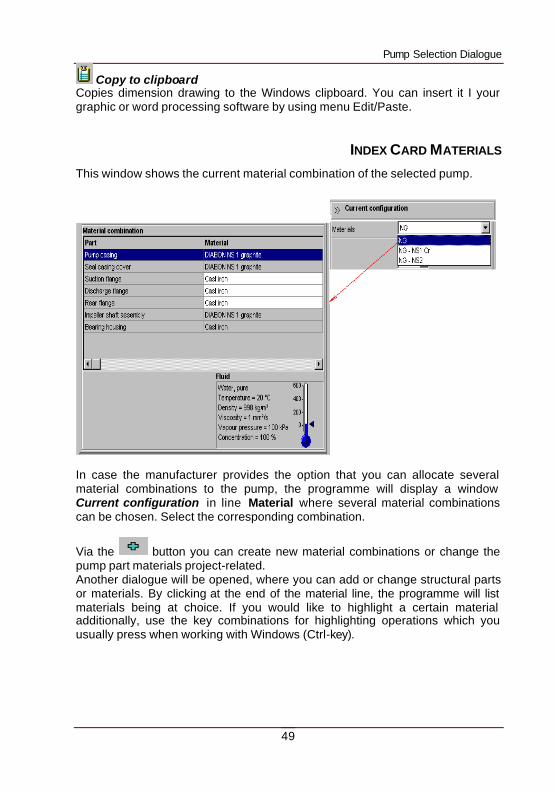
This window shows the current material combination of the selected pump.
In case the manufacturer provides the option that you can allocate several material combinations to the pump, the programme will display a window Current configuration in line Material where several material combinations can be chosen. Select the corresponding combination.
Via the button you can create new material combinations or change the pump part materials project-related. Another dialogue will be opened, where you can add or change structural parts or materials. By clicking at the end of the material line, the programme will list materials being at choice. If you would like to highlight a certain material additionally, use the key combinations for highlighting operations which you usually press when working with Windows (Ctrl-key).
Pump Selection Dialogue
50
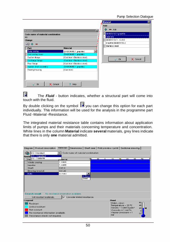
The Fluid - button indicates, whether a structural part will come into touch with the fluid.
By double clicking on the symbol you can change this option for each part individually. This information will be used for the analysis in the programme part Fluid -Material -Resistance.
The integrated material resistance table contains information about application limits of pumps and their materials concerning temperature and concentration. White lines in the column Material indicate several materials, grey lines indicate that there is only one material admitted.
Pump Selection Dialogue
51
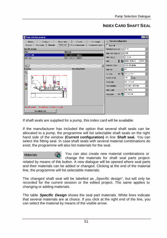
INDEX CARD SHAFT SEAL
If shaft seals are supplied for a pump, this index card will be available. If the manufacturer has included the option that several shaft seals can be allocated to a pump, the programme will list selectable shaft seals on the right hand side of the window (Current configuration) in line Shaft seal. You can select the fitting seal. In case shaft seals with several material combinations do exist, the programme will also list materials for the seal.
You can also create new material combinations or change the materials for shaft seal parts project-
related by means of this button. A new dialogue will be opened where seal parts and their materials can be added or changed. Clicking at the end of the material line, the programme will list selectable materials. The changed shaft seal will be labelled as „Specific design“, but will only be recorded for the current session or the edited project. The same applies to changing or adding materials. The table Specific Design shows the seal part materials. White lines indicate that several materials are at choice. If you click at the right end of the line, you can select the material by means of the visible arrow.
Pump Selection Dialogue
52
By pressing the button „Set suitable seal“, you will get a search result if the data base contains resistance information about shaft seals (e.g. fluids and their characteristics, temperature, concentration , materials and their characteristics.
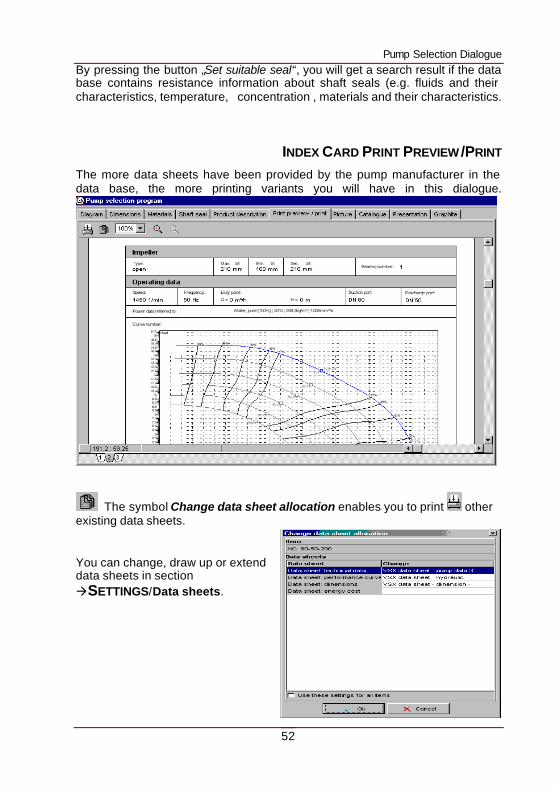
INDEX CARD PRINT PREVIEW /PRINT
The more data sheets have been provided by the pump manufacturer in the data base, the more printing variants you will have in this dialogue.
The symbol Change data sheet allocation enables you to print other existing data sheets. You can change, draw up or extend data sheets in section àSETTINGS/Data sheets.
Accessory Selection
53
USER-DEFINED PAGES
The manufacturer has the option to provide additional pages for the pump dialogue. These pages may contain for example the terminal plan, the photo of the pump or the schematic drawing of the pump. The catalogue or a presentation can be displayed by means of the Acrobat-Reader. The number of index cards, at your disposal in the pump selection catalogue, is therefore different as it depends on the manufacturers and their pumps.
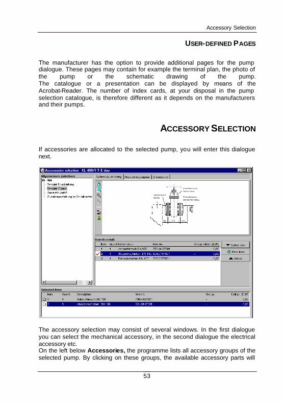
ACCESSORY SELECTION If accessories are allocated to the selected pump, you will enter this dialogue next.
The accessory selection may consist of several windows. In the first dialogue you can select the mechanical accessory, in the second dialogue the electrical accessory etc. On the left below Accessories, the programme lists all accessory groups of the selected pump. By clicking on these groups, the available accessory parts will
Accessory Selection
54
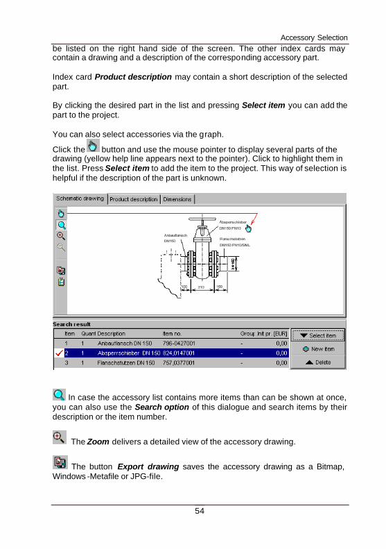
be listed on the right hand side of the screen. The other index cards may contain a drawing and a description of the corresponding accessory part. Index card Product description may contain a short description of the selected part. By clicking the desired part in the list and pressing Select item you can add the part to the project. You can also select accessories via the graph.
Click the button and use the mouse pointer to display several parts of the drawing (yellow help line appears next to the pointer). Click to highlight them in the list. Press Select item to add the item to the project. This way of selection is helpful if the description of the part is unknown.
In case the accessory list contains more items than can be shown at once, you can also use the Search option of this dialogue and search items by their description or the item number.
The Zoom delivers a detailed view of the accessory drawing.
The button Export drawing saves the accessory drawing as a Bitmap, Windows -Metafile or JPG-file.
55
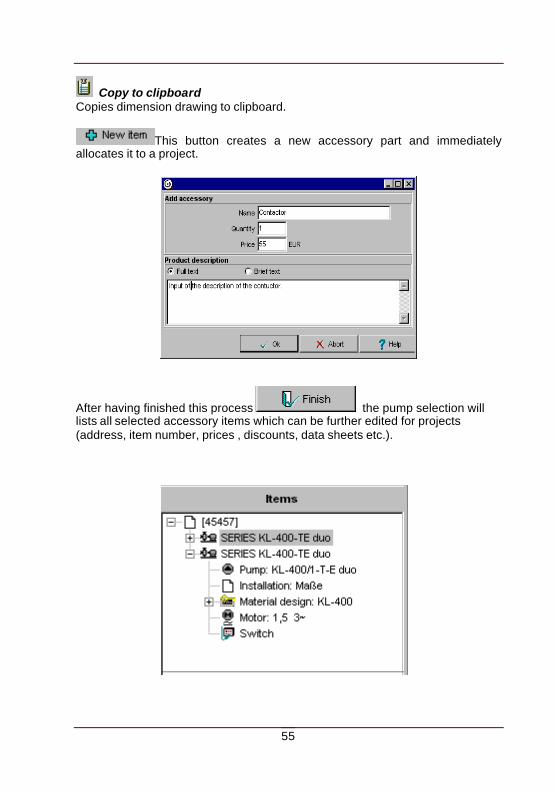
Copy to clipboard Copies dimension drawing to clipboard.
This button creates a new accessory part and immediately allocates it to a project.
After having finished this process the pump selection will lists all selected accessory items which can be further edited for projects (address, item number, prices , discounts, data sheets etc.).
56
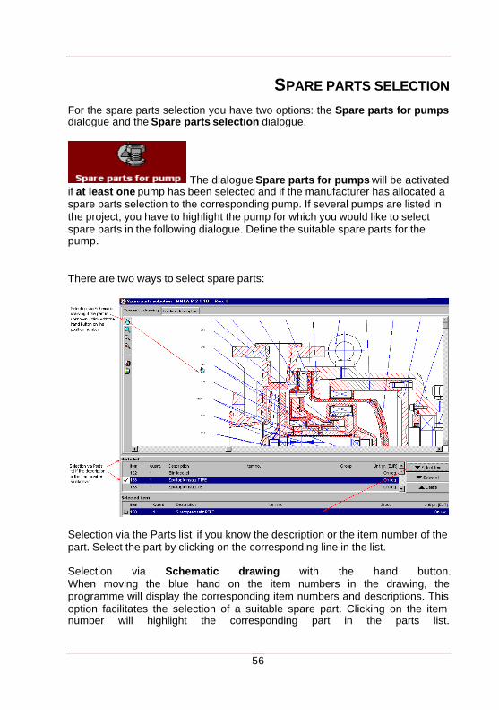
SPARE PARTS SELECTION For the spare parts selection you have two options: the Spare parts for pumps dialogue and the Spare parts selection dialogue.
The dialogue Spare parts for pumps will be activated if at least one pump has been selected and if the manufacturer has allocated a spare parts selection to the corresponding pump. If several pumps are listed in the project, you have to highlight the pump for which you would like to select spare parts in the following dialogue. Define the suitable spare parts for the pump. There are two ways to select spare parts:
Selection via the Parts list if you know the description or the item number of the part. Select the part by clicking on the corresponding line in the list. Selection via Schematic drawing with the hand button. When moving the blue hand on the item numbers in the drawing, the programme will display the corresponding item numbers and descriptions. This option facilitates the selection of a suitable spare part. Clicking on the item number will highlight the corresponding part in the parts list.
Spare parts selection
57
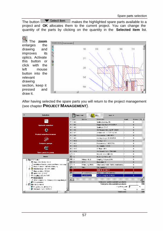
The button makes the highlighted spare parts available to a project and OK allocates them to the current project. You can change the quantity of the parts by clicking on the quantity in the Selected item list.
The zoom enlarges the drawing and improves its optics. Activate this button or click with the left mouse button into the relevant drawing section, keep it pressed and draw it. After having selected the spare parts you will return to the project management (see chapter PROJECT MANAGEMENT) .
58
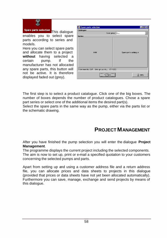
This dialogue enables you to select spare parts according to series and models. Here you can select spare parts and allocate them to a project without having selected a certain pump. If the manufacturer has not allocated any spare parts, this button will not be active. It is therefore displayed faded out (grey). The first step is to select a product catalogue. Click one of the big boxes. The number of boxes depends the number of product catalogues. Chose a spare part series or select one of the additional items the desired part(s). Select the spare parts in the same way as the pump, either via the parts list or the schematic drawing.
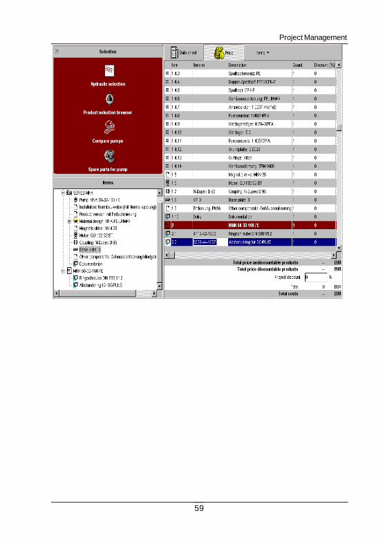
PROJECT MANAGEMENT After you have finished the pump selection you will enter the dialogue Project Management. The programme displays the current project including the selected components. The aim is now to set up, print or e-mail a specified quotation to your customers concerning the selected pumps and parts. Apart from setting up and using a customer address file and a return address file, you can allocate prices and data sheets to projects in this dialogue (provided that prices or data sheets have not yet been allocated automatically). Furthermore you can save, manage, exchange and send projects by means of this dialogue.
Project Management
59
Project Management
60
BUTTONS - FUNCTIONS
You can also find the following button functions in the pull down menus File and Settings .
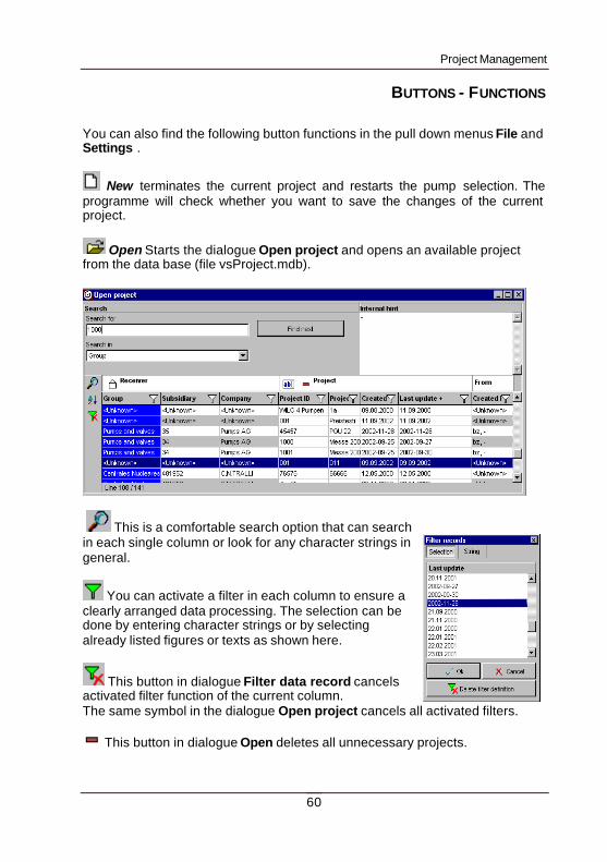
New terminates the current project and restarts the pump selection. The programme will check whether you want to save the changes of the current project.
Open Starts the dialogue Open project and opens an available project from the data base (file vsProject.mdb).
This is a comfortable search option that can search in each single column or look for any character strings in general.
You can activate a filter in each column to ensure a clearly arranged data processing. The selection can be done by entering character strings or by selecting already listed figures or texts as shown here.
This button in dialogue Filter data record cancels activated filter function of the current column. The same symbol in the dialogue Open project cancels all activated filters.
This button in dialogue Open deletes all unnecessary projects.
Project Management
61
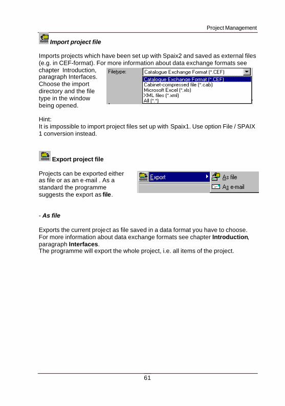
Import project file Imports projects which have been set up with Spaix2 and saved as external files (e.g. in CEF-format). For more information about data exchange formats see chapter Introduction, paragraph Interfaces. Choose the import directory and the file type in the window being opened. Hint: It is impossible to import project files set up with Spaix1. Use option File / SPAIX 1 conversion instead.
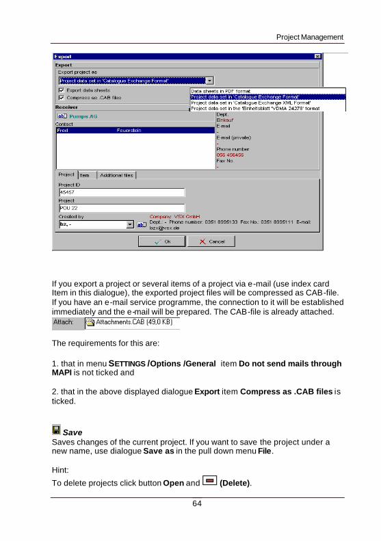
Export project file Projects can be exported either as file or as an e-mail . As a standard the programme suggests the export as file. - As file Exports the current project as file saved in a data format you have to choose. For more information about data exchange formats see chapter Introduction, paragraph Interfaces. The programme will export the whole project, i.e. all items of the project.
Project Management
62
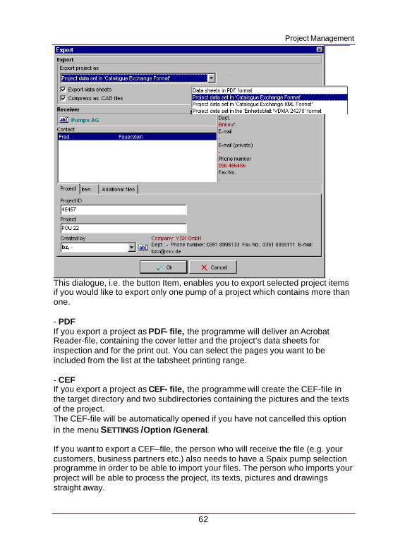
This dialogue, i.e. the button Item, enables you to export selected project items if you would like to export only one pump of a project which contains more than one. - PDF If you export a project as PDF- file, the programme will deliver an Acrobat Reader-file, containing the cover letter and the project’s data sheets for inspection and for the print out. You can select the pages you want to be included from the list at the tabsheet printing range. - CEF If you export a project as CEF- file, the programme will create the CEF-file in the target directory and two subdirectories containing the pictures and the texts of the project. The CEF-file will be automatically opened if you have not cancelled this option in the menu SETTINGS /Option /General. If you want to export a CEF–file, the person who will receive the file (e.g. your customers, business partners etc.) also needs to have a Spaix pump selection programme in order to be able to import your files. The person who imports your project will be able to process the project, its texts, pictures and drawings straight away.
Project Management
63
The CEF- format is an ASCII-format which may contain all pieces of information about the selected pump (performance curves, technical data, accessory and price information). For detailed information about the ASCII-format the ASCII-manual about the CEF- interface will be at your disposal as documentation. - CEF-XML The CEF-XML-format creates an XML-file that is based on the CEF-file format. The CEF-XML-file will be automatically opened, if you have not cancelled this option in the menu SETTINGS /Option /General. - VDMA If you export files in the VDMA–format the programme will create an xls-file in the defined directory. The xls-file only contains performance curve information and a few technical data of the selected pump. Information about the assembly, drawings, dimensions, accessory or prices will not be saved. Please note: It is impossible to restore the complete project from a VDMA file, since it does not contain the complete information. - As e-mail : The current project will be sent as an e-mail in the selected file format. (You can choose the same formats as in Export files.)
Project Management
64
If you export a project or several items of a project via e-mail (use index card Item in this dialogue), the exported project files will be compressed as CAB-file. If you have an e-mail service programme, the connection to it will be established immediately and the e-mail will be prepared. The CAB-file is already attached.
The requirements for this are: 1. that in menu SETTINGS /Options /General item Do not send mails through MAPI is not ticked and 2. that in the above displayed dialogue Export item Compress as .CAB files is ticked.
Save Saves changes of the current project. If you want to save the project under a new name, use dialogue Save as in the pull down menu File. Hint:
To delete projects click button Open and (Delete).
Project Management
65
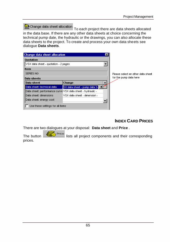
To each project there are data sheets allocated in the data base. If there are any other data sheets at choice concerning the technical pump date, the hydraulic or the drawings, you can also allocate these data sheets to the project. To create and process your own data sheets see dialogue Data sheets.
INDEX CARD PRICES
There are two dialogues at your disposal: Data sheet and Price .
The button lists all project components and their corresponding prices.
Project Management
66
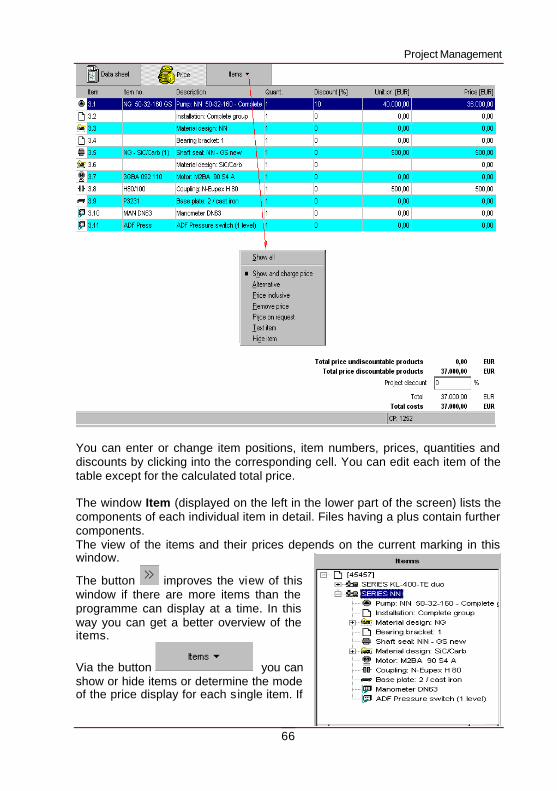
You can enter or change item positions, item numbers, prices, quantities and discounts by clicking into the corresponding cell. You can edit each item of the table except for the calculated total price. The window Item (displayed on the left in the lower part of the screen) lists the components of each individual item in detail. Files having a plus contain further components. The view of the items and their prices depends on the current marking in this window.
The button improves the view of this window if there are more items than the programme can display at a time. In this way you can get a better overview of the items.
Via the button you can show or hide items or determine the mode of the price display for each single item. If
Project Management
67
you decide for instance to give away a motor for free, click Price inclusive.
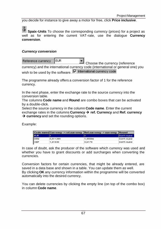
Spaix-Units To choose the corresponding currency (prices) for a project as well as for entering the current VAT-rate, use the dialogue Currency conversion. Currency conversion
Choose the currency (reference currency) and the international currency code (international or general one) you
wish to be used by the software. The programme already offers a conversion factor of 1 for the reference currency. In the next phase, enter the exchange rate to the source currency into the conversion table. The columns Code name and Round are combo boxes that can be activated by a double-click. Select the source currency in the column Code name. Enter the current exchange rates in the columns Currency àà ref. Currency and Ref. currency àà currency and set the rounding options. Example: In case of doubt, ask the producer of the software which currency was used and whether you have to grant discounts or add surcharges when converting the currencies. Conversion factors for certain currencies, that might be already entered, are saved in a data base and shown in a table. You can update them as well. By clicking OK any currency information within the programme will be converted automatically into the desired currency. You can delete currencies by clicking the empty line (on top of the combo box) in column Code name.
Project Management
68
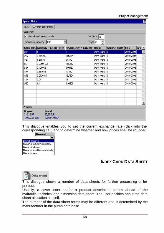
This dialogue enables you to set the current exchange rate (click into the corresponding cell) and to determine whether and how prices shall be rounded.
INDEX CARD DATA SHEET
This dialogue shows a number of data sheets for further processing or for printout. Usually, a cover letter and/or a product description comes ahead of the hydraulic, technical and dimension data sheet. The user decides about the data sheet allocation himself. The number of the data sheet forms may be different and is determined by the manufacturer in the pump data base.
Project Management
69
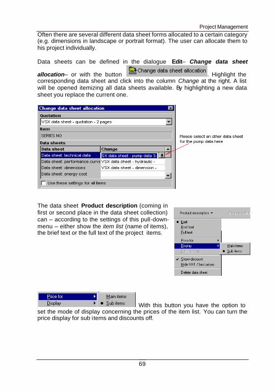
Often there are several different data sheet forms allocated to a certain category (e.g. dimensions in landscape or portrait format). The user can allocate them to his project individually. Data sheets can be defined in the dialogue Edit– Change data sheet
allocation– or with the button . Highlight the corresponding data sheet and click into the column Change at the right. A list will be opened itemizing all data sheets available. By highlighting a new data sheet you replace the current one.
The data sheet Product description (coming in first or second place in the data sheet collection) can – according to the settings of this pull-down-menu – either show the item list (name of items), the brief text or the full text of the project items.
With this button you have the option to set the mode of display concerning the prices of the item list. You can turn the price display for sub i tems and discounts off.
Project Management
70
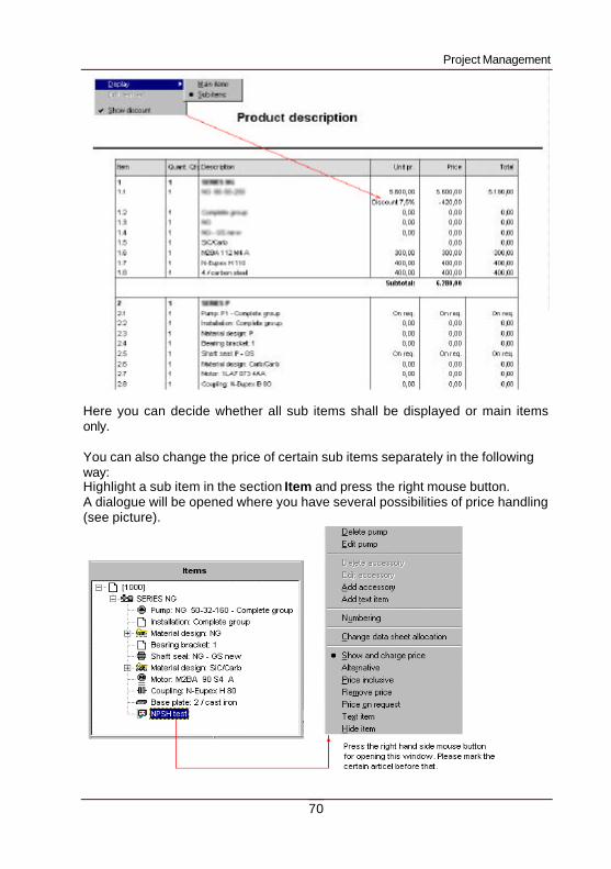
Here you can decide whether all sub items shall be displayed or main items only. You can also change the price of certain sub items separately in the following way: Highlight a sub item in the section Item and press the right mouse button. A dialogue will be opened where you have several possibilities of price handling (see picture).
Project Management
71
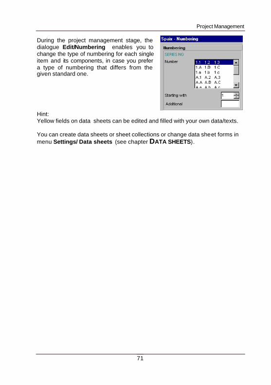
During the project management stage, the dialogue Edit/Numbering enables you to change the type of numbering for each single item and its components, in case you prefer a type of numbering that differs from the given standard one. Hint: Yellow fields on data sheets can be edited and filled with your own data/texts. You can create data sheets or sheet collections or change data sheet forms in menu Settings/ Data sheets (see chapter DATA SHEETS).
Create and Edit Data Sheets
72
CREATE AND EDIT DATA SHEETS
The dialogue for creating and editing data sheets can be found in the pull down menu Settings / Data sheets. Some general points Every single data sheet consists of several pages. Each page is displayed individually on a separate index card. The pages again are composed of several layers. The layers can be processed individually. They lay one on top of the other like transparent foils. Only one of the layers is active at a time and which then can be edited. Non-active layer s are displayed faded out. The advantage of subdividing documents into layers is, that those layers can be linked to several documents without explicitly copying them. Therefore the layers are saved in a central layer pool in order to have them available for use by several data sheet s.
MENU FILE
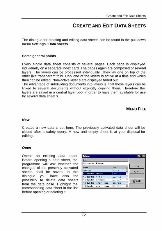
New Creates a new data sheet form. The previously activated data sheet will be closed after a safety query. A new and empty sheet is at your disposal for editing. Open Opens an existing data sheet. Before opening a data sheet, the programme will ask whether the changes of the presently activated sheets shall be saved. In this dialogue you have also the possibility to delete data sheets from the data base. Highlight the corresponding data sheet in the list before opening or deleting it.
Create and Edit Data Sheets
73
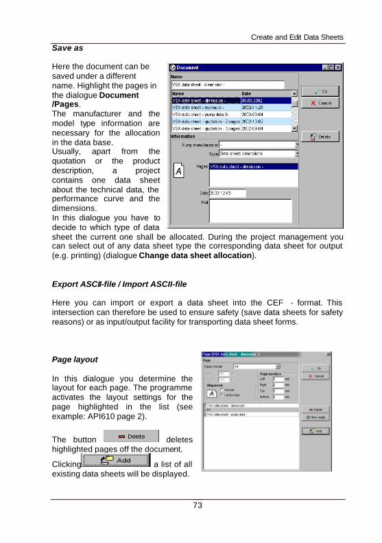
Save as Here the document can be saved under a different name. Highlight the pages in the dialogue Document /Pages. The manufacturer and the model type information are necessary for the allocation in the data base. Usually, apart from the quotation or the product description, a project contains one data sheet about the technical data, the performance curve and the dimensions. In this dialogue you have to decide to which type of data sheet the current one shall be allocated. During the project management you can select out of any data sheet type the corresponding data sheet for output (e.g. printing) (dialogue Change data sheet allocation). Export ASCII-file / Import ASCII-file Here you can import or export a data sheet into the CEF - format. This intersection can therefore be used to ensure safety (save data sheets for safety reasons) or as input/output facility for transporting data sheet forms. Page layout In this dialogue you determine the layout for each page. The programme activates the layout settings for the page highlighted in the list (see example: API610 page 2).
The button deletes highlighted pages off the document.
Clicking a list of all existing data sheets will be displayed.
Create and Edit Data Sheets
74
If you highlight a sheet in the list, its pages will be added to the current data sheet.
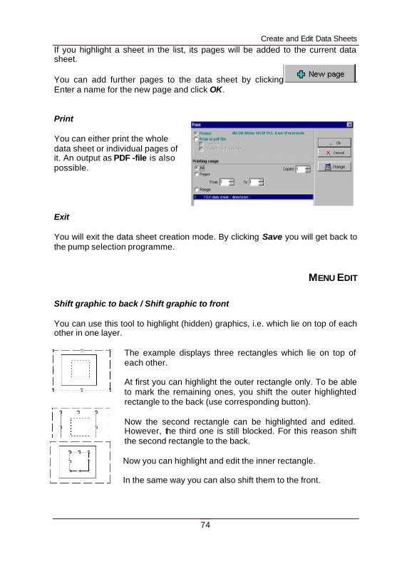
You can add further pages to the data sheet by clicking . Enter a name for the new page and click OK. Print You can either print the whole data sheet or individual pages of it. An output as PDF -file is also possible. Exit You will exit the data sheet creation mode. By clicking Save you will get back to the pump selection programme.
MENU EDIT
Shift graphic to back / Shift graphic to front You can use this tool to highlight (hidden) graphics, i.e. which lie on top of each other in one layer.
The example displays three rectangles which lie on top of each other. At first you can highlight the outer rectangle only. To be able to mark the remaining ones, you shift the outer highlighted rectangle to the back (use corresponding button). Now the second rectangle can be highlighted and edited. However, the third one is still blocked. For this reason shift the second rectangle to the back. Now you can highlight and edit the inner rectangle. In the same way you can also shift them to the front.
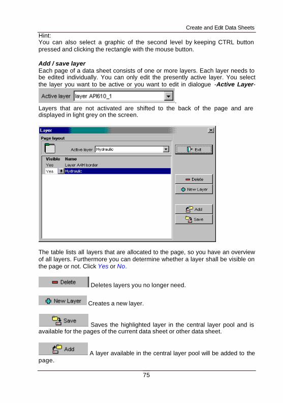
Create and Edit Data Sheets
75
Hint: You can also select a graphic of the second level by keeping CTRL button pressed and clicking the rectangle with the mouse button. Add / save layer Each page of a data sheet consists of one or more layers. Each layer needs to be edited individually. You can only edit the presently active layer. You select the layer you want to be active or you want to edit in dialogue -Active Layer-
. Layers that are not activated are shifted to the back of the page and are displayed in light grey on the screen.
The table lists all layers that are allocated to the page, so you have an overview of all layers. Furthermore you can determine whether a layer shall be visible on the page or not. Click Yes or No.
Deletes layers you no longer need.
Creates a new layer.
Saves the highlighted layer in the central layer pool and is available for the pages of the current data sheet or other data sheet.
A layer available in the central layer pool will be added to the page.
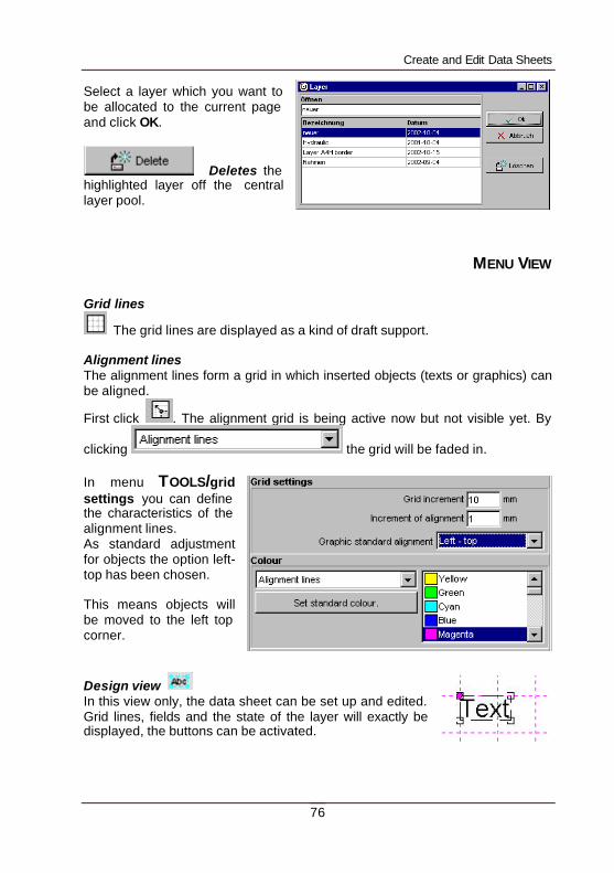
Create and Edit Data Sheets
76
Select a layer which you want to be allocated to the current page and click OK.
Deletes the highlighted layer off the central layer pool.
MENU VIEW
Grid lines
The grid lines are displayed as a kind of draft support. Alignment lines The alignment lines form a grid in which inserted objects (texts or graphics) can be aligned.
First click . The alignment grid is being active now but not visible yet. By
clicking the grid will be faded in. In menu TOOLS/grid settings you can define the characteristics of the alignment lines. As standard adjustment for objects the option left-top has been chosen. This means objects will be moved to the left top corner.
Design view In this view only, the data sheet can be set up and edited. Grid lines, fields and the state of the layer will exactly be displayed, the buttons can be activated.
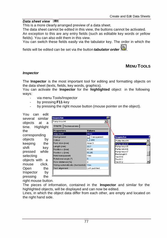
Create and Edit Data Sheets
77
Data sheet view This is a more clearly arranged preview of a data sheet. The data sheet cannot be edited in this view, the buttons cannot be activated. An exception to this are any entry fields (such as editable key words or yellow fields). You can also edit them in this view. You can switch these fields easily via the tabulator key. The order in which the
fields will be edited can be set via the button tabulator order .
MENU TOOLS
Inspector The Inspector is the most important tool for editing and formatting objects on the data sheet (texts, fields, key words, graphics). You can activate the Inspector for the highlighted object in the following ways:
- via menu Tools/Inspector - by pressing F11-key - by pressing the right mouse button (mouse pointer on the object).
You can edit several similar objects at a time. Highlight the corresponding objects by keeping the shift key pressed while selecting objects with a mouse click. Open the Inspector by pressing the right mouse button. The pieces of information, contained in the Inspector and similar for the highlighted objects, will be displayed and can now be edited. Lines, in which the object data differ from each other, are empty and located on the right hand side.
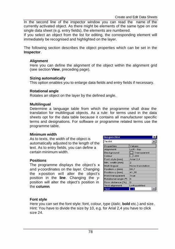
Create and Edit Data Sheets
78
In the second line of the inspector window you can read the name of the currently activated object. As there might be elements of the same type on one single data sheet (e.g. entry fields), the elements are numbered. If you select an object from the list for editing, the corresponding element will immediately be recognised and highlighted on the layer. The following section describes the object properties which can be set in the Inspector.
Alignment Here you can define the alignment of the object within the alignment grid (see section View, preceding page). Sizing automatically This option enables you to enlarge data fields and entry fields if necessary. Rotational angle Rotates an object on the layer by the defined angle. Multilingual Determine a language table from which the programme shall draw the translation for multilingual objects. As a rule: for terms used in the data sheets opt for the data table because it contains all manufacturer specific terms and designations. For software or programme related terms use the programme table. Minimum width As to texts, the width of the object is automatically adjusted to the length of the text. As to entry fields, you can define a certain minimum width. Positions The programme displays the object’s x- and y-coordinates on the layer. Changing the x-position wi ll alter the object’s position in the line. Changing the y-position will alter the object’s position in the column. Font style Here you can set the font style: font, colour, type (italic, bold etc.) and size. Hint: You have to divide the size by 10, e.g. for Arial 2,4 you have to click size 24.
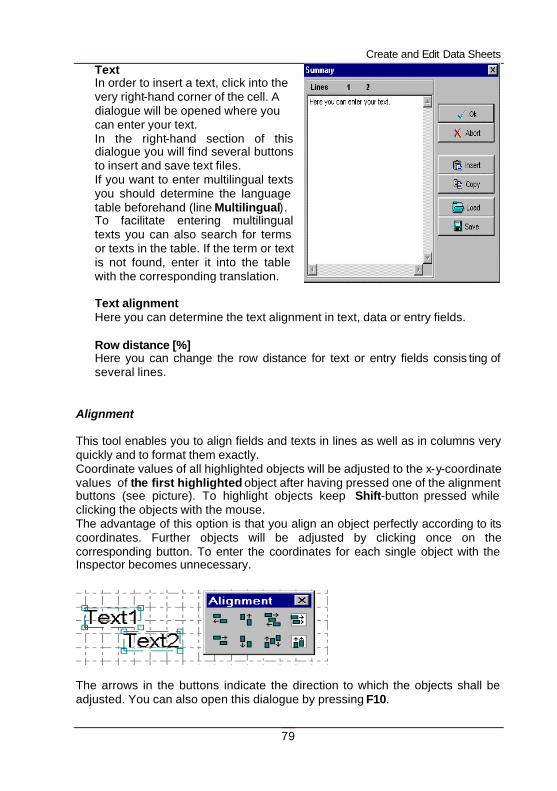
Create and Edit Data Sheets
79
Text In order to insert a text, click into the very right-hand corner of the cell. A dialogue will be opened where you can enter your text. In the right-hand section of this dialogue you will find several buttons to insert and save text files. If you want to enter multilingual texts you should determine the language table beforehand (line Multilingual). To facilitate entering multilingual texts you can also search for terms or texts in the table. If the term or text is not found, enter it into the table with the corresponding translation. Text alignment Here you can determine the text alignment in text, data or entry fields. Row distance [%] Here you can change the row distance for text or entry fields consis ting of several lines.
Alignment This tool enables you to align fields and texts in lines as well as in columns very quickly and to format them exactly. Coordinate values of all highlighted objects will be adjusted to the x-y-coordinate values of the first highlighted object after having pressed one of the alignment buttons (see picture). To highlight objects keep Shift-button pressed while clicking the objects with the mouse. The advantage of this option is that you align an object perfectly according to its coordinates. Further objects will be adjusted by clicking once on the corresponding button. To enter the coordinates for each single object with the Inspector becomes unnecessary.
The arrows in the buttons indicate the direction to which the objects shall be adjusted. You can also open this dialogue by pressing F10.
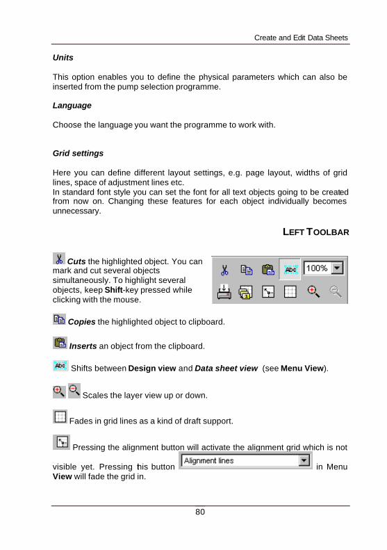
Create and Edit Data Sheets
80
Units This option enables you to define the physical parameters which can also be inserted from the pump selection programme. Language Choose the language you want the programme to work with. Grid settings Here you can define different layout settings, e.g. page layout, widths of grid lines, space of adjustment lines etc. In standard font style you can set the font for all text objects going to be created from now on. Changing these features for each object individually becomes unnecessary.
LEFT TOOLBAR
Cuts the highlighted object. You can mark and cut several objects simultaneously. To highlight several objects, keep Shift-key pressed while clicking with the mouse.
Copies the highlighted object to clipboard.
Inserts an object from the clipboard.
Shifts between Design view and Data sheet view (see Menu View).
Scales the layer view up or down.
Fades in grid lines as a kind of draft support.
Pressing the alignment button will activate the alignment grid which is not
visible yet. Pressing this button in Menu View will fade the grid in.
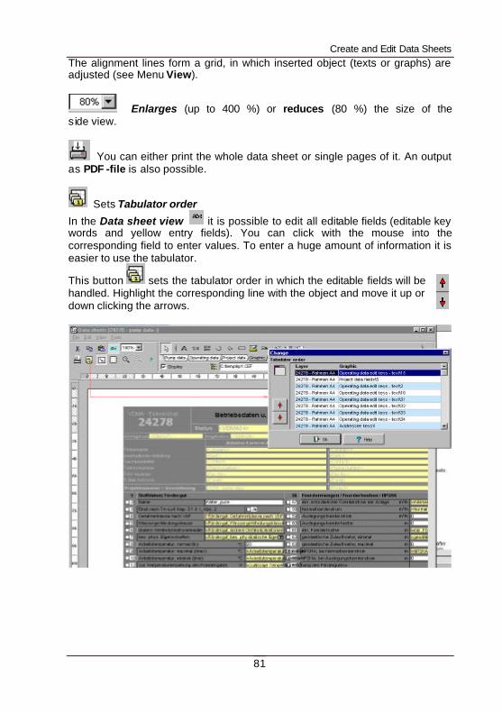
Create and Edit Data Sheets
81
The alignment lines form a grid, in which inserted object (texts or graphs) are adjusted (see Menu View).
Enlarges (up to 400 %) or reduces (80 %) the size of the s ide view.
You can either print the whole data sheet or single pages of it. An output as PDF -file is also possible.
Sets Tabulator order
In the Data sheet view it is possible to edit all editable fields (editable key words and yellow entry fields). You can click with the mouse into the corresponding field to enter values. To enter a huge amount of information it is easier to use the tabulator.
This button sets the tabulator order in which the editable fields will be handled. Highlight the corresponding line with the object and move it up or down clicking the arrows.
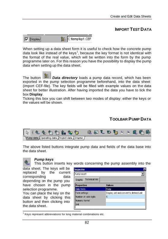
Create and Edit Data Sheets
82
IMPORT TEST DATA
When setting up a data sheet form it is useful to check how the concrete pump data look like instead of the keys1, because the key format is not identical with the format of the real value, which will be written into the form by the pump programme later on. For this reason you have the possibility to display the pump data when setting up the data sheet.
The button Data directory loads a pump data record, which has been exported in the pump selection programme beforehand, into the data sheet (import CEF-file). The key fields will be filled with example values on the data sheet for better illustration. After having imported the data you have to tick the box Display. Ticking this box you can shift between two modes of display: either the keys or the values will be shown.
TOOLBAR PUMP DATA
The above listed buttons integrate pump data and fields of the data base into the data sheet.
Pump keys This button inserts key words concerning the pump assembly into the
data sheet. The keys will be replaced by the current corresponding data depending on the pump you have chosen in the pump selection programme. You can place the key on the data sheet by clicking this button and then clicking into the data sheet. 1 Keys represent abbreviations for long material combinations etc.
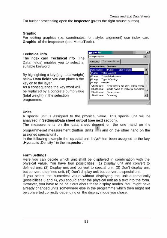
Create and Edit Data Sheets
83
For further processing open the Inspector (press the right mouse button). Graphic For editing graphics (i.e. coordinates, font style, alignment) use index card Graphic of the Inspector (see Menu Tools). Technical info The index card Technical info (line Data fields) enables you to select a suitable keyword. By highlighting a key (e.g. total weight) below Data fields you can place a the key on to the layer. As a consequence the key word will be replaced by a concrete pump value (total weight) in the selection programme. Units A special unit is assigned to the physical value. This special unit will be analysed in Settings/Data sheet output (see next section). The measurements on the data sheet depend on the one hand on the
programme-set measurement (button Units ) and on the other hand on the assigned special unit . In the following example the special unit ltn/yd³ has been assigned to the key „Hydraulic ;Density “ in the Inspector. Form Settings Here you can decide which unit shall be displayed in combination with the physical value. You have four possibilities: (1) Display unit and convert to defined unit, (2) Display unit and convert to special unit, (3) Don’t display unit but convert to defined unit, (4) Don’t display unit but convert to special unit. If you select the numerical value without displaying the unit automatically (possibilities 3 and 4), you should enter the physical unit as a text into the form. However, you have to be cautious about these display modes. You might have already changed units somewhere else in the programme which then might not be converted correctly depending on the display mode you chose.
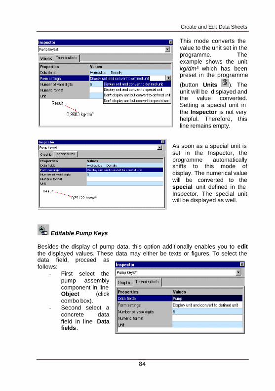
Create and Edit Data Sheets
84
This mode converts the value to the unit set in the programme. The example shows the unit kg/dm³ which has been preset in the programme
(button Units ). The unit will be displayed and the value converted. Setting a special unit in the Inspector is not very helpful. Therefore, this line remains empty.
As soon as a special unit is set in the Inspector, the programme automatically shifts to this mode of display. The numerical value will be converted to the special unit defined in the Inspector. The special unit will be displayed as well.
Editable Pump Keys Besides the display of pump data, this option additionally enables you to edit the displayed values. These data may either be texts or figures. To select the data field, proceed as follows:
- First select the pump assembly component in line Object (click combo box).
- Second select a concrete data field in line Data fields.
Create and Edit Data Sheets
85
Hint: As the possibility to edit pump data depends on the user group, it is up to the pump manufacturer to release certain data for certain users. It is set in the data base who may change data. Editable fields on the data sheet are yellow. The lines Units and Form Settings have already been explained on the preceding page. You can determine the format of the displayed figures. The line Floating number digit shows, how many positions after the decimal point shall be rounded. This might be useful when converting values to other units or when calculating fields. After the conversion the value often has several positions after the decimal point and should therefore be rounded. Explication: Determine the number of positions that shall be rounded. Example: If you enter in line Floating number digit „3“ and „43,19“ as a concrete value, the figure will be reduced to three positions: 43,2. If you enter instead a value of 5434892 it will be rounded in the following way (Floating number digit „3“): 5430000. Only the first three figures will be shown and the remaining figures will be turned 0, positions after the decimal point will not be displayed. As an alternative to line Floating number digit, you can enter in line Numeric format a special format for the figures . Formatting specification 0 Wild card for a figure. In case the value that shall be formatted contains
at this position a figure having '0' in the format sequence, the figure will be copied to the output sequence.
# Wild card for a figure. In case the value that shall be formatted contains
at this position a figure having '#' in the format sequence, the figure will be copied to the output sequence. Otherwise, no character will be saved in the output string at this position.
. decimal separator
, thousand separator
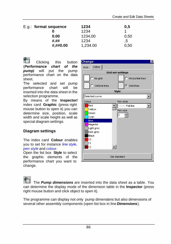
Create and Edit Data Sheets
86
E.g.: format sequence 1234 0,5
0 1234 1 0.00 1234,00 0,50 #.## 1234 ,5 #,##0.00 1,234.00 0,50
Clicking this button (Performance chart of the pump) will put the pump performance chart on the data sheet. The selected and set pump performance chart will be inserted into the data sheet in the selection programme. By means of the Inspector/ index card Graphic (press right mouse button to open it) you can determine size, position, scale width and scale height as well as special diagram settings. Diagram settings The index card Colour enables you to set for instance line style, pen style and colour. Open the list box Style to select the graphic elements of the performance chart you want to change.
The Pump dimensions are inserted into the data sheet as a table. You can determine the display mode of the dimension table in the Inspector (press right mouse button and click object to open it). The programme can display not only pump dimensions but also dimensions of several other assembly components (open list box in line Dimensions).
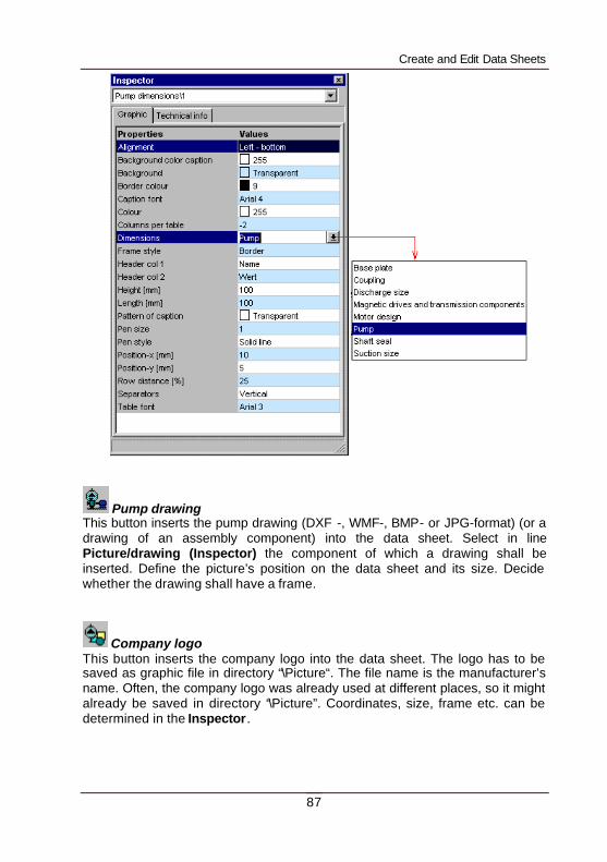
Create and Edit Data Sheets
87
Pump drawing This button inserts the pump drawing (DXF -, WMF-, BMP- or JPG-format) (or a drawing of an assembly component) into the data sheet. Select in line Picture/drawing (Inspector) the component of which a drawing shall be inserted. Define the picture’s position on the data sheet and its size. Decide whether the drawing shall have a frame.
Company logo This button inserts the company logo into the data sheet. The logo has to be saved as graphic file in directory “\Picture“. The file name is the manufacturer’s name. Often, the company logo was already used at different places, so it might already be saved in directory “\Picture”. Coordinates, size, frame etc. can be determined in the Inspector.
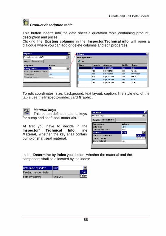
Create and Edit Data Sheets
88
Product description table This button inserts into the data sheet a quotation table containing product description and prices. Clicking line Existing columns in the Inspector/Technical info will open a dialogue where you can add or delete columns and edit properties.
To edit coordinates, size, background, text layout, caption, line style etc. of the table use the Inspector/index card Graphic.
Material keys This button defines material keys
for pump and shaft seal materials. At first you have to decide in the Inspector/ Technical Info, line Material, whether the key shall contain pump or shaft seal material. In line Determine by index you decide, whether the material and the component shall be allocated by the index:
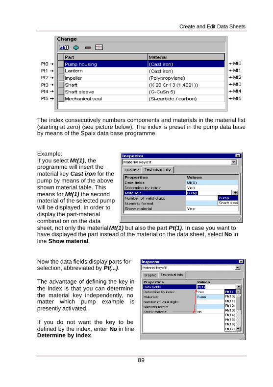
Create and Edit Data Sheets
89
The index consecutively numbers components and materials in the material list (starting at zero) (see picture below). The index is preset in the pump data base by means of the Spaix data base programme. Example: If you select Mt(1), the programme will insert the material key Cast iron for the pump by means of the above shown material table. This means for Mt(1) the second material of the selected pump will be displayed. In order to display the part-material combination on the data sheet, not only the material Mt(1) but also the part Pt(1). In case you want to have displayed the part instead of the material on the data sheet, select No in line Show material. Now the data fields display parts for selection, abbreviated by Pt(...). The advantage of defining the key in the index is that you can determine the material key independently, no matter which pump example is presently activated. If you do not want the key to be defined by the index, enter No in line Determine by index.
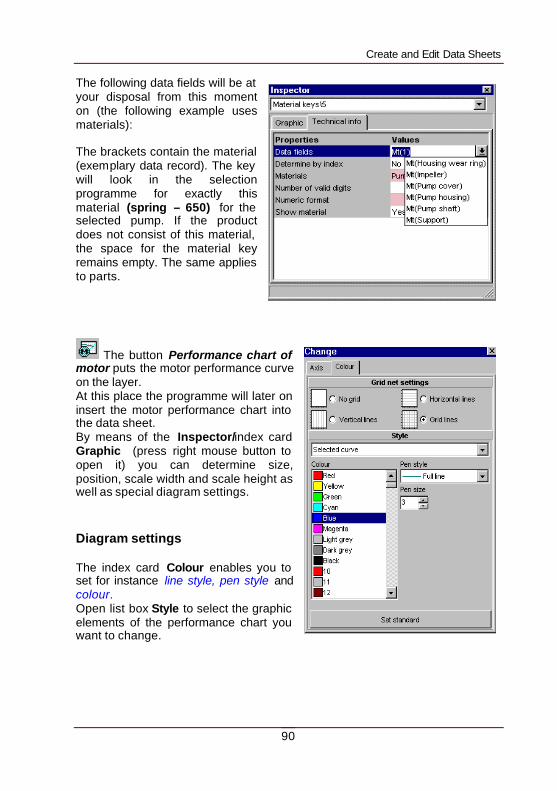
Create and Edit Data Sheets
90
The following data fields will be at your disposal from this moment on (the following example uses materials): The brackets contain the material (exemplary data record). The key will look in the selection programme for exactly this material (spring – 650) for the selected pump. If the product does not consist of this material, the space for the material key remains empty. The same applies to parts.
The button Performance chart of motor puts the motor performance curve on the layer. At this place the programme will later on insert the motor performance chart into the data sheet. By means of the Inspector/index card Graphic (press right mouse button to open it) you can determine size, position, scale width and scale height as well as special diagram settings. Diagram settings The index card Colour enables you to set for instance line style, pen style and colour. Open list box Style to select the graphic elements of the performance chart you want to change.
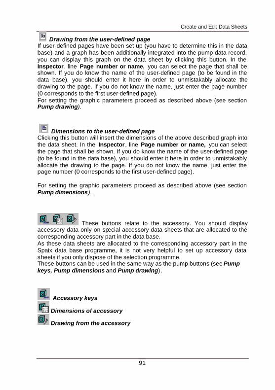
Create and Edit Data Sheets
91
Drawing from the user-defined page If user-defined pages have been set up (you have to determine this in the data base) and a graph has been additionally integrated into the pump data record, you can display this graph on the data sheet by clicking this button. In the Inspector, line Page number or name, you can select the page that shall be shown. If you do know the name of the user-defined page (to be found in the data base), you should enter it here in order to unmistakably allocate the drawing to the page. If you do not know the name, just enter the page number (0 corresponds to the first user-defined page). For setting the graphic parameters proceed as described above (see section Pump drawing).
Dimensions to the user-defined page Clicking this button will insert the dimensions of the above described graph into the data sheet. In the Inspector, line Page number or name, you can select the page that shall be shown. If you do know the name of the user-defined page (to be found in the data base), you should enter it here in order to unmistakably allocate the drawing to the page. If you do not know the name, just enter the page number (0 corresponds to the first user-defined page). For setting the graphic parameters proceed as described above (see section Pump dimensions).
These buttons relate to the accessory. You should display accessory data only on special accessory data sheets that are allocated to the corresponding accessory part in the data base. As these data sheets are allocated to the corresponding accessory part in the Spaix data base programme, it is not very helpful to set up accessory data sheets if you only dispose of the selection programme. These buttons can be used in the same way as the pump buttons (see Pump keys, Pump dimensions and Pump drawing).
Accessory keys
Dimensions of accessory
Drawing from the accessory
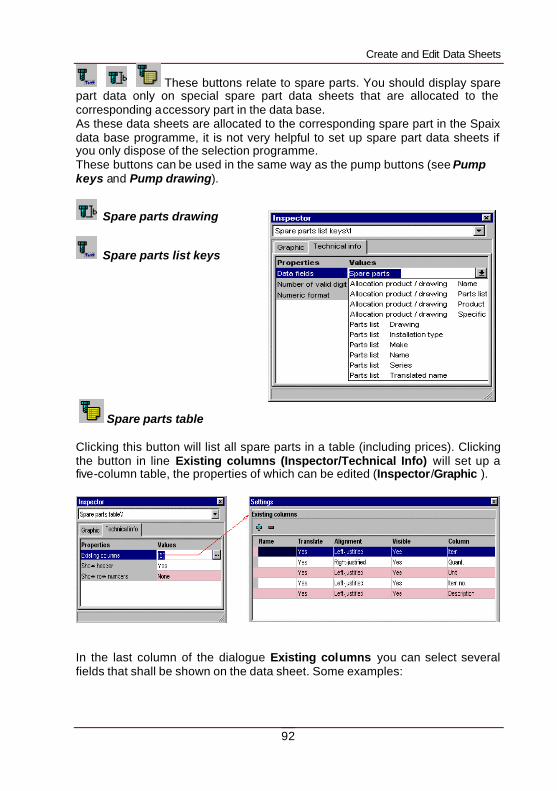
Create and Edit Data Sheets
92
These buttons relate to spare parts. You should display spare part data only on special spare part data sheets that are allocated to the corresponding accessory part in the data base. As these data sheets are allocated to the corresponding spare part in the Spaix data base programme, it is not very helpful to set up spare part data sheets if you only dispose of the selection programme. These buttons can be used in the same way as the pump buttons (see Pump keys and Pump drawing).
Spare parts drawing
Spare parts list keys
Spare parts table Clicking this button will list all spare parts in a table (including prices). Clicking the button in line Existing columns (Inspector/Technical Info) will set up a five-column table, the properties of which can be edited (Inspector/Graphic ).
In the last column of the dialogue Existing columns you can select several fields that shall be shown on the data sheet. Some examples:
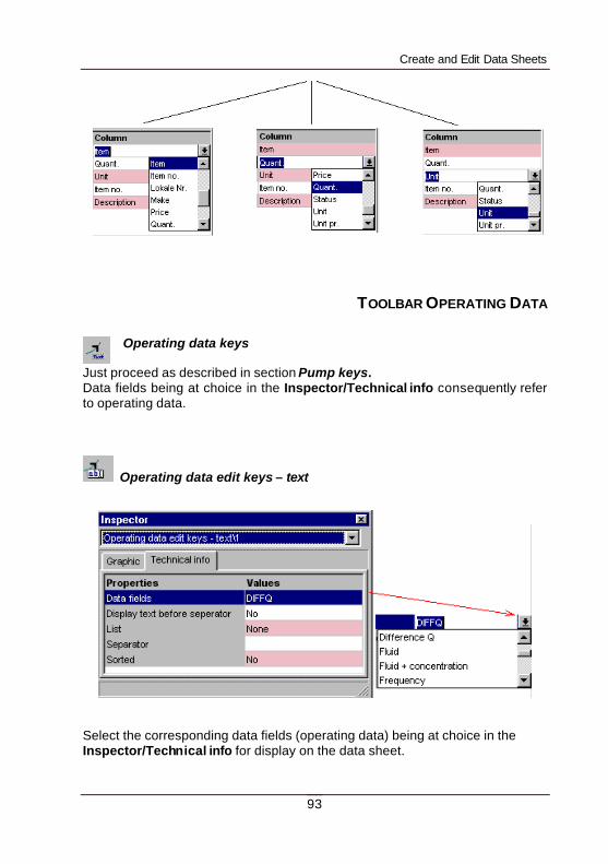
Create and Edit Data Sheets
93
TOOLBAR OPERATING DATA Operating data keys
Just proceed as described in section Pump keys. Data fields being at choice in the Inspector/Technical info consequently refer to operating data.
Operating data edit keys – text
Select the corresponding data fields (operating data) being at choice in the Inspector/Technical info for display on the data sheet.
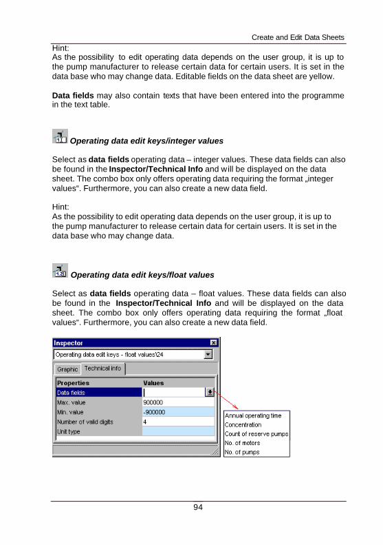
Create and Edit Data Sheets
94
Hint: As the possibility to edit operating data depends on the user group, it is up to the pump manufacturer to release certain data for certain users. It is set in the data base who may change data. Editable fields on the data sheet are yellow. Data fields may also contain texts that have been entered into the programme in the text table.
Operating data edit keys/integer values Select as data fields operating data – integer values. These data fields can also be found in the Inspector/Technical Info and will be displayed on the data sheet. The combo box only offers operating data requiring the format „integer values“. Furthermore, you can also create a new data field. Hint: As the possibility to edit operating data depends on the user group, it is up to the pump manufacturer to release certain data for certain users. It is set in the data base who may change data.
Operating data edit keys/float values Select as data fields operating data – float values. These data fields can also be found in the Inspector/Technical Info and will be displayed on the data sheet. The combo box only offers operating data requiring the format „float values“. Furthermore, you can also create a new data field.
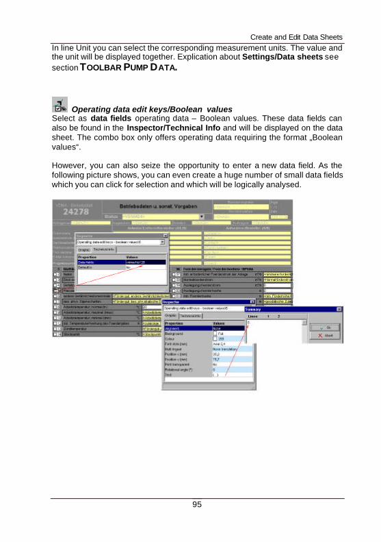
Create and Edit Data Sheets
95
In line Unit you can select the corresponding measurement units. The value and the unit will be displayed together. Explication about Settings/Data sheets see section TOOLBAR PUMP DATA.
Operating data edit keys/Boolean values Select as data fields operating data – Boolean values. These data fields can also be found in the Inspector/Technical Info and will be displayed on the data sheet. The combo box only offers operating data requiring the format „Boolean values“. However, you can also seize the opportunity to enter a new data field. As the following picture shows, you can even create a huge number of small data fields which you can click for selection and which will be logically analysed.
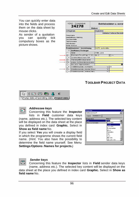
Create and Edit Data Sheets
96
You can quickly enter data into the fields and process them on the data sheet by mouse clicks. As sender of a quotation you can quickly tick compulsory boxes as the picture shows.
TOOLBAR PROJECT DATA
Addressee keys Concerning this feature the Inspector lists in Field customer data keys
(name, address etc.). The selected key content will be displayed on the data sheet at the place you defined in index card Graphic. Select in Show as field name No. If you select Yes you will create a display field in which the programme shows the current field name. (Hint: You also have the possibility to determine the field name yourself. See Menu Settings/Options /Names for projects.)
Sender keys Concerning this feature the Inspector lists in Field sender data keys (name, address etc.). The selected key content will be displayed on the
data sheet at the place you defined in index card Graphic. Select in Show as field name No.
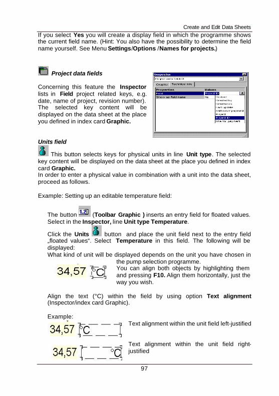
Create and Edit Data Sheets
97
If you select Yes you will create a display field in which the programme shows the current field name. (Hint: You also have the possibility to determine the field name yourself. See Menu Settings/Options /Names for projects.)
Project data fields Concerning this feature the Inspector lists in Field project related keys, e.g. date, name of project, revision number). The selected key content will be displayed on the data sheet at the place you defined in index card Graphic. Units field
This button selects keys for physical units in line Unit type. The selected key content will be displayed on the data sheet at the place you defined in index card Graphic. In order to enter a physical value in combination with a unit into the data sheet, proceed as follows. Example: Setting up an editable temperature field:
The button (Toolbar Graphic ) inserts an entry field for floated values. Select in the Inspector, line Unit type Temperature.
Click the Units button and place the unit field next to the entry field „floated values“. Select Temperature in this field. The following will be displayed: What kind of unit will be displayed depends on the unit you have chosen in
the pump selection programme. You can align both objects by highlighting them and pressing F10. Align them horizontally, just the way you wish.
Align the text (°C) within the field by using option Text alignment (Inspector/index card Graphic). Example:
Text alignment within the unit field left-justified Text alignment within the unit field right-justified
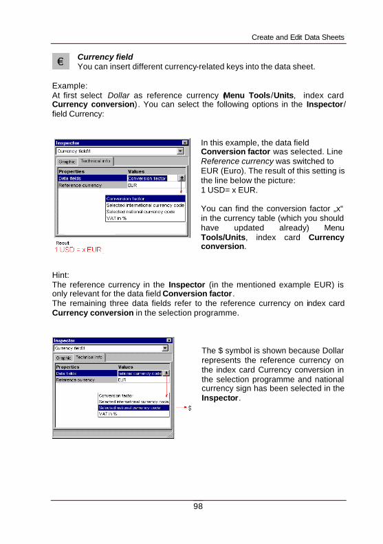
Create and Edit Data Sheets
98
Currency field You can insert different currency-related keys into the data sheet.
Example: At first select Dollar as reference currency (Menu Tools/Units, index card Currency conversion). You can select the following options in the Inspector/ field Currency:
In this example, the data field Conversion factor was selected. Line Reference currency was switched to EUR (Euro). The result of this setting is the line below the picture: 1 USD= x EUR. You can find the conversion factor „x“ in the currency table (which you should have updated already) Menu Tools/Units, index card Currency conversion.
Hint: The reference currency in the Inspector (in the mentioned example EUR) is only relevant for the data field Conversion factor. The remaining three data fields refer to the reference currency on index card Currency conversion in the selection programme.
The $ symbol is shown because Dollar represents the reference currency on the index card Currency conversion in the selection programme and national currency sign has been selected in the Inspector.
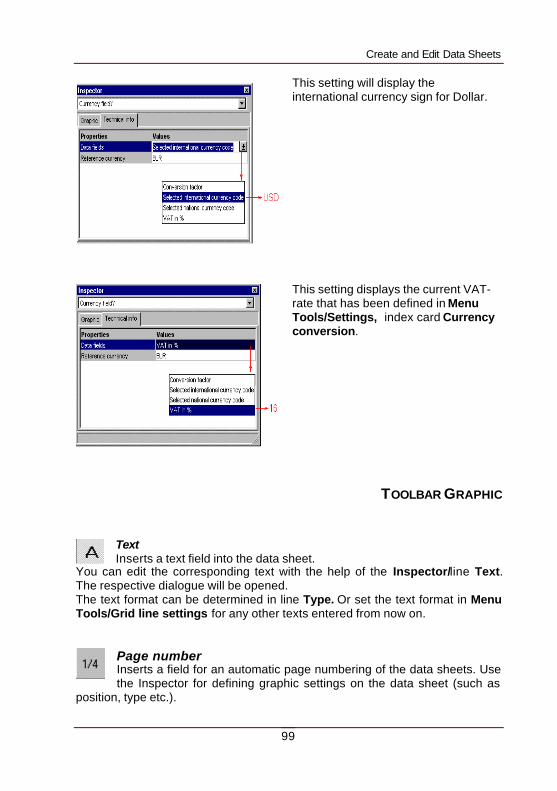
Create and Edit Data Sheets
99
This setting will display the international currency sign for Dollar.
This setting displays the current VAT-rate that has been defined in Menu Tools/Settings, index card Currency conversion.
TOOLBAR GRAPHIC
Text Inserts a text field into the data sheet.
You can edit the corresponding text with the help of the Inspector/line Text. The respective dialogue will be opened. The text format can be determined in line Type. Or set the text format in Menu Tools/Grid line settings for any other texts entered from now on.
Page number Inserts a field for an automatic page numbering of the data sheets. Use the Inspector for defining graphic settings on the data sheet (such as
position, type etc.).
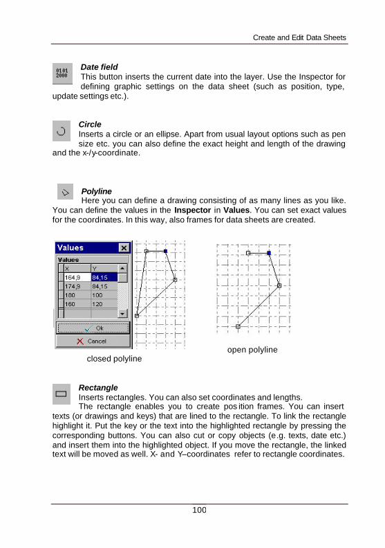
Create and Edit Data Sheets
100
Date field This button inserts the current date into the layer. Use the Inspector for defining graphic settings on the data sheet (such as position, type,
update settings etc.).
Circle Inserts a circle or an ellipse. Apart from usual layout options such as pen size etc. you can also define the exact height and length of the drawing
and the x-/y-coordinate.
Polyline Here you can define a drawing consisting of as many lines as you like.
You can define the values in the Inspector in Values. You can set exact values for the coordinates. In this way, also frames for data sheets are created.
open polyline
closed polyline
Rectangle Inserts rectangles. You can also set coordinates and lengths. The rectangle enables you to create pos ition frames. You can insert
texts (or drawings and keys) that are lined to the rectangle. To link the rectangle highlight it. Put the key or the text into the highlighted rectangle by pressing the corresponding buttons. You can also cut or copy objects (e.g. texts, date etc.) and insert them into the highlighted object. If you move the rectangle, the linked text will be moved as well. X- and Y–coordinates refer to rectangle coordinates.
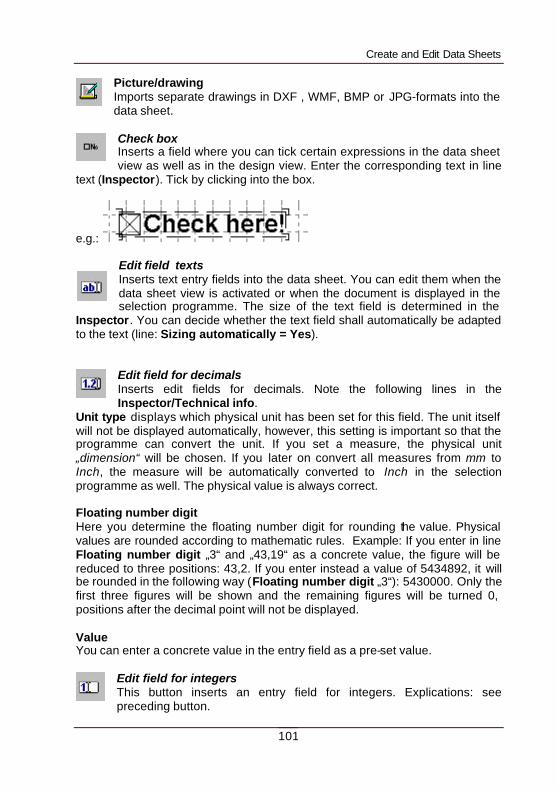
Create and Edit Data Sheets
101
Picture/drawing Imports separate drawings in DXF , WMF, BMP or JPG-formats into the data sheet.
Check box Inserts a field where you can tick certain expressions in the data sheet view as well as in the design view. Enter the corresponding text in line
text (Inspector). Tick by clicking into the box.
e.g.:
Edit field texts Inserts text entry fields into the data sheet. You can edit them when the data sheet view is activated or when the document is displayed in the selection programme. The size of the text field is determined in the
Inspector. You can decide whether the text field shall automatically be adapted to the text (line: Sizing automatically = Yes).
Edit field for decimals Inserts edit fields for decimals. Note the following lines in the Inspector/Technical info.
Unit type displays which physical unit has been set for this field. The unit itself will not be displayed automatically, however, this setting is important so that the programme can convert the unit. If you set a measure, the physical unit „dimension“ will be chosen. If you later on convert all measures from mm to Inch, the measure will be automatically converted to Inch in the selection programme as well. The physical value is always correct. Floating number digit Here you determine the floating number digit for rounding the value. Physical values are rounded according to mathematic rules. Example: If you enter in line Floating number digit „3“ and „43,19“ as a concrete value, the figure will be reduced to three positions: 43,2. If you enter instead a value of 5434892, it will be rounded in the following way (Floating number digit „3“): 5430000. Only the first three figures will be shown and the remaining figures will be turned 0, positions after the decimal point will not be displayed. Value You can enter a concrete value in the entry field as a pre-set value.
Edit field for integers This button inserts an entry field for integers. Explications: see preceding button.
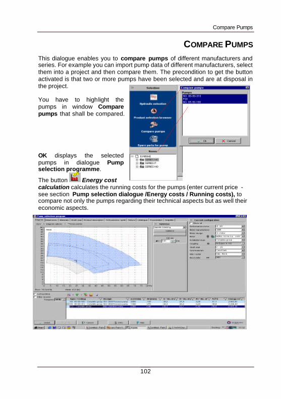
Compare Pumps
102
COMPARE PUMPS This dialogue enables you to compare pumps of different manufacturers and series. For example you can import pump data of different manufacturers, select them into a project and then compare them. The precondition to get the button activated is that two or more pumps have been selected and are at disposal in the project. You have to highlight the pumps in window Compare pumps that shall be compared. OK displays the selected pumps in dialogue Pump selection programme.
The button Energy cost calculation calculates the running costs for the pumps (enter current price - see section Pump selection dialogue /Energy costs / Running costs), to compare not only the pumps regarding their technical aspects but as well their economic aspects.
Index
103
INDEX accessory 17, 27 add 10, 14, 15, 17, 20, 24, 25 add accessory 17 area of application 7, 28, 30, 31, 32, 34 base plate 7, 38, 40 BEP 29 BMP 8 calculation 7, 8, 30, 36 catalogue 8, 15, 24, 26 catalogue administration 24 Catalogue Exchange-Format 24 CEF 8, 12, 21, 24, 26 CEF-file 21, 24 clipboard 12 compare 7, 11, 36 concentration 25, 37 configuration 7, 32, 33, 34, 38 copyright 5, 6 coupling 7, 24, 38, 40 currency conversion 19 customer data 15 data base 9, 10, 14, 16, 20, 24, 28, 31, 32, 33, 38, 39, 40 data directory 10, 18, 21 data exchange 8, 12, 13, 21 data exchange format 12, 13 data sheets 7, 8, 15, 16, 21, 23, 30 data update 26 delete 16, 20, 24, 25, 28, 35 density 25, 31, 37 dimensions 7, 16, 38, 40 directories 10, 18 directory 9, 10, 12, 18, 21, 24 discount 22 drawing 7, 8, 15, 21, 34 drawings 6, 7, 8, 24 duty chart 28, 32, 38 duty chart view 28, 32 duty point 7, 28, 30, 32, 34, 36 DXF 8 edit 11, 14, 16, 36 e-mail 8, 10, 13, 15, 21, 26, 27 energy cost calculation 36 energy costs 36
export 8, 13, 21, 23 filter 34, 35 flow 29, 30, 32, 36 fluids 25, 28, 31, 37 frequency 28, 33 friction loss calculation program 7, 25, 30 group 15 head 29, 30, 32 hydraulic 7, 11, 16, 22, 28, 29, 31, 32, 34 hydraulic selection 7, 11, 22, 28, 29, 31, 32, 34 impeller 7, 38 impeller trimming 7 import 12, 24, 26 import project data 12 INI-files 10 install license file 10, 18 installation 7, 9, 10, 26, 38, 39, 40 interfaces 8, 12, 13 JPG 8 Keys 82 language 18, 20, 23 languages 20, 23 main item 14 manufacturer 7, 8, 16, 18, 24, 28, 30, 33, 34, 38, 39, 40 MAPI 21 materials 7 motor 7, 34, 38, 39, 40 Newtonian fluids 7, 25 NPSH 30 numbering 16 open project 12 operating data 28 optimum 29 option 13, 17, 18, 21, 22, 23, 24, 26 parts list 8 performance curve 6, 7, 8, 21, 25, 28, 29, 31, 33, 38 prices 6, 19, 27 print 23 product selection browser 14
Index
104
product-related selection 7 programme directory 10 programme update 26 project data 12, 27 project data base 12 project directory 10, 12, 18 project management 8, 14, 27 pump performance curve 7, 36 pump selection 7, 9, 10, 21, 27, 30, 32 pump selection browser 33, 34 pump selection program 7, 10 ratings of fluids 25, 37 round 19 running costs 36 select item 14, 17 series 7, 22, 24, 28, 32, 33, 34 series operation 7 settings 7, 10, 11, 16, 18, 34, 36
shaft power 7 shaft seal 7, 24, 38 single pump 7 sort 35 Spaix PipeCalc 7, 30 Spaix-Online 27 speed 7, 38 standard data sheet 7, 8 temperature 30, 31, 37 thermometer 31 throttling 7 units 19 vane angle 7 vapour pressure 25, 37 VDMA-format 24 viscosity 25, 31, 37 WMF 8 XML 8