manufacturing of a heterogeneous flywheel on a lens apparatus · the materials selected are...
TRANSCRIPT

Manufacturing of a Heterogeneous Flywheel on a LENS Apparatus
Stephane Morvan [email protected]
Georges M. Fadel [email protected]
Dept. of Mechanical Engineering College of Engineering and Sciences
Clemson, SC 29634-0921
James Love [email protected]
Dave Keicher [email protected]
Optomec Inc. 3911 Singer Blvd, NE
Albuquerque, NM 87120 Abstract
The design of a 1D gradient component satisfying a particular set of constraints is extended to its manufacturing on a multi-material capable apparatus. The geometry and composition of this flywheel were designed to meet a bi-objective optimum featuring maximum kinetic energy storage and minimal maximum von-Mises stress along its radius. The efforts expanded during the transformation of this design from a computer abstraction into a tangible object are presented. The process-planning step of the manufacturing of this heterogeneous solid, which was dependent on the specifics of a LENS-based Apparatus, required a different approach than that of traditional solids, and proved critical during fabrication.
Introduction
Recent advances (Swann T.A., Keicher D.M. et al. 1998) in the direct deposition of metals have enabled the manufacture of gradient structures and functional materials to provide exciting new alternatives for the design of components. Akin to composites and carbon fibers, these new processes allow the strength and other functional features of a particular material to be used exactly where they are needed within that component, and evade the tradeoffs that are normally made when a particular material is chosen. For example, in the design of a turbine blade, one might find the limited mechanical properties of a ceramic to be problematic in areas where mechanical strength would prevail over thermal properties. Conversely, in that same blade, the thermal properties of a titanium alloy might limit its usefulness in areas exposed to very high temperatures. Using a carefully designed mix of both ceramics and titanium throughout the blade may provide an adequate solution to this problem should the two materials coexist. (König and Fadel, 1999)
When a part is designed from its inception as being composed of multiple materials, the repartition of the material within this solid can be selected using optimization tools such as genetic algorithms ((Goldberg, 1989), (Hajela, 1992), (König, 1999), (Huang and Fadel 1999)). Most optimization tools rely on a discretization of the geometric domain into smaller domains where the material composition can be changed. The difficulty in choosing a particular material distribution grows with the material space available for each subdomain.
From the optimization standpoint, every design variable input to an optimization problem seeks a best value for a mechanical or thermal property given a particular objective to attain (for example: smallest deformation and lightest structure.) The mapping between this property (mechanical or thermal) and a material composition is simplified to be of a linear nature: a part made from 50% Copper and 50% Steel has a strength that is in the same proportions than that of its composition, in that case 50% of Copper strength added to 50% of Steel strength.) Other mixing rules are currently under investigation to fully enable the resolution of the inverse problem (Huang, 2000), Grujicic et al., 2001.)
Heterogeneous Flywheel Optimization
A flywheel is a mechanical component that stores kinetic energy. The mass distribution of a flywheel around its axis of revolution impacts its capacity to store kinetic energy. A high-energy storage is
553
typically attained whenever the mass is distributed as far as possible, from the axis of revolution (e.g. on the circumference of the flywheel.) Huang (Huang and Fadel, 1999) proposed a novel approach to the design of a flywheel: essentially, since this is a solid of revolution, the problem is reduced to the design of its cross section. The geometry, along with the composition in a cross section is designed by blending two materials with opposed properties (high strength/low weight and low strength/high weight).
The design is therefore treated as an optimization problem; with the following objectives:
• Maximize kinetic energy stored, • Minimize maximal von-Mises equivalent stress,
The following constraints limit the design:
• Dimensional constraints (maximum height, internal and external radius.)
The composition is represented by way of the volume fractions of Material A with respect to Material B. The geometry and the composition are represented using parametric equations featuring Bezier blending functions:
∑=
⋅=n
i
nii uBzuz
0)()(
∑=
⋅=n
i
ni
ia uBu
a0
)()( νν
∑=
⋅=n
i
nii uBrur
0)()(
inini uu
ininuB −−⋅⋅−⋅
= )1()!(!
!)(
10 ≤≤ u
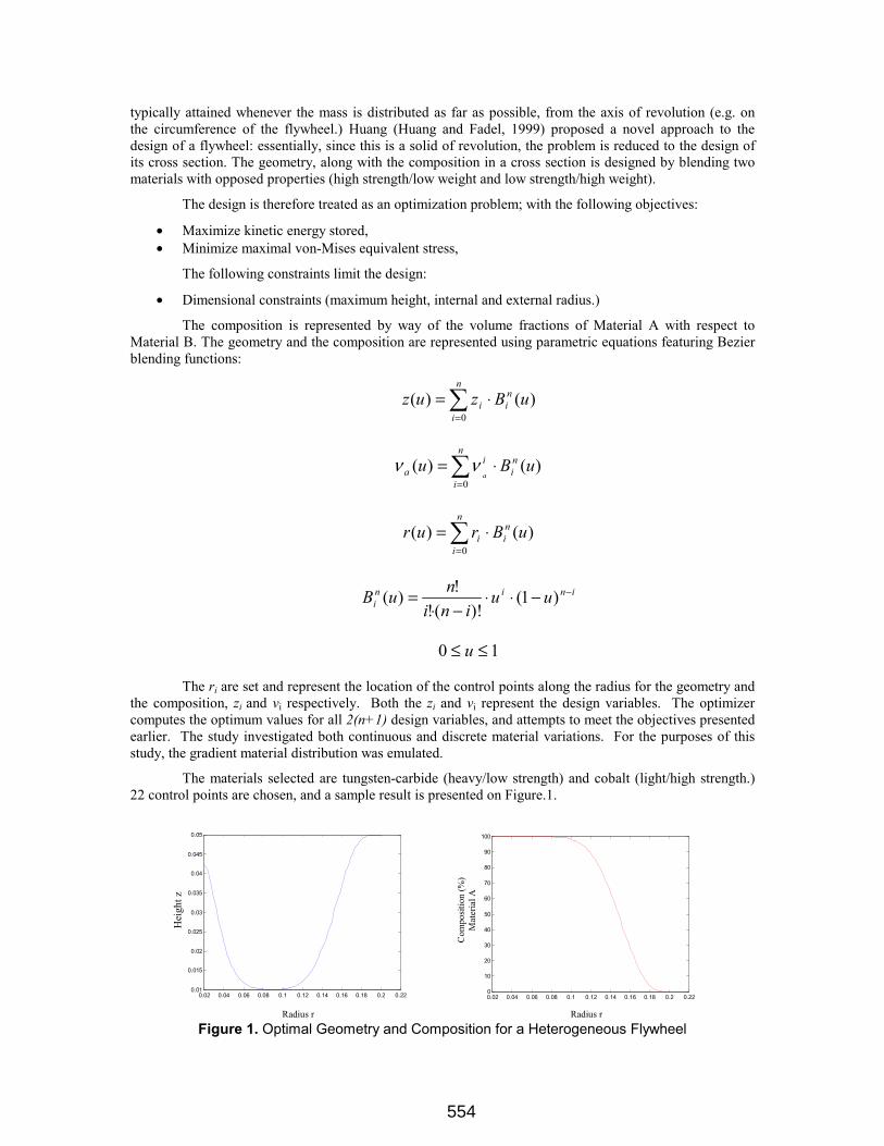
The ri are set and represent the location of the control points along the radius for the geometry and the composition, zi and νi respectively. Both the zi and νi represent the design variables. The optimizer computes the optimum values for all 2(n+1) design variables, and attempts to meet the objectives presented earlier. The study investigated both continuous and discrete material variations. For the purposes of this study, the gradient material distribution was emulated.
The materials selected are tungsten-carbide (heavy/low strength) and cobalt (light/high strength.) 22 control points are chosen, and a sample result is presented on Figure.1.
0.02 0.04 0.06 0.08 0.1 0.12 0.14 0.16 0.18 0.2 0.220.01
0.015
0.02
0.025
0.03
0.035
0.04
0.045
0.05
0.02 0.04 0.06 0.08 0.1 0.12 0.14 0.16 0.18 0.2 0.220
10
20
30
40
50
60
70
80
90
100
Radius r Radius r
Com
posit
ion
(%)
Mat
eria
l A
Hei
ght z
Figure 1. Optimal Geometry and Composition for a Heterogeneous Flywheel
554
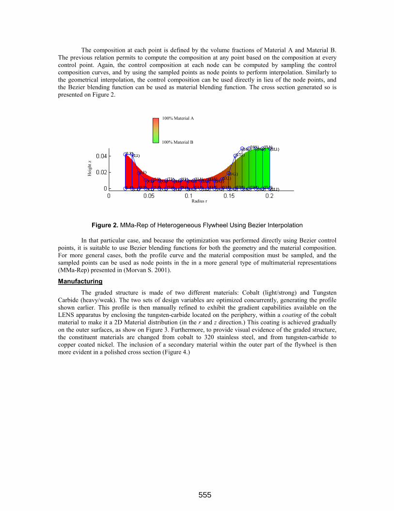
The composition at each point is defined by the volume fractions of Material A and Material B. The previous relation permits to compute the composition at any point based on the composition at every control point. Again, the control composition at each node can be computed by sampling the control composition curves, and by using the sampled points as node points to perform interpolation. Similarly to the geometrical interpolation, the control composition can be used directly in lieu of the node points, and the Bezier blending function can be used as material blending function. The cross section generated so is presented on Figure 2.
Radius r
Hei
ght z
100% Material A
100% Material B
Figure 2. MMa-Rep of Heterogeneous Flywheel Using Bezier Interpolation
In that particular case, and because the optimization was performed directly using Bezier control points, it is suitable to use Bezier blending functions for both the geometry and the material composition. For more general cases, both the profile curve and the material composition must be sampled, and the sampled points can be used as node points in the in a more general type of multimaterial representations (MMa-Rep) presented in (Morvan S. 2001).
Manufacturing
The graded structure is made of two different materials: Cobalt (light/strong) and Tungsten Carbide (heavy/weak). The two sets of design variables are optimized concurrently, generating the profile shown earlier. This profile is then manually refined to exhibit the gradient capabilities available on the LENS apparatus by enclosing the tungsten-carbide located on the periphery, within a coating of the cobalt material to make it a 2D Material distribution (in the r and z direction.) This coating is achieved gradually on the outer surfaces, as show on Figure 3. Furthermore, to provide visual evidence of the graded structure, the constituent materials are changed from cobalt to 320 stainless steel, and from tungsten-carbide to copper coated nickel. The inclusion of a secondary material within the outer part of the flywheel is then more evident in a polished cross section (Figure 4.)
555

Cobalt
Tungsten-Carbide
Top: Original Design Bottom: Modified Design
Figure 3. Original and Modified Flywheel Design
The polished cross section shows cavities (white spots) that result from the insufficient melting of the powder mix. Those cavities are grains of powder trapped in the molten material that were removed during the polishing of the cross section. This porosity can be controlled and practically eliminated if the system parameters (laser power, speed, powder size, powder massflow rate) are appropriately selected and modulated as a function of the material properties. Since the purpose of this work was to show feasibility, these issues were not stressed.
320 Stainless Steel Copper Coated Nickel
Figure 4. Cross Section of the Gradient Flywheel
Furthermore, from Figure 4 and Figure 5, it is observed that the geometrical accuracy is not adequate as most of the geometrical features are roughly approximated. However, on well calibrated machines, the geometrical accuracy is less of a problem, as can be seen (Figure 5.) This part shows excellent (and uniform) accuracy and improved surface finish when building is achieved on a well-configured LENS apparatus. The constant orientation hatch pattern and the single material greatly contribute to these improvements.
556

Figure 5. Exterior View of the Gradient Flywheel
The technology used for the control of the material composition does not allow alteration of the powder mix within a single laser stroke. Thus, for the deposition of a set material composition, the powder mix was altered ahead of the actual deposition phase. The time taken to alter the material composition at the nozzle is about 2 or 3 orders of magnitude of the time required to move the head of the apparatus to another location. Therefore the material composition is changed infrequently to minimize the performance hit on manufacturing time, and conversely, laser strokes of similar compositions are generated in sequence.
In its current form, the LENS manufacturing process is akin to a plotter capable of using a set of inks mixed upward from the pen. Thus, depositing the material is a combination of four basic operations, comparable to pen up, pen down, pen color and pen move operations:
• A pen up operation consists of shutting the laser off, • A pen down operation consists of turning the laser on, • A pen color operation consists of altering the material composition by modifying the powder mix, • A pen move operation consists of moving the laser to a new location.
Flywheel File Preparation
For single material parts, the traditional process planning stage of the LENS apparatus is essentially to use an .STL file representing the geometry, slice it using adaptive slicing, and convert the slice file in a set of instructions used to program the controlling apparatus (termed a .DMC file.) The heterogeneous nature of this flywheel does not permit its representation in the .STL format (it assumes single material,) therefore the conversion from .STL to slice file is not possible. The .DMC file is instead created directly from the representation presented earlier.
The selection of the hatching pattern is immediately resolved by observing that the constant composition paths are made of concentric rings.
Once the hatching space (0.015 in.) and layer thickness are selected (0.010 in.), the profile is sampled in both r and z direction for composition. The rings are then sorted by z-height, by composition and finally by decreasing radii. Thus, within a given slice, rings of similar composition are deposited at once, minimizing travel time of the head. A flowchart of the essential steps is presented on Figure 6.
557

Start Set r=rmin, z=0
Increment r: r=r+0.015
r > rmax?
Compute zmax: zmax=Z(r)
Initialize z: z=0
Compute c: c=C(r,z)
Increment z: z=z+0.010
Store new ring: (r, z, c)
z>zmax ?1
0
0
Sort rings
1
Write Instruction File
End
Figure 6. Flywheel File Preparation Flowchart
For rings of different composition, the effects of composition change are somewhat damped, since the transient states that incurred in the powder feeding apparatus are only between neighboring states and exclusively monotonic (e.g. the compositions vary from 10-90 to 15-85, to 20-80& in % volume fractions of 320 stainless steel and copper-coated nickel respectively.) A 20 ms wait was sufficient between adjustments to assume that a steady state was reached in the powder feeder. A first trial revealed that as the deposition head repeatedly waits for the powder feeder to reach a steady state at the same location, material was also being deposited at the latter, producing undesired ridges. The creation of the .DMC file was then modified to randomize the starting and ending angles used to create the rings, thus alleviating the possible buildup of material.
558
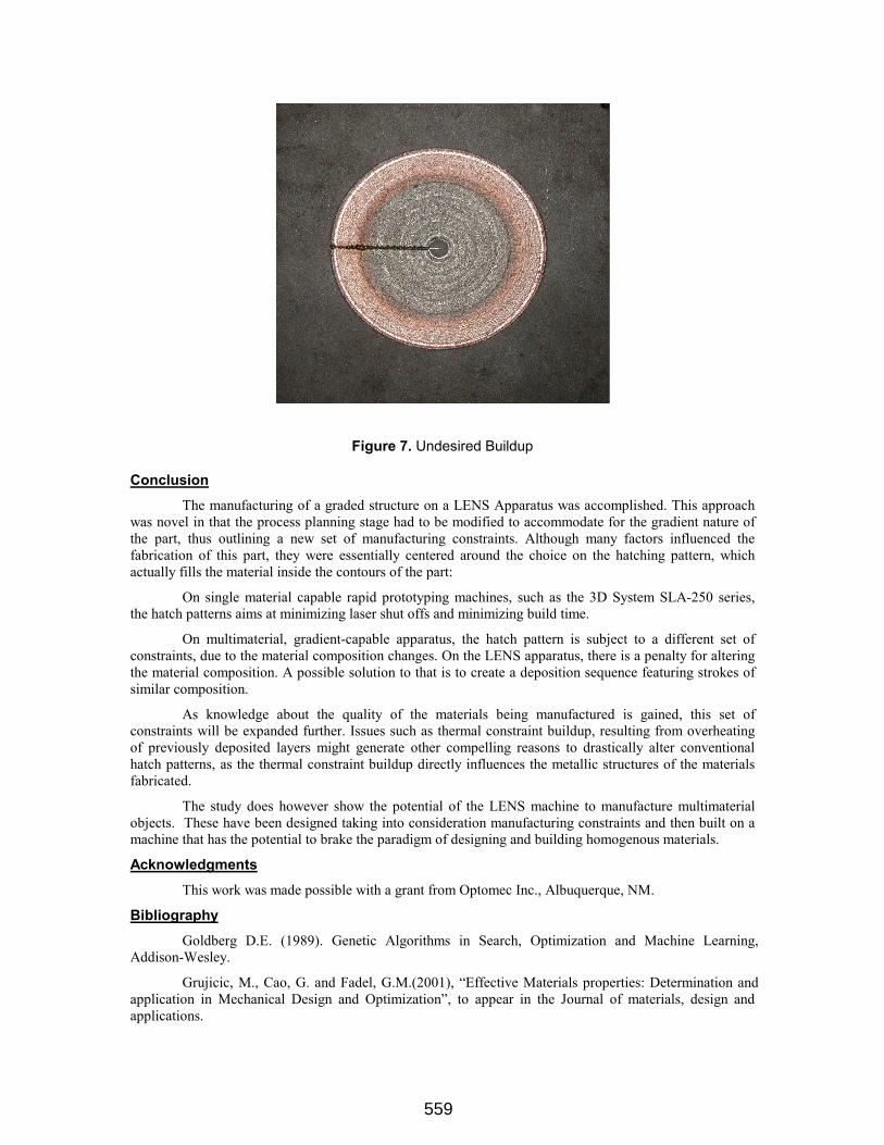
Figure 7. Undesired Buildup
Conclusion
The manufacturing of a graded structure on a LENS Apparatus was accomplished. This approach was novel in that the process planning stage had to be modified to accommodate for the gradient nature of the part, thus outlining a new set of manufacturing constraints. Although many factors influenced the fabrication of this part, they were essentially centered around the choice on the hatching pattern, which actually fills the material inside the contours of the part:
On single material capable rapid prototyping machines, such as the 3D System SLA-250 series, the hatch patterns aims at minimizing laser shut offs and minimizing build time.
On multimaterial, gradient-capable apparatus, the hatch pattern is subject to a different set of constraints, due to the material composition changes. On the LENS apparatus, there is a penalty for altering the material composition. A possible solution to that is to create a deposition sequence featuring strokes of similar composition.
As knowledge about the quality of the materials being manufactured is gained, this set of constraints will be expanded further. Issues such as thermal constraint buildup, resulting from overheating of previously deposited layers might generate other compelling reasons to drastically alter conventional hatch patterns, as the thermal constraint buildup directly influences the metallic structures of the materials fabricated.
The study does however show the potential of the LENS machine to manufacture multimaterial objects. These have been designed taking into consideration manufacturing constraints and then built on a machine that has the potential to brake the paradigm of designing and building homogenous materials.
Acknowledgments
This work was made possible with a grant from Optomec Inc., Albuquerque, NM.
Bibliography
Goldberg D.E. (1989). Genetic Algorithms in Search, Optimization and Machine Learning, Addison-Wesley.
Grujicic, M., Cao, G. and Fadel, G.M.(2001), “Effective Materials properties: Determination and application in Mechanical Design and Optimization”, to appear in the Journal of materials, design and applications.
559
Hajela P. (1992). Stochastic Search in Structural Optimization: Genetic Algorithms and Simulated Annealing. Progress in Astronautics and Aeronautics 150: 611-637.
Huang J. and Fadel G.M. (1999). Heterogeneous Flywheel Modeling & Optimization. Journal of Materials & Design(Special Issue: Rapid Prototyping and Manufacturing).
Huang J. (2000) “Optimizing material distribution for multi-material Rapid Prototyping” Ph.D. Dissertation, Clemson University.
König O. (1999). Application of Genetic Algorithms in the Design of Multimaterial Structures Manufactured in Rapid Prototyping. Institute for Construction and Design, ETH Zurich, Switzerland - Department of Mechanical Engineering, Clemson University, USA. Zurich, Switzerland, ETH Zurich.
Morvan S. (2001). “MMa-Rep: A Representation for MultiMaterial Solids” Ph.D. Dissertation, Clemson University.
Swann T.A., Keicher D.M., et al. (1998). Laser Engineered Net Shaping (LENS") Technology Commercialization. Rapid Prototyping and Manufacturing 98, Dearborn, MI, Society of Manufacturing Engineers.
560