manufacturing process article...step downs. end mill 3 bull 2. parallel operation remove stock...
TRANSCRIPT
i
ii
MANUFACTURING PROCESS
ARTICLE
2019
By: Rino Andias Anugraha and Assistant Team
School of Industrial Engineering
TelkomUniversity

iii
INTRODUCTION
Praise be to Allah Subhanahu wa Ta'ala, because with His grace and mercy, the writer and the
team were given the opportunity to complete the Article Module for the implementation of
the manufacturing process practicum in the 2019/2020 educational year.
In this module the authors and team re-designed our masterpiece of practicum products
namely Stirling Engine, where we added 2 pistons and enlarged the scale of parts that were
made in the previous version for the needs of integrated practicum activities in the Faculty of
Industrial and System Engineering
Prosman Laboratory Adviser
Rino Andias Anugraha, ST., MM
NIP : 99750032
iv
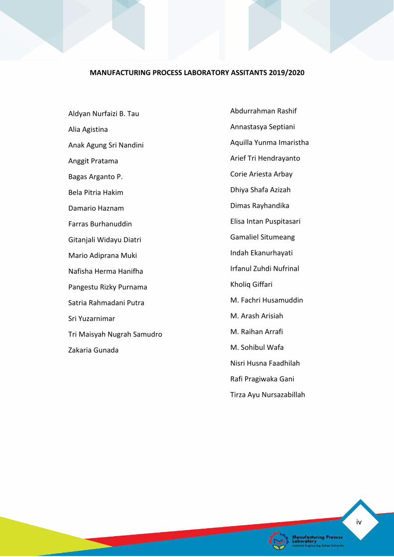
MANUFACTURING PROCESS LABORATORY ASSITANTS 2019/2020
Aldyan Nurfaizi B. Tau
Alia Agistina
Anak Agung Sri Nandini
Anggit Pratama
Bagas Arganto P.
Bela Pitria Hakim
Damario Haznam
Farras Burhanuddin
Gitanjali Widayu Diatri
Mario Adiprana Muki
Nafisha Herma Hanifha
Pangestu Rizky Purnama
Satria Rahmadani Putra
Sri Yuzarnimar
Tri Maisyah Nugrah Samudro
Zakaria Gunada
Abdurrahman Rashif
Annastasya Septiani
Aquilla Yunma Imaristha
Arief Tri Hendrayanto
Corie Ariesta Arbay
Dhiya Shafa Azizah
Dimas Rayhandika
Elisa Intan Puspitasari
Gamaliel Situmeang
Indah Ekanurhayati
Irfanul Zuhdi Nufrinal
Kholiq Giffari
M. Fachri Husamuddin
M. Arash Arisiah
M. Raihan Arrafi
M. Sohibul Wafa
Nisri Husna Faadhilah
Rafi Pragiwaka Gani
Tirza Ayu Nursazabillah

5
MANUFACTURING PROCESS
LABORATORY
Document
Number
MODULE 3.1 Form
Number
Valid 2019
Module Computer Aided Manufacturing
Labwork CAM Milling
Student Outcomes SO8. Excellent/ Very competent/ Competent in understanding the knowledge of communication techniques and the latest and most up-to-date technological developments
Learning Outcomes LO2. Following the development of technology related to industries such as advanced manufacturing technology, use of information technology to manage companies, green manufacturing, etc.

6
A. Tools and Requirements
Tools & Software Requirements
1. Personal Computer
2. Personal Gadget
3. Mastercam 2019
1. Labwork of Module 3.1
2. Personal gadget with internet connection
3. Stationary
B. References
Axsys, Inc. (2018). Retrieved from http://www.axsysinc.com/AxsysSoftwareSolutions.html
CNC Software, Inc. (2018). Retrieved from https://www.mastercam.com/en-
us/Solutions/Milling-Solutions/Multiaxis
CNC Software, Inc. (2018). 2D/3D Mill. Retrieved from Mastercam Web Site:
https://www.mastercam.com/en-us/Solutions/Milling-Solutions/2D-3D-Mill
CNC Software, Inc. (2019). Multiaxis. Retrieved from Mastercam Web Site:
https://www.mastercam.com/en-us/solutions/milling-solutions/multiaxis
CustomPartNet. (2007). Milling Process, Defect, Equipment. Retrieved from
COSTUMPART.NET: https://www.custompartnet.com/wu/milling
CustomPartNet. (n.d.). Milling Process, Defects, Equipment. Retrieved from
CustomPart.Net: https://www.custompartnet.com/wu/milling
In-House Solution, Inc. (2018). Retrieved from
https://www.inhousesolutions.com/mastercam-mill
Manufacturing Process Laboratory. (2018). Modul Praktikum Proses Manufaktur. Bandung:
Telkom University.
Markis, S., Mourszis, D., & Chryssolouris, G. (2012). Computer-Aided Manufactuing.
Mastercam. (n.d.). Retrieved from www.mastercam.com
Milling Process, Defects, Equipment. (n.d.). Retrieved from CustomPart.Net:
https://www.custompartnet.com/wu/milling
7
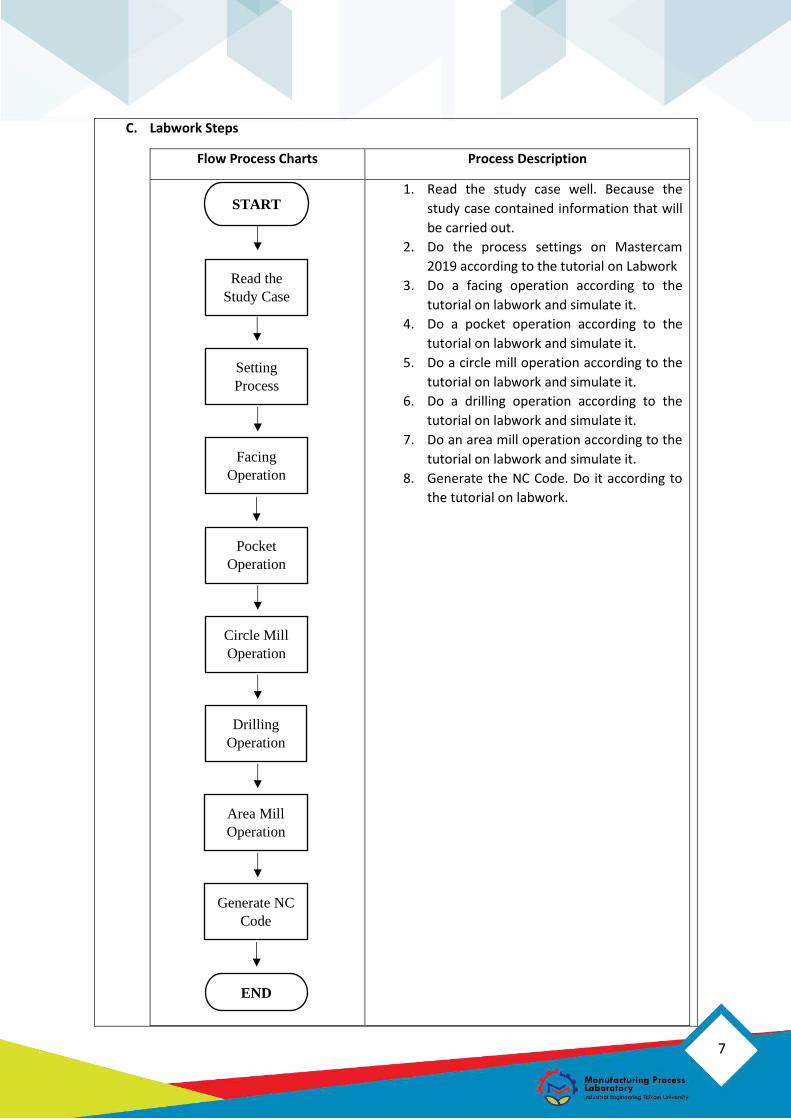
C. Labwork Steps
Flow Process Charts Process Description
1. Read the study case well. Because the
study case contained information that will
be carried out.
2. Do the process settings on Mastercam
2019 according to the tutorial on Labwork
3. Do a facing operation according to the
tutorial on labwork and simulate it.
4. Do a pocket operation according to the
tutorial on labwork and simulate it.
5. Do a circle mill operation according to the
tutorial on labwork and simulate it.
6. Do a drilling operation according to the
tutorial on labwork and simulate it.
7. Do an area mill operation according to the
tutorial on labwork and simulate it.
8. Generate the NC Code. Do it according to
the tutorial on labwork.
END
Generate NC
Code
Area Mill
Operation
Drilling
Operation
Circle Mill
Operation
Operation
Facing
Operation
Setting
Process
Read the
Study Case
START

8
MODULE 3.1
COMPUTER-AIDED MANUFACTURING (CAM: MILLING)
1.1 Student are able to understand the concept of Computer-aided Manufacturing.
1.2 Students are able to understand the concept of Milling Process.
1.3 Students are able to use Mastercam Milling.
2.1 Introduction Machining Process (Milling Process).
2.2 Computer-aided Manufacturing.
2.3 Mastercam.
2.4 Mastercam Milling Operations
1. OBJECTIVES
2. OUTLINES
9
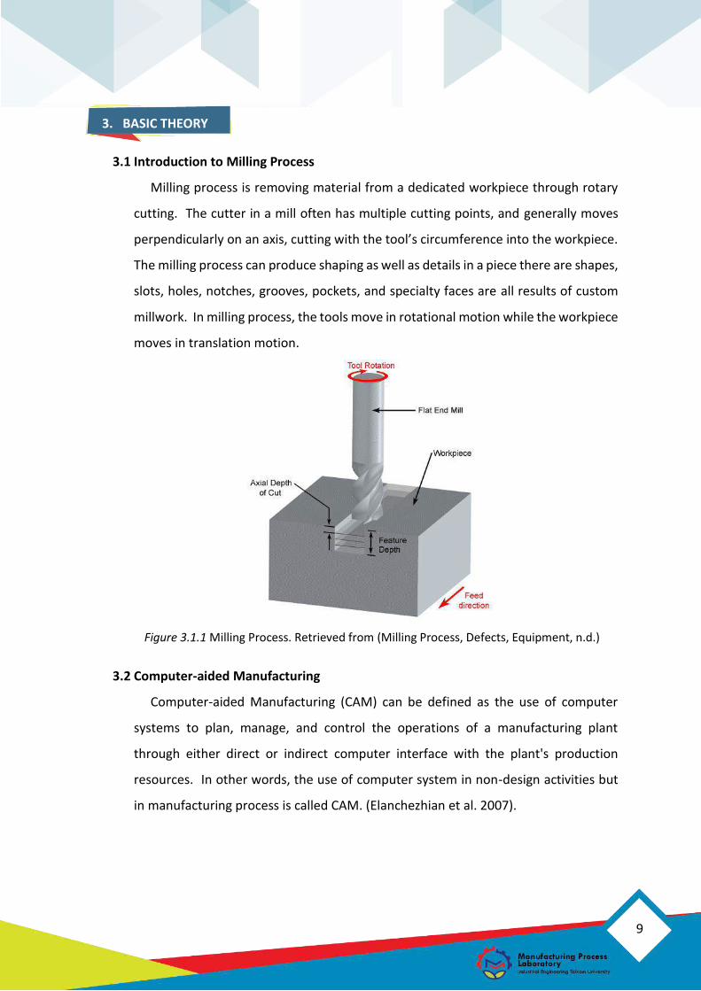
3.1 Introduction to Milling Process
Milling process is removing material from a dedicated workpiece through rotary
cutting. The cutter in a mill often has multiple cutting points, and generally moves
perpendicularly on an axis, cutting with the tool’s circumference into the workpiece.
The milling process can produce shaping as well as details in a piece there are shapes,
slots, holes, notches, grooves, pockets, and specialty faces are all results of custom
millwork. In milling process, the tools move in rotational motion while the workpiece
moves in translation motion.
Figure 3.1.1 Milling Process. Retrieved from (Milling Process, Defects, Equipment, n.d.)
3.2 Computer-aided Manufacturing
Computer-aided Manufacturing (CAM) can be defined as the use of computer
systems to plan, manage, and control the operations of a manufacturing plant
through either direct or indirect computer interface with the plant's production
resources. In other words, the use of computer system in non-design activities but
in manufacturing process is called CAM. (Elanchezhian et al. 2007).
3. BASIC THEORY
10
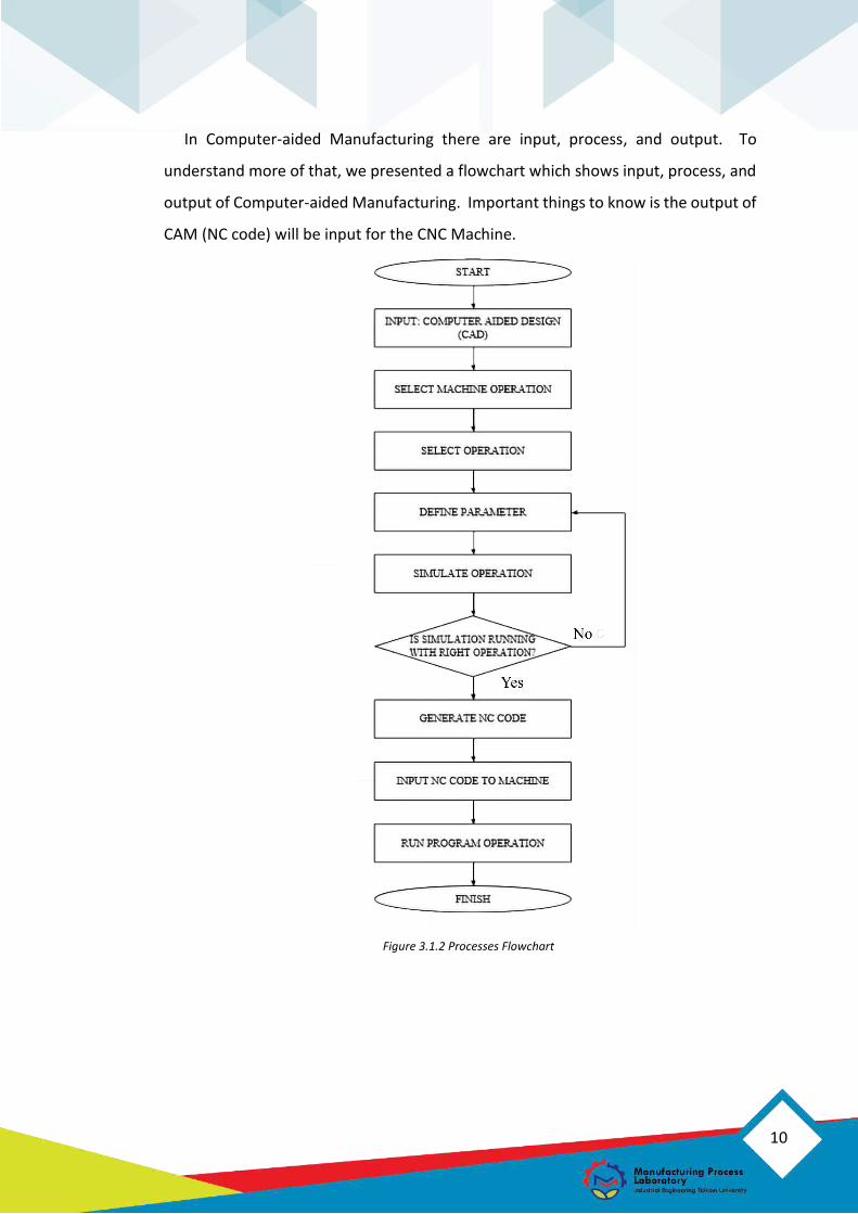
In Computer-aided Manufacturing there are input, process, and output. To
understand more of that, we presented a flowchart which shows input, process, and
output of Computer-aided Manufacturing. Important things to know is the output of
CAM (NC code) will be input for the CNC Machine.
Figure 3.1.2 Processes Flowchart
11
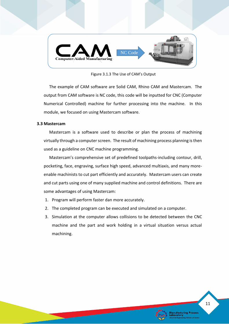
Figure 3.1.3 The Use of CAM’s Output
The example of CAM software are Solid CAM, Rhino CAM and Mastercam. The
output from CAM software is NC code, this code will be inputted for CNC (Computer
Numerical Controlled) machine for further processing into the machine. In this
module, we focused on using Mastercam software.
3.3 Mastercam
Mastercam is a software used to describe or plan the process of machining
virtually through a computer screen. The result of machining process planning is then
used as a guideline on CNC machine programming.
Mastercam’s comprehensive set of predefined toolpaths-including contour, drill,
pocketing, face, engraving, surface high speed, advanced multiaxis, and many more-
enable machinists to cut part efficiently and accurately. Mastercam users can create
and cut parts using one of many supplied machine and control definitions. There are
some advantages of using Mastercam:
1. Program will perform faster dan more accurately.
2. The completed program can be executed and simulated on a computer.
3. Simulation at the computer allows collisions to be detected between the CNC
machine and the part and work holding in a virtual situation versus actual
machining.
NC Code

12
3.4 Mastercam Milling Operations
The following types of operation process in Mastercam software are:
a. Mastercam 2D Milling Operation
Mastercam’s 2D toolpath deliver easy and optimized pocketing, contouring,
drilling, facing, and much more. 2D operation is used if the feeding area is clear
(view from top) and the surface of the feeding area is flat so that it can be feed
from above. Examples of products that use 2D Milling Operation is arm balancers.
Figure 3.1.4 Mastercam 2D Milling Operation
Table 3.1.1 Mastercam 2D Milling Operation
No. Operation Explanation Tools
1.
Dynamic Mill
Operation
Utilize the entire flute length of
the cutting tools to efficiently mill
pocket, open pocket, standing
cores or material left from
previous operation.
End Mill 3 Bull
2.
Swept 2D
Create a toolpath by sweeping
one boundary (the across
contour) along a second contour
(the along contour). End Mill 3 Bull
3.
Swept 3D
Create a toolpath by using a set-
boundaries, such as one across
boundary and one along
boundary, one across boundary
and two along boundaries, or two
across boundaries and one along
boundary.
End Mill 3 Bull

13
Table 3.1.2 Mastercam 2D Milling Operation (cont.)
No. Operation Explanation Tools
4.
Contour Operation
Contour toolpaths remove
material along a path defined by
chain of curves. Flat End Mill
5.
Dynamic Contour
Operation
Utilize the entire flute length of
the cutting tool to efficiently mill
material off walls supporting
closed or open chains. Flat End Mill

14
Table 3.1.1 Mastercam 2D Milling Operation (cont.)
No. Operation Explanation Tools
6.
Peel Mill Operation
Mill between two selected
contours or along a single
contour. Flat End Mill
7.
Area Mill Operation
Machine pockets, material that
other toolpaths leave behind, or
standing bosses and cores. Flat End Mill
8.
Blend Mill Operation
Morph smoothly between two
open chains. Create the toolpath
along or across the selected
chains.
Flat End Mill
9.
Slot Mill Operation
Efficiently machine around slots.
The slots must be closed and
include two parallel, straight
sides.
Flat End Mill
10.
Circle Mill
Mill circular pockets based in a
single point. Select either point
entities or center points of arcs. Flat End Mill
11.
Helix Bore
Machine a hole using helical
motion based on a single point.
Roughing passes are created as
cut down the hole.
Flat End Mill
12.
Pocket Operation
Clean out material from an
enclosed boundary in a finishing
or roughing operation. Flat End Mill
15
Table 3.1.1 Mastercam 2D Milling Operation (cont.)
No. Operation Explanation Tools
13.
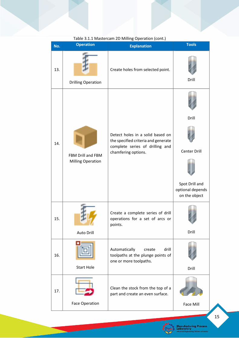
Drilling Operation
Create holes from selected point.
Drill
14.
FBM Drill and FBM
Milling Operation
Detect holes in a solid based on
the specified criteria and generate
complete series of drilling and
chamfering options.
Drill
Center Drill
Spot Drill and
optional depends
on the object
15.
Auto Drill
Create a complete series of drill
operations for a set of arcs or
points.
Drill
16.
Start Hole
Automatically create drill
toolpaths at the plunge points of
one or more toolpaths.
Drill
17.
Face Operation
Clean the stock from the top of a
part and create an even surface.
Face Mill
16
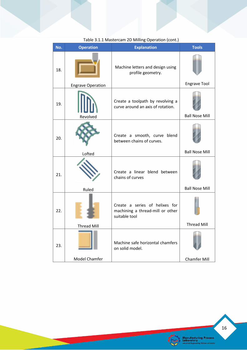
Table 3.1.1 Mastercam 2D Milling Operation (cont.)
No. Operation Explanation Tools
18.
Engrave Operation
Machine letters and design using profile geometry.
Engrave Tool
19.
Revolved
Create a toolpath by revolving a curve around an axis of rotation.
Ball Nose Mill
20.
Lofted
Create a smooth, curve blend between chains of curves.
Ball Nose Mill
21.
Ruled
Create a linear blend between chains of curves
Ball Nose Mill
22.
Thread Mill
Create a series of helixes for machining a thread-mill or other suitable tool
Thread Mill
23.
Model Chamfer
Machine safe horizontal chamfers on solid model.
Chamfer Mill
17
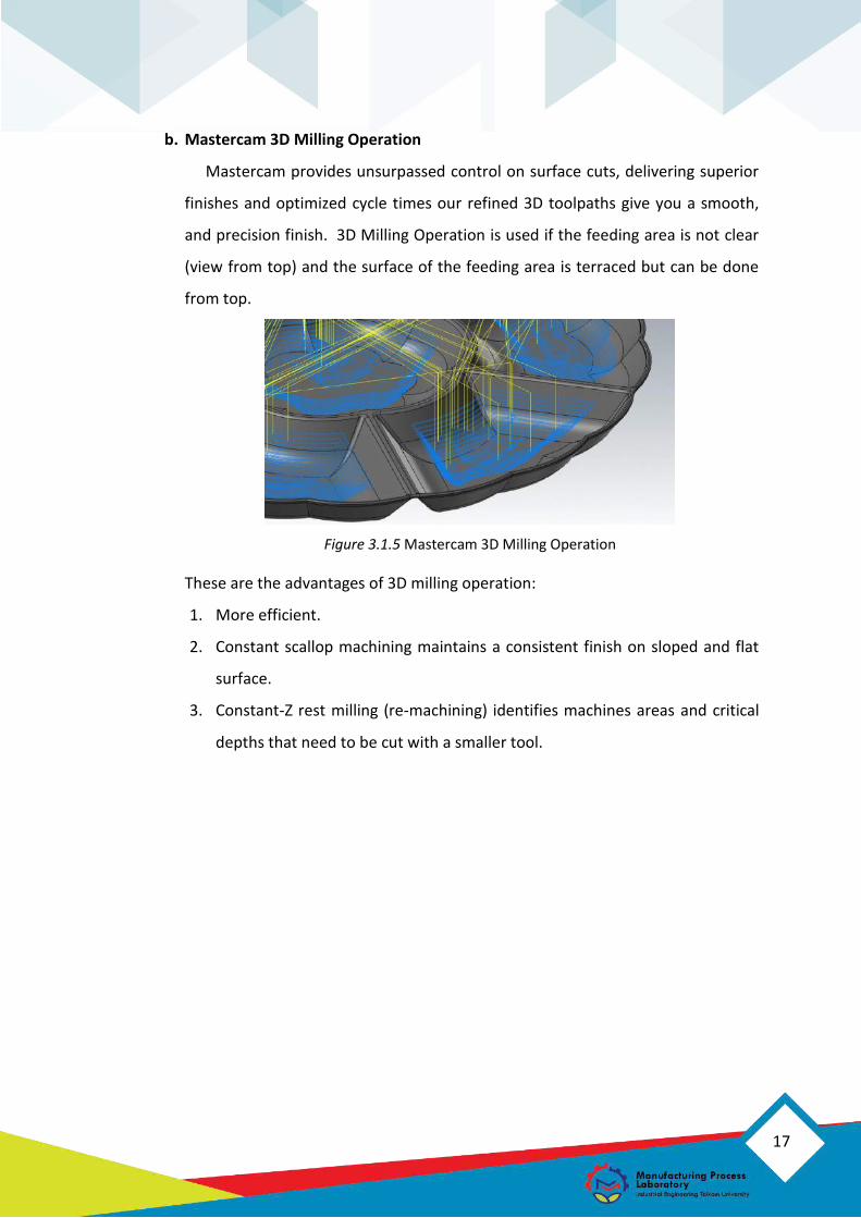
b. Mastercam 3D Milling Operation
Mastercam provides unsurpassed control on surface cuts, delivering superior
finishes and optimized cycle times our refined 3D toolpaths give you a smooth,
and precision finish. 3D Milling Operation is used if the feeding area is not clear
(view from top) and the surface of the feeding area is terraced but can be done
from top.
Figure 3.1.5 Mastercam 3D Milling Operation
These are the advantages of 3D milling operation:
1. More efficient.
2. Constant scallop machining maintains a consistent finish on sloped and flat
surface.
3. Constant-Z rest milling (re-machining) identifies machines areas and critical
depths that need to be cut with a smaller tool.
18
Table 3.1.3 Mastercam 3D Milling Operation
No. Operation Explanation Tools
1.
OptiRough
Operation
Remove the maximum amount of
material with the minimum number of
step downs.
End Mill 3 Bull
2.
Parallel
Operation
Remove stock quickly by using constant
Z depth cut at a specified angle in the
tool plane.
End Mill 3 Bull
3.
Area Roughing
Operation
Machine standing bosses and cores,
cavities and pockets, or material that
other toolpaths left behind.
End Mill 3 bull
4.
Radial
Create cutting passes that radiate
outwards from a central point.
End Mill 3 Bull

19
20
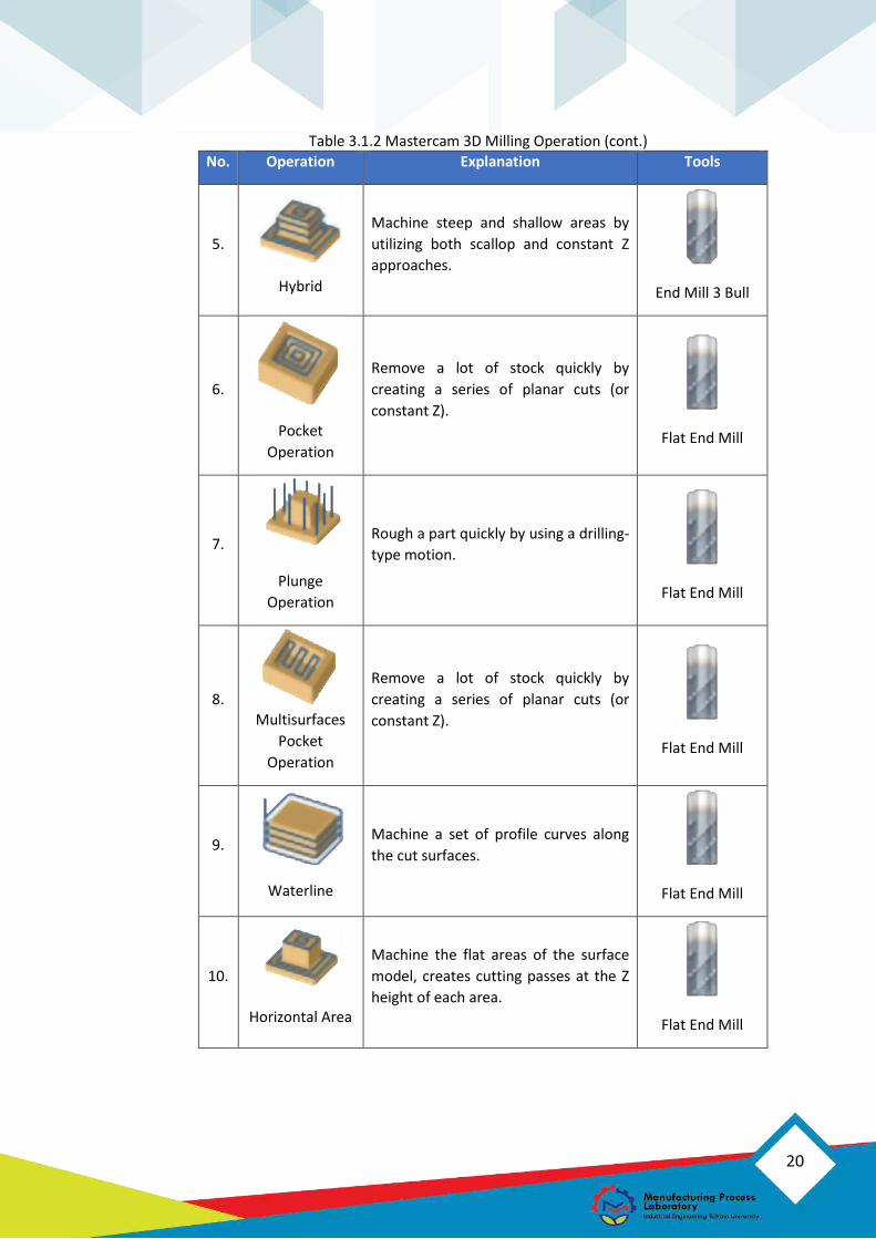
Table 3.1.2 Mastercam 3D Milling Operation (cont.)
No. Operation Explanation Tools
5.
Hybrid
Machine steep and shallow areas by
utilizing both scallop and constant Z
approaches.
End Mill 3 Bull
6.
Operation
Remove a lot of stock quickly by
creating a series of planar cuts (or
constant Z).
Flat End Mill
7.
Plunge
Operation
Rough a part quickly by using a drilling-
type motion.
Flat End Mill
8. Multisurfaces
Operation
Remove a lot of stock quickly by
creating a series of planar cuts (or
constant Z).
Flat End Mill
9.
Waterline
Machine a set of profile curves along
the cut surfaces.
Flat End Mill
10.
Horizontal Area
Machine the flat areas of the surface
model, creates cutting passes at the Z
height of each area.
Flat End Mill

21
Table 3.1.2 Mastercam 3D Milling Operation (cont.)
No. Operation Explanation Tools
11.
Equal Scallop
Create a toolpath with consistent
scallop motion relative to the stepover
distance.
Flat End Mill
12.
Project
Operation
Project geometry or toolpath from an
earlier operation onto surfaces.
Ball Nose Mill
13.
Raster
Suited for shallow surfaces or steeper
surfaces that are perpendicular to the
angle of the passes.
Ball Nose Mill
14.
Pencil
Clean out material by driving the cutter
tangent to two surfaces at a time.
Ball Nose Mill
15.
Blend
Create a toolpath along a surface
between selected chains.
Ball Nose Mill
16.
Scallop
Machine the surface model with a
constant stepover.
Ball Nose Mill
17.
Spiral
Create cutting passes where the tool
feeds into the part.
Ball Nose Mill

22
Table 3.1.2 Mastercam 3D Milling Process (cont.)
No. Operation Explanation Tools
18.
Contour
Create constant Z cuts around the
steep walls of the part.
Radius Mill
19.
Flowline
Follow the shape and direction of the
surfaces and creates a smooth and
flowing toolpath motion.
Lollipop Mill
c. Mastercam Multiaxis Operation
Multiaxis machining can intensely increase a company’s competitiveness.
Mastercam’s multiaxis interface is simple and intuitive to use. Mastercam has
complete control over the three crucial elements of multiaxis machining, which
are cut pattern, tool axis control, and collision avoidance. Multiaxis operation is
used when there are parts that can only be formed by side-feeding or cannot be
feed from top. An example of product that uses a multiaxis operation is a turbine.
Figure 3.1.6 Mastercam Multiaxis Milling Operation. Retrieved from
(CNC Software, Inc., 2019)
23
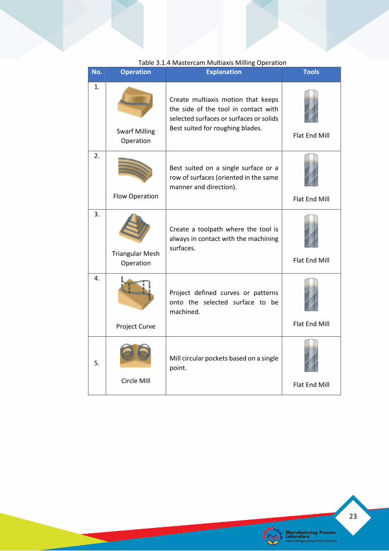
Table 3.1.4 Mastercam Multiaxis Milling Operation
No. Operation Explanation Tools
1.
Swarf Milling
Operation
Create multiaxis motion that keeps
the side of the tool in contact with
selected surfaces or surfaces or solids
Best suited for roughing blades.
Flat End Mill
2.
Flow Operation
Best suited on a single surface or a
row of surfaces (oriented in the same
manner and direction).
Flat End Mill
3.
Triangular Mesh
Operation
Create a toolpath where the tool is
always in contact with the machining
surfaces.
Flat End Mill
4.
Project Curve
Project defined curves or patterns
onto the selected surface to be
machined.
Flat End Mill
5.
Circle Mill
Mill circular pockets based on a single
point.
Flat End Mill
24
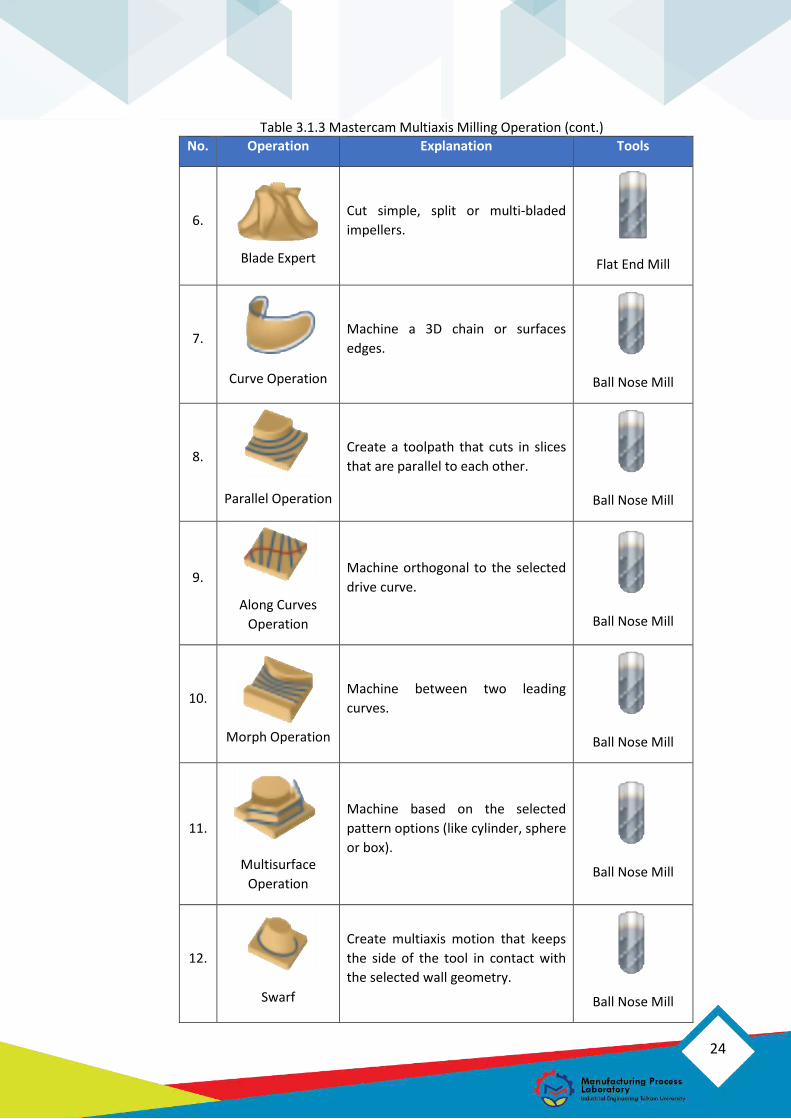
Table 3.1.3 Mastercam Multiaxis Milling Operation (cont.)
No. Operation Explanation Tools
6.
Blade Expert
Cut simple, split or multi-bladed
impellers.
Flat End Mill
7.
Curve Operation
Machine a 3D chain or surfaces
edges.
Ball Nose Mill
8.
Parallel Operation
Create a toolpath that cuts in slices
that are parallel to each other.
Ball Nose Mill
9.
Along Curves
Operation
Machine orthogonal to the selected
drive curve.
Ball Nose Mill
10.
Morph Operation
Machine between two leading
curves.
Ball Nose Mill
11.
Multisurface
Operation
Machine based on the selected
pattern options (like cylinder, sphere
or box).
Ball Nose Mill
12.
Swarf
Create multiaxis motion that keeps
the side of the tool in contact with
the selected wall geometry.
Ball Nose Mill
25
Table 3.1.3 Mastercam Multiaxis Milling Operation (cont.)
No. Operation Explanation Tools
13.
Rotary Advanced
Create a 4-axis rotary toolpath that
allows for more control over tool
motion.
Ball Nose Mill
14.
Deburr
Create a toolpath that break edges
and removal burrs.
Ball Nose Mill
15.
Port Operation
Create a roughing or finishing
toolpath for port geometry,
machining from top to bottom.
Lollipop Mill
16.
Port Expert
Cut a port or internal chamber of a
part.
Lollipop Mill
17.
Drill Operation
Drill holes by using the selected arcs.
Drill
18.
Rotary
Create a toolpath along or around
the selected rotary axis.
Drill
19.
Roughing
Rough out pocket geometry by
selecting the floor, wall or ceiling
surfaces to automatically generate a
toolpath.
End Mill 3 Bull
26
Axsys, Inc. (2018). Retrieved from
http://www.axsysinc.com/AxsysSoftwareSolutions.html
CNC Software, Inc. (2018). Retrieved from https://www.mastercam.com/en-
us/Solutions/Milling-Solutions/Multiaxis
CNC Software, Inc. (2018). Retrieved from www.mastercam.com:
https://www.mastercam.com/en-us/Solutions/Milling-Solutions/2D-3D-Mill
CustomPartNet. (2007). Milling Process, Defect, Equipment. Retrieved from
COSTUMPART.NET: https://www.custompartnet.com/wu/milling
In-House Solution, Inc. (2018). Retrieved from
https://www.inhousesolutions.com/mastercam-mill
Manufacturing Process Laboratory. (2018). Modul Praktikum Proses Manufaktur.
Bandung: Telkom University.
Markis, S., Mourszis, D., & Chryssolouris, G. (2012). Computer-Aided Manufactuing.
4. REFERENCES