manufacturing-technology-poovendan.pdf
DESCRIPTION
manufacturingTRANSCRIPT


THIS PAGE ISBLANK


Copyright © 2006 New Age International (P) Ltd., PublishersPublished by New Age International (P) Ltd., Publishers
All rights reserved.
No part of this ebook may be reproduced in any form, by photostat, microfilm,xerography, or any other means, or incorporated into any information retrievalsystem, electronic or mechanical, without the written permission of the publisher.All inquiries should be emailed to [email protected]
ISBN (10) : 81-224-2316-7
ISBN (13) : 978-81-224-2316-7
PUBLISHING FOR ONE WORLD
NEW AGE INTERNATIONAL (P) LIMITED, PUBLISHERS4835/24, Ansari Road, Daryaganj, New Delhi - 110002Visit us at www.newagepublishers.com

Dedicatedto
My Father Late Shri Sada Ram

THIS PAGE ISBLANK

PREFACE
Manufacturing and workshop practices have become important in the industrial envi-ronment to produce products for the service of mankind. The knowledge of manufacturingpractices is highly essential for all engineers and technocrats for familiarizing themselveswith modern concepts of manufacturing technologies. The basic need is to provide theoreti-cal and practical knowledge of manufacturing processes and workshop technology to all theengineering students. Therefore, an attempt has been made through this book to presentboth the theoretical and practical knowledge of these subjects. Considering the generalneeds of engineering students in the country and the fact that they hardly get any exposureto hand tools, equipments, machines and manufacturing setups, a basic course in manufac-turing science remains a core subject for all the branches of engineering. This book coversmost of the syllabus of manufacturing processes/technology, workshop technology and work-shop practices for engineering diploma and degree classes prescribed by different universi-ties and state technical boards. While preparing the manuscript of this book, the examina-tion requirements of the engineering students have also been kept in mind. The book iswritten in very simple language so that even an average student can easily grasp the subjectmatter. Some comparisons have been given in tabular form and the stress has been givenon figures for better understanding of tools, equipments, machines and manufacturing set-ups used in various manufacturing shops. The contents include exposure to bench work andfitting, smithy and forging, sheet metal work, wood and wood working, casting, welding andmachine shop practices. At the end of each chapter, a number of questions have beenprovided for testing the student’s understanding about the concept of the subject. The wholetext has been organized in twenty six chapters.
The first chapter presents the brief introduction of the subject with modern conceptsof manufacturing technology needed for the competitive industrial environment. Chapter 2provides the necessary details of plant and shop layouts. General industrial safety measuresto be followed in various manufacturing shops are described in detail in chapter 3.
Chapters 4–8 provide necessary details regarding fundamentals of ferrous materials,non-ferrous materials, melting furnaces, properties and testing of engineering materials andheat treatment of metals and alloys.
Chapters 9–13 describe various tools, equipments and processes used in various shopssuch as carpentry, pattern making, mold and core making, foundry shop. Special castingmethods and casting defects are also explained at length.
Chapters 14–16 provide basic knowledge of mechanical working of metals. Fundamentalconcepts related to forging work and other mechanical working processes (hot and coldworking) have been discussed at length with neat sketches.

Chapter 17 provides necessary details of various welding and allied joining processessuch as gas welding, arc welding, resistance welding, solid state welding, thermochemicalwelding, brazing and soldering.
Chapters 18–19 describe sheet metal and fitting work in detail. Various kinds of handtools and equipments used in sheet metal and fitting shops have been described using neatsketches.
Chapters 20–24 provide construction and operational details of various machine toolsnamely lathe, drilling machine, shaper, planer, slotter, and milling machine with the helpof neat diagrams.
Chapter 25 deals with technique of manufacturing of products with powder metallurgy.The last chapter of the book discusses the basic concepts of quality control and inspectiontechniques used in manufacturing industries.
The author strongly believes that the book would serve not only as a text book for thestudents of engineering curriculum but would also provide reference material to engineersworking in manufacturing industries.
Although every care has been taken to check misprints and mistakes, yet it is difficultto claim perfection. Any errors, omissions and suggestions for improvement of this volumewill be thankfully acknowledged and included in the next edition.
RAJENDER SINGH
(viii)

ACKNOWLEDGEMENT
On completion of the book ‘Introduction to Basic ManufacturingProcesses and Workshop Technology’, foremost I acknowledge the graceof God; and the blessing of my father late Sh. Sada Ram, my mother Smt.Sona Devi, my respected teacher Prof. G.S. Sekhon and my elders. I wish toacknowledge my sincere thanks to Sh. Shailendra Kumar, lecturer in HinduCollege of Engineering, Sonepat, Haryana for assisting me at various stagesduring preparation of the manuscript. I also acknowledge the students andcolleagues whose association has given me the experience of teaching thisand related subjects and hence the manuscript of this book could be possible.I am very happy to record my sense of gratitude to my wife Promilla, daugh-ter Swati and son Ravi Kant for their patience, understanding and moralsupport without which it would have not been possible for me to completethis book.
Finally, I am thankful to our publisher, New Age International (P) Ltd.Publishers for bringing out the book in a record time and such a nice format.
RAJENDER SINGH

THIS PAGE ISBLANK
CONTENTS
Preface (vii)
Acknowledgements (ix)
1. Introduction 1
2. Plant and Shop Layout 17
3. Industrial Safety 26
4. Ferrous Materials 51
5. Non-Ferrous Materials 76
6. Melting Furnaces 102
7. Porperties and Testing of Metals 116
8. Heat Treatment 130
9. Carpentry 152
10. Pattern and Core Making 179
11. Foundry Tools and Equipments 197
12. Mold and Core Making 208
13. Casting 241
14. Forging 260
15. Hot Working of Metals 282
16. Cold Working 293
17. Welding 306
18. Sheet Metal Work 348
19. Fitting 364
20. Metal Cutting 397
21. Lathe Machine 406
22. Drilling Machine 422
23. Shaper, Planer and Slotter 434
24. Milling 447
25. Powder Metallurgy 458
26. Inspection and Quality Control 466
Index 475

THIS PAGE ISBLANK

1
INTRODUCTION
1.1 INTRODUCTION
Manufacturing is the backbone of any industrialized nation. Manufacturing and technical staffin industry must know the various manufacturing processes, materials being processed, toolsand equipments for manufacturing different components or products with optimal processplan using proper precautions and specified safety rules to avoid accidents. Beside above, allkinds of the future engineers must know the basic requirements of workshop activities interm of man, machine, material, methods, money and other infrastructure facilities neededto be positioned properly for optimal shop layouts or plant layout and other support serviceseffectively adjusted or located in the industry or plant within a well planned manufacturingorganization.
The complete understanding of basic manufacturing processes and workshop technologyis highly difficult for any one to claim expertise over it. The study deals with several aspectsof workshops practices also for imparting the basic working knowledge of the differentengineering materials, tools, equipments, manufacturing processes, basic concepts of electro-mechanical controls of machine tools, production criteria’s, characteristics and uses of varioustesting instruments and measuring or inspecting devices for checking components or productsmanufactured in various manufacturing shops in an industrial environment. It also describesand demonstrates the use of different hand tools (measuring, marking, holding and supportingtools, cutting etc.), equipments, machinery and various methods of manufacturing that facilitateshaping or forming the different existing raw materials into suitable usable forms. It dealswith the study of industrial environment which involves the practical knowledge in the areaof ferrous and non ferrous materials, their properties and uses. It should provide the knowledgeof basic workshop processes namely bench work and fitting, sheet metal, carpentry, patternmaking, mould making, foundry, smithy, forging, metal working and heat treatment, welding,fastening, machine shop, surface finishing and coatings, assembling inspection and qualitycontrol. It emphasizes on basic knowledge regarding composition, properties and uses ofdifferent raw materials, various production processes, replacement of or improvement overa large number of old processes, new and compact designs, better accuracy in dimensions,quicker methods of production, better surface finishes, more alternatives to the existingmaterials and tooling systems, automatic and numerical control systems, higher mechanizationand greater output.
1CHAPTER
2 Introduction to Basic Manufacturing Processes and Workshop Technology
1.2 SCOPE OF STUDY
Today’s competitive manufacturing era of high industrial development and research, is beingcalled the age of mechanization, automation and computer integrated manufacturing. Due tonew researches in the manufacturing field, the advancement has come to this extent thatevery different aspect of this technology has become a full-fledged fundamental and advancedstudy in itself. This has led to introduction of optimized design and manufacturing of newproducts. New developments in manufacturing areas are deciding to transfer more skill to themachines for considerably reduction of manual labor. The scope of the subject of workshoptechnology and manufacturing practices is a extremely wide as it specifies the need of greatercare for man, machine, material and other equipments involving higher initial investment byusing proper safety rule and precautions. The through and deep knowledge in the course ofstudy of this important subject is therefore becoming essential for all kinds of engineers tohave sound foundation in their profession. Therefore the course of study of this subjectprovides a good theoretical background and a sound practical knowledge to the engineeringstudents and workshop staff. One should also be aware of the following terms for betterunderstanding of the scope of the study
1.3 MANUFACTURING ENGINEERING Manufacturing is derived from the Latin word manufactus, means made by hand. In moderncontext it involves making products from raw material by using various processes, by makinguse of hand tools, machinery or even computers. It is therefore a study of the processesrequired to make parts and to assemble them in machines. Process Engineering, in itsapplication to engineering industries, shows how the different problems related to developmentof various machines may be solved by a study of physical, chemical and other laws governingthe manufacturing process. The study of manufacturing reveals those parameters which canbe most efficiently being influenced to increase production and raise its accuracy. Advancemanufacturing engineering involves the following concepts—
1. Process planning.2. Process sheets.3. Route sheets.4. Tooling.5. Cutting tools, machine tools (traditional, numerical control (NC), and computerized
numerical control (CNC).6. Jigs and Fixtures.7. Dies and Moulds.8. Manufacturing Information Generation.9. CNC part programs.
10. Robot programmers.11. Flexible Manufacturing Systems (FMS), Group Technology (GT) and Computer
integrated manufacturing (CIM).
1.4 PRODUCTION PROCESS
It is the process followed in a plant for converting semi- finished products or raw materialsinto finished products or raw materials into finished products. The art of converting raw

Introduction 3
material into finished goods with application of different types of tools, equipments, machinetools, manufacturing set ups and manufacturing processes, is known as production. Generallythere are three basic types of production system that are given as under.
1. Job production
2. Batch production
3. Mass production
Job production comprises of an operator or group of operators to work upon a single joband complete it before proceeding to the next similar or different job. The productionrequirement in the job production system is extremely low. It requires fixed type of layoutfor developing same products.
Manufacturing of products (less in number say 200 to 800) with variety of similar partswith very little variation in size and shape is called batch production. Whenever the productionof batch is over, the same manufacturing facility is used for production of other batch productor items. The batch may be for once or of periodical type or of repeated kinds after someirregular interval. Such manufacturing concepts are leading to GT and FMS technology.Manufacturing of products in this case requires process or functional layout.
Where as mass production involves production of large number of identical products (saymore than 50000) that needs line layout type of plant layout which is highly rigid type andinvolves automation and huge amount of investment in special purpose machines to increasethe production.
1.5 PROCESS PLANNING
Process planning consists of selection of means of production (machine-tools, cutting tools,presses, jigs, fixtures, measuring tools etc.), establishing the efficient sequence of operation,determination of changes in form, dimension or finish of the machine tools in addition to thespecification of the actions of the operator. It includes the calculation of the machining time,as well as the required skill of the operator. It also establishes an efficient sequence ofmanufacturing steps for minimizing material handling which ensures that the work will bedone at the minimum cost and at maximum productivity. The basic concepts of processplanning are generally concerned with the machining only. Although these concepts may alsobe extended to other processes such as casting, forging, sheet metal forming, assembling andheat treatment as well.
1.6 MANUFACTURING PROCESS
Manufacturing process is that part of the production process which is directly concernedwith the change of form or dimensions of the part being produced. It does not include thetransportation, handling or storage of parts, as they are not directly concerned with thechanges into the form or dimensions of the part produced.
1.7 CLASSIFICATION OF MANUFACTURING PROCESSES
For producing of products materials are needed. It is therefore important to know thecharacteristics of the available engineering materials. Raw materials used manufacturing ofproducts, tools, machines and equipments in factories or industries are extracted from ores.The ores are suitably converted the metal into a molten form by reducing or refining processes

4 Introduction to Basic Manufacturing Processes and Workshop Technology
in foundries. This molten metal is poured into moulds for providing commercial castings,called ingots. Such ingots are then processed in rolling mills to obtain market form ofmaterial supply in form of bloom, billets, slabs and rods. These forms of material supply arefurther subjected to various manufacturing processes for getting usable metal products ofdifferent shapes and sizes in various manufacturing shops. All these processes used inmanufacturing concern for changing the ingots into usable products may be classified into sixmajor groups as primary shaping processes, secondary machining processes, metal formingprocesses, joining processes, surface finishing processes and processes effecting change inproperties. These are discussed as under.
1.7.1 Primary Shaping ProcessesPrimary shaping processes are manufacturing of a product from an amorphous material.Some processes produces finish products or articles into its usual form whereas others do not,and require further working to finish component to the desired shape and size. Castings needre-melting of scrap and defective ingots in cupola or in some other melting furnace and thenpouring of the molten metal into sand or metallic moulds to obtain the castings. Thus theintricate shapes can be manufactured. Typical examples of the products that are produced bycasting process are machine beds, automobile engines, carburetors, flywheels etc. The partsproduced through these processes may or may not require to under go further operations.Some of the important primary shaping processes is:
(1) Casting, (2) Powder metallurgy, (3) Plastic technology, (4) Gas cutting, (5) Bending and(6) Forging.
1.7.2. Secondary or Machining ProcessesAs large number of components require further processing after the primary processes. Thesecomponents are subjected to one or more number of machining operations in machine shops,to obtain the desired shape and dimensional accuracy on flat and cylindrical jobs. Thus, thejobs undergoing these operations are the roughly finished products received through primaryshaping processes. The process of removing the undesired or unwanted material from theworkpiece or job or component to produce a required shape using a cutting tool is known asmachining. This can be done by a manual process or by using a machine called machine tool(traditional machines namely lathe, milling machine, drilling, shaper, planner, slotter). Inmany cases these operations are performed on rods, bars and flat surfaces in machine shops.These secondary processes are mainly required for achieving dimensional accuracy and a veryhigh degree of surface finish. The secondary processes require the use of one or moremachine tools, various single or multi-point cutting tools (cutters), job holding devices, markingand measuring instruments, testing devices and gauges etc. for getting desired dimensionalcontrol and required degree of surface finish on the workpieces. The example of parts producedby machining processes includes hand tools machine tools instruments, automobile parts,nuts, bolts and gears etc. Lot of material is wasted as scrap in the secondary or machiningprocess. Some of the common secondary or machining processes are—
(1) Turning, (2) Threading, (3) Knurling, (4) Milling, (5) Drilling, (6) Boring, (7) Planning,(8) Shaping, (9) Slotting, (10) Sawing, (11) Broaching, (12) Hobbing, (13) Grinding, (14) Gearcutting, (15) Thread cutting and (16) Unconventional machining processes namely machiningwith Numerical Control (NC) machines tools or Computer Numerical Control (CNC) machinestools using ECM, LBM, AJM, USM setups etc.

Introduction 5
1.7.3 Metal Forming ProcessesForming processes encompasses a wide variety of techniques, which make use of suitableforce, pressure or stresses, like compression, tension and shear or their combination to causea permanent deformation of the raw material to impart required shape. These processes arealso known as mechanical working processes and are mainly classified into two major categoriesi.e., hot working processes and cold working processes. In these processes, no material isremoved; however it is deformed and displaced using suitable stresses like compression,tension, and shear or combined stresses to cause plastic deformation of the materials toproduce required shapes. Such processes lead to production of directly usable articles whichinclude kitchen utensils, rods, wires, rails, cold drink bottle caps, collapsible tubes etc. Someof the important metal forming processes are:
Hot working Processes(1) Forging, (2) Rolling, (3) Hot spinning, (4) Extrusion, (5) Hot drawing and (6) Hot spinning.
Cold working processes(1) Cold forging, (2) Cold rolling, (3) Cold heading, (4) Cold drawing, (5) Wire drawing,
(6) Stretch forming, (7) Sheet metal working processes such as piercing, punching, lancing,notching, coining, squeezing, deep drawing, bending etc.
1.7.4 Joining ProcessesMany products observed in day-to-day life, are commonly made by putting many parts togethermay be in subassembly. For example, the ball pen consists of a body, refill, barrel, cap, andrefill operating mechanism. All these parts are put together to form the product as a pen.More than 800 parts are put together to make various subassemblies and final assembly ofcar or aero-plane. A complete machine tool may also require to assemble more than 100 partsin various sub assemble or final assembly. The process of putting the parts together to formthe product, which performs the desired function, is called assembly. An assemblage of partsmay require some parts to be joined together using various joining processes. But assemblyshould not be confused with the joining process. Most of the products cannot be manufacturedas single unit they are manufactured as different components using one or more of the abovemanufacturing processes, and these components are assembled to get the desired product.Joining processes are widely used in fabrication and assembly work. In these process two ormore pieces of metal parts are joined together to produce desired shape and size of theproduct. The joining processes are carried out by fusing, pressing, rubbing, riveting, screwingor any other means of assembling. These processes are used for assembling metal parts andin general fabrication work. Such requirements usually occur when several pieces are to bejoined together to fabricate a desired structure of products. These processes are used developingsteam or water-tight joints. Temporary, semi-permanent or permanent type of fastening tomake a good joint is generally created by these processes. Temporary joining of componentscan be achieved by use of nuts, screws and bolts. Adhesives are also used to make temporaryjoints. Some of the important and common joining processes are:
(1) Welding (plastic or fusion), (2) Brazing, (3) Soldering, (4) Riveting, (5) Screwing,(6) Press fitting, (7) Sintering, (8) Adhesive bonding, (9) Shrink fitting, (10) Explosive welding,(11) Diffusion welding, (12) Keys and cotters joints, (13) Coupling and (14) Nut and bolt joints.
1.7.5 Surface Finishing ProcessesSurface finishing processes are utilized for imparting intended surface finish on the surfaceof a job. By imparting a surface finishing process, dimension of part is not changed functionally;
6 Introduction to Basic Manufacturing Processes and Workshop Technology
either a very negligible amount of material is removed from the certain material is added tothe surface of the job. These processes should not be misunderstood as metal removingprocesses in any case as they are primarily intended to provide a good surface finish or adecorative or protective coating on to the metal surface. Surface cleaning process also calledas a surface finishing process. Some of the commonly used surface finishing processes are:
(1) Honing, (2) Lapping, (3) Super finishing, (4) Belt grinding, (5) Polishing, (6) Tumbling,(7) Organic finishes, (8) Sanding, (9) deburring, (10) Electroplating, (11) Buffing, (12) Metalspraying, (13) Painting, (14) Inorganic coating, (15) Anodizing, (16) Sheradising, (17) Parkerizing,(18) Galvanizing, (19) Plastic coating, (20) Metallic coating, (21) Anodizing and (22) Sand blasting.
1.7.6 Processes Effecting Change in PropertiesProcesses effecting change in properties are generally employed to provide certain specificproperties to the metal work pieces for making them suitable for particular operations or use.Some important material properties like hardening, softening and grain refinement are neededto jobs and hence are imparted by heat treatment. Heat treatments affect the physicalproperties and also make a marked change in the internal structure of the metal. Similarlythe metal forming processes effect on the physical properties of work pieces Similarly shotpeening process, imparts fatigue resistance to work pieces. A few such commonly used processesare given as under:
(1) Annealing, (2) Normalising, (3) Hardening, (4) Case hardening, (5) Flame hardening,(6) Tempering, (7) Shot peeing, (8) Grain refining and (9) Age hardening.
In addition, some allied manufacturing activities are also required to produce the finishedproduct such as measurement and assembly.
1.8. PRODUCT SIMPLIFICATION AND STANDARDISATION
The technique of simplification and standardization of product is closely inter-related thatleads to higher efficiency in production, better quality and reduced production cost. Simplificationis a process of determining limited number of grades, types and sizes of a components orproducts or parts in order to achieve better quality control, minimize waste, simplify productionand, thus, reduce cost of production. By eliminating unnecessary varieties, sizes and designs,simplification leads to manufacture identical components or products for interchangeabilityand maintenance purposes of assembly of parts. Standardization is the important step towardsinterchangeable manufacture, increased output and higher economy. The technique ofstandardization comprises of determining optimal manufacturing processes, identifying thebest possible engineering material, and allied techniques for the manufacture of a product andadhering to them very strictly so long as the better standards for all these are not identified.Thus definite standards are set up for a specified product with respect to its quality, requiredequipment, machinery, labor, material, process of manufacture and the cost of production.The identified standard with time for a specified product should never be taken as final forever because improvement is always possible. It must accommodate the outcome of all thenew researches in the manufacturing areas in order to keep pace with increasing globalcompetition. Improvements over the existing standards in all respects should always bewelcomed. The different standards prevailing in different industries may be of the types ofmanagerial, design, manufacturing and technical needs. Managerial standards are applicableto administrative functions within industry. These include the company policy, accountingprocedures, personnel policies, performance evaluation, control of expenditures, safety aspects,
Introduction 7
security procedures and regulations, etc. where as design, manufacturing and technical standardsare needed for manufacturing concepts of the industry. These include design and manufacturingtechniques, practices, materials and parts, supplies, methods of testing, drafting method,abbreviations and symbols, specifications and nomenclature, etc.
1.9 INSPECTION AND QUALITY CONTROL
A product is manufactured to perform desired functions. It must have a specified dimensionsuch as length, width, height, diameter and surface smoothness to perform or accomplish itsintended function. It means that each product requires a defined size, shape and othercharacteristics as per the design specifications. For manufacturing the product to the specifiedsize, the dimensions should be measured and checked during and after the manufacturingprocess. It involves measuring the size, smoothness and other features, in addition to theirchecking. These activities are called measurement and inspection respectively.
In the era of globalization, every industry must pay sufficient attention towards maintainingquality because it is another important requirement or function of a production unit. If amanufacturing concern wants to survive for longer time and to maintain its reputation amongthe users, it should under all condition apply enough efforts not only to keep up the standardof quality of its products once established but to improve upon the same from time to time.For this, every manufacturing concern must maintain a full-fledged inspection and qualitycontrol department which inspects the product at different stages of its production. Vigilantinspection of raw materials and products depends upon the entire process of standardization.The production unit of manufacturing concern must produce identical products. However aminor variation may be allowed to a predetermined amount in their finished dimensions ofthe products. The two extremities of dimensions of the product are called limits. All the partsof which the finished dimensions lie within these limits are acceptable parts. This facilitateseasy and quicker production, easy inspection, requires less skill on the part of worker andaccommodates a slight inaccuracy in the machine as well, resulting in an over all reductionin the production cost of the part.
1.10 MECHANIZATION AND AUTOMATION
Mechanization means something is done or operated by machinery and not by hand.Mechanization of the manufacturing means is milestone oriented trend towards minimizingthe human efforts to the extent of its possibility, by adopting mechanical and electrical meansor methods for automating the different manufacturing processes. Such a trend may be in thearea of automating and mechanizing the processes of material handling, loading and unloadingof components, actual operations performed on the job or transportation, etc. But, no feedbackis provided by the process, operation or machinery. Extension of mechanization of the productionprocess is termed as automation and it is controlled by a closed loop system in which feedbackis provided by the sensors. It controls the operations of different machines automatically. Theautomatic control may be applied for some operations or for all the operations of a machineor group of machines. Accordingly the machine will be known as semi-automatic or fullyautomatic. The term was identified shortly after the World War II at the Ford Motor Companyto describe the automatic handling of materials and parts between the process operations.The word ‘automation’ is derived from the Greek word automatos meaning self-acting.Automation can also be defined as the process of following a predetermined sequence ofoperations with little or no human intervention, using specialized equipment and devices that

8 Introduction to Basic Manufacturing Processes and Workshop Technology
perform and control the manufacturing process. Automation is a word that has many meaningsin the industry today. Automatic machines of all kinds existed long before the term automationwas conceived. But, it should be noted that all automatic machines do not come under thecategory of automation. Automation is a technology concerned with the application mechanical,electronic, and computer based systems to operate and control production.
Every machine should involve some automation, may be to a lesser degree or to a higherextent to which is mainly governed by economic considerations. Automation means a systemin which many or all of the processes in the production, movement, and inspection of partsand material are performed under control by the self-operating devices called controllers. Thisimplies that the essential elements of automation comprise of mechanization, sensing, feedback,and control devices. The reasons why one should go for automation are:
1. Increased productivity
2. Reduced cost of labor and dependence on labor shortages
3. Improved quality
4. Reduced in-process inventory
5. Reduced manufacturing time
6. Reduced dependence on operator skills
7. Increased safety or reduced risk of humans.
Automation can be classified into three categories, viz.
1. Fixed automation
2. Programmable automation
3. Flexible automation.
1.10.1 Fixed AutomationIt is also known as hard automation which is utilized to produce a standardized product suchas gears, nuts and bolts, etc. Even though the operating conditions can be changed, fixedautomation is used for very large quantity production of one or few marginally differentcomponents. Highly specialized tools, devices, equipment, special purpose machine tools, areutilized to produce a product or a component of a product very efficiently and at high productionrates with as low unit costs as possible relative to other alternative methods of manufacturing.
1.10.2 Programmable AutomationIn programmable automation, one can change the design of the product or even change theproduct by changing the program. Such technique is highly useful for the low quantityproduction of large number of different components. The equipments used for the manufacturingare designed to be flexible or programmable. The production normally carried out in batches.
1.10.3 Flexible AutomationThere is a third category possible between fixed automation and programmable automationthat is called flexible automation using Computer Aided Design (CAD) and Computer AidedManufacturing (CAD/CAM) activities. This is also called as flexible manufacturing system(FMS). It allows producing different products on the same equipment in any order or mix. Oneimportant example of programmable automation, in discrete manufacturing, is numericalcontrol. Robot is another example of programmable automation. Robot being integral part of

Introduction 9
FMS and Computer Integrated Manufacturing (CIM) system can do a large number ofmanufacturing tasks for replacing the human labor.
In the present globalized manufacturing scenario, the advancements of hardware andsoftware concepts using the mechatronics for fast mechanization and automation ofmanufacturing processes have become essential to be incorporated in the manufacturingareas.
1.11 COMPUTER AIDED MANUFACTURING (CAM)
The computer aided manufacturing implies manufacturing itself, aided or controlled bycomputers. In a wider sense, it denotes all the activities in the manufacturing environmentlike use of computers in inventory control, project management, material requirement planning,data acquisition, testing and quality control. Improved reliability in view of the bettermanufacturing methods and controls at the manufacturing stage, the products thusmanufactured as well as of the manufacturing system would be highly reliable. Since mostof the components of a CAM system would include integrated diagnostics and monitoringfacilities, they would require less maintenance compared to the conventional manufacturingmethods. Because of the Computer Numerical Control (CNC) machines used in productionand the part programs being made by the stored geometry from the design stage, the scraplevel would be reduced to the minimum possible and almost no rework would be necessary.Since all the information and controlling functions are attempted with the help of the computer,a better management control on the manufacturing activity is possible. All the above advantageswhen properly translated, would mean a lower total cost and consequently, higher finalearnings. Therefore any manufacturing activity in a production unit (job shop production ormass scale manufacture) can get the benefits of Computer Aided Manufacturing. However,better results can be obtained when the design and manufacturing activities are properlyintegrated. Also, when there is a large variety of products or minor changes required in theexisting production programme, CAM can easily manage the necessary changes or alterations.Following are the main advantages of using CAM.
1. Greater design freedomAny changes that are required in design can be incorporated at any design stage without
worrying about any delays, since there would hardly be any in an integrated CAM environment.
2. Increased productivityIn view of the fact that the total manufacturing activity is completely organized through
the computer, it would be possible to increase the productivity of the plant.
3. Greater operating flexibilityCAM enhances the flexibility in manufacturing methods and changing of product lines.
4. Shorter lead timeLead times in manufacturing would be greatly reduced.
The integration of CAD and CAM systems is called Computer Integrated Manufacturing(CIM) system. The role of computer in manufacturing may be in two major groups namelycomputer monitoring and control of the manufacturing process and manufacturing supportapplications, which deal essentially with the preparations for act of manufacturing and postmanufacture operations. Computers are used in controlling machine tools and other materialhandling equipments.
10 Introduction to Basic Manufacturing Processes and Workshop Technology
1.12 KINDS OF PRODUCTION SYSTEMS
The choice of production type dictates the machine requirements, organizational system toa large extent, layout planning and inventory subsystems. Three main types of production arejob, batch and flow or process production. The simplest way is to classify based on productionand processes by lot size, namely single unit production, small lot production, moderate lotproduction, large lot production, and continuous production. The second classification comprisesthree categories, namely small size production of a large variety of products, medium-scaleproduction of a limited range of products, and a large-scale production of a small variety ofproducts. Obviously, this method is related to the number of product types and production lotsizes, and is an effective means of analyzing modern production management. The thirdclassification is related to the size of the production system expressed through the numberof employees or the amount of fixed assets involved, namely small production unit employingless than 30 employees, medium-small having 30 to 300 employees, medium with 301 to 2,000employees and large with 2001 to 15,000 employees, and a giant corporation employing morethan 15,000 employees
Job shop production deals the manufacture of very small lots, often of single jobs. Thismay be required in special situations for the purpose of proving a design, making prototypes,in tool making or for special purpose applications. In view of the very small lot, no specialpurpose machines or tooling can be economically justified. Hence, the manufacturing has tobe carried on with the general purpose machines and tooling, which is a very lengthy andoften an error prone process.
1.13 MANUFACTURING SYSTEM
Manufacturing basically implies making of goods or articles and providing services to meetthe needs of mankind. It creates value by useful application of physical and mental-labor inthe process. It is a chain of interrelated activities of production process and other supportservices activities of an manufacturing environment such as order processing, product design,design and manufacturing of tools, die, mould, jigs, fixtures and gauges, selection of material,planning, managing and maintaining control of the processes, production, and reliable qualityof processed product in a systematic and sequential manner with proper coordination,cooperation and integration of the whole manufacturing system that will lead to economicalproduction and effective marketing of proposed product in the minimum possible time. It is,therefore, evident that manufacturing today is not a one man activity as it was in the initialstages, wherein all the physical and mental inputs were applied by a single craftsman. Thesedays it has become totally a team work which consists of several components interactingtogether in a dynamic manner. This entire domain of manufacturing is known as ManufacturingSystem, which takes the required inputs and delivers the products for the customer. It is,therefore, evident that manufacturing today is not a one man activity as it was in thepreliminary stages, wherein all the physical and mental inputs were provided by a singleworkman. Today it is a team work which consists of several components interacting togetherin a dynamic manner to provide the required physical and mental inputs at appropriate stagesto impart desired results. This entire domain of manufacturing is known as ManufacturingSystem, which takes the required inputs and delivers the products for the customer.
Manufacturing system requires a large number of activities, few independent and restsmostly interrelated. The manufacturing activities in a manufacturing system jointly contribute
Introduction 11
towards economic and qualitatively acceptable production of desired articles in minimumpossible time. As per the need of the customer, the products are identified and their demandsare determined roughly for market forecast by considering present and future competition.Products that may render the desired service over its expected life satisfactorily as perrequirement of customers are identified in terms of their demand, conceived and developedfor securing orders by the sales department. Once the product design activity is over and thedesign finalized from all angles, functional, aesthetic, material selection, safety, economy, etc.,it is followed by preparation of production drawings of the product assembly and its componentsincluding a bill of materials. This is the stage where a make or buy decision has to be takenin order to decide as to which components are to be bought from outside and which are tobe manufactured within the concern. It is followed by process planning i.e. selection of thebest process and an its parameters, design of jigs, fixtures and dies, selection of tooling,programming of tool path as per need, for the components to be produced in-house. Animportant activity in process planning within the organization is also to involve latest researchand development findings, through which the old processes are improved and new one’s aredeveloped in order to ensure better quality and economic production. The interaction ofdifferent manufacturing activities in a manufacturing system can also be further enhanced bythe use of computer and hence leading CIM. The real manufacturing or production activityis carried out on the shop. The layout of the shop floor has a significant influence on the toolsrequired to be coordinated in order to an economical and high quality production of variouscomponents. It should be such that it ensures timely movement of raw materials, diesmoulds, jigs and fixtures and finished components, adequate safety to men, material andmachinery, enables timely inspection and quality control and minimizes handling time formaterial and parts, etc. During actual manufacturing a lot of different activities are calledmanagement function. Various engineers play an important role in the organizational functionof a manufacturing concern. They are required to ensure proper movement of the material,tools and parts as per their specialized jobs in industry.
1.14 PRODUCT DEVELOPMENT
A product development has to go through the following concepts of product engineering whichare given as under.
Product functions1. Product specifications2. Conceptual design3. Ergonomics and aesthetics4. Standards5. Detailed design6. Prototype development7. Testing8. Simulation9. Design for manufacture
10. Design for assembly11. Drafting.
Now let us consider the manufacturing environment of a given product. How does theproduct idea originate. Market forces determine the need for a product. Expertise on the part
12 Introduction to Basic Manufacturing Processes and Workshop Technology
of the company estimates the likely demand and probable profitability and decides on the bestmode of designing and manufacturing the desired product.
Traditionally, after the design of the product, the part prints are released for production.The production engineering section first considers the feasibility of production of the product.Having ascertained its feasibility, process planning is done so that the product can bemanufactured at the lowest possible cost. Any redesign that is needed for improving theproducibility of the product without compromising on its functionality would have to be doneat this stage. Having decided on the process plan for manufacture, the necessary actions areundertaken for its implementation. These are making of the tooling required, acquiring ofnew equipment or tools, procurement of the raw materials, releasing of the detailed operationalinstructions to the shop floor, etc. The conventional methods of manufacturing are generallyinefficient and dependent on operator skills. These methods consume more time, have highcosts, and give poor accuracy.
Product design is an activity which needs to be well organized and take into account allinfluences that are likely to be responsible for the success of the product under development.A product here means a single component which is functional in itself like a wrench or anassembly of a large number of components all of which will contribute to the functioning ofthe part such as an automobile engine. The complexity of the design process certainly increaseswith the number and diversity of components present in the final part. Since there are sucha large number of influencing factors, it is impossible to specify a design procedure for eachcomponent. Here we are interested in developing some common guidelines and steps that areneeded to proceed for a successful product design and manufacture.
From the above discussion it can inferred that products can be manufactured by morethan one processes. Therefore several alternatives for manufacturing products are available.The selection of a suitable process is depended upon the factors including volume of production,properties of the components, technical viability of process, economy involved and desiredquality. Based upon the volume of product the manufacturing activity can be identified interms of job shop production, batch production and mass production
1.15 COMPUTERS IN MANUFACTURING INDUSTRIES
Factors governing increased productivity, more accuracy, greater flexibility of shapes, andreduced manufacturing costs are forcing the manufacturing concerns to use computers indesign, manufacturing and other allied functions of industrial activities. With an increase inthe need for quality manufacturing along with the factors such as short lead time and shortproduct lives and increasing consumer awareness as regards the quality of the product, it isbecoming increasingly important for the manufacturers to initiate steps to achieve all these.The developments in microelectronics in the recent past have made higher computationalability available at a low cost. Therefore, it becomes imperative that manufacturing takesadvantage of the availability of low cost and also using yet more powerful computers. Computershave been in use in manufacturing industries since 1960. Initially they were in use only insupportive functions such as inventory control purchase accounting, etc. In to day’s time,computer applications have progressed considerably in all areas of design and manufacturinginvolving CAD and CAM. This however needs to be emphasized that all the benefits of CADand CAM can be achieved only if these two important functions are effectively interfaced. Thisinterfacing is known as CAD/CAM. It involves the flow of information in both the directions.With the result the parts and assemblies are designed keeping in view the limitations and
Introduction 13
capabilities of the processes and materials. Consequently, newer and superior products can beproduced more quickly and at lower costs.
Today, computers are not only used in manufacturing but they play also an importantrole in all manufacturing related activities such as business or financial management, factorylevel production management, CIM technologies, CAD, feature and solid modelling, andCAM, manufacturing information, manufacturing system. The important sub-activities ofindustrial environment have been identified to support with the use of computer in themanufacturing industries. These are given as under:
1. Business or Financial Management1. Costing
2. Sales and Marketing
3. Purchase Order Control
4. Vendors
5. Subcontracting
6. Personnel.
2. Factory Level Production management1. Planning
2. Production Management
3. Manufacturing production scheduling (MPS)
4. Material requirement planning (MRP)
5. Just in time (JIT)
6. Bill of Materials
7. Capacity Planning
8. Inventory Control.
3. CIM Technologies1. Computer Networks
2. System Design and Analysis
3. Distributed Processing
4. Database Management Manufacturing
5. Modelling and Simulation
6. Expert Systems
7. Quality Engineering.
4. Computer Aided Design (CAD)This area is also known Feature and Solid Modelling
1. Variational and Parametric
2. Modelling
3. Computer Graphics
4. Graphic Standards

14 Introduction to Basic Manufacturing Processes and Workshop Technology
5. Inter-graphics exchange specification (IGES)
6. Data exchange file (DXF)
7. Manufacturing Robot Programming
8. Design Analyses Tools
9. Programming
10. Finite element modelling (FEM)
11. Finite element analysis (FEA)
12. Simulation
13. Mechanisms
14. Test and Analysis
15. Design Tools Mechanical
16. Hydraulic, Electronics, etc.
5. Computer Aided Manufacturing (CAM)This involves activities related to manufacturing information and manufacturing system
which are given as under—
Manufacturing Information1. Generation
2. Process Planning
3. Production Planning
4. Computer numerical control (CNC) part Programming
5. Robot Programming
6. Coordinate measuring machine (CMM) Programming.
Manufacturing System1. Production Activity
2. Machining
3. Assembly
4. Material Handling
5. Storage
6. Production Control
7. Loading
8. Scheduling
9. Balancing
10. Capacity Planning
11. Quality Control.
One of the most important components for getting various benefits associated withcomputer applications in manufacturing is the common databases associated with all aspectsof manufacturing. In fact, all the modules in the CAM would actually be sharing the databasecreated in any module. Any module would be able to modify the data as required for that

Introduction 15
particular application. This approach reduces the work involved in maintaining the productdatabase and at the same time includes the latest modifications for any aspect related tomanufacturing. In contrast to the common database approach, it is possible that sometimesindividual modules in the production aspects may be taken from different vendors. In thiscase care need to be taken that information is properly transmitted between the modules andthe data updating in all the modules takes place properly and at the right time. Some of abovementioned manufacturing activities are controlled by computers. These activities are commonlyidentified using the following terms.
1. Computer Aided Design (CAD)
2. Computer Aided Engineering (CAE)
3. Computer Aided Design And Drafting (CADD)
4. Computer Aided Process Planning (CAPP)
5. Computer Aided Tool Design (CATD)
6. Computer Aided Manufacturing (CAM)
7. Computer Aided Numerical Control (NC) Part Programming
8. Computer Aided Scheduling
9. Computer Aided Material Requirement Planning, etc.
10. Flexible Manufacturing System (FMS)
11. Group Technology (GT)
12. Computer aided Testing (CAT).
1.16 QUESTIONS1. How do you classify the manufacturing processes?
2. Distinguish between ‘primary’ and ‘secondary’ processes?
3. Discuss primary shaping processes. Give also a brief account of the primary shaping processes.
4. Explain the secondary or machining processes. Give also a brief account of these processes.
5. Describe and name the types of joining processes, surface finishing operations and theprocesses employed for changing the properties of manufactured components.
6. Write a short note on assembly process.
7. Write short notes on:
(a) Simplification, (b) Standardization, (c) Inspection and quality control, (d) Interchangeability,(e) Mechanization, (f) Automation, (g) Mechatronics.
8. What do you understand from the terms Manufacturing, Process plan, Maintenance?
9. Explain the term ‘Manufacturing System’. What all it encompasses and how an integratedapproach is made for making an economical and competitive product? Describe how the useof computers helps in increasing manufacturing efficiency.
10. Explain the terms CAD, CAM, NC, CAD/CAM, MRP, FMS and CIM?
11. Write a short note on Group Technology?
12. Explain the influence exerted by the computers on the manufacturing scene?
13. Briefly explain the conventional process of the product cycle in the conventional manufacturingenvironment.

16 Introduction to Basic Manufacturing Processes and Workshop Technology
14. What are the functions that get benefited by the use of computers in design and manufacturingfunctions?
15. Briefly explain the various automation aspects used in manufacturing activities.
16. Write down the advantages which can be gained by the adoption of CAD?
17. Describe the advantages which can be gained by the adoption of CAM?
18. Write down the advantages which can be gained by the adoption of FMS?
19. Write down the advantages which can be gained by the adoption of manufacturing productionscheduling (MPS)?
20. Write down the advantages which can be gained by the adoption of Material RequirementPlanning (MRP)?
21. Explain the main advantages which can be gained by the adoption of CIM?

17
PLANT AND SHOP LAYOUT
2.1 INTRODUCTION
In a manufacturing organization, a job to be manufactured spends most of the time in movingand waiting. For reduction of this moving and waiting time of jobs/parts, it is necessary tohave proper layout and proper scheduling procedure. Plant layout specifies the position of theoverall arrangement of the various facilities such as equipments, material, manpower, materialshandling, service facilities, and passage required to facilitate efficient operation of production systemof the plant within the area of the site selected previously. Shop layout in manufacturing plantalso forms an integral part of factory planning or plant layout. Plant layout begins with thedesign the position of the factory building and goes up to the location and movement of a worktable of the machine. All the manufacturing facilities such as equipments, raw materials,machinery, tools, fixtures, workers, etc. are given a proper place in each shop of themanufacturing plant. Plant layout of an industrial organization plays an important role inscientific management and is defined as :
“Plant layout is such a systematic and efficient functional arrangement ofvarious departments, machines, tools, equipment and other supports services of anindustrial organization that will facilitate the smooth processing of the proposedor undertaken product in the most effective, most efficient and most economicalmanner in the minimum possible time”
Plant layout of an industrial organization comprises of all the aspects connected with theindustrial enterprise, viz., grounds, buildings, machinery, equipment, departments, methodsof manufacturing, factory services, material handling, flow of production, working conditions,hygiene, labor and shipment of goods, etc. It does not necessarily mean planning a newenterprise only. However, it also involves minor improvements, here and there, in the existinglayout, expansion of the exiting plant, re-layout of the existing plant and layout of a newproposed plant. In a best possible plant layout, material handling and transportation is minimizedand efficiently controlled. Bottlenecks and points of congestions are eliminated so that theraw material and semi-finished goods move fast from one work station to another. Workstations are designed suitably to facilitate the smooth processing of the proposed or undertakenproduct in the most effective, most efficient and most economical manner in the minimumpossible time. Optimal spaces are allocated to production centers and service centers. Theprimary goal of plant layout is to maximize profits by setting up the best possible arrangementsof all plant facilities to the maximum advantage of reducing the cost of production of theproposed product.
2CHAPTER

18 Introduction to Basic Manufacturing Processes and Workshop Technology
2.2. OBJECTIVES OF GOOD PLANT LAYOUT
Good plant layout comprises of best possible arrangement of the buildings, men, machine andmaterials for processing a under taken product. The main objectives of a good plant layoutinvolves minimum material movement, smooth flow of the product in the plant, full utilizationof the space of the plant, provide adequate safety and satisfaction to the plant workers, evolvesufficient flexibility in the arrangement of the above factors so as to suit the minor futurechanges, if any and facilitates an effective supervision. It helps to integrate all the abovefactors in such a way that the best compromise and coordination among them is achieved.The movements of workers and manufacturing staffs within the plant are minimized. Waitingtime of the semi-finished and finished products should be reduced to the minimum. Workingconditions as far as possible should be safer and better for the satisfaction of the workers.There should be an increased flexibility for changes in product design and for future expansion.There should be full utilization of whole space of the shop and plant layout. The workmethods and reduced production cycle times should be improved and the plant maintenancemust be simpler. There should be increased productivity and better product quality withreduced capital cost. A good layout facilitates materials to move through the plant at thedesired speed with the minimum possible cost.
2.3. IMPORTANT FACTORS FOR INSTALLATION OF A PLANT
The important factors while planning for installation of plant include availability of space,power, water, raw material, good climatic conditions, good means of communication, ancillaries,low local taxes and similar other economic considerations, marketing facilities for the plannedproduct, space for process disposal and skilled and unskilled labor locally. One has to keep inmind the possibilities of utilization and sale of the process wastes and by-products of theplanned industry. Decision of manufacturing new product, financial and other aids, facilitiesfor expansion presence of related industries, local by laws and securities, hospitality are alsoimportant factors which one must keep in mind for location of an enterprise. After finalizingthe size and location of the plant, the next step is to design the inner layout of the plant toplan out the sequence of different shops and their locations accordingly to specifications ofmaterial and product, manufacturing processes, type of production, material handling facilities,system and facilities for storing, inter-dependability of one shop over the other, links amongvarious shops, service facilities and lighting and ventilation. Next, the internal arrangementof the above mentioned infracturctral facilities of different shops are identified. Thisidentification is termed as shop layout. The main factors namely size and type of equipment,number of machines to be installed, floor area required for working on each machine, powerrequirements for the machines, requirements of factory services, sequence of operations tobe followed, visibility to all the machines for proper supervision and control, type of driveused, safe working conditions, provision of stores within the shop, i.e. for tools, instruments,finished parts and consumable materials, etc. affects the layout of the plant. A good plantlayout should meet the following basic requirement:
1. Integration of manufacturing centre facilities in terms of man, machine and material.
2. Movements of production personnel and material handling should be minimized.
3. Smooth and continuous flow of production or manufacturing work with least possiblebottlenecks and congestion points.
4. Floor space utilization should be optimum as for as possible.
Plant and Shop Layout 19
5. Working place should be free from pollution and safe working conditions shouldprevail in each shop of the plant.
6. The handling of raw material, semi finished and finished product should be shouldbe tackled optimally and effectively
7. Plant layout and shop layouts must be flexible to facilitate changes in productionrequirements
8. There should be better working environment in term of proper light, ventilationand other amenities such as drinking water and toilets for welfare for themanufacturing personnel
2.4. MERITS OF A GOOD PLANT LAYOUT
The main advantages of a good plant layout involve effectively and economical utilizationof entire floor space of the plant, increased rate of production, reduced men and machinehours per unit of production, reduced material handling, minimal production delays, effectiveutilization of men, machinery, material and other factory support services, reduced overallproduction time, elimination of large amount of paper work, significant reduction in theindirect expenses, considerable reduction in inventory work for material, promote effectivesupervision, facilitate easy flow of men, tools and material, promote flexibility in arrangementto suit the future changes, promotes better planning and effective control, facilitates betterand easier maintenance of plant and machinery, provides safer and healthier working conditionsthereby improving the morale of the workmen, provides the material as well as psychologicalsatisfaction to the workers and enhance overall efficiency of the plant. The major merits ofa good plant layout are given as under:
1. Reduced men and machine hours per unit of production,
2. Effectively and economical utilization of entire floor space of the plant,
3. Work flow is smooth and continuous
4. Work in process inventory is less
5. Production control is better
6. Manufacturing time is less
7. Relatively less floor area is required
8. Material handling is less.
2.5. TYPES OF LAYOUTS
The fulfilling the objectives of a good layout as per yearly product requirement and producttypes, the layouts are classified into four major categories namely fixed or position layout,line or product layout, process or functional layout and combination or group layout. Eachkind of layouts is explained with respective merit, demerits and application as under.
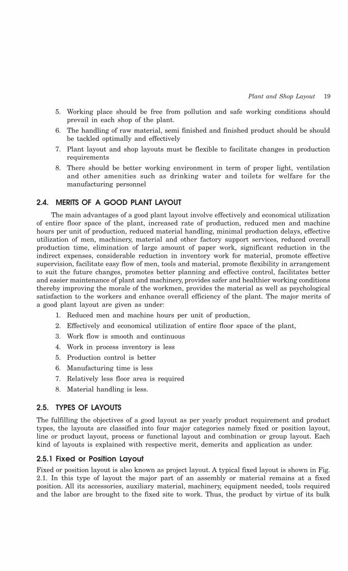
2.5.1 Fixed or Position LayoutFixed or position layout is also known as project layout. A typical fixed layout is shown in Fig.2.1. In this type of layout the major part of an assembly or material remains at a fixedposition. All its accessories, auxiliary material, machinery, equipment needed, tools requiredand the labor are brought to the fixed site to work. Thus, the product by virtue of its bulk
20 Introduction to Basic Manufacturing Processes and Workshop Technology
or weight remains at one location. Therefore the location of the major assembly, semiassembly component and material is not disturbed till the product is ready for dispatch. Thislayout is suitable when one or a few pieces of an item are to be manufactured and materialforming or treating operation requires only tools or simple machines. This layout is highlypreferable when the cost of moving the major piece of material is high and the responsibilityof product quality by one skilled workman or group of skilled workers is expected. This typeof layout is mainly adopted for extremely large items manufactured in very small quantitysuch as ships, aero planes, boilers, reactors etc. It main merit of this layout is the minimummovement of men, material, and tooling during manufacturing process. This layout is highflexible as the type of product and the related processes can be easily changed without anychange in the layout. The merit and demerit of this type of layout is given as under.
M en
Too ls
Components
W orkp laceFinishedproductto Store
Fig. 2.1 Typical project layout
MeritsIts main merits are—
1. Layout is highly flexible for varieties of products having intermittent demand as thetype of product and the related processes can be easily altered without any changein the layout.
2. There is a minimum movement of men, material, and tooling during manufacturingprocess.
3. The material is drastically reduced.
4. Highly skilled operators are required to complete the work at one point andresponsibility for quality is fixed on one person or the assembly crew.
5. Every personnel of manufacturing team is responsible for quality work formanufacturing the product.
DemeritsThe major demerits of this layout are
1. The cost of equipment handling is very high.
2. Labors and equipments are difficult to utilize fully.
3. It is limited to large items only.
ApplicationsThis type of layout is mostly adopted for extremely large items manufactured in very
small quantity such as ships, aero planes, aircraft, locomotive, ship assembly shops, shipyards,boilers, reactors etc.
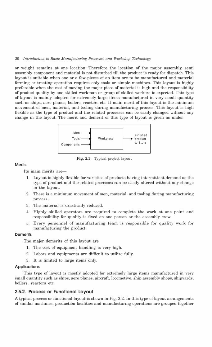
2.5.2. Process or Functional LayoutA typical process or functional layout is shown in Fig. 2.2. In this type of layout arrangementsof similar machines, production facilities and manufacturing operations are grouped together

Plant and Shop Layout 21
according to their functions. Machine tools of one kind are positioned together so that all thesimilar operations are performed always at the same place e.g. all the lathes may be groupedtogether for all kinds of turning and threading operations, all drilling machines in one areafor carrying out drilling work, all tapping machines in one area for carrying out tapping work,all milling machines in one area for carrying out milling work all buffing and polishingmachines at one place for carrying out surface finishing work, and so on. This type of layoutis normally preferred for the industries involved in job order type of production andmanufacturing and/or maintenance activities of non- repetitive type. This layout needs not tohave to be changed every time of the product or component changes. Also the breakdown ofany machine does not affect the production. This type of layout is highly suitable for batchproduction.
Shap ing M illing Drilling
S
S
S
S
S
S
S
S
M M
M
M
A
A
M
M
A
A
Assem bly
G rind ing
Rece iv ing andshipp ing sto re
D D
D
G
G G
G G
D
G
Fig. 2.2 Typical functional layout
MeritsThe major merits of this layout are :
1. There exists a wide flexibility regarding allotment of work to equipment and workers.
2. There is a better utilization of the available equipment.
3. Comparatively less numbers of machines are needed in this layout and hence thusreducing capital investment.
4. There is an improved product quality, because the supervisors and workers attendto one type of machines and operations.
5. Varieties of jobs coming as different job orders thus make the work more interestingfor the workers.
6. Workers in one section are not affected by the nature of the operations carried outin another section. For example, a lathe operator is not affected by the rays of thewelding as the two sections are quite separate.
22 Introduction to Basic Manufacturing Processes and Workshop Technology
DemeritsThe major demerits of this layout are :
1. This layout requires more space in comparison to line or product layout for thesame amount of production.
2. Production control becomes relatively difficult in this layout.
3. Raw material has to travel more which increases material handling and the associatedcosts.
4. This layout requires more efficient co-ordination and inspections.
5. Increased material handling cost due to more movement of process raw material tovarious paths
6. More material in process remains in queue for further operations.
7. Requires large in-process inventory.
8. Completion of same product takes more time.
Application1. This layout is used for batch or moderate production.
2. It specify path for group technology.
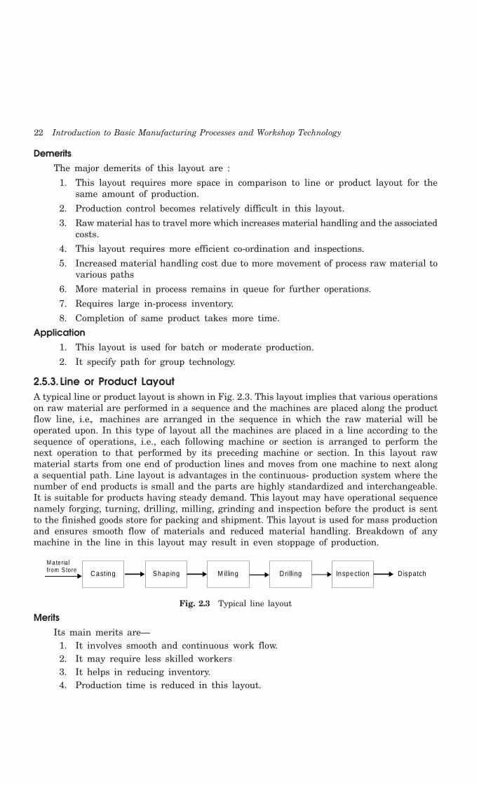
2.5.3. Line or Product LayoutA typical line or product layout is shown in Fig. 2.3. This layout implies that various operationson raw material are performed in a sequence and the machines are placed along the productflow line, i.e., machines are arranged in the sequence in which the raw material will beoperated upon. In this type of layout all the machines are placed in a line according to thesequence of operations, i.e., each following machine or section is arranged to perform thenext operation to that performed by its preceding machine or section. In this layout rawmaterial starts from one end of production lines and moves from one machine to next alonga sequential path. Line layout is advantages in the continuous- production system where thenumber of end products is small and the parts are highly standardized and interchangeable.It is suitable for products having steady demand. This layout may have operational sequencenamely forging, turning, drilling, milling, grinding and inspection before the product is sentto the finished goods store for packing and shipment. This layout is used for mass productionand ensures smooth flow of materials and reduced material handling. Breakdown of anymachine in the line in this layout may result in even stoppage of production.
Casting
M a teria lfrom S tore Shap ing M illing Drilling Inspection D ispatch
Fig. 2.3 Typical line layout
MeritsIts main merits are—
1. It involves smooth and continuous work flow.2. It may require less skilled workers3. It helps in reducing inventory.4. Production time is reduced in this layout.

Plant and Shop Layout 23
5. Better coordination, simple production planning and control are achieved in thislayout.
6. For the same amount of production, less space requirements for this layout.
7. Overall processing time of product is very less.
8. This layout involves automatic material handling, lesser material movements andhence leads to minimum possible cost of manufacturing.
DemeritsThe major demerits of this layout as compared with process layout are—
1. It is very difficult to increase production beyond the capacities of the productionlines.
2. When single inspector has to look after many machines, inspection becomes difficult
3. This layout is very less flexible for product change.
4. The rate or pace rate of working depends upon the output rate of the slowestmachine and hence leading to excessive idle time for other machines if the productionline is not adequately balanced.
5. Machines being put up along the line, more machines of each type have to beinstalled for keeping a few as stand by, because if on machine in the line fails, itmay lead to shut down of the complete production line. That is why the line orproduct layout involves heavy capital investments.
ApplicationsIt is used in assembly work.
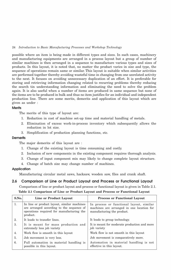
2.5.4.Combination LayoutFig. 2.4 shows a typical combination type of layout for manufacturing different sizes of crankshafts. It is also known as group layout. A combination of process and product layoutscombines the advantages of both types of layouts. Most of the manufacturing sections arearranged in process layout with manufacturing lines occurring here and there scatteredwherever the conditions permit. These days, the most of manufacturing industries haveadopted this kind of layout. In this type of layout, a set of machinery or equipment is groupedtogether in a section, and so on, so that each set or group of machines or equipment is usedto perform similar operation s to produce a family of components. A combination layout is
Raw
Mat
eria
l
Pro
cess
Lay
out
Fin
ishe
d P
rodu
cts
L ine Layout
3
3
3
3
4
4
5
5
2
2
3
3
1
1
1
1
Fig. 2.4 Typical combination layout
24 Introduction to Basic Manufacturing Processes and Workshop Technology
possible where an item is being made in different types and sizes. In such cases, machineryand manufacturing equipments are arranged in a process layout but a group of number ofsimilar machines is then arranged in a sequence to manufacture various types and sizes ofproducts. In this layout, it is noted that, no matter the product varies in size and type, thesequence of operations remain same or similar. This layout is suitable when similar activitiesare performed together thereby avoiding wasteful time in changing from one unrelated activityto the next. It focuses on avoiding unnecessary duplication of an effort. It is preferable forstoring and retrieving information changing related to recurring problems thereby reducingthe search tin understanding information and eliminating the need to solve the problemagain. It is also useful when a number of items are produced in same sequence but none ofthe items are to be produced in bulk and thus no item justifies for an individual and independentproduction line. There are some merits, demerits and application of this layout which aregiven as under :
MeritsThe merits of this type of layout are:
1. Reduction in cost of machine set-up time and material handling of metals.
2. Elimination of excess work-in-process inventory which subsequently allows thereduction in lot size.
3. Simplification of production planning functions, etc.
DemeritsThe major demerits of this layout are :
1. Change of the existing layout is time consuming and costly.
2. Inclusion of new components in the existing component requires thorough analysis.
3. Change of input component mix may likely to change complete layout structure.
4. Change of batch size may change number of machines.
ApplicationManufacturing circular metal saws, hacksaw, wooden saw, files and crank shaft.
2.6 Comparison of Line or Product Layout and Process or Functional LayoutComparison of line or product layout and process or functional layout is given in Table 2.1.Table 2.1 Comparison of Line or Product Layout and Process or Functional Layout
S.No. Line or Product Layout Process or Functional Layout
1. In line or product layout, similar machinesare arranged according to the sequence ofoperations required for manufacturing theproduct.
2. It leads to transfer lines.
3. It is meant for mass production andextremely less job variety
4. Work flow is smooth in this layout
5. Job movement is very less.
6. Full automation in material handling ispossible in this layout.
In process or functional layout, similarmachines are arranged in one location formanufacturing the product.
It leads to group technology.
It is meant for moderate production and morejob variety
Work flow is not smooth in this layout
Job movement is comparatively more.
Automation in material handling is noteffective in this layout.

Plant and Shop Layout 25
7. Machine utilization is poor in this layout.
8. Capital investment required is more in thislayout.
9. Inventory requirement is less.
10. Breakdown of one machine affects greatly inthis layout.
11. Production planning and control is easy.
12. Quality of product is not so good.
13. Work flexibility is very less in this layout
14. Space required for same amount ofproduction is less.
15. Time taken in completion of product is less.
16. Less skilled workers are requiredcomparatively.
17. Monotony in working is more because jobsare repetitive in nature in this layout.
18. It is used in mass production or assemblywork.
2.7 QUESTIONS1. What do you understand by the term plant layout?
2. Name and explain different factors responsible for selection of the site for installation of anew plant layout.
3. What are the major objectives of plant layout?
4. What are the common advantages of a good plant layout?
5. Explain the various kinds of plant layout and the situations in which each type is used.
6. Compare process layout and product layout.
7. List out the equipments required for a sheet metal shop, carpentry shop, foundry shop,smithy and forging shop. Draw also the layouts of the above shops.
8. Prepare a layout for fitting shop and machine shop.
Machinery utilization is better in this layout.
Capital investment required is comparativelyless in this layout.
Inventory requirement is comparativelymore.
Breakdown of one machine does not affect somuch in this layout.
Production planning and control iscomparatively difficult.
Quality of product quality is better
Work flexibility is more in this layout
Space required for same amount of productionis comparatively more.
Time taken in completion of product is more.
More skilled workers are required.
Monotony in working is less because jobs arenon-repetitive in this layout.
It is used in job order production ormaintenance work of non-repetitive type.

Industrial Safety 27
by safety measures. Every industrial personnel are required to contribute the efforts towardssafety. For ensuring industrial safety, the first factory act in India was passed by the GovernorGeneral of India on 23rd Sept., 1948. It was further amended in 1950, 1951, 1954 and 1976,which came into force on 26th November, 1976.
3.2 SAFETY CONCEPTS
In all kinds of industries, each shop supervisor is generally assigned the responsibility ofsafety in his shop regarding the men, machines and materials. Every supervisor in each shopensures to the top executives in respect of all kinds of the safety matters. He is supposed toincorporate all new safety measures needed in the shop from time to time. With the growthin the size of the industry and depending upon the hazardousness of industrial processes, afull fledged safety department should be created under the intensive supervision through asafety manager. The safety manager may be given a line position or staff position dependingupon the working conditions in the industry. Sometimes the responsibility for safety rests ona safety committee formed by the top executives of the organization. A safety committee mayconsist of executives, supervisors, and shop floor workers. Thus the lower level employees geta channel of communication on safety matters direct to executive level. It is a matter of factthat those organizations which made safety committees had lower record of accidents thanthose without safety committees. Safety committees always motivate all the industrialemployees for developing safety consciousness. It acts also as a policy making body on safetymatters. To enhance the efficiency of the safety committee, some safety problem may beassigned to safety staff for identifying and implementing safety rules and publicizing them. Itsmembers should be asked to go on the shop floor and watch what is being done there till dateabout the safety measures. It should be asked to report periodically as what improvementshave been made and what more can be done for safety aspects in near future for avoidingany mis-happening in the plant. Safety committee often organizes safety programs to makeindustrial persons sufficiently alert for overall safety within the plant. A safety program tendsto discover when, where and why accidents occur. It always aims at reducing accidents andthe losses associated with them. It begins with the assumption that more work-connectedaccidents can be prevented. It does not have an end rather it is a continuous process toachieve adequate safety. It involves providing, safety equipments and special training toemployees. It consists of support by top management, appointing a safety officer, engineeringa safe plant, processes and operations, educating all industrial employees to work safely,studying and analyzing the accidents to prevent their occurrence in future, holding safetycontests, safety weeks etc., and awarding incentives or special prizes to departments whichenforces the safety rules and having least number of accidents.
A safety programme should always include engineering safety at the design and equipmentinstallation stage, education of employees in safe practices, concerns the attitude of employeesand management. It should motivate all the industrial employees in accident prevention andsafety consciousness. It must provide all safety instructions and training essential for theemployees to think, act and work safely so that the number of accidents can be minimized.Safety education must give knowledge about safe and unsafe mechanical conditions andpersonal practices. Safety training must involve induction and orientation of new recruits tosafety rules and practices, explaining safety function, during their initial job training throughefforts made by the first level supervisors. Formulating employee’s safety committees, holdingof employee’s safety meeting, display of charts, posters, film etc. are very much essential ineach industry for stressing the need to act safely. It educates employees to develop their
28 Introduction to Basic Manufacturing Processes and Workshop Technology
safety consciousness. An industrial worker will usually accept the use of a safety measure ifhe is convinced of its necessity. Therefore, suitable measures must be adopted to increase theawareness of a need for safety in the environment of work. Such measures are required inan industrial organization to develop safety consciousness among workers or other employees.There should be sufficient display of safety posters and films from time to time to remindindustrial workers to particular hazards/accidents, providing simple and convenient safetydevices, providing time to the worker for setting, removing and replacing any necessarysafety devices. All industrial personnel should be asked from the first day to start workingto adopt safety measures because an unskilled worker should be familiar fully to work safely.A safety committee should manage regular safety programmes that may hold safetycompetitions. Award and prizes are also to be given to the winners for imparting due respectand recognition to safe workers and create in employees a feeling of pride in safe work. Itshould elaborate on the safety theme until all the employees are safety conscious. It musthold regular safety meetings and stimulates the safety ideas in industrial workers for beingmore safety conscious. It must ask the shop supervisor to display all the safety aspects nearthe work centre. It should also mail safety information and sufficient literature pertaining tosafety for reading at homes of all the industrial employees. It must welcome all safetysuggestions. It must mark categorically all accident areas. It must conduct safety traininglectures periodically for providing wide publicity to safety aspects for everything includingmen, machines and materials
3.3 PLANNING FOR INDUSTRIAL SAFETY
Mis-happening of a large number of fire hazards, accidents, industrial disasters etc., can bereduced to the minimum possible extent through careful safety planning within an industrialorganization. All these unwanted events can be prevented by effective planning for safety.Safety consideration includes proper layout of buildings and equipment, such as providingadequate ventilation, sufficient working area to the operator, clear pathways for movementof materials and parts, provision for adequate personnel facilities- viz., canteens, lunch rooms,dispensary, fire fighting services, etc. Careful planning in advance for optimized and safelayout of design and manufacturing activities for industry ensures industrial safety in themanufacturing and inventory areas. Incorporating safety considerations well in time arehelpful for the establishment of a new plant as well as an existing plant needing majoralterations. Such considerations lead to adequate safety to men, machine and equipments,reduction in operational time and increase in production. Several codes and standards forindustrial safety, health and hygiene, fire prevention, etc. have been prescribed by governmentand other safety agencies and they should be fully taken care of at the planning andimplementation stages of a plant. A number of important features should be considered andsuitably incorporated planning the layout of a new plant and its buildings for safety. Hoistsand conveyors are commonly used in industries for raising, lowering and transporting loadsfor limited distances. A high degree of safety is needed while these equipments are in operation.During operations of these equipments, one should keep in mind the following importantsafety measures.
Material handling and its storage are very common functions in a plant. Material handlingwhen performed manually the chances of injuries are greater. Therefore the following pointsshould be taken care for carrying out such tasks. All material handling equipments such asconveyers, automotive guided vehicles, robots, cranes should carry proper guards for its gearsand other dangerous moving parts to prevent access from these parts during operation. All

Industrial Safety 29
hoisting devices must be equipped with limit switches for preventing loads block from overtraveling accidentally. Hoisting equipment especially cranes, should only be operated by properlytrained personnel for avoiding all sorts of mishaps or accidents. While operating a crane, theoperator should be entirely guided by standard signal and both operator and his signalershould be thoroughly trained. Proper protections against fire and explosion hazards arerequired when gasoline operated crains are being used. Where manual loading is done onconveyors which run along a vertical path, either partially or totally, safe load sign should beprominently displayed on all loading stations. Sufficient lighting, ventilation, drainage, escapeways and guarding should be provided for conveyors which run in pits, tunnels and similarother enclosures. Riding on a conveyor should always be prohibited. All the persons workingon or around the conveyor must wear tight cloths and safety shoes. All rotating, reciprocatingand projecting parts of machinery and equipments such as sprockets, gears, etc., should beadequately protected by proper guarding. An effective lubrication schedule should be workedout and implemented. All inspection should be carried out regularly and worn out parts, ifany, should be replaced immediately.
The workers should be properly trained to adopt safe working habits and proper supervisionshould be done while these operations are being carried out manually. Industrial personneland unskilled workers should be adequately trained for adopting safe working habits in theproper ways of lifting and setting down the objects. They should be told to be careful frompinches and shear points and to grasp the articles firmly when lifting or setting down. Objectswhich are wet or dirty or have slippery surfaces, such as greasy or oily and wet articles shouldbe completely wiped off dry before handling them. The hands should also be kept free of oiland grease. For preventing hand injuries the handlers should be made to wear protectiveclothing like leather hand gloves, sleeves, etc. The worker handling materials should alwayswear foot in order to prevent foot injuries. If an object is to be lifted and carried to somedistance it should be ensured that the pathway is not slippery and there are no obstructionson the passage or way. The unskilled industrial workers should be properly trained forkeeping correct positions of their feet, positions of back and knees, holding the object closeto the body while lifting and carrying, correct and firm grip, position of chin and applicationof body weight in lifting and setting down by hand. This will help to prevent muscle strainsand back injuries. When a gang or team of workers is used to carry a heavy load form oneplace to another the supervisor should ensure the use of proper tools and direct the workhimself to ensure proper synchronization in the lifting, walking and setting down actions ofall the workers involved. While transporting material by trucks, the truck should be operatedat safe limit speed as specified and special care should be taken at blind corners and doorways.During storing material, it should be ensured that the electrical panels and installations andfire extinguishers and hoses are kept clear and have free accessibility. Also the pathways,entries and exits should always be kept clear for movement. The use of racks and binsenables more storage capacity, easy movement of material from one place to another andensures better safety in an industrial organization
3.3.1 Objectives of Industrial SafetyThe objectives of industrial safety are as follows:
1. Industrial safety is needed to check all the possible chances of accidents for preventingloss of life and permanent disability of any industrial employee, any damage tomachine and material as it leads to the loss to the whole establishment.
2. It is needed to eliminate accidents causing work stoppage and production loss.
30 Introduction to Basic Manufacturing Processes and Workshop Technology
3. It is needed to prevent accidents in industry by reducing any hazard to minimum.
4. It is needed to reduce workman’s compensation, insurance rate and all the cost ofaccidents.
5. It is required to educate all members regarding the safety principles to avoid accidentsin industry.
6. It is needed to achieve better morale of the industrial employees.
7. It is required to have better human relations within the industry.
8. It is needed to increase production means to a higher standard of living.
3.4 ACCIDENTS AND THEIR TYPES
The accidents are the mishaps leading injury to man, machines or tools and equipment andmay cause injury and result either death or temporary disablement or permanent disablementof the industrial employees. A survey was conducted in 1952 in America which specified thatapproximately ten thousands industrial persons were killed in accidents and more than lakhswere injured in a year. The accidents are unwanted events or mishaps that result in somesort of injury to men, material, machines, tools, equipment and semi or finished producthence, a loss to the whole establishment. The total cost of these accidents was more thancrores of dollars. An industrial accident may be defined as an event, detrimental to the healthof man, suddenly occurring and originating from external sources, and which is associatedwith the performance of a paid job, accompanied by an injury, followed by disability or evendeath. An accident may happen to any employee under certain circumstances. The said injuryor loss may be minor or major in nature and accordingly the accident is termed as non-reportable or reportable kind. It should, however, be understood that no hard and line ofdemarcation can be laid between these two aspects and their identification varies with theplace of application. For example a small burn or cut oft body will be reportable accident ina workshop whereas the same, can be treated by first aid and does not involve any appreciableloss of time, not be considered a reportable accident. Few industries determine the accidentsby the extent to which it leads to the disablement of the victim and number of hours or dayshe is to remain absent from duty on account of the problem. There are others which takeinto consideration various factors like machine, tools, materials, cost of medicines, loss ofproduction and compensation to be given to the worker who meets with the accident. Anaccident can be very costly to the injured employee as well as to the employer of themanufacturing concern. Some direct or indirect costs are associated with accidents inindustries. The direct costs involve payment of compensation and overheads uncompensatedwage losses of the injured employees, cost of medical care and hospitalization. Whereasindirect costs of an accident comprise of costs of damage of machines, materials and plantequipments, costs of wages paid for time lost by workers not injured, costs of wages paid tothe victim, costs of investigating agency involving recording and reporting of accidents andits causes, costs of deputing new employee for replacement of the injured employee, cost ofdecreased production by the substituting victim, cost of delays in production due to accident,cost of reduced efficiency of the victim when he joins the manufacturing concern after gettingrecovered and cost of lowered production due to reduced morale of employees. An accidentis an unexpected event which is likely to cause, an injury. Proper diagnosis of causes of mis-happening and corrective measures of the same always helps in preventing future accidents.Accidents in industries put a heavy burden on society also. All direct and indirect cost to themanagement will ultimately have to be met by the consumers in terms of increased cost of

Industrial Safety 31
product. Also, the financial burden of disabled persons and their dependents have to be bornby society. Thus every citizen in a nation has to bear a proportion of the cost of accidents.Every care and prevention therefore should be evolved adopted to prevent accidents to themaximum possible extents. Accidents do not just happen but they are caused because offailure to follow the needed safety precautions and safety rules. If someone is honest withhimself, he cannot think of a single accident that could not have been prevented by care.There are various types of common accidents needing due attention to prevent them whichare as follows:
1. Near AccidentAn accident with no damage or injury is called near accident.
2. TrivialAn accident with very less damage is called trivial.
3. Minor AccidentIt is an accident with damage and injury more than trivial.
4. Serious AccidentAn accident with heavy damage and lot of injury is called serious accident.
5. FatalIt is an accident with very heavy damage. There may be loss of lives also.
3.4.1 Effect of AccidentsThe adverse effects of the accident are given as under—
(A) Effect on the owner of factory(i) Direct cost of an accident
1. Cost of the compensation paid to the workers.
2. Cost of the money paid for treatment.
3. Cost of the monetary value of damaged tools, equipments and materials.
(ii) Indirect cost of an accident
1. Cost of the lost time of injured worker.
2. Cost of the time lost by other employees.
3. Cost of the delays in production.
4. Cost of the time lost by supervisors, safety engineers etc.
5. Cost of the lowered production due to substitute worker.
(B) Effect on worker1. The industrial workers may get temporary or permanent disability.
2. If the industrial worker dies, his family loses the earner and the compensationnever equals to his earnings.
3. Accident also affects the morale of the employees working in the manufacturingenvironment.
(C) Effect on societyWork connected with injuries put a considerable burden on society also as given as
under:

32 Introduction to Basic Manufacturing Processes and Workshop Technology
1. Cost of accidents is included in the products, so the society has to pay more pricesfor the industrial products.
2. If some industrial workers do not come under compensation act, the need for helpfrom society is much greater.
3. Loss of production hours may causes fewer products in market. So more prices ifdemand is more than production.
3.5 CAUSES OF ACCIDEENTS
The accidents may take place due to human causes, environmental causes and mechanicalcauses. These causes are discussed as under.
Human Causes1. Accidents may occur while working on unsafe or dangerous equipments or machineries
possessing rotating, reciprocating and moving parts.
2. Accidents occur while operating machines without knowledge, without safetyprecautions, without authority, without safety devices.
3. Accidents generally occur while operating or working at unsafe speed.
4. Accidents may occur while working for long duration of work, shift duty etc.
5. Accidents commonly occur during use of improper tools.
6. Accidents may occur while working with mental worries, ignorance, carelessness,nervousness, dreaming etc.
7. Accidents occur because of not using personal protective devices.
Environmental Causes1. Accidents may occur during working at improper temperature and humidity causes
fatigue to the workers so chances of accidents increases with workers having fatigue.
2. The presence of dust fumes and smoke in the working area may causes accidents.
3. Poor housekeeping, congestion, blocked exits, bad plant layout etc. may causeaccidents.
4. Accidents occur due to inadequate illumination.
5. Improper ventilation in the plant may also leads to industrial accidents.
Mechanical Causes1. Continued use of old, poor maintained or unsafe equipment may result in accidents.
2. Accidents commonly occur due to use of unguarded or improper guarded machinesor equipments.
3. Unsafe processes, unsafe design and unsafe construction of building structure maylead to accidents in the plant.
4. Accidents occur due to improper material handling system and improper plantlayout.
5. Accidents may occur due to not using of safety devices such as helmets, goggles,gloves, masks etc.

Industrial Safety 33
However the other general causes of accidents in workshops are listed under:
1. Because of ignorance to work with equipments, hand tools, cutting tools and machinetools.
2. Operating machine and equipments without knowledge.
3. Extra curiosity to work without knowing.
4. Due to poor working conditions.
5. Because of speedy work.
6. Improper method to work.
7. Due to use of improper tools.
8. Because of lack of discipline.
9. Uninterested in work.
10. Due to carelessness.
11. Due to over confidence.
12. Bad working environment.
13. Because of excessive over times duty by industrial workers.
14. Dangerous materials with which to work.
15. Lack of cleanliness.
16. Due to poor planning.
In a conducted survey, it was observed that most of the accidents, to the tune of 98%,could be easily avoided provided due precautions and care were adopted well in time. It wasstressed that accidents do happen but are caused due to the failure of one element or theother. The most unfortunate and most common factor in occurring accidents is the humanelement which occurs due to non-observance of the safety measures or safety rules. The paststatistics also reflects that the causes of accidents as well as the nature of accidents dependentirely on the extent to which safety measures are adopted and not the manufacturingprocesses or operation. The common causes which lead to accidents may be improper acts byindustrial personnel which result in violation of safety rules and non -observance of safetyprecautions, due to improper tools, machinery and equipments or their unsafe or improperuse due to unsafe working position and unsafe working conditions in manufacturing areas.
Some major factors namely technical, unsafe working conditions, mechanical, environment,human cause, unsafe acts and other personal factors are most responsible for accidents.Technical causes or unsafe conditions involves deficiencies in plant, equipment, tools, machinery,materials handling system, general work environment etc. Mechanical causes involve unsafedesign and construction of tools and devices, cutting tools, machines tools and mechanicalequipments, hazardous arrangement such as piling, over-loading etc, improper guards a againstdangerous machine components, defective tool and equipments, improper material handling,leaking valves of acid and poisonous gases, and use of untested boilers and pressure vessels.Environmental factors indicate improper physical and atmospheric surrounding conditions ofwork which indirectly promote the occurrence of accidents These factors include too lowtemperature to cause shivering, too high temperature to cause headache and sweating, toohigh a humidity (in textile industry) to cause discomfort, fatigue and drowsiness, inadequateillumination causing eyestrain, glares, and shadows, presence of dust, fumes and smokes in
34 Introduction to Basic Manufacturing Processes and Workshop Technology
industries such as foundries, chemical , paper and sugarcane etc. Lack of adequate ventilation,high speed of work because of huge work load, more number of working hours and over andabove them the tendency of the employer to insist for over time work, inadequate rest periodsin between works, noise, bad odor and flash coming from the nearby machinery, equipmentor processes, and poor housekeeping are also personal factors.
A large number of accidents can be avoided if proper safety measures and safety rulesare adopted in manufacturing areas. Some of the important causes of accidents involveviolation of safety rules, not using of safety devices, improper use of gadgets and machinecontrols, non-development of safety working habits, ignorance of the operation of tools, machineand equipments operation, unsafe working conditions, monotony and work-relating stresses,wear and tear of the functional components, explosive and inflammable material etc.
3.6 COMMON SOURCES OF ACCIDENTS
A large number of revolving, rotating, reciprocating and moving parts of machinery can besaid as the sources of danger and require guarding for protection against accidents. Extensivestudies reveal that some characteristic groups of dangerous parts are acting as commonsources of accidents in workshops. Many such major sources are as under.
1. Revolving parts, viz. pulley, flywheels, worms, worm wheel, fan, gears, gear trains,gear wheels etc.
2. Projecting fasteners of revolving parts; like bolts, screws, nuts, key heads, cottersand pins etc.
3. Intermittent feed mechanisms, viz., tool feed of planer; table feed of a shaper, ramfeed of power presses and similar other applications.
4. Revolving shafts, spindles, bars, mandrels, chucks, followers and tools like drills,taps, reamers, milling cutters, and boring tool etc.
5. Rotating worms and spirals enclosed in casings, such as in conveyors and revolvingcutting tool, like milling cutters, circular saw blade, saw band, circular shears andgrinding wheels, etc.
6. Reciprocating tools and dies of power presses, spring hammer, drop hammers, andreciprocating presses, reciprocating knives and saw blade such bow saw, shearingand perforating machines and the cutting and trimming machine and power hack-saws etc.
7. Moving parts of various machines, like those of printing machines, paper-cuttersand trimmers, etc.
8. Revolving drums and cylinders without casing, such as concrete and other mixers,tumblers and tumbling barrels, etc.
9. High speed rotating cages such as in hydro-extractors.
10. Revolving weights, such as in hydraulic accumulator or in slotting machines forcounter-balance.
11. Nips between meshing racks and pinions of machine parts
12. Nips between reciprocating parts and fixed components, such as between shapertable and the fixture mounted on it or a planer table and table reversing stops, etc.
13. Nips between crank handles for machine controls and fixed parts.

Industrial Safety 35
14. Projecting nips between various links and mechanisms, like cranks, connectingrods, piston rods, rotating wheels and discs, etc.
15. Projecting sharp edge or nips of belt and chain drives; via belt, pulleys, chainssprockets and belt fasteners, spiked cylinders etc.
16. Nips between revolving control handles and fixed parts traverse gear handles oflathes, millers, etc.
17. Moving balance weights and dead weight, hydraulic accumulators, counter-balanceweight on large slotting machines, etc.
18. Revolving drums and cylinders uncased, tumblers in the foundry, mixers, varnishmixers etc.
19. Nips between fixed and moving parts such as buckets or hoppers of conveyorsagainst tipping bars, stops or parts of the framework.
20. Nips between revolving wheels or cylinders and pans or tables, sand mixers, crushingand incorporating mills, mortar mills, leather carrying machines, etc.
21. Cutting edges of endless band cutting machines, wood working, and log cuttingmetal find stone-cutting band saws, cloth-cutting band knives, etc.
22. Nips between gears and racks strips, roller drives, presses, planning machine drives,etc.
3.7 PREVENTIVE MEASURES
Few safety measures commonly used in industries comprise of the proper safety guards forreciprocating machine components such as drop hammers, presses, shaper, slotter, powerhacksaw, paper cutters etc., fencing of dangerous and rotating parts like revolving shafts,incorporating safety devices such as safety valves, rigid construction of heavy items likehoists, cranes etc, proper insulation of electric wire and earthing of electric appliances,wearing appropriate safety shoe and other necessary items for, body protection, maintenancecleanliness of shop floor, removal of metal chips with proper protection, avoiding fire hazard.Safety while working safely in any shop is the safety of human being and the safety ofworkshop machinery. Hence there is a great need for the study of the domain of industrialsafety for accidents prevention and good house keeping is the utmost. Safe working conditionsin any industry may help to minimize the number of accidents taking place, prevent prematuredeath of talented employee, prevent needless pain and suffering to industrial employees,reduce damages to equipment and machinery, increase production and reduce production cost.Good housekeeping implies keeping industry clean, look pleasant well illuminated and ventilatedso that accidents are minimized, total production and quality are improved and the employeemorale is boosted. Careless handling of heavy materials and components is a major sourceof back and foot injuries. To avoid premature fatigue of transport workers, full use should bemade of mechanized materials handling equipment. Use mechanical means of conveyance toensure the safety of men engaged in material handling. The transport workers should not beasked to lift more than the permissible load. Personal protective devices such as safe hardhats, rubberized hats for protection against liquids /chemicals, ear protectors, face mask/faceshields, welding helmet, goggles of case-hardened and clear glass for protection against impactshould be used as per the need.
36 Introduction to Basic Manufacturing Processes and Workshop Technology
The good housekeeping has been borrowed from the maintenance of domestic propertiesin the home or house and is now liberally applied to the maintenance of both cleanliness andorder in all kinds of business establishments, e.g., industries etc. Cleanliness is a conditionwherein buildings, work and rest areas, machinery, equipments and tools are kept free fromdirt, dust etc. Necessity of good housekeeping is essential in order to make and maintain aclean and neat factory work in its surroundings. It makes work more pleasant, most satisfyingand motivate for all kind of employees to work. The advantages of good house keeping arefewer accidents, increased life of building, machinery, tools, etc., improved employee morale,increased production, better product quality, continuous cleaning reduces housekeeping costs,no time is lost in searching for tools etc, material handling and transportation pick up speed,inspection, maintenance and production control functions become easier, much floor spaceotherwise occupied by unused raw material and tools. A good house keeping procedure involvesplan and project the housekeeping program carefully and completely.
3.8 COMMON SAFTY METHODS
The common methods of safety are as follows:
1. Safety by construction or design.
2. Safety by position.
3. Safety by using fixed guards.
4. Safety by using interlock guards.
5. Safety by using automatic guards.
6. Safety by using trip guards.
7. Safety by using distance guards.
8. Safety by workplace layout and proper working conditions.
9. Safety by proper material handling.
10. Safety by using personal protective devices.
Few of the above methods of safety are discussed as under.
3.8.1 Safety by ConstructionWhenever the new tools, devices, equipments and machine are designed, they should beensured that all their dangerous parts are either enclosed in suitable housings or providedwith suitably designed safety guards in order to eliminate any chances of danger that couldoccur due to exposure of the dangerous parts. A common example involve belt drive andmotor in a in drilling machine, lathe, milling or in other machines are enclosed, the backgears and tumbler gears in a lathe are either enclosed or provided with cast iron guards orcovers. All control levers and handles of machines should be carefully located to ensureadequate safety in their operation. Generally, lubricating points are provided on the outersurface that the interior parts are not required to be opened every now and then.
3.8.2 Safety by PositionThe main principle involved in the method for safety by position is to design the machine insuch a way that the dangerous parts are so located or placed that they are always beyondreach of the operator. It is therefore always advisable that all the dangerous parts of themachine should invariably be guarded or enclosed in the body or housing of the machines as
Industrial Safety 37
far the design conditions permit. If it is not possible suitable external fencings must beincorporated suitably.
3.8.3 Safety by Using Fixed GuardsSuch fixed guards either form an integral part of the machine or are so tightly secured tothem that they are not easily removable. In all cases, fixed guards are developed to have arobust and rigid construction and they should be so placed that any access to the dangerousparts of the machine is totally prevented from all directions particularly in the runningcondition of the machines. Fixed guards adjusted in position remain fixed and they areneither moved nor detached. In some cases the fixed guards are provided at a distance fromthe danger point. Such a provision will carry a remote feeding arrangement and, therefore,the operator will not be required to go near the dangerous points.
3.8.4 Safety by Using Interlock GuardsAn interlocking guard may be mechanical, electrical, pneumatic or some sort of a combinationof these. Such guards cannot be removed and the dangerous parts are not exposed until andunless the machine is totally stopped. Similarly, the machine cannot be started to work unlessthe guards return in position and protects the dangerous parts. It is essential that suchguards should always acquire their positions to guard the dangerous parts before the machinecan be started,. Such arrangements prevent the starting and operation of the machine in casethe interlocking device fails and remain closed in position until the dangerous part is completelyat rest. Scotch interlocking and control interlocking designs of these guards are common usedto protect accidents. The former interlocking consists of a solid metal piece, called scotchconnected to it which is so located that it remains between two moving parts of the machine.This prevents the machine from starting so long as the same is not removed and the guardbrought in proper position for protection. The latter comprises of the movable portion of theguard as connected to some starting device or mechanism of the machine viz., fast and loosepulleys, clutch, starter of the motor or tile hydraulic valve, etc. This connection is made insuch a way that it will not allow the operation of the said device or mechanism until andunless the guard is brought in protecting position, which automatically enables its removalfrom that position from where it prevents the operation of the starting mechanism.
3.8.5 Safety by Using Automatic GuardsThe main principle of an automatic guard is that its operation is actuated by some movingpart of the machine. Automatic guard and machine operation is so linked that the part willautomatically bring the guard in protecting position before the operation of the machinestarts. The design of this guard is of such a kind that it automatically forces the operator tomove away from the dangerous area of work before the operation starts. Such arrangementof such guard does not permit the operator access to this area again until and unless themachine stops. The use of such guard is largely favored for heavy and slow acting machineslike heavy power presses.
3.8.6 Safety by Using Distance GuardsDistance guard helps to fence the dangerous components of machine such as bars or rails andposition them at a suitable distance from the machine such that even operator by chance,extends his hands over it, his fingers, clothes or any of the body does not reach within thearea of dangerous parts. For additional safety, some sort of tripping device should always beincorporated to stop the machine rapidly in case of an accident.
38 Introduction to Basic Manufacturing Processes and Workshop Technology
3.8.7 Safety by Using Trip GuardsTrip guard in machine is comprised with tripping device which enables quick stopping orreversal of the motion of machine as soon as the operator approaches within the reach ofdangerous parts. Tripping device and the trip guard works in close conjunction with eachother during problematic situations.
3.8.8 Safety by Workplace Layout and Proper Working ConditionsSome safety using workplace layout and proper working conditions are given as under:
1. A suitable layout and proper working conditions play an important role in preventingaccidents which would have otherwise occurred.
2. Moving path or passage ways should be clearly marked and never be obstructed.
3. Every employee should have enough space to move and operate the machine.
4. The floor condition must be of non-skid kind. It should act as a satisfactory planewhich can be easily cleaned.
5. Height of working rooms should be adequate for proper ventilation and lighting.
6. Fire walls should be used to separate various compartments.
7. Windows should have adequate size and should be in adequate numbers.
8. Illumination should be sufficient, continuous, uniform and free from glare.
9. Proper ventilation should be there in workplace.
10. Noise level should be proper if any. If it is high, use silencers to minimize the noiselevel.
3.9 TYPES OF SAFETY
The fo1lowing general types of safety are considered in the workshop
1. Safety of self.
2. Safety of job.
3. Safety of machines tools.
However there are general safety precautions to be adopted while working in any workshop
3.9.1 General Safety Precautions while Working in a Workshop1. One should not leave the machine ON even after the power is OFF and until it has
stopped running completely. Someone else may not notice that the machine is stillin motion and be injured.
2. Operator should not talk to other industrial persons when he is operating a machine.
3. One should not oil, clean, adjust or repair any machine while it is running. Stop themachine and lock the power switch in the OFF position.
4. One should not operate any machine unless authorized to do so by the authorizeperson in the shop.
5. Always check that work and cutting tools on any machine are clamped securelybefore starting.
6. The floor should be kept clean and clear of metal chips or curls and waste pieces.

Industrial Safety 39
Put them in the container provided for such things. Scraps and chips or curls maycut through a shoe and injure the foot.
7. Defective guards must be replaced or repaired immediately.
8. One should not operate any machinery when the supervisor or instructor is not inthe shop.
9. All set screws should be of flush or recessed type. Projecting set screws are verydangerous because they catch on sleeves or clothing.
10. One should not try to stop the machine with hands or body.
11. Only trained operator should operate machine or switches as far as possible.
12. Always take help for handling long or heavy pieces of material.
13. Always follow safe lifting practices
14. No one should run in the shop at work time.
15. Always keep your body and clothes away from moving machine parts. Get first aidimmediately for any injury.
16. Never talk to anyone while operating the machine, nor allow anyone to come nearyou or the machine.
17. Stop the machine before making measurements or adjustments.
18. Operator should concentrate on the work and must not talk unnecessarily whileoperating the machines.
19. Never wear necktie, loose sweater, wristwatch, bangles, rings, and loose fittingclothing while working in workshop.
20. Always wear overcoat or apron.
21. Stop machines before attempting to clean it.
22. Make sure that all guards are in their place before starting to operate a machine.
23. Do not attempt to operate a machine until you have received operating instructions.
24. Be thoroughly familiar with the ‘stop’ button and any emergency stop buttonsprovided on the machines.
25. Remove burrs, chips and other unwanted materials as soon as possible. They cancause serious cuts.
26. Do not leave loose rags on machines.
27. Wash your hands thoroughly after working to remove oils, abrasive particles, cuttingfluid, etc.
28. Report all injuries to the foreman, howsoever small. Cuts and burns should betreated immediately.
29. Keep the work area clean.
30. Keep your mind on the job, be alert, and be ready for any emergency.
31. Always work in proper lighting.
32. On should not lean against the machines.
40 Introduction to Basic Manufacturing Processes and Workshop Technology
3.9.2 Safety Precautions while Working with Different Hand Tools(A) Screw Drivers
1. When working on electrical equipment use only a screw driver with an approvedhandle.
2. One should wear goggles when re-sharpening screw-driver tips.
3. Screws with burred heads are dangerous and must be replaced or the burrs removedwith file or an abrasive cloth.
4. One should use the correct tip of screw drivers while screwing. Too arrow or toowide tip will damage the work.
(B) Wrenches1. One should not hammer a wrench to loosen a stubborn fastener, unless the tool has
been specially designed for such treatment.
2. Always pull on a wrench. One can have more control over the tool if pulling insteadof pushing and there is less chance of injury.
3. It is dangerous practice to lengthen the wrench handle for, additional leverage. Usea larger wrench.
4. Choose a wrench that fit properly. A loose fitting wrench may slip and round off thecorners of the bolt head and nut.
5. When using wrenches clean grease or oil from the floor in the work area. This willreduce the possibility of slipping and losing balance.
(C) Hammers1. One should not operate the hammer unless its head is tightly fixed to the handle.
2. Place the hammer on the bench carefully. A falling hammer can cause serious footinjuries.
3. Never strike two hammers together. The faces are very hard and the blow mightcause a chip to break off.
4. Never hold the hammer too far on the handle when striking a blow.
5. Unless the blow is struck squarely, the hammer may glance of the work.
3.9.3 Safety Precautions while Working with Different Cutting Tools(A) Files
1. One should always use a file card to clean the file. Never use your hand. The chipsmay penetrate in hand and cause a painful infection.
2. One should not use a file without a handle.
3. Short burns formed in filling may cause serious cuts. Always use a piece of clothto wipe the surface being field.
4. Files are highly brittle and should never be used as a hammer otherwise the filewill break.
5. Never hammer on a file. It may shatter and chips fly in all directions.
(B) Chisels1. One should always hold the chisel in such a manner that the hammer blow may not
miss the chisel to injure your hand.
Industrial Safety 41
2. Edges of metal cut with the chisel are often sharp and cause bad cuts.
3. Flying chips are dangerous. Wear transparent plastic safety goggles and use ashield, when using a chisel, to protect yourself and those working near you.
4. Sharp edges of chisels are removed by grinding or filing.
5. Mushroomed head of the chisel should be removed by grinding.
(C) Saws1. One should not test the sharpness of the blade by a running a finger across the
teeth.
2. One should not brush away the chips with your hand.
3. All hard blades can shatter and produce flying chips. Wear your toggles.
4. One should not be sure that the blade is properly tensioned.
5. Store the saw so that you will not accidentally reach into the teeth when you pickit up.
6. If the blade breaks while you are on cutting stroke, your hand may strike the worksand cause an injury. Therefore saw operator should work carefully.
(D) Reamers1. One should remove all bars from the reamed holes.
2. Never use your hands to remove chips and cutting fluids from the reamer and work.One should use a piece of cotton waste.
(E) Taps and Dies1. One should use a brush to clean away chips formed by hand threading. Never use
your hand.
2. One should always wear goggles if the tap, die or threaded piece is to be cleanedwith compressed air.
3. Tap operator should also be careful that other person working in the area alsowearing goggles.
4. Handle broken taps as you would handle broken glass. They are sharp edges andare dangerous to handle.
5. Wash you hands after using cutting fluid. Skin-rashes caused by some cutting fluidscan develop into a serious skin disorder if they are left on the skin for a long period.
6. Take care of any cuts immediately. Infection may occur when injuries are notproperly treated.
(F) Abrasives1. If the lathe is used for polishing make sure that the machine is protected from the
abrasive grains that fall from the polishing wheels during polishing. They can causerapid wear of the precision parts.
2. One should not rub fingers or hand across a piece that has just been polished byabrasive.
3. Cuts and burns should always be treated immediately by using first aid facility.
4. One should remove all abrasive particles by washing them thoroughly after thepolishing operation.

42 Introduction to Basic Manufacturing Processes and Workshop Technology
3.9.4 General Safety Precautions while Working in Machine ShopThe following safety precautions or guidelines are generally adopted for every metal cuttingor machining shop. They must be strictly followed for safety. Specific safety guidelines forsome of the machine process like lathe, drilling, shaping, planning slotting, grinding, milling,and finishing operations are also described in the following sections.
1. One should use the correct tools and work holding devices recommended for the process.2. One should hold the work piece and tool securely on the machine.3. One should clamp the tool correctly. An overhanging tool may cause catastrophic
failure of the tool, work piece or the machine tool.4. One should not try to remove chips from the machine with your hands.5. Never use compressed air from mouth. Use brush.6. One should not touch a job-piece with bare hands while doing inspection or removing
it from the machine. Use gloves always.7. One should operate the machine at recommended operating conditions based on
work material and tool material combination and other cutting conditions specified.8. One should use recommended coolant depending upon work-tool material combination.9. During machining ductile materials, use chip breakers and chip guards.
10. One should re-sharp the tools immediately when it starts producing rough surfaceson the job-piece or produces chatter.
11. One should not run the machines at speed higher than recommended. It mayproduce vibrations and chatter and damage job-piece, tool, or both.
12. Provide sufficient approach and over travel distances wherever necessary.13. In case of power failures, switch off the machine and retrieve tool from the workpiece.14. One should wear goggles to protect eyes from flying chips.15. Machines are governed by the old clinch garbage input, garbage output. The skill
of the operator is often the limiting factor for the machining operation.16. Stop machine before attempting to clean, removing tool or workpiece.
3.9.5 General Safety Guidelines while Working on Grinding Machines1. Grinding wheels badly worn or cracked should be replaced
2. The grinding wheel should be properly balanced while mounting.
3. One should ensure that no combustible or flammable materials are nearby thatcould be ignited by sparks generated by grinding wheels during grinding operations.
4. One should allow the grinding wheel to reach full speed before stepping it into thegrinding position. Faulty wheels usually break at the start of an operation.
5. Always use the face of the grinding wheel that is meant for grinding.
6. One should slowly move job-pieces across the face of wheel in a uniform manner.This will keep the wheel sound.
7. Grinding wheels should be checked properly timely for soundness. Suspend thewheel on a string and tap it. If the wheel rings, it is probably sound.
8. One should not use a grinding wheel that has been dropped or dealt with a heavyblow, even if there is no apparent damage.

Industrial Safety 43
9. Before using a new grinding wheel, let it run for a few seconds at the full speed tocheck and make sure that it is perfectly balanced.
10. One should not operate the grinding wheel beyond its bursting speed.
11. Follow the manufacturer’s instructions for the correct use of the grinding wheels.
12. Always wear goggles during grinding or allied processes.
3.9.6 Safety Precautions while Working on Lathe Machine1. One should always be sure that all guards are in place before running the machine.
2. Always clamp the work and tool properly with correct size of work and tool holdingdevice.
3. Always keep the machine clear of tools.
4. Machine should be stopped before making measurements or adjustments.
5. Wear an apron or a properly fitted shop coat. Goggles should also be used.
6. One should remove necktie, wrist watch and jewellery while working.
7. One should not operate the lathe until he knows the proper procedure.
8. One should check the work frequently when it is being machined.
9. One should check the face-plate or chuck by hand to be sure that there is no dangerof the work striking any part of the lathe.
10. Stop the machine and remove chips with pliers. One should not remove the chipsby hand.
3.9.7 Safety Precautions while Working in Casting shopSimilar to other manufacturing processes, the following safety precautions need to be takenin the casting shop also.
1. One should use mask to avoid excessive inhalation of the dust, which may causeserious problem to health.
2. Always wear protective clothes to keep safe from the heat radiating from themelting process.
3. All foundry men should wear protective clothes, glasses, shoes, and gloves whilehandling molten metal for casting process.
4. One should be alert as severe burn injury can result from spillage of the moltenmetal.
5. Always use proper ventilation to protect from molten metal fumes and gases thatevolve from the mould during pouring.
6. One should not touch hot moulds and castings.
7. Always use earplugs to safeguard against the heavy noise.
8. One should always keep clean the work area.
3.9.8 Safety Precautions while Working in Welding shop(A) Gas welding
1. One should not use a leaking gas cylinder.

44 Introduction to Basic Manufacturing Processes and Workshop Technology
2. One should not handle oxygen cylinders, valves, regulators, hoses or fittings withoily hands.
3. Welder should not mix the gases in one cylinder.
4. No one should transfer the gas from one cylinder to another.
5. One should clearly mention on the cylinders the type of gas in it (i.e. oxygen,acetylene, etc.).
6. One should use nose masks where the local exhaust ventilation is not practicable.Insist the safety officer to provide proper ventilation system.
7. Always avoid skin contact with fluxes, which contain fluorides. If they will penetratethe skin, they produce severe irritation.
8. No one should weld the parts, which are coated with toxic material such as lead,cadmium, zinc, mercury, or paint containing toxic before materials. Any such coatingsmust be removed prior to welding.
9. Acetylene gas should not be brought in contact with the unalloyed copper directly(except in torch) which may result in a violent explosion.
(B) Arc welding1. One should use protective clothing and eye protection devices while performing arc
welding operation, otherwise radiation from electric arc will damage the retina ofeyes. One has to be sure that other people standing nearby also uses eye-protectiondevices from ultraviolet rays.
2. Always use ear protection devices such as muffler because excessive noise causedduring the process of arc welding may cause temporary or permanent hearing loss.
3. Welder should keep clothing and gloves dry.
4. Always keep welding cables free of grease and oil.
5. One should prevent the non-insulated portion of the electrode holder from touchingthe welding ground or job-piece when the current is on.
6. Always keep the body insulated from both the work and the metal electrode holder.
7. One should carry out the welding process by standing on the insulating materiallike dry wood rather than on a grounded metal structure.
8. It is easier and safer to establish an arc on a clean surface than on a dirty or rustyone.
9. Always turn the welding machine off when it is not in use.
10. One should not change the polarity switch when the machine is under use. This willburn the surface of the switch and the resulting arc can cause injury to the welder.
11. Always avoid using electrode holders with defective jaws or poor insulation.
3.10 FACTORY ACT REGULATIONS WITH REGARD TO SAFETY
The objective of avoiding loss of lives and other industrial losses through accidents lead tofollow the factory act regulation. For example Workman Compensation Act-1923 providesemployer’s liability for compensation. Compensation depend upon the condition that injurymust have resulted either in death or partial disablement of an employee for a period
Industrial Safety 45
acceding three days during employment and accident must have arisen out of and duringemployment. Factory act 1948 defines various terms of factories like manufacturing process,machinery, worker, power, prime mover etc. It lays down rules for fencing of machinery forsafeguard nearby work and machinery in motion. Now a days, Indian factory act of 1949 isin force which presently also provides for a large number of regulations regarding safety forhealth of workers which include cleanliness, ventilation and temperature controls, humidity,protection against inhalation of dust and fumes, drinking water, overcrowding and properlocations for spittoons etc.
This act also specify some important regulations with regard to the age of employees forspecific nature of jobs and also their respective permissible working hours in a day, week andmonth in order to avoid excessive fatigue and ensure more safety. It also covers someadditional regulations regarding welfare of workers, their overtime duties, wages, first-aidprovisions and conditions of employment of young persons and women. All such provisionscollectively contribute to safe working conditions in the factories.
Beside above, various safety organizations in different parts of the world carry on regularstudies and research in causes of accidents and the methods of their prevention. Theseorganizations regularly issue their periodical bulletins in respect of their achievements regardingsafety. These bulletins can be referred frequently for keeping in touch with the latest techniquesand measures of safety. Few well known such organizations are Safety First Association ofIndia, National Safety Council of U.S.A, International Labor Office, Geneva, FactoryDepartment, Ministry of Labor, H.M.S.O., (U.K.), National Safety Council, Bombay, IndustrialHealth Organization, Kanpur, All India Institute of Hygiene and Public Health, Calcutta.Indian Council of Medical Research, New Delhi., Bureau of Indian Standards, New Delhi,World Health Organization, The Royal Society for tile prevention of Accidents (ROSPA) London.,British Standards, Institution, London., Occupational Safety and Health Administration,Washington D.C, U.S.A., Bureau of Labor Standards, U.S.A, American Society of SafetyEngineers, Commonwealth Department of Labor and National Service, Australia. CanadianIndustrial Safety Association (CISA), Ontario, Canada, World Safety Organization (WSO), Manila,International Occupational Safety and Health Information Center, Switzerland.
The main objectives of factory act are to provide protection to the workers employed infactories against industrial hazards and to ensure safe and better working conditions. Thegeneral provisions in the factory act with regard to the fencing of machinery and other safetymeasures are summarized below:
Every moving part of a prime mover, fly-wheels connected to prime movers, head andtail races of all water-wheels and turbines, any portion of bar stock that projects beyond thehead stock of lathe of in each factory shall be fenced securely by safety guards of robustconstruction and these guards will always be kept in position while the part or machinery isin operation or motion:
(i) All parts of an electric motor, generator and converter, all parts of transmissionmachinery, all dangerous parts of any other machinery should be securely fencedby means of safety guards unless they are located in such positions and/or theirconstruction ensures adequate safety for every person employed in the factory.
(ii) In case it becomes necessary to examine any part or parts of machinery while beingin motion only a specially trained adult worker should be deputed for the work.
(iii) Precautions against dangerous fumes.

46 Introduction to Basic Manufacturing Processes and Workshop Technology
Adequate protection should always be provided against dangerous fume. No person beallowed to enter confined spaces, chamber, tanks etc. in which dangerous fumes are likely tobe present. If a manufacturing process is producing dust, fumes, or vapors, sufficient measuresshould always be taken to prevent inhalation of the same by industrial personnel.
3.10.1 Scope of Factory Act RegulationEvery industrial establishment employing ten or more persons where manufacturing processis carried on with the power and employing twenty or more persons where power is not usedfor manufacturing process, come under the scope of this act. All types of seasonal andperennial factories are included under this act without any distinction. The factory act hasbeen en-forced in all the states of India. For installing an industry licensing and registrationof the factory are also required from the government under the factory act regulation. Everyindustry should be registered by sending the registration documents to the chief inspector offactory with a written notice containing details of the factory such as the name of the factory,name and address of the factory owner, details of power used type of production.
3.11 ELECTRICAL SAFETY MEASURES
If a person receives electric shock of mild or serious kind, directly or indirectly, the samemust be reported as electric accident. In case of stoppage of breathing after electric shock toany victim, one should remove all sorts of obstructions from the mouth of the victim. Thenhe should sit on his knees near the head of the victim and keep your both hands on his nearthe collar bone, in such a way that the thumbs of both hands touch each other the fingersremain open. He should press the back of the patient slowly and release the pressure on theback and move up to the shoulders by sliding palms. Then the victim should be pulled upwardby holding the patient’s arm in between his elbows and shoulders. This process is repeateduntil patient starts breathing himself.
Based on past experience, a number of rules and regulations have been made for handlingof electrical appliances. In industry, an inquiry is normally ordered for electrical accident.Items carrying electricity should be properly insulated. Ageing of insulation withstand capacityand should not be allowed to leak current. Switching contacts and point contacts should bechecked periodically to sparking and point heating. Important electric preventive measuresare
1. All metallic parts, externally accessible must always be earthed.
2. No inflammable materials are kept near electrical appliances, electric line wires orelectric control panels.
3. Electric safety devices like fuse, circuit breakers over-tripping must be always usedwhere ever required.
4. All defective and worn-out electric fittings must be replaced.
5. No untrained persons should be allowed to repair electrical faults.
6. Safety belts, helmet, rubber gloves, boots with rubber soles, and other safety itemsalways are used by electrician while dealing or working with high voltage. Theseappliances should be provided to all electric mechanics.
7. Overloading of any electric circuit must be avoided.
8. The electric appliances when not in use must be dis-connected from main supply.
Industrial Safety 47
9. Power supply should be switched off always during maintenance work. Onlyauthorized person should be allowed to switch on and off ’ the power supply.
10. One should avoid touching metal case of any electrical apparatus when it is inoperation.
11. Proper type of wiring should always be provided in all locations.
12. Periodical inspection should be done to detect the damages.
13. Always avoid overloading on any single point.
14. Good standards of safety items must be maintained as per norms.
3.12 FIRE PREVENTION
Accidents due to fire cause enormous damage to properties, manpower and materials. It canbe noted that the origin of fire is combustion. The main factors for combustions are presenceof oxygen, availability of combustible materials and rise of temperature to the ignition pointfor the material. The cause of fire accidents may be electric-short circuit, carelessness andignorance, spontaneous combustion, riots and rivalry etc. Prevention of the fire involvespreventing spreading of fire by covering it with incombustible material, rescuing the affectedpersons from the spot, cooling ignition point of combustible items, taking suitable precautionsand educating the all staff and workers about the possible hazards out of the consumables thatspread fires, color coding of pressure vessel containing combustible fluids, maintaining fireextinguisher and water points in shop floor for proper precaution in case fire hazard. In caseof outbreak of fire, immediate, corrective action is very much essential in order to providethe best possible chance of extinguishing the fire as quickly as possible, thus reducing dangerto life and other damages to the minimum possible extent. As soon as fire breaks out, thefire alarm must be raised to alert all. All employees must be fire conscious and must knowthe fire drill, position of the nearest fire point and the nearest telephone or fire alarm. Nearto equipments such as blow lamps and welding torches, which may lead to fire hazards, asuitable fire-extinguisher should be placed well within the easy reach of every one. Fire drillsand fire orders should be displayed on all departmental notice boards and at all fire points.All employees must make themselves familiar with these orders. Fire exits and the escaperoutes should be clearly marked and kept free from all kinds of obstructions. It is also veryimportant to stop fighting the fire and leave the area as soon as the fire appears to be beyondcontrol or escape route is threatened by fire or smoke obscures or threatens to obscure theescape route. As far as possible, fire-extinguishers should be supported by brackets firmlyfixed to the wall at a convenient height at all fire points. There should be an instruction platefor display along each side of an extinguisher, which gives details of operation and the typeof fire for which the particular extinguisher is suitable.
The following precautions should be taken for fire prevention:
1. The maximum number of workers and officers should be trained with fire fightingsystems and equipments.
2. Keep all flammable liquids in closed containers or in safe cylinders.
3. Effective fire warning signals.
4. All doors should be opened towards outside the workroom as means of escape incase of fire.
5. The doors and windows to be used as exit in case of fire should be easily located.These should be marked with red letters of adequate size.

48 Introduction to Basic Manufacturing Processes and Workshop Technology
6. Always select the least flammable liquid that will serve the purpose.
7. One should provide ventilation to prevent any accumulation of vapors.
8. Always provide suitable and adequate means of fire extinguishment.
9. Every operator should be familiar with the location of fire extinguishers and theiruse (operation).
10. Proper clearance should always be there in between the heating device and anycombustible material.
11. Electrical wiring should be proper.
12. Always prohibit smoking, open flames and sparks near the flammable materials.
13. A free passageways and easily open-able windows should be always provided.
14. Provide always suitable means for the safe storage and handling of all fuel used.
15. Use of flammable liquids should be minimized
16. Safe disposal for the flammable liquid wastes must be provided.
17. No one is permitted to accumulate fuels or other combustibles near the source ofopen fire or spark.
3.13 TYPES OF FIRE
There are three major types of fires which are given as under.
Type 1 Fires occurring due burning of ordinary combustible materials such as wood, clothand paper. Pouring water is the most effective way for extinguishing this kind offire.
Type 2 Fires occurring due burning of flammable liquids such as oils, petrol, grease and fat.For extinguishing, blanket or smother this kind of fire, thus excluding oxygen,water must never be used.
Type 3 Fires in this category involve live electrical equipment. The extinguishing agentmust be non-conducting of electricity and water must not be used for extinguishingthis kind of fire.
There are five basic kinds of fire extinguishers commonly used which are discussed asunder.
1. Dry Powder ExtinguishersThese extinguishers filled with dry powder may be of the gas pressure or stored air pressuretype. They are suitable for use on both Type 2 and Type 3 fires.
2. Foam ExtinguishersThese are of two main types commonly called mechanical foam and chemical foam type of fireextinguishers. They are effective against Type 2 fires.
3. Carbon Dioxide Type Fire ExtinguishersThese are filled with the carbon dioxide. It is operated by means of a plunger, lever triggeror by opening a valve. It is fitted with a distinctively shaped discharge horn. This type of fireextinguisher has only limited effectiveness against Type 1 kind of fires. It is suitable forextinguishing type 2 and 3 kinds of fires.

Industrial Safety 49
4. Water Filled Fire ExtinguishersThe soda acid kind is the most common kind of water extinguishers. They are most suitablefor extinguishing fire for type 1. Such fires are resulting from ordinary combustible materialssuch as wood cloth and paper.
5. Vaporizing Liquid Type Fire ExtinguishersThey may be filled with either carbon tetrachloride (CTC.) or chlorobromethane (CBM) whereas CTC kinds of extinguishers may be of the pump, gas cartridge or stored pressure type. AndCBM may be either gas cartridge or stored pressure. These extinguishers are most effectiveagainst electrical kind of fire (Type 3).
6. Stored Air Pressure Type ExtinguishersIn stored air pressure type extinguishers, the container is pressurized with air when theextinguisher is filled. The extinguisher is trigger operated and operation can be stopped atany time by releasing the trigger grip. It is suitable for type 1 kind of fire only.
7. Gas Pressure Type ExtinguishersIn gas pressure type extinguishers the water is expelled under pressure provided by carbondioxide gas released from cartridge filled inside the container. It is suitable for Type 1 kindof fire.
3.14 FIRST AID
Even after taking all necessary safety precautions and measures, sometimes accidents mayalso occur in industries. After major or minor accidents, an injured worker requires immediatepreliminary treatment in the absence of same his condition may become highly critical. Totake care of such situations, industries must employ full time, at least a medical person whohas successfully completed his Red-Cross First-Aid Course, and who can give preliminarytreatment to the injured person. The injured person may later on be shifted safely to thenearby hospital through the ambulance or otherwise through any vehicle or by other meansas per the availability of mode of transportation. Besides the above service, a first-aid personnelshould take care of those workers or employees who come across injury by minor cuts, burnsor electric shock. The first aid provider should bring the victim in first aid room for furthertreatment. In case of fatal injury first aid provider should call the doctor as soon as possibleor to arrange the ambulance for taking the victim to the hospital. He should deal the victimwith full sympathy and make early arrangement to call the family member or some responsiblemember so that adequate arrangements can be made in hospital for the due care of thevictim. If breathing has stopped, he or she should be provided artificial respiration immediately.
For first aid services, a first-aid box containing the following items is always kept readyduring working hours in the shops or nearby working places where there are chances accidentsto occur.
Items of a First-Aid BoxItems Name Quantity
(i) Pair of scissors 1
(ii) Large size sterilized dressings 12

50 Introduction to Basic Manufacturing Processes and Workshop Technology
(iii) Medium size sterilized dressings 12
(iv) Small sized sterilized dressings 24
(v) Large size burn dressings 12
(vi) Packets of sterilized cotton wool 2
(vii) Rolled bandages 10 cm wide 12
(viii) Rolled bandages 5 cm wide 12
(ix) Bottle (4 oz) of salvolative having the doze and made 1
of administration indicated on label
(xi) Safety pins 2 packets
(xi) Eye drops 1 small bottle
(xii) Adhesive plaster 2 roller
(xiii) 4 oz bottle containing KMnO4 crystals, etc. 2
(xiv) 4 oz bottle containting a 2% alcoholic solution 1
(xv) Betadine ointment (50mg) 1
(xvi) Saframycine ointment (50mg) 1
(xvii) Detol 1
3.15 QUESTIONS1. What do you mean by industrial safety? What are major safety objectives?
2. What is an accident? Describe briefly the common causes and sources of accidents.
3. Explain in brief the various methods of safety adopted in plant.
4. Explain briefly the safety precautions associated with material handling in the plant.
5. Describe briefly the general provisions of factories act 1948, regarding safety.
6. Discuss various methods used for artificial respiration required for a victim.
7. How fire can be prevented in industries? Explain in brief.
8. Describe the duty of first aid personnel.
51
FERROUS MATERIALS
4.1 INTRODUCTION
Engineering materials used to manufacture of articles or products, dictates which manufacturingprocess or processes are to be used to provide it the desired shape. Sometimes, it is possibleto use more than one manufacturing processes, then the best possible process must beutilized in manufacture of product. It is therefore important to know what materials areavailable in the universe with it usual cost. What are the common characteristics of engineeringmaterials such as physical, chemical, mechanical, thermal, optical, electrical, and mechanical?How they can be processed economically to get the desired product. The basic knowledge ofengineering materials and their properties is of great significance for a design and manufacturingengineer. The elements of tools, machines and equipments should be made of such a materialwhich has properties suitable for the conditions of operation. In addition to this, a productdesigner, tool designer and design engineer should always be familiar with various kinds ofengineering materials, their properties and applications to meet the functional requirementsof the design product. They must understand all the effects which the manufacturing processesand heat treatment have on the properties of the engineering materials. The general classification
4.2 CLASSIFICATION OF ENGINEERING MATERIALS
A large numbers of engineering materials exists in the universe such as metals and nonmetals (leather, rubber, asbestos, plastic, ceramics, organic polymers, composites and semiconductor). Some commonly used engineering materials are broadly classified as shown inFig. 4.1. Leather is generally used for shoes, belt drives, packing, washers etc. It is highlyflexible and can easily withstand against considerable wear under suitable conditions. Rubberis commonly employed as packing material, belt drive as an electric insulator. Asbestos isbasically utilized for lagging round steam pipes and steam pipe and steam boilers because itis poor conductor of heat, so avoids loss of heat to the surroundings. Engineering materialsmay also be categorized into metals and alloys, ceramic materials, organic polymers, compositesand semiconductors. The metal and alloys have tremendous applications for manufacturingthe products required by the customers.
Metals and AlloysMetals are polycrystalline bodies consisting of a great number of fine crystals. Pure metalspossess low strength and do not have the required properties. So, alloys are produced by
4CHAPTER
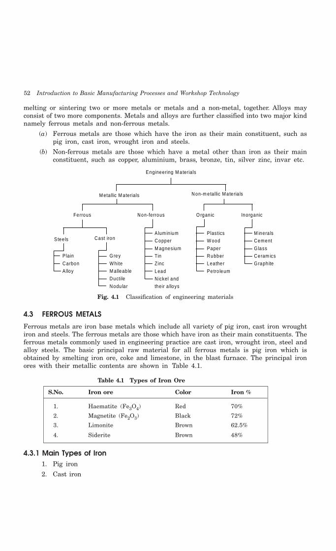
52 Introduction to Basic Manufacturing Processes and Workshop Technology
melting or sintering two or more metals or metals and a non-metal, together. Alloys mayconsist of two more components. Metals and alloys are further classified into two major kindnamely ferrous metals and non-ferrous metals.
(a) Ferrous metals are those which have the iron as their main constituent, such aspig iron, cast iron, wrought iron and steels.
(b) Non-ferrous metals are those which have a metal other than iron as their mainconstituent, such as copper, aluminium, brass, bronze, tin, silver zinc, invar etc.
Engineering M aterials
M etallic M aterials Non-m etallic Materia ls
Ferrous Non-ferrous O rgan ic Inorganic
Stee ls Cast iron
Plain
Carbon
Alloy
G rey
W hite
M alleab le
Ductile
Nodu la r
A lum in ium
Copper
M agnesium
Tin
Zinc
Lead
N ickel and
their a lloys
Plastics
W ood
Paper
Rubber
Leather
Petro leum
M inera ls
Cement
G lass
Ceram ics
G raph ite
Fig. 4.1 Classification of engineering materials
4.3 FERROUS METALS
Ferrous metals are iron base metals which include all variety of pig iron, cast iron wroughtiron and steels. The ferrous metals are those which have iron as their main constituents. Theferrous metals commonly used in engineering practice are cast iron, wrought iron, steel andalloy steels. The basic principal raw material for all ferrous metals is pig iron which isobtained by smelting iron ore, coke and limestone, in the blast furnace. The principal ironores with their metallic contents are shown in Table 4.1.
Table 4.1 Types of Iron Ore
S.No. Iron ore Color Iron %
1. Haematite (Fe3O4) Red 70%
2. Magnetite (Fe2O3) Black 72%
3. Limonite Brown 62.5%
4. Siderite Brown 48%
4.3.1 Main Types of Iron1. Pig iron
2. Cast iron

Ferrous Materials 53
(A) White cast iron
(B) Gray cast iron
(C) Malleable cast iron
(D) Ductile cast iron
(E) Meehanite cast iron
(F) Alloy cast iron
3. Wrought iron
4. Steel
(A) Plain carbon steels
1. Dead Carbon steels
2. Low Carbon steels
3. Medium Carbon steels
4. High Carbon steels
(B) Alloy steels
1. High speed steel
2. Stainless steel
Some important ferrous metals, their extraction, composition, properties and their commonapplications are discussed in detail as under.
4.3.2 Pig IronPig iron was originated in the early days by reduction or iron ores in blast furnace and whenthe total output of the blast furnace was sand cast into pigs which is a mass of iron roughlyresembling a reclining pig. It is roughly of 20" × 9" × 4" in size. It is produced in a blastfurnace and is the first product in the process of converting iron ore into useful ferrous metal.The iron ore on initial refining and heating in blast furnace becomes pig iron when theimpurities are burnt out in a blast furnace. Pig iron acts as the raw material for productionof all kinds of cast iron and steel products. It is obtained by smelting (chemical reduction ofiron ore in the blast furnace. It is of great importance in the foundry and in steel makingprocesses. It is partly refined in a cupola furnace that produces various grades of cast iron.By puddling processes, wrought iron is produced from pig iron. Steel is produced from pig ironby various steel making processes such as bessemer, open-hearth, oxygen, electric and spraysteel making. The charge in the blast furnace for manufacturing pig iron is
(a) Ore Consisting of iron oxide or carbonate associated with earth impurities.
(b) Coke A fuel
(c) Limestone A flux
In addition to iron, pig iron contains various other constituents in varying form ofimpurity such carbon, silicon, sulphur, manganese and phosphorus etc. It has the followingapproximate composition which is as given as under.
Carbon — 4 to 4.5% Phosphorus — 0.1 to 2.0%
Silicon — 0.4 to 2.0% Sulphur — 0.4 to 1.0%
Manganese — 0.2 to 1.5 % Iron — Remainder

54 Introduction to Basic Manufacturing Processes and Workshop Technology
Carbon exists in iron in free form (graphite) and/or in combined form (cementite andpearlite). Pig iron is classified on the basis of contents of free and combined carbon as follows.These classifications are also termed as grades.
1. Grey pig iron (Grades 1, 2 and 3)Grey pig iron contains about 3% carbon in free form (i.e., graphite form) and about 1%
carbon in combined form. This is a soft type of pig iron.
2. White pig iron (Grades 4)White pig iron is hard and strong. It contains almost all of the carbon in the combined
form.
3. Mottled pig iron (Grade 5)This type of pig iron is in between the grey and white variety. It has an average hardness
and molted appearance. The free and combined forms of carbon are in almost equal proportionin mottled pig iron.
4.3.3 Cast IronCast iron is basically an alloy of iron and carbon and is obtained by re-melting pig iron withcoke, limestone and steel scrap in a furnace known as cupola. The carbon content in cast ironvaries from 1.7% to 6.67%. It also contains small amounts of silicon, manganese, phosphorusand sulphur in form of impurities elements.
4.3.3.1 General properties of cast ironCast iron is very brittle and weak in tension and therefore it cannot be used for making
bolts and machine parts which are liable to tension. Since the cast iron is a brittle materialand therefore, it cannot be used in those parts of machines which are subjected to shocks.It has low cost, good casting characteristics, high compressive strength, high wear resistanceand excellent machinability. These properties make it a valuable material for engineeringpurposes. Its tensile strength varies from 100 to 200 MPa, compressive strength from 400 to1000 MPa and shear strength is 120 MPa. The compressive strength of cast iron is muchgreater than the tensile strength. The carbon in cast iron is present either of the followingtwo forms:
1. Free carbon or graphite.
2. Combined carbon or cementite.
The cast iron is classified into seven major kinds as follows:
(a) Grey cast iron, (b) White cast iron, (c) Mottled cast iron (d) Malleable cast iron, (e)Nodular cast iron, (f) Meehanite cast iron. (g) Alloy cast iron and The chemical composition,extraction, properties and general applications of these types of cast iron are discussed asunder.
4.3.3.2 Grey cast ironGrey cast iron is grey in color which is due to the carbon being principally in the form
of graphite (C in free form in iron). It contains:
C = 2.5 to 3.8%.
Si = 1.1 to 2.8 %
Ferrous Materials 55
Mn = 0.4 to 1.0%
P = less than 0.15%
S = less than 0.1%
Fe = Remaining
It is produced in cupola furnace by refining or pig iron.
Properties(i) When fractured it gives grey color.
(ii) It can be easily cast.
(iii) It is marked by presence of flakes of graphite in a matrix of ferrite and pearlite oraustenite; graphite flakes occupy 10% of metal volume.
(iv) It can be easily machined and possesses machinability better than steel.
(v) It possesses lowest melting of ferrous alloys.
(vi) It possesses high vibration damping capacity.
(vii) It has high resistance to wear.
(viii) It possesses high fluidity and hence can be cast into complex shapes and thinsections.
(ix) It possesses high compressive strength.
(x) It has a low tensile strength.
(xi) It has very low ductility and low impact strength as compared with steel.
ApplicationsThe grey iron castings are mainly used for machine tool bodies, automotive cylinder
blocks, pipes and pipe fittings and agricultural implements. The other applications involvedare
(i) Machine tool structures such as bed, frames, column etc.
(ii) Household appliances etc.
(iii) Gas or water pipes for under ground purposes.
(iv) Man holes covers.
(v) Piston rings.
(vi) Rolling mill and general machinery parts.
(vii) Cylinder blocks and heads for I.C. engines.
(viii) Frames of electric motor.
(ix) Ingot mould. And
(x) General machinery parts.
(xi) Sanitary wares.
(xii) Tunnel segment.
4.3.3.3 White cast ironThe white color is due to the fact that the carbon is this iron is in combined form as iron
carbide which is commonly specified as cementite. It is the hardest constituent of iron. It is
56 Introduction to Basic Manufacturing Processes and Workshop Technology
produced in cupola furnace by refining or pig iron. The white cast iron may be produced bycasting against metal chills or by regulating analysis. The chills are used when a hard andwear resistance surface is desired for products such as for wheels, rolls crushing jaw, crusherplates. The chemical composition of white cast iron is given as under.
C = 3.2 to 3.6%
Si = 0.4 to 1.1 %
Mg = 0.1 to 0.4%
P = less than 0.3%
S = less than 0.2%
Fe = Remaining
Properties(i) Its name is due to the fact that its freshly broken surface shows a bright white
fracture.
(ii) It is very hard due to carbon chemically bonded with iron as iron carbide (Fe3C),which is brittle also.
(iii) It possesses excellent abrasive wear resistance.
(iv) Since it is extremely hard, therefore it is very difficult to machine.
(v) Its solidification range is 2650-2065°F.
(vi) Shrinkage is 1/8 inch per foot.
(vii) The white cast iron has a high tensile strength and a low compressive strength.
Applications(i) For producing malleable iron castings.
(ii) For manufacturing those component or parts which require a hard, and abrasionresistant surface such as rim of car.
(iii) Railway brake blocks.
4.3.3.4 Ductile cast ironWhen small quantities of magnesium or cerium is added to cast iron, then graphite
content is converted into nodular or spheroidal form and it is well dispersed throughout thematerial. The resulting structure possesses properties more like cast steel than like the othergrades of cast iron. A typical structure of spheroidal cast iron is shown in Fig. 4.2. Graphiteis in spheroidal form instead of in flaky form. Its structure may be modified by alloys or heattreatment, as in steel to produce austenite, acicular, martensite, pearlite, and ferrite structure.Compositions of ductile cast iron are as follows:
Carbon = 3.2 to 4.2%
Silicon = 1.0 to 4.0 %
Magnesium = 0.1 to 0.8%
Nickel = 0.0 to 3.5%
Manganese = 0.5 to 0.1%
Iron = Remaining

Ferrous Materials 57
Fig. 4.2 Typical structure of spheroidal cast iron
Silicon is also used as an alloying element since it has no effect on size and distributionof carbon content. The magnesium controls the formation of graphite. But it has little influenceon the matrix structure. Nickel and manganese impart strength and ductility. Ductile castiron has high fluidity, excellent castability, strength, high toughness, excellent wear resistance,pressure tightness, weldability and higher machinability in comparison to grey cast iron.
4.3.3.5 Malleable cast ironThe ordinary cast iron is very hard and brittle. Malleable cast iron is unsuitable for
articles which are thin, light and subjected to shock. It can be flattened under pressure byforging and rolling. It is an alloy in which all combined carbon changed to free form bysuitable heat treatment. Graphite originally present in iron in the form of flakes which is thesource of weakness and brittleness. Carbon in this cast iron is dispersed as tiny specks insteadof being flaky or in combined form. The tiny specks have not such weakening effect andcasting would not break when dropped. The tensile strength of this cast iron is usually higherthan that of grey cast iron. It has excellent machining quality and is used for making machineparts for which the steel forging and in which the metal should have a fair degree ofmachining accuracy e.g., hubs of wagon, heels small fittings for railway rolling brake supports,parts of agricultural machinery, pipe fittings, hinges, locks etc.
It can be obtained by annealing the castings. The cast iron castings are packed in anoxidizing material such as iron ore or in an inert material such as ground fire clay dependsupon the process used either white heart or black heart. The packed casting is put into anoven and is heated around 900°C temperature and is kept at that temperature for about twodays and it is then allowed to cool slowly in the furnace itself. Iron ore acting as an oxidizingagent reacts with C and CO2 escape. Thus annealed cast product is free from carbon. If thecastings are packed in an inert material then slow cooling will separate out the combinedcarbon to temper carbon. To produce malleable casting, first casting is produced which hasall combined carbon. The produced castings are then heat-treated in a special manner accordingto white heart method or black heart method.
White heart malleable iron castingThe castings taken out of the mould are put into a drum having sand and powdered slag.
The drum is then closed and kept in the air furnace and it is raised to highly temperatureslowly. The temperature is raised to 920°C in two days time, kept at this temperature fornearly up to 50 to 80 hours then the drum is allowed to cool in the furnace (generally airfurnaces) at the rate 5 to 10°C per hour till it reaches to room temperature. The whole cycletakes about one weak. During this treatment combined carbon separates out and all the

58 Introduction to Basic Manufacturing Processes and Workshop Technology
carbon does not change into graphite state but change in other form of free carbon calledtempered carbon.
Fe3C ——→ 3Fe + C
This makes the casting less brittle and malleable. The fracture portion of such a castingis dark grey or black in appearance. These castings are specially used in automobile industries.
Black heart malleable iron castingThe castings packed in a drum of oxidizing media which is generally powdered iron ore
or powered scale (film of Fe3O4 on surface). This close drum is kept in the furnace and heatedto 900°C. It is then maintained at this temperature to nearly 40 to 70 hours and allowed tocool slowly in a furnace itself. The castings become malleable like white heart cast iron. Thepercentage of carbon and silicon should be so selected that it can promote the developmentof free carbon when these castings are annealed.
Properties1. Malleable cast iron is like steel than cast iron.
2. It is costly than grey cast iron and cheaper than softer steel.
ApplicationsMalleable cast iron are generally used to form automobile parts, agriculture
implementation, hinges, door keys, spanners mountings of all sorts, seat wheels, cranks,levers thin, waned components of sewing machines and textiles machine parts.
4.3.3.6 Meehanite cast ironMeehanite cast iron is an inoculated iron of a specially made white cast iron. The
composition of this cast iron is graphitized in the ladle with calcium silicide. There are varioustypes of meehanite cast iron namely heat resisting, wear resisting and corrosion resistingkind. These materials have high strength, toughness, ductility and good machinability. It ishighly useful for making castings requiring high temperature applications.
4.3.3.7 Alloy cast ironThe cast irons as discussed above contain small percentages of other constituents like
silicon, manganese, sulphur and phosphorus. These cast irons may be called as plain castirons. The alloy cast iron is produced by adding alloying elements like nickel, chromium,molybdenum, copper and manganese in sufficient quantities in the molten metal collected inladles from cupola furnace. These alloying elements give more strength and result inimprovement of properties. The alloy cast iron has special properties like increased strength,high wear resistance, corrosion resistance or heat resistance. The alloy cast irons areextensively used for automobile parts like cylinders, pistons, piston rings, crank cases, brakedrums, parts of .crushing and grinding machinery etc.
4.3.3.8 Effect of impurities on cast ironThe cast iron contains small percentages of carbon, silicon, sulphur, manganese and
phosphorus. The affect of these impurities on the cast iron are as follows:
(1) Carbon. Carbon is one of the important elements in cast iron. It reduces meltingpoint of iron. Pure iron has a melting point of about 1500°C but iron with 3.50% Chas melting point of about 1350°C. When carbon is in free form i.e. as graphite form,

Ferrous Materials 59
the resulting cast iron is known grey cast iron. On the other hand, when the ironand carbon are chemically combined form of cementite, the cast iron will be hardand known as white cast iron.
(2) Silicon. Presence of silicon in cast iron promotes the decomposition of cementiteinto graphite. It also helps to reduce the shrinkage in cast iron when carbon ischanged to graphite forms.
(3) Sulphur. It makes the cast iron hard and brittle. Since too much sulphur givesunsound casting, therefore, it should be kept below 0.1% for most casting purposes.It is often responsible for creating troubles to foundry men. It will make cast ironhard thereby counteracting the softening influences of silicon. It decreases strengthand increases brittleness. It also promotes oxidation of cast iron. Hence, it is keptas low as possible in cast iron.
(4) Manganese. It makes cast iron white and hard. It is often kept below 0.75%. Ithelps to exert a controlling influence over the harmful effect of sulphur. It reducesthe harmful effects of the sulphur by forming the manganese sulphide which is notsoluble in cast iron.
(5) Phosphorus. It increases fusibility and fluidity in cast iron but induces brittleness.It is rarely allowed to exceed 1 %. Phosphorus in irons is useful for casting ofintricate shapes and for producing very cheap and light engineering castings.Phosphorus has no effect on the carbon as well as on shrinkage in the cast iron.
4.3.3.9 Comparison among grey, white and spherodidal cast ironThe comparison among grey, white and spherodidal cast iron is given in Table 4.2.
TABLE 4.2 Comparison among Grey, White and Spherodidal Cast Iron
S.No Grey Cast Iron White Cast Iron Spherodidal Cast Iron
1. It is an alloy of carbon andsilicon with iron having greycolor when fractured. It ismarked by the presence offlakes of matrix of ferrite,pearlite or austenite.Carbon in iron exists in freeform as graphite
White cast iron has almostall its carbon as iron carbide.Its broken surface shows abright white fracture.
Graphite appears as aroundParticles or spheroids.
2 It has good machinability,high resistance to wear,high vibration dampingcapacity and highcompressive strength.
It has poor machinability,excellent abrasive wearresistance.
It has good machinability, gooddamping, excellent castabilityand sufficient wear resistance
3 It is used in machine toolstructure, Main-hole covers,cylinder blocks, heads forI.C. engines, gas or waterpipes for undergroundpurposes, frames forelectric motors, pistonrings and sanitary wares.
It is used for producingmalleable iron castings andmanufacturing thosestructural component partswhich require a hard andabrasion resistant material.
It is used in I.C. engines, paperIndustry machinery, machinery forfarming and tractor, application,earth moving machinery, valveand fittings, pipes, pumps,compressors and constructionmachinery.
60 Introduction to Basic Manufacturing Processes and Workshop Technology
4.3.4 Wrought IronWrought iron is the assumed approximately as purest iron which possesses at least 99.5%iron. It contains a large number of minute threads of slag lying parallel to each other, therebygiving the metal a fibrous appearance when broken. It is said as a mechanical mixture of verypure iron and a silicate slag. It can also be said as a ferrous material, aggregated from asolidifying mass of pasty particles of highly refined metallic iron with which a minutely anduniformly distributed quantity of slag is incorporated without subsequent fusion. This iron isproduced from pig iron by re-melting it in the puddling furnace or air furnace or reverberatoryfurnace. The molten metal free from impurities is removed from the furnace as a pasty massof iron and slag. The balls of this pasty mass, each about 45 to 65 kg in weight, are formed.These balls are then mechanically worked to squeeze out the slag and to form it into somecommercial shape. This iron contains practically no carbon and therefore can not be hardened.
Chemical CompositionA chemical composition range of typical wrought iron includes:
C = 0.02 – 0.03% P = 0.05 – 0.25% Si = 0.02 – 0.10%
S = 0.008 – 0.02% Mn = 0.0 – 0.02% Slag = 0.05 – 1.5%
Fe = remainder
PropertiesThe wrought iron can be easily shaped by hammering, pressing, forging, etc. It is never
cast and it can be easily bent when cold. It is tough and it has high ductility and plasticitywith which it can be forged and welded easily. Its ultimate strength can be increased considerablyby cold working followed by a period of aging. It possesses a high resistance towards corrosion.It can accommodate sudden and excessive shocks loads without permanent injury. It has ahigh resistance towards fatigue. Its ultimate tensile strength is 2,500 kg/cm2 to 5,000 kg/cm2
and the ultimate compressive strength is 3,000 kg/cm2. It can be elongated considerably bycold working. It has high electrical conductivity. The melting point of wrought iron is about1530°C. It has elongation 20% in 200 mm in longitudinal direction and 2–5 % in transversedirection. Its poison’s ratio is 0.30. It can be easily formed when cold, without the outer sidecracking at the formed portion.
ApplicationsIt is used for making chains, crane hooks, railway couplings, and water and steam pipes.
It has application in the form of plates, sheets, bars, structural works, forging blooms andbillets, rivets, and a wide range of tubular products including pipe, tubing and casing, electricalconduit, cold drawn tubing, nipples and welding fittings, bridge railings, blast plates, drainagelines and troughs, sewer outfall lines, weir plates, sludge tanks and lines, condenser tubes,unfired heat exchangers, acid and alkali process lines, skimmer bars, diesel exhaust and airbrake piping, gas collection hoods, coal equipment, cooling tower and spray pond piping.
4.3.5 SteelsSteel is an alloy of iron and carbon with carbon content maximum up to 1.7%. The carbonoccurs in the form of iron carbide, because of its ability to increase the hardness and strengthof the steel. The effect of carbon on properties of steel is given in Fig. 4.3. Other elementse.g. silicon, sulphur, phosphorus and manganese are also present to greater or lesser amountto import certain desired properties to it. Most of the steel produced now-a-days is plain

Ferrous Materials 61
carbon steel. Carbon steel has its properties mainly due to carbon content and does notcontain more than 0.5% of silicon and 1.5% of manganese.
300
200
100
60
50
40
30
20
100
50
Ulti
mat
e S
tren
gth
Brin
ell H
ardn
ess
Cem
entit
e
U ltimate Stre
ngth
Brine ll H ardness
Ductility
Pea
rlite
%
Fer
rite
Ca rbon %
Low
Pea
rlite
%
0 0 .2 0 .4 0 .6 0 .8 1 .0 1 .2
Fig. 4.3 Effect of carbon on properties of steel
For checking microstructure of steel, its specimen is prepared by preparing a flat mirrorsurface on small piece of metal through rubbing by sand papers, polishing and buffing etc.This surface is then followed by etching with a chemical solution. The chemical solutionreacts with various constituents in varying degree to reveal crystal structure clearly. Therevealed structure is then viewed through powerful microscope. The viewed micro structuresfor different steel are depicted in Fig. 4.4.
Pearlite
FerriteG ra in
(a )
Ferrite(0 .3% C)
(b)
Ferrite(6 .6% C)
(c)
Pearlite(0 .83% C)
(d)
Cementite(1 .0% C)
(e)
Pearlite Pearlite
Fig. 4.4 Micro structure of steel
4.3.5.1 Effect of impurities on steelThe effects of impurities like silicon, sulphur, manganese and phosphorus, on steel as
discussed under.
1. Silicon. Silicon content in the finished steel usually ranges from 0.05 to 0.30%. Itis added in low carbon steels for preventing them from becoming porous. It helpsin removing the gases and oxides. It prevents blow holes there by making steeltougher and harder.

62 Introduction to Basic Manufacturing Processes and Workshop Technology
2. Sulphur. It renders free cutting properties in steel. It is found in steel either asiron sulphide or manganese sulphide. Iron sulphide due to its low melting point,produces brittleness whereas manganese sulphide does not affect so much. Therefore,manganese sulphide is less objectionable in steel than iron sulphide.
3. Manganese. It serves as a valuable deoxidizing and purifying agent, in steel.Manganese also combines with sulphur and thereby decreases the harmful effect ofthis element remaining in the steel. It increases wear resistance, hardness andstrength and decreases machineability. When used in ordinary low carbon steels,manganese makes the metal ductile and of good bending quantities. In high speedsteels, it is used to tougher the metal and to increase its critical temperature.
4. Phosphorus. It induces brittleness in steel. It also produces cold shortness in steel.In low carbon steels, it raises the yield point and improves the resistance to atmosphericcorrosion. The sum of carbon and phosphorus usually does not exceed 0.25%.
To produce needed improvement in properties of plain carbon steel, certain elements insteel are alloyed for specific purposes to increase wearing resistance, electrical and mechanicalproperties which cannot be obtained in plain carbon steels.
The steel may be of various kinds and few important types are explained as under.
4.3.5.2 Plain carbon steelPlain carbon steel is an alloy of iron and carbon. It has good machineability and malleability.
It is different from cast iron as regards the percentage of carbon. It contains carbon from 0.06to 1.5% whereas cast iron possesses carbon from 1.8 to 4.2%. Depending upon the carboncontent, a plain carbon steels can divided to the following types:
1. Dead carbon steel — up to 0.15% carbon
2. Low carbon or mild steel — 0.15% to 0.45% carbon
3. Medium carbon steel — 0.45% to 0.8% carbon
4. High carbon steel — 0.8% to 1.5% carbon
Each type is discussed as under.
DEAD CARBON STEELIt possesses very low percentage of carbon varying from 0.05 to 0.15%. It has a tensile
strength of 390 N/mm2 and a hardness of about 115 BHN. Steel wire, sheets, rivets, screws,pipe, nail and chain are made from this steel. This steel is used for making camshafts, sheetsand strips for fan blades, welded tubing, forgings, chains, stamping, rivets, nails, pipes,automobile body etc.
LOW CARBON OR MILD STEELLow carbon steel is sometimes known as mild steel also. It contains 0.20 to 0.30% C
which has tensile strength of 555 N/mm2 and hardness of 140 BHN. It possesses brightfibrous structure. It is tough, malleable, ductile and more elastic than wrought iron. It canbe easily forged and welded. It can absorb shocks. It rusts easily. Its melting point is about1410°C. It is used for making angle, channels, case hardening steel, rods, tubes, valves, gears,crankshafts, connecting rods, railway axles, fish plates, small forgings, free cutting steel shaftand forged components etc.
Ferrous Materials 63
Applications1. Mild steel containing 0.15 to 0.20% carbon
It is used in structure steels, universal beams, screws, drop forgings, case hardeningsteel, bars, rods, tubes, angles and channels etc.
2. Mild steel containing 0.20-0.30% carbon
It is used in making machine structure, gears, free cutting steels, shafts and forgedcomponents etc.
MEDIUM CARBON STEELSMedium carbon steel contains carbon from 0.30 to 0.8%. It possesses having bright
fibrous structure when fractured. It is tough and more elastic in comparison to wrought iron.It can be easily forged, welded, elongated due to ductility and beaten into sheets due to itsgood malleability. It can easily absorb sudden shocks. It is usually produced as killed or semikilled steels and is harden able by treatment. Hardenability is limited to thin sections or tothe thin outer layer on thick parts. Its tensile strength is better than cast iron and wroughtiron but compressive strength is better than wrought iron but lesser than cast iron. It rustsreadily. Its melting point is 1400°C. It can be easily hardened and it possesses good balanceof strength and ductility.
It is generally used for making railway coach axles, bolts, connecting rods, key stock,wires and rods, shift and break levers, spring clips, gear shafts, small and medium forgings,railway coach axles, crank pins on heavy machines, spline shafts, crankshafts, forging dies,set screws, die blocks, self tapping screws, clutch discs, valve springs, plate punches, thrustwashers etc. The applications of different kinds of medium carbon steel are given as under.
Applications1. Plain carbon steels having carbon % 0.30 to 0.45. Axles, special duty shafts,
connecting rods, forgings, machinery steel, spring clips, turbine, rotors, gear shafts,key stock, forks and bolts.
2. Plain carbon steels having carbon % 0.45 to 0.60. Railway coach axles, crankpins, crankshafts, axles, spline shafts, loco tyres.
3. Plain carbon steels having carbon % 0.60 to 0.80. Drop forging dies, die blocks,bolt heading dies, self-tapping screws, valve spring, lock washers, hammers, coldchisels, hacksaws, jaws for vices etc.
HIGH CARBON STEELSHigh carbon steels (HCS) contain carbon from 0.8 to 1.5%. Because of their high hardness,
these are suitable for wear resistant parts. Spring steel is also high carbon steel. It isavailable in annealed and pre-tempered strips and wires. High carbon steel loses their hardnessat temperature from 200°C to 250°C. They may only be used in the manufacture of cuttingtools operating at low cutting speeds. These steels are easy to forge and simple to harden.These steels are of various types which are identified by the carbon percentage, hardness andapplications
HCS containing 0.7 to 0.8% carbon possesses hardness of 450-500 BHN. It has applicationfor making cold chisels, drill bits, wrenches, wheels for railway service, jaws for vises,structural wires, shear blades, automatic clutch discs, hacksaws etc.

64 Introduction to Basic Manufacturing Processes and Workshop Technology
Steel containing 0.8 to 0.9% C possesses hardness of 500 to 600 BHN. This steel isused for making rock drills, punches, dies, railway rails clutch discs, circular saws, leafsprings, machine chisels, music wires,
Steel containing 0.90 to 1.00% carbon is also known as high carbon tool steel and itpossesses hardness of 550-600 BHN. Such steel is used for making punches, dies, springs keysand shear blades.
Steel containing 1.0 to 1.1 % C is used for making railway springs, mandrels, taps,balls, pins, tools, thread metal dies.
Steel containing 1.1 to 1.2% C is used for making taps, twist drills, thread dies, knives.
Steel containing 1.2 to 1.3% carbon is used for making files, reamers Files, dies forwire drawing, broaches, saws for cutting steel, tools for turning chilled iron.
Cutting tool materials imply the materials from which various lathe tools or othercutting tools are made. The best tool material to use for a certain job is the one that willproduce the machined part at the lowest cost. To perform good during cutting, the toolmaterial should possess the following properties for its proper functioning.
1. A low coefficient of friction between tool material and chip material.
2. Ability to resist softening at high temperature.
3. Ability to absorb shocks without permanent deformation.
4. Sufficient toughness to resist fracture and bear cutting stresses.
5. Strength to resist disintegration of fine cutting edge and also to withstand thestresses developed, during cutting, in the weakest part of the tool.
6. High hardness that means tool must be harder than the material being cut.
According to Indian standard IS 1570-1961, plain carbon steels are designated by thealphabet ‘C’ followed by numerals which indicate the average percentage of carbon in it. Forexample C40 means a plain carbon steel containing 0.35% to 0.45% C (0.40% on average),although other elements like manganese may be present. In addition to the percentage ofcarbon, some other specification may include e.g. C55Mn75 means the carbon content liesbetween 0.50% to 0.60% and the manganese content lies between 0.60 to 0.90%. It may benoted that only average contents are specified in such designation of steel.
4.3.5.3 Alloy steelFor improving the properties of ordinary steel, certain alloying elements are added in it
in sufficient amounts. The most common alloying elements added to steel are chromium,nickel, manganese, silicon, vanadium, molybdenum, tungsten, phosphorus, copper, that thetitanium, zirconium, cobalt, columbium, and aluminium. Each of these elements inducescertain qualities in steels to which it is added. They may be used separately or in combinationto produce desired characteristics in the steel. The main purpose of alloying element in steelis to improve machinability, elasticity, hardness, case hardening, cutting ability, toughness,wear resistance, tensile strength, corrosion resistance, and ability to retain shape at hightemperature, ability to resist distortion at elevated temperature and to impart a fine grainsize to steel. Like carbon, a number of alloying elements are soluble to produce alloys withimproved strength, ductility, and toughness. Also carbon, besides forming an inter-metalliccompound with iron, combines with many alloying elements and form alloy carbides. Thesealloy carbides as well as iron-alloy carbides are usually hard and lack in toughness. Some

Ferrous Materials 65
alloying elements are added to prevent or restrict grain growth. Aluminium is considered themost effective in this respect. Others are zirconium, vanadium, chromium, and titanium. Theaddition of alloying elements almost always affects the austenite-ferrite transformationmechanism. Some alloying elements lower and some raise the critical temperature. Thecompositional and structural changes produced by alloying elements change and improve thephysical, mechanical and processing properties of steel.
4.3.5.4 Effect of alloying elements in steelThe chief alloying elements used in steel are nickel, chromium, molybdenum, cobalt,
vanadium, manganese, silicon and tungsten. Each of these elements possesses certain qualitiesupon the steel to which it is added. These elements may be used separately or in combinationto produce the desired characteristic in steel. Following are the effects of alloying elementson steel.
1. Nickel. Steels contain 2 to 5% nickel and from 0.1 to 0.5% carbon increase itsstrength and toughness. In this range, nickel contributes great tensile strength,yield strength, toughness and forming properties and hardness with high elasticlimit, good ductility and good resistance to corrosion. An alloy containing 25% nickelpossesses maximum toughness and offers the greatest resistance to rusting, corrosionand burning at high temperature. It has proved beneficial in the manufacture ofboiler tubes, valves for use with superheated steam, valves for I.C. engines andsparking plugs for petrol engines. A nickel steel alloy containing 36% of nickel isknown as invar. It has nearly zero coefficient of expansion. Therefore, it is in greatdemand for making measuring instruments for everyday use.
2. Chromium. It improves corrosion resistance (about 12 to 18% addition). It increasestensile strength, hardness, wear resistance and heat resistance. It provides stainlessproperty in steel. It decreases malleability of steel. It is used in steels as an alloyingelement to combine hardness with high strength and high elastic limit. It alsoimparts corrosion resisting properties to steel. The most common chrome steelscontain from 0.5 to 2% chromium and 0.1 to 1.5% carbon. The chrome steel is usedfor balls, rollers and races for bearings. A Nickel-Chrome steel containing 3.25%nickel, 1.5% chromium and 0.25% carbon is much used for armour plates. Chromenickel steel is extensively used for motor car crank shafts, axles and gears requiringgreat strength and hardness.
3. Tungsten. It increases hardness, wear resistance, shocks resistance and magneticreluctance. It increases ability to retain hardness and toughness at high temperature.It prohibits grain growth and increases wear resistance, shock resistance, toughness,and the depth of hardening of quenched steel. The principal uses of tungsten steelsare for cutting tools, dies, valves, taps and permanent magnets.
4. Vanadium. It improves tensile strength, elastic limit, ductility, fatigue resistance,shock resistance and response to heat treatment. It also acts as a degasser whenadded to molten metal. It aids in obtaining a fine grain structure in tool steel. Theaddition of a very small amount of vanadium (less than 0.2%) produces a markedincrease in tensile strength and elastic limit in low and medium carbon steels withouta loss of ductility. The chrome- vanadium steel containing about 0.5 to 1.5% chromium,0.15 to 0.3% vanadium and 0.13 to 1.1% carbon have extremely good tensile strength,elastic limit, endurance limit and ductility. These steels are frequently used for partssuch as springs, shafts, gears, pins and many drop forged parts.

66 Introduction to Basic Manufacturing Processes and Workshop Technology
5. Molybdenum. A very small quantity (0.15 to 0.30%) of molybdenum is generallyused with chromium and manganese (0.5 to 0.8%) to make molybdenum steel. Itincreases hardness, wear resistance, thermal resistance. When added with nickel,it improves corrosion resistance. It counteracts tendency towards temper brittleness.It makes steel tough at various hardness levels. It acts as a grain growth inhibitorwhen steels are heated to high temperatures. Molybdenum steels possesses hardness,wear resistance, thermal resistance and extra tensile strength. It is used for air-plane fuselage and automobile parts. It can replace tungsten in high speed steels.
6. Cobalt. When added to steel, it refines the graphite and pearlite and acts as a grainrefiner. It improves hardness, toughness, tensile strength and thermal resistance.
7. Titanium. It acts as a good deoxidizer and promotes grain growth. It preventsformation of austenite in high chromium steels. It is the strongest carbide former.It is used to fix carbon in stainless steels and thus prevents the precipitation ofchromium carbide.
8. Aluminium. It is used as a deoxidizer. If present in an amount of about 1 %, ithelps promoting nitriding.
9. Copper. It improves resistance to corrosion. It increases strength. More than 0.6per cent copper for precipitation.
10. Silicon. It improves magnetic permeability and decreases hysteresis losses. Itdecreases weldability and forgeability. It is also added as a deoxidizer during castingof ingots. It takes care of oxygen present in steel by forming SiO2. Silicon steelsbehave like nickel steels. These steels have a high elastic limit as compared toordinary carbon steel. Silicon steels containing from 1 to 2% silicon and 0.1 to 0.4%carbon and other alloying elements are used for electrical machinery, valves in I.C.engines, springs and corrosion resisting materials.
11. Manganese. It improves the strength of the steel in both the hot rolled and heattreated condition. The manganese alloy steels containing over 1.5% manganese witha carbon range of 0.40 to 0.55% are used extensively in gears, axles, shafts andother parts where high strength combined with fair ductility is required. The principaluse of manganese steel is in machinery parts subjected to severe wear. These steelsare all cast and ground to finish.
12. Carbon. It increases tensile strength and hardness. It decreases ductility andweldability. It affects the melting point.
4.3.5.5 Free cutting steelThe important features of free cutting steels are their high machinability and high
quality surface finish after finishing. These properties are due to higher sulphur and phosphorus.Sulphur exists in the form of manganese sulphide (MnS) which forms inclusions in steel.These inclusions promote the formation of discontinuous chips and also reduce friction on thesurface being machined so produces good surface finish easily. Phosphorus is dissolved in theferrite and increases hardness and brittleness. Lead up to 0.35% can be added to improve themachinability of steel. These have high sulphur content present in form of manganese sulphideinclusions causing the chips to break short on machining. Mn and P make steel hardened andbrittle. Lead (0.2% to 0.35%) is sometimes added to steel improving machinability propertiesof steel. This consists of three Bessemer grades B1111, B1112, B1113 which differ in sulphurcontent and the sulphurised steels from C1108 to C1151. The tool life achieved in machining
Ferrous Materials 67
free cutting steels is from 2 to 2.5 times higher than when carbon steels of the same carboncontent. However, it must be noted that free cutting steels have lower dynamic strengthcharacteristics and are more susceptible to corrosion. Free cutting steels are frequentlysupplied in the cold drawn or work hardened form. These cold drawn steels have a hightensile strength and hardness but less ductile when compared to other kind of steels.
Applications of free cutting steelThese steels are used for manufacturing axles, bolts, screws, nuts, special duty shafts,
connecting rods, small and medium forgings, cold upset wires and rods, solid turbine rotors,rotor and gear shaft, armature, key stock, forks and anchor bolts screw stock, spring clips,tubing, pipes, light weight rails, concrete reinforcing etc.
4.3.5.6 Nickel steelThe percentage of Nickel varies from 2 to 45 in steel. Steel having 2% Ni makes steel
more suitable for rivets, boiler plates, bolts and gears etc. Steel having Ni from 0.3 to 5%raises elastic limit and improves toughness. Steel containing Nickel has very high tensilestrength. Steel having 25% Ni makes it stainless and might be used for I.C. engine turbineblade etc. If Ni is present up to 27%, it makes the steel non-magnetic and non-corrodible.Invar (Ni 36%) and super-invar (Ni 31%) are the popular materials for least coefficient ofexpansion and are used for measuring instruments, surveyor tapes and clock pendulums.Steel having 45% Ni steel possesses extension equal to that of glass, a property very importmaking links between the two materials i.e. in electronic valves and bulbs.
4.3.5.7 Vanadium steelVanadium when added even in small proportion to an ordinary low carbon increases
significantly its elastic limit and fatigue resistance property. Vanadium makes steel strong andtough. When vanadium is added up to 0.25%, the elastic limit of the steel is raised by 50%can resist high alternating stresses and severe shocks.
Applications1. It is widely used for making tools.
2. It can also be used for shafts, springs, gears, steering knuckles and drop forgedparts
4.3.5.8 Manganese steelManganese when added in steel between 1.0 to 1.5% makes it stronger and tougher.
Manganese between 1.5 to 5% in steel makes it harder and more brittle. 11 to 14% manganesein steel with carbon 0.8 to 1.5% makes it very hard, tough, non-magnetic and possessesconsiderably high tensile strength. Manganese steel may be forged easily but it is difficult tomachine and hence it is usually ground. It is weldable and for welding it, a nickel manganesewelding rod is used.
Applications1. Because of work hardening, it is suitable for jaws of stone and ore crushers, grinding
plants, tramway and railway points and crossing etc.
2. Manganese steel in the form of bars is now widely used for screening coke.
3. It is also used for helmets and shields.
4. It is used for agricultural implements such as shovels etc.
68 Introduction to Basic Manufacturing Processes and Workshop Technology
4.3.5.9 Tungsten SteelTungsten when added to steel improves its magnetic properties and hardenability. When
tungsten is added to an extent of 6% to high carbon steel, it retains the magnetic propertiesto high degree and produce field more intense than ordinary steel. Steel having 8% tungstengives sufficient hardness to it to scratch even glass.
ApplicationsIt is used for making permanent magnets and high speed cutting tools.
4.3.5.10 Silicon steelSilicon addition improves the electrical properties of steel. It also increases fatigue
strength and ductility.
Applications1. Steel with
Mn = 1 %, Si = 2% and C = 0.4 to 0.6%
has very high elastic limit and is used for springs.
2. Steel containing 5 to 7% silicon
retains its hardness and resistance to oxidation at high temperature. It is used formaking internal combustion engines.
3. Steel possessing 13% Si has a very high corrosion resistance and it can be used inchemical industrial applications.
4. Steel possessing 1% Si and up to 0.95% Mn is suitable for structural purposes.
4.3.5.11 Magnetic steelsSteels having 15 to 40% Co, 0.4 to 1 % C, 1.5 to 9% Cr, 0-10% W and remaining Fe
possesses very good magnetic properties. High Cobalt steels, when correctly heat treated, arefrequently used in the making of permanent magnets for magnetos, loud speakers and otherelectrical machines. An important permanent magnet alloy called Alnico contains approximately60% Iron, 20% Nickel, 8% Cobalt and 12% Aluminium. This alloy cannot be forged and is usedas a casting hardened by precipitation heat treatment.
4.3.5.12 Heat resisting steelsHeat resisting steels are practically suitable for working at even very high temperatures.
Such steels must resist the influences which lead to failure of ordinary steels when put towork under high temperatures. Alloy steel containing 23-30% chromium with less than 0.35%C are mainly used to impart heat resisting service in the temperature range between 815-1150 °C. The furnace parts and annealing boxes are generally made by this steel. These steelsare particularly suitable for working at high temperatures and are thus stable at hightemperatures. A steel containing chromium, nickel and tungsten, with the carbon contentsuitably controlled provide useful combination of non-scaling and strength retaining propertiesat high temperature. Such steels can work satisfactory up to 700°C and contains 0.15% C, 0.5to 2 % Si, 0.5% Mn, 1.0 to 6%, Cr and 0.5%. Mo.
ApplicationsThese are used in nuclear power plant, furnaces, supersonic aircrafts, missiles, annealing
boxes etc.

Ferrous Materials 69
4.3.5.13 Spring steelsSpring steels are used for the making springs. Various types of these steel along with
their composition and uses are discussed as under.
(i) Carbon-manganese spring steels. This type of steel contains
C = 0.45 to 0.6, Si = 0.1 to 0.35% and Mn = 0.5 to 1.0%.
These steels are quenched and tempered up to 350 BHN. They are widely used forlaminated springs for railway and general purposes.
(ii) Hyper-eutectoid spring steels. This type of steel contains
C = 0.9 to 1.2%, 0.3% (max) and Mn = 0.45 to 0.70%.
These steels are oil quenched and tempered at low temperature. This type of steelis used for volute and helical springs.
(iii) Silicon-manganese spring steels. This type of steel contains
C = 0.3 to 0.62%, Si = 1.5 to 2% and Mn = 0.6 to 1 %.
These steels are hardened and tempered. This type of steel is used for themanufacturing of railway and road springs generally.
4.3.5.14 Structural steelsStructural steels possess high strength and toughness, resistance to softening at elevated
temperatures and enough resistance to corrosion. In addition, they should possess weldability,workability and high hardenability. The principal alloying elements in structural steels arechromium, nickel and manganese. These steels has various applications which are given asunder:
ApplicationsThey are used for structural members of bridges, buildings, rail road, cars etc. They are
also used for manufacturing components subjected to static and dynamic loads. Thesecomponents include valves, pins, studs, gears, clutches, bushes, shafts etc.
4.3.5.15 Stainless steelStainless steel contains chromium together with nickel as alloy and rest is iron. It has
been defined as that steel which when correctly heat treated and finished, resists oxidationand corrosive attack from most corrosive media. Stainless steel surface is responsible forcorrosion resistance. Minimum chromium content of 12% is required for the film’s formation,and 18% is sufficient to resist the most severe atmospheric corrosive conditions. Their principalalloying element is chromium while some other elements like nickel, manganese etc. can alsobe present in small amounts. Addition of nickel improves ductility and imparts strength.Corrosion resistance to stainless steels increases with increase in nickel content againstneutral chloride solution and weakly oxidizing acids. Addition of molybdenum improves itsresistance to sulphuric, sulphurous and organic acids. Addition of manganese increases hotworkability of these steels.
Steels having 15 to 20% Ni and about 0.1 % carbon possesses great strength and toughnessand extremely good resistance to corrosion. Such steels are called stainless steels. Another typeof stainless steel containing 11 to 14% chromium and about 0.35% carbon is used for cutlery,surgical and dental instruments and other purposes where hard edges are required. Maximumresistance to corrosion is obtained when this steel is ground and polished after heat-treating.
70 Introduction to Basic Manufacturing Processes and Workshop Technology
A steel containing 18% chromium and 8% nickel is widely used and is commonly referredto as 18/8 steel. Stainless steel is highly resistance to corrosion and oxidation. It can be classifiedinto three major categories according to the type of micro structures.
General Properties of Stainless SteelsIt possesses wide range of strength and hardness, high ductility, formability, high corrosion
resistance, good creep resistance, good thermal conductivity, good machinability, goodweldability, high hot, cold workability, high resistance to scaling and oxidation at elevatedtemperatures, excellent surface appearance and finish.
Classification of Stainless SteelOn basis of their structure, stainless steels are classified as follow:
1. Martensitic stainless steels
2. Ferritic stainless steels
3. Austenitic stainless steels.
These types of stainless steel are discussed as under.
Martensitic Stainless SteelsThese steels contain 12 to 16% chromium and 0.1 to 1.2 per cent carbon. The structure
consists of hard martensite phase after hardening. The general utility chromium stainlesssteel with 12% chromium and 0.15% carbon are ferromagnetic and air hardening. It is veryhard and possesses high strain and high corrosion resistance properties.
ApplicationsStainless steels containing 12 to 14% chromium and 0.3% carbon are extensively used
for table cutlery, tools and equipments etc. Stainless steels containing 16-18% chromium and0.2% carbon are used as springs, ball bearing, valves, knife blades and instruments underhigh temperature and corrosive conditions. These steels are generally used for making utensils,surgical and dental instruments, and springs of high temperature operations, ball valves andtoilet seats.
Ferritic Stainless SteelsFerritic stainless steels are non hardenable and contain 16 to 30% chromium and 0.08
to 0.2 per cent carbon. Structure of these steel consists of ferrite phase which cannot behardened by heat treatment. They have very low carbon and possess considerable ductility,ability to be worked hot or cold, excellent corrosion resistance and are relatively in expensive.They are always magnetic and retain their basic microstructure up to the melting point.
ApplicationsThese are extensively used for kitchen equipment, diary machinery interior decorative
work, automobile trimmings, chemical engineering industry, stainless steel sinks, foodcontainers, refrigerator parts, beer barrels, automobile trimming etc. These are also used ashigh temperature furnace parts when chromium content is high.
Austenitic Stainless SteelAddition of substantial quantities of Ni to high Cr alloys gives rise to, austenitic steel.
It has good resistance to many acids (even hot or cold nitric acid). Slight amount of W andMo are added in such steels to increase its strength at elevated temperatures. This steel
Ferrous Materials 71
contains 16 to 24% Cr, 8 to 22% Ni and less than 0.2% C. Addition of nickel stabilizesaustenite, and hence the structure of these steels consists of austenite at room temperature.A steel containing 18% Cr and 8% Ni is very widely used and is commonly referred to as 18/8 stainless steel. These steels do not harden by heat treatment but can be rolled hard. Thesesteels possess a brilliant luster when polished. These are highly resistant to many acids evennitric acids. The heat conductivity of steel is low, about 5% that of copper. Tungsten andmolybdenum are added to increase the strength at elevated temperatures, silicon and aluminiumto improve the resistance to scaling and selenium and sulphur are added to improvemachinability. This steel is easily weldable. After welding, it is susceptible to corrosive attackin the area adjacent to the weld.
ApplicationsIt is used for making heat exchangers, conveyors chains, furnaces, spokes, brewery, dairy
and chemical industrial components, cutlery parts, surgical and dental instruments, householdappliances such as kitchen utensils, sinks and saucepans. These are also used in makingcomponents in power stations, especially in nuclear power stations, steam pipes, boiler tubes,radiator and super heater tubes.
4.3.5.16 High speed steelsHigh Speed Steels (HSS) have been given this name due to the fact that these steels may
be operated as cutting tools at much higher speeds that are possible with plain carbon toolsteel. High speed steels cutting tools operate at cutting speed 2 to 3 times higher than forHigh carbon steels. At higher cutting speeds, sufficient heat may be developed during thecutting process. This heat causes the cutting edge of the tool to reach a high heat (red heat).This heat softens the carbon tool steel and thus the tool will not work efficiently for a longerperiod. These steels have the property of retaining their hardness even when heated to redheat. High hardness at elevated temperatures is developed by addition of elements such astungsten, chromium vanadium to high carbon steels. These steel are generally used formaking lathe cutting tools, planner cutting tools, shaper cutting tools, slotting cutting tools,drills, reamers, broaches, milling cutter and punches. There are four general types of highspeed steels used in machine shop.
1. High speed steel (18:4:1)High speed steels (HSS) are most commonly operated as cutting tools at much higher
speed i.e. twice or thrice where as tool steel. It is the most common kind of cutting tool. Itcontains 18% tungsten, 4% chromium and 1 % vanadium, 0.8 carbon and remaining iron. Itis considered to be one of the best of all purpose tool steels. This brand of high speed steelis used for machining operations on steel and non-ferrous materials. This is generally usedfor lathe, planer and shaper tools, drills, millings cutters, punches etc.
2. Molybdenum based high speed steelIt contains 6% Mo, 6% W, 4% Cr, 2% V, 0.8% C and remaining Fe. It has excellent
toughness and cutting ability. Molybdenum high speed steels are cheaper than other types ofsteels and are particularly used for drilling and tapping tools. These steels are also used formaking rough cutting tools, lathe tools and various kinds of milling cutters.
3. Cobalt based high speed steelIt contains 1 to 12% Co, 20% W, 4% Cr, 2% V, 0.8 carbon and remaining iron. This is
also known as super high speed steel, because cutting tool made of this steel can be operated
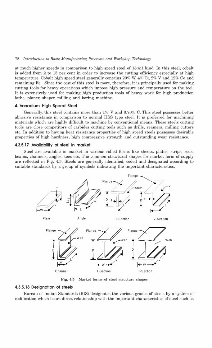
72 Introduction to Basic Manufacturing Processes and Workshop Technology
at much higher speeds in comparison to high speed steel of 18:4:1 kind. In this steel, cobaltis added from 2 to 15 per cent in order to increase the cutting efficiency especially at hightemperature. Cobalt high speed steel generally contains 20% W, 4% Cr, 2% V and 12% Co andremaining Fe. Since the cost of this steel is more, therefore, it is principally used for makingcutting tools for heavy operations which impose high pressure and temperature on the tool.It is extensively used for making high production tools of heavy work for high productionlathe, planer, shaper, milling and boring machine.
4. Vanadium High Speed SteelGenerally, this steel contains more than 1% V and 0.70% C. This steel possesses better
abrasive resistance in comparison to normal HSS type steel. It is preferred for machiningmaterials which are highly difficult to machine by conventional means. These steels cuttingtools are close competitors of carbides cutting tools such as drills, reamers, milling cuttersetc. In addition to having heat resistance properties of high speed steels possesses desirableproperties of high hardness, high compressive strength and outstanding wear resistance.
4.3.5.17 Availability of steel in marketSteel are available in market in various rolled forms like sheets, plates, strips, rods,
beams, channels, angles, tees etc. The common structural shapes for market form of supplyare reflected in Fig. 4.5. Steels are generally identified, coded and designated according tosuitable standards by a group of symbols indicating the important characteristics.
T
T TD
L L
D
V
T
W
L
T
Leg
L
L
AngleP late
Flange
Flange
Stem
T-S ection Z-S ection
Flange Flange Flange
W ebW eb W eb
D D D
L L L
WWW
Channe l T-S ection T-S ection
Fig. 4.5 Market forms of steel structure shapes
4.3.5.18 Designation of steelsBureau of Indian Standards (BIS) designates the various grades of steels by a system of
codification which bears direct relationship with the important characteristics of steel such as

Ferrous Materials 73
tensile strength, chemical composition. physical and surface conditions. According to thismethod a particular grade designation would be applicable to certain steel only. Hence steelmay be designated by a group of symbols indicating the important characteristics.
(i) 1025. Indicates C-25 which is plain carbon steel,
(ii) 1112. It is a free cutting steel having percentage
C = 0.13 Max.
Mn = 0.7 – 1.0 %
P = 0.07 – 0.12 %
S = 0.16 – 0.23%
(iii) 4145. It is Cr-Mo – steel having percentage
C = 0.33 – 0.38%
Mn = 0.7 – 0.9%
P or S = 3.025%
Si = 0.2 – 0.35%
Cr = 0.81 – 1.1 %
Mo = 0.18 – 0.25%
(iv) 8650. It is Ni-Cr-Mo alloy steel having percentages
Ni = 0.4 – 0.7%
Cr = 0.4 – 0.6%
Mo = 0.15 – 0.25%
(v) 3145. It is a Ni-Cr steel having
Ni = 0.3 – 0.35%
Cr = 0.4 – 0.5%
(vi) 2330. It is a Ni-steel having percentages
C = 0.28 – 0.33%
S = 0.04%
Mn = 0.5%
Si = 0.02 – 0.35 %
Ni = 3.25 – 3.75%
(vii) 5150 It is a Cr-Steel
Following symbol recommended to be used to indicate heat treatment given to steel andis to be suffixed at the end of normal symbol of steel.
(1) Annealed and softened a
(2) Case carburized c
(3) Hard, drawn, cold reduced d
(4) Hot rolled h
(5) Normalized n
(6) Spherodised 0

74 Introduction to Basic Manufacturing Processes and Workshop Technology
(7) Patented p
(8) Hardened and Tempered q
(9) Stress relieved s
(10) Tempered t
Steel QualityFollowing symbols should be recommended to be suffixed with the normal steel symbol
to indicate the steel quality
(1) Non-ageing quality A
(2) Stabilizing against stress corrosion and inter-annular attack E
(3) Control cooled ensure freedom from flakes L
(4) Fully-killed (deoxidized) D
(5) Semi-killed D2
(6) Rimming quality R
(7) Grain size controlled G
(8) Hardenability controlled H
(9) Inclusion controlled I
(10) Structural homogeneity guaranteed by macro- structure test M
Carbon Tool Steel (Annealed)Carbon tool steel in annealed condition is explained as below with designation and uses.
C-60 Spindles for machine tools, coupling, crank shaft axles and pinions.
C-65 Small washers and thin stamped parts.
C- 70 Buffer spring shock absorbers.
C- 75 Light flat, springs formed from annealed stock.
C-75-C-85 Flat and coils springs for automobiles and railway vehicles.
C-50 to C-113 Springs made from small flat section.
Plain Carbon Structural Steel
Designation and Uses
St-42 For bridge and building construction, railway rolling stock, screwspikes and oil well castings.
St-44 Pressure vessels, fasteners, value fittings for compressed gas cylindersand railway rolling stock.
St-47 For railway rolling stock, pressure parts of marine and land boilersand rivets for air receivers.
St-50 For mines, forgings of marine and engine parts.
St-52-54 For railway wheels, electric tramways cars.

Ferrous Materials 75
4.4 QUESTIONS1. How are engineering materials classified?
2. How ferrous metals differ from non-ferrous metals?
3. State the name of important iron ores.
4. How cast iron differs from steel?
5. Write short notes on :
(i) Pig iron
(ii) Grey cast iron
(iii) White cast iron
(iv) Ductile cast iron
(v) Malleable cast iron.
6. Discuss in brief the effect of impurities in cast iron.
7. What is wrought iron? Discuss in brief its chemical composition, properties and applications.
8. What are plain carbon steels? Discuss in brief the classification of plain carbon steels andalso state few applications of different plain carbon steels.
9. What are alloy steels? Discuss in brief the effects of alloying elements on steel.
10. How are alloy steels classified?
11. Write short notes on:
(i) Stainless steel
(ii) High speed steel
(iii) Designation of steels.
Non-Ferrous Materials 77
impurities are oxide, silica, clay and titanium oxide. It is found in India in the states of Biharand Madhya Pradesh.
ManufactureThe bauxite is purified and then dissolved in fused cryolite (double fluoride of aluminium
and sodium). The aluminium is then separated from this solution by electrolysis at about910°C.
PropertiesPure aluminium has silvery color and lusture. It is ductile, malleable and very good
conductor of heat and electricity. It has a very high resistance to corrosion than the ordinarysteel. Its specific gravity is 2.7 and melting point is 658°C. Its tensile strength varies from95 to 157 MN/m2. In proportion to its weight it is quite strong. In its pure state the metalwould be weak and soft for most purposes, but when mixed with small amounts of otheralloys, it becomes hard and rigid. It may be blanked, formed, drawn, turned, cast, forged anddie cast. Its good electrical conductivity is an important property and is broadly used foroverhead cables. It forms useful alloys with iron, copper, zinc and other metals.
ApplicationsIt is mainly used in aircraft and automobile parts where saving of weight is an advantage.
The high resistance to corrosion and its non-toxicity make it a useful metal for cookingutensils under ordinary conditions. Aluminium metal of high purity has got high reflectingpower in the form of sheets and is, therefore, widely used for reflectors, mirrors and telescopes.It is used in making furniture, doors and window components, rail road, trolley cars, automobilebodies and pistons, electrical cables, rivets, kitchen utensils and collapsible tubes for pastes.Aluminium foil is used as silver paper for food packing etc. In a finely divided flake form,aluminium is employed as a pigment in paint. It is a cheap and very important non ferrousmetal used for making cooking utensils.
5.2.1 Aluminium alloysThe aluminium may be easily alloyed with other elements like copper, magnesium, zinc,manganese, silicon and nickel to improve various properties. The addition of small quantitiesof alloying elements into other metals helps to converts the soft and weak metal into hardand strong metal, while still retaining its light weight. Various aluminium alloys are
1. Duralumin,
2. Y-alloy,
3. Magnalium and
4. Hindalium
These alloys are discussed as below:
5.2.2 DuraluminIt is an important wrought alloy. Its composition contains following chemical contents.
Copper = 3.5-4.5%Manganese = 0.4-0.7%Magnesium = 0.4-0.7%Aluminium = 94%

78 Introduction to Basic Manufacturing Processes and Workshop Technology
PropertiesDuralumin can be very easily forged, casted and worked because it possesses low melting
point. It has high tensile strength, comparable with mild steel combined with the characteristicslightness of Al. It however possesses low corrosion resistance and high electrical conductivity.This alloy possesses higher strength after heat treatment and age hardening. After working,if this alloy is age hardened for 3 or 4 days. This phenomenon is known as age hardening.It hardens spontaneously when exposed to room temperature. This alloy is soft enough fora workable period after it has been quenched. It is light in weight as compared to its strengthin comparison to other metals. It can be easily hot worked at a temperature of 500°C.However after forging and annealing, it can also be cold worked.
Applications Duralumin is used in the wrought conditions for forging, stamping, bars, sheets, tubes,
bolts, and rivets. Due to its higher strength and lighter weight, this alloy is widely used inautomobile and aircraft components. To improve the strength of duralumin sheet, a thin filmof Al is rolled along with this sheet. Such combined sheets are widely used in air-craftindustries. It is also employed in surgical and orthopedic work, non-magnetic work andmeasuring instrument parts constructing work.
5.2.3 Y -alloyY-Alloy is also called copper-aluminium alloy. The addition of copper to pure aluminiumincreases its strength and machinability. Its composition contains following chemical contents.
Copper = 3.5-4.5%
Manganese = 1.2-1.7%
Nickel = 1.8-2.3%
Silicon, magnesium, iron = 0.6% each
Aluminium = 92.5%.
PropertiesThe addition of copper in aluminium increases its strength and machinability. Y-alloy can
be easily cast and hot worked. Like duralumin, this alloy is heat treated and age hardened.The age-hardening process of Y-alloy is carried out at room temperature for about five days.
ApplicationsY-Alloy is mainly used for cast purposes, but it can also be used for forged components
like duralumin. Since Y -alloy has better strength than duralumin at high temperatures,therefore it is much used in aircraft engines for cylinder heads, pistons, cylinder heads, crankcases of internal combustion engines die casting, pump rods etc.
5.2.4. MagnaliumMagnalium is an alloy of aluminium, magnesium, copper, nickel and tin etc. It contains
Al = 85 to 95%, Cu = 0 to 25%, Mg = 1 to 5%,
Ni = 0 to 1.2%, Sn = 0 to 3%, Fe = 0 to 0.9%,
Mn = 0 to 0.03%, Si = 0.2 to 0.6%.
Non-Ferrous Materials 79
It is made by melting the aluminium with 2-10% magnesium in a vacuum and thencooling it in a vacuum or under a pressure of 100 to 200 atmospheres.
PropertiesMagnalium is light in weight and brittle. This alloy possesses poor castability and good
machinability. It can be easily welded.
ApplicationsDue to its light weight and good mechanical properties, it is mainly used for making
aircraft and automobile components.
5.2.5 HindaliumHindalium is a common trade name of aluminium alloy. It is an alloy of aluminium, magnesium,manganese, chromium and silicon etc. In India, it is produced by Hindustan AluminiumCorporation Ltd., Renukoot (U.P.). Hindalium is commonly produced as a rolled product in 16gauges. Utensils manufactured by this alloys are strong and hard, easily cleaned, low costthan stainless steels, having fine finish, having good scratch resistance, do not absorb muchheat etc.
ApplicationsHindalium is mainly used for manufacturing anodized utensil. Utensils manufactured by
this alloys are strong and hard, easily cleaned, low cost than stainless steels, having finefinish, having good scratch resistance, do not absorb much heat etc.
5.3 COPPER
Copper is one of the most widely used non-ferrous metals in industry. It is extracted from oresof copper such as copper glance, copper pyrites, melachite and azurite. Copper ores are foundin the state of Sikkim and Bihar of India and Bharma.
ManufactureCopper ore is first ground and then smelted in a reverberatory or small blast furnace for
producing an impure alloy. Then the air is blown through the molten metal to removesulphur and iron contamination to obtain blister copper in the converter. Copper is thenrefined further using electrolysis processes.
PropertiesPure copper is soft, malleable and ductile metal with a reddish-brown appearance. It is
a good conductor of electricity. It is non-corrosive under ordinary conditions and resistsweather very effectively. Its tensile strength varies from 300 to 470 MN/m2 and melting pointis 1084°C. It is one of the best conductors of heat and it is highly resistant to corrosion. Thisnon ferrous metal can withstand severe bending and forging without failure. It does not castwell. If copper is heated to red heat and cooled slowly it becomes brittle, but if cooled rapidlyit becomes soft, malleable and ductile. It can be welded at red heat.
ApplicationsCopper is mainly used in making electric cables and wires for electric machinery, motor
winding, electric conducting appliances, and electroplating etc. It can be easily forged, casted,rolled and drawn into wires. Copper in the form of tubes is used widely in heat transfer work

80 Introduction to Basic Manufacturing Processes and Workshop Technology
mechanical engineering field. It is used for household utensils. It is also used in productionof boilers, condensers, roofing etc. It is used for making useful alloys with tin, zinc, nickeland aluminium. It is used to form alloys like brass, bronze and gun metal. Alloys of copperare made by alloying it with zinc, tin, and lead and these find wide range of applications.Brass, which is an alloy of copper and zinc, finds applications in utensils, household fittings,decorative objects, etc. Bronze is an alloy of copper and tin and possesses very good corrosionresistance. It is used in making valves and bearings. Brass and bronze can be machined athigh speeds to fine surface finish.
The following copper alloys are important
1. Copper-zinc alloys (Brasses)
2. Copper-tin alloys (Bronzes)
5.3.1 BrassesBrasses are widely used alloy of copper (main constituent) and zinc. They also contain smallamounts of lead or tin or aluminium. The most commonly used copper-zinc alloy is brass.There are various types of brasses, depending upon the proportion of copper and zinc. Thefundamental a binary alloy comprises 50% copper and 50% zinc. By adding small quantitiesof other elements, properties of brass may be greatly changed. For example addition of lead(1 to 2%) improves the machining quality of brass. It has a greater-strength than that ofcopper, but has a lower thermal and electrical conductivity. Brasses alloys are very resistantto atmospheric corrosion and can be easily soldered. They can be easily fabricated by processeslike spinning and can also be electroplated with metals like nickel and chromium. Some ofcommon phases of brass are discussed as under.
Alpha PhaseIf the copper crystal structure is face centered cubic (FCC), there will be up to 36% of
zinc. This solid solution is known as alpha brass. It has good mechanical properties, goodcorrosion resistance but it possesses lower electrical conductivity than copper.
Beta PhaseIf the amount of zinc increases beyond 36%, beta brass will appear in the microstructure
of the slowly cooled brass. This has body centered cubic structure (BCC). This phase is hardbut quite tough at room temperature.
Gamma PhaseWhen zinc content is increased in brass beyond 45%, then gamma phase is appeared in
its structure. This structure is extremely brittle, rendering an alloy which makes it unsuitablefor general engineering purposes. The various types of brasses are discussed as under.
5.3.1.1 Red BrassRed brass is an important material used for heat conducting purposes. Itcontains
Cu = 85%
Zn = 15%.
PropertiesRed brass is having excellent corrosion resistance and workability. It possesses tensile
strength ranging from 27-31 kg/mm 2. Percentage elongation of this brass is 42-48.
Non-Ferrous Materials 81
ApplicationsRed brass is mainly utilized for making, heat exchanger tubes, condenser, radiator cores,
plumbing pipes, sockets, hardware, etc.
5.3.1.2 Yellow Brass or Muntz MetalYellow brass is also known as muntz metal. It contains
Cu = 60%
Zn = 40%
Muntz metal is having high strength and high hot workability. It is having tensilestrength 38 Kg/mm2 (approximately). The percentage elongation of this brass is 45%.
ApplicationsYellow brass or muntz metal is suitable for hot working by rolling, extrusion and stamping.
It is utilized for making small various components of machine and electrical equipment suchas bolts, rods, tubes, valves and fuses. This metal is utilized for making for pump parts, valves,taps, condenser tubes, sheet form for ship sheathing (because of excellent corrosion resistance).
5.3.1.3 Cartridge BrassIt contains 70% Cu and 30% Zn. It is having good combination of strength and ductility.
It is having tensile strength between 31-37 kg/mm2. Percentage elongation of this brass is55-66%. It is generally processed into rolled sheets. The metal alloy can be easily cold workedusing cold working processes such as wire drawing, deep drawing and pressing.
ApplicationsIt is utilized for making for making tubes, automotive radiator cores, hardware fasteners,
rivets, springs, plumber accessories and in tube manufacture.
5.3.1.4 Admiralty BrassIt contains
Cu = 71%
Zn = 29%
Sn = 1%
Properties1. Admiralty brass is highly resistant to corrosion.
2. It is highly resistant to impingement attack of sea water.
3. It is having tensile strength 30 kg/mm2 (approx.).
4. It can be cold worked
5. It possesses good corrosion resistance to sea water corrosion.
6. The percentage elongation of admiralty brass is 65%.
ApplicationsAdmiralty brass is utilized for making condenser tubes in marine and other installations.
It is used for making plates used for ship building. It is utilized also for making bolts, nuts,washers, condenser plant and ship fittings parts, etc.

82 Introduction to Basic Manufacturing Processes and Workshop Technology
5.3.1.5 Naval BrassNavel brass is commonly used for making marine components. It contains
Cu = 59%
Zn = 40%
Sn = 1%
PropertiesProperties of naval brass are similar to muntz metal. As 1% zinc is replaced by 1% tin
in Muntz metal to make navel brass, corrosion resistance of this material to sea water issignificantly improved. The percentage elongation of navel brass is 47% and its tensile strengthis 38 kg/mm2 (approx.).
ApplicationsNavel brass is commonly utilized for making marine hardware casting, piston rods,
propeller shafts, welding rods etc.
5.3.1.6 Manganese BrassManganese brass is sometimes also called manganese bronze. It contains
Cu = 60%
Zn = 38%
Mn = 0.5%
Fe = 1.0%
Sn = 0.5%
PropertiesManganese brass possesses sufficient toughness and good corrosion resistance. It is very
active in reducing the oxides of other metals.
ApplicationsManganese brass is utilized for making hydraulic rams, valves and cylinders, tubes,
pump rods, propellers, bolts, nuts etc.
5.3.1.7 Iron Brass or Delta MetalIron brass or delta brass contains
Cu = 60%
Zn = 37%
Fe = 3%
Iron brass or delta metal is hard, strong, tough, and having good corrosion resistance.It can be casted easily.
ApplicationsIf corrosion is to be resisted in mild steel, then some amount of iron brass or delta metal
is added in mild steel.

Non-Ferrous Materials 83
5.3.1.8 Gilding BrassGilding brass is a very cheap metal for making jewellery, decorative and ornamental
products. It generally containsCu = 85%Zn = 15%
ApplicationsBecause of better appearance this metal is commonly used for jewellery, decorative and
ornamental work.
5.3.1.9 Free Cutting BrassFree cutting brass contains
Cu = 57.5% Zn = 40%Pb = 2.5%
Free cutting brass is highly machinable and it does not allow bending.
ApplicationsFree cutting brass is used for making cast, forged or stamped blanks to be used for
further machining such as high speed turning and screwing.
5.3.1.10 Lead BrassLead brass is also known as cloak brass which contains
Cu = 65%
Zn = 34%
Pb = 1%
ApplicationsLead brass or cloak brass is used in making small gears and pinions for clock work.
5.3.2 BronzesBronze is a common alloy of copper and tin. The alloys of copper and tin are generally termedas bronzes. The wide range of composition of these alloys comprise of 75 to 95% copper and5 to 25% tin.
Properties of bronzes Bronze has higher strength, better corrosion resistance than brasses. It is comparatively
hard and resists surface wear and can be shaped or rolled into wire, rods and sheets veryeasily. It has antifriction or bearing properties. Bronze is costlier than brass. The tensilestrength of bronze increases gradually with the amount of tin, reaching a maximum when tinis about 20%. However the percentage of tin content if increases beyond this amount, thetensile strength decreases very rapidly. Bronze is most ductile when it contains about 5% oftin. As the amount of tin increases about 5%, the ductility gradually decreases and practicallydisappears with about 20% of tin. Whereas presence of zinc in the bronze increases fluidityof molten metal, strength and ductility.
Some of the common types of bronzes are discussed as under:

84 Introduction to Basic Manufacturing Processes and Workshop Technology
5.3.2.1 Phosphor BronzeWhen bronze contains phosphorus in very small amount, then phosphor bronze is produced.
A common type of phosphor bronze has the following composition.Cu = 89 to 94%Sn = 6 to 10%P = 0.1 to 0.3%
PropertiesTensile strength, ductility, elasticity, soundness of castings, good wearing quality and
resistance to fatigue of phosphor bronze increases with increase of phosphorus in bronze. Thismaterial possesses good corrosion resistance especially for sea water, so that it is much usedfor propeller blades. Phosphor bronze of proper composition can be easily casted, forged,drawn, and cold rolled.
ApplicationsPhosphorus bronze is used making for bolts, electric contact springs, bearings, bushes,
gears, ship sheathing, valve parts, propeller blades, worm wheels, gears, nuts for machinelead screws, pump parts, linings and for many other purposes. It is also suitable for makingsprings and corrosion resistance mine cables.
5.3.2.2 Silicon bronzeSilicon bronze contains
Cu = 96%Si = 3%
Mn or Zn = 1%Silicon bronze has good general corrosion resistance of copper combined with higher
strength. It can be cast, rolled, stamped, forged and pressed either hot or cold and it can bewelded by all the usual methods.
ApplicationsSilicon bronze is widely used for making boilers, tanks, stoves or where high strength and
good corrosion resistance is required. It is used also for making screws, tubing’s, pumps etc.
5.3.2.3 Beryllium bronzeBeryllium bronze is a copper base alloy contains
Cu = 97.5%Br = 2.5%
Beryllium bronze possesses higher tensile strength than other bronzes. It possessesexcellent corrosion resistance. It is having high yield point and high fatigue limit. It is havinggood hot and cold resistance. This can be heat treated by precipitation hardening. It possessesexcellent formability in soft condition, and high fatigue and creep resistance in hardenedcondition. However it involves high cost.
ApplicationsBeryllium bronze is particularly suitable material for making springs, tubes, diaphragms
and electrical contacts, heavy duty electrical switches, cams and bushings. This is used for
Non-Ferrous Materials 85
springs, heavy duty electrical switches, cams and bushings. Having non-sparking characteristics,it is used for making chisels and hammers using for such conditions where spark might causeexplosion. It has a film forming and a soft lubricating property, which makes it more suitableas a bearing metal. Since the wear resistance of beryllium copper is five times that ofphosphorous bronze, therefore it is used as a bearing metal in place of phosphor bronze.
5.3.2.4 Manganese bronzeManganese bronze is an alloy of copper, zinc and little percentage of manganese. The
usual composition of this bronze is
Copper = 60%
Zinc = 35%
Manganese = 5%
Manganese bronze is highly resistant to corrosion. It is stronger and harder than phosphorbronze.
ApplicationsManganese bronze is mainly used for bushes, plungers, feed pumps, rods etc. Worm
gears are frequently made from this bronze.
5.3.2.5 Aluminium BronzeAluminium bronze possesses
Cu = 85 to 88%
Al = 8 to 11%
Fe = 3%
Sn = 0.5%
PropertiesThe aluminium bronze with 8% aluminium possesses very good cold working properties.
When iron is added to this metal, its mechanical properties are greatly improved by refiningthe grain size and improving the ductility. The maximum tensile strength of this alloy is 450MPa with 11 % aluminium. This material possesses good resistance to corrosion and it issomewhat difficult to cast due to oxidation problem.
ApplicationsAluminium bronze is generally used for making fluid connection fittings, gears, propellers,
air pumps, bushings, tubes, slide and valves etc. Cams and rollers are commonly producedusing this alloy.
5.3.2.6 Bell MetalBell metal generally contains
Cu = 66.7%
Sn = 33.3%
Bell metal is very strong. It possesses resistance to corrosion water and atmosphere. Itis used to make bells.
86 Introduction to Basic Manufacturing Processes and Workshop Technology
5.3.3 ConstantanThe composition of constantan is
Cu = 55%
Ni = 45%
Properties(i) Constantan is high specific resistance
(ii) Specific resistance is unaffected by temperature variation.
ApplicationsConstantan is used for accurate resistors like thermo-couples,
(i) Wheet-stone bridge,
(ii) Low temperature heaters and
(iii) Resistances
5.4 NICKEL AND ITS ALLOY
Nickel and its alloys are discussed as under.
5.4.1 NickelNickel is a silvery shining white metal having extremely good response to polish. The mostimportant nickel’s ore is iron sulphides which contain about 3% of nickel. About 90% of thetotal production of nickel is obtained by this source. This ore is mainly found in Canada andNorway.
ManufactureThe ore of Nickel is initially roasted to reduce the sulphur content and then smelted to
separate the gangue from it. Matte (impure product of the smelting of sulphide ore especiallythose of nickel or copper, is known as matte) delivered by the smelting furnace is then putin a Bessemer converter to oxidize the iron. The iron oxide thus combines with a limestoneand quartz and form the slag. The Bessemer’s matte consists chiefly of copper and nickelsulphides.
PropertiesNickel is as hard as steel. It possesses good heat resistance. It is tough and having good
corrosion resistance. Its melting point is 1452°C and specific gravity is 0.85. At normaltemperature, nickel is paramagnetic. Nickel alloys are sometimes used for their high potentialfield strengths, some for their permeability and some for their high coercive force. When itcontains small amount of carbon, it is quite malleable. It is somewhat less ductile than softsteel, but small amount of magnesium improves ductility considerably.
ApplicationsNickel is used in kitchen utensils and appliances, and in laundry and dairy machinery.
It is extensively useful for electroplating plating work for protecting surfaces of iron and brassfrom corrosion. It is also utilized as an important alloying element in some type of cast ironand steel. It is helpful for making stainless steel. Its alloys are discussed as under.

Non-Ferrous Materials 87
5.4.2 Nickel AlloysThe important nickel alloys are haste alloy, Monel metal, inconel, nomonic and ni-chrome.
5.4.2.1 Haste Alloy or high Temprature AlloyHaste alloy or high temperature alloy is mainly a nickel base alloy. It contains
Ni = 45%,
Cr = 22%,
Mo = 9%,
Co = 1.5%,
W = 0.5%,
C = 0.15% and
Fe = Remaining
Properties(i) It can be hot and easily cold worked, casted and welded.
(ii) It has high resistance corrosion especially to acids and salts except nitric acid(HNO3).
(iii) It can be machined also.
(iv) This alloy is used where the resistance to corrosion is of consideration.
ApplicationsThe high temperature alloys are those alloys which can withstand high temperatures
about 1100°C. These alloys are used in components of nuclear plants, jet and rocketengines etc.
5.4.2.2 Monel MetalMonel metal is an important alloy of nickel and copper. It contains 68% Ni, 30% Cu, 1%
Fe and small amount of other constituents like iron, manganese, silicon and carbon.
PropertiesMonel metal is superior to brass or bronze in resisting corrosion and in retaining its
strength at high temperature. It is magnetic at ordinary temperatures. Its mechanical propertiesare improved by cold working. It can be cast, cold and hot worked, forged and welded. Itresembles nickel in appearance and is strong, ductile and tough. It has good mechanicalproperties and can retain them even at elevated temperatures. It has high excellent corrosionresistance.
ApplicationsMonel metal is also used for pump fittings, condenser tubes, sea water exposed parts etc.
It is widely used for making turbine blades, containers, parts for chemical plants, food handlingmachinery parts, marine parts, pump impellers, propellers, evaporators and heat exchangersin chemical works.

88 Introduction to Basic Manufacturing Processes and Workshop Technology
5.4.2.3 InconelInconel contains
Ni = 80%Cr = 14%Fe = 6%
PropertiesInconel has high resistance to corrosion and oxidation at elevated temperatures. It can be
readily cold-worked and hot-worked, but does not respond to heat treatment. It contains highmechanical properties coupled corrosion and heat resisting properties. It can be cast, forged,rolled and cold drawn. Its specific gravity is 8.55 and melting point is 1395°C. Its BrinellHardness is about 160BHN. It can be soft soldered or can be welded by oxyacetylene welding.
ApplicationsInconel is used for making springs, exhaust manifold of aircraft engines, machinery for
food processing industries, especially milk and milk products. It is widely used for processinguranium and for sheathing for high temperature heating elements.
5.4.2.4 Nomonic alloy The composition of nomonic alloy is given as under.
Cr = 15 to 18%Co = 15 to 18%Ti = l.2 to 4.0%Al = l.5%Ni = Remaining
Properties(i) Nomonic is a special type of nickel alloy having good strength
(ii) It can be easily heat treated to attain excellent properties for very high temperatureservice.
ApplicationsNomonic is widely used for making gas turbine engines
5.4.2.5 Ni-ChromeNi-chrome contains
Ni = 60%
Cr = 15%
Fe = 20%
PropertiesNi-chrome is non-corrosive. It can easily withstand high temperatures without oxidation.
ApplicationsNi-chrome is commonly used for making electrical resistance wire for electric furnaces
and heating elements.
Non-Ferrous Materials 89
5.5 LEADLead is a bluish grey metal with a high metallic lusture when freshly cut. It is a very durableand versatile material. The heavy metal obtained from the bottom of the furnace is furtheroxidized in Bessemer’s converter to remove most of the impurities.
PropertiesLead has properties of high density and easy workability. It has very good resistance to
corrosion and many acids have no chemical action on it. Its melting point is 327°C and specificgravity is 11.35. It is the softest and heaviest of all the common metals. It is very malleableand may be readily formed into foil. It can readily be scratched with fingernail when pure.
ApplicationsThe lead pipes installed by the Romans in the public baths in Bath, England, nearly 2000
years ago are still in use. Lead is used in safety plug in boilers, fire door releases and fuses.It is also used in various alloys such as brass and bronze. It finds extensive applications assheaths for electric cables, both overhead and underground. Its sheets are used for makingroofs, gutters etc. It is employed for chemical laboratory and plant drains. In the solderingprocess, an alloy of lead and tin is most widely utilized as a solder material for joining metalsin joining processes.
5.6 ZINCZinc is bluish grey in color and is obtained from common ores of zinc are zinc blende (ZnS),zincite (ZnO), calamine (ZnCO3). These ores are commonly available in Burma. The oxide isheated in an electric furnace where the zinc is liberated as vapor. The vapors are then cooledin condensers to get metallic zinc.
PropertiesZinc possesses specific gravity is 6.2 and low melting point of 480°C. Its tensile strength
is 19 to 25 MPa. It becomes brittle at 200°C and can be powdered at this temperature. Itpossesses high resistance to corrosion. It can be readily worked and rolled into thin sheetsor drawn into wires by heating it to 100-150°C.
ApplicationsWith regards to industrial applications, zinc is the fourth most utilized metal after iron,
aluminium, and copper. Zinc is commonly used as a protective coating on iron and steel inthe form of a galvanized or sprayed surface. It is used for generating electric cells and makingbrass and other alloys. The oxide of zinc is used as pigment in paints. Parts manufacturedby zinc alloys include carburetors, fuel pumps, automobile parts, and so on.
5.7 TINTin is recognized as brightly shining white metal. It does not corrode in wet and dry conditions.Therefore, it is commonly used as a protective coating material for iron and steel. The mainsource of tin is tinstone. Large deposits of tinstone occur in Tairy (Burma) and small quantitiesin Hazaribagh in Bihar of India
ManufactureTo obtain crude tin, the ores of tins are crushed, calcined, washed and then smelted in
a furnace using anthracite coal and sand. The crude tin is then refined in a reverberatory
90 Introduction to Basic Manufacturing Processes and Workshop Technology
furnace to get commercially pure tin. Chemically pure tin is made by electrolytic depositionfrom commercial tin.
PropertiesTin is considered as a soft and ductile material. It possesses very good malleability. Its
melting point is 232°C and specific gravity is 7.3. It is malleable and hence can be hammeredinto thin foils
ApplicationsTin-base white metals are commonly used to make bearings that are subjected to high
pressure and load. Tin is used as coating on other metals and alloys owing to its resistanceto corrosion. It is employed in low melting point alloys as a substitute for Bismuth. It isgenerally preferred as moisture proof packing material. Because of its high malleability, itfinds application in tin cans for storing food and food items.
5.7.1 Tin Base AlloyTin base alloy is also known as Babbitt metal which contains
Sn = 88%
Sb = 8%
Cu = 4%
PropertiesBabbit metal possesses excellent antifriction properties and sufficient mechanical strength.
It can be easily casted. It is expensive because of high tin content.
ApplicationsBecause of the above properties, Babbit metal is the most common bearing metal used
with cast iron boxes where the bearings are subjected to high pressure and load applications.
5.8. BEARING OR ANTIFRICTION ALLOYS
A bearing alloy or antifriction alloy commonly possesses good wearing quality, low co-efficientof friction, high thermal conductivity, good casting qualities, non-corrosive properties, abilityto withstand high pressure and impact, low shrinkage after coating and less cost. VariousBearing Metals are:
5.8.1 Admiralty Gun MetalThe composition of admiralty gun metal generally contains
Cu = 88%
Sn = 10%
Pb = 2%
PropertiesAdmiralty gun metal is having tensile strength of the order of 270 MN/m2. It possesses
elongation of about 20% and Brinell Hardness of 65 BHN.
Non-Ferrous Materials 91
ApplicationsAdmiralty gun metal is generally utilized where lubrication is needed and oiling is
difficult.
5.8.2 Lead BronzeLead bronze generally contains
Cu = 80%
Sn = 10%
Pb = 10%
PropertiesLead bronze possesses tensile strength of 230 MN/m2 , Brinell Hardness of 65 BHN and
elongation of about 15%.
ApplicationsLead bronze possesses has antifriction properties and hence is generally utilized where
lubrication is doubtful.
5.8.3 Hard Bearing BronzeHard bearing bronze basically contains
Cu = 85%
Sn = 15%
PropertiesHard bearing bronze generally possesses tensile strength of 220 MN/m2, 100 BHN and
percentage elongation of 2%.
ApplicationsHard bearing bronze is commonly used for high compressive loads such as locomotive
slide valves etc.
5.9 CUTTING TOOL MATERIAL
Few material for cutting tools are generally used which are as follows.
(i) High Speed Steel
These have superior hot hardness and it can retain the hardness up to 900°C. Init tungsten produces martensite structure with other elements. It is three types
18-4-1 High Speed Steel.
It has 18% tungsten, 4% chromium, 1% vanadium and 0.7% carbon: This is used formachining or metal cutting speed above 50 m/min. But for higher cutting speedvanadium is increased.
Molybdenum high Speed Steel
It has 6% Molybdenum, 4% chromium and 2% vanadium.

92 Introduction to Basic Manufacturing Processes and Workshop Technology
Cobalt High Speed SteelIt is also known as super high speed steel. It has 1-12% cobalt, 20% tungsten, 4%chromium and 2% vanadium. It is very good for high cutting speed.
(ii) Cemented CarbidesThe use of tungsten as an alloying elements gives steel the properly of retaininghardness at high temperature up to 900°C to 1000°C. Carbide is made by mixingtungsten metal powder with carbon and heating the mixture to the about 1600°C inthe atmosphere of hydrogen until the two substance have under gone the chemicalreaction to produce tungsten carbides. Cemented carbide is a powder metallurgicalproduct. The powder of several carbide compounds are pressed and bonded togetherin a matrix to from a cemented material. Today, the following three groups ofcemented carbides are extensively applied for cutting elements of tools.(a) WC + Co + (WC-TiC-TaC-NiC) for use in the machining of steels.(b) WC + Co for use in the machining of cast irons and non ferrous metals.(c) TiC + Ni + Mo for use in the machining of high temperature high strength metals.Cemented carbides have a very high hardness (second only to diamond) and high wearresistance to abrasion. They do not loose their cutting properties i.e., hardness overa wide range of temperature up to 900-1000°C. Therefore tools tipped with cementedcarbides are capable of efficiently machining the hardest metals, including hardenedsteels at high cutting speeds. Such tools can operate at cutting speeds from 16 to 25folds those permitted for tools made of carbon tool steels. One drawback of cementedcarbides is their brittleness. Very high stiffness (Young’s modulus is about three timesthat of steel) of the cemented carbides requires that they are well supported on ashank of sufficient thickness, for even a small amount of bonding deformation in amaterial of this stiffness may induce very high tensile stresses. Cemented carbidesare weak in tension than in compression. They have a strong tendency to formpressure welds at low cutting speeds. In view of this they should be operated at speedsconsiderably in excess of those used with high speed steel tools. This caused formachine tools of increased power. Carbides that obtain high cobalt percentage aretougher and stronger than that contain low cobalt. Hence they are used for roughcutting, interrupted cuts and for milling. The low cobalt variety is used for finishedoperations such as turning with a smooth chip cross-section and a continuous cut. Itis recommended to keep the braze metal as thin as possible.
(iii) Ceramics ToolThe latest development in the metal cutting tools uses Aluminium oxide, generallyreferred as ceramics. These tools are made by compacting Al2O3 powder in a mouldat about 280 kg/cm2 or more. The part is then sintered at 2200°C. This method isalso known cold pressing ceramic tool. Hot pressed ceramic tool materials areexpensive owing to their higher mould costs. These are made in form of tips thatare clamped to metal shanks. These tools have very low heat conductivity andpossess extremely high compressive strength. However they are quite brittle. Thehave low bending strength. They can with stand temperatures up to 1200°C and canbe used at cutting speeds 10 times that of high speed cutting tools and 4 times thatof cemented carbides. They are chiefly used for single point cutting tools for semi-finish and turning of cast iron, plastics and other work. Heat conductivity of ceramicsis very low and hence these tools are generally used without a coolant.
Non-Ferrous Materials 93
(iv) Carbides tool
It may be produced from carbides of tungsten, titanium and tantanum with samepercentage, of cobalt. The product is obtained by a special technique known aspowder metallurgy. Usually it contains 82% tungsten, 8% cobalt and l0% titaniumand the product is obtained by a special technique known as power metallurgy.Cobalt acts as a binder and others are very hard substance. This tool contains highdegree of hardness and resistance. It is able to retain hardness at elevatedtemperatures up to l000°C. It can be operated at speeds 5 to 6 times or (more)higher than those with high speed steel.
(v) Diamond
It is a noble material which is so costly that its application becomes limited. It isa hardest material. It can be used for cutting at a speed 50 times greater thanH.S.S. tools. It can retain its hardness even at a temperature of 1650. It has lowcoefficient of friction and high heat conductivity. Diamond tools are used to producegood surface finish.
5.10 COMPOSTION AND APPLICATIONS OF FEW TYPICAL MATERIALS
The composition and applications of few typical materials is given in Table 5.1.
Table 5.1 Composition and Applications of Few Typical Materials
S. No Alloy Composition Uses
1 Duralmin, 95% Aluminium + 4% Copper+ Light structures, extruded0.5% Manganese + 0.5% Magnesium sections and sheet
2 Gun metal 90% copper + 10% zinc Small valves, fittings forwater services
3 Monel 67% Ni + 28% Copper + remaining Valve parts for superheatedcarbon, iron and Manganese steam turbine blades
4 Phosphor bronze 90% Copper + 9.7% Tin + 0.3% Bearings, worm wheels,Phosphorus rods sheets
5 High carbon steel 0.8% to 1.5% Carbon + Files, dies for wire drawing,remaining iron clutch disc
6 Spheroidal CI 3.2%-4.5% carbon 1-4% Si 0.1-8% Mn For high wear resistance0.1% P 0-3.5% Ni 0.05-0.1% Mn
7 Wrought iron 99% Pig Iron + 0.12% Carbon + Chains, crane hooks,0.25% Phosphorus + 0.05 % Sulphur railway couplings
5.11 CERAMICS MATERIALS
Ceramic materials are non-metallic solids made of inorganic compounds such as oxides,nitrides, borides and carbides. Theses materials are fabricated by first shaping the powderwith or without the application of pressure into a compact form and after that it is subjectedto high temperature. Ceramics possesses electrical, magnetic, chemical and thermal propertieswhich are exceptionally good.
Examples: MgO, CdS, SiC, Al2O3, glass, cement, garnets, ferrites, concrete etc.

94 Introduction to Basic Manufacturing Processes and Workshop Technology
ApplicationsCeramic materials are utilized for making electronic control devices, computers, structures,
components of nuclear engineering and aerospace field.
5.12 COMPOSITES
Composites are mixture of materials such as metal and alloys and ceramics, metals andorganic polymers, ceramics and organic polymers.
Examples: Vinyl coated steels, steel reinforced concrete, fiber reinforced plastics, carbonreinforced rubber etc.
ApplicationsThese materials are used for making sports items, structures, and electrical devices.
5.13 SEMICONDUCTORS
Semiconductors are solid materials, either non-metallic elements or compounds which allowelectrons to pass through them. These materials occupy intermediate position betweenconductors and insulators. Semiconductors usually have high resistivity, negative temperaturecoefficient of resistance and are generally hard and brittle.
Examples: Germanium (Ge), Arsenic (As), Silicon (Si), Boron (B), Sulphur (S), Selenium(Se).
ApplicationsSemiconductors are utilized in making devices used in areas of telecommunication and
radio communication, electronics and power engineering, photocells, rectifiers etc.
5.14 ORGANIC POLYMERS
Polymers consist of carbon chemically combined with usually with hydrogen, oxygen or othernon- metallic substances. They are formed by polymerization reaction in which simple moleculesare chemically combined into long chain molecules.
Examples: Nylon, Teflon, Polyethylene, PVC, Terylene, Cotton etc.
ApplicationsPolymers are used in making packings, pipes, covers and insulating materials etc.
5.15 PLASTICS
Plastics are commonly known as synthetic resins or polymers. In Greek terminology, theterm polymer comprises ‘poly’ means ‘many’ and ‘mers’ means ‘parts’. Thus, the term, polymerrepresents a substance built up of several repeating units, each unit being known as amonomer. Thousands of such units or monomers join together in a polymerization reactionto form a ‘polymer’. Some natural polymers like starch, resins, shellac, cellulose, proteins,etc are vary common in today’s use. Synthetic polymers possess a number of large applicationsin engineering work. Therefore plastic materials are fairly hard and rigid and can be readilymolded into different shapes by heating or pressure or both. Various useful articles can beproduced from them rapidly, accurately and with very good surface quality. They can be easily

Non-Ferrous Materials 95
produced in different colors or as transparent. They are recognized by their extreme lightness,good corrosion resistance and high dielectric strength. Plastics are synthetic resins characterizedas a group by plastic deformation under stress. These materials generally are organic highpolymers (i.e. consisting of large chain like molecules containing carbon) which are formedin a plastic state either during or after their transition from a low molecular weight chemicalto a high molecular weight solid material. These materials are very attractive organicengineering materials and find extensive applications in industrial and commercial work suchas electrical appliances, automotive parts, communication products bodies (Telephone, Radio,TV), and those making household goods. They possess a combination of properties whichmake them preferable to other materials existing in universe.
Properties of plasticsThe properties of plastics are given as under.
1. Plastics are light in weight and at the same time they possess good toughnessstrength and rigidity.
2. They are less brittle than glass, yet they can be made equally transparent andsmooth.
3. Their high dielectric strength makes them suitable for electric insulation.
4. They resist corrosion and the action of chemicals.
5. The ease with which they can be mass-produced contributes greatly to their popularityas wrappers and bags.
6. They possess the property of low moisture absorption.
7. They can be easily molded to desired shapes.
8. They can easily be made colored.
9. They are bad conductance of heat.
10. They are hard, rigid and heat resistance.
11. They possesses good deformability, good resiatance against weather conditions, goodcolorability, good damping characteristics and good resistance to peeling.
Plastics are broadly classified into thermo plastics and thermo-setting plastics.
5.15.1 Thermo PlasticsThose plastics which can be easily softened again and again by heating are called thermoplastic.They can be reprocessed safely. They retain their plasticity at high temperature, i.e. theypreserve an ability to be repeatedly formed by heat and pressure. Therefore, they can beheated and reshaped by pressing many times. On cooling they become hard. They are sometimes also called as cold-setting plastics. They can be very easily shaped into tubes, sheets,films, and many other shapes as per the need.
Types of Thermo Plastics(A) Amorphous
1 Polystyrene
2 Acrylonitrite-butadiene-styrene
3 Mrthacrylate

96 Introduction to Basic Manufacturing Processes and Workshop Technology
4 P.V.C (Polyvinyl chloride)
5 Polychloroacetal
6 Auorinated polymers,
7 Polycarbonate etc.
(B) Crystalline
1 Polyethylene
2 Polyamides
3 Polyacetal
4 Polypropylene
The reason for the re-softening of thermoplastic resins with heat is that they are composedof linear or long chain molecules. Application of heat weakens the intermolecular bonds byincreasing thermal agitation of the molecules, and the material softens and thus plastic canbe easily molded and remolded without damage
5.15.2 Thermo-Setting PlasticsThose plastics which are hardened by heat, effecting a non-reversible chemical change, arecalled thermo-setting. Alternatively these plastics materials acquire a permanent shape whenheated and pressed and thus cannot be easily softened by reheating. They are commonlyknown as heat-setting or thermosets.
Thermosetting resins
(i) Phenol-formaldehyde resins
(ii) Urea-formaldehyde resins
(iii) Melamine-formaldehyde resins
(iv) Polyester resins
(v) Epoxy resins
(vi) Silicone resins
Other thermosetting compounds are phenol furfural, polysters, alkyds, and polyurethanes.The most common thermosetting compound is phenol formaldehyde which is discussed asunder.
Phenol formaldehydePhenol formaldehyde is called as bakelite due to the name of its inventor Bakelite. It is
the most commonly and widely used plastic. It is made by the reaction of phenol withformaldehyde. It has high strength, hardness, stability, rigidity and can be easily casted orlaminated. It is highly resistant to heat, electricity and water. It is made in dark color shades.Its general uses are in making articles such as stereo cabinets, radio cabinets, plugs, knobs,dials, bottle cap, pulleys, wheels, telephones, switches and handles.
Thermosetting resins, when subjected (once only) to the heat and pressure required forforming, change into a hard and rigid substance. Once done so, they cannot be softened againby the application of heat. The reason for the above phenomenon is that the thermosettingplastics consist of linear, relatively low molecular weight thermoplastic polymer chains withcross-links which bond the chains together with primary valence bonds. Such three-dimensional

Non-Ferrous Materials 97
polymers, once cross-linked, will not soften when heated (but may decompose disintegrate athigher temperatures) because this process is an irreversible chemical reaction and the entirestructure becomes essentially a single molecule. In contrast the thermoplastic resins can bere-softened and remolded by application of heat and pressure. They retain their plasticity athigh temperature, i.e. they preserve an ability to be repeatedly formed by heat and pressure.
5.15.3 Comparison Between Thermo Plastic and Thermosetting PlasticThermoplastic are those which are obtained from the substituted derivatives of ethylenewhich can be made to polymerize under the influence of heat and catalyst. These materialsare softened by heat and affected by certain solvent. A notable feature of these resins is theability of their scrap or rejects to be reworked along with the new material. Cellulose nitrate(celluloid) and polythene are the example of these materials. Where as thermosetting arethose which are formed into shape under heat and pressure and results in a permanentlyhard product. The heat first softens the material, but as additional heat and pressure isapplied, it becomes hard phenol formaldehyde (bakelite). Phenol furfural (Durite) is the exampleof thermosetting plastics. The comparison between thermo plastic and thermosetting plasticis given in Table 5.2.
Table 5.2 Comparison between Thermo Plastic and Thermosetting Plastic
S.No Thermo Plastic Thermosetting Plastic
1 They can be repeatedly softened by heat Once hardened and set, they do not soften withand hardened by cooling. the application of heat.
2 They are comparatively softer and less They are more stronger and harder thanstrong. thermoplastic resins
3 Objects made by thermoplastic resins Objects made by thermosetting resins can becan not be used at comparatively higher used at comparatively higher temperaturetemperature as they will tend to soften without damageunder heat.
4 They are usually supplied as granular They are usually supplied in monomeric ormaterial partially polymerized material form in which
they are either liquids or partially thermoplasticsolids.
5 Applications. Toys, combs, toilet goods, Applications. Telephone receivers, electric plugs,photographic films, insulating tapes, radio and T.V. cabinets, camera bodies,hoses, electric insulation, etc. automobile parts, tapes, hoses, circuit breaker
switch panels, etc.
5.15.4 Fabricating of Plastics(a) Themo-plastics can be formed by
(i) Injection molding.
(ii) Extrusion.
(iii) Blow molding.
(iv) Calendaring
(v) Thermo-forming.
(vi) Casting.
98 Introduction to Basic Manufacturing Processes and Workshop Technology
(b) Thermosetting plastics can be formed by(i) Compression or transfer molding.
(ii) Casting
Thermoplastics can be joined with the help of(i) Solvent cements.
(ii) Adhesive bonding(iii) Welding(iv) Mechanical fasteners
Thermosetting plastics can be joined with the help of(i) Adhesive bonding
(ii) Mechanical fasteners.
5.15.5 Additions in PolymerTo make polymer more for further processing of products, plastics, and some other materialare added to the polymers before or during polymerization. These materials are
CatalystsThey are also known accelerator or hardener. They act as catalysts to accelerate the
chemical reactions during polymerization of plastics.
FillersFillers are added to synthetic resins for increasing strength, stiffness and thermal
resistance of the plastics. These are clay, talc, alumina, carbon black, calcium carbonate, woodflour, mica, quartz, asbestos, glass fibres etc.
ModifiersModifiers are added to plastics for improving mechanical properties
PlasticizersPlasticizers are fluids of high molecular weight. They are added for softening the resins
at forming temperature and to improve their toughness at the finished stage and to impartflexibility to their finished products.
StabilizersThe additions of stabilizers to plastics help in preventing deterioration due to the action
of heat and light.
InitiatorsInitiators help in starting the reaction i.e. polymerization.
Dyes and pigmentsDyes and pigments are the coloring agents, added to impart different colors and shades
to plastic materials.
5.16 MATERIALS FOR NUCLEAR ENGINEERING PURPOSESThe various metals for producing nuclear energy are used as main materials namely
moderators, reflectors, fuel elements, fuel canning materials, control elements, and pressure

Non-Ferrous Materials 99
vessel materials. Uranium, thorium, plutonium, zirconium, beryllium, niobium and theiralloys are primarily used for nuclear engineering applications.
5.16.1 UraniumMost important metal found in nature and used for nuclear energy is uranium. It is used asa nuclear fuel and is radioactive, easily oxidized mat and exists in three allotropic forms. Ithas a poor resistance to corrosion and needs to be protected for use as fuel elements by rollcladding a thin aluminium or zirconium jacket. Therefore it is strengthened by a thin filmof aluminium or zirconium through a rolling process known as cladding. This metal in thepure condition is weak and is susceptible to severe irradiation damage and growth in thereactor environments. Addition of some alloying elements such as chromium, molybdenum,plutonium and zirconium are added to make great use of this material for generating nuclearpower. Uranium compounds have been found to give better service. Uranium oxide is rehighly refractory, shows no phase change in an inert atmosphere, possesses a good strengthand a high corrosion resistance. But it has a low thermal shock resistance, poor thermalconductivity and a high coefficient of in expansion. The melting point of uranium is 1850°C.
5.16.2 ThoriumThorium is another possible fuel and is also a radioactive metal like uranium. It is a nuclearfuel and is free from phase changes below 1480°C. It can be converted into uranium by betadecay. It can be converted into uranium by beta decay. In its pure form it is weak and soft,but its mechanical properties are improved by adding small amount of other elements e.g.,only 0.2% of carbon addition raises its tensile strength from. Its mechanical properties changedrastically by small addition of impurities. Small additions of titanium, zirconium, and niobiumdecrease the strength and hardness of the metal. Uranium addition increases the strengthof thorium. Thorium like uranium is an emitter of alpha rays and releases considerablequantity of the radioactive products during processing, but this being a cubic metal is lesssusceptible to irradiation damage. The melting point of thorium is 1845°C.
5.16.3 PlutoniumPlutonium is not a natural element but synthetic. It is produced through the absorption ofneutrons by uranium 238 and subsequent beta decays. It is a concentrated type of fuel usedin a fast reactor without a moderator. It is identified as highly toxic and chemically veryreactive material. It has a poor resistance to corrosion. This material can be easily oxidized.It is frequently used for production of atomic weapons and it possesses tremendous applicationsin breeder reactors.
5.16.4 ZirconiumThe natural form of zirconium contains 0.5 to 2% halfnium which is a strong absorber ofneutrons and must therefore be removed. It possesses excellent corrosion resistance againstmost of the acids and having good strength, good weldability and fatigue resistance. It has a poorresistance to CO2 at elevated temperatures and that can be further improved by adding 0.5%Cu and 0.5% Mo. It is specifically used in gas cooled reactors and cladding of fuel elements.
5.16.5. BerylliumBeryllium is specially used as a moderator, reflector and neutron source in nuclear reactors.It is a coarse grained light and brittle metal which possesses highly developed texture. During
100 Introduction to Basic Manufacturing Processes and Workshop Technology
melting, vacuum or inert gas is necessary because it is very reactive and forms compoundswith the furnace atmosphere and refractory materials. In order to fabricate components fromberyllium, powder metallurgy techniques are used.
5.16.6. NiobiumNiobium possesses good corrosion resistance, strength and ductility. It has a high meltingpoint of 2470°C. Its oxidation resistance above 400°C is indifferent, but can be greatly improvedby alloying elements. It is added to many base metals to produce heat resisting alloys but thismaterial is quite expensive.
5.17 MATERIAL SELECTION PROCEDURE FOR COMPONENTS
For selection a material for a particular application, one has to take into considerationvarious physical and mechanical properties of the material. Selection of material for amanufacturing process is an important decision. In many instances, the selection of a specificmaterial can even dictate the manufacturing process to be used. The selection of material alsohas an influence on the final cost of the product. It is important to note that the materialcost accounts to approximately 50% of the manufacturing cost. Hence, selection of manufacturingprocess for a material must be made with the due care. The stepwise approach for materialselection is as follows:
1 Initially material requirement is identified by keeping in view overall objectives ofthe part for which the selection of material is made. These objectives can bereferred with reference to cost, durability, life, etc.
2 The material requirements are identified through a number of materials. For example,low specific weight requirement is met by aluminium and also by nylon. Make a listof all such materials that meet all or most of the, requirements.
3 In case when more than one material appears to be suitable, the final choice shouldbe determined by considering influencing factors and restrictions like availability ofraw material, cost, inhibitions of aesthetics, and so on. For example, when we wantto select a material for manufacturing coins, the requirements are: the materialshould possess good ductility, hardness, corrosion resistance, high plasticity, andshould be light in weight. The list of materials that satisfy these requirements islarge including gold, silver, copper, and their alloys. Final selection may be madetaking into consideration cost and availability. As another example, one uses stainlesssteel for manufacturing shaving razor blades because the material selected shouldhave good malleability (ability to be hammered into thin sheets), corrosion resistance,more abrasive resistance, and economical. The edge may be alloyed to make it hardand retain sharpness.
The material selection procedure for the following products is given as under.
Rock crusher jawThe function of crusher jaws is to crush. The crusher jaws should be hard, shock
absorbing and require good compressive strength. For such properties we choose cast-ironbecause it has good castability, fluidity and good damping capacity. Its castings are made bydry sand casting process.

Non-Ferrous Materials 101
Binocular BodyIt is made by plastic materials containing cellulose acetate (Thermo plastics), polystyrene
(thermoplastics) phenol formaldehyde (thermo setting plastics) because these materials havehigh mechanical strength, impact resistance, transparency, colorability, fabricating quality,versatility, molding ability, high dielectric strength and high refractive index.
Diesel Engine PistonAs the function of piston to reciprocate in the cylinder, it will require good wear and
corrosion resistance and ability to with stand at high temperature. Therefore material likecast iron, bronze and aluminium alloy etc are preferred because of the requirements oflightness with sufficient strength, refractoriness stress relieving, hardening, and tempering,
Lifting hook of craneThe purpose hook in crane is to lift load and it will require bearing sudden and excessive
heavy shock-loads without permanent injury. For such purposes wrought iron will provebetter and it is not heat-treated.
Bed of high precision latheBed of high precision lathe needs high compressive strength, better shock absorbing
capacity, good damping capacity, corrosion resistance and good wear resistance, hardness andreduced effect of residual stresses for better functional requirements. Grey cast iron becauseits good lubricating properties due to presence of graphite will be suitable to meet thefunctional requirements. However for increasing its usefulness alloying elements such as Ni,Cr and Mo etc can also be alloyed in grey cast iron.
5.18 QUESTIONS1. How do you classify non-ferrous metals?
2. Discuss the properties and uses of the following non-ferrous metals:
(i) Copper (ii) Zinc (iii) Aluminium (iv) Magnesium
(v) Lead (vi) Tin (vii) Nickel. (viii) Plutonium
3. What is brass? Describe the composition, properties and uses of important types of brasses?
4. What is bronze? Describe the composition, properties and uses of different types of bronzes?
5. Explain the various types of aluminium alloys giving their composition, properties and uses?
6. Discuss the various types of nickel alloys?
7. Which are the main metals used in nuclear energy? Describe them in brief.
8. How will you select the suitable engineering materials for a particular application?
102 Introduction to Basic Manufacturing Processes and Workshop Technology
102
MELTING FURNACES
6.1 INTRODUCTION
Before pouring into the mold, the metal to be casted has to be in the molten or liquid state.Furnace is used for carrying out not only the basic ore refining process but mainly utilizedto melt the metal also. A blast furnace performs basic melting (of iron ore) operation to getpig iron, cupola furnace is used for getting cast iron and an electric arc furnace is used forre-melting steel. Different furnaces are employed for melting and re-melting ferrous and non-ferrous materials. The following are the factors which are responsible for the selection offurnace.
(i) Considerations of initial cost and cost of its operation.(ii) Relative average cost of repair and maintenance.
(iii) Availability and relative cost of various fuels in the particular locality.(iv) Melting efficiency, in particular speed of melting.(v) Composition and melting temperature of the metal.
(vi) Degree of quality control required in respect of metal purification of refining,(vii) Cleanliness and noise level in operation.
(viii) Personnel choice or sales influence.
Heat in a melting furnace is created by combustion of fuel, electric arc, electric resistance,etc. A furnace contains a high temperature zone or region surrounded by a refractory wallstructure which withstands high temperatures and being insulating minimizes heat losses tothe surroundings. For refining and melting the ferrous and non ferrous materials, variousfurnaces are used.
6.2 FURNACES FOR MELTING DIFFERENT MATERIALS
1. Grey Cast Iron(a) Cupola
(b) Air furnace (or Reverberatory Furnace)
(c) Rotary furnace
(d) Electric arc furnace
6CHAPTER
Melting Furnaces 103
2. Steel(a) Electric furnaces
(b) Open hearth furnace
3. Non-ferrous Metals(a) Reverberatory furnaces (fuel fired) (Al, Cu)
(i) Stationary
(ii) Tilting
(b) Rotary furnaces
(i) Fuel fired
(ii) Electrically heated
(c) Induction furnaces (Cu, Al)
(i) Low frequency
(ii) High frequency.
(d) Electric Arc furnaces (Cu)
(e) Crucible furnaces (AI, Cu)
(i) Pit type
(ii) Tilting type
(iii) Non-tilting or bale-out type
(iv) Electric resistance type (Cu)
(f) Pot furnaces (fuel fired) (Mg and AI)
(i) Stationary
(ii) Tilting
Some of the commonly used furnaces in foundries are discussed as under.
6.3 BLAST FURNACE
After mining, various kinds of iron ores are brought to the blast furnace which is the startingprocess for refining iron ores or mined ores and for the poduction of pig iron. Blast furnacewas invented in 14th century. A typical blast furnace along with its various parts is shownin Fig. 6.1. It is large steel shell about 9 mt. in diameter which is lined with heat resistantbricks. It is set on the top of brick foundation. There are four major parts of blast furnacefrom bottom to top hearth, bosh, stack and top. The hearth acts as a storage region formolten metal and molten slag. The charge of blast furnace possesses successive layers of ironore, scrap, coke, and limestone and some steel scrap which is fed from the top of the furnace.Iron ore exists as an aggregate of iron-bearing minerals. These mineral aggregates are oxidesof iron called hematite, limonite, and magnetite. They all contribute to the smelting process.Hematite is a red ore and contains about 70% iron. Limonite is a hydrated oxide and containsabout 60% iron. Magnetite is a magnetic oxide and contains about 72% iron. It takes about1.6 tons of iron ore, 0.65 ton of coke, 0.2 ton of lime-stone and about 0.05 ton of scrap ironand steel to produce 1 ton of pig iron. For burning this charge, about 4 tons of air is required.The impurities or other minerals are present in the ore. These impurities may be silicon,
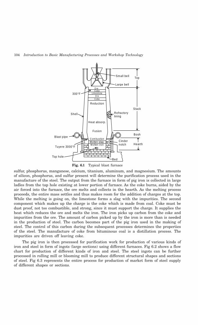
104 Introduction to Basic Manufacturing Processes and Workshop Technology
Sm all be ll
Large be ll
300°F
O reC o ke
L im e s to neO re
C o ke
Refracto rylining
Stack
Top
Bosh
HearthC indernotch
BedTop hole
Tuyere 3000°F
Blast p ipe
Shell
Reduction
Heat absorp .
Fusion
C om bus tionM o lten slagM o lten iron
Fig. 6.1 Typical blast furnace
sulfur, phosphorus, manganese, calcium, titanium, aluminum, and magnesium. The amountsof silicon, phosphorus, and sulfur present will determine the purification process used in themanufacture of the steel. The output from the furnace in form of pig iron is collected in largeladles from the tap hole existing at lower portion of furnace. As the coke burns, aided by theair forced into the furnace, the ore melts and collects in the hearth. As the melting processproceeds, the entire mass settles and thus makes room for the addition of charges at the top.While the melting is going on, the limestone forms a slag with the impurities. The secondcomponent which makes up the charge is the coke which is made from coal. Coke must bedust proof, not too combustible, and strong, since it must support the charge. It supplies theheat which reduces the ore and melts the iron. The iron picks up carbon from the coke andimpurities from the ore. The amount of carbon picked up by the iron is more than is neededin the production of steel. The carbon becomes part of the pig iron used in the making ofsteel. The control of this carbon during the subsequent processes determines the propertiesof the steel. The manufacture of coke from bituminous coal is a distillation process. Theimpurities are driven off leaving coke.
The pig iron is then processed for purification work for production of various kinds ofiron and steel in form of ingots (large sections) using different furnaces. Fig 6.2 shows a flowchart for production of different kinds of iron and steel. The steel ingots can be furtherprocessed in rolling mill or blooming mill to produce different structural shapes and sectionsof steel. Fig 6.3 represents the entire process for production of market form of steel supplyof different shapes or sections.
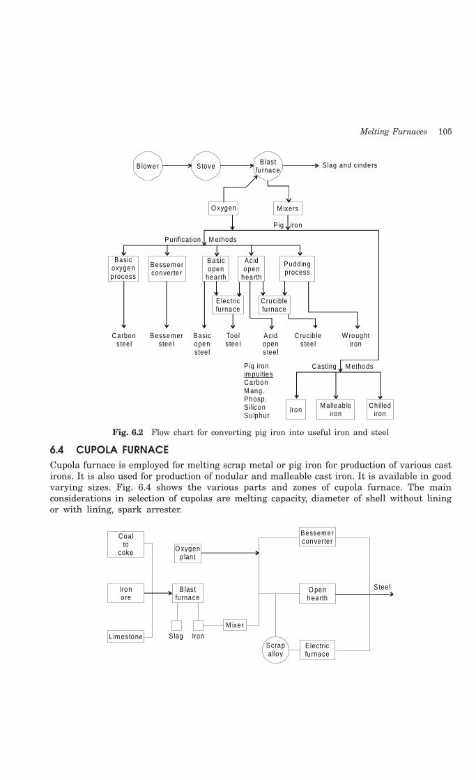
Melting Furnaces 105
Blower Stove Blastfu rnace
Slag and c inders
O xygen M ixers
P ig iron
Purification M ethods
Basicoxygenprocess
Bessemerconverte r
Basicopen
hearth
Acidopen
hearth
Pudd ingprocess
Electricfu rnace
Cruciblefu rnace
Acid openstee l
C ruciblestee l
W roughtiron
Carbonstee l
Bessemerstee l
Basicopenstee l
Too lstee l
P ig iron
CarbonM ang.Phosp.S iliconSu lphur
im puitiesCasting M ethods
Iron M alleab leiron
Ch illediron
Fig. 6.2 Flow chart for converting pig iron into useful iron and steel
6.4 CUPOLA FURNACECupola furnace is employed for melting scrap metal or pig iron for production of various castirons. It is also used for production of nodular and malleable cast iron. It is available in goodvarying sizes. Fig. 6.4 shows the various parts and zones of cupola furnace. The mainconsiderations in selection of cupolas are melting capacity, diameter of shell without liningor with lining, spark arrester.
Coalto
coke
Ironore
O xygenp lan t
B lastfu rnace
L im estone Slag Iron
M ixer
Bessemerconverte r
O penhearth
Stee l
E lectricfu rnace
Scrapa lloy
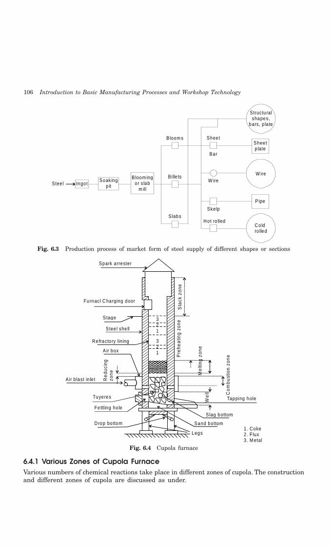
106 Introduction to Basic Manufacturing Processes and Workshop Technology
Structu ralshapes,
bars, p la te
Sheetp late
W ire
Pipe
Co ldro lled
Ingo tStee lSoaking
p it
B loom ingor s lab
m ill
B loom s
Bille ts
S labsHot ro lled
Skelp
W ire
Bar
Sheet
Fig. 6.3 Production process of market form of steel supply of different shapes or sections
Legs
Slag bottom
Sand bottom1. Coke2. Flux3 . M etal
Tapping holeWe
ll Com
bust
ion
zone
Mel
ting
zone
Pre
heat
ing
zone
Sta
ck z
one
Spark a rrester
Furnacl C harging door
Stage
Stee l she ll
Re fracto ry lining
Red
ucin
gzo
ne
A ir b last in le t
Tuyeres
Fettling ho le
Drop bo ttom
321
321Air box
Fig. 6.4 Cupola furnace
6.4.1 Various Zones of Cupola FurnaceVarious numbers of chemical reactions take place in different zones of cupola. The constructionand different zones of cupola are discussed as under.
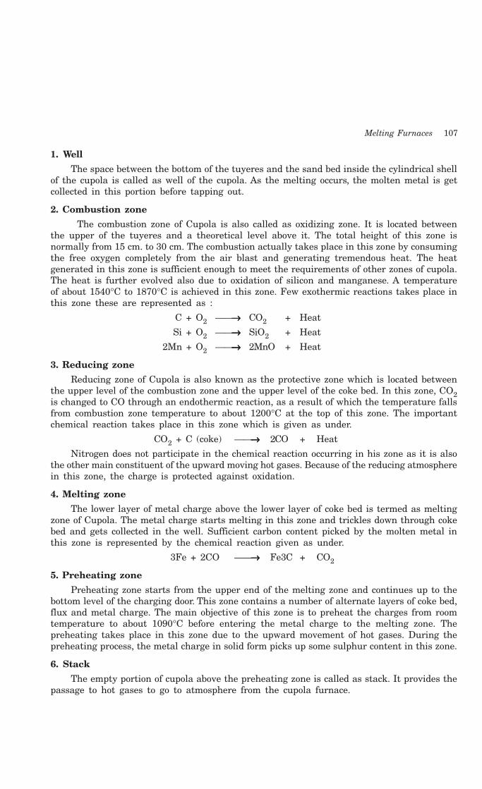
Melting Furnaces 107
1. Well
The space between the bottom of the tuyeres and the sand bed inside the cylindrical shellof the cupola is called as well of the cupola. As the melting occurs, the molten metal is getcollected in this portion before tapping out.
2. Combustion zone
The combustion zone of Cupola is also called as oxidizing zone. It is located betweenthe upper of the tuyeres and a theoretical level above it. The total height of this zone isnormally from 15 cm. to 30 cm. The combustion actually takes place in this zone by consumingthe free oxygen completely from the air blast and generating tremendous heat. The heatgenerated in this zone is sufficient enough to meet the requirements of other zones of cupola.The heat is further evolved also due to oxidation of silicon and manganese. A temperatureof about 1540°C to 1870°C is achieved in this zone. Few exothermic reactions takes place inthis zone these are represented as :
C + O2 ——→→→→→ CO2 + Heat
Si + O2 ——→→→→→ SiO2 + Heat
2Mn + O2 ——→→→→→ 2MnO + Heat
3. Reducing zone
Reducing zone of Cupola is also known as the protective zone which is located betweenthe upper level of the combustion zone and the upper level of the coke bed. In this zone, CO2is changed to CO through an endothermic reaction, as a result of which the temperature fallsfrom combustion zone temperature to about 1200°C at the top of this zone. The importantchemical reaction takes place in this zone which is given as under.
CO2 + C (coke) ——→→→→→ 2CO + Heat
Nitrogen does not participate in the chemical reaction occurring in his zone as it is alsothe other main constituent of the upward moving hot gases. Because of the reducing atmospherein this zone, the charge is protected against oxidation.
4. Melting zone
The lower layer of metal charge above the lower layer of coke bed is termed as meltingzone of Cupola. The metal charge starts melting in this zone and trickles down through cokebed and gets collected in the well. Sufficient carbon content picked by the molten metal inthis zone is represented by the chemical reaction given as under.
3Fe + 2CO ——→→→→→ Fe3C + CO2
5. Preheating zone
Preheating zone starts from the upper end of the melting zone and continues up to thebottom level of the charging door. This zone contains a number of alternate layers of coke bed,flux and metal charge. The main objective of this zone is to preheat the charges from roomtemperature to about 1090°C before entering the metal charge to the melting zone. Thepreheating takes place in this zone due to the upward movement of hot gases. During thepreheating process, the metal charge in solid form picks up some sulphur content in this zone.
6. Stack
The empty portion of cupola above the preheating zone is called as stack. It provides thepassage to hot gases to go to atmosphere from the cupola furnace.
108 Introduction to Basic Manufacturing Processes and Workshop Technology
6.4.2 Charging of Cupola FurnaceBefore the blower is started, the furnace is uniformly pre-heated and the metal and cokecharges, lying in alternate layers, are sufficiently heated up. The cover plates are positionedsuitably and the blower is started. The molten metal starts trickling down and collecting inthe well. The height of coke charge in the cupola in each layer varies generally from 10 to15 cms. The requirement of flux to the metal charge depends upon the quality of the chargedmetal and scarp, the composition of the coke and the amount of ash content present in thecoke. Generally about 40 kg to 50 kg of limestone, in form of flux, per metric ton of the metalis used. The amount of this flux to be charged should be properly determined. The excessamount of flux affects the acid lining of cupola. Lesser amount of the flux than required willresult in the loss of molten metal. First charge received of the molten metal is either allowedto drain out or used for rough castings. For having desired composition of the casting, it isessential to control the proportions of its various constituents at the stage of raw materialrequirement for melting. It is also necessary due to number of losses and gains of differentconstituents take place inside the cupola during the process of melting. These losses andgains in composition are identified for compensating purposes. The losses or gains of differentconstituents during melting as identified are given as under:
1. Iron – Loss of about 4%2. Carbon – Gain of about 0.1 to 0.15%.3. Silicon – Loss of about 10%4. Manganese – Loss of about 15 to 20%.5. Phosphorus – Practically no change.6. Sulphur – Gain of about 0.03 to 0.05%.
6.4.3 Working of Cupola FurnaceInitially the furnace prop is opened to drop the existing earlier charge residue. The furnaceis then repaired using rich refractory lining. After setting the prop in position, the fire isignited using firewood and then small amount of coke is used to pick fire. The little oxygenis then supplied for combustion. Lime, coke, and metal in balanced proportions are chargedthrough the charging door upon the coke bed and at proper time on starting the blower. Airis forced from wind box through tuyers into furnace. The forced air rise upward rough thestack furnaces for combustion of coke. Besides being fuel, the coke supports the charge untilmelting occurs. On increase of temperature, the lime stone melts and forms a flux whichprotects the metal against from excessive oxidation. Lime also fuses and agglomerates thecoke ash. The melting occurs and proceeds and molten metal is collected at the bottom.Molten metal may be tapped at intervals before each skimming, or the tap-hole may be leftopen with metal flowing constantly. In most cupolas slag is drained from the slag hole at theback of furnace. When metal is melted completely the bottom bar is pulled sharply under theplates and bottom is dropped. All remaining slag, un-burned coke or molten metal drops fromthe furnace. When the melt charge has cooled on closing furnace, it is patched and madeready for the next heat.
Applications of Cupola
Cupola is most widely used for melting practices for production of grey cast iron, nodularcast iron, malleable cast iron and alloy cast iron. It can be used for melting some copper-basealloys, and in duplexing and triplexing operations for making of steel, malleable cast iron andductile cast iron. Steel can be also prepared in cupola by employing duplexing and triplexing

Melting Furnaces 109
operations. In duplexing melting operation two furnaces are used, and triplexing operations,three furnaces are employed
6.4.4 Jamming of Cupola FurnaceJamming of cupola furnace is a very common problem for which sufficient care should betaken to prevent it. It occurs frequently due to the negligence of the furnace operator. Thecupola furnace may be either jammed temporarily or permanently and the same are discussedas under.
6.4.5 Temporary Jamming of Cupola FurnaceTemporary jamming of cupola furnace means the temporary suspension of air supply in
the tuyere zone due to choking of the tuyere mouths. This is caused mainly due to the lowtemperatures at the tuyere openings resulting in the solidification of iron and slag aroundthese openings. The air passage is hence chocked and the supply of air is temporarily stopped.It results in incomplete combustion of the coke/fuel inside the furnace and hence leads torapid reduction of the temperature in the furnace. Therefore this temporary jamming mustbe prevented by frequent poking of this solidified material by means of a poking bar throughthe tuyeres. The operator of cupola should always keep himself alert enough for not allowingsuch solidification for continue melting in furnace for a longer period.
6.4.6 Permanent Jamming of Cupola FurnacePermanent jamming of cupola furnace means a complete cut-off of the air supply to the cupoladue to the permanent choking of the air passage. This occurs on account of the overflow ofthe slag into the wind chamber. As the metal melts and starts collecting in the well of thefurnace, its level rises gradually and the slag being lighter, always floats on the top surfaceof the molten metal. If, the molten metal is not tapped out in time due to the negligence ofthe operator, the level of molten metal in furnace will start rising in the well and a stage willcome when this level approaches to the tuyere level. Any slightest delay further, in tappingby the cupola operator will cause the slag to flow through the tuyere openings into the windbelt. Since the slag comes in contact with the air at low temperature it quickly solidifies inthe wind belt as well as in the tuyers and therefore chock the passages of air flow permanentlyin the furnace. Hence the cupola furnace reaches in such undesirable condition on accountof the above occurrence. Therefore, to avoid such undesired situation, the operator of cupolafurnace should always be vigilant enough to tap the molten metal out from well of the cupolafurnace before the level of molten metal rises up to the tuyere level. Hence the cupolafurnace may continue melting for longer period.
6.4.7 Thermal Efficiency of Cupola FurnaceThermal efficiency of cupola furnace is the ratio of heat actually utilized in melting andsuperheating the metal to the heat evolved in it through various means. The total heatevolved involves the heat due burning of coke, heat evolved due to oxidation of iron, Si andMn and heat supplied by the air blast. During melting it is observed that approximately 48-70 % of the evolved heat is going as waste.
6.4.8 Precautions for Safety of Cupola FurnaceFor operating the cupola successfully, the following safety precautions must always be keptinto account.

110 Introduction to Basic Manufacturing Processes and Workshop Technology
1. For safety of Cupola, better quality refractory lining must be used for preparing orrepairing furnace so that it can withstand high temperature as produced inside thefurnace during melting, otherwise it will fuse and mix with molten metal to formslag.
2. The furnace operator during firing the furnace should always make an effort toplace the metal charge in the centre. He must ensure that the coke charge is welldistributed all around and towards the firebrick lining to ensure uniform and thoroughmelting of the metal.
3. As the air passes through the tuyeres, the temperature near the tuyere openingswill therefore be comparatively lower and consequently the molten iron and slagwill have a tendency to solidify near these openings and block them. This shouldbe prevented by frequent poking and removal of these materials by means of apoking rod through the tuyeres.
4 Amount of air supply should be properly controlled. An excess amount of air willalways result in waste of fuel and lowering of temperature inside and a lesseramount, than required, will cause incomplete combustion of fuel which is undesirable.
5. Tap hole must be properly closed by means of a well suitable plugging means. Claymixed with an equal amount of coal dust forms a very suitable mixture for pluggingup the tap hole.
6 In closing the tap-hole, precaution must be taken to press the plug downwards inthe hole so that the splash of the molten metal, during plugging does not fall onthe hands of the furnace operator.
7 Molten metal should always be tapped out well in time before its level rises too highin the well of the cupola furnace. Any delay of tapping molten metal, the slagfloating on the surface of the molten metal, will start flowing into the wind beltthrough the tuyeres and air passage will be choked and it will result in severeproblem of the jamming of cupola furnace.
6.5 OPEN HEARTH FURNACE
In open hearth furnace, pig iron, steel scrap etc. are melted to obtain steel. This furnace iswidely used in American foundries for steel production. The hearth is surrounded by roof andwalls of refractory bricks as shown in Fig. 6.5. The charge is fed through a charging door andis heated to 1650°C mainly by radiation of heat from the burning of gaseous fuels above it. Thisheat is obtained by the burning of sufficiently pre-heated air and gas. Such pre-heated air of gasis obtained by passing them though arc shaped hot regenerators at a lower level. This containsfire bricks which are arranged to extract heat from exhaust gases. In the furnace air and fuelare passed through a honeycomb of hot firebrick, called checkers. It preheats the air and fuelso that they are ready for combustion when they enter the hearth. The products of combustionat the same time pass through the checkers at the other end of the furnace. The hot gases heatthe checkers. The process then reverses itself, and the newly heated checkers now are used toheat the air and the fuel. It is said as a regenerative process. The products of combustion aftergiving up their heat to the checkers pass up through the stack. On firing of coke, the chargeis heated. Part of the heat necessary, results from radiation from the low hot roof of thechamber. The furnace is raised bricked in with the charging platform, at the rear, also raisedso that the charge may be put into the furnace. The melt is tapped off the front into large ladles.

Melting Furnaces 111
The chemical composition of the end product depends upon the lining, the charge, and thecontrol impurities added during the melt after the melt has been tapped off into the ladle. Thelining plays a major roll in the control of impurities. For magnesite lined furnace, the chargeconsists of pig iron, limestone, and scrap iron. The limestone forms a slag. This slag and theoxygen in the air combine to remove impurities. The slag reacts with the sulfur and the
1 2 34
1
Air
G as
Hea
rth
66
1 . Wa lls of refracto ry bricks, 2 . Roof, 3. M elting cham ber,4 . A ir and gas ducts, 5 . Charging doors, 6 . Checkerwork
5
Fig. 6.5 Open hearth furnace
phosphorus in the metal, while the bubbling air causes oxidation of the carbon and silicon. Iftoo much carbon is present in the melt, iron ore is added. The oxygen from the iron oxide burnsout the excess carbon. If the carbon content is too low, pig iron is added. This replenishes thecarbon. Other alloying elements like Cr, Ni. Co, W, Mo, V etc. are added as needed.Ferromanganese may be added to the crucible after tapping. For acid lining furnace, the chargeshould be scrap iron and low-phosphorus pig iron. Limestone is required to keep the slag fluid.As described above, the basic lining burns phosphorus, silicon, and carbon. The slag is tappedoff by the molten metals being allowed to overflow the sides of the crucible into a slag pot.Oxygen is one of the most important elements used in the reduction of the molten metal. Rust,scale, slag, and limestone are some of the sources of oxygen. Oxygen is introduced into thefurnace with oxygen lances through the roof of the furnace. Twice the oxygen input will doublethe carbon reduction. This increases the steel production of the furnace.
6.6 PIT FURNACE
Pit furnace is a type of a furnace bath which is installed in the form of a pit and is used formelting small quantities of ferrous and non ferrous metals for production of castings. It isprovided with refractory inside and chimney at the top. Generally coke is used as fuel. It isprovided with refractory lining inside and chimney at the top. Natural and artificial draughtcan be used for increasing the capability towards smooth operation of the furnace. Fig. 6.6shows the typical pit furnace.
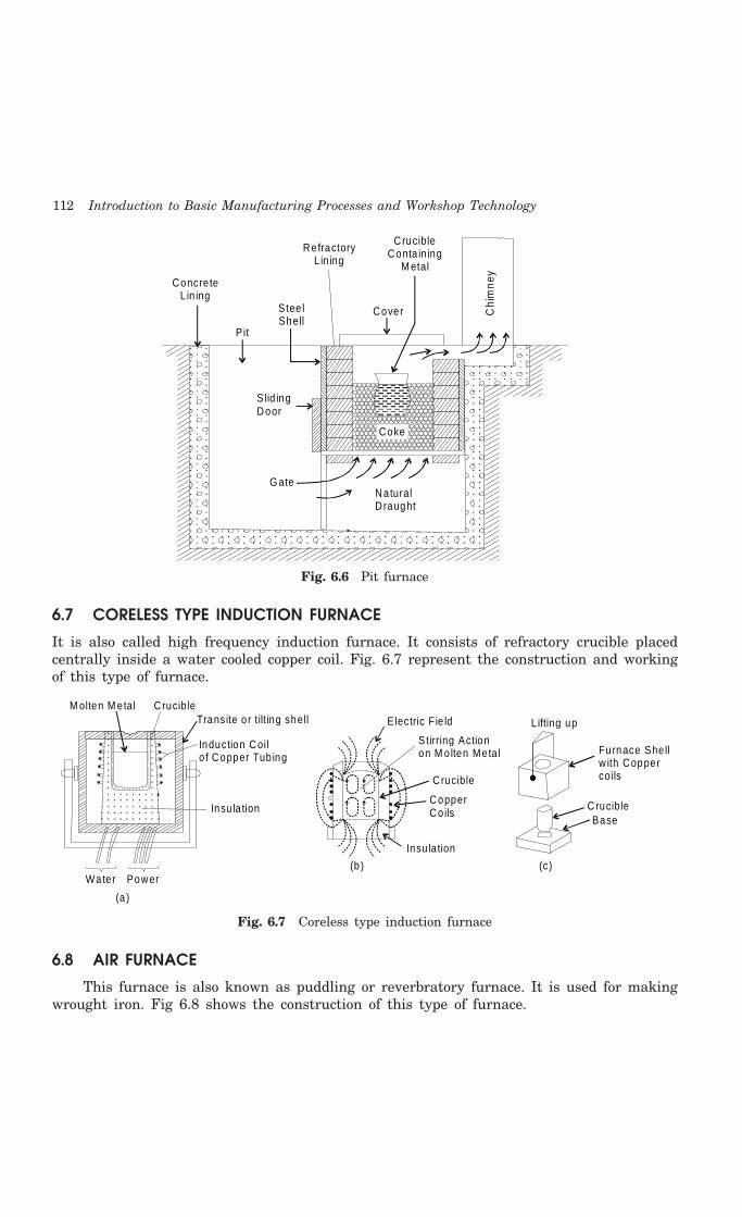
112 Introduction to Basic Manufacturing Processes and Workshop Technology
Chi
mne
y
Cover
CrucibleConta in ing
M etal
RefractoryL in ing
Stee lShell
Concre teL in ing
Pit
S lid ingDoor
NaturalD raught
G ate
Coke
Fig. 6.6 Pit furnace
6.7 CORELESS TYPE INDUCTION FURNACE
It is also called high frequency induction furnace. It consists of refractory crucible placedcentrally inside a water cooled copper coil. Fig. 6.7 represent the construction and workingof this type of furnace.
M olten M etal C rucibleTransite o r tilt ing shell
Induction Coilo f Copper Tub ing
Insu la tion
Water Power
(a )
L ifting up
Furnace She llw ith Coppercoils
C rucibleBase
(c)
E lectric Fie ld
Stirring Actionon M o lten Meta l
C rucible
CopperCo ils
Insu la tion
(b )
Fig. 6.7 Coreless type induction furnace
6.8 AIR FURNACE
This furnace is also known as puddling or reverbratory furnace. It is used for makingwrought iron. Fig 6.8 shows the construction of this type of furnace.

Melting Furnaces 113
Sigh t Ho le
Bungs
Fire Bridge Skim m ingDoor
Ch im ney
FiringDoor
FireP lace
FireBars
TAP Hole M olten Iron Hearth
Fig. 6.8 Air furnace
6.9 METHODS OF MEASURING TEMPERATURE
Furnace temperature is measured by following methods namely (i) Electrical pyrometers (2)Thermo electric pyrometers (3) Radiation pyrometers (4) Optical pyrometers and (5) Photo-electric cells.
An important radiation pyrometer is discussed as under.
Crucible Teapot P ouring
(a ) (b ) (c)
Bottom Pouring(f)(e )(d )
M old
M old
Laddle
Fig. 6.9 Pouring practices
6.9.1 Radiation PyrometerRadiation pyrometer is a temperature device by which the temperature of hot body is measuredby measuring the intensity of total heat and light radiation emitted by a hot body. A radiationpyrometer works on the principle of focusing the energy from all wave lengths of radiationupon a sensitive element thus causing a force to be developed in the element which may be
114 Introduction to Basic Manufacturing Processes and Workshop Technology
a resistance pyrometer or a thermo couple. All the radiations are concentrated by concavemirror upon the hot junction of a thermo couple. Mirror placed in inclined position is usedto indicate whether correct focus can be obtained.
6.10 POURING PRACTICES
Molten metal is collected in ladles from furnaces and skimmed properly before pouring intothe mould. Some of the pouring practices are shown in Fig 6.9.
6.10 QUESTIONS1 What are the general principles of the melting practice?
2 What important factors are considered during melting?
3 What are the factors which govern the selection of a suitable type of furnace for melting aparticular metal?
4 What characteristics a refractory material should possess to make it suitable for use infurnaces? How many types of refractory are there?
5 Sketch a blast furnace. Describe its construction and working.
6 Make a neat sketch of a cupola, indicating its various zones and describe the following:
(i) Construction
(ii) Preparation before operations
(iii) Charging method
(iv) Different zones and their functions
(v) Operation
(vi) Advantages
(vii) Limitations and
(viii) Application.
7 What do you mean by basic and acid cupolas? Where each type is preferred and why?
8 How is air requirement for cupola calculated
9 Why is the flux used during melting of metals in cupola?
10 How do you determine the thermal efficiency of a cupola furnace?
11 How will you specify a cupola furnace?
12 What necessary precautions are required in operating the cupola?
13 What are the expected gains in or losses of the various constituents of metal charge duringmelting and how are these constituents controlled?
14 Why does a cupola sometimes get jammed up? How can it be prevented?
15 Explain with the help of neat sketches the construction and working of the following typesof crucible furnaces: (a) A coal fired pit furnace, (b) An oil fired tilting furnace, and (c) A gasfired crucible furnace
16 What are crucible furnaces? Where are they preferred and why?
17 What are the different types of electric furnaces? Describe anyone of them.
18 Describe crucible furnaces.
19 Write short notes on the following:
(a) Open-hearth furnace and (b) Resistance furnace.

Melting Furnaces 115
20 What is refining?
21 What are the different types of pouring ladles?
22 Describe the construction working and uses of core less type induction furnace.
23 What do you understand by fluxing?
24 Name the different types of fluxes, arid describe anyone of them.
25 Describe the purpose for using the pyrometers in melting practice.
116 Introduction to Basic Manufacturing Processes and Workshop Technology
116
PROPERTIES AND TESTING OF METALS
7.1 PROPERTIES OF METALS
The important properties of an engineering material determine the utility of the materialwhich influences quantitatively or qualitatively the response of a given material to imposedstimuli and constraints. The various engineering material properties are given as under.
1. Physical properties
2. Chemical properties
3. Thermal properties
4. Electrical properties
5. Magnetic properties
6. Optical properties, and
7. Mechanical properties
These properties of the material are discussed as under.
7.1.1 Physical PropertiesThe important physical properties of the metals are density, color, size and shape (dimensions),specific gravity, porosity, luster etc. Some of them are defined as under.
1. Density
Mass per unit volume is called as density. In metric system its unit is kg/mm3. Because ofvery low density, aluminium and magnesium are preferred in aeronautic and transportationapplications.
2. Color
It deals the quality of light reflected from the surface of metal.
3. Size and shape
Dimensions of any metal reflect the size and shape of the material. Length, width,height, depth, curvature diameter etc. determines the size. Shape specifies the rectangular,square, circular or any other section.
7CHAPTER
Porperties and Testing of Metals 117
4. Specific Gravity
Specific gravity of any metal is the ratio of the mass of a given volume of the metal tothe mass of the same volume of water at a specified temperature.
5. Porosity
A material is called as porous or permeable if it has pores within it.
7.1.2 Chemical PropertiesThe study of chemical properties of materials is necessary because most of the engineeringmaterials, when they come in contact with other substances with which they can react, sufferfrom chemical deterioration of the surface of the metal. Some of the chemical properties ofthe metals are corrosion resistance, chemical composition and acidity or alkalinity. Corrosionis the gradual deterioration of material by chemical reaction with its environment.
7.1.3 Thermal PropertiesThe study of thermal properties is essential in order to know the response of metal tothermal changes i.e. lowering or raising of temperature. Different thermal properties arethermal conductivity, thermal expansion, specific heat, melting point, thermal diffusivity.Some important properties are defined as under.
Melting Point
Melting point is the temperature at which a pure metal or compound changes its shapefrom solid to liquid. It is called as the temperature at which the liquid and solid are inequilibrium. It can also be said as the transition point between solid and liquid phases.Melting temperature depends on the nature of inter-atomic and intermolecular bonds. Thereforehigher melting point is exhibited by those materials possessing stronger bonds. Covalent,ionic, metallic and molecular types of solids have decreasing order of bonding strength andmelting point. Melting point of mild steel is 1500°C, of copper is 1080°C and of Aluminium is650°C.
7.1.4 Electrical PropertiesThe various electrical properties of materials are conductivity, temperature coefficient ofresistance, dielectric strength, resistivity, and thermoelectricity. These properties are definedas under.
1. Conductivity
Conductivity is defined as the ability of the material to pass electric current through iteasily i.e. the material which is conductive will provide an easy path for the flow of electricitythrough it.
2. Temperature Coefficient of Resistance
It is generally termed as to specify the variation of resistivity with temperature.
3. Dielectric Strength
It means insulating capacity of material at high voltage. A material having high dielectricstrength can withstand for longer time for high voltage across it before it conducts thecurrent through it.
118 Introduction to Basic Manufacturing Processes and Workshop Technology
4. Resistivity
It is the property of a material by which it resists the flow of electricity through it.
5. Thermoelectricity
If two dissimilar metals are joined and then this junction is heated, a small voltage (inthe milli-volt range) is produced, and this is known as thermoelectric effect. It is the base ofthe thermocouple. Thermo -couples are prepared using the properties of metals.
7.1.5 Magnetic PropertiesMagnetic properties of materials arise from the spin of the electrons and the orbital motionof electrons around the atomic nuclei. In certain atoms, the opposite spins neutralize oneanother, but when there is an excess of electrons spinning in one direction, magnetic fieldis produced. Many materials except ferromagnetic material which can form permanent magnet,exhibit magnetic affects only when subjected to an external electro-magnetic field. Magneticproperties of materials specify many aspects of the structure and behavior of the matter.Various magnetic properties of the materials are magnetic hysteresis, coercive force andabsolute permeability which are defined as under.
1. Magnetic Hysteresis
Hysteresis is defined as the lagging of magnetization or induction flux density behind themagnetizing force or it is that quality of a magnetic substance due to energy is dissipated init on reversal of its magnetism. Below Curie temperature, magnetic hysteresis is the risingtemperature at which the given material ceases to be ferromagnetic, or the falling temperatureat which it becomes magnetic. Almost all magnetic materials exhibit the phenomenon calledhysteresis.
2. Coercive Force
It is defined as the magnetizing force which is essential to neutralize completely themagnetism in an electromagnet after the value of magnetizing force becomes zero.
3. Absolute Permeability
It is defined as the ratio of the flux density in a material to the magnetizing forceproducing that flux density. Paramagnetic materials possess permeability greater than onewhereas di-magnetic materials have permeability less than one.
7.1.6 Optical PropertiesThe main optical properties of engineering materials are refractive index, absorptivity,absorption co-efficient, reflectivity and transmissivity. Refractive index is an important opticalproperty of metal which is defined as under.
Refractive Index
It is defined as the ratio of velocity of light in vacuum to the velocity of a material. Itcan also be termed as the ratio of sine of angle of incidence to the sine of refraction.
7.1.7 Mechanical PropertiesUnder the action of various kinds of forces, the behavior of the material is studied that
measures the strength and lasting characteristic of a material in service. The mechanicalproperties of materials are of great industrial importance in the design of tools, machines and

Porperties and Testing of Metals 119
structures. Theses properties are structure sensitive in the sense that they depend upon thecrystal structure and its bonding forces, and especially upon the nature and behavior of theimperfections which- exist within the crystal itself or at the grain boundaries. The mechanicalproperties of the metals are those which are associated with the ability of the material to resistmechanical forces and load. The main mechanical properties of the metal are strength, stiffness,elasticity, plasticity, ductility, malleability, toughness, brittleness, hardness, formability, castabilityand weldability. These properties can be well understood with help of tensile test and stressstrain diagram. The few important and useful mechanical properties are explained below.
1. Elasticity
It is defined as the property of a material to regain its original shape after deformationwhen the external forces are removed. It can also be referred as the power of material tocome back to its original position after deformation when the stress or load is removed. Itis also called as the tensile property of the material.
2. Proportional limit
It is defined as the maximum stress under which a material will maintain a perfectlyuniform rate of strain to stress. Though its value is difficult to measure, yet it can be usedas the important applications for building precision instruments, springs, etc.
3. Elastic limit
Many metals can be put under stress slightly above the proportional limit withouttaking a permanent set. The greatest stress that a material can endure without taking upsome permanent set is called elastic limit. Beyond this limit, the metal does not regain itsoriginal form and permanent set will occurs.
4. Yield point
At a specific stress, ductile metals particularly ceases, offering resistance to tensileforces. This means, the metals flow and a relatively large permanent set takes place withouta noticeable increase in load. This point is called yield point. Certain metals such as mild steelexhibit a definite yield point, in which case the yield stress is simply the stress at this point.
5. Strength
Strength is defined as the ability of a material to resist the externally applied forces withbreakdown or yielding. The internal resistance offered by a material to an externally appliedforce is called stress. The capacity of bearing load by metal and to withstand destructionunder the action of external loads is known as strength. The stronger the material thegreater the load it can withstand. This property of material therefore determines the abilityto withstand stress without failure. Strength varies according to the type of loading. It isalways possible to assess tensile, compressive, shearing and torsional strengths. The maximumstress that any material can withstand before destruction is called its ultimate strength. Thetenacity of the material is its ultimate strength in tension.
6. Stiffness
It is defined as the ability of a material to resist deformation under stress. The resistanceof a material to elastic deformation or deflection is called stiffness or rigidity. A material thatsuffers slight or very less deformation under load has a high degree of stiffness or rigidity.For instance suspended beams of steel and aluminium may both be strong enough to carrythe required load but the aluminium beam will “sag” or deflect further. That means, the steel

120 Introduction to Basic Manufacturing Processes and Workshop Technology
beam is stiffer or more rigid than aluminium beam. If the material behaves elastically withlinear stress-strain relationship under Hooks law, its stiffness is measured by the Young’smodulus of elasticity (E). The higher is the value of the Young’s modulus, the stiffer is thematerial. In tensile and compressive stress, it is called modulus of stiffness or “modulus ofelasticity”; in shear, the modulus of rigidity, and this is usually 40% of the value of Young’smodulus for commonly used materials; in volumetric distortion, the bulk modulus.
7. Plasticity
Plasticity is defined the mechanical property of a material which retains the deformationproduced under load permanently. This property of the material is required in forging, instamping images on coins and in ornamental work. It is the ability or tendency of materialto undergo some degree of permanent deformation without its rupture or its failure. Plasticdeformation takes place only after the elastic range of material has been exceeded. Suchproperty of material is important in forming, shaping, extruding and many other hot or coldworking processes. Materials such as clay, lead, etc. are plastic at room temperature and steelis plastic at forging temperature. This property generally increases with increase in temperatureof materials.
8. Ductility
Ductility is termed as the property of a material enabling it to be drawn into wire withthe application of tensile load. A ductile material must be strong and plastic. The ductility isusually measured by the terms, percentage elongation and percent reduction in area whichis often used as empirical measures of ductility. The materials those possess more than 5%elongation are called as ductile materials. The ductile material commonly used in engineeringpractice in order of diminishing ductility are mild steel, copper, aluminium, nickel, zinc, tinand lead.
9. Malleability
Malleability is the ability of the material to be flattened into thin sheets under applicationsof heavy compressive forces without cracking by hot or cold working means. It is a specialcase of ductility which permits materials to be rolled or hammered into thin sheets. Amalleable material should be plastic but it is not essential to be so strong. The malleablematerials commonly used in engineering practice in order of diminishing malleability arelead, soft steel, wrought iron, copper and aluminium. Aluminium, copper, tin, lead, steel, etc.are recognized as highly malleable metals.
10. Hardness
Hardness is defined as the ability of a metal to cut another metal. A harder metal canalways cut or put impression to the softer metals by virtue of its hardness. It is a veryimportant property of the metals and has a wide variety of meanings. It embraces manydifferent properties such as resistance to wear, scratching, deformation and machinability etc.
11. Brittleness
Brittleness is the property of a material opposite to ductility. It is the property ofbreaking of a material with little permanent distortion. The materials having less than 5%elongation under loading behavior are said to be brittle materials. Brittle materials whensubjected to tensile loads, snap off without giving any sensible elongation. Glass, cast iron,brass and ceramics are considered as brittle material.

Porperties and Testing of Metals 121
12. Creep
When a metal part when is subjected to a high constant stress at high temperature fora longer period of time, it will undergo a slow and permanent deformation (in form of a crackwhich may further propagate further towards creep failure) called creep.
13. Formability
It is the property of metals which denotes the ease in its forming in to various shapesand sizes. The different factors that affect the formability are crystal structure of metal, grainsize of metal hot and cold working, alloying element present in the parent metal. Metals withsmal1 grain size are suitable for shallow forming while metal with size are suitable for heavyforming. Hot working increases formability. Low carbon steel possesses good formability.
14. Castability
Castability is defined as the property of metal, which indicates the ease with it can becasted into different shapes and sizes. Cast iron, aluminium and brass are possessing goodcastability.
15. Weldability
Weldability is defined as the property of a metal which indicates the two similar ordissimilar metals are joined by fusion with or without the application of pressure and withor without the use of filler metal (welding) efficiently. Metals having weldability in thedescending order are iron, steel, cast steels and stainless steels.
7.2 RECOVERY, RECRYSTALLISATION AND GRAIN GROWTH
When metal is subjected to hot working and cold working processes, plastic deformationoccurs which is an important phenomenon. Plastic deformation of metal distorts the crystallattice. It breaks up the blocks of initial equiaxed grains to produce fibrous structure andincreases the energy level of metal. Deformed metal, during comparison with its un-deformedstate, is in non-equilibrium, thermodynamically unstable state. Therefore, spontaneousprocesses occur in strain-hardened metal, even at room temperature that brings it into amore stable condition. When the temperature of metal is increased, the metal attempts toapproach equilibrium through three processes: (i) recovery, (ii) recrystallisation, and (iii) graingrowth. Fig.7.1 reflects the recovery, recrystallisation and grain growth and the main propertychanges in each region.
7.2.1 RecoveryWhen a strain-hardened metal is heated to a low temperature, the elastic distortions of thecrystal lattice are reduced due to the increase in amplitude of thermal oscillation of theatoms. This heating will decrease the strength of the strain-hardened metal but there is anincrease in the elastic limit and ductility of metal, though they will not react the valuespossessed by the initial material before strain-hardening. No changes in microstructure ofmetal are observed in this period. The partial restoration of the original characteristics,produced by reducing the distortion of the crystal lattice without remarkable changes inmicrostructure, is called recovery. At the initial state, the rate of the recovery is fastest andit drops off at longer times at given temperature. Hence the amount of recovery that occursin a practical time increases with increasing temperature. The individual characteristic recoverat different rates and gain various degrees of completion in a given cold worked metal.
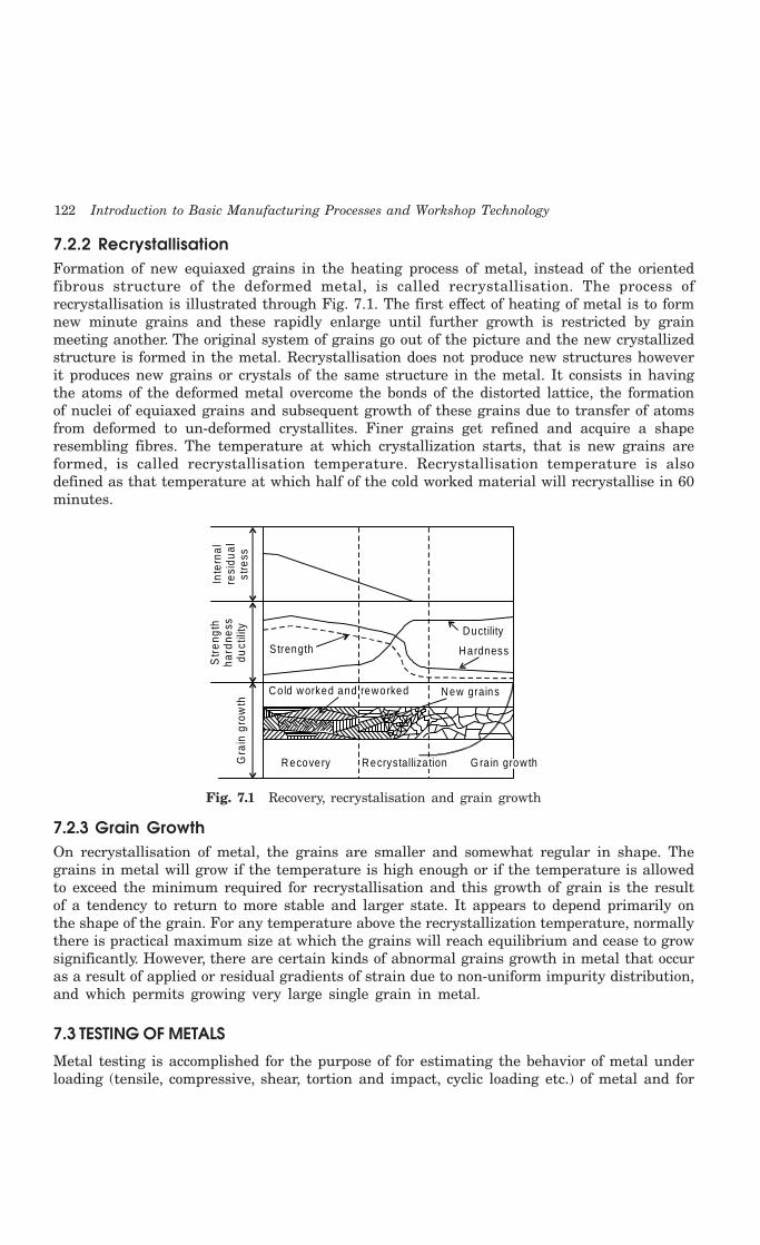
122 Introduction to Basic Manufacturing Processes and Workshop Technology
7.2.2 RecrystallisationFormation of new equiaxed grains in the heating process of metal, instead of the orientedfibrous structure of the deformed metal, is called recrystallisation. The process ofrecrystallisation is illustrated through Fig. 7.1. The first effect of heating of metal is to formnew minute grains and these rapidly enlarge until further growth is restricted by grainmeeting another. The original system of grains go out of the picture and the new crystallizedstructure is formed in the metal. Recrystallisation does not produce new structures howeverit produces new grains or crystals of the same structure in the metal. It consists in havingthe atoms of the deformed metal overcome the bonds of the distorted lattice, the formationof nuclei of equiaxed grains and subsequent growth of these grains due to transfer of atomsfrom deformed to un-deformed crystallites. Finer grains get refined and acquire a shaperesembling fibres. The temperature at which crystallization starts, that is new grains areformed, is called recrystallisation temperature. Recrystallisation temperature is alsodefined as that temperature at which half of the cold worked material will recrystallise in 60minutes.
Inte
rnal
resi
dual
stre
ss
Str
engt
hha
rdne
ssdu
ctili
tyG
rain
gro
wth
S trength
Ductility
Hardness
Co ld worked and reworked
Recovery
New grains
Recrystalliza tion G ra in grow th
Fig. 7.1 Recovery, recrystalisation and grain growth
7.2.3 Grain GrowthOn recrystallisation of metal, the grains are smaller and somewhat regular in shape. Thegrains in metal will grow if the temperature is high enough or if the temperature is allowedto exceed the minimum required for recrystallisation and this growth of grain is the resultof a tendency to return to more stable and larger state. It appears to depend primarily onthe shape of the grain. For any temperature above the recrystallization temperature, normallythere is practical maximum size at which the grains will reach equilibrium and cease to growsignificantly. However, there are certain kinds of abnormal grains growth in metal that occuras a result of applied or residual gradients of strain due to non-uniform impurity distribution,and which permits growing very large single grain in metal.
7.3 TESTING OF METALS
Metal testing is accomplished for the purpose of for estimating the behavior of metal underloading (tensile, compressive, shear, tortion and impact, cyclic loading etc.) of metal and for

Porperties and Testing of Metals 123
providing necessary data for the product designers, equipment designers, tool and die designersand system designers. The material behavior data under loading is used by designers fordesign calculations and determining weather a metal can meet the desired functionalrequirements of the designed product or part. Also, it is very important that the materialshall be tested so that their mechanical properties especially their strength can be assessedand compared. Therefore the test procedure for developing standard specification of materialshas to be evolved. This necessitates both destructive and non-destructive testing of materials.Destructive tests of metal include various mechanical tests such as tensile, compressive,hardness, impact, fatigue and creep testing. A standard test specimen for tensile test isshown in Fig. 7.2. Non-destructive testing includes visual examination, radiographic tests,ultrasound test, liquid penetrating test and magnetic particle testing.
Shou lderLength G auge
Length
R
R = Fillet Rad ius D = D iam eter
Fig. 7.2 Tensile test specimen
7.3.1 Tensile testA tensile test is carried out on standard tensile test specimen in universal testing machine.Fig. 7.3 shows a schematic set up of universal testing machine reflecting the testspecimen griped between two cross heads. Fig. 7.4 shows the stress strain curve forductile material. Fig. 7.5 shows the properties of a ductile material. Fig. 7.6 shows thestress strain curves for wrought iron and steels. Fig. 7.7 shows the stress strain curvefor non ferrous material.
Upper C rossHead
TestSpecim en
O pera ting Hand W hee l
LockingL iver
Ad justab leCross Head
Square ThreadedScrews
O pera ting HandW heel
Strain G auge orExtensionm eter
Co lumn
A B
C
DE
Str
ess
S train
A – L im it of p roportiona lityB – E lastic lim itC – Yield pointD – M aximum stress poin tE – B reaking o f fractu re point
Fig. 7.3 Schematic universal testing machine Fig. 7.4 Stress strain curve for ductile material

124 Introduction to Basic Manufacturing Processes and Workshop Technology
Elastic
Soft
Hard
Brittle Tough
Strong
D
E
W eak
R ig id
Str
ess
S train
Fig. 7.5 Properties of a ductile material
Too l S tee l
C rucible S tee l
M ed ium Steel
M ild S tee l
W rought Iron
Ste
ss
S train
Hard BrassAnnealed Brass
Ro lled A lum in ium
Strain
Str
ess
Ro lled Annealed Copper
A lum inum Bronze
Fig. 7.6 Stress strain curves for wrought Fig. 7.7 Stress strain curves for non-ferrous material iron and steel
7.3.2 Compression TestCompression test is reverse of tensile test. This test can also be performed on a universaltesting machine. In case of compression test, the specimen is placed bottom crossheads. Afterthat, compressive load is applied on to the test specimen. This test is generally performed fortesting brittle material such as cast iron and ceramics etc. Fig. 7.8 shows the schematiccompression test set up on a universal testing machine. The following terms have beendeduced using figures pertaining to tensile and compressive tests of standard test specimen.
Hook’s Law
Hook’s law states that when a material is loaded within elastic limit (up to proportionallimit), stress is proportional to strain.
StrainStrain is the ratio of change in dimension to the original dimension.

Porperties and Testing of Metals 125
LockingLever
LowerCross-Head
Column
Square Threaded Screw
CompressionPlates
Beds
Tab leTest P iece
HandW heel
Fig. 7.8 Schematic compression test set up on a universal testing machine
Tensile Strain
The ratio of increase in length to the original length is known as tensile strain.
Compressive Strain
The ratio of decrease in length to the original length is known as compressive strain.
Modulus of Elasticity
The ratio of tensile stress to tensile strain or compressive stress to compressive strain iscalled modulus of elasticity. It is denoted by E. It is also called as Young’s modulus of elasticity.
E = Tensile Stress/Tensile Strain
Modulus of Rigidity
The ratio of sheer stress to shear strain is called modulus of rigidity. It is denoted by G.
G = Shear Stress/Shear Strain
Bulk Modulus
The ratio of direct stress to the volumetric strain (ratio of change in volume to theoriginal volume is known as volumetric strain) is called Bulk modulus (denoted by K).
K = Direct stress/volumetric strain
Linear and Lateral Strain
When a body is subjected to tensile force its length increases and the diameter decreases.So when a test specimen of metal is stressed, one deformation is in the direction of forcewhich is called linear strain and other deformation is perpendicular to the force called lateralstrain.
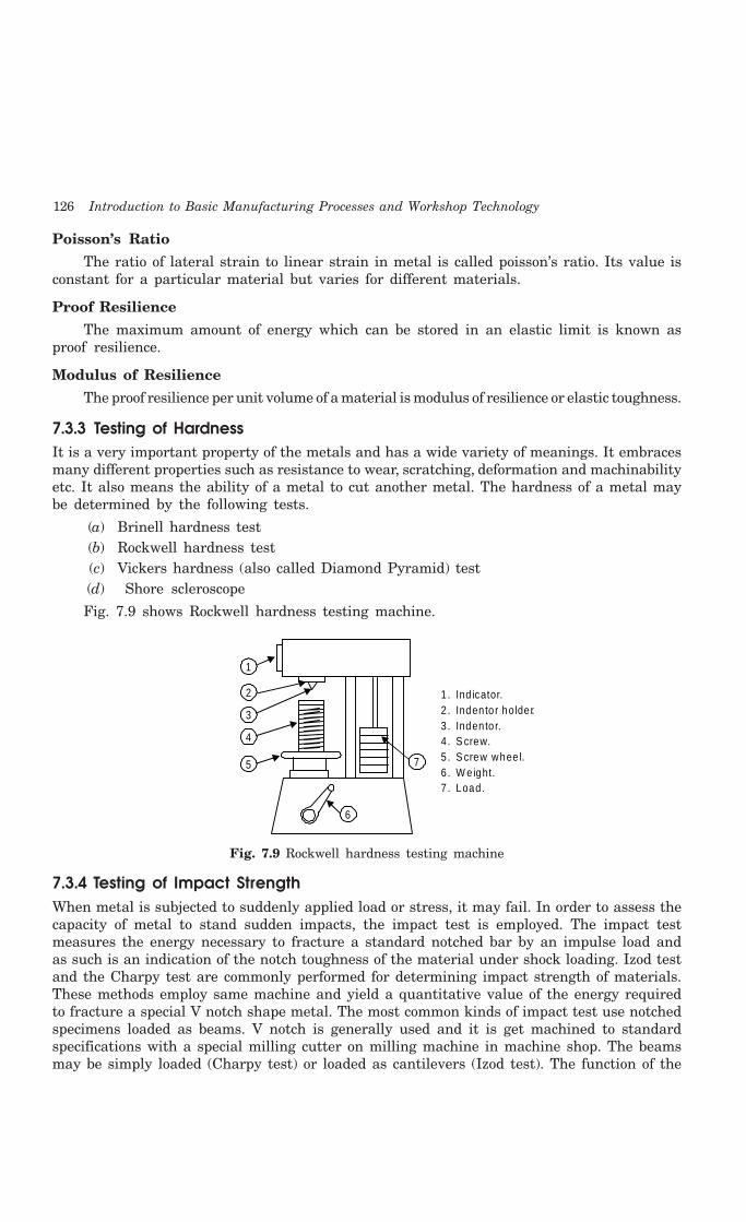
126 Introduction to Basic Manufacturing Processes and Workshop Technology
Poisson’s Ratio
The ratio of lateral strain to linear strain in metal is called poisson’s ratio. Its value isconstant for a particular material but varies for different materials.
Proof Resilience
The maximum amount of energy which can be stored in an elastic limit is known asproof resilience.
Modulus of Resilience
The proof resilience per unit volume of a material is modulus of resilience or elastic toughness.
7.3.3 Testing of HardnessIt is a very important property of the metals and has a wide variety of meanings. It embracesmany different properties such as resistance to wear, scratching, deformation and machinabilityetc. It also means the ability of a metal to cut another metal. The hardness of a metal maybe determined by the following tests.
(a) Brinell hardness test(b) Rockwell hardness test(c) Vickers hardness (also called Diamond Pyramid) test(d) Shore scleroscope
Fig. 7.9 shows Rockwell hardness testing machine.
1
2
3
4
5
6
7
1. Ind icator.2 . Indento r holder.3 . Indento r.4 . S crew.5 . S crew whee l.6 . W e ight.7 . Load.
Fig. 7.9 Rockwell hardness testing machine
7.3.4 Testing of Impact StrengthWhen metal is subjected to suddenly applied load or stress, it may fail. In order to assess thecapacity of metal to stand sudden impacts, the impact test is employed. The impact testmeasures the energy necessary to fracture a standard notched bar by an impulse load andas such is an indication of the notch toughness of the material under shock loading. Izod testand the Charpy test are commonly performed for determining impact strength of materials.These methods employ same machine and yield a quantitative value of the energy requiredto fracture a special V notch shape metal. The most common kinds of impact test use notchedspecimens loaded as beams. V notch is generally used and it is get machined to standardspecifications with a special milling cutter on milling machine in machine shop. The beamsmay be simply loaded (Charpy test) or loaded as cantilevers (Izod test). The function of the
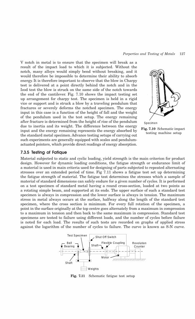
Porperties and Testing of Metals 127
V notch in metal is to ensure that the specimen will break as aresult of the impact load to which it is subjected. Without thenotch, many alloys would simply bend without breaking, and itwould therefore be impossible to determine their ability to absorbenergy. It is therefore important to observe that the blow in Charpytest is delivered at a point directly behind the notch and in theIzod test the blow is struck on the same side of the notch towardsthe end of the cantilever. Fig. 7.10 shows the impact testing setup arrangement for charpy test. The specimen is held in a rigidvice or support and is struck a blow by a traveling pendulum thatfractures or severely deforms the notched specimen. The energyinput in this case is a function of the height of fall and the weightof the pendulum used in the test setup. The energy remainingafter fracture is determined from the height of rise of the pendulumdue to inertia and its weight. The difference between the energyinput and the energy remaining represents the energy absorbed bythe standard metal specimen. Advance testing setups of carrying outsuch experiments are generally equipped with scales and pendulum-actuated pointers, which provide direct readings of energy absorption.
7.3.5 Testing of FatiqueMaterial subjected to static and cyclic loading, yield strength is the main criterion for productdesign. However for dynamic loading conditions, the fatigue strength or endurance limit ofa material is used in main criteria used for designing of parts subjected to repeated alternatingstresses over an extended period of time. Fig 7.11 shows a fatigue test set up determiningthe fatigue strength of material. The fatigue test determines the stresses which a sample ofmaterial of standard dimensions can safely endure for a given number of cycles. It is performedon a test specimen of standard metal having a round cross-section, loaded at two points asa rotating simple beam, and supported at its ends. The upper surface of such a standard testspecimen is always in compression and the lower surface is always in tension. The maximumstress in metal always occurs at the surface, halfway along the length of the standard testspecimen, where the cross section is minimum. For every full rotation of the specimen, apoint in the surface originally at the top centre goes alternately from a maximum in compressionto a maximum in tension and then back to the same maximum in compression. Standard testspecimens are tested to failure using different loads, and the number of cycles before failureis noted for each load. The results of such tests are recorded on graphs of applied stressagainst the logarithm of the number of cycles to failure. The curve is known as S-N curve.
Test S pecim en
BallBearing
Shaft
Shaft
Shut O ff Sw itch
W eigh ts
M otor
Flex ib le Coup ling Revo lu tionCounter
Fig. 7.11 Schematic fatigue test setup
Specim en
Fig. 7.10 Schematic impact testing machine setup
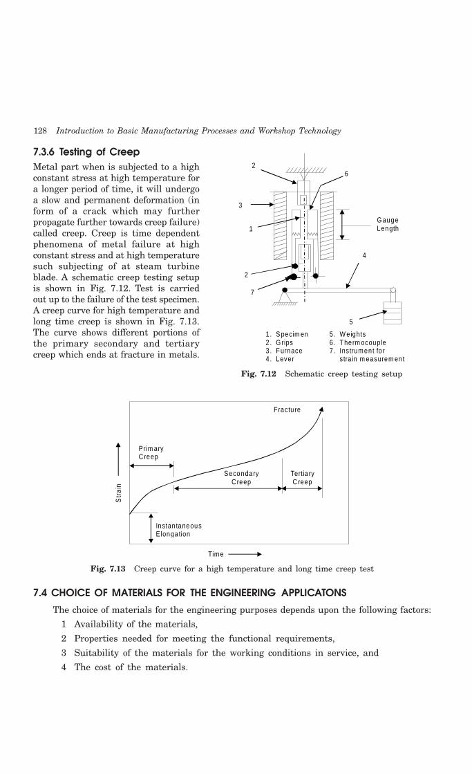
128 Introduction to Basic Manufacturing Processes and Workshop Technology
7.3.6 Testing of CreepMetal part when is subjected to a highconstant stress at high temperature fora longer period of time, it will undergoa slow and permanent deformation (inform of a crack which may furtherpropagate further towards creep failure)called creep. Creep is time dependentphenomena of metal failure at highconstant stress and at high temperaturesuch subjecting of at steam turbineblade. A schematic creep testing setupis shown in Fig. 7.12. Test is carriedout up to the failure of the test specimen.A creep curve for high temperature andlong time creep is shown in Fig. 7.13.The curve shows different portions ofthe primary secondary and tertiarycreep which ends at fracture in metals.
Prim aryCreep
SecondaryCreep
Tertia ryCreep
Fractu re
Instan taneousElongation
Time
Str
ain
Fig. 7.13 Creep curve for a high temperature and long time creep test
7.4 CHOICE OF MATERIALS FOR THE ENGINEERING APPLICATONS
The choice of materials for the engineering purposes depends upon the following factors:
1 Availability of the materials,
2 Properties needed for meeting the functional requirements,
3 Suitability of the materials for the working conditions in service, and
4 The cost of the materials.
2
3
1
2
7
4
5
6
G augeLength
1 . S pecim en2. G rips3 . Furnace4. Lever
5 . W e ights6 . Therm ocoup le7 . Instrument fo r s tra in m easurem ent
Fig. 7.12 Schematic creep testing setup
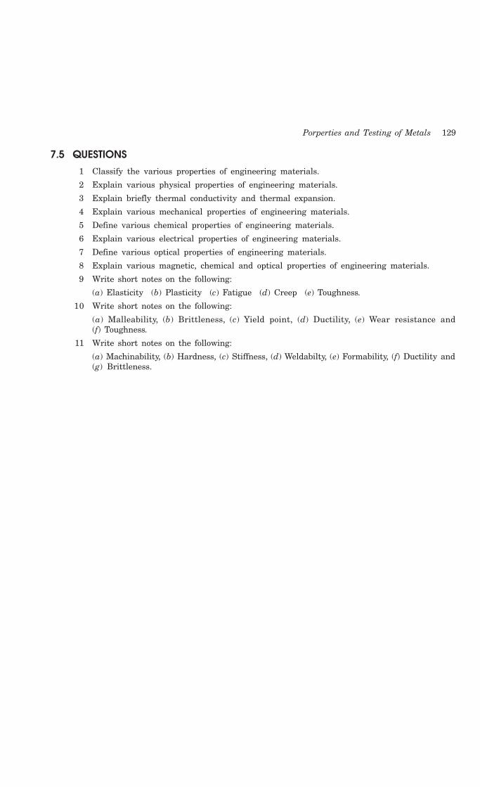
Porperties and Testing of Metals 129
7.5 QUESTIONS1 Classify the various properties of engineering materials.
2 Explain various physical properties of engineering materials.
3 Explain briefly thermal conductivity and thermal expansion.
4 Explain various mechanical properties of engineering materials.
5 Define various chemical properties of engineering materials.
6 Explain various electrical properties of engineering materials.
7 Define various optical properties of engineering materials.
8 Explain various magnetic, chemical and optical properties of engineering materials.
9 Write short notes on the following:
(a) Elasticity (b) Plasticity (c) Fatigue (d) Creep (e) Toughness.
10 Write short notes on the following:
(a) Malleability, (b) Brittleness, (c) Yield point, (d) Ductility, (e) Wear resistance and(f) Toughness.
11 Write short notes on the following:
(a) Machinability, (b) Hardness, (c) Stiffness, (d) Weldabilty, (e) Formability, (f) Ductility and(g) Brittleness.
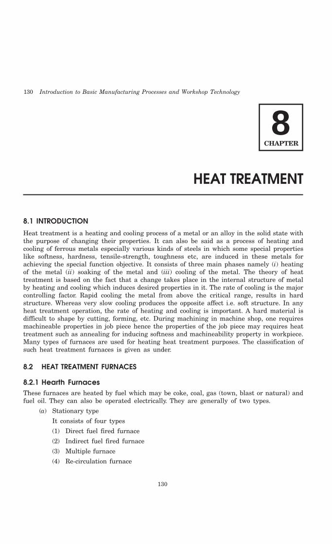
130 Introduction to Basic Manufacturing Processes and Workshop Technology
130
HEAT TREATMENT
8.1 INTRODUCTION
Heat treatment is a heating and cooling process of a metal or an alloy in the solid state withthe purpose of changing their properties. It can also be said as a process of heating andcooling of ferrous metals especially various kinds of steels in which some special propertieslike softness, hardness, tensile-strength, toughness etc, are induced in these metals forachieving the special function objective. It consists of three main phases namely (i) heatingof the metal (ii) soaking of the metal and (iii) cooling of the metal. The theory of heattreatment is based on the fact that a change takes place in the internal structure of metalby heating and cooling which induces desired properties in it. The rate of cooling is the majorcontrolling factor. Rapid cooling the metal from above the critical range, results in hardstructure. Whereas very slow cooling produces the opposite affect i.e. soft structure. In anyheat treatment operation, the rate of heating and cooling is important. A hard material isdifficult to shape by cutting, forming, etc. During machining in machine shop, one requiresmachineable properties in job piece hence the properties of the job piece may requires heattreatment such as annealing for inducing softness and machineability property in workpiece.Many types of furnaces are used for heating heat treatment purposes. The classification ofsuch heat treatment furnaces is given as under.
8.2 HEAT TREATMENT FURNACES
8.2.1 Hearth FurnacesThese furnaces are heated by fuel which may be coke, coal, gas (town, blast or natural) andfuel oil. They can also be operated electrically. They are generally of two types.
(a) Stationary type
It consists of four types
(1) Direct fuel fired furnace
(2) Indirect fuel fired furnace
(3) Multiple furnace
(4) Re-circulation furnace
8CHAPTER

Heat Treatment 131
(b) Movable type
It consists of two types(1) The car bottom type(2) The rotary type
8.2.2 Bath FurnacesIn bath type furnaces, heating may be done using by gas, oil or electricity. These furnacesare further classified as:
(1) Liquid bath type(2) Salt bath type(3) Lead bath type(4) Oil bath type
8.3 CONSTITUENTS OF IRON AND STEEL
Fig. 8.1 shows micro structure of mild steel (0.2-0.3% C). White constituent in this figure is verypure iron or having very low free carbon in iron in form of ferrite and dark patches containcarbon in iron is chemically combined form known as carbide (Cementite). Cementite is veryhard and brittle. Now if the dark patches of the above figure are further observed, a substancebuilt up of alternate layer of light and dark patches is reflected in Fig. 8.2. These layers arealternatively of ferrite and cementite. This substance is called as pearlite and is made up of 87%ferrite and 13% cementite. But with increase of carbon content in steel portion of pearliteincreases up to 0.8% C. The structure of steel at 0.8% C is entirely of pearlite. However if carboncontent in steel is further increased as free constituent up to 1.5% C, such steel will be calledas high carbon steel. The micro structure of high carbon steel is depicted in Fig. 8.3.
CementiteAreas
FerriteCrystals
Fig. 8.1 Micro structure of mild steel Fig. 8.2 Micro structure of Fig. 8.3 Micro structure of pearlitic eutectoid steel of high carbon steel
8.4 ALLOTROPY OF IRON
In actual practice it is very difficult to trace the cooling of iron from 1600°C to ambienttemperature because particular cooling rate is not known. Particular curve can be tracedfrom temperature, time and transformation (TTT) curve. However allotropic changes observedduring cooling of pure iron are depicted in Fig. 8.4. When iron is cooled from molten conditionup to the solid state, the major allotropic changing occurs which are:
1539-1600°C Molten-Fe (Liquid state of iron)1400-1539°C Delta-Fe (Body centered)
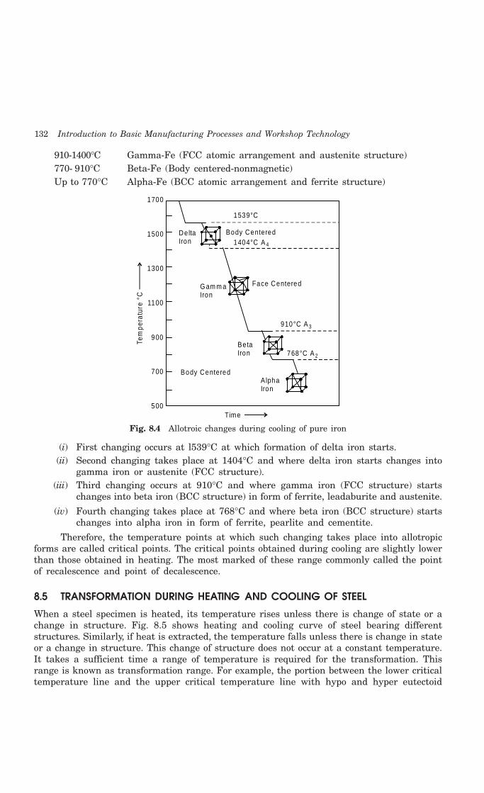
132 Introduction to Basic Manufacturing Processes and Workshop Technology
910-1400°C Gamma-Fe (FCC atomic arrangement and austenite structure)770- 910°C Beta-Fe (Body centered-nonmagnetic)Up to 770°C Alpha-Fe (BCC atomic arrangement and ferrite structure)
1700
1500
1300
1100
900
700
500Time
Tem
pera
ture
°C
1539°C
Body Centered1404°C A 4
Face CenteredG am m aIron
910°C A 3
768°C A 2
AlphaIron
BetaIron
Body Centered
De ltaIron
Fig. 8.4 Allotroic changes during cooling of pure iron
(i) First changing occurs at l539°C at which formation of delta iron starts.(ii) Second changing takes place at 1404°C and where delta iron starts changes into
gamma iron or austenite (FCC structure).(iii) Third changing occurs at 910°C and where gamma iron (FCC structure) starts
changes into beta iron (BCC structure) in form of ferrite, leadaburite and austenite.
(iv) Fourth changing takes place at 768°C and where beta iron (BCC structure) startschanges into alpha iron in form of ferrite, pearlite and cementite.
Therefore, the temperature points at which such changing takes place into allotropicforms are called critical points. The critical points obtained during cooling are slightly lowerthan those obtained in heating. The most marked of these range commonly called the pointof recalescence and point of decalescence.
8.5 TRANSFORMATION DURING HEATING AND COOLING OF STEEL
When a steel specimen is heated, its temperature rises unless there is change of state or achange in structure. Fig. 8.5 shows heating and cooling curve of steel bearing differentstructures. Similarly, if heat is extracted, the temperature falls unless there is change in stateor a change in structure. This change of structure does not occur at a constant temperature.It takes a sufficient time a range of temperature is required for the transformation. Thisrange is known as transformation range. For example, the portion between the lower criticaltemperature line and the upper critical temperature line with hypo and hyper eutectoid

Heat Treatment 133
steels, in iron carbon equilibrium diagram. This range is also known as critical range. Overheating for too long at a high temperature may lead to excessive oxidation or decarburizationof the surface. Oxidation may manifest itself in the form of piece of scale which may be driveninto the surface at the work piece if it is going to be forged. If steel is heated, well above theupper critical temperature, large austenite grains form. In other words steel developsundesirable coarse grains structure if cooled slowly to room temperature and it lacks both inductility and resistance to shock.
M olten IronAusten ite
Austen ite 0 .5% C
Austen iteFerrite
Pearlite
Ferrite
E
D
C
A BAB
C800
721
1340
1505
Tem
pera
ture
°C
D
E
Time Time
Fig. 8.5 Heating and cooling curve of steel
8.6 IRON-CARBON EQUILIBRIUM DIAGRAM
Fig. 8.6 shows, the Fe-C equilibrium diagram in which various structure (obtained duringheating and cooling), phases and microscopic constituents of various kinds of steel and castiron are depicted. The main structures, significance of various lines and critical points arediscussed as under.
8.6.1 Structures in Fe-C-diagramThe main microscopic constituents of iron and steel are as follows:
1. Austenite
2. Ferrite
3. Cementite
4. Pearlite

134 Introduction to Basic Manufacturing Processes and Workshop Technology
1600
1500
1400
1300
1200
1100
1000
900
800
723
600
500
400
300
200
100
01 2 3 4 4.3 5 6 6.7
Fe +Pear-lite
Pearlite+
Cementite
Cementite+
Pearlite+
Ledeburite
Cast Iron
Cementite+
Ledeburite
Stee l
Hypo-eutectoid
Hyper-eutectoid
Carbon Percentage
Austen ite+
Cementite
Eutectoid
0 .025%Carbon700
A 1
Austen ite+
Ledeburite
So lidus
1130°Eutectic
Cementite+
LedeburiteAcm
Fe+A ustenite( + )α γG
Austen ite-ironγ
Solidus (Austen ite)
EC
L iquidus
δ-Iron+
Austen ite
t2H J
t1 B
δ Fe + liquid
δ iron A
γ S olid So lutioncrysta ls
L iquid
L iquid+
Cementite
A 3
P S
D
F
K
Tem
per
atu
re°C
Q 0.8
α-IronFe
t4
t3
Fig. 8.6 Fe-C equilibrium diagram
8.6.1.1 Austenite
Austenite is a solid solution of free carbon (ferrite) and iron in gamma iron. On heatingthe steel, after upper critical temperature, the formation of structure completes into austenitewhich is hard, ductile and non-magnetic. It is able to dissolve large amount of carbon. It isin between the critical or transfer ranges during heating and cooling of steel. It is formedwhen steel contains carbon up to 1.8% at 1130°C. On cooling below 723°C, it starts transforminginto pearlite and ferrite. Austenitic steels cannot be hardened by usual heat treatment methodsand are non-magnetic.

Heat Treatment 135
8.6.1.2 Ferrite
Ferrite contains very little or no carbon in iron. It is the name given to pure iron crystalswhich are soft and ductile. The slow cooling of low carbon steel below the critical temperatureproduces ferrite structure. Ferrite does not harden when cooled rapidly. It is very soft andhighly magnetic.
8.6.1.3 Cementite
Cementite is a chemical compound of carbon with iron and is known as iron carbide(Fe3C). Cast iron having 6.67% carbon is possessing complete structure of cementite. Freecementite is found in all steel containing more than 0.83% carbon. It increases with increasein carbon % as reflected in Fe-C Equilibrium diagram. It is extremely hard. The hardnessand brittleness of cast iron is believed to be due to the presence of the cementite. Itdecreases tensile strength. This is formed when the carbon forms definite combinationswith iron in form of iron carbides which are extremely hard in nature. The brittleness andhardness of cast iron is mainly controlled by the presence of cementite in it. It is magneticbelow 200°C.
8.6.1.4 Pearlite
Pearlite is a eutectoid alloy of ferrite and cementite. It occurs particularly in medium andlow carbon steels in the form of mechanical mixture of ferrite and cementite in the ratio of87:13. Its hardness increases with the proportional of pearlite in ferrous material. Pearlite isrelatively strong, hard and ductile, whilst ferrite is weak, soft and ductile. It is built up ofalternate light and dark plates. These layers are alternately ferrite and cementite. When seenwith the help of a microscope, the surface has appearance like pearl, hence it is calledpearlite. Hard steels are mixtures of pearlite and cementite while soft steels are mixtures offerrite and pearlite.
As the carbon content increases beyond 0.2% in the temperature at which the ferrite isfirst rejected from austenite drop until, at or above 0.8% carbon, no free ferrite is rejectedfrom the austenite. This steel is called eutectoid steel, and it is the pearlite structure incomposition.
As iron having various % of carbon (up to 6%) is heated and cooled, the following phasesrepresenting the lines will tell the about the structure of iron, how it charges.
8.6.2 Significance of Transformations Lines
Line ABCD
The line ABCD tells that above this line melting has been completed during heating theiron. The molten metal is purely in the liquidus form. Below this line and above line AHJECFthe metal is partially solid and partially liquid. The solid metal is known as austenite. Thusthe line ABCD represents temperatures at which melting is considered as completed. Beyondthis line metal is totally in molten state. It is not a horizontal line the melting temperaturewill vary with carbon content.
Line AHJECF
This line tells us that metal starts melting at this temperature. This line is not horizontaland hence the melting temperatures will change with carbon content. Below this line andabove line GSEC, the metal is in solid form and having austenite structure.

136 Introduction to Basic Manufacturing Processes and Workshop Technology
Line PSK
This line occurs near 723°C and is a horizontal line and is known as lower criticaltemperature line because transformation of steels starts at, this line. Carbon % has not effecton it that means steel having different % of carbon will transforms at the same temperature.The range above the line up to GSE is known as transformation range. This line tells us thesteel having carbon up to 0.8% up to 0.8% will starts transforming from ferrite and pearliteto austenite during heating.
Line ECF
It is a line at temperature 1130°C which tells that for cast iron having % of C from 2%to 4.3%. Below this line and above line SK, Cast iron will have austenite + ledeburite andcementite + ledeburite.
8.6.3 Critical TemperaturesThe temperatures at which changes in structure takes place is known as critical temperatures,these are as follows:
1. The temperature along GSE is known as upper critical temperature. Thetemperature along GS during heating as (upper critical temperature) where austenite+ alpha iron changes into austenite and vice versa.
2. The temperature along GS during cooling as A3 where austenite changes intoaustenite + alpha iron and vice versa during heating.
3. The temperature along line SE during heating as Acm changes into austenite fromaustenite + cementite and vice versa.
4. The temperature along PSK is known as lower critical temperature whenpearlite changes into austenite on heating as denoted, by A1.
8.6.2 Objectives of Heat TreatmentThe major objectives of heat treatment are given as under
1. It relieves internal stresses induced during hot or cold working.
2. It changes or refines grain size.
3. It increases resistance to heat and corrosion.
4. It improves mechanical properties such as ductility, strength, hardness, toughness,etc.
5. It helps to improve machinability.
6. It increases wear resistance
7. It removes gases.
8. It improves electrical and magnetic properties.
9. It changes the chemical composition.
10. It helps to improve shock resistance.
11. It improves weldability.
The above objectives of heat treatment may be served by one or more of the followingheat treatment processes:

Heat Treatment 137
1. Normalizing2. Anne aling.3. Hardening.4. Tempering5. Case hardening
(a) Carburizing(b) Cyaniding(c) Nitriding
6. Surface hardening(a) Induction hardening,(b) Flame hardening.
Fig. 8.7 shows the heating temperature ranges for various heat treatment processes.
Carbon percentage
Hyper-eutectoid stee l
Pea
rlite
Sphero idis ing
A Lower critica lrange 723°C
C 3
Austen ite ( -Fe)γ
Norm aliz ing
Annealing
Hardening
A 1130°C
cm
A Upper critica l range
C 1
Ferrite
Processannea ling
H ightem peraturetem pering
Ferrite + P earlite
Lowtem peraturetem pering
Hypo-eutectoid stee l
1200
1100
1000
900
800
700
600
500
400
300
200
100
0.2 0 .4 0 .6 0 .8 1 .0 1 .5 2 .0
Pearlite + Cementite
Tem
pera
ture
°C
Fig. 8.7 Heating temperature ranges for various heat treatment processes
8.8 NORMALIZING
Normalizing is a defined as softening process in which iron base alloys are heated 40 to 50°Cabove the upper-critical limit for both hypo and hyper eutectoid steels and held there for aspecified period and followed by cooling in still air up to room temperature. Fig 8.7 shows the

138 Introduction to Basic Manufacturing Processes and Workshop Technology
heating temperature ranges for normalizing process of both hypo and hyper carbon steel.Fig. 8.8 shows the structure obtained after normalizing of medium carbon steel.
Objectives1. To soften metals2. Refine grain structure3. Improve machinability after forging and rolling4. improve grain size5. Improve structure of weld6. Prepare steel for sub heat treatment
8.9 ANNEALING
It is a softening process in which iron base alloys are heated above the transformation rangeheld there for proper time and then cool slowly (at the of rate of 30 to 150°C per hour) belowthe transformation range in the furnace itself. Heating is carried out 20°C above upper criticaltemperature point of steel in case of hypo eutectoid steel and the same degree above thelower critical temperature point in case of type eutectoid steel. Fig 8.7 shows the heatingtemperature ranges for annealing or softening process of both hypo and hyper carbon steel.Fig. 8.9 shows the structure obtained after annealing of medium carbon steel. The structureof steel on slow cooling changes into ferrite and pearlite for hypo eutectoid steel, pearlite foreutectoid steel and pearlite and cementite for hyper eutectoid steel. The time for holding thearticle in furnace is ½ to 1 hour. As ferrous metals are heated above the transformationrange, austenite structure will be attained at this temperature.
For a particular type of structure specific cooling rate is required to have good annealingproperties for free machining. As metal is slowly cooled after heating and holding in and withthe furnace and buried in non conducting media such sand, lime or ashes, carbon steels arecooled down at particular rate normally 150-200°C per hour while alloy steel in which austeniteis very stable and should be cooled much lower (30°C to 100°C per hour). Very slow coolingis required in annealing to enable austenite to decompose at two degrees of super cooling soas to form a pearlite and ferrite structure in hypo-eutectoid steel, a pearlite structure ineutectoid steel and pearlite and cementite structure in hyper eutectoid steel. In successfullyannealed steel, the grains of ferrite are large and regular while pearlite consists of cementiteand ferrite. Hypo-eutectoid hot worked steel may under go full annealing to obtain coarsegrain structure for free machining. When steel is cold worked the hardness (Brinell hard)considerably increases and ductility decreases slightly. The ductility of steel may be thenrestored by so called recrystallisation or process annealing.
8.9.1 Objectives of AnnealingThe purpose of annealing is to achieve the following
1. Soften the steel.2. Relieve internal stresses3. Reduce or eliminate structural in-homogeneity.4. Refine grain size.5. Improve machinability.
6. Increase or restore ductility and toughness.

Heat Treatment 139
Annealing is of two types
(a) Process annealing
(b) Full annealing.
In process annealing, ductility is increased with somewhat decrease in internal stresses.In this, metal is heated to temperature some below or close to the lower critical temperaturegenerally it is heated 550°C to 650°C holding at this temperature and it is slowly cooled. Thiscauses completely recrystallisation in steel.
The main purpose of full annealing of steel is to soften it and to refine its grainstructure. In this, the hypo-eutectoid steel is heated to a temperature approximately 20°to 30°C above the higher critical temperature and for hypereutectoid steel and tool steelis heated to a temperature 20 to 30°C above the lower critical temperature and thistemperature is maintained for a definite time and then slowly cooed very slow1y in thefurnace itself.
8.10 SPHEROIDIZATION
It is lowest temperature range of annealing process in which iron base alloys are heated 20to 40°C below the lower critical temperature, held therefore a considerable period of time e.g.for 2.5 cm diameter piece the time recommended is four-hours. It is then allowed to cool veryslowly at room temperature in the furnace itself. Fig 8.7 shows the heating temperatureranges for spheroidizing process of carbon steel. Fig. 8.9 shows the structure obtained afterannealing of carbon steel. During this process, the cementite of steel which is in the combinedform of carbon becomes globular or spheroidal leaving ferrite in matrix, thus impartingsoftness to steel. After normalizing of steels, the hardness of the order of 229 BHN and assuch machining becomes difficult and hence to improve machining, these are spheroidisedfirst and then machined. This treatment is carried out on steels having 0.6 to 1.4% carbon.The objectives of spheroidising are given as under.
Ferrite Pearlite+
Fig. 8.8 Structure of normalized Fig. 8.9 Structure of annealed medium carbon steel medium carbon steel
1. To reduce tensile strength
2. To increase ductility
3. To ease machining
4. To impart structure for subsequent hardening process
8.11 COMPARISON BETWEEN ANNEALING AND NORMALISING
The comparison between annealing and normalizing is given as under in Table 8.1.

140 Introduction to Basic Manufacturing Processes and Workshop Technology
Table 8.1 Comparison between Annealing and Normalising
S.No. Annealing Normalising
1 In this hypo-eutectoid steel is heated to a In this metal is heated 30 to 50°C abovetemperature approximately 20 to 30°C above higher critical temperature.temperature the higher critical temperatureand for hypereutectoid steel is heated 20 to30°C above the lower critical temperature.
2 It gives good results for low and medium It also gives very good results for low andcarbon steel medium carbon steel
3 It gives high ductility It induces gives higher ultimate strength,yield point and impact strength in ferrousmaterial.
4 It is basically required to soften the metal, It is basically required to refine grain size,to improve machinability, to increase ductility, improve structure of weld, to relieveimprove, to refine grain size. internal stresses.
8.12 HARDENING
Hardening is a hardness inducing kind of heat treatment process in which steel is heated toa temperature above the critical point and held at that temperature for a definite time andthen quenched rapidly in water, oil or molten salt bath. It is some time said as rapidquenching also. Steel is hardened by heating 20-30°C above the upper critical point for hypoeutectoid steel and 20-30°C above the lower critical point for hyper eutectoid steel and heldat this temperature for some time and then quenched in water or oil or molten salt bath.Fig 8.7 shows the heating temperature ranges for hardening process of both hypo and hypercarbon steel. Fig. 8.10 (a) shows the structure obtained on water quenching on hardening ofmedium carbon steel. Fig. 8.10 (b) shows the structure obtained on oil quenching on hardeningof medium carbon steel. Fig. 8.10 (c) shows the structure obtained on water quenching onhardening of medium carbon steel and followed by tempering.
(a) (b) (c)
Fig. 8.10 Structure of hardened carbon steel
Metal is heated up to austenite formation and is followed by fast and continuous coolingof austenite to temperature 205° to 315°C or even lower than that. Due to such rapid cooling,austenitic structure changes to new structure known as martensite. It is evident that fasterthe rate of cooling harder will be the metal due to formation of more martensitic structure.Martensite has a tetragonal crystal structure. Hardness of martensite varies from 500 to 1000BHN depending upon the carbon content and fineness of the structure. Martensite is a bodycentered phase produced by entrapping carbon on decomposition of austenite when cooledrapidly. It is the main constituent of hardened steel. It is magnetic and is made of a needlelike fibrous mass. It has carbon content up to 2%. It is extremely hard and brittle. Thedecomposition of austenite below 320°C starts the formation of martensite.
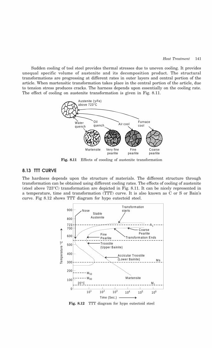
Heat Treatment 141
Sudden cooling of tool steel provides thermal stresses due to uneven cooling. It providesunequal specific volume of austenite and its decomposition product. The structuraltransformations are progressing at different rates in outer layers and central portion of thearticle. When martensitic transformation takes place in the central portion of the article, dueto tension stress produces cracks. The harness depends upon essentially on the cooling rate.The effect of cooling on austenite transformation is given in Fig. 8.11.
Waterquench
O ilquench Air coo l
Furnacecoo l
M artensite Very finepearlite
Finepearlite
Coarsepearlite
Austen ite above 723°C
( -Fe)γ
Fig. 8.11 Effects of coooling of austenite transformation
8.13 TTT CURVE
The hardness depends upon the structure of materials. The different structure throughtransformation can be obtained using different cooling rates. The effects of cooling of austenite(steel above 723°C) transformation are depicted in Fig. 8.11. It can be nicely represented ina temperature, time and transformation (TTT) curve. It is also known as C or S or Bain’scurve. Fig 8.12 shows TTT diagram for hypo eutectoid steel.
NoseTransfo rm ationstarts
Stab leAusten ite
900
800
723700
600
500
400
300
200
100
0
20°C
101 10 2 103 104 105 106
Time (Sec.)
A1
CoarsePearlite
Transfo rm ation EndsFinePearlite
Troostite(Upper Ba in ite)
Accicular Troostite(Lower Ba in ite) M s
M artensite
M 5 0
M 8 0
Tem
pera
ture
°C
M f
Fig. 8.12 TTT diagram for hypo eutectoid steel

142 Introduction to Basic Manufacturing Processes and Workshop Technology
Fig. 8.13 shows a series of cooling curves which result from different rates of coolingwhen superimposed on TTT curve. These curves reveal the decomposition of stable austeniteexisting above critical temperature in various forms during cooling depending upon the coolingrate. The transformation of austenite starts during suitable cooling. The minimum coolingrate required to produce martensite in given steel is determined by the position of the noseof the S curve. The cooling rate required to avoid the nose of the S curve is called the criticalcool. Any other cooling rate, faster than to that of the nose of S curve will cause completetransformation of austenite to martensite.
Beginn ing of fe rite p rec ip itationA + F
1333°F
95%
50%5%
A
(a)(b )
(c)(d ) (e )
tm in
(f)
Coarse pearliteM ed ium pearliteFine pearlite
Feathery ba in ite
Acicu la rbainite
M artensite
10410310210
Water O il A ir Furnace
65-60
50
103040
Tem
p.
600°F
300°F
Ro
ckw
ell (
R)
C
Stab le austim ite
Cooling Tim e (min.)
Fig. 8.13 Series of different cooling rates curves in TTT diagram
Assume a cooling rate ‘a’ achieved in water, this curve does not cut the nose of TTTcurve, and the pearlite transformation does not take place. However the resulting structureat room temperature is martensite. Cooling curve ‘c’ reflects that the cooling rate is slowerthan water and is in oil still lesser than the critical cooling rate, the curve ‘c’ will result inthe micro structure composed of martensite. Curve ‘d’ and curve ‘e’ corresponds to the rateof cooling during normalizing and annealing. The parts of austenite transform to fine andcoarse pearlite. The intermediate cooling rate curves ‘f ’ and ‘b’ higher than critical coolingrate results in the structure between pearlite and martensite known as feathery bannite andacicular (needles) bannite. Intermediate cooling rate is achieved by quenching or dipping theaustenite at two hot oil baths maintained at different temperature such as in case ofaustempering (f curve) and mar tempering (b curve). Those special cooling rate will formcoarse and fine bainite structure according the level of temperature of quenching.
Transformation of austenite to pearlite depends upon the temperature, time andtransformation curve. It relates the transformation of austenite to the time and temperatureconditions to which it is subjected. As metal is heated above the critical point austenite willform in the structure of metal if it is cooled slowly with respect to time. The structure wil1change to coarse pearlite and cementite placeless in a ferrite matrix due to transformation

Heat Treatment 143
of temperature and hence nuclei thus formed grow rapidly. Such as coarse laminar pearliteis relatively soft and is not very ductile. After this, if slightly faster cooling than above slowcooling is applied to austenite; coarse bainite structure will be formed.
8.14 TEMPERING
If high carbon steel is quenched for hardening in a bath, it becomes extra hard, extra brittleand has unequal distribution internal stresses and strain and hence unequal harness andtoughness in structure. These extra hardness, brittleness and unwanted induced stress andstrain in hardened metal reduce the usability the metal. Therefore, these undesired needs mustbe reduced for by reheating and cooling at constant bath temperature. In tempering, steel afterhardening, is reheated to a temperature below the lower critical temperature and then followedby a desired rate of cooling. Reheating the of hardened steel is done above critical temperaturewhen the structure is purely of austenite and then quenching it in a molten salt path havingtemperature in the range of 150-500°C. This is done to avoid transformation to ferrite andpearlite and is held quenching temperature for a time sufficient to give complete formation toan intermediate structure referred to as bainite then cooled to room temperature. Thetemperature should not be held less than 4 to 5 minutes for each millimeters of the section.After tempering structure is changed into secondary structure like martensite, troostite,sorbite and spheroidised. Fig. 8.14 shows different tempered states of martensite, troosite,sorbite and spherodite. Depending upon the temperature of reheat, the tempering process isgenerally classified in to three main categories. Which are discussed as under.
Spherod ite
Sorbite
Troosite
M artensite
Normalstate
A 1
1000
500
Tem
pera
ture
(°F
)
Austin ite( + Fe)γ
Fig. 8.14 Structures of tempered states of martensite, troosite, sorbite and spherodite
8.14.1 Low Temperature TemperingHardened steel parts requiring tempering are heated up to 200°C and then quenched in oil.Tempering is used to retain hard micro-structure of martensite which increases brittleness.Fig 8.15a represents the microstructure of martensite.
8.14.2 Medium Temperature TemperingHardened steel parts requiring tempering are heated in the temperature range of 200-350°C.This process gives troosite structure. Troosite structure is another constituent of steel obtainedby quenching tempering martensite. It is composed of the cementite phase in a ferrite matrixthat cannot be resolved by light microscope. It is less hard and brittle than martensite. It is
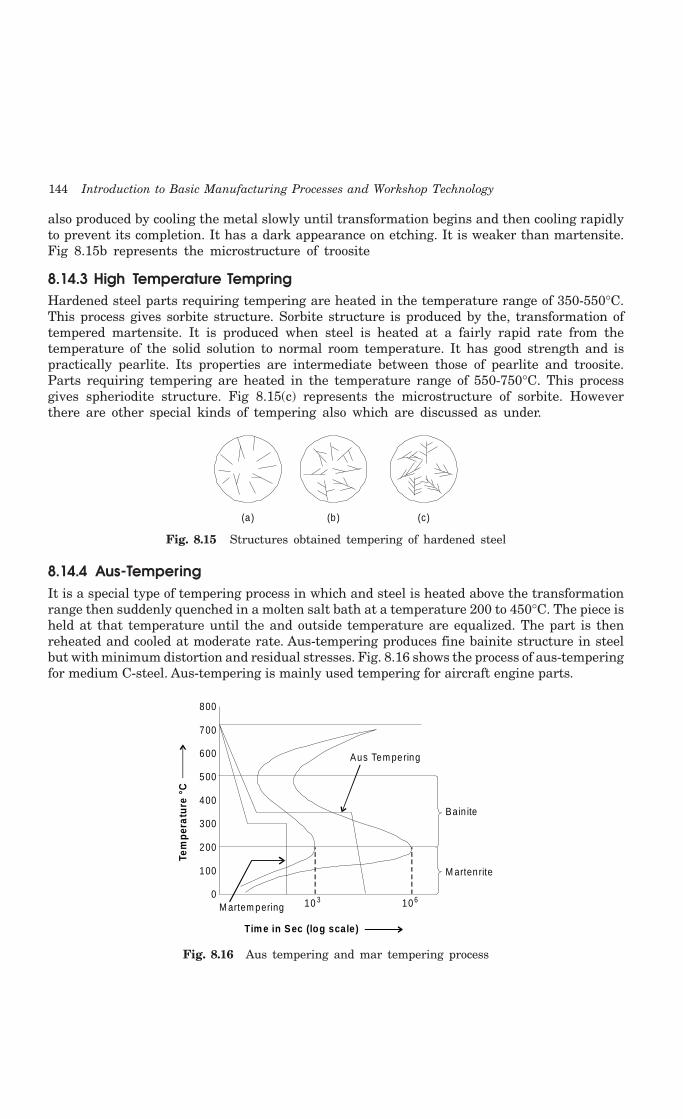
144 Introduction to Basic Manufacturing Processes and Workshop Technology
also produced by cooling the metal slowly until transformation begins and then cooling rapidlyto prevent its completion. It has a dark appearance on etching. It is weaker than martensite.Fig 8.15b represents the microstructure of troosite
8.14.3 High Temperature TempringHardened steel parts requiring tempering are heated in the temperature range of 350-550°C.This process gives sorbite structure. Sorbite structure is produced by the, transformation oftempered martensite. It is produced when steel is heated at a fairly rapid rate from thetemperature of the solid solution to normal room temperature. It has good strength and ispractically pearlite. Its properties are intermediate between those of pearlite and troosite.Parts requiring tempering are heated in the temperature range of 550-750°C. This processgives spheriodite structure. Fig 8.15(c) represents the microstructure of sorbite. Howeverthere are other special kinds of tempering also which are discussed as under.
(a ) (b ) (c)
Fig. 8.15 Structures obtained tempering of hardened steel
8.14.4 Aus-TemperingIt is a special type of tempering process in which and steel is heated above the transformationrange then suddenly quenched in a molten salt bath at a temperature 200 to 450°C. The piece isheld at that temperature until the and outside temperature are equalized. The part is thenreheated and cooled at moderate rate. Aus-tempering produces fine bainite structure in steelbut with minimum distortion and residual stresses. Fig. 8.16 shows the process of aus-temperingfor medium C-steel. Aus-tempering is mainly used tempering for aircraft engine parts.
800
700
600
500
400
300
200
100
0M artem pering 10 3 10 6
Ba in ite
M artenrite
Aus Tem pering
Tem
per
atu
re °
C
Tim e in Sec (log scale)
Fig. 8.16 Aus tempering and mar tempering process

Heat Treatment 145
Advantages of Aus-Tempering1. Quenching cracks are avoided.
2. Distortion and warping are avoided.
3. A more uniform microstructure is obtained.
4. Mechanical properties of bainite are superior to conventional hardening micro-structure.
Limitations of Aus-Tempering1. The process is very costly.
2. The process is time consuming.
8.14.5 Mar TemperingIt is a type of tempering process in which and its base alloys are heated above the transformationrange then suddenly quenched in a molten salt bath at a temperature 80 to 300°C. The pieceis held at that temperature until the and outside temperature are equalized. The part is thenreheated and cooled at moderate rate. Mar-tempering produces martensite in steel but withminimum distortion and residual stresses. Fig. 8.16 shows the mar tempering process formedium C-steel and its micro structures of given stages. Cold chisels are hardened at thecutting edge and followed by tempering. Because these processes increase the hardness ofchisel and increase the cutting ability.
8.15 CASE HARDENING
Some times special characteristic are required in metal such as hard outer surface and soft,tough and more strength oriented core or inner structure of metal. This can be obtained bycasehardening process. It is the process of carburization i.e. saturating the surface layer of steelwith carbon or some other substance by which outer case of the object is hardened where as thecore remains soft. It is applied to very low carbon steel. It is performed for obtaining hard andwear resistance on surface of metal and higher mechanical properties with higher fatigue, strengthand toughness in the core. The following are the case hardening process.
(1) Carburizing
(2) Nitriding.
(3) Cyaniding.
(4) Induction hardening.
(5) Flame hardening
These processes are discussed as under.
8.15.1 CarburizingCarburizing can be of three types
1. Pack carburizing
2. Liquid carburizing and
3. Gas carburizing
The above carburizing processes are discussed as under.

146 Introduction to Basic Manufacturing Processes and Workshop Technology
8.15.1.1 Pack Carburizing
Metals to be carburized such as low carbon steel is placed in cast iron or steel boxescontaining a rich material in carbon like charcoal, crushed bones, potassium Ferro-cyanideor charred leather. Such boxes are made of heat resisting steel which are then closed andsealed with clay. Long parts to be carburized are kept vertical in -boxes. The boxes are heatedto a temperature 900°C to 950°C according to type of steel for absorbing carbon on the outersurface. The carbon enters the on the metal to form a solid solution with iron and convertsthe outer surface into high carbon steel. Consequently pack hardened steel pieces havecarbon content up to 0.85% in their outer case. After this treatment, the carburized parts arecooled in boxes. Only plane carbon steel is carburized in this process for hardening the outerskin and refining the structure of the core to make it soft and tough. Small gears are casehardened by this process for which they are enclosed in the cast iron or steel box containinga material rich in carbon, such as small piece of charcoal and then heat to a temperatureslightly above the critical range. Depth of hardness from 0.8-1.6 mm is attained in three tofour hours. The gears are then allowed to cool slowly with-in the box and then removed. Thesecond stage consists of reheating the gears (so obtained) to about 900°C and then quenchedin oil so that its structure is refined, brittleness removed and the core becomes soft andtough. The metal is then reheated to about 700°C and quenched in water so that outer surfaceof gear, which had been rendered soft during the preceding operation, is again hardened.
8.15.1.2 Liquid Carburizing
Liquid carburizing is carried out in a container filled with a molten salt, such as sodiumcyanide. This bath is heated by electrical immersion elements or by a gas burner and stirringis done to ensure uniform temperature. This process gives a thin hardened layer up to 0.08mm thickness. Parts which are to be case-hardened are dipped into liquid bath solutioncontaining calcium cyanide and polymerized hydro-cyanide acid or sodium or potassium cyanidealong-with some salt. Bath temperature is kept from 815°C to 900°C. The furnace is usuallycarbon steel case pot which may be by fired by oil, gas or electrically. If only selected portionsof the components are to be carburized, then the remaining portions are covered by copperplating. There are some advantages of the liquid bath carburizing which are given as under.
Advantages
1. Greater depth of penetration possible in this process.
2. Selective carburizing is possible if needed.
3. Uniform heating will occur in this process.
4. Little deformation or distortion of articles occur in this process.
5. Ease of carburizing for a wider range of products.
6. It is time saving process.
7. Parts leave the bath with a clean and bright finish.
8. There is no scale in this process as occur in pack hardening.
8.15.1.3 Gas Carburising
In gas carburizing method, the parts to be gas carburized are surrounded by a hydrocarbongas in the furnace. The common carburizing gases are methane, ethane, propane, butane andcarbon monoxide are used in this process. Carbon containing gas such as carbon monoxide(CO), methane (CH4), ethane (C2H6) or town gas is introduced in the furnace where low

Heat Treatment 147
carbon steel is placed. The furnace is either gas fired or electrically heated. Average gascarburizing temperature usually varies from 870° to 950°C. Thickness of case hardenedportion up to 11 mm can be easily obtained in 6 hours. The carburized parts can heattreated after carburizing. Steel components are quenched in oil after carburizing and thenheated again to form fine grain sized austenite and then quenched in water to form martensitein surface layers. This gives maximum toughness of the core and hardness of the surfaceof product.
8.15.2 CyanidingCyanide may also be used to case harden the steel. It is used to give a very thin but hardouter case. Cyaniding is a case hardening process in which both C and N2 in form of cyanidingsalt are added to surface of low and medium carbon steel. Sodium cyanide or potassiumcyanide may be used as the hardening medium. It is a process of superficial case hardeningwhich combines the absorption of carbon and nitrogen to obtain surface hardness. Thecomponents to be case hardened are immersed in a bath having fused sodium cyanide saltskept at 800-850°C. The component is then quenched in bath or water. This method is verymuch effective for increasing the fatigue limit of medium and small sized parts such as gears,spindle, shaft etc. Cyanide hardening has some advantages and disadvantage over carburizingand nitriding method. Cyaniding process gives bright finishing on the product. In it, distortioncan be easily avoided and fatigue limit can be increased. Decarburizing can be reduced andtime taken to complete the process is less. But the main disadvantage of this process is thatit is costly and highly toxic process in comparison to other process of case hardening. Thereare some common applications of cyaniding process which are given as under.
Application
Cyaniding is generally applied to the low carbon steel parts of automobiles (sleeves,brake cam, speed box gears, drive worm screws, oil pump gears etc), motor cycle parts (gears,shaft, pins etc.) and agriculture machinery.
8.15.3 NitridingNitriding is a special case hardening process of saturating the surface of steel with nitrogenby holding it for prolonged period generally in electric furnace at temperature from 480°C to650°C in atmosphere of Ammonia gas (NH3). The nitrogen from the ammonia gas enters intoon the surface of the steel and forms nitrides and that impart extreme hardness to surfaceof the metal. Nitriding is a case hardening process in which nitrogen instead of carbon isadded to the outer skin of the steel. This process is used for those alloys which are susceptibleto the formation a chemical nitrides. The article to be nitride is placed in a container (madeof high nickel chromium steel). Container is having inlet and outlet tubes through whichammonia gas is circulated. Ammonia gas is used as the nitrogen producing material. The alloysteel containing Cr, Ni, Al, Mo, V and Nitre-alloy are widely used for this process. Plaincarbon steels are seldom nitirided. There are some common applications of this process whichare given as under.
Application
Many automobile, diesel engines parts, pumps, shafts, gears, clutches, etc. are treatedwith the nitriding process. This process is used for the parts which require high wear resistanceat elevated temperatures such as automobile and air plane valve’s and valve parts, piston

148 Introduction to Basic Manufacturing Processes and Workshop Technology
pins, crankshafts, cylinder liners etc. It is also used in ball and roller bearing parts die castingdies, wire drawing dies etc.
8.15.4 Flame HardeningIt consists of moving an oxyacetylene flame, over the part where hardening is required.Immediately after this, the heated portion is quenched by means of water spray or air passingover it. Temperature attained by the surface is controlled and the rate of cooling is controlledby selecting a suitable medium. Flame hardening is suitable for large sized articles whereonly some portions of the surface requiring hardening and hence there is no need to heat thewhole article in the furnace. Metal is heated by means of oxy-acetylene flame for a sufficienttime unto hardening range and than quenched by spray of water on it. The hardened depthcan be easily controlled by adjusting and regulating the heating time, temperature, flame andwater spray. The main advantages of the process is that a portion of metal can be hardenedby this process, leaving rest surface unaffected by confining the flame at relevant part onlywhere hardening is required. This process is best suited to smal1 numbers of jobs whichrequiring short heating time. This method is highly suitable for stationary type of larger andbulky jobs.
8.15.5 Induction HardeningInduction hardening is accomplished by placing the part in a high frequency alternatingmagnetic field. It differs from surface hardening in the way that hardness of surface is notdue to the increase in carbon content but due to rapid heating followed by controlled quenching.In this process, a high frequency current is introduced in the metal surface and its temperatureis raised up to hardening range. As this temperature is attained, the current supply is cut offinstantaneously water is sprayed on the surface. Heat is generated by the rapid reversals ofpolarity. The primary current is carried by a water cooled copper tube and is induced into thesurface layers of the work piece. Thin walled sections require high frequencies and thickersections must require low frequencies for adequate penetration of the electrical energy. Theheating effect is due to induced eddy currents and hysteresis losses in the surface material.Some portion of the metal part is heated above the hardening temperature and is thenquenched to obtain martensite on the metal surface. There are some advantages of thisprocess which are given as under.
Advantages
Induction hardening is comparatively quicker. A minimum distortion or oxidation isencountered because of the short cycle time. The operation is very fast and comparativelylarge parts can be processed in a minimum time. There are some applications of this processwhich are given as under.
Application
Induction hardening is widely used for hardening surfaces of crankshafts, cam shafts,gear automobile components, spline shafts, spindles, brake drums etc. It is also used forproducing hard surfaces on cam, axles, shafts and gears.
8.15.6 Difference between Flame and Induction HardeningFlame hardening and induction hardening methods have the same purpose of obtaining hardand wear surface whilst the core remains soft. The main difference between them is in themanner or the mode of heating.
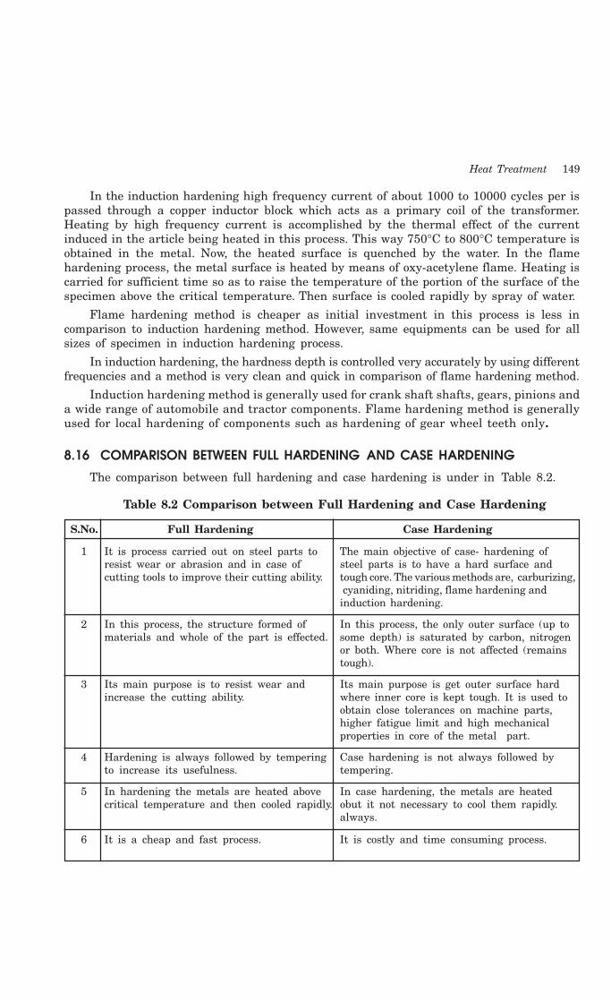
Heat Treatment 149
In the induction hardening high frequency current of about 1000 to 10000 cycles per ispassed through a copper inductor block which acts as a primary coil of the transformer.Heating by high frequency current is accomplished by the thermal effect of the currentinduced in the article being heated in this process. This way 750°C to 800°C temperature isobtained in the metal. Now, the heated surface is quenched by the water. In the flamehardening process, the metal surface is heated by means of oxy-acetylene flame. Heating iscarried for sufficient time so as to raise the temperature of the portion of the surface of thespecimen above the critical temperature. Then surface is cooled rapidly by spray of water.
Flame hardening method is cheaper as initial investment in this process is less incomparison to induction hardening method. However, same equipments can be used for allsizes of specimen in induction hardening process.
In induction hardening, the hardness depth is controlled very accurately by using differentfrequencies and a method is very clean and quick in comparison of flame hardening method.
Induction hardening method is generally used for crank shaft shafts, gears, pinions anda wide range of automobile and tractor components. Flame hardening method is generallyused for local hardening of components such as hardening of gear wheel teeth only.
8.16 COMPARISON BETWEEN FULL HARDENING AND CASE HARDENING
The comparison between full hardening and case hardening is under in Table 8.2.
Table 8.2 Comparison between Full Hardening and Case Hardening
S.No. Full Hardening Case Hardening
1 It is process carried out on steel parts to The main objective of case- hardening ofresist wear or abrasion and in case of steel parts is to have a hard surface andcutting tools to improve their cutting ability. tough core. The various methods are, carburizing,
cyaniding, nitriding, flame hardening andinduction hardening.
2 In this process, the structure formed of In this process, the only outer surface (up tomaterials and whole of the part is effected. some depth) is saturated by carbon, nitrogen
or both. Where core is not affected (remainstough).
3 Its main purpose is to resist wear and Its main purpose is get outer surface hardincrease the cutting ability. where inner core is kept tough. It is used to
obtain close tolerances on machine parts,higher fatigue limit and high mechanicalproperties in core of the metal part.
4 Hardening is always followed by tempering Case hardening is not always followed byto increase its usefulness. tempering.
5 In hardening the metals are heated above In case hardening, the metals are heatedcritical temperature and then cooled rapidly. obut it not necessary to cool them rapidly.
always.
6 It is a cheap and fast process. It is costly and time consuming process.

150 Introduction to Basic Manufacturing Processes and Workshop Technology
8.17 HEAT TREATMENT OF TOOL STEEL
First of a1l, the purpose or functional requirements of the tool to be used should be understoodclearly. Accordingly the heat-treatment will be carried on the tool to obtain the desiredqua1ities in the tool steel to meet the needed objective. For example a cutting tool requiresparticularly sufficient strength, high hardness and high wear-resistance. Therefore, it isinitially shaped by forging operation which should be carried out at temperature 850°- 950°Cwith the help of hammers. Next normalizing is to be performed on it to relieve the stressesand strains developed during forging and to have a uniform grain structure. Next the toolsteel is hardened by heating followed by sudden or rapid cooling depending upon the carbonpercentage in tool steel. The various heating ranges of different tool steels are as follows
C% in tool steel Heating Range
0.7- 0.8% 780-850°C
0.8- 0.95% 765-790°C
0.95-1.10% 750-775°C
Above 1.10 % 740-760°C
The tool steel is heated to this temperature range and kept at that temperature forsufficient time to achieve uniform structure inside the metal. Then it is quenched by immersingit into a bath of fresh water (rapid cooling). For securing more homogenous cooling andreduce danger of cracking, brine solution (10% brine or caustic soda solution) may be used.After hardening, tempering is performed to remove extra hardness and brittleness inducedduring hardening. This is performed by reheating the hardened tool steel up to 150-300°Conce again and same is cooled in oils to reduced internal stresses. Tempering is carried overto tool steel for the purpose of increasing its usefulness and to provide good results in itsperformance. The important point is to note that drills and milling cutters should be hardenedthrough out. But certain tools like screw taps, screw dies, lathe, planer and shaping tools arenot hardened throughout the surface of the cutting tools.
8.18 HEAT TREATMENT OF HIGH SPEED STEEL
First the HSS tool is heated to about 850°C and kept at this temperature for 4 to 5 hours.This is done to dissolve all the carbides or homogenization of WC, VC and Cr4C3. After it, toolis heated to 1200°C for 1-4 minutes. The purpose of heating to high temperature is that morethe substance is cooled from high temperature to lower temperature difference, the more willbe the hardness. Tool is not kept at such temperature for sufficient longer time. After this,it is quenched in salt bath to 650°C and kept at this temperature for 10-20 minutes. Directquenching to room temperature is dangerous. Then the tool is oil quenched. For increasingthe life of HSS tool, surface treatment processes are also done like, liquid cyaniding, gascyaniding and solid or dry cyaniding.
8.19 QUESTIONS1. Why are the Time-Temperature-Transformation (TTT) diagrams constructed?
2. How do you classify the different heat treatment processes?
3. What are the objectives of annealing?
4. Explain the various methods of annealing?
5. Explain various hardening methods?
Heat Treatment 151
6. Write short notes on :
(a) Normalizing
(b) Tempering
(c) Mar-tempering
(d) Aus-tempering
(e) Case hardening
(f) Flame hardening
7. Discuss tempering process in detail?
8. Discuss various types of surface hardening or case hardening processes?
9. Explain the following case hardening processes:
(a) Cyaniding
(b) Nitriding
(c) Induction Hardening
(d) Types of carburizing
10. Write short notes on :
(a) Sub zero treatment of steels
(b) Age Hardening.
11. Explain various heat treatment defects with causes and remedies.
152 Introduction to Basic Manufacturing Processes and Workshop Technology
152
CARPENTRY
9.1 INTRODUCTION
Wood obtained from tree is the chief product of forest. It has been universally acceptable asraw material for manufacturing wooden products or appliances. From the pre-historic times,wood has been utilized an important source of getting heat by firing it. It has been utilizedas an mazor construction material for making shelter for the basic need of human being. Asthe civilization advanced, it gained tremendous importance as special material for boat-building, for piling to support docks and railroad tracks. But in modern times, with theadvance of wood chemistry, the uses of wood have recognized its importance in manufacturingcheap useful products used in day today life such as paper, furniture, textiles, plastics andhundreds of chemicals and extractives. The wooden products as plywood have superseded insome products in comparison metallic and ceramic materials. Compressed wood has alsoreplaced some metals for gears and die casts. In war-time, in Europe, wood has been usedas a source of wood gas for propelling automobiles. Similarly clothing has-been made fromwood cotton and wood wool. The useful work on wood is being generally carried out in a mostcommon shop known as carpentry shop. The work performed in carpentry shops comprisesof cutting, shaping and fastening wood and other materials together to produce the productsof woods. Therefore, carpentry shop deals with the timber, various types of tools and the artof joinery. In wood, there are two types of cells namely radiating outward from the centerof wood cross-section and running parallel to the length of wood. Trees are generally classifiedinto exogenous and endogenous types according to manner of growth.
Exogenous types are also known as outward growing trees which produce timber forcommercial use. They grow outward and the additional growth which occurs each year takesplace on the outside of the trunk just underneath its bark, while the innermost timbercontinues to mature. Each time the growth cycle is completed the tree gains one more growthring or annual ring. In counting these rings, the age of a tree can be determined, as eachring represents one year of growth.
Endogenous trees are also known as inward growing. They grow inwards i.e., every freshlayer of sapwood is added inside instead of outside. Cane, bamboo and coconut are examplesof such endogenous trees.
Timber is a common name imparted to wood suitable for engineering, construction andbuilding purposes. Timber is obtained from trees by cutting the main body of tree in thesuitable sizes after the full growth of tree. The timber structure is consisting of annual rings,
9CHAPTER

Carpentry 153
heartwood, sapwood, pith, cambium layer, bast, medullary rays and bark. Commercial timbersare commonly classified into hardwoods and softwoods. Hardwoods comprises of oak andbeech that have a broad leaf. Whereas softwoods include pine and spruce which have narrowneedle like leaf.
This chapter presents the various kinds of material, tools and equipments used in carpentryshop along with their properties and uses.
9.2 HARD AND SOFT WOOD
Hard wood is generally obtained from broad leaves or deciduous trees where as the softwoodfrom trees having needle shaped yes or conifers. The major differences between hard woodand soft wood are given as under.
Table 9.1 Difference between Hard Wood and Soft Wood
S.No. Hard Wood Soft Wood
1 It is dark in color Its color is light
2 It is heavy in weight. It is light in weight
3 Hard woods are harder and denser. Soft woods are comparatively lighter
4 It has less resin content Few softwoods are resinous.
5 It does not split quickly It gets splitted quickly
6 It is difficult to work. It is easy to work.
7 It’s annual rings are close and often Its annual rings are well spaced and quitindistinct distinct
8 It is slow growing. It is fast growing.
9 It has good tensile and shear resistance. It has good tensile resistance but is weakacross the fibers.
10 It does not catch fire very soon It catches fire very soon.
9.3 TYPES OF COMMON TIMBERS, THEIR QUALITIES AND USESThe common types of well recognized timbers available in India are Shisham, Sal, Teak,Deodar, Mango, Mahogany, Kail, Chid, Babul, Fir wood, Walnut and Haldu,. Out of these,Deodar, Chid, Kail, Fir wood and Haldu fall in the categories of softwoods and Shisham, Sal,Teak, Kiker, Mango, Walnut fall in the categories of hardwoods. Some of the other foreigntimbers commonly used in India are Ash, Burma, Hickory, Oak and Pine.
1 Shisham is dark brown in color and it possesses golden and dark brow stripes. Itis very hard to work and generally wears or blunts the sharp edge of cutting toolvery soon. It is available in India in Himalayan range at heights from 1000-1500meters and in deep forests. It is recognized as highly strong and durable wood andit is mainly used for making good variety of furniture, tool handles, beds, cabinets,bridge piles, plywood etc.
2 Sal exists in rose brown color which slowly turns into dark brown. This wood iscommonly available in India in Himalayas, M.P and U.P. It is free from attack ofwhite ants insects and it is very difficult to work. It has poor finish and therefore
154 Introduction to Basic Manufacturing Processes and Workshop Technology
is not used for decorative furniture. It finds tremendous applications in makingdoors, windows, cots, wooden handles, furniture and railway sleepers etc.
3 Teak wood is hard, very costly and it possesses wide applications. It is availablein golden yellow or dark brown color. Special stripes on it add to its beauty. In India,it is found in M.P. It is very strong, durable and it maintains good polish. It ismainly used for making good quality furniture, plywood, ships etc.
4 Deodar is white in color when soft. But when it is hard, its color turns toward lightyellow. It is strong and durable. It provides fragrance when smelled. It is not easilyattacked by insects as it has some quantity of oil in it. It is commonly available inHimalayas at a height from 1500 to 3000 meters. It is used for manufacturing ofdoors, furniture, patterns, railway sleepers etc.
5 Mango is brown in color and it can be easily shaped in various products. It is widelyused in India as a cheap wood for making doors, packing cases, toys and inferiorfurniture.
6 Mahogany is reddish brown in color which is highly durable when dry. It alsocontains some oil in it that prevents it from the attack of insects. It is commonlyutilized for manufacturing cabinet, fine furniture, pattern making work etc.
7 Kail wood possesses too many knots in it. This wood is commonly found in Himalayasof India. It yields a close grained, moderately hard and durable wood which can beeasily painted. It is commonly utilized for making cheap furniture, wooden doors,packing case etc.
8 Chid is also known as Chir. Its color is dark brown when is soft, but it is reddishbrown when hard. It has stripes of dark brown color. It has oily smell and is usedfor interior work in the house.
9 Babul is close grained tough and pale red colored wood and is used for making toolhandles etc.
10 Fir wood is light brown in color when soft but harder variety is found in darkbrown color. It can be easily attacked by insects. It is commonly utilized for makingdrawers, packing cases, doors etc.
11 Walnut is a good variety of wood which resists the attack of white ants. It can bepolished easily in a better way. This wood is generally used for making musicalinstruments, furniture, cabinet work, decoration work etc.
12 Haldu is white in color at the time of cutting, but once cut, its color becomesyellow. It can be dried and polished satisfactorily. It is widely used for making smallobjects such as stool, picture frames, trays, cabinet etc.
9.4 FELLING, CONVERSION AND SEASONING OF WOOD
Cutting of living or standing trees to obtain timber is called felling of trees. Trees are cut atappropriate time. The best time for sawing the tree is immediately after the tree has achievedits full growth or maturity age so that the maximum quantity and best quality of wood canbe obtained. If an immature tree is cut, it will carry a lot of sapwood which may not be muchuseful for the carpentry work. Contrary to this, if the tree is allowed to stand for long afterattaining the maturity the most valuable part of timber will be subjected to decay. Thereforeenough care must be taken to see that felling is accomplished only at the appropriate time.

Carpentry 155
The proper time of cutting of a tree depends largely on its age and season of the year. Cuttingof trees for getting wood for use is done generally in mid-summer or mid-winter because thesap of the tree is at rest during this period and therefore, the chances of any decay of usefulwood are minimized. The time taken for a tree to mature depends whether it is softwood orhardwood. The softwood tree will mature after 80 to 100 years whereas hardwood will takemore time between 130 and 200 years for getting mature. After cutting the trees from bottom,the branches are removed from it and form of log is obtained. The process of sawing woodenlogs into useful sizes and shapes (boards, planks squares and other planes section and sizesetc.) for market or commercial requirements is known as conversion. Conversion is carriedover prior to seasoning by two methods namely plain, through, through sawn process andquarter and rift sawn process. Plain sections of wood may likely to warp and hence cannotbe used for quality work. Quarter sawing almost eliminates the chances of warping. Quartersawn sections are used as quality wood in cabinet making, decoration and framework. Plantationof new trees is also essential and that should be carried out form time to time.
Conversion means sawing of timber logs into different commercial sizes. A notable featurein conversion is to provide an adequate allowance for shrinkage that takes place duringseasoning of sawn or converted wood. The shrinkage of wood usually varies between 3.2 mmto 6.4 mm, according to the type of wood and its time of cutting. The three methods ofconversion commonly adopted are discussed as under.
The first method is called as flat or ordinary cutting which is the simplest procedure ofsawing but the cut sections are likely to warp. Therefore, the wood cut through this procedurecannot be called as quality work. In this method, the timber log is cut into a number of boardsby taking various parallel saw cuts into the suitable forms.
The second method is known as tangential cutting in which cutting takes place in sucha way that the widths of the boards are tangential to the annual rings. The timber cut bythis method is seasoned quickly and cutting wastage is also less but it may warp like flat sawnwood.
The third procedure is known as quarter or radial sawing in which the timber logs aresawn so that the width of the sawn boards falls along the medulary rays which mean theyrun across the section of the log. The normal defect of warping is almost eliminated by thisprocedure of sawing and the timber is very suitable for all sorts of wood work involvingcabinet-making, decoration and framework. Trees are converted into the following usefulmarketable forms such as posts (square pieces of timber 175-300 mm wide or round piecesof 175-300 mm in diameter), deals (225 mm wide and about 100 mm thick parallel side pieces),planks (50 to 100 mm thick, 275-300 mm wide and 3 to 7 meters long) and boards or battens(25 to 50 mm thick and 125 to 175 mm wide). Sizes of timber (Kail, Deodar etc.) available inthe market for building construction purposes are 10' × 10" × 5" or 12' × 10" × 5" or 10' ×8" × 5" or 10' × 8" × 4" etc.
Seasoning of wood is the reduction of the moisture or sap content of it to the pointwhere, under normal conditions of use, no further drying out will take place. The mainobjective of seasoning is to reduce the unwanted amount of moisture from the timber. As themoisture contained in the cell walls evaporates, shrinkage of the timber takes place whichis greatest along the growth rings. Certain other defects such as shaking and warping maydevelop during seasoning. Therefore for these reasons green or unseasoned timber should notused for any work but for rough work. Once the timber is seasoned before use, it will notshrink, twist or swell during its further use. Need for seasoning of timber before its use is
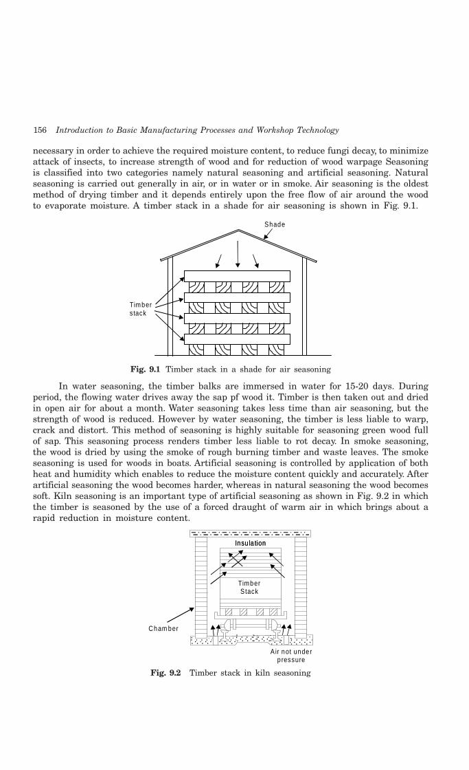
156 Introduction to Basic Manufacturing Processes and Workshop Technology
necessary in order to achieve the required moisture content, to reduce fungi decay, to minimizeattack of insects, to increase strength of wood and for reduction of wood warpage Seasoningis classified into two categories namely natural seasoning and artificial seasoning. Naturalseasoning is carried out generally in air, or in water or in smoke. Air seasoning is the oldestmethod of drying timber and it depends entirely upon the free flow of air around the woodto evaporate moisture. A timber stack in a shade for air seasoning is shown in Fig. 9.1.
Shade
Timberstack
Fig. 9.1 Timber stack in a shade for air seasoning
In water seasoning, the timber balks are immersed in water for 15-20 days. Duringperiod, the flowing water drives away the sap pf wood it. Timber is then taken out and driedin open air for about a month. Water seasoning takes less time than air seasoning, but thestrength of wood is reduced. However by water seasoning, the timber is less liable to warp,crack and distort. This method of seasoning is highly suitable for seasoning green wood fullof sap. This seasoning process renders timber less liable to rot decay. In smoke seasoning,the wood is dried by using the smoke of rough burning timber and waste leaves. The smokeseasoning is used for woods in boats. Artificial seasoning is controlled by application of bothheat and humidity which enables to reduce the moisture content quickly and accurately. Afterartificial seasoning the wood becomes harder, whereas in natural seasoning the wood becomessoft. Kiln seasoning is an important type of artificial seasoning as shown in Fig. 9.2 in whichthe timber is seasoned by the use of a forced draught of warm air in which brings about arapid reduction in moisture content.
Insu la tionInsu la tion
TimberStack
Air not underpressure
Cham ber
Fig. 9.2 Timber stack in kiln seasoning

Carpentry 157
9.5 DEFECTS IN TIMBER
Defects in timber may be broadly classified into three major categories
1 Due to abnormal growth of trees
2 Due to conversion or seasoning and
3 Due to fungi and insects.
The defects in each category are described as under.
9.5.1 Defects Due to Abnormal Growth of TreesDefects due to abnormal growth of trees are natural in nature and they are knots, stakes,twisted fiber and rind galls.
Knots are too much frequent in many trees. They break the continuity of fiber andweaken the timber. These defects may of dead or live kind. Fig. 9.3 shows a knot defect. Adead knot will come out of the wooden piece leaving a knot hole. It is produced when a branchis broken off before the tree has finished growing. A live knot occurs when a branch separatesfrom the tree after felling of the tree. Live knot will not become loose and fall out of itsposition but may tend to crack. This provides inlets for any fungi to attack the wood. If theseknots are not too large and not too near the edge of the plank, they will not present a greatproblem however dead knots in timber makes the wood unsuitable for structural use.
Knot
Fig. 9.3 Knot defect in timber
Shakes in timber are splits in the grain and often arise as a result of uneven seasoning.They may be of radial, heart, star, cup and upset kind. An upset or rupture is a shake inwhich the fracture occurs across the grain. This is thought to be caused by violet jarring ofthe timber during felling and is often found in mahogany.
Sometimes, the fibers of a tree may get twisted due to wind action in branches. Thisdefect is known as twisted fibers defect in timber. The fibers of wood have different inclinationswith its axis. They are no more parallel to the axis of the wood. Twisted fibers in timber offerdifficulty in working and a smooth surface cannot be obtained.
Rind gall is the defects due to abnormal growth of trees. It is the wound created onthe tree while a branch breaks and parts off or gets cut. Decay may occur at that point.
9.5.2 Defects Due to Conversion and SeasoningDefects due to conversion and seasoning of timber involve shakes, warping, bowing, twist, diamonding,casehardening and honey combing. Some of such important defects are discussed as under.
Warping is a kind of variation from a true or plain surface and may include a one orcombination of cup, bow, crook and twist. Warping board which is tangentially sawn mayinvariably warp. This takes the form of a hollowing or cupping across the face of the boardand when wide flat boards are required this will act as a serious drawback. Wind or twistdefect occurs when thin boards are cut from a log having curved longitudinal grain. Thistendency is for the board distort spirally.
158 Introduction to Basic Manufacturing Processes and Workshop Technology
Diamonding in timber is the tendency of square cut pieces to become diamond shapedwhen cut from certain areas of the log. This happens when the piece has been cut withgrowth rings running diagonally, causing the unequal shrinkage between summer and springgrowth to pull it out of shape.
9.5.3 Defects due to Fungi and InsectsDefects due to fungi and insects in timber involve fungi, dryrot, and wetrot which arediscussed as under.
Fungi in timber use the wood as their food and destroy the same. It acts on the woodtissues and cells and cause decay. There are two types of defects in wood because of fungi andinsects which are known as dry rot and wet rot.
Dry rot is a type of fungus on dry wood which feeds on damp wood and breaks it down.Dry rot is so called because infected wood eventually becomes lighter in weight and takes onthe appearance of being badly charred by fire, except that it is brown in color instead of blackand crumbles under slight pressure. This fungus cannot develop in wood which has a sapcontent of less than 20% so that to prevent it, all that is really necessary is to use seasonedtimber and to keep it dry.
Wet rot in timber is the decay due to dampness. The wood looks wet due to fungi attackon living trees. The effected positions of wood are reduced to a gray brown powder. Wellseasoned wood, protected by painting etc., will avoid wet rot.
Insects such as beetles, borers and white ant attack the wood and render it of no use.Beetles are commonly found in temperate region and the field of tropical and non tropicalregions. Beetles use timber as their food. Borers produce holes in the timber to find shelterfor living. White ants or termites are very common in warm temperature countries. Theyattack the wood, and make it hollow from inside. The insect attack may be controlled throughthe use of insecticides. In another method, the timbers are placed in a kiln where steam andheat are used to suffocate the pests.
9.6 TIMBER PRESERVATION
It is highly essential to protect timber from attack of fungus and any damage from insectattack. Timber products require protection if it is exposed to weather such as doors, windows,poles etc. Extending the life of the timber through preservation is a much cheaper deal. Theobject of treating timber with a preservative is to render it immune to decay, even thoughit may become quite damp and to prevent attack by timber boring insects. Most timberpreservatives belong to one of three main group tar-oil derivatives creosote, water solubletype and organic solvent chemicals.
9.7 CHARACTERISTICS OF A GOOD TIMBER
Timber is free from knots, insects attack, excessive moisture, discoloration, twisted fibers,cup and ring shake, sound, bright and free from any discoloration. It is solid with annual ringsbut not hallow in the center. Timber should be well seasoned for easily workable specific use.It should possess straight fibers and high fire resistance. It should not split when nails aredriven in it. It should not clog with the saw teeth during the sawing operation. Timber shouldbe highly suitable for polishing and painting.

Carpentry 159
9.8 FACTORS INFLUENCING TIMBER SELECTION
The factors influencing the selection of timber involve the quality of timber in terms of itsdurability, workability, weight, hardness, cohesiveness, elasticity, type of texture, type ofgrains, resistance to fire, resistance to various stresses, ability to retain shape, suitability forpolishing and painting.
9.9 PLYWOOD AND APPLICATIONS
For the last so many years, the use of the plywood and other manufactured boards has, invarying degrees have replaced the use of solid timber in the making of furniture, fittings,paneling and many forms of constructional work. Plywood is generally made of three or moresheets of veneer glued together, with the grain of successive plys laid cross-wise. Since thestrength of timber lies along the grain, when plys of veneer are bonded in opposing graindirection, strength is distributed to both length and breadth of the piece. The plywood can beobtained in much larger sizes without shrinkage and warping in comparison to plain wood.The molded plywood boats, television and radio cabinets can be formed from plywood. Theplywood can withstand easily against humid condition. Plywood is lighter in weight andstronger across the grain than even the toughest hardwoods. Screws and nails can be drivenclose to the edge of plywood without any danger of splitting. High class surface finish can beare easily obtained on plywood.
The development of moisture and heat-resistant adhesives have contributed to the useof laminated members for heavy truss construction, to the gluing together of narrow boardsto make wider ones, and to the making of finger joints by which short lengths are joined tomake longer pieces. Plywood is used for many forms of construction, including sheathing,interior finish, sub flooring, under-roofing, paneling, flooring, cabinets, furniture, shelving,partitions, ceilings, containers such as baskets, boxes, crates, trunks into boats, toys, tables,woodenware and repair work in garages and basements.
9.10. MISCELLANEOUS MATERIAL USED IN CARPENTRY SHOP
There are a number of other materials used in carpentry shop besides timber. The mainmaterials are dowels, nails, screws, adhesives, paints and varnishes. A brief description ofsuch material is given as under.
Dowels
Dowels are wooden pieces of special nails kind generally made out from bamboos orother similar wood by the carpenter himself. They are used for fastening different woodstructural components. Hole is initially drilled through the two pieces or parts to be joinedtogether. After assembling of in proper position of the parts to be joined, the dowel is thendriven through the parts.
Nails
Nails in wood work are made out of drawn wire of brass or copper or low carbon steelor malleable iron rods. Nails made from drawn wires are termed as wire nails and areproduced from rods as clasp nails. The clasp nails possess a better holding capacity than wirenails. According to the use, the wire nails are subjected to light and medium work while theclasp nails are commonly used for heavy work. Nails are mainly used for reinforcing glued
160 Introduction to Basic Manufacturing Processes and Workshop Technology
joints and fastening different component of woods. Their size is specified by length anddiameter. These are sold by weight in the market.
Screws
Screws are made from bright drawn wires or thin rods and they are used mainly forfixing the metallic fittings like hinges and hasps in wooden structure.
Adhesives
Adhesives is defined as the sticking substance such as glue, paste, cement and mucilagethat is capable of holding wooden parts together by surface attachment permanently. It iscommonly used to join together the boards edge-to edge to form a larger surface or face-to-face to increase the thickness. It is applied on large surface areas of material as when layingveneers and is also used to stick together relatively small surface areas such as wood workingjoints. An efficient adhesive or sticking paste or glue is one that maintains good bond betweenthe wooden elements under the conditions of service that the joint has to withstand. It isrequired frequently for joining together the wooden boards edge to edge to form a largersurface or face to face to increase thickness in joinery work and many other common typesof wood works. It is applied either cold or hot condition. The former is known as liquid orcold glue and is used when a slow and less strong setting is desired. When applied hot, it isknown as cooked glue that enables a very strong and permanent type of joint between theadjacent layers of wood pieces. Few commercially available adhesives can be classified ascasein glue, animal glue, vegetable glue, albumen glue, synthetic resins, poly-vinyl-acetate(PVA), paint and varnishes, rubber cement and plastic cement and few important such adhesivesare briefly discussed as under.
Casein glue
Casein glue is made by adding an alkali to the curd of skimmed milk. It is commerciallyavailable in powdered form in the market. It can be made into a paste, while using, by addingwater. It is thicker than animal glue but squeezes out of the joint quickly when pressed. Thisglue requires 15 to 20 minutes to set a wooden joint and therefore thus provides the carpentersufficient time to glue and clamp his work. Casein glue is a commonly used adhesive whichis very strong and water resistant. It is used specially in components which are continuouslysubjected to high humidity viz. furniture, boat making, veneering, beams and others woodencomponents.
Animal glue
This glue is made from hides, hoofs, bones and other waste parts of animals. Thesematerials are refined and developed in form of sheets, flakes or powder. Before applying, theglue should be soaked in cold water over night and then heated. It is generally applied hotand sets very rapidly. It is also available in liquid form commercially which is applied cold i.e.it does not require any heating before application. An important point is to be noted that thisglue should be applied immediately after heating. Repeated heatings should be avoided as thisweakens the bond of the glue and also its fluidity is lost due to evaporation of water,rendering it thicker.
Vegetable glue
It is developed from the starch which is obtained from roots, grains and corns of treesby subjecting them with acid and by grinding to a powered form. It is mainly used in plywoodwork and it is not much suitable for general work

Carpentry 161
Albumen glue
It is prepared by adding an alkali to beef blood and is available in flakes forms in themarket. During use they are dissolved in water in about an hour earlier, to found a liquidsolution and it gives a very strong and water proof bond.
Synthetic resin glue
This glue is made from formaldehyde uric acid and other chemicals. It is available ingenerally powder form. Before use, it is thoroughly mixed with water to proper consistency.The commercial varieties of resin glue involve polyvinyl-resin glue in liquid form, plastic resinglue in powder form and resorcinol-resin. The polyvinyl glue is the fastest setting, strong,easy to use and it is extensively used in furniture and decorative work. The plastic resin glueis mainly used in plywood work. The resorcinol glue can be used for joining wooden partswhich are constantly subjected to changing weather condition exposed to humid environment.
Paint and varnishes
They are commonly applied on wooden or metallic articles for the reasons to protectingthe surfaces of wood or metal from the effects of moisture and weather change. They are usedon surfaces for making them decorative in appearance.
9.11 CONSTITUENTS OF AN OIL PAINT
A good paint must have sufficient fluidity so that it can be easily spread by a brush over thesurface. It should form a durable and wear-resistant film on drying over the surface of wood.It should retain its color on drying and under changing conditions of atmosphere and shouldnot be affected much by moisture. It should give a pleasing appearance to the surface ondrying. An oil paint comprises of various constituents such as base, vehicle, pigments, thinnerand driver which are discussed as under.
Base is a major constituent of oil paint. It is finely ground powdered material which ismixed and then applied to the surface of the finished part to form the body of the paint. Thefunctions of a paint base is to provide a sort of reinforcement to the film coated on the surfaceof finished parts after it dries, in order to make it hard and wear-resistant for long life. Italso minimizes the chances of cracking of the coated film of paint after drying. Commonlyused bases involve white lead, red lead and iron oxide.
The second constituent named as vehicle will act as a binder for the solid material andenables suspension of base and other coloring pigments in order to allow their even applicationon the prepared surface of the products and it facilitate its adherence to the latter. The wellknown vehicles are raw linseed oil, single or double boiled linseed oil, refined linseed oil, nutoil, stand oil and poppy oil.
The third constituent of oil paint function is pigments which provide various colors tothe paints. They are generally available in fine powdered form and the best one is which doesnot change its color even on being exposed to sun and heat. The black color oriented commonpigments are graphite, lamp black, and vegetable black. The blue color oriented commonpigments involve Prussian blue, cobalt blue, indigo. The green color oriented common pigmentsis chrome green. The red color oriented common pigments are Indian red, red lead, vermilion,and venetian red. The brown color oriented common pigments are raw umber, burnt umber,raw sienna, burnt sienna. The black color oriented common pigments are chrome yellow andyellow achre.

162 Introduction to Basic Manufacturing Processes and Workshop Technology
The Thinner is a such a solvent which, when added to the paint, reduces its consistencyand, thus, enhances its flow ability thereby facilitating an easy and quick spreading of paintover the surface of the job in the from of an uniform thin film. It is important to note thatthe thinner should not be added to the paint in an excessive quantity. The amount of athinner in paint varies between 5 to 8 percent of the paint. The commonly used thinners areturpentine and naphtha.
The main objective or function of a drier in oil paint is to increase the rate of dryingof the vehicles and hence the applied paints. The generally used driers are red lead, zincsulphate, lead acetate, lead oxide and manganese sulphate.
9.12 COMMON TOOLS USED IN CARPENTARY SHOP
Commonly used tools to shape wood for various types of joints by driving in and driving outnail involve cutting and smoothening of wood surfaces. A broad classification of tools used inthe wood working or carpentry shop are measuring and marking tools, supporting and holdingtools, cutting tools, striking tools and miscellaneous tools. Most of commonly used tool andmeasuring devices as mentioned above are in chapter of fitting and sheet metal work also.Other some important such tools and instruments are discussed as under.
9.12.1 Marking and Measuring ToolsMarking in order to make wooden components of the required size or the marking of exactdimensions on the wooden piece is essential to produce quality jobs. A number of markingand measuring instruments namely Rules, Try Square, Combination Set, Bevel Gauge, MarkingGauge, Mortise Gauge, Cutting Gauge, Spirit Level, Trammel and Compass are commonlyused for this purpose. Some of commonly used marking and measuring instruments arediscussed as in chapter of fitting and sheet metal work under.
Rules
Rules are straight edge of wood or steel engraved in millimeters- centimeters or ininches-foot or in both. Theses are used to mark, measure the length, widths and thicknessesof wood part. Figs. 9.4.-9.6 show steel rule, folding rule and flexible steel rule. These rulesare available in different sizes and designs. Metallic taps bearing sizes 6", 12" or 18" are usedfor general measuring work. For example 24" folding tape and 5" or 6" steel tape are usedmeasuring larger dimensions. An important small instrument in any shop is a good qualitystraight-edge bench rules. These rules are manufactured of either metal or wood. They areused to check for straightness and to measure and mark straight lines. The bench rule maybe graduated in inches, millimeters or both. The length of the bench rule may be 12", 24"or 36". The 36" rule is called yardstick. Another type of rule is folding two-foot rule which ismore convenient than a straight 24" rule. The zigzag rules are used to measure longer stockwhen exact measurements are not so important. One of These rules, when open may be ofusually 6 or 8 feet long. The push pull steel tape or tape rule is a very compact metal rulethat comes in lengths of 6, 8 or 10 feet. There is a hook at the end to slip over the edge ofthe bold. It is flexible to bends easily and can measure curved surfaces too. It is very goodfor measuring the inside depth of the hole of components also.
Try Square
Try square is generally utilized for measuring and checking of squareness, perpendicularity,dimensions, testing of finish of planned surfaces and drawing parallel and perpendicular lines.

Carpentry 163
The steel blade and metallic or wooden handle of try square are at right angles to each other.Try square is used for testing the level, edge and square ness of the wooden surfaces. It isalso used for marking lines across the face or edge of wooden block. There are graduationsalong the blade of the rule that are used for measuring and marking purposes on the woodenjobs. The blade of try square is made of hard tempered steel of non rusting kind. It is seldomused for hammering work.
1 2 3 4 5 6
Fig. 9.4 Steel rule
31 32 33 34 35 36 37 38 39 40
1718192021222324252627282930
Fig. 9.5 Folding rule
1 2 3 4 5 6
Scale
Fig. 9.6 Flexible steel rule
Combination Set
Combination set is frequently used in the carpentry shop for different kind ofmeasurements. It consists of blade and a head. The blade has a groove cut along its lengthso that it can slide into the head. One side of the head makes a 90° angle with the blade andthe other side a 45° angle. It can be making, measuring and setting different angle. It alsoacts as a try square, angle gauge to set 45° angles, a depth gauge and level checking tool.
Bevel Gauge
Bevel gauge is also known as an adjustable bevel which is mainly used for marking,measuring and inspecting angles from 0 to 180 degree. Its blade can be adjusted and set toany desired angle.
Marking Gauge
The marking gauge is made of wood which is important tool utilized to make lines ata uniform distance from the edge of a board or piece of work and is used principally whenpreparing wooden components to size before jointing. The marking gauge like the mortisegauge and cutting gauge in use should be positioned correctly. For marking purposes, thegauge is drawn towards the body or pushed away from it but in either case, if the spur doesnot trail. It will tend to jump and run with the grain. Thumb screw of the marking gaugelocks the stock at any position. The spur made of hardened steel should be ground to a finepoint. And for ease of working, it should not project too far from the face of the stem. It is

164 Introduction to Basic Manufacturing Processes and Workshop Technology
commonly used to mark or scribe line parallel to and at any desired distance from a finishededge or face of a surface
Cutting Gauge
Cutting gauge is similar in construction to the marking gauge but having a knife in placeof the marking pin or spur. It can be utilized for gauging and marking deep lines across thegrain of wood in thicker sections. It is also used for setting out the shoulder-lines of lapdovetails and similar joints, as well as for trimming veneers parallel to the edge of surfacebefore laying a cross-band. Cross banding is the laying of a strip of cross-grained veneeraround the edge of a surface for example the edges of a table top, box lid or drawer front.This gauge is very useful for making very small rebates to receive inlay lines and may beused in place of marking gauge. Inlay lines are thin strips of wood which can be glued intoa rebate cut around the edge of a veneered surface.
Mortise Gauge
9.7 shows a mortise gauge. This is an improved form of marking gauge which consistsof main components as fixed pin, sliding pin, brass strip, stem, rose wood stock and thumbscrew. The fixed pin of the gauge is attached to a short brass strip which is screwed to thestem. The sliding pin is fixed to a long brass strip or slider is adjusted by means of athumbscrew. The threaded portion of which engages in a cylindrical nut which is embeddedin the stem. The stock is locked in position by a metal set screw. This gauge is used formarking out of the parallel sides of a mortises or tenons and other similar joints.
FixedPin
Slid ingPin Stock G roove
Screw
Fig. 9.7 Mortise gauge
9.12.2 Holding And Supporting ToolsSometimes it is desirable to support and gold a wooden board in a special manner while thework is being carried out. For these purposes, various supporting and holding devices areneeded some of which are discussed as under.
Work Bench
Every carpenter generally needs a good solid bench or table of rigid construction of hardwood on which he can perform or carry out the carpentry operations. Work bench should beequipped with a vice for holding the work and with slots and holes for keeping the commonhand tools. One jaw of the vice is tightened to the table and is kept moveable for holding thearticles Work benches are built solidly with good heavy tops for providing a good workingsurface for cutting, as well. The vice on the bench is equipped with an adjustable dog thatis, a piece of wood or metal can be moved up and down in the outside jaw of the vice.
Carpenter Vice
Carpenter vice (Fig. 9.8) is very important tool in wood working shops for holdingwooden jobs. There are several varieties of vices, each possessing its own particular merit.

Carpentry 165
Jaw
Trigger for qu ick opening
Fig. 9.8 Carpenter vice
Clamp
Clamps are commonly used in pairs in gluing up operations at the final assembly of woodjoinery work. These clamps can provide pressure required to hold joints together until theyare secured due to the setting of glues. Clamps are of two types namely plain rectangular bartype and T-bar type. The former is made of mild steel and is usually rectangular in section.The later may be of T-section, which can easily afford greater rigidity under stress. Thecoarse adjustment jaw may be located in any position on the bar by means of a steel pin whichfits into any of the holes drilled at intervals along the bar. The fine adjustment jaw of thesash clamp is moved along the bar by a square threads screw which passes through a specialnut fixed to the end of bar. Considerable pressure can be applied by turning the screw withthe Tommy bar for holding a wooden job. Both jaws of the sash clamp are generally madeof malleable cast iron which is tougher and less brittle than ordinary cast iron. There areother similar types of such clamps named as rack clamp, screw clamps, light duty parallelclamp, adjustable bar clamp (Fig. 9.9), G or C-clamp (Fig. 9.10), and double bar clamp whichare useful for holding different sizes and shapes of wooden jobs.
Hand lePin
Ho le T-bar
JawsHeadScrew
Base
JawsScrew
W ingnutBody
Job
Fig. 9.9 Bar clmap Fig. 9.10 G or C-clamp
9.12.3 Cutting ToolsVarious kinds of cutting tools namely various kinds of saws, planes, chisels, scraper, files, andrasp adze and axe and boring tools such as brace and bits, bradawl, auger, gimlet are usedin the carpentry shop. Few important types of cutting tools are described as under.
9.12.3.1 Saws
Saws are wood cutting tools having handle and a thin steel blade with small sharp teethalong the edge. They are utilized to cut wood to different sizes and shapes used for makingthe wooden joints that hold parts together. They can be further classified into three majortypes namely hand Saws (Rip, Cross-cut, Panel, Keyhole and, Pad saw), Snuff Saws (Tenon

166 Introduction to Basic Manufacturing Processes and Workshop Technology
and Dovetail) and Frame Saws (Coping, Bow and Fret). Few important types of saws areshown in Fig. 9.11. Some of them are described as under.
Rip Saw
The rip saw is shown in Fig. 9.11. It is used for cutting timber along the grains. The teethof rip saw are chisel-shaped and are set alternately to the right and left. A 24" long point sawis a good for sawing work. Depending upon whether the saw is designed to rip or cross-cut, theshape of the teeth will also vary. In the case of a ripsaw, the teeth are shaped like chisels.
Stee l b lade W oodenhandle
R ip S awR ip S aw Teeth
Cross cu t Handsaw
Cross cu t and panel teeth
Pane l Saw
Peg tee th fo r dovetailand tenon saws
Doveta il Saw
Tenon or back saw
Coping Saw
Compass saw
Bow saw
Fig. 9.11 Few important types of saws

Carpentry 167
Crosscut Saw
Cross cut saw is shown in Fig. 9.11 which is similar to rip saw in shape. It is primarilydesigned for cutting across the grains of wood. The teeth are knife shaped and bent alternatelyto the right and left for making the saw to cut wider than the blade. The saw cut is calledthe kerf. Since the kerf is wider than the blade, the blade will not stick as the sawing is done.The saw teeth may be coarse (with only 4 or 5 teeth per inch) or fine (with ten or twelveteeth per inch). A jaw for general purpose cutting should have about eight or nine points perinch (there is one more point than teeth per inch) and should be about 24 inches long.
Turning Saw
The turning saw is similar to the copying saw which is designed for cutting curves,scrolls and roundings on wooden jobs. It is used chiefly on heavier work where long faststroke and less accuracy of cutting are required. The thin blade of the turning saw isremovable. This saw can be pivoted between the handles. The saw generally cuts in thepulling stroke.
Dovetail Saw
Dovetail saw is shown in Fig. 9.11 which is little and is closely similar as related to thebacksaw or tennon saw. It is lighter and however possesses a thinner blade and finer teeth.The handle is round, to provide a delicate grip for fine cutting. This saw is used whereabsolutely finer and delicate cutting is required in wood work.
Compass Saw
Compass saw carries a tapered blade which is long as shown in Fig. 9.11 which is oneof the special saw having thin, narrow and flexible blade. With a blade resembling the beakof a swordfish, this type of saw is commonly used for making cutouts on the inside surfaceof a piece of work. A hole is first bored inside the portion which is to be cut out and thepointed compass saw is pushed into the hole to start the sawing operation. Its blade containsabout 12 teeth per cm length
Keyhole Saw
The keyhole saw is used in the same manner as the compass saw. For this reason it isgenerally employed for fine internal and intricate work where the compass saw would be toobig and clumsy for the carpentry job.
Hacksaw
Hacksaw is shown in Fig. 9.12 which consists of steel frame and a hacksaw blade. Whileessentially designed for cutting metal, this tool comes in for a variety of uses in the woodworking shop. The frame of hacksaw is designed in different ways, some with pistol grips,others with handles similar to those used on a conventional saw and others with turnedhandles. Blades of hacksaw are detachable and can be obtained with teeth of varying coarseness.
Hand le
Stee l fram e
LeverHSS B lade
W ing nut
Fig. 9.12 Hacksaw

168 Introduction to Basic Manufacturing Processes and Workshop Technology
9.12.3.2 Planes
A plane is a special tool with a cutting blade for smoothing and removing wood asshavings. It is just like a chisel fixed in a wooden or steel body. Fig. 9.13 shows a simpleplane. The modern plane has been developed from the chisel. They can also be classified asjack plane, smooth plane, jointer plane, trying plane, rabbit plane, circular plane and foreplane. Few important planes are discussed as under.
Bolt
W edgeThroatStrik ing
Bottom
Heel
Hand le
BladeM outhToe Block So le
Fig. 9.13 Simple plane
Jack Plane
Jack plane is most commonly used plane which is shown in Fig. 9.14 which comprisesof its body about 40 cm long, blade 5-6 cm wide and handle. It is good for rough surfaces thatrequire a heavier chip. It is ideal for obtaining a smooth and flat surface. There are actuallyforty-six different parts of jack plane, the carpenter needs only acquainted with the workingor regulating parts. The main working parts are the cutting blade or plane iron. The adjustingnut is operated to raise or lower the blade and the adjusting lever which regulates the bladeso as to make possible an even or slanted cut. The cutting blade of the jack plane is guardedwith a metal cap which is adjusted on top of the blade to within about 2.4 mm of the cuttingedge. The metal cap of the jack plane eases the cutting action by curling and breaking off thewood shavings evenly, thus preventing splitting or splintering of the wooden part.
Str ik ingButton
W edge Blade
Hand le
Fig. 9.14 Jack plane
Smoothing Plane
Smoothing plane is shown in Fig. 9.15 which is somewhatsmaller than the jack plane, measuring between 6 and 10 inchesin length. It is a fine utility tool, especially useful for planning endgrain, chamfering, and other edge shaping of wooden part. Thisplane is also used for cleaning up after gluing and assembly, butowing to its short length should not be used for producing verytrue surfaces.
Blade
Fig. 9.15 Smoothing plane
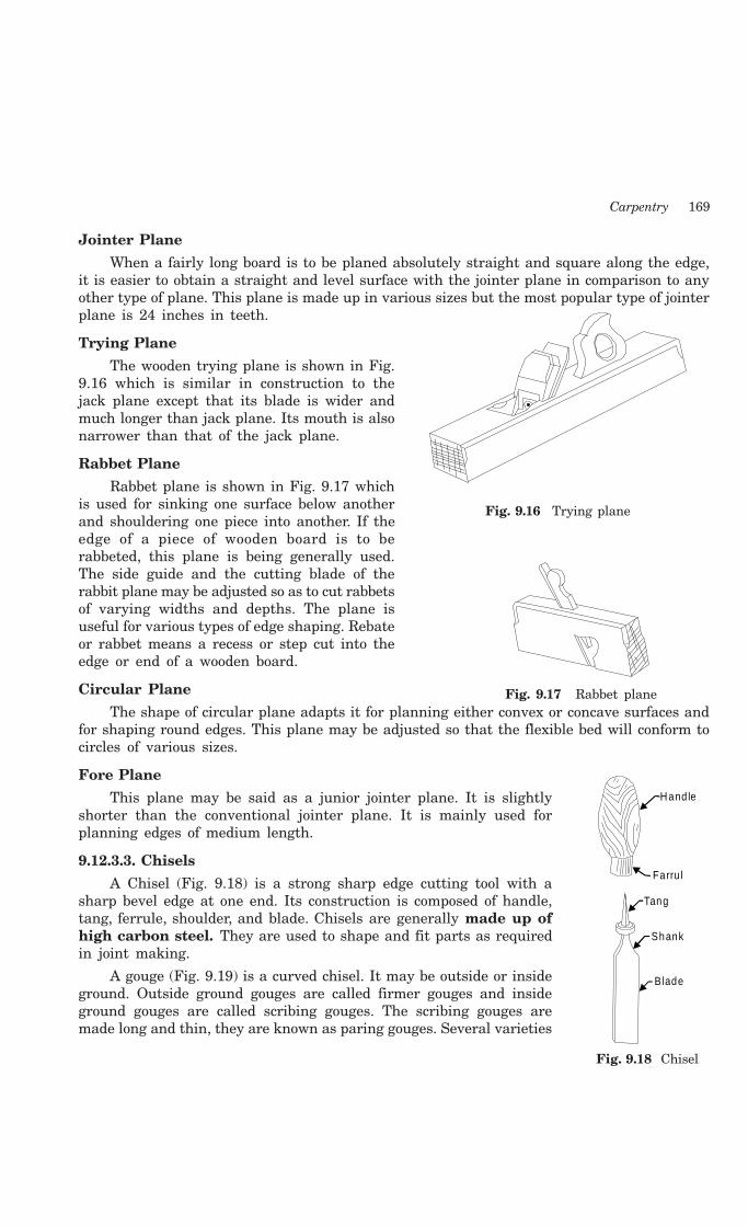
Carpentry 169
Jointer Plane
When a fairly long board is to be planed absolutely straight and square along the edge,it is easier to obtain a straight and level surface with the jointer plane in comparison to anyother type of plane. This plane is made up in various sizes but the most popular type of jointerplane is 24 inches in teeth.
Trying Plane
The wooden trying plane is shown in Fig.9.16 which is similar in construction to thejack plane except that its blade is wider andmuch longer than jack plane. Its mouth is alsonarrower than that of the jack plane.
Rabbet Plane
Rabbet plane is shown in Fig. 9.17 whichis used for sinking one surface below anotherand shouldering one piece into another. If theedge of a piece of wooden board is to berabbeted, this plane is being generally used.The side guide and the cutting blade of therabbit plane may be adjusted so as to cut rabbetsof varying widths and depths. The plane isuseful for various types of edge shaping. Rebateor rabbet means a recess or step cut into theedge or end of a wooden board.
Circular Plane
The shape of circular plane adapts it for planning either convex or concave surfaces andfor shaping round edges. This plane may be adjusted so that the flexible bed will conform tocircles of various sizes.
Fore Plane
This plane may be said as a junior jointer plane. It is slightlyshorter than the conventional jointer plane. It is mainly used forplanning edges of medium length.
9.12.3.3. Chisels
A Chisel (Fig. 9.18) is a strong sharp edge cutting tool with asharp bevel edge at one end. Its construction is composed of handle,tang, ferrule, shoulder, and blade. Chisels are generally made up ofhigh carbon steel. They are used to shape and fit parts as requiredin joint making.
A gouge (Fig. 9.19) is a curved chisel. It may be outside or insideground. Outside ground gouges are called firmer gouges and insideground gouges are called scribing gouges. The scribing gouges aremade long and thin, they are known as paring gouges. Several varieties
Fig. 9.16 Trying plane
Fig. 9.17 Rabbet plane
Hand le
Farru l
Tang
Shank
Blade
Fig. 9.18 Chisel
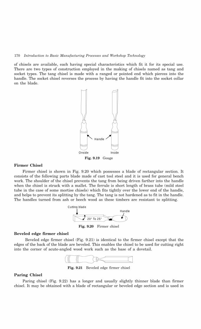
170 Introduction to Basic Manufacturing Processes and Workshop Technology
of chisels are available, each having special characteristics which fit it for its special use.There are two types of construction employed in the making of chisels named as tang andsocket types. The tang chisel is made with a ranged or pointed end which pierces into thehandle. The socket chisel reverses the process by having the handle fit into the socket collaron the blade.
Hand le
InsideO nside
Fig. 9.19 Gouge
Firmer Chisel
Firmer chisel is shown in Fig. 9.20 which possesses a blade of rectangular section. Itconsists of the following parts blade made of cast tool steel and it is used for general benchwork. The shoulder of the chisel prevents the tang from being driven farther into the handlewhen the chisel is struck with a mallet. The ferrule is short length of brass tube (mild steeltube in the case of some mortise chisels) which fits tightly over the lower end of the handle,and helps to prevent its splitting by the tang. The tang is not hardened as to fit in the handle.The handles turned from ash or beech wood as these timbers are resistant to splitting.
20° To 25°
Cutting blad eHand le
Fig. 9.20 Firmer chisel
Beveled edge firmer chisel
Beveled edge firmer chisel (Fig. 9.21) is identical to the firmer chisel except that theedges of the back of the blade are beveled. This enables the chisel to be used for cutting rightinto the corner of acute-angled wood work such as the base of a dovetail.
Fig. 9.21 Beveled edge firmer chisel
Paring Chisel
Paring chisel (Fig. 9.22) has a longer and usually slightly thinner blade than firmerchisel. It may be obtained with a blade of rectangular or beveled edge section and is used in

Carpentry 171
pattern making and where long accurate paring is required. The paring chisel should not bestruck with a mallet. This chisel is intended for manipulation by hand only, and not fordriving with a mallet like a firmer chisel for cutting of wooden jobs.
Fig. 9.22 Paring chisel
Mortise Chisel
Mortise chisel (Fig. 9.23) is designed for heavy work. A mortise chisel has a blade whichis very nearly square in section and so may be used as a lever for removing chips and willwithstand heavy blows from a mallet. Various types of handles are fitted to mortise chiseldepending upon use. Mortise chisel has an oval beech handle, whilst the heaviest type of allhas a socket handle. This socket replaces the ferrule and affords greater resistance to splittingwhen used for very heavy work. The leather washer acts as a shock absorber.
Hand leCutting Edge
Fig. 9.23 Mortise chisel
9.12.3.4. Scraper
The scraper for wooden work is used in carpentry shop. It is used after planning to obtaina smooth surface before final glass papering. Where the grain in wood is particularly twistyso that even a finely set plane tends to tear it, a sharp scraper will be found most useful totackle this problem. It is also used for cleaning up veneered work as its curved edges are usedfor cleaning up large molding of concave section and other similar work. The scraper is heldas the thumbs being positioned low down and pushed forward to curve the blade so that thecenter of the edge rather than the outer corners comes into contact with the surface of thewood. A sharp scraper will produce fine shavings on wooden surfaces.
9.12.3.5. Files and Rasps
Files and Rasps are shown in Fig. 9.24. They are of used for maintaining other woodworking tools and equipment. They are made of hardened tool steel which is tempered andthey should never be dropped as they are very brittle to break. They are of various typesdepending upon their size, shape, cuts and degree of their coarseness.
Hand leTangBlade
Fig. 9.24 Rasps
9.12.3.6. Adze
An adze (Fig. 9.25) is used for rough cutting, squaring, tochop inside curves and to produce concave surfaces. Its outerface is convex, inner face concave and edge is beveled to forma cutting edge. It is made of carbon steel.
Head
Hand le
Fig. 9.25 Adze
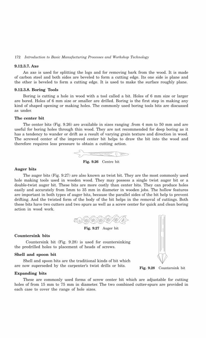
172 Introduction to Basic Manufacturing Processes and Workshop Technology
9.12.3.7. Axe
An axe is used for splitting the logs and for removing bark from the wood. It is madeof carbon steel and both sides are beveled to form a cutting edge. Its one side is plane andthe other is beveled to form a cutting edge. It is used to make the surface roughly plane.
9.12.3.8. Boring Tools
Boring is cutting a hole in wood with a tool called a bit. Holes of 6 mm size or largerare bored. Holes of 6 mm size or smaller are drilled. Boring is the first step in making anykind of shaped opening or making holes. The commonly used boring tools bits are discussedas under.
The center bit
The center bits (Fig. 9.26) are available in sizes ranging .from 4 mm to 50 mm and areuseful for boring holes through thin wood. They are not recommended for deep boring as ithas a tendency to wander or drift as a result of varying grain texture and direction in wood.The screwed center of the improved center bit helps to draw the bit into the wood andtherefore requires less pressure to obtain a cutting action.
Fig. 9.26 Centre bit
Auger bits
The auger bits (Fig. 9.27) are also known as twist bit. They are the most commonly usedhole making tools used in wooden wood. They may possess a single twist auger bit or adouble-twist auger bit. These bits are more costly than center bits. They can produce holeseasily and accurately from 5mm to 35 mm in diameter in wooden jobs. The hollow featuresare important in both types of auger bits, because the parallel sides of the bit help to preventdrifting. And the twisted form of the body of the bit helps in the removal of cuttings. Boththese bits have two cutters and two spurs as well as a screw center for quick and clean boringaction in wood work.
Fig. 9.27 Auger bit
Countersink bits
Countersink bit (Fig. 9.28) is used for countersinkingthe predrilled holes to placement of heads of screws.
Shell and spoon bit
Shell and spoon bits are the traditional kinds of bit whichare now superseded by the carpenter’s twist drills or bits.
Expanding bits
These are commonly used forms of screw center bit which are adjustable for cuttingholes of from 15 mm to 75 mm in diameter. The two combined cutter-spurs are provided ineach case to cover the range of hole sizes.
Fig. 9.28 Countersink bit
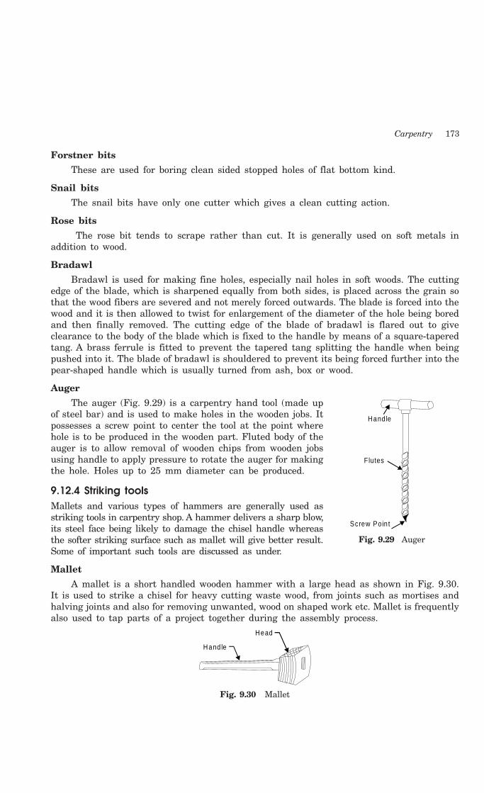
Carpentry 173
Forstner bits
These are used for boring clean sided stopped holes of flat bottom kind.
Snail bits
The snail bits have only one cutter which gives a clean cutting action.
Rose bits
The rose bit tends to scrape rather than cut. It is generally used on soft metals inaddition to wood.
Bradawl
Bradawl is used for making fine holes, especially nail holes in soft woods. The cuttingedge of the blade, which is sharpened equally from both sides, is placed across the grain sothat the wood fibers are severed and not merely forced outwards. The blade is forced into thewood and it is then allowed to twist for enlargement of the diameter of the hole being boredand then finally removed. The cutting edge of the blade of bradawl is flared out to giveclearance to the body of the blade which is fixed to the handle by means of a square-taperedtang. A brass ferrule is fitted to prevent the tapered tang splitting the handle when beingpushed into it. The blade of bradawl is shouldered to prevent its being forced further into thepear-shaped handle which is usually turned from ash, box or wood.
Auger
The auger (Fig. 9.29) is a carpentry hand tool (made upof steel bar) and is used to make holes in the wooden jobs. Itpossesses a screw point to center the tool at the point wherehole is to be produced in the wooden part. Fluted body of theauger is to allow removal of wooden chips from wooden jobsusing handle to apply pressure to rotate the auger for makingthe hole. Holes up to 25 mm diameter can be produced.
9.12.4 Striking toolsMallets and various types of hammers are generally used asstriking tools in carpentry shop. A hammer delivers a sharp blow,its steel face being likely to damage the chisel handle whereasthe softer striking surface such as mallet will give better result.Some of important such tools are discussed as under.
Mallet
A mallet is a short handled wooden hammer with a large head as shown in Fig. 9.30.It is used to strike a chisel for heavy cutting waste wood, from joints such as mortises andhalving joints and also for removing unwanted, wood on shaped work etc. Mallet is frequentlyalso used to tap parts of a project together during the assembly process.
Head
Hand le
Fig. 9.30 Mallet
Hand le
Flutes
Screw Po in t
Fig. 9.29 Auger
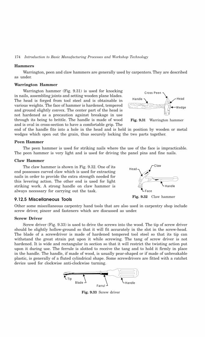
174 Introduction to Basic Manufacturing Processes and Workshop Technology
Hammers
Warrington, peen and claw hammers are generally used by carpenters. They are describedas under.
Warrington Hammer
Warrington hammer (Fig. 9.31) is used for knockingin nails, assembling joints and setting wooden plane blades.The head is forged from tool steel and is obtainable invarious weights. The face of hammer is hardened, temperedand ground slightly convex. The center part of the head isnot hardened as a precaution against breakage in usethrough its being to brittle. The handle is made of woodand is oval in cross-section to have a comfortable grip. Theend of the handle fits into a hole in the head and is held in position by wooden or metalwedges which open out the grain, thus securely locking the two parts together.
Peen Hammer
The peen hammer is used for striking nails where the use of the face is impracticable.The peen hammer is very light and is used for driving the panel pins and fine nails.
Claw Hammer
The claw hammer is shown in Fig. 9.32. One of itsend possesses curved claw which is used for extractingnails in order to provide the extra strength needed forthis levering action. The other end is used for lightstriking work. A strong handle on claw hammer isalways necessary for carrying out the task.
9.12.5 Miscellaneous ToolsOther some miscellaneous carpentry hand tools that are also used in carpentry shop includescrew driver, pincer and fasteners which are discussed as under.
Screw Driver
Screw driver (Fig. 9.33) is used to drive the screws into the wood. The tip of screw drivershould be slightly hollow-ground so that it will fit accurately in the slot in the screw-head.The blade of a screwdriver is made of hardened tempered tool steel so that its tip canwithstand the great strain put upon it while screwing. The tang of screw driver is nothardened. It is wide and rectangular in section so that it will restrict the twisting action putupon it during use. The ferrule is slotted to receive the tang and to hold it firmly in placein the handle. The handle, if made of wood, is usually pear-shaped or if made of unbreakableplastic, is generally of a fluted cylindrical shape. Some screwdrivers are fitted with a ratchetdevice used for clockwise anti-clockwise turning.
Hand leFarru l
B ladeTip
Fig. 9.33 Screw driver
HeadC law
Hand le
Face
Fig. 9.32 Claw hammer
Cross Peen
Hand le Head
W edge
Fig. 9.31 Warrington hammer

Carpentry 175
Pincer
Pincers are commonly used for withdrawing nails. They are made of cast steel, the jawsbeing hardened. The end of one of the arms is shaped to form a claw for removing nails. Thenail head is firmly gripped between the jaws as the long arms permit considerable pressureto be exerted by them. The nail is extracted from the wooden body by a leveling action, usingthe curved side of one of the jaws as a fulcrum. A small block of wood placed between thesteel jaw and the work prevents damage to the surface of the wood.
Various types and sizes of screws are available in different sizes from 6 mm to 150 mmand are sold in market by numbers. A hole is drilled before putting the screw and then sameis driven into former by means of a screw driver.
Bolts and nuts are used only where very heavy components are to be fastened togetherviz., wooden roof trusses and folding type furniture etc. The standard B.S.W. mild steel boltsand nuts are used.
9.13 COMMON WOOD JOINTS
All wooden objects whether doors, windows, furniture, pattern, core boxes, handicrafts, toys,cots, etc., are all assembled with joints. The various common used wood working joints aregiven through Fig. 9.34 to Fig. 9.41.
G roove
Tongue
A
B
A
B
Fig. 9.34 Groove and tongue joint Fig. 9.35 Mortise and tennon joint
A A
B
BBB
A
A
Fig. 9.36 T-lap joint Fig. 9.37 Open or through dove-tail joint
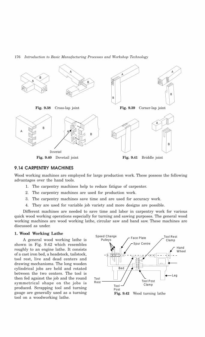
176 Introduction to Basic Manufacturing Processes and Workshop Technology
A
A
B
B
Fig. 9.38 Cross-lap joint Fig. 9.39 Corner-lap joint
AB
AB
Doveta il
A
B
Fig. 9.40 Dovetail joint Fig. 9.41 Briddle joint
9.14 CARPENTRY MACHINES
Wood working machines are employed for large production work. These possess the followingadvantages over the hand tools.
1. The carpentry machines help to reduce fatigue of carpenter.
2. The carpentry machines are used for production work.
3. The carpentry machines save time and are used for accuracy work.
4. They are used for variable job variety and more designs are possible.
Different machines are needed to save time and labor in carpentry work for variousquick wood working operations especially for turning and sawing purposes. The general woodworking machines are wood working lathe, circular saw and band saw. These machines arediscussed as under.
1. Wood Working Lathe
A general wood working lathe isshown in Fig. 9.42 which resemblesroughly to an engine lathe. It consistsof a cast iron bed, a headstock, tailstock,tool rest, live and dead centers anddrawing mechanisms. The long woodencylindrical jobs are held and rotatedbetween the two centers. The tool isthen fed against the job and the roundsymmetrical shape on the jobs isproduced. Scrapping tool and turninggauge are generally used as a turningtool on a woodworking lathe.
Too lPost
Too lRest
Bed
Too l P ostC lam p
Leg
Face P la te
Spur Centre
Speed ChangePulleys
HandW heel
Too l RestC lam p
Fig. 9.42 Wood turning lathe
A
B
A
B
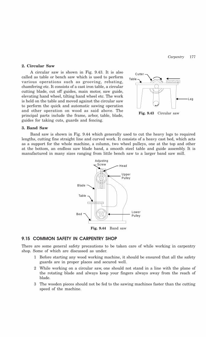
Carpentry 177
2. Circular Saw
A circular saw is shown in Fig. 9.43. It is alsocalled as table or bench saw which is used to performvarious operations such as grooving, rebating,chamfering etc. It consists of a cast iron table, a circularcutting blade, cut off guides, main motor, saw guide,elevating hand wheel, tilting hand wheel etc. The workis held on the table and moved against the circular sawto perform the quick and automatic sawing operationand other operation on wood as said above. Theprincipal parts include the frame, arbor, table, blade,guides for taking cuts, guards and fencing.
3. Band Saw
Band saw is shown in Fig. 9.44 which generally used to cut the heavy logs to requiredlengths, cutting fine straight line and curved work. It consists of a heavy cast bed, which actsas a support for the whole machine, a column, two wheel pulleys, one at the top and otherat the bottom, an endless saw blade band, a smooth steel table and guide assembly. It ismanufactured in many sizes ranging from little bench saw to a larger band saw mill.
AdjustingScrew Head
UpperPu lley
B lade
Tab le
BedLowerPu lley
Fig. 9.44 Band saw
9.15 COMMON SAFETY IN CARPENTRY SHOP
There are some general safety precautions to be taken care of while working in carpentryshop. Some of which are discussed as under.
1 Before starting any wood working machine, it should be ensured that all the safetyguards are in proper places and secured well.
2 While working on a circular saw, one should not stand in a line with the plane ofthe rotating blade and always keep your fingers always away from the reach ofblade.
3 The wooden pieces should not be fed to the sawing machines faster than the cuttingspeed of the machine.
Tab le
Cutte r
Leg
Fig. 9.43 Circular saw

178 Introduction to Basic Manufacturing Processes and Workshop Technology
4 While working on wood lathes, the job should be properly held.
5 One should not use defective or damaged carpentry tools while carrying out carpentrywork.
6 Nails, screws should be properly kept in a box for proper house keeping.
7 Sufficient safety precautions are to be taken for preventing fire in the carpentryshop.
8 No carpentry tools should be thrown for saving time in handling.
9.16 QUESTIONS1. What is the difference between hard and soft wood?
2. Describe the various methods of seasoning of timber.
3. Define exogenous trees and endogenous trees.
4. What is the difference between wood and timber?
5. Describe the various methods of conversion of timber.
6. What are the characteristics of a good timber?
7. Sketch the cross-section of an exogenous tree. Discuss the various parts of this tree.
8. Explain in brief the various defects in timber.
9. Describe a few methods of preservation of timber in brief, and why is it necessary?
10. What are the commercial sizes in which the timber is sold in the market?
11. Explain in brief with neat sketches the various types of measuring tools used in carpentryshop.
12. Discuss briefly with neat sketches the various types of cutting tools used in carpentry shop.
13. Discuss briefly the setting and sharpening of a carpentry tool.
14. Discuss briefly the various boring tools used in a carpentry tool.
15. Discuss briefly with neat sketches the various planning and striking tools.
16. Sketch the various wood working joints.
17. Explain the following carpentry processes in brief.
(i) Marking (ii) Sawing, (iii) Planning
(iv) Boring, (v) Grooving, (vi) Chiseling
18. Explain the following wood working machines in brief.
(i) Wooden lathe, (ii) Circular saw
(iii) Band saw, (iv) Planer
19. What are the general safety measures used in carpentry shop?

179
PATTERN AND CORE MAKING
10.1 PATTERN
A pattern is a model or the replica of the object (to be casted). It is embedded in molding sandand suitable ramming of molding sand around the pattern is made. The pattern is thenwithdrawn for generating cavity (known as mold) in molding sand. Thus it is a mould formingtool. Pattern can be said as a model or the replica of the object to be cast except for thevarious al1owances a pattern exactly resembles the casting to be made. It may be defined asa model or form around which sand is packed to give rise to a cavity known as mold cavityin which when molten metal is poured, the result is the cast object. When this mould/cavityis filled with molten metal, molten metal solidifies and produces a casting (product). So thepattern is the replica of the casting.
A pattern prepares a mold cavity for the purpose of making a casting. It may also possessprojections known as core prints for producing extra recess in the mould for placement of coreto produce hol1owness in casting. It may help in establishing seat for placement of core atlocating points on the mould in form of extra recess. It establishes the parting line andparting surfaces in the mold. It may help to position a core in case a part of mold cavity ismade with cores, before the molding sand is rammed. It should have finished and smoothsurfaces for reducing casting defects. Runner, gates and risers used for introducing andfeeding molten metal to the mold cavity may sometimes form the parts of the pattern. Thefirst step in casting is pattern making. The pattern is a made of suitable material and is usedfor making cavity called mould in molding sand or other suitable mould materials. When thismould is filled with molten metal and it is allowed to solidify, it forms a reproduction of the,pattern which is known as casting. There are some objectives of a pattern which are givenas under.
OBJECTIVES OF A PATTERN
1 Pattern prepares a mould cavity for the purpose of making a casting.
2 Pattern possesses core prints which produces seats in form of extra recess for coreplacement in the mould.
3 It establishes the parting line and parting surfaces in the mould.
4 Runner, gates and riser may form a part of the pattern.
10CHAPTER
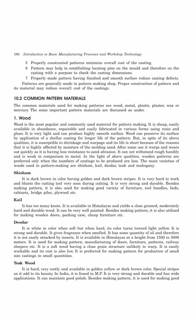
180 Introduction to Basic Manufacturing Processes and Workshop Technology
5 Properly constructed patterns minimize overall cost of the casting.6 Pattern may help in establishing locating pins on the mould and therefore on the
casting with a purpose to check the casting dimensions.7 Properly made pattern having finished and smooth surface reduce casting defects.
Patterns are generally made in pattern making shop. Proper construction of pattern andits material may reduce overal1 cost of the castings.
10.2 COMMON PATTERN MATERIALS
The common materials used for making patterns are wood, metal, plastic, plaster, wax ormercury. The some important pattern materials are discussed as under.
1. WoodWood is the most popular and commonly used material for pattern making. It is cheap, easilyavailable in abundance, repairable and easily fabricated in various forms using resin andglues. It is very light and can produce highly smooth surface. Wood can preserve its surfaceby application of a shellac coating for longer life of the pattern. But, in spite of its abovequalities, it is susceptible to shrinkage and warpage and its life is short because of the reasonsthat it is highly affected by moisture of the molding sand. After some use it warps and wearsout quickly as it is having less resistance to sand abrasion. It can not withstand rough handilyand is weak in comparison to metal. In the light of above qualities, wooden patterns arepreferred only when the numbers of castings to be produced are less. The main varieties ofwoods used in pattern-making are shisham, kail, deodar, teak and mahogany.
Shisham
It is dark brown in color having golden and dark brown stripes. It is very hard to workand blunts the cutting tool very soon during cutting. It is very strong and durable. Besidesmaking pattern, it is also used for making good variety of furniture, tool handles, beds,cabinets, bridge piles, plywood etc.
Kail
It has too many knots. It is available in Himalayas and yields a close grained, moderatelyhard and durable wood. It can be very well painted. Besides making pattern, it is also utilizedfor making wooden doors, packing case, cheap furniture etc.
Deodar
It is white in color when soft but when hard, its color turns toward light yellow. It isstrong and durable. It gives fragrance when smelled. It has some quantity of oil and thereforeit is not easily attacked by insects. It is available in Himalayas at a height from 1500 to 3000meters. It is used for making pattern, manufacturing of doors, furniture, patterns, railwaysleepers etc. It is a soft wood having a close grain structure unlikely to warp. It is easilyworkable and its cost is also low. It is preferred for making pattern for production of smallsize castings in small quantities.
Teak Wood
It is hard, very costly and available in golden yellow or dark brown color. Special stripeson it add to its beauty. In India, it is found in M.P. It is very strong and durable and has wideapplications. It can maintain good polish. Besides making pattern, it is used for making good

Pattern and Core Making 181
quality furniture, plywood, ships etc. It is a straight-grained light wood. It is easily workableand has little tendency to warp. Its cost is moderate.
Mahogany
This is a hard and strong wood. Patterns made of this wood are more durable than thoseof above mentioned woods and they are less likely to warp. It has got a uniform straight grainstructure and it can be easily fabricated in various shapes. It is costlier than teak and pine wood,It is generally not preferred for high accuracy for making complicated pattern. It is also preferredfor production of small size castings in small quantities. The other Indian woods which may alsobe used for pattern making are deodar, walnllt, kail, maple, birch, cherry and shisham.
Advantages of wooden patterns
1 Wood can be easily worked.
2 It is light in weight.
3 It is easily available.
4 It is very cheap.
5 It is easy to join.
6 It is easy to obtain good surface finish.
7 Wooden laminated patterns are strong.
8 It can be easily repaired.
Disadvantages
1 It is susceptible to moisture.
2 It tends to warp.
3 It wears out quickly due to sand abrasion.
4 It is weaker than metallic patterns.
2. MetalMetallic patterns are preferred when the number of castings required is large enough to justifytheir use. These patterns are not much affected by moisture as wooden pattern. The wear andtear of this pattern is very less and hence posses longer life. Moreover, metal is easier to shapethe pattern with good precision, surface finish and intricacy in shapes. It can withstand againstcorrosion and handling for longer period. It possesses excellent strength to weight ratio. Themain disadvantages of metallic patterns are higher cost, higher weight and tendency of rusting.It is preferred for production of castings in large quantities with same pattern. The metalscommonly used for pattern making are cast iron, brass and bronzes and aluminum alloys.
Cast Iron
It is cheaper, stronger, tough, and durable and can produce a smooth surface finish. Italso possesses good resistance to sand abrasion. The drawbacks of cast iron patterns are thatthey are hard, heavy, brittle and get rusted easily in presence of moisture.
Advantages
1. It is cheap
2. It is easy to file and fit
182 Introduction to Basic Manufacturing Processes and Workshop Technology
3. It is strong
4. It has good resistance against sand abrasion
5. Good surface finish
Disadvantages
1 It is heavy
2 It is brittle and hence it can be easily broken
3 It may rust
Brasses and Bronzes
These are heavier and expensive than cast iron and hence are preferred for manufacturingsmall castings. They possess good strength, machinability and resistance to corrosion andwear. They can produce a better surface finish. Brass and bronze pattern is finding applicationin making match plate pattern
Advantages
1. Better surface finish than cast iron.
2. Very thin sections can be easily casted.
Disadvantages1. It is costly2. It is heavier than cast iron.
Aluminum Alloys
Aluminum alloy patterns are more popular and best among all the metallic patternsbecause of their high light ness, good surface finish, low melting point and good strength.They also possesses good resistance to corrosion and abrasion by sand and there by enhancinglonger life of pattern. These materials do not withstand against rough handling. These havepoor repair ability and are preferred for making large castings.
Advantages1. Aluminum alloys pattern does not rust.2. They are easy to cast.3. They are light in weight.4. They can be easily machined.
Disadvantages1. They can be damaged by sharp edges.2. They are softer than brass and cast iron.3. Their storing and transportation needs proper care.
White Metal (Alloy of Antimony, Copper and Lead)
Advantages
1. It is best material for lining and stripping plates.2. It has low melting point around 260°C3. It can be cast into narrow cavities.

Pattern and Core Making 183
Disadvantages
1. It is too soft.
2. Its storing and transportation needs proper care
3. It wears away by sand or sharp edges.
3. PlasticPlastics are getting more popularity now a days because the patterns made of these materialsare lighter, stronger, moisture and wear resistant, non sticky to molding sand, durable andthey are not affected by the moisture of the molding sand. Moreover they impart very smoothsurface finish on the pattern surface. These materials are somewhat fragile, less resistant tosudden loading and their section may need metal reinforcement. The plastics used for thispurpose are thermosetting resins. Phenolic resin plastics are commonly used. These areoriginally in liquid form and get solidified when heated to a specified temperature. To preparea plastic pattern, a mould in two halves is prepared in plaster of paris with the help of awooden pattern known as a master pattern. The phenolic resin is poured into the mould andthe mould is subjected to heat. The resin solidifies giving the plastic pattern. Recently a newmaterial has stepped into the field of plastic which is known as foam plastic. Foam plastic isnow being produced in several forms and the most common is the expandable polystyreneplastic category. It is made from benzene and ethyl benzene.
4. PlasterThis material belongs to gypsum family which can be easily cast and worked with woodentools and preferable for producing highly intricate casting. The main advantages of plaster arethat it has high compressive strength and is of high expansion setting type which compensatefor the shrinkage allowance of the casting metal. Plaster of paris pattern can be preparedeither by directly pouring the slurry of plaster and water in moulds prepared earlier from amaster pattern or by sweeping it into desired shape or form by the sweep and stricklemethod. It is also preferred for production of small size intricate castings and making coreboxes.
5. WaxPatterns made from wax are excellent for investment casting process. The materials usedare blends of several types of waxes, and other additives which act as polymerizing agents,stabilizers, etc. The commonly used waxes are paraffin wax, shellac wax, bees-wax, cerasinwax, and micro-crystalline wax. The properties desired in a good wax pattern include lowash content up to 0.05 per cent, resistant to the primary coat material used for investment,high tensile strength and hardness, and substantial weld strength. The general practice ofmaking wax pattern is to inject liquid or semi-liquid wax into a split die. Solid injection isalso used to avoid shrinkage and for better strength. Waxes use helps in imparting a highdegree of surface finish and dimensional accuracy castings. Wax patterns are prepared bypouring heated wax into split moulds or a pair of dies. The dies after having been cooleddown are parted off. Now the wax pattern is taken out and used for molding. Suchpatterns need not to be drawn out solid from the mould. After the mould is ready, the waxis poured out by heating the mould and keeping it upside down. Such patterns aregenerally used in the process of investment casting where accuracy is linked with intricacyof the cast object.

184 Introduction to Basic Manufacturing Processes and Workshop Technology
10.3 FACTORS EFFECTING SELECTION OF PATTERN MATERIAL
The following factors must be taken into consideration while selecting pattern materials.
1. Number of castings to be produced. Metal pattern are preferred when castings arerequired large in number.
2. Type of mould material used.
3. Kind of molding process.
4. Method of molding (hand or machine).
5. Degree of dimensional accuracy and surface finish required.
6. Minimum thickness required.
7. Shape, complexity and size of casting.
8. Cost of pattern and chances of repeat orders of the pattern
10.4 TYPES OF PATTERN
The types of the pattern and the description of each are given as under.
1. One piece or solid pattern
2. Two piece or split pattern
3. Cope and drag pattern
4. Three-piece or multi- piece pattern
5. Loose piece pattern
6. Match plate pattern
7. Follow board pattern
8. Gated pattern
9. Sweep pattern
10. Skeleton pattern
11. Segmental or part pattern
1. Single-piece or solid patternSolid pattern is made of single piece without joints, partingslines or loose pieces. It is the simplest form of the pattern.Typical single piece pattern is shown in Fig. 10.1.
2. Two-piece or split patternWhen solid pattern is difficult forwithdrawal from the mold cavity, thensolid pattern is splited in two parts. Splitpattern is made in two pieces whichare joined at the parting line by meansof dowel pins. The splitting at theparting line is done to facilitate thewithdrawal of the pattern. A typicalexample is shown in Fig. 10.2.
Fig. 10.1 Single piee pattern
�����������
��������
Fig. 10.2 Two piece pattern
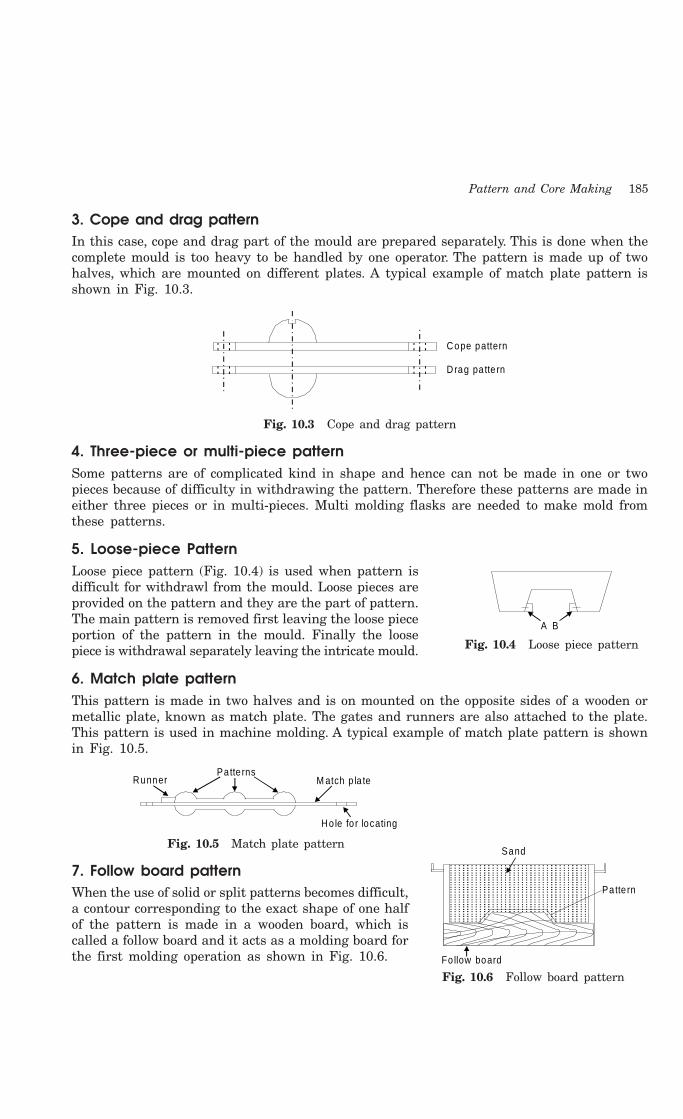
Pattern and Core Making 185
3. Cope and drag patternIn this case, cope and drag part of the mould are prepared separately. This is done when thecomplete mould is too heavy to be handled by one operator. The pattern is made up of twohalves, which are mounted on different plates. A typical example of match plate pattern isshown in Fig. 10.3.
Cope pattern
Drag pa tte rn
Fig. 10.3 Cope and drag pattern
4. Three-piece or multi-piece patternSome patterns are of complicated kind in shape and hence can not be made in one or twopieces because of difficulty in withdrawing the pattern. Therefore these patterns are made ineither three pieces or in multi-pieces. Multi molding flasks are needed to make mold fromthese patterns.
5. Loose-piece PatternLoose piece pattern (Fig. 10.4) is used when pattern isdifficult for withdrawl from the mould. Loose pieces areprovided on the pattern and they are the part of pattern.The main pattern is removed first leaving the loose pieceportion of the pattern in the mould. Finally the loosepiece is withdrawal separately leaving the intricate mould.
6. Match plate patternThis pattern is made in two halves and is on mounted on the opposite sides of a wooden ormetallic plate, known as match plate. The gates and runners are also attached to the plate.This pattern is used in machine molding. A typical example of match plate pattern is shownin Fig. 10.5.
Hole fo r locating
M atch p la tePatte rns
Runner
Fig. 10.5 Match plate pattern
7. Follow board patternWhen the use of solid or split patterns becomes difficult,a contour corresponding to the exact shape of one halfof the pattern is made in a wooden board, which iscalled a follow board and it acts as a molding board forthe first molding operation as shown in Fig. 10.6. Fo llow board
Patte rn
Sand
Fig. 10.6 Follow board pattern
A B
Fig. 10.4 Loose piece pattern
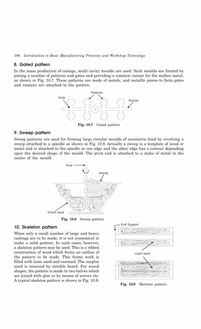
186 Introduction to Basic Manufacturing Processes and Workshop Technology
8. Gated patternIn the mass production of casings, multi cavity moulds are used. Such moulds are formed byjoining a number of patterns and gates and providing a common runner for the molten metal,as shown in Fig. 10.7. These patterns are made of metals, and metallic pieces to form gatesand runners are attached to the pattern.
G ate
Patte rns
Runner
Fig. 10.7 Gated pattern
9. Sweep patternSweep patterns are used for forming large circular moulds of symmetric kind by revolving asweep attached to a spindle as shown in Fig. 10.8. Actually a sweep is a template of wood ormetal and is attached to the spindle at one edge and the other edge has a contour dependingupon the desired shape of the mould. The pivot end is attached to a stake of metal in thecenter of the mould.
G reen sand
Post
Sweep
Fig. 10.8 Sweep pattern
10. Skeleton patternWhen only a small number of large and heavycastings are to be made, it is not economical tomake a solid pattern. In such cases, however,a skeleton pattern may be used. This is a ribbedconstruction of wood which forms an outline ofthe pattern to be made. This frame work isfilled with loam sand and rammed. The surplussand is removed by strickle board. For roundshapes, the pattern is made in two halves whichare joined with glue or by means of screws etc.A typical skeleton pattern is shown in Fig. 10.9.
End Support
Loam sand
Fig. 10.9 Skeleton pattern
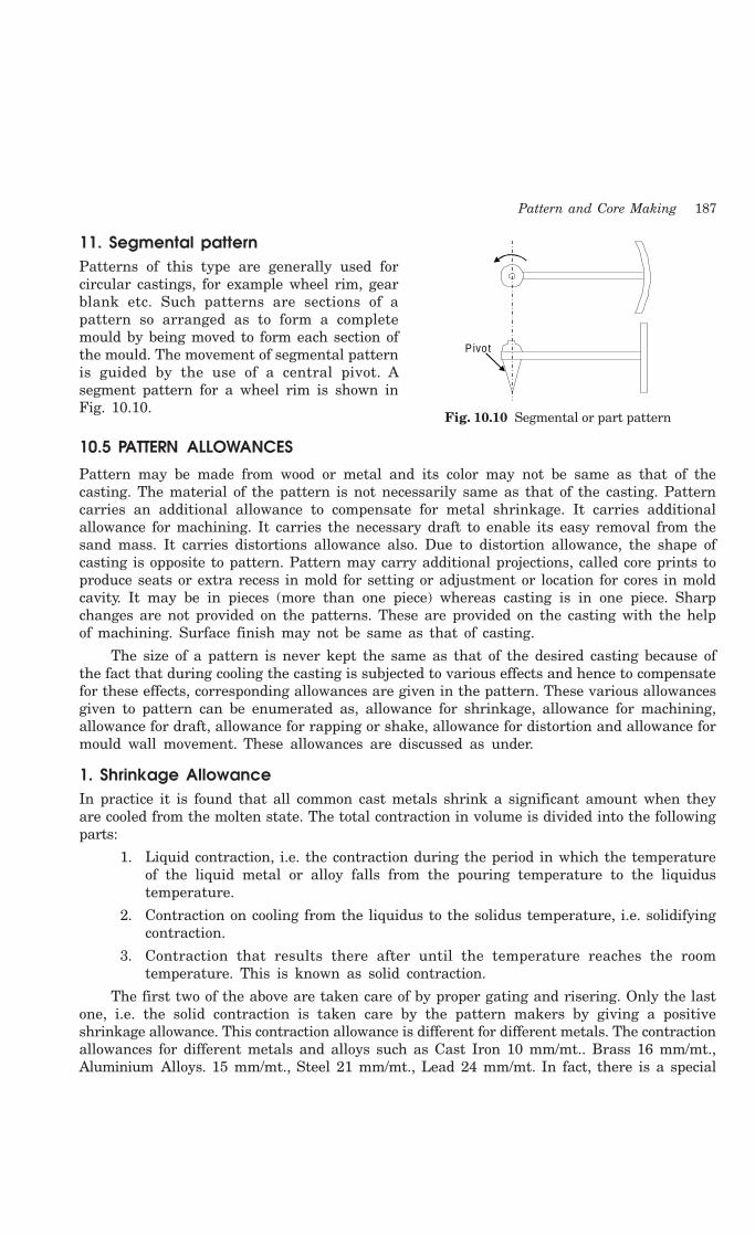
Pattern and Core Making 187
11. Segmental patternPatterns of this type are generally used forcircular castings, for example wheel rim, gearblank etc. Such patterns are sections of apattern so arranged as to form a completemould by being moved to form each section ofthe mould. The movement of segmental patternis guided by the use of a central pivot. Asegment pattern for a wheel rim is shown inFig. 10.10.
10.5 PATTERN ALLOWANCES
Pattern may be made from wood or metal and its color may not be same as that of thecasting. The material of the pattern is not necessarily same as that of the casting. Patterncarries an additional allowance to compensate for metal shrinkage. It carries additionalallowance for machining. It carries the necessary draft to enable its easy removal from thesand mass. It carries distortions allowance also. Due to distortion allowance, the shape ofcasting is opposite to pattern. Pattern may carry additional projections, called core prints toproduce seats or extra recess in mold for setting or adjustment or location for cores in moldcavity. It may be in pieces (more than one piece) whereas casting is in one piece. Sharpchanges are not provided on the patterns. These are provided on the casting with the helpof machining. Surface finish may not be same as that of casting.
The size of a pattern is never kept the same as that of the desired casting because ofthe fact that during cooling the casting is subjected to various effects and hence to compensatefor these effects, corresponding allowances are given in the pattern. These various allowancesgiven to pattern can be enumerated as, allowance for shrinkage, allowance for machining,allowance for draft, allowance for rapping or shake, allowance for distortion and allowance formould wall movement. These allowances are discussed as under.
1. Shrinkage AllowanceIn practice it is found that all common cast metals shrink a significant amount when theyare cooled from the molten state. The total contraction in volume is divided into the followingparts:
1. Liquid contraction, i.e. the contraction during the period in which the temperatureof the liquid metal or alloy falls from the pouring temperature to the liquidustemperature.
2. Contraction on cooling from the liquidus to the solidus temperature, i.e. solidifyingcontraction.
3. Contraction that results there after until the temperature reaches the roomtemperature. This is known as solid contraction.
The first two of the above are taken care of by proper gating and risering. Only the lastone, i.e. the solid contraction is taken care by the pattern makers by giving a positiveshrinkage allowance. This contraction allowance is different for different metals. The contractionallowances for different metals and alloys such as Cast Iron 10 mm/mt.. Brass 16 mm/mt.,Aluminium Alloys. 15 mm/mt., Steel 21 mm/mt., Lead 24 mm/mt. In fact, there is a special
Pivo t
Fig. 10.10 Segmental or part pattern
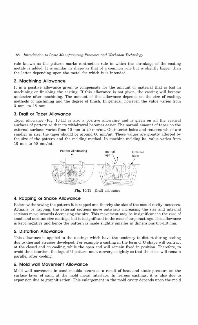
188 Introduction to Basic Manufacturing Processes and Workshop Technology
rule known as the pattern marks contraction rule in which the shrinkage of the castingmetals is added. It is similar in shape as that of a common rule but is slightly bigger thanthe latter depending upon the metal for which it is intended.
2. Machining AllowanceIt is a positive allowance given to compensate for the amount of material that is lost inmachining or finishing the casting. If this allowance is not given, the casting will becomeundersize after machining. The amount of this allowance depends on the size of casting,methods of machining and the degree of finish. In general, however, the value varies from3 mm. to 18 mm.
3. Draft or Taper AllowanceTaper allowance (Fig. 10.11) is also a positive allowance and is given on all the verticalsurfaces of pattern so that its withdrawal becomes easier. The normal amount of taper on theexternal surfaces varies from 10 mm to 20 mm/mt. On interior holes and recesses which aresmaller in size, the taper should be around 60 mm/mt. These values are greatly affected bythe size of the pattern and the molding method. In machine molding its, value varies from10 mm to 50 mm/mt.
Patte rn w ithdraw ing In te rna ltaper
Exte rna ltaper
Fig. 10.11 Draft allowance
4. Rapping or Shake AllowanceBefore withdrawing the pattern it is rapped and thereby the size of the mould cavity increases.Actually by rapping, the external sections move outwards increasing the size and internalsections move inwards decreasing the size. This movement may be insignificant in the case ofsmall and medium size castings, but it is significant in the case of large castings. This allowanceis kept negative and hence the pattern is made slightly smaller in dimensions 0.5-1.0 mm.
5. Distortion AllowanceThis allowance is applied to the castings which have the tendency to distort during coolingdue to thermal stresses developed. For example a casting in the form of U shape will contractat the closed end on cooling, while the open end will remain fixed in position. Therefore, toavoid the distortion, the legs of U pattern must converge slightly so that the sides will remainparallel after cooling.
6. Mold wall Movement AllowanceMold wall movement in sand moulds occurs as a result of heat and static pressure on thesurface layer of sand at the mold metal interface. In ferrous castings, it is also due toexpansion due to graphitisation. This enlargement in the mold cavity depends upon the mold

Pattern and Core Making 189
density and mould composition. This effect becomes more pronounced with increase in moisturecontent and temperature.
10.6 CORE AND CORE BOX
Cores are compact mass of core sand that when placed in mould cavity at required locationwith proper alignment does not allow the molten metal to occupy space for solidification inthat portion and hence help to produce hollowness in the casting. The environment in whichthe core is placed is much different from that of the mold. In fact the core (Fig. 10.12) hasto withstand the severe action of hot metal which completely surrounds it. Cores are classifiedaccording to shape and position in the mold. There are various types of cores such ashorizontal core (Fig. 10.13), vertical core (Fig. 10.14), balanced core (Fig. 10.15), drop core(Fig. 10.16) and hanging core (Fig. 10.17).
BakedCore
PartingL ine
SandM oldCavity
Fig. 10.12 Horizontal core
Dry sand core
M ou ld Cavity
Cope
Drag
Sand
PartingL ine
Core
M ou ld
Fig. 10.13 Vertical core Fig. 10.14 Balanced core
M ould
Fig. 10.15 Drop core Fig. 10.16 Hanging core
There are various functions of cores which are given below
1. Core is used to produce hollowness in castings in form of internal cavities.
2. It may form a part of green sand mold
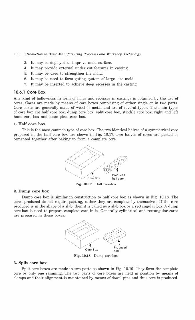
190 Introduction to Basic Manufacturing Processes and Workshop Technology
3. It may be deployed to improve mold surface.4. It may provide external under cut features in casting.5. It may be used to strengthen the mold.6. It may be used to form gating system of large size mold7. It may be inserted to achieve deep recesses in the casting
10.6.1 Core BoxAny kind of hollowness in form of holes and recesses in castings is obtained by the use ofcores. Cores are made by means of core boxes comprising of either single or in two parts.Core boxes are generally made of wood or metal and are of several types. The main typesof core box are half core box, dump core box, split core box, strickle core box, right and lefthand core box and loose piece core box.
1. Half core box
This is the most common type of core box. The two identical halves of a symmetrical coreprepared in the half core box are shown in Fig. 10.17. Two halves of cores are pasted orcemented together after baking to form a complete core.
Core BoxProducedhalf core
Fig. 10.17 Half core-box
2. Dump core box
Dump core box is similar in construction to half core box as shown in Fig. 10.18. Thecores produced do not require pasting, rather they are complete by themselves. If the coreproduced is in the shape of a slab, then it is called as a slab box or a rectangular box. A dumpcore-box is used to prepare complete core in it. Generally cylindrical and rectangular coresare prepared in these boxes.
ProducedcoreCore Box
Fig. 10.18 Dump core-box
3. Split core box
Split core boxes are made in two parts as shown in Fig. 10.19. They form the completecore by only one ramming. The two parts of core boxes are held in position by means ofclamps and their alignment is maintained by means of dowel pins and thus core is produced.

Pattern and Core Making 191
Core box
Producedcore
Dowel pins
Fig. 10.19 Split core-box
4. Right and left hand core box
Some times the cores are not symmetrical about the center line. In such cases, right andleft hand core boxes are used. The two halves of a core made in the same core box are notidentical and they cannot be pasted together.
5. Strickle core box
This type of core box is used when a core with an irregular shape is desired. Therequired shape is achieved by striking oft the core sand from the top of the core box with awooden piece, called as strickle board. The strickle board has the same contour as that of therequired core.
6. Loose piece core box
Loose piece core boxes are highly suitable for making cores where provision for bosses,hubs etc. is required. In such cases, the loose pieces may be located by dowels, nails anddovetails etc. In certain cases, with the help of loose pieces, a single core box can be madeto generate both halves of the right-left core.
10.7 CORE BOX ALLOWANCES
Materials used in making core generally swell and increase in size. This may lead toincrease the size of core. The larger cores sometimes tend to become still larger. Thisincrease in size may not be significant in small cores, but it is quite significant in large coresand therefore certain amount of allowance should be given on the core boxes to compensatefor this increase the cores. It is not possible to lay down a rule for the amount of thisallowance as this will depend upon the material used, but it is customary to give a negativeallowance of 5 mm /mt.
10.8 COLOR CODIFICATION FOR PATTERNS AND CORE BOXES
There is no set or accepted standard for representing of various surfaces of pattern andcore boxes by different colors. The practice of representing of various pattern surfaces bydifferent colors varies with from country to country and sometimes with different manufactureswithin the country. Out of the various color codifications, the American practice is the mostpopular. In this practice, the color identification is as follows. Surfaces to be left unfinishedafter casting are to be painted as black. Surface to be machined are painted as red. Core
192 Introduction to Basic Manufacturing Processes and Workshop Technology
prints are painted as yellow. Seats for loose pieces are painted as red stripes on yellowbackground. Stop-offs is painted as black stripes on yellow base.
10.9 CORE PRINTS
When a hole blind or through is needed in the casting, a core is placed in the mouldcavity to produce the same. The core has to be properly located or positioned in the mouldcavity on pre-formed recesses or impressions in the sand. To form these recesses or impressionsfor generating seat for placement of core, extra projections are added on the pattern surfaceat proper places. These extra projections on the pattern (used for producing recesses in themould for placement of cores at that location) are known as core prints. Core prints may beof horizontal, vertical, balanced, wing and core types. Horizontal core print produces seats forhorizontal core in the mould. Vertical core print produces seats to support a vertical core inthe mould. Balanced core print produces a single seat on one side of the mould and the coreremains partly in this formed seat and partly in the mould cavity, the two portions balancingeach other. The hanging portion of the core may be supported on chaplets. Wing core printis used to form a seat for a wing core. Cover core print forms seat to support a cover core.
10.10 WOODEN PATTERN AND WOODEN CORE BOX MAKING TOOLS
The job of patternmaker is basically done by a carpenter. The tools required for makingpatterns, therefore do not much differ from those used by a carpenter, excepting the specialtools as per the needs of the trade. In addition to tools used by a carpenter, there is one moretool named as the contraction rule, which is a measuring tool of the patternmaker’s trade.All castings shrinks during cooling from the molten state, and patterns have to be madecorrespondingly larger than the required casting in order to compensate for the loss in sizedue to this shrinkage. Various metals and alloys have various shrinkages. The allowance forshrinkage, therefore, varies with various metals and also according to particular castingconditions, and hence the size of the pattern is proportionally increased. A separate scale isavailable for each allowance, and it enables the dimensions to be set out directly during layingout of the patterns. The rule usually employed the one that has two scales on each side, thetotal number of scales being four for four commonly cast metals namely, steel, cast iron, brassand aluminum. To compensate for contraction or shrinkage, the graduations are oversized bya proportionate amount, e.g. on 1 mm or 1 per cent scale each 100 cm is longer by 1 cm.The general tools and equipment used in the pattern making shop are given as under.
1. Measuring and Layout Tools1. Wooden or steel scale or rule 2. Dividers
3. Calipers 4. Try square
5. Caliper rule 6. Flexible rule
7. Marking gauge 8. T-bevel
9. Combination square
2. Sawing Tools1. Compass saw 2. Rip saw
3. Coping saw 4. Dovetail saw

Pattern and Core Making 193
5. Back saw 6. Panel saw
7. Miter saw
3. Planning Tools1. Jack plane 2. Circular plane
3. Router plane 4. Rabbet plane
5. Block plane 6. Bench plane
7. Core box plane
4. Boring Tools1. Hand operated drills 2. Machine operated drills
3. Twist drill 4. Countersunk
5. Brace 6. Auger bit
7. Bit gauge
5. Clamping Tools1. Bench vice 2. C-clamp3. Bar clamp 4. Hand screw5. Pattern maker’s vice 6. Pinch dog
6. Miscellaneous Tools1. Screw Driver 2. Vaious types of hammers
3. Chisel 4. Rasp
5. File 6. Nail set
7. Screw driver 8. Bradawl
9. Brad pusher 10. Cornering tool
10.11 WOODEN PATTERN AND WOODEN CORE BOX MAKING MACHINES
Modern wooden pattern and wooden core making shop requires various wood working machinesfor quick and mass production of patterns and core boxes. Some of the commonly machinesused in making patterns and coreboxes of various kinds of wood are discussed as under.
1. Wood Turning Lathe. Patterns for cylindrical castings are made by this lathe.
2. Abrasive Disc Machine. It is used for shaping or finishing flat surfaces on smallpieces of wood.
3. Abrasive Belt Machine. It makes use of an endless abrasive belt. It is used inshaping the patterns.
4. Circular Saw. It is used for ripping, cross cutting, beveling and grooving.
5. Band Saw. It is designed to cut wood by means of an endless metal saw band.
6. Jig or Scroll Saw. It is used for making intricate irregular cuts on small work.
7. Jointer. The jointer planes the wood by the action of the revolving cutter head.

194 Introduction to Basic Manufacturing Processes and Workshop Technology
8. Drill Press. It is used for drilling, boring, mortising, shaping etc.
9. Grinder. It is used for shaping and sharpening the tools.
10. Wood Trimmer. It is used for mitering the moldings accurately.
11. Wood Shaper. It is used for imparting the different shapes to the wood.
12. Wood Planer. Its purpose is similar to jointer but it is specially designed forplanning larger size.
13. Tennoner. These are used for sawing (accurate shape and size).
14. Mortiser. It is used to facilitate the cutting of mortise and tenon.
10.12 DESIGN CONSIDERATIONS IN PATTERN MAKING
The following considerations should always be kept in mind while designing a pattern.
1. All Abrupt changes in section of the pattern should be avoided as far as possible.
2. Parting line should be selected carefully, so as to allow as small portion of thepattern as far as possible in the cope area
3. The thickness and section of the pattern should be kept as uniform as possible.
4. Sharp corners and edges should be supported by suitable fillets or otherwise roundedof. It will facilitate easy withdrawal of pattern, smooth flow of molten metal andensure a sound casting.
5. Surfaces of the casting which are specifically required to be perfectly sound andclean should be so designed that they will be molded in the drag because thepossible defects due to loose sand and inclusions will occur in the cope.
6. As far as possible, full cores should be used instead of cemented half cores forreducing cost and for accuracy.
7. For mass production, the use of several patterns in a mould with common riser isto be preferred.
8. The pattern should have very good surface finish as it directly affects the correspondingfinish of the casting.
9. Shape and size of the casting and that of the core should be carefully considered todecide the size and location of the core prints.
10. Proper material should always be selected for the pattern after carefully analyzingthe factors responsible for their selection.
11. Try to employ full cores always instead of jointed half cores as far as possible. Thiswill reduce cost and ensure greater dimensional accuracy.
12. The use of offset parting, instead of cores as for as possible should be encouragedto the great extent.
13. For large scale production of small castings, the use of gated or match- platepatterns should be preferred wherever the existing facilities permit.
14. If gates, runners and risers are required to be attached with the pattern, they shouldbe properly located and their sudden variation in dimensions should be avoided.
15. Wherever there is a sharp corner, a fillet should be provided, and the corners maybe rounded up for easy withdrawal of patterns as well as easy flow of molten metalin the mould.

Pattern and Core Making 195
16. Proper allowances should be provided, wherever necessary.17. As for as possible, the pattern should have a good surface finish because the surface
finish of the casting depends totally on the surface finish of the pattern and the kindof facing of the mold cavity.
10.13 PATTERN LAYOUT
After deciding the molding method and form of pattern, planning for the development ofcomplete pattern is made which may be in two different stages. The first stage is to preparea layout of the different parts of the pattern. The next stage is to shape them. The layoutpreparation consists of measuring, marking, and setting out the dimensions on a layout boardincluding needed allowances. The first step in laying out is to study the working drawingcarefully and select a suitable board of wood that can accommodate at least two views of thesame on full size scale. The next step is to decide a working face of the board and plane anadjacent edge smooth and square with the said face. Select a proper contraction scale formeasuring and marking dimensions according to the material of the casting. Further thelayout is prepared properly and neatly using different measuring and making tools specifyingthe locations of core prints and machined surfaces. Finally on completion of the layout, checkcarefully the dimension and other requirements by incorporating all necessary patternallowances before starting construction of the pattern.
10.14 PATTERN CONSTRUCTION
On preparing the pattern layout, the construction for making it is started by studyingthe layout and deciding the location of parting surfaces. From the layout, try to visualize theshape of the pattern and determine the number of separate pieces to be made and the processto be employed for making them. Then the main part of pattern body is first constructedusing pattern making tools. The direction of wood grains is kept along the length of patternas far as possible to ensure due strength and accuracy. Further cut and shape the otherdifferent parts of pattern providing adequate draft on them. The prepared parts are thenchecked by placing them over the prepared layout. Further the different parts of the patternare assembled with the main body in proper position by gluing or by means of dowels as thecase may be. Next the relative locations of all the assembled parts on the pattern are adjustedcarefully. Then, the completed pattern is checked for accuracy. Next all the rough surfacesof pattern are finished and imparted with a thin coating of shellac varnish. The wax or leatherfillets are then fitted wherever necessary. Wooden fillets should also be fitted before sandingand finishing. The pattern surface once again prepared for good surface and give final coatof shellac. Finally different parts or surfaces of pattern are colored with specific colors mixedin shellac or by painting as per coloring specifications.
10.15 QUESTIONS1. Define pattern? What is the difference between pattern and casting?
2. What is Pattern? How does it differ from the actual product to be made from it.?
3. What important considerations a pattern-maker has to make before planning a pattern?
4. What are the common allowances provided on patterns and why?
5. What are the factors which govern the selection of a proper material for pattern- making?

196 Introduction to Basic Manufacturing Processes and Workshop Technology
6. What are master patterns? How does their size differ from other patterns? Explain.
7. Discuss the utility of unserviceable parts as patterns.
8. What are the allowances provided to the patterns?
9. Discuss the various positive and negative allowances provided to the patterns.
10. Discuss briefly the match plate pattern with the help of suitable sketch. ?
11. Where skeleton patterns are used and what is the advantage?
12. Sketch and describe the use and advantages of a gated pattern?
13. Give common materials used for pattern making? Discuss their merits and demerits?
14. Write short notes on the following:
(i) Contraction scale, (ii) Uses of fillets on patterns, and
(iii) Pattern with loose pieces (iv) Uses of cores
15. Discus briefly the various types of patterns used in foundry shop?
16. Define the following?
(a) Core prints
(b) Mould or cavity
(c) Core boxes
(d) Shrinkage allowance
(e) Chaplets
(f) Chills
17. Discuss briefly the various functions of a pattern?
18. Write the color coding for patterns and core boxes?

197
FOUNDRY TOOLS AND EQUIPMENTS
11CHAPTER
11.1 INTRODUCTION
There are large number of tools and equipments used in foundry shop for carrying outdifferent operations such as sand preparation, molding, melting, pouring and casting. Theycan be broadly classified as hand tools, sand conditioning tool, flasks, power operated equipments,metal melting equipments and fettling and finishing equipments. Different kinds of hand toolsare used by molder in mold making operations. Sand conditioning tools are basically used forpreparing the various types of molding sands and core sand. Flasks are commonly used forpreparing sand moulds and keeping molten metal and also for handling the same from placeto place. Power operated equipments are used for mechanizing processes in foundries. Theyinclude various types of molding machines, power riddles, sand mixers and conveyors, grindersetc. Metal melting equipment includes various types of melting furnaces such as cupola, pitfurnace, crucible furnaces etc. Fettling and finishing equipments are also used in foundrywork for cleaning and finishing the casting. General tools and equipment used in foundry arediscussed as under.
11.2 HAND TOOLS USED IN FOUNDRY SHOP
The common hand tools used in foundry shop are fairly numerous. A brief description of thefollowing foundry tools (Fig. 11.1) used frequently by molder is given as under.
Hand riddleHand riddle is shown in Fig. 11.1(a). It consists of a screenof standard circular wire mesh equipped with circular woodenframe. It is generally used for cleaning the sand for removingforeign material such as nails, shot metal, splinters of woodetc. from it. Even power operated riddles are available forriddling large volume of sand.
ShovelShovel is shown in Fig. 11.1(b). It consists of an steel pan fitted with a long wooden handle.It is used in mixing, tempering and conditioning the foundry sand by hand. It is also used formoving and transforming the molding sand to the container and molding box or flask. Itshould always be kept clean.
Fig. 11.1 (a)
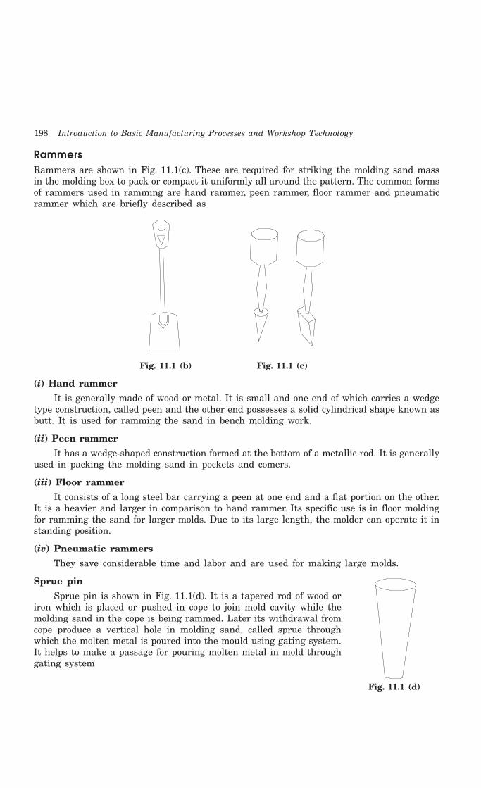
198 Introduction to Basic Manufacturing Processes and Workshop Technology
RammersRammers are shown in Fig. 11.1(c). These are required for striking the molding sand massin the molding box to pack or compact it uniformly all around the pattern. The common formsof rammers used in ramming are hand rammer, peen rammer, floor rammer and pneumaticrammer which are briefly described as
Fig. 11.1 (b) Fig. 11.1 (c)
(i) Hand rammer
It is generally made of wood or metal. It is small and one end of which carries a wedgetype construction, called peen and the other end possesses a solid cylindrical shape known asbutt. It is used for ramming the sand in bench molding work.
(ii) Peen rammer
It has a wedge-shaped construction formed at the bottom of a metallic rod. It is generallyused in packing the molding sand in pockets and comers.
(iii) Floor rammer
It consists of a long steel bar carrying a peen at one end and a flat portion on the other.It is a heavier and larger in comparison to hand rammer. Its specific use is in floor moldingfor ramming the sand for larger molds. Due to its large length, the molder can operate it instanding position.
(iv) Pneumatic rammers
They save considerable time and labor and are used for making large molds.
Sprue pin
Sprue pin is shown in Fig. 11.1(d). It is a tapered rod of wood oriron which is placed or pushed in cope to join mold cavity while themolding sand in the cope is being rammed. Later its withdrawal fromcope produce a vertical hole in molding sand, called sprue throughwhich the molten metal is poured into the mould using gating system.It helps to make a passage for pouring molten metal in mold throughgating system
Fig. 11.1 (d)

Foundry Tools and Equipments 199
Strike off bar
Strike off bar (Fig. 11.1(e)) is a flat bar having straight edge and is made of wood or iron.It is used to strike off or remove the excess sand from the top of a molding box aftercompletion of ramming thereby making its surface plane and smooth. Its one edge is madebeveled and the other end is kept perfectly smooth and plane.
Fig. 11.1 (e)
Mallet
Mallet is similar to a wooden hammer and is generally as used in carpentry or sheetmetal shops. In molding shop, it is used for driving the draw spike into the pattern and thenrapping it for separation from the mould surfaces so that pattern can be easily withdrawnleaving the mold cavity without damaging the mold surfaces.
Draw spike
Draw spike is shown Fig. 11.1(f). It is a tapered steel rod having a loop or ring at its oneend and a sharp point at the other. It may have screw threads on the end to engage metalpattern for it withdrawal from the mold. It is used for driven into pattern which is embeddedin the molding sand and raps the pattern to get separated from the pattern and finally drawsout it from the mold cavity.
Fig. 11.1 (f) Fig. 11.1 (g)
Vent rod
Vent rod is shown in Fig. 11.1(g). It is a thin spiked steel rod or wire carrying a pointededge at one end and a wooden handle or a bent loop at the other. After ramming and strikingoff the excess sand it is utilized to pierce series of small holes in the molding sand in the copeportion. The series of pierced small holes are called vents holes which allow the exit or escapeof steam and gases during pouring mold and solidifying of the molten metal for getting asound casting.
Lifters
Lifters are shown in Fig. 11.1(h, i, j and k). They are also known as cleaners or finishingtool which are made of thin sections of steel of various length and width with one end bent

200 Introduction to Basic Manufacturing Processes and Workshop Technology
at right angle. They are used for cleaning, repairing and finishing the bottom and sides ofdeep and narrow openings in mold cavity after withdrawal of pattern. They are also used forremoving loose sand from mold cavity.
Fig. 11.1 (h) Fig. 11.1 (i)
Fig. 11.1 (j) Fig. 11.1 (k)
Trowels
Trowels are shown in Fig. 11.1(l, m and n). They are utilized for finishing flat surfaces andjoints and partings lines of the mold. They consist of metal blade made of iron and are equippedwith a wooden handle. The common metal blade shapes of trowels may be pointed or contouredor rectangular oriented. The trowels are basically employed for smoothing or slicking thesurfaces of molds. They may also be used to cut in-gates and repair the mold surfaces.
Fig. 11.1 (l) Fig. 11.1 (m)
Fig. 11.1 (n)
Slicks
Slicks are shown in Fig. 11.1(o, p, q, and r). They are also recognized as small doubleended mold finishing tool which are generally used for repairing and finishing the moldsurfaces and their edges after withdrawal of the pattern. The commonly used slicks are of thetypes of heart and leaf, square and heart, spoon and bead and heart and spoon. Thenomenclatures of the slicks are largely due to their shapes.

Foundry Tools and Equipments 201
Fig. 11.1 (o) Fig. 11.1 (p)
Fig. 11.1 (q) Fig. 11.1 (r)
Smoothers
Smothers are shown in Fig. 11.1(s and t). According to their use and shape they aregiven different names. They are also known as finishing tools which are commonly used forrepairing and finishing flat and round surfaces, round or square corners and edges of molds.
Fig. 11.1 (s) Fig. 11.1 (t)
Swab
Swab is shown in Fig. 11.1(u). It is a small hemp fiber brush used formoistening the edges of sand mould, which are in contact with the patternsurface before withdrawing the pattern. It is used for sweeping away themolding sand from the mold surface and pattern. It is also used for coatingthe liquid blacking on the mold faces in dry sand molds.
Spirit level
Spirit level is used by molder to check whether the sand bed or molding box is horizontalor not.
Gate cutter
Gate cutter (Fig. 11.1(v)) is a small shaped piece of sheet metal commonly used to cutrunners and feeding gates for connecting sprue hole with the mold cavity.
Fig. 11.1 (v)
Gaggers
Gaggers are pieces of wires or rods bent at one or both ends which are used for reinforcingthe downward projecting sand mass in the cope are known as gaggers. They support hanging
Fig. 11.1 (u)
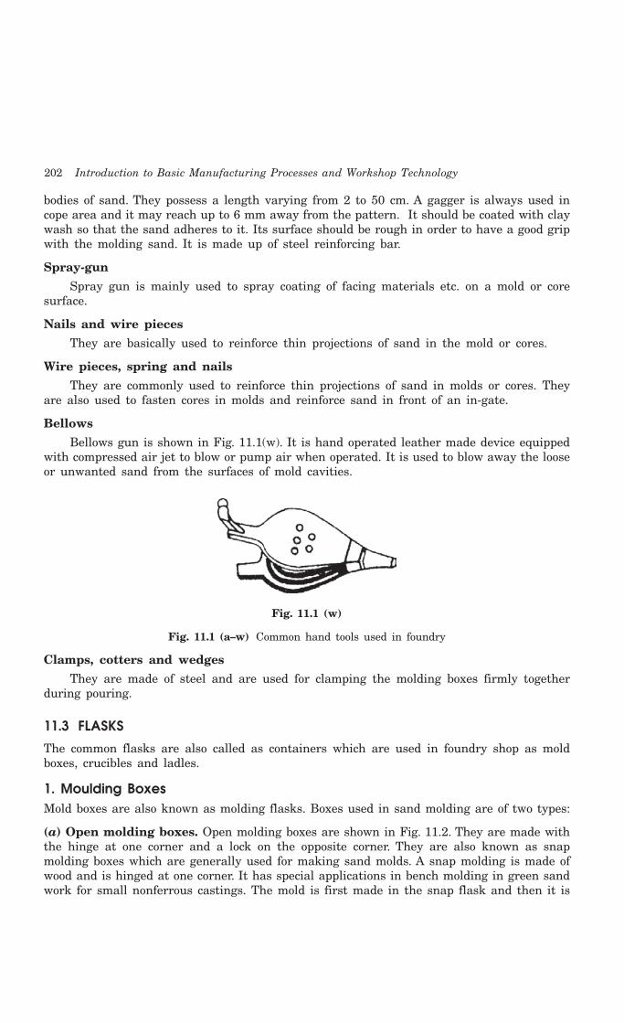
202 Introduction to Basic Manufacturing Processes and Workshop Technology
bodies of sand. They possess a length varying from 2 to 50 cm. A gagger is always used incope area and it may reach up to 6 mm away from the pattern. It should be coated with claywash so that the sand adheres to it. Its surface should be rough in order to have a good gripwith the molding sand. It is made up of steel reinforcing bar.
Spray-gun
Spray gun is mainly used to spray coating of facing materials etc. on a mold or coresurface.
Nails and wire pieces
They are basically used to reinforce thin projections of sand in the mold or cores.
Wire pieces, spring and nails
They are commonly used to reinforce thin projections of sand in molds or cores. Theyare also used to fasten cores in molds and reinforce sand in front of an in-gate.
Bellows
Bellows gun is shown in Fig. 11.1(w). It is hand operated leather made device equippedwith compressed air jet to blow or pump air when operated. It is used to blow away the looseor unwanted sand from the surfaces of mold cavities.
Fig. 11.1 (w)
Fig. 11.1 (a–w) Common hand tools used in foundry
Clamps, cotters and wedges
They are made of steel and are used for clamping the molding boxes firmly togetherduring pouring.
11.3 FLASKS
The common flasks are also called as containers which are used in foundry shop as moldboxes, crucibles and ladles.
1. Moulding BoxesMold boxes are also known as molding flasks. Boxes used in sand molding are of two types:
(a) Open molding boxes. Open molding boxes are shown in Fig. 11.2. They are made withthe hinge at one corner and a lock on the opposite corner. They are also known as snapmolding boxes which are generally used for making sand molds. A snap molding is made ofwood and is hinged at one corner. It has special applications in bench molding in green sandwork for small nonferrous castings. The mold is first made in the snap flask and then it is

Foundry Tools and Equipments 203
removed and replaced by a steel jacket. Thus, a number of molds can be prepared using thesame set of boxes. As an alternative to the wooden snap boxes the cast-aluminum taperedclosed boxes are finding favor in modern foundries. They carry a tapered inside surface whichis accurately ground and finished. A solid structure of this box gives more rigidity andstrength than the open type. These boxes are also removed after assembling the mould.Large molding boxes are equipped with reinforcing cross bars and ribs to hold the heavy massof sand and support gaggers. The size, material and construction of the molding box dependupon the size of the casting.
Hinge
Fig. 11.2 Open molding box
(b) Closed molding boxes. Closed molding boxesare shown in Fig. 11.3 which may be made of wood,cast-iron or steel and consist of two or more parts.The lower part is called the drag, the upper part thecope and all the intermediate parts, if used, cheeks.All the parts are individually equipped with suitablemeans for clamping arrangements during pouring.Wooden Boxes are generally used in green-sandmolding. Dry sand moulds always require metallicboxes because they are heated for drying. Large andheavy boxes are made from cast iron or steel andcarry handles and grips as they are manipulated bycranes or hoists, etc. Closed metallic molding boxesmay be called as a closed rectangular molding box(Fig. 11.3) or a closed round molding box (Fig. 11.4).
2. CrucibleCrucibles are made from graphite or steel shell lined with suitable refractory material likefire clay. They are commonly named as metal melting pots. The raw material or charge isbroken into small pieces and placed in them. They are then placed in pit furnaces which arecoke-fired. In oil- fired tilting furnaces, they form an integral part of the furnace itself andthe charge is put into them while they are in position. After melting of metals in crucibles,they are taken out and received in crucible handle. Pouring of molten is generally donedirectly by them instead of transferring the molten metal to ladles. But in the case of an oil-fired furnace, the molten metal is first received in a ladle and then poured into the molds.
Cope
Drag
Lugs
Fig. 11.3 Closed rectangular molding box

204 Introduction to Basic Manufacturing Processes and Workshop Technology
Fig. 11.4 Closed round molding box
3. LadleIt is similar in shape to the crucible which is also made from graphite or steel shell lined withsuitable refractory material like fire clay. It is commonly used to receive molten metal fromthe melting furnace and pour the same into the mold cavity. Its size is designated by itscapacity. Small hand shank ladles are used by a single foundry personal and are provided withonly one handle. It may be available in different capacities up to 20 kg. Medium and largesize ladles are provided with handles on both sides to be handled by two foundry personals.They are available in various sizes with their capacity varying from 30 kg to 150 kg. Extremelylarge sizes, with capacities ranging from 250 kg to 1000 kg, are found in crane ladles. Gearedcrane ladles can hold even more than 1000 kg of molten metal. The handling of ladles canbe mechanized for good pouring control and ensuring better safety for foundry personalsworkers. All the ladles consist of an outer casing made of steel or plate bent in proper shapeand then welded. Inside this casing, a refractory lining is provided. At its top, the casing isshaped to have a controlled and well directed flow of molten metal. They are commonly usedto transport molten metal from furnace to mold
11.4 POWER OPERATED EQUIPMENTS
Power operated foundry equipments generally used in foundries are different types of moldingmachines and sand slingers, core making, core baking equipment, power riddles, mechanicalconveyors, sand mixers, material handling equipment and sand aerators etc. Few commonlyused types of such equipments are discussed as under.
11.4.1 Moulding MachinesMolding machine acts as a device by means of a large number of co-related parts andmechanisms, transmits and directs various forces and motions in required directions so as tohelp the preparation of a sand mould. The major functions of molding machines involvesramming of molding sand, rolling over or inverting the mould, rapping the pattern andwithdrawing the pattern from the mould. Most of the molding machines perform a combinationof two or more of functions. However, ramming of sand is the basic function of most of thesemachines. Use of molding machine is advisable when large number of repetitive castings isto be produced as hand molding may be tedious, time consuming, laborious and expensivecomparatively.

Foundry Tools and Equipments 205
11.4.2 Classification of Moulding MachinesThe large variety of molding machines that are available in different designs which can beclassified as squeezer machine, jolt machine, jolt-squeezer machine, slinging machines, patterndraw machines and roll over machines. These varieties of machines are discussed as under.
11.4.2.1 Squeezer machine
These machines may be hand operated or power operated. The pattern is placed over themachine table, followed by the molding box. In hand-operated machines, the platen is liftedby hand operated mechanism. In power machines, it is lifted by the air pressure on a pistonin the cylinder in the same way as in jolt machine. The table is raised gradually. The sandin the molding box is squeezed between plate and the upward rising table thus enabling auniform pressing of sand in the molding box. The main advantage of power operated machinesin comparison hand operated machines is that more pressure can be applied in power operated.
11.4.2.2 Jolt machine
This machine is also known as jar machine which comprises of air operated piston andcylinder. The air is allowed to enter from the bottom side of the cylinder and acts on thebottom face of the piston to raise it up. The platen or table of the machine is attached at thetop of the piston which carries the pattern and molding box with sand filled in it. The upwardmovement of piston raises the table to a certain height and the air below the piston issuddenly released, resulting in uniform packing of sand around the pattern in the moldingbox. This process is repeated several times rapidly. This operation is known as jolting technique.
11.4.2.3 Jolt-squeezer machine
It uses the principle of both jolt and squeezer machines in which complete mould isprepared. The cope, match plate and drag are assembled on the machine table in a reverseposition, that is, the drag on the top and the cope below. Initially the drag is filled with sandfollowed by ramming by the jolting action of the table. After leveling off the sand on the uppersurface, the assembly is turned upside down and placed over a bottom board placed on thetable. Next, the cope is filled up with sand and is rammed by squeezing between the overheadplate and the machine table. The overhead plate is then swung aside and sand on the topleveled off, cope is next removed and the drag is vibrated by air vibrator. This is followed byremoval of match plate and closing of two halves of the mold for pouring the molten metal.This machine is used to overcome the drawbacks of both squeeze and jolt principles oframming molding sand.
11.4.2.4 Slinging machines
These machines are also known as sand slingers and are used for filling and uniformramming of molding sand in molds. In the slinging operations, the consolidation and rammingare obtained by impact of sand which falls at a very high velocity on pattern. These machinesare generally preferred for quick preparation of large sand moulds. These machines can alsobe used in combination with other devices such as, roll over machines and pattern drawmachines for reducing manual operations to minimum. These machines can be stationary andportable types. Stationary machines are used for mass production in bigger foundries whereasportable type machines are mounted on wheels and travel in the foundry shop on a wellplanned fixed path. A typical sand slinger consists of a heavy base, a bin or hopper to carrysand, a bucket elevator to which are attached a number of buckets and a swinging arm which
206 Introduction to Basic Manufacturing Processes and Workshop Technology
carries a belt conveyor and the sand impeller head. Well prepared sand is filed in a binthrough the bottom of which it is fed to the elevator buckets. These buckets discharge themolding sand to the belt conveyor which conveys the same to the impeller head. This headcan be moved at any location on the mold by swinging the arm. The head revolves at a veryhigh speed and, in doing so, throws stream of molding sand into the molding box at a highvelocity. This process is known as slinging. The force of sand ejection and striking into themolding box compel the sand gets packed in the box flask uniformly. This way the satisfactoryramming is automatically get competed on the mold. It is a very useful machine in largefoundries.
11.4.2.5 Pattern draw machines
These machines enable easy withdrawal of patterns from the molds. They can be of thekind of stripping plate type and pin lift or push off type. Stripping plate type of pattern drawmachines consists of a stationary platen or table on which is mounted a stripping plate whichcarries a hole in it. The size and shape of this hole is such that it fits accurately around thepattern. The pattern is secured to a pattern plate and the latter to the supporting ram. Thepattern is drawn through the stripping plate either by raising the stripping plate and themould up and keeping the pattern stationary or by keeping the stripping plate and mouldstationary and moving the pattern supporting ram downwards along with the pattern andpattern plate. A suitable mechanism can be incorporated in the machine for these movements.
11.4.2.6 Roll-over machine
This machine comprises of a rigid frame carrying two vertical supports on its two sideshaving bearing supports of trunnions on which the roll-over frame of the machine is mounted.The pattern is mounted on a plate which is secured to the roll-over frame. The platen of themachine can be moved up and down. For preparation of the mould, the roll-over frame isclamped in position with the pattern facing upward. Molding box is placed over the patternplate and clamped properly. Molding sand is then filled in it and rammed by hand and theextra molding sand is struck off and molding board placed over the box and clamped to it.After that the roll-over frame is unclamped and rolled over through 180° to suspend the boxbelow the frame. The platen is then lifted up to butt against the suspending box. The box isunclamped from the pattern plate to rest over the platen which is brought down leaving thepattern attached to the plate. The prepared mold is now lowered. The frame is then againrolled over to the original position for ramming another flask. Other mechanisms are alwaysincorporated to enable the above rolling over and platen motion. Some roll-over machinesmay carry a pneumatic mechanism for rolling over. There are others mechanism also whichincorporate a jolting table for ramming the sand and an air operated rocking arm to facilitaterolling over. Some machines incorporate a mechanically or pneumatically operated squeezingmechanism for sand ramming in addition to the air operated rolling over mechanism. All suchmachines are frequently referred to as combination machines to carry out the molding tasksautomatically.
11.5 QUESTIONS1. How do you classify the different tools and equipment used in foundries?
2. Name the different tools used in hand molding stating their use.
3. Sketch and describe the different types of molding boxes you know.
4. What are ladles and crucibles? How do they differ from each other?

Foundry Tools and Equipments 207
5. Describe the working principles and uses of different molding machines.
6. Describe, with the help of sketches, how a mould is rammed on a diaphragm moldingmachine.
7. What is a molding machine? What main functions does it perform?
8. Describe the principle of working of different pattern draw machines.
9. Describe the principle of working of a rollover machine.
10. What is sand slinger and how does it differ from other molding machines?
208 Introduction to Basic Manufacturing Processes and Workshop Technology
208
MOLD AND CORE MAKING
12.1 INTRODUCTION
A suitable and workable material possessing high refractoriness in nature can be used formould making. Thus, the mold making material can be metallic or non-metallic. For metalliccategory, the common materials are cast iron, mild steel and alloy steels. In the non-metallicgroup molding sands, plaster of paris, graphite, silicon carbide and ceramics are included. But,out of all, the molding sand is the most common utilized non-metallic molding materialbecause of its certain inherent properties namely refractoriness, chemical and thermal stabilityat higher temperature, high permeability and workability along with good strength. Moreover,it is also highly cheap and easily available. This chapter discusses molding and core sand, theconstituents, properties, testing and conditioning of molding and core sands, procedure formaking molds and cores, mold and core terminology and different methods of molding.
12.2 MOLDING SAND
The general sources of receiving molding sands are the beds of sea, rivers, lakes, granulularelements of rocks, and deserts. The common sources of molding sands available in India areas follows:
1 Batala sand ( Punjab)
2 Ganges sand (Uttar Pradesh)
3 Oyaria sand (Bihar)
4 Damodar and Barakar sands (Bengal- Bihar Border)
5 Londha sand (Bombay)
6 Gigatamannu sand (Andhra Pradesh) and
7 Avadi and Veeriyambakam sand (Madras)
Molding sands may be of two types namely natural or synthetic. Natural molding sandscontain sufficient binder. Whereas synthetic molding sands are prepared artificially usingbasic sand molding constituents (silica sand in 88-92%, binder 6-12%, water or moisturecontent 3-6%) and other additives in proper proportion by weight with perfect mixing andmulling in suitable equipments.
12CHAPTER

Mold and Core Making 209
12.3 CONSTITUENTS OF MOLDING SAND
The main constituents of molding sand involve silica sand, binder, moisture content and additives.
12.3.1 Silica sandSilica sand in form of granular quarts is the main constituent of molding sand having enoughrefractoriness which can impart strength, stability and permeability to molding and core sand.But along with silica small amounts of iron oxide, alumina, lime stone, magnesia, soda andpotash are present as impurities. The chemical composition of silica sand gives an idea of theimpurities like lime, magnesia, alkalis etc. present. The presence of excessive amounts ofiron oxide, alkali oxides and lime can lower the fusion point to a considerable extent whichis undesirable. The silica sand can be specified according to the size (small, medium and largesilica sand grain) and the shape (angular, sub-angular and rounded).
12.3.1.1 Effect of grain shape and size of silica sandThe shape and size of sand grains has a significant effect on the different properties of
molding and core sands. The shape of the sand grains in the mold or core sand determinesthe possibility of its application in various types of foundry practice. The shape of foundry sandgrains varies from round to angular. Some sands consist almost entirely of grains of oneshape, whereas others have a mixture of various shapes. According to shape, foundry sandsare classified as rounded, sub-angular, angular and compound. Use of angular grains (obtainedduring crushing of rocks hard sand stones) is avoided as these grains have a large surfacearea. Molding sands composed of angular grains will need higher amount of binder andmoisture content for the greater specific surface area of sand grain. However, a higherpercentage of binder is required to bring in the desired strength in the molding sand and coresand. For good molding purposes, a smooth surfaced sand grains are preferred. The smoothsurfaced grain has a higher sinter point, and the smooth surface secures a mixture of greaterpermeability and plasticity while requiring a higher percentage of blind material. Roundedshape silica sand grain sands are best suited for making permeable molding sand. Thesegrains contribute to higher bond strength in comparison to angular grain. However, roundedsilica sand grains sands have higher thermal expandability than angular silica grain sands.Silica sand with rounded silica sand grains gives much better compactability under the sameconditions than the sands with angular silica grains. This is connected with the fact that thesilica sand with rounded grains having the greatest degree of close packing of particles whilesand with angular grains the worst. The green strength increases as the grains become morerounded. On the other hand, the grade of compactability of silica sands with rounded sandgrains is higher, and other, the contact surfaces between the individual grains are greater onrounded grains than on angular grains. As already mentioned above, the compactabilityincreases with rounded grains. The permeability or porosity property of molding sand andcore sand therefore, should increase with rounded grains and decrease with angular grains.Thus the round silica sand grain size greatly influences the properties of molding sand.
The characteristics of sub-angular sand grains lie in between the characteristics of sandgrains of angular and rounded kind. Compound grains are cemented together such that theyfail to get separated when screened through a sieve. They may consist of round, sub-angular,or angular sub-angular sand grains. Compound grains require higher amounts of binder andmoisture content also. These grains are least desirable in sand mixtures because they havea tendency to disintegrate at high temperatures. Moreover the compound grains are cementedtogether and they fail to separate when screened.
210 Introduction to Basic Manufacturing Processes and Workshop Technology
Grain sizes and their distribution in molding sand influence greatly the properties of thesand. The size and shape of the silica sand grains have a large bearing upon its strength andother general characteristics. The sand with wide range of particle size has higher compactabilitythan sand with narrow distribution. The broadening of the size distribution may be doneeither to the fine or the coarse side of the distribution or in both directions simultaneously,and a sand of higher density will result. Broadening to the coarse side has a greater effecton density than broadening the distribution to the fine sand. Wide size distributions favorgreen strength, while narrow grain distributions reduce it. The grain size distribution has asignificant effect on permeability. Silica sand containing finer and a wide range of particlesizes will have low permeability as compared to those containing grains of average finenessbut of the same size i.e. narrow distribution. The compactability is expressed by the greendensity obtained by three ram strokes. Finer the sand, the lower is the compactability andvice versa. This results from the fact that the specific surface increases as the grain sizedecreases. As a result, the number of points of contact per unit of volume increases and thisin turn raises the resistance to compacting. The green strength has a certain tendency,admittedly not very pronounced, towards a maximum with a grain size which correspondsapproximately to the medium grain size. As the silica sand grains become finer, the film ofbentonite becomes thinner, although the percentage of bentonite remains the same. Due toreducing the thickness of binder film, the green strength is reduced. With very coarse grains,however, the number of grains and, therefore, the number of points of contact per unit ofvolume decreases so sharply that the green strength is again reduced. The sands with grainsequal but coarser in size have greater void space and have, therefore greater permeabilitythan the finer silica sands. This is more pronounced if sand grains are equal in size.
12.3.2 BinderIn general, the binders can be either inorganic or organic substance. The inorganic groupincludes clay sodium silicate and port land cement etc. In foundry shop, the clay acts as binderwhich may be Kaolonite, Ball Clay, Fire Clay, Limonite, Fuller’s earth and Bentonite. Bindersincluded in the organic group are dextrin, molasses, cereal binders, linseed oil and resins likephenol formaldehyde, urea formaldehyde etc. Organic binders are mostly used for core making.Among all the above binders, the bentonite variety of clay is the most common. However, thisclay alone can not develop bonds among sand grins without the presence of moisture inmolding sand and core sand.
12.3.3 MoistureThe amount of moisture content in the molding sand varies generally between 2 to 8 percent.This amount is added to the mixture of clay and silica sand for developing bonds. This is theamount of water required to fill the pores between the particles of clay without separatingthem. This amount of water is held rigidly by the clay and is mainly responsible for developingthe strength in the sand. The effect of clay and water decreases permeability with increasingclay and moisture content. The green compressive strength first increases with the increasein clay content, but after a certain value, it starts decreasing.
For increasing the molding sand characteristics some other additional materials besidesbasic constituents are added which are known as additives.
12.3.4 AdditivesAdditives are the materials generally added to the molding and core sand mixture to develop

Mold and Core Making 211
some special property in the sand. Some common used additives for enhancing the propertiesof molding and core sands are discussed as under.
12.3.4.1 Coal dust Coal dust is added mainly for producing a reducing atmosphere during casting. This
reducing atmosphere results in any oxygen in the poles becoming chemically bound so thatit cannot oxidize the metal. It is usually added in the molding sands for making molds forproduction of grey iron and malleable cast iron castings.
12.3.4.2 Corn flourIt belongs to the starch family of carbohydrates and is used to increase the collapsibility
of the molding and core sand. It is completely volatilized by heat in the mould, therebyleaving space between the sand grains. This allows free movement of sand grains, whichfinally gives rise to mould wall movement and decreases the mold expansion and hencedefects in castings. Corn sand if added to molding sand and core sand improves significantlystrength of the mold and core.
12.3.4.3 DextrinDextrin belongs to starch family of carbohydrates that behaves also in a manner similar
to that of the corn flour. It increases dry strength of the molds.
12.3.4.4 Sea coal Sea coal is the fine powdered bituminous coal which positions its place among the pores
of the silica sand grains in molding sand and core sand. When heated, it changes to cokewhich fills the pores and is unaffected by water: Because to this, the sand grains becomerestricted and cannot move into a dense packing pattern. Thus, sea coal reduces the mouldwall movement and the permeability in mold and core sand and hence makes the mold andcore surface clean and smooth.
12.3.4.5 PitchIt is distilled form of soft coal. It can be added from 0.02 % to 2% in mold and core sand.
It enhances hot strengths, surface finish on mold surfaces and behaves exactly in a mannersimilar to that of sea coal.
12.3.4.6 Wood flourThis is a fibrous material mixed with a granular material like sand; its relatively long
thin fibers prevent the sand grains from making contact with one another. It can be addedfrom 0.05 % to 2% in mold and core sand. It volatilizes when heated, thus allowing the sandgrains room to expand. It will increase mould wall movement and decrease expansion defects.It also increases collapsibility of both of mold and core.
12.3.4.7 Silica flourIt is called as pulverized silica and it can be easily added up to 3% which increases the
hot strength and finish on the surfaces of the molds and cores. It also reduces metal penetrationin the walls of the molds and cores.
12.4 KINDS OF MOULDING SAND
Molding sands can also be classified according to their use into number of varieties which aredescribed below.
212 Introduction to Basic Manufacturing Processes and Workshop Technology
12.4.1 Green sandGreen sand is also known as tempered or natural sand which is a just prepared mixture ofsilica sand with 18 to 30 percent clay, having moisture content from 6 to 8%. The clay andwater furnish the bond for green sand. It is fine, soft, light, and porous. Green sand is damp,when squeezed in the hand and it retains the shape and the impression to give to it underpressure. Molds prepared by this sand are not requiring backing and hence are known asgreen sand molds. This sand is easily available and it possesses low cost. It is commonlyemployed for production of ferrous and non-ferrous castings.
12.4.2 Dry sandGreen sand that has been dried or baked in suitable oven after the making mold and cores,is called dry sand. It possesses more strength, rigidity and thermal stability. It is mainlysuitable for larger castings. Mold prepared in this sand are known as dry sand molds.
12.4.3 Loam sandLoam is mixture of sand and clay with water to a thin plastic paste. Loam sand possesses highclay as much as 30-50% and 18% water. Patterns are not used for loam molding and shapeis given to mold by sweeps. This is particularly employed for loam molding used for large greyiron castings.
12.4.4 Facing sandFacing sand is just prepared and forms the face of the mould. It is directly next to the surfaceof the pattern and it comes into contact molten metal when the mould is poured. Initialcoating around the pattern and hence for mold surface is given by this sand. This sand issubjected severest conditions and must possess, therefore, high strength refractoriness. It ismade of silica sand and clay, without the use of used sand. Different forms of carbon are usedto prevent the metal burning into the sand. A facing sand mixture for green sand of cast ironmay consist of 25% fresh and specially prepared and 5% sea coal. They are sometimes mixedwith 6-15 times as much fine molding sand to make facings. The layer of facing sand in a moldusually ranges from 22-28 mm. From 10 to 15% of the whole amount of molding sand is thefacing sand.
12.4.5 Backing sandBacking sand or floor sand is used to back up the facing sand and is used to fill the wholevolume of the molding flask. Used molding sand is mainly employed for this purpose. Thebacking sand is sometimes called black sand because that old, repeatedly used molding sandis black in color due to addition of coal dust and burning on coming in contact with the moltenmetal.
12.4.6 System sandIn mechanized foundries where machine molding is employed. A so-called system sand is usedto fill the whole molding flask. In mechanical sand preparation and handling units, no facingsand is used. The used sand is cleaned and re-activated by the addition of water and specialadditives. This is known as system sand. Since the whole mold is made of this system sand,the properties such as strength, permeability and refractoriness of the molding sand must behigher than those of backing sand.
Mold and Core Making 213
12.4.7 Parting sandParting sand without binder and moisture is used to keep the green sand not to stick to thepattern and also to allow the sand on the parting surface the cope and drag to separatewithout clinging. This is clean clay-free silica sand which serves the same purpose as partingdust.
12.4.8 Core sandCore sand is used for making cores and it is sometimes also known as oil sand. This is highlyrich silica sand mixed with oil binders such as core oil which composed of linseed oil, resin,light mineral oil and other bind materials. Pitch or flours and water may also be used in largecores for the sake of economy.
12.5 PROPERTIES OF MOULDING SAND
The basic properties required in molding sand and core sand are described as under.
12.5.1 RefractorinessRefractoriness is defined as the ability of molding sand to withstand high temperatureswithout breaking down or fusing thus facilitating to get sound casting. It is a highly importantcharacteristic of molding sands. Refractoriness can only be increased to a limited extent.Molding sand with poor refractoriness may burn on to the casting surface and no smoothcasting surface can be obtained. The degree of refractoriness depends on the SiO2 i.e. quartzcontent, and the shape and grain size of the particle. The higher the SiO2 content and therougher the grain volumetric composition the higher is the refractoriness of the molding sandand core sand. Refractoriness is measured by the sinter point of the sand rather than its-melting point.
12.5.2 PermeabilityIt is also termed as porosity of the molding sand in order to allow the escape of any air, gasesor moisture present or generated in the mould when the molten metal is poured into it. Allthese gaseous generated during pouring and solidification process must escape otherwise thecasting becomes defective. Permeability is a function of grain size, grain shape, and moistureand clay contents in the molding sand. The extent of ramming of the sand directly affects thepermeability of the mould. Permeability of mold can be further increased by venting usingvent rods
12.5.3 CohesivenessIt is property of molding sand by virtue which the sand grain particles interact and attracteach other within the molding sand. Thus, the binding capability of the molding sand getsenhanced to increase the green, dry and hot strength property of molding and core sand.
12.5.4 Green strengthThe green sand after water has been mixed into it, must have sufficient strength and toughnessto permit the making and handling of the mould. For this, the sand grains must be adhesive,i.e. thev must be capable of attaching themselves to another body and. therefore, and sandgrains having high adhesiveness will cling to the sides of the molding box. Also, the sandgrains must have the property known as cohesiveness i.e. ability of the sand grains to stick
214 Introduction to Basic Manufacturing Processes and Workshop Technology
to one another. By virtue of this property, the pattern can be taken out from the mouldwithout breaking the mould and also the erosion of mould wall surfaces does not occur duringthe flow of molten metal. The green strength also depends upon the grain shape and size,amount and type of clay and the moisture content.
12.5.5 Dry strengthAs soon as the molten metal is poured into the mould, the moisture in the sand layer adjacentto the hot metal gets evaporated and this dry sand layer must have sufficient strength to itsshape in order to avoid erosion of mould wall during the flow of molten metal. The drystrength also prevents the enlargement of mould cavity cause by the metallostatic pressureof the liquid metal.
12.5.6 Flowability or plasticityIt is the ability of the sand to get compacted and behave like a fluid. It will flow uniformlyto all portions of pattern when rammed and distribute the ramming pressure evenly allaround in all directions. Generally sand particles resist moving around corners or projections.In general, flowability increases with decrease in green strength, an, decrease in grain size.The flowability also varies with moisture and clay content.
12.5.7 AdhesivenessIt is property of molding sand to get stick or adhere with foreign material such sticking ofmolding sand with inner wall of molding box
12.5.8 CollapsibilityAfter the molten metal in the mould gets solidified, the sand mould must be collapsible sothat free contraction of the metal occurs and this would naturally avoid the tearing orcracking of the contracting metal. In absence of this property the contraction of the metal ishindered by the mold and thus results in tears and cracks in the casting. This property ishighly desired in cores
12.5.9 Miscellaneous propertiesIn addition to above requirements, the molding sand should not stick to the casting and
should not chemically react with the metal. Molding sand should be cheap and easily available.It should be reusable for economic reasons. Its coefficients of expansion should be sufficientlylow.
12.6 SAND TESTING
Molding sand and core sand depend upon shape, size composition and distribution of sandgrains, amount of clay, moisture and additives. The increase in demand for good surface finishand higher accuracy in castings necessitates certainty in the quality of mold and core sands.Sand testing often allows the use of less expensive local sands. It also ensures reliable sandmixing and enables a utilization of the inherent properties of molding sand. Sand testing ondelivery will immediately detect any variation from the standard quality, and adjustment ofthe sand mixture to specific requirements so that the casting defects can be minimized. Itallows the choice of sand mixtures to give a desired surface finish. Thus sand testing is oneof the dominating factors in foundry and pays for itself by obtaining lower per unit cost and

Mold and Core Making 215
increased production resulting from sound castings. Generally the following tests are performedto judge the molding and casting characteristics of foundry sands:
1. Moisture content Test
2. Clay content Test
3. Chemical composition of sand
4. Grain shape and surface texture of sand.
5. Grain size distribution of sand
6. Specific surface of sand grains
7. Water absorption capacity of sand
8. Refractoriness of sand
9. Strength Test
10. Permeability Test
11. Flowability Test
12. Shatter index Test
13. Mould hardness Test.
Some of the important sand tests are discussed as under.
12.6.1 Moisture Content TestThe moisture content of the molding sand mixture may determined by drying a weighedamount of 20 to 50 grams of molding sand to a constant temperature up to 100°C in a ovenfor about one hour. It is then cooled to a room temperature and then reweighing the moldingsand. The moisture content in molding sand is thus evaporated. The loss in weight of moldingsand due to loss of moisture, gives the amount of moisture which can be expressed as apercentage of the original sand sample. The percentage of moisture content in the moldingsand can also be determined in fact more speedily by an instrument known as a speedymoisture teller. This instrument is based on the principle that when water and calciumcarbide react, they form acetylene gas which can be measured and this will be directlyproportional to the moisture content. This instrument is provided with a pressure gaugecalibrated to read directly the percentage of moisture present in the molding sand. Somemoisture testing instruments are based on principle that the electrical conductivity of sandvaries with moisture content in it.
12.6.2 Clay Content TestThe amount of clay is determined by carrying out the clay content test in which clay inmolding sand of 50 grams is defined as particles which when suspended in water, fail to settleat the rate of one inch per min. Clay consists of particles less than 20 micron, per 0.0008 inchin dia.
12.6.3 Grain Fineness TestFor carry out grain fineness test a sample of dry silica sand weighing 50 gms free from clayis placed on a top most sieve bearing U.S. series equivalent number 6. A set of eleven sieveshaving U.S. Bureau of standard meshes 6, 12, 20, 30, 40, 50, 70, 100, 140, 200 and 270 aremounted on a mechanical shaker (Fig. 12.1). The series are placed in order of fineness from

216 Introduction to Basic Manufacturing Processes and Workshop Technology
top to bottom. The free silica sand sample is shaked in a mechanical shaker for about 15minutes. After this weight of sand retained in each sieve is obtained sand and the retainedsand in each sieve is multiplied by 2 which gives % of weight retained by each sieve. Thesame is further multiplied by a multiplying factor and total product is obtained. It is thendivided by total % sand retained by different sieves which will give G.F.N.
Adjusting K nob
C lam ping strip
S ide flex ib le bar
Se t o f s ieve
Spring
Bum per
Toggle sw itch
Indica to r lam p
Pane l
Levellingscrew
Timer
Base
Fig. 12.1 Grain fitness testing mecanical shaker
12.6.4 Refractoriness TestThe refractoriness of the molding sand is judged by heating the American Foundry Society(A.F.S) standard sand specimen to very high temperatures ranges depending upon the typeof sand. The heated sand test pieces are cooled to room temperature and examined under amicroscope for surface characteristics or by scratching it with a steel needle. If the silica sandgrains remain sharply defined and easily give way to the needle. Sintering has not yet setin. In the actual experiment the sand specimen in a porcelain boat is p1aced into an e1ectricfurnace. It is usual practice to start the test from l000°C and raise the temperature in stepsof 100°C to 1300°C and in steps of 50° above 1300°C till sintering of the silica sand grains takesplace. At each temperature level, it is kept for at least three minutes and then taken out fromthe oven for examination under a microscope for evaluating surface characteristics or byscratching it with a steel needle.
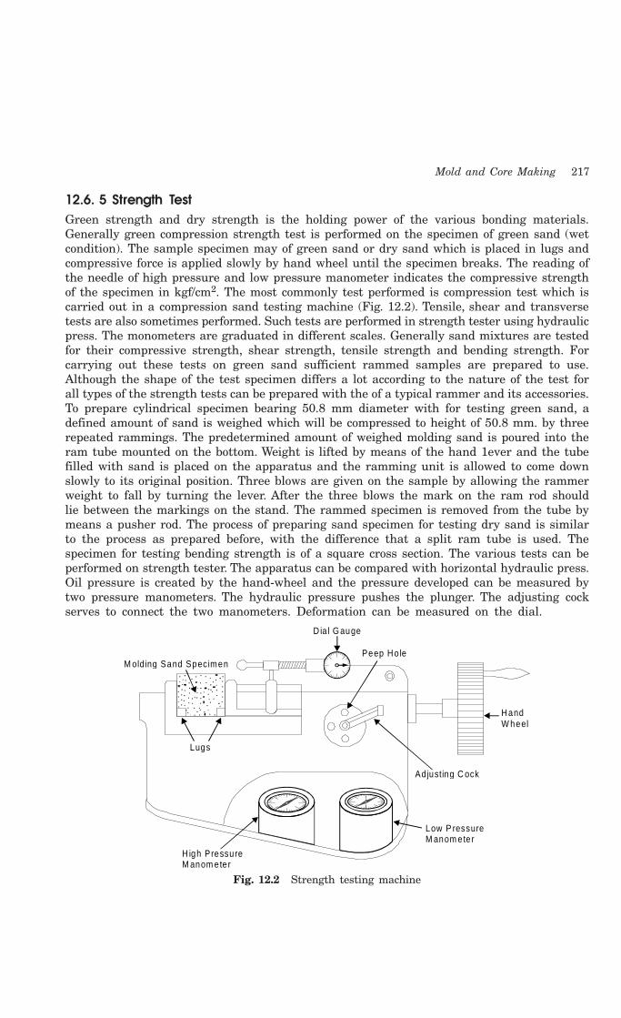
Mold and Core Making 217
12.6. 5 Strength TestGreen strength and dry strength is the holding power of the various bonding materials.Generally green compression strength test is performed on the specimen of green sand (wetcondition). The sample specimen may of green sand or dry sand which is placed in lugs andcompressive force is applied slowly by hand wheel until the specimen breaks. The reading ofthe needle of high pressure and low pressure manometer indicates the compressive strengthof the specimen in kgf/cm2. The most commonly test performed is compression test which iscarried out in a compression sand testing machine (Fig. 12.2). Tensile, shear and transversetests are also sometimes performed. Such tests are performed in strength tester using hydraulicpress. The monometers are graduated in different scales. Generally sand mixtures are testedfor their compressive strength, shear strength, tensile strength and bending strength. Forcarrying out these tests on green sand sufficient rammed samples are prepared to use.Although the shape of the test specimen differs a lot according to the nature of the test forall types of the strength tests can be prepared with the of a typical rammer and its accessories.To prepare cylindrical specimen bearing 50.8 mm diameter with for testing green sand, adefined amount of sand is weighed which will be compressed to height of 50.8 mm. by threerepeated rammings. The predetermined amount of weighed molding sand is poured into theram tube mounted on the bottom. Weight is lifted by means of the hand 1ever and the tubefilled with sand is placed on the apparatus and the ramming unit is allowed to come downslowly to its original position. Three blows are given on the sample by allowing the rammerweight to fall by turning the lever. After the three blows the mark on the ram rod shouldlie between the markings on the stand. The rammed specimen is removed from the tube bymeans a pusher rod. The process of preparing sand specimen for testing dry sand is similarto the process as prepared before, with the difference that a split ram tube is used. Thespecimen for testing bending strength is of a square cross section. The various tests can beperformed on strength tester. The apparatus can be compared with horizontal hydraulic press.Oil pressure is created by the hand-wheel and the pressure developed can be measured bytwo pressure manometers. The hydraulic pressure pushes the plunger. The adjusting cockserves to connect the two manometers. Deformation can be measured on the dial.
M olding Sand Specimen
D ia l G auge
Peep Ho le
Lugs
H igh Pressure M anom eter
Hand W heel
Ad justing C ock
Low P ressure M anom eter
Fig. 12.2 Strength testing machine
218 Introduction to Basic Manufacturing Processes and Workshop Technology
The compression strength of the molding sand is determined by placing standard specimenat specified location and the load is applied on the standard sand specimen to compress it byuniform increasing load using rotating the hand wheel of compression strength testing set-up. As soon as the sand specimen fractures for break, the compression strength is measuredby the manometer. Also, other strength tests can be conducted by adopting special types ofspecimen holding accessories.
12.6.6 Permeability TestInitially a predetermined amount of molding sand is being kept in a standard cylindrical tube,and the molding sand is compressed using slightly tapered standard ram till the cylindricalstandard sand specimen having 50.8mm diameter with 50.8 mm height is made and it is thenextracted. This specimen is used for testing the permeability or porosity of molding and thecore sand. This test is applied for testing porosity of the standard sand specimen. The testis performed in a permeability meter consisting of the balanced tank, water tank, nozzle,adjusting lever, nose piece for fixing sand specimen and a manometer. A typical permeabilitymeter is shown in Fig. 12.3 which permits to read the permeability directly. The permeabilitytest apparatus comprises of a cylinder and another concentric cylinder inside the outercylinder and the space between the two concentric cylinders is filled with water. A bell havinga diameter larger than that of the inner cylinder but smaller than that of outer cylinder, restson the surface of water. Standard sand specimen of 5.08 mm diameter and 50.8 mm heighttogether with ram tube is placed on the tapered nose piece of the permeability meter. Thebell is allowed to sink under its own weight by the help of multi-position cock. In this waythe air of the bell streams through the nozzle of nosepiece and the permeability is directlymeasured.
Permeability is volume of air (in cm3) passing through a sand specimen of 1 cm2 cross-sectional area and 1 cm height, at a pressure difference of 1 gm/cm2 in one minute. Ingeneral, permeability is expressed as a number and can be calculated from the relation
P = vh/patWhere, P = permeability
v = volume of air passing through the specimen in c.c.h = height of specimen in cmp = pressure of air in gm/cm2
a = cross-sectional area of the specimen in cm2
t = time in minutes.
For A.F S. standard permeability meter, 2000 cc of air is passed through a sand specimen(5.08 cm in height and 20.268 sq. cm. in cross-sectional area) at a pressure of 10 gms/cm2 andthe total time measured is 10 seconds = 1/6 min. Then the permeability is calculated usingthe relationship as given as under.
P = (2000 × 5.08) / (10 × 20.268 × (1/6)) = 300.66 App.
12.6.7 Flowability TestFlowability of the molding and core sand usually determined by the movement of the rammerplunger between the fourth and fifth drops and is indicated in percentages. This reading candirectly be taken on the dial of the flow indicator. Then the stem of this indicator rests againtop of the plunger of the rammer and it records the actual movement of the plunger betweenthe fourth and fifth drops.

Mold and Core Making 219
Balanced tank
Water tank
Nozzle adjusting lever
Nose p iece fo r fix ing sand specim en tube
D ia l meter
Ba lanced tank
Specim en tube
M olding sandsam ple
Pressure m anom eter
M ercury seal
A ir passage
Variab le nozzle
Fig. 12.3 Permeability meter
12.6.8 Shatter Index TestIn this test, the A.F.S. standard sand specimen is rammed usually by 10 blows and then itis allowed to fall on a half inch mesh sieve from a height of 6 ft. The weight of sand retainedon the sieve is weighed. It is then expressed as percentage of the total weight of the specimenwhich is a measure of the shatter index.
12.6.9 Mould Hardness TestThis test is performed by a mold hardness tester shown in Fig. 12.4. The working of thetester is based on the principle of Brinell hardness testing machine. In an A.F.S. standardhardness tester a half inch diameter steel hemi-spherical ball is loaded with a spring load of980 gm. This ball is made to penetrate into the mold sand or core sand surface. The penetration

220 Introduction to Basic Manufacturing Processes and Workshop Technology
of the ball point into the mould surface is indicated ona dial in thousands of an inch. The dial is calibrated toread the hardness directly i.e. a mould surface whichoffers no resistance to the steel ball would have zerohardness value and a mould which is more rigid and iscapable of completely preventing the steel ball frompenetrating would have a hardness value of 100. Thedial gauge of the hardness tester may provide directreadings
12.7 SAND CONDITIONING
Natural sands are generally not well suited forcasting purposes. On continuous use of molding sand,the clay coating on the sand particles gets thinned outcausing decrease in its strength. Thus proper sandconditioning accomplish uniform distribution of binderaround the sand grains, control moisture content,eliminate foreign particles and aerates the sands.Therefore, there is a need for sand conditioning forachieving better results.
The foreign materials, like nails, gaggers, hard sand lumps and metals from the usedsand are removed. For removing the metal pieces, particularly ferrous pieces, the sand fromthe shake-out station is subjected to magnetic separator, which separates out the iron pieces,nails etc. from the used sand. Next, the sand is screened in riddles which separate out thehard sand lumps etc. These riddles may be manual as well as mechanical. Mechanical riddlesmay be either compressed air operated or electrically operated. But the electrically operatedriddles are faster and can handle large quantities of sand in a short time. The amount of finematerial can be controlled to the maximum possible extent by its removal through exhaustsystems under conditions of shake out.
The sand constituents are then brought atrequired proper proportion and mixedthoroughly. Next, the whole mixture is mulledsuitably till properties are developed. After allthe foreign particles are removed from and thesand is free from the hard lumps etc., properamount of pure sand, clay and required additivesare added to for the loss because of the burned,clay and other corn materials. As the moisturecontent of the returned sand known, it is to betested and after knowing the moisture therequired amount of water is added. Now thesethings are mixed thoroughly in a mixing muller(Fig 12.5).
The main objectives of a mixing muller is to distribute the binders, additives and moistureor water content uniformly all around each sand grain and helps to develop the optimumphysical properties by kneading on the sand grains. Inadequate mulling makes the sand
Plastic S leeve
M etallic S leeve
Need le
D ia l
R ing
Tip
M ou ld Hardness Teste r
Fig. 12.4 Mould harness tester
M olding Sand
Fig. 12.5 Sand mixing muller

Mold and Core Making 221
mixture weak which can only be compensated by adding more binder. Thus the adequatemulling economizes the use of binders. There are two methods of adding clay and waterto sand. In the first method, first water is added to sand follow by clay, while in the othermethod, clay addition is followed water. It has been suggested that the best order ofadding ingredients to clay bonded sand is sand with water followed by the binders. In thisway, the clay is more quickly and uniformly spread on to all the sand grains. An additionaladvantage of this mixing order is that less dust is produced during the mulling operation.The muller usually consists of a cylindrical pan in which two heavy rollers; carrying twoploughs, and roll in a circular path. While the rollers roll, the ploughs scrap the sand fromthe sides and the bottom of the pan and place it in front of For producing a smearingaction in the sand, the rollers are set slightly off the true radius and they move out ofthe rollers can be moved up and down without difficulty mounted on rocker arms. Afterthe mulling is completed sand can be discharged through a door. The mechanical aeratorsare generally used for aerating or separating the sand grains by increasing the flowabilitythrough whirling the sand at a high speed by an impeller towards the inner walls of thecasting. Aerating can also be done by riddling the sand mixture oil on a one fourth inchmesh screen or by spraying the sand over the sand heap by flipping the shovels. Theaeration separates the sand grains and leaves each grain free to flow in the direction oframming with less friction. The final step in sand conditioning is the cooling of sandmixture because of the fact that if the molding sand mixture is hot, it will cause moldingdifficulties.
12.8 STEPS INVOLVED IN MAKING A SAND MOLD
1. Initially a suitable size of molding box for creating suitable wall thickness is selectedfor a two piece pattern. Sufficient care should also be taken in such that sense thatthe molding box must adjust mold cavity, riser and the gating system (sprue, runnerand gates etc.).
2. Next, place the drag portion of the pattern with the parting surface down on thebottom (ram-up) board as shown in Fig. 12.6 (a).
3. The facing sand is then sprinkled carefully all around the pattern so that thepattern does not stick with molding sand during withdrawn of the pattern.
4. The drag is then filled with loose prepared molding sand and ramming of themolding sand is done uniformly in the molding box around the pattern. Fill themolding sand once again and then perform ramming. Repeat the process three fourtimes,
5. The excess amount of sand is then removed using strike off bar to bring moldingsand at the same level of the molding flask height to completes the drag.
6. The drag is then rolled over and the parting sand is sprinkled over on the top ofthe drag [Fig. 12.6(b)].
7. Now the cope pattern is placed on the drag pattern and alignment is done usingdowel pins.
8. Then cope (flask) is placed over the rammed drag and the parting sand is sprinkledall around the cope pattern.

222 Introduction to Basic Manufacturing Processes and Workshop Technology
9. Sprue and riser pins are placed in vertically position at suitable locations usingsupport of molding sand. It will help to form suitable sized cavities for pouringmolten metal etc. [Fig. 12.6 (c)].
10. The gaggers in the cope are set at suitable locations if necessary. They should notbe located too close to the pattern or mold cavity otherwise they may chill thecasting and fill the cope with molding sand and ram uniformly.
11. Strike off the excess sand from the top of the cope.
12. Remove sprue and riser pins and create vent holes in the cope with a vent wire.The basic purpose of vent creating vent holes in cope is to permit the escape ofgases generated during pouring and solidification of the casting.
13. Sprinkle parting sand over the top of the cope surface and roll over the cope on thebottom board.
14. Rap and remove both the cope and drag patterns and repair the mold suitably ifneeded and dressing is applied
15. The gate is then cut connecting the lower base of sprue basin with runner and thenthe mold cavity.
16. Apply mold coating with a swab and bake the mold in case of a dry sand mold.
17. Set the cores in the mold, if needed and close the mold by inverting cope over drag.
18. The cope is then clamped with drag and the mold is ready for pouring,[Fig. 12.6 (d)].
Drag
Aligning P inDrag Pattern
Bottom board
(a )
A ligning P in
Ramm edM ould ing Sand
(b)
Sprue p in
R iser P in
Cope
Lug
Aligningp in
Drag
Sprue
Patte rn
Pouring basin R iser Parting line
M old
Skimbob
G ate(d)(c)
Fig. 12.6 Mold making
Example of making another mold is illustrated through Fig. 12.7
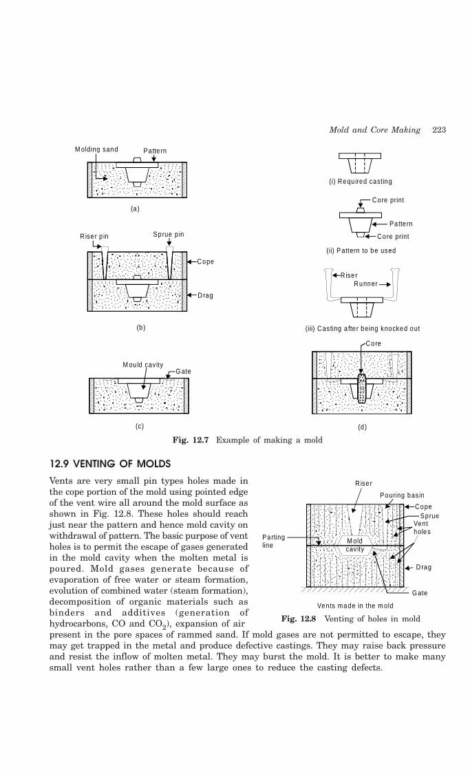
Mold and Core Making 223
Patte rn
(a )
Sprue p inR iser p in
Cope
Drag
(b)
(i) Requ ired casting
Core print
Core print
Pa tte rn
(ii) P attern to be used
R iser Runner
(iii) Casting a fte r being knocked out
Core
M ou ld cavity G ate
(c) (d )
M olding sand
Fig. 12.7 Example of making a mold
12.9 VENTING OF MOLDS
Vents are very small pin types holes made inthe cope portion of the mold using pointed edgeof the vent wire all around the mold surface asshown in Fig. 12.8. These holes should reachjust near the pattern and hence mold cavity onwithdrawal of pattern. The basic purpose of ventholes is to permit the escape of gases generatedin the mold cavity when the molten metal ispoured. Mold gases generate because ofevaporation of free water or steam formation,evolution of combined water (steam formation),decomposition of organic materials such asbinders and additives (generation ofhydrocarbons, CO and CO2), expansion of airpresent in the pore spaces of rammed sand. If mold gases are not permitted to escape, theymay get trapped in the metal and produce defective castings. They may raise back pressureand resist the inflow of molten metal. They may burst the mold. It is better to make manysmall vent holes rather than a few large ones to reduce the casting defects.
Riser
Cope
Ventholes
Drag
G ate
Vents made in the m old
M old cavity
Pouring basin
Sprue
Partingline
Fig. 12.8 Venting of holes in mold
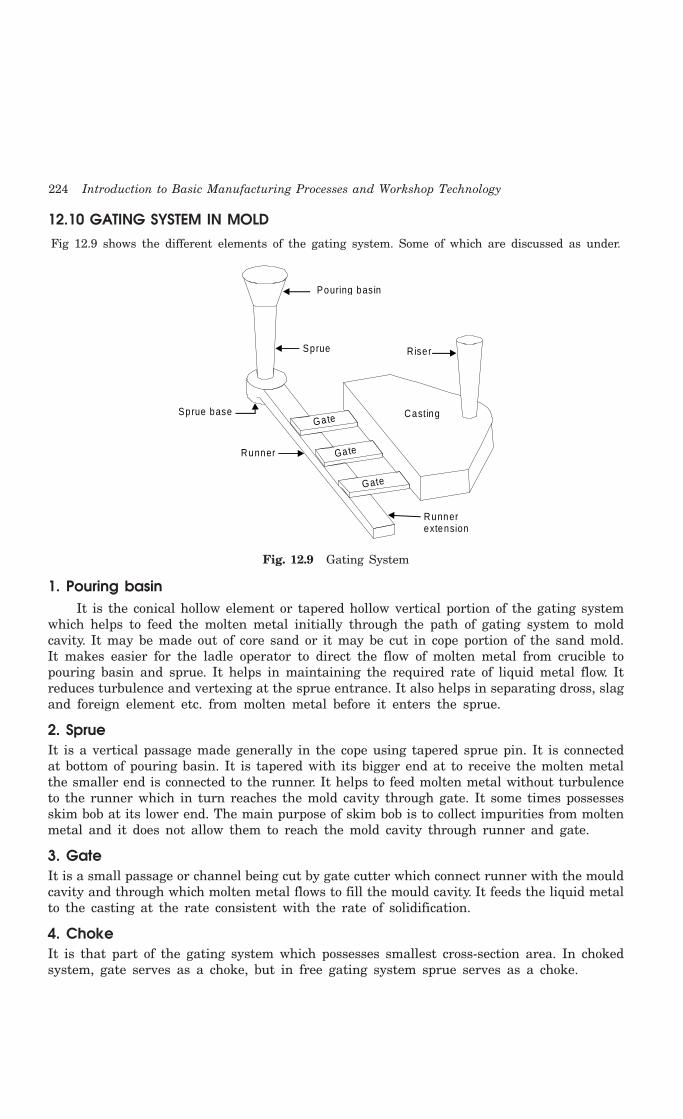
224 Introduction to Basic Manufacturing Processes and Workshop Technology
12.10 GATING SYSTEM IN MOLDFig 12.9 shows the different elements of the gating system. Some of which are discussed as under.
Pouring basin
Sprue R iser
Casting
Runnerextension
Ga te
Ga te
Gate
Sprue base
Runner
Fig. 12.9 Gating System
1. Pouring basinIt is the conical hollow element or tapered hollow vertical portion of the gating system
which helps to feed the molten metal initially through the path of gating system to moldcavity. It may be made out of core sand or it may be cut in cope portion of the sand mold.It makes easier for the ladle operator to direct the flow of molten metal from crucible topouring basin and sprue. It helps in maintaining the required rate of liquid metal flow. Itreduces turbulence and vertexing at the sprue entrance. It also helps in separating dross, slagand foreign element etc. from molten metal before it enters the sprue.
2. SprueIt is a vertical passage made generally in the cope using tapered sprue pin. It is connectedat bottom of pouring basin. It is tapered with its bigger end at to receive the molten metalthe smaller end is connected to the runner. It helps to feed molten metal without turbulenceto the runner which in turn reaches the mold cavity through gate. It some times possessesskim bob at its lower end. The main purpose of skim bob is to collect impurities from moltenmetal and it does not allow them to reach the mold cavity through runner and gate.
3. GateIt is a small passage or channel being cut by gate cutter which connect runner with the mouldcavity and through which molten metal flows to fill the mould cavity. It feeds the liquid metalto the casting at the rate consistent with the rate of solidification.
4. ChokeIt is that part of the gating system which possesses smallest cross-section area. In chokedsystem, gate serves as a choke, but in free gating system sprue serves as a choke.
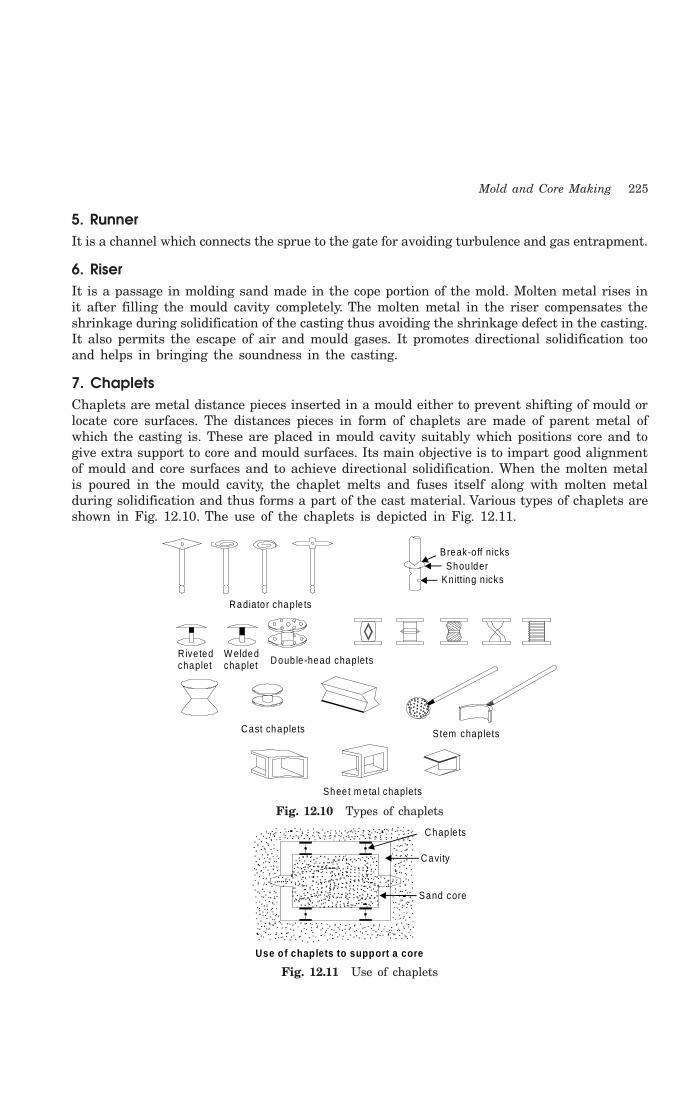
Mold and Core Making 225
5. RunnerIt is a channel which connects the sprue to the gate for avoiding turbulence and gas entrapment.
6. RiserIt is a passage in molding sand made in the cope portion of the mold. Molten metal rises init after filling the mould cavity completely. The molten metal in the riser compensates theshrinkage during solidification of the casting thus avoiding the shrinkage defect in the casting.It also permits the escape of air and mould gases. It promotes directional solidification tooand helps in bringing the soundness in the casting.
7. ChapletsChaplets are metal distance pieces inserted in a mould either to prevent shifting of mould orlocate core surfaces. The distances pieces in form of chaplets are made of parent metal ofwhich the casting is. These are placed in mould cavity suitably which positions core and togive extra support to core and mould surfaces. Its main objective is to impart good alignmentof mould and core surfaces and to achieve directional solidification. When the molten metalis poured in the mould cavity, the chaplet melts and fuses itself along with molten metalduring solidification and thus forms a part of the cast material. Various types of chaplets areshown in Fig. 12.10. The use of the chaplets is depicted in Fig. 12.11.
Break-o ff nicksShou lder
Kn itting n icks
Radiato r chap le ts
Doub le -head chapletsW eldedchaplet
R ive tedchaplet
Cast chaplets Stem chaplets
Sheet m eta l chaplets
Fig. 12.10 Types of chaplets
Chap le ts
Cavity
Sand core
Use of chaplets to support a core
Fig. 12.11 Use of chaplets

226 Introduction to Basic Manufacturing Processes and Workshop Technology
8. ChillsIn some casting, it is required to produce a hard surface at a particular place in the
casting. At that particular position, the special mould surface for fast extraction of heat is tobe made. The fast heat extracting metallic materials known as chills will be incorporatedseparately along with sand mould surface during molding. After pouring of molten metal andduring solidification, the molten metal solidifies quickly on the metallic mould surface incomparison to other mold sand surfaces. This imparts hardness to that particular surfacebecause of this special hardening treatment through fast extracting heat from that particularportion. Thus, the main function of chill is to provide a hard surface at a localized place inthe casting by way of special and fast solidification. Various types of chills used in somecasting processes are shown in Fig. 12.12. The use of a chill in the mold is depicted inFig. 12.13.
Fig. 12.12 Types of chills
Chill
Core
Ramm edM olding sand
Ch ill
Fig. 12.13 Use of a chill
12.11 FACTORS CONTROLING GATING DESIGN
The following factors must be considered while designing gating system.(i) Sharp corners and abrupt changes in at any section or portion in gating system
should be avoided for suppressing turbulence and gas entrapment. Suitablerelationship must exist between different cross-sectional areas of gating systems.
(ii) The most important characteristics of gating system besides sprue are the shape,location and dimensions of runners and type of flow. It is also important to determinethe position at which the molten metal enters the mould cavity.
(iii) Gating ratio should reveal that the total cross-section of sprue, runner and gatedecreases towards the mold cavity which provides a choke effect.
(iv) Bending of runner if any should be kept away from mold cavity.(v) Developing the various cross sections of gating system to nullify the effect of
turbulence or momentum of molten metal.(vi) Streamlining or removing sharp corners at any junctions by providing generous
radius, tapering the sprue, providing radius at sprue entrance and exit and providinga basin instead pouring cup etc.
Mold and Core Making 227
12.12 ROLE OF RISER IN SAND CASTINGMetals and their alloys shrink as they cool or solidify and hence may create a partial vacuumwithin the casting which leads to casting defect known as shrinkage or void. The primaryfunction of riser as attached with the mould is to feed molten metal to accommodate shrinkageoccurring during solidification of the casting. As shrinkage is very common casting defect incasting and hence it should be avoided by allowing molten metal to rise in riser after fillingthe mould cavity completely and supplying the molten metal to further feed the void occurredduring solidification of the casting because of shrinkage. Riser also permits the escape ofevolved air and mold gases as the mold cavity is being filled with the molten metal. It alsoindicates to the foundry man whether mold cavity has been filled completely or not. Thesuitable design of riser also helps to promote the directional solidification and hence helps inproduction of desired sound casting.
12.12.1 Considerations for Desiging RiserWhile designing risers the following considerations must always be taken into account.
(A) Freezing time1 For producing sound casting, the molten metal must be fed to the mold till it
solidifies completely. This can be achieved when molten metal in riser should freezeat slower rate than the casting.
2 Freezing time of molten metal should be more for risers than casting. The quantativerisering analysis developed by Caine and others can be followed while designingrisers.
(B) Feeding range1. When large castings are produced in complicated size, then more than one riser are
employed to feed molten metal depending upon the effective freezing range of eachriser.
2. Casting should be divided into divided into different zones so that each zone can befeed by a separate riser.
3. Risers should be attached to that heavy section which generally solidifies last in thecasting.
4. Riser should maintain proper temperature gradients for continuous feeding throughoutfreezing or solidifying.
(C) Feed Volume Capacity1 Riser should have sufficient volume to feed the mold cavity till the solidification of
the entire casting so as to compensate the volume shrinkage or contraction of thesolidifying metal.
2 The metal is always kept in molten state at all the times in risers during freezingof casting. This can be achieved by using exothermic compounds and electric arcfeeding arrangement. Thus it results for small riser size and high casting yield.
3 It is very important to note that volume feed capacity riser should be based uponfreezing time and freezing demand.
Riser system is designed using full considerations on the shape, size and the position orlocation of the riser in the mold.

228 Introduction to Basic Manufacturing Processes and Workshop Technology
12.12.2 Effect of RiserRiser size affects on heat loss from top at open risers. Top risers are expressed as a percentageof total heat lost from the rises during solidification. Risers are generally kept cylindrical.Larger the riser, greater is the percentage of heat that flows out of top. Shape of riser maybe cylindrical or cubical or of cuboids kind. If shape is cylindrical i.e. 4" high and 4" dia,insulated so that heat can pass only into the circumferential sand walls, with a constant Kvalue of 13.7 min./sq.ft. Chvorinov’s rule may be used to calculate the freezing time forcylinder as 13.7 min. The freezing time of a 4" steel cube of same sand is 6.1 minutes andthe freezing time of a 2", 8" and 8" rectangular block is also 6.1 min. Since the solidificationtime as calculated of the cylinder is nearly twice as long as that of either the block of thecube. Hence cylindrical shape is always better. Insulation and shielding of molten metal inriser also plays a good role for getting sound casting
12.13 GREEN SAND MOLDING
Green sand molding is the most widely used molding process. The green sand used formolding consists of silica, water and other additives. One typical green sand mixture contains10 to 15% clay binder, 4 to 6% water and remaining silica sand. The green sand mixture isprepared and used in the molding procedure described in section 12.8 is used to complete themold (cope and drag). Cope and drag are then assembled and molten metal is poured whilemould cavity is still green. It is neither dried nor baked. Green sand molding is preferred formaking small and medium sized castings. It can also be applied for producing non-ferrouscastings. It has some advantages which are given as under.
Advantages1 It is adaptable to machine molding2 No mould baking and drying is required.3 Mold distortion is comparatively less than dry sand molding.
12.14 CORE
Cores are compact mass of core sand (special kind of molding sand ) prepared separately thatwhen placed in mould cavity at required location with proper alignment does not allow themolten metal to occupy space for solidification in that portion and hence help to producehollowness in the casting. The environment in which the core is placed is much different fromthat of the mold. In fact the core has to withstand the severe action of hot metal whichcompletely surrounds it. They may be of the type of green sand core and dry sand core.Therefore the core must meet the following functions or objectives which are given as under.
1 Core produces hollowness in castings in form of internal cavities.2 It must be sufficiently permeable to allow the easy escape of gases during pouring
and solidification.3 It may form a part of green sand mold4 It may be deployed to improve mold surface.5 It may provide external under cut features in casting.6 It may be inserted to achieve deep recesses in the casting.7 It may be used to strengthen the mold.8 It may be used to form gating system of large size mold.

Mold and Core Making 229
12.15 CORE SAND
It is special kind of molding sand. Keeping the above mentioned objectives in view, thespecial considerations should be given while selecting core sand. Those considerationsinvolves (i) The cores are subjected to a very high temperature and hence the core sandshould be highly refractory in nature (ii) The permeability of the core sand must besufficiently high as compared to that of the molding sands so as to allow the core gasesto escape through the limited area of the core recesses generated by core prints (iii) Thecore sand should not possess such materials which may produce gases while they comein contact with molten metal and (iv) The core sand should be collapsible in nature, i.e.it should disintegrate after the metal solidifies, because this property will ease the cleaningof the casting.
The main constituents of the core sand are pure silica sand and a binder. Silica sand ispreferred because of its high refractoriness. For higher values of permeability sands withcoarse grain size distribution are used. The main purpose of the core binder is to hold thegrains together, impart strength and sufficient degree collapsibility. Beside these propertiesneeded in the core sand, the binder should be such that it produces minimum amount of gaseswhen the molt metal is poured in the mould. Although, in general the binder are inorganicas well as organic ones, but for core making, organic binders are generally preferred becausethey are combustible and can be destroyed by heat at higher temperatures thereby givingsufficient collapsibility to the core sand. The common binders which are used in making coresand as follows:
1. Cereal binderIt develops green strength, baked strength and collapsibility in core. The amount of these
binders used varies from 0.2 to 2.2% by weight in the core sand.
2. Protein binderIt is generally used to increase collapsibility property of core.
3. Thermo setting resinIt is gaining popularity nowadays because it imparts high strength, collapsibility to core
sand and it also evolve minimum amount of mold and core gases which may produce defectsin the casting. The most common binders under this group are phenol formaldehyde and ureaformaldehyde.
4. Sulphite binderSulphite binder is also sometimes used in core but along with certain amount of clay.
5. DextrinIt is commonly added in core sand for increasing collapsibility and baked strength of core
6. PitchIt is widely used to increase the hot strength of the core.
7. MolassesIt is generally used as a secondary binder to increase the hardness on baking. It is used
in the form of molasses liquid and is sprayed on the cores before baking.

230 Introduction to Basic Manufacturing Processes and Workshop Technology
8. Core oilIt is in liquid state when it is mixed with the core sand but forms a coherent solid film
holding the sand grains together when it is baked. Although, the core drying with certain coreoils occurs at room temperature but this can be expedited by increasing the temperature.That is why the cores are made with core oils and are usually baked.
12.16 CORE MAKINGCore making basically is carried out in four stages namely core sand preparation, coremaking, core baking and core finishing. Each stage is explained as under.
12.16.1 Core Sand PreparationPreparation of satisfactory and homogenous mixture of core sand is not possible by manualmeans. Therefore for getting better and uniform core sand properties using proper sandconstituents and additives, the core sands are generally mixed with the help of any of thefollowing mechanical means namely roller mills and core sand mixer using vertical revolvingarm type and horizontal paddle type mechanisms. In the case of roller mills, the rolling actionof the mulling machine along with the turning over action caused by the ploughs gives auniform and homogeneous mixing. Roller mills are suitable for core sands containing cerealbinders, whereas the core sand mixer is suitable for all types of core binders. These machinesperform the mixing of core sand constituents most thoroughly.
12.16.2 Core Making Process Using Core Making MachinesThe process of core making is basically mechanized using core blowing, core ramming andcore drawing machines which are broadly discussed as under.
12.16.2.1 Core blowing machinesThe basic principle of core blowing machine comprises of filling the core sand into the
core box by using compressed air. The velocity of the compressed air is kept high to obtaina high velocity of core sand particles, thus ensuring their deposit in the remote corners thecore box. On entering the core sand with high kinetic energy, the shaping and ramming ofcore is carried out simultaneously in the core box. The core blowing machines can be furtherclassified into two groups namely small bench blowers and large floor blowers. Small benchblowers are quite economical for core making shops having low production. The bench blowerswere first introduced during second war. Because of the high comparative productivity andsimplicity of design, bench blowers became highly popular. The cartridge oriented sand magazineis considered to be a part of the core box equipment. However, one cartridge may be usedfor several boxes of approximately the same size. The cartridge is filled using hands. Thenthe core box and cartridge are placed in the machine for blowing and the right handle of themachine clamps the box and the left handle blows the core. In a swing type bench blower,the core sand magazine swings from the blowing to the filling position. There is also anothertype of bench blowing, which has a stationary sand magazine. It eliminates the time and effortof moving the magazine from filling to the blowing position. The floor model blowers havethe advantage being more automation oriented. These floor model blowers possess stationarysand magazine and automatic control. One of the major drawbacks in core blowing is thechanneling of sand in the magazine which may be prevented by agitating the sand in the sandmagazine.

Mold and Core Making 231
12.16.2.2 Core ramming machinesCores can also be prepared by ramming core sands in the core boxes by machines based
on the principles of squeezing, jolting and slinging. Out of these three machines, jolting andslinging are more common for core making.
12.16.2.3 Core drawing machinesThe core drawing is preferred when the core boxes have deep draws. After ramming sand
in it, the core box is placed on a core plate supported on the machine bed. A rapping actionon the core box is produced by a vibrating vertical plate. This rapping action helps in drawingoff the core from the core box. After rapping, the core box, the core is pulled up thus leavingthe core on the core plate. The drawn core is then baked further before its use in mold cavityto produce hollowness in the casting.
12.16.3 Core bakingOnce the cores are prepared, they will be baked in a baking ovens or furnaces. The mainpurpose of baking is to drive away the moisture and hard en the binder, thereby givingstrength to the core. The core drying equipments are usually of two kinds namely core ovensand dielectric bakers. The core ovens are may be further of two type’s namely continuoustype oven and batch type oven. The core ovens and dielectric bakers are discussed as under.
12.16.3.1 Continuous type ovensContinuous type ovens are preferred basically for mass production. In these types, core carrying
conveyors or chain move continuously through the oven. The baking time is controlled by the speedof the conveyor. The continuous type ovens are generally used for baking of small cores.
12.16.3.2 Batch type ovensBatch type ovens are mainly utilized for baking variety of cores in batches. The cores
are commonly placed either in drawers or in racks which are finally placed in the ovens. Thecore ovens and dielectric bakers are usually fired with gas, oil or coal.
12.16.3.3 Dielectric bakersThese bakers are based on dielectric heating. The core supporting plates are not used
in this baker because they interfere with the potential distribution in the electrostatic field.To avoid this interference, cement bonded asbestos plates may be used for supporting thecores. The main advantage of these ovens is that they are faster in operation and a goodtemperature control is possible with them.
After baking of cores, they are smoothened using dextrin and water soluble binders.
12.16.4 CORE FINISHINGThe cores are finally finished after baking and before they are finally set in the mould. Thefins, bumps or other sand projections are removed from the surface of the cores by rubbingor filing. The dimensional inspection of the cores is very necessary to achieve sound casting.Cores are also coated with refractory or protective materials using brushing dipping andspraying means to improve their refractoriness and surface finish. The coating on coreprevents the molten metal from entering in to the core.
Bars, wires and arbors are generally used to reinforce core from inside as per size of coreusing core sand. For handling bulky cores, lifting rings are also provided.
232 Introduction to Basic Manufacturing Processes and Workshop Technology
12.17 GREEN SAND CORES
Green sand cores are made by green sand containing moist condition about 5% water and 15-30 % clay. It imparts very good permeability to core and thus avoids defects like shrinkageor voids in the casting. Green sand cores are not dried. They are poured in green conditionand are generally preferred for simple, small and medium castings. The process of makinggreen sand core consumes less time. Such cores possess less strength in comparison to drysand cores and hence cannot be stored for longer period.
12.18 DRY SAND CORES
Dry sand cores are produced by drying the green sand cores to about 110°C. These corespossess high strength rigidity and also good thermal stability. These cores can be stored forlong period and are more stable than green sand core. They are used for large castings. Theyalso produce good surface finish in comparison to green sand cores. They can be handled moreeasily. They resist metal erosion. These types of cores require more floor space, more corematerial, high labor cost and extra operational equipment.
12.19 CLASSIFICATION OF MOLDING PROCESSES
Molding processes can be classified in a number of ways. Broadly they are classifiedeither on the basis of the method used or on the basis of the mold material used.
(i) Classification based on the method used
(a) Bench molding. (b) Floor molding,
(c) Pit molding. (d) Machine molding.
(ii) Classification based on the mold material used:
(a) Sand molding:
1. Green sand mould
2. Dry sand mould,
3. Skin dried mould.
4. Core sand mould.
5. loam mould
6. Cement bonded sand mould
7. Carbon-dioxide mould.
8. Shell mould.
(b) Plaster molding,
(c) Metallic molding.
(d) Loam molding
Some of the important molding methods are discussed as under.
12.20 MOLDING METHODS
Commonly used traditional methods of molding are bench molding, floor molding, pit moldingand machine molding. These methods are discussed as under.

Mold and Core Making 233
12.20.1 Bench MoldingThis type of molding is preferred for small jobs. The whole molding operation is carried outon a bench of convenient height. In this process, a minimum of two flasks, namely cope anddrag molding flasks are necessary. But in certain cases, the number of flasks may increasedepending upon the number of parting surfaces required.
12.20.2 Floor MoldingThis type of molding is preferred for medium and large size jobs. In this method, only dragportion of molding flask is used to make the mold and the floor itself is utilized as drag andit is usually performed with dry sand.
12.20.3 Pit MoldingUsually large castings are made in pits instead of drag flasks because of their huge size. Inpit molding, the sand under the pattern is rammed by bedding-in process. The walls and thebottom of the pit are usually reinforced with concrete and a layer of coke is laid on the bottomof the pit to enable easy escape of gas. The coke bed is connected to atmosphere through ventpipes which provide an outlet to the gases. One box is generally required to complete themold, runner, sprue, pouring basin and gates are cut in it.
12.20.4 Machine MoldingFor mass production of the casting, the general hand molding technique proves un economicaland in efficient. The main advantage of machine molding, besides the saving of labor andworking time, is the accuracy and uniformity of the castings which can otherwise be onlyobtained with much time and labor. Or even the cost of machining on the casting can bereduced drastically because it is possible to maintain the tolerances within narrow limits oncasting using machine molding method. Molding machines thus prepare the moulds at afaster rate and also eliminate the need of employing skilled molders. The main operationsperformed by molding machines are ramming of the molding sand, roll over the mold, formgate, rapping the pattern and its withdrawal. Most of the mold making operations are performedusing molding machines
12.19.5 Loam MoldingLoam molding uses loam sand to prepare a loam mold. It is such a molding process in whichuse of pattern is avoided and hence it differs from the other molding processes. Initially theloam sand is prepared with the mixture of molding sand and clay made in form of a pasteby suitable addition of clay water. Firstly a rough structure of cast article is made by handusing bricks and loam sand and it is then given a desired shape by means of strickles andsweep patterns. Mould is thus prepared. It is then baked to give strength to resist the flowof molten metal. This method of molding is used where large castings are required innumbers. Thus it enables the reduction in time, labor and material which would have beenspent in making a pattern. But this system is not popular for the reason that it takes lotsof time in preparing mould and requires special skill. The cope and drag part of mould areconstructed separately on two different iron boxes using different sizes of strickles and sweepsetc. and are assembled together after baking. It is important to note that loam moulds aredried slowly and completely and used for large regular shaped castings like chemical pans,drums etc.
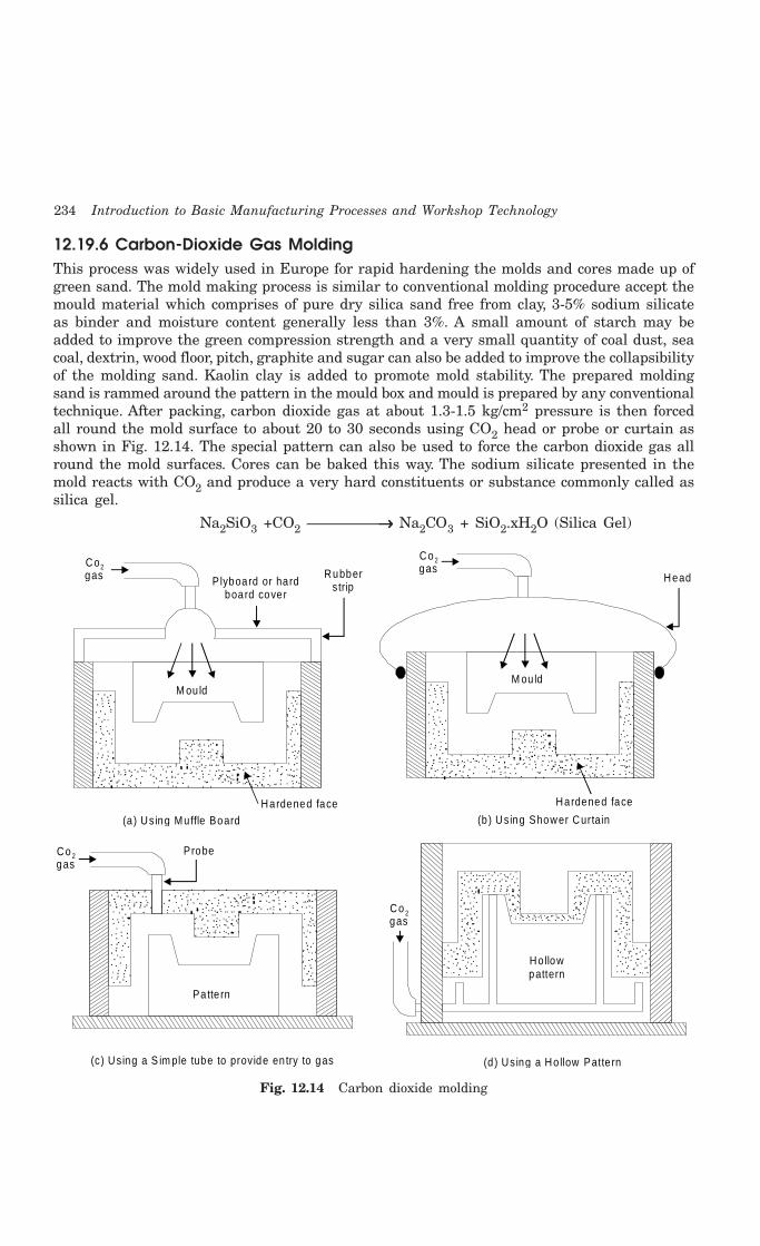
234 Introduction to Basic Manufacturing Processes and Workshop Technology
12.19.6 Carbon-Dioxide Gas MoldingThis process was widely used in Europe for rapid hardening the molds and cores made up ofgreen sand. The mold making process is similar to conventional molding procedure accept themould material which comprises of pure dry silica sand free from clay, 3-5% sodium silicateas binder and moisture content generally less than 3%. A small amount of starch may beadded to improve the green compression strength and a very small quantity of coal dust, seacoal, dextrin, wood floor, pitch, graphite and sugar can also be added to improve the collapsibilityof the molding sand. Kaolin clay is added to promote mold stability. The prepared moldingsand is rammed around the pattern in the mould box and mould is prepared by any conventionaltechnique. After packing, carbon dioxide gas at about 1.3-1.5 kg/cm2 pressure is then forcedall round the mold surface to about 20 to 30 seconds using CO2 head or probe or curtain asshown in Fig. 12.14. The special pattern can also be used to force the carbon dioxide gas allround the mold surfaces. Cores can be baked this way. The sodium silicate presented in themold reacts with CO2 and produce a very hard constituents or substance commonly called assilica gel.
Na2SiO3 +CO2 —————→→→→→ Na2CO3 + SiO2.xH2O (Silica Gel)
Co 2 gas
Head
M ou ld
Hardened face
(b) Using Shower Curtain
P lyboard or hardboard cover
Rubberstrip
M ou ld
Hardened face(a) Using Muffle Board
Co2 gas
Co 2 gas
Ho llowpattern
(d ) Using a Ho llow Patte rn
Co 2 gas
Probe
Patte rn
(c) Using a S im ple tube to prov ide en try to gas
Fig. 12.14 Carbon dioxide molding
Mold and Core Making 235
This hard substance is like cement and helps in binding the sand grains. Molds and coresthus prepared can be used for pouring molten metal for production of both ferrous and non-ferrous casting. The operation is quick, simple require semi-skilled worker. The evolution ofgases is drastically reduced after pouring the thus prepared mould. This process eliminatesmold and core baking oven. Reclamation of used sand is difficult for this process
Few other special molding methods are also discussed as under
12.20.6 Shell MoldingShell mold casting is recent invention in molding techniques for mass production and smoothfinish. Shell molding method was invented in Germany during the Second World War. It isalso known as Carning or C process which is generally used for mass production of accuratethin castings with close tolerance of +_ 0.02 mm and with smooth surface finish. It consistsof making a mould that has two or more thin lines shells (shell line parts, which aremoderately hard and smooth. Molding sand is prepared using thermosetting plastic dry powderand find sand are uniformly mixed in a muller in the ratio 1: 20. In this process the patternis placed on a metal plate and silicon grease is then sprayed on it. The pattern is then heatedto 205°C to 230°C and covered with resin bonded sand. After 30 second a hard layer of sandis formed over the pattern. Pattern and shell are then heated and treated in an oven at 315°Cfor 60 sec. Then, the shell so formed as the shape of the pattern is ready to strip from thepattern. The shell can be made in two or more pieces as per the shape of pattern. Similarlycore can be made by this process. Finally shells are joined together to form the mold cavity.Then the mold is ready for pouring the molten metal to get a casting. The shell so formedhas the shape of pattern formed of cavity or projection in the shell. In case of unsymmetricalshapes, two patterns are prepared so that two shell are produced which are joined to formproper cavity. Internal cavity can be formed by placing a core. Hot pattern and box iscontaining a mixture of sand and resin. Pattern and box inverted and kept in this positionfor some time. Now box and pattern are brought to original position. A shell of resin-bondedsand sticks to the pattern and the rest falls. Shell separates from the pattern with the helpof ejector pins. It is a suitable process for casting thin walled articles. The cast shapes areuniform and their dimensions are within close limit of tolerance ± 0.002 mm and it is suitablefor precise duplication of exact parts.
The shells formed by this process are 0.3 to 0.6 mm thick and can be handled and stored.Shell moulds are made so that machining parts fit together-easily, held clamps or adhesiveand metal is poured either in a vertical or horizontal position. They are supported in rocksor mass of bulky permeable material such as sand steel shot or gravel. Thermosettingplastics, dry powder and sand are mixed ultimately in a muller. The process of shell moldingpossesses various advantages and disadvantages. Some of the main advantages anddisadvantages of this process are given as under.
AdvantagesThe main advantages of shell molding are:
(i) High suitable for thin sections like petrol engine cylinder.
(ii) Excellent surface finish.
(iii) Good dimensional accuracy of order of 0.002 to 0.003 mm.
(iv) Negligible machining and cleaning cost.
(v) Occupies less floor space.
236 Introduction to Basic Manufacturing Processes and Workshop Technology
(vi) Skill-ness required is less.
(vii) Moulds formed by this process can be stored until required.
(viii) Better quality of casting assured.
(ix) Mass production.
(x) It allows for greater detail and less draft.
(xi) Unskilled labor can be employed.
(xii) Future of shell molding process is very bright.
DisadvantagesThe main disadvantages of shell molding are:
1. Higher pattern cost.
2. Higher resin cost.
3. Not economical for small runs.
4. Dust-extraction problem.
5. Complicated jobs and jobs of various sizes cannot be easily shell molded.
6. Specialized equipment is required.
7. Resin binder is an expensive material.
8. Limited for small size.
12.20.7 Plaster MoldingPlaster molding process is depicted through Fig. 12.15. The mould material in plaster moldingis gypsum or plaster of paris. To this plaster of paris, additives like talc, fibers, asbestos, silicaflour etc. are added in order to control the contraction characteristics of the mould as wellas the settling time. The plaster of paris is used in the form of a slurry which is made to aconsistency of 130 to 180. The consistency of the slurry is defined as the pounds of water per100 pounds of plaster mixture. This plaster slurry is poured over a metallic pattern confinedin a flask. The pattern is usually made of brass and it is generally in the form of half portionof job to be cast and is attached firmly on a match plate which forms the bottom of themolding flask. Wood pattern are not used because the water in the plaster raises the grainson them and makes them difficult to be withdrawn. Some parting or release agent is neededfor easy withdrawal of the pattern from the mold. As the flask is filled with the slurry, it isvibrated so as to bubble out any air entrapped in the slurry and to ensure that the mouldis completely filled up. The plaster material is allowed to set. Finally when the plaster is setproperly the pattern is then withdrawn by separating the same, from the plaster by blowingcompressed air through the holes in the patterns leading to the parting surface between thepattern and the plaster mold. The plaster mold thus produced is dried in an oven to atemperature range between 200-700 degree centigrade and cooled in the oven itself. In theabove manner two halves of a mould are prepared and are joined together to form the propercavity. The necessary sprue, runner etc. are cut before joining the two parts.

Mold and Core Making 237
Pouring basin
Drag
(c) Assem bly
Cope
(b) M old making
Patte rn
Plaste rs lu rry
P laste r s lu rry(G ypsum + water)
(a ) S lurry m aking
Stirre r
Fig. 12.15 Plaster molding
Advantages(a) In plaster molding, very good surface finish is obtained and machining cost is also
reduced.
(b) Slow and uniform rate of cooling of the casting is achieved because of low thermalconductivity of plaster and possibility of stress concentration is reduced.
(c) Metal shrinkage with accurate control is feasible and thereby warping and distortionof thin sections can be avoided in the plaster molding.
Limitations(a) There is evolution of steam during metal pouring if the plaster mold is not dried
at higher temperatures avoid this, the plaster mold may be dehydrated at hightemperatures, but the strength of the mould decreases with dehydration.
(b) The permeability of the plaster mold is low. This may be to a certain extent but itcan be increased by removing the bubbles as the plaster slurry is mixed in amechanical mixer.
12.20.8 Antioch ProcessThis is a special case of plaster molding which was developed by Morris Bean. It is very wellsuited to high grade aluminum castings. The process differs from the normal plaster moldingin the fact that in this case once the plaster sets the whole thing is auto-laved in saturatedsteam at about 20 psi. Then the mold is dried in air for about 10 to 12 hours and finally inan oven for 10 to 20 hours at about 250°C. The autoclaving and drying processes create agranular structure in the mold structure which increases its permeability.
12.20.9 Metallic MoldingMetallic mold is also known as permanent mold because of their long life. The metallic moldcan be reused many times before it is discarded or rebuilt. Permanent molds are made ofdense, fine grained, heat resistant cast iron, steel, bronze, anodized aluminum, graphite orother suitable refractoriness. The mold is made in two halves in order to facilitate theremoval of casting from the mold. Usually the metallic mould is called as dies and the metalis introduced in it under gravity.
Some times this operation is also known as gravity die casting. When the molten metalis introduced in the die under pressure, then this process is called as pressure die casting.It may be designed with a vertical parting line or with a horizontal parting line as in
238 Introduction to Basic Manufacturing Processes and Workshop Technology
conventional sand molds. The mold walls of a permanent mold have thickness from 15 mmto 50 mm. The thicker mold walls can remove greater amount of heat from the casting. Thisprovides the desirable chilling effect. For faster cooling, fins or projections may be providedon the outside of the permanent mold. Although the metallic mould can be used both forferrous and nonferrous castings but this process is more popular for the non-ferrous castings,for examples aluminum alloys, zinc alloys and magnesium alloys. Usually the metallic moldsare made of grey iron, alloy steels and anodized aluminum alloys. There are some advantages,dis-advantages and applications of metallic molding process which are discussed as under.
Advantages(i) Fine and dense grained structure in casting is achieved using such mold.
(ii) No blow holes exist in castings produced by this method.
(iii) The process is economical.
(iv) Because of rapid rate of cooling, the castings possess fine grain structure.
(v) Close dimensional tolerance is possible.
(vi) Good surface finish and surface details are obtained.
(vii) Casting defects observed in sand castings are eliminated.
(viii) Fast rate of production can be attained.
(ix) The process requires less labor.
Disadvantages(i) The surface of casting becomes hard due to chilling effect.
(ii) High refractoriness is needed for high melting point alloys.
(iii) The process is impractical for large castings.
Applications1 This method is suitable for small and medium sized casting.
2 It is widely suitable for non-ferrous casting.
12.21 QUESTIONS1. Explain briefly the main constituents of molding sand.
2. How do the grain size and shape affect the performance of molding sand?
3. How natural molding sands differ from synthetic sands? Name major sources of obtainingnatural molding sands in India?
4. How are binders classified?
5. Describe the process of molding sand preparation and conditioning.
6. Name and describe the different properties of good molding sand.
7. What are the common tests performed on molding sands?
8. Name and describe briefly the different additives commonly added to the molding sand forimproving the properties of the molding sand.
9. What are the major functions of additives in molding sands?
10. Classify and discuss the various types of molding sand. What are the main factors whichinfluence the selection of particular molding sand for a specific use?
Mold and Core Making 239
11. What is meant by green strength and dry strength as applied to a molding sand?
12. What is grain fineness number? Explain how you will use a sieve shaker for determining thegrain fineness of foundry sand.
13. How will you test the moisture content and clay content in molding sand?
14. Using the neat sketches, describe procedural steps to be followed in making dry sand mold.
15. Differentiate between the process of green sand molding and dry sand molding.
16. Sketch a complete mold and indicate on it the various terms related to it and their functions.
17. Discuss briefly the various types of molds.
18. Explain the procedure of making a mold using a split pattern.
19. Write short notes of the following:
(i) Floor molding
(ii) Pit molding
(iii) Bench molding
(iv) Machine molding
(v) Loam molding.
(vi) Plaster molding.
(vii) Metallic molding.
20. Describe the following:
(i) Skin dried molds
(ii) Air dried molds
(iii) CO2 molds
(iv) Plaster molds.
21. What do you understand by the term gating system?
22. What are chaplets and why are they used?
23. Using neat sketches, describe various types of chaplets.
24. What do you understand by the term gating system?
25. What are the main requirements expected of an ideal gating system?
26. What are different types of gates? Explain them with the help of sketches stating the relativemerits and demerits of each.
27. What is chill? Explain in brief its uses.
28. What is meant by the term ‘risering’?
29. Discuss the common objectives of risers.
30. What advantages are provided by a riser?
31. What is the best shape of a riser, and why?
32. Why is cylindrical shape risers most commonly used?
33. What are the advantages of blind riser over conventional type riser?
34. Write short notes on the following terms:
(i) Use of padding
(ii) Use of exothermic materials and
(iii) Use of chills to help proper directional solidification.

240 Introduction to Basic Manufacturing Processes and Workshop Technology
35. Describe the process of shell molding indicating:
(i) Composition of sand mixture
(ii) Steps in molding
(iii) Advantages
(iv) Limitations and
(v) Applications.
36. Describe the CO2–gas molding process in detail using suitable sketches and stat itsadvantages, disadvantages and applications.
37. What is a core? What purposes are served by cores?
38. What are the characteristics of a good core?
39. Classify the types of cores? Explain them with the help of sketches specifying their commonapplications.
40. What is a core binder?
41. What is core print?
42. Describe different types of core sand.
43. Describe hand core making and machine core making.
44. How are the cores finished and inspected?
45. What is the function of the core in sand molding? How are cores held in place in mold? Andhow are they supported?
46. Distinguish between green sand cores and dry sand cores?
47. Name the different steps in core-making? Describe the operation of making a dry sand core?
48. What are the different stages in core making?
49. What are the different types of machines used in core-making?
50. Describe the following terms used in core-making.
(i) Core drying,
(ii) Core finishing
(iii) Use of rods, wires, arbors and lifting rings.
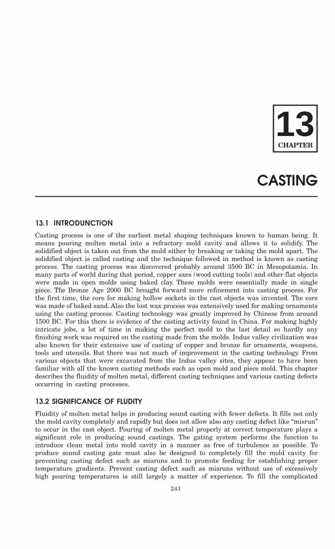
241
CASTING
13.1 INTRODUNCTION
Casting process is one of the earliest metal shaping techniques known to human being. Itmeans pouring molten metal into a refractory mold cavity and allows it to solidify. Thesolidified object is taken out from the mold either by breaking or taking the mold apart. Thesolidified object is called casting and the technique followed in method is known as castingprocess. The casting process was discovered probably around 3500 BC in Mesopotamia. Inmany parts of world during that period, copper axes (wood cutting tools) and other flat objectswere made in open molds using baked clay. These molds were essentially made in singlepiece. The Bronze Age 2000 BC brought forward more refinement into casting process. Forthe first time, the core for making hollow sockets in the cast objects was invented. The corewas made of baked sand. Also the lost wax process was extensively used for making ornamentsusing the casting process. Casting technology was greatly improved by Chinese from around1500 BC. For this there is evidence of the casting activity found in China. For making highlyintricate jobs, a lot of time in making the perfect mold to the last detail so hardly anyfinishing work was required on the casting made from the molds. Indus valley civilization wasalso known for their extensive use of casting of copper and bronze for ornaments, weapons,tools and utensils. But there was not much of improvement in the casting technology. Fromvarious objects that were excavated from the Indus valley sites, they appear to have beenfamiliar with all the known casting methods such as open mold and piece mold. This chapterdescribes the fluidity of molten metal, different casting techniques and various casting defectsoccurring in casting processes.
13.2 SIGNIFICANCE OF FLUDITY
Fluidity of molten metal helps in producing sound casting with fewer defects. It fills not onlythe mold cavity completely and rapidly but does not allow also any casting defect like “misrun”to occur in the cast object. Pouring of molten metal properly at correct temperature plays asignificant role in producing sound castings. The gating system performs the function tointroduce clean metal into mold cavity in a manner as free of turbulence as possible. Toproduce sound casting gate must also be designed to completely fill the mold cavity forpreventing casting defect such as misruns and to promote feeding for establishing propertemperature gradients. Prevent casting defect such as misruns without use of excessivelyhigh pouring temperatures is still largely a matter of experience. To fill the complicated
13CHAPTER
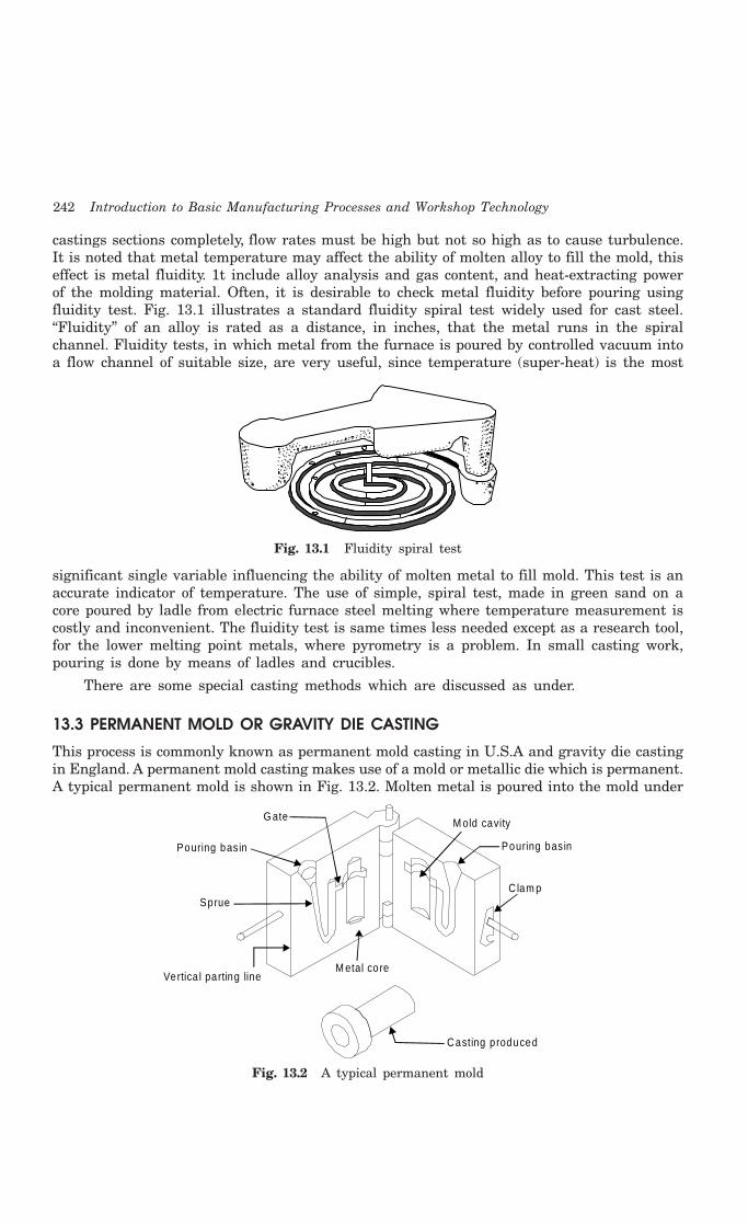
242 Introduction to Basic Manufacturing Processes and Workshop Technology
castings sections completely, flow rates must be high but not so high as to cause turbulence.It is noted that metal temperature may affect the ability of molten alloy to fill the mold, thiseffect is metal fluidity. 1t include alloy analysis and gas content, and heat-extracting powerof the molding material. Often, it is desirable to check metal fluidity before pouring usingfluidity test. Fig. 13.1 illustrates a standard fluidity spiral test widely used for cast steel.“Fluidity” of an alloy is rated as a distance, in inches, that the metal runs in the spiralchannel. Fluidity tests, in which metal from the furnace is poured by controlled vacuum intoa flow channel of suitable size, are very useful, since temperature (super-heat) is the most
Fig. 13.1 Fluidity spiral test
significant single variable influencing the ability of molten metal to fill mold. This test is anaccurate indicator of temperature. The use of simple, spiral test, made in green sand on acore poured by ladle from electric furnace steel melting where temperature measurement iscostly and inconvenient. The fluidity test is same times less needed except as a research tool,for the lower melting point metals, where pyrometry is a problem. In small casting work,pouring is done by means of ladles and crucibles.
There are some special casting methods which are discussed as under.
13.3 PERMANENT MOLD OR GRAVITY DIE CASTING
This process is commonly known as permanent mold casting in U.S.A and gravity die castingin England. A permanent mold casting makes use of a mold or metallic die which is permanent.A typical permanent mold is shown in Fig. 13.2. Molten metal is poured into the mold under
Pouring basin
G ate M old cavity
C lam p
M etal co re
Sprue
Vertica l parting line
Casting p roduced
Pouring basin
Fig. 13.2 A typical permanent mold

Casting 243
gravity only and no external pressure is applied to force the liquid metal into the mold cavity.However, the liquid metal solidifies under pressure of metal in the risers, etc. The metallicmold can be reused many times before it is discarded or rebuilt. These molds are made ofdense, fine grained, heat resistant cast iron, steel, bronze, anodized aluminum, graphite orother suitable refractoriness. The mold is made in two halves in order to facilitate theremoval of casting from the mold. It may be designed with a vertical parting line or with ahorizontal parting line as in conventional sand molds. The mold walls of a permanent moldhave thickness from 15 mm to 50 mm. The thicker mold walls can remove greater amountof heat from the casting. For faster cooling, fins or projections may be provided on the outsideof the permanent mold. This provides the desirable chilling effect. There are some advantages,disadvantages and application of this process which are given as under.
Advantages(i) Fine and dense grained structure is achieved in the casting.
(ii) No blow holes exist in castings produced by this method.
(iii) The process is economical for mass production.
(iv) Because of rapid rate of cooling, the castings possess fine grain structure.
(v) Close dimensional tolerance or job accuracy is possible to achieve on the castproduct.
(vi) Good surface finish and surface details are obtained.
(vii) Casting defects observed in sand castings are eliminated.
(viii) Fast rate of production can be attained.
(ix) The process requires less labor.
Disadvantages(i) The cost of metallic mold is higher than the sand mold. The process is impractical
for large castings.
(ii) The surface of casting becomes hard due to chilling effect.
(iii) Refractoriness of the high melting point alloys.
Applications(i) This method is suitable for small and medium sized casting such as carburetor
bodies, oil pump bodies, connecting rods, pistons etc.
(ii) It is widely suitable for non-ferrous casting.
13.3 SLUSH CASTING
Slush casting is an extension of permanent mold casting or metallic mold casting. It is usedwidely for production of hollow casting without the use of core. The process is similar tometallic mold casting only with the difference that mold is allowed to open at an early stage(only when a predetermined amount of molten metal has solidified up to some thickness) andsome un-solidified molten metal fall down leaving hollowness in the cast object. The processfinds wide applications in production of articles namely toys, novelties, statutes, ornaments,lighting fixtures and other articles having hollowness inside the cast product.

244 Introduction to Basic Manufacturing Processes and Workshop Technology
13.4 PRESSURE DIE CASTING
Unlike permanent mold or gravity die casting, molten metal is forced into metallic moldor die under pressure in pressure die casting. The pressure is generally created by compressedair or hydraulically means. The pressure varies from 70 to 5000 kg/cm2 and is maintainedwhile the casting solidifies. The application of high pressure is associated with the highvelocity with which the liquid metal is injected into the die to provide a unique capacity forthe production of intricate components at a relatively low cost. This process is called simplydie casting in USA. The die casting machine should be properly designed to hold and operatea die under pressure smoothly. There are two general types of molten metal ejectionmechanisms adopted in die casting set ups which are:
(i) Hot chamber type
(a) Gooseneck or air injection management
(b) Submerged plunger management
(ii) Cold chamber type
Die casting is widely used for mass production and is most suitable for non-ferrousmetals and al1oys of low fusion temperature. The casting process is economic and rapid. Thesurface achieved in casting is so smooth that it does not require any finishing operation. Thematerial is dense and homogeneous and has no possibility of sand inclusions or other castimpurities. Uniform thickness on castings can also be maintained.
The principal base metals most commonly employed in the casting are zinc, aluminum,and copper, magnesium, lead and tin. Depending upon the melting point temperature of alloysand their suitability for the die casting, they are classified as high melting point (above 540°C)and low melting point (below 500°C) alloys. Under low category involves zinc, tin and leadbase alloys. Under high temperature category aluminum and copper base alloys are involved.
There are four main types of die-casting machine which are given as under.
1. Hot chamber die casting machine
2. Cold chamber die casting machine.
3. Air blown or goose neck type machine
4. Vacuum die-casting machine
Some commonly used die casting processes are discussed as under.
Hot chamber die-castingHot chamber die-casting machine is the oldest of die-casting machines which is simplest tooperate. It can produce about 60 or more castings of up to 20 kg each per hour and severalhundred castings per hour for single impression castings weighing a few grams. The meltingunit of setup comprises of an integral part of the process. The molten metal possessesnominal amount of superheat and, therefore, less pressure is needed to force the liquid metalinto the die. This process may be of gooseneck or air-injection type or submerged plungertype-air blown or goose neck type machine is shown as in Fig. 13.3. It is capable of performingthe following functions:
(i) Holding two die halves finally together.
(ii) Closing the die.
(iii) Injecting molten metal into die.
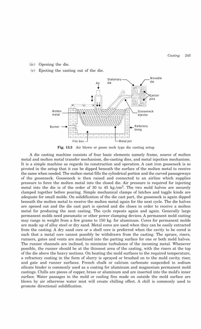
Casting 245
(iv) Opening the die.
(v) Ejecting the casting out of the die.
Stationaryd ie
M ovabled ie
E jecto rp ins
G ooseneckin jector
Refecto rylining
Air
Burner
Fire box M etal po t
M oltenm etal
Fig. 13.3 Air blown or goose neck type die casting setup
A die casting machine consists of four basic elements namely frame, source of moltenmetal and molten metal transfer mechanism, die-casting dies, and metal injection mechanism.It is a simple machine as regards its construction and operation. A cast iron gooseneck is sopivoted in the setup that it can be dipped beneath the surface of the molten metal to receivethe same when needed. The molten metal fills the cylindrical portion and the curved passagewaysof the gooseneck. Gooseneck is then raised and connected to an airline which suppliespressure to force the molten metal into the closed die. Air pressure is required for injectingmetal into the die is of the order of 30 to 45 kg./cm2. The two mold halves are securelyclamped together before pouring. Simple mechanical clamps of latches and toggle kinds areadequate for small molds. On solidification of the die cast part, the gooseneck is again dippedbeneath the molten metal to receive the molten metal again for the next cycle. The die halvesare opened out and the die cast part is ejected and die closes in order to receive a moltenmetal for producing the next casting. The cycle repeats again and again. Generally largepermanent molds need pneumatic or other power clamping devices. A permanent mold castingmay range in weight from a few grams to 150 kg. for aluminum. Cores for permanent moldsare made up of alloy steel or dry sand. Metal cores are used when they can be easily extractedfrom the casting. A dry sand core or a shell core is preferred when the cavity to be cored issuch that a metal core cannot possibly be withdrawn from the casting. The sprues, risers,runners, gates and vents are machined into the parting surface for one or both mold halves.The runner channels are inclined, to minimize turbulence of the incoming metal. Wheneverpossible, the runner should be at the thinnest area of the casting, with the risers at the topof the die above the heavy sections. On heating the mold surfaces to the required temperature,a refractory coating in the form of slurry is sprayed or brushed on to the mold cavity, riser,and gate and runner surfaces. French chalk or calcium carbonate suspended in sodiumsilicate binder is commonly used as a coating for aluminum and magnesium permanent moldcastings. Chills are pieces of copper, brass or aluminum and are inserted into the mold’s innersurface. Water passages in the mold or cooling fins made on outside the mold surface areblown by air otherwise water mist will create chilling effect. A chill is commonly used topromote directional solidification.
246 Introduction to Basic Manufacturing Processes and Workshop Technology
Cold chamber die castingCold chamber die casting process differs from hot chamber die casting in following respects.
1. Melting unit is generally not an integral part of the cold chamber die casting machine.Molten metal is brought and poured into die casting machine with help of ladles.
2. Molten metal poured into the cold chamber casting machine is generally at lowertemperature as compared to that poured in hot chamber die casting machine.
3. For this reasoning, a cold chamber die casting process has to be made use ofpressure much higher (of the order of 200 to 2000 kgf/cm2) than those applied inhot chamber process.
4. High pressure tends to increase the fluidity of molten metal possessing relativelylower temperature.
5. Lower temperature of molten metal accompanied with higher injection pressurewith produce castings of dense structure sustained dimensional accuracy and freefrom blow-holes.
6. Die components experience less thermal stresses due to lower temperature of moltenmetal. However, the dies are often required to be made stronger in order to bearhigher pressures.
There are some advantages, disadvantages and application of this process which aregiven as under.
Advantages1. It is very quick process
2. It is used for mass production
3. castings produced by this process are greatly improved surface finish
4. Thin section (0.5 mm Zn, 0.8 mm Al and 0.7 mm Mg) can be easily casted
5. Good tolerances
6. Well defined and distinct surface
7. Less nos. of rejections
8. Cost of production is less
9. Process require less space
10. Very economic process
11. Life of die is long
12. All casting has same size and shape.
Disadvantages 1. Cost of die is high.
2. Only thin casting can be produced.
3. Special skill is required.
4. Unless special precautions are adopted for evaluation of air from die-cavity some airis always entrapped in castings causing porosity.
5. It is not suitable for low production.
Casting 247
Applications1. Carburetor bodies
2. Hydraulic brake cylinders
3. Refrigeration castings
4. Washing machine
5. Connecting rods and automotive pistons
6. Oil pump bodies
7. Gears and gear covers
8. Aircraft and missile castings, and
9. Typewriter segments
13.5 ADVANTAGES OF DIE CASTING OVER SAND CASTING
1. Die casting requires less floor space in comparison to sand casting.
2. It helps in providing precision dimensional control with a subsequent reduction inmachining cost.
3. It provides greater improved surface finish.
4. Thin section of complex shape can be produced in die casting.
5. More true shape can be produced with close tolerance in die casting.
6. Castings produced by die casting are usually less defective.
7. It produces more sound casting than sand casting.
8. It is very quick process.
9. Its rate of production is high as much as 800 casting / hour.
13.6 COMPARISON BETWEEN PERMANENT MOLD CASTING AND DIE CASTING
The comparison between permanent mold castings and die casting given as under in Table13.1.
Table 13.1 Comparison between Permanent Mold Castings and Die Casting
S.No. Permanent Mold Castings Die Casting
1. Permanent mold casting are less costly Die casting dies are costly
2. It requires some more floor area in comparison It requires less floor area.to die casting
3. It gives good surface finishing It gives very fine surface finishing
4. It requires less skill It requires skill in maintenance of dieor mold
5. Production rate is good Production rate is very high
6. It has high dimensional accuracies It also have very high dimensionalaccuracies
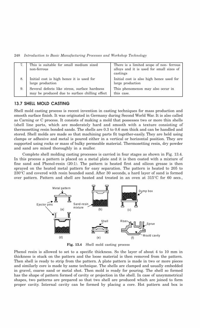
248 Introduction to Basic Manufacturing Processes and Workshop Technology
7. This is suitable for small medium sized There is a limited scope of non- ferrousnon-ferrous alloys and it is used for small sizes of
castings
8. Initial cost is high hence it is used for Initial cost is also high hence used forlarge production large production
9. Several defects like stress, surface hardness This phenomenon may also occur inmay be produced due to surface chilling effect this case.
13.7 SHELL MOLD CASTING
Shell mold casting process is recent invention in casting techniques for mass production andsmooth surface finish. It was originated in Germany during Second World War. It is also calledas Carning or C process. It consists of making a mold that possesses two or more thin shells(shell line parts, which are moderately hard and smooth with a texture consisting ofthermosetting resin bonded sands. The shells are 0.3 to 0.6 mm thick and can be handled andstored. Shell molds are made so that machining parts fit together-easily. They are held usingclamps or adhesive and metal is poured either in a vertical or horizontal position. They aresupported using rocks or mass of bulky permeable material. Thermosetting resin, dry powderand sand are mixed thoroughly in a muller.
Complete shell molding casting processes is carried in four stages as shown in Fig. 13.4.In this process a pattern is placed on a metal plate and it is then coated with a mixture offine sand and Phenol-resin (20:1). The pattern is heated first and silicon grease is thensprayed on the heated metal pattern for easy separation. The pattern is heated to 205 to230°C and covered with resin bounded sand. After 30 seconds, a hard layer of sand is formedover pattern. Pattern and shell are heated and treated in an oven at 315°C for 60 secs.,
M etal pa tte rn
R iserSprue
M ou ld cavity (f)
(a ) (b ) (c)
(d ) (e )
E jecto r p ins Sand-resinm ixtu re
Shell
Dump box
Fig. 13.4 Shell mold casting process
Phenol resin is allowed to set to a specific thickness. So the layer of about 4 to 10 mm inthickness is stuck on the pattern and the loose material is then removed from the pattern.Then shell is ready to strip from the pattern. A plate pattern is made in two or more piecesand similarly core is made by same technique. The shells are clamped and usually embeddedin gravel, coarse sand or metal shot. Then mold is ready for pouring. The shell so formedhas the shape of pattern formed of cavity or projection in the shell. In case of unsymmetricalshapes, two patterns are prepared so that two shell are produced which are joined to formproper cavity. Internal cavity can be formed by placing a core. Hot pattern and box is

Casting 249
containing a mixture of sand and resin. Pattern and box inverted and kept in this positionfor some time. Now box and pattern are brought to original position. A shell of resin-bondedsand sticks to the pattern and the rest falls. Shell separates from the pattern with the helpof ejector pins. It is a suitable process for casting thin walled articles. The cast shapes areuniform and their dimensions are within close limit of tolerance ± 0.002 mm and it is suitablefor precise duplication of exact parts. It has various advantages which are as follows. Thereare some advantages and disadvantages of this process which are given as under.
AdvantagesThe main advantages of shell molding are:(i) Very suitable for thin sections like petrol engine cylinder.
(ii) Excellent surface finish.(iii) Good dimensional accuracy of order of 0.002 to 0.003 mm.(iv) Negligible machining and cleaning cost.(v) Occupies less floor space.
(vi) Skill-ness required is less.(vii) Molds can be stored until required.
(viii) Better quality of casting assured.(ix) Mass production.
Disadvantages(i) Initial cost is high.
(ii) Specialized equipment is required.(iii) Resin binder is an expensive material.(iv) Limited for small size.(v) Future of shell molding process is very bright.
Applications(i) Suitable for production of casting made up of alloys of Al, Cu and ferrous metals
(ii) Bushing(iii) Valves bodies(iv) Rocker arms(v) Bearing caps
(vi) Brackets(vii) Gears
13.8 CENTRIFUGAL CASTING
In centrifugal casting process, molten metal is poured into a revolving mold and allowed tosolidify molten metal by pressure of centrifugal force. It is employed for mass production ofcircular casting as the castings produced by this process are free from impurities. Due tocentrifugal force, the castings produced will be of high density type and of good strength. Thecastings produced promote directional solidification as the colder metal (less temperaturemolten metal) is thrown to outside of casting and molten metal near the axis or rotation. Thecylindrical parts and pipes for handling gases are most adoptable to this process. Centrifugalcasting processes are mainly of three types which are discussed as under.
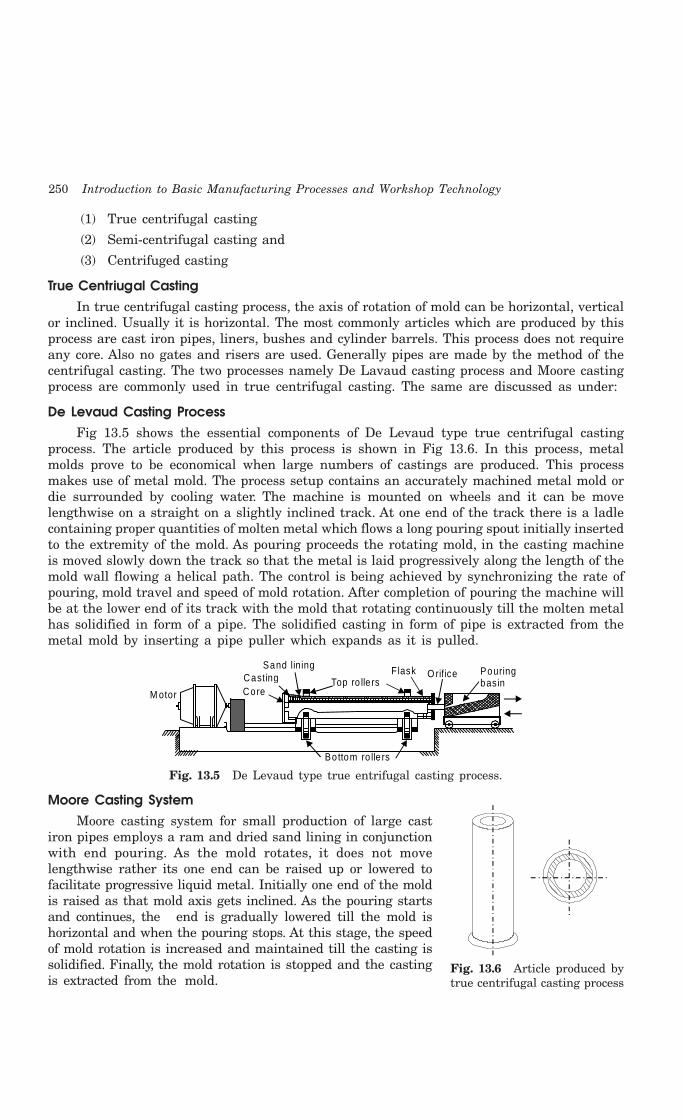
250 Introduction to Basic Manufacturing Processes and Workshop Technology
(1) True centrifugal casting
(2) Semi-centrifugal casting and
(3) Centrifuged casting
True Centriugal CastingIn true centrifugal casting process, the axis of rotation of mold can be horizontal, vertical
or inclined. Usually it is horizontal. The most commonly articles which are produced by thisprocess are cast iron pipes, liners, bushes and cylinder barrels. This process does not requireany core. Also no gates and risers are used. Generally pipes are made by the method of thecentrifugal casting. The two processes namely De Lavaud casting process and Moore castingprocess are commonly used in true centrifugal casting. The same are discussed as under:
De Levaud Casting ProcessFig 13.5 shows the essential components of De Levaud type true centrifugal casting
process. The article produced by this process is shown in Fig 13.6. In this process, metalmolds prove to be economical when large numbers of castings are produced. This processmakes use of metal mold. The process setup contains an accurately machined metal mold ordie surrounded by cooling water. The machine is mounted on wheels and it can be movelengthwise on a straight on a slightly inclined track. At one end of the track there is a ladlecontaining proper quantities of molten metal which flows a long pouring spout initially insertedto the extremity of the mold. As pouring proceeds the rotating mold, in the casting machineis moved slowly down the track so that the metal is laid progressively along the length of themold wall flowing a helical path. The control is being achieved by synchronizing the rate ofpouring, mold travel and speed of mold rotation. After completion of pouring the machine willbe at the lower end of its track with the mold that rotating continuously till the molten metalhas solidified in form of a pipe. The solidified casting in form of pipe is extracted from themetal mold by inserting a pipe puller which expands as it is pulled.
M otor
Sand lining Casting Core
Top ro lle rsFlask O rifice
Bottom ro lle rs
Pouringbasin
Fig. 13.5 De Levaud type true entrifugal casting process.
Moore Casting SystemMoore casting system for small production of large cast
iron pipes employs a ram and dried sand lining in conjunctionwith end pouring. As the mold rotates, it does not movelengthwise rather its one end can be raised up or lowered tofacilitate progressive liquid metal. Initially one end of the moldis raised as that mold axis gets inclined. As the pouring startsand continues, the end is gradually lowered till the mold ishorizontal and when the pouring stops. At this stage, the speedof mold rotation is increased and maintained till the casting issolidified. Finally, the mold rotation is stopped and the castingis extracted from the mold.
Fig. 13.6 Article produced bytrue centrifugal casting process

Casting 251
Semi-Centrifugal CastingIt is similar to true centrifugal casting but only with a difference that a central core is usedto form the inner surface. Semi- centrifugal casting setup is shown in Fig. 13.7. This castingprocess is generally used for articles which are more complicated than those possible in truecentrifugal casting, but are axi-symmetric in nature. A particular shape of the casting isproduced by mold and core and not by centrifugal force. The centrifugal force aids properfeeding and helps in producing the castings free from porosity. The article produced by thisprocess is shown in Fig. 13.8. Symmetrical objects namely wheel having arms like flywheel,gears and back wheels are produced by this process.
Centre core
Pouring basinStrainer core
Feeder reservo ir
Casting
Cope
FlaskDrag
Ho ld ingfixture
Revo lv ing tab le
Fig. 13.7 Semi-centrifugal casting setup
Centrifuging CastingCentrifuging casting setup is shown in Fig. 13.9. This casting process is generally used
for producing non-symmetrical small castings having intricate details. A number of such smalljobs are joined together by means of a common radial runner with a central sprue on a tablewhich is possible in a vertical direction of mold rotation. The sample article produced by thisprocess is depicted in Fig. 13.10.
13.9 CONTINNOUS CASTING
In this process the molten metal is continuously poured in to a mold cavity around whicha facility for quick cooling the molten metal to the point of solidification. The solidified metalis then continuously extracted from the mold at predetermined rate. This process is classifiedinto two categories namely Asarco and Reciprocating. In reciprocating process, molten metalis poured into a holding furnace. At the bottom of this furnace, there is a valve by which thequantity of flow can be changed. The molten metal is poured into the mold at a uniformspeed. The water cooled mold is reciprocated up and down. The solidified portion of thecasting is withdrawn by the rolls at a constant speed. The movement of the rolls and thereciprocating motion of the rolls are fully mechanized and properly controlled by means ofcams and follower arrangements.
Advantages of Continuous Casting
(i) The process is cheaper than rolling
Fig. 13.8 Article produced by semi-centrifugal casting process

252 Introduction to Basic Manufacturing Processes and Workshop Technology
Central sprue
Central sp rueCore
Cope
Casting
D rag
Partingline
Fig. 13.9 Centrifuging casting setup
(ii) 100% casting yield.
(iii) The process can be easily mechanized and thus unit labor cost is less.
(iv) Casting surfaces are better.
(v) Grain size and structure of the casting can be easily controlled.
Applications of Continuous Casting
(i) It is used for casting materials such as brass, bronzes, zinc, copper, aluminium andits alloys, magnesium, carbon and alloys etc.
(ii) Production of blooms, billets, slabs, sheets, copper bar etc.
(iii) It can produce any shape of uniform cross-section such as round, rectangular, square,hexagonal, fluted or gear toothed etc.
13.10 PROBABLE CAUSES AND SUGGESTED REMEDIES OF VARIOUS CASTING DEFECTS
The probable causes and suggested remedies of various casting defects is given in Table 13.1.
Fig. 13.10 Article produced bycentrifuging casting process

Casting 253
Table 13.1: Probable Causes and Suggested Remedies of Various Casting Defects
S.No. Name of Probable Causes Suggested RemediesCastingDefect
1. Blow holes 1. Excess moisture content in 1. Control of moisture content.molding sand.
2. Rust and moisture on Chills, 2. Use of rust free chills, chapletchaplets and inserts and clean inserts.
3. Cores not sufficiently baked. 3. Bake cores properly.
4. Excessive use of organic binders. 4. Ram the mold s less hard.
5. Molds not adequately vented. 5. Provide adequate venting in
6. Molds not adequately vented. mold and cores
7. Molds rammed very hard.
2. Shrinkage 1. Faulty gating and risering system. 1. Ensure proper directionalsolidification by modifying gating,
2. Improper chilling. risering and chilling
3. Porosity 1. High pouring temperature. 1. Regulate pouring temperature
2. Gas dissolved in metal charge. 2. Control metal composition.
3. Less flux used. 3. Increase flux proportions.
4. Molten metal not properly degassed. 4. Ensure effective degassing.
5. Slow solidification of casting. 5. Modify gating and risering.
6. High moisture and low permeability 6. Reduce moisture and increasein mold. permeability of mold.
4. Misruns 1. Lack of fluidity ill molten metal. 1. Adjust proper pouring temperature.
2. Faulty design. 2. Modify design.
3. Faulty gating. 3. Modify gating system.
5. Hot Tears 1. Lack of collapsibility of core. 1. Improve core collapsibility.
2. Lack of collapsibility of mold 2. Improve mold collapsibility.
3. Faulty design. 3. Modify casting design.
4. Hard Ramming of mold. 4. Provide softer ramming.
6. Metal 1. Large grain size and used. 1. Use sand having finer grain size.
penetration 2. Soft ramming of mold. 2. Provide hard ramming.
3. Molding sand or core has low strength. 3. Suitably adjust pouring temperature.
4. Molding sand or core has high permeability.
5. Pouring temperature of metal too high.7. Cold shuts 1. Lack of fluidity in molten metal. 1. Adjust proper pouring temperature.
2. Faulty design. 2. Modify design.3. Faulty gating. 3. Modify gating system
8. Cuts and 1. Low strength of mold and core. 1. Improve mold and core strength.washes 2. Lack of binders in facing and core 2. Add more binders to facing and
stand. core sand.3. Faulty gating. 3. Improve gating

254 Introduction to Basic Manufacturing Processes and Workshop Technology
9. Inclusions 1. Faulty gating. 1. Modify gating system
2. Faulty pouring. 2. Improve pouring to minimizeturbulence.
3. Inferior molding or core sand. 3. Use of superior sand of goodstrength.
4. Soft ramming of mold. 4. Provide hard, ramming.
5. Rough handling of mold and core.
10. Fusion 1. Low refractoriness in molding sand 1. Improve refractoriness of sand.
2. Faulty gating. 2. Modify gating system.
3. Too high pouring temperature of metal. 3. Use lower pouring temperature.
4. Poor facing sand. 4. Improve quality of facing sand.
11. Drops 1. Low green strength in molding sand 1. Increase green strength of sandand core. mold.
2. Too soft ramming. 2. Provide harder ramming.
3. Inadequate reinforcement of sand 3. Provide adequate reinforcement toand core projections sand projections and cope by using
nails and gaggers.
12. Shot Metal 1. Too low pouring temperature. 1. Use proper pouring temperature.
2. Excess sulphur content in metal. 2. Reduce sulphur content.
3. Faulty gating. 3. Modify gating of system.
4. High moisture content in molding sand.
13. Shift 1. Worn-out or bent clamping pins. 1. Repair or replace the pins, forremoving defect.
2. Misalignment of two halves of pattern. 2. Repair or replace dowels whichcause misalignment.
3. Improper support of core. 3. Provide adequate support to core.
4. Improper location of core. 4. Increase strength of both mold
5. Faulty core boxes. and core
6. Insufficient strength of molding sandand core.
14. Crushes 1. Defective core boxes producing 1. Repair or replace the pins,over-sized cores. for removing defect.
2. Worn out core prints on patterns 2. Repair or replace dowels whichproducing under sized seats for cores cause misalignment.in the mold.
3. Careless assembly of cores in the mold 3. Provide adequate support to core.
4. Increase strength of both moldand core.
15. Rat-tails or 1. Continuous large flat surfaces on 1. Break continuity of large flat grovesBuckles casting. and depressions
2. Excessive mold hardness. 2. Reduce mold hardness.
3. Lack of combustible additives in 3. Add combustible additives to sand.molding sand.

Casting 255
16. Swells 1. Too soft ramming of mold. 1. Provide hard ramming.
2. Low strength of mold and core 2. Increase strength of both mold
3. Mold not properly supported. and core.
17. Hard Spot 1. Faulty metal composition. 1. Suitably charge metal composition.
2. Faulty casting design. 2. Modify casting design.
18. Run out, Fins 1. Faulty molding. 1. Improving molding technique.
and Fash 2. Defective molding boxes. 2. Change the defective molding boxes.
3. Keep weights on mold boxes.
19. Spongings 1. Availability of dirt and swarf held 1. Remove dirt swarf held in moltenin molten metal. metal.
2. Improper skimming. 2. Skimming should be perfect.
3. Because of more impurities in 3. Fewer impurities in molten metalmolten metal should be there.
20. Warpage 1. Continuous large flat surfaces on 1. Follow principle of sufficientcastings indicating a poor design. directional solidification
2. No directional solidification of casting. 2. Make good casting design
13.11 PLASTICS MOLDING PROCESSES
There are various methods of producing components from the plastics materials which aresupplied in the granular, powder and other forms. Various plastics molding processes are:
1. Compression Molding.2. Transfer Molding3. Injection Molding.4. Blow Molding.5. Extrusion Molding6. Calendaring.7. Thermoforming.8. Casting
Two major processes from the above are discussed as under.
13.11.1 Injection die MoldingIn this process, thermoplastic materials soften when heated and re-harden when cooled. Nochemical change takes place during heating and cooling. Fig. 13.11 illustrates the injectionmolding process. The process involves granular molding material is loaded into a hopper fromwhere it is metered out in a heating cylinder by a feeding device. The exact amount ofmaterial is delivered to the cylinder which is required to fill the mold completely. Theinjection ram pushes the material into a heating cylinder and doing so pushing bushes a smallamount of heated material out of other end of cylinder through the nozzle and screw bushingand into cavities of the closed mold. The metal cooled in rigid state in the mold. Then moldis opened and piece is ejected out material heating temperature is usually between 180°-280°C. Mold is cooled in order to cool the mold articles. Automatic devices are commerciallyavailable to maintain mold temperature at required level. Injection molding is generallylimited to forming thermoplastic materials, but equipment is available for converting themachines for molding thermosetting plastics and compounds of rubber.
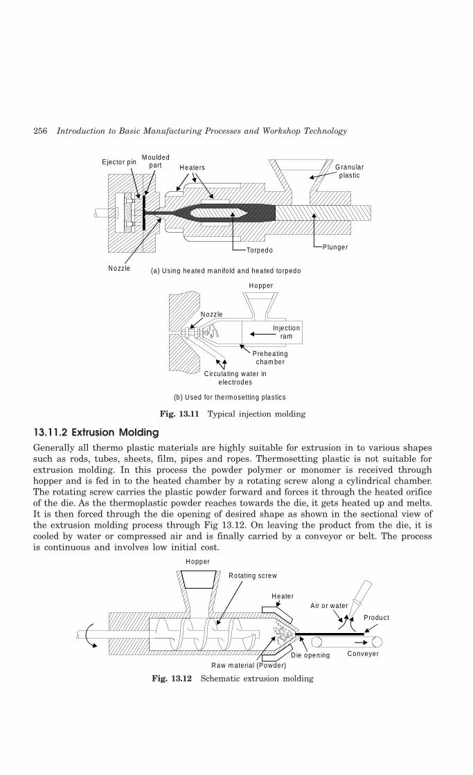
256 Introduction to Basic Manufacturing Processes and Workshop Technology
Hopper
Nozzle
In jectionram
Preheatingcham ber
C ircu la ting water ine lectrodes
(b) Used fo r thermosetting plastics
E jecto r p in M ou lded
part Heaters G ranu la rp lastic
P lungerTorpedo
(a) Using heated m an ifo ld and hea ted to rpedoNozzle
Fig. 13.11 Typical injection molding
13.11.2 Extrusion MoldingGenerally all thermo plastic materials are highly suitable for extrusion in to various shapessuch as rods, tubes, sheets, film, pipes and ropes. Thermosetting plastic is not suitable forextrusion molding. In this process the powder polymer or monomer is received throughhopper and is fed in to the heated chamber by a rotating screw along a cylindrical chamber.The rotating screw carries the plastic powder forward and forces it through the heated orificeof the die. As the thermoplastic powder reaches towards the die, it gets heated up and melts.It is then forced through the die opening of desired shape as shown in the sectional view ofthe extrusion molding process through Fig 13.12. On leaving the product from the die, it iscooled by water or compressed air and is finally carried by a conveyor or belt. The processis continuous and involves low initial cost.
Hopper
Rotating screw
Heater A ir o r water
Product
D ie open ing Conveyer
Raw m aterial (Powder)
Fig. 13.12 Schematic extrusion molding

Casting 257
13.12 QUESTIONS1. Describe in detail the terms ‘solid zone’, ‘mushy zone’ and ‘liquid zone’ used in solidification
of castings. Using figures explain the term directional solidification used in castings.
2. What is “directional solidification”, and what is its influence on casting quality?
3. Is directional solidification is necessary in casting? How does it help in the production ofsound castings?
4. What are the controlling factors of directional solidification in casting? Name different stagesthrough which the metal contraction takes place during the solidification of the casting?
5. Why do you prefer fabricating of metal parts by casting?
6. Define casting. What four basic steps are generally involved in making a casting?
7. What are the common factors which should be considered before designing a casting?
8. Sketch the cross-section through a permanent mold, incorporating all its principal parts.Describe its construction in detail.
9. Describe the permanent mold casting process and discuss how it differs from the othercasting processes.
10. What are the common materials used for making the permanent molds?
11. Describe step by step procedure for casting using a permanent mold. What are the advantages,dis-advantages and applications of permanent mold casting?
12. What different metals and alloys are commonly cast in permanent molds?
13. What is the difference between gravity die casting and pressure die casting?
14. How are die casting machines classified? What are the common constructional featuresembodied in most of them?
15. Sketch and explain the construction and operation of a hot chamber die casting machine.
16. How does a cold chamber die casting machine differ from a hot chamber machine? Explainthe working of a cold chamber machine with the help of a diagram.
17. Make a neat sketch to explain the principal parts of an air blown or goose neck type machine.How does it differ from a hot chamber die casting machine. Discuss their relative advantages,disadvantages and applications.
18. What is a vacuum die-casting machine? How is the vacuum applied to hot and cold chambermachines to evacuate the entrapped air completely. What is the main advantage of this typeof machine?
19. Specify features required to be embodied in a successful design of a die-casting die.
20. Describe the various alloys commonly cast through pressure die-casting.
21. What are the general advantages, disadvantages applications of die casting?
22. How does a cold chamber die casting machine differ from a hot chamber die casting machine?
23. Make neat sketch and explain the construction and operation of a hot chamber die castingmachine.
24. Make neat sketch and explain the construction and operation of a cold chamber die castingmachine.
25. Explain the various steps involved in the investment casting of metals.
26. What is investment casting? What are the main materials used for making the investmentpattern?
27. Describe the complete step by step procedure of investment casting. What are the mainadvantages and disadvantages of investment casting?
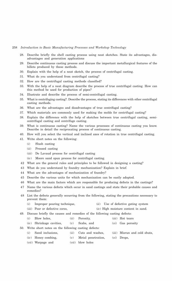
258 Introduction to Basic Manufacturing Processes and Workshop Technology
28. Describe briefly the shell casting process using neat sketches. State its advantages, dis-advantages and generation applications
29. Describe continuous casting process and discuss the important metallurgical features of thebillets produced by these methods.
30. Explain with the help of a neat sketch, the process of centrifugal casting.
31. What do you understand from centrifugal casting?
32. How are the centrifugal casting methods classified?
33. With the help of a neat diagram describe the process of true centrifugal casting. How canthis method be used for production of pipes?
34. Illustrate and describe the process of semi-centrifugal casting.
35. What is centrifuging casting?. Describe the process, stating its differences with other centrifugalcasting methods.
36. What are the advantages and disadvantages of true centrifugal casting?
37. Which materials are commonly used for making the molds for centrifugal casting?
38. Explain the difference with the help of sketches between true centrifugal casting, semi-centrifugal casting and centrifuge casting.
39. What is continuous casting? Name the various processes of continuous casting you know.Describe in detail the reciprocating process of continuous casting.
40. How will you select the vertical and inclined axes of rotation in true centrifugal casting.
41. Write short notes on the following:
(i) Slush casting
(ii) Pressed casting
(iii) De Lavaud process for centrifugal casting
(iv) Moore sand spun process for centrifugal casting.
42 What are the general rules and principles to be followed in designing a casting?
43 What do you understand by foundry mechanization? Explain in brief.
44 What are the advantages of mechanization of foundry?
45 Describe the various units for which mechanization can be easily adopted.
46 What are the main factors which are responsible for producing defects in the castings?
47 Name the various defects which occur in sand castings and state their probable causes andremedies?
48 List the defects generally occurring from the following, stating the precautions necessary toprevent them:
(i) Improper pouring technique, (ii) Use of defective gating system
(iii) Poor or defective cores, (iv) High moisture content in sand.
49. Discuss briefly the causes and remedies of the following casting defects:
(i) Blow holes, (ii) Porosity, (iii) Hot tears
(iv) Shrinkage cavities, (v) Scabs, and (vi) Gas porosity
50. Write short notes on the following casting defects:
(i) Sand inclusions, (ii) Cuts and washes, (iii) Misrun and cold shuts,
(iv) Honey combing, (v) Metal penetration, (vi) Drops,
(vii) Warpage and (vii) blow holes

Casting 259
51. Explain the causes and remedies of the following casting defects:
(i) Fins (ii) Shot metal
(iii) Shifts (iv) Hard spots
(v) Run out (vi) Rattails or buckles
(vii) Fusion (viii) Swells
(ix) Crushes
52. What are the various operations generally required to be performed after shake out forcleaning the castings?
53. Explain the various methods used for removal of gates and risers etc.
54. What are the common methods used for cleaning the surface of the casting?
55. Why are the castings heat treated?
56. How do you repair the castings? Explain.
57. What do you understand from destructive and non-destructive testing methods of inspectingcastings?
58. What are the various non-destructive testing methods used for inspection of castings? Statetheir advantages and limitations:
59. Write short notes on the following inspection methods:
(i) Visual inspection
(ii) Pressure test
(iii) Penetrate testing
(iv) Radiography
(v) Magnetic particle testing
(vi) Ultrasonic testing.

260 Introduction to Basic Manufacturing Processes and Workshop Technology
260
FORGING
14.1 INTRODUCTION
Forging is an oldest shaping process used for the producing small articles for which accuracyin size is not so important. The parts are shaped by heating them in an open fire or hearthby the blacksmith and shaping them through applying compressive forces using hammers.Thus forging is defined as the plastic deformation of metals at elevated temperatures into apredetermined size or shape using compressive forces exerted through some means of handhammers, small power hammers, die, press or upsetting machine. It consists essentially ofchanging or altering the shape and section of metal by hammering at a temperature of about980°C, at which the metal is entirely plastic and can be easily deformed or shaped underpressure. The shop in which the various forging operations are carried out is known as thesmithy or smith’s shop. A metal such as steel can be shaped in a cold state but the applicationof heat lowers the yield point and makes permanent deformation easier. Forging operationcan be accomplished by hand or by a machine hammer. Forging processes may be classifiedinto hot forging and cold forgings and each of them possesses their specific characteristics,merits, demerits and applications.
Hand forging process is also known as black-smithy work which is commonly employedfor production of small articles using hammers on heated jobs. It is a manual controlledprocess even though some machinery such as power hammers can also be sometimes used.Black-smithy is, therefore, a process by which metal may be heated and shaped to itsrequirements by the use of blacksmith tools either by hand or power hammer. In smithysmall parts are shaped by heating them in an open fire or hearth. Shaping is done under handcontrol using hand tools. This work is done in a smithy shop. In smith forging or hand forgingopen face dies are used and the hammering on the heated metal is done by hand to get thedesired shape by judgment.
Forging by machine involves the use of forging dies and is generally employed for mass-production of accurate articles. In drop forging, closed impression dies are used and there isdrastic flow of metal in the dies due to repeated blow or impact which compels the plasticmetal to conform to the shape of the dies. The final shape of the product from raw materialis achieved in a number of steps. There are some advantages, disadvantages and applicationsof forging operations which are given as under.
14CHAPTER
Forging 261
Advantages of forgingSome common advantages of forging are given as under.
1. Forged parts possess high ductility and offers great resistance to impact and fatigueloads.
2. Forging refines the structure of the metal.
3. It results in considerable saving in time, labor and material as compared to theproduction of similar item by cutting from a solid stock and then shaping it.
4. Forging distorts the previously created unidirectional fiber as created by rolling andincreases the strength by setting the direction of grains.
5. Because of intense working, flaws are rarely found, so have good reliability.
6. The reasonable degree of accuracy may be obtained in forging operation.
7. The forged parts can be easily welded.
Disadvantages of forgingFew dis-advantages of forging are given as under.
1. Rapid oxidation in forging of metal surface at high temperature results in scalingwhich wears the dies.
2. The close tolerances in forging operations are difficult to maintain.
3. Forging is limited to simple shapes and has limitation for parts having undercutsetc.
4. Some materials are not readily worked by forging.
5. The initial cost of forging dies and the cost of their maintenance is high.
6. The metals gets cracked or distorted if worked below a specified temperature limit.
7. The maintenance cost of forging dies is also very high.
Applications of forgingAlmost all metals and alloys can be forged. The low and medium carbon steels are readilyhot forged without difficulty, but the high-carbon and alloy steels are more difficult to forgeand require greater care. Forging is generally carried out on carbon alloy steels, wroughtiron, copper-base alloys, alumunium alloys, and magnesium alloys. Stainless steels, nickel-based super-alloys, and titanium are forged especially for aerospace uses.
Producing of crank shaft of alloy steel is a good example which is produced by forging.Forging processes are among the most important manufacturing techniques utilized widelyin manufacturing of small tools, rail-road equipments, automobiles and trucks and componentsof aeroplane industries. These processes are also extensively used in the manufacturing ofthe parts of tractors, shipbuilding, cycle industries, railroad components, agriculturalmachinery etc.
14.2 FORGEABILITY
The ease with which forging is done is called forgeability. The forgeability of a material canalso be defined as the capacity of a material to undergo deformation under compressionwithout rupture. Forgeability increases with temperature up to a point at which a second

262 Introduction to Basic Manufacturing Processes and Workshop Technology
phase, e.g., from ferrite to austenite in steel, appears or if grain growth becomes excessive.The basic lattice structure of metals and their alloys seems to be a good index to their relativeforgeability. Certain mechanical properties are also influenced by forgeability. Metals whichhave low ductility have reduced forgeability at higher strain rate whereas highly ductilemetals are not so strongly affected by increasing strain rates. The pure metals have goodmalleability and thus good forging properties. The metals having high ductility at cold workingtemperature possesses good forgeability.
Cast parts, made up of cast iron are brittle, and weak in tension, though they arestrong in compression. Such parts made using cast iron tend to need to be bulky and areused where they will not be subjected to high stresses. Typical examples are machine bases,cylinder blocks, gear-box housings etc. Besides the above factors, cost is another majorconsideration in deciding whether to cast a component or to forge it. An I.C. engine connectingrod is a very good example of where a forging will save machining time and material,whereas the cylinder block of the same engine would be very expensive if produced by anyprocess other than casting. Another good point associated with casting is that big or smallcomplex shapes can easily be cast. Small parts can directly be machined out from regularsection materials economically. A part machined out from the rolled steel stock definitelypossesses better mechanical properties than a conventionally cast part. Sometimes theshape and size of a part would mean removing a large amount of material by machining,it is sometimes more economical to forge the part, thereby reducing the machining timeand the amount of material required.
The main alloys for cold forging or hot forging are most aluminium and copperalloys, including the relatively pure metals. Carbon steels with 0.25 % carbon or less arereadily hot forged or cold-headed. High carbon and high alloy steels are almost alwayshot forged. Magnesium possessing hexagonal close packed (HCP) structure has littleductility at room temperature but is readily hot forged. Aluminium alloys are forgedbetween 385°C and 455°C or about 400°C below the temperature of solidification. Aluminiumalloys do not form scale during hot forging operations, die life is thus excellent. Copperand brasses with 30% or less zinc have excellent forgeability in cold working operations.High zinc brasses can be cold forged to a limited extent but are excellent hot forgingalloys. Magnesium alloys are forged on presses at temperature above 400°C. At highertemperatures, magnesium must be protected from oxidation or ignition by an inertatmosphere of sulphur dioxide.
14.3 FORGABLE MATERIALS
Two-phase and multi-phase materials are deformable if they meet certain minimumrequirements. The requirement of wrought metals is satisfied by all pure metals withsufficient number of slip planes and also by most of the solid solution alloys of the samemetal. Wrought alloys must possess a minimum ductility that the desired shape shouldpossess. To be a forgeable metal, it should possess the required ductility. Ductility refersto the capacity of a material to undergo deformation under tension without rupture.Forging jobs call for materials that should possess a property described as ductility thatis, the ability to sustain substantial high plastic deformation without fracture even inthe presence of tensile stresses. If failure occurs during forging, it is due to the mechanismof ductile fracture and is induced by tensile stresses. A material of a given ductility mayfail very differently in various processes, depending on the deforming conditions imposed

Forging 263
on it. Forgeable metals are purchased as hot-rolled bars or billets with round orrectangular cross the sections. Forgeable materials should possess the required ductilityand proper strength. Some forgeable metals are given as under in order of increasingforging difficulty.
1. Aluminium alloys 2. Magnesium alloys
3. Copper alloys. 4. Carbon and low alloy steels
5. Martensitic stainless steels 6. Austenitic stainless steels
7. Nickel alloys 8. Titanium alloys
9. Columbium alloys 10. Tantalum alloys
11. Molybdenum alloys 12. Tungsten alloys
13. Beryllium.
14.4 HEATING DEVICES
Forgeable metals are heated either ina hearth or in a furnace. The hearthsare widely used for heating the metalsfor carrying out hand forging operations.Furnaces are also commonly used forheating metals for heavy forging. Theforging job is always heated to thecorrect forging temperature in a hearth(Fig. 14.1) or in a furnace (Fig. 14.2)located near the forging arrangements.Gas, oil or electric-resistance furnacesor induction heating classified as openor closed hearths can be used. Gas andoil are economical, easily controlled andmostly used as fuels. The formation ofscale, due to the heating processespecially on steel creates problems inforging. A non-oxidizing atmosphereshould, therefore, be maintained forsurface protection. Special gas-firedfurnaces have been developed to reducescaling to minimum. Electric heating isthe most modern answer to tackle scalingand it heats the stock more uniformly also. In some cases, coal and anthracite, charcoalcontaining no sulphur and practically no ash are the chief solid fuels used in forging furnaces.Forge furnaces are built raise temperatures up to 1350°C in their working chambers. Theyshould be sufficiently large to allow proper combustion of the fuel, and to obtain uniformheating of the forging jobs. Each heating furnace consists of parts including firebox, workingchamber, chimney, flues, re-cuperator or regenerator, and various auxiliary arrangements.Various types of furnaces are used for heating the metals and some of them are brieflydescribed as under.
Hood
Watertank
Tuyere
Hearth
Fig. 14.1 Typical hearth

264 Introduction to Basic Manufacturing Processes and Workshop Technology
M etal to be hea ted
Bed
C linker
Tuyere
Fig. 14.2 Black smith furnace
14.4.1 Box or batch type furnacesThese furnaces are the least expensive furnaces widely used in forging shops for heatingsmall and medium size stock. There is a great variety of design of box-type furnaces, eachdiffering in their location of their charging doors, firing devices and method, employed for.charging their products. These furnaces are usually constructed of a rectangular steel frame,lined with insulating and refractory bricks. One or more burners for gas or oil can be providedon the sides. The job-pieces are placed side by side in the furnace using a slot through asuitable tong. It is therefore sometimes called slot type furnace.
14.4.2 Rotary-hearth furnacesThese are set to rotate slowly so that the stock is red to the correct temperature during onerotation. These can be operated by gas or oil fuels.
14.4.3 Continuous or conveyor furnacesThese furnaces are of several types and are preferred for larger stock. They have an air oroil-operated cylinder to push stock end-to-end through a narrow furnace. The pieces arecharged at one end, conveyed through the furnace and moved at other end at the correcttemperature for the forging work.
14.4.4 Induction furnacesThese furnaces are very popular because induction greatly decreases scale formation and canoften be operated by one person. The furnace requires less maintenance than oil or gas-firedfurnaces. In induction furnaces the stocks are passed through induction coils in the furnaces.Delivery to forging machine operator can be effected by slides or automatic handling equipment.
14.4.5 Resistance furnacesThese furnaces are faster than induction furnaces, and can be automated easily. In resistanceheating furnace, the stock is connected to the circuit of a step-down transformer. Fixturesare also equipped along with furnace for holding different length, shape, and diameter ofstock. However, the fixtures are often quite simple and can be adjusted to handle a familyof parts.

Forging 265
14.4.6 Open fire and stock fire furnaceThe fire itself plays an important part on the efficient heating of stock and it must be keptclean, free from excess dust or clinkers. Work which is laid on top of the fire will get hotunderneath and remain colder on the top use it is exposed to the atmosphere, and unevenheating will result. In the same way, work which is red low in the fire but at the same timeagainst the tuyre will become hot on one side, but will have a blast of clod air blowing againstit, from the tuyre on the other side. The correct position for heating the job is in the hearthof the fire. The most common methods of firing in forging are namely open fire and stockfire which are discussed as under.
Open fireOpen fire is shown in Fig.14.3. This type
of fire is highly convenient for general heatingwork and is made up in the hollow space infront of tuyre nozzle with coke left from thelast fire, covered with green petroleum. As thefire burns away, coke from the top and sides isdrawn into the centre, and its place is taken bymore green coal taken from the supplymaintained on the front place of the forge ortaken from the outside. The jobs or work-piecesmust be covered with a layer of coal, and toobtain a flame at single spot, the coal shouldbe slightly damped with water and pressed downwith a flat shovel. In the spot where the flameis desired, the coal should be loosened with apocker. To ensure uniform heating of work on allsides, it must be turned round from time to time.
Stock fire
A stock fire is depicted through Fig.14.4which is intended to last for several hours. Thistype of fire is commonly useful in dealing withlarge pieces, when a heat may have to be keptfor sometime. The job or work has to be turnedin all directions to ensure uniform heating ofthe job. Such fire is made up around a block ofthe desired size which is placed near the tuyernozzle and upon which coal damped with waterthat is closely built into the form of a moundor “stock”. Fine coal or pulverized coal issuitable for use in stock fire. The block is thenwithdrawn from the bed of the hearth with aturning force to prevent the stock from being broken and a tunnel is thus formed with anopening at the top. The fire is then lighted in the hollow space. From the bottom of the tunnela small amount of coal is removed and a cavity is formed in the place in to which clinker mayfall. Here the work is heated, being carefully covered with freshly coke fuel from time to timeas the fire burns away.
Air
Fig. 14.3 Open fire
Fig. 14.4 Stock fire

266 Introduction to Basic Manufacturing Processes and Workshop Technology
14.4.7 Fuels used in forging shopThe fuels used in forging shop are classified as solid, liquid and gaseous fuels which arediscussed as under.
Solid fuelsWood, coal, anthracite, peat, charcoal, coke, pulverized fuel etc.
Liquid fuelsCrude oil, petroleum, kerosene, tar oil etc.
Gaseous fuelsNatural gas and some artificially produced gases are used generate heat.
A good fuel should have always possesses the following essential characteristic which aregiven as under.
1. The fuel should be able to generate the required heat.
2. It should have complete combustion.
3. It should be highly efficient.
4. It should not produce excess smoke and flying ash.
5. It should be easy to fire, cheap and easily available.
14.5 CONTROL OF HEATING DEVICES
For good control of heating devices such as hearth or forging furnace, the following pointsare should always be considered.
1. The nozzle pointing into the centre of the hearth is called the tuyre and is used todirect a stream of air into the burning coke. The air is supplied by centrifugal blower.
2. As the hottest part of the fire is close to the tuyre opening, therefore, the tuyre isprovided with a water jacket to prevent it from burning away.
3. The hood provided at the top of hearth collects smoke, fumes etc., and directs themaway from the workplace through the chimney in form of exhaust.
4. The fuel for the fire may be either black-smithing coal or coke. To light the fire,either use paper and sticks or preferably a gas poker.
5. Impurities will collect as clinker and must be removed from the bottom of the firewhen the fire cools.
6. The blowers are used to control the air supply using forced draught. Regulatorscontrol the draught and the temperature of the fire.
7. Blower delivers to forge adequate supply of air at proper pressure which is verynecessary for the combustion of fuel.
8. A centrifugal blower driven by an electric motor is an efficient means of air supplyin forging hearth.
9. Fire tools such as rake, poker and slice are generally used to control or manage thefire and theses tools are kept nearby the side of the hearth. Rake is used to takeheated workpiece out of the fire. Poker is a steel rod which is used to poke (stir)fire in the hearth.
Forging 267
10. The place of the metal to be heated should be placed just above the compact centreof a sufficiently large fire with additional fuel above to reduce the heat loss andatmospheric oxidation.
14.6 FORGING TEMPERATURES
A metal must be heated to a temperature at which it will possess high plastic properties tocarry out the forging process. The metal work piece is heated to a proper temperature so thatit gains required plastic properties before deformation, which are essential for satisfactoryforging. Excessive temperatures may result in the burning of the metal. Insufficienttemperatures will not introduce sufficient plasticity in the metal to shape it properly byhammering etc. Moreover, under these conditions, the cold working defects such as hardeningand cracking may occur in the product.
The temperature to start the forging for soft, low carbon steels is 1,250 to 1,300°C, thetemperature to finish forging is 800 to 840°C. The corresponding temperatures for high carbonand alloy steels which are hard in nature are 1100 to l140°C and 830 to 870°C. Wrought ironis best forged at a temperature little below 1,290°C. Non ferrous alloys like bronze and brassare heated to about 600 to 930°C, the aluminium and magnesium alloys to about 340 to 500°C.
Forging temperature should be proper to get good results. Excessive temperature mayresult in the burning of the metal, which destroys the cohesion of the metal. Insufficienttemperature will not introduce sufficient plasticity in the metal. The forging operation in metalis if finished at a lower temperature, it may lead to cold hardening and cracks may develop init. However, excessive heating of the forgeable part may result in oxidization and hence materialis wasted. The temperature of heating steel for hand forging can be estimated by the color ofheat and which color of the light emitted by the heated steel. For accurate determinations offorging temperatures of the heated part, the optical pyrometers are generally used.
14.7 ADVANTAGES OF FORGING IN COMPARASION TO CASTING ANDMACHINING
Because of inherent improvement in the grain size and introduction of un-interrupted grainflow in the structure of finished forged component forging has the following advantages incomparison to casting and machining. Some of such advantages are given as under.
(i) Greater strength and toughness.
(ii) Reduction in weight of the finished part.
(iii) Saving in the material.
(iv) Elimination of internal defects such as cracks, porosity, blowholes, etc.
(v) Ability to withstand unpredictable loads during service.
(vi) Minimum of machine finish to be carried out on the component especially when itis forged in dies.
14.8 EFFECT OF FORGING ON METAL CHARACTERISTICS
Generally a forging material is selected based on certain desirable mechanical propertiesinherent in the composition and/or for those which can be developed by forging. Such propertiesmay be one or several, such as strength, resistance to fatigue, shock or bending, good
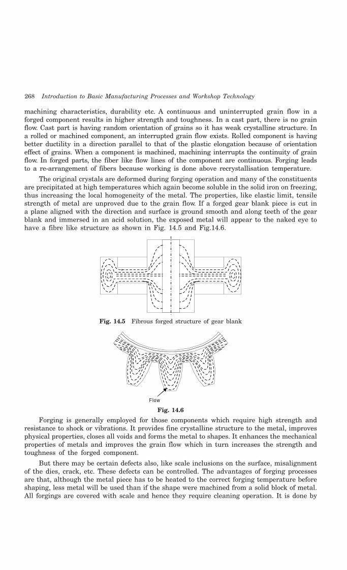
268 Introduction to Basic Manufacturing Processes and Workshop Technology
machining characteristics, durability etc. A continuous and uninterrupted grain flow in aforged component results in higher strength and toughness. In a cast part, there is no grainflow. Cast part is having random orientation of grains so it has weak crystalline structure. Ina rolled or machined component, an interrupted grain flow exists. Rolled component is havingbetter ductility in a direction parallel to that of the plastic elongation because of orientationeffect of grains. When a component is machined, machining interrupts the continuity of grainflow. In forged parts, the fiber like flow lines of the component are continuous. Forging leadsto a re-arrangement of fibers because working is done above recrystallisation temperature.
The original crystals are deformed during forging operation and many of the constituentsare precipitated at high temperatures which again become soluble in the solid iron on freezing,thus increasing the local homogeneity of the metal. The properties, like elastic limit, tensilestrength of metal are unproved due to the grain flow. If a forged gear blank piece is cut ina plane aligned with the direction and surface is ground smooth and along teeth of the gearblank and immersed in an acid solution, the exposed metal will appear to the naked eye tohave a fibre like structure as shown in Fig. 14.5 and Fig.14.6.
Fig. 14.5 Fibrous forged structure of gear blank
Flow
Fig. 14.6
Forging is generally employed for those components which require high strength andresistance to shock or vibrations. It provides fine crystalline structure to the metal, improvesphysical properties, closes all voids and forms the metal to shapes. It enhances the mechanicalproperties of metals and improves the grain flow which in turn increases the strength andtoughness of the forged component.
But there may be certain defects also, like scale inclusions on the surface, misalignmentof the dies, crack, etc. These defects can be controlled. The advantages of forging processesare that, although the metal piece has to be heated to the correct forging temperature beforeshaping, less metal will be used than if the shape were machined from a solid block of metal.All forgings are covered with scale and hence they require cleaning operation. It is done by
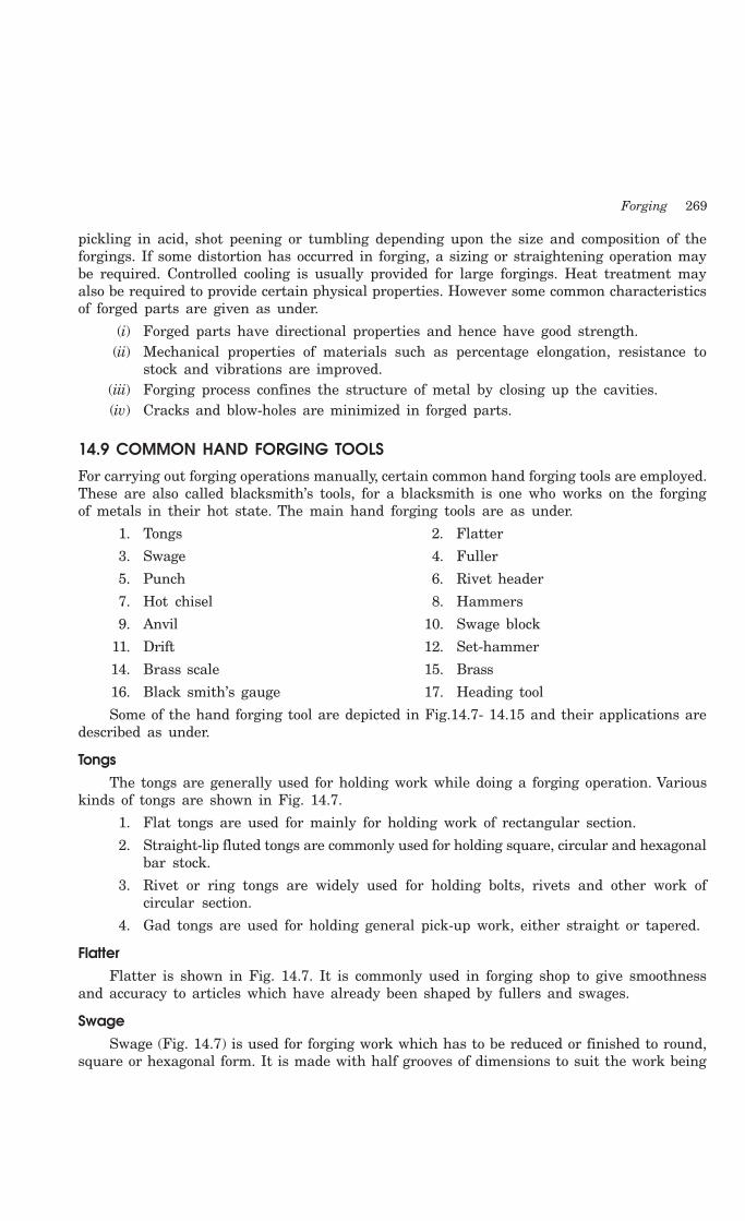
Forging 269
pickling in acid, shot peening or tumbling depending upon the size and composition of theforgings. If some distortion has occurred in forging, a sizing or straightening operation maybe required. Controlled cooling is usually provided for large forgings. Heat treatment mayalso be required to provide certain physical properties. However some common characteristicsof forged parts are given as under.
(i) Forged parts have directional properties and hence have good strength.(ii) Mechanical properties of materials such as percentage elongation, resistance to
stock and vibrations are improved.(iii) Forging process confines the structure of metal by closing up the cavities.(iv) Cracks and blow-holes are minimized in forged parts.
14.9 COMMON HAND FORGING TOOLS
For carrying out forging operations manually, certain common hand forging tools are employed.These are also called blacksmith’s tools, for a blacksmith is one who works on the forgingof metals in their hot state. The main hand forging tools are as under.
1. Tongs 2. Flatter
3. Swage 4. Fuller
5. Punch 6. Rivet header
7. Hot chisel 8. Hammers
9. Anvil 10. Swage block
11. Drift 12. Set-hammer
14. Brass scale 15. Brass
16. Black smith’s gauge 17. Heading tool
Some of the hand forging tool are depicted in Fig.14.7- 14.15 and their applications aredescribed as under.
TongsThe tongs are generally used for holding work while doing a forging operation. Various
kinds of tongs are shown in Fig. 14.7.
1. Flat tongs are used for mainly for holding work of rectangular section.
2. Straight-lip fluted tongs are commonly used for holding square, circular and hexagonalbar stock.
3. Rivet or ring tongs are widely used for holding bolts, rivets and other work ofcircular section.
4. Gad tongs are used for holding general pick-up work, either straight or tapered.
FlatterFlatter is shown in Fig. 14.7. It is commonly used in forging shop to give smoothness
and accuracy to articles which have already been shaped by fullers and swages.
SwageSwage (Fig. 14.7) is used for forging work which has to be reduced or finished to round,
square or hexagonal form. It is made with half grooves of dimensions to suit the work being

270 Introduction to Basic Manufacturing Processes and Workshop Technology
reduced. It consists of two parts, the top part having a handle and the bottom part havinga square shank which fits in the hardie hole on the anvil face.
FullerFuller (Fig. 14.7) is used in forging shop for necking down a forgeable job. It is made in
top and bottom tools as in the case of swages. Fuller is made in various shapes and sizesaccording to needs, the size denoting the width of the fuller edge
PunchPunch (Fig. 14.7) is used in forging shop for making holes in metal part when it is at
forging heat.
Flat tongs
Straigh t-lip flu ted tongs
Flat tongsG ad tongs
R ive t o r ring tongs
FlatterSwage
Fu ller
R ive t header
Punch
Hot chise l
Fig. 14.7 Hand forging tools
Rivet headerRivet header (Fig. 14.7) is used in forging shop for producing rivets heads on parts.
ChiselsChisels are used for cutting metals and for nicking prior to breaking. They may be hot
or cold depending on whether the metal to be cut is hot or cold. A hot chisel generally usedin forging shop is shown in Fig. 14.7. The main difference between the two is in the edge.The edge of a cold chisel is hardened and tempered with an angle of about 60°, whilst the edgeof a hot chisel is 30° and the hardening is not necessary. The edge is made slightly roundedfor better cutting action.
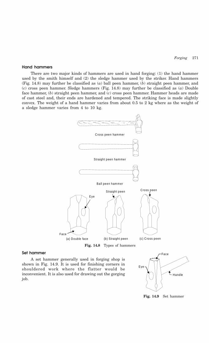
Forging 271
Hand hammersThere are two major kinds of hammers are used in hand forging: (1) the hand hammer
used by the smith himself and (2) the sledge hammer used by the striker. Hand hammers(Fig. 14.8) may further be classified as (a) ball peen hammer, (b) straight peen hammer, and(c) cross peen hammer. Sledge hammers (Fig. 14.8) may further be classified as (a) Doubleface hammer, (b) straight peen hammer, and (c) cross peen hammer. Hammer heads are madeof cast steel and, their ends are hardened and tempered. The striking face is made slightlyconvex. The weight of a hand hammer varies from about 0.5 to 2 kg where as the weight ofa sledge hammer varies from 4 to 10 kg.
Eye
(a ) Doub le face
Straigh t peen
Face
Cross peen
(b ) S traigh t peen (c) C ross peen
Ba ll peen ham m er
Straigh t peen ham mer
Cross peen ham mer
Fig. 14.8 Types of hammers
Set hammerA set hammer generally used in forging shop is
shown in Fig. 14.9. It is used for finishing corners inshouldered work where the flatter would beinconvenient. It is also used for drawing out the gorgingjob.
Face
Eye
Hand le
Fig. 14.9 Set hammer
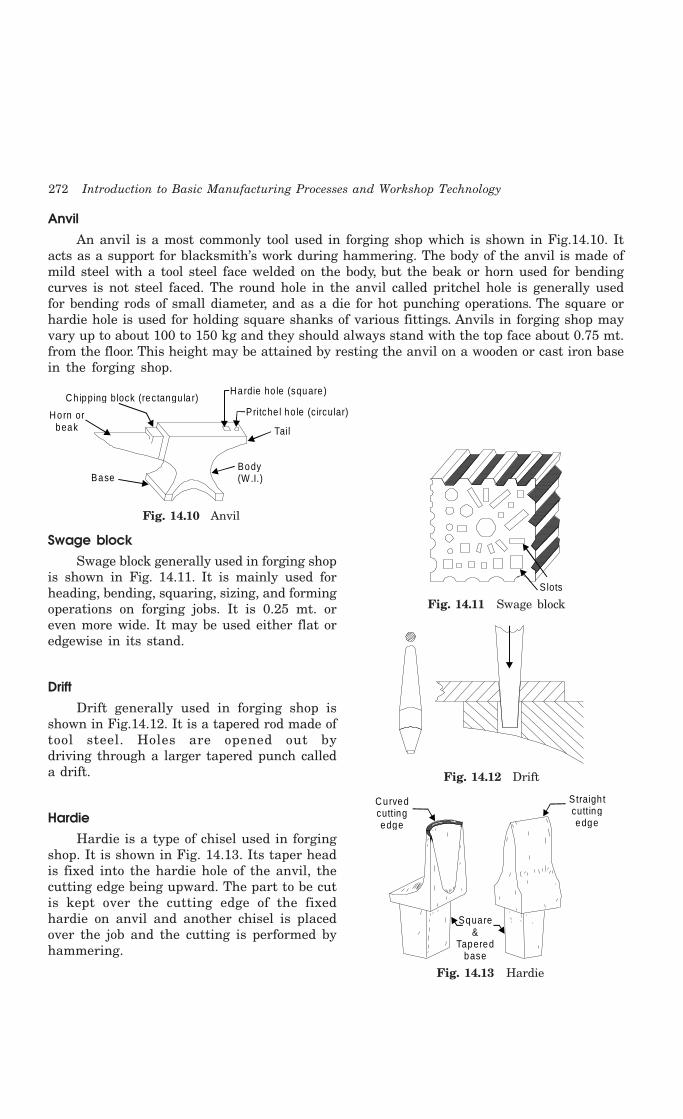
272 Introduction to Basic Manufacturing Processes and Workshop Technology
AnvilAn anvil is a most commonly tool used in forging shop which is shown in Fig.14.10. It
acts as a support for blacksmith’s work during hammering. The body of the anvil is made ofmild steel with a tool steel face welded on the body, but the beak or horn used for bendingcurves is not steel faced. The round hole in the anvil called pritchel hole is generally usedfor bending rods of small diameter, and as a die for hot punching operations. The square orhardie hole is used for holding square shanks of various fittings. Anvils in forging shop mayvary up to about 100 to 150 kg and they should always stand with the top face about 0.75 mt.from the floor. This height may be attained by resting the anvil on a wooden or cast iron basein the forging shop.
Chipping block (rectangu la r)Hardie ho le (square)
Pritche l ho le (c ircular)
Tail
Body(W.I.)
Horn orbeak
Base
Fig. 14.10 Anvil
Swage blockSwage block generally used in forging shop
is shown in Fig. 14.11. It is mainly used forheading, bending, squaring, sizing, and formingoperations on forging jobs. It is 0.25 mt. oreven more wide. It may be used either flat oredgewise in its stand.
DriftDrift generally used in forging shop is
shown in Fig.14.12. It is a tapered rod made oftool steel. Holes are opened out bydriving through a larger tapered punch calleda drift.
HardieHardie is a type of chisel used in forging
shop. It is shown in Fig. 14.13. Its taper headis fixed into the hardie hole of the anvil, thecutting edge being upward. The part to be cutis kept over the cutting edge of the fixedhardie on anvil and another chisel is placedover the job and the cutting is performed byhammering.
Slots
Fig. 14.11 Swage block
Fig. 14.12 Drift
Straigh t cutting edge
Curvedcutting edge
Square&
Tapered base
Fig. 14.13 Hardie

Forging 273
ShovelShovel generally used in forging shop is shown in Fig. 14.14. It is used to place coal or
coke in the furnace. It is also used to set coal pieces in furnace and remove ash from furnace.
PokerPoker (Fig.14.14) is employed for removing clinker from the furnace and to loose the
compact coal pieces in the furnace.
RakeRake (Fig. 14.14) is used to put coal pieces on tuyres.
Shovel
Poker
Rake
Fig. 14.14 Shovel, Poker and Rake
Beak IronBeak iron generally used in forging shop is shown
in Fig. 14.15. It is also known as small anvil made offorged steel. Its upper front end consists of horn andupper back end comprises of flat tail. Its taper shankis inserted into the hardie hole of the anvil. It iscommonly used as anvil for small forge work.
14.10 FORGING METHODS
The forging methods are commonly used for changing the shape of the raw material in to thefinished form in the forging shop are generally classified into two categories namely handforging and power forging. These are being discussed as under
14.10.1 Hand forgingHand forging is performed in the black smithy shop. The job is heated at the forgingtemperature in hearth and it is then brought on anvil using tong. It is then forged using handhammers and other hand forging tools for imparting specific shape.
14.10.1.1 Forging OperationsThe hand forging operations (Fig. 14.16) are
1. Upsetting 2. Bending
3. Drawing down 4. Cutting
5. Setting down 6. Punching
7. Flattening 8. Fullering
9. Forge Welding 10. Swaging
Horn
Flat andtapered
Shank
Fig. 14.15 Beak iron

274 Introduction to Basic Manufacturing Processes and Workshop Technology
Hamm er
Top fu ller
P iece of heated m etal
F lat surface
Anvil
Tongs
Bottom fu ller
Base
Horn or beak
Fig. 14.16 Hand forging
Some important hand forging operations aredescribed as under.
(i) Drawing outDrawing out is used to reduce the thickness of a
bar and to increase its length. It may be carried out byworking the metal over the horn the anvil as shown inFig. 14.17, then by hammering it on the anvil face.The rounded horn of the anvil acts as a blunt edge,which forces the metal to flow lengthwise when struckby the hammer. For drawing down very heavy work,fuller may be used for drawing down a bar over thehorn (round portion) of anvil.
(ii) FulleringFullering operation generally used in forging shop is shown in Fig. 14.18. It involves
heating the stock in the black smith hearth. Then heated stock is placed on the fuller fixedon anvil. A fuller is put over the sock and hammering is done to reduce the cross section ofjob at required point.
Top fu ller
Stock Anvil
Bo ttom fu ller
Fig. 14.18 Fullering
(iii) UpsettingUpsetting is also known as jumping operation which is carried out to increase the
thickness (or diameter) of a bar and to reduce its length. Generally, the increase in thicknessis only local, for example, when forming a bolt head. This operation is an operation just
Hamm er
Stock
Topfu ller
Bottomfu ller
Anvil
Hand le
Fig. 14.17 Drawing out
Forging 275
opposite to drawing and involves increasing the cross-sectional area usually by hammering orpressing in a direction parallel to the ingot axis. The length of the ingot decreases andfollowing the path of least resistance it spreads out. The required shape is given the ingotby spreading it between two dies. Only that portion of the bar which is to be upset is heatedlocally. Or, the whole bar is heated and except for the portion to be upset, the rest is quenchedin water so that upset will form only on the hot portion of the bar. In one method of upsetting,the bar is held in the tong and supported vertically on the anvil. The top edge of the bar isthen hammered to form the upset on the bottom hot end of the bar. For upsetting, the blowof the hammer must be in line with the bar to prevent bending of the bar.
(iv) BendingBending is a very commonly used forging operation in forging shop to give a turn to a
metal rod or plate. It is accompanied by spreading of the metal in the inside of the bend andnarrowing at outside. The simplest method of bending a piece of metal in hand forging is tosupport it on the anvil and to strike its free end with a hammer When bent, the metal ofthe workpiece thins out round bend causing weakness. This can be overcome by upsetting thebar prior to bending.
(v) CuttingCutting is a main forging operation to cut out a metal rod or plate into two pieces with
the help of a chisel and hammer when the metal is in red hot condition. A hot or cold cut(chisel) is used for cutting heated metal bars in a smithy shop. The hot set does not requirehardening and tempering. Its cutting edge is keener than that of a cold set. Hot sets aremanufactured from a tough variety of steel in order that they may cut through relatively softred-hot metal with ease. While cutting, it is best to cut half through the workpiece to turnit over and cut through from the other end.
(vi) PunchingPunching is a main forging operation used for producing hole in metal plate by using a
tool known as punch. The metal plate is placed over the hollow cylindrical die and punch isplaced above it at required location where hole is being made. For punching a hole, the metaljob must be at near welding heat and the punch is driven part way through the job withhammer blows. The work is then turned over and the hole is completed from the other side.The above said practice is adopted for thicker jobs.
(vii) Forge WeldingIt is a process of joining two metal pieces to increase the length by pressing or hammering
them when they are at forging temperature. It is performed in forging shop and hencesometimes it is called as forge welding.
14.10.2 Power ForgingHand hammer blows impact will not be always sufficient enough to affect the proper plasticflow in a medium sized or heavy forging. It also causes fatigue to the hammer man. To haveheavy impact or blow for more plastic deformation, power hammer are generally employed.These hammers are operated by compressed air, steam, oil pressure, spring and gravity. Theyare generally classified as spring hammer and drop hammers. The capacity of these hammersis given by the total weight. A 100 kg hammer will be one of which the falling pans weigh 100kg. The heavier these parts and greater the height from which they fall, the higher will be

276 Introduction to Basic Manufacturing Processes and Workshop Technology
intensity of blow the hammer will provide. Power hammers are of different types e.g. springpower hammers, pneumatic power hammers etc. These hammers are named due to theirconstruction, according to their way of operation and according to the type of fuel they use forgetting the required power for operation. Besides these, a large number of forging presses arealso used in forging work. Typical hammers are discussed in following in following paragraphs.
14.10.2.1 Spring HammerSpring hammer is commonly used for small forgings. It is light type of power hammer.
The typical design of a spring hammer is shown in Fig. 14.19. It consists of a heavy rigidframe carrying a vertical projection at its top. This projection acts as a housing of bearingin which the laminated spring oscillates. The rear end of this spring carries a connecting rodand the other front end a vertical top which carries weight and moves vertically up and downbetween fixed guides provided for this purpose. The connecting rod at its lower end isattached to an eccentric sheave, which is further connected to the crank wheel. Fox operatingthe hammer the treadle is pressed downwards which makes the sheave to rotate through thecrank wheel and thus the laminated spring starts oscillating in the bearing. This oscillationof the spring is responsible for the up and down movement of the tup thus, the required blowsare provided on the job to be forged. A hand lever is also equipped with this mechanical kindof hammer to adjust the stroke of the connecting rod and, hence the intensity of blows.Eccentric type of spring hammer is the one in which a rotating eccentric disc is used forproducing vibrations in the spring. It can be operated by means of a foot ring, known astreadle provided at the bottom and is connected to the shaft at the top through a vertical barhaving a clutch at its end. The shaft at the top of hammer carries a pulley and a solid discat the end. The pulley is driven by means of a belt from the line shaft or an electric motor.The solid disc, at the, end of the shaft, carries a crank connected eccentrically to it which hasa laminated spring at its lower end. The nip carrying the weight is suspended on a toggle jointconnecting the two ends of the laminated spring. When the foot treadle is pressed the clutchengages with the shaft and the disc carrying the crank starts rotating which in turn producesfluctuations in the toggle joint of the machine. It makes the tup to move and down in verticaldirection. The speed of blows entirely depends upon the speed of the driving pulley.
Spring
G uide
Ram
Fram e
Lever
W ork p iece
Anvil block
Foot lever
Connectingrod
Base
Fig. 14.19 Spring hammer

Forging 277
Spring hammers may be made available in various capacities having the tup weightsfrom 30 to 250 kg. Those having top weights 50 to 100 kg and speed of blows up to 300 perminute are in generally used in forging shop. These hammers have a common drawback intheir springs getting broken very frequently due to severe vibrations during forging of thejobs in the forging shop.
14.10.2.2 Drop HammersDrop hammers are operated hydraulically and are widely used for shaping parts by drop
hammering a heated bar or billet into a die cavity as shown in Fig. 14.20. A drop forging raisesa massive weight and allows it to fall under gravity on close dies in which forge component isallowed to be compressed. The die incorporates its shape on to the hot work piece as shown inFig. 14.21. Drop hammers are commonly used for forging copper alloys and steel.
Safe tycover
CylinderValves
Down Fram e
Piston
Up
W orkp iece
Ram
D ies
Anvil
Controls
Cylinder
Ram
Anvil
D ies
W orkp iece
Ram
D ies
Anvil
Ro lls
S team ham mer O pen fram e steam hamm er Board o r g rav ity ham mer
BaseBase
Base
Fig. 14.20 Drop hammers
Compressive fo rce Cavity
Heatedb illet
Flash ing(Seal)
C losed d iesLoading of b illet
Forged partD ie
D ie
Fig. 14.21 Close die forging
278 Introduction to Basic Manufacturing Processes and Workshop Technology
14.10.2.3 Design Principles for drop forgingCertain principles for drop forgings generally followed are given as under:
1. The sections of the forging should be balanced about the parting line. Where thisis impossible, design for the simplest irregular parting line which approaches abalanced condition.
2. Generous inside fillets and external radio should be allowed. Minimum radius shouldbe 2 mm for small parts and 4 mm for large parts.
3. Sufficient draft should be allowed for easy removal of: the part, as follows:
14.11 DEFECTS IN FORGED PARTS
Defects commonly found in forged parts that have been subjected to plastic deformation areas follows.
(i) Defects resulting from the melting practice such as dirt, slag and blow holes.
(ii) Ingot defects such as pikes, cracks scabs, poor surface and segregation.
(iii) Defect due to faulty forging design.
(iv) Defects of mismatched forging because of improper placement of the metal in thedie.
(v) Defects due to faulty design drop forging die.
(vi) Defects resulting from improper forging such as seams cracks laps. etc.
(vii) Defects resulting from improper heating and cooling of the forging part such asburnt metal and decarburized steel.
Some well identified common forging defects along with their reason are given as under.
1. Mismatched forgingReasons
Due to non alignment of proper die halves.
2. Brunt and overheated metalReasons
This is caused by improper heating the metal at high temperature or for a long time.
3. Fibred flow lines discontinuedReasons
This will occur because of very rapid plastic flow of metal.
4. Scale pitsReason
These are formed by squeezing of scale into the metal surface during forging.
5. Oversize componentsReasons
Due to worn out dies, incorrect dies, misalignment of die halves.

Forging 279
14.12 REMOVAL OF DEFECTS IN FORGING
Defects in forging can be removed as follows:
(i) Surface cracks and decarburized areas are removed from forging parts by grindingon special machines. Care should also be taken to see that the job is not underheated, decarburized, overheated and burnt.
(ii) Shallow cracks and cavities can be removed by chipping out of the cold forging withpneumatic chisel or with hot sets.
(iii) The parting line of a forging should lie in one plane to avoid mismatching.
(iv) Destroyed forgings are straightened in presses, if possible.
(v) Die design should be properly made taking into consideration all relevant andimportant aspects that may impart forging defects and ultimate spoilage
(vi) The mechanical properties of the metal can be improved by forging to correct fibreline. The internal stresses developed due to heating and cooling of the job can beremoved by annealing or normalizing.
14.13 GENERAL CONSIDERATIONS ADOPTED FOR DESIGNING A FORGING JOB
There are some common considerations adopted while designing a forging job and the sameare given below.
1. Sufficient draft on surfaces should be provided to facilitate easy removal of forgingsfrom the dies. It depends mainly on the depth of the die cavity. The greater thedepth, the larger draft will be the required. Generally, however, a 1 to 5 degreesdraft is provided on press forgings and 3 to 10 degrees on drop forgings.
2. Sharp corners where ever occur should always be avoided as far as possible toprevent concentration of stresses leading to fatigue failures and to facilitate ease inforging. The usual practice is to provide fillets of more than 1.6 mm radius. Theexact size of the fillet is however decided according the size of the forging. If aperfectly sharp corner is required, the fillet can be removed at later stage.
3. Forgings which are likely to carry flash, such as in drop and press forgings, shouldpreferably have the parting line in such a position that the same will divide themin two equal halves.
4. As far as possible the parting line of a forging should lie in one plane.
5. The forged component should ultimately be able to achieve a radial flow of grainsor fibres.
6. Attention should be given to avoid the presence of pockets and recesses in forgings.If they cannot be avoided, their number should be reduced to a minimum as far aspossible.
7. High and thin ribs should not be designed. Also, cavities which are deeper than theirdiameters should be avoided.
8. Metal shrinkage and forging method should be duly taken into account while decidingthe forging and finishing temperatures.
9. Although it is possible to achieve quite close tolerances of the order of 0.4 mm oneither side through forging and therefore it is adequate to provide allowances to

280 Introduction to Basic Manufacturing Processes and Workshop Technology
compensate for metal shrinkage, machining, die wear, trimming and mis-match ofdies.
10. Too thin sections in parts should be avoided to facilitate an easy flow of metal.
14.14 HEAT TREATMENT OF FORGING
Heat treatment is carried out for releasing the internal stresses arising in the metal duringforging and cooling of work piece. It is used for equalizing the granular structure of the forgedmetal and improving the various mechanical properties. Generally forged parts are annealed,normalized and tempered to obtain the desired results.
14.15 SAFETY PRECAUTIONS
Some safety precautions generally followed while working in forging shop are given as under.
1. Always avoid the use of damaged hammers.
2. Never strike a hardened surface with a hardened tool.
3. No person should be allowed to stand in line with the flying objects.
4. Always use the proper tongs according to the type of work.
5. The anvil should always be free from moisture and grease while in use.
6. Always wear proper clothes, foot-wears and goggles.
7. The handle of the hammer should always be tightly fitted in the head of thehammer.
8. Always put out the fire in the forge before leaving the forge shop.
9. Always keep the working space clean.
10. Proper safety guards should be provided on all revolving parts.
11. Head of the chisel should be free from burrs and should never be allowed to spread.
12. During machine forging, always observe the safety rules prescribed for each machine.
13. One must have the thorough knowledge of the working of the forging machinebefore operating it.
14.16 QUESTIONS1. What is the difference between smithy and forging?
2. What do you understand by open fire and stock fire? Which of the two is more advantageousand why?
3. Explain the various types of furnaces used in forging work?
4. Write Short notes on:
1. Drop forging
2. Press forging
3. Flattening
4. Smith’s Forge
5. Pedestal grinder
6. Power hammers

Forging 281
7. Pneumatic riveting machine
8. Layout of smithy or forging shop.
5 Sketch and describe the following forging tools
(i) Anvil. (ii) Swage Block, (iii) Set hammers
(iv) Punches, (v) Drift, and (vi) Hardie
6 Explain with neat sketches the following forging operations:
(i) Upsetting, (ii) Drawing down, (iii) Bending,
(iv) Drifting, (v) Punching, (vi) Welding
(vii) Fullering
7 Describe press forging. How does it differ from drop forging?
8 Describe in brief the various types of forgings?
9 Explain in brief the defects in forging?
10 Why heat treatment is necessary for forging?
11 What are the main considerations in designing a forging?
12 Explain in brief the various safety precautions associated with the forging shop?
282 Introduction to Basic Manufacturing Processes and Workshop Technology
282
HOT WORKING OF METALS
15.1 METAL FORMING
Metal forming is also known as mechanical working of metals. Metal forming operations arefrequently desirable either to produce a new shape or to improve the properties of the metal.Shaping in the solid state may be divided into non-cutting shaping such as forging, rolling,pressing, etc., and cutting shaping such as the machining operations performed on variousmachine tools. Non-cutting or non machining shaping processes are referred to as mechanicalworking processes. It means an intentional and permanent deformation of metals plasticallybeyond the elastic range of the material. The main objectives of metal working processes areto provide the desired shape and size, under the action of externally applied forces in metals.Such processes are used to achieve optimum mechanical properties in the metal and reduceany internal voids or cavities present and thus make the metal dense.
Metals are commonly worked by plastic deformation because of the beneficial effect thatis imparted to the mechanical properties by it. The necessary deformation in a metal can beachieved by application of mechanical force only or by heating the metal and then applyinga small force. The impurities present in the metal are thus get elongated with the grains andin the process get broken and dispersed through out the metal. This also decreases theharmful effect of the impurities and improves the mechanical strength. This plastic deformationof a metal takes place when the stress caused in the metal, due to the applied forces reachesthe yield point. The two common phenomena governing this plastic deformation of a metalare (a) deformation by slip and (b) deformation by twin formation. In the former case it isconsidered that each grain of a metal is made of a number of unit cells arranged in a numberof planes, and the slip or deformation of metal takes place along that slip plane which issubjected to the greatest shearing stress on account of the applied forces. In the latter case,deformation occurs along two parallel planes, which move diagonally across the unit cells.These parallel planes are called twinning planes and the portion of the grains covered betweenthem is known as twinned region. On the macroscopic scale, when plastic deformation occurs,the metal appears to flow in the solid state along specific directions, which are dependent onthe processing and the direction of applied forces. The crystals or grains of the metal getelongated in the direction of metal flow. However this flow of metal can be easily be seenunder microscope after polishing and suitable etching of the metal surface. The visible linesare called fibre flow lines. The above deformations may be carried out at room temperatureor higher temperatures. At higher temperatures the deformation is faster because the bond
15CHAPTER
Hot Working of Metals 283
between atoms of the metal grains is reduced. Plasticity, ductility and malleability are theproperties of a material, which retains the deformation produced under applied forcespermanently and hence these metal properties are important for metal working processes.
Plasticity is the ability of material to undergo some degree of permanent deformationwithout rupture or failure. Plastic deformation will take place only after the elastic range hasbeen exceeded. Such property of material is important in forming, shaping, extruding andmany other hot and cold working processes. Materials such as clay, lead, etc. are plastic atroom temperature and steel is plastic at forging temperature. This property generally increaseswith increase in temperature.
Ductility is the property of a material enabling it to be drawn into wire with the applicationof tensile force. A ductile material must be both strong and plastic. The ductility is usuallymeasured by the terms percentage elongation and percent reduction in area often used asempirical measures of ductility. The ductile material commonly used in engineering practicein order of diminishing ductility are mild steel, copper, aluminium, nickel, zinc, tin and lead.
Malleability is the ability of the material to be flattened into thin sheets without crackingby hot or cold working. A malleable material should be plastic but it is not essential to beso strong. The malleable materials commonly used in engineering practice in order ofdiminishing malleability are lead, soft steel, wrought iron, copper and aluminium. Aluminium,copper, tin, lead, steel, etc. are recognized as highly malleable metals.
15.2 RECRYSTALISATION
During the process of plastic deformation in metal forming, the plastic flow of the metal takesplace and the shapes of the grains are changed. If the plastic deformation is carried out athigher temperatures, new grains start growing at the location of internal stresses caused inthe metal. If the temperature is sufficiently high, the growth of new grains is accelerated andcontinuous till the metal comprises fully of only the new grains. This process of formationof new grains is known as recrystallisation and is said to be complete when the metalstructure consists of entirely new grains. That temperature at which recrystalisation iscompleted is known as the recrystallisation temperature of the metal. It is this point, whichdraws the line of difference between cold working and hot working processes. Mechanicalworking of a metal below its recrystalisation temperature is called as cold working and thataccomplished above this temperature but below the melting or burning point is known as hotworking.
15.3 HOT WORKING
Mechanical working processes which are done above recrystallisation temperature of themetal are know as hot working processes. Some metals, such as lead and tin, have a lowrecrystallisation temperature and can be hot-worked even at room temperature, but mostcommercial metals require some heating. However, this temperature should not be too highto reach the solidus temperature; otherwise the metal will burn and become unsuitable foruse. In hot working, the temperature of completion of metal working is important since anyextra heat left after working aid in grain growth. This increase in size of the grains occursby a process of coalescence of adjoining grains and is a function of time and temperature.Grain growth results in poor mechanical properties. If the hot working is completed justabove the recrystallisation temperature then the resultant grain size would be fine. Thus for
284 Introduction to Basic Manufacturing Processes and Workshop Technology
any hot working process the metal should be heated to such a temperature below its solidustemperature, that after completion of the hot working its temperature will remain a littlehigher than and as close as possible to its rccrystalisation temperature
15.4 EFFECT OF HOT WORKING ON MECHANICAL PROPERTIES OF METALS
1. This process is generally performed on a metal held at such a temperature that themetal does not work-harden. A few metals e.g., Pb and Sn (since they possess lowcrystallization temperature) can be hot worked at room temperature.
2. Raising the metal temperature lowers the stresses required to produce deformationsand increases the possible amount of deformation before excessive work hardeningtakes place.
3. Hot working is preferred where large deformations have to be performed that donot have the primary purpose of causing work hardening.
4. Hot working produces the same net results on a metal as cold working and annealing.It does not strain harden the metal.
5. In hot working processes, compositional irregularities are ironed out and non-metallic impurities are broken up into small, relatively harmless fragments, whichare uniformly dispersed throughout the metal instead of being concentrated in largestress-raising metal working masses.
6. Hot working such as rolling process refines grain structure. The coarse columnardendrites of cast metal are refined to smaller equiaxed grains with correspondingimprovement in mechanical properties of the component.
7. Surface finish of hot worked metal is not nearly as good as with cold working,because of oxidation and scaling.
8. One has to be very careful as regards the temperatures at which to start hot workand at which to stop because this affects the properties to be introduced in the hotworked metal.
9. Too high a temperature may cause phase change and overheat the steel whereastoo low temperature may result in excessive work hardening.
10. Defects in the metal such as blowholes, internal porosity and cracks get removedor welded up during hot working.
11. During hot working, self-annealing occurs and recrystallization takes placeimmediately following plastic deformation. This self-annealing action preventshardening and loss of ductility.
15.5 MERITS OF HOT WORKING
1. As the material is above the recrystallisation temperature, any amount of workingcan be imparted since there is no strain hardening taking place.
2. At a high temperature, the material would have higher amount of ductility andtherefore there is no limit on the amount of hot working that can be done on amaterial. Even brittle materials can be hot worked.
3. In hot working process, the grain structure of the metal is refined and thus mechanicalproperties improved.
Hot Working of Metals 285
4. Porosity of the metal is considerably minimized.
5. If process is properly carried out, hot work does not affect tensile strength, hardness,corrosion resistance, etc.
6. Since the shear stress gets reduced at higher temperatures, this process requiresmuch less force to achieve the necessary deformation.
7. It is possible to continuously reform the grains in metal working and if thetemperature and rate of working are properly controlled, a very favorable grain sizecould be achieved giving rise to better mechanical properties.
8. Larger deformation can be accomplished more rapidly as the metal is in plasticstate.
9. No residual stresses are introduced in the metal due to hot working.
10. Concentrated impurities, if any in the metal are disintegrated and distributedthroughout the metal.
11. Mechanical properties, especially elongation, reduction of area and izod values areimproved, but fibre and directional properties are produced.
12. Hot work promotes uniformity of material by facilitating diffusion of alloy constituentsand breaks up brittle films of hard constituents or impurity namely cementite insteel.
15.6 DEMERITS OF HOT WORKING
1. Due to high temperature in hot working, rapid oxidation or scale formation andsurface de-carburization take place on the metal surface leading to poor surfacefinish and loss of metal.
2. On account of the loss of carbon from the surface of the steel piece being workedthe surface layer loses its strength. This is a major disadvantage when the part isput to service.
3. The weakening of the surface layer may give rise to a fatigue crack which mayultimately result in fatigue failure of the component.
4. Some metals cannot be hot worked because of their brittleness at high temperatures.
5. Because of the thermal expansion of metals, the dimensional accuracy in hot workingis difficult to achieve.
6. The process involves excessive expenditure on account of high cost of tooling. Thishowever is compensated by the high production rate and better quality of components.
7. Handling and maintaining of hot working setups is difficult and troublesome.
15.7 CLASSIFICATION OF HOT WORKING PROCESSES
The classification of hot working processes is given as under.
1. Hot rolling
2. Hot forging
3. Hot extrusion
4. Hot drawing

286 Introduction to Basic Manufacturing Processes and Workshop Technology
5. Hot spinning
6. Hot piercing or seamless tubing
7. Tube Forming and
8. Hot forming of welded pipes
Some of the important hot working processes are described as under.
15.8 PRINCIPAL HOT WORKING PROCESSES
15.8.1 Hot RollingRolling is the most rapid method of forming metal into desired shapes by plastic deformationthrough compressive stresses using two or more than two rolls. It is one of the most widelyused of all the metal working processes. The main objective of rolling is to convert largersections such as ingots into smaller sections which can be used either directly in as rolledstate or as stock for working through other processes. The coarse structure of cast ingot isconvened into a fine grained structure using rolling process as shown in Fig. 15.1. Significantimprovement is accomplished in rolled parts in their various mechanical properties such astoughness, ductility, strength and shock resistance. The majority of steel products are beingconverted from the ingot form by the process of rolling. To the steel supplied in the ingot formthe preliminary treatment imparted is the reduction in its section by rolling as shown infigure. The crystals in parts are elongated in the direction of rolling, and they start to reformafter leaving the zone of stress. Hot rolling process is being widely used in the production oflarge number of useful products such as rails, sheets, structural sections, plates etc. Thereare different types of rolling mills, which are described as under.
O ld g rainstructre
New crysta ls
D irection of feed
Elongated g rains
Fig. 15.1 Grain refinement in hot rolling process
15.8.1 Two-High Rolling MillA two-high rolling mill (Fig 15.2(a)) has two horizontal rolls revolving at the same speed butin opposite direction. The rolls are supported on bearings housed in sturdy upright sideframes called stands. The space between the rolls can be adjusted by raising or 1owering theupper roll. Their direction of rotation is fixed and cannot be reversed. The reduction in thethickness of work is achieved by feeding from one direction only. However, there is another
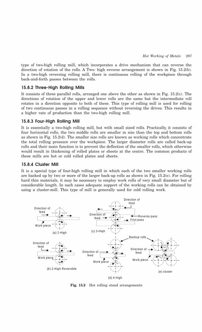
Hot Working of Metals 287
type of two-high rolling mill, which incorporates a drive mechanism that can reverse thedirection of rotation of the rolls. A Two- high reverse arrangement is shown in Fig. 15.2(b).In a two-high reversing rolling mill, there is continuous rolling of the workpiece throughback-and-forth passes between the rolls.
15.8.2 Three-High Rolling MillsIt consists of three parallel rolls, arranged one above the other as shown in Fig. 15.2(c). Thedirections of rotation of the upper and lower rolls are the same but the intermediate rollrotates in a direction opposite to both of these. This type of rolling mill is used for rollingof two continuous passes in a rolling sequence without reversing the drives. This results ina higher rate of production than the two-high rolling mill.
15.8.3 Four-High Rolling MillIt is essentially a two-high rolling mill, but with small sized rolls. Practically, it consists offour horizontal rolls, the two middle rolls are smaller in size than the top and bottom rollsas shown in Fig. 15.2(d). The smaller size rolls are known as working rolls which concentratethe total rolling pressure over the workpiece. The larger diameter rolls are called back-uprolls and their main function is to prevent the deflection of the smaller rolls, which otherwisewould result in thickening of rolled plates or sheets at the centre. The common products ofthese mills are hot or cold rolled plates and sheets.
15.8.4 Cluster MillIt is a special type of four-high rolling mill in which each of the two smaller working rollsare backed up by two or more of the larger back-up rolls as shown in Fig. 15.2(e). For rollinghard thin materials, it may be necessary to employ work rolls of very small diameter but ofconsiderable length. In such cases adequate support of the working rolls can be obtained byusing a cluster-mill. This type of mill is generally used for cold rolling work.
Direction of feed
W ork p iece
(a) 2 -H igh
D irection of feed
D irection of feed
(c) 3 -H igh
Reverse passFirs t pass
Backup rolls
(b ) 2 -H igh Reversible
D irection of feed
W ork p iece
D irection of feed
D irection of feed
W ork p ieceW ork p iece
(d) 4 -H igh
(e ) c luster
Fig. 15.2 Hot rolling stand arrangements

288 Introduction to Basic Manufacturing Processes and Workshop Technology
15.8.5 Continuous Rolling MillIt consists of a number of non reversing two-high rolling mills arranged one after the other,so that the material can be passed through all of them in sequence. It is suitable for massproduction work only, because for smaller quantities quick changes of set-up will be requiredand they will consume lot of time and labor.
15.8.6 Applications of RollingIn the rail mill (Fig. 15.2(f)), the heavier structural sections and rails are made. Rolling millsproduce girders, channels, angle irons and tee-irons. Plate mill rolls slabs into plates. Thematerials commonly hot rolled are aluminium, copper magnesium, their alloys and manygrades of steel.
Fig. 15.2(f) Hot rolling stand arrangements
15.9 Hot Piercing or Seamless tubingHot piercing is also known as seamless tubingor roll piercing process. The process setup isshown in Fig. 15.3. It is used for making thin-walled round objects. Seamless tube forming ispopular and economical process in comparisonto machining because it saves material wastedin boring of parts.
Round solidb illet
P ierc ingro lls
M andrel
Fig. 15.3 Hot piercing or seamless tubing

Hot Working of Metals 289
Hot pircing includes rotary piercing to obtain formed tube by piercing a pointed mandrelthrough a billet in a specially designed rolling mill. The rotary piercing can be performedeither on a two-high rolling mill or on a three-high rolling mill. In the former, the two rollsare set at an angle to each other. The billet under the rolls is deformed and a cavity formationis initiated at the centre due to tensile stressing. The carefully profiled shape of the mandrelassists and controls the formation of cavity. In a three-high rolling mill, the three shaped rollsare located at 1200 and their axes are inclined at a feed angle to permit forward and rotarymotion of the billet. The squeezing and bulging of the billet open up a seam in its center passmakes a rather thick-walled tube which is again passed over plug and through grooved rollsin a two-high roll mill where the thickness is decreased and the length is increased. Whileit is still up to a temperature, it is passed on to a reeling machine which has two rolls similarto the piercing rolls, but with flat surfaces. If more accuracy and better finish are desired,the run through sizing dies or rolls. After cooling, the tubes are used in a pickling bath ofdilute sulphuric acid to remove the scale.
15.10 HOT EXTRUSION
It is the process of enclosing the heated billet or slug of metal in a closed cavity and thenpushing it to flow from only one die opening so that the metal will take the shape of theopening. The pressure is applied either hydraulically or mechanically. Extrusion process isidentical to the squeezing of tooth paste out of the tooth paste tube. Tubes, rods, hose, casing,brass cartridge, moulding-trims, structural shapes, aircraft parts, gear profiles, cable sheathingetc. are some typical products of extrusion. Using extrusion process, it is possible to makecomponents, which have a constant cross-section over any length as can be had by the rollingprocess. The intricacy in parts that can be obtained by extrusion is more than that of rolling,because the die required being very simple and easier to make. Also extrusion is a single passprocess unlike rolling. The amount of reduction that is possible in extrusion is large. Generallybrittle materials can also be easily extruded. It is possible to produce sharp corners and re-entrant angles. It is also possible to get shapes with internal cavities in extrusion by the useof spider dies, which are explained later.
The extrusion setup consists of a cylinder container into which the heated billet or slug ofmetal is loaded. On one end of the container, the die plate with the necessary opening is fixed. Fromthe other end, a plunger or ram compresses the metal billet against the container walls and thedie plate, thus forcing it to flow through the die opening, acquiring the shape of the opening. Theextruded metal is then carried by the metal handling system as it comes out of the die.
The extrusion ratio is defined as the ratio of cross- sectional area of the billet to thatof the extruded section. The typical values of the extrusion ratio are 20 to 50. Horizontalhydraulic presses of capacities between 250 to 5500 tonnes are generally used for conventionalextrusion. The pressure requirement for extrusion is varying from material to material. Theextrusion pressure for a given material depends on the extrusion temperature, the reductionin area and the extrusion speed.
15.10.1 Methods of Hot ExtrusionHot extrusion process is classified as
1. Direct or forward hot extrusion
2. Indirect or backward hot extrusion
3. Tube extrusion

290 Introduction to Basic Manufacturing Processes and Workshop Technology
Different methods of extrusion are shown in Fig. 15.4. Each method is described asunder.
15.10.1.1 Direct or Forward Hot ExtrusionFig. 15.4 (a) shows the direct extrusion operational setup. In this method, the heated
metal billet is placed in to the die chamber and the pressure is applied through ram. Themetal is extruded through die opening in the forward direction, i.e. the same as that of theram. In forward extrusion, the problem of friction is prevalent because of the relative motionbetween the heated metal billet and the cylinder walls. To reduce such friction, lubricants areto be commonly used. At lower temperatures, a mixture of oil and graphite is generally used.The problem of lubrication gets compounded at the higher operating temperatures. Moltenglass is generally used for extruding steels.
15.10.1.2 Indirect or Backward Hot ExtrusionFig. 15.4 (b) shows the indirect extrusion operational setup. In indirect extrusion, the
billet remains stationary while the die moves into the billet by the hollow ram (or punch),through which the backward extrusion takes place. Since, there is no friction force betweenthe billet and the container wall, therefore, less force is required by this method. Howeverthis process is not widely used because of the difficulty occurred in providing support for theextruded part.
15.10.1.3 Tube ExtrusionFig. 15.4 (c and d) shows the tube extrusion operational setup. This process is an
extension of direct extrusion process where additional mandrel is needed to restrict flow ofmetal for production of seamless tubes. Aluminium based toothpaste and medicated tubes areproduced using this process.
Ram
Cylinder D ie
Extruded product
So lid s tock
Extrusiond irection
(a )
So lid s tock D ie Ram
Extrusiond irection
Extruded productCylinder
Ram direction
(b )
(c) (d )
Cylinder
D ie
Cylinder
D ie
Fig. 15.4 Method of hot extrusion
15.11 HOT DRAWING
Drawing is pulling of metal through a die or a set of dies for achieving a reduction in adiameter. The material to be drawn is reduced in diameter. Fig. 15.5 is another method usedin hot drawing or shaping of materials where the heated blank is placed over the die opening

Hot Working of Metals 291
the punch forces the blank through the die opening to form a cup or shell. The multiple diesare also used to accomplish the stages in drawing process. Kitchen utensils and componentsof food processing industries are manufactured by this process.
Punch
Heatedp la te
D ie
Heatedcup
Drawn part
D rawn part
D ie
Fig. 15.5 Hot drawing
15.12 HOT SPINNING
Hot spinning is a process in which pressure and plastic flow is used to shape material.Spinning may be either hot or cold and is generally carried over a spinning lathe. In bothcases, the metal is forced to flow over a rotating shape by pressure of a blunt tool as shownin Fig. 15.6. The amount of pressure of the blunt tool against the disc controls the generatedheat, which helps in forming processes.
Sheet be ing spinned
Compression pad
Tail s tock cen tre
P inSp inning tool
Too l post
Form B lock
M andrel
Head stock
Fig. 15.6 Hot spinning
QUESTIONS
1. What do you understand by mechanical working of metals?
2. Define re-crystalline temperature.
3. Differentiate between hot and cold working.
4. Define hot working of metals. What are its advantages and disadvantages?
5. Describe with sketches the three methods of hot working.
6. Explain briefly the various methods of hot extrusion with neat sketches.

292 Introduction to Basic Manufacturing Processes and Workshop Technology
7. What is hot extrusion? In how many ways it can be performed?
8. Describe briefly with neat sketches all the process of extrusions.
9. Discuss their relative merits and demerits of different kind of extrusion.
10. How welded pipes and tubes are manufactured?
11. Describe the process of hot extrusion of tubes.
12. What is roll piercing? And for what purpose is it used?
13. Write Short notes on:
(a) Hot spinning (b) Hot Extrusion
(c) Hot forging (d) Hot drawing.
14. Explain hot rolling and various type of rolling mills used in hot rolling.
15. Write short notes on the following:
(i) Hot piercing
(ii) Hot forging
(iii) Forging
16. How and why are directional properties obtained in a forged component? Discuss theiradvantages, dis-advantages and applications.
17. What are the advantages of hot extrusion over rolling and forging?
18. With the aid of a sketch, briefly describe the process of spinning. Why is it called a flowturning process?

293
COLD WORKING
16.1 INTRODUCTION
Cold working of a metal is carried out below its recrystallisation temperature. Althoughnormal room temperatures are ordinarily used for cold working of various types of steel,temperatures up to the recrystallisation range are sometimes used. In cold working, recoveryprocesses are not effective.
16.2 PURPOSE OF COLD WORKING
The common purpose of cold working is given as under1. Cold working is employed to obtain better surface finish on parts.2. It is commonly applied to obtain increased mechanical properties.3. It is widely applied as a forming process of making steel products using pressing and
spinning.4. It is used to obtain thinner material.
16.3 PRECAUTIONS FALLOWED IN COLD WORKING
Cold working leads to crack formation and propagation if performed in excess and it shouldtherefore be avoided. Residual stresses developed due to inhomogeneous deformation causewarping or distortion when the part is released from the tooling and during subsequentmachining. Magnitude and distribution of residual stresses should therefore be controlled.Orange-peel and stretcher strains are material related types of roughness defects found onsurfaces not touched by tooling. The former can be avoided by using fine grained sheets andlatter is minimized by temper rolling or stretching the strip to prevent localized yielding.
16.4 CHARACTERISTICS OF COLD WORKING
The main characteristics of cold working are given as under.
1. Cold working involves plastic deformation of a metal, which results in strainhardening.
2. It usually involves working at ordinary (room) temperatures, but, for high meltingpoint metals, e.g., tungsten, the cold working may be carried out at a red heat.
16CHAPTER

294 Introduction to Basic Manufacturing Processes and Workshop Technology
3. The stress required for deformation increases rapidly with the amount of deformation.
4. The amount of deformation, which can be performed without introducing othertreatment, is limited.
5. Cold rolling process generally distorts grain structure.
6. Good surface finish is obtained in cold rolling.
7. The upper temperature limit for cold working is the maximum temperature atwhich strain hardening is retained. Since cold working takes place below therecrystallisation temperature, it produces strain hardening.
8. Excessive cold working gives rise to the formation and propagation of cracks in themetal.
9. The loss of ductility during cold working has a useful side effect in machining.
10. With less ductility, the chips break more readily and facilitate the cutting operation.
11. Heating is sometimes required.
12. Directional properties can be easily imparted.
13. Spring back is a common phenomenon present in cold-working processes.
14. For relatively ductile metals, cold working is often more economical than hot working.
There is some increase and some decrease in properties of the cold worked part, whichare given as under.
Cold working process increases:• Ultimate tensile strength• Yield strength• Hardness• Fatigue strength• Residual stresses
Cold working processes decreases:• Percentage elongation• Reduction of area• Impact strength• Resistance to corrosion• Ductility
16.4 LIMITATIONS OF COLD WORKING
1. The cold worked process possesses less ductility.
2. Imparted directional properties may be detrimental
3. Strain hardening occurs.
4. Metal surfaces must be clean and scale free before cold working.
5. Hot worked metal has to be pickled in acid to remove scale, etc.
6. Higher forces are required for deformation than those in hot working.
7. More powerful and heavier equipments are required for cold working.
Cold Working 295
16.5 ADVANTAGES OF COLD WORKING
1. In cold working processes, smooth surface finish can be easily produced.
2. Accurate dimensions of parts can be maintained.
3. Strength and hardness of the metal are increased but ductility decreased.
4. Since the working is done in cold state, no oxide would form on the surface andconsequently good surface finish is obtained.
5. Cold working increases the strength and hardness of the material due to the strainhardening which would be beneficial in some situations.
6. There is no possibility of decarburization of the surface
7. Better dimensional accuracy is achieved.
8. It is far easier to handle cold parts and it is also economical for smaller sizes.
16.6 DISADVANTAGES OF COLD WORKING
1. Some materials, which are brittle, cannot be cold worked easily.
2. Since the material has higher yield strength at lower temperatures, the amount ofdeformation that can be given to is limited by the capability of the presses orhammers used.
3. A distortion of the grain structure is created.
4. Since the material gets strain hardened, the maximum amount of deformation thatcan be given is limited. Any further deformation can be given after annealing.
5. Internal stresses are set up which remain in the metal unless they are removed byproper heat-treatment.
16.7 COMPARISON OF HOT WORKING WITH COLD WORKING
The comparison of hot working with cold working is given in Table 16.1.
Table 16.1 Comparison of Hot Working with Cold Working
S. No. Hot Working Cold Working
1. Hot working is carried out above the Cold working is carried out belowrecrystallisation temperature and below the recrystallisation temperature. As such,the melting point. Hence the deformation there is no appreciable recovery.of metal and recovery take placesimultaneously.
2. No internal or residual stresses are In this process internal or residual stressesset-up in the metal in hot working. are set-up in the metal.
3. It helps in irradiating irregularities in It results in loss of uniformity ofmetal composition breaking up the non metal composition and thus affects themetallic impurities in to tiny fragments metal properties.and dispersing them through out themetal and thus facilitate uniformity ofcomposition in the metal
296 Introduction to Basic Manufacturing Processes and Workshop Technology
4. Close tolerance can not be maintained Better tolerance can be easily maintained.5. Surface finish of this process is Surface finish of this process is better.
comparatively not good
6. It results in improvements of properties It results in improvements of propertieslike impact strength and elongation like impact strength and elongation.
7. Due to re-crystallisation and recovery Since this is done below re-crystallisationno or very negligible hardening of metal temperature the metal gets work hardened.takes place.
8. Due to higher deformation temperatures, The stress required to cause deformationthe stress required for deformation is is much higher.much less.
9. Hot working refines metal grains resulting Most of the cold working processesin improved mechanical properties. lead to distortion of grains.
10. If cracks and blow boles are present in In cold working the existing cracksthe metal, they are finished through hot propagate and new cracks mayworking. develop
11. If properly performed, it does not affect It improves UTS, hardness, yield strengthUTS, hardness, corrosion resistance, but reduces the corrosion resistanceyield strength and fatigue strength of of strength of the metal.the metal.
16.8 COLD WORKING PROCESSES
Commonly employed cold working processes are:
1. Rolling
2. Extrusion
3. Wire drawing
4. Forging
5. Sheet metal operations
(a) Shearing etc.
(i) Piercing (ii) Blanking
(iii) Cutting (iv) Parting
(v) Punching (vi) Notching
(vii) Slitting (viii) Nibbling(ix) Lancing (x) Trimming
(b) Bending(c) Drawing(d) Pressing and deep drawing(e) Squeezing
(i) Embossing(ii) Coining
6. Cold spinning7. Shot peening

Cold Working 297
Cold working processes are also similar to hot working processes. Some of the importantcolds working processes are described as under.
16.9 COLD-ROLLING
Cold rolling process setup is similar to hot rolling. Bars of all shapes such as rods, sheets andstrips are commonly finished by rolling. Foil is made of the softer metals in this way. Cold-rolling metals impart smooth bright surface finish and in good physical and mechanicalproperties to cold rolled parts. If the objective is only to give a clean, smooth finishing metal,only a superficial amount of rolling will be needed. On the other hand, where it is desirablethat the tensile strength and stiffness be increased substantially, the section thickness issignificantly reduced, and then higher roll pressures and deeper kneading are necessary. Coldrolling also improves machinability in the cold rolled part by conferring the property ofbrittleness, a condition, which is conducive to smooth tool, finishes with broken chips. Thepreliminary step to the cold-rolling operation, the sheets of pre hot-rolled steel are immersedin an acid solution to remove the washed in water and then dried. The cleaned steel is passedthrough set of rolls of cold rolling process thereby producing a slight reduction in each therequired thickness is obtained.
The arrangement of rolls in a rolling mill, also called rolling stand, varies depending onthe application. The various possible configurations of rolls are similar to hot rolling. Thenames of the rolling stand arrangements are generally given by the number of rolls employed.These stands are more expensive compared to the non-reversible type because of the reversibledrive needed. Internal stresses are set up in cold rolled parts which remain in the metalunless they are removed by proper heat-treatment. This process needs more power foraccomplishing the operation in comparison to hot rolling.
16.10 COLD EXTRUSION
Principle of cold extrusion is similar to that of hot extrusion, which has been discussed underhot extrusion in section 15.10. The dissimilarity is that material in hot working processesshould possess the essential ductility with out the application of heat. Impact extrusion is alsoa cold extrusion process. It is used for making small components from ductile materials.Impact extrusion process is shown in Fig. 16.1. Impact extrusion of material is accomplishedwhere the work blank is placed in position over the die opening the punch forces the blankthrough the die opening causing material to flow plastically around the punch. The outsidediameter of the tube is same as diameter of the die, and the thickness is controlled by theclearance between punch and die. Collapsible medicare tubes and toothpastes etc. are producedusing this impact extrusion.
Punch
Extrudedtube
BlankD ie
Fig. 16.1 Impact extrusion
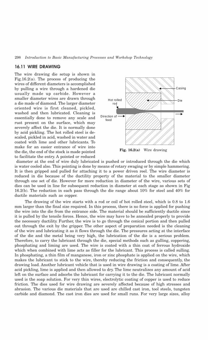
298 Introduction to Basic Manufacturing Processes and Workshop Technology
16.11 WIRE DRAWING
The wire drawing die setup is shown inFig.16.2(a). The process of producing thewires of different diameters is accomplishedby pulling a wire through a hardened dieusually made up carbide. However asmaller diameter wires are drawn througha die made of diamond. The larger diameteroriented wire is first cleaned, pickled,washed and then lubricated. Cleaning isessentially done to remove any scale andrust present on the surface, which mayseverely affect the die. It is normally doneby acid pickling. The hot rolled steel is de-scaled, pickled in acid, washed in water andcoated with lime and other lubricants. Tomake for an easier entrance of wire intothe die, the end of the stock is made pointedto facilitate the entry. A pointed or reduced diameter at the end of wire duly lubricated is pushed or introduced through the die whichis water cooled also. This pointing is done by means of rotary swaging or by simple hammering.It is then gripped and pulled for attaching it to a power driven reel. The wire diameter isreduced in die because of the ductility property of the material to the smaller diameterthrough one set of die. However for more reduction in diameter of the wire, various sets ofdies can be used in line for subsequent reduction in diameter at each stage as shown in Fig16.2(b). The reduction in each pass through the die range about 10% for steel and 40% forductile materials such as copper.
The drawing of the wire starts with a rod or coil of hot rolled steel, which is 0.8 to 1.6mm larger than the final size required. In this process, there is no force is applied for pushingthe wire into the die from the entrance side. The material should be sufficiently ductile sinceit is pulled by the tensile forces. Hence, the wire may have to be annealed properly to providethe necessary ductility. Further, the wire is to go through the conical portion and then pulledout through the exit by the gripper. The other aspect of preparation needed is the cleaningof the wire and lubricating it as it flows through the die. The pressures acting at the interfaceof the die and the metal being very high, the lubrication of the die is a serious problem.Therefore, to carry the lubricant through the die, special methods such as gulling, coppering,phosphating and liming are used. The wire is coated with a thin coat of ferrous hydroxidewhich when combined with lime acts as filler for the lubricant. This process is called sulling.In phosphating, a thin film of manganese, iron or zinc phosphate is applied on the wire, whichmakes the lubricant to stick to the wire, thereby reducing the friction and consequently, thedrawing load. Another lubricant vehicle that is used in wire drawing is a coating of lime. Afteracid pickling, lime is applied and then allowed to dry. The lime neutralizes any amount of acidleft on the surface and adsorbs the lubricant for carrying it to the die. The lubricant normallyused is the soap solution. For very thin wires, electrolytic coating of copper is used to reducefriction. The dies used for wire drawing are severely affected because of high stresses andabrasion. The various die materials that are used are chilled cast iron, tool steels, tungstencarbide and diamond. The cast iron dies are used for small runs. For very large sizes, alloy
Hot ro lledrod
D irection of feed
D ie
Casing
Fig. 16.2(a) Wire drawing

Cold Working 299
steels are used in making the dies. The tungsten carbide dies are used most commonly formedium size wires and large productions. The tungsten carbide dies are referred because oftheir long life that is 2 to 3 times that of alloy steel dies. For very fine wires, diamond diesare used. Wire drawing improves the mechanical properties because of the cold working. Thematerial loses its ductility during the wire drawing process and when it is to be repeatedlydrawn to bring it to the final size, intermediate annealing is required to restore the ductility.
O rig ina l w ire co il
D raw p la tes(D ies)
Capstan d rum
Rece iv ing co il
Fig. 16.2(b) Wire drawing
16.12 SHEET METAL PROCESSES
Sheet metal work processing is highly common in manufacturing sheet metal parts usingfrom sheet stock. The various sheet metal operations are performed on press machine ofrequired capacity using press tools or dies. The dies may be single operation die or multi-operation dies. A simple piercing, blanking and shearing die is shown in Fig. 16.3. Howeverthe basic sheet metal operations are described in the following lines.
16.12.1 General Sheet Metal Operations
ShearingIt takes place when punch and die are used. The quality of the cut surface is greatly
influenced by the clearance between the two shearing edges. However, the basic shearingoperations are described in the following lines.
CuttingIt means severing a piece from a strip with a cut along a single line.
Punch ho lder
Punch
StripperBack gage
D ie b lock
D ie shoe
Sheet m eta ls tock
Fig. 16.3 Typical simple press tool

300 Introduction to Basic Manufacturing Processes and Workshop Technology
PartingIt signifies that scrap is removed between the two pieces to part them.
BlankingIt means cutting a whole piece from sheet metal just enough scrap is left all around the
opening to assure that the punch has metal to cut along its entire edge. The piece detachedfrom the strip is known as blank and is led for further operations. The remaining metal stripis scrap. Blanking is nearly almost the first operation and may be the only one necessary orit may be followed successively by many others. Blanking is often combined with other operationsin one tool, all the work being performed at one stroke of the press. A blanking die must haveclearance, otherwise the blank would not fall freely, and it might remain struck in the die block.
PunchingIt is the operation of producing circular holes on a sheet metal by a punch and die. The
material punched out is removed as waste. Piercing, on the other hand, is the process ofproducing holes of any desired shape.
NotchingIt is a process of removing metal to the desired shape from the side or edge of a sheet
or strip.
SlittingWhen shearing is conducted between rotary blades, the process is referred to as slitting.
It cuts the sheet metal lengthwise.
NibblingIt is an operation of cutting any shape from sheet metal without special tools. It is done
on a nibbling machine.
TrimmingIt is the operation of cutting away excess metal in a flange or flash from a piece.
LancingIt makes a cut part way across a strip.
FormingIt is a metal working process in which the shape of the punch and the die is directly
reproduced in the metal with little or no metal flow.
16.12.2 BendingIt is employed for bending into desired shapes various stock materials like sheets, rods, wires,bars, pipes, tubes and various structural shapes. Formed dies are used for bending the articlesand the operation is usually performed in many stages. For bending in all sheet material arestressed beyond the elastic limit in tension on the outside and in compression on the insideof the bend. There is only one line, the natural line which retains its original length. Theneutral axis lies at a distance of 30 to 50% of thickness of the sheet from the inside of thebend. Stretching of the sheet metal on the outside makes the stock thinner. Bending issometimes called as forming which involves angle bending, roll bending, and roll forming and
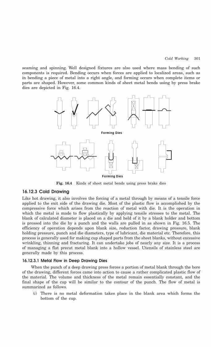
Cold Working 301
seaming and spinning. Well designed fixtures are also used where mass bending of suchcomponents is required. Bending occurs when forces are applied to localized areas, such asin bending a piece of metal into a right angle, and forming occurs when complete items orparts are shaped. However, some common kinds of sheet metal bends using by press brakedies are depicted in Fig. 16.4.
Forming Dies
Forming Dies
Fig. 16.4 Kinds of sheet metal bends using press brake dies
16.12.3 Cold DrawingLike hot drawing, it also involves the forcing of a metal through by means of a tensile forceapplied to the exit side of the drawing die. Most of the plastic flow is accomplished by thecompressive force which arises from the reaction of metal with die. It is the operation inwhich the metal is made to flow plastically by applying tensile stresses to the metal. Theblank of calculated diameter is placed on a die and held of it by a blank holder and bottomis pressed into the die by a punch and the walls are pulled in as shown in Fig. 16.5. Theefficiency of operation depends upon blank size, reduction factor, drawing pressure, blankholding pressure, punch and die diameters, type of lubricant, die material etc. Therefore, thisprocess is generally used for making cup shaped parts from the sheet blanks, without excessivewrinkling, thinning and fracturing. It can undertake jobs of nearly any size. It is a processof managing a flat precut metal blank into a hollow vessel. Utensils of stainless steel aregenerally made by this process.
16.12.3.1 Metal Flow in Deep Drawing DiesWhen the punch of a deep drawing press forces a portion of metal blank through the bore
of the drawing, different forces came into action to cause a rather complicated plastic flow ofthe material. The volume and thickness of the metal remain essentially constant, and thefinal shape of the cup will be similar to the contour of the punch. The flow of metal issummarized as follows.
(i) There is no metal deformation takes place in the blank area which forms thebottom of the cup.
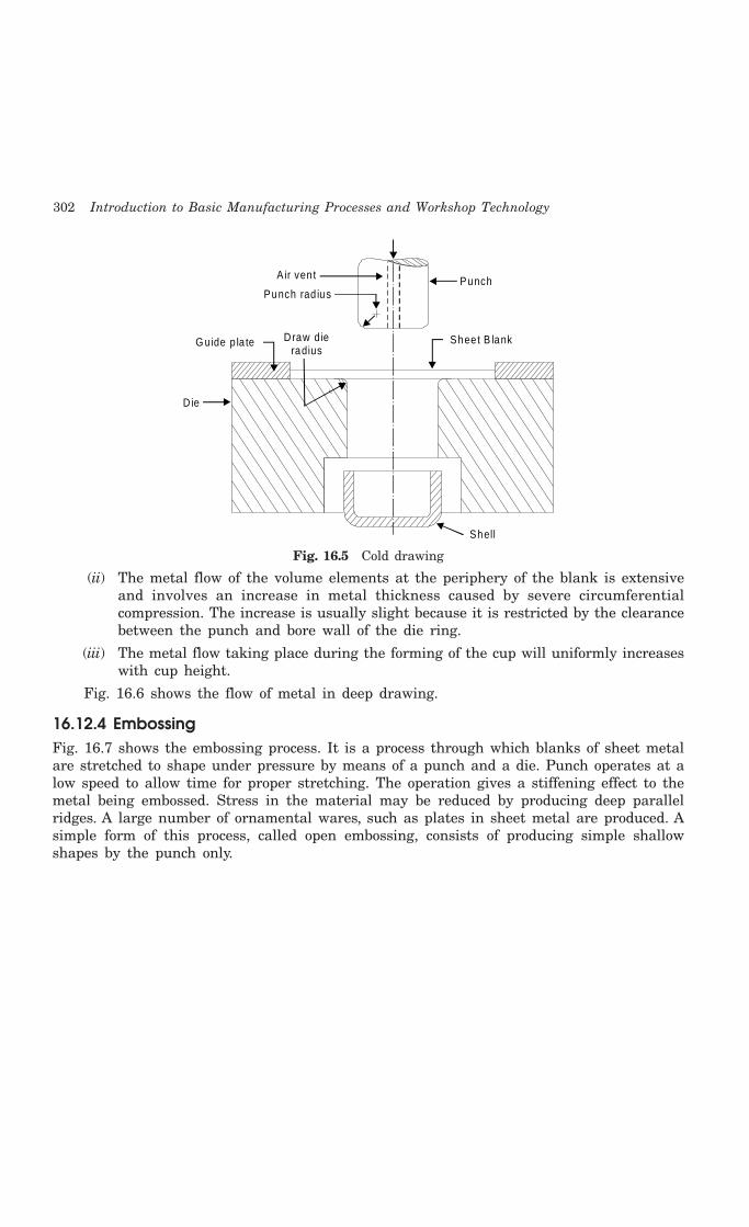
302 Introduction to Basic Manufacturing Processes and Workshop Technology
Air ven t
Punch rad ius
G uide p la te
D ie
Punch
Sheet B lank
Shell
D raw d ieradius
Fig. 16.5 Cold drawing
(ii) The metal flow of the volume elements at the periphery of the blank is extensiveand involves an increase in metal thickness caused by severe circumferentialcompression. The increase is usually slight because it is restricted by the clearancebetween the punch and bore wall of the die ring.
(iii) The metal flow taking place during the forming of the cup will uniformly increaseswith cup height.
Fig. 16.6 shows the flow of metal in deep drawing.
16.12.4 EmbossingFig. 16.7 shows the embossing process. It is a process through which blanks of sheet metalare stretched to shape under pressure by means of a punch and a die. Punch operates at alow speed to allow time for proper stretching. The operation gives a stiffening effect to themetal being embossed. Stress in the material may be reduced by producing deep parallelridges. A large number of ornamental wares, such as plates in sheet metal are produced. Asimple form of this process, called open embossing, consists of producing simple shallowshapes by the punch only.

Cold Working 303
Each section m ustcom press m ore than the prev ious section
Sheet b lank
1 2 3 4
(a )Pressure
Blank ho lder
Draw d ie
M etal in th is a rea w ill straigh ten upon fu rther penetra tion
Punch
(b)
(c)
Sheet B lank
Pressure
Fig. 16.6 Metal flow in deep drawing
Pressure Form ing Punch
D ie
Co inedpart
Fig. 16.7 Embossing

304 Introduction to Basic Manufacturing Processes and Workshop Technology
16.12.5 CoiningFig 16.8 shows the coining process used in cold workingoperations. It is basically a cold working operation,which is performed in dies where the metal blank isconfined and its lateral flow is restricted. It is mainlyused for production of important articles such as medals,coins, stickers and other similar articles, which possessshallow configurations on their surfaces. The operationinvolves placing a metal slug in the die and applyingheavy pressure by the punch. The metal flows plasticallyand is squeezed to the shape between punch and thedie. The process, on account of the very high pressuresrequired, can be employed only for soft metals withhigh plasticity.
16.12.6 Roll FormingIt consists of feeding a continuous metal sheet or strip through a series of rolls whereby itis formed into desired shapes. The roll formed sections can be used in as formed conditionwith their both edges separate from each other. Alternatively, they can be welded to form aclosed section such as tubing and pipes. A number of rolls employed in the series depend uponthe shape to be formed. The forming arrangement carries guide rolls and straighteningdevices also.
16.13 SHOT PEENING
It is a process of increasing the hardness and fatigue strength on parts surfaces. The processcomprises of throwing a blast of metal shot on to the surface of a component requiring shotpeening. It is used to set up a superficial state of surface compression stress, causing theinterior of the member to assume an opposite tensile stress. Blast may be thrown either byair pressure or with help of a wheel revolving at high speed. This high velocity blast of metalshot provides a sort of compression over the components surface and increases hardness andstrength of the surface and also its fatigue resistance.
16.14 QUESTIONS1. Differentiate between hot working and cold working.
2. Define cold working of metals. What are its advantages and disadvantages?
3. What are the specific advantages, limitations and applications of cold working?
4. Explain the various cold drawing processes.
5. Using neat sketches explain briefly the process of wire-drawing.
6. Describe the process of cold spinning stating its advantages and specific uses.
7. Explain briefly the stretch forming operation.
8. Write short notes on the cold rolling and cold extrusion.
9. What is cold forging and swaging?
10. What for cold heading is used?
11. Explain the process of rotary swaging with the help of a neat sketch.
Form ing Punch
Sectionembossed
D ie
Fig. 16.8 Coining
Cold Working 305
12. What is impact extrusion? Explain this process and state its specific applications.
13. Describe the following cold working processes:
(i) Embossing
(ii) Coining
(iii) Roll forming
(iv) Roll bending
(v) Shot peening
14. Explain the following cold working processes:
(i) Cold rolling
(ii) Stretch forming
(iii) Cold hobbing
(iv) Cold bending.
15. Write short notes on the following:
(i) Cold forging
(ii) Hobbing
(iii) Embossing
(iv) Staking
(v) Ironing
(vi) Shot peening.
16. Discuss the methods used for the production of pipes and tubes.
17. Using neat sketch describe briefly the method of extruding a hollow round collapsible tubewith help of drawing process.

306 Introduction to Basic Manufacturing Processes and Workshop Technology
306
WELDING
17.1 INTRODUCTION
Welding is a process for joining two similar or dissimilar metals by fusion. It joins differentmetals/alloys, with or without the application of pressure and with or without the use of fillermetal. The fusion of metal takes place by means of heat. The heat may be generated eitherfrom combustion of gases, electric arc, electric resistance or by chemical reaction. Duringsome type of welding processes, pressure may also be employed, but this is not an essentialrequirement for all welding processes. Welding provides a permanent joint but it normallyaffects the metallurgy of the components. It is therefore usually accompanied by post weldheat treatment for most of the critical components. The welding is widely used as a fabricationand repairing process in industries. Some of the typical applications of welding include thefabrication of ships, pressure vessels, automobile bodies, off-shore platform, bridges, weldedpipes, sealing of nuclear fuel and explosives, etc.
Most of the metals and alloys can be welded by one type of welding process or the other.However, some are easier to weld than others. To compare this ease in welding term‘weldability’ is often used. The weldability may be defined as property of a metal whichindicates the ease with which it can be welded with other similar or dissimilar metals.Weldability of a material depends upon various factors like the metallurgical changes thatoccur due to welding, changes in hardness in and around the weld, gas evolution and absorption,extent of oxidation, and the effect on cracking tendency of the joint. Plain low carbon steel(C-0.12%) has the best weldability amongst metals. Generally it is seen that the materialswith high castability usually have low weldability.
17.2 TERMINOLOGICAL ELEMENTS OF WELDING PROCESS
The terminological elements of welding process used with common welding joints such asbase metal, fusion zone, weld face, root face, root opening toe and root are depicted in Fig.17.1
17.2.1 Edge preparationsFor welding the edges of joining surfaces of metals are prepared first. Different edge preparationsmay be used for welding butt joints, which are given in Fig 17.2.
17CHAPTER

Welding 307
W eld faceFusion zone
Base m etal
Root face
Root open ing
(a) Bu tt weld
Toe
W eld face
Toe
Root
(b ) Fillet weld
Fusion zone
Fig. 17.1 Terminological elements of welding process
Straigh t
S ing le - V
Doub le - V
S ing le bevel
Doub le bevel
S ing le - U
Doub le - U
S ing le - J
Doub le - J
Fig. 17.2 Butt welding joints edge preparations
17.2.2 Welding jointsSome common welding joints are shown in Fig. 17.3. Welding joints are of generally of twomajor kinds namely lap joint and butt joint. The main types are described as under.
17.2.2.1 Lap weld joint
Single-Lap JointThis joint, made by overlapping the edges of the plate, is not recommended for most
work. The single lap has very little resistance to bending. It can be used satisfactorily forjoining two cylinders that fit inside one another.
Double-Lap JointThis is stronger than the single-lap joint but has the disadvantage that it requires twice
as much welding.
Tee Fillet WeldThis type of joint, although widely used, should not be employed if an alternative design
is possible.
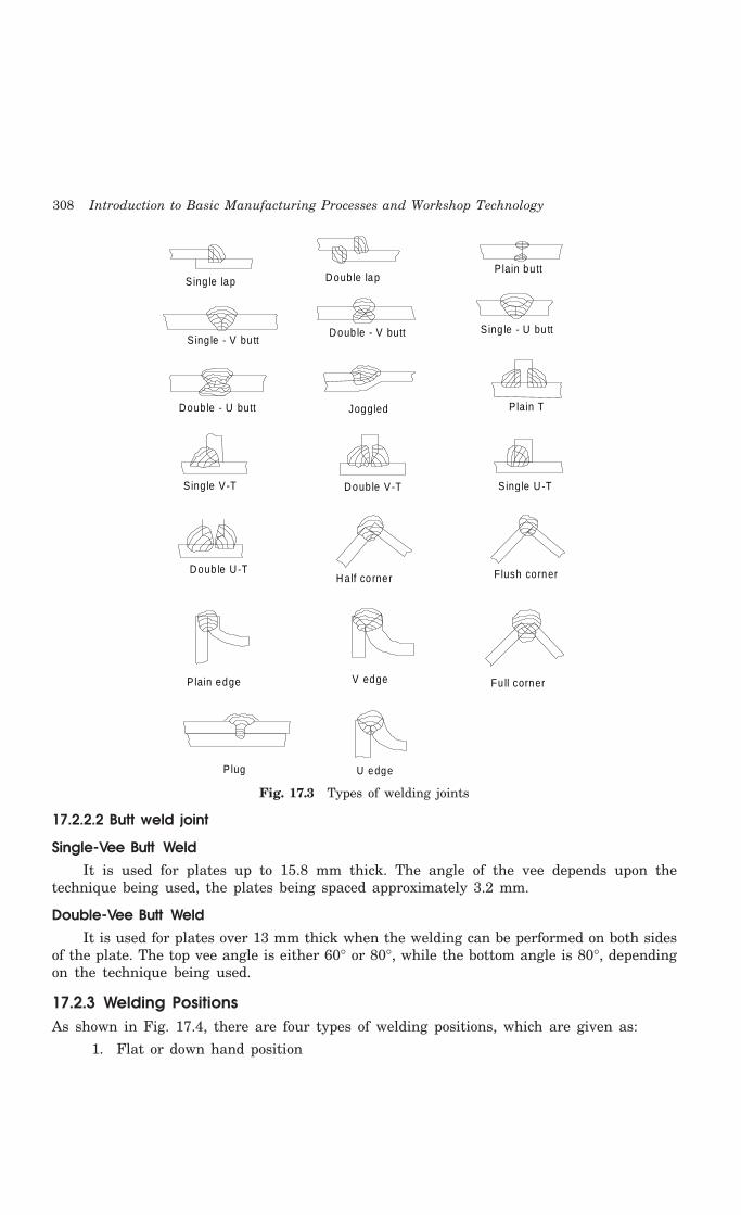
308 Introduction to Basic Manufacturing Processes and Workshop Technology
Plain bu tt
S ing le - V bu tt Doub le - V butt S ing le - U bu tt
Doub le - U butt
S ing le lap Doub le lap
Joggled P lain T
Sing le V-T Doub le V-T S ing le U -T
Doub le U -T Flush cornerHa lf co rner
Fu ll corner P lain edge V edge
U edgePlug
Fig. 17.3 Types of welding joints
17.2.2.2 Butt weld joint
Single-Vee Butt WeldIt is used for plates up to 15.8 mm thick. The angle of the vee depends upon the
technique being used, the plates being spaced approximately 3.2 mm.
Double-Vee Butt WeldIt is used for plates over 13 mm thick when the welding can be performed on both sides
of the plate. The top vee angle is either 60° or 80°, while the bottom angle is 80°, dependingon the technique being used.
17.2.3 Welding PositionsAs shown in Fig. 17.4, there are four types of welding positions, which are given as:
1. Flat or down hand position
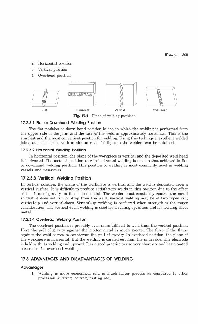
Welding 309
2. Horizontal position
3. Vertical position
4. Overhead position
Flat Vertica l Horizon ta l O ver head
Fig. 17.4 Kinds of welding positions
17.2.3.1 Flat or Downhand Welding PositionThe flat position or down hand position is one in which the welding is performed from
the upper side of the joint and the face of the weld is approximately horizontal. This is thesimplest and the most convenient position for welding. Using this technique, excellent weldedjoints at a fast speed with minimum risk of fatigue to the welders can be obtained.
17.2.3.2 Horizontal Welding PositionIn horizontal position, the plane of the workpiece is vertical and the deposited weld head
is horizontal. The metal deposition rate in horizontal welding is next to that achieved in flator downhand welding position. This position of welding is most commonly used in weldingvessels and reservoirs.
17.2.3.3 Veritical Welding PositionIn vertical position, the plane of the workpiece is vertical and the weld is deposited upon avertical surface. It is difficult to produce satisfactory welds in this position due to the effectof the force of gravity on the molten metal. The welder must constantly control the metalso that it does not run or drop from the weld. Vertical welding may be of two types viz.,vertical-up and vertical-down. Vertical-up welding is preferred when strength is the majorconsideration. The vertical-down welding is used for a sealing operation and for welding sheetmetal.
17.2.3.4 Overhead Welding PositionThe overhead position is probably even more difficult to weld than the vertical position.
Here the pull of gravity against the molten metal is much greater. The force of the flameagainst the weld serves to counteract the pull of gravity. In overhead position, the plane ofthe workpiece is horizontal. But the welding is carried out from the underside. The electrodeis held with its welding end upward. It is a good practice to use very short arc and basic coatedelectrodes for overhead welding.
17.3 ADVANTAGES AND DISADVANTAGES OF WELDING
Advantages1. Welding is more economical and is much faster process as compared to other
processes (riveting, bolting, casting etc.)

310 Introduction to Basic Manufacturing Processes and Workshop Technology
2. Welding, if properly controlled results permanent joints having strength equal orsometimes more than base metal.
3. Large number of metals and alloys both similar and dissimilar can be joined bywelding.
4. General welding equipment is not very costly.
5. Portable welding equipments can be easily made available.
6. Welding permits considerable freedom in design.
7. Welding can join welding jobs through spots, as continuous pressure tight seams,end-to-end and in a number of other configurations.
8. Welding can also be mechanized.
Disadvantages1. It results in residual stresses and distortion of the workpieces.
2. Welded joint needs stress relieving and heat treatment.
3. Welding gives out harmful radiations (light), fumes and spatter.
4. Jigs, and fixtures may also be needed to hold and position the parts to be welded
5. Edges preparation of the welding jobs are required before welding
6. Skilled welder is required for production of good welding
7. Heat during welding produces metallurgical changes as the structure of the weldedjoint is not same as that of the parent metal.
17.4 CLASSIFICATION OF WELDING AND ALLIED PROCESSES
There are different welding, brazing and soldering methods are being used in industries today.There are various ways of classifying the welding and allied processes. For example, they maybe classified on the basis of source of heat, i.e., blacksmith fire, flame, arc, etc. and the typeof interaction i.e., liquid / liquid (fusion welding) or solid/solid (solid state welding). Weldingprocesses may also be classified in two categories namely plastic (forge) and fusion. However,the general classification of welding and allied processes is given as under
(A) Welding Processes
1. Oxy-Fuel Gas Welding Processes1 Air-acetylene welding
2 Oxy-acetylene welding
3 Oxy-hydrogen welding
4 Pressure gas welding
2. Arc Welding Processes1. Carbon Arc Welding
2. Shielded Metal Arc Welding
3. Submerged Arc Welding
4. Gas Tungsten Arc Welding
Welding 311
5. Gas Metal Arc Welding
6. Plasma Arc Welding
7. Atomic Hydrogen Welding
8. Electro-slag Welding
9. Stud Arc Welding
10. Electro-gas Welding
3. Resistance Welding1. Spot Welding
2. Seam Welding
3. Projection Welding
4. Resistance Butt Welding
5. Flash Butt Welding
6. Percussion Welding
7. High Frequency Resistance Welding
8. High Frequency Induction Welding
4. Solid-State Welding Processes1. Forge Welding
2. Cold Pressure Welding
3. Friction Welding
4. Explosive Welding
5. Diffusion Welding
6. Cold Pressure Welding
7. Thermo-compression Welding
5. Thermit Welding Processes1. Thermit Welding
2. Pressure Thermit Welding
6. Radiant Energy Welding Processes1. Laser Welding
2. Electron Beam Welding
(B) Allied Processes
1. Metal Joining or Metal Depositing Processes1. Soldering
2. Brazing
3. Braze Welding
4. Adhesive Bonding
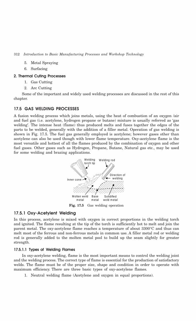
312 Introduction to Basic Manufacturing Processes and Workshop Technology
5. Metal Spraying
6. Surfacing
2. Thermal Cuting Processes1. Gas Cutting
2. Arc Cutting
Some of the important and widely used welding processes are discussed in the rest of thischapter.
17.5 GAS WELDING PROCESSES
A fusion welding process which joins metals, using the heat of combustion of an oxygen /airand fuel gas (i.e. acetylene, hydrogen propane or butane) mixture is usually referred as ‘gaswelding’. The intense heat (flame) thus produced melts and fuses together the edges of theparts to be welded, generally with the addition of a filler metal. Operation of gas welding isshown in Fig. 17.5. The fuel gas generally employed is acetylene; however gases other thanacetylene can also be used though with lower flame temperature. Oxy-acetylene flame is themost versatile and hottest of all the flames produced by the combination of oxygen and otherfuel gases. Other gases such as Hydrogen, Propane, Butane, Natural gas etc., may be usedfor some welding and brazing applications.
W elding to rch tip
D irection of we ld ing
M olten we ld m etal
Base m etal
So lidified we ld m eta l
W elding rod
Inner cone
Fig. 17.5 Gas welding operation
17.5.1 Oxy-Acetylent WeldingIn this process, acetylene is mixed with oxygen in correct proportions in the welding torchand ignited. The flame resulting at the tip of the torch is sufficiently hot to melt and join theparent metal. The oxy-acetylene flame reaches a temperature of about 3300°C and thus canmelt most of the ferrous and non-ferrous metals in common use. A filler metal rod or weldingrod is generally added to the molten metal pool to build up the seam slightly for greaterstrength.
17.5.1.1 Types of Welding FlamesIn oxy-acetylene welding, flame is the most important means to control the welding joint
and the welding process. The correct type of flame is essential for the production of satisfactorywelds. The flame must be of the proper size, shape and condition in order to operate withmaximum efficiency. There are three basic types of oxy-acetylene flames.
1. Neutral welding flame (Acetylene and oxygen in equal proportions).
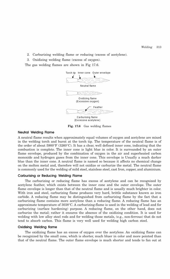
Welding 313
2. Carburizing welding flame or reducing (excess of acetylene).
3. Oxidizing welding flame (excess of oxygen).
The gas welding flames are shown in Fig 17.6.
Torch tip Inner cone O uter enve lope
Neutra l flam e
Feather
Carburis ing flam e(Excessive acety lene )
O xid iz ing flam e(Excessive oxygen)
Fig. 17.6 Gas welding flames
Neutral Welding FlameA neutral flame results when approximately equal volumes of oxygen and acetylene are mixedin the welding torch and burnt at the torch tip. The temperature of the neutral flame is ofthe order of about 5900°F (3260°C). It has a clear, well defined inner cone, indicating that thecombustion is complete. The inner cone is light blue in color. It is surrounded by an outerflame envelope, produced by the combination of oxygen in the air and superheated carbonmonoxide and hydrogen gases from the inner cone. This envelope is Usually a much darkerblue than the inner cone. A neutral flame is named so because it affects no chemical changeon the molten metal and, therefore will not oxidize or carburize the metal. The neutral flameis commonly used for the welding of mild steel, stainless steel, cast Iron, copper, and aluminium.
Carburising or Reducing Welding FlameThe carburizing or reducing flame has excess of acetylene and can be recognized by
acetylene feather, which exists between the inner cone and the outer envelope. The outerflame envelope is longer than that of the neutral flame and is usually much brighter in color.With iron and steel, carburizing flame produces very hard, brittle substance known as ironcarbide. A reducing flame may be distinguished from carburizing flame by the fact that acarburizing flame contains more acetylene than a reducing flame. A reducing flame has anapproximate temperature of 3038°C. A carburizing-flame is used in the welding of lead and forcarburizing (surface hardening) purpose. A reducing flame, on the other hand, does notcarburize the metal; rather it ensures the absence of the oxidizing condition. It is used forwelding with low alloy steel rods and for welding those metals, (e.g., non-ferrous) that do nottend to absorb carbon. This flame is very well used for welding high carbon steel.
Oxidising Welding flameThe oxidizing flame has an excess of oxygen over the acetylene. An oxidizing flame can
be recognized by the small cone, which is shorter, much bluer in color and more pointed thanthat of the neutral flame. The outer flame envelope is much shorter and tends to fan out at

314 Introduction to Basic Manufacturing Processes and Workshop Technology
the end. Such a flame makes a loud roaring sound. It is the hottest flame (temperature ashigh as 6300°F) produced by any oxy-fuel gas source. But the excess oxygen especially at hightemperatures tends to combine with many metals to form hard, brittle, low strength oxides.Moreover, an excess of oxygen causes the weld bead and the surrounding area to have ascummy or dirty appearance. For these reasons, an oxidizing flame is of limited use inwelding. It is not used in the welding of steel. A slightly oxidizing flame is helpful whenwelding (i) Copper-base metals (ii) Zinc-base metals and (iii) A few types of ferrous metals suchas manganese steel and cast iron. The oxidizing atmosphere in these cases, create a base-metal oxide that protects the base metal.
17.5.1.2 Gas Welding EquipmentsAn arrangement of oxy acetylene welding set up is shown in Fig.17.7. The basic tools and
equipments used for oxy-acetylene welding are following:
19
20
21
22
10
8
12 13 1716
1815
1411
654
23 7
9
Oxy
gen
Ace
t yle
ne
1 . Ace tylene hose2. Ad justing screw3. Ace tylene regulator4 . Regu la to r ou tlet pressure gauge5. Cylinder pressure gauge6. Valve w rench7. Ace tylene cy linder valve8 . Cylinder cap
9. Fusib le plugs10. O xygen hose11. O xygen regu la to r12. Regulator ou tle t p ressure gauge13. Cylinder p ressure gauge14. Cylinder cap15. O xygen cy linder valve16. O xygen cy linder valve
17. Hand wheel 18. Bursting d isc19. Acety lene va lve20. O xygen va lve21. Weld ing to rch22. Torch tip23. Flam e
23
Fig. 17.7 Oxy acetylene welding set up
Acetylene and oxygen gas is stored in compressed gas cylinders. These gas cylindersdiffer widely in capacity, design and colour code. However, in most of the countries, thestandard size of these cylinders is 6 to 7 m3 and is painted black for oxygen and maroon foracetylene. An acetylene cylinder is filled with some absorptive material, which is saturatedwith a chemical solvent acetone. Acetone has the ability to absorb a large volume of acetyleneand release it as the pressure falls. If large quantities of acetylene gas are being consumed,it is much cheaper to generate the gas at the place of use with the help of acetylene gasgenerators. Acetylene gas is generated by carbide-to-water method.
Oxygen gas cylinders are usually equipped with about 40 litres of oxygen at a pressureof about 154 Kgf/cm2 at 21°C. To provide against dangerously excessive pressure, such as

Welding 315
could occur if the cylinders were exposed to fire, every valve has a safety device to releasethe oxygen before there is any danger of rupturing the cylinders. Fragile discs and fusibleplugs are usually provided in the cylinders valves in case it is subjected to danger.
Gas pressure regulatorsGas pressure regulators are employed for regulating the supply of acetylene and oxygen
gas from cylinders. A pressure regulator is connected between the cylinder and hose leadingto welding torch. The cylinder and hose connections have left-handed threads on the acetyleneregulator while these are right handed on the oxygen regulator. A pressure regulator is fittedwith two pressure gauges, one for indication of the gas pressure in the cylinder and the otherfor indication of the reduced pressure at which the gas is going out.
Welding torchFig 17.8 shows the construction of the welding torch. It is a tool for mixing oxygen and
acetylene in correct proportion and burning the mixture at the end of a tip. Gas flow to thetorch is controlled with the help of two needle valves in the handle of the torch. There aretwo basic types of gas welding torches:
(1) Positive pressure (also known as medium or equal pressure), and
(2) Low pressure or injector type
The positive pressure type welding torch is the more common of the two types of oxy-acetylene torches.
Flam eM ix ing cham ber O xygen
Acetylene
Need le valve con tro l C H hose
2 2
O hose
2
Fig. 17.8 Welding torch
Torch tipsIt is the portion of the welding apparatus through which the gases pass just prior to their
ignition and burning. A great variety of interchangeable welding tips differing in size, shapeand construction are available commercially. The tip sizes are identified by the diameter ofthe opening. The diameter of the tip opening used for welding depends upon the type of metalto be welded.
Hose pipesThe hose pipes are used for the supply of gases from the pressure regulators. The most
common method of hose pipe fitting both oxygen and acetylene gas is the reinforced rubberhose pipe. Green is the standard color for oxygen hose, red for acetylene, and black hose forother industrially available welding gases.
316 Introduction to Basic Manufacturing Processes and Workshop Technology
GogglesThese are fitted with colored lenses and are used to protect the eyes from harmful heat
and ultraviolet and infrared rays.
GlovesThese are required to protect the hands from any injury due to the heat of welding
process.
Spark-lighterIt is used for frequent igniting the welding torch.
Filler rodsGas welding can be done with or without using filler rod. When welding with the filler
rod, it should be held at approximately 900 to the welding tip. Filler rods have the same ornearly the same chemical composition as the base metal. Metallurgical properties of the welddeposit can be controlled by the optimum choice of filler rod. Most of the filler rods for gaswelding also contain deoxidizers to control the oxygen content of weld pool.
FluxesFluxes are used in gas welding to remove the oxide film and to maintain a clean surface.
These are usually employed for gas welding of aluminium, stainless steel, cast iron, brass andsilicon bronze. They are available in the market in the form of dry powder, paste, or thicksolutions.
17.5.2 Safety Recommendations for Gas WeldingWelding and cutting of metals involve the application of intense heat to the objects beingwelded or cut. This intense heat in welding is obtained from the use of inflammable gases,(e.g. acetylene, hydrogen, etc.) or electricity. The intense welding heat and the sourcesemployed to produce it can be potentially hazardous. Therefore, to protect persons frominjury and to protect building and equipment against fire, etc., a set of recommendationsconcerning safety and health measures for the welders and those concerned with the safetyof the equipments etc., have been published by BIS and many other similar but Internationalorganizations. By keeping in mind these recommendations or precautions, the risks associatedwith welding can be largely reduced. Therefore, it is suggested that the beginner in the fieldof gas welding must go through and become familiar with these general safetyrecommendations, which are given below.
1. Never hang a torch with its hose on regulators or cylinder valves.
2. During working, if the welding tip becomes overheated it may be cooled by plungingthe torch into water; close the acetylene valve but leave a little oxygen flowing.
3. Always use the correct pressure regulators for a gas. Acetylene pressure regulatorshould never be used with any other gas.
4. Do not move the cylinder by holding the pressure regulator and also handle pressureregulators carefully.
5. Use pressure regulator only at pressures for which it is intended.
6. Open cylinder valves slowly to avoid straining the mechanism of pressure regulator.
7. Never use oil, grease or lubricant of any kind on regulator connections.

Welding 317
8. For repairs, calibrations and adjustments purposes, the pressure regulators shouldbe sent to the supplier.
9. Do cracking before connecting pressure regulator to the gas cylinder.
10. Inspect union nuts and connections on regulators before use to detect faulty seatswhich may cause leakage of gas when the regulators are attached to the cylindervalves.
11. Hose connections shall be well fittings and clamped properly otherwise securelyfastened to these connections in such a manner as to withstand without leakage apressure twice as great as the maximum delivery pressure of the pressure regulatorsprovided on the system.
12. Protect the hose from flying sparks, hot slag, hot workpiece and open flame. If dirtgoes into hose, blow through (with oxygen, not acetylene) before coupling to torchor regulator.
13. Store hose on a reel (an automobile wheel) when not in use.
14. Never allow the hose to come into contact with oil or grease; these deteriorate therubber and constitute a hazard with oxygen.
15. Use the correct color hose for oxygen (green/black) and acetylene (red) and neveruse oxygen hose for acetylene or vice versa.
16. Always protect hose from being trampled on or run over. Avoid tangle and kinks.Never leave the hose so that it can be tripped over.
Hazards of fumes, gases and dusts can be minimized by (i) improving general ventilationof the place where welding is carried out (ii) using local exhaust units, and (iii) wearingindividual respiratory protective equipment.
17.6 ARC WELDING PROCESSES
The process, in which an electric arc between an electrode and a workpiece or between twoelectrodes is utilized to weld base metals, is called an arc welding process. The basic principleof arc welding is shown in Fig 17.9(a). However the basic elements involved in arc weldingprocess are shown in Fig. 17.9(b). Most of these processes use some shielding gas while othersemploy coatings or fluxes to prevent the weld pool from the surrounding atmosphere. Thevarious arc welding processes are:
1. Carbon Arc Welding
2. Shielded Metal Arc Welding
3. Flux Cored Arc Welding
4. Gas Tungsten Arc Welding
5. Gas Metal Arc Welding
6. Plasma Arc Welding
7. Atomic Hydrogen Welding
8. Electroslag Welding
9. Stud Arc Welding
10. Electrogas Welding

318 Introduction to Basic Manufacturing Processes and Workshop Technology
Electrode
W eldbead
W ork
E lectrode Ho lder
Cable
AC
W eldingm ach ineEarth ing
Fig. 17.9(a) Principle of arc welding
12
53
6
11
6
8
10
9
1716
13 14 15
12
(1) Sw itch box.(2 ) Secondary term ina ls .(3 ) W elding m ach ine.(4 ) Curren t reading sca le .(5 ) Curren t regulating hand wheel.(6 ) Lea ther apron .
(7 ) Asbestos hand gloves.(8 ) Pro tective glasses strap .(9 ) E lectrode holder.(10) Hand sh ie ld .(11) Channe l for cable pro tection.(12) Weld ing cable.
(13) Chipp ing hamm er.(14) W ire b rush .(15) Earth clam p.(16) Weld ing tab le (m etallic).(17) Job.
Fig. 17.9(b) Arc welding process setup
17.6.1 Arc Welding EquipmentArc welding equipment, setup and related tools and accessories are shown in Fig. 17.9.However some common tools of arc welding are shown separately through Fig. 17.10-17.17.Few of the important components of arc welding setup are described as under.
1. Arc welding power sourceBoth direct current (DC) and alternating current (AC) are used for electric arc welding,
each having its particular applications. DC welding supply is usually obtained from generatorsdriven by electric motor or if no electricity is available by internal combustion engines. ForAC welding supply, transformers are predominantly used for almost all arc welding where

Welding 319
mains electricity supply is available. They have to step down the usual supply voltage (200-400 volts) to the normal open circuit welding voltage (50-90 volts). The following factorsinfluence the selection of a power source:
1. Type of electrodes to be used and metals to be welded
2. Available power source (AC or DC)
3. Required output
4. Duty cycle
5. Efficiency
6. Initial costs and running costs
7. Available floor space
8. Versatility of equipment
Fig. 17.10 Electrode holder Fig. 17.11 Earth clamp
Poin t
Hand le
Ch isel
Fig. 17.12 Hand screen Fig. 17.13 Chipping and hammer
Hand le
Fig. 17.14 Wire brush Fig. 17.15 C-clamp

320 Introduction to Basic Manufacturing Processes and Workshop Technology
Scriber
Fig. 17.16 V-block Fig. 17.17 Scriber
2. Welding cablesWelding cables are required for conduction of current from the power source through
the electrode holder, the arc, the workpiece and back to the welding power source. These areinsulated copper or aluminium cables.
3. Electrode holderElectrode holder is used for holding the electrode mannually and conducting current to
it. These are usually matched to the size of the lead, which in turn matched to the amperageoutput of the arc welder. Electrode holders are available in sizes that range from 150 to 500Amps.
4. Welding ElectrodesAn electrode is a piece of wire or a rod of a metal or alloy, with or without coatings. An
arc is set up between electrode and workpiece. Welding electrodes are classified into followingtypes-
(1) Consumable Electrodes
(a) Bare Electrodes
(b) Coated Electrodes
(2) Non-consumable Electrodes
(a) Carbon or Graphite Electrodes
(b) Tungsten Electrodes
Consumable electrode is made of different metals and their alloys. The end of thiselectrode starts melting when arc is struck between the electrode and workpiece. Thusconsumable electrode itself acts as a filler metal. Bare electrodes consist of a metal or alloywire without any flux coating on them. Coated electrodes have flux coating which startsmelting as soon as an electric arc is struck. This coating on melting performs many functionslike prevention of joint from atmospheric contamination, arc stabilizers etc.
Non-consumable electrodes are made up of high melting point materials like carbon,pure tungsten or alloy tungsten etc. These electrodes do not melt away during welding. Butpractically, the electrode length goes on decreasing with the passage of time, because ofoxidation and vaporization of the electrode material during welding. The materials of non-consumable electrodes are usually copper coated carbon or graphite, pure tungsten, thoriatedor zirconiated tungsten.
5. Hand ScreenHand screen (Fig. 17.12) used for protection of eyes and supervision of weld bead.

Welding 321
6. Chipping hammerChipping Hammer (Fig. 17.13) is used to remove the slag by striking.
7. Wire brushWire brush (Fi. 17.14) is used to clean the surface to be weld.
8. Protective clothingOperator wears the protective clothing such as apron to keep away the exposure of direct
heat to the body.
17.6.2 Carbon Arc WeldingIn this process, a pure graphite or baked carbon rod is used as a non-consumable electrodeto create an electric arc between it and the workpiece. The electric arc produces heat andweld can be made with or without the addition of filler material. Carbon arc welding may beclassified as-
(1) Single electrode arc welding, and
(2) Twin carbon electrode arc welding
In single electrode arc welding, an electric arc is struck between a carbon electrode andthe workpiece. Welding may be carried out in air or in an inert atmosphere. Direct currentstraight polarity (DCSP) is preferred to restrict electrode disintegration and the amount ofcarbon going into the weld metal. This process is mainly used for providing heat source forbrazing, braze welding, soldering and heat treating as well as for repairing iron and steelcastings. It is also used for welding of galvanized steel and copper.
In twin carbon arc welding the arc struck between two carbon electrodes produces heatand welds the joint. The arc produced between these two electrodes heats the metal to themelting temperature and welds the joint after solidification. The power source used is AC(Alternating Current) to keep the electrodes at the same temperature. Twin-electrode carbonarc welding can be used for welding in any position. This process is mainly used for joiningcopper alloys to each other or to ferrous metal. It can also be used for welding aluminium,nickel, zinc and lead alloys.
17.6.3 Shielded Metal Arc Welding (SMAW) or Manual Metal Arc Welding (MMAW)
Shielded metal arc welding (SMAW) is a commonly used arc welding process manually carriedby welder. It is an arc welding process in which heat for welding is produced through anelectric arc set up between a flux coated electrode and the workpiece. The flux coating ofelectrode decomposes due to arc heat and serves many functions, like weld metal protection,arc stability etc. Inner core of the electrode supply the filler material for making a weld. Thebasic setup of MMAW is depicted in Fig. 17.9 (a), (b) and the configuration of weld zone isshown in Fig. 17.18. If the parent metal is thick it may be necessary to make two or threepasses for completing the weld. A typical multi pass bead in this case is shown in Fig. 17.19.
Advantages1. Shielded Metal Arc Welding (SMAW) can be carried out in any position with highest
weld quality.
2. MMAW is the simplest of all the arc welding processes.

322 Introduction to Basic Manufacturing Processes and Workshop Technology
3. This welding process finds innumerable applications, because of the availability ofa wide variety of electrodes.
4. Big range of metals and their alloys can be welded easily.
5. The process can be very well employed for hard facing and metal resistance etc.
6. Joints (e.g., between nozzles and shell in a pressure vessel) which because of theirposition are difficult to be welded by automatic welding machines can be easilyaccomplished by flux shielded metal arc welding.
7. The MMAW welding equipment is portable and the cost is fairly low.
Electrode
Coating Core W ire
D irection o f travel
D rops o f m etal being deposited
Stag Bead
ArcArc crater
G aseous sh ie ld
So lidified weld m eta l M olten m etal
Penetra tion Base m etal
Fig. 17.18 Arc welding operation
4321Root
Fig. 17.19 A typical multi pass bead
Limitations1. Due to flux coated electrodes, the chances of slag entrapment and other related
defects are more as compared to MIG and TIG welding.2. Duo to fumes and particles of slag, the arc and metal transfer is not very clear and
thus welding control in this process is a bit difficult as compared to MIG welding.3. Due to limited length of each electrode and brittle flux coating on it, mechanization
is difficult.4. In welding long joints (e.g., in pressure vessels), as one electrode finishes, the weld
is to be progressed with the next electrode. Unless properly cared, a defect (like slaginclusion or insufficient penetration) may occur at the place where welding is restartedwith the new electrode
5. The process uses stick electrodes and thus it is slower as compared to MIG welding.
Applications1. Today, almost all the commonly employed metals and their alloys can be welded by
this process.
Welding 323
2. Shielded metal arc welding is used both as a fabrication process and for maintenanceand repair jobs.
3. The process finds applications in
(a) Building and Bridge construction
(b) Automotive and aircraft industry, etc.
(c) Air receiver, tank, boiler and pressure vessel fabrication
(d) Ship building
(e) Pipes and
(f) Penstock joining
17.6.3.1 Functions of Electrode Coating IngredientsThe covering coating on the core wire consists of many materials which perform a
number of functions as listed below:
1. Welding electrodes are used to join various similar and dissimilar metals as plaincarbon steels, cast iron, copper, aluminium, magnesium and their alloys, stainlesssteels and other alloy steels.
2. Slag forming ingredients, like silicates of magnesium, aluminium, sodium, potassium,iron oxide, china clay, mica etc., produce a slag which because of its light weightforms a layer on the molten metal and protects the same from atmosphericcontamination.
3. Arc stabilizing constituents like calcium carbonate, potassium silicate, titanates,magnesium silicates, etc.; add to arc stability and ease of striking the same.
4. Gas shielding ingredients, like cellulose, wood, wood flour, starch, calcium carbonateetc. form a protective gas shield around the electrode end, arc and weld pool
5. Deoxidizing elements like ferro-manganese, and ferro-silicon, refine the moltenmetal.
6. It limits spatter, produces a quiet arc and easily removable slag.7. Alloying elements like ferro alloys of manganese, molybdenum etc., may be added
to impart suitable properties and strength to the weld metal and to make good theloss of some of the elements, which vaporize while welding.
8. Iron powder in the coating improves arc behavior, bead appearance helps increasemetal deposition rate and arc travel speed.
9. The covering improves penetration and surface finish.10. Core wire melts faster than the covering, thus forming a sleeve of the coating which
constricts and produces an arc with high concentrated heat.11. Coating saves the welder from the radiations otherwise emitted from a bare electrode
while the current flows through it during welding.12. Proper coating ingredients produce weld metals resistant to hot and cold cracking.
Suitable coating will improve metal deposition rates.
17.6.4 Submerged Arc WeldingSchematic submerged arc welding process is shown in Fig. 17.20. In this welding process, aconsumable bare electrode is used in combination with a flux feeder tube. The arc, end of the
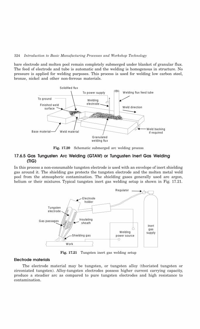
324 Introduction to Basic Manufacturing Processes and Workshop Technology
bare electrode and molten pool remain completely submerged under blanket of granular flux.The feed of electrode and tube is automatic and the welding is homogenous in structure. Nopressure is applied for welding purposes. This process is used for welding low carbon steel,bronze, nickel and other non-ferrous materials.
Solidified flux
To g round
Finished we ld surface
Base m ater ial W eld materia l
G ranu la ted we ld ing flux
W elding flux feed tube
W eld direction
W eld backing if requ ired
To power supp ly
W elding e lectrode
Fig. 17.20 Schematic submerged arc welding process
17.6.5 Gas Tungusten Arc Welding (GTAW) or Tungusten Inert Gas Welding (TIG)
In this process a non-consumable tungsten electrode is used with an envelope of inert shieldinggas around it. The shielding gas protects the tungsten electrode and the molten metal weldpool from the atmospheric contamination. The shielding gases generally used are argon,helium or their mixtures. Typical tungsten inert gas welding setup is shown in Fig. 17.21.
Tungsten e lectrode
G as passages
Electrode holder
Insu la ting sheath
W elding power sourceSh ie ld ing gas
W ork
Regu la tor
Inert gas
supply
Fig. 17.21 Tungsten inert gas welding setup
Electrode materialsThe electrode material may be tungsten, or tungsten alloy (thoriated tungsten or
zirconiated tungsten). Alloy-tungsten electrodes possess higher current carrying capacity,produce a steadier arc as compared to pure tungsten electrodes and high resistance tocontamination.

Welding 325
Electric power sourceBoth AC and DC power source can be used for TIG welding. DC is preferred for welding
of copper, copper alloys, nickel and stainless steel whereas DC reverse polarity (DCRP) or ACis used for welding aluminium, magnesium or their alloys. DCRP removes oxide film onmagnesium and aluminium.
Inert gasesThe following inert gases are generally used in TIG welding:
1. Argon
2. Helium
3. Argon-helium mixtures
4. Argon-hydrogen mixtures
Tig NozzleThe nozzle or shield size (the diameter of the opening of the shroud around the electrode)
to be chosen depends on the shape of the groove to be welded as well as the required gasflow rate. The gas flow rate depends on the position of the weld as well as its size. Too higha gas consumption would give rise to turbulence of the weld metal pool and consequentlyporous welds. Because of the use of shielding gases, no fluxes are required to be used in inertgas shielded arc welding. However for thicker sections, it may be desirable to protect the rootside of the joint by providing a flux. The process is generally used for welding aluminium,magnesium and stainless steel.
17.6.6 Gas Metal ARC Welding (GMAW) or Metal Inert Gas Welding (MIG)Metal inert gas arc welding (MIG) or more appropriately called as gas metal arc welding(GMAW) utilizes a consumable electrode and hence, the term metal appears in the title.There are other gas shielded arc welding processes utilizing the consumable electrodes,such as flux cored arc welding (FCAW) all of which can be termed under MIG. Though gastungsten arc welding (GTAW) can be used to weld all types of metals, it is more suitablefor thin sheets. When thicker sheets are to be welded, the filler metal requirement makesGTAW difficult to use. In this situation, the GMAW comes handy. The typical setup forGMAW or MIG welding process is shown in Fig. 17.22. The consumable electrode is in theform of a wire reel which is fed at a constant rate, through the feed rollers. The weldingtorch is connected to the gas supply cylinder which provides the necessary inert gas. Theelectrode and the work-piece are connected to the welding power supply. The power suppliesare always of the constant voltage type only. The current from the welding machine ischanged by the rate of feeding of the electrode wire. Normally DC arc welding machinesare used for GMAW with electrode positive (DCRP). The DCRP increases the metal depositionrate and also provides for a stable arc and smooth electrode metal transfer. With DCSP, thearc becomes highly unstable and also results in a large spatter. But special electrodeshaving calcium and titanium oxide mixtures as coatings are found to be good for weldingsteel with DCSP. In the GMAW process, the filler metal is transferred from the electrodeto the joint. Depending on the current and voltage used for a given electrode, the metaltransfer is done in different ways.

326 Introduction to Basic Manufacturing Processes and Workshop Technology
C on tro l sys tem F eed c on tro l
G as ou t
G un con trol
W ire spoo l
G as in
R egu la to r
H and he ld gun
C ab le(pow er, gas , c oolent)
w o rk lead C on tacto r con tro l
110V supp ly
Pow er sou rce
S h ield ing gas
sou rcew ire feed
d rive m o tor
Fig. 17.22 Gas metal arc welding (GMAW) set up
17.6.7 Safety Recommendations for ARC WeldingThe beginner in the field of arc welding must go through and become familiar with thesegeneral safety recommendations which are given as under.
1. The body or the frame of the welding machine shall be efficiently earthed. Pipe linescontaining gases or inflammable liquids or conduits carrying electrical conductorsshall not be used for a ground return circuit All earth connections shall bemechanically strong and electrically adequate for the required current.
2. Welding arc in addition to being very is a source of infra-red and ultra-violet lightalso; consequently the operator must use either helmet or a hand-shield fitted witha special filter glass to protect eyes
3. Excess ultra-violet light can cause an effect similar to sunburn on the skin of the welder
4. The welder’s body and clothing are protected from radiation and burns caused bysparks and flying globules of molten metal with the help of the following:
5. Gloves protect the hands of a welder.
6. Leather or asbestos apron is very useful to protect welder’s clothes and his trunkand thighs while seated he is doing welding.
7. For overhead welding, some form of protection for the head is required
8. Leather skull cap or peaked cap will do the needful.
9. Leather jackets and 1ather leggings are also available as clothes for body protection.
10. Welding equipment shall be inspected periodically and maintained in safe workingorder at all times.
11. Arc welding machines should be of suitable quality.
12. All parts of welding set shall be suitably enclosed and protected to meet the usualservice conditions.

Welding 327
13. Welders and workers need to be protected from welding rays, f1ying sparks, metalglobules and metal spatter, hot slag particles, hot stubs, fumes and gases whenwelding in confined spaces, e.g., rail tank wagon, falling when welding at a heightfrom the ground.
14. In AC arc welding machines, in transformers, the secondary circuit shall be thoroughlyinsulated from the primary. Input terminal shall be completely enclosed and accessibleonly by means of tools.
15. The primary side of the transformer shall be provided with suitable wire terminalsinside the machine case.
16. Welding (secondary) terminals shall be so arranged that current carrying parts arenot exposed to accidental contact.
17. In a transformer, the welding circuit should be quite separate from power circuit,so that there is no risk of the welder suffering serious shock or burns throughpower voltage appearing across the electric holder.
18. At or near each welding machine, a disconnecting switch shall provide.
19. Control apparatus provided with the welding machine shall enclose except for theoperating wheels, levers, etc.
20. Transformer windings be suction or compressed-air cleaned periodically.
21. Before undertaking any maintenance work on welding machine disconnects themfrom the main supply.
22. As regards other arc welding equipments, electrode holders should be soundlyconnected to the welding lead
23. They should be of adequate rating for the maximum welding current to preventthem from heating up and be coming too hot to handle.
24. Electrode holder sha1l be provided with discs or shields to protect the hands of thewelder from heat of the arc. Installation of all metallic of current carrying parts,including the jaws which grip the electrodes, is recommended.
25. Hot electrode holders shall not be permitted to dip in water because the retainedmoisture may cause an electric shock.
26. Welding cables shall be of completely insulated, flexible type. They should be capableof handling the maximum current requirements of the work in progress, taking intoaccount the duty cycle under which the welder is working in case the cable insulationis damaged, do not operate the equipment.
27. The welding cable should be free from repair or splices up to a minimum distanceof three metres from the electrode holder.
28. Fully insulated cable connectors of capacity at least equivalent to that of the cableshall be used to connect two cables together.
29. Welding cables shall be kept dry and free from grease and oil to avoid prematurebreakdown of insulation.
30. Arc welding machines should be properly ground (earthed).
31. Construction of arc welding machines should be such that they can operatesatisfactorily even under conditions of saltish or moist air as in coastal areas, dust,

328 Introduction to Basic Manufacturing Processes and Workshop Technology
smoke, fumes and gases, excessive shock or vibrations, steam and corrosiveatmosphere, etc.
32. One should not work on the wiring of an arc welding machine unless qualified todo so.
33. Welding equipment used in the open and shall be protected from weather conditions.If it has been wetted it shall be thoroughly dried before being used.
34. Proper terminals should be used on the arc welding machines for the power linevoltage connection.
35. Neither terminal of the welding generator shall be bonded to the frame of thewelding machine.
36. Periodically clear out the accumulated dust from the welding machine with suctioncleaner as this will not blow dust into other parts of the machine.
37. Over greasing may foul the commutators of DC generator.
38. Check and, if necessary, clean commutators of DC generator periodically, using finesand paper.
39. Excessive sparking may result in a worn commutator of DC generator which maybe cured by skimming in a lathe.
40. Brushes should move freely and have adequate spring tension. This can be testedby lifting and releasing them. Brushes should snap be firmly against the commutatorof DC generator.
41. Greasing points need attention periodically.
42. Switch contacts should be cleaned periodically.
17.7 RESISTANCE WELDING
In resistance welding the metal parts to be joined are heated by their resistance to the flowof an electrical current. Usually this is the only source of heat, but a few of the weldingoperations combine resistance heating with arc heating, and possibly with combustion ofmetal in the arc. The process applies to practically all metals and most combinations of puremetals and those alloys, which have only a limited plastic range, are welded by heating theparts to fusion (melting). Some alloys, however, may welded without fusion; instead, the partsare heated to a plastic state at which the applied pressure causes their crystalline structuresto grow together. The welding of dissimilar metals may be accomplished by melting bothmetals frequently only the metal with the lower melting point is melted, and an alloy bondis formed at the surface of the unmelted metal.
In resistance welding processes no fluxes are employed, the filler metal is rarely usedand the joints are usually of the lap type. The amount of heat generated in the workpiecedepend on the following factors:
(1) Magnitude of the current,
(2) Resistance of the current conducting path, and
Mathematically, H = IVt
= I(IR)t
= I2Rt

Welding 329
Where H = heat generated in joules
I = current in Amp.
R = resistance in ohms
t = time of current flow in seconds.
17.7.1 Types of Resistance weldingThe major types of resistance welding are given as under:
(1) Spot Welding
(2) Seam Welding
(3) Projection Welding
(4) Resistance Butt Welding
(5) Flash Butt Welding
(6) Percussion Welding
(7) High Frequency Resistance Welding
(8) High Frequency Induction Welding
Some of the above important welding processes are discussed as under,
17.7.1.1 Spot WeldingIn this process overlapping sheets are joined by local fusion at one or more spots, by the
concentration of current flowing between two electrodes. This is the most widely used resistancewelding process. A typical resistance spot welding machine is shown in Fig. 17.23. It essentiallyconsists of two electrodes, out of which one is fixed. The other electrode is fixed to a rockerarm (to provide mechanical advantage) for transmitting the mechanical force from a pneumaticcylinder. This is the simplest type of arrangement. The other possibility is that of a pneumaticor hydraulic cylinder being directly connected to the electrode without any rocker arm. Forwelding large assemblies such as car bodies, portable spot welding machines are used. Herethe electrode holders and the pneumatic pressurizing system are present in the form of aportable assembly which is taken to the place, where the spot is to be made. The electriccurrent, compressed air and the cooling water needed for the electrodes is supplied throughcables and hoses from the main welding machine to the portable unit. In spot welding, asatisfactory weld is obtained when a proper current density is maintained. The currentdensity depends on the contact area between the electrode and the work-piece. With thecontinuous use, if the tip becomes upset and- the contact area increases, the current densitywill be lowered and consequently the weld is obtained over a large area. This would not be ableto melt the metal and hence there would be no proper fusion. A resistance welding scheduleis the sequence of events that normally take place in each of the welds. The events are:
1. The squeeze time is the time required for the electrodes to align and clamp the twowork-pieces together under them and provide the necessary electrical contact.
2. The weld time is the time of the current flow through the work-pieces till they areheated to the melting temperature.
3. The hold time is the time when the pressure is to be maintained on the moltenmetal without the electric current. During this time, the pieces are expected to beforged welded.

330 Introduction to Basic Manufacturing Processes and Workshop Technology
4. The off time is time during which, the pressure on the electrode is taken off so thatthe plates can be positioned for the next spot.
M ovable a rm
Fixed arm
Pressure
Fra
meJob
Regu la tor
Through contact to AC current supp ly
Transfo rm er
Water-coo led e lectrode
Fig. 17.23 Resistance spot welding machine setup
Before spot welding one must make sure that
(i) The job is clean, i.e., free from grease, dirt, paint, scale, oxide etc.
(ii) Electrode tip surface is clean, since it has to conduct the current into the work withas little loss as possible. Very fine emery cloth may be used for routine cleaning.
(iii) Water is running through the electrodes in order to
(a) Avoid them from getting overheated and thus damaged,
(b) Cool the weld.
(iv) Proper welding current has been set on the current selector switch.
(v) Proper time has been set on the weld-timer.
Spot welding electrodesSpot welding electrodes are made of materials which have
(1) Higher electrical and thermal resistivities, and
(2) Sufficient strength to withstand high pressure at elevated temperatures.
Copper base alloys such as copper beryllium and copper tungsten are commonly usedmaterials for spot welding electrodes. For achieving the desired current density, It is importantto have proper electrode shape for which three main types of spot welding electrodes are usedwhich are pointed, domed and flat electrodes.
Applications of Spot Welding(i) It has applications in automobile and aircraft industries
(ii) The attachment of braces, brackets, pads or clips to formed sheet-metal parts suchas cases, covers or trays is another application of spot welding.
(iii) Spot welding of two 12.5 mm thick steel plates has been done satisfactorily as areplacement for riveting.
(iv) Many assemblies of two or more sheet metal stampings that do not require gas tightor liquid tight joints can be more economically joined by spot welding than bymechanical methods.
(v) Containers and boxes frequently are spot welded.

Welding 331
17.7.1.2 Resistance Seam WeldingIt is a continuous type of spot welding wherein spot welds overlap each other to the desired
extent. In this process coalescence at the faying surfaces is produced by the heat obtained fromthe resistance to electric current (flow) through the work pieces held together under pressureby circular electrodes. The resulting weld is a series of overlapping resistance-spots welds madeprogressively along a joint by rotating the circular electrodes. The principle of seam welding isshown in Fig. 17.24(a) and resistance seam welding process set up is shown in Fig. 17.24(b). Theseam welding is similar to spot welding, except that circular rolling electrodes are used toproduce a continuous air-tight seam of overlapping welds. Overlapping continuous spot weldsseams are produced by the rotating electrodes and a regularly interrupted current.
Force
W heele lectrode
A.C .power
ContactorForce
M otor d riven
W heel electrode
W eld
W orkp iece
W eldingtransfo rm erand con tro ls
Foot sw itch
Fig. 17.24 (a) Principle of seam welding process Fig. 17.24 (b) Resistance seam welding process setup
Applications1. It is used for making leak proof joints in fuel tanks of automobiles.
2. Except for copper and high copper alloys, most other metals can be seam welded.
3. It is also used for making flange welds for use in watertight tanks.
17.7.1.3 Resistance Projection WeldingFig.17.25 shows the projection welding.
This process is a resistance welding process inwhich two or more than two spot welds aremade simultaneously by making raised portionsor projections on predetermined locations onone of the workpiece. These projections act tolocalize the heat of the welding circuit. Thepieces to be welded are held in position underpressure being maintained by electrodes. Theprojected contact spot for welding should beapproximately equal to the weld metalthickness. The welding of a nut on the auto-motive chasis is an example of projectionwelding.
Pressure
Pro jections
Fixede lectrode
W eldspots
AC
M oveab lee lectrode
Fig. 17.25 Resistance projection welding

332 Introduction to Basic Manufacturing Processes and Workshop Technology
17.7.1.4 Resistance Upset Butt and Flash Butt WeldingThis welding is also used for joining metal pieces end to end but it has largely replaced
the butt-welding method for weld articles small cross-sections. It can be used for thicksections also. Initially the current is switched on and then one end the moveable part to bewelded is brought gently closer to the fixed end of the other part to localize heat at the endsand thus raises the temperature of the ends quickly to the welding heat. On acquiring contactof fixed end and moveable end with each other, the moveable end is then pressed against oneanother by applying mechanical pressure. Thus the molten metal and slag to be squeezed outin the form of sparks enabling the pure metal to form the joint and disallowing the heat .tospread back. The principle of upset butt welding and flash butt welding are depicted in Fig.17.26 (a, b). In this resistance welding single phase A.C. machines are commonly employed.The merits and demerit of flash welding over simple butt-welding are follows:
W orkp iece Jaws W orkp iece
Joint
C lam ps
W orkp ieces
Flash
C lam ps
Fig. 17.26 (a) Resistance upset butt welding Fig. 17.26 (b) Resistance flash butt welding
Merits1. It is comparatively much faster than butt welding.
2. This method utilizes less current in comparison to butt welding as the small portionof the metal is only being heated for getting a good weld
3. Created joint by this welding is much stronger than the butt welding joint. Also thestrength of the weld produced is high even more than that of the base metal. Theend of the metal pieces to be welded in this welding need not be squared as it isthe basic requirement in butt-welding.
4. A high degree of accuracy can be easily achieved in terms of length alignment of weld.
Demerits1. The periodic maintenance of machine and replacement of insulation is needed as
flashing particles of molten metal are thrown out during welding which may enterinto the slide ways and insulation of the set up.
2. Welder has to take enough care against possible fire hazard due to flashing duringwelding.
3. Additional stock has to be provided for compensating loss of metal during f1ashingand upsetting. This increases to the cost of weld.
4. Cost of removal of flash weld metal by trimming, chipping, grinding, etc. will increaseto the welded product.

Welding 333
5. Surface of the jobs where they come in contact with the gripping surfaces, shouldbe clean otherwise they will restrict the flow of electric current.
6. The available power, opening between the jaws of the gripping clamps and upsettingpressure of the welding set limit the size and cross sectional area of the jobs to bewelded.
ApplicationsAll conducting forged metals can be easily be flash welded. A number of dissimilar metals
can also be welded by controlling the welding conditions carefully. Metals generally weldedmetal by the process involves lead, tin, antimony, zinc, bismuth and their alloys, low carbonsteels, stainless steel, alloy steels, tool steels, copper alloys, aluminium alloys, magnesiumalloys nickel alloys, molybdenum alloys, and titanium alloys. This process is used in automobileindustry, welding of solid and tubular structural assemblies, etc. in air-craft industry, weldingof band saw blades, welding of tool steel drills, reamers and taps etc. to mild steel or alloysteel shanks, welding of pipes and tubes.
17.7.2 Common Advantages of Resistance WeldingSome common advantages of resistance welding include:
(a) It is well suited for mass production.(b) It is economical in operation, since nothing is consumed except electrical power.(c) Skilled welders are not required.(d) Welds are quickly made.(e) It is possible to weld dissimilar metals.
Some disadvantages of resistance welding include:(a) High initial cost of the resistance welding equipment(b) Certain resistance welding processes are limited to lap joints.(c) A lap joint has an inherent service between the two metal pieces, which causes
stress concentrations in applications where fatigue is present. This service may alsocause trouble when corrosion is present
17.8 SOLID STATE WELDING PROCESSES
In these processes, the base materials to be joined are heated to a temperature below or justupto the solidus temperature and then continuous pressure is applied to form the weldedjoint. No filler metal is used in solid-state welding processes. The various solid-state weldingprocesses are-
(1) Forge Welding
(2) Cold Pressure Welding
(3) Friction Welding
(4) Explosive Welding
(5) Diffusion Welding
(6) Thermo-compression Welding
Some of the above important welding processes are discussed as under,
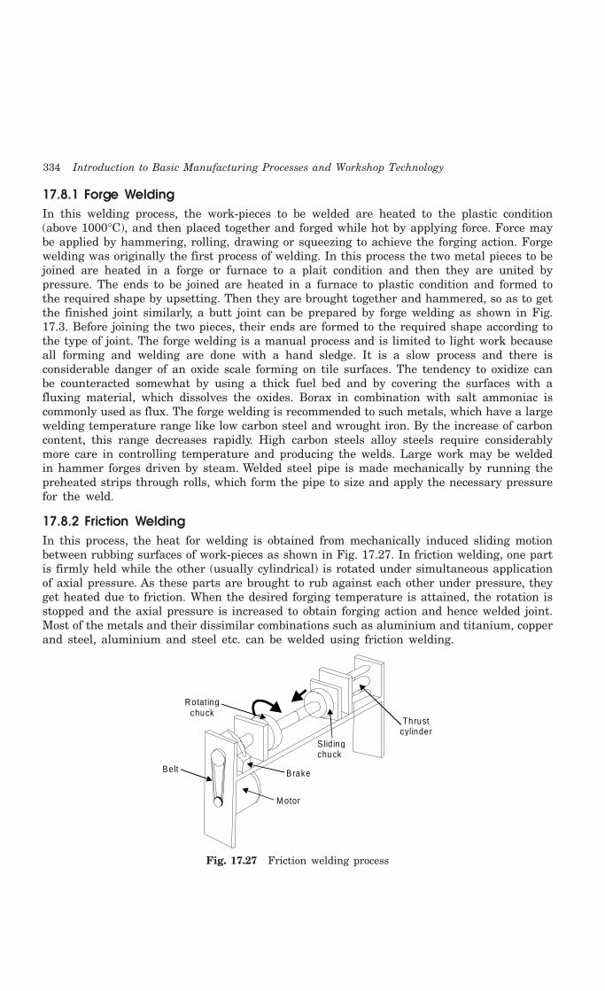
334 Introduction to Basic Manufacturing Processes and Workshop Technology
17.8.1 Forge WeldingIn this welding process, the work-pieces to be welded are heated to the plastic condition(above 1000°C), and then placed together and forged while hot by applying force. Force maybe applied by hammering, rolling, drawing or squeezing to achieve the forging action. Forgewelding was originally the first process of welding. In this process the two metal pieces to bejoined are heated in a forge or furnace to a plait condition and then they are united bypressure. The ends to be joined are heated in a furnace to plastic condition and formed tothe required shape by upsetting. Then they are brought together and hammered, so as to getthe finished joint similarly, a butt joint can be prepared by forge welding as shown in Fig.17.3. Before joining the two pieces, their ends are formed to the required shape according tothe type of joint. The forge welding is a manual process and is limited to light work becauseall forming and welding are done with a hand sledge. It is a slow process and there isconsiderable danger of an oxide scale forming on tile surfaces. The tendency to oxidize canbe counteracted somewhat by using a thick fuel bed and by covering the surfaces with afluxing material, which dissolves the oxides. Borax in combination with salt ammoniac iscommonly used as flux. The forge welding is recommended to such metals, which have a largewelding temperature range like low carbon steel and wrought iron. By the increase of carboncontent, this range decreases rapidly. High carbon steels alloy steels require considerablymore care in controlling temperature and producing the welds. Large work may be weldedin hammer forges driven by steam. Welded steel pipe is made mechanically by running thepreheated strips through rolls, which form the pipe to size and apply the necessary pressurefor the weld.
17.8.2 Friction WeldingIn this process, the heat for welding is obtained from mechanically induced sliding motionbetween rubbing surfaces of work-pieces as shown in Fig. 17.27. In friction welding, one partis firmly held while the other (usually cylindrical) is rotated under simultaneous applicationof axial pressure. As these parts are brought to rub against each other under pressure, theyget heated due to friction. When the desired forging temperature is attained, the rotation isstopped and the axial pressure is increased to obtain forging action and hence welded joint.Most of the metals and their dissimilar combinations such as aluminium and titanium, copperand steel, aluminium and steel etc. can be welded using friction welding.
Rotating chuck
S lid ingchuck
Thrust cylinder
Brake
M otor
Be lt
Fig. 17.27 Friction welding process

Welding 335
17.8.3 Explosive WeldingIn explosive welding, strong metallurgical bonds can be produced between metal combinationswhich cannot be welded by other methods or processes. For example, tantalum can beexplosively welded to steel although the welding point of tantalum is higher than thevaporization temperature of steel. Explosive welding process is shown in Fig. 17.28. It iscarried out by bringing together properly paired metal surfaces with high relative velocity ata high pressure and a proper orientation to each other so that a large amount of plasticinteraction occurs between the surfaces. The work piece, held fixed is called the target plateand the other called flyer plate. While a variety of procedures have been successfully employed,the main techniques of explosive welding can be divided into contact techniques and impacttechniques. In critical space and nuclear application, explosive welding permits fabrication ofstructures that cannot be made by any other means and, in some commercial applications,explosive joining is the least costly method. The main advantage of explosive welding includesthe simplicity of the process, and the extremely large surface that can be welded. Incompatiblematerials can also be bonded, and thin foils can be bonded to heavier plates.
D etonato r
Exp los ive
F lye r p late
Ta rget p late
A nv il
Bu ffe r p late
D e tonato r Exp los ive
F lye r p late
Ta rget p late
A nv il
Bu ffe r p late
α
(a) P ara lle l S tand O ff (b) A ngu lar S tand O ff
Fig. 17.28 Explosive welding process
17.9 THERMIT WELDING
It may be of forge or fusion kind of welding. Fusion welding requires no pressure. Thermitwelding process is depicted in Fig. 17.29. It is a process which uses a mixture of iron oxideand granular aluminium. This mixture in superheat liquid state is poured around the partsto be joined. The joint is equipped with the refractory mold structure all around. In case ofthermit pressure welding, only the heat of thermit reaction is utilized to bring the surfaceof metal to be welded in plastic state and pressure is the applied to complete the weld. Thetemperature produced in the thermit reaction is of the order of 3000°C. Thermit welding isused for welding pipes, cables, conductors, shafts, and broken machinery frames, rails andrepair of large gear tooth.
17.10 RADIANT ENERGY WELDING PROCESSES
In radiant energy welding processes, heat is produced at the point of welding when a streamof electrons or a beam of electro-magnetic radiations strikes on the workpiece. This weldingcan be carried out in vacuum or at low pressures. Electron beam welding (EBW) and laserwelding are two main types of radiant energy welding processes.
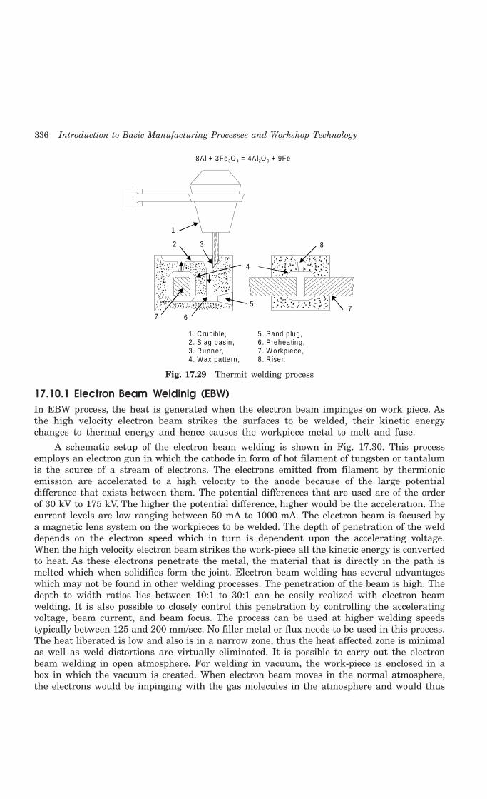
336 Introduction to Basic Manufacturing Processes and Workshop Technology
1
2 3
4
5
67
8
7
8Al + 3Fe O = 4Al O + 9Fe3 4 2 3
1 . C rucible,2 . S lag basin ,3 . Runner,4 . Wax pa tte rn ,
5 . Sand p lug,6 . Preheating,7 . W orkp iece ,8 . R iser.
Fig. 17.29 Thermit welding process
17.10.1 Electron Beam Weldinig (EBW)In EBW process, the heat is generated when the electron beam impinges on work piece. Asthe high velocity electron beam strikes the surfaces to be welded, their kinetic energychanges to thermal energy and hence causes the workpiece metal to melt and fuse.
A schematic setup of the electron beam welding is shown in Fig. 17.30. This processemploys an electron gun in which the cathode in form of hot filament of tungsten or tantalumis the source of a stream of electrons. The electrons emitted from filament by thermionicemission are accelerated to a high velocity to the anode because of the large potentialdifference that exists between them. The potential differences that are used are of the orderof 30 kV to 175 kV. The higher the potential difference, higher would be the acceleration. Thecurrent levels are low ranging between 50 mA to 1000 mA. The electron beam is focused bya magnetic lens system on the workpieces to be welded. The depth of penetration of the welddepends on the electron speed which in turn is dependent upon the accelerating voltage.When the high velocity electron beam strikes the work-piece all the kinetic energy is convertedto heat. As these electrons penetrate the metal, the material that is directly in the path ismelted which when solidifies form the joint. Electron beam welding has several advantageswhich may not be found in other welding processes. The penetration of the beam is high. Thedepth to width ratios lies between 10:1 to 30:1 can be easily realized with electron beamwelding. It is also possible to closely control this penetration by controlling the acceleratingvoltage, beam current, and beam focus. The process can be used at higher welding speedstypically between 125 and 200 mm/sec. No filler metal or flux needs to be used in this process.The heat liberated is low and also is in a narrow zone, thus the heat affected zone is minimalas well as weld distortions are virtually eliminated. It is possible to carry out the electronbeam welding in open atmosphere. For welding in vacuum, the work-piece is enclosed in abox in which the vacuum is created. When electron beam moves in the normal atmosphere,the electrons would be impinging with the gas molecules in the atmosphere and would thus
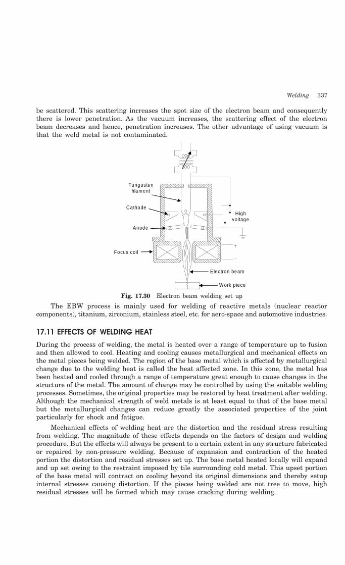
Welding 337
be scattered. This scattering increases the spot size of the electron beam and consequentlythere is lower penetration. As the vacuum increases, the scattering effect of the electronbeam decreases and hence, penetration increases. The other advantage of using vacuum isthat the weld metal is not contaminated.
Tungusten filament
Cathode
Anode
Focus coil
H igh voltage
Electron beam
W ork p iece
Fig. 17.30 Electron beam welding set up
The EBW process is mainly used for welding of reactive metals (nuclear reactorcomponents), titanium, zirconium, stainless steel, etc. for aero-space and automotive industries.
17.11 EFFECTS OF WELDING HEAT
During the process of welding, the metal is heated over a range of temperature up to fusionand then allowed to cool. Heating and cooling causes metallurgical and mechanical effects onthe metal pieces being welded. The region of the base metal which is affected by metallurgicalchange due to the welding heat is called the heat affected zone. In this zone, the metal hasbeen heated and cooled through a range of temperature great enough to cause changes in thestructure of the metal. The amount of change may be controlled by using the suitable weldingprocesses. Sometimes, the original properties may be restored by heat treatment after welding.Although the mechanical strength of weld metals is at least equal to that of the base metalbut the metallurgical changes can reduce greatly the associated properties of the jointparticularly for shock and fatigue.
Mechanical effects of welding heat are the distortion and the residual stress resultingfrom welding. The magnitude of these effects depends on the factors of design and weldingprocedure. But the effects will always be present to a certain extent in any structure fabricatedor repaired by non-pressure welding. Because of expansion and contraction of the heatedportion the distortion and residual stresses set up. The base metal heated locally will expandand up set owing to the restraint imposed by tile surrounding cold metal. This upset portionof the base metal will contract on cooling beyond its original dimensions and thereby setupinternal stresses causing distortion. If the pieces being welded are not tree to move, highresidual stresses will be formed which may cause cracking during welding.

338 Introduction to Basic Manufacturing Processes and Workshop Technology
The residual stresses also reduce load carrying capacity of the structure. The residualstresses may be relieved by heat treatment. Preheating the whole structure is helpful toreduce residual stresses. Certain procedures and proper welding sequences are also used inremoving the distortion and internal stress. It is to be noted that the flow of heat in the weldzone is highly directional towards the adjacent cold metal, which produces columnar grainsat right angle to the fusion line. The columnar structure is a characteristic of the metal ofsingle pass welds. Thus the original structure consisting of ferrite and pearlite in slabs ischanged to another microstructure. The composition of the first crystal which form a moltenalloy may quite different from the composition of the liquid, but as the freezing proceeds, thecrystals readjust their composition to that of the initial liquid alloy in order to satisfy thecondition of equilibrium. The weld metal when it is in the molten state can dissolve in oregases, which come into contact with it, like oxygen, nitrogen and hydrogen. But as the metalcools it looses its dissolving capacity and the dissolved gases become free from the metalcreating gas pockets and porosity in the final weld.
Welding processes widely used in the industry include oxy-acetylene, manual metal arcor shielded metal arc, submerged arc, gas metal arc, gas tungsten arc welding, resistancewelding, thermit welding and cold pressure welding. Most of these processes have specialfields of influence like resistance welding is popular with the automobile industry, thermitwelding for joining rails. Gas metal arc welding is particularly suited for welding of low carbonsteel structures as also welding of stainless steels and aluminium. It is more popular inaeronautical and nuclear industries. Submerged arc welding is used for ship building. Coldpressure welding is preferred by food processing industry. However, Arc welding and oxy-acetylene welding, processes are the general purpose processes with a wide range of applications.Some of the typical applications of welding include the fabrication of ships, pressure vessels,automobile bodies, off-shore platform, bridges, welded pipes, sealing of nuclear fuel and explosives,etc. The knowledge of welding is much essential to make welded fabrications a success.
17.12 WELDING DEFECTS
Defects in welding joints are given in 17.31 (i-viii)Lack of penetra tion
Lack of penetra tion
Fig. 17.31(i)
Lack of fusion
Lack of Fusion
Lack of fusion
Incom plete fus ion
Incom plete F usion
Fig. 17.31(ii)
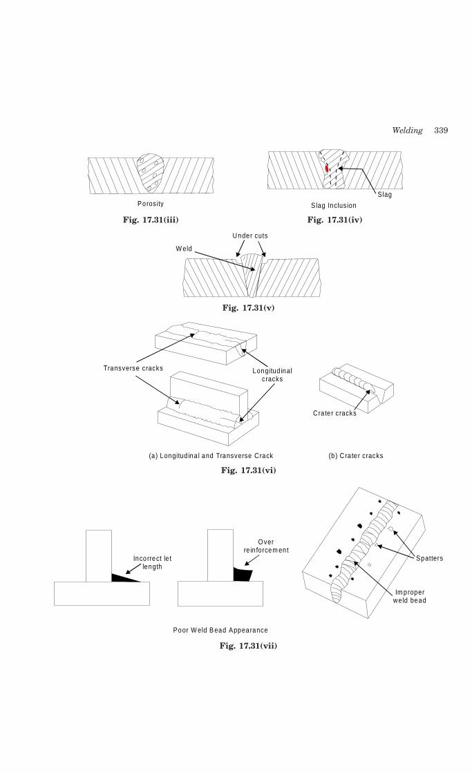
Welding 339
Porosity S lag Inclus ion
S lag
Fig. 17.31(iii) Fig. 17.31(iv)
W eld
Under cuts
Fig. 17.31(v)
Transverse cracks Longitud inal cracks
(a ) Longitud ina l and Transverse C rack
Cra te r cracks
(b) C ra te r cracks
Fig. 17.31(vi)
Incorrect le t length
O ver re in forcem ent
Poor W eld B ead Appearance
Im proper we ld bead
Spatters
Fig. 17.31(vii)
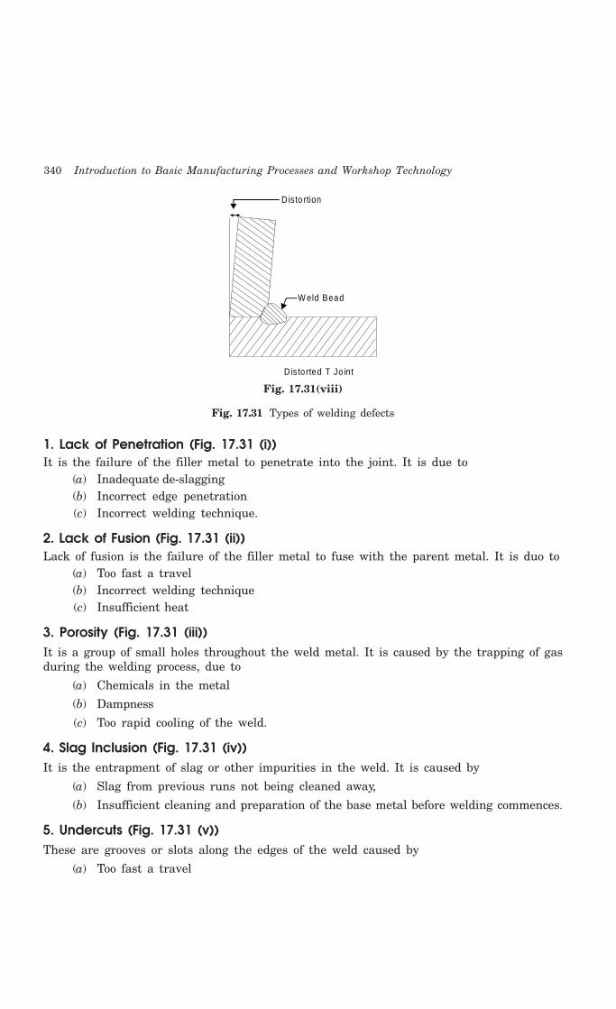
340 Introduction to Basic Manufacturing Processes and Workshop Technology
Disto rtion
W eld Bead
D isto rted T Jo int
Fig. 17.31(viii)
Fig. 17.31 Types of welding defects
1. Lack of Penetration (Fig. 17.31 (i))It is the failure of the filler metal to penetrate into the joint. It is due to
(a) Inadequate de-slagging(b) Incorrect edge penetration(c) Incorrect welding technique.
2. Lack of Fusion (Fig. 17.31 (ii))Lack of fusion is the failure of the filler metal to fuse with the parent metal. It is duo to
(a) Too fast a travel(b) Incorrect welding technique(c) Insufficient heat
3. Porosity (Fig. 17.31 (iii))It is a group of small holes throughout the weld metal. It is caused by the trapping of gasduring the welding process, due to
(a) Chemicals in the metal
(b) Dampness
(c) Too rapid cooling of the weld.
4. Slag Inclusion (Fig. 17.31 (iv))It is the entrapment of slag or other impurities in the weld. It is caused by
(a) Slag from previous runs not being cleaned away,
(b) Insufficient cleaning and preparation of the base metal before welding commences.
5. Undercuts (Fig. 17.31 (v))These are grooves or slots along the edges of the weld caused by
(a) Too fast a travel
Welding 341
(b) Bad welding technique
(c) Too great a heat build-up.
6. Cracking (Fig. 17.31 (vi))It is the formation of cracks either in the weld metal or in the parent metal. It is due to
(a) Unsuitable parent metals used in the weld
(b) Bad welding technique.
7. Poor Weld Bead Appearance (Fig. 17.31 (vii))If the width of weld bead deposited is not uniform or straight, then the weld bead is termedas poor. It is due to improper arc length, improper welding technique, damaged electrodecoating and poor electrode and earthing connections. It can be reduced by taking intoconsiderations the above factors.
8. Distortion (Fig. 17.31 (viii))Distortion is due to high cooling rate, small diameter electrode, poor clamping and slow arctravel speed
9. OverlaysThese consist of metal that has flowed on to the parent metal without fusing with it. Thedefect is due to
(a) Contamination of the surface of the parent metal
(b) Insufficient heat
10. BlowholesThese are large holes in the weld caused by
(a) Gas being trapped, due to moisture.
(b) Contamination of either the filler or parent metals.
11. Burn ThroughIt is the collapse of the weld pool due to
(a) Too great a heat concentration
(b) Poor edge preparation.
12. Excessive PenetrationIt is where the weld metal protrudes through the root of the weld. It is caused by
(a) Incorrect edge preparation
(b) Too big a heat concentration
(c) Too slow a travel.
17.13 BRAZING
Like soldering, brazing is a process of joining metals without melting the base metal. Fillermaterial used for brazing has liquidus temperature above 450°C and below the solidus

342 Introduction to Basic Manufacturing Processes and Workshop Technology
temperature of the base metal. The filler metal is drawn into the joint by means of capillaryaction (entering of fluid into tightly fitted surfaces). Brazing is a much widely used joiningprocess in various industries because of its many advantages. Due to the higher melting pointof the filler material, the joint strength is more than in soldering. Almost all metals can bejoined by brazing except aluminum and magnesium which cannot easily be joined by brazing.Dissimilar metals, such as stainless steel to cast iron can be joined by brazing. Because ofthe lower temperatures used there is less distortion in brazed joints. Also, in many cases theoriginal heat treatment of the plates being joined is not affected by the brazing heat. The jointcan be quickly finished without much skill. Because of the simplicity of the process it is oftenan economical joining method with reasonable joint strength. The brazed joints are reasonablystronger, depending on the strength of the filler metal used. But the brazed joint is generallynot useful for high temperature service because of the low melting temperature of the fillermetal. The color of the filler metal in the brazed joint also, may not match with that of thebase metal. Because the filler metal reaches the joint by capillary action, it is essential thatthe joint is designed properly. The clearance between the two parts to be joined should becritically controlled. Another important factor to be considered is the temperature at whichthe filler metal is entering the joint.
During brazing, the base metal of the two pieces to be joined is not melted. An importantrequirement is that the filler metal must wet the base metal surfaces to which it is applied.The diffusion or alloying of the filler metal with the base metal place even though the basemetal does not reach its solidus temperature. The surfaces to be joined must be chemicallyclean before brazing. However, fluxes are applied to remove oxides from the surfaces. Boraxis the most widely used flux during the process of brazing. It will dissolve the oxides of mostof the common metals.
17.13.1 Methods of Brazing
Torch BrazingIt is the most widely used brazing method. Heat is produced, generally, by burning a
mixture of oxy-acetylene gas, as in the gas welding. A carbonizing flame is suitable for thispurpose as it produces sufficiently high temperature needed for brazing.
Furnace BrazingIt is suitable for brazing large number of small or medium parts. Usually brazing filler
metal in the granular or powder form or as strips is placed at the joint, and then the assemblyis placed in the furnace and heated. Large number of small parts can be accommodated ina furnace and simultaneously brazed.
17.13.2 Braze WeldingIn welding processes where the joint of the base metal is melted and a joint is preparedhaving higher joint strength, it is likely to cause metallurgical damage by way of phasetransformations and oxide formation. In this process, the base metal is not melted, but thejoint is obtained by means of a filler metal.
17.14 SOLDERING
Soldering is a method of joining similar or dissimilar metals by heating them to a suitabletemperature and by means of a filler metal, called solder, having liquidus temperuatre not
Welding 343
exceeding 450°C and below the solidus of the base material. Though soldering obtains a goodjoint between the two plates, the strength of the joint is limited by the strength of the fillermetal used.
Solders are essentially alloys of lead and tin. To improve the mechanical properties andtemperature resistance, solders are added to other alloying elements such as zinc, cadmiumand silver in various proportions. Soldering is normally used for obtaining a neat leak proofjoint or a low resistance electrical joint. The soldered joints are not suitable for high temperatureservice because of the low melting temperatures of the filler metals used. The soldering jointsalso need to be cleaned meticulously to provide chemically clean surfaces to obtain a properbond. Solvent cleaning, acid pickling and even mechanical cleaning are applied before soldering.To remove the oxides from the joint surfaces and to prevent the filler metal from oxidizing,fluxes are generally used in soldering. Rosin and rosin plus alcohol based fluxes are leastactive type and are generally used for electrical soldering work. Because of the content ofacids, these are corrosive at soldering temperature. They can be easily cleaned after thesoldering. The organic fluxes such as zinc chloride and ammonium chloride are quick actingand produce efficient joints. But because of their corrosive nature the joint should be thoroughlycleaned of the entire flux residue from the joint. These are to be used for only non-electricalsoldering work. Fluxes are normally available in the form of powder, paste, liquid or in theform of core in the solder metal. It is necessary that the flux should remain in the liquid format the soldering temperature and be reactive to be of proper use.
The most commonly used soldering methods include soldering iron (flame or electricallyheated), dip soldering, and wave soldering. A soldering iron is a copper rod with a thin tipwhich can be used for flattening the soldering material. The soldering iron can be heated bykeeping in a furnace or by means of an internal electrical resistance whose power rating mayrange from 15 W for the electronic applications to 200 W for sheet metal joining. This is themost convenient method of soldering but somewhat slower compared to the other methods.In dip soldering, a large amount of solder is melted in a tank which is closed. The parts thatare to be soldered are first cleaned properly and dipped in a flux bath as per the requirement.These are then dipped into the molten solder pool and lifted with the soldering complete. Thewave soldering is a variant of this method wherein the part to be soldered (e.g.” an electronicprinted circuit board, PCB) is not dipped into the solder tank, but a wave is generated in thetank so that the solder comes up and makes a necessary joint.
17.14.1 Basic Operations in SolderingFor making soldered joints, following operations are required to be performed sequentially.
1. Shaping and fitting of metal parts togetherFiller metal on heating flows between the closely placed adjacent surfaces due to capillary
action, thus, closer the parts the more is solder penetration. This means that the two partsshould be shaped to fit closely so that the space between them is extremely small to be filledcompletely with solder by the capillary action. If a large gap is present, capillary action willnot take place and the joint will not be strong.
2. Cleaning of surfacesThis is done to remove dirt, grease or any other foreign material from the surface pieces
to be soldered, in order to get a sound joint. If surfaces are not clean, strong atomic bondswill not form.

344 Introduction to Basic Manufacturing Processes and Workshop Technology
3. Flux applicationSoldering cannot be done without a flux. Even if a metal is clean, it rapidly acquires an
oxide film of submicroscopic thickness due to heat and this film insulates the metal from thesolder, preventing the surface to get wetted by solder. This film is broken and removed bythe flux. The flux is applied when parts are ready for joining.
4. Application of heat and solderThe parts must be held in a vice or with special work holding devices so that they do
not move while soldering. The parts being soldered must be heated to solder-melting andsolder-alloying temperature before applying the solder for soldering to take place the assemblyso that the heat is most effectively transmitted to the being soldered.
As soon as the heat is applied, the flux quickly breaks down the oxide film (the insulatingoxide layer barrier between the surface and solder). Now solder is applied which immediatelymelts and metal to metal contact is established through the medium of molten solder. Finally,the surplus solder is removed and the joint is allowed to cool. Blow torches dipping the partsin molten solder or other methods are also used for soldering.
17.14.2 SoldersSolders are alloys of lead and tin. Solder may also contain certain other elements likecadmium, and antimony in small quantities. The percentage composition of tin and leaddetermines the physical and mechanical properties of the solder and the joint made. Mostsolder is available in many forms-bar, stick, fill, wire, strip, and so on. It can be obtained incircular or semi-circular rings or any other desired shape. Sometimes the flux is included withthe solder. For example, a cored solder wire is a tube of solder filled with flux.
17.14.3 Solder FluxesThe flux does not constitute a part of the soldered joint. Zinc chloride, ammonium chloride,and hydrochloric acid are the examples of fluxes commonly used in soldering. The functionof fluxes in soldering is to remove oxides and other surface compounds from the surfaces tobe soldered by displacing or dissolving them. Soldering fluxes may be classified into fourgroups-
(1) Inorganic fluxes (most active)
(2) Organic fluxes (moderately active)
(3) Rosin fluxes (least active), and
(4) Special fluxes for specific applications
17.15 QUESTIONS1. What is welding? How is it classified?
2. What are the advantages, disadvantages and applications of welding joints over other joints?
3. Explain the various types of joints commonly used in welding.
4. Explain the different kinds of welding positions with neat sketch.
5. Using neat sketch show the various standard location of elements of a welding symbol.
6. Classify the various welding processes in detail. Describe each in brief.
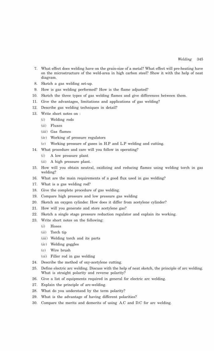
Welding 345
7. What effect does welding have on the grain-size of a metal? What effect will pre-heating haveon the microstructure of the weld-area in high carbon steel? Show it with the help of neatdiagram.
8. Sketch a gas welding set-up.
9. How is gas welding performed? How is the flame adjusted?
10. Sketch the three types of gas welding flames and give differences between them.
11. Give the advantages, limitations and applications of gas welding?
12. Describe gas welding techniques in detail?
13. Write short notes on :
(i) Welding rods
(ii) Fluxes
(iii) Gas flames
(iv) Working of pressure regulators
(v) Working pressure of gases in H.P and L.P welding and cutting.
14. What procedure and care will you follow in operating?
(i) A low pressure plant
(ii) A high pressure plant.
15. How will you obtain neutral, oxidizing and reducing flames using welding torch in gaswelding?
16. What are the main requirements of a good flux used in gas welding?
17. What is a gas welding rod?
18. Give the complete procedure of gas welding.
19. Compare high pressure and low pressure gas welding
20. Sketch an oxygen cylinder. How does it differ from acetylene cylinder?
21. How will you generate and store acetylene gas?
22. Sketch a single stage pressure reduction regulator and explain its working.
23. Write short notes on the following:
(i) Hoses
(ii) Torch tip
(iii) Welding torch and its parts
(iv) Welding goggles
(v) Wire brush
(vi) Filler rod in gas welding
24. Describe the method of oxy-acetylene cutting.
25. Define electric arc welding. Discuss with the help of neat sketch, the principle of arc welding.What is straight polarity and reverse polarity?
26. Give a list of equipments required in general for electric arc welding.
27. Explain the principle of arc-welding.
28. What do you understand by the term polarity?
29. What is the advantage of having different polarities?
30. Compare the merits and demerits of using A.C and D.C for arc welding.
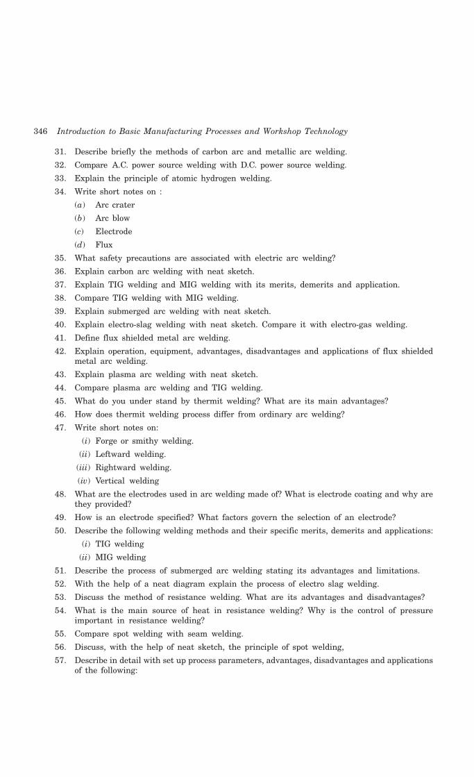
346 Introduction to Basic Manufacturing Processes and Workshop Technology
31. Describe briefly the methods of carbon arc and metallic arc welding.
32. Compare A.C. power source welding with D.C. power source welding.
33. Explain the principle of atomic hydrogen welding.
34. Write short notes on :
(a) Arc crater
(b) Arc blow
(c) Electrode
(d) Flux
35. What safety precautions are associated with electric arc welding?
36. Explain carbon arc welding with neat sketch.
37. Explain TIG welding and MIG welding with its merits, demerits and application.
38. Compare TIG welding with MIG welding.
39. Explain submerged arc welding with neat sketch.
40. Explain electro-slag welding with neat sketch. Compare it with electro-gas welding.
41. Define flux shielded metal arc welding.
42. Explain operation, equipment, advantages, disadvantages and applications of flux shieldedmetal arc welding.
43. Explain plasma arc welding with neat sketch.
44. Compare plasma arc welding and TIG welding.
45. What do you under stand by thermit welding? What are its main advantages?
46. How does thermit welding process differ from ordinary arc welding?
47. Write short notes on:
(i) Forge or smithy welding.
(ii) Leftward welding.
(iii) Rightward welding.
(iv) Vertical welding
48. What are the electrodes used in arc welding made of? What is electrode coating and why arethey provided?
49. How is an electrode specified? What factors govern the selection of an electrode?
50. Describe the following welding methods and their specific merits, demerits and applications:
(i) TIG welding
(ii) MIG welding
51. Describe the process of submerged arc welding stating its advantages and limitations.
52. With the help of a neat diagram explain the process of electro slag welding.
53. Discuss the method of resistance welding. What are its advantages and disadvantages?
54. What is the main source of heat in resistance welding? Why is the control of pressureimportant in resistance welding?
55. Compare spot welding with seam welding.
56. Discuss, with the help of neat sketch, the principle of spot welding,
57. Describe in detail with set up process parameters, advantages, disadvantages and applicationsof the following:

Welding 347
(i) Spot welding
(ii) Seam welding
(iii) Projection welding
(iv) Upset butt welding
(v) Flash butt welding
(vi) Percussion welding
58. Write short notes on following:
(i) Soldering
(ii) Brazing
(iii) Braze welding
59. Differentiate between soldering, brazing and welding.
60. Write short notes on:
(i) Electro-gas welding.
(ii) Stud welding.
(iii) Plasma arc welding.

348 Introduction to Basic Manufacturing Processes and Workshop Technology
348
SHEET METAL WORK
18.1 INTRODUCTION
Products made through the sheet metal processing include automobile bodies, utensils,almirah, cabinet’s appliances, electronic components, electrical parts, aerospace parts,refrigeration and air conditioning parts etc. Sheet metal is generally considered to be aplate with thickness less than about 5 mm. Articles made by sheet metal work are lessexpensive and lighter in weight. Sheet metal forming work started long back 5000 BC. Ascompared to casting and forging, sheet-metal parts offer advantages of lightweight andversatile shapes. Because of the good strength and formability characteristics, low carbonsteel is the most commonly utilized in sheet-metal processing work. The metal stampingshave now replaced many components, which were earlier made by casting or machining. Infew cases sheet metal products are used for replacing the use of castings or forgings. Sheetmetal work has its own significance in the engineering work. Sheet metal processing hasits own significance as a useful trade in engineering works to meet our day-to-dayrequirements. Many products, which fulfill the household needs, decoration work and variousengineering articles, are produced from sheet meta1s. A good product properly developedmay lead to saving of time and money.
In sheet-metal working, there is no need for further machining as required for castingand forging works. The time taken in sheet-metal working is approximately half of thatrequired in the machining process. For carrying out sheet metal work, the knowledge ofgeometry, mensuration and properties of metal is most essential because nearly all patternscome from the development of the surfaces of a number of geometrical models such ascylinder, prism, cone, and pyramid. In sheet metal work, various operations such as shearing,blanking, piercing, trimming, shaving, notching, forming, bending, stamping, coining,embossing etc. are to be performed on sheet metal using hand tools and press machines tomake a product of desired shape and size. Generally metals used in sheet metal work areblack iron, galvanized iron, stainless steel, copper, brass, zinc, aluminium, tin plate andlead.
18.2 METALS USED IN SHEET METAL WORK
The following metals are generally used in sheet metal work:
18CHAPTER

Sheet Metal Work 349
1. Black Iron SheetIt is probably the cheapest of all the metal used for sheet metal work. It is bluish
black in appearance and is used generally in form of uncoated sheet. It can be easilyrolled into the desired thickness. Since it is uncoated it corrodes rapidly. Hence toincrease its life it can be painted or enameled. This metal is generally used in themaking or roofs, food containers, stove pipes, furnace fittings, dairy equipments, tanks,cans and pans, etc.
2. Galvanized Iron (G.I.)It is popularly known as G.I. sheets. It is soft steel coated with molten zinc. This coating
resists rust formation on surface and improves appearance and water resistance. Articles suchas pans, furnaces, buckets, cabinets etc. are made from GI sheets.
3. Stainless SteelIt is an alloy of steel with nickel, chromium and small percentages of other metals. It
has good corrosion resistance. It is costlier but tougher than GI sheets. 1t is used in kitchenware,food processing equipments, food handling articles, tools and instruments for surgery workin hospitals and components of chemical plants etc.
Other metal sheets used for sheet metal work are made up of copper, aluminum, tin, andlead.
18.3 SHEET METAL TOOLS
The following tools are commonly used for sheet-metal work:
(i) Hand shears or snips
(ii) Hammers
(iii) Stakes and stake holder
(iv) Cutting tools
(v) Measuring tools
(vi) Miscellaneous hand tools such as chisels, groovers, seamers, rivet sets and hand punches.
Some of the important sheet metal tools are described as under.
18.3.1 HAND SHEARS OR SNIPSFig 18.1 shows the types of hand shears or snips. They resemble with pair of scissors
and are used like them to cut thin soft metal sheets of 20 gauge or thinner. They are requiredto size and shape the sheets. They can make straight or circular cuts. Different types of handshears are:
(1) Straight hand shear: It is used for general purpose cutting, making straight cutsand trimming away extra metal.
(2) Universal shear: Its blades are designed for universal cutting straight line orinternal and external cutting of contours. It may be of right hand or left hand type,easily identifiable, as the top blade is either on the right of on the left.
(3) Curved hand shear: It is used for cutting circular or irregular curved shapesranging from 20 to 35 cm.

350 Introduction to Basic Manufacturing Processes and Workshop Technology
Straigh t hand shear
Un iversal shear
Curved hand shear
Fig. 18.1 Types of hand shears or snips
18.3.2 HAMMERSFig 18.2 shows the various types of hammers used in sheet metal work for forming
shapes. The uses of different kind of hammers are given as under:
(a ) Sm ooth ing hamm er
(b ) S tretch ing ham mer
(c) C reasing ham m er
(d ) Ho llow ing ham mer
Hand le
(e ) R ive ting ham mer (f) P lanishing ham m er
Hand le
Hand le

Sheet Metal Work 351
(g ) B ossing m a lle t (i) Rawhide m alle t
(h ) Tinm en ’s m allet
Fig. 18.2 Types of hammers
(a) Smoothing hammer. Smoothing hammer (Fig. 18.3(a)) is used for leveling andsmoothing a sheet metal joint.
(b) Stretching hammer. Stretching hammer (Fig. 18.3(b)) is used for stretching sheet.
(c) Creasing hammer. Creasing hammer (Fig. 18.3(c)) is used to close down jointedges of sheets metal part.
(d) Hollowing hammer. Hollowing hammer (Fig. 18.3(d)) is used for hollowing sheetmetal part. It is used for generating sharp radii also.
(e) Riveting hammer. Riveting hammer (Fig. 18.3(e)) is used for forming riveted heads.
(f) Planishing hammer. Planishing hammer (Fig.18.3(f)) is used for removing smallmarks or indentations from the sheet metal job surface and to true the shape of thework. It smoothens off the finished sheet metal work.
(g) Soft hammer or Mallets. Mallets (Fig. 18.3(g)) used during working with soft metalsheets. They may be of wood, rubber or raw hide. A mallet strikes a blow with theminimum damage to the surface. In sheet metal work, the commonly used mallets arebossing mallet, tinman’s mallet (Fig. 18.3(h)) and rawhide mallet (Fig. 18.3(i)).
The uses of hammers for some sheet metal operations are depicted through Fig.18.3.
Using a creasing hamm er
(a )
Ho llow ing sheet m eta l
(b )
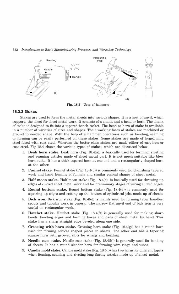
352 Introduction to Basic Manufacturing Processes and Workshop Technology
Rive ting
Hand le
Hand le
(c)
P lan ishing work
(d )
Fig. 18.3 Uses of hammers
18.3.3 StakesStakes are used to form the metal sheets into various shapes. It is a sort of anvil, which
supports the sheet for sheet metal work. It consists of a shank and a head or horn. The shankof stake is designed to fit into a tapered bench socket. The head or horn of stake is availablein a number of varieties of sizes and shapes. Their working faces of stakes are machined orground to needed shape. With the help of a hammer, operations such as bending, seamingor forming can be easily performed on these stakes. Some stakes are made of forged mildsteel faced with cast steel. Whereas the better class stakes are made either of cast iron orcast steel. Fig 18.4 shows the various types of stakes, which are discussed below:
1. Beak horn stake. Beak horn (Fig. 18.4(a)) is basically used for forming, rivetingand seaming articles made of sheet metal part. It is not much suitable like blowhorn stake. It has a thick tapered horn at one end and a rectangularly shaped hornat the other.
2. Funnel stake. Funnel stake (Fig. 18.4(b)) is commonly used for planishing taperedwork and hand forming of funnels and similar conical shapes of sheet metal.
3. Half moon stake. Half moon stake (Fig. 18.4(c) is basically used for throwing upedges of curved sheet metal work and for preliminary stages of wiring curved edges.
4. Round bottom stake. Round bottom stake (Fig. 18.4(d)) is commonly used forsquaring up edges and setting up the bottom of cylindrical jobs made up of sheets.
5. Bick iron. Bick iron stake (Fig. 18.4(e)) is mainly used for forming taper handles,spouts and tubular work in general. The narrow flat anvil end of bick iron is veryuseful on rectangular work.
6. Hatchet stake. Hatchet stake (Fig. 18.4(f)) is generally used for making sharpbends, bending edges and forming boxes and pans of sheet metal by hand. Thisstake has a sharp straight edge beveled along one side.
7. Creasing with horn stake. Creasing horn stake (Fig. 18.4(g)) has a round hornused for forming conical shaped pieces in sheets. The other end has a taperingsquare horn with grooved slots for wiring and beading.
8. Needle case stake. Needle case stake (Fig. 18.4(h)) is generally used for bendingof sheets. It has a round slender horn for forming wire rings and tubes.
9. Candle mold stake. Candle mold stake (Fig. 18.4(i)) has two horns for different taperswhen forming, seaming and riveting long flaring articles made up of sheet metal.

Sheet Metal Work 353
10. Blow horn stake. Blow horn stake (Fig. 18.4(j)) is generally used in forming,riveting and seaming tapered articles such as funnels.
11. Conductor stake. Conductor stake (Fig. 18.4(k)) has two cylindrical horns of differentdiameters. It is used for forming, riveting, and seaming small sized pipes and tubes.
12. Double seaming stake. Double seaming stake (Fig. 18.4(l)) consists of two cylindricalhorns of different diameters and it is commonly used for riveting forming, andseaming tubes and small pipes.
(a )(b )
(c)
(d )
(e )(f)
(g ) (h ) (i)
(j) (k)(l)
Fig. 18.4 Types of stakes
18.3.4 Stake HolderFig 18.5 shows the stake holder, which is a rectangular cast iron plate that has conveniently
arranged tapered holes so that the various stakes may fit in and may be used in differentpositions for tackling the sheet metal job for a particular work.
18.3.5 Cutting ToolsSheet metal shop uses cutting tools, which are described in detail in the chapter 19
pertaining to fitting work along with relevant figures. Commonly used cutting tools involve

354 Introduction to Basic Manufacturing Processes and Workshop Technology
types of files, chisels, scraper and hacksaws. Some of the commonly used cutting tools arediscussed as under.
1. Files. These are flat, square, round, triangular, knife, pillar, needle and mill types.
2. Chisels. The flat chisel and round nose chisel are most widely used in sheet metal work.
3. Scrapers. These are flat, hook; triangular, half round types.
4. Hacksaws. Hacksaw used in sheet metal shop may be hand hacksaw or powerhacksaw.
Stake holder
Fig. 18.5 Stake holder
18.3.6 Measuring ToolsThere are a fairly large number of measuring tools used in sheet metal shop, which are
described in detail along with relevant figures in chapter 19 dealing with fitting work. Themost commonly used measuring tools are given as under.
1. Folding rule
2. Circumference rule
3. Steel rule
4. Vernier caliper
5. Micrometer
6. Thickness gauge
18.3.7 Miscellaneous Hand Tools1. Steel square2. Straight edge3. Divider4. Scriber5. Trammel points6. Soldering iron7. Pliers
Some of the commonly used hand tools are described as under
1. Folding rule. It is used in measuring and laying out on sheets larger work withaccuracy of 0.5 mm.
2. Steel rule. It is useful in measuring and laying out small work on sheets. It canalso measure up to accuracy of 0.5 mm.
3. Tinrnan’s mandrel. The body of tinman’s mandrel consists of a flat part andcircular parts and serves as a base for carrying out several operations on sheets.The flat part carries a tapered square hole for accommodating the shanks of otherstacks. The circular part is required for seaming of pipes and riveting.
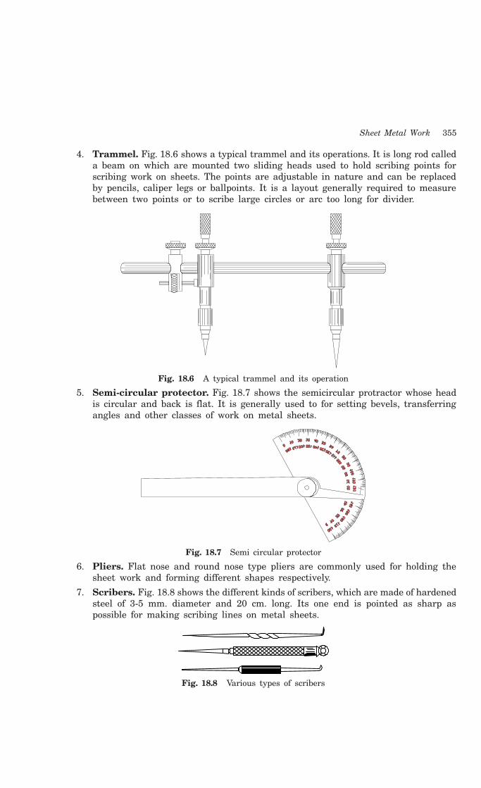
Sheet Metal Work 355
4. Trammel. Fig. 18.6 shows a typical trammel and its operations. It is long rod calleda beam on which are mounted two sliding heads used to hold scribing points forscribing work on sheets. The points are adjustable in nature and can be replacedby pencils, caliper legs or ballpoints. It is a layout generally required to measurebetween two points or to scribe large circles or arc too long for divider.
Fig. 18.6 A typical trammel and its operation
5. Semi-circular protector. Fig. 18.7 shows the semicircular protractor whose headis circular and back is flat. It is generally used to for setting bevels, transferringangles and other classes of work on metal sheets.
Fig. 18.7 Semi circular protector
6. Pliers. Flat nose and round nose type pliers are commonly used for holding thesheet work and forming different shapes respectively.
7. Scribers. Fig. 18.8 shows the different kinds of scribers, which are made of hardenedsteel of 3-5 mm. diameter and 20 cm. long. Its one end is pointed as sharp aspossible for making scribing lines on metal sheets.
Fig. 18.8 Various types of scribers
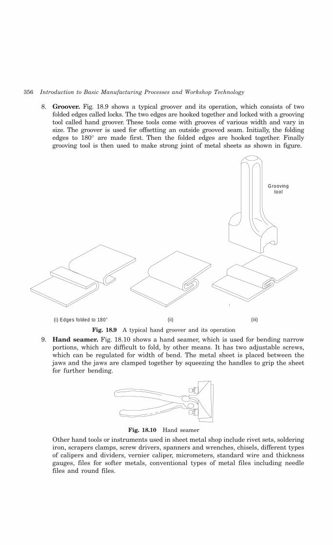
356 Introduction to Basic Manufacturing Processes and Workshop Technology
8. Groover. Fig. 18.9 shows a typical groover and its operation, which consists of twofolded edges called locks. The two edges are hooked together and locked with a groovingtool called hand groover. These tools come with grooves of various width and vary insize. The groover is used for offsetting an outside grooved seam. Initially, the foldingedges to 180° are made first. Then the folded edges are hooked together. Finallygrooving tool is then used to make strong joint of metal sheets as shown in figure.
G roovingtool
(i) Edges fo lded to 180 o (iii)(ii)
Fig. 18.9 A typical hand groover and its operation
9. Hand seamer. Fig. 18.10 shows a hand seamer, which is used for bending narrowportions, which are difficult to fold, by other means. It has two adjustable screws,which can be regulated for width of bend. The metal sheet is placed between thejaws and the jaws are clamped together by squeezing the handles to grip the sheetfor further bending.
Fig. 18.10 Hand seamer
Other hand tools or instruments used in sheet metal shop include rivet sets, solderingiron, scrapers clamps, screw drivers, spanners and wrenches, chisels, different typesof calipers and dividers, vernier caliper, micrometers, standard wire and thicknessgauges, files for softer metals, conventional types of metal files including needlefiles and round files.

Sheet Metal Work 357
18.4 FOLDING TERMINOLOGY OF SHEET METAL JOINT
18.4.1 EdgeThe edges on part need to be folded to increase the strength and to eliminate the sharp
edges of sheet metal component.
1. Types of folded edges. The common types of folded edges are: (i) single hem, (ii)double hem and (iii) wired edge
2. Single hem. It is made by folding the edge over. To layout such a hem, a line isdrawn at a distance equal to the desired hem width.
3. Double hem. It is a single hem with its end bent under. To layout such a hem,draw two parallel lines each equal to the width of the hem.
4. Wired edge. It consists of an edge, which has been wrapped around a piece of wire.This edge is used where more strength is needed. To layout wired edge the diameterof wire is to be determined. The steel metal will be needed to roll around the wire.
18.4.2 Seam A seam is the section where pieces of sheet metal are joined together. Most common
types of seams are:
(a) Single seam, (b) Double seam, (c) Grooved seam, (d) Lap seam, (e) Dovetail seam, and(f) Burred bottom seam
1. Single seam
It is used to join a bottom to vertical bodies of various shapes. To layout such a seam, drawa line parallel to one edge of the sheet metal body stretch out at a distance equal to the widthof the seam. Now draw two lines parallel to the edges of the bottom stretch out. The first lineshould be drawn at the distance from the edge of sheet metal equal to the width of the seamminus 1 mm. approx. Second line should be drawn at a distance from the first equal to thewidth to the seam on sheet metal plus 1 mm approx. The plus and minus dimensions of 1 mmis used to prevent the folded bottom edge of sheet metal from interfering with the body’s foldedbottom edge. If the bottom is round, then mark the lines on sheet metal part.
2. Double seam
The layout process for this seam on sheet metal part is similar to that used for a singleseam on sheet metal part. It differs from single seam in a manner that its formed edge isbent upward against the body.
3. Grooved seam
It is made by booking two folded edges of sheet metal part together and then off-settingthe seam as shown in Fig. 18.19. On one piece draw one line equal to half the width of theseam from outer edge. Then draw second line at a distance equal to the width of the seamfrom the first line. Same way draw two lines on the other piece of sheet metal part.
4. Lap seam
It is the simplest type of seam made on sheet metal part because one edge laps overanother and is soldered or riveted. To layout lap seam on sheet metal part, draw line on theedge of piece at a distance equal to the width of the required seam.
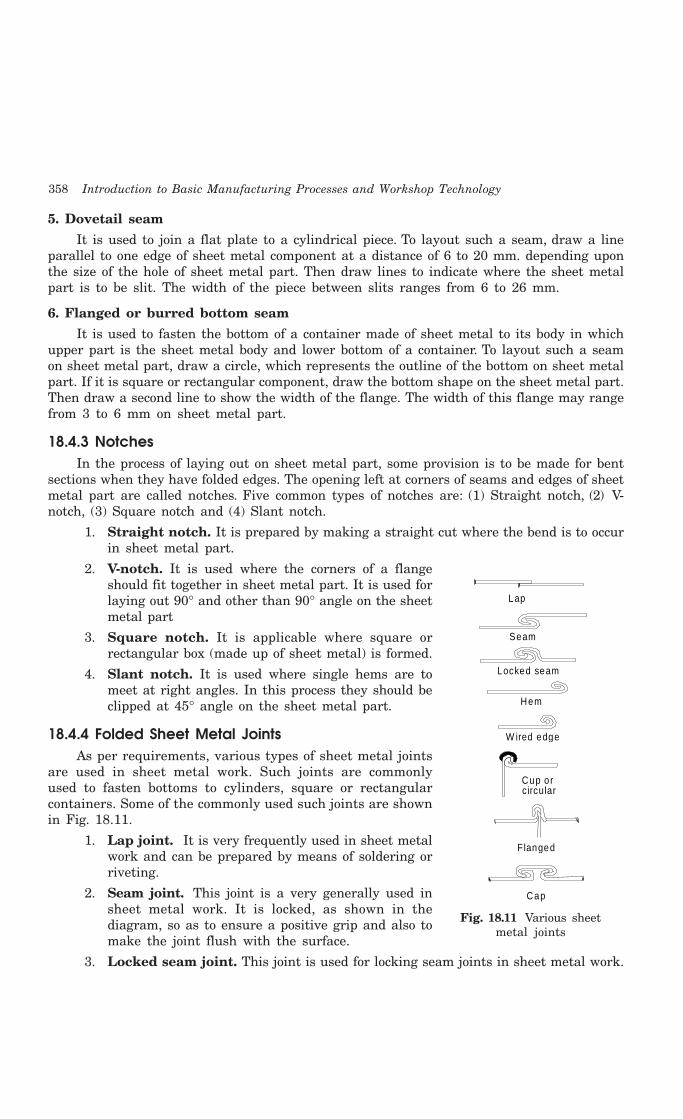
358 Introduction to Basic Manufacturing Processes and Workshop Technology
5. Dovetail seam
It is used to join a flat plate to a cylindrical piece. To layout such a seam, draw a lineparallel to one edge of sheet metal component at a distance of 6 to 20 mm. depending uponthe size of the hole of sheet metal part. Then draw lines to indicate where the sheet metalpart is to be slit. The width of the piece between slits ranges from 6 to 26 mm.
6. Flanged or burred bottom seam
It is used to fasten the bottom of a container made of sheet metal to its body in whichupper part is the sheet metal body and lower bottom of a container. To layout such a seamon sheet metal part, draw a circle, which represents the outline of the bottom on sheet metalpart. If it is square or rectangular component, draw the bottom shape on the sheet metal part.Then draw a second line to show the width of the flange. The width of this flange may rangefrom 3 to 6 mm on sheet metal part.
18.4.3 NotchesIn the process of laying out on sheet metal part, some provision is to be made for bent
sections when they have folded edges. The opening left at corners of seams and edges of sheetmetal part are called notches. Five common types of notches are: (1) Straight notch, (2) V-notch, (3) Square notch and (4) Slant notch.
1. Straight notch. It is prepared by making a straight cut where the bend is to occurin sheet metal part.
2. V-notch. It is used where the corners of a flangeshould fit together in sheet metal part. It is used forlaying out 90° and other than 90° angle on the sheetmetal part
3. Square notch. It is applicable where square orrectangular box (made up of sheet metal) is formed.
4. Slant notch. It is used where single hems are tomeet at right angles. In this process they should beclipped at 45° angle on the sheet metal part.
18.4.4 Folded Sheet Metal JointsAs per requirements, various types of sheet metal joints
are used in sheet metal work. Such joints are commonlyused to fasten bottoms to cylinders, square or rectangularcontainers. Some of the commonly used such joints are shownin Fig. 18.11.
1. Lap joint. It is very frequently used in sheet metalwork and can be prepared by means of soldering orriveting.
2. Seam joint. This joint is a very generally used insheet metal work. It is locked, as shown in thediagram, so as to ensure a positive grip and also tomake the joint flush with the surface.
3. Locked seam joint. This joint is used for locking seam joints in sheet metal work.
Lap
Seam
Locked seam
Hem
W ired edge
Cup or c ircular
Flanged
Cap
Fig. 18.11 Various sheetmetal joints

Sheet Metal Work 359
4. Hem (single and double), wired edge, cup and angular joints. These enablethe edges sheet metal part to join the pieces along them.
5. Flanged joint. It is commonly used in sheet metal work frequently in making pipeconnections.
6. Cap joint. It provides another useful form of locked seam joint on sheet metalcomponent with good appearance and strength. It is generally used for assemblingcross seam of ducts made up of in sheet metal part.
18.5 SHEET METAL OPERATIONS
The major sheet metal operations carried out in sheet metal work are as follows:
1. Cleaning 2. Measuring
3. Marking 4. Laying out
5. Hand cutting 6. Hand shearing
7. Hand forming 8. Edge forming
9. Wiring 10. Joint making
11. Bending 12. Drawing
13. Soldering 14. Circle cutting
15. Machine shearing 16. Nibbling
17. Piercing 18. Blanking
The measuring and marking operations carried over on sheet metal are discussed asunder.
Measuring and MarkingThe standard sizes of metal sheets available in the market are quite large. But the
required sheet size for making a component may be smaller and hence a standard size sheetmay have to be therefore cut into several smaller pieces. Each piece must be sufficient formaking one such component as per the needed size. Smaller sizes of sheet metal part are firstdecided and are then marked on the larger metal sheet to cut the latter into small piecesalong the marked lines. A little allowance for cutting is always incorporated to the requiredoverall sizes. The overall dimensions of the required smaller sizes are marked on the largersheet with the help of marking tools such as a steel rule, a straight edge, a steel square anda scriber. The sheet surface may have to be coated with a coloring media so that the scribedlines arc clearly visible. If circular pieces are needed, a divider or trammel may be used tomark the circles.
18.6 DEVELOMENT OF PATTERN LAYOUT
Projective geometry forms the basis of successful layout of patterns for making differentjobs in sheet metal work. Most of the patterns are obtained from development of surfaces ofsome common geometrical solids like cylinder, prism, pyramid and cone. These shapes maybe required to be developed either in single or in combination. A sheet metal planner shouldhave a thorough idea of the procedures employed in developing the surfaces of the abovesolids and their inter-penetrations.
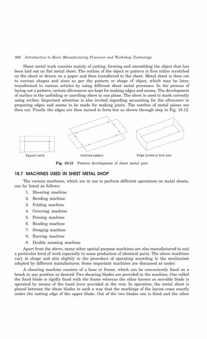
360 Introduction to Basic Manufacturing Processes and Workshop Technology
Sheet metal work consists mainly of cutting, forming and assembling the object that hasbeen laid out on flat metal sheet. The outline of the object or pattern is first either scratchedon the sheet or drawn on a paper and then transferred to the sheet. Metal sheet is then cutto various shapes and sizes as per the pattern or shape of object, which may be later,transformed to various articles by using different sheet metal processes. In the process oflaying out a pattern, certain allowances are kept for making edges and seams. The developmentof surface is the unfolding or unrolling sheet in one plane. The sheet is used to mark correctlyusing scriber. Important attention is also invited regarding accounting for the allowance inpreparing edges and seams to be made for making joints. The notches of metal pieces arethen cut. Finally the edges are then turned to form box as shown through step in Fig. 18.12.
Square no tch Edge tu rned to fo rm pan Notched pa tte rn
Fig. 18.12 Pattern development of sheet metal part
18.7 MACHINES USED IN SHEET METAL SHOP
The various machines, which are in use to perform different operations on metal sheets,can be listed as follows:
1. Shearing machine
2. Bending machine
3. Folding machine
4. Grooving machine
5. Peining machine
6. Beading machine
7. Swaging machine
8. Burring machine
9. Double seaming machine
Apart from the above, many other special purpose machines are also manufactured to suita particular kind of work especially in mass production of identical parts. The above machinesvary in shape and also slightly in the procedure of operating according to the mechanismadopted by different manufactures. Some important machines are discussed as under.
A shearing machine consists of a base or frame, which can be conveniently fixed on abench in any position as desired. Two shearing blades are provided in the machine. One calledthe fixed blade is rigidly fixed with the frame whereas the other known as movable blade isoperated by means of the hand lever provided at the rear. In operation, the metal sheet isplaced between the shear blades in such a way that the markings of the layout come exactlyunder the cutting edge of the upper blade. Out of the two blades one is fixed and the other

Sheet Metal Work 361
moveable. When the lever is pulled by the operator the lower blade rises and thus the metalsheet is cut. This particular provision enables the metal sheet to be locked against the upperblade during the operation on account of the circular motion of the hand lever. With theresult, the metal sheet is prevented from being distorted.
Folding machines are used for bending and folding the edges of metal plates to formthe joint at the seam. Bending machines or bending rollers, as they are better known, areused for shaping metal sheets into cylindrical objects. The machine consists of three rollers.These rollers have different adjustments indifferent types of machines. In some-machinestwo rollers at the bottom have fixed position and the third one (top roller) can be adjustedin vertical direction to adjust the pressure and give the required curvature to the sheet.A still better control is obtained by having two rollers exactly one over the other, out ofwhich the bottom roller is fixed and the top roller can be adjusted vertically to suit thethickness of the sheet and the pressure required for rolling. The third roller, called radiusroller can be moved up and down to provide the desired curvature. Improved designs ofthese machines are available which contain the rollers, which have grooves of variousshapes and sizes to form corresponding shapes in metal sheets. Conical shaped rollers areused for tapered cylindrical articles. Similarly other machines named above are used toperform different operations after which they are named.
Burring machine is used to make a burr on the edges of the bottom and covers. Burris the starting of the seam. Double seaming machine is used for double seaming flat bottomson straight or flared cylindrical pieces.
Various types of press machines with different capacities are used for mass productionof sheet metal components. These are equipped with different kind of press tools or dies.These are commonly employed for fast and accurate processing of sheet metal work.
18.8 TYPE OF PRESSES
Presses are classified based upon the method of operation method of power sourcemethod of activation of slide and number of slides in action. The sub-classification of each isalso gien as under.
1. Method of Operation(i) Arbor Press. It is a hand operated press. It combines the principle of lever with
pinions to a related rack build into the ram. They are used where a very limitedno. of production of parts is required.
(ii) Foot Press. It is also manual operated press. Most of the presses have foot actionin their operating mechanism.
(iii) Open back inclinable press. It is a power operated press. They are having benchor floor models.
Presses are classified according to
2. Method of Power Sources(i) Manual presses
(ii) Mechanical power presses
(iii) Hydraulic presses.
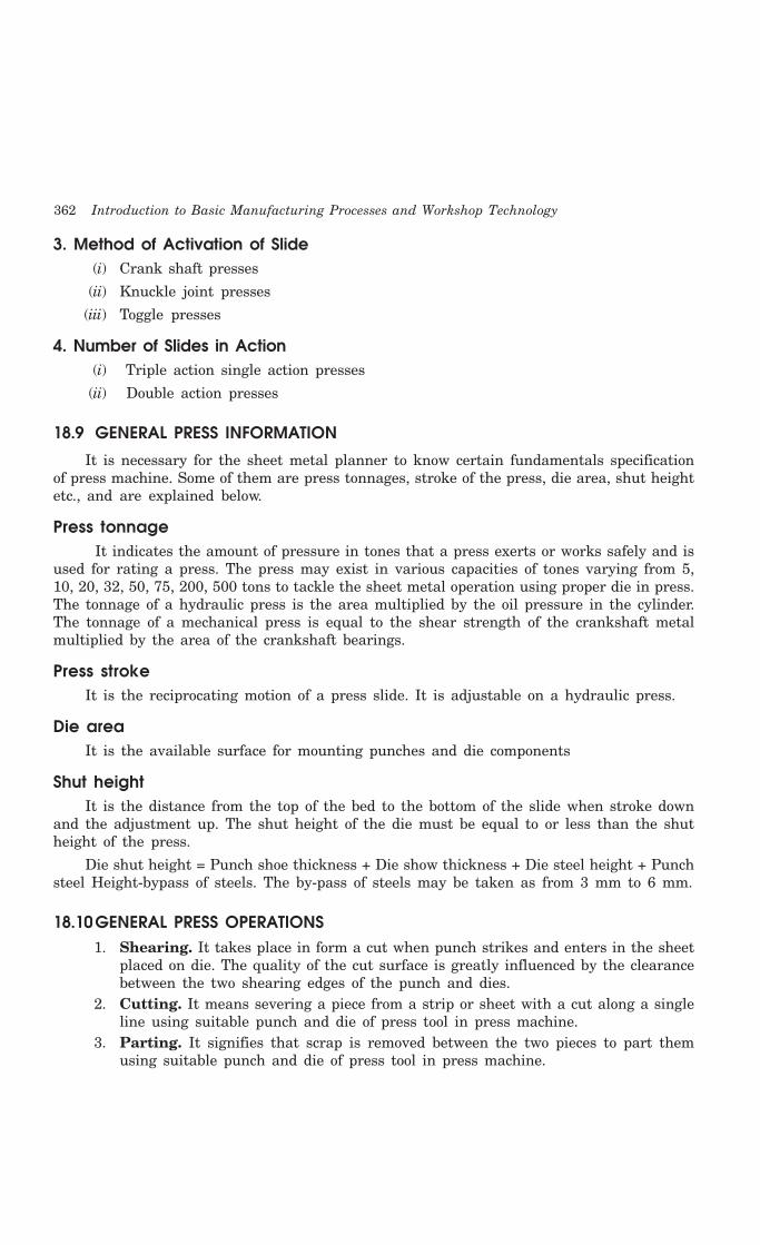
362 Introduction to Basic Manufacturing Processes and Workshop Technology
3. Method of Activation of Slide(i) Crank shaft presses
(ii) Knuckle joint presses
(iii) Toggle presses
4. Number of Slides in Action(i) Triple action single action presses
(ii) Double action presses
18.9 GENERAL PRESS INFORMATION
It is necessary for the sheet metal planner to know certain fundamentals specificationof press machine. Some of them are press tonnages, stroke of the press, die area, shut heightetc., and are explained below.
Press tonnageIt indicates the amount of pressure in tones that a press exerts or works safely and is
used for rating a press. The press may exist in various capacities of tones varying from 5,10, 20, 32, 50, 75, 200, 500 tons to tackle the sheet metal operation using proper die in press.The tonnage of a hydraulic press is the area multiplied by the oil pressure in the cylinder.The tonnage of a mechanical press is equal to the shear strength of the crankshaft metalmultiplied by the area of the crankshaft bearings.
Press strokeIt is the reciprocating motion of a press slide. It is adjustable on a hydraulic press.
Die areaIt is the available surface for mounting punches and die components
Shut heightIt is the distance from the top of the bed to the bottom of the slide when stroke down
and the adjustment up. The shut height of the die must be equal to or less than the shutheight of the press.
Die shut height = Punch shoe thickness + Die show thickness + Die steel height + Punchsteel Height-bypass of steels. The by-pass of steels may be taken as from 3 mm to 6 mm.
18.10GENERAL PRESS OPERATIONS1. Shearing. It takes place in form a cut when punch strikes and enters in the sheet
placed on die. The quality of the cut surface is greatly influenced by the clearancebetween the two shearing edges of the punch and dies.
2. Cutting. It means severing a piece from a strip or sheet with a cut along a singleline using suitable punch and die of press tool in press machine.
3. Parting. It signifies that scrap is removed between the two pieces to part themusing suitable punch and die of press tool in press machine.
Sheet Metal Work 363
4. Blanking. It is a operation in which the punch removes a portion of material calledblank from the strip of sheet metal of the necessary thickness and width usingsuitable punch and die of press tool in press machine.
5. Punching. It is the operation of producing circular holes on a sheet metal by apunch and die. The material punched out is removed as waste. Piercing, on theother hand, is the process of producing holes of any desired shape in the part orsheet using suitable punch and die of press tool in press machine.
6. Notching. It is a process to cut a specified shape of metal from the side or edgeof the stock using suitable punch and die.
7. Slitting. When shearing is conducted along a line, the process is referred to asslitting. It cuts the metal sheet lengthwise using suitable punch and die of press toolin press machine.
8. Lancing. It makes a cut part way across a sheet and creates a bend along the cutusing suitable punch and die.
9. Nibbling. It is an operation of cutting any shape from sheet metal without specialtools. It is done on a nibbling machine.
10. Trimming. It is the operation of cutting away excess metal in a flange or flash froma sheet metal part using suitable punch and die of press tool in press machine.
11. Bending. Bending is the operation of deforming a sheet around a straight axis. Theneutral plane lies on this straight axis. In bending all sheet material are stressedbeyond the elastic limit in tension on the outside and in compression on the insideof the bend. There is only one line, the natural line that retains its original length.The neutral axis lies at a distance of 30 to 50% of thickness of the sheet from theinside of the bend. Stretching of the sheet metal on the outside makes the stockthinner. Bending is sometimes called as forming, which involves angle bending, rollbending, roll forming, seaming and spinning.
18.11QUESTIONS
1. Explain various hand tools used in sheet metal work?
2. Name the metals commonly used in sheet metal work.
3. Write short notes on:
(a) Punching (b) Piercing
(c) Blanking (d) Slitting
(e) Bending (f) Lancing
4. Discuss the different sheering operations performed on sheet metal.
5. Explain the difference between punching, blanking and piercing.
6. Discuss the various types of hammers used in sheet metal work.
7. Describe the process of bending.
8. Write short notes on:
(a) Drawing (c) Shearing
(d) Riveting (e) Hollowing
(f) Planishing
9. Name various tools, machine and equipments used in sheet metal shop.
364 Introduction to Basic Manufacturing Processes and Workshop Technology
364
FITTING
19.1 INTRODUCTION
These days small, medium and heavy industries are using automatic machines. Butbench and fitting work also plays a significant role for completing and finishing a job to thedesired accuracy. Most of semi-finished works can be accomplished with fairly good degree ofaccuracy in a reasonable time through various kinds of quick machining operations. They stillrequire some minor operations to be performed to finish the job by hand. The term benchwork denotes the production of an article by hand on the bench. Where as fitting is theassembling of parts together and removing metals to secure the necessary fit, and may ormay not be carried out at the bench. These two types of work require the use of a largenumber of hand tools and other devices or equipments that involve a number of operationsfor accomplishing the work to the desired shape and size. Some of the commonly used toolsare discussed as under.
19.2 TOOLS USED IN FITTING SHOP
Tools used in bench and fitting shop are classified as under.
1. Marking tools
2. Measuring devices
3. Measuring instruments
4. Supporting tools
5. Holding tools
6. Striking tools
7. Cutting tools
8. Tightening tools, and
9. Miscellaneous tools
The above mentioned tools are further classified and discussed as under.
1. Markeing ToolsThese are sub classified as steel rule, circumference rule, straight edge, flat steel square,
19CHAPTER

Fitting 365
scriber, semi-circular protractor, divider, trammel, prick punch, centre punch, try square,bevel square, vernier protractor, combination set and surface gauge.
2. Measuring DevicesCommonly used measuring devices and instruments used in bench and fitting shop are
fillet and radius gauge, screw pitch gauge, surface plate, try square, dial gauge, feeler gauge,plate gauge and wire gauge.
3. Measuring InstrumentsLine measuring and end measuring devices. While using line measuring device, the
ends of a dimension being measured are aligned with the graduations of the scale from whichthe length is read directly such as scales or steel rules. Whereas, with end measuring device,the measurement is taken between two ends as in a micrometer, vernier calipers and gaugeblock, etc. End measuring devices are commonly used for measuring accurate and precisiondimensions of components. Some measuring instruments are employed for measuring lineardimensions and others are suitable for determining angular or geometric dimensions. Fewmeasuring instruments are also kept for reference purposes as standards of comparison. Themain measuring instruments are listed as under.
(i) Linear measurements
(A) Non-precision instruments
1. Steel rule
2. Calipers
3. Dividers
4. Telescopic gauge
5. Depth gauge
(B) Precision instruments
1. Micrometers
2. Vernier calipers
3. Vernier depth gauges
4. Vernier height gauges
5. Slip gauges
(C) Comparators
(D) Coordinate measuring machines
(ii) Angular measurements
(A) Non-precision instruments
1. Protector
2. Engineers square
3. Adjustable bevel
4. Combination set

366 Introduction to Basic Manufacturing Processes and Workshop Technology
(B) Precision instruments1. Bevel protector5. Angle gauges6. Sine bar7. Clinometers8. Autocollimators9. Sprit level
(iii) Surface measurement1. Straight edge2. Surface gauge3. Surface table4. Optical flat5. Profilo-meter
4. Supporting ToolsThese are vee-block, marking table, surface plate, and angle plate.
5. Holding ToolsThese are vices and clamps. Various types of vices are used for different purposes. They
include hand vice, bench vice, leg vice, pipe vice, and pin vice. The clamps are also of differenttypes such as c or g clamp, plane slot, goose neck, double end finger, u-clamp, parallel jaw,and clamping block.
6. Strking ToolsThese are various types of hammers such as ball peen hammer; straight peen hammer;
cross-peen hammer; double face hammer; soft face hammer.
7. Cutting ToolsThese involve various types of files, scrapers, chisels, drills, reamers, taps, snip or shear
and hacksaws.
Files. There are different types of files such as flat, square, round, triangular, knife,pillar, needle and mill.
Scrapers. These are flat, hook, triangular, half round types.
Chisels. There are different types of chisels used in fitting work such as flat chisel, crosscut chisel, diamond point chisel, half round chisel, cow mouth chisel and side cutting chisel.
The other cutting tools are drills, reamers, taps, snips, hacksaws (hand hacksaw andpower hacksaw) etc.
8. Tightening ToolsThese are pliers and wrenches, which are sub classified as under.
Pliers. These are namely ordinary, needle nose, and special type.
Wrench. These are open single ended, open double ended, closed ended adjustable, ringspanner, offset socket, t- socket, box wrench, pipe wrench and allen wrench.

Fitting 367
9. Miscellaneous ToolsThese are die, drifts, counter sink tools, counter boring tools, spot facing bit and drill press.
Some of above mentioned important tools are discussed as under.
19.2.1 Measuring Tools
19.2.1.1 Steel Rule
Steel rule is generally employed for purpose of measuring rough dimensions and layingout them. It is always advisable to start measuring from 1 cm mark because the end of therule is generally worn out
19.2.1.2 Circumference Rule
It is commonly used for measuring or laying out or as a straight edge. The specialty inthis rule is that the circumference can be taken directly, below the diameter dimension.
19.2.1.3 Straight Edges
There are two types of straight edges namely four edge type (Fig. 19.1(a)) and bridge type(Fig. 19.1(b)) which are made of carbon tool steel and alloy steel. They are generally flatgraduated bar of steel with one longitudinal edge beveled. Straight edges come in variouslengths commonly varying from 2.5 mm up to one meter and above. They are mostly usedfor scribing long straight lines.
Four edges type (a)
Bridge type
(b)
Fig. 19.1 Straight edges
19.2.1.4 Flat Steel Squrae
It is a piece of flat hardened steel with graduations on either end. It is commonly usedfor marking lines in the perpendicular direction to any base line.
19.2.1.5 Scribers
Fig. 19.2 shows the various types of scribers, which are sometimes called the metalworker’s pencil. These are made up of high carbon steel and are hardened from the front edge.Scriber is used for scratching lines on the sheet metal during the process of laying out a job.
Fig. 19.2 Scribers

368 Introduction to Basic Manufacturing Processes and Workshop Technology
19.2.1.6 Bever Protractor
The bevel protector (Fig. 19.3) is an instrument used for testing and measuring angleswithin the limits of five minutes accuracy. The common components of this instrument arebase, disc which is fitted with a pivot at the centre and carries a datum line. On this pivotof the protector, the dial is allowed to rotate when the clamping nut is released. The otherunit clamps the blade rigidly to the dial. The blade can be moved lengthwise. Vernier scaleis also provided on the disc to take reading for accurate measurement. Dial is graduated indegrees over an arc.
Fine adjustm ent nut & screw
M ain scale
Pro tractor
Edge bar
Sector
Square
Slid ing b lade
Vern ie r sca le
Lock nu t
P
Fig. 19.3 Bevel protector
19.2.1.7 Divider
It is used for marking and drawing circle and arcs on sheet metal.
19.2.1.8 Trammel
Trammel is used for marking and drawing large circles or arcs, which are beyond thescope of dividers.
19.2.1.9 Prick PunchFig. 19.4 shows the prick punch, which is used for indentation marks. It is used to make
small punch marks on layout lines in order to make them last longer. The angle of prickpunch is generally ground to 30° or 40° whereas for centre punch it is kept 60 °or 90°.
Prick punch
Center punch
60° or 90°
Fig. 19.4 Typical prick and centre punch
19.2.1.10 Centre Punch
Fig. 19.4 shows the centre punch, which is used for locating centre for indentation markfor drilling purposes.

Fitting 369
19.2.1.11 Surface Gauge or Scribing Block
Fig. 19.5 illustrate the surface gauge which is a principalmarking tool used generally in the fitting and the machineshops. It is made in various forms and sizes. It consists of acast iron sliding base fitted with a vertical steel rod. The scriberor marker is positioned or set into an adjustable device usinga knurled nut at one end. The scriber can be loosened ortightened by means of the nut. The marker is used to set itat any desired inclination, moved to and fro inside the holeaccommodating it or adjust its height along the vertical pillar.It is commonly used in conjunction with either a surface plateor marking table. It is used for locating centres of round rodheld in V- block, describing straight lines on work held firmlyin its position by means of a suitable device like angle plateand also in drawing a number of lines parallel to a true surface.This device is a very simple form of surface gauge and it islargely being replaced by a more accurate instrument calleduniversal surface gauge.
19.2.1.12 Universal Surface Gauge
Fig. 19.6 shows the universal surface gauge, whichis an improved variety of the surface gauge simplescribing block. It is designed in such as way thatappreciably finer adjustments can be made very quickly.It consists of a cast base perfectly machined and groundat the top, bottom and all sides. The base of the gaugeusually carries a V-shaped slot at the bottom so as torender it suitable for use on round objects. Two guidepins are provided at the rear end of the base, whichcan be pressed down to project below the base of thegauge. These pins can also be used against the edge ofthe surface plate or any other finished surface forguiding the instrument during marking and scribingwork. A swivel bolt is provided at the top of the basein which the spindle is fitted. This spindle can be swungand locked in any desired position by means of theadjusting screw, which is provided with a knurled nutat its end for this purpose. For marking purposes, thescriber is fitted in an adjustable screw on the spindleand is capable of being adjusted at any inclination and height along the spindle. A rocker isprovided at the top of the base and it carries an adjusting screw at its rear end. Duringoperation, the spindle is secured in the swivel bolt and is set at a desired inclination. Theadjustable scriber is swiveled and set at approximately the required height. On bringing thepoint of the scriber at the exact correct height, finer adjustments are then made usingadjusting screw provided on the rocker. Therefore, this gauge is commonly employed forscribing parallel lines at desired heights from a plane surface, comparing the trueness of twosimilar heights, setting out a desired height and similar other operations, and forms anindispensable instrument of bench work.
Spindle
Base
Scriber
Fig. 19.5 A surface gauge or scribing block
Scriber
Sp indle
C lam p
C lam p screw
Pin Base
Pin
Fig. 19.6 A universal surface gauge
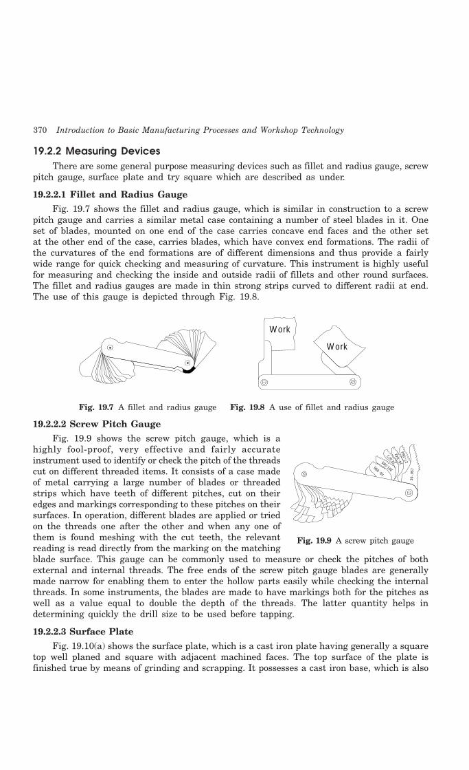
370 Introduction to Basic Manufacturing Processes and Workshop Technology
19.2.2 Measuring DevicesThere are some general purpose measuring devices such as fillet and radius gauge, screw
pitch gauge, surface plate and try square which are described as under.
19.2.2.1 Fillet and Radius Gauge
Fig. 19.7 shows the fillet and radius gauge, which is similar in construction to a screwpitch gauge and carries a similar metal case containing a number of steel blades in it. Oneset of blades, mounted on one end of the case carries concave end faces and the other setat the other end of the case, carries blades, which have convex end formations. The radii ofthe curvatures of the end formations are of different dimensions and thus provide a fairlywide range for quick checking and measuring of curvature. This instrument is highly usefulfor measuring and checking the inside and outside radii of fillets and other round surfaces.The fillet and radius gauges are made in thin strong strips curved to different radii at end.The use of this gauge is depicted through Fig. 19.8.
W ork
W ork
Fig. 19.7 A fillet and radius gauge Fig. 19.8 A use of fillet and radius gauge
19.2.2.2 Screw Pitch Gauge
Fig. 19.9 shows the screw pitch gauge, which is ahighly fool-proof, very effective and fairly accurateinstrument used to identify or check the pitch of the threadscut on different threaded items. It consists of a case madeof metal carrying a large number of blades or threadedstrips which have teeth of different pitches, cut on theiredges and markings corresponding to these pitches on theirsurfaces. In operation, different blades are applied or triedon the threads one after the other and when any one ofthem is found meshing with the cut teeth, the relevantreading is read directly from the marking on the matchingblade surface. This gauge can be commonly used to measure or check the pitches of bothexternal and internal threads. The free ends of the screw pitch gauge blades are generallymade narrow for enabling them to enter the hollow parts easily while checking the internalthreads. In some instruments, the blades are made to have markings both for the pitches aswell as a value equal to double the depth of the threads. The latter quantity helps indetermining quickly the drill size to be used before tapping.
19.2.2.3 Surface Plate
Fig. 19.10(a) shows the surface plate, which is a cast iron plate having generally a squaretop well planed and square with adjacent machined faces. The top surface of the plate isfinished true by means of grinding and scrapping. It possesses a cast iron base, which is also
3 0-.
0 57
27-.0
6426
-.042
22.07
2
201.0
85
16-.0
96
Fig. 19.9 A screw pitch gauge

Fitting 371
machined true to keep the top surface of the plate in a perfect horizontal plane. Its specificuse is in testing the trueness of a finished surface, testing a try square, providing adequatebearing surface for V-block (Fig. 19.10(b)) and angle plates, etc. in scribing work.
Face
Cast plate
Hand le
Cast base
Fig. 19.10(a) A surface plate
Surface p la te
V-B lock
Surface gage
Shaft
Fig. 19.10(b) A use of surface plate and v-block
19.2.2.4 Try Square
Fig. 19.11 shows the try square, which is also known asengineer’s try square. It is very important tool required forscribing straight lines at right angles to a true surface ortesting the trueness of mutually normal surfaces. It is madein different sizes out of steel pieces. In construction, it issimilar to a carpenter’s try square but is comparatively moreaccurate. It can be made either in one piece or in two pieces.It consists of a steel blade fitted into a steel stock of rectangularcross-section. It is sufficiently hardened and tempered to suitthe need. Some precision kind of try squares is made withtheir blades having beveled edges properly ground and finishedsquare. Both inner and outer surface of the blade are kept truly at right angles to thecorresponding surfaces of the stock. In order to maintain this trueness, this tool should behandled with due care and should never be used as a striking or supporting tool or otherwork. The accuracy of this tool should be frequently checked to ensure the trueness as itaffects the accuracy of the finished job to a significant extent.
For checking the accuracy or trueness of a try square, the try square is made to lie flaton the top surface of a surface plate with the stock touching a machined edge of the plate.A straight line is marked along the outer edge of the blade and then the square turned overto take a new position. Another straight line is described along the outer edge of the bladein this new position of the try square. If both lines coincide with each other as they seemsto be as one line only, then the try square can be said as true.
19.2.3 Measuring InstrumentsSome common measuring instruments generally used in bench work or fitting shop are
micrometer, vernier caliper, depth gauge, and vernier height gauge. These are discussed as under.
Beam
Blade
Fig. 19.11 A try square

372 Introduction to Basic Manufacturing Processes and Workshop Technology
19.2.3.1 Micrometers
The micrometers are commonly employed for measuring small dimensions with extremeaccuracy of 0.01 mm. They may be of the three kinds -
(a) External micrometer for measuring external dimensions,
(b) Internal micrometer for measuring internal dimensions, and
(c) Depth micrometer for measuring depths.
For measuring a dimension in external micrometer, the work piece is held between thefixed anvil face and the spindle face of the micrometer. The spindle of the micrometer isallowed to move linearly towards the work by rotating thimble. When the spindle will touchthe work piece properly, the ratchet will give its sound. The small locking lever is thenrotated to clamp the spindle so that reading can be taken more accurately. Outside micrometersare used for measuring the outside dimensions of jobs, such as diameter of a bar, rod andthickness of plate. Generally, until and unless they are provided with the vernier attachment,the former can read up to 1/1000 or 0.001 inch and the latter up to 0.01 mm. The former areknown as inches micrometers and the latter metric micrometers, which are gradually replacingthe former due to the introduction or adopting of metric system. Inside micrometers arecommonly used for measuring inside dimensions of the objects, such as inside dia. of a hole,width of a slot or cavity, etc. The outside micrometers are the most extensively used inindustrial applications. All the micrometers, irrespective of the fact as to whether they carrygraduations in inches or millimeters, are similar in construction. An out side micrometer isdiscussed as under.
OUTSIDE MICROMETERFig. 19.12 shows an outside micrometer. It consists of the following main parts.
1. Metallic frame2. Axial graduated sleeve3. Circumferential screwed spindle4. Hardened steel anvil5. Thimble6. Ratchet stop screw7. Lock nut
0 5 20
15
10
AnvilSp indle Lock
nutS leeve Th im b le Ratche t
s top
Fram eJob
Fig. 19.12 Outside micrometer
Micrometer works commonly on the principle of nut and bolt assembly. The sleevecarries inside threads at the end, which forms the nut, and the screwed part of the spindlepasses through it. The spindle and the thimble are secured to each other such that by rotating
Fitting 373
the thimble the spindle rotates. With the result, when the thimble is revolved, it advancestowards or retards away from the fixed anvil, together with the spindle of the micrometer.The sleeve carries the graduations, which, in conjunction with the beveled and graduated partof the thimble, give the measure of the opening between the end faces of the anvil and thespindle. The ratchet arrangement provided at the end of the thimble prevents the spindlefrom pressing further against the surface of the piece being measured after the required feelhas been attained, thus facilitating a uniform reading and preventing the instrument frombeing damaged. Lock nut or locking lever is used for locking the micrometer for a desiredamount of time after taking or setting the reading. The construction of the outside micrometeris discussed as under.
COMMON PARTS OF OUTSIDE MICROMETER(1) Frame. The U frame of micrometer is made of steel, cast steel, malleable cast iron
or light alloy.
(2) Hardened anvil. It protrudes from the frame for a distance of at least 3 mm forholding and supporting the jobs for measurement.
(3) Screwed spindle. It does the actual measuring and possesses threads of 0.5 mmpitch.
(4) Barrel or Sleeve. It has datum or fiducially line and fixed graduations.
(5) Thimble. This is a tubular cover fastened with the spindle and moves with thespindle. The beveled edge of the thimble is divided into 50 equal parts, every fifthbeing numbered.
(6) Ratchet. This part is commonly recognized as friction stop of the micrometer,which acts as a precautionary measure also. It is a small extension to the thimblein which the ratchet slips when the pressure on the screw exceeds a certain amount.This produces uniform reading and prevents any damage or distortion of theinstrument.
(7) Spindle clamp. It is used to lock the instrument at any desired setting or at anyparticular reading .
READING ON MICRO METERIt works on the fine assembly of nut and bolt principle where pitch of both nut and bolt playsa big role. The graduation on the barrel of micrometer is in two parts, namely one above thereference line and the other below. The higher line graduation above the reference line isgraduated in 1 mm intervals. The first and every fifth are long and numbered 0, 5, 10, 15,20 and 25. The lower or small graduations are graduated in mm intervals but each graduationshall be placed at the middle of the two successive upper graduations to be read 0.5 mm. Themicrometer screw has a pitch of 0.5 mm, while the thimble has a scale of 50 divisions roundits circumference. Thus, on making or rotating through one complete turn, the thimblemoves forward or backward by one thread pitch of 0.5 mm, and one division of its scale is,therefore, equivalent to a longitudinal movement of 0.5 × 1/50 mm = 0.01 mm. It is the valueof one division on the thimble, which is the least that can be correctly read with the help ofa micrometer and is known as the least count. For measurement, the job is kept betweenthe end of the spindle and the fixed anvil, which is fitted to the frame. When the micrometeris closed, the line marked 0 (zero) on the thimble coincides with the line marked 0 (zero) onthe graduated sleeve. In metric outside micrometer, the pitch of the spindle screw is 0.5 mm

374 Introduction to Basic Manufacturing Processes and Workshop Technology
and the graduations provided on the spindle of themicrometer are in millimeters and subdivided into0.5 mm. Now in one turn of the thimble of themicrometer, owing to the 0.5 mm. pitch of thespindle screw, the spindle will move through 0.5mm and therefore, the corresponding openingbetween the faces of the fixed anvil and the spindlewill be 0.5 mm. This opening will go on increasingby the same distance 0.5 mm for each furtherrotation of the thimble. The beveled edge of thethimble carries 50 equal divisions on its peripheryin which every 5th division is marked. It is seenabove that for one complete turn of the thimblethe spindle moves through 0.5 mm. Now let thethimble is rotated one small division on its bevelededge i.e. 1/50 of the turn. The correspondingdisplacement of the spindle will then be 0.5 × 1 /50 = 0.01mm.
Depth micrometer is used for measuring depth ofholes and is shown in Fig. 19.13. Screw threadmicrometer (Fig. 19.14) is used to measure the pitchdiameter of the thread to an accuracy of 0.01mmand 0.001 inches. It comprises of similar parts asthat of outside micrometer accept the shapes of fixedand moveable anvils. The fixed and moveable anvilspossess the thread profiles for thread adjustmentfor measurement of the pitch diameter.
Fig. 9.14 A screw thread micrometer
19.2.3.2 Steel Rule
It is the simplest measuring tool just like a scale used in fitting shop. A six inch semiflexible rule is shown in Fig. 19.15 Other types of rules are described in the chapter oncarpentry shop. Most of the dimensions are measured by the steel rule in workshops.
1 2 3 4 5
Fig. 9.15 A steel rule
Ratche t s top
Th im b le
Sleeve
Locking ring
Head
Spindle
Fig. 9.13 A depth micrometer

Fitting 375
19.2.3.3 Caliper
Calipers are generally of two types inside and outside to make internal or externalmeasurements. They do not have direct scale reading. They transfer the measurement fromjobs to scale or vice versa. Fig. 19.16 shows a simple outside caliper. The caliper is held ina rule as shown in Fig. 19.17 to read the size. It is used to make external measurement suchas thickness of plates, diameter of sphere and cylinders. Fig. 19.18 shows the standard springjoint outside caliper.
1 2 3 4
Fig. 9.16 A simple outside Fig. 9.17 A caliper held in rule Fig. 9.18 A standard spring caliper joint outside caliper
19.2.3.4 Vernier Caliper
Fig. 19.19 shows the vernier caliper, which is commonly used to measure accurately
(1) outside diameters of shafts,
(2) thicknesses of various parts,
(3) diameters of holes or rings and
(4) internal dimensions of hollow jobs or articles.
0 3 4 51
0 5 15 25
6
Fine adjustm ent clam p
M ain scale
Fine adjustm ent screw
Vern ie rS lid ing jaw
Fixed jaw
M easuring faceJob
Fig. 19.19 A vernier caliper
It works on the principle of vernier and can measure the dimensions to an accuracy of0.02 mm. For making a measurement of external dimensions, the job is placed between the

376 Introduction to Basic Manufacturing Processes and Workshop Technology
fixed and the movable jaws. The movable or the sliding jaw is moved until it almost contactsthe job kept against the fixed jaw. The sliding jaw assembly of the vernier caliper that carriesthe fine adjustment screw should be clamped to the graduated beam with the help of adjustmentclamp. The two jaws are then brought into contact with the job by moving the sliding jawwith the help of fine adjustment screw. The jaws should make now definite contact with thejob but should not be tight. The main slide assembly is then locked to the beam with helpof clamp. The caliper is then carefully removed from the job to prevent springing the jawsand the reading is taken. For making a measurement of internal dimensions, the job is placedoutward between the fixed and the movable jaws meant for measuring inner dimension.
19.2.3.5 Vernier Depth Gauge
Vernier depth gauge is basically employed for checking depths of blind holes such asgrooves, slots, depth of key ways and heights of shoulders, etc. The principle on which itworks is the same as that of a vernier caliper. It is available with similar measuring accuraciesas the vernier caliper and readings are taken the similar manner. It consists of a movablehead with a base, which moves along the beam. A main scale on the beam and vernier scaleon the sliding head with fine adjustment screw are incorporated in the similar manner as ina vernier caliper.
19.2.3.6 Vernier Height Gauge
Fig. 19.20 illustrates the vernier height gauge, which is employed for measuring theheight of parts and in precision marking work. It consists of a heavy base, an accuratelyfinished bottom, a vertical bar mounted square to the base, carrying the main scale, a slidinghead with vernier, an auxiliary head with fine adjustment screw and nut and a bracketattached to the sliding head. This bracket is provided with a clamp by means of whichinterchangeable jaws can be fixed over there. The jaws can be fixed for measuring height orreplaced by scribing jaws according to requirement or need. The graduations on the heightgauge are given in Fig. 19.21.
G uiding edge
Scale
Fine adjustm ent screw
C lam p
Beam
Base
Slider
Depth o f m easuring jaw
Lower face o f jaw
M easuring jaw
Scriber
Upper face o f jaw(M easuring face)
Fine adjustm ent c lamp
Vern ie r sca les
Slider clam ping screw
Fig. 19.20 A vernier height gauge
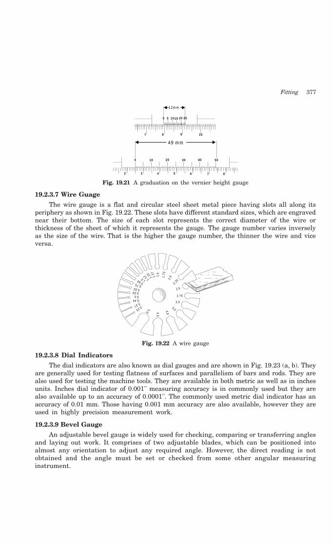
Fitting 377
0 10 20 30 40 50
2 3 4 5 6 7 8
0 5 10 20 25
7 8 9 10
15
1 2 m m
49 m m
Fig. 19.21 A graduation on the vernier height gauge
19.2.3.7 Wire Guage
The wire gauge is a flat and circular steel sheet metal piece having slots all along itsperiphery as shown in Fig. 19.22. These slots have different standard sizes, which are engravednear their bottom. The size of each slot represents the correct diameter of the wire orthickness of the sheet of which it represents the gauge. The gauge number varies inverselyas the size of the wire. That is the higher the gauge number, the thinner the wire and viceversa.
1.5
1.7 5
2 .0
2 .25
2.5
2 .7 5
3 .0
3.54.0
5.0
0.25
0.37
0.440.50.56
0.620.75 0.89 1.0 1.12 1.
25 1.37
4.5
Fig. 19.22 A wire gauge
19.2.3.8 Dial Indicators
The dial indicators are also known as dial gauges and are shown in Fig. 19.23 (a, b). Theyare generally used for testing flatness of surfaces and parallelism of bars and rods. They arealso used for testing the machine tools. They are available in both metric as well as in inchesunits. Inches dial indicator of 0.001" measuring accuracy is in commonly used but they arealso available up to an accuracy of 0.0001". The commonly used metric dial indicator has anaccuracy of 0.01 mm. Those having 0.001 mm accuracy are also available, however they areused in highly precision measurement work.
19.2.3.9 Bevel Gauge
An adjustable bevel gauge is widely used for checking, comparing or transferring anglesand laying out work. It comprises of two adjustable blades, which can be positioned intoalmost any orientation to adjust any required angle. However, the direct reading is notobtained and the angle must be set or checked from some other angular measuringinstrument.
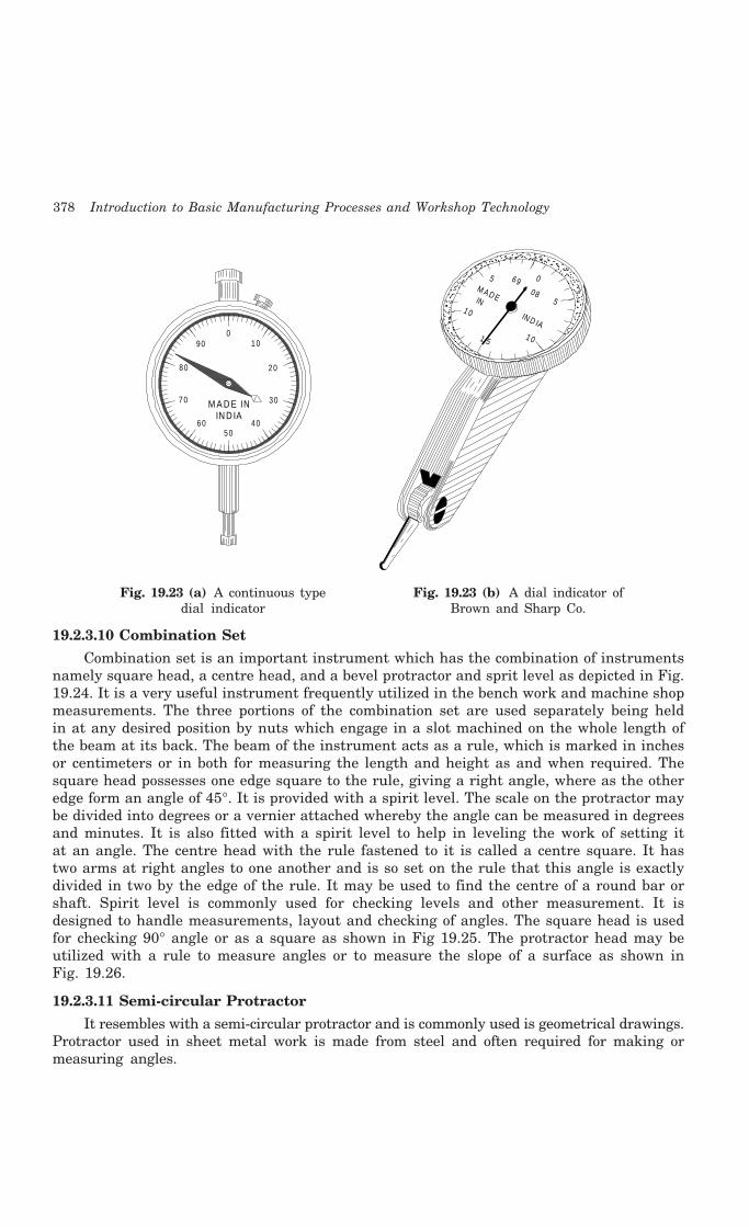
378 Introduction to Basic Manufacturing Processes and Workshop Technology
01 0
2 0
3 0
5 04 06 0
7 0
8 0
9 0
M A D E ININ D IA
1 0
5 0
1 5
6908
M A D E IN IN D IA
5
1 0
Fig. 19.23 (a) A continuous type Fig. 19.23 (b) A dial indicator ofdial indicator Brown and Sharp Co.
19.2.3.10 Combination Set
Combination set is an important instrument which has the combination of instrumentsnamely square head, a centre head, and a bevel protractor and sprit level as depicted in Fig.19.24. It is a very useful instrument frequently utilized in the bench work and machine shopmeasurements. The three portions of the combination set are used separately being heldin at any desired position by nuts which engage in a slot machined on the whole length ofthe beam at its back. The beam of the instrument acts as a rule, which is marked in inchesor centimeters or in both for measuring the length and height as and when required. Thesquare head possesses one edge square to the rule, giving a right angle, where as the otheredge form an angle of 45°. It is provided with a spirit level. The scale on the protractor maybe divided into degrees or a vernier attached whereby the angle can be measured in degreesand minutes. It is also fitted with a spirit level to help in leveling the work of setting itat an angle. The centre head with the rule fastened to it is called a centre square. It hastwo arms at right angles to one another and is so set on the rule that this angle is exactlydivided in two by the edge of the rule. It may be used to find the centre of a round bar orshaft. Spirit level is commonly used for checking levels and other measurement. It isdesigned to handle measurements, layout and checking of angles. The square head is usedfor checking 90° angle or as a square as shown in Fig 19.25. The protractor head may beutilized with a rule to measure angles or to measure the slope of a surface as shown inFig. 19.26.
19.2.3.11 Semi-circular Protractor
It resembles with a semi-circular protractor and is commonly used is geometrical drawings.Protractor used in sheet metal work is made from steel and often required for making ormeasuring angles.
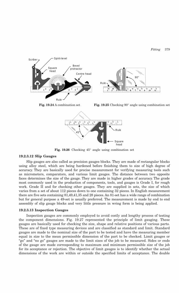
Fitting 379
3489
3 4 8 9
Ru le
Centre head
Square head
Beve l p rotracto r
Sp irit-levelScriber
1 2 3 4 5 6 7 10 11
1 2 3 5 6 7 8 9 10 11
90°
Ru le
Fig. 19.24 A combination set Fig. 19.25 Checking 90° angle using combination set
45°Ru le
Square head
Fig. 19.26 Checking 45° angle using combination set
19.2.3.12 Slip Gauges
Slip gauges are also called as precision gauges blocks. They are made of rectangular blocksusing alloy steel, which are being hardened before finishing them to size of high degree ofaccuracy. They are basically used for precise measurement for verifying measuring tools suchas micrometers, comparators, and various limit gauges. The distance between two oppositefaces determines the size of the gauge. They are made in higher grades of accuracy. The grademost commonly used in the production of components, tools, and gauges is Grade I, for roughwork. Grade II and for checking other gauges. They are supplied in sets, the size of whichvaries from a set of about 112 pieces down to one containing 32 pieces. In English measurementthere are five sets containing 81,49,41,35 and 28 pieces. An 81-set has a wide range of combinationbut for general purpose a 49-set is usually preferred. The measurement is made by end to endassembly of slip gauge blocks and very little pressure in wring form is being applied.
19.2.3.13 Inspection Gauges
Inspection gauges are commonly employed to avoid costly and lengthy process of testingthe component dimensions. Fig. 19.27 represented the principle of limit gauging. Thesegauges are basically used for checking the size, shape and relative positions of various parts.These are of fixed type measuring devices and are classified as standard and limit. Standardgauges are made to the nominal size of the part to be tested and have the measuring memberequal in size to the mean permissible dimension of the part to be checked. Limit gauges or“go” and “no go” gauges are made to the limit sizes of the job to be measured. Sides or endsof the gauge are made corresponding to maximum and minimum permissible size of the jobfor its acceptance or rejection. The objective of limit gauges is to identify whether the actualdimensions of the work are within or outside the specified limits of acceptance. The double

380 Introduction to Basic Manufacturing Processes and Workshop Technology
end kind of limit gauge has the GO portion at one end and the NO GO portion at the otherend. GO portion must pass into or over an acceptable piece but the NO GO portion shouldnot pass. Inspection gauges may be classified as working, inspection, and reference or mastergauges. The working and inspection gauges are generally employed for inspection of componentsfrom stage to stage.
G oNot go
Low lim it
H igh lim it
Shaft
Fig. 19.27 A principle of limit gauge
Reference or master gauges are needed only for checking the size or condition of othergauges. The gauges are generally classified into:
1. Gauges for checking shafts
2. Gauges for checking holes
3. Gauges for checking forms
4. Gauges for checking threads
5. Gauges for checking tapers
The gauges commonly used in production work are
1. Progressive or step plug gauge (Fig. 19.28(a))
2. Thread plug gauge (Fig. 19.28(b))
3. A combination of internal and external non adjustable gauges (Fig. 19.28(c))For O D
G o
Not G oG o
NotG o
IDFor
(a ) Progressive o r S tep p lug G auge.
(b ) Thread plug gauge.
(c) A com bina tion of in te rna l and externa l non-adjustable gauges
Fig. 19.28 Types of gauges

Fitting 381
4. Ring gauge
5. Snap gauges (Fig. 19.29)
No
Go
No G o G o Go
F ixed anvils
Ad justab le anvils
Fig. 19.29 Snap gauges
6. Feeler gauge (Fig. 19.30)
.010.008
.006
.004
.003 .002 .0015
.015
.012
H industanLO C
K
Fig. 19.30 A feeler gauge
7. Wire gauge8. Template gauge9. Adjustable gap gauge (Fig. 19.31)
10. Screw pitch gauge (Fig. 19.9)11. Fillet and radius gauge
G oFixed anvils
Ad justab le anvil
No t G o
Fig. 19.31 An adjustable gap gauge
For manufacturing the above gauges, high carbon and alloy steels materials are commonlyemployed for manufacturing or production of gauges. Steel gauges may be used subject tosome distortion during hardening. These difficulties can be overcome by making gauges byuse of cemented carbide material or providing chrome plating at the surface of the gauge.

382 Introduction to Basic Manufacturing Processes and Workshop Technology
Plug Gauges
These are used for checking cylindrical, tapered, threaded, splined and square holesportions of manufacture components.
19.2.4 Holding ToolsHolding tools used in fitting shop comprises of basically vices and clamps. The clamps are
C or G clamp, plane slot, goose neck, double end finger, u-clamp, parallel jaw, and clampingblock. The various types of vices used in fitting shop are given as under:
19.2.4.1 Vices
The vices are hand vice, bench vice, machine vices, carpenter vice, shaper vice, leg vice,pipe vice, and pin vice.
19.2.4.1.1 Bench vice
Fig 19.32 shows a bench vice commonly used in fitting shop for holding a variety of jobs.
Fixed Jaw
JawPlate
Ho le fo rfixing
the vice
M ovable Jaw
Colla r
Hand le
BaseSp indle
Fig. 19.32 A bench vice
19.2.4.1.2 Machine vice
Fig 19.33 and Fig. 19.34 shows machine vice with swivel base and parallel jaw machinevice. These types of vices are commonly used in fitting shop for holding a variety of jobs. Theyare used for precision work on the machine table like shaping, milling, drilling and grinding.They are generally made of grey cast iron.
Jaw
Hand le
Body fixedon base
Sw ive l base
M ach ine v ice w ith sw ive l base .Paralle l jaw m achine v ice.
JawM ovable JawFix Jaw
Body
Fig. 19.33 A machine vice with swivel base Fig. 19.34 A machine vice with parallel jaw
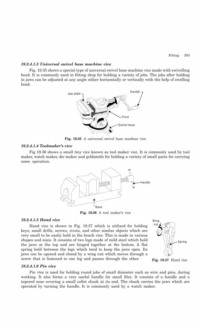
Fitting 383
19.2.4.1.3 Universal swivel base machine vice
Fig. 19.35 shows a special type of universal swivel base machine vice made with swivellinghead. It is commonly used in fitting shop for holding a variety of jobs. The jobs after holdingin jaws can be adjusted at any angle either horizontally or vertically with the help of swellinghead.
Hand leJaw pla te
P ivo t
Sw ive l base
Fig. 19.35 A universal swivel base machine vice
19.2.4.1.4 Toolmaker’s vice
Fig 19.36 shows a small tiny vice known as tool maker vice. It is commonly used by toolmaker, watch maker, die maker and goldsmith for holding a variety of small parts for carryingsome operation.
Hand le
Base
Fig. 19.36 A tool maker’s vice
19.2.4.1.5 Hand vice
Hand vice is shown in Fig. 19.37 which is utilized for holdingkeys, small drills, screws, rivets, and other similar objects which arevery small to be easily held in the bench vice. This is made in variousshapes and sizes. It consists of two legs made of mild steel which holdthe jaws at the top and are hinged together at the bottom. A flatspring held between the legs which tend to keep the jaws open. Itsjaws can be opened and closed by a wing nut which moves through ascrew that is fastened to one leg and passes through the other.
19.2.4.1.6 Pin vice
Pin vice is used for holding round jobs of small diameter such as wire and pins, duringworking. It also forms a very useful handle for small files. It consists of a handle and atapered nose covering a small collet chuck at its end. The chuck carries the jaws which areoperated by turning the handle. It is commonly used by a watch maker.
W ingnut
Spring
Fig. 19.37 Hand vice

384 Introduction to Basic Manufacturing Processes and Workshop Technology
19.2.4.2 Clamping Divices
There are two types of clamps namely C clamp and tool maker clamp. A C-clamp isshown in Fig. 19.38 which is used for gripping the work during construction or assemblywork. Whereas tool maker clamp (Fig. 19.39) is used for gripping or holding smaller jobs.
Jaw
Screw
G ripp ing ends
Screw
Fig. 19.38 C-clamp Fig. 19.39 A tool maker clamp
19.2.5 Cutting ToolsThe important common cutting tools are discussed below
19.2.5.1 Files
The widely used hand cutting tool in workshops is the file. It is a hardened piece of highgrade steel with slanting rows of teeth. It is used to cut, smooth, or fit metal parts. It is usedfile or cut softer metals. It consists of the following parts as shown in Fig. 19.40. The tangis the pointed part, which fitted into the handle. The point is the end opposite the tang. Theheel is next to the handle. The safe edge or side of a file is that which has no teeth. It isclassified on bases of type or cut of teeth and sectional form.
Tang
EdgeCuttingpoin ts
Hand leHeel
Face
Length
Fig. 19.40 Parts of a file
19.2.5.1.1 Size of a File
Size of a file is specified by its length. It is the distance from the point to the heel,without the tang. Files for fine work are usually from 100 to 200 mm and those for heavierwork from 200 to 450 mm in length.
19.2.5.1.2 Classification of Files
The files are classified on basis of type of cuts, grade and shapes. These are further subclassified as under
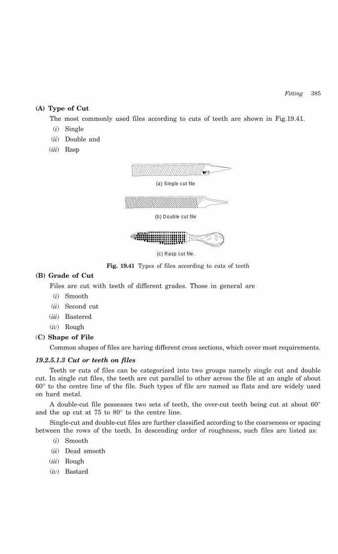
Fitting 385
(A) Type of Cut
The most commonly used files according to cuts of teeth are shown in Fig.19.41.
(i) Single
(ii) Double and
(iii) Rasp
(a ) S ing le cut file
(b ) Doub le cut file
(c) Rasp cut file.
60°
Fig. 19.41 Types of files according to cuts of teeth
(B) Grade of Cut
Files are cut with teeth of different grades. Those in general are
(i) Smooth
(ii) Second cut
(iii) Bastered
(iv) Rough
(C) Shape of File
Common shapes of files are having different cross sections, which cover most requirements.
19.2.5.1.3 Cut or teeth on files
Teeth or cuts of files can be categorized into two groups namely single cut and doublecut. In single cut files, the teeth are cut parallel to other across the file at an angle of about60° to the centre line of the file. Such types of file are named as flats and are widely usedon hard metal.
A double-cut file possesses two sets of teeth, the over-cut teeth being cut at about 60°and the up cut at 75 to 80° to the centre line.
Single-cut and double-cut files are further classified according to the coarseness or spacingbetween the rows of the teeth. In descending order of roughness, such files are listed as:
(i) Smooth
(ii) Dead smooth
(iii) Rough
(iv) Bastard

386 Introduction to Basic Manufacturing Processes and Workshop Technology
(v) Second cut
(vi) Super smooth
These files are used for finishing general surface work. Both faces of file are double cutand both edges are single cut. Such files are commonly tapered in width and thickness.
General classification of files based on shapes or cross sections are shown in Fig. 19.42along with their uses are as under:
19.2.5.1.4 Hand files
Hand files are commonly used for finishing surface work. Both faces of the file are doublecut. Either both edges are single cut or one is uncut to provide a safe edge.
19.2.5.1.5 Flat files
Flat files are generally used for filing flat surfaces in fitting shop.
19.2.5.1.6 Triangular files
Triangular files are commonly used for filing corners between 60° and 90°. They aredouble cut on all faces.
19.2.5.1.7 Square files
Square files are commonly used for filing in corners in jobs. They are double cut on allsides and tapers.
19.2.5.1.8 Round files
Round files are generally used for opening out holes and rounding inside corners. Rough,bastard, second cut and smooth files under 15 cm in length are single cut.
19.2.5.1.9 Half round files
These files comprises of flat and half round sides. The flat side of half round file is usedfor general work and the half round side for filing concave surfaces. These files are doublecut on the flat side. The curved side is single cut, smooth or second cut.
19.2.5.1.10 Knife-edge files
These files are commonly used for cleaning out acute-angled corners. The two faces ofthese files are double cut, while the edge is single cut. These files are made in sizes from10 to 20 cm of various shapes and cuts. They are extremely delicate and are used for finework such as pierced designed in thin metal.
19.2.5.1.11 Pillar files
These files are used for finishing narrow slots. Both faces are double cut and either bothedges are single cut or one is uncut to provide a safe edge of the file.
19.2.5.1.12 Needle files
Needle files are generally used for filling keys tooth wheels of clocks and other curvedsurfaces.
19.2.5.1.13 Mill files
Mill files are commonly used for filing half round recess and gullet of mill saw.
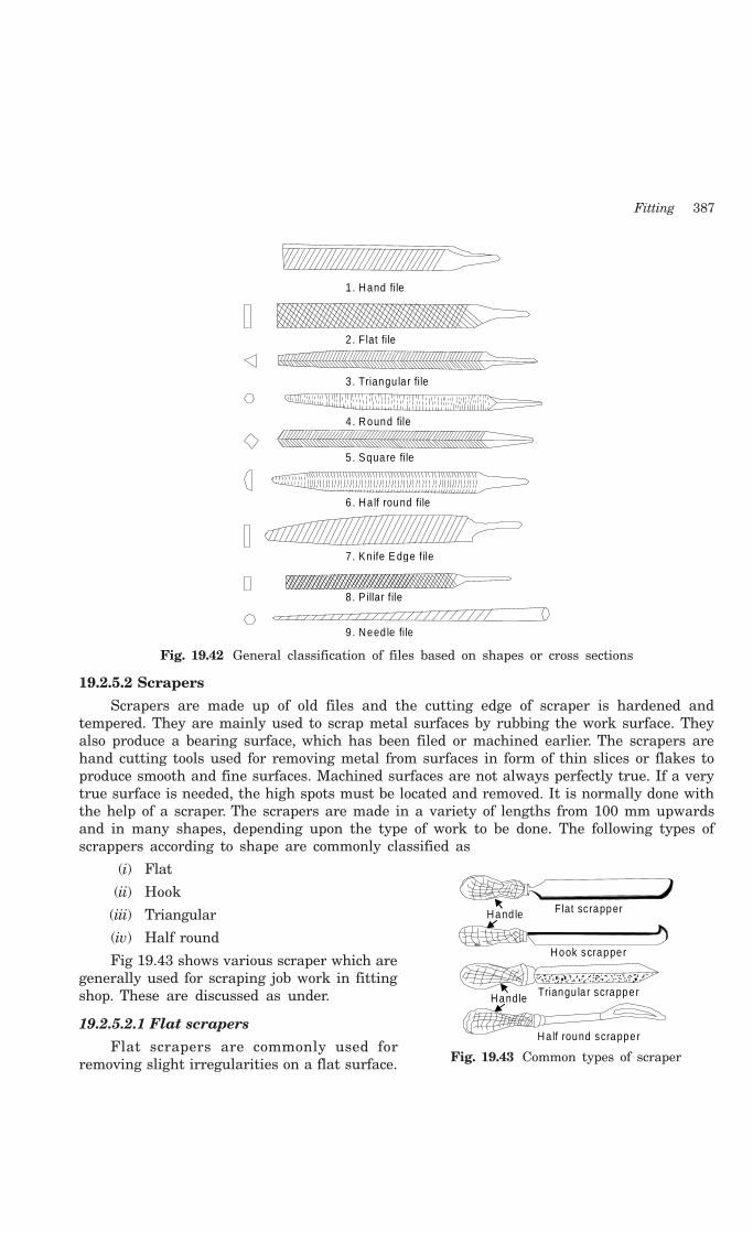
Fitting 387
1. Hand file
2 . Flat file
3 . Triangu la r file
4 . Round file
5 . Square file
6 . Ha lf round file
7 . Kn ife E dge file
8 . P illar f ile
9 . Need le file
Fig. 19.42 General classification of files based on shapes or cross sections
19.2.5.2 Scrapers
Scrapers are made up of old files and the cutting edge of scraper is hardened andtempered. They are mainly used to scrap metal surfaces by rubbing the work surface. Theyalso produce a bearing surface, which has been filed or machined earlier. The scrapers arehand cutting tools used for removing metal from surfaces in form of thin slices or flakes toproduce smooth and fine surfaces. Machined surfaces are not always perfectly true. If a verytrue surface is needed, the high spots must be located and removed. It is normally done withthe help of a scraper. The scrapers are made in a variety of lengths from 100 mm upwardsand in many shapes, depending upon the type of work to be done. The following types ofscrappers according to shape are commonly classified as
(i) Flat
(ii) Hook
(iii) Triangular
(iv) Half round
Fig 19.43 shows various scraper which aregenerally used for scraping job work in fittingshop. These are discussed as under.
19.2.5.2.1 Flat scrapers
Flat scrapers are commonly used forremoving slight irregularities on a flat surface.
Flat scrapperHand le
Hook scrapper
Triangu la r scrapper
Ha lf round scrapper
Hand le
Fig. 19.43 Common types of scraper

388 Introduction to Basic Manufacturing Processes and Workshop Technology
When the surface has been scraped with strokes in one direction, it must then be scrapedwith strokes at 90° to the first ones.
19.2.5.2.2 Hook scrapers
Hook scrapers are widely used for scraping minor job work in fitting shop.
19.2.5.2.3 Triangular scrapers
These are generally used to finish bearings in the same way as the half round scrapers, butsince they come to a sharp point at the tip they removes burrs at the edge of small holes whicha half round scraper could not enter. The faces of the scraper are hollow ground to give the toolthree cutting edges which are simpler to sharpen than the edges of the half round scraper.
19.2.5.2.4 Half-round scrapers
These types of scrapers are widely used for scraping internal cylindrical surfaces. Theyare used to remove high spots in bore & and bearings to give the right type of fit to themating shaft or journal.
Scrapers are stored carefully for protection of cutting edges from damage.
19.2.5.3 Chisel
Chisel is one of the most important tools of the sheet metal, fitting and forging shop. Itis widely used for cutting and chipping the work piece. It is made of high carbon steel or toolsteel. It is in the form of a rod having cutting edge at one end, hexagonal or octagonal bodyand striking head at the other end. The size of a chisel is described by its length and widthof edge. When the cutting edge becomes blunt, it is again sharpened by grinding. For cuttingthe job or work piece with the chisel, it is placed vertically on the job or work piece andhammering is carried out upon its head. But for chipping, the chisel is inclined at 40°-70° withthe job orwork piece. The angle of the cutting edge of the chisel is 35°-70°according to themetals to be cut.
19.2.5.4 Drill
Drill is a common tool widely formaking holes in a metal piece in fittingshop. It is generally held in chuck ofbench drilling machine shown in Fig.19.44. It usually consists of two cuttingedges set at an angle with the axis.There are three types of drills: (a) flatdrill, (b) straight fluted drill and (c) twistdrill. For fast and accurate drilling worktwist drills are commonly used. Ageneral twist drill comprises the cuttingangle of 118° and to obtain the correctdiameter of the hole. It should beground with both lips at 59° to the axisof the drill, with equal lengths of thecutting edges. The various hand drillsand their operations are shown inFig. 19.45.
Belt housing
Controls
M otor housing
O pera ting lever
Lockinghandle
Drill chuck
Transparentguard
Base
The B ench D rill
Tab le
Fig. 19.44 A bench drilling machine

Fitting 389
Breast drill
E lectric drill
Pneum atic dr ill
Hand d rill
D rill chuck
Drill Job
Fig. 19.45 Types of hand drilling machine
19.2.5.5 Reamer
The drill does not always produce the correct hole some time with good finish. Thus acorrect hole is produced with good finish of a pre drilled hole using a reamer. A common handreamer is shown in Fig. 19.46. It is commonly employed to remove minimum amount ofmetal (100 to 150 micron for rough reaming and 5 to 20 micron for fine reaming) from thehole. During reaming operations, the job should be properly supported and rigidly held. Astock wrench of appropriate size for holding the reamer is used. The reamer must be keptin its correct position relative to the job. It must be run slowly and excessive feed must beavoided. It should be always be turned in the cutting direction. Sufficient amount of cuttingfluid should also be employed. When removing the reamer, it must be turned in the cuttingdirection. Reamers with blunt or chipped edges must not be used.
Hand Ream er
Taper on end ofhand reamer
Fig. 19.46 A common hand reamer
390 Introduction to Basic Manufacturing Processes and Workshop Technology
19.2.5.5.1 Types of reamers
The reamers are classified as under.
(i) Hand reamer
(ii) Machine reamers
(iii) Parallel reamer
(iv) Taper reamer
(v) Reamers with straight flutes
(vi) Reamers with spiral flutes
(vii) Adjustable reamer
(viii) Expanding reamer
Some common types of reamer generally used in fitting shops are discussed as under.
19.2.5.5.1.1 Hand reamer
Hand reamer is operated or rotated by hand to finish holes and remove its ovality. Itscutting edges are backed off in the same manner as those of twist drills to give suitableclearance. It is made up of carbon or high speed steel. It is used for very fine internal turningin the hole by placing a tap wrench on the squared end of the reamer.
19.2.5.5.1.2 Machine reamer
Machine reamer is designed for slow speeds for use on drill presses, lathes, verticalmilling machines etc. It is chamfered on the front side of cutting edge. It possesses straightor tapered shanks and comprises of either straight or spiral flutes.
19.2.5.5.1.3 Taper reamer
Taper reamer is widely used for finishing taper holes smoothly and accurately. It is alsoused to provide a taper to a drilled hole when a taper pin is to be used. It is generallyperformed with either straight or spiral flutes. It has spaces ground into the cutting edgesor teeth to prevent overloading the entire length of each tooth of the reamer. These spacesare staggered on the various teeth to help in stock removal. The spiral fluted reamer has ashearing action that eliminates chatter and is generally preferred. Large size taper reamersare made in both roughing and finishing types. When a large amount of stock is to beremoved, a roughing reamer is generally used. The finishing reamer is commonly employedto control size and smooth the hole.
19.2.5.5.1.4 Spiral fluted reamer
Spiral fluted reamer performs greater shearing action than one with straight flute.
19.2.5.6 TAPS
Taps are used for cutting or producing internal threads of either left or right hand kindin nuts or pre-drilled holes. Taps are threaded externally. The threads being cut by grindingto give a high class finish. Taps are made up of alloy steel or hardened steel. To providecutting edges, grooves known as flutes are ground along the threaded portion of the tap sothat the thread is divided into rows of teeth. The number of flutes on tap varies from twoto eight whereas four being the most common. The flutes acts as channels to carry away thechips formed during tapping or cutting threads. The nomenclature of a typical tap is shown

Fitting 391
in Fig. 19.47. Taps are may be of many types such as hand taps, machine taps, pipe taps, solidtaps, straight and bend shank taps. Hand taps are usually made in sets of three: (1) taper tap(2) plug tap (3) bottoming tap as shown in Fig. 19.48. The taper tap is tapered off for 8 or 10threads, and is used first, cutting to the full thread gradually. The intermediate tap usuallyhas two or three threads chamfered. The second tap can finish a through hole. The plug taphas a full-sized un-tapered thread to the end and is the main finishing tap. In the case of blindhole, a plug tap must be used.
Thread re lie f(Radial)
Length o f shank Length o f bodyCham fer
Cutting face
Flute
Heel
Land
O vera ll leng th
Length o f Sq
Sha
nk
Dia
Poi
nt
Dia
Fig. 19.47 Nomenclature of tap
Taper tap
Plug tap
Bottom ing tap
Fig. 19.48 Types of hand taps
19.2.5.7 Hand snip or shear
Various kinds of snips or shears are described in chapter pertaining to sheet metal work.They are commonly employed for cutting or shearing metal sheets to required shapes andsizes. Few snips are available for making straight or circular cuts. The most common typesof snips in use are:
(a) Straight snips,
(b) Bent snips and
(c) Slitting shears
19.2.5.8 Hand hacksaw
Hand hacksaws are made in two types namely a fixed frame and adjustable frame orientedas shown in Fig.19.49 and Fig.19.50. The former possesses solid frame in which the lengthcannot be changed and where as the latter comprises the adjustable frame which has a backthat can be lengthened or shortened to hold blades of different sizes. The hand hacksaws arecommonly used for sawing all soft metal. They consist of a frame, handle, prongs, tighteningscrew and nut, and blade as shown in figure. Its frame is made to hold the blade tightly. Howevera power operated hacksaw can also be used for cutting raw materials in sizes in case ofcontinuous cutting generally occurring frequently in fitting or in machine shops.
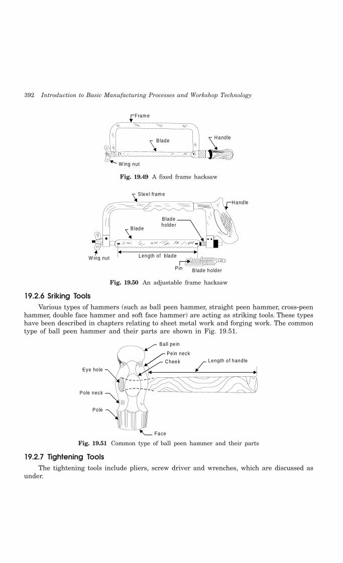
392 Introduction to Basic Manufacturing Processes and Workshop Technology
Fram e
Hand leBlade
W ing nut
Fig. 19.49 A fixed frame hacksaw
Stee l fram e
Hand le
B lade ho lder
Length o f bladeW ing nut
B lade
Bladeholder
P in
Fig. 19.50 An adjustable frame hacksaw
19.2.6 Sriking ToolsVarious types of hammers (such as ball peen hammer, straight peen hammer, cross-peen
hammer, double face hammer and soft face hammer) are acting as striking tools. These typeshave been described in chapters relating to sheet metal work and forging work. The commontype of ball peen hammer and their parts are shown in Fig. 19.51.
Ball pe in
Pe in neck
Cheek Length o f handle
Eye ho le
Po le neck
Po le
Face
Fig. 19.51 Common type of ball peen hammer and their parts
19.2.7 Tightening ToolsThe tightening tools include pliers, screw driver and wrenches, which are discussed as
under.

Fitting 393
19.2.7.1 Pliers
Pliers are namely ordinary needle nose and special type. Fig 19.52(a) shows a long nosepliers and Fig. 19.52(b) shows a combination pliers. These are commonly used by fitter andelectrician for holding a variety of jobs.
(a ) Long nose p lie rs. (b ) Combination p liers.
Fig. 19.52 Long nose pliers and combination pliers
19.2.7.2 Screw driver
Screw driver is a screw tightening tool. The most commonly used standard screw driverwith its parts is shown in Fig 19.53. It is generally used by hand for tightening the screws.It is also of various types depending upon the kind of work.
Hand leFerru le
Shank Blade
Po in t
Length o f shankLength o f hand le
Fig. 19.53 Standard screw driver with its parts
19.2.7.3 Wrenches
Wrenches are commonly known as spanners. These generally come in sets and arecommonly identified by numbers. These are of various types and few general types involveopen single ended, open double ended, closed ended adjustable, ring spanner, offset socket,t-socket, box wrench, pipe wrench and Allen wrench.
19.3 OPERATIONS PERFORMED IN FITTING WORK
The operations commonly performed in bench and fitting work may be classified asunder.
1. Marking 2. Chipping
3. Filing 4. Scrapping
5. Sawing 6. Drilling
7. Reaming 8. Tapping
9. Grinding and 10. Polishing
Some common operations are discussed as under.
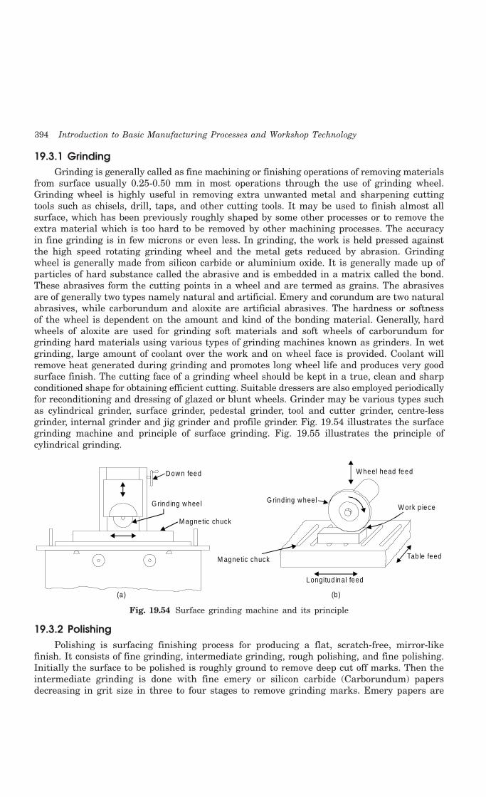
394 Introduction to Basic Manufacturing Processes and Workshop Technology
19.3.1 GrindingGrinding is generally called as fine machining or finishing operations of removing materials
from surface usually 0.25-0.50 mm in most operations through the use of grinding wheel.Grinding wheel is highly useful in removing extra unwanted metal and sharpening cuttingtools such as chisels, drill, taps, and other cutting tools. It may be used to finish almost allsurface, which has been previously roughly shaped by some other processes or to remove theextra material which is too hard to be removed by other machining processes. The accuracyin fine grinding is in few microns or even less. In grinding, the work is held pressed againstthe high speed rotating grinding wheel and the metal gets reduced by abrasion. Grindingwheel is generally made from silicon carbide or aluminium oxide. It is generally made up ofparticles of hard substance called the abrasive and is embedded in a matrix called the bond.These abrasives form the cutting points in a wheel and are termed as grains. The abrasivesare of generally two types namely natural and artificial. Emery and corundum are two naturalabrasives, while carborundum and aloxite are artificial abrasives. The hardness or softnessof the wheel is dependent on the amount and kind of the bonding material. Generally, hardwheels of aloxite are used for grinding soft materials and soft wheels of carborundum forgrinding hard materials using various types of grinding machines known as grinders. In wetgrinding, large amount of coolant over the work and on wheel face is provided. Coolant willremove heat generated during grinding and promotes long wheel life and produces very goodsurface finish. The cutting face of a grinding wheel should be kept in a true, clean and sharpconditioned shape for obtaining efficient cutting. Suitable dressers are also employed periodicallyfor reconditioning and dressing of glazed or blunt wheels. Grinder may be various types suchas cylindrical grinder, surface grinder, pedestal grinder, tool and cutter grinder, centre-lessgrinder, internal grinder and jig grinder and profile grinder. Fig. 19.54 illustrates the surfacegrinding machine and principle of surface grinding. Fig. 19.55 illustrates the principle ofcylindrical grinding.
Down feed
G rind ing whee l
M agnetic chuck
(a)
W heel head feed
G rind ing whee lW ork p iece
Tab le feed
Longitud inal feed
(b)
M agnetic chuck
Fig. 19.54 Surface grinding machine and its principle
19.3.2 PolishingPolishing is surfacing finishing process for producing a flat, scratch-free, mirror-like
finish. It consists of fine grinding, intermediate grinding, rough polishing, and fine polishing.Initially the surface to be polished is roughly ground to remove deep cut off marks. Then theintermediate grinding is done with fine emery or silicon carbide (Carborundum) papersdecreasing in grit size in three to four stages to remove grinding marks. Emery papers are

Fitting 395
graded from fine to coarse. This polishing operation may be performed by hand or mechanicallyusing the rotating disks. The motion in polishing of work on polishing wheel should alwaysbe straight and the polishing strokes should cover the whole length of the surface beingpolished. Finer grade emery disc pr polishing wheel should be used for the fine finish work.Polishing is commonly performed on utensils.
G rind ing wheel
Tails tockCylindricalJob
Headstock
DogDrive p la te
Upper table
Lower table
Fig. 19.55 Principle of cylindrical grinding
19.3.3 Surface CoatingThe various manufacturing processes such as casting, forging, machining, hot working,
cold working and joining processes etc. produce different surfaces. Therefore for gettingdesired surface of the part, subsequent surface preservation processes are needed. Thesepreservation processes are called as surface coating of metals. Coatings on surfaces areemployed on most metal parts, either for protective or for decorative or for both purposes.The main objectives of coatings involve for the purpose of decoration, surface protection,corrosion resistance and providing of a hard surface. The surface covering with coating mustbe uniform and free from runs, checks or peelings. Coatings are commonly applied to thefinished components to form the final product. For successful coating, clean and smoothsurface finishes is required for assuring good adhesion during coating. Cleaning operationsare performed both preparatory to finishing operations and after finishing operations. Theyare primarily used to remove dirt, oil, oxides, scale, and other harmful ingredients thatultimately affect the life of the product. There are various methods of cleaning, drying, andcompetitive means of applying the coating. However, the various processes involved in preparingwork for coating and applying the coatings are closely interrelated. Galvanizing, parkerizing,electroplating and painting are the common surface coating processes employed for protectingthe surfaces of the work pieces.
19.4 QUESTIONS1. How will you classify the tools commonly used in fitting ?
2. Explain briefly the various clamping tools used in fitting shop using neat sketches.
3. Explain in brief with neat sketches the various types of measuring tools used in fitting shop.
4. Explain the construction and working of vernier caliper using neat sketch. How its least countcan be determined? What are its uses?
396 Introduction to Basic Manufacturing Processes and Workshop Technology
5. Explain the construction and working of micrometer with neat sketches. How its least countcan be determined?
6. Explain in brief the various types of cutting tools used in fitting shop using neat sketches.
7. Explain in brief the various precautions associated with hand hacksaw, files and chisels.
8. Explain in brief the various types of striking tools used in fitting shop using neat sketches.
9. Explain the various types of files used in fitting shop. How are they classified ?
10. Explain the following tools.
(i) Drill (ii) Reamer
(iii) Taps (iv) Die and die stock
11. Write short notes on the following operations:
(i) Marking (ii) Filing (iii) Chipping
(iv) Sawing (v) Drilling (vi) Tapping
(vii) Grinding (viii) Polishing (ix) Punching
12. What is the main difference between the hand hammers used in a smithy shop and a fittingshop?
13. What is the difference between hand hacksaw used in fitting shop and the saws used incarpentry shop?
14. Write short notes on the following:
(i) Polishing (ii) Buffing (iii) Boring
(iv) Milling (v) Broaching (vi) Shaping
(vii) Grinding.
15. How will you achieve the following?
(i) Rate of production (ii) Accuracy and
(iii) Surface finish

397
METAL CUTTING
20.1 INTRODUCTION
Metal cutting or traditional machining processes are also known as conventional machiningprocesses. These processes are commonly carried out in machine shops or tool room formachining a cylindrical or flat jobs to a desired shape, size and finish on a rough block of jobmaterial with the help of a wedge shaped tool. The cutting tool is constrained to move relativeto the job in such a way that a layer of metal is removed in the form of a chip. General metalcutting operations are shown in Fig. 20.1. These machining processes are performed on metalcutting machines, more commonly termed as machine tools using various types of cuttingtools (single or multi-point). A machine tool is a power driven metal cutting machine whichassist in managing the needed relative motion between cutting tool and the job that changesthe size and shape of the job material. In metal cutting (machining) process, working motionis imparted to the workpiece and cutting tool by the mechanisms of machine tool so that thework and tool travel relative to each other and machine the workpiece material in the formof shavings (or swarf) known as chips.
M ach ined work jobToo l
Ch ip
M otion o f work job
Cutting edge a t 90 to the d irection o f jobtool m otion
Cutting edge inc lined in p lane v iew
(a) O rthogona l cutting (b ) O blique cutting
Ch ip
Too l
M otion o f work job
M ach ined work job
Fig. 20.1 Metal cutting operation
20CHAPTER
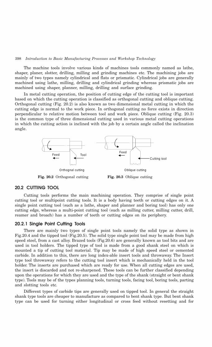
398 Introduction to Basic Manufacturing Processes and Workshop Technology
The machine tools involve various kinds of machines tools commonly named as lathe,shaper, planer, slotter, drilling, milling and grinding machines etc. The machining jobs aremainly of two types namely cylindrical and flats or prismatic. Cylindrical jobs are generallymachined using lathe, milling, drilling and cylindrical grinding whereas prismatic jobs aremachined using shaper, planner, milling, drilling and surface grinding.
In metal cutting operation, the position of cutting edge of the cutting tool is importantbased on which the cutting operation is classified as orthogonal cutting and oblique cutting.Orthogonal cutting (Fig. 20.2) is also known as two dimensional metal cutting in which thecutting edge is normal to the work piece. In orthogonal cutting no force exists in directionperpendicular to relative motion between tool and work piece. Oblique cutting (Fig. 20.3)is the common type of three dimensional cutting used in various metal cutting operationsin which the cutting action is inclined with the job by a certain angle called the inclinationangle.
Feed Too l
O rthogna l cu tting
Feed
O blique cutting
Cutting tool
Fig. 20.2 Orthogonal cutting Fig. 20.3 Oblique cutting
20.2 CUTTING TOOL
Cutting tools performs the main machining operation. They comprise of single pointcutting tool or multipoint cutting tools. It is a body having teeth or cutting edges on it. Asingle point cutting tool (such as a lathe, shaper and planner and boring tool) has only onecutting edge, whereas a multi-point cutting tool (such as milling cutter, milling cutter, drill,reamer and broach) has a number of teeth or cutting edges on its periphery.
20.2.1 Single Point Cutting ToolsThere are mainly two types of single point tools namely the solid type as shown in
Fig.20.4 and the tipped tool (Fig.20.5). The solid type single point tool may be made from highspeed steel, from a cast alloy. Brazed tools (Fig.20.6) are generally known as tool bits and areused in tool holders. The tipped type of tool is made from a good shank steel on which ismounted a tip of cutting tool material. Tip may be made of high speed steel or cementedcarbide. In addition to this, there are long index-able insert tools and throwaway. The Inserttype tool throwaway refers to the cutting tool insert which is mechanically held in the toolholder. The inserts are purchased which are ready for use. When all cutting edges are used,the insert is discarded and not re-sharpened. These tools can be further classified dependingupon the operations for which they are used and the type of the shank (straight or bent shanktype). Tools may be of the types planning tools, turning tools, facing tool, boring tools, partingand slotting tools etc.
Different types of carbide tips are generally used on tipped tool. In general the straightshank type tools are cheaper to manufacture as compared to bent shank type. But bent shanktype can be used for turning either longitudinal or cross feed without resetting and for
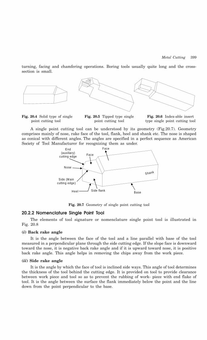
Metal Cutting 399
turning, facing and chamfering operations. Boring tools usually quite long and the cross-section is small.
Fig. 20.4 Solid type of single Fig. 20.5 Tipped type single Fig. 20.6 Index-able insert point cutting tool point cutting tool type single point cutting tool
A single point cutting tool can be understood by its geometry (Fig.20.7). Geometrycomprises mainly of nose, rake face of the tool, flank, heel and shank etc. The nose is shapedas conical with different angles. The angles are specified in a perfect sequence as AmericanSociety of Tool Manufacturer for recognizing them as under.
Face
Nose
End (auxilia ry)
cutting edge
Side (M ain cutting edge)
S ide flank Base
Shank
Face
Heel
Fig. 20.7 Geometry of single point cutting tool
20.2.2 Nomenclature Single Point ToolThe elements of tool signature or nomenclature single point tool is illustrated in
Fig. 20.8
(i) Back rake angle
It is the angle between the face of the tool and a line parallel with base of the toolmeasured in a perpendicular plane through the side cutting edge. If the slope face is downwardtoward the nose, it is negative back rake angle and if it is upward toward nose, it is positiveback rake angle. This angle helps in removing the chips away from the work piece.
(ii) Side rake angle
It is the angle by which the face of tool is inclined side ways. This angle of tool determinesthe thickness of the tool behind the cutting edge. It is provided on tool to provide clearancebetween work piece and tool so as to prevent the rubbing of work- piece with end flake oftool. It is the angle between the surface the flank immediately below the point and the linedown from the point perpendicular to the base.
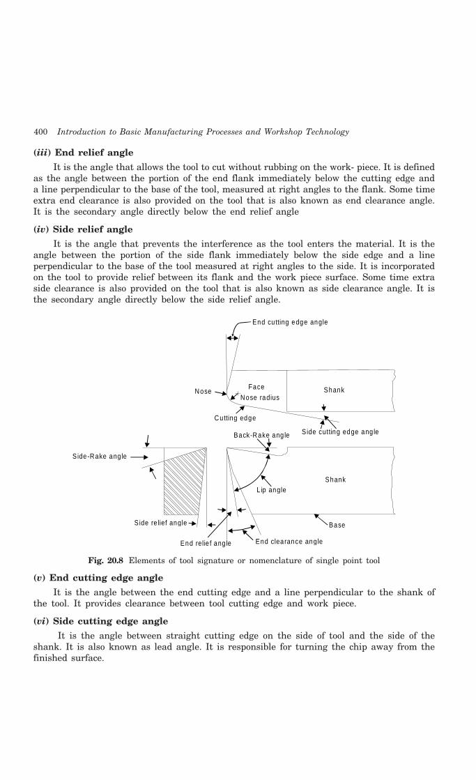
400 Introduction to Basic Manufacturing Processes and Workshop Technology
(iii) End relief angle
It is the angle that allows the tool to cut without rubbing on the work- piece. It is definedas the angle between the portion of the end flank immediately below the cutting edge anda line perpendicular to the base of the tool, measured at right angles to the flank. Some timeextra end clearance is also provided on the tool that is also known as end clearance angle.It is the secondary angle directly below the end relief angle
(iv) Side relief angle
It is the angle that prevents the interference as the tool enters the material. It is theangle between the portion of the side flank immediately below the side edge and a lineperpendicular to the base of the tool measured at right angles to the side. It is incorporatedon the tool to provide relief between its flank and the work piece surface. Some time extraside clearance is also provided on the tool that is also known as side clearance angle. It isthe secondary angle directly below the side relief angle.
End clearance angleEnd relie f ang le
S ide re lief angle
L ip angle Shank
Side cutting edge ang le
Base
Back-Rake ang le
S ide-Rake ang le
Cutting edge
Nose radius
Face
End cu tting edge angle
ShankNose
Fig. 20.8 Elements of tool signature or nomenclature of single point tool
(v) End cutting edge angle
It is the angle between the end cutting edge and a line perpendicular to the shank ofthe tool. It provides clearance between tool cutting edge and work piece.
(vi) Side cutting edge angle
It is the angle between straight cutting edge on the side of tool and the side of theshank. It is also known as lead angle. It is responsible for turning the chip away from thefinished surface.

Metal Cutting 401
(vii) Nose radius
It is the nose point connecting the side cutting edge and end cutting edge. It possessessmall radius which is responsible for generating surface finish on the work-piece
20.2.3 Tool SignatureConvenient way to specify tool angles by use of a standardized abbreviated system is
known as tool signature or tool nomenclature. It indicates the angles that a tool utilizesduring the cut. It specifies the active angles of the tool normal to the cutting edge. This willalways be true as long as the tool shank is mounted at right angles to the work-piece axis.The seven elements that comprise the signature of a single point cutting tool can be statedin the following order:
Tool signature 0-7-6-8-15-16-0.8
1. Back rake angle (0°)
2. Side rake angle (7°)
3. End relief angle (6°)
4. Side relief angle (8°)
5. End cutting edge angle (15°)
6. Side cutting edge angle (16°)
7. Nose radius (0.8 mm)
20.3 MECHANICS OF METAL CUTTING
Metal cutting operation is illustrated in Fig. 20.9. The work piece is securely clampedin a machine tool vice or clamps or chuck or collet. A wedge shape tool is set to a certaindepth of cut and is forced to move in direction as shown in figure. All traditional machiningprocesses require a cutting tool having a basic wedge shape at the cutting edge. The tool willcut or shear off the metal, provided (i) the tool is harder than the metal, (ii) the tool isproperly shaped so that its edge can be effective in cutting the metal, (iii) the tool is strongenough to resist cutting pressures but keen enough to sever the metal, and (iv) providedthere is movement of tool relative to the material or vice versa, so as to make cutting actionpossible. Most metal cutting is done by high speed steel tools or carbide tools. In metalcutting, the tool does not slide through metal as a jack knife does through wood, not doesthe tool split the metal as an axe does a log. Actually, the metal is forced off the workpieceby being compressed, shearing off, and sliding along the face of the cutting tool. The way acutting tool cuts the metal can be explained as follows. All metals in the solid state have acharacteristic crystalline structure, frequently referred to as grain structure. The grain orcrystals vary in size from very fine to very coarse, depending upon the type of metal and itsheat-treatment. The cutting tool advances again in the work piece. Heavy forces are exertedon the crystals in front of the tool face. These crystals, in turn exert similar pressures oncrystals ahead of them, in the direction of the cut or force applied by the cutter. As the toolcontinues to advance, the material at sheared point is sheared by the cutting edge of the toolor it may be torn loose by the action of the bending chip which is being formed. As the tooladvances, maximum stress is exerted along sheared line, which is called the shear plane. Thisplane is approximately perpendicular to the cutting face of the tool. There exists a shear zoneon both sides of the shear plane, when the force of the tool exceeds the strength of the

402 Introduction to Basic Manufacturing Processes and Workshop Technology
material at the shear plane, rupture or slippage of the crystalline grain structure occurs, thusforming the metal chip. The chip gets separated from the workpiece material and moves upalong the tool face. In addition, when the metal is sheared, the crystals are elongated, thedirection of elongation being different from that of shear. The circles which represent thecrystals in the uncut metal get elongated into ellipses after leaving the shearing plane.
Depth o f cu t
Job p iece
Too l
ForceCh ip
(a ) (b ) (c)
Job p iece Job p iece
Too l Too l
Fig. 20.9 Metal cutting operation
20.4 TYPES OF CHIPS
In a metal cutting operation is carried out in machine shop. Chips are separated fromthe workpiece to impart the required size and shape to the workpiece. The type of chips edgeformed is basically a function of the work material and cutting conditions. The chips that areformed during metal cutting operations can be classified into four types:
1. Discontinuous or segmental chips
2. Continuous chips
3. Continuous chips with built-up edge.
4. Non homogenous chips
The above three common types of chips are shown in Fig. 20.10
Fig. 20.10 (a) shows continuous chips coming out during machining in machine shop.These types of chips are obtained while machining ductile material such as mild steel andcopper. A continuous chip comes from the cutting edge of a cutting tool as a single one piece,and it will remain as one piece unless purposely broken for safety or for convenience inhandling. Formation of very lengthy chip is hazardous to the machining process and themachine operators. It may wrap up on the cutting tool, work piece and interrupt in thecutting operation. Thus, it becomes necessary to deform or break long continuous chips intosmall pieces. It is done by using chip breakers. Chip breaker can be an integral part of thetool design or a separate device.
Fig. 20.10 (b) shows discontinuous chips coming out during machining in machine shop.In this type, the chip is produced in the form of small pieces. These types of chips are obtainedwhile machining brittle material like cast iron, brass and bronze. Fairly good surface finishis obtained and tool life is increased with this type of chips.
Fig. 20.10 (c) shows continuous chip with built-up edge. During cutting operation, thetemperature rises and as the hot chip passes over s the face of the tool, alloying and weldingaction may take place due to high pressure, which results in the formation of weak bonds inmicrostructure and weakened particles might pullout. Owing to high heat and pressuregenerated, these particles get welded to the cutting tip of the tool and form a false cuttingedge. This is known as built-up edge
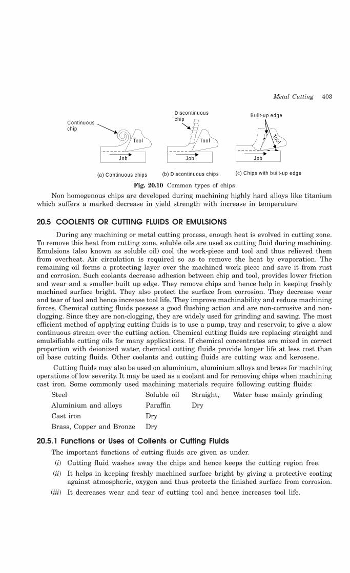
Metal Cutting 403
Continuous chip
D iscon tinuouschip
Bu ilt-up edge
Too l
Too lToo l
Job Job Job
(a) Continuous chips (b ) D iscon tinuous chips (c) Ch ips w ith built-up edge
Fig. 20.10 Common types of chips
Non homogenous chips are developed during machining highly hard alloys like titaniumwhich suffers a marked decrease in yield strength with increase in temperature
20.5 COOLENTS OR CUTTING FLUIDS OR EMULSIONS
During any machining or metal cutting process, enough heat is evolved in cutting zone.To remove this heat from cutting zone, soluble oils are used as cutting fluid during machining.Emulsions (also known as soluble oil) cool the work-piece and tool and thus relieved themfrom overheat. Air circulation is required so as to remove the heat by evaporation. Theremaining oil forms a protecting layer over the machined work piece and save it from rustand corrosion. Such coolants decrease adhesion between chip and tool, provides lower frictionand wear and a smaller built up edge. They remove chips and hence help in keeping freshlymachined surface bright. They also protect the surface from corrosion. They decrease wearand tear of tool and hence increase tool life. They improve machinability and reduce machiningforces. Chemical cutting fluids possess a good flushing action and are non-corrosive and non-clogging. Since they are non-clogging, they are widely used for grinding and sawing. The mostefficient method of applying cutting fluids is to use a pump, tray and reservoir, to give a slowcontinuous stream over the cutting action. Chemical cutting fluids are replacing straight andemulsifiable cutting oils for many applications. If chemical concentrates are mixed in correctproportion with deionized water, chemical cutting fluids provide longer life at less cost thanoil base cutting fluids. Other coolants and cutting fluids are cutting wax and kerosene.
Cutting fluids may also be used on aluminium, aluminium alloys and brass for machiningoperations of low severity. It may be used as a coolant and for removing chips when machiningcast iron. Some commonly used machining materials require following cutting fluids:
Steel Soluble oil Straight, Water base mainly grinding
Aluminium and alloys Paraffin Dry
Cast iron Dry
Brass, Copper and Bronze Dry
20.5.1 Functions or Uses of Collents or Cutting FluidsThe important functions of cutting fluids are given as under.
(i) Cutting fluid washes away the chips and hence keeps the cutting region free.
(ii) It helps in keeping freshly machined surface bright by giving a protective coatingagainst atmospheric, oxygen and thus protects the finished surface from corrosion.
(iii) It decreases wear and tear of cutting tool and hence increases tool life.
404 Introduction to Basic Manufacturing Processes and Workshop Technology
(iv) It improves machinability and reduce power requirements
(v) It prevents expansion of work pieces.
(vi) It cools the tool and work piece and remove the generated heat from the cutting zone.
(vii) It decreases adhesion between chip and tool; provide lower friction and wear, anda smaller built-up edge.
20.6 NON TRADITIONAL OR UNCONVENTIONAL MACHINING PROCESSES
Non traditional machining processes are also known as un-conventional metal machiningor advance machining processes. The recent increase in the use of hard, high strength andtemperature resistant materials in engineering has necessitated the development of newermachining techniques. With the exception of grinding, conventional methods of removingmaterial from a workpiece are not readily applicable to these new materials. New materialssuch as hastalloy, nitralloy, waspalloy, nimonics, carbides etc., are difficult to machine andwhich possess tremendous applications in aircrafts, nuclear reactors, turbines, special cuttingtools etc. Conventional machining processes when applied to these harder materials havefollowing difficulties which are given as under.
(i) Conventional machining processes are uneconomical to these material,
(ii) Produce poor degree of accuracy and surface finish,
(iii) Produce some stress in the metal being cut whereas newer machining techniquesare essentially stress free.
(iv) Theses processes are slow and highly insufficient.
Although most of the new machining processes have been developed specifically fornewer materials that are difficult to machine, some of them (processes) have found use in theproduction of complex shapes and cavities in softer, more readily machined materials.
20.6.1 CLassification of Unconventional Machining ProcessesNon-traditional or unconventional machining processes may be classified on the basis of
the nature of energy employed in machining,1. Chemical
1. Chemical machining (CHM)2. Electro-chemical
1. Electro-chemical machining (ECM)2. Electrolytic grinding (ECG)
3. Electro-thermal1. Electrical discharge machining (EDM)2. Electron beam machining (EBM)3. Plasma arc machining (PAM)4. Laser beam machining (LBM)
4. Mechanical1. Ultrasonic machining (USM)2. Abrasive jet machining (AJM)
3. Water jet machining (WJM)
Metal Cutting 405
20.7 QUESTIONS
1. Show the nomenclature of a single point cutting tool using orthographic projections.
2. Show nomenclature of the following cutting tools:
(i) Single point cutting tool
(ii) Drill
(iii) Milling cutter
3. Explain orthogonal cutting and oblique cutting
4. Explain mechanism of chip formation with neat sketches.
5. Explain various types of chips with neat sketches.
6. What are objectives of cutting fluids?
7. Explain the mechanisms of tool wear. What are its regions?
8. What are the various costs associated with machining operation.
9. For a given set of conditions, how would you arrive at the best cutting speed for maximumproduction?
10. Describe the various types of chips in metal cutting.
1. What is a chip breaker
2. Orthogonal cutting
3. Oblique cutting
4. Friction of chip and tool.
5. Heat generated and dissipated in metal cutting?
11. Describe power hacksaw with neat sketch.
12. What safety precautions are associated with operation of a power hacksaw machine?
13. Explain various safety precautions are to be considered while working in machine shop.

406 Introduction to Basic Manufacturing Processes and Workshop Technology
406
LATHE MACHINE
21.1 INTRODUNCTION
Lathe is one of the most versatile and widely used machine tools all over the world. Itis commonly known as the mother of all other machine tool. The main function of a latheis to remove metal from a job to give it the required shape and size. The job is secure1y andrigid1y held in the chuck or in between centers on the lathe machine and then turn it againsta single point cutting tool which wi1l remove meta1 from the job in the form of chips.Fig. 21.1 shows the working principle of lathe. An engine lathe is the most basic and simplestform of the lathe. It derives its name from the early lathes, which obtained their power fromengines. Besides the simple turning operation as described above, lathe can be used to carryout other operations also, such as drilling, reaming, boring, taper turning, knurling, screw-thread cutting, grinding etc.
Head stockcentre
Tail s tockcentre
W ork
Too l
Fig. 21.1 Working principal of lathe machine
21.2 TYPES OF LATHE
Lathes are manufactured in a variety of types and sizes, from very small bench lathesused for precision work to huge lathes used for turning large steel shafts. But the principleof operation and function of all types of lathes is same. The different types of lathes are:
1. Speed lathe
(a) Wood working
(b) Spinning
(c) Centering
(d) Po1ishing
21CHAPTER

Lathe Machine 407
2. Centre or engine lathe(a) Be1t drive(b) Individual motor drive(c) Gear head lathe
3. Bench lathe4. Tool room Lathe5. Capstan and Turret 1athe6. Special purpose lathe
(a) Whee1 lathe(b) Gap bed lathe(c) Dup1icating lathe(d) T-lathe
7. Automatic latheSome of common lathes are described as under.
21.2.1 Speed LatheSpeed lathe is simplest of all types of lathes in construction and operation. The important
parts of speed lathe are following-
(1) Bed
(2) Headstock
(3) Tailstock, and
(4) Tool post mounted on an adjustable slide.
It has no feed box, 1eadscrew or conventional type of carriage. The tool is mounted on theadjustable slide and is fed into the work by hand contro1. The speed lathe finds applications wherecutting force is least such as in wood working, spinning, centering, polishing, winding, buffing etc.This lathe has been so named because of the very high speed of the headstock spindle.
21.2.2 Centre Lathe or Engine LatheThe term “engine” is associated with this lathe due to the fact that in the very early days
of its development it was driven by steam engine. This lathe is the important member of thelathe family and is the most widely used. Similar to the speed lathe, the engine lathe has allthe basic parts, e.g., bed, headstock, and tailstock. But its headstock is much more robust inconstruction and contains additional mechanism for driving the lathe spindle at multiplespeeds. An engine lathe is shown in Fig. 21.2. Unlike the speed lathe, the engine lathe canfeed the cutting tool both in cross and longitudinal direction with reference to the lathe axiswith the help of a carriage, feed rod and lead screw. Centre lathes or engine lathes areclassified according to methods of transmitting power to the machine. The power may betransmitted by means of belt, electric motor or through gears.
22.2.3 Bench LatheThis is a small lathe usually mounted on a bench. It has practically all the parts of an
engine lathe or speed lathe and it performs almost all the operations. This is used for smalland precision work.

408 Introduction to Basic Manufacturing Processes and Workshop Technology
Head stock Too l postTail s tock
Bed
Carriage
Leg
Speed live r
Fig. 21.2 Principal components of a central lathe
22.2.4 Tool Room LatheThis lathe has features similar to an engine lathe but it is much more accurately built.
It has a wide range of spindle speeds ranging from a very low to a quite high speed up to2500 rpm. This lathe is mainly used for precision work on tools, dies, gauges and in machiningwork where accuracy is needed.
22.2.5 Capstan and Turret LatheThe development of these 1athes results from the technological advancement of the engine
lathe and these are vastly used for mass production work. The distinguishing feature of thistype of lathe is that the tailstock of an engine lathe is replaced by a hexagonal turret, on theface of which multiple tools may be fitted and fed into the work in proper sequence. Due to thisarrangement, several different types of operations can be done on a job without re-setting ofwork or tools, and a number of identical parts can be produced in the minimum time.
21.2.6 Special Purpose LathesThese lathes are constructed for special purposes and for jobs, which cannot be
accommodated or conveniently machined on a standard lathe. The wheel lathe is made forfinishing the journals and turning the tread on railroad car and locomotive wheels. The gapbed lathe, in which a section of the bed adjacent to the headstock is removable, is used toswing extra-large-diameter pieces. The T-lathe is used for machining of rotors for jet engines.The bed of this lathe has T-shape. Duplicating lathe is one for duplicating the shape of a flator round template on to the job.
21.2.7 Automatic LathesThese lathes are so designed that all the working and job handling movements of the
complete manufacturing process for a job are done automatically. These are high speed, heavyduty, mass production lathes with complete automatic control.
21.3 CONSTRUCTION OF LATHE MACHINE
A simple lathe comprises of a bed made of grey cast iron on which headstock, tailstock,carriage and other components of lathe are mounted. Fig. 21.3 shows the different parts ofengine lathe or central lathe. The major parts of lathe machine are given as under:

Lathe Machine 409
1. Bed
2. Head stock
3. Tailstock
4. Carriage
5. Feed mechanism
6. Thread cutting mechanism
M andrel gear Head stockSp indle Too l
post
Compound rest Dead
centre
Sp indle lock
Tail s tockTail s tock lock
Feed reverse Hand cross feed
Rack Lead screw
Feed engage lever
Feed sha ft
Screw cutting engage lever
Reverse for slid ing and surfac ing
Hand traverse
O il sum p L ive cen tre
Storage fo r gearschucks
tools e tc.
G uard
Fig. 21.3 Different parts of engine lathe or central lathe
21.3.1 BedThe bed of a lathe machine is the base on which all other parts of lathe are mounted.
It is massive and rigid single piece casting made to support other active parts of lathe. Onleft end of the bed, headstock of lathe machine is located while on right side tailstock islocated. The carriage of the machine rests over the bed and slides on it. On the top of thebed there are two sets of guideways-innerways and outerways. The innerways provide slidingsurfaces for the tailstock and the outerways for the carriage. The guideways of the lathe bedmay be flat and inverted V shape. Generally cast iron alloyed with nickel and chromiummaterial is used for manufacturing of the lathe bed.
21.3.2 Head StockThe main function of headstock is to transmit power to the different parts of a lathe. It
comprises of the headstock casting to accommodate all the parts within it including gear trainarrangement. The main spindle is adjusted in it, which possesses live centre to which thework can be attached. It supports the work and revolves with the work, fitted into the mainspindle of the headstock. The cone pulley is also attached with this arrangement, which isused to get various spindle speed through electric motor. The back gear arrangement is used
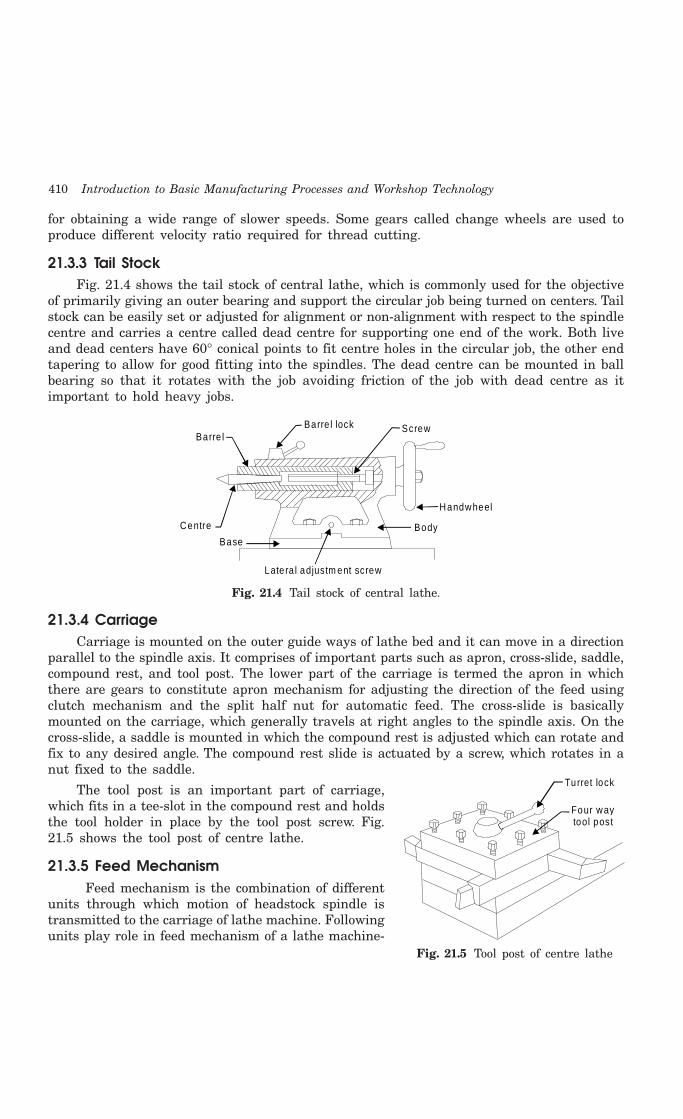
410 Introduction to Basic Manufacturing Processes and Workshop Technology
for obtaining a wide range of slower speeds. Some gears called change wheels are used toproduce different velocity ratio required for thread cutting.
21.3.3 Tail StockFig. 21.4 shows the tail stock of central lathe, which is commonly used for the objective
of primarily giving an outer bearing and support the circular job being turned on centers. Tailstock can be easily set or adjusted for alignment or non-alignment with respect to the spindlecentre and carries a centre called dead centre for supporting one end of the work. Both liveand dead centers have 60° conical points to fit centre holes in the circular job, the other endtapering to allow for good fitting into the spindles. The dead centre can be mounted in ballbearing so that it rotates with the job avoiding friction of the job with dead centre as itimportant to hold heavy jobs.
Barre l lockBarre l
Screw
Centre
Handwheel
BodyBase
Latera l adjustm ent screw
Fig. 21.4 Tail stock of central lathe.
21.3.4 CarriageCarriage is mounted on the outer guide ways of lathe bed and it can move in a direction
parallel to the spindle axis. It comprises of important parts such as apron, cross-slide, saddle,compound rest, and tool post. The lower part of the carriage is termed the apron in whichthere are gears to constitute apron mechanism for adjusting the direction of the feed usingclutch mechanism and the split half nut for automatic feed. The cross-slide is basicallymounted on the carriage, which generally travels at right angles to the spindle axis. On thecross-slide, a saddle is mounted in which the compound rest is adjusted which can rotate andfix to any desired angle. The compound rest slide is actuated by a screw, which rotates in anut fixed to the saddle.
The tool post is an important part of carriage,which fits in a tee-slot in the compound rest and holdsthe tool holder in place by the tool post screw. Fig.21.5 shows the tool post of centre lathe.
21.3.5 Feed MechanismFeed mechanism is the combination of different
units through which motion of headstock spindle istransmitted to the carriage of lathe machine. Followingunits play role in feed mechanism of a lathe machine-
Turret lock
Four waytool post
Fig. 21.5 Tool post of centre lathe
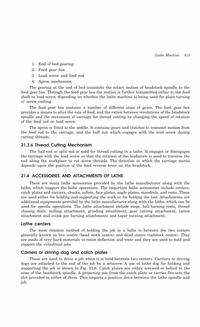
Lathe Machine 411
1. End of bed gearing2. Feed gear box3. Lead screw and feed rod4. Apron mechanism
The gearing at the end of bed transmits the rotary motion of headstock spindle to thefeed gear box. Through the feed gear box the motion is further transmitted either to the feedshaft or lead screw, depending on whether the lathe machine is being used for plain turningor screw cutting.
The feed gear box contains a number of different sizes of gears. The feed gear boxprovides a means to alter the rate of feed, and the ration between revolutions of the headstockspindle and the movement of carriage for thread cutting by changing the speed of rotationof the feed rod or lead screw.
The apron is fitted to the saddle. It contains gears and clutches to transmit motion fromthe feed rod to the carriage, and the half nut which engages with the lead screw duringcutting threads.
21.3.6 Thread Cutting MechanismThe half nut or split nut is used for thread cutting in a lathe. It engages or disengages
the carriage with the lead screw so that the rotation of the leadscrew is used to traverse thetool along the workpiece to cut screw threads. The direction in which the carriage movesdepends upon the position of the feed reverse lever on the headstock.
21.4 ACCESSORIES AND ATTACHMENTS OF LATHE
There are many lathe accessories provided by the lathe manufacturer along with thelathe, which support the lathe operations. The important lathe accessories include centers,catch plates and carriers, chucks, collets, face plates, angle plates, mandrels, and rests. Theseare used either for holding and supporting the work or for holding the tool. Attachments areadditional equipments provided by the lathe manufacturer along with the lathe, which can beused for specific operations. The lathe attachment include stops, ball turning rests, threadchasing dials, milling attachment, grinding attachment, gear cutting attachment, turretattachment and crank pin turning attachments and taper turning attachment.
Lathe centersThe most common method of holding the job in a lathe is between the two centers
generally known as live centre (head stock centre) and dead centre (tailstock centre). Theyare made of very hard materials to resist deflection and wear and they are used to hold andsupport the cylindrical jobs.
Carriers or driving dog and catch platesThese are used to drive a job when it is held between two centers. Carriers or driving
dogs are attached to the end of the job by a setscrew. A use of lathe dog for holding andsupporting the job is shown in Fig. 21.6. Catch plates are either screwed or bolted to thenose of the headstock spindle. A projecting pin from the catch plate or carrier fits into theslot provided in either of them. This imparts a positive drive between the lathe spindle andjob.

412 Introduction to Basic Manufacturing Processes and Workshop Technology
Lathe dog
Too l
Fig. 21.6 Lathe dog
ChucksChuck is one of the most important devices for holding and rotating a job in a lathe. It
is basically attached to the headstock spindle of the lathe. The internal threads in the chuckfit on to the external threads on the spindle nose. Short, cylindrical, hol1ow objects or thoseof irregular shapes, which cannot be conveniently mounted between centers, are easily andrigidly held in a chuck. Jobs of short length and large diameter or of irregular shape, whichcannot be conveniently mounted between centers, are held quickly and rigidly in a chuck.There are a number of types of lathe chucks, e.g.
(1) Three jaws or universal
(2) Four jaw independent chuck
(3) Magnetic chuck
(4) Collet chuck
(5) Air or hydraulic chuck operated chuck
(6) Combination chuck
(7) Drill chuck.
Face platesFace plates are employed for holding jobs, which cannot be conveniently held between
centers or by chucks. A face plate possesses the radial, plain and T slots for holding jobs orwork-pieces by bolts and clamps. Face plates consist of a circular disc bored out and threadedto fit the nose of the lathe spindle. They are heavily constructed and have strong thick ribson the back. They have slots cut into them, therefore nuts, bolts, clamps and angles are usedto hold the jobs on the face plate. They are accurately machined and ground.
Angle platesAngle plate is a cast iron plate having two faces machined to make them absolutely at
right angles to each other. Holes and slots are provided on both faces so that it may beclamped on a faceplate and can hold the job or workpiece on the other face by bolts andclamps. The plates are used in conjunction with a face plate when the holding surface of thejob should be kept horizontal.
MandrelsA mandrel is a device used for holding and rotating a hollow job that has been previously
drilled or bored. The job revolves with the mandrel, which is mounted between two centers.
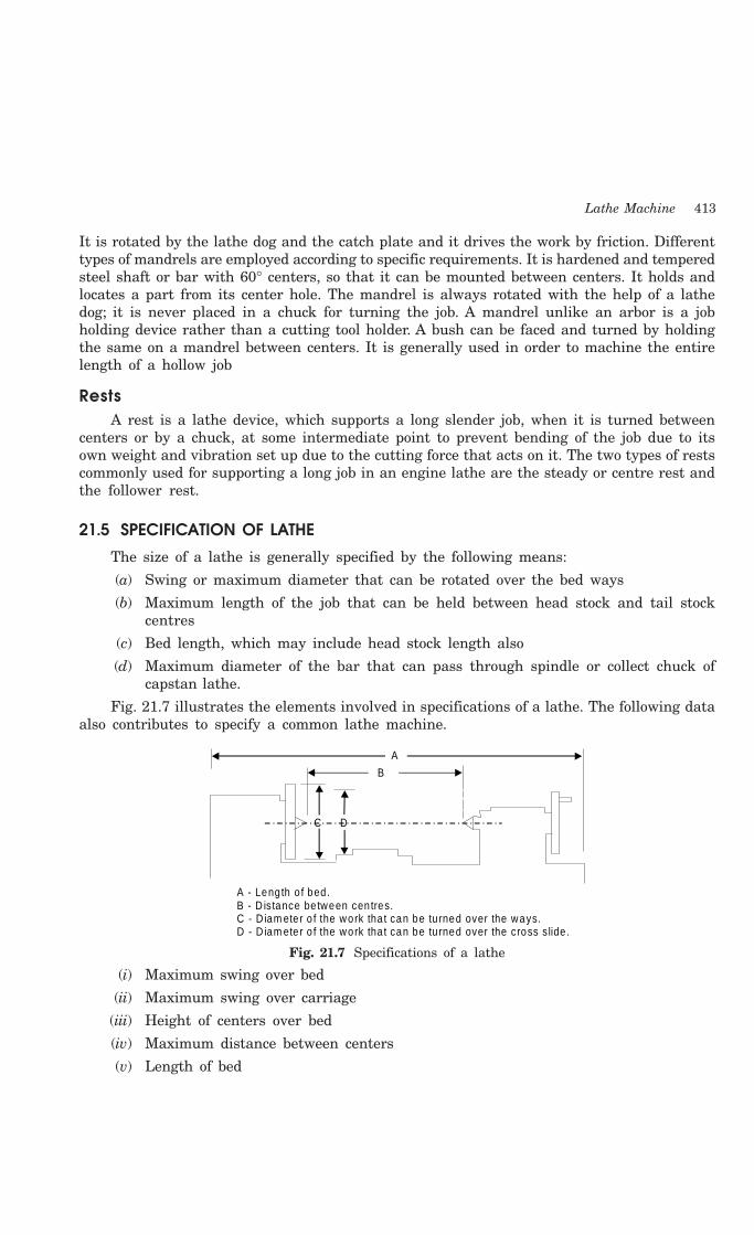
Lathe Machine 413
It is rotated by the lathe dog and the catch plate and it drives the work by friction. Differenttypes of mandrels are employed according to specific requirements. It is hardened and temperedsteel shaft or bar with 60° centers, so that it can be mounted between centers. It holds andlocates a part from its center hole. The mandrel is always rotated with the help of a lathedog; it is never placed in a chuck for turning the job. A mandrel unlike an arbor is a jobholding device rather than a cutting tool holder. A bush can be faced and turned by holdingthe same on a mandrel between centers. It is generally used in order to machine the entirelength of a hollow job
RestsA rest is a lathe device, which supports a long slender job, when it is turned between
centers or by a chuck, at some intermediate point to prevent bending of the job due to itsown weight and vibration set up due to the cutting force that acts on it. The two types of restscommonly used for supporting a long job in an engine lathe are the steady or centre rest andthe follower rest.
21.5 SPECIFICATION OF LATHE
The size of a lathe is generally specified by the following means:
(a) Swing or maximum diameter that can be rotated over the bed ways
(b) Maximum length of the job that can be held between head stock and tail stockcentres
(c) Bed length, which may include head stock length also
(d) Maximum diameter of the bar that can pass through spindle or collect chuck ofcapstan lathe.
Fig. 21.7 illustrates the elements involved in specifications of a lathe. The following dataalso contributes to specify a common lathe machine.
A
B
C D
A - Length o f bed .B - D istance be tween cen tres.C - D iam eter o f the work tha t can be tu rned over the ways.D - D iam eter o f the work tha t can be tu rned over the cross s lide .
Fig. 21.7 Specifications of a lathe
(i) Maximum swing over bed
(ii) Maximum swing over carriage
(iii) Height of centers over bed
(iv) Maximum distance between centers
(v) Length of bed
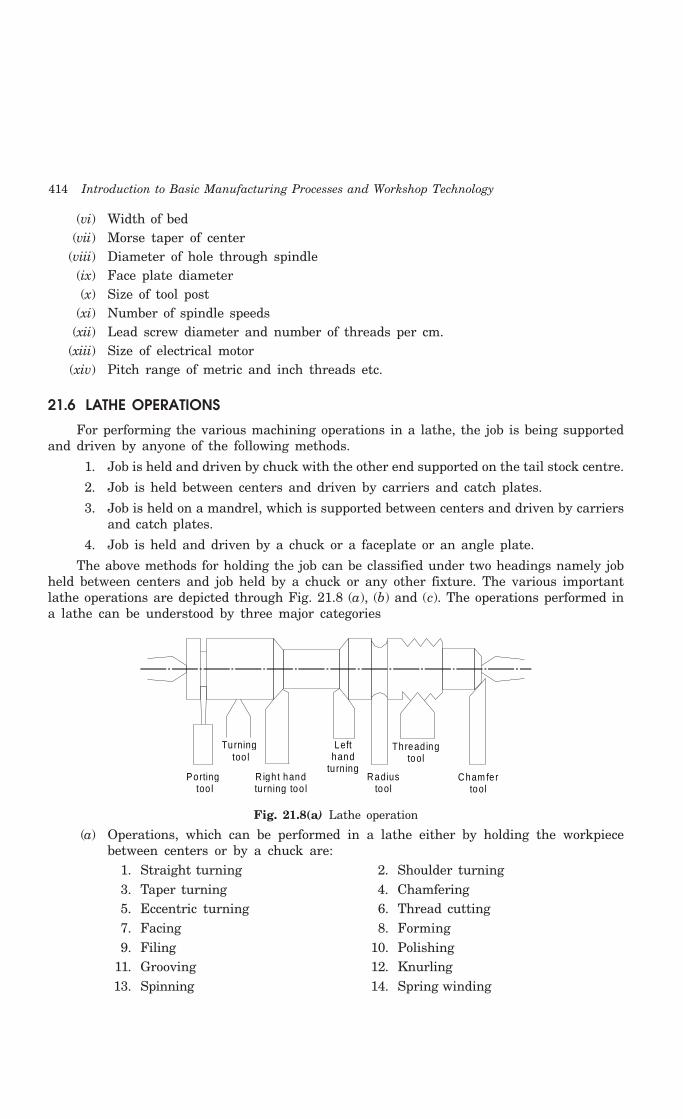
414 Introduction to Basic Manufacturing Processes and Workshop Technology
(vi) Width of bed(vii) Morse taper of center
(viii) Diameter of hole through spindle(ix) Face plate diameter(x) Size of tool post
(xi) Number of spindle speeds(xii) Lead screw diameter and number of threads per cm.
(xiii) Size of electrical motor(xiv) Pitch range of metric and inch threads etc.
21.6 LATHE OPERATIONS
For performing the various machining operations in a lathe, the job is being supportedand driven by anyone of the following methods.
1. Job is held and driven by chuck with the other end supported on the tail stock centre.
2. Job is held between centers and driven by carriers and catch plates.
3. Job is held on a mandrel, which is supported between centers and driven by carriersand catch plates.
4. Job is held and driven by a chuck or a faceplate or an angle plate.
The above methods for holding the job can be classified under two headings namely jobheld between centers and job held by a chuck or any other fixture. The various importantlathe operations are depicted through Fig. 21.8 (a), (b) and (c). The operations performed ina lathe can be understood by three major categories
Porting too l
Turning too l
R igh t hand tu rning too l
Left hand
tu rningRadius
tool
Thread ing tool
Cham fer tool
Fig. 21.8(a) Lathe operation
(a) Operations, which can be performed in a lathe either by holding the workpiecebetween centers or by a chuck are:
1. Straight turning 2. Shoulder turning3. Taper turning 4. Chamfering5. Eccentric turning 6. Thread cutting7. Facing 8. Forming9. Filing 10. Polishing
11. Grooving 12. Knurling13. Spinning 14. Spring winding
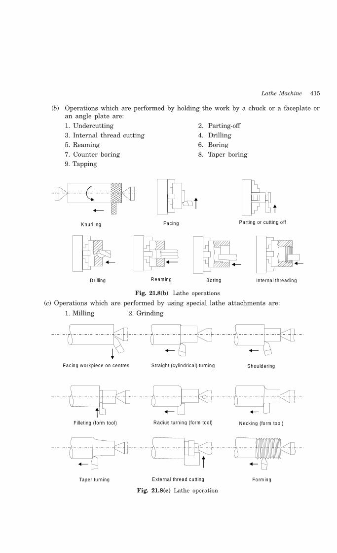
Lathe Machine 415
(b) Operations which are performed by holding the work by a chuck or a faceplate oran angle plate are:1. Undercutting 2. Parting-off3. Internal thread cutting 4. Drilling5. Reaming 6. Boring7. Counter boring 8. Taper boring9. Tapping
Knurlling Facing Parting or cutting o ff
Boring In te rna l thread ing D rilling Ream ing
Fig. 21.8(b) Lathe operations
(c) Operations which are performed by using special lathe attachments are:
1. Milling 2. Grinding
Facing workpiece on cen tres Straigh t (cy lindrical) tu rn ing Shou ldering
Filleting (form too l) Radius tu rn ing (form too l) Necking (fo rm tool)
Taper tu rning Exte rna l thread cu tting Form ing
Fig. 21.8(c) Lathe operation
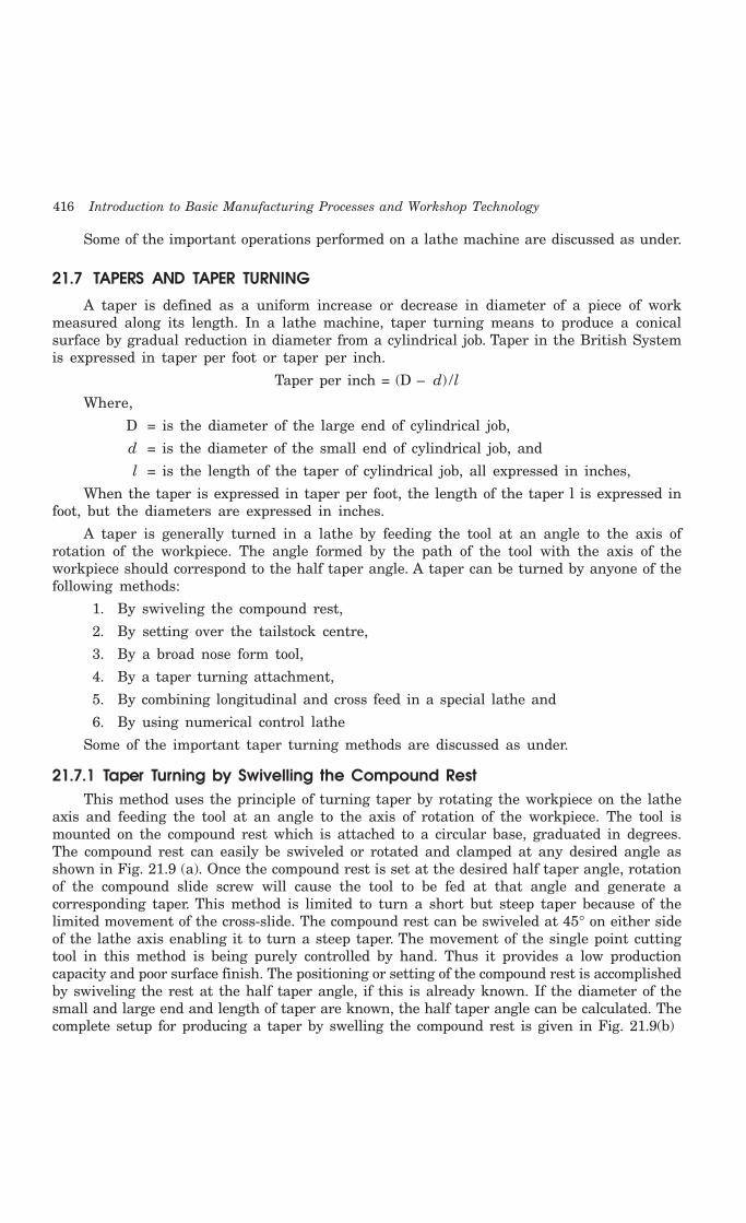
416 Introduction to Basic Manufacturing Processes and Workshop Technology
Some of the important operations performed on a lathe machine are discussed as under.
21.7 TAPERS AND TAPER TURNING
A taper is defined as a uniform increase or decrease in diameter of a piece of workmeasured along its length. In a lathe machine, taper turning means to produce a conicalsurface by gradual reduction in diameter from a cylindrical job. Taper in the British Systemis expressed in taper per foot or taper per inch.
Taper per inch = (D – d) /l
Where,
D = is the diameter of the large end of cylindrical job,
d = is the diameter of the small end of cylindrical job, and
l = is the length of the taper of cylindrical job, all expressed in inches,
When the taper is expressed in taper per foot, the length of the taper l is expressed infoot, but the diameters are expressed in inches.
A taper is generally turned in a lathe by feeding the tool at an angle to the axis ofrotation of the workpiece. The angle formed by the path of the tool with the axis of theworkpiece should correspond to the half taper angle. A taper can be turned by anyone of thefollowing methods:
1. By swiveling the compound rest,
2. By setting over the tailstock centre,
3. By a broad nose form tool,
4. By a taper turning attachment,
5. By combining longitudinal and cross feed in a special lathe and
6. By using numerical control lathe
Some of the important taper turning methods are discussed as under.
21.7.1 Taper Turning by Swivelling the Compound RestThis method uses the principle of turning taper by rotating the workpiece on the lathe
axis and feeding the tool at an angle to the axis of rotation of the workpiece. The tool ismounted on the compound rest which is attached to a circular base, graduated in degrees.The compound rest can easily be swiveled or rotated and clamped at any desired angle asshown in Fig. 21.9 (a). Once the compound rest is set at the desired half taper angle, rotationof the compound slide screw will cause the tool to be fed at that angle and generate acorresponding taper. This method is limited to turn a short but steep taper because of thelimited movement of the cross-slide. The compound rest can be swiveled at 45° on either sideof the lathe axis enabling it to turn a steep taper. The movement of the single point cuttingtool in this method is being purely controlled by hand. Thus it provides a low productioncapacity and poor surface finish. The positioning or setting of the compound rest is accomplishedby swiveling the rest at the half taper angle, if this is already known. If the diameter of thesmall and large end and length of taper are known, the half taper angle can be calculated. Thecomplete setup for producing a taper by swelling the compound rest is given in Fig. 21.9(b)
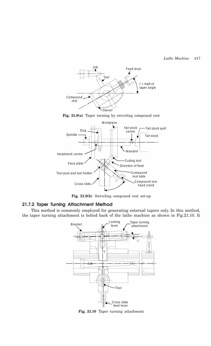
Lathe Machine 417
Job
Too l
Compound rest
Sw ive l
= Half o f taper ang le
Feed lever
Fig. 21.9(a) Taper turning by swiveling compound rest
DogSpindle
Headstock cen tre
Face p la te
Too l post and too l ho lder
Cross s lide
W orkp iece
Tail s tock cen tre
Tail s tock quill
Tail s tock
M andre l
Cutting tool
D irection of feed
Compound rest s lide
Compound rest hand crank
Fig. 21.9(b) Swiveling compound rest set-up
21.7.2 Taper Turning Attachment MethodThis method is commonly employed for generating external tapers only. In this method,
the taper turning attachment is bolted back of the lathe machine as shown in Fig.21.10. It
Too l
C ross s lidefeed lever
Bracke tLocking
leverTaper turning a ttachm ent
Job
T
Fig. 21.10 Taper turning attachment
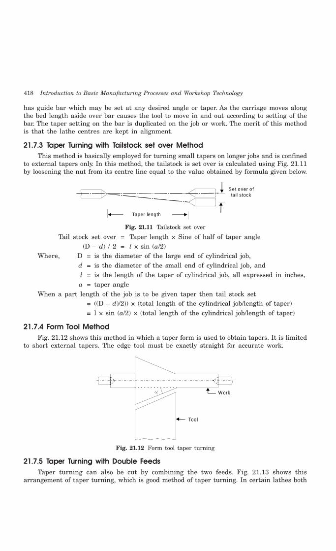
418 Introduction to Basic Manufacturing Processes and Workshop Technology
has guide bar which may be set at any desired angle or taper. As the carriage moves alongthe bed length aside over bar causes the tool to move in and out according to setting of thebar. The taper setting on the bar is duplicated on the job or work. The merit of this methodis that the lathe centres are kept in alignment.
21.7.3 Taper Turning with Tailstock set over MethodThis method is basically employed for turning small tapers on longer jobs and is confined
to external tapers only. In this method, the tailstock is set over is calculated using Fig. 21.11by loosening the nut from its centre line equal to the value obtained by formula given below.
Taper leng th
Set over o f ta il s tock
Fig. 21.11 Tailstock set over
Tail stock set over = Taper length × Sine of half of taper angle(D – d) / 2 = l × sin (a/2)
Where, D = is the diameter of the large end of cylindrical job,d = is the diameter of the small end of cylindrical job, andl = is the length of the taper of cylindrical job, all expressed in inches,a = taper angle
When a part length of the job is to be given taper then tail stock set= ((D – d)/2)) × (total length of the cylindrical job/length of taper)= l × sin (a/2) × (total length of the cylindrical job/length of taper)
21.7.4 Form Tool MethodFig. 21.12 shows this method in which a taper form is used to obtain tapers. It is limited
to short external tapers. The edge tool must be exactly straight for accurate work.
W ork
Too l
Fig. 21.12 Form tool taper turning
21.7.5 Taper Turning with Double FeedsTaper turning can also be cut by combining the two feeds. Fig. 21.13 shows this
arrangement of taper turning, which is good method of taper turning. In certain lathes both
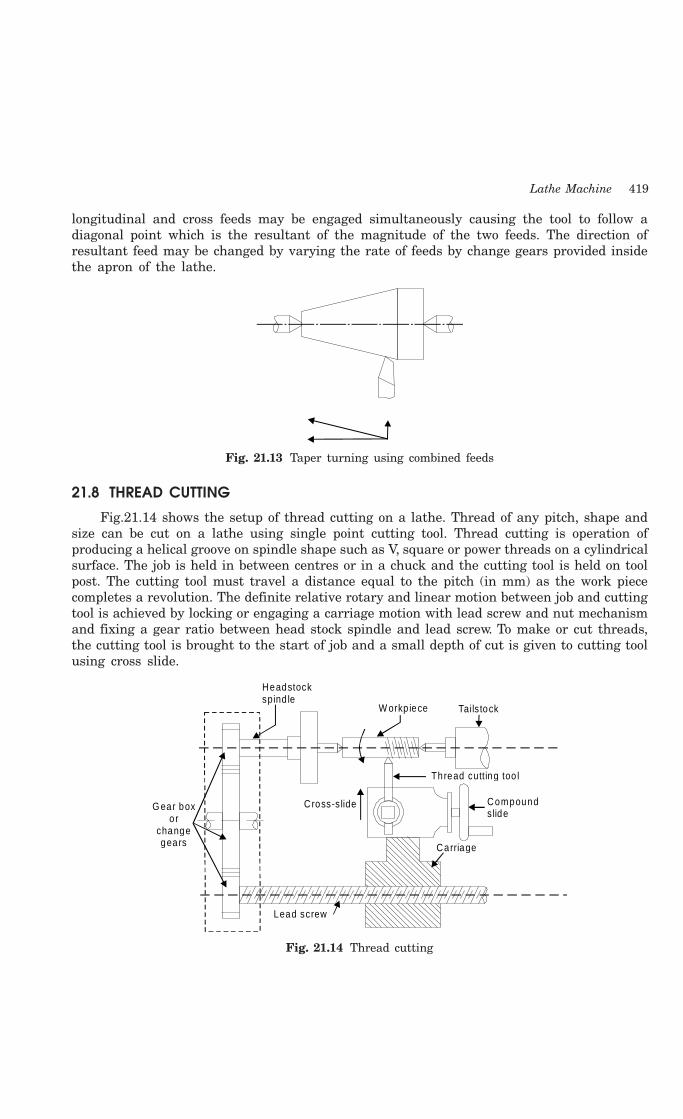
Lathe Machine 419
longitudinal and cross feeds may be engaged simultaneously causing the tool to follow adiagonal point which is the resultant of the magnitude of the two feeds. The direction ofresultant feed may be changed by varying the rate of feeds by change gears provided insidethe apron of the lathe.
Fig. 21.13 Taper turning using combined feeds
21.8 THREAD CUTTING
Fig.21.14 shows the setup of thread cutting on a lathe. Thread of any pitch, shape andsize can be cut on a lathe using single point cutting tool. Thread cutting is operation ofproducing a helical groove on spindle shape such as V, square or power threads on a cylindricalsurface. The job is held in between centres or in a chuck and the cutting tool is held on toolpost. The cutting tool must travel a distance equal to the pitch (in mm) as the work piececompletes a revolution. The definite relative rotary and linear motion between job and cuttingtool is achieved by locking or engaging a carriage motion with lead screw and nut mechanismand fixing a gear ratio between head stock spindle and lead screw. To make or cut threads,the cutting tool is brought to the start of job and a small depth of cut is given to cutting toolusing cross slide.
Cross-s lide
W orkp iece Tails tock
Carriage
Lead screw
G ear boxor
changegears
Compoundslide
Thread cutting too l
Headstockspind le
Fig. 21.14 Thread cutting
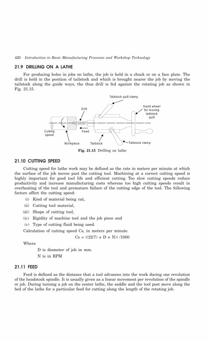
420 Introduction to Basic Manufacturing Processes and Workshop Technology
21.9 DRILLING ON A LATHE
For producing holes in jobs on lathe, the job is held in a chuck or on a face plate. Thedrill is held in the position of tailstock and which is brought nearer the job by moving thetailstock along the guide ways, the thus drill is fed against the rotating job as shown inFig. 21.15.
Drill
Tails tock quill clam p
Hand whee lfo r m oving
ta ilstock quill
Tails tock c lam pTails tock
FeedCutting speed
W orkp iece
Fig. 21.15 Drilling on lathe
21.10 CUTTING SPEED
Cutting speed for lathe work may be defined as the rate in meters per minute at whichthe surface of the job moves past the cutting tool. Machining at a correct cutting speed ishighly important for good tool life and efficient cutting. Too slow cutting speeds reduceproductivity and increase manufacturing costs whereas too high cutting speeds result inoverheating of the tool and premature failure of the cutting edge of the tool. The followingfactors affect the cutting speed:
(i) Kind of material being cut,
(ii) Cutting tool material,
(iii) Shape of cutting tool,
(iv) Rigidity of machine tool and the job piece and
(v) Type of cutting fluid being used.
Calculation of cutting speed Cs, in meters per minute
Cs = ((22/7) × D × N)) /1000
Where
D is diameter of job in mm.
N is in RPM
21.11 FEED
Feed is defined as the distance that a tool advances into the work during one revolutionof the headstock spindle. It is usually given as a linear movement per revolution of the spindleor job. During turning a job on the center lathe, the saddle and the tool post move along thebed of the lathe for a particular feed for cutting along the length of the rotating job.
Lathe Machine 421
22.12 QUESTIONS
1. Describe the working principle of the lathe.
2. Name the different types of the lathes available in machine shop? Describe the working ofa centre lathe.
3. Explain the parts of a centre lathe using neat sketch.
4. Explain following parts of a lathe by neat sketches:
(i) Lathe Bed (ii) Carriage (iii) Headstock (iv) Tailstock
5. How can you specify a lathe?
6. Name the operations, which can be performed on a lathe.
7. Lists the accessories of a lathe? Explain them with neat sketches.
8. Describe any two work holding devices used on the lathe.
9. What is the use of follower rest and steady rest?
10. Explain the difference between three jaw chuck and four jaw chuck.
11. Using neat sketches, describe the various operations that can be carried on lathe machines.
12. With the help of a line diagram, describe the gear mechanism of an engine lathe.
13. Discuss the merits and demerits of a geared-head drive over cone-pulley drive.
14. Name and sketch the different types of the cutting tools of the lathe.
15. Describe the procedure of cutting right hand V- heads of the lathe.
16. With help of neat diagram, describe the following:
(i) Finish turning
(ii) Rough turning
(iii) Turning
(iv) Drilling
(v) Attachments of lathe
17. Name different methods of taper turning? Describe these methods using neat sketches.
18. Describe with suitable sketch the procedure for turning a taper using setting over thetailstock.
19. Define the following terms used in lathe operation.
(i) Cutting speed
(ii) Feed
(iii) Depth of cut
(iv) Machining time

422 Introduction to Basic Manufacturing Processes and Workshop Technology
422
DRILLING MACHINE
22.1 INTRODUCTION
Drilling is an operation of making a circular hole by removing a volume of metal fromthe job by cutting tool called drill. A drill is a rotary end-cutting tool with one or more cuttinglips and usually one or more flutes for the passage of chips and the admission of cutting fluid.A drilling machine is a machine tool designed for drilling holes in metals. It is one of the mostimportant and versatile machine tools in a workshop. Besides drilling round holes, manyother operations can also be performed on the drilling machine such as counter- boring,countersinking, honing, reaming, lapping, sanding etc.
22.2 CONSTRUCTION OF DRILLING MACHINE
In drilling machine the drill is rotated and fed along its axis of rotation in the stationaryworkpiece. Different parts of a drilling machine are shown in Fig. 22.1 and are discussedbelow: (i) The head containing electric motor, V-pulleys and V-belt which transmit rotarymotion to the drill spindle at a number of speeds. (ii) Spindle is made up of alloy steel. Itrotates as well as moves up and down in a sleeve. A pinion engages a rack fixed onto thesleeve to provide vertical up and down motion of the spindle and hence the drill so that thesame can be fed into the workpiece or withdrawn from it while drilling. Spindle speed or thedrill speed is changed with the help of V-belt and V-step-pulleys. Larger drilling machines arehaving gear boxes for the said purpose. (iii) Drill chuck is held at the end of the drill spindleand in turn it holds the drill bit. (iv) Adjustable work piece table is supported on the columnof the drilling machine. It can be moved both vertically and horizontally. Tables are generallyhaving slots so that the vise or the workpiece can be securely held on it. (v) Base table isa heavy casting and it supports the drill press structure. The base supports the column, whichin turn, supports the table, head etc. (vi) Column is a vertical round or box section which restson the base and supports the head and the table. The round column may have rack teeth cuton it so that the table can be raised or lowered depending upon the workpiece requirements.This machine consists of following parts
1. Base
2. Pillar
3. Main drive
4. Drill spindle
22CHAPTER
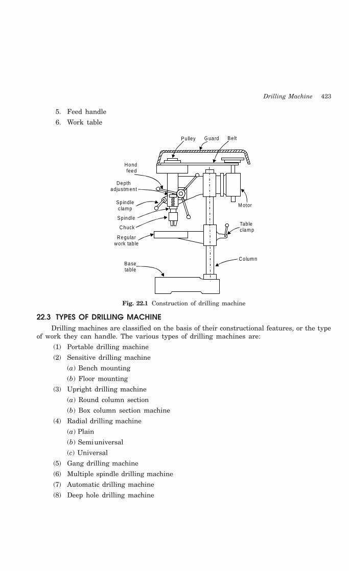
Drilling Machine 423
5. Feed handle
6. Work table
Hond feed
Depth adjustm ent
Sp indle c lamp
Spindle
Chuck
Regu la r work tab le
Base table
M otor
Tab le c lam p
Column
Pulley G uard Be lt
Fig. 22.1 Construction of drilling machine
22.3 TYPES OF DRILLING MACHINEDrilling machines are classified on the basis of their constructional features, or the type
of work they can handle. The various types of drilling machines are:
(1) Portable drilling machine
(2) Sensitive drilling machine
(a) Bench mounting
(b) Floor mounting
(3) Upright drilling machine
(a) Round column section
(b) Box column section machine
(4) Radial drilling machine
(a) Plain
(b) Semiuniversal
(c) Universal
(5) Gang drilling machine
(6) Multiple spindle drilling machine
(7) Automatic drilling machine
(8) Deep hole drilling machine

424 Introduction to Basic Manufacturing Processes and Workshop Technology
(a) Vertical
(b) HorizontalFew commonly used drilling machines are described as under.
22.3.1 Portable Drilling MachineA portable drilling machine is a small compact unit and used for drilling holes in worpieces
in any position, which cannot be drilled in a standard drilling machine. It may be used fordrilling small diameter holes in large castings or weldments at that place itself where theyare lying. Portable drilling machines are fitted with small electric motors, which may bedriven by both A.C. and D.C. power supply. These drilling machines operate at fairly highspeeds and accommodate drills up to 12 mm in diameter.
22.3.2 Sensitive Drilling MachineIt is a small machine used for drilling small holes in light jobs. In this drilling machine,
the workpiece is mounted on the table and drill is fed into the work by purely hand control.High rotating speed of the drill and hand feed are the major features of sensitive drillingmachine. As the operator senses the drilling action in the workpiece, at any instant, it iscalled sensitive drilling machine. A sensitive drilling machine consists of a horizontal table,a vertical column, a head supporting the motor and driving mechanism, and a vertical spindle.Drills of diameter from 1.5 to 15.5 mm can be rotated in the spindle of sensitive drillingmachine. Depending on the mounting of base of the machine, it may be classified intofollowing types:
1. Bench mounted drilling machine, and
2. Floor mounted drilling machine
22.3.3 Upright Drilling MachineThe upright drilling machine is larger and heavier than a sensitive drilling machine. It
is designed for handling medium sized workpieces and is supplied with power feed arrangement.In this machine a large number of spindle speeds and feeds may be available for drillingdifferent types of work. Upright drilling machines are available in various sizes and withvarious drilling capacities (ranging up to 75 mm diameter drills). The table of the machinealso has different types of adjustments. Based on the construction, there are two generaltypes of upright drilling machine:
(1) Round column section or pillar drilling machine.
(2) Box column section.
The round column section upright drilling machine consists of a round column whereasthe upright drilling machine has box column section. The other constructional features ofboth are same. Box column machines possess more machine strength and rigidity as comparedto those having round section column.
22.3.4 Radial Drilling MachineFig. 22.2 illustrates a radial drilling machine. The radial drilling machine consists of a
heavy, round vertical column supporting a horizontal arm that carries the drill head. Arm canbe raised or lowered on the column and can also be swung around to any position over thework and can be locked in any position. The drill head containing mechanism for rotating and
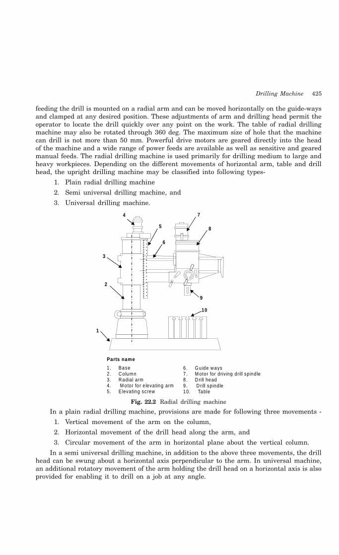
Drilling Machine 425
feeding the drill is mounted on a radial arm and can be moved horizontally on the guide-waysand clamped at any desired position. These adjustments of arm and drilling head permit theoperator to locate the drill quickly over any point on the work. The table of radial drillingmachine may also be rotated through 360 deg. The maximum size of hole that the machinecan drill is not more than 50 mm. Powerful drive motors are geared directly into the headof the machine and a wide range of power feeds are available as well as sensitive and gearedmanual feeds. The radial drilling machine is used primarily for drilling medium to large andheavy workpieces. Depending on the different movements of horizontal arm, table and drillhead, the upright drilling machine may be classified into following types-
1. Plain radial drilling machine
2. Semi universal drilling machine, and
3. Universal drilling machine.
1
2
3
4
5
6
7
8
9
10
Parts name
1. Base2. Co lumn3. Radial arm4. M otor fo r e leva ting arm5. E levating screw
6. G u ide ways7 . M otor for driving d rill spind le8 . D rill head9. D rill spind le10. Table
Fig. 22.2 Radial drilling machine
In a plain radial drilling machine, provisions are made for following three movements -
1. Vertical movement of the arm on the column,
2. Horizontal movement of the drill head along the arm, and
3. Circular movement of the arm in horizontal plane about the vertical column.
In a semi universal drilling machine, in addition to the above three movements, the drillhead can be swung about a horizontal axis perpendicular to the arm. In universal machine,an additional rotatory movement of the arm holding the drill head on a horizontal axis is alsoprovided for enabling it to drill on a job at any angle.

426 Introduction to Basic Manufacturing Processes and Workshop Technology
22.3.5 Gang Drilling MachineIn gang drilling machine, a number of single spindle drilling machine columns are placed
side by side on a common base and have a common worktable. A series of operation may beperformed on the job by shifting the work from one position to the other on the worktable.This type of machine is mainly used for production work.
22.3.6 Multiple-Spindle Drilling MachineThe multiple-spindle drilling machine is used to drill a number of holes in a job
simultaneously and to reproduce the same pattern of holes in a number of identical pieces ina mass production work. This machine has several spindles and all the spindles holding drillsare fed into the work simultaneously. Feeding motion is usually obtained by raising the worktable.
22.4 TYPES OF DRILLS
A drill is a multi point cutting tool used to produce or enlarge a hole in the workpiece.It usually consists of two cutting edges set an angle with the axis. Broadly there are threetypes of drills:
1. Flat drill,
2. Straight-fluted drill, and
3. Twist drill
Flat drill is usually made from a piece of round steel which is forged to shape and groundto size, then hardened and tempered. The cutting angle is usually 90 deg. and the relief orclearance at the cutting edge is 3 to 8 deg. The disadvantage of this type of drill is that eachtime the drill is ground the diameter is reduced. Twist drill is the most common type of drillin use today. The various types of twist drills (parallel shank type and Morse taper shanktype) are shown in Fig. 22.3
Ton gu e
R e ce s
F lu te
H e el
L an d
Bod
yS
hank
Par
alle
l
Dril
l ax
is
Bod
y- le
ngth
Ove
rall
leng
th
Lea
d of
he
lix
Flu
te le
ngth
F lu te ru n-o ut
P a ra lle l sh a n ktyp e
M ors e ta pe r sha nk typ e
Fig. 22.3 Types of twist drill

Drilling Machine 427
Number sizesIn metric system, the drill is generally manufactured from 0.2 to 100 mm. In British
system the drills sizes range from No. 1 to No. 80. Number 80 is the smallest having diameterequal to 0.0135 inch and the number 1 is the largest having diameter equal to 0.228 inch.Number 1 to number 60 is the standard sets of drills. The numbers 61 to 80 sizes drills arenot so commonly used. The diameter of drills increases in steps of approximately by 0.002 inch.
Letter sizes The drill sizes range from A to Z, A being the smallest having diameter equal to 0.234
inch and Z being the largest having diameter equal to 0.413 inch, increasing in steps ofapproximately O.010 inch fractional sizes: The drill sizes range from 1/64" inch to 5 inch insteps of 1/64 inches up to 1.75 inches, then the steps gradually increase. The drill sizes rangefrom A to Z, A being the smallest having diameter equal to 0.234 inch and Z being the largesthaving diameter equal to 0.413 inch, increasing in steps of approximately O.010 inch fractionalsizes: The drill sizes range from 1/64" inch to 5 inch in steps of 1/64 inches up to 1.75 inches,then the steps gradually increase.
The drill is generally removed by tapping a wedge shaped drift into the slot in the drillingmachine spindle as shown in Fig. 22.4.
Slot
W edge shapeddrift
D rilling m ach ine spind le socke t
Tw ist d rillshank
Fig. 22.4 Removing a drill from drill machine
22.4.1 Twist Drill GeometryTwist drill geometry and its nomenclature are shown in Fig. 22.5. A twist drill has three
principal parts:
(i) Drill point or dead center
(ii) Body
(iii) Shank.
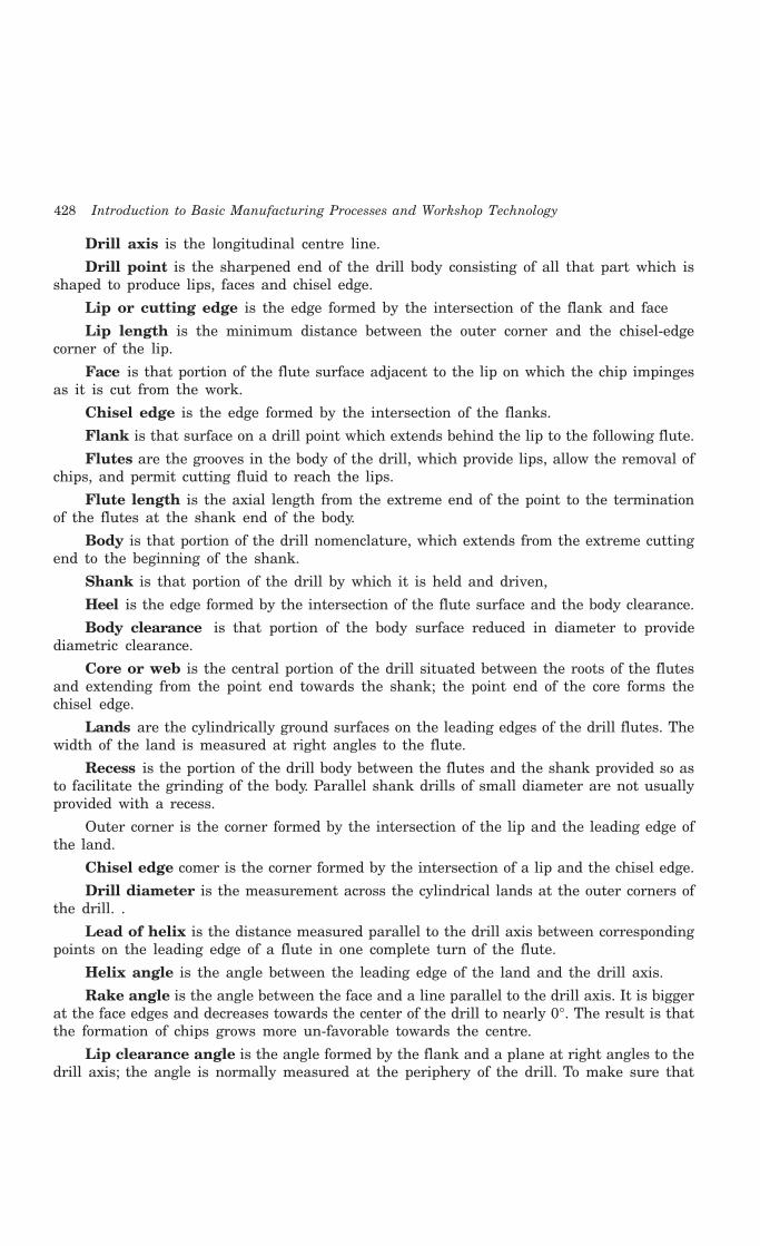
428 Introduction to Basic Manufacturing Processes and Workshop Technology
Drill axis is the longitudinal centre line.
Drill point is the sharpened end of the drill body consisting of all that part which isshaped to produce lips, faces and chisel edge.
Lip or cutting edge is the edge formed by the intersection of the flank and face
Lip length is the minimum distance between the outer corner and the chisel-edgecorner of the lip.
Face is that portion of the flute surface adjacent to the lip on which the chip impingesas it is cut from the work.
Chisel edge is the edge formed by the intersection of the flanks.
Flank is that surface on a drill point which extends behind the lip to the following flute.
Flutes are the grooves in the body of the drill, which provide lips, allow the removal ofchips, and permit cutting fluid to reach the lips.
Flute length is the axial length from the extreme end of the point to the terminationof the flutes at the shank end of the body.
Body is that portion of the drill nomenclature, which extends from the extreme cuttingend to the beginning of the shank.
Shank is that portion of the drill by which it is held and driven,
Heel is the edge formed by the intersection of the flute surface and the body clearance.
Body clearance is that portion of the body surface reduced in diameter to providediametric clearance.
Core or web is the central portion of the drill situated between the roots of the flutesand extending from the point end towards the shank; the point end of the core forms thechisel edge.
Lands are the cylindrically ground surfaces on the leading edges of the drill flutes. Thewidth of the land is measured at right angles to the flute.
Recess is the portion of the drill body between the flutes and the shank provided so asto facilitate the grinding of the body. Parallel shank drills of small diameter are not usuallyprovided with a recess.
Outer corner is the corner formed by the intersection of the lip and the leading edge ofthe land.
Chisel edge comer is the corner formed by the intersection of a lip and the chisel edge.
Drill diameter is the measurement across the cylindrical lands at the outer corners ofthe drill. .
Lead of helix is the distance measured parallel to the drill axis between correspondingpoints on the leading edge of a flute in one complete turn of the flute.
Helix angle is the angle between the leading edge of the land and the drill axis.
Rake angle is the angle between the face and a line parallel to the drill axis. It is biggerat the face edges and decreases towards the center of the drill to nearly 0°. The result is thatthe formation of chips grows more un-favorable towards the centre.
Lip clearance angle is the angle formed by the flank and a plane at right angles to thedrill axis; the angle is normally measured at the periphery of the drill. To make sure that
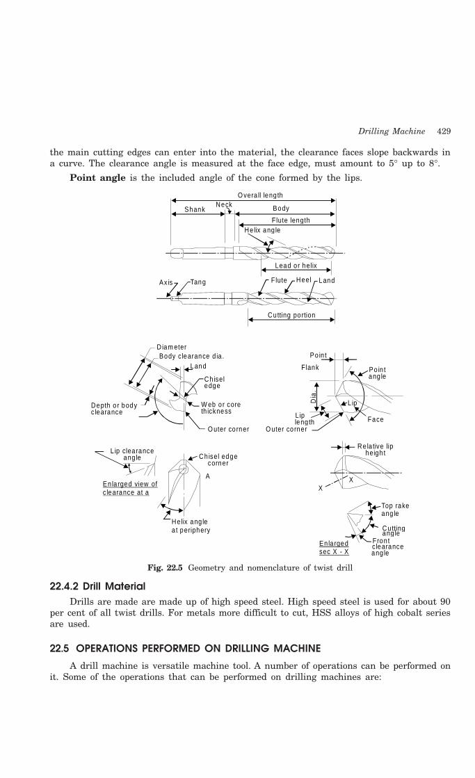
Drilling Machine 429
the main cutting edges can enter into the material, the clearance faces slope backwards ina curve. The clearance angle is measured at the face edge, must amount to 5° up to 8°.
Point angle is the included angle of the cone formed by the lips.
O vera ll leng thNeck BodyShank
He lix ang leFlute length
Lead or helix
Flute Heel LandAxis Tang
Cutting portion
D iam eterBody c learance d ia .
Land
Chiseledge
W eb or coreth ickness
Depth o r bodyclearance
L ip clearanceang le Ch isel edge
corner
L ipleng th
O uter corner
Re la tive lipheigh t
Face
L ipDia
.
F lank Po in tang le
Po in t
A
XX
Helix ang lea t periphery
En la rged view ofc learance at a
Top rakeang le
Cuttingang le
Fron tc learanceang le
En la rgedsec X - X
O uter corner
Fig. 22.5 Geometry and nomenclature of twist drill
22.4.2 Drill MaterialDrills are made are made up of high speed steel. High speed steel is used for about 90
per cent of all twist drills. For metals more difficult to cut, HSS alloys of high cobalt seriesare used.
22.5 OPERATIONS PERFORMED ON DRILLING MACHINE
A drill machine is versatile machine tool. A number of operations can be performed onit. Some of the operations that can be performed on drilling machines are:
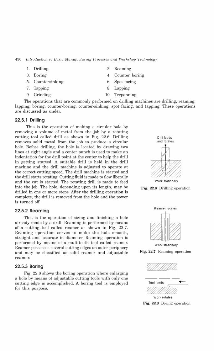
430 Introduction to Basic Manufacturing Processes and Workshop Technology
1. Drilling 2. Reaming
3. Boring 4. Counter boring
5. Countersinking 6. Spot facing
7. Tapping 8. Lapping
9. Grinding 10. Trepanning.
The operations that are commonly performed on drilling machines are drilling, reaming,lapping, boring, counter-boring, counter-sinking, spot facing, and tapping. These operationsare discussed as under.
22.5.1 Drilling This is the operation of making a circular hole by
removing a volume of metal from the job by a rotatingcutting tool called drill as shown in Fig. 22.6. Drillingremoves solid metal from the job to produce a circularhole. Before drilling, the hole is located by drawing twolines at right angle and a center punch is used to make anindentation for the drill point at the center to help the drillin getting started. A suitable drill is held in the drillmachine and the drill machine is adjusted to operate atthe correct cutting speed. The drill machine is started andthe drill starts rotating. Cutting fluid is made to flow liberallyand the cut is started. The rotating drill is made to feedinto the job. The hole, depending upon its length, may bedrilled in one or more steps. After the drilling operation iscomplete, the drill is removed from the hole and the poweris turned off.
22.5.2 ReamingThis is the operation of sizing and finishing a hole
already made by a drill. Reaming is performed by meansof a cutting tool called reamer as shown in Fig. 22.7.Reaming operation serves to make the hole smooth,straight and accurate in diameter. Reaming operation isperformed by means of a multitooth tool called reamer.Reamer possesses several cutting edges on outer peripheryand may be classified as solid reamer and adjustablereamer.
22.5.3 BoringFig. 22.8 shows the boring operation where enlarging
a hole by means of adjustable cutting tools with only onecutting edge is accomplished. A boring tool is employedfor this purpose.
W ork sta tionary
Ream er rota tes
Fig. 22.7 Reaming operation
Drill feedsand rotates
W ork sta tionary
Fig. 22.6 Drilling operation
Too l fee ds
W ork ro ta tes
Fig. 22.8 Boring operation
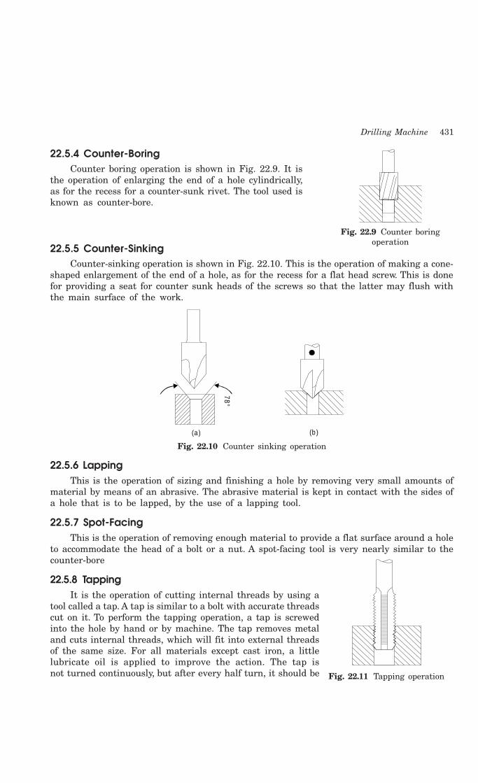
Drilling Machine 431
22.5.4 Counter-BoringCounter boring operation is shown in Fig. 22.9. It is
the operation of enlarging the end of a hole cylindrically,as for the recess for a counter-sunk rivet. The tool used isknown as counter-bore.
22.5.5 Counter-SinkingCounter-sinking operation is shown in Fig. 22.10. This is the operation of making a cone-
shaped enlargement of the end of a hole, as for the recess for a flat head screw. This is donefor providing a seat for counter sunk heads of the screws so that the latter may flush withthe main surface of the work.
78°
(a ) (b )
Fig. 22.10 Counter sinking operation
22.5.6 LappingThis is the operation of sizing and finishing a hole by removing very small amounts of
material by means of an abrasive. The abrasive material is kept in contact with the sides ofa hole that is to be lapped, by the use of a lapping tool.
22.5.7 Spot-FacingThis is the operation of removing enough material to provide a flat surface around a hole
to accommodate the head of a bolt or a nut. A spot-facing tool is very nearly similar to thecounter-bore
22.5.8 TappingIt is the operation of cutting internal threads by using a
tool called a tap. A tap is similar to a bolt with accurate threadscut on it. To perform the tapping operation, a tap is screwedinto the hole by hand or by machine. The tap removes metaland cuts internal threads, which will fit into external threadsof the same size. For all materials except cast iron, a littlelubricate oil is applied to improve the action. The tap isnot turned continuously, but after every half turn, it should be
Fig. 22.9 Counter boringoperation
Fig. 22.11 Tapping operation

432 Introduction to Basic Manufacturing Processes and Workshop Technology
reversed slightly to clear the threads. Tapping operation is shown in Fig.22.11. The geometryand nomenclature of a tap is given in Fig. 22.12.
O vera ll leng th Shank leng th Thread leng th
Cham fer Length o f square
D riving cen tre
Shank dia Exte rna l cen tre
In te rna l cen tre
Po in t d ia W eb d ie
S ize o f source
Axis
Cutting edge
Heel
Unrelieved land Re lived
Positive Rack ang le Land Negative
rake ang le
P itch Flank ang le
Basic he ight o f th read
M ax. Tapm ajor
M in .Tap m ajor
d ia
Basic m ajor
d ia Re lieved to
cutting edge
Basic m inor dia
Basic e ffective
d ia
Flute
Cham fer re lie f
Cutte r edge
Heel
Face
Fig. 22.12 Geometry and nomenclature of tap
22.5.9 Core drillingCore drilling operation is shown in Fig. 22.13. It is a main
operation, which is performed on radial drilling machine forproducing a circular hole, which is deep in the solid metal bymeans of revolving tool called drill.
22.6 SIZE OF A DRILLING MACHINE
Different parameters are being considered for differenttypes of drilling machines to determine their size. The size ofa portable drilling machine is decided by the maximum diameterof the drill that it can hold. The sensitive and upright drillingmachines are specified by the diameter of the largest workpiece which can be centered underthe drill machine spindle. A radial drilling machine is specified by the length of the arm andthe diameter of the column. To specify a drilling machine completely, following other parametersmay also be needed:
1. Table diameter2. Number of spindle speeds and feeds available3. Maximum spindle travel4. Morse taper number of the drill spindle5. Power input6. Net weight of the machine7. Floor space required, etc.
Fig. 22.13 Core drillingoperation

Drilling Machine 433
22.7 CUTTING SPEED
The cutting speed in a drilling operation refers to the peripheral speed of a point on thesurface of the drill in contact with the work. It is usually expressed in meters/min. Thecutting speed (Cs) may be calculated as:
Cs = ((22/7) × D × N)/1000
Where, D is the diameter of the drill in mm and
N is the rpm of the drill spindle.
22.8 FEED
The feed of a drill is the distance the drill moves into the job at each revolution of thespindle. It is expressed in millimeter. The feed may also be expressed as feed per minute. Thefeed per minute may be defined as the axial distance moved by the drill into the work perminute. The feed per minute may be calculated as:
F = Fr × N
Where, F = Feed per minute in mm.
Fr = Feed per revolution in mm.
N = R.P.M. of the drill.
22.9 QUESTIONS1. State the working principle of a drilling machine.
2. Explain principal parts of the drilling machine and sketch the mechanism of a drillingmachine.
3. Give the classification of drilling machines.
4. How will you specify a drilling machine?
5. What operations can be done on a drilling machine? Discuss them with diagrams.
6. With the help of a line diagram, describe the construction of radial drilling machine.
7. List the devices commonly used for holding the work on a drilling machine, and describe any three.
8. Define cutting speed, feed and machining time for drilling.
9. Sketch a twist drill and name its different parts.
10. What is boring? Sketch a boring tool.
11. What is the function of flutes on a twist drill bit? Why are straight flute drills used for non-ferrous materials and metal?
12. Draw suitable figure for a drill bit showing:
(i) point (ii) lip clearance (iii) point angle (iv) flute (v) margin and (vi) body clearance
13 Write short notes on following:
(i) Drilling (ii) Boring, (iii) Reaming (iv) Tapping (v) Counter boring (vi) Counter sinking
14. Explain various types of operations performed on a drilling machine by neat sketches.
15. Define the following terms used in drilling operation.
(i) Cutting speed (ii) Feed
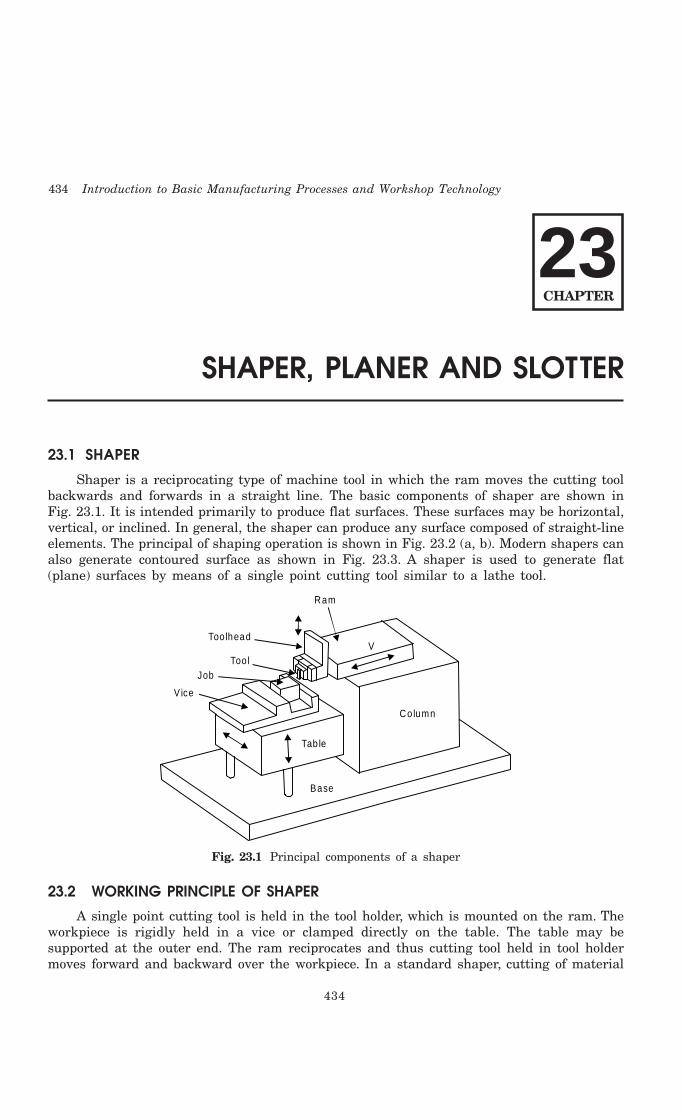
434 Introduction to Basic Manufacturing Processes and Workshop Technology
434
SHAPER, PLANER AND SLOTTER
23.1 SHAPER
Shaper is a reciprocating type of machine tool in which the ram moves the cutting toolbackwards and forwards in a straight line. The basic components of shaper are shown inFig. 23.1. It is intended primarily to produce flat surfaces. These surfaces may be horizontal,vertical, or inclined. In general, the shaper can produce any surface composed of straight-lineelements. The principal of shaping operation is shown in Fig. 23.2 (a, b). Modern shapers canalso generate contoured surface as shown in Fig. 23.3. A shaper is used to generate flat(plane) surfaces by means of a single point cutting tool similar to a lathe tool.
Column
Tab le
Base
Vice
JobToo l
Too lhead
Ram
V
Fig. 23.1 Principal components of a shaper
23.2 WORKING PRINCIPLE OF SHAPER
A single point cutting tool is held in the tool holder, which is mounted on the ram. Theworkpiece is rigidly held in a vice or clamped directly on the table. The table may besupported at the outer end. The ram reciprocates and thus cutting tool held in tool holdermoves forward and backward over the workpiece. In a standard shaper, cutting of material
23CHAPTER
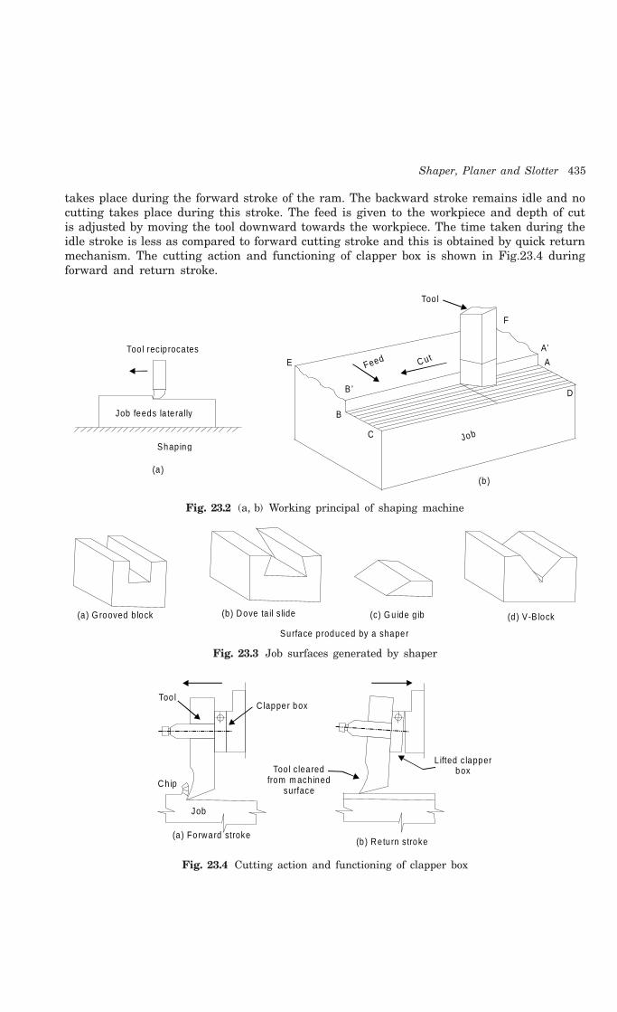
Shaper, Planer and Slotter 435
takes place during the forward stroke of the ram. The backward stroke remains idle and nocutting takes place during this stroke. The feed is given to the workpiece and depth of cutis adjusted by moving the tool downward towards the workpiece. The time taken during theidle stroke is less as compared to forward cutting stroke and this is obtained by quick returnmechanism. The cutting action and functioning of clapper box is shown in Fig.23.4 duringforward and return stroke.
Job feeds la te rally
Too l rec ip roca tes
Shap ing
A’
B
B ’
C
D
E
F
AFeed C ut
Job
Too l
(a )(b )
Fig. 23.2 (a, b) Working principal of shaping machine
(a ) G rooved b lock (b) Dove ta il s lide (c) G u ide g ib (d ) V-B lock
Surface p roduced by a shaper
Fig. 23.3 Job surfaces generated by shaper
Too lC lapper box
Ch ip
Too l c leared from m ach ined
surface
L ifted c lapper box
(a) Forward stroke (b ) Retu rn stroke
Job
Fig. 23.4 Cutting action and functioning of clapper box

436 Introduction to Basic Manufacturing Processes and Workshop Technology
23.3 TYPES OF SHAPERS
Shapers are classified under the following headings:(1) According to the type of mechanism used for giving reciprocating motion to the ram
(a) Crank type(b) Geared type(c) Hydraulic type
(2) According to the type of design of the table:(a) Standard shaper(b) Universal shaper
(3) According to the position and travel of ram:(a) Horizontal type(b) Vertical type(c) Traveling head type
(4) According to the type of cutting stroke:(a) Push type(b) Draw type.
A brief description these shapers is given below-
23.3.1 Crank Shaper This is the most common type of shaper. It employs a crank mechanism to change
circular motion of a large gear called “bull gear” incorporated in the machine to reciprocatingmotion of the ram. The bull gear receives power either from an individual motor or from anoverhead line shaft if it is a belt-driven shaper.
23.3.2 Geared ShaperGeared shaper uses rack and pinion arrangement to obtain reciprocating motion of the
ram. Presently this type of shaper is not very widely used.
23.3.3 Hydraulic ShaperIn hydraulic shaper, reciprocating motion of the ram is obtained by hydraulic power. For
generation of hydraulic power, oil under high pressure is pumped into the operating cylinderfitted with piston. The piston end is connected to the ram through piston rod. The highpressure oil causes the piston to reciprocate and this reciprocating motion is transferred tothe ram of shaper. The important advantage of this type of shaper is that the cutting speedand force of the ram drive are constant from the very beginning to the end of the cut.
23.3.4 Standard ShaperIn standard shaper, the table has only two movements, horizontal and vertical, to give
the feed.
23.3.5 Universal ShaperA universal shaper is mostly used in tool room work. In this type of shaper, in addition
to the horizontal and vertical movements, the table can be swiveled about an axis parallel to
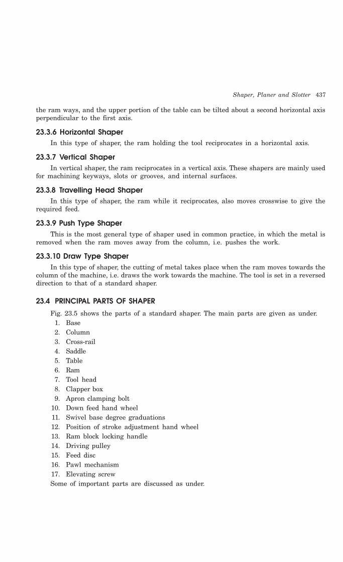
Shaper, Planer and Slotter 437
the ram ways, and the upper portion of the table can be tilted about a second horizontal axisperpendicular to the first axis.
23.3.6 Horizontal ShaperIn this type of shaper, the ram holding the tool reciprocates in a horizontal axis.
23.3.7 Vertical ShaperIn vertical shaper, the ram reciprocates in a vertical axis. These shapers are mainly used
for machining keyways, slots or grooves, and internal surfaces.
23.3.8 Travelling Head ShaperIn this type of shaper, the ram while it reciprocates, also moves crosswise to give the
required feed.
23.3.9 Push Type ShaperThis is the most general type of shaper used in common practice, in which the metal is
removed when the ram moves away from the column, i.e. pushes the work.
23.3.10 Draw Type ShaperIn this type of shaper, the cutting of metal takes place when the ram moves towards the
column of the machine, i.e. draws the work towards the machine. The tool is set in a reverseddirection to that of a standard shaper.
23.4 PRINCIPAL PARTS OF SHAPER
Fig. 23.5 shows the parts of a standard shaper. The main parts are given as under.1. Base2. Column3. Cross-rail4. Saddle5. Table6. Ram7. Tool head8. Clapper box9. Apron clamping bolt
10. Down feed hand wheel11. Swivel base degree graduations12. Position of stroke adjustment hand wheel13. Ram block locking handle14. Driving pulley15. Feed disc16. Pawl mechanism17. Elevating screwSome of important parts are discussed as under.

438 Introduction to Basic Manufacturing Processes and Workshop Technology
Tab le
Vise
W ork
Too l
Too l postToo l s lide
Vertica l too l feed hand w heel
Tab lesupport
Base
Tab le cross feed m echan ism
Cross ra il saddle
Ram
Driving m echan ism
Column
Foundation bolts
Ram lock ing clapShaper head
Sw ive l clam p Ram position Control nu t
Fig. 23.5 Parts of a standard shaper
BaseIt is rigid and heavy cast iron body to resist vibration and takes up high compressive
load. It supports all other parts of the machine, which are mounted over it. The base maybe rigidly bolted to the floor of the shop or on the bench according to the size of the machine.
ColumnThe column is a box shaped casting mounted upon the base. It houses the ram-driving
mechanism. Two accurately machined guide ways are provided on the top of the column onwhich the ram reciprocates.
Cross railCross rail of shaper has two parallel guide ways on its top in the vertical plane that is
perpendicular to the rai1 axis. It is mounted on the front vertical guide ways of the column.It consists mechanism for raising and lowering the table to accommodate different sizes ofjobs by rotating an elevating screw which causes the cross rail to slide up and down on thevertical face of the column. A horizontal cross feed screw is fitted within the cross rail andparallel to the top guide ways of the cross rail. This screw actuates the table to move in acrosswise direction.
SaddleThe saddle is located on the cross rail and holds the table on its top. Crosswise movement
of the saddle by rotation the cross feed screw by hand or power causes the table to movesideways.
TableThe table is a box like casting having T -slots both on the top and sides for clamping the
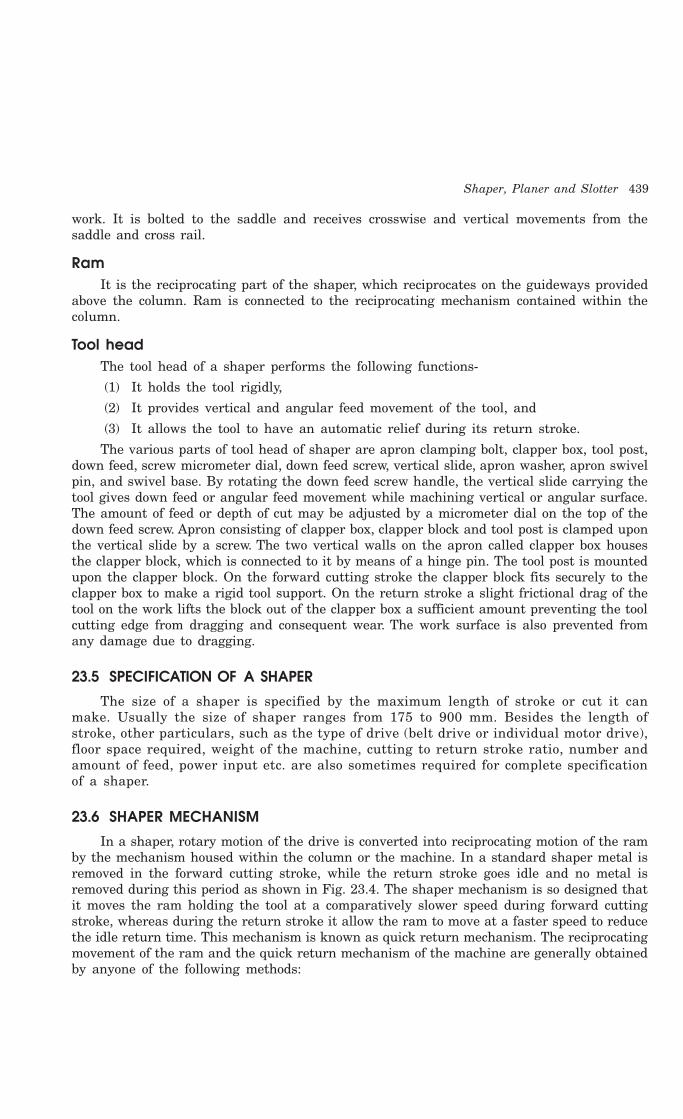
Shaper, Planer and Slotter 439
work. It is bolted to the saddle and receives crosswise and vertical movements from thesaddle and cross rail.
RamIt is the reciprocating part of the shaper, which reciprocates on the guideways provided
above the column. Ram is connected to the reciprocating mechanism contained within thecolumn.
Tool headThe tool head of a shaper performs the following functions-
(1) It holds the tool rigidly,
(2) It provides vertical and angular feed movement of the tool, and
(3) It allows the tool to have an automatic relief during its return stroke.
The various parts of tool head of shaper are apron clamping bolt, clapper box, tool post,down feed, screw micrometer dial, down feed screw, vertical slide, apron washer, apron swivelpin, and swivel base. By rotating the down feed screw handle, the vertical slide carrying thetool gives down feed or angular feed movement while machining vertical or angular surface.The amount of feed or depth of cut may be adjusted by a micrometer dial on the top of thedown feed screw. Apron consisting of clapper box, clapper block and tool post is clamped uponthe vertical slide by a screw. The two vertical walls on the apron called clapper box housesthe clapper block, which is connected to it by means of a hinge pin. The tool post is mountedupon the clapper block. On the forward cutting stroke the clapper block fits securely to theclapper box to make a rigid tool support. On the return stroke a slight frictional drag of thetool on the work lifts the block out of the clapper box a sufficient amount preventing the toolcutting edge from dragging and consequent wear. The work surface is also prevented fromany damage due to dragging.
23.5 SPECIFICATION OF A SHAPER
The size of a shaper is specified by the maximum length of stroke or cut it canmake. Usually the size of shaper ranges from 175 to 900 mm. Besides the length ofstroke, other particulars, such as the type of drive (belt drive or individual motor drive),floor space required, weight of the machine, cutting to return stroke ratio, number andamount of feed, power input etc. are also sometimes required for complete specificationof a shaper.
23.6 SHAPER MECHANISM
In a shaper, rotary motion of the drive is converted into reciprocating motion of the ramby the mechanism housed within the column or the machine. In a standard shaper metal isremoved in the forward cutting stroke, while the return stroke goes idle and no metal isremoved during this period as shown in Fig. 23.4. The shaper mechanism is so designed thatit moves the ram holding the tool at a comparatively slower speed during forward cuttingstroke, whereas during the return stroke it allow the ram to move at a faster speed to reducethe idle return time. This mechanism is known as quick return mechanism. The reciprocatingmovement of the ram and the quick return mechanism of the machine are generally obtainedby anyone of the following methods:

440 Introduction to Basic Manufacturing Processes and Workshop Technology
(1) Crank and slotted link mechanism(2) Whitworth quick return mechanism, and(2) Hydraulic shaper mechanism
The crank and slotted link mechanism is discussed as under.
23.6.1 Crank and Slotted Link MechanismIn crank and slotted link mechanism (Fig. 23.6), the pinion receives its motion from an
individual motor or overhead line shaft and transmits the motion or power to the bull gear.Bull gear is a large gear mounted within the column. Speed of the bull gear may be changedby different combination of gearing or by simply shifting the belt on the step cone pulley. Aradial slide is bolted to the centre of the bull gear. This radial slide carries a sliding blockinto which the crank pin is fitted. Rotation of the bull gear will cause the bush pin to revolveat a uniform speed. Sliding block, which is mounted upon the crank pin is fitted within theslotted link. This slotted link is also known as the rocker arm. It is pivoted at its bottom endattached to the frame of the column. The upper end of the rocker arm is forked and connectedto the ram block by a pin. With the rotation of bull gear, crank pin will rotate on the crankpin circle, and simultaneously move up and down the slot in the slotted link giving it arocking movement, which is communicated to the ram. Thus the rotary motion of the bullgear is converted to reciprocating motion of the ram.
Down feed
Head
C lapper box
Bu ll whee l path
Block
V ibrating a rm
Ram L inkage
Ram position ing screw
Ram position ing c lam p
Length o f s troke
Length o f s troke adjustm ent
H inge p in
—35
—25
(a) (b )
Fig. 23.6 Crank and slotted link mechanism
23.7 SURFACES PRODUCED ON SHAPER
1. Horizontal plain surface
2. Vertical plain surface
3. Inclined surface
4. Grooved surface
5. Slotted surface
6. Stepped surface
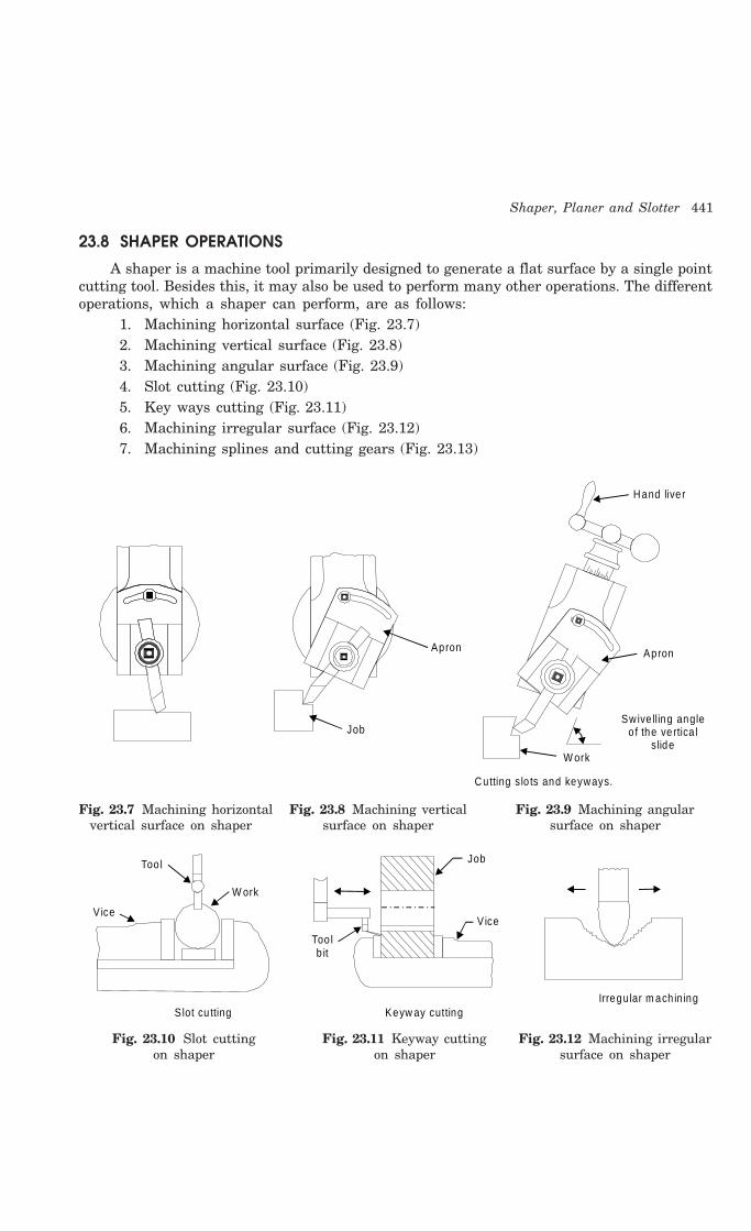
Shaper, Planer and Slotter 441
23.8 SHAPER OPERATIONS
A shaper is a machine tool primarily designed to generate a flat surface by a single pointcutting tool. Besides this, it may also be used to perform many other operations. The differentoperations, which a shaper can perform, are as follows:
1. Machining horizontal surface (Fig. 23.7)2. Machining vertical surface (Fig. 23.8)3. Machining angular surface (Fig. 23.9)4. Slot cutting (Fig. 23.10)5. Key ways cutting (Fig. 23.11)6. Machining irregular surface (Fig. 23.12)7. Machining splines and cutting gears (Fig. 23.13)
Apron
Job
Apron
Sw ive lling angle o f the vertica l
s lideW ork
Cutting s lo ts and keyways.
Hand live r
Fig. 23.7 Machining horizontal Fig. 23.8 Machining vertical Fig. 23.9 Machining angularvertical surface on shaper surface on shaper surface on shaper
Irregular m ach in ing
W ork
Slot cu tting
Too l
V ice
Too l b it
Keyw ay cutting
V ice
Job
Fig. 23.10 Slot cutting Fig. 23.11 Keyway cutting Fig. 23.12 Machining irregularon shaper on shaper surface on shaper
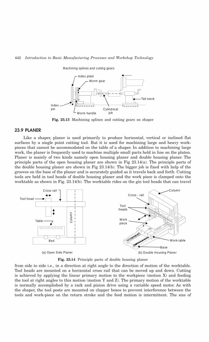
442 Introduction to Basic Manufacturing Processes and Workshop Technology
M ach ining splines and cutting gears
Index plate
W orm gear
Cylindricaljob
Tail s tock
W orm hand le
Index p in
Fig. 23.13 Machining splines and cutting gears on shaper
23.9 PLANER
Like a shaper, planer is used primarily to produce horizontal, vertical or inclined flatsurfaces by a single point cutting tool. But it is used for machining large and heavy work-pieces that cannot be accommodated on the table of a shaper. In addition to machining largework, the planer is frequently used to machine multiple small parts held in line on the platen.Planer is mainly of two kinds namely open housing planer and double housing planer. Theprinciple parts of the open housing planer are shown in Fig 23.14(a). The principle parts ofthe double housing planer are shown in Fig 23.14(b). The bigger job is fixed with help of thegrooves on the base of the planer and is accurately guided as it travels back and forth. Cuttingtools are held in tool heads of double housing planer and the work piece is clamped onto theworktable as shown in Fig. 23.14(b). The worktable rides on the gin tool heads that can travel
Cross - rail
Too l heads
W ork p iece
Co lumn
W ork-tab le
Base
(b) Doub le Housing P laner
Col
umn
Too l head
Tab le
Bed
Cross ra il
(a ) O pen S ide P laner
Fig. 23.14 Principle parts of double housing planer
from side to side i.e., in a direction at right angle to the direction of motion of the worktable.Tool heads are mounted on a horizontal cross rail that can be moved up and down. Cuttingis achieved by applying the linear primary motion to the workpiece (motion X) and feedingthe tool at right angles to this motion (motion Y and Z). The primary motion of the worktableis normally accomplished by a rack and pinion drive using a variable speed motor. As withthe shaper, the tool posts are mounted on clapper boxes to prevent interference between thetools and work-piece on the return stroke and the feed motion is intermittent. The size of

Shaper, Planer and Slotter 443
a standard planer is specified by the size of the largest solid that can reciprocate under thetool. In addition to this, some other parameters such as table size (length and width), typeof drive, number of speeds and feeds available, power input, weight of the machine, floorspace required etc. may be required to specify a planer completely.
23.10 WORKING PRINCIPAL OF PLANER
Fig. 23.15 depicts the workingprinciple of a planer. In a planer, thework which is supported on the tablereciprocates past the stationary cuttingtool and the feed is imparted by thelateral movement of the tool. The toolis clamped in the tool holder and workon the table. Like shaper, the planneris equipped with clapper box to raisethe tool in idle stroke. The differentmechanisms used to give reciprocatingmotion to the table are following-
1. Reversible motor drive2. Open and cross belt drive3. Hydraulic drive
23.11 DIFFERENCE BETWEEN SHAPER AND PLANER
The difference between shaper and planner is given in Table 23.1.
Table 23.1 Difference between Shaper and Planer
S.No. Shaper Planer
1 The work is held stationary and the In a planer, the tool is stationary and thecutting tool on the ram is moved workpiece travels back and forth underback and forth across the work the tool.
2 It is used for shaping much smaller A planer is meant for much larger jobsjobs than can be undertaken on a shaper. Jobs
as large as 6 metre wide and twice aslong can be machined on a planer
3 A shaper is a light machine It is a heavy duty machine.
4 Shaper can employ light cuts and Planer can employ heavier cuts andfiner feed coarse feed,
5 A shaper uses one cutting tool Several tools can cut simultaneously on aat a time planer
6 The shaper is driven using quick- The drive on the planer table is either byreturn link mechanism gears or by hydraulic means
7 It is less rigid and less robust Because of better rigidity of planer, ascompared to that of a shaper, planer cangive more accuracy on machined surfaces.
Too l fixed intool head
W ork p iece reciprocates
M otion o f thework piece
Fig. 23.15 Working principle of a planer
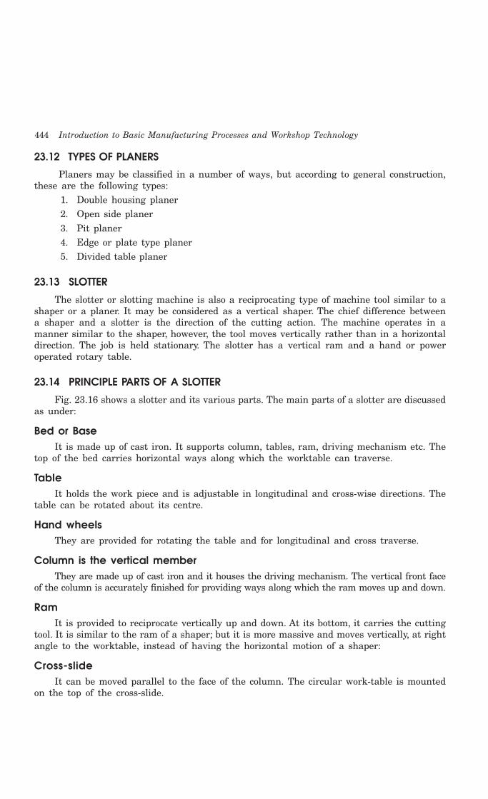
444 Introduction to Basic Manufacturing Processes and Workshop Technology
23.12 TYPES OF PLANERS
Planers may be classified in a number of ways, but according to general construction,these are the following types:
1. Double housing planer2. Open side planer3. Pit planer4. Edge or plate type planer5. Divided table planer
23.13 SLOTTER
The slotter or slotting machine is also a reciprocating type of machine tool similar to ashaper or a planer. It may be considered as a vertical shaper. The chief difference betweena shaper and a slotter is the direction of the cutting action. The machine operates in amanner similar to the shaper, however, the tool moves vertically rather than in a horizontaldirection. The job is held stationary. The slotter has a vertical ram and a hand or poweroperated rotary table.
23.14 PRINCIPLE PARTS OF A SLOTTER
Fig. 23.16 shows a slotter and its various parts. The main parts of a slotter are discussedas under:
Bed or BaseIt is made up of cast iron. It supports column, tables, ram, driving mechanism etc. The
top of the bed carries horizontal ways along which the worktable can traverse.
TableIt holds the work piece and is adjustable in longitudinal and cross-wise directions. The
table can be rotated about its centre.
Hand wheelsThey are provided for rotating the table and for longitudinal and cross traverse.
Column is the vertical memberThey are made up of cast iron and it houses the driving mechanism. The vertical front face
of the column is accurately finished for providing ways along which the ram moves up and down.
RamIt is provided to reciprocate vertically up and down. At its bottom, it carries the cutting
tool. It is similar to the ram of a shaper; but it is more massive and moves vertically, at rightangle to the worktable, instead of having the horizontal motion of a shaper:
Cross-slideIt can be moved parallel to the face of the column. The circular work-table is mounted
on the top of the cross-slide.

Shaper, Planer and Slotter 445
Ram Crank d isc
Lever
Bu ll gear
Cone pulley
Too l
Longitud inal handle
Tab le
C ross feed handle
C ircu la r feed
handle Co lumn
Cross s lide
Feed gear
Base
Feed sha ft
Paw l
Fig. 23.16 Slotter and its various parts
23.15 OPERATIONS PERFORMED ON A SLOTTING MACHINE
A slotter is a very economical machine tool when used for certain classes of work givenas under.
(i) It is used for machining vertical surfaces
(ii) It is used angular or inclined surfaces
(iii) It is used It is used to cut slots, splines keyways for both internal and external jobssuch as machining internal and external gears,
(iv) It is used for works as machining concave, circular, semi-circular and convex surfaces
(v) It is used for shaping internal and external forms or profiles
(vi) It is used for machining of shapes which are difficult to produce on shaper
(vii) It is used for internal machining of blind holes
(viii) It is used for machining dies and punches, and
Since a slotter works slowly. It has less use in mass production work. It can be substitutedby the broaching machine.
23.16 QUESTIONS
1. Explain principal parts of a shaper by neat sketch.
2. How can you classify the shapers?

446 Introduction to Basic Manufacturing Processes and Workshop Technology
3. How can you specify a shaper?
4. Explain the principle of quick return motion mechanism of a shaper. What is need of thismechanism?
5. Using neat sketches, describe the various operations that can be carried on shaping machines.
6. Explain various safety precautions associated with shaper.
7. Explain principal parts of a planer by neat sketches.
8. State the working principle of a planer.
9. Using neat sketch show the various parts of a planer.
10. Classify planers? Explain the universal planer.
11. Show by neat sketches various types of planer tools.
12. How table reversal is obtained in a planer?
13. Using neat sketches, describe the various operations that can be carried on planer.
14. Make neat sketch of a slotter. Explain its working with applications.
15. Differentiate between shaper, planer and slotter.
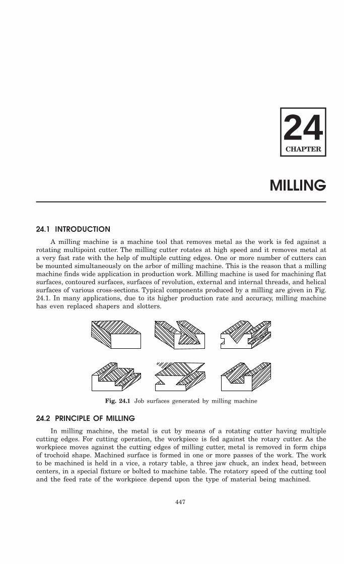
447
MILLING
24.1 INTRODUCTION
A milling machine is a machine tool that removes metal as the work is fed against arotating multipoint cutter. The milling cutter rotates at high speed and it removes metal ata very fast rate with the help of multiple cutting edges. One or more number of cutters canbe mounted simultaneously on the arbor of milling machine. This is the reason that a millingmachine finds wide application in production work. Milling machine is used for machining flatsurfaces, contoured surfaces, surfaces of revolution, external and internal threads, and helicalsurfaces of various cross-sections. Typical components produced by a milling are given in Fig.24.1. In many applications, due to its higher production rate and accuracy, milling machinehas even replaced shapers and slotters.
Fig. 24.1 Job surfaces generated by milling machine
24.2 PRINCIPLE OF MILLING
In milling machine, the metal is cut by means of a rotating cutter having multiplecutting edges. For cutting operation, the workpiece is fed against the rotary cutter. As theworkpiece moves against the cutting edges of milling cutter, metal is removed in form chipsof trochoid shape. Machined surface is formed in one or more passes of the work. The workto be machined is held in a vice, a rotary table, a three jaw chuck, an index head, betweencenters, in a special fixture or bolted to machine table. The rotatory speed of the cutting tooland the feed rate of the workpiece depend upon the type of material being machined.
24CHAPTER

448 Introduction to Basic Manufacturing Processes and Workshop Technology
24.3 MILLING METHODS
There are two distinct methods of milling classified as follows:
1. Up-milling or conventional milling, and
2. Down milling or climb milling.
24.3.1 UP-Milling or Conventional Milling ProcedureIn the up-milling or conventional milling, as shown in Fig. 24.2, the metal is removed
in form of small chips by a cutter rotating against the direction of travel of the workpiece.In this type of milling, the chip thickness is minimum at the start of the cut and maximumat the end of cut. As a result the cutting force also varies from zero to the maximum valueper tooth movement of the milling cutter. The major disadvantages of up-milling process arethe tendency of cutting force to lift the work from the fixtures and poor surface finishobtained. But being a safer process, it is commonly used method of milling.
M illingcutter Depth o f cut
D irection of feed
Job
End of cu t
S tart of cu t
Ch ip cross-section (en la rged)
Fig. 24.2 Principal of up-milling
24.3.2 Down-Milling or Climb MillingDown milling is shown in Fig. 24.3. It is also known as climb milling. In this method,
the metal is removed by a cutter rotating in the same direction of feed of the workpiece. Theeffect of this is that the teeth cut downward instead of upwards. Chip thickness is maximumat the start of the cut and minimum in the end. In this method, it is claimed that there isless friction involved and consequently less heat is generated on the contact surface of thecutter and workpiece. Climb milling can be used advantageously on many kinds of work toincrease the number of pieces per sharpening and to produce a better finish. With climbmilling, saws cut long thin slots more satisfactorily than with standard milling. Anotheradvantage is that slightly lower power consumption is obtainable by climb milling, since thereis no need to drive the table against the cutter.
M illing cutter Depth o f cu t S tart of cu t
End of cu tD irection of feed
Job Chip cross-section (en la rged)
Fig. 24.3 Principal of down-milling

Milling 449
24.4 TYPES OF MILLING CUTTERS
Fig. 24.4 illustrates some types of milling cutters along with workpieces. Milling cuttersare made in various forms to perform certain classes of work, and they may be classified as:
(1) Plain milling cutters,
(2) Side milling cutters,
(3) Face milling cutter,
(4) Angle milling cutters,
(5) End milling cutter,
(6) Fly cutter,
(7) T-slot milling cutter,
(8) Formed cutters,
(9) Metal slitting saw,
Milling cutters may have teeth on the periphery or ends only, or on both the peripheryand ends. Peripheral teeth may be straight or parallel to the cutter axis, or they may behelical, sometimes referred as spiral teeth.
Plain m illing cutter Shell end m ill S ide m illing cu tter
End m ill M etal-slitt ing saw Angle m illing cu tte r Form m illing
Fig. 24.4 Types of milling cutters
24.5 TYPES OF MILLING MACHINES
Milling machine rotates the cutter mounted on the arbor of the machine and at the sametime automatically feed the work in the required direction. The milling machine may beclassified in several forms, but the choice of any particular machine is determined primarilyby the size of the workpiece to be undertaken and operations to be performed. With the abovefunction or requirement in mind, milling machines are made in a variety of types and sizes.According to general design, the distinctive types of milling machines are:
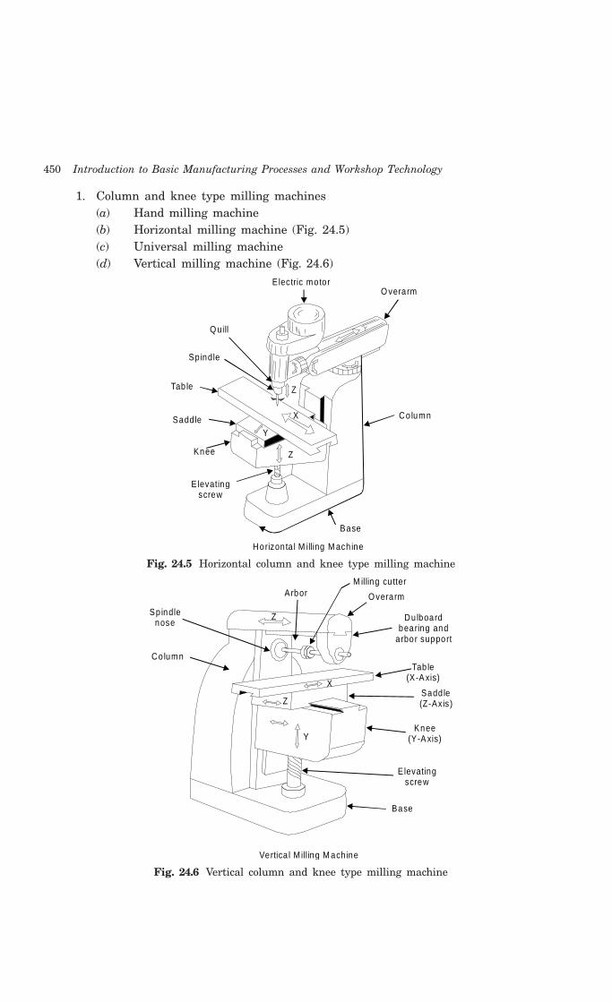
450 Introduction to Basic Manufacturing Processes and Workshop Technology
1. Column and knee type milling machines(a) Hand milling machine(b) Horizontal milling machine (Fig. 24.5)(c) Universal milling machine(d) Vertical milling machine (Fig. 24.6)
Electric motor
Q uill
O verarm
Sp indle
Tab le
Sadd le Co lumnX
Y
Z
Knee
Elevating screw
Base
Horizon ta l M illing M ach ine
Z
Fig. 24.5 Horizontal column and knee type milling machine
Spindle nose
Co lumn
Arbor O verarm
Dulboard bearing and
a rbor support
Tab le (X-A xis)
Sadd le (Z-Axis)
Knee (Y-A xis)
M illing cu tter
E levating screw
Base
Vertica l M illing M ach ine
Y
Z
X
Z
Fig. 24.6 Vertical column and knee type milling machine

Milling 451
2. Planer milling machine3. Fixed-bed type milling machine
(a) Simplex milling machine.(b) Duplex milling machine.(c) Triplex milling machine.
4. Machining center machines5. Special types of milling machines
(a) Rotary table milling machine.(b) Planetary milling machine.(c) Profiling machine.(d) Duplicating machine.(e) Pantograph milling machine.(f) Continuous milling machine.(g) Drum milling machine(h) Profiling and tracer controlled milling machine
Some important types of milling machines are discussed as under.
24.5.1 Column and Knee Type Milling MachineFig. 24.7 shows a simple column and knee type milling machine. It is the most commonly
used milling machine used for general shop work. In this type of milling machine the table
Swive llinghead
Column
Ways
Knee
Base
Screw jack
Sp indle
M illing cu tte r
W ork Tab le
Sadd le
Fig. 24.7 A column and knee type milling machine
452 Introduction to Basic Manufacturing Processes and Workshop Technology
is mounted on the knee casting which in turn is mounted on the vertical slides of the maincolumn. The knee is vertically adjustable on the column so that the table can be moved upand down to accommodate work of various heights. The column and knee type millingmachines are classified on the basis of various methods of supplying power to the table,different movements of the table and different axis of rotation of the main spindle. Columnand knee type milling machine comprises of the following important parts-
1. Base 2. Column3. Saddle 4. Table5. Elevating screw 6. Knee7. Knee elevating handle 8. Cross feed handle9. Front brace 10. Arbor support
11. Arbor 12. Overhanging arm13. Cutter 14. Cone pulley15. Telescopic feed shaft.
The principal parts of a column and knee type milling machine are described as under.
Base
It is a foundation member for all the other parts, which rest upon it. It carries thecolumn at its one end. In some machines, the base is hollow and serves as a reservoir forcutting fluid.
Column
The column is the main supporting member mounted vertically on the base. It is boxshaped, heavily ribbed inside and houses all the driving mechanism for the spindle and tablefeed. The front vertical face of the column is accurately machined and is provided withdovetail guideway for supporting the knee.
Knee
The knee is a rigid grey iron casting which slides up and down on the vertical ways ofthe column face. An elevating screw mounted on the base is used to adjust the height of theknee and it also supports the knee. The knee houses the feed mechanism of the table, anddifferent controls to operate it.
Saddle
The saddle is placed on the top of the knee and it slides on guideways set exactly at 90°to the column face. The top of the saddle provides guide-ways for the table.
Table
The table rests on ways on the saddle and travels longitudinally. A lead screw under thetable engages a nut on the saddle to move the table horizontally by hand or power. Inuniversal machines, the table may also be swiveled horizontally. For this purpose the tableis mounted on a circular base. The top of the table is accurately finished and T -slots areprovided for clamping the work and other fixtures on it
Overhanging arm
It is mounted on the top of the column, which extends beyond the column face and servesas a bearing support for the other end of the arbor.

Milling 453
Front brace
It is an extra support, which is fitted between the knee and the over-arm to ensurefurther rigidity to the arbor and the knee.
Spindle
It is situated in the upper part of the column and receives power from the motor throughbelts, gears. and clutches and transmit it to the arbor.
Arbor
It is like an extension of the machine spindle on which milling cutters are securelymounted and rotated. The arbors are made with taper shanks for proper alignment with themachine spindles having taper holes at their nose. The draw bolt is used for managing forlocking the arbor with the spindle and the whole assembly. The arbor assembly consists ofthe following components.
1. Arbor 2. Spindle
3. Spacing collars 4. Bearing bush
5. Cutter 6. Draw bolt
7. Lock nut 8. Key block
9. Set screw
24.5.2 Planer Type Milling MachineIt is a heavy duty milling machine. It resembles a planer and like a planning machine
it has a cross rail capable of being raised or lowered carrying the cutters, their heads, andthe saddles, all supported by rigid uprights. There may be a number of independent spindlescarrying cutters on the rail as two heads on the uprights. The use of the machine is limitedto production work only and is considered ultimate in metal re-moving capacity.
24.5.3 Special Type Milling Machines Milling machines of non-conventional design have been developed to suit special purposes.
The features that they have in common are the spindle for rotating the cutter and provisionfor moving the tool or the work in different directions.
24.6 SIZE OF MILLING MACHINE
The size of the column and knee type milling machine is specified by
(1) The dimensions of the working surface of the table, and
(2) Its maximum length of longitudinal, cross and vertical travel of the table.
In addition to above, number of spindle speeds, number of feeds, spindle nose taper,power available, floor space required and net weight of machine will also be required foradditional specification.
24.7 DEPTH OF CUT
The depth of cut in milling is defined as the thickness of the material removed in onepass of the work under the cutter. Thus it is the perpendicular distance measured betweenthe original and final surface of the workpiece, and is expressed in mm.

454 Introduction to Basic Manufacturing Processes and Workshop Technology
24.8 INDEXING AND DIVIDING HEADS
Indexing is the operation of dividing the periphery of a piece of work into any numberof equal parts. In cutting spur gear equal spacing of teeth on the gear blank is performed byindexing. Indexing is accomplished by using a special attachment known as dividing head orindex head as shown in Fig. 24.8. The dividing heads are of three types:
(1) Plain or simple dividing head,
(2) Universal dividing head and
(3) Optical dividing head.
Index pin
Index crank
Index p la te
Sector a rm s
W orm
W orm wheel
Sp indle
Face p la te
Centre
Fig. 24.8 Dividing head
24.8.1 Plain or Simple Dividing Head The plain dividing head comprises a cylindrical spindle housed on a frame, and a base
bolted to the machine table. The index crank is connected to the tail end of the spindledirectly, and the crank and the spindle rotate as one unit. The index plate is mounted on thespindle and rotates with it. The spindle may be rotated through the desired angle and thenclamped by inserting the clamping lever pin into anyone of the equally spaced holes or slotscut on the periphery of the index plate. This type of dividing head is used for handling largenumber of workpieces, which require a very small number of divisions on the periphery.
1. Swiveling block 2. Live centre
3. Index crank 4. Index plate.
24.9 OPERATIONS PERFORMED ON MILLING MACHINE
Unlike a lathe, a milling cutter does not give a continuous cut, but begins with a slidingmotion between the cutter and the work. Then follows a crushing movement, and then acutting operation by which the chip is removed. Many different kinds of operations can beperformed on a milling machine but a few of the more common operations will now beexplained. These are:
Plain milling or slab millingFig. 24.9(a) illustrates the plain and slab milling operation. It is a method of producing
a plain, flat, horizontal surface parallel to the axis of rotation of the cutter.
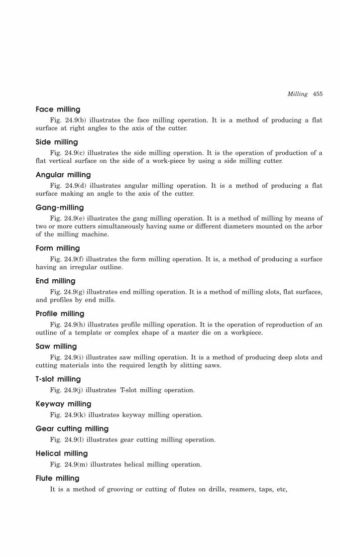
Milling 455
Face millingFig. 24.9(b) illustrates the face milling operation. It is a method of producing a flat
surface at right angles to the axis of the cutter.
Side millingFig. 24.9(c) illustrates the side milling operation. It is the operation of production of a
flat vertical surface on the side of a work-piece by using a side milling cutter.
Angular millingFig. 24.9(d) illustrates angular milling operation. It is a method of producing a flat
surface making an angle to the axis of the cutter.
Gang-millingFig. 24.9(e) illustrates the gang milling operation. It is a method of milling by means of
two or more cutters simultaneously having same or different diameters mounted on the arborof the milling machine.
Form millingFig. 24.9(f) illustrates the form milling operation. It is, a method of producing a surface
having an irregular outline.
End millingFig. 24.9(g) illustrates end milling operation. It is a method of milling slots, flat surfaces,
and profiles by end mills.
Profile millingFig. 24.9(h) illustrates profile milling operation. It is the operation of reproduction of an
outline of a template or complex shape of a master die on a workpiece.
Saw millingFig. 24.9(i) illustrates saw milling operation. It is a method of producing deep slots and
cutting materials into the required length by slitting saws.
T-slot millingFig. 24.9(j) illustrates T-slot milling operation.
Keyway millingFig. 24.9(k) illustrates keyway milling operation.
Gear cutting millingFig. 24.9(l) illustrates gear cutting milling operation.
Helical millingFig. 24.9(m) illustrates helical milling operation.
Flute millingIt is a method of grooving or cutting of flutes on drills, reamers, taps, etc,

456 Introduction to Basic Manufacturing Processes and Workshop Technology
(a ) P lane m illing (b ) Face m illing
End m illing cutter
(g ) End m illing
(c) S ide m illing
(d ) Angu la r m illing (e ) G ang m illing
JobJob
Form m illing cutter
(f) Form M illing
(h ) Pro file m illing
(i) Saw m illing
Job
Saw m illingcutter
1 2
(j) T - S lot M illing
(k) Key way m illing
Job
(l) G ear Cutting M illing

Milling 457
(m ) He lica l m illing
A B
Fig. 24.9 Various types of milling operations
Straddle millingIt is a method of milling two sides of a piece of work by employing two side-milling
cutters at the same time.
Thread millingIt is a method of milling threads on dies, screws, worms, etc. both internally and
externally. As an alternative to the screw cutting in a lathe, this method is being moreextensively introduced now a day in modern machine shops.
24.10 QUESTIONS1. State the working principle of milling machine.
2. How will you classify milling machines?
3. Using neat sketch, describe the principal parts of the milling machine by neat sketches.
4. Differentiate between up milling and down milling.
5. With the help of a neat sketch explain the column and knee type milling machine and nameits main parts.
6. Explain various types of milling operations using neat sketches.
7. Describe thread milling.
8. Sketch and describe the indexing head used for gear cutting.
9. Explain the principle of differential indexing.
10. What is indexing? Describe direct indexing, with example.
11. Single angle milling cutter (b) Slot milling cutter (d) Convex milling cutter.
12. How will you index the gear teeth? Sketch the indexing set-up showing necessary calculations.
13. Sketch the machining set-up indicating tool work motions.
14. Sketch and specify the milling cutter indicating important tool geometry.
15. Define the following terms used in milling operation.
(a) Cutting speed
(b) Feed
(c) Depth of cut
(d) Machining time.

458 Introduction to Basic Manufacturing Processes and Workshop Technology
POWDER METALLURGY
25.1 INTRODUCTION
Powder metallurgy is used for manufacturing products or articles from powdered metalsby placing these powders in molds and are compacting the same using heavy compressiveforce. Typical examples of such article or products are grinding wheels, filament wire, magnets,welding rods, tungsten carbide cutting tools, self-lubricating bearings electrical contacts andturbines blades having high temperature strength. The manufacture of parts by powdermetallurgy process involves the manufacture of powders, blending, compacting, profiteering,sintering and a number of secondary operations such as sizing, coining, machining,impregnation, infiltration, plating, and heat treatment. The compressed articles are thenheated to temperatures much below their melting points to bind the particles together andimprove their strength and other properties. Few non-metallic materials can also be addedto the metallic powders to provide adequate bond or impart some the needed properties. Theproducts made through this process are very costly on account of the high cost of metalpowders as well as of the dies used. The powders of almost all metals and a large quantityof alloys, and nonmetals may be used. The application of powder metallurgy process iseconomically feasible only for high mass production. Parts made by powder metallurgy processexhibit properties, which cannot be produced by conventional methods. Simple shaped partscan be made to size with high precision without waste, and completely or almost ready forinstallation.
25.2 POWDER METALLURGY PROCESS
The powder metallurgy process consists of the following basic steps:
1. Formation of metallic powders.
2. Mixing or blending of the metallic powders in required proportions.
3. Compressing and compacting the powders into desired shapes and sizes in form ofarticles.
4. Sintering the compacted articles in a controlled furnace atmosphere.
5. Subjecting the sintered articles to secondary processing if needed so.
25CHAPTER
458

Powder Metallurgy 459
25.2.1 Production of Metal Powders
Metallic powders possessing different properties can be produced easily. The mostcommonly used powders are copper-base and iron-base materials. But titanium, chromium,nickel, and stainless steel metal powders are also used. In the majority of powders, the sizeof the particle varies from several microns to 0.5 mm. The most common particle size ofpowders falls into a range of 10 to 40 microns. The chemical and physical properties of metalsdepend upon the size and shape of the powder particles. There are various methods ofmanufacturing powders.The commonly used powder making processes are given as under.
1. Atomization
2. Chemical reduction
3. Electrolytic process
4. Crushing
5. Milling
6. Condensation of metal vapors
7. Hydride and carbonyl processes.
The above mentioned metallic powder making techniques are discussed briefly as under.
1. Atomization
In this process, the molten metal is forced through an orifice and as it emerges, a highpressure stream of gas or liquid impinges on it causing it to atomize into fine particles. Theinert gas is then employed in order to improve the purity of the powder. It is used mostlyfor low melting point metals such as tin, zinc, lead, aluminium, cadmium etc., because of thecorrosive action of the metal on the orifice (or nozzle) at high temperatures. Alloy powdersare also produced by this method.
2. Chemical Reduction Process
In this process, the compounds of metals such as iron oxides are reduced with CO or H2at temperatures below the melting point of the metal in an atmosphere controlled furnace.The reduced product is then crushed and ground. Iron powder is produced in this way
Fe3O4 + 4C = 3Fe + 4CO
Fe3O4 + 4CO = 3Fe + 4CO2
Copper powder is also produced by the same procedure by heating copper oxide in astream of hydrogen.
Cu2 + H2 = 2Cu + H2O
Powders of W, Mo, Ni and CO can easily be produced or manufactured by reductionprocess because it is convenient, economical and flexible technique and perhaps the largestvolume of metallurgy powders is made by the process of oxide reduction.
3. Electrolytic Process
Electrolysis process is quite similar to electroplating and is principally employed for theproduction of extremely pure, powders of copper and iron. For making copper powder, copperplates are placed as anodes in a tank of electrolyte, whereas, aluminium plates are placed into the electrolyte to act as cathodes. High amperage produces a powdery deposit of anodemetal on the cathodes. After a definite time period, the cathode plates are taken out from the
460 Introduction to Basic Manufacturing Processes and Workshop Technology
tank, rinsed to remove electrolyte and are then dried. The copper deposited on the cathodeplates is then scraped off and pulverized to produce copper powder of the desired grain size.The electrolytic powder is quite resistant to oxidation.
4. Crushing Process
The crushing process requires equipments such as stamps, crushers or gyratory crushes.Various ferrous and non-ferrous alloys can be heat-treated in order to obtain a sufficientlybrittle material which can be easily crushed into powder form.
5. Milling Process
The milling process is commonly used for production of metallic powder. It is carried outby using equipments such as ball mill, impact mill, eddy mill, disk mill, vortex mill, etc.Milling and grinding process can easily be employed for brittle, tougher, malleable, ductile andharder metals to pulverize them. A ball mill is a horizontal barrel shaped container holdinga quantity of balls, which, being free to tumble about as the container rotates, crush andabrade any powder particles that are introduced into the container. Generally, a large massto be powdered, first of all, goes through heavy crushing machines, then through crushingrolls and finally through a ball mill to produce successively finer grades of powder.
6. Condensation of Metal Powders
This process can be applied in case of metals, such as Zn, Cd and Mg, which can be boiledand the vapors are condensed in a powder form. Generally a rod of metal say Zn is fed intoa high temperature flame and vaporized droplets of metal are then allowed to condense onto a cool surface of a material to which they will not adhere. This method is not highlysuitable for large scale production of powder.
7. Hydride and Carbonyl Processes
High hardness oriented metals such as tantalum, niobium and zirconium are made tocombine with hydrogen form hydrides that are stable at room temperature, but to begin todissociate into hydrogen and the pure metal when heated to about 350°C. Similarly nickel andiron can be made to combine with CO to form volatile carbonyls. The carbonyl vapor is thendecomposed in a cooled chamber so that almost spherical particles of very pure metals aredeposited.
25.2.2 Characteristic of Metal PowdersThe performance of powder metallurgical parts is totally dependent upon the characteristics
of metal powders. Most important characteristics of metal powders are powder particle size,size distribution, particle shape, purity, chemical composition, flow characteristics and particlemicrostructure. Some of the important properties are discussed as under.
Powder particle size and size distribution
Particle size of metal powder is expressed by the diameter for spherical shaped particlesand by the average diameter for non-spherical particle as determined by sieving method ormicroscopic examination. Metal powders used in powder metallurgy usually vary in size from20 to 200 microns. Particle size influences density/porosity of the compact, mold strength,permeability, flow and mixing characteristics, dimensional stability, etc. Particle size distributionis specified in terms of a sieve analysis i.e. the amount of powder passing through 20 or 40mesh sieves.
Powder Metallurgy 461
Particle shape
There are various shapes of metal powders namely spherical, sub-rounded, rounded,angular, sub-angular, flakes etc. Particles shape influences the packing and flow characteristicsof the powders.
Chemical composition
Chemical composition of metallic powder implies the type and percentage of alloyingelements and impurities. It usually determines the particle hardness and compressibility. Thechemical composition of a powder can be determined by chemical analysis methods.
Particle microstructure
Particle microstructure reveals various phases, inclusions and internal porosity.
Apparent density
Apparent density is defined as the weight, of a loosely heated quantity of powder necessaryto fill a given die cavity completely.
Flow characteristics
Flow-ability of metal powders is most important in cases where moulds have to be filledquickly. Metal powders with good flow characteristics fill a mould cavity uniformly.
25.2.3 Mixing or Blending of Metallic PowdersAfter the formation of metallic powders, proper mixing or blending of powders is the
first step in the forming of powder metal parts. The mixing is being carried out either wetor dry using an efficient mixer to produce a homogeneous mixture.
25.2.4 Compacting of Powder
Compacting is the technique of converting loose powder in to compact accurately definedshape and size. This is carried out at room temperature in a die on press machine. The pressused for compacting may be either mechanically or hydraulically operated. The die consistsof a cavity of the shape of the desired part. Metal powder is poured in the die cavity andpressure is applied using punches, which usually work from the top and bottom of the die asshown in Fig 25.1. Dies are usually made of high grade steel, but sometimes carbide dies areused for long production runs. In compacting process, the pressure applied should be uniformand applied simultaneously from above and below. The pressure applied should be highenough to produce cold welding of the powder. Cold welding imparts a green strength, whichholds the parts together and allows them to be handled.
The metal parts obtained after compacting are not strong and dense. To improve theseproperties, the parts should be sintered.
25.2.5 Sintering
Sintering is the process of heating of compacted products in a furnace to below themelting point of at least one of the major constituents under a controlled atmosphere. Thesintering temperature and time vary with the following factors-
1. Type of metal powder
2. Compressive load used, and
3. Strength requirements of the finished parts.

462 Introduction to Basic Manufacturing Processes and Workshop Technology
M etal powder
D ie
Lower punch
Upper punch
D ie cavity Compact
D ie
Fig. 25.1 Powder metallurgy die setup
In the sintering furnace, the metal parts are gradually heated and soaked at the requiredtemperature. During this gradually heating process, powders bond themselves into coherentbodies. Sintering results in strengthening of fragile green compacts produced by the pressingoperation. It also increases electrical conductivity, density and ductility of the powder metalparts.
25.2.6 Secondary OperationsSome powder metal parts may be used in the sintered condition while in some other
cases additional secondary operations have to be performed to get the desired surface finish,close tolerance etc.. The secondary operations may be of following types-
1. Annealing.
2. Repressing for greater density or closer dimensional control.
3. Machining.
4. Polishing.
5. Rolling, forging or drawing.
6. Surface treatments to protect against corrosion.
7. In some cases infiltration is needed to provide increased strength, hardness, densityobtainable by straight sintering.
8. The procedures for plating powdered metal parts are quite different from those usedfor wrought or cast metal parts. In powdered metal parts, porosity must be eliminatedbefore the part is plated. After the porosity has been eliminated regular platingprocedures can be used.
25.3 ADVANTAGES OF POWDER METALLURGY
1. The processes of powder metallurgy are quite and clean.
2. Articles of any intricate or complicated shape can be manufactured.

Powder Metallurgy 463
3. The dimensional accuracy and surface finish obtainable are much better for manyapplications and hence machining can be eliminated.
4. Unlike casting, press forming machining, no material is being wasted as scrap andthe process makes utilizes full raw material
5. Hard to process materials such as diamond can be converted into usable componentsand tools through this process.
6. High production rates can be easily achieved.
7. The phase diagram constraints, which do not allow an alloy formation betweenmutually insoluble constituents in liquid state, such as in case of copper and leadare removed in this process and mixtures of such metal powders can be easilyprocessed and shaped through this process.
8. This process facilitates production of many such parts, which cannot be producedthrough other methods, such as sintered carbides and self-lubricating bearings.
9. The process enables an effective control over several properties such as purity,density, porosity, particle size, etc., in the parts produced through this process.
10. The components produced by this process are highly pure and bears longer life.
11. It enables production of parts from such alloys, which possess poor cast ability.
12. It is possible to ensure uniformity of composition, since exact proportions ofconstituent metal powders can be used.
13. The preparation and processing of powdered iron and nonferrous parts made in thisway exhibit good properties, which cannot be produced in any other way.
14. Simple shaped parts can be made to size with 100 micron accuracy without waste
15. Porous parts can be produced that could not be made in any other way.
16. Parts with wide variations in compositions and materials can be produced.
17. Structure and properties can be controlled more closely than in other fabricatingprocesses.
18. Highly qualified or skilled labor is not required. in powder metallurgy process
19. Super-hard cutting tool bits, which are impossible to produce by other manufacturingprocesses, can be easily manufactured using this process.
20. Components shapes obtained possess excellent reproducibility.
21. Control of grain size, relatively much uniform structure and defect such voids andblowholes in structure can be eliminated.
25.4 LIMITATIONS OF POWDER METALLURGY
1. Powder metallurgy process is not economical for small-scale production.
2. The cost of tool and die of powder metallurgical set-up is relatively high
3. The size of products as compared to casting is limited because of the requirementof large presses and expensive tools which would be required for compacting.
4. Metal powders are expensive and in some cases difficult to store without somedeterioration.

464 Introduction to Basic Manufacturing Processes and Workshop Technology
5. Intricate or complex shapes produced by casting cannot be made by powdermetallurgy because metallic powders lack the ability to flow to the extent of moltenmetals.
6. Articles made by powder metallurgy in most cases do not have as good physicalproperties as wrought or cast parts.
7. It may be difficult sometimes to obtain particular alloy powders
8. Parts pressed from the top tend to be less dense at the bottom.
9. A completely deep structure cannot be produced through this process.
10. The process is not found economical for small-scale production.
11. It is not easy to convert brass, bronze and a numbers of steels into powdered form.
25.5 APPLICATIONS OF POWDER METALLURGY
The powder metallurgy process has provided a practical solution to the problem ofproducing refractory metals, which have now become the basis of making heat-resistantmaterials and cutting tools of extreme hardness. Another very important and useful itemof the products made from powdered metals is porous self-lubricating bearing. In short,modern technology is inconceivable without powder metallurgy products, the various fieldsof application of which expand every year. Some of the powder metal products are given asunder.
1. Porous products such as bearings and filters.
2. Tungsten carbide, gauges, wire drawing dies, wire-guides, stamping and blankingtools, stones, hammers, rock drilling bits, etc.
3. Various machine parts are produced from tungsten powder. Highly heat and wearresistant cutting tools from tungsten carbide powders with titanium carbide, powdersare used for and die manufacturing.
4. Refractory parts such as components made out of tungsten, tantalum andmolybdenum are used in electric bulbs, radio valves, oscillator valves, X-ray tubesin the form of filament, cathode, anode, control grids, electric contact points etc.
5. Products of complex shapes that require considerable machining when made byother processes namely toothed components such as gears.
6. Components used in automotive part assembly such as electrical contacts, crankshaftdrive or camshaft sprocket, piston rings and rocker shaft brackets, door, mechanisms,connecting rods and brake linings, clutch facings, welding rods, etc.
7. Products where the combined properties of two metals or metals and non-metalsare desired such as non-porous bearings, electric motor brushes, etc.
8. Porous metal bearings made which are later impregnated with lubricants. Copperand graphite powders are used for manufacturing automobile parts and brushes.
9. The combinations of metals and ceramics, which are bonded by similar process asmetal powders, are called cermets. They combine in them useful properties of highrefractoriness of ceramics and toughness of metals. They are produced in two formsnamely oxides based and carbide based.

Powder Metallurgy 465
25.6 QUESTIONS1. What do you under stand by powder metallurgy? What are the main stages of powder
metallurgy process?
2. What important considerations should be made in designing the powder metallurgy products?
3. Explain the objectives of powder compaction and list important products of powder metallurgy.
4. Describe briefly the methods by which powders suitable for powder metallurgy can beproduced. Also enumerate the main characteristics of metal powder.
5. Describe the atomization process of making powder in detail.
6. What are the effects of sintering on the powder compact produced by pressing?
7. Describe the process of blending, compacting and sintering in detail.
8. What are the effects of sintering on the powder compact produced by pressing?
9. Name the products of powder metallurgy.
10. List the advantages, dis-advantages and applications of powder metallurgy process.
11. It is necessary to use lubricants in the press compaction of powders? Explain.
12. What are ‘cermets’? Give a few examples of useful applications
13. State briefly the process of making a powder metallurgy product having improved properties.
14. What are cemented carbides? How are they processed?

466 Introduction to Basic Manufacturing Processes and Workshop Technology
INSPECTION AND QUALITY CONTROL
26.1 INTRODUCTION
Inspection or checking of components or products with required specifications is veryminutely related with quality control. It is generally an accepted fact that no two things canever be exactly same. It also holds true with manufactured parts. Therefore certain variationsor deviations in dimensions and other product specifications are accepted. However, only fewproduced articles or parts may be rejected if the deviations go beyond the specified qualitystandards. Therefore it becomes essential to detect errors so that the manufacturing of faultyproduct does not go uncorrected. The philosophy of inspection is only preventive and notremedial. In other words the inspection of products is measuring or checking its quality interms geometrical tolerances of other specified feature of needed design. Generally, there arethree basic areas of inspection namely receiving inspection, in-process inspection and finalinspection. In the receiving inspection, inspections are performed on all incoming materialsand purchased parts. In the in-process inspection the products are inspected as they are inprocessed in stages from starting station to finished station. In the final inspection, allfinished products or parts are inspected finally prior to delivering them to the customer.
The main motive of manufacturing is to process engineering materials and producedesired and useful components or products to the specified shape, size and finish. Thespecifications for the shapes, sizes and finishes on the products are furnished by themanufacturing operations through specified process plan using part drawings or manufacturingdrawings. These specifications basically termed as called quality characteristics. The qualityof manufactured product is depend always upon the process capability of controllingmanufacturing functions which may lead to a certain amount of variation as a result of chanceand some cause. Also some chance or cause is inherent in any particular scheme of productionand inspection. The reasons for variation outside this stable system should be discovered andcorrected to minimize wastage and finally to improve quality.
26.2 TOLERANCES ON PARTS
It is difficult to manufacture any product or component to its exact size. Tolerance onthe parts is therefore the amount of variation in size tolerated to cover reasonable imperfectionsin workmanship and it varies with different grades of work. Tolerance on a dimension canalso be specified as the difference between the maximum limit of size and the minimum limit
26CHAPTER
466
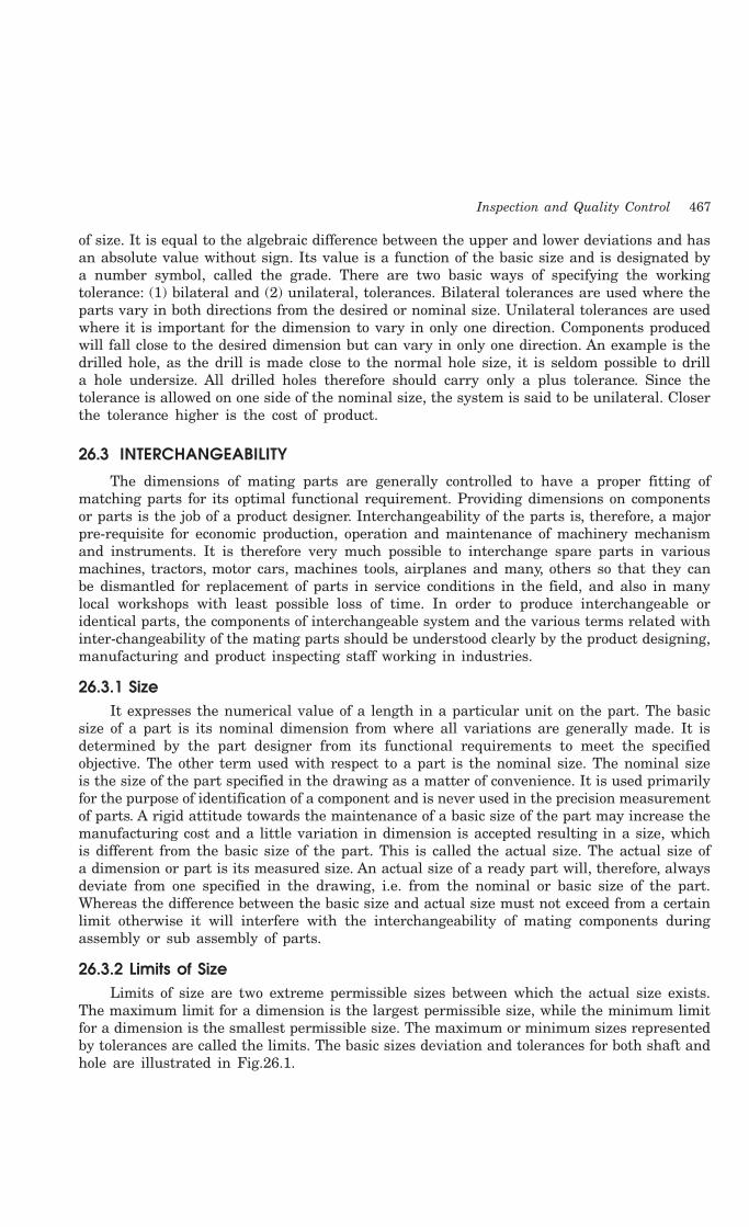
Inspection and Quality Control 467
of size. It is equal to the algebraic difference between the upper and lower deviations and hasan absolute value without sign. Its value is a function of the basic size and is designated bya number symbol, called the grade. There are two basic ways of specifying the workingtolerance: (1) bilateral and (2) unilateral, tolerances. Bilateral tolerances are used where theparts vary in both directions from the desired or nominal size. Unilateral tolerances are usedwhere it is important for the dimension to vary in only one direction. Components producedwill fall close to the desired dimension but can vary in only one direction. An example is thedrilled hole, as the drill is made close to the normal hole size, it is seldom possible to drilla hole undersize. All drilled holes therefore should carry only a plus tolerance. Since thetolerance is allowed on one side of the nominal size, the system is said to be unilateral. Closerthe tolerance higher is the cost of product.
26.3 INTERCHANGEABILITY
The dimensions of mating parts are generally controlled to have a proper fitting ofmatching parts for its optimal functional requirement. Providing dimensions on componentsor parts is the job of a product designer. Interchangeability of the parts is, therefore, a majorpre-requisite for economic production, operation and maintenance of machinery mechanismand instruments. It is therefore very much possible to interchange spare parts in variousmachines, tractors, motor cars, machines tools, airplanes and many, others so that they canbe dismantled for replacement of parts in service conditions in the field, and also in manylocal workshops with least possible loss of time. In order to produce interchangeable oridentical parts, the components of interchangeable system and the various terms related withinter-changeability of the mating parts should be understood clearly by the product designing,manufacturing and product inspecting staff working in industries.
26.3.1 SizeIt expresses the numerical value of a length in a particular unit on the part. The basic
size of a part is its nominal dimension from where all variations are generally made. It isdetermined by the part designer from its functional requirements to meet the specifiedobjective. The other term used with respect to a part is the nominal size. The nominal sizeis the size of the part specified in the drawing as a matter of convenience. It is used primarilyfor the purpose of identification of a component and is never used in the precision measurementof parts. A rigid attitude towards the maintenance of a basic size of the part may increase themanufacturing cost and a little variation in dimension is accepted resulting in a size, whichis different from the basic size of the part. This is called the actual size. The actual size ofa dimension or part is its measured size. An actual size of a ready part will, therefore, alwaysdeviate from one specified in the drawing, i.e. from the nominal or basic size of the part.Whereas the difference between the basic size and actual size must not exceed from a certainlimit otherwise it will interfere with the interchangeability of mating components duringassembly or sub assembly of parts.
26.3.2 Limits of SizeLimits of size are two extreme permissible sizes between which the actual size exists.
The maximum limit for a dimension is the largest permissible size, while the minimum limitfor a dimension is the smallest permissible size. The maximum or minimum sizes representedby tolerances are called the limits. The basic sizes deviation and tolerances for both shaft andhole are illustrated in Fig.26.1.
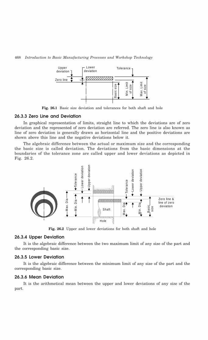
468 Introduction to Basic Manufacturing Processes and Workshop Technology
Zero line
Upper devia tion
Lower devia tion
Tolerance
Bas
ic s
ize
Min
. Lim
it of
siz
e
Max
. Lim
it of
siz
e
Fig. 26.1 Basic size deviation and tolerances for both shaft and hole
26.3.3 Zero Line and DeviationIn graphical representation of limits, straight line to which the deviations are of zero
deviation and the represented of zero deviation are referred. The zero line is also known asline of zero deviation is generally drawn as horizontal line and the positive deviations areshown above this line and the negative deviations below it.
The algebraic difference between the actual or maximum size and the correspondingthe basic size is called deviation. The deviations from the basic dimensions at theboundaries of the tolerance zone are called upper and lower deviations as depicted inFig. 26.2.
Tole
ranc
e
Low
er d
evia
tion
Upp
er d
evia
tion
Tole
ranc
e
Low
er d
evia
tion
Upp
er d
evia
tion
Max
. Dia
Min
. Dia
Max
. Dia
Min
. Dia
Shaft
Ho le
Zero line & line o f zero devia tion
Bas
ic
size
Fig. 26.2 Upper and lower deviations for both shaft and hole
26.3.4 Upper DeviationIt is the algebraic difference between the two maximum limit of any size of the part and
the corresponding basic size.
26.3.5 Lower DeviationIt is the algebraic difference between the minimum limit of any size of the part and the
corresponding basic size.
26.3.6 Mean DeviationIt is the arithmetical mean between the upper and lower deviations of any size of the
part.
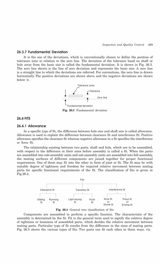
Inspection and Quality Control 469
26.3.7 Fundamental DeviationIt is the one of the deviations, which is conventionally chosen to define the position of
tolerance zone in relation to the zero line. The deviation of the tolerance band on shaft orhole away from the basic size is called the fundamental deviation. It is shown in Fig. 26.3.The zero line shown is the line of zero deviation and represents the basic size. A zero lineis a straight line to which the deviations are referred. For conventions, the zero line is drawnhorizontally. The positive deviations are shown above and the negative deviations are shownbelow it.
Fundam ental deviation
Tolerance zone
Tolerance
Zero line
Fig. 26.3 Fundamental deviation
26.4 FITS
26.4.1 AllowanceIn a specific type of fit, the difference between hole size and shaft size is called allowance.
Allowance is used to explain the difference between clearance fit and interference fit. Positiveallowance specifies the clearance fit whereas negative allowance in a fit specifies the interferenceor force fit.
The relationship existing between two parts, shaft and hole, which are to be assembled,with respect to the difference in their sizes before assembly is called a fit. When the partsare assembled into sub-assembly units and sub assembly units are assembled into full assembly,the mating surfaces of different components are joined together for proper functionalrequirement. One of them may fit into the other in form of joint or fit. The fit may be withsuitable degree of tightness and freedom for required relative movement between matingparts for specific functional requirements of the fit. The classification of fits is given inFig.26.4.
Clearance fit Transition fit In te rfe rence fit
S lid ing fit
Runn ingfit
Push fit
L igh t keying fit
Press fit o r
D riving fit
fo rce fit o r
Shrink fit
F its
Fig. 26.4 General tree classification of fits
Components are assembled to perform a specific function. The characteristic of theassembly is determined by the fit. Fit is the general term used to signify the relative degreeof tightness or looseness of assembled parts, which decides the relative movement betweenmating parts. Particular type of fit results from the difference in the sizes of mating parts.Fig. 26.5 shows the various types of fits. Two parts can fit each other in three ways, viz.

470 Introduction to Basic Manufacturing Processes and Workshop Technology
1. Clearance fit
2. Interference fit
3. Transition fit.
Basic s ize
Ho le ShaftH igh lim it
Shaft
Shaft
In te rference fit
C learance fit
Low lim it
Transition fit
Fig. 26.5 Graphical representation of types of fits
26.4.2 Clearance FitClearance fit is one in which two assembled parts are always free to move relative to
each other in the assembly. In the clearance fit, the largest permitted shaft diameter issmaller than the diameter of the smallest hole. The difference between the size of hole andthe size of shaft is defined as clearance. Clearance fits have limits of size prescribed so thata clearance always results in a positive allowance, or air space is left between mating parts.The parts can be assembled by hand. Clearance fit is of two kinds namely sliding and runningfits. Examples of clearance fit are door hinges, wheel and axle, shaft and bearing, etc. usedin the assembly of parts.
26.4.3 Interference FitIn the interference fit, mating parts in sub assembly or main assembly are joined tightly
together and no relative motion is possible. The minimum permitted diameter of the shaftis larger than the maximum allowable diameter of the hole. In this case, the shaft and thehole member in any sub assembly or main assembly is to be attached permanently and usedas a solid component but according to the application of this combination, this type of fit canbe varied. Interference fit is used for permanent or semi-permanent assembly of parts, whichrequire rigidity and alignment and no relative motion, such as dowel pins and bearings incasting. The difference between the size of shaft and the size of hole in anysub assembly ormain assembly is called interference or negative clearance or negative allowance. Interferencefit has limits of size so prescribed that interference always results when mating parts areassembled. Transition fits is of two kinds namely driving or press fit and shrink or force fit.To assemble, parts are usually pressed together using an arbor press.
26.4.4 Transition FitIn this type of fit, the diameter of the largest allowable hole is greater than that of the
smallest shaft, but the smallest hole is smaller than the largest shaft, so that small positiveor negative clearance between the shaft and hole member is employable. Thus, transition fithas limits of size of hole and shaft such that either a clearance or an interference fit mayresult when two specific parts from the lot are assembled. Here the tolerance zones of thehole and shaft overlap. Transition fits are a compromise between clearance and interference
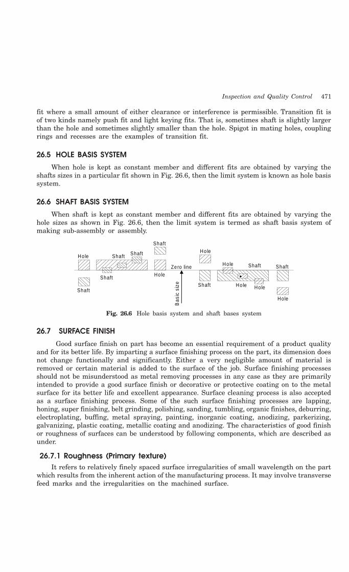
Inspection and Quality Control 471
fit where a small amount of either clearance or interference is permissible. Transition fit isof two kinds namely push fit and light keying fits. That is, sometimes shaft is slightly largerthan the hole and sometimes slightly smaller than the hole. Spigot in mating holes, couplingrings and recesses are the examples of transition fit.
26.5 HOLE BASIS SYSTEM
When hole is kept as constant member and different fits are obtained by varying theshafts sizes in a particular fit shown in Fig. 26.6, then the limit system is known as hole basissystem.
26.6 SHAFT BASIS SYSTEM
When shaft is kept as constant member and different fits are obtained by varying thehole sizes as shown in Fig. 26.6, then the limit system is termed as shaft basis system ofmaking sub-assembly or assembly.
Hole
Shaft
Bas
ic s
ize
Ze ro line Ho le Shaft
Shaft
Shaft Ho le
Ho le
Ho le Ho le
Ho le
Shaft
Shaft Shaft
Shaft
Fig. 26.6 Hole basis system and shaft bases system
26.7 SURFACE FINISH
Good surface finish on part has become an essential requirement of a product qualityand for its better life. By imparting a surface finishing process on the part, its dimension doesnot change functionally and significantly. Either a very negligible amount of material isremoved or certain material is added to the surface of the job. Surface finishing processesshould not be misunderstood as metal removing processes in any case as they are primarilyintended to provide a good surface finish or decorative or protective coating on to the metalsurface for its better life and excellent appearance. Surface cleaning process is also acceptedas a surface finishing process. Some of the such surface finishing processes are lapping,honing, super finishing, belt grinding, polishing, sanding, tumbling, organic finishes, deburring,electroplating, buffing, metal spraying, painting, inorganic coating, anodizing, parkerizing,galvanizing, plastic coating, metallic coating and anodizing. The characteristics of good finishor roughness of surfaces can be understood by following components, which are described asunder.
26.7.1 Roughness (Primary texture)It refers to relatively finely spaced surface irregularities of small wavelength on the part
which results from the inherent action of the manufacturing process. It may involve transversefeed marks and the irregularities on the machined surface.
472 Introduction to Basic Manufacturing Processes and Workshop Technology
26.7.2 Waviness (Secondary texture)It consists of those surface irregularities on the part, which are of considerable wavelength
of a periodic character. It may be caused by vibrations, machine or work deflection, chatter,wrapping, etc. It appears in machining operations such as turning, milling, planning shaping,broaching and grinding.
26.7.3 ProfileIt is defined as the contour of any section through a surface on the part.
26.7.4 LayIt is defined as the direction of the predominant surface pattern on the part. It is
ordinarily determined by the method used in the production of the article.
26.7.5 FlawsThese are surface imperfections such as minute cavities, holes, porosities, cracks, etc.
which appear at frequent intervals and at random locations. The flaws should not be availableon the surface.
Some of the well recognized methods for evaluating the roughness of a surface on theparts are centre line average (CLA) method, envelope method and root mean square (RMS)method.
26.8 QUALITY CONTROL
The term quality of product in production processes implies the best for the moneyinvested and does not necessarily mean the best. Therefore quality of the product is therelative term and generally explained with reference to the end use of a product. A productcan be referred to be of good quality if it works very well and perform good function in aparticular situation for which it is meant or designed while in other situation it may not workwell and it is said to be of bad quality. The word control means regulation, which furtherimplies observations and manipulation. It suggests when to inspect, how often to inspect andhow much to inspect. The basic philosophy of quality control is both preventive and remedial.Quality control strategy sometime identifies the important check measures and implementsthem to check so that the defective items are not produced at all. When rejection of productsis increasing, some immediate corrective action should be evolved and taken suitably toprevent further recurrence of product rejection of parts. Therefore well-planned inspectionwill act to be an important tool of controlling quality of products. It checks the products atspecified stages while quality control attempts to bring the variable factors of manufacturingunder control for achieving the total product specification for meeting customary demands tothe maximum possible extent.
26.8.1 Stastical Quality ControlFull inspection of the finished product by usual inspection devices is time consuming and
costly. Also in a continuous production process 100% inspection may not be found practicable.Certain statistical techniques have been formulated to evaluate materials, processes andproducts by observing capabilities and trends in variations so that continual analysis predictionsmay be made to control the desired quality level of the part. These statistical techniques arecalled statistical quality control techniques. These techniques are

Inspection and Quality Control 473
1. Control charts for measurable quality characteristics. These are described ascharts for variables, or as charts for X and R (average and range) and charts foraverage and standard deviation.
2. Control chart for fraction defective. This is described as the p chart.
3. Control chart for number of defects per unit. This is described as p chart.
26.8.2 Control ChartsControl charts are commonly used in quality control in industries to maintain a continuous
evaluation of the manufacturing process. Control chart is simply a frequency distribution ofthe observed values plotted as points in order of occurrence so that each value has its ownidentity relative to the time of observation. Points on the control charts may or may not beconnected. The chart is provided with limit lines, called control limits, having, in general, oneupper control limit and one lower control limit. A process is said to be in control if theobserved values are influenced only by chance causes fall within the limits and out of controlwhen assignable causes seem to be operating in the system and the observed value falloutside the limits. It is important that the control limits of the control charts do not representthe performance limit or limits of the manufacturing process nor do these represent thespecification limits of the manufacturing drawing of the part. The performance limits of themanufacturing process of the part are the limiting dimensions within which practically allparts fall. If the distribution is normal or near normal, there are three sigma limits of thetotal distribution in both side and three sigma limits forms the basis of quality control.However, points which fall outside of the control limits do not represent rejected item onlysignal that some corrective action is essential to check the manufacturing function and hencemay lead to control the whole processing process for avoiding wastage involved in rejectionof the items.
26.9 ISO 9000
ISO is the International Organization for Standardization based in Geneva, Switzerland.It was founded in 1947 for the purpose of advancing standardization around the world andsetting up standards for achieving and maintaining quality. This non-governmental organizationnow comprises over 130 member countries. Each country is represented by its respectivenational standards body (for India, it is Bureau of Indian Standards) and participates indeveloping standards to facilitate trade of goods and services in the global marketplace. Thestandards developed apply not only to the economic related activities but also cover therelated technology and science involved in these pursuits.
ISO 9000 series of internationally recognized quality management standards representsthe essential requirements that every enterprise needs to address to ensure the consistentproduction and timely delivery of its goods and services to the marketplace. Their genericnature allows for their application to any type of organization. Consistency in production andreliability in delivery are as important as what an organization is selling in today’s marketplace.It is essential to meet consistently all of the customer’s expectations all the time and everytime, to keep them satisfied and loyal.
The ISO 9000 series is able to provide these quality management benefits to organizationsof any size, public or private, without dictating how the organization is to be run. Certificationto an internationally recognized quality management standard like one from the ISO 9000series is becoming an important part of distinguishing an organization from its competitors.
474 Introduction to Basic Manufacturing Processes and Workshop Technology
ISO 9000 is becoming popular because it controls quality and saves money too. A companymay decide to use ISO 9000 for many reasons. To develop the system one has to start withgap analysis. A gap analysis will help the enterprise to identify the gaps that exist betweenthe ISO 9000 standard and current processes and will tell exactly what one needs to do tomeet the ISO 9000 quality management standard. An enterprise may chose to follow this pathbecause it needs to control or improves the quality of products and services or to reduce thecosts associated with quality or to become more competitive. Alternatively, an enterprise maychoose this simply because its customers expect it to do so or because a governmental bodyhas made it mandatory.
26.10QUESTIONS1. What is the importance of interchangeability in fitting of mating parts?
2. Define the terms: tolerance, allowance, interference and clearance in fits.
3. Illustrate the unilateral tolerance with figures. How is the tolerance specified?
4. Which points you will keep in mind in selecting the tolerance between the piston and cylinderof an engine?
5. Write short notes on the following:
(i) Nominal size (ii) Basic size (iii) Tolerance (iv) Allowance, (v) Hole Basis System and(vi) Shaft basis system.
6. Write short note on unilateral system of tolerances covering the points-definition, applicationand advantages over die bilateral system.
7. Describe any system of setting limits and fits.
8. State the importance of limits and fits in production of articles.
9. Give the classifications of fits between the mating parts. What type of fit you will requirebetween the piston rod and stuffing box.
10. Describes the various types of fits.
INDEX
475
A
A feeler gauge 381
Abrasives 41
Accidents 26-38, 44, 45, 47, 49, 50
Accidents in industries 30
Acid pickling 298
Additions in polymer 98
Additives 208-212, 214, 220, 223, 228, 230,236, 238
Adhesives 159, 160
Adjustable frame hacksaw 392
Adjustable gap gauge 381
Admiralty brass 81
Admiralty gun metal 90, 91
Advantages of continuous casting 251, 295
Advantages of die casting over sand casting247
Advantages of forging 261, 267, 268
Advantages of powder metallurgy 462
Advantages of resistance welding 333
Age hardening 151
Air furnace 102, 112, 113
Air seasoning 156
Allotropy of iron 131
Allowance 469, 470, 474
Alloy cast iron 53, 54, 58
Alloy steel 52, 53, 64, 66, 68, 73, 75
Alloying elements in steel 65
Alpha iron 132, 136
Aluminium 76-80, 85, 89, 92, 93, 99, 100, 101
Aluminium alloy 77, 101, 187
Aluminium bronze 85
Annealing 130, 138, 139, 140, 142, 150
Annealing and normalizing 139
Antioch process 237
Anvil 269, 270, 272, 273, 274, 275, 280, 281
Application of heat and solder 344
Applications of continuous casting 252
Applications of cupola 108
Applications of cyaniding 147
Applications of different plain carbon steels75
Applications of forging 260, 261
Applications of powder metallurgy 464, 465
Applications of rolling 288
Applications of spot welding 330
Arbor 447, 449, 452, 453, 455
Arc welding equipment 318, 327
Arc welding equipment, setup and related tools318
Arc welding equipments 327
Arc welding machines 325, 327, 328

476 Introduction to Basic Manufacturing Processes and Workshop Technology
Arc welding processes 310, 317
Atomic hydrogen welding 311, 317, 346
Atomization 459, 465
Auger 165, 172, 173
Aus-tempering 144, 145, 151
Austenite 132-136, 138, 140-143, 147
Austenitic stainless steel 70, 71
Automatic guards 36, 37
Automation 2, 3, 7, 8, 9, 15, 16
Availability of steel in market 72
Axe 165, 172
B
Bainite 142, 143, 144, 145
Bakelite 96, 97
Band saw 176, 177, 178
Basic principle of arc welding 317
Batch production 3, 12
Batch furnaces 131
Bauxite 76, 77
Bearing or antifriction alloys 76, 90
Bed of high precision lathe 101
Bell metal 85
Bellows 202
Bench drilling machine 388
Bench lathe 406, 407
Bending 267, 272, 273, 296, 300, 301, 305
Beryllium bronze 84
Bessemer’s matte 86
Bevel gauge 162, 163, 377
Beveled edge firmer chisel 170
Bever protractor 368
Bick iron 352
Binder 208, 209, 210, 213, 220, 221, 223, 228,229, 230, 231, 234, 236, 238, 240
Black heart malleable iron casting 58
Blanking 296, 299, 300, 348, 359, 363
Blast furnace 102, 103, 104, 114
Blending 458, 461, 465
Blending of metallic powders 461
Boring 406, 415, 422, 430, 431, 433
Boring tool 165, 172, 178, 430, 433
Box or batch type furnaces 264
Brass and bronze pattern 182
Brasses 80, 83, 101
Braze welding 311, 321, 342, 347
Brazing 310, 311, 312, 321, 341, 342, 347
Brittleness 119, 120, 129
Broaching machine 445
Bronzes 80, 83, 84, 101
Built-up edge 402, 404
Bulk modulus 120, 125
Butt weld joint 308
C
CAD 8, 9, 12, 13, 15, 16
CAD/CAM 8, 13, 15
Calipers 365, 375
CAM 8, 9, 12, 13, 14, 15, 16
Capstan and turret lathe 408
Carbides 92, 93
Carbon arc welding 310, 317, 321, 346
Carbon tool steel 64, 71, 75
Carbon-dioxide gas molding 234
Carburizing welding flame 313
Carning or C process 248
Carpenter vice 164, 165
Carpentry 152, 153, 154, 159, 162, 163, 164,165, 167, 171, 173, 174, 176, 177, 178
Carpentry machines 176
Carpentry shop 152, 153, 159, 162, 163, 165,171, 173, 174, 177, 178
Carpentry tools 178
Carriage 407-411, 413, 418, 419, 421
Index 477
Cartridge brass 81
Case hardening 137, 145, 147, 149, 151
Case hardening processes 151
Cast iron 52-59, 62, 63, 75
Cast iron castings 57
Cast iron patterns 181
Ccasting 179-184, 186-195, 241-259
Casting defects 241, 243, 252, 253, 258, 259
Casting techniques 241, 248
Causes of accidents 32, 33, 34, 45
Cemented carbides 92
Cementite 131-133, 135, 136, 138, 139, 142,143
Central lathe 407-410, 421
Centre punch 365, 368
Centrifugal casting 249, 250, 251, 258
Centrifugal casting processes 249
Centrifuging casting 251, 252, 258
Centrifuging casting setup 251, 252
Ceramics materials 93
Ceramics tool 92
Cermets 464, 465
Chaplets 192, 196, 225, 239
Characteristic of metal powders 460
Characteristics of a good timber 158, 178
Characteristics of cold working 293
Characteristics of forged parts 269
Charging of cupola furnace 108
Charpy test 126, 127
Checkers 110
Chemical composition of white cast iron 56
Chemical properties 116, 117, 129
Chief alloying elements 65
Chills 196, 226, 239
Chip breaker 402, 405
Chipping hammer 321
Chisel 165, 166, 169, 170, 366, 388, 394, 396
Choice of materials 128
Chucks 411, 412
CIM 2, 9, 11, 13, 15, 16
CIM technologies 13
Circular saw 176, 177, 178
Clamp 160, 165
Clamping divices 384
Clamping tools 193
Clapper box 435, 437, 439, 442, 443
Classification of files 384, 386, 387
Flassification of fits 469
Classification of hot working processes 285
Classification of molding processes 232
Classification of moulding machines 205
Classification of welding and allied processes310
Claw hammer 174
Clay content test 215
Clearance fit 469, 470
Closed molding boxes 203
Cluster mill 287
CNC 2, 4, 9, 14
Coatings 395
Coining process 304
Cold chamber casting machine 246
Cold chamber die casting 244, 246, 257
Cold drawing 301, 302, 304
Cold extrusion 297, 304
Cold pressure welding 311, 333, 338
Cold working 293-296, 299, 304, 305
Cold working process 294-297, 305
Collapsibility 211, 214, 229, 234
Column 450-453, 457
Column and knee type milling machine 450,451, 452, 453, 457
Combination layout 23
Combination set 162, 163, 365, 378, 379

478 Introduction to Basic Manufacturing Processes and Workshop Technology
Combustion zone 107
Combustion zone of cupola 107
Commercially available adhesives 160
Common binders 229
Common hand reamer 389
Common kinds of sheet metal bends 301
Common objectives of risers 239
Common parts of outside micrometer 373
Common pattern materials 180
Common sources of accidents 34
Common timbers, their qualities and uses 153
Common types of chips 402, 403
Ccommon welding joints 306, 307
Common wood joints 175
Commonly used cutting 353, 354
Commonly used files 385
Commonly used measuring tools 354
Commutators of DC generator 328
Compacting of powder 461
Comparison between thermo plastic andthermosetting 97
Comparison of hot working with cold working295
Compass saw 167
Composites 76, 94
Composition and applications of few typicalmaterial 93
Compositions 56
Compositions of ductile cast iron 56
Compound 410, 416, 417
Compound rest 410, 416, 417
Compression 217, 218, 234
Compression test 124, 125
Computer applications in manufacturing 14
Computers in manufacturing 12
Considerations for desiging riser 227
Constanta 86
Constantan 86
Constituents of an oil paint 161
Constituents of iron and steel 131, 133
Constituents of molding sand 209, 238
Constituents of the core sand 229
Construction 106, 112, 114, 115
Construction of drilling machine 422, 423
Construction of lathe machine 408
Construction of the molding box 203
Construction of the outside micrometer 373
Continnous casting 251
Continuous rolling mill 288
Control charts 473
Control of heating devices 266
Conversion 154, 155, 157, 178
Coolents or cutting fluids 403
Ccooling of austenite 140, 141
Cope (flask) 221
Copper 76-80, 83-89, 93, 100, 101
Copper alloys 80
Copper ores 79
Copper-aluminium alloy 78
Core 208-214, 218, 219, 222, 224, 225, 228-235, 240
Core and core box 189
Core baking 230, 231, 235
Core box 183, 189, 190, 191, 193, 196
Core box allowances 191
Core box making tools 192
Core drilling 432
Core finishing 230, 231, 240
Core making 210, 229, 230, 231, 240
Core making machines 230
Core making shop 193
Core ovens 231
Core prints 179, 187, 191, 192, 194, 195, 229,240
Core sand 208-214, 218, 219, 224, 228-232,240
Index 479
Core sand preparation 230
Coreless type induction furnace 112
Core-making 240
Counter-boring 430, 431
Counter-sinking 430, 431
Crank and slotted link mechanism 440
Crank shaper 436
Creep 121, 123, 128, 129
Critical temperatures 136
Cr-Mo-steel 73
Cross rail of shaper 438
Crosscut saw 167
Crucible 103, 111, 112, 114, 197, 202, 203,204, 206
Cupola furnace 102, 103, 105, 107, 109, 110,114
Cupola furnace 105, 106, 109
Cutting edge 398, 399, 400, 401, 402
Cutting gears on shaper 442
Cutting speed 420, 421, 433
Cutting tools 162, 165, 178, 349, 353, 364,366, 384, 387, 396, 397-405
Cyaniding 137, 145, 147, 149, 150, 151
D
De Levaud casting process 250
Dead carbon steel 53, 62
Defects due to abnormal growth of trees 157
Defects due to conversion and seasoning 157
Defects due to fungi and insects 158
Defects in forged parts 278
Defects in forging 279, 281
Defects in timber 157, 178
Delta metal 82
Demerits of hot working 285
Depth micrometer 372, 374
Design considerations in pattern making 194
Design principles for drop forging 278
Designation of steel 64, 73, 75
Destructive and non-destructive testingmethods 259
Destructive tests 123
Dextrin 210, 211, 229, 231, 234
Dial indicators 377
Diamond 92, 93
Die casting 242, 244, 245, 246, 247, 257
Die casting machine 244, 245, 246, 257
Die-casting dies 245
Dies used for wire drawing 298
Diesel engine piston 101
Difference between shaper and planer 443
Different cutting tools 40
Different hand tools 40
Different kind of hammers 350
Different methods of extrusion 290
Directional solidification 245, 249, 255, 257
Dis-advantages and applications of metallicmolding 238
Disadvantages of cold working 295
Distortion allowance 187, 188
Dovetail saw 167
Down-milling 448
Draft or taper allowance 188
Drag 213, 221, 222, 228, 233
Drag pattern 221, 222
Draw spike 199
Drawing out 271, 274
Drawing process 291
Drift 269, 272, 281
Drill 366, 367, 368, 370, 382, 383, 388, 389,390, 393, 394, 396
Drill body 428
Drill material 429
Drill nomenclature 428
Drill point 427, 428, 430
Drilling 422-433

480 Introduction to Basic Manufacturing Processes and Workshop Technology
Drilling of a lathe 420
Drills sizes 427
Drop and press forgings 279
Drop hammers 275, 277
Dry powder extinguishers 48
Dry sand 209, 212, 214, 215, 217, 222, 228,232, 233, 239, 240
Dry sand cores 232, 240
Dry strength 211, 214, 217, 239
Ductile cast iron 53, 56, 57, 75
Ductility 119, 120, 121, 129
Dump core box 190
Duralumin 76-78
E
EBW process 336, 337
Edge of sheet metal component 358
Effect of accidents 31
Effects of forging 267
Effect of hot working on mechanical properties284
Effect of impurities on steel 61
Effect of riser 228
Effects of welding heat 337
Efficiency of cupola 109
Electric arc welding 318, 345, 346
Electric preventive measures 46
Electric safety devices 46
Electrical properties 116, 117, 129
Electrical safety measures 46
Electrode holder 320, 327, 329
Electron beam welding (EBW) 335
Elements in steel 62, 65
Elements of the gating system 224
Elements of tool signature 399, 400
Embossing 296, 302, 303, 305
Embossing process 302
End milling 449, 455
Endogenous trees 152, 178
Engineering material properties 116
Engineering materials 51, 52, 75
Environmental causes 32
Eutectoid 131, 132, 135, 137-141
Explosive Welding 311, 333, 335
Extrusion molding 255, 256
Extrusion molding process 256
Extrusion setup 289
F
Fabricating of plastics 97
Face plates 411, 412
Factors affect the cutting speed 420
Factors controlling gating design 226
Factors influence the selection of a power 319
Factory act regulation 44
Feed 407, 409, 410, 411, 416, 418-421, 423,424, 425, 430, 432, 433
Feed mechanism 409, 410
Felling 154, 157
Ferrite 131-138, 139, 142, 143
Ferritic stainless steels 70
Ferrous materials 71
Files 366, 374, 383-387, 396
Files and rasps 171
Filler material 321, 341, 342
Filler metal 306, 312, 320, 325, 328, 333,336, 340, 342, 343
Fillet and radius gauge 365, 370, 381
Finishing operations 394, 395
Finishing processes 4-6
Fire points 47
Fire prevention 28, 47
Fire-extinguisher 47
Firmer chisel 170, 171

Index 481
First aid 30, 39, 41, 49, 50
First-aid box 49
First-aid Course 49
Fitting 364, 365, 366, 369, 371, 374, 382, 383,386, 387, 388, 390, 391, 393, 395, 396
Fitting shop 25
Fixed automation 8
Fixed guards 36, 37
fixed layout 19
Flame and induction hardening 148
Flame hardening 137, 145, 148, 149, 151
Flash butt welding 311, 329, 332, 347
Flat or downhand welding position 309
Flexible automation 8
Floor space utilization 18
Flowability test 215, 218
Fluidity 55, 57, 59
Fluidity of molten metal 241, 246
Flux coated electrodes 322
Fluxes 115
FMS 2, 3, 8, 9, 15, 16
Foam extinguishers 48
Folded sheet metal joints 358
Folding machines 361
Folding terminology of sheet metal joint 357
Forgable materials 262
Forge welding 273, 275, 311, 333, 334
Forgeability 261, 262
Forging 260-281
Forging methods 273
Forging operation 260-263, 267-269, 273-275,281
Forging processes 260, 261, 268
Forging temperature 267, 334
Forging tools 269, 270, 273, 281
Form tool taper turning 418
Formability 119, 121, 129
Forming 293, 300-305
Forming processes 4-6
Foundry mechanization 258
Foundry sands 209, 215
Foundry shop 197, 202, 205
Foundry tools 197
Four-high rolling mill 287
Free cutting brass 83
Free cutting steel 63, 66, 67, 73
Friction welding 311, 333, 334
Fuels used in forging shop 266
Full hardening and case hardening 149
Fuller 269, 270, 273, 274, 281
Fullering 273, 274, 281
Functional layout 19-21, 24
Functioning of clapper box 435
Functions of electrode coating 323
Fundamental Deviation 469
Furnace 102-104, 108, 109, 114, 263-266, 273,280
Fusibility 59
G
Gaggers 201, 203
Gamma iron 132, 134
Gang drilling machine 423, 426
Gas carburizing 145
Gas Metal ARC Welding (GMAW) 325, 326
Gas pressure regulators 315
Gas tungusten arc welding 324
Gas welding equipments 314
Gas welding flames 313, 314, 345
Gas welding processes 310, 312
Gas welding techniques 345
Gate cutter 201
Gated pattern 184, 186, 196
Gating system 198, 221, 224, 226, 228, 239
482 Introduction to Basic Manufacturing Processes and Workshop Technology
Gauges 365, 366, 370, 377-382
General causes of accidents 32
General classification of files 386, 387
General press information 362
General properties of cast iron 54
General safety guidelines 42
General safety precautions 38, 42
General safety precautions while working inmachine 42
General types of high speed steels 71
General wood working machines 176
Geometry and nomenclature of tap 432
Geometry of single point cutting tool 399
Glue 159-161, 164, 165
GMAW or MIG welding process 325
Goggles 316
Good plant layout 18-20, 25
Gouge 169, 170
Grain fineness test 215
Grain flow in a forged component 268
Grain growth 121, 122
Gravity die casting 242, 244, 257
Green sand 212, 213, 217, 228, 232, 234, 239,240
Green sand cores 232, 240
Green sand molding 228, 239
Green strength 209, 210, 213, 214, 217, 229,239
Grey cast iron 54, 57, 58, 59, 75
Grey iron casting 55
Grinding 370, 382, 388, 390, 393-396
Grinding machine 394
Grinding wheel 34, 42, 43, 394
Groover 349, 356
Group layout 19, 23
GT 2, 3, 7, 10, 15
Gypsum or plaster of paris 236
H
Hacksaw 167
Half core box 190
Half round files 386
Hammers 173, 174, 349-352, 363
Hand files 386
Hand forging 260, 263, 267, 269-271, 273,274, 275
Hand forging tools 269, 270, 273
Hand hacksaw 366, 391, 396
Hand hammers 260, 271, 273
Hand screen 319, 320
Hand seamer 356
Hand shears or snips 349, 350, 391
Hand tools or instruments used in sheet metalshop 356
Hand vice 366, 382, 383
Hard and soft wood 153, 178
Hard bearing bronze 91
Hardening 137, 139, 140, 143-151
Hardest constituent of iron 56
Head stock 409, 411, 413, 419
Hearth 260, 263-266, 273, 274
Hearth furnaces 130
Heat resisting steels 68
Heat treatment 130, 134, 136, 137, 138, 140,150, 151
Heat treatment furnaces 130
Heat treatment of forging 280
Heat treatment of high speed steel 150
Heat treatment of tool steel 150
Heat treatment processes 136, 137, 150
Heating devices 263, 266
Heating temperature range 137-140
Helical milling 455
High carbon steel 53, 62, 63, 71
High carbon steel 63, 68, 71

Index 483
High speed steels 62, 66, 71, 72
High temperature tempring 144
Hindalium 76, 77, 79
Hoisting equipment 29
Holding and supporting 164
Holding the job 411, 414
Holding tools 364, 366, 382
Hole basis system 471, 474
Hook’s law 124
Horizontal milling machine 450
Horizontal welding position 309
Hose pipes 315
Hot chamber die-casting 244
Hot drawing 285, 290, 291, 292
Hot extrusion 285-292
Hot piercing or seamless tubing 286-288
Hot rolling 285, 286, 287, 292
Hot spinning 286, 291, 292
Hot working 283-286, 291
Hot working processes 283-286
Housekeeping 32, 34, 35, 36
Human causes 32
Hydraulic shaper 436, 440
Hypo-eutectoid steel 138, 139, 140
I
Important ferrous metals 53
Important lathe operations 414
Important planes 168
Impurities in cast iron 75
Inconel 76, 87, 88
Indexing and dividing heads 454
Indian factory act 45
Induction furnaces 264
Induction hardening 137, 145, 148, 149, 151
Industrial safety 26-29, 35, 45, 50
Injection molding 255, 256
Injection pressure 246
Inspection 466, 472
Inspection gauges 379, 380
Inspection of castings 259
Installation of plant 18
Interchangeability 6, 15, 467, 474
Interference fit 469, 470
Interlock guards 36, 37
Intermittent feed mechanisms 34
Internal micrometer 372
Inventory 8, 9, 10, 12, 13
Iron ores 52, 53, 75, 103
Iron-carbon equilibrium diagrams 133
ISO 9000 473, 474
Izod test 126, 127
J
Jack plane 168, 169
Job production 3
Joining processes 4, 5, 15
Jolt-squeezer machine 205
K
Key ways cutting 441
Keyway milling 455
Kinds of machines tools 398
Knee 450-453, 457
L
Lack of fusion 340
Lack of penetration 340
Ladle 101, 110, 114, 115, 202-206
Lancing 363
Lap weld joint 307
Lathe 406-421
Lathe accessories 411
Lathe attachment 411, 415

484 Introduction to Basic Manufacturing Processes and Workshop Technology
Lathe operations 411, 414, 415
Layout arrangements 20
Lead 76, 80, 83, 84, 89, 91, 101
Lead bronze 91
Lead screw 407, 411, 414, 419
Lifters 199
Lifting hook of crane 101
Limestone 103, 104, 108, 111
Limitations of cold working 294
Limitations of powder metallurgy 463
Limits and fits 474
Limits of size 467, 470
Line layout 22
Liquid carburizing 145, 146
Loam molding 212, 232, 233, 239
Loam sand 212, 233
Loose-piece pattern 185
Low temperature tempering 143
Lower deviation 467, 468
M
Machinability properties of steel 67
Machine molding 212, 228, 232, 233, 239
Machine reamer 390
Machine shop 25, 397, 402, 405
Machine tools 21
Machines used in sheet matal shop 360
Machining allowance 188
Machining processes 4
Machining splines 441, 442
Magnalium 76-79
Magnetic properties 116, 118
Magnetic steels 68
Mahogany 153, 154, 157, 180, 181
Main alloys for cold forging or hot forging262
Maintenance activities 21
Malleability 120, 129
Malleable cast iron 53, 54, 57, 58, 75
Mallet 170, 171, 173, 351
Mandrels 411, 412, 413
Manganese brass 82
Manganese bronze 82, 85
Manganese steel 66-68
Manual metal arc welding 321
Manufacturing 1-16
Manufacturing activities 6, 9, 11, 15, 16
Manufacturing equipments 24
Manufacturing facilities 17
Manufacturing information 2, 13, 14
Manufacturing processes 1-9, 15
Manufacturing shops 1, 4
Manufacturing system 2, 10-14, 15
Mar tempering 142, 144, 145
Markeing tools 364
Market form of steel supply 104, 106
Marking and measuring tools 162
Marking gauge 162-164
Mass production 3, 12
Mass production lathes 408
Match plate pattern 182, 184, 185, 196
Material selection procedure 100
Material selection procedure for components100
Materials for nuclear engineering purposes98
Materials used in carpentry shop 159
Measuring 364-379, 395
Measuring and layout tools 192
Measuring and marking 359
Measuring devices 364, 365, 370, 379
Measuring instruments 364, 365, 371
Measuring tools 349, 354, 367, 379, 395
Mechanical effects of welding heat 337
Index 485
Mechanical properties 116, 118, 119, 123, 129
Mechanical working 282, 283, 291
Mechanical working of metals 282, 291
Mechanics of metal cutting 401
Mechanization 1, 2, 7, 8, 9, 15
Medium carbon steel 52, 62, 63
Medium temperature tempering 143
Meehanite cast iron 53, 54, 58
Melting 102-115
Melting equipment 197
Melting zone of cupola 107
Merits of hot working 284, 285
Metal cutting 397, 398, 401-405
Metal cutting operation 397, 398, 401, 402
Metal flow in deep drawing dies 301
Metal forming 282, 283
Metal Inert Gas Welding (MIG) 325
Metal joining or metal depositing processes311
Metal sheets 349, 351, 352, 355, 356, 359,360, 361
Metallic mold 238, 243, 244
Metallic mold casting 243
Metallic molding 208, 232, 237, 238, 239
Metallic patterns 181, 182
Metallurgical change due to the welding 337
Metals and alloys 52, 76, 90
Metals used in sheet metal work 348
Methods of brazing 342
Methods of firing in forging 265
Methods of hot extrusion 289, 291
Methods of measuring temperature 113
Micrometers 365, 372, 379
Microscopic constituents 133
Microstructure of steel 61
MIG and TIG welding 322
MIG welding 322, 325, 346
Milling cutters 449, 453, 457
Milling machines 449-453, 457
Milling methods 448
Minor accident 31, 49
Miscellaneous tools 364, 367
Mishaps 29, 30
Mismatched forging 278
Mixing muller 220
MMAW welding equipment 322
Moderate production 22
Modulus of elasticity 120, 125
Modulus of resilience 126
Modulus of rigidity 120, 125
Moisture 208-215, 220, 231, 234, 239
Moisture content test 215
Mold 208-240
Mold cavity 198-201, 204, 221-227, 231, 235
Mold making material 208
Mold wall movement allowance 188
Molding box 213, 214, 221
Molding flasks 202
Molding methods 232, 235
Molding sand 208-239
Molten metal transfer mechanism 245
Molten solder 343, 344
Molybdenum 58, 64, 65, 66, 70, 71
Molybdenum 66, 72
Molybdenum high speed steels 72
Monel metal 87
Moore casting system 250
Mortise chisel 170, 171
Mortise gauge 162-164
Mortiser 194
Mould hardness test 215, 219
Moulding boxes 202
Moulding machines 204, 205
Moulds 2, 4, 11
486 Introduction to Basic Manufacturing Processes and Workshop Technology
Moving machine parts 39
MPS 13, 16
MRP 13, 15, 16
Multi-piece pattern 185
Multiple-spindle drilling machine 426
Muntz metal 81, 82
N
Naval brass 82
NC 1-16
Neutral welding flame 312, 313
Nibbling 296, 300
Ni-chrome 76, 87, 88
Nickel 76-80, 86-88, 101
Nickel alloys 76, 86, 87, 101
Nickel steel 65-67
Ni-Cr-Mo alloy steel 73
Ni-Cr steel 74
Niobium 99, 100
Nitriding 137, 145, 147, 149, 151
Nomenclature of single point tool 399, 400
Nomonic alloy 88
Non-traditional machining processes 404
Non-destructive testing 123
Non-ferrous 52, 71, 75
Non-ferrous metals 76, 79, 101
Normalizing 137-139, 142, 150, 151
Notches 358, 360
Notches of metal pieces 360
Notching 296, 300, 348, 363
Notching 363
O
Objectives of a good layout 19
Objectives of a pattern 179
Objectives of annealing 138, 150
Objectives of cutting fluids 405
Objectives of factory act 45
Objectives of heat treatment 136
Objectives of industrial safety 29
Objectives of spheroidis 139
Oblique cutting 398, 405
Open embossing 302
Open fire 260, 265, 280
Open hearth furnace 103, 110, 111
Operating instructions 39
Operations in soldering 343
Operations performed in fitting work 393
Operations performed on a slotting machine445
Operations performed on drilling machine 429
Optical properties 116, 118, 129
Organic polymers 76, 94
Orthogonal cutting 398, 405
Outside micrometer 372-374
Oxidising welding flame 313
Oxy-acetylene cutting 345
Oxy-acetylene flame 148, 149
Oxy-acetylent welding 312
P
Pack carburizing 145, 146
Paint and varnishes 160, 161
Paring chisel 170, 171
Parts made by powder metallurgy 458
Parts of a column and knee type millingmachine 452
Parts of a drilling machine 422
Parts of a standard shaper 437, 438
Parts of engine lathe 408, 409
Pattern 179-196
Pattern allowances 187, 195
Pattern and wooden core box makingmachines 193
Index 487
Pattern construction 195
Pattern draw machines 205, 206, 207
Pattern layout 195
Pattern materials 180, 184
Pearlite 54-56, 59, 66
Permanent jamming of cupola 109
Permanent mold 237, 238
Permanent mold 242-247, 257
Permanent mold casting 242, 243, 245, 247,257
Permeability 208-213, 215, 218, 229, 232, 237
Permeability meter 218, 219
Permeability test 215, 218
Phenol formaldehyde 96, 97, 101
Phosphor bronze 84, 85, 93
Physical properties of the metals 116
Pig iron 52-56, 60, 75, 102-105, 110, 111
Pigments 161
Pincer 175
Pit furnace 111, 112
Pit molding 232, 233, 239
Pitch 211, 213, 229, 234
Plain carbon 52, 53, 61, 62, 64, 71, 73, 75
Plain carbon structural steel 75
Plain or simple dividing head 454
Planer 442-444, 446
Planer type milling machine 453
Planes 155, 165, 168
Planning for Industrial Safety 28
Planning tools 193
Plant layout 17-19, 25
Plasma arc welding 311, 317, 346, 347
Plaster mold 232, 236, 237, 239
Plaster of paris pattern 183
Plastic deformation 282, 283, 284, 286
Plastics 92, 94-98, 101, 183
Plastics molding processes 255
Pliers 366, 392, 393
Plug gauges 382
Plutonium 99, 101
Plywood and applications 159
Poker 266, 273
Polishing 393-396
Polymerization 94, 98
Portable drilling machine 423, 424, 432
Position layout 19
Pouring basin 224, 233
Pouring practices 113, 114
Powder making processes 459
Powder metal products 464
Powder metallurgical set-up 463
Powder metallurgy 458, 460, 462-465
Powder metallurgy die setup 462
Powder metallurgy process 458, 463-465
Powder metallurgy product 464, 465
Powder particle size 460
Powdered metal parts 462
Power forging 273, 275
Power operated foundry equipments 204
Power source 318-321, 325, 346
Precision instruments 365, 366
Precision marking work 376
Press machines 348, 361
Press operations 362
Pressure die casting 244, 257
Preventive measures 35, 46
Primary shaping processes 4, 15
Principal components of a shaper 434
Principal hot working processes 286
Principal of lathe machine 406
Principal parts of shaper 437
Principle of limit gauge 380
Principle of upset butt welding 332
Principle parts of a slotter 444

488 Introduction to Basic Manufacturing Processes and Workshop Technology
Principle parts of double housing planer 442
Probable causes 252, 253, 258
Process engineering 2
Process layout 23, 24, 25
Process planning 2, 3, 11, 12
Product design 10, 11, 12
Product development 11
Product layout 19, 22-25
Production line 22-24
Production management 10, 13
Production of metallic powder 459, 460
Production of patterns and core boxes 193
Production of steel 104
Production of various cast irons 105
Production planning 23, 24, 25
Production process 1, 2, 3, 7, 10
Profile milling 455
Programmable automation 8, 9
Projection welding 311, 329, 331, 347
Properties of bronzes 83
Properties of engineering materials 118, 129
Properties of metals 116, 118
Properties of plastics 95
Properties of stainless steels 70
Protractor 365, 368, 378
Punch 269, 270, 272, 273, 275, 281
Punching 272, 273, 275, 281
Purpose of cold working 293
Pyrometers 113, 115
Q
quality control 1, 6, 7, 9, 11, 14, 15, 466, 472,473
Quality management standards 473
Quick return mechanism 435, 439, 440
R
Rabbet plane 169
Radial drilling machine 423-425, 432, 433
Radial sawing 155
Radiant energy welding processes 311, 335
Radiation 110, 113, 114
Ram-driving mechanism 438
Rammers 198
Rapping or Shake Allowance 188
Reading of micro meter 373
Reamer 366, 389, 390, 396
Reamers 34, 41
Reaming 422, 430, 433
Recovery 121, 122
Re-crystalline temperature 291
Recrystallisation 121, 122
Recrystallisation temperature 283, 284
Reducing welding flame 313
Reducing zone of cupola 107
Refining 102, 103, 115
Refractoriness 208, 209, 212, 213, 215, 216,229, 231, 237, 238
Refractoriness test 216
Removing a drill from drill machine 427
Reportable accident 30
Resistance projection welding 331
Resistance pyrometer 114
Resistance seam welding 331
Resistance welding 311, 328, 329, 331-333,338, 346
Rests 409, 411, 413
Reverbratory furnace 112
Revolving parts 34
Rip saw 166, 167
Riser 221, 222, 225, 227, 228, 239
Riser system 227
Rivet header 269, 270
Index 489
Role of riser 227
Roll forming 300, 304, 305
Rolling over mechanism 206
Roll-over machine 206
Rotary-hearth furnaces 264
Runner 221, 222, 224-226, 233, 236
S
S curve 141, 142
Safe working habits 26, 29
Safety by construction 36
Safety by position 36
Safety committee 27, 28
Safety concepts 27
Safety consciousness 27, 28
Safety guards 35, 36, 45
Safety in carpentry shop 177
Safety objectives 50
Safety of cupola 109, 110
Safety organizations 45
Safety precautions 31-33, 38, 40, 42, 43, 49,50, 280, 281
Safety programme 27, 28
Safety recommendations for arc welding 326
Safety recommendations for gas welding 316
Safety suggestions 28
Safety methods 36
Sand conditioning 220, 221
Sand mold 208, 212, 222, 224, 228, 238, 239,240
Sand testing 214
Sawing tools 192
Saws 34, 35, 41, 165, 166
Schematic setup of the electron beam welding336
Scrapers 165, 171, 366, 387, 388
Screw pitch gauge 365, 370, 381
Screw thread micrometer 374
Scribers 355
Scribing block 369
Seam 349, 352-363
Seam joint 358, 359
Seasoning of timber 155, 157, 178
Seasoning of wood 154, 155
Segmental pattern 187
Selecting pattern materials 184
Selection of cupolas 105
Selection of furnace 102
Semi assembly component 20
Semi universal drilling machine 425
Semi-centrifugal casting 250, 251, 258
Semi-circular protector 355, 365, 378
Semiconductors 76, 94
Sensitive drilling machine 423, 424
Shaft basis system 471, 474
Shaper 434-446
Shaper mechanism 439, 440
Shaper operations 441
Shatter index test 215, 219
Shearing machine 360
Sheet metal operations 296, 299, 351, 359
Sheet metal processing 299, 348
Sheet metal tools 349
Sheet metal work 348-352, 354, 358-361, 363
Shell mold casting 235, 248
Shell molding 248, 249
Shell molding method 235
Shop layout 17-19
Shot peening 296, 304, 305
Shovel 265, 273
Shrinkage allowance 183, 187, 196
Significance of transformations lines 135
Silica gel 234
Silica sand 208-216, 228, 229, 234
Silicon bronze 84
490 Introduction to Basic Manufacturing Processes and Workshop Technology
Silicon steel 66, 68
Simple outside caliper 375
Simplification 6, 15
Single point cutting tools 398
Single-cut and double-cut files 385
Sintering 458, 461, 462, 465
Size 466-474
Size of a drilling machine 432
Size of milling machine 453
Sizes of screws 175
Skeleton pattern 184, 186, 196
Slicks 200
Slinging machines 205
Slip gauges 365, 379
Slotter 444-446
Slotter and its various parts 444, 445
Slush casting 243, 258
Smoke seasoning 156
Snap gauge 381
Sodium silicate 210, 234
Soft wood 153, 173, 178
Solder fluxes 344
Soldering 310, 311, 321, 341-344, 347
Soldering methods 310, 343
Solders 343, 344
Solid-state welding processes 311, 333
Sorbite structure 144
Source of infra-red and ultra-violet light 326
Sources of accidents 34, 50
Spark-lighter 316
Special casting 242
Special casting methods 242
Special molding methods 235
Special types of milling machines 451, 453
Specification of a shaper 439
Specification of a lathe 413
Specification of press machine 362
Spherodidal cast iron 59
Spheroidization 139
Spot welding 329, 330, 331, 346, 347
Spot welding electrodes 330
Spot welding machines 329
Spring hammer 275-277
Spring steels 69
Sprue pin 198
Sriking tools 392
Stainless steel 53, 66, 69-71, 75
Stake holder 349, 353, 354
Stakes 349, 352, 353
Standard sand specimen 216, 218
Standard shaper 434, 436, 437, 438, 439
Standardisation 6
Stastical quality control 472
Steady or centre rest 413
Steel production 110, 111
Steel quality 74
Steel rule 364, 365, 367, 374
Steels 52, 53, 60, 62-75
Sterilized dressings 49, 50
Stiffness 119, 120, 129
Stock fire 265, 280
Stop buttons 39
Straight edges 367
Strain 116, 119-126
Strength 117-119, 121, 123, 126, 127
Strength test 215, 217, 218
Striking tools 162, 173, 178
Structural steels 69
Structural transformations 141
Structure 130-150
Structure through transformation 141
Submerged arc welding 310, 323, 324, 338,346
Supporting tools 364, 366

Index 491
Surface cleaning process 471
Surface coating 395
Surface coating processes 395
Surface gauge 365, 366, 369
Surface irregularities 471, 472
Surface plate 365, 366, 369, 370, 371
Surfaces of pattern and core boxes 191
Surfaces produced on shaper 440
Swab 201
Swage 269, 270, 272, 281
Swage block 269, 272, 281
Sweep pattern 184, 186
Swivelling the compound rest 416
System of tolerances 474
T
Tailsotck 410
Tailstock set over 418
Taper turning 406, 411, 414, 416-419, 421
Taper turning attachment method 417
Taper turning methods 416
Taper turning with double feeds 418
Taper turning with tailstock set over 418
Tapping 427, 430-433
Taps 366, 390, 391, 394
Teak wood 154
Temperature heating elements 88
Tempering 137, 140-145, 150, 151
Temporary jamming of cupola 109
Tennoner 194
Tensile test 119, 123, 124
Terminological elements of welding process306, 307
Testing instruments 1
Testing machine 217, 219
Testing of creep 128
Testing of fatique 127
Testing of hardness 126
Testing of impact strength 126
Testing of metals 122
Thermal properties 116, 117
Thermit welding 311, 335, 336
Thermit welding process 311, 335, 336
Thermit welding process 346
Thermo plastics 95, 101, 255, 256
Thermo-setting plastics 95, 96
Thermosetting resins 96, 97
Thinner 161, 162, 167, 170
Thorium 99
Thread cutting 406, 409-411, 414, 415, 419
Thread cutting mechanism 409, 411
Three-high rolling mills 287
TIG welding 322, 325, 346
Tightening tools 364, 366, 392
Timber 152-159, 166, 170, 178
Timber logs 155
Timber preservation 158
Timber selection 159
Tin 76-101
Tin base alloy 76, 90
Tolerances on parts 466
Tongs 269, 280
Tool head of a shaper 439
Tool signature 399, 400, 401
Toolmaker’s vice 383
Tools used in carpendary shop 162
Tools used in fitting shop 364, 382, 395, 396
Toughness 119, 126, 129
Trammel 354, 355, 359, 368
Transformation 131, 132, 136, 138, 141-145,150
Transformation of austenite 142
Transition fit 470, 471
Trip guards 36, 38

492 Introduction to Basic Manufacturing Processes and Workshop Technology
Trowels 200
True centriugal casting 250
Try square 365, 370, 371
T-slot milling 449, 455
TTT curve 141, 142
Tube extrusion 289, 290
Tungsten 64, 65, 66, 68, 71
Tungsten inert gas welding setup 324
Tungsten steel 65, 68
Tungusten inert gas welding 324
Twist drill geometry 427
Two-high rolling mill 286-289
Two-piece or split pattern 184
Types of pressure 361
Types of chills 226
Types of chips 402, 403, 405
Types of common accidents 31
Types of drilling machine 423, 432
Types of drills 426
Types of files 366, 385, 396
Types of fire 48
Types of gauges 380
Types of hand drilling machine 389
Types of hand taps 391
Types of iron 52
Types of lathe 406, 407, 412
Types of milling cutters 449
Types of milling machines 449, 451
Types of pattern 184, 196
Types of planers 444
Types of reamers 390
Types of resistance welding 329
Types of safety 38
Types of saws 166
Types of scrappers 387
Types of shapers 436
Types of spot welding electrodes 330
Types of stakes 352, 353
Types of thermo plastics 95
Types of welding flames 312
Types of welding positions 308
Typical applications of welding 306, 338
Typical wrought iron 60
U
Unconventional machining processes 404
Undercuts 340
Universal drilling machine 425
Universal surface gauge 369
Universal swivel base machine vice 383
Up-milling 448
Upper deviation 468
Upright drilling machine 423-425
Upsetting 260, 273-275, 281
Uranium 88, 99
Uses of collents 403
Uses of cores 196
Uses of hammers 351, 352
V
Vacuum die-casting machine 244, 257
Vanadium high speed steel 72
Vanadium steel 66, 67
Various arc welding processes 317
Various manufacturing processes 1, 4
Venting of molds 223
Veritical welding position 309
Vernier caliper 365, 371, 375, 376, 395
Vernier depth gauge 365, 376
Vernier height gauge 365, 371, 376, 377
Vertical milling machine 450
Vertical shaper 437, 444
Vices 364-366, 370, 379, 382, 384

Index 493
W
Water seasoning 156
Wax pattern 183
Weld bead appearance 341
Weldability 306
Welding 306-347
Welding defects 338, 340
Welding electrodes 320, 323, 330
Welding joints 306, 307, 308, 338, 344
Welding positions 308, 309, 344
Welding processes 306, 301-312, 317, 321,325, 328, 329, 333, 335-338, 342, 344
Welding processes widely 338
Welding single phase A.C. machines 332
Welding torch 312, 313, 315, 316, 325, 345
White cast iron 53-56, 58, 59, 75
White heart malleable iron casting 57
White metal 182
Wire drawing 296, 298, 299
Wire gauge 365, 377, 381
Wood and timber 178
Wood working lathe 176
Wooden fillets 195
Working of cupola furnace 108
Working principle of planer 443
Working principle of shaper 434
Working principle of the lathe 421
Workman compensation 44
Wrenches 40, 366, 392, 393
Wrought iron 52, 53, 60, 63, 75
Y
Y-alloy 77, 78
Yield point 119, 129
Z
Zero line and deviation 468
Zinc 76, 77, 80, 82, 83, 85, 89, 93
Zones of cupola 105, 106, 107