manz polishing sand filter - oasis filter international ltd. web mar 2011.pdf · manz polishing...
TRANSCRIPT
© Dr. David Manz andPage 1March 16, 2011
Manz Polishing Sand Filter
2525 Macleod Trail SWCalgary, Alberta, CanadaT2G 5J4Ph (403) 269-1555 / fax (403) 264-6244E-mail: [email protected]: www.oasisfilter.com
Overview of Removal of Iron and Manganese using MPSF Technology – Recent Alberta Experience
Dr. David H. Manz, P. Eng., P. Ag.VP Marketing and Product Development
© Dr. David Manz andPage 2March 16, 2011
Manz Slow Sand Filter (MSSF) and the Manz Polishing Sand Filter (MPSF) are important adaptations of traditional slow sand filtration that allow:
1. Demand operation2. Cleaning using backwash
The MSSF preserves the ‘schmutzdeke’ or ‘biolayer’ in order to enable removal of pathogens. The MPSF does not require the development of a schmutzdeke or biolayer to function.
The MPSF exploits the ability of traditional slow sand filters (SSF) to remove very small particulate material. The ability to be cleaned using backwash greatly expands the use of SSF for ‘polishing’ purposes – iron, manganese and arsenic removal in particular.
Both the MSSF and MPSF technologies are unique and patented.
© Dr. David Manz andPage 3March 16, 2011
Manz Slow Sand Filter – MSSFTreatment Systems effectively remove/reduce:
• Particulate matter (sand, silt and clay sized with or without use of coagulants)
• Protozoa including Giardia Cysts and Cryptosporidium Oocysts
• Helminthes and their eggs• Spores• Bacteria• Viruses• Toxins• Algae
Meets all of the design requirements for traditional slow sand filtration (preserves all treatment characteristics of traditional slow sand filtration without operational or maintenance disadvantages).

© Dr. David Manz andPage 4March 16, 2011
Manz Polishing Sand Filter – MPSF Treatment Systems effectively remove/reduce:
• Iron• Manganese• Iron bacteria• Hydrogen sulphide• Arsenic (and other heavy metals)• TOC/DOC (taste, odour, colour)
Embodies the filtration characteristics of slow sand filtration but does not need to meet many of the restrictive design requirements of slow sand filtration (filter bed depth and higher surface loading rates in particular).
© Dr. David Manz andPage 5March 16, 2011
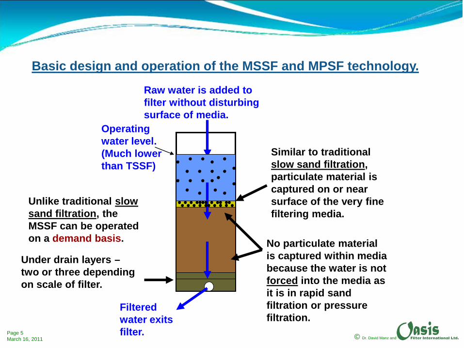
Operating water level. (Much lower than TSSF)
Raw water is added to filter without disturbing surface of media.
Filtered water exits filter.
Similar to traditional slow sand filtration, particulate material is captured on or near surface of the very fine filtering media.
No particulate material is captured within media because the water is not forced into the media as it is in rapid sand filtration or pressure filtration.
Unlike traditional slow sand filtration, the MSSF can be operated on a demand basis.
Basic design and operation of the MSSF and MPSF technology.
Under drain layers –two or three depending on scale of filter.
© Dr. David Manz andPage 6March 16, 2011
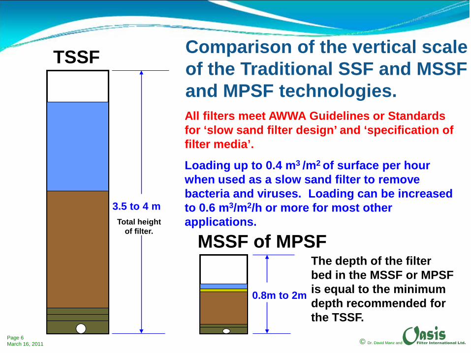
3.5 to 4 mTotal height
of filter.
TSSF Comparison of the vertical scale of the Traditional SSF and MSSF and MPSF technologies.All filters meet AWWA Guidelines or Standards for ‘slow sand filter design’ and ‘specification of filter media’.
Loading up to 0.4 m3 /m2 of surface per hour when used as a slow sand filter to remove bacteria and viruses. Loading can be increased to 0.6 m3/m2/h or more for most other applications.
0.8m to 2m
MSSF of MPSFThe depth of the filter bed in the MSSF or MPSF is equal to the minimum depth recommended for the TSSF.

© Dr. David Manz andPage 7March 16, 2011
Basic treatment process for iron and manganese removal:
1. Oxidation of iron and manganese (preferably using sodium hypochlorite).
2. Formation of micro-flocs.3. Filtration using MPSF.4. Storage and distribution.
(Possible to add additional pre- and post-treatment as required.)

© Dr. David Manz andPage 8March 16, 2011
First Understand Basic Principles of the Commissioning of the MPSF.
Note that an MPSF is backwashed as part of the commissioning process to insure that smallest sand/media particles (< 0.1 mm in diameter) are at the filter surface.
Almost ALL treatment occurs at or near the sand surface.

© Dr. David Manz andPage 9March 16, 2011
Review of Backwash Process
Consider a typical sand filter when first backwashed:
Initially particles having different diameters are mixed together.

© Dr. David Manz andPage 10March 16, 2011
Flow of Water
Backwash starts.

© Dr. David Manz andPage 11March 16, 2011
Bed fluidizes.
Flow of Water
© Dr. David Manz andPage 12March 16, 2011
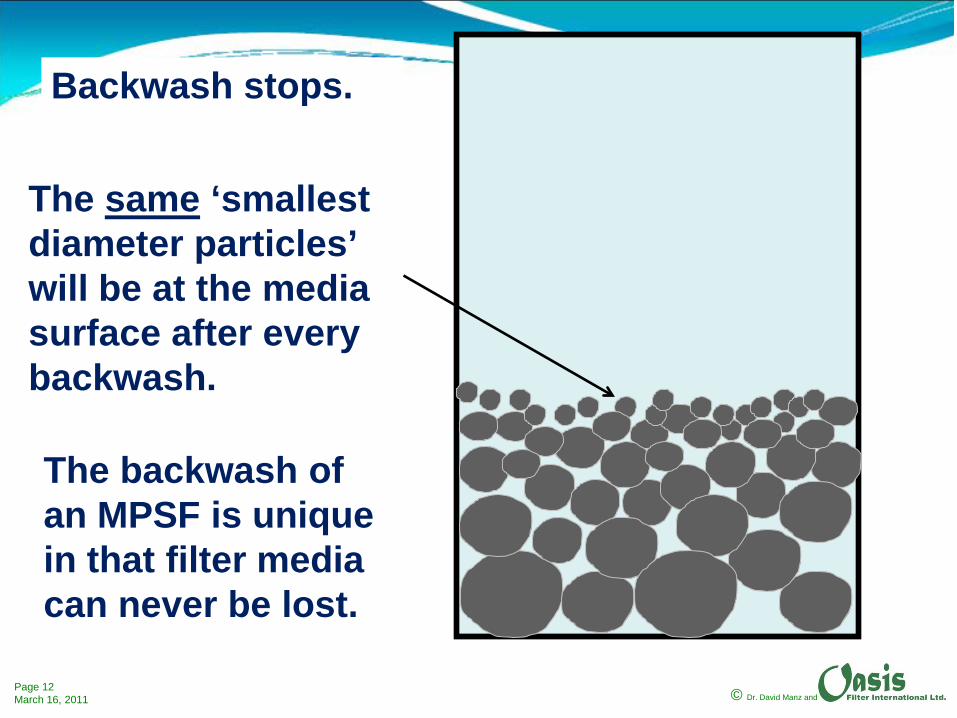
Backwash stops.
The same ‘smallest diameter particles’ will be at the media surface after every backwash.
The backwash of an MPSF is unique in that filter media can never be lost.
© Dr. David Manz andPage 13March 16, 2011
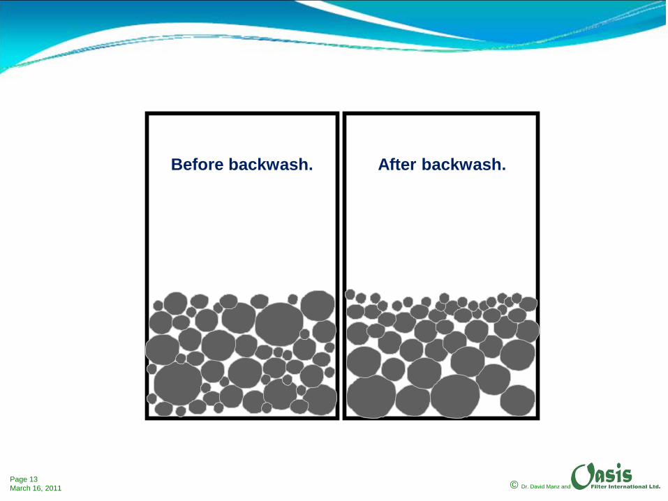
Before backwash. After backwash.
© Dr. David Manz andPage 14March 16, 2011
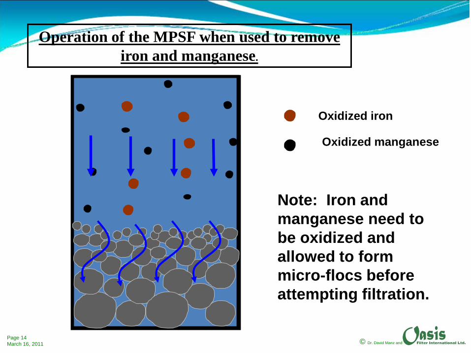
Operation of the MPSF when used to remove iron and manganese.
Oxidized iron
Oxidized manganese
Note: Iron and manganese need to be oxidized and allowed to form micro-flocs before attempting filtration.

© Dr. David Manz andPage 15March 16, 2011
Oxidized iron
Oxidized manganese
Operation of the MPSF when used to remove iron and manganese.
Iron and manganese are captured at the surface of the media – a mechanical filtration process that does not require formation of the ‘schmutzdeke’ that is developed by a traditional slow sand filter when removing micro-organisms.
© Dr. David Manz andPage 16March 16, 2011
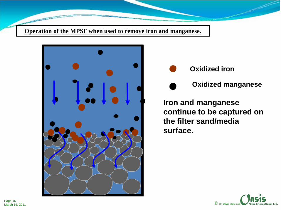
Oxidized iron
Oxidized manganese
Operation of the MPSF when used to remove iron and manganese.
Iron and manganese continue to be captured on the filter sand/media surface.
© Dr. David Manz andPage 17March 16, 2011
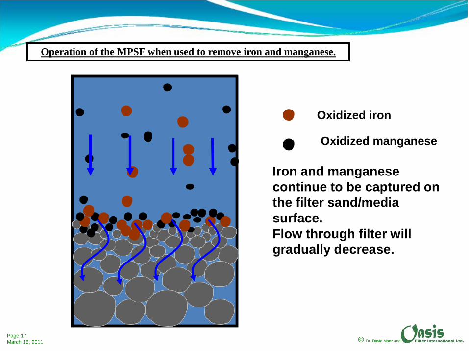
Oxidized iron
Oxidized manganese
Operation of the MPSF when used to remove iron and manganese.
Iron and manganese continue to be captured on the filter sand/media surface.Flow through filter will gradually decrease.

© Dr. David Manz andPage 18March 16, 2011
Oxidized iron
Oxidized manganese
Operation of the MPSF when used to remove iron and manganese.
Filter cleaning required.
Iron and manganese continue to be captured on the filter sand surface until such time as the filter sand surface is ‘plugged off’ and the flow through the filter is reduced to unacceptable rates. The filter needs to be cleaned.

© Dr. David Manz andPage 19March 16, 2011
Normal Cleaning of MPSF1. Filtered water is added into bottom of filter – backwash flow.
2. Surface layer of media is fluidized and expanded.
3. Backwash flow is stopped and media settles back into position.
4. Water containing captured iron and manganese is flushed out.
Entire cleaning process takes less than 30 minutes even for very large filters.
No media is removed or needs to be replaced.

© Dr. David Manz andPage 20March 16, 2011
Filtered water enters filter.
Backwashing suspends particulate material that had blocked flow from top of sand/media.
Only the layer of fine filtering sand/media needs to be expanded and captured particles are flushed from it.
Normal Cleaning of MPSF
Top layer expanded.
Or whole filtering layer expanded.

© Dr. David Manz andPage 21March 16, 2011
Water containing all of the captured material is decanted from filter.
Decanted water is sent to waste.
Decant is complete.
Not possible to lose media during backwash
process!
Filter is put into production
without filter-to-waste cycle.
Top layer collapses to original depth.
Backwash is stopped – smallest sand particles remain at surface.
© Dr. David Manz andPage 22March 16, 2011
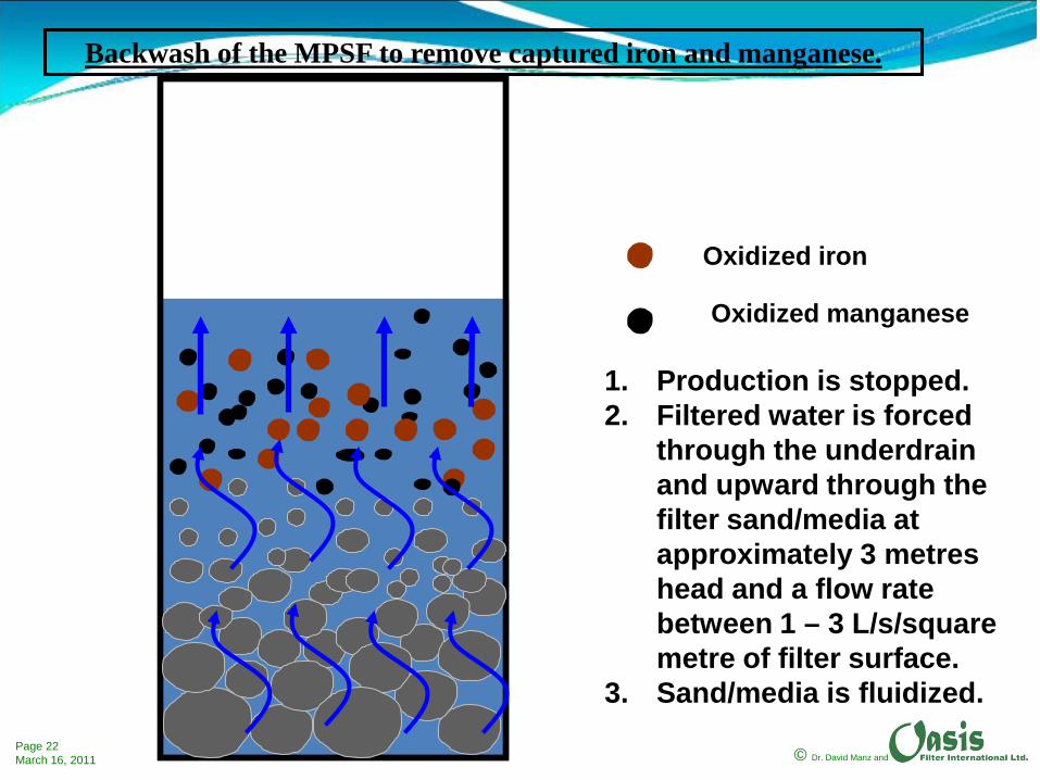
Oxidized iron
Oxidized manganese
Backwash of the MPSF to remove captured iron and manganese.
1. Production is stopped.2. Filtered water is forced
through the underdrain and upward through the filter sand/media at approximately 3 metres head and a flow rate between 1 – 3 L/s/square metre of filter surface.
3. Sand/media is fluidized.

© Dr. David Manz andPage 23March 16, 2011
Oxidized iron
Oxidized manganese
Backwash of the MPSF to remove captured iron and manganese.
1. Backwash continues until all of the iron and manganese is suspended in the water above the fluidized sand/media.
2. Water is not wasted during the backwash process.

© Dr. David Manz andPage 24March 16, 2011
Oxidized iron
Oxidized manganese
1. All of the iron and manganese that was captured on the sand/media surface is suspended in the water above the filter sand/media (less than 1 metre depth).
Backwash of the MPSF to remove captured iron and manganese.

© Dr. David Manz andPage 25March 16, 2011
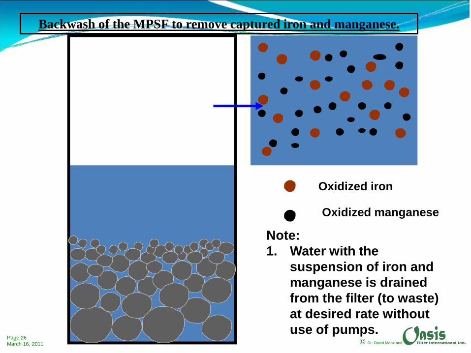
Oxidized iron
Oxidized manganese
Backwash of the MPSF to remove captured iron and manganese.
Note: 1. Backwash is stopped.2. Sand/media settles back
to original position with finest particles at the top.
© Dr. David Manz andPage 26March 16, 2011
Oxidized iron
Oxidized manganese
Backwash of the MPSF to remove captured iron and manganese.
Note: 1. Water with the
suspension of iron and manganese is drained from the filter (to waste) at desired rate without use of pumps.

© Dr. David Manz andPage 27March 16, 2011
Filter is put back into production.
Oxidized iron
Oxidized manganese
Note: Entire backwash process may take 30 minutes -more or less.
© Dr. David Manz andPage 28March 16, 2011
Consider the operation and cleaning of a pilot scale MPSF.

© Dr. David Manz andPage 29March 16, 2011
Water with oxidized iron or manganese is introduced to the top of the filter.Note that ALL iron or manganese is captured at sand/media surface.

© Dr. David Manz andPage 30March 16, 2011
Water appearance before and after filtration.
© Dr. David Manz andPage 31March 16, 2011
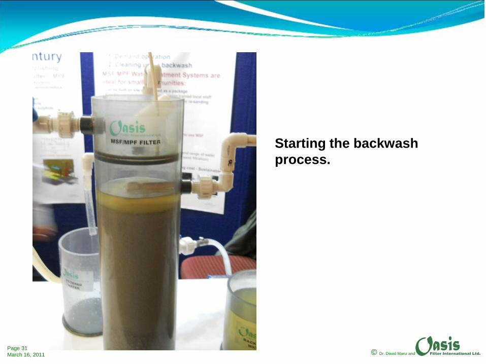
Starting the backwash process.
© Dr. David Manz andPage 32March 16, 2011
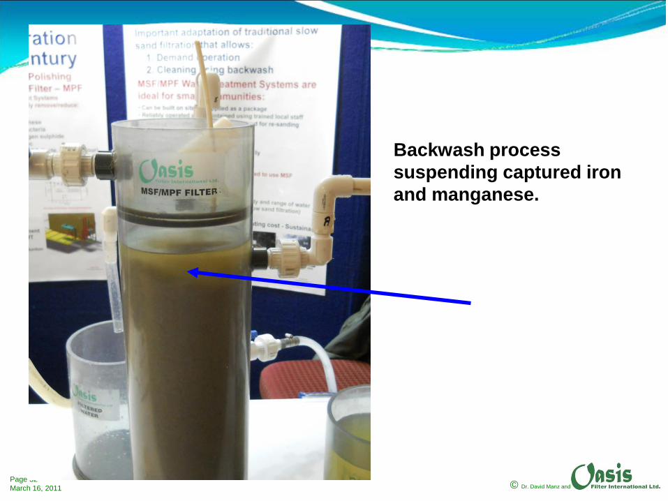
Backwash process suspending captured iron and manganese.
© Dr. David Manz andPage 33March 16, 2011
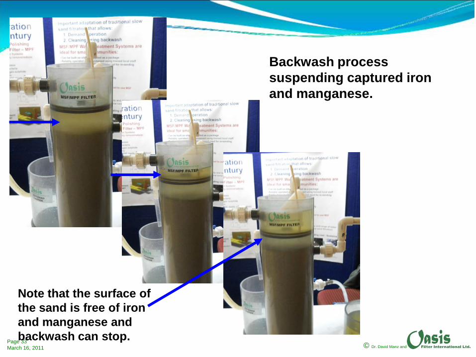
Backwash process suspending captured iron and manganese.
Note that the surface of the sand is free of iron and manganese and backwash can stop.

© Dr. David Manz andPage 34March 16, 2011
Backwash is stopped and the sand/media is allowed to settle.
Sand returns to original position.
© Dr. David Manz andPage 35March 16, 2011
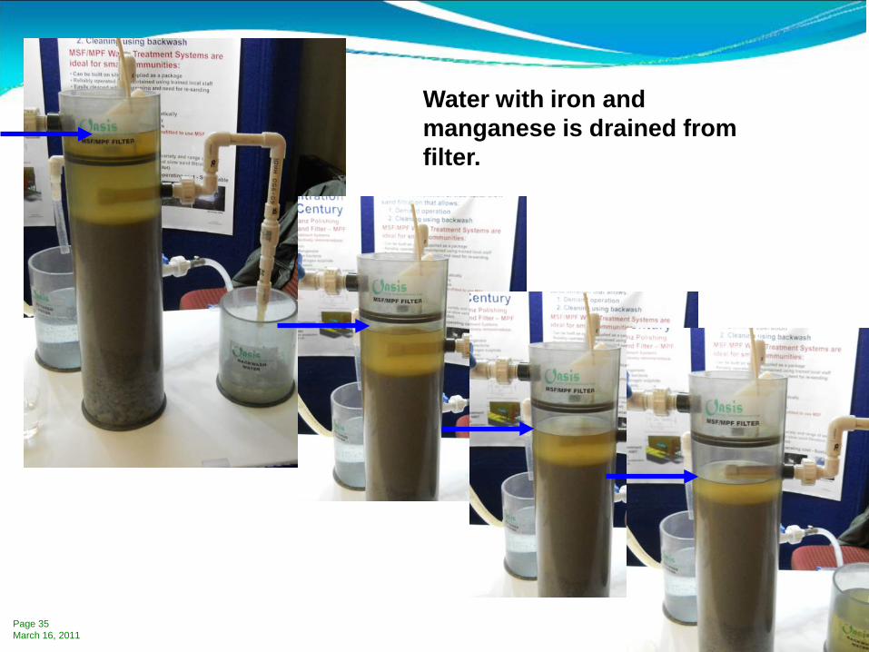
Water with iron and manganese is drained from filter.

© Dr. David Manz andPage 36March 16, 2011
Water with iron and manganese is completely drained from filter.
Captured iron and manganese in the backwash water will settle quickly allowing the clarified water to be recycled leaving very little sludge for disposal.
© Dr. David Manz andPage 37March 16, 2011
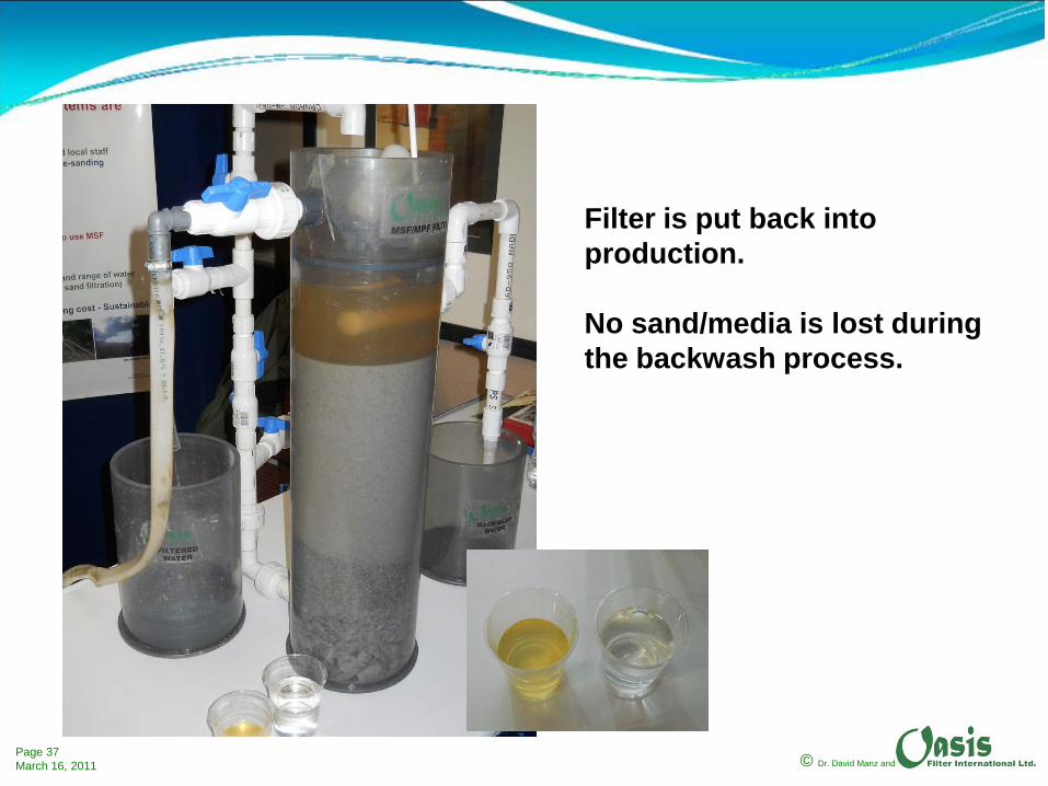
Filter is put back into production.
No sand/media is lost during the backwash process.

© Dr. David Manz andPage 38March 16, 2011
Stavely Water Treatment PlantAlberta, Canada Manganese Removal Using MSPF Technology
© Dr. David Manz andPage 39March 16, 2011
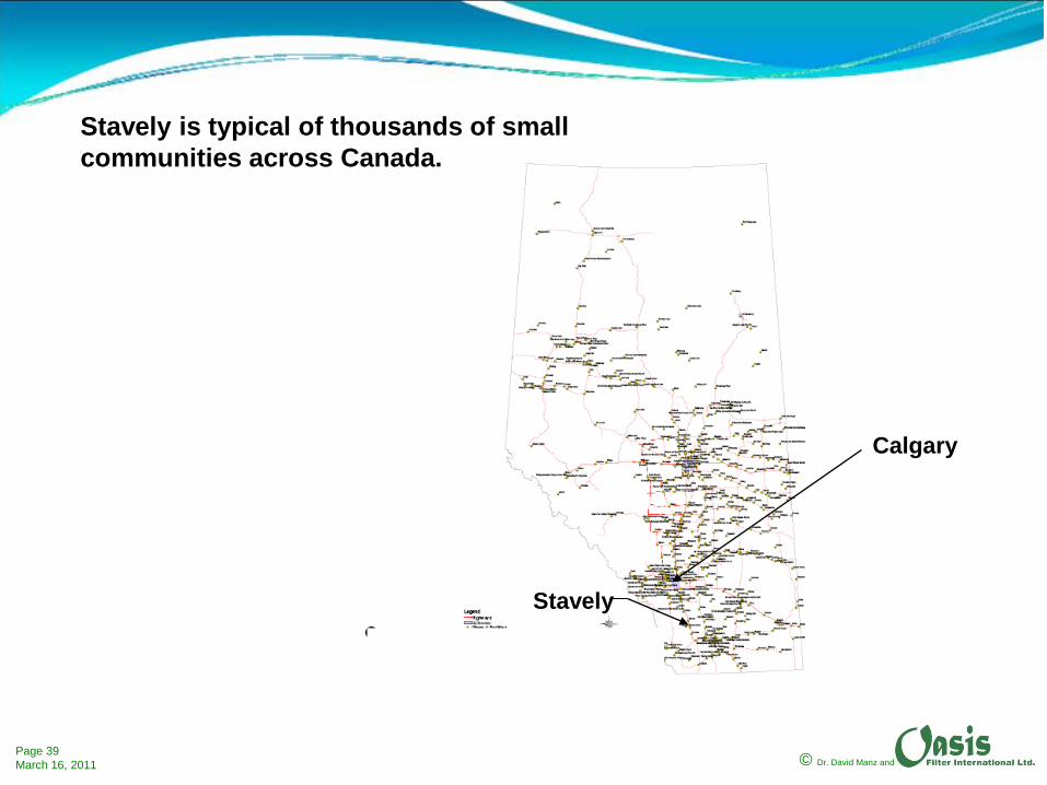
Stavely is typical of thousands of small communities across Canada.
Stavely
Calgary

© Dr. David Manz andPage 40March 16, 2011
Summary of design constraints and objectives•Groundwater supply not under direct influence of surface water.
•Manganese above 0.05 mg/L (as high as 0.4 mg/L), hydrogen sulfide (detectable odor) and presence of sulfate reducing bacteria.
•Required treatment capacity of 1,200 m3/day or 50,000 litres per hour.
•Minimum chemical requirements.
•Minimum level of automation.
•Minimum complexity – Operator Level 1 if possible.
•Backwash water to be disposed in town lagoon through existing sanitary sewer.
© Dr. David Manz andPage 41March 16, 2011
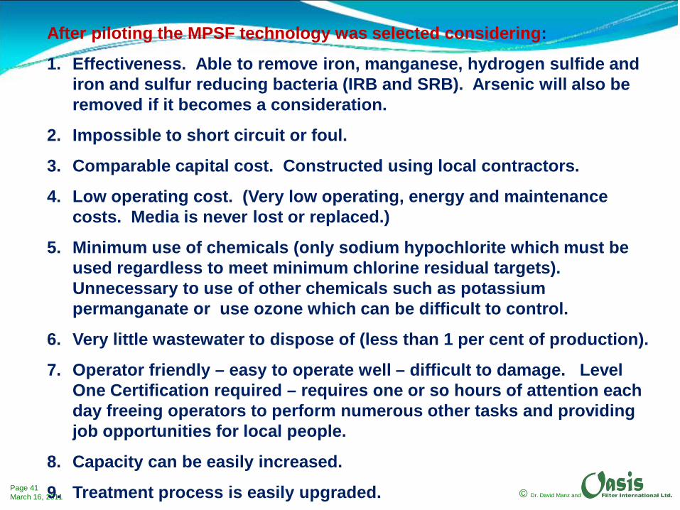
After piloting the MPSF technology was selected considering:
1. Effectiveness. Able to remove iron, manganese, hydrogen sulfide and iron and sulfur reducing bacteria (IRB and SRB). Arsenic will also be removed if it becomes a consideration.
2. Impossible to short circuit or foul.
3. Comparable capital cost. Constructed using local contractors.
4. Low operating cost. (Very low operating, energy and maintenance costs. Media is never lost or replaced.)
5. Minimum use of chemicals (only sodium hypochlorite which must be used regardless to meet minimum chlorine residual targets). Unnecessary to use of other chemicals such as potassium permanganate or use ozone which can be difficult to control.
6. Very little wastewater to dispose of (less than 1 per cent of production).
7. Operator friendly – easy to operate well – difficult to damage. Level One Certification required – requires one or so hours of attention each day freeing operators to perform numerous other tasks and providing job opportunities for local people.
8. Capacity can be easily increased.
9. Treatment process is easily upgraded.

© Dr. David Manz andPage 42March 16, 2011
Process Flow Diagram - Stavely
MPSF6 Cells
© Dr. David Manz andPage 43March 16, 2011
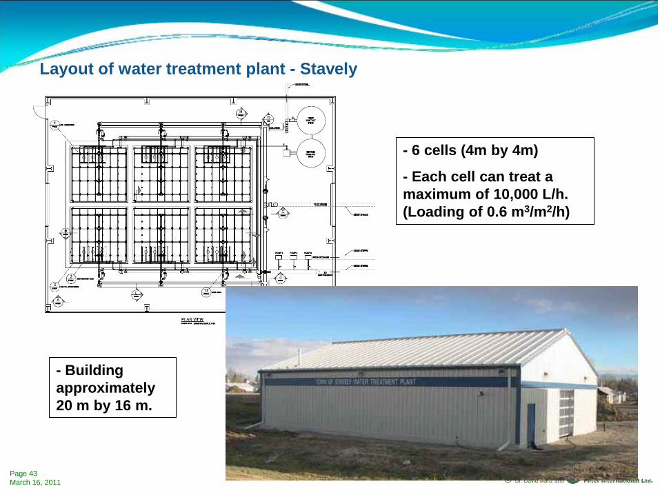
- 6 cells (4m by 4m)
- Each cell can treat a maximum of 10,000 L/h. (Loading of 0.6 m3/m2/h)
Layout of water treatment plant - Stavely
- Building approximately 20 m by 16 m.
© Dr. David Manz andPage 44March 16, 2011
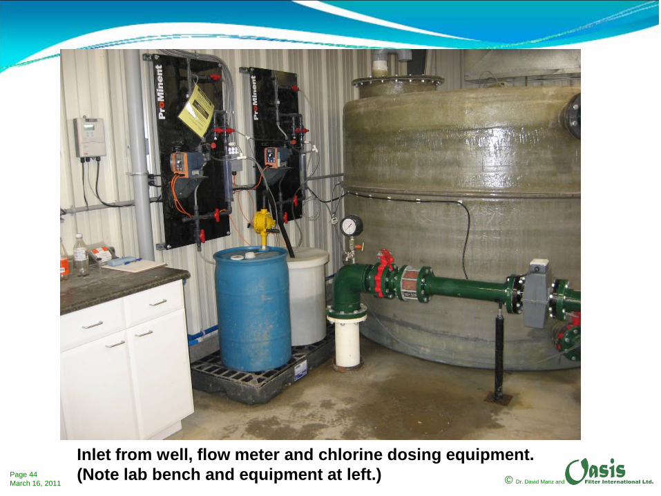
Inlet from well, flow meter and chlorine dosing equipment.(Note lab bench and equipment at left.)
© Dr. David Manz andPage 45March 16, 2011
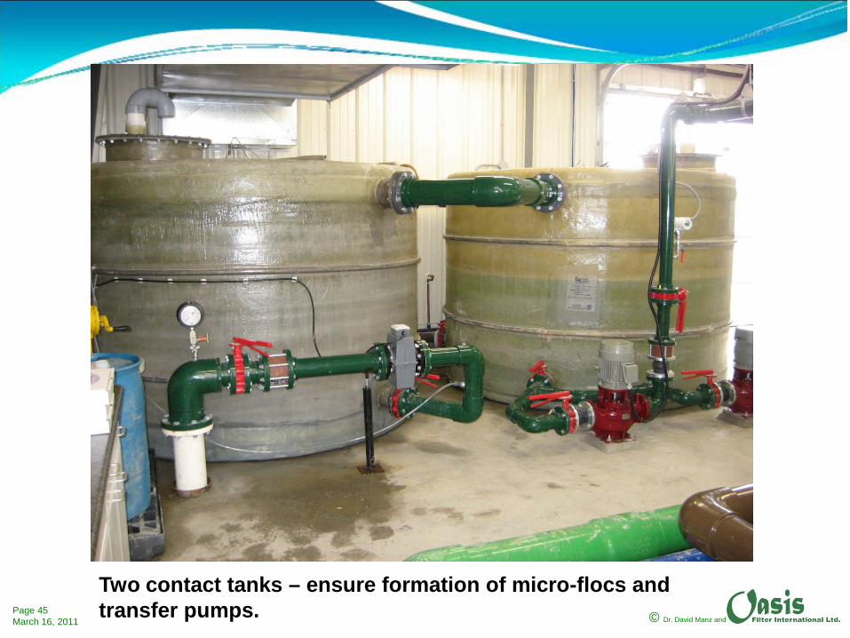
Two contact tanks – ensure formation of micro-flocs and transfer pumps.

© Dr. David Manz andPage 46March 16, 2011
View of raw water inlet, contact tanks, transfer pumps and lab.

© Dr. David Manz andPage 47March 16, 2011
Operating filters in Stavely water treatment plant.

© Dr. David Manz andPage 48March 16, 2011
Interior of Stavely water treatment plant.

© Dr. David Manz andPage 49March 16, 2011
Raw water inlet, filtered water outlet, backwash water inlet and wastewater outlet. (Note MCC.)

© Dr. David Manz andPage 50March 16, 2011
Operation consists of fully opening or closing a valve named the ‘Operate Valve’.
Flow adjustment consists of setting the valve named ‘Control Valve’. This valve is typically set at time of commissioning and not adjusted again (at least not often).
© Dr. David Manz andPage 51March 16, 2011
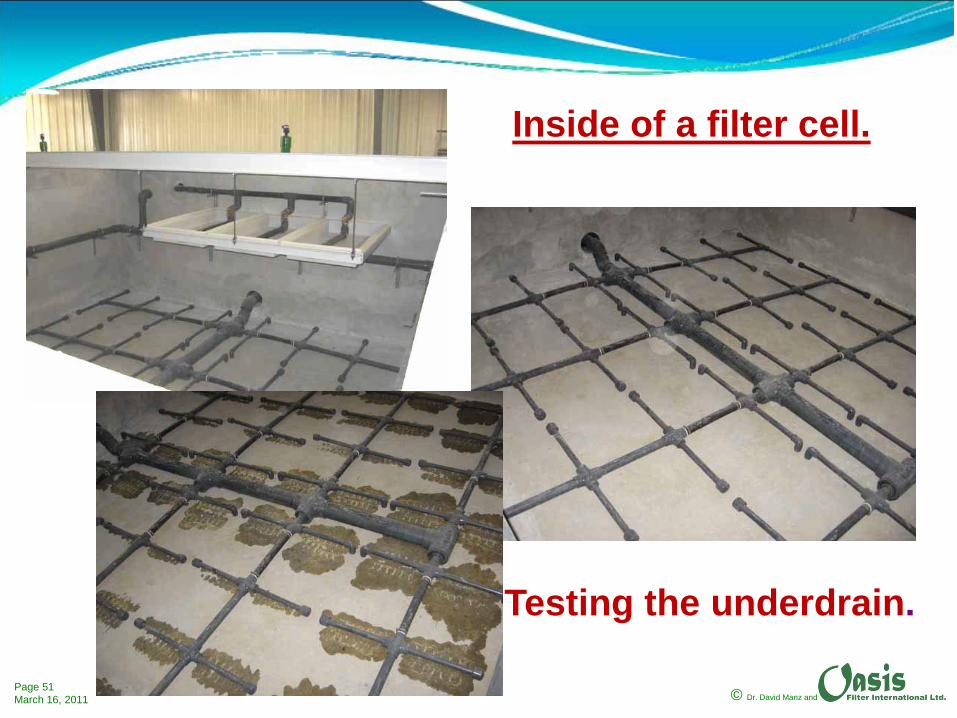
Inside of a filter cell.
Testing the underdrain.
© Dr. David Manz andPage 52March 16, 2011
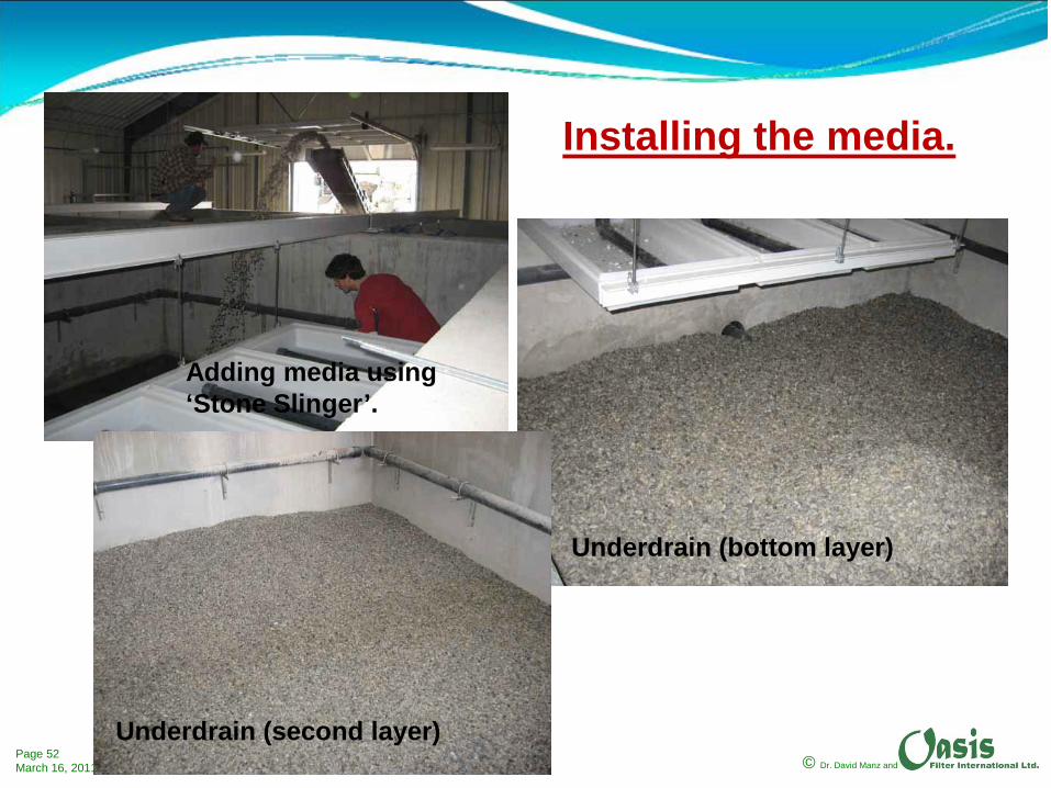
Installing the media.
Underdrain (bottom layer)
Underdrain (second layer)
Adding media using ‘Stone Slinger’.

© Dr. David Manz andPage 53March 16, 2011
Filter media (top layer)
Filter media (bottom layer)
Underdrain (third layer)
Installing the media.

© Dr. David Manz andPage 54March 16, 2011
Operating Filter

© Dr. David Manz andPage 55March 16, 2011
Backwash in Progress
Backwash once every six weeks –one cell per week (30 min.).
Produce 6 m3
wastewater per backwash per cell.
Wastewater is less than 1 % of production.
(36 m3 of wastewater with 42,000 m3 of production.)
Depth of bed fluidization.
© Dr. David Manz andPage 56March 16, 2011
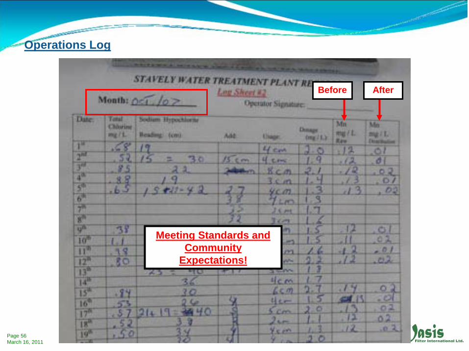
Before After
Meeting Standards and Community
Expectations!
Operations Log
© Dr. David Manz andPage 57March 16, 2011
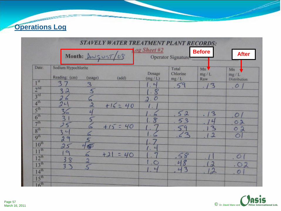
Before After
Operations Log

© Dr. David Manz andPage 58March 16, 2011
© Dr. David Manz andPage 59March 16, 2011
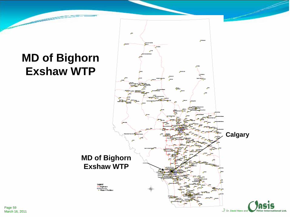
MD of BighornExshaw WTP
Calgary
MD of BighornExshaw WTP

© Dr. David Manz andPage 60March 16, 2011
Process Flow Diagram - Exshaw
MPSF4 Cells
© Dr. David Manz andPage 61March 16, 2011
Summary of design constraints and objectives•Groundwater supply not under direct influence of surface water.•Iron above 0.3 mg/L (during pilot testing concentration was above 1.4 mg/L).•Manganese above 0.2 mg/L.•Hydrogen sulfide (and presence of sulfate reducing bacteria) present during pilot test.•Required treatment capacity of 1,200 m3/day or 50,000 litres per hour.•Minimum chemical requirements.•Minimum level of automation.•Minimum complexity – Operator Level 1 if possible.•Backwash water to be disposed in town lagoon through existing sanitary sewer.
After piloting the MPSF technology was chosen for same reasons the MPSF technology was chosen in Stavely.

© Dr. David Manz andPage 62March 16, 2011
Bench scaleevaluation is performed prior to pilot scale studies –normally at no cost to client.
Piloting based on results of bench scale testing.
© Dr. David Manz andPage 63March 16, 2011
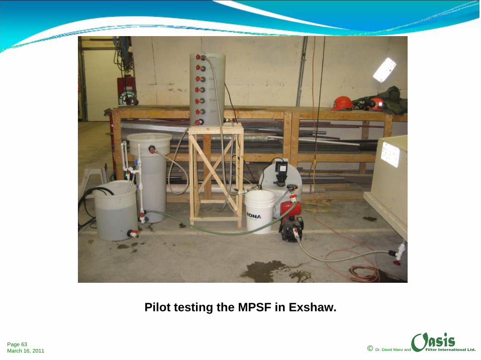
Pilot testing the MPSF in Exshaw.
© Dr. David Manz andPage 64March 16, 2011
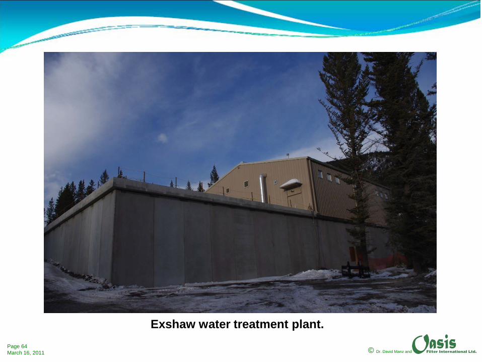
Exshaw water treatment plant.

© Dr. David Manz andPage 65March 16, 2011
Inside Exshaw water treatment plant showing four filters and three contact tanks.
© Dr. David Manz andPage 66March 16, 2011
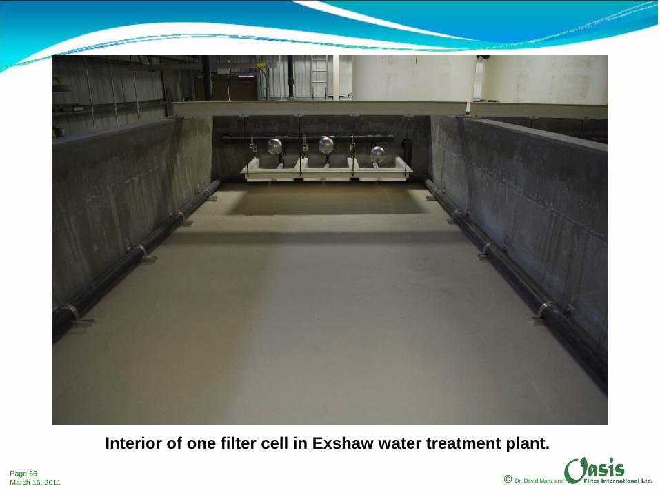
Interior of one filter cell in Exshaw water treatment plant.
© Dr. David Manz andPage 67March 16, 2011
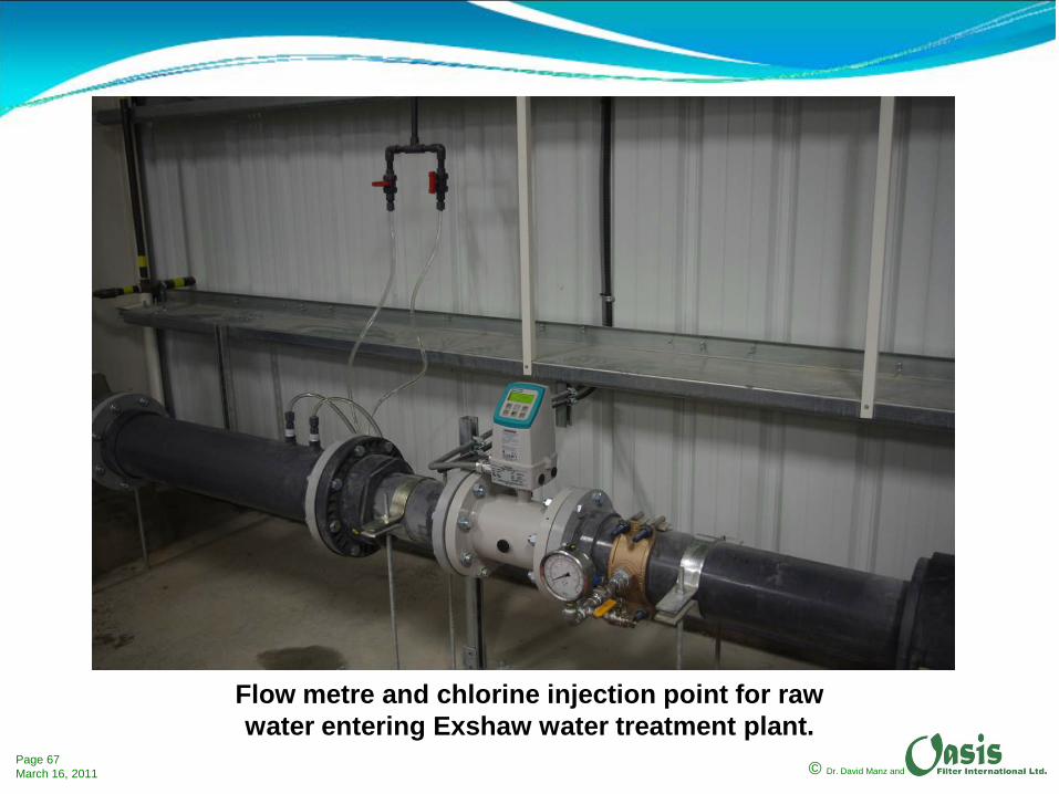
Flow metre and chlorine injection point for raw water entering Exshaw water treatment plant.
© Dr. David Manz andPage 68March 16, 2011
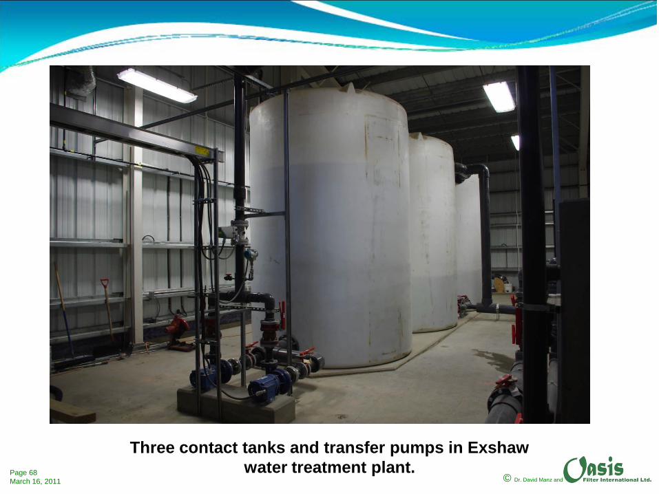
Three contact tanks and transfer pumps in Exshaw water treatment plant.
© Dr. David Manz andPage 69March 16, 2011
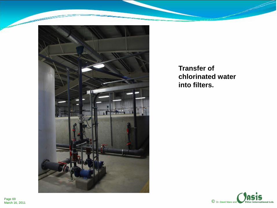
Transfer of chlorinated water into filters.

© Dr. David Manz andPage 70March 16, 2011
Raw water inlet and wastewater removal.
© Dr. David Manz andPage 71March 16, 2011
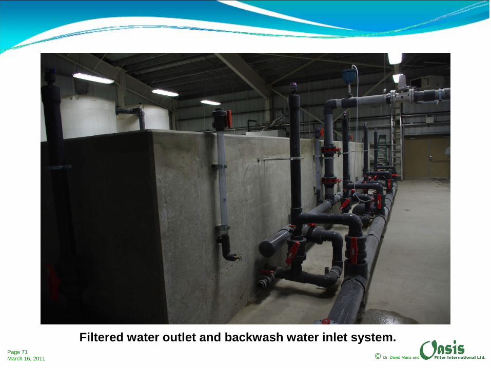
Filtered water outlet and backwash water inlet system.

© Dr. David Manz andPage 72March 16, 2011
Filtered water outlet and backwash water inlet system.

© Dr. David Manz andPage 73March 16, 2011
Diffuser basins showing mechanical float valves that control the flow of raw water into filter.

© Dr. David Manz andPage 74March 16, 2011
Operating filter in the Exshaw water treatment plant.
© Dr. David Manz andPage 75March 16, 2011
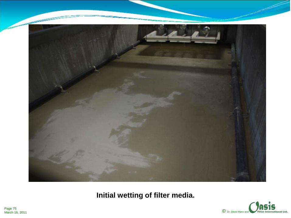
Initial wetting of filter media.

© Dr. David Manz andPage 76March 16, 2011
Beginning of first backwash.

© Dr. David Manz andPage 77March 16, 2011
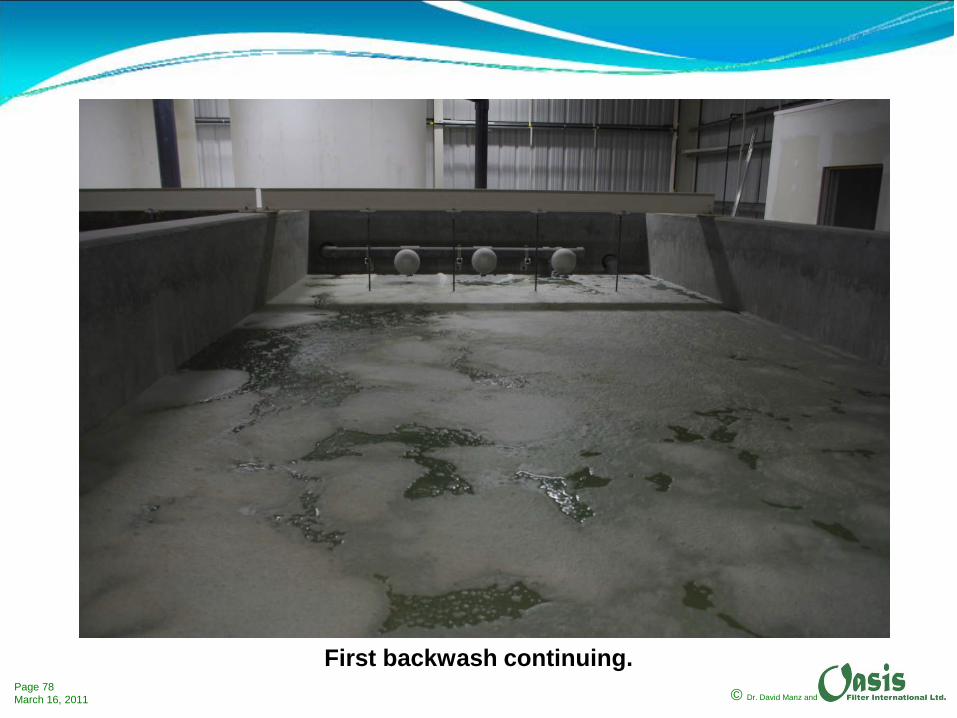
First backwash continuing.
© Dr. David Manz andPage 78March 16, 2011
First backwash continuing.

© Dr. David Manz andPage 79March 16, 2011
Backwash completed – sand/media allowed to settle.

© Dr. David Manz andPage 80March 16, 2011
Filter after removal of backwash water.
© Dr. David Manz andPage 81March 16, 2011
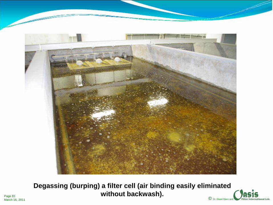
Degassing (burping) a filter cell (air binding easily eliminated without backwash).
© Dr. David Manz andPage 82March 16, 2011
Performance of Exshaw WTP:
1. Sodium hypochlorite dose approximately 1.0 mg/L at inlet to contact tanks.
2. Iron removal to less than 0.05 mg/L.3. Manganese removal to less than 0.05 mg/L.4. Free chlorine in filtered water approximately
0.6 mg/L.
© Dr. David Manz andPage 83March 16, 2011
MPSF based treatment systems can be adapted to treat:
1. GWUDI that also has elevated iron and manganese concentrations.
2. Groundwater with arsenic (and other heavy metals).3. Groundwater with ammonia.4. Groundwater with elevated concentrations of fluoride.5. Groundwater with elevated NOM (TOC or DOC).6. Surface water with elevated concentrations of iron or
manganese.
Pre-treatment or post-treatment can be used as required (such as the use of alum, PAC or other coagulants, roughing filters, GAC, UV and specialized oxidants).
© Dr. David Manz andPage 84March 16, 2011
It is important to emphasize the advantages of using the MPSF technology include:
1. Iron and manganese removal water treatment plants can be operated by Level 1 operators greatly facilitating staffing and local employment.
2. Typically meet 2012 standards without significant or any modification.

© Dr. David Manz andPage 85March 16, 2011
Any shape.
MPSF filter cells can vary in capacity.
300 - 15,000 L/h
60,000 L/h
240,000 L/h
Designs have been evaluated at proto-type scale.
Retrofitting existing traditional slow sand filtration.

© Dr. David Manz andPage 86March 16, 2011
Possible configurations of MPSF or MSSF cells.
MPSF or MSSF cells may also be ‘stacked’ as in a multi-floor building.

© Dr. David Manz andPage 87March 16, 2011
The MPSF and MSSF units can be constructed using concrete, aluminum, stainless steel, medium density polyethylene, fibreglass and concrete block technology depending on clients needs (remoteness of community, etc.).
Oasis can provide entire filter units or only the critical piping and media (vessel would be constructed to Oasis specifications).
Oasis works closely with client consulting engineers and regulatory bodies.
© Dr. David Manz andPage 88March 16, 2011
The MPSF technology provides significant opportunities for small communities to meet their water treatment needs (iron, manganese and arsenic removal) at low cost in a manner consistent with local values and recruitment of operators from their own community.
The MSSF technology provides similar advantages.
© Dr. David Manz andPage 89March 16, 2011
MPSF Water Treatment Systems are ideal for small communities:
• Can be built on site or supplied as a package or partial package.
• Reliably operated and maintained using trained local staff.• Easily cleaned without scraping and need for re-sanding.• Minimal energy use.• Minimum use of chemicals.• Minimum production of wastewater.• Can be operated manually or automatically.• Can be monitored locally or remotely.• Appropriate for isolated communities• Existing traditional SSF’s can be retrofitted to use MSF
technology to achieve• Greater capacity.• Significantly less effort to clean.
• Appropriate for treatment of a wide variety and range of water quality (well beyond that of traditional slow sand filtration).
• Easily evaluated (bench scale and pilot).

© Dr. David Manz andPage 90March 16, 2011
Thank you.
2525 Macleod Trail SWCalgary, Alberta, CanadaT2G 5J4Ph (403) 269-1555 / fax (403) 264-6244E-mail: [email protected]: www.oasisfilter.com