marine bridge system displays - rugged mobile...
TRANSCRIPT

Users Manual Marine Bridge System Displays
Marine Bridge System Displays
USERS MANUAL
Version: 1.2
R08T200-MR 8.4 inch Marine Bridge Display R10L100-MR 10.4 inch Marine Bridge Display R12L600-MR 12.1 inch Marine Bridge Display R15T600-MR 15.0 inch Marine Bridge Display R17L500-MR 17.0 inch Marine Bridge Display R19L300-MR 19.0 inch Marine Bridge Display R20L100-MR 20.1 inch Marine Bridge Display R23L100-MR 23.1 inch Marine Bridge Display

Users Manual Marine Bridge System Displays
REVISION HISTORY
REVISION AUTHOR DATE DESCRIPTION 1.00 Wayne Lin April 27, 2007 First version release
1.10 Wayne Lin Sep. 10, 2007 Add certificate serial number label.
1.20 Ethan Wang May 13, 2010 Add simply trouble shooting guide and
point out DNV approved mounting
method.
Copyright @2007 Winmate Communication INC.

Users Manual Marine Bridge System Displays 2
IMPORTANT SAFETY INSTRUCTIONS
Please read these instructions carefully before using the product and save for later reference.
Follow all warnings and instructions marked on the product.
Unplug this product from the wall outlet before cleaning. Clean the product with a damp soft cloth. Do not use liquid or aerosol cleaners as it may cause permanent damage to the screen.
Do not use this product near water.
Do not place this product on an unstable cart, stand, or table. The product may fall, causing serious damage to the product.
This product should be operated from the type of power indicated on the marking label. If you are not sure of the type of power available, consult your dealer or local power company.
This product is equipped with a 3-wire grounding type plug, a plug having a third (grounding) pin. This plug will only fit into a grounding-type power outlet. This is a safety feature. If you are unable to insert the plug into the outlet, contact your electrician to replace your obsolete outlet. (For AC version only) Do not defeat the purpose of the grounding-type plug.
Do not allow anything to rest on the power cord. Do not locate this product where persons will walk on the cord.
Never push objects of any kind into this product through cabinet slots as they may touch dangerous voltage points or short out parts that could result in a risk of fire or electric shock. Never spill liquid of any kind on the product.
Do not attempt to service this product yourself, as opening or removing covers may expose you to dangerous voltage points or other risks and will void the warranty. Refer all servicing to qualified service personnel.
Unplug this product from the wall outlet and refer servicing to qualified service personnel under the following conditions:
When the power cord or plug is damaged or frayed.
If liquid has been spilled into the product.
If the product has been exposed to rain or water.
If the product does not operate normally when the operating instructions are followed. Adjust only those controls that are covered by the operating instructions since improper adjustment of other controls may result in damage and will often require extensive work by a qualified technician to restore the product to normal operation.
If the product has been dropped or the cabinet has been damaged.
If the product exhibits a distinct change in performance, indicating a need for service.
Users Manual Marine Bridge System Displays 3
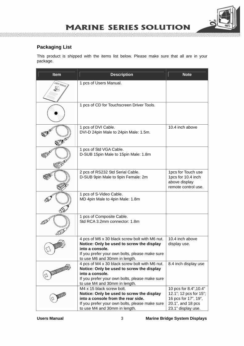
Packaging List
This product is shipped with the items list below. Please make sure that all are in your package.
Item Description Note
1 pcs of Users Manual.
1 pcs of CD for Touchscreen Driver Tools.
1 pcs of DVI Cable. DVI-D 24pin Male to 24pin Male: 1.5m.
10.4 inch above
1 pcs of Std VGA Cable. D-SUB 15pin Male to 15pin Male: 1.8m
2 pcs of RS232 Std Serial Cable. D-SUB 9pin Male to 9pin Female: 2m
1pcs for Touch use 1pcs for 10.4 inch above display remote control use.
1 pcs of S-Video Cable. MD 4pin Male to 4pin Male: 1.8m
1 pcs of Composite Cable. Std RCA 3.2mm connector: 1.8m
4 pcs of M6 x 30 black screw bolt with M6 nut.Notice: Only be used to screw the display into a console. If you prefer your own bolts, please make sure to use M6 and 30mm in length.
10.4 inch above display use.
4 pcs of M4 x 30 black screw bolt with M6 nut.Notice: Only be used to screw the display into a console. If you prefer your own bolts, please make sure to use M4 and 30mm in length.
8.4 inch display use
M4 x 15 black screw bolt. Notice: Only be used to screw the display into a console from the rear side. If you prefer your own bolts, please make sure to use M4 and 30mm in length.
10 pcs for 8.4”,10.4” 12.1”; 12 pcs for 15”; 16 pcs for 17”, 19”, 20.1”, and 18 pcs 23.1” display use.
Users Manual Marine Bridge System Displays 4
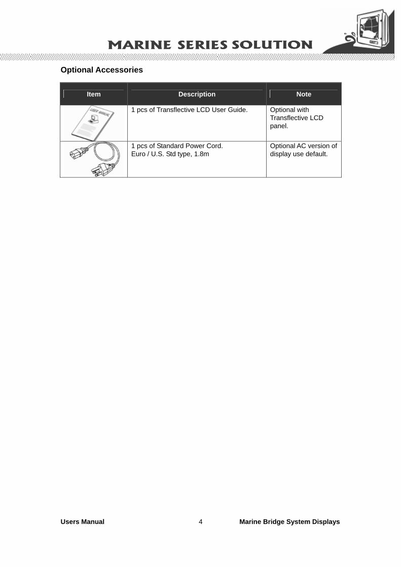
Optional Accessories
Item Description Note
1 pcs of Transflective LCD User Guide. Optional with Transflective LCD panel.
1 pcs of Standard Power Cord. Euro / U.S. Std type, 1.8m
Optional AC version of display use default.

Users Manual Marine Bridge System Displays 5
Contents IMPORTANT SAFETY INSTRUCTIONS.........................................................2 PACKAGING LIST ..........................................................................................3 CHAPTER 1 GENERAL INFORMATION......................................................7
1.1 FEATURES ABOUT THE MARINE BRIDGE SYSTEM DISPLAY..........................................................7 1.2 BASIC CONSTRUCTION OF MARINE BRIDGE SYSTEM DISPLAY....................................................9 1.3 TOUCH SCREEN SOLUTION (OPTIONAL) .....................................................................................10
1.3.1 Five-Wire Resistive Touch screen (Optional 1)....................................................................10 1.3.2 SecureTouch Surface Wave Touch screen (Optional 2)....................................................... 11
1.4 CERTIFICATE SERIAL NUMBER LABEL .......................................................................................12 CHAPTER 2 INSTALLATION .....................................................................15
2.1 GENERAL INSTALLATION .............................................................................................................15 2.2 INSTALLATION NOTICE ................................................................................................................18
2.2.1 Brightness Control Knob Precaution ...................................................................................18 2.2.2 Cable Connection Precaution...............................................................................................18
CHAPTER 3 OPERATION OF THE LCD DISPLAY ...................................20 3.1 INPUT / OUTPUT SIGNALS OVERVIEW .........................................................................................20 3.2 OSD USER CONTROLS .................................................................................................................22 3.3 PIP (PICTURE IN PICTURE) FUNCTION........................................................................................23 3.4 AUTO ADJUSTMENT FUNCTION ...................................................................................................23 3.5 SOURCE FUNCTION ......................................................................................................................24 3.6 OSD MENU FUNCTION.................................................................................................................25
3.6.1 Display Item Menu ...............................................................................................................26 3.6.2 Image Item Menu .................................................................................................................27 3.6.3 Position Item Menu ..............................................................................................................30 3.6.4 Color Item Menu...................................................................................................................32 3.6.5 PIP Control Item Menu ........................................................................................................34 3.6.6 Main Display Item Menu......................................................................................................35 3.6.7 PIP Display Item Menu ........................................................................................................36 3.6.8 Audio Item Menu (Optional) ................................................................................................37 3.6.9 Reset Item Menu...................................................................................................................38
3.7 SIMPLY ROUBLE SHOOTING GUIDE…………………………………… ......…………………….38 APPENDIX A: CLEANING THE MONITOR ..................................................40 APPENDIX B: DISCLAIMER AND TROUBLESHOOTING...........................41
DISCLAIMER.......................................................................................................................................41 TROUBLESHOOTING...........................................................................................................................41
APPENDIX C: SUPPORTED MODES ..........................................................42 APPENDIX D: RS-232 COMMAND CODE(OPTIONAL) ..............................43 APPENDIX E: SUNLIGHT READABLE (TRANSFLECTIVE) OUTDOOR READABILITY (OPTIONAL) .........................................................................44

Users Manual Marine Bridge System Displays 6
CHAPTER 1 General Information

Users Manual Marine Bridge System Displays 7
Chapter 1 General Information
The Marine Bridge System Displays are an extraordinary display design with sunlight readable high quality panel, dimming brightness, ease of use OSD front panel control, IP65 proof, multi-scan video function, high quality touchscreen, wide voltage range power input acceptable, and anti-corrosion protection. Born to the demands of maritime applications such as navigation, ship automation and surveillance. All product designs follow IEC-60945 Maritime Navigation and Radio-communication Equipment and Systems requirements. 1.1 Features about the Marine Bridge System Display Here are features of Marine Bridge System Displays:
Full-range durable displays The Marine Bridge System Displays use high quality branding TFT LCD displays with high resolution and wide temperature range panels. From 8.4 inch to 23.1 inch, we offer a wide range choice fulfilling any demand in Marine market.
Hyper Dimming
Our displays use hyper dimming technology that can control backlight brightness linearly from nearly 0% to 100% by a dimming knob. In the night vision it’s very suitable for marine applications.
Sunlight Readable (Optional)
Our extraordinary transflective film technology enhances visibility for Marine outdoor or bright ambience environment. (Outdoor readability please take reference to Appendix E)
Anti-corrosion IP Proof (Optional)
The Marine displays design with panel (flush) mount IP65 aluminum housing with powder coating design (IP54 rear) achieve the anti-corrosion proof in harsh conditions.
Wide Voltage Input Range Power Input
For marine and transportation power source characteristic, our displays use wide voltage range from 8 to 36V input acceptable. AC power input is also optional for several models from 12 inch to 23.1 inch.
For 12.1 inch to 23.1 inch display, the AC power source is also available for option.
Touchscreen / Anti-reflection Protection Glass
We develop highly compatible mechanical design for each type. Customers can choose high quality SAW touchscreen, 5 wire resistive touchscreen, or even anti-reflection protection glass for option.

Users Manual Marine Bridge System Displays 8
Multi-scan Function
The display can accept multi-video inputs as DVI, VGA, S-Video or Composite for example. From 10.4 inch to 23.1 inch displays, our outstanding scaling board design also support PIP (picture in picture) function for special marine applications.
IP65 OSD Front Panel Design
With IP65 water-dust front bezel proof, the Marine Bridge System Displays use easy to use front panel OSD control. It’s very convenience and intelligent design for all maritime users.
Anti-Shock and Vibration
Enhanced shock and vibration resistance.
Customize your marine products
Base on our well-experience modulized competence, we can do very flexible and tailor-made design fulfilling any of customer’s solution. For different panel characteristics, mechanical design, and electronic component, we can make it for you.
Approved Marine Displays
Winmate Marine Bridge System Display design are all followed IEC-60945 Maritime Navigation and Radio-communication Equipment and Systems requirements.
The Marine Bridge System Display series consists wide range sizes from 8.4 inches to 23.1 inches. By testing for usability in a ship’s wheelhouse during different ambient light conditions. All these models can fulfill most of the demands in maritime applications especially for navigation, ship automation and maritime surveillance.
About this Manual
The users’ manual introduce basic information about the product, electrical, mechanical and input / output signal specifications. All specification are subject to change without prior notice due to manufacturing reasons. Check in the “Revision History” in front page of this manual for any update reference.

Users Manual Marine Bridge System Displays 9
1.2 Basic Construction of Marine Bridge System Display
The state of the art modulized technology can integrate all marine display components flexibly.
Figure 1.1 Basic Construction

Users Manual Marine Bridge System Displays 10
1.3 Touch Screen Solution (Optional) 1.3.1 Five-Wire Resistive Touch screen (Optional 1)
Introduction to Five-Wire Resistive Touch screen
The five-wire resistive touchscreens use a glass panel with a uniform resistive coating. A thick polyester coversheet is tightly suspended over the top of the glass, separated by small, transparent insulating dots. The coversheet has a hard, durable coating on the outer side and a conductive coating on the inner side.
When the screen is touched, the conductive coating makes electrical contact with the coating on the glass. The voltages produced are the analog representation of the position touched. The controller digitizes these voltages and transmits them to the computer for processing. The five-wire technology utilizes the bottom substrate for both X and Y-axis measurements. The flexible coversheet acts only as a voltage-measuring probe. This means the touchscreen will continue working properly even with non-uniformity in the cover sheet's conductive coating. The result is an accurate, durable and reliable touchscreen that offers drift free operation. The touchscreens are sealed against contamination and moisture. The coversheet is sealed to the glass substrate with an industrial grade caulk. This prevents wicking of fluid between the coversheet and glass. Also, the touchscreens are not air vented, thereby preventing fluid ingress through an air vent.
Brief Specifications
Subject Details
Input Method Finger, gloved hand, or stylus activation
Positional Accuracy Standard deviation error is less than 0.080 (2 mm)
Resolution Touchpoint density is based on controller resolution of 4096 x 4096
Touch Activation Force Typically less than 4 ounces (113 grams)
Light Transmission HL products: 80% +/–5% at 550 nm wavelength
Enhanced products: 60% +/–5% at 550 nm wavelength
Update touchscreen driver or new information. Go to www.elotouch.com

Users Manual Marine Bridge System Displays 11
1.3.2 SecureTouch Surface Wave Touch screen (Optional 2)
Introduction to SAW Touch screen
The surface wave is the optical standard of touch. Its pure glass construction provides superior optical performance and makes it the most scratch-resistant technology available. It's nearly impossible to physically "wear out" this touchscreen.
The touch have a glass overlay with transmitting and receiving piezoelectric transducers for both the X and Y axes. The touchscreen controller sends a five-megahertz electrical signal to the transmitting transducer, which converts the signal into ultrasonic waves within the glass. These waves are directed across the front surface of the touchscreen by an array of reflectors. Reflectors on the opposite side gather and direct the waves to the receiving transducer, which reconverts them into an electrical signal—a digital map of the touchscreen surface.
When you touch the screen, you absorb a portion of the wave traveling across it. The received signal is then compared to the stored digital map, the change recognized, and a coordinate calculated. This process happens independently for both the X and Y axes. By measuring the amount of the signal that is absorbed, a Z-axis is also determined. The digitized coordinates are transmitted to the computer for processing.
Brief Specifications
Subject Details
Input Method Finger or gloved hand (cloth, leather, or rubber) activation
Positional Accuracy Standard deviation of error is less than 0.080 in. (2 mm)
Resolution Touchpoint density is based on controller resolution of 4096 x 4096, plus 255 levels corresponding to touch pressure
Touch Activation Force Typically 2 to 3 ounces (55 to 85 grams)
Light Transmission Up to 90% per ASTM D1003-92
Update touchscreen driver or new information. Go to www.elotouch.com

Users Manual Marine Bridge System Displays 12
1.4 Certificate Serial Number Label The certificate label and serial number for Marine products are described as below. Power Rating and
Input Voltage Compass Safety Distance
Product Description
Product and Serial Number Manufacturer
and Country
Users Manual Marine Bridge System Displays 13
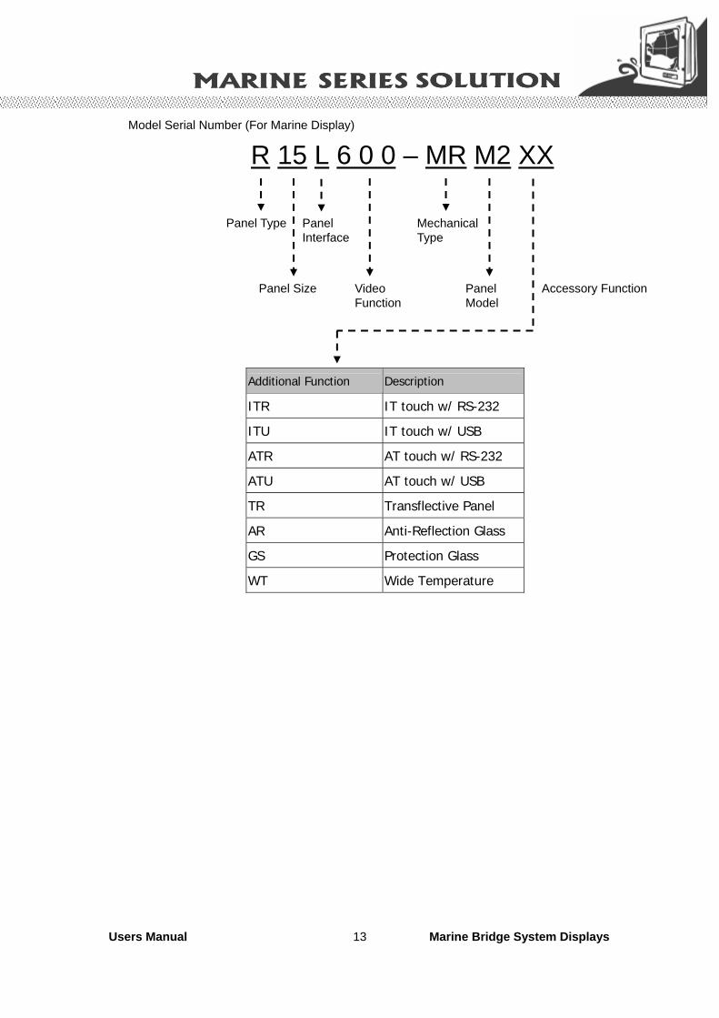
R 15 L 6 0 0 – MR M2 XX
Panel Type
Panel Size
Panel Interface
Video Function
Mechanical Type
Panel Model
Accessory Function
Additional Function Description
ITR IT touch w/ RS-232
ITU IT touch w/ USB
ATR AT touch w/ RS-232
ATU AT touch w/ USB
TR Transflective Panel
AR Anti-Reflection Glass
GS Protection Glass
WT Wide Temperature
Model Serial Number (For Marine Display)

Users Manual Marine Bridge System Displays 14
CHAPTER 2 Installation

Users Manual Marine Bridge System Displays 15
Chapter 2 Installation
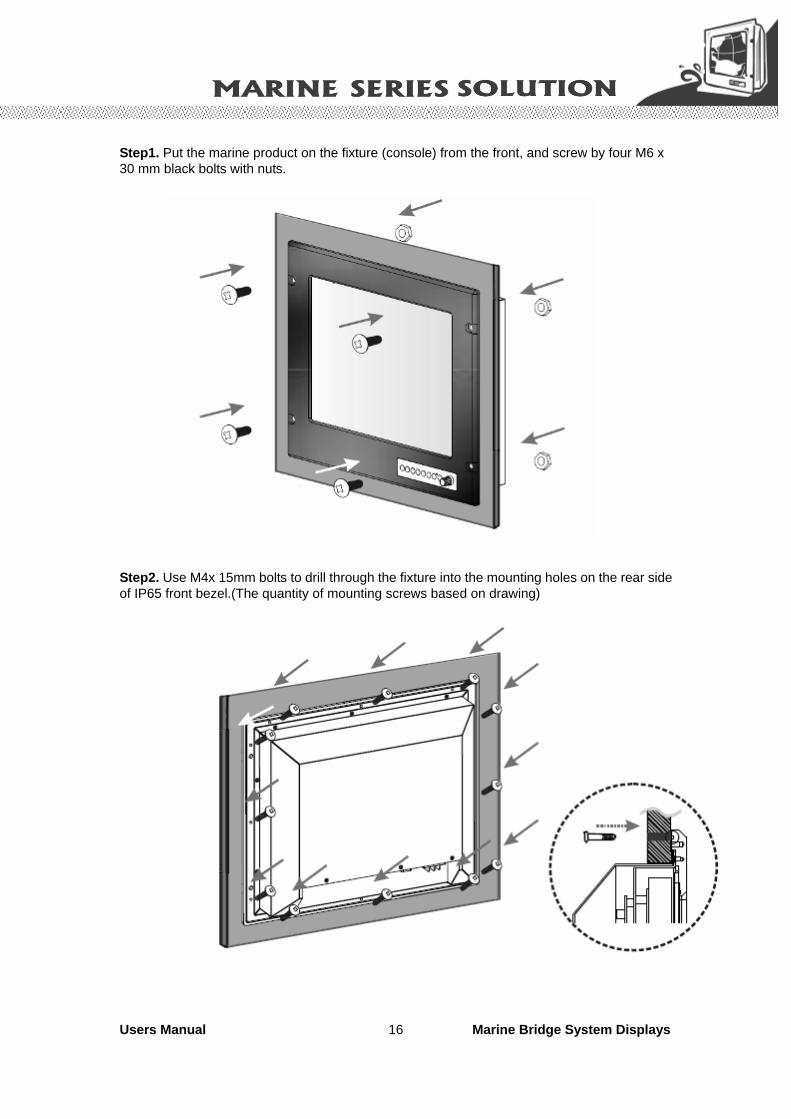
2.1 General installation The Marine Bridge System Display can be applied for several different installation methods. Including panel (flush) mounting, bracket mounting, ceiling / wall mounting…etc. For panel (flush) mounting is normally for a ship’s wheelhouse use, it’s easy to follow few steps to fix the display product in customer’s fixture. Check the mechanical and mounting concept as below first. The fixture cut-out dimension and mounting holes based on drawing.
Users Manual Marine Bridge System Displays 16
Step1. Put the marine product on the fixture (console) from the front, and screw by four M6 x 30 mm black bolts with nuts.
Step2. Use M4x 15mm bolts to drill through the fixture into the mounting holes on the rear side of IP65 front bezel.(The quantity of mounting screws based on drawing)

Users Manual Marine Bridge System Displays 17
Step3. Check the finished mounting concept. (DNV certification approved)
** Please Note: VESA and wall mount with mounting kit by special request.

Users Manual Marine Bridge System Displays 18
2.2 Installation Notice 2.2.1 Brightness Control Knob Precaution The dimming brightness control knob may be damaged by wrong placement. Please make sure the right way to protect the knob.
2.2.2 Cable Connection Precaution Make sure to use qualified shielded signal cable to connect to Marine products. These cables including RGB, DVI, RS232, LAN, and USB cable should be connected inside the area as marked below. For DC power connection, please make sure the power cable is tightly connected by two screws of the terminal block.

Users Manual Marine Bridge System Displays 19
CHAPTER 3 Operation the LCD Display
Users Manual Marine Bridge System Displays 20
Chapter 3 Operation of the LCD Display
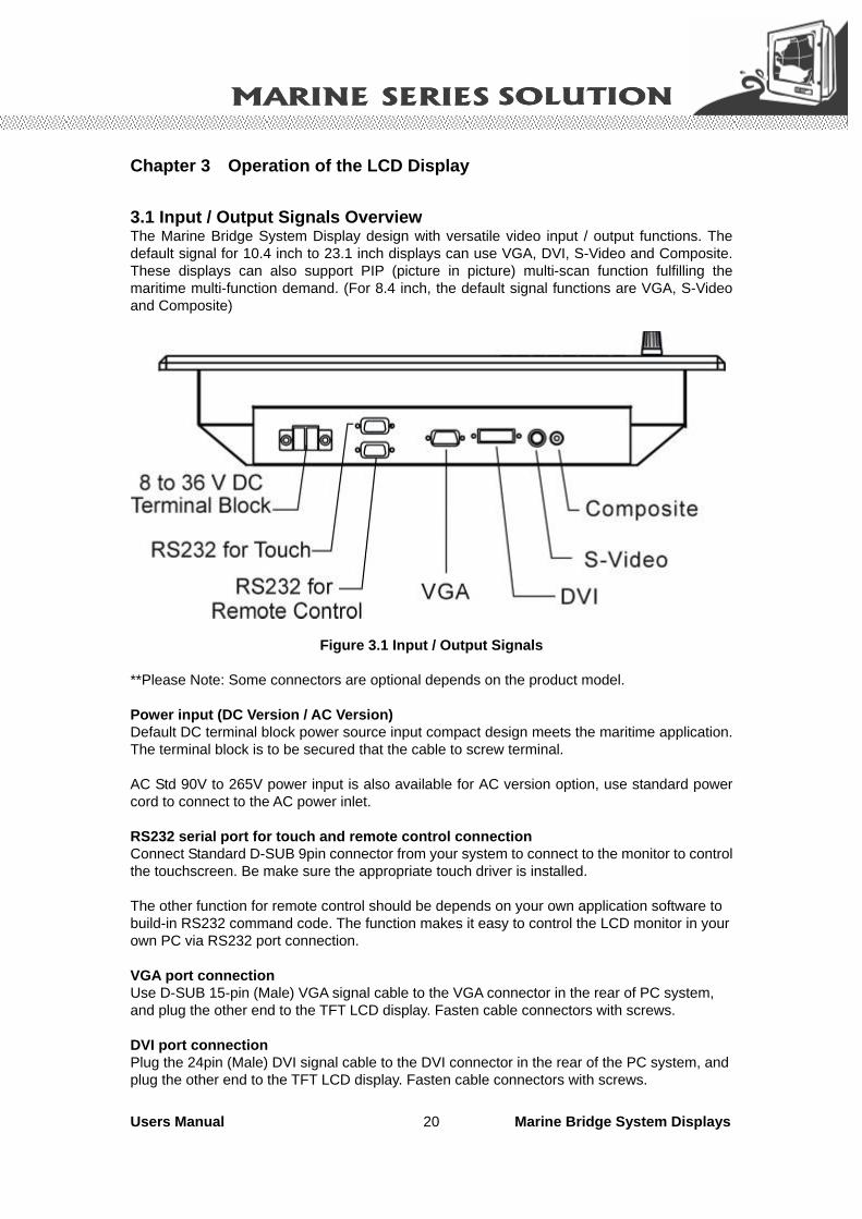
3.1 Input / Output Signals Overview The Marine Bridge System Display design with versatile video input / output functions. The default signal for 10.4 inch to 23.1 inch displays can use VGA, DVI, S-Video and Composite. These displays can also support PIP (picture in picture) multi-scan function fulfilling the maritime multi-function demand. (For 8.4 inch, the default signal functions are VGA, S-Video and Composite)
Figure 3.1 Input / Output Signals
**Please Note: Some connectors are optional depends on the product model. Power input (DC Version / AC Version) Default DC terminal block power source input compact design meets the maritime application. The terminal block is to be secured that the cable to screw terminal. AC Std 90V to 265V power input is also available for AC version option, use standard power cord to connect to the AC power inlet. RS232 serial port for touch and remote control connection Connect Standard D-SUB 9pin connector from your system to connect to the monitor to control the touchscreen. Be make sure the appropriate touch driver is installed. The other function for remote control should be depends on your own application software to build-in RS232 command code. The function makes it easy to control the LCD monitor in your own PC via RS232 port connection. VGA port connection Use D-SUB 15-pin (Male) VGA signal cable to the VGA connector in the rear of PC system, and plug the other end to the TFT LCD display. Fasten cable connectors with screws. DVI port connection Plug the 24pin (Male) DVI signal cable to the DVI connector in the rear of the PC system, and plug the other end to the TFT LCD display. Fasten cable connectors with screws.

Users Manual Marine Bridge System Displays 21
S-Video connection Plug standard S-Video(SVHS) cable into the mini 4 way din plug. Use PIP (picture in picture) function to switch source when multi video signals are activated and choose from OSD menu. * Note: The S-Video function must be activate by OSD menu selection. Composite connection Connect composite video signal cable into the RCA jack input. Use PIP (picture in picture) function to switch source when multi video signals are activated and choose from OSD menu. * Note: The Composite function must be activate by OSD menu selection.

Users Manual Marine Bridge System Displays 22
3.2 OSD User Controls The compact OSD in front control is a user-friendly interface both to remote the display function and dimming VR knob. The on screen display (OSD) contains several functions that will let the user to adjust or set up the display to their preferred setting. It also supplies special Hot Keys of clicking two keys together for easy flipping image and auto adjusting color balance
Figure 3.2 OSD User Controls .
The Dimming Knob The TFT LCD display support hyper dimming function to adjust brightness from nearly 0% to 100% via a easy to use VR knob. Power On/ Off
Press the Power On/Off button to switch the TFT LCD display power.
Display Status LED indicator When the TFT LCD display are normally operated, the LED indicator turns to green light. And the LED turns to red light when the TFT LCD display going to sleep.
Refer to the OSD Single Key Function as below and understand how to use the display functions step by step.
Single Key Function
AUTO MENU SOURCEPIP

Users Manual Marine Bridge System Displays 23
3.3 PIP (Picture in Picture) Function When OSD Menu is disabled, it cycles through the available PIP display modes. Repeated keystrokes will change the size of the PIP display to side-by-side (PAP) display, and then back to normal display.
When OSD Menu is enabled, press“ ” returns to the previous menu level or closes the OSD if pressed at the Menu level. 3.4 Auto Adjustment Function
When OSD Menu and PIP is disabled, press“ ” will perform the screen Auto Adjustment. When PIP is enabled, it switches the image in the Main Display to the PIP Display and vice versa by pressing again. When image side-by-side (PAP mode) is active, the SWAP key
( ) exchanges the left and right displays.

Users Manual Marine Bridge System Displays 24
3.5 Source Function
When OSD Menu is disabled, press “ ” will cycle through the available input sources for the Main Display. When OSD Menu is enabled, it moves right when navigating the Menu and Sub Menu and increments a slider bar.
press
press
press
press
press

Users Manual Marine Bridge System Displays 25
3.6 OSD Menu Function
After the power on, press” ” to enter OSD Menu.
Figure 3.3 OSD Menu
There are 9 functions for in the OSD Menu for selection. For each function, it is very easy to select by the other navigation keys to adjust. Following the direction as below:
1. Press “ ” (Up) and “ ” (Down) to select each function.
2. Press “ ” to enter the sub menu, and press “ ” to exit.
3. Press “ ” (Up) and “ ” (Down) to select the sub-function.
4. When enter to each sub-function, press “ ” (Left) and “ ” (Right) to decrease / increase the bar value.

Users Manual Marine Bridge System Displays 26
3.6.1 Display Item Menu
Figure 3.4 Display Item Menu
Display Item Menu
Menu Input Source Description and Usage
Brightness Adjust brightness only used in brightness knob. Adjustment is no response here.
Contrast
VGA DVI Composite S-Video Press “ ” / “ ” to adjust contrast.
Users Manual Marine Bridge System Displays 27
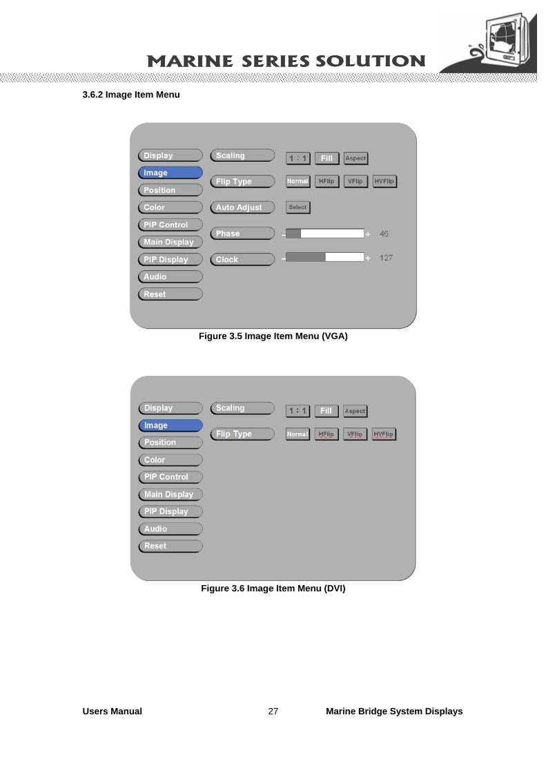
3.6.2 Image Item Menu
Figure 3.5 Image Item Menu (VGA)
Figure 3.6 Image Item Menu (DVI)

Users Manual Marine Bridge System Displays 28
Figure 3.7 Image Item Menu (Composite, S-Video)
Image Item Menu Menu Input Source Description and Usage
Scaling** Change the scaling mode by using the“ ” / “ ”
buttons to select 1:1, Fill or aspect. Press “ “ to activate the selected Scaling mode.
Flip Type
VGA DVI Composite S-Video Using “ ” / “ ” and “ “ to select the display flip for
Normal, HFlip, VFlip, or HVFlip mode.
Auto-Adjust** Initiate this to have the monitor logic to choose the best
settings for the current input signal.
Phase Adjust Phase to optimize the display quality by using
“ ” / “ ” to change the value.
Clock
VGA Only
Select Clock to adjust the horizontal screen size by
using “ ” / “ ” to change the value.
Hue Press “ ” / “ ” to select Hue to obtain the desired color settings.
Saturation Press “ ” / “” to select Saturation to adjust the optimal color degree level.
Noise Reduction Using “ ” / “ ” and “ “ to select the Noise Reduction for Off, Low, Mid, and High mode.
Sharpness
Composite and S-Video Only
The Sharpness of the image may be optimized by using
“ ” / “ ” to change the value of the slider bar.

Users Manual Marine Bridge System Displays 29
** Please Note in Scaling: 1. In 1:1 mode, the input image is centered on the screen. In Fill mode, the input image is
stretched / compressed to fill the available display area. 2. In Aspect mode, the input image is stretched / compressed by the same horizontal and vertical factor. ** Please Note in Auto-Adjust: The only button available is “SELECT”. Note this may change the values of Phase and Clock, and there is no ‘undo’ feature.

Users Manual Marine Bridge System Displays 30
3.6.3 Position Item Menu
Figure 3.8 Position Item Menu (VGA)
Figure 3.9 Position Item Menu (DVI, Composite, S-Video)

Users Manual Marine Bridge System Displays 31
Position Item Menu Menu Input Source Description and Usage
Zoom
Change the current Zoom setting only to the Main Display, using
“ ” / “ ” to select either In or Out. Zoom is at a temporary setting and will be lost at power down.
Zoom Horizontal
Zoom Horizontal is unavailable until the user performs a Zoom
In action. Using “ ” / “ ” to select either Left or Right to change the current Horizontal Pan setting. Pan settings will be
lost at power down.
Zoom Vertical
VGA DVI Composite S-Video
Zoom Vertical is unavailable until the user performs a Zoom In
action. Using “ ” / “ ” to select either Up or Down to change the current Vertical Pan setting and. Pan settings will be lost at
power down.
Vertical Move the screen up or down by using “ ” / “ ” to change the vertical position value.
Horizontal
VGA Move the screen left or right by using “ ” / “ ” to change the horizontal position value.
Users Manual Marine Bridge System Displays 32
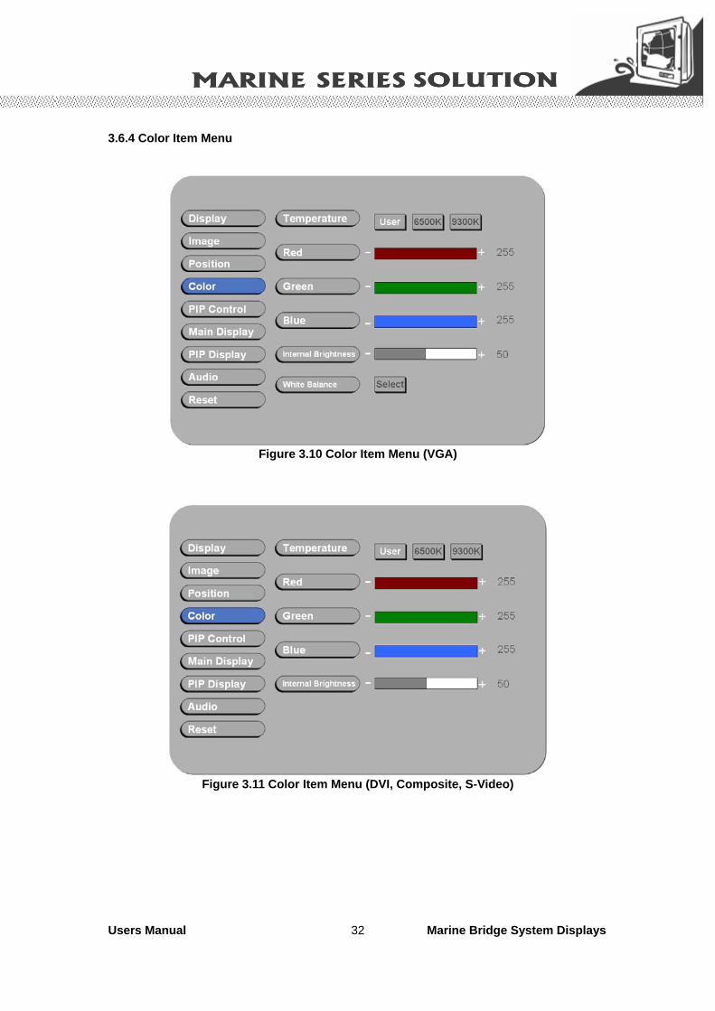
3.6.4 Color Item Menu
Figure 3.10 Color Item Menu (VGA)
Figure 3.11 Color Item Menu (DVI, Composite, S-Video)

Users Manual Marine Bridge System Displays 33
Color Item Menu Menu Input Source Description and Usage
Temperature
To configure color temperature, use “ ” / “ ” to change the value to User Preset, 6500K, or 9300 K to set a color
temperature to suit your own preference. When User Preset
is selected, the values of the Red, Green, and Blue sliders
below are used to determine color settings.
R Press “ ” / “ ” to adjust the Red color to obtain the desired color settings.
G Press “ ” / “ ” to adjust the Green color to obtain the desired color settings.
B Press “ ” / “ ” to adjust the Blue color to obtain the desired color settings.
Internal Brightness
VGA DVI Composite S-Video
Press “ ” / “ ” to adjust the Red color to obtain the desired color settings.
White Balance VGA Only
When in “VGA” mode, press “Select” to adjust White Balance
for the display setting.

Users Manual Marine Bridge System Displays 34
3.6.5 PIP Control Item Menu
Figure 3.12 PIP Control Item Menu
PIP Control Item Menu Menu Input Source Description and Usage
Mode
Use “ ” / “ ” to change the Mode value to be Off, Single, or PAP**.
In Off mode, the Main display fills the entire screen.
In Single mode, a PIP display floats over the screen.
In PAP mode, the screen is divided into two side-by-side display
areas.
Size
PIP Size can be altered only when Single PIP mode is selected.
To configure the PIP display size, use “ ” / “ ” to change the value to Small, Medium or Large.
Vertical**
Horizontal
VGA DVI Composite S-Video
Both vertical and horizontal PIP position can be altered only
when Single PIP mode is selected. Configure the PIP Vertical
and Horizontal Position, by using “ ” / “ ” to change the value using the slider bar.
** Please Note in PAP mode: When selecting “PAP” mode, the display area is now divided into two parts. The left window displays the Main output, while the right window displays the PIP output. Each window is half size of the total display area. Each input is scaled down to fit the window. ** Please Note in PIP mode: Note that the PIP screen can have any position on the screen. This can be achieved by adjusting both Horizontal and Vertical positions.

Users Manual Marine Bridge System Displays 35
3.6.6 Main Display Item Menu
Figure 3.13 Main Display Item Menu
Press “ ” and “ ” to select the Main Display main source, including VGA, DVI, Composite, and S-Video mode.
Press “ ” to choose “Select”.
Users Manual Marine Bridge System Displays 36
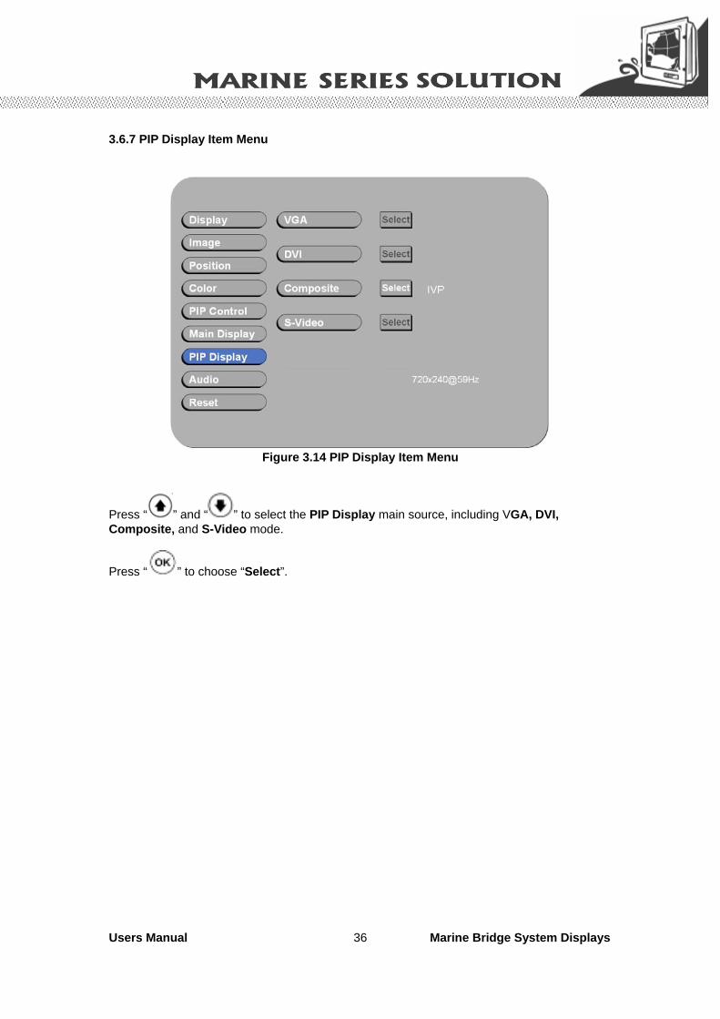
3.6.7 PIP Display Item Menu
Figure 3.14 PIP Display Item Menu
Press “ ” and “ ” to select the PIP Display main source, including VGA, DVI, Composite, and S-Video mode.
Press “ ” to choose “Select”.

Users Manual Marine Bridge System Displays 37
3.6.8 Audio Item Menu (Optional)
Figure 3.15 Audio Item Menu
Audio Item Menu Menu Input Source Description and Usage
Volume To adjust the volume, use “ ” / “ ” to change the value of the slider bar to increase or decrease the volume.
Balance To configure the audio balance, either left or right, use “ ” / “ ” to change the value of the slider bar to change the value.
Treble Increase or decrease the audio treble by using “ ” / “ ” to change the value.
Bass To configure the bass, use “ ” / “ ” to change the bass value.
Mute
VGA DVI Composite S-Video
To turn mute off/on, select either On/Off for Mute. By default, mute
is set to No, or turned off.

Users Manual Marine Bridge System Displays 38
3.6.9 Reset Item Menu
Figure 3.16 Reset Item Menu
Factory Reset Item Menu Menu Input Source Description and Usage
Factory Reset
VGA DVI Composite S-Video
To reset all settings to factory defaults, open the Factory Reset
Item. Use “ ” / “ ” to select the “Yes” option, and press “ ”.
WARNING: All user adjustments will be lost. Press “EXIT“ ( )to return to the Main Menu without making changes.
3.7 Simply trouble shooting guide What if the display has no power after you push the power button?
- First of all, make sure your power resource is work and your power cord is
securely connected into the plug-in. Second, if you have the power switch
button, please check the switch is “open”. After you check all of your power
connection and switch, please push the power button again to use your
product. What if the OSD (on screen display) controls is inaccessible?
- To unlock the OSD controls when the OSD is preset to be locked. What if there are strange lines on my LCD monitor when I shut down the PC?
- You can use the auto-adjust function to adjust the horizontal or vertical phase
and pixel frequency in order to solve this kind of problem. What if my LCD monitor screen keeps blinking?
- Please check you’re VGA or DVI connector to make sure the connector is
connecting well. Furthermore, you may also check your pins of the connector to
see if there are any bent or missing pins. For more information, please go on the website of http://www.winmate.com.tw/inquiry.htm to
ask your question. We will be pleasure to answer your questions.
Users Manual Marine Bridge System Displays 39
Appendix

Users Manual Marine Bridge System Displays 40
Appendix A: Cleaning the Monitor
1. Make sure the monitor is turned off. 2. Never spray or pour any liquid directly on the screen or case. 3. Wipe the screen with a clean, soft, lint-free cloth. This removes dust and other particles. 4. The display area is highly prone to scratching. Do not use ketone type material (ex. Acetone), Ethyl alcohol, toluene, ethyl acid or Methyl chloride to clear the panel. It may permanently damage the panel and void the warranty. 5. If it is still not clean enough, apply a small amount of non-ammonia, non-alcohol based glass cleaner onto a clean, soft, lint-free cloth, and wipe the screen. 6. Don’t use water or oil directly on the monitor. If droplets are allowed to drop on the monitor permanent staining or discoloration may occur.

Users Manual Marine Bridge System Displays 41
Appendix B: Disclaimer and Troubleshooting
Disclaimer We do not recommend using any ammonia or alcohol-based cleaners on the monitor screen or case. Some chemical cleaners have been reported to damage the screen and/or case of the monitor. Seller will not be liable for damage resulting from the use of any ammonia or alcohol-based cleaner. Troubleshooting If your monitor fails to operate correctly, consult the following chart for possible solution before calling for repairs: Condition Check Point The picture does not appear
Check if the signal cable is firmly seated in the socket. Check if the Power is ON at the computer Check if the brightness control is at the appropriate position, not at the minimum.
The screen is not synchronized
Check if the signal cable is firmly seated in the socket. Check if the output level matches the input level of your computer. Make sure the signal timings of the computer system are within the specification of the monitor. If your computer was working with a CRT monitor, you should check the current signal timing and turn off your computer before you connect the VGA Cable to this monitor.
The position of the screen is not in the center
Adjust the H-position, and V-position, or Perform the Auto adjustment.
The screen is too bright (too dark).
Check if the brightness or contrast control is at the appropriate position, not at the Maximum (Minimum).
The screen is shaking or waving
Perform the Auto adjustment.. Moving all objects which emit a magnetic field such as motor or transformer, away from the monitor. Check if the specific voltage is applied. Check if the signal timing of the computer system is within the specification of monitor.
If you are unable to correct the fault by using this chart, stop using your monitor and contact your distributor or dealer for further assistance.

Users Manual Marine Bridge System Displays 42
Appendix C: Supported Modes
Graphics No. Resolution Frequency (Hz) Note 1 640x350 70 IBM 2 640x400 70 IBM 3 640x480 60 VESA 4 640x480 72 VESA 5 640x480 75 VESA 6 720x400 70 IBM 7 800x600 56 VESA 8 800x600 60 VESA 9 800x600 72 VESA 10 800x600 75 VESA 11 1024x768 60 VESA 12 1024x768 70 VESA 13 1024x768 75 VESA 14 1280x768 60 15 1152x864 75 16 1280x960 60 VESA 17 1280x1024 60 VESA 18 1280x1024 60 HP 19 1280x1024 70 NCD 20 1280x1024 72 HP 21 1280x1024 75 VESA 22 1600x1200 60 VESA 23 1920x1200 60 VESA 24 1360x768 60
Video No. 1 NTSC / 480I / 525I 720 x 240 x 60I 2 PAL / 576I /625I 720 x 288 x 50I 3 480P 720 x 480 x 60P 4 (HDTV) 720P 1280 x 720 x 50P 5 (HDTV) 720P 1280 x 720 x 60P 6 (HDTV) 1080I 1920 x 1080 x 50I 7 (HDTV) 1080P 1920 x 1080 x 60I
Not all modes will be supported, due to different panel brands

Users Manual Marine Bridge System Displays 43
Appendix D: RS-232 Command Code(Optional)
01 DOWN 0x04, 0x12, 0x02, 0xE8, 0x00 02 UP 0x04, 0x12, 0x03, 0xE7, 0x00 03 LEFT 0x04, 0x12, 0x05, 0xE5, 0x00 04 RIGHT 0x04, 0x12, 0x06, 0xE4, 0x00 05 ENTER 0x04, 0x12, 0x07, 0xE3, 0x00 06 EXIT 0x04, 0x12, 0x08, 0xE2, 0x00 07 SWAP 0x04, 0x12, 0x0A, 0xE0, 0x00 08 SOURCE 0x04, 0x12, 0x0E, 0xDC, 0x00 09 POWER 0x04, 0x12, 0x0F, 0xDB, 0x00 10 AUTO ADJUST 0x04, 0x12, 0x11, 0xD9, 0x00 11 ASPECT 0x04, 0x12, 0x14, 0xD6, 0x00 12 MENU 0x04, 0x12, 0x15, 0xD5, 0x00 13 PIP 0x04, 0x12, 0x16, 0xD4, 0x00 14 VolDown 0x04, 0x12, 0x19, 0xD1, 0x00 15 VolUp 0x04, 0x12, 0x1A, 0xD0, 0x00 16 RESET 0x04, 0x12, 0x23, 0xC7, 0x00 17 AUTO COLOR 0x04, 0x12, 0x29, 0xC1, 0x00 18 FLIP 0x04, 0x12, 0x2C, 0xBE, 0x00 19 MUTE 0x04, 0x12, 0x2D, 0xBD, 0x00 20 ACK 0x03, 0x0C, 0xF1 Description: ex. DOWN 0x04, 0x12, 0x02, 0xE8, Function par1, par2, par3, par4 Function: DOWN down key Par1: 0x04 length (cannot be modified by user) Par2: 0x12 inquiry code (cannot be modified by user) Par3: 0x02 command code (can be modified by user) Par4: 0xE8 check sum (cannot be modified by user)

Users Manual Marine Bridge System Displays 44
Appendix E: Sunlight Readable (Transflective) Outdoor Readability (Optional)
Transflective LCD technology can be applied to certain selected regular TFT LCD to introduce the LCD with a reflective function. With the imposed reflective function, the modified LCD can reflect the ambient light passing the LCD cell and utilize the reflected light beams as its illumination. The stronger the ambient light is, the brighter the LCD will appear. As a result, the modified LCD is viewable under lighting conditions including direct sunlight.
The following table shows the outdoor readability for the Marine Bridge System Display models. Outdoor Readability
Model Number R08T200-MRT1TR
R10L100-MRM2TR
R15T600-MRA1TR
R17L500-MRA2TR
R19L300-MRA1TR
R20L100-MRA2TR
10,000 10,000 10,000 10,000 10,000 10,000
30,000 30,000 30,000 30,000 30,000 30,000
80,000 80,000 80,000 80,000 80,000 80,000
432.7 437.5 680 490 500 312.5
620 670 870 630 630 456
1,180 1,150 1,320 900 830 680
1.20% 1.20% 1% 0.83% 0.50% 0.70%
1.15% 1.15% 0.98% 0.70% 0.65% 0.68%
1.16% 1.10% 0.90% 0.45% 0.40% 0.45%
Ambient light(nit)
Brightness gain (nit)
Reflectance(net)(%)