marine radar - busse yachtshop · marine radar model 1835 model 1935 model 1945 operator's...
TRANSCRIPT
MARINE RADAR
MODEL 1835MODEL 1935MODEL 1945
OPERATOR'S MANUAL
www.furuno.co.jp
MODEL
www.busse-yachtshop.de | [email protected]
i
IMPORTANT NOTICES
General• The operator of this equipment must read and follow the descriptions in this manual. Wrong op-
eration or maintenance can cancel the warranty or cause injury.• Do not copy any part of this manual without written permission from FURUNO.• If this manual is lost or worn, contact your dealer about replacement.• The contents of this manual and equipment specifications can change without notice.• The example screens (or illustrations) shown in this manual can be different from the screens
you see on your display. The screens you see depend on your system configuration and equip-ment settings.
• Save this manual for future reference.• Any modification of the equipment (including software) by persons not authorized by FURUNO
will cancel the warranty.• All brand and product names are trademarks, registered trademarks or service marks of their
respective holders.
How to discard this productDiscard this product according to local regulations for the disposal of industrial waste. For disposal in the USA, see the homepage of the Electronics Industries Alliance (http://www.eiae.org/) for the correct method of disposal.
How to discard a used batterySome FURUNO products have a battery(ies). To see if your product has a battery(ies), see the chapter on Maintenance. Follow the instructions below if a battery(ies) is used.
In the European Union
The crossed-out trash can symbol indicates that all types of batteries must not be discarded in standard trash, or at a trash site. Take the used batteries to a battery collection site according to your national legislation and the Batteries Directive 2006/66/EU.
In the USA
The Mobius loop symbol (three chasing arrows) indicates that Ni-Cd and lead-acid rechargeable batteries must be recycled. Take the used batteries to a battery collection site according to local laws.
In the other countries
There are no international standards for the battery recycle symbol. The number of symbols can increase when the other countries make their own recycle symbols in the future.
Cd
Ni-Cd Pb
www.busse-yachtshop.de | [email protected]

SAFETY INSTRUCTIONS
WARNINGRadio Frequency Radiation Hazard
The radar antenna sends the electromagnetic radio frequency (RF) energy. This energycan be dangerous to you, especially your eyes. Do not look at the radiator or near theantenna when the antenna is rotating.
The distances at which RF radiation levels of 100 W/m2 and 10 W/m2 exist are shown inthe table.
Note: If the antenna unit is installed at a close distance in front of the wheel house,prevent the transmission in that area to protect passengers and crew from microwaveradiation. Set the [Sector Blanks] in the [System] menu.
Model Distance to100 W/m2 point
WARNING Indicates a condition that can cause death or serious injury if not avoided.
CAUTION Indicates a condition that can cause minor or moderate injury if not avoided.
Warning, Caution Mandatory ActionProhibitive Action
Read these safety instructions before you operate the equipment.
Distance to10 W/m2 point
1835
1935
1945
Worst case 0.2 m
Worst case 2.2 m
Worst case 2.2 m
Worst case 2.4 m
Worst case 0.1 m
Worst case 0.2 m
iiwww.busse-yachtshop.de | [email protected]
SAFETY INSTRUCTIONS
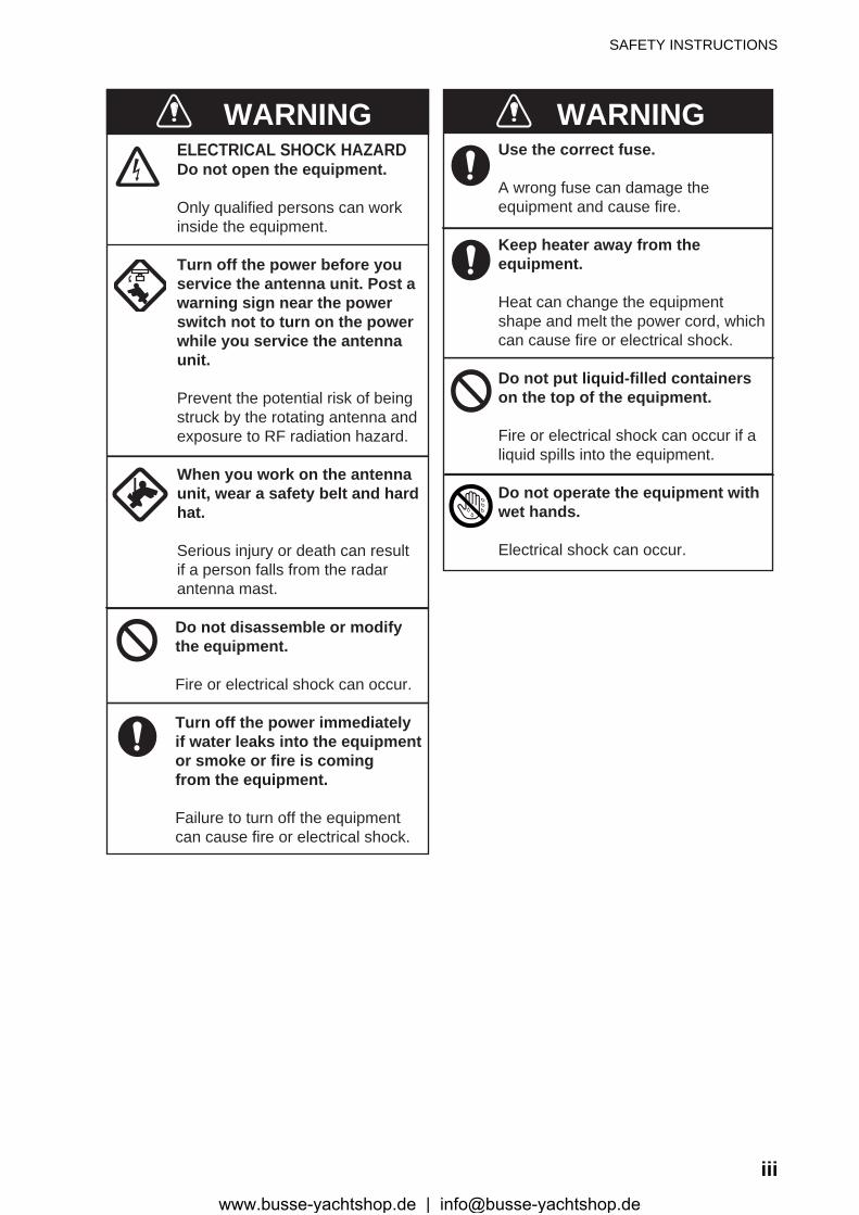
WARNINGELECTRICAL SHOCK HAZARDDo not open the equipment.
Only qualified persons can workinside the equipment.
Turn off the power before youservice the antenna unit. Post awarning sign near the powerswitch not to turn on the powerwhile you service the antennaunit.
Prevent the potential risk of beingstruck by the rotating antenna andexposure to RF radiation hazard.
When you work on the antennaunit, wear a safety belt and hardhat.
Serious injury or death can resultif a person falls from the radarantenna mast.
Do not disassemble or modifythe equipment.
Fire or electrical shock can occur.
Turn off the power immediatelyif water leaks into the equipmentor smoke or fire is comingfrom the equipment.
Failure to turn off the equipmentcan cause fire or electrical shock.
Use the correct fuse.
A wrong fuse can damage theequipment and cause fire.
Keep heater away from theequipment.
Heat can change the equipmentshape and melt the power cord, whichcan cause fire or electrical shock.
Do not put liquid-filled containerson the top of the equipment.
Fire or electrical shock can occur if aliquid spills into the equipment.
Do not operate the equipment withwet hands.
Electrical shock can occur.
WARNING
iiiwww.busse-yachtshop.de | [email protected]
SAFETY INSTRUCTIONS
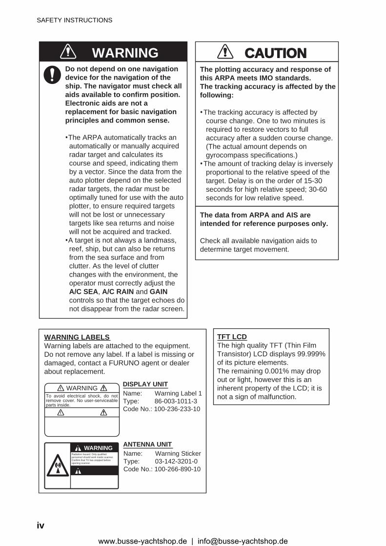
Do not depend on one navigationdevice for the navigation of theship. The navigator must check allaids available to confirm position.Electronic aids are not areplacement for basic navigationprinciples and common sense.
· The ARPA automatically tracks an automatically or manually acquired radar target and calculates its course and speed, indicating them by a vector. Since the data from the auto plotter depend on the selected radar targets, the radar must be optimally tuned for use with the auto plotter, to ensure required targets will not be lost or unnecessary targets like sea returns and noise will not be acquired and tracked.· A target is not always a landmass, reef, ship, but can also be returns from the sea surface and from clutter. As the level of clutter changes with the environment, the operator must correctly adjust the A/C SEA, A/C RAIN and GAIN controls so that the target echoes do not disappear from the radar screen.
CAUTIONCAUTIONThe plotting accuracy and response ofthis ARPA meets IMO standards.The tracking accuracy is affected by thefollowing:
· The tracking accuracy is affected by course change. One to two minutes is required to restore vectors to full accuracy after a sudden course change. (The actual amount depends on gyrocompass specifications.)· The amount of tracking delay is inversely proportional to the relative speed of the target. Delay is on the order of 15-30 seconds for high relative speed; 30-60 seconds for low relative speed.
The data from ARPA and AIS areintended for reference purposes only.
Check all available navigation aids to determine target movement.
WARNINGTo avoid electrical shock, do not remove cover. No user-serviceable parts inside.
WARNING LABELSWarning labels are attached to the equipment. Do not remove any label. If a label is missing or damaged, contact a FURUNO agent or dealerabout replacement.
WARNINGRadiation hazard. Only qualified personnel should work inside scanner.Confirm that TX has stopped beforeopening scanner.
DISPLAY UNIT
ANTENNA UNIT
TFT LCDThe high quality TFT (Thin FilmTransistor) LCD displays 99.999%of its picture elements.The remaining 0.001% may dropout or light, however this is aninherent property of the LCD; it isnot a sign of malfunction.
WARNING
Name: Warning Label 1Type: 86-003-1011-3Code No.: 100-236-233-10
Name: Warning StickerType: 03-142-3201-0Code No.: 100-266-890-10
ivwww.busse-yachtshop.de | [email protected]
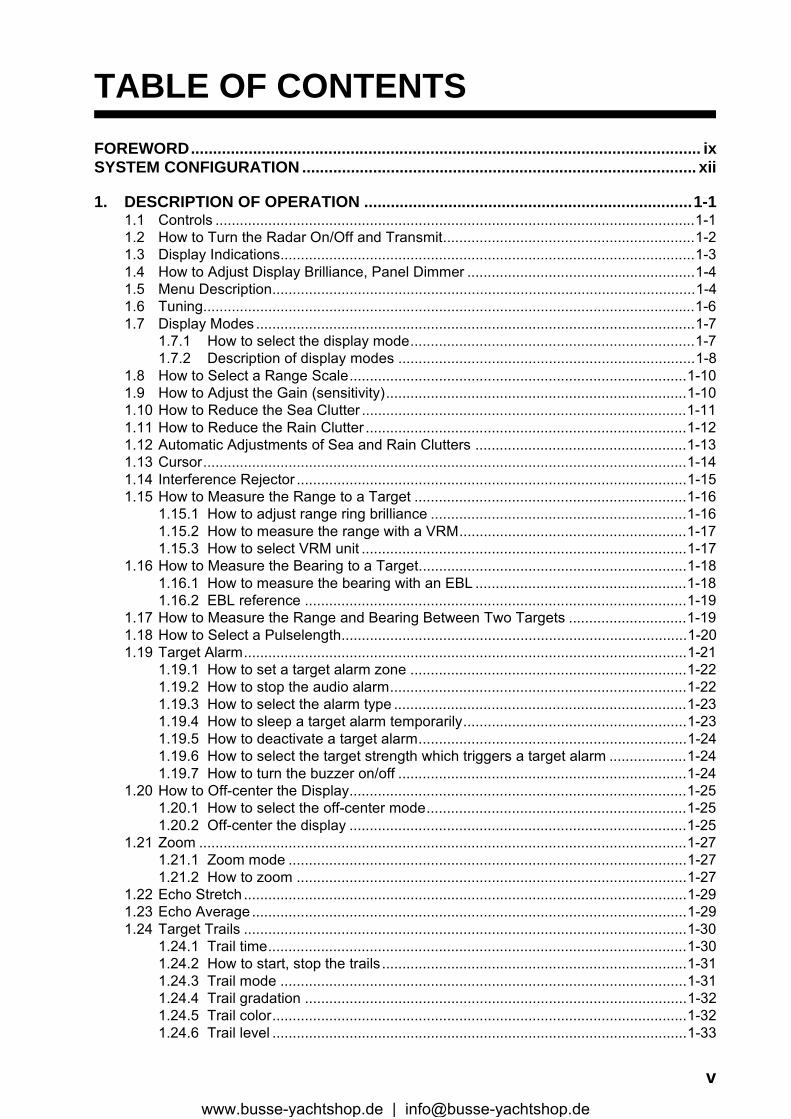
TABLE OF CONTENTS
FOREWORD................................................................................................................... ixSYSTEM CONFIGURATION ......................................................................................... xii1. DESCRIPTION OF OPERATION ..........................................................................1-11.1 Controls ......................................................................................................................1-11.2 How to Turn the Radar On/Off and Transmit..............................................................1-21.3 Display Indications......................................................................................................1-31.4 How to Adjust Display Brilliance, Panel Dimmer ........................................................1-41.5 Menu Description........................................................................................................1-41.6 Tuning.........................................................................................................................1-61.7 Display Modes ............................................................................................................1-7
1.7.1 How to select the display mode......................................................................1-71.7.2 Description of display modes .........................................................................1-8
1.8 How to Select a Range Scale...................................................................................1-101.9 How to Adjust the Gain (sensitivity)..........................................................................1-101.10 How to Reduce the Sea Clutter ................................................................................1-111.11 How to Reduce the Rain Clutter ...............................................................................1-121.12 Automatic Adjustments of Sea and Rain Clutters ....................................................1-131.13 Cursor.......................................................................................................................1-141.14 Interference Rejector ................................................................................................1-151.15 How to Measure the Range to a Target ...................................................................1-16
1.15.1 How to adjust range ring brilliance ...............................................................1-161.15.2 How to measure the range with a VRM........................................................1-171.15.3 How to select VRM unit ................................................................................1-17
1.16 How to Measure the Bearing to a Target..................................................................1-181.16.1 How to measure the bearing with an EBL ....................................................1-181.16.2 EBL reference ..............................................................................................1-19
1.17 How to Measure the Range and Bearing Between Two Targets .............................1-191.18 How to Select a Pulselength.....................................................................................1-201.19 Target Alarm.............................................................................................................1-21
1.19.1 How to set a target alarm zone ....................................................................1-221.19.2 How to stop the audio alarm.........................................................................1-221.19.3 How to select the alarm type ........................................................................1-231.19.4 How to sleep a target alarm temporarily.......................................................1-231.19.5 How to deactivate a target alarm..................................................................1-241.19.6 How to select the target strength which triggers a target alarm ...................1-241.19.7 How to turn the buzzer on/off .......................................................................1-24
1.20 How to Off-center the Display...................................................................................1-251.20.1 How to select the off-center mode................................................................1-251.20.2 Off-center the display ...................................................................................1-25
1.21 Zoom ........................................................................................................................1-271.21.1 Zoom mode ..................................................................................................1-271.21.2 How to zoom ................................................................................................1-27
1.22 Echo Stretch .............................................................................................................1-291.23 Echo Average ...........................................................................................................1-291.24 Target Trails .............................................................................................................1-30
1.24.1 Trail time.......................................................................................................1-301.24.2 How to start, stop the trails ...........................................................................1-311.24.3 Trail mode ....................................................................................................1-311.24.4 Trail gradation ..............................................................................................1-321.24.5 Trail color......................................................................................................1-321.24.6 Trail level ......................................................................................................1-33
vwww.busse-yachtshop.de | [email protected]
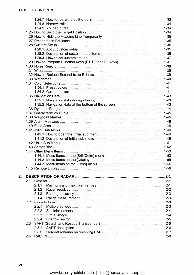
TABLE OF CONTENTS
1.24.7 How to restart, stop the trails ....................................................................... 1-331.24.8 Narrow trails ................................................................................................. 1-341.24.9 Your ship trail ............................................................................................... 1-34
1.25 How to Send the Target Position ............................................................................. 1-341.26 How to Hide the Heading Line Temporarily ............................................................. 1-351.27 Presentation Brilliance ............................................................................................. 1-351.28 Custom Setup .......................................................................................................... 1-35
1.28.1 About custom setup ..................................................................................... 1-351.28.2 Description of custom setup items ............................................................... 1-361.28.3 How to set custom setups............................................................................ 1-37
1.29 How to Program Function Keys (F1, F2 and F3 keys) ............................................. 1-371.30 Noise Rejector.......................................................................................................... 1-381.31 Wiper........................................................................................................................ 1-391.32 How to Reduce Second-trace Echoes ..................................................................... 1-391.33 Watchman ................................................................................................................ 1-401.34 Color Selections ....................................................................................................... 1-41
1.34.1 Preset colors ................................................................................................ 1-411.34.2 Custom colors .............................................................................................. 1-41
1.35 Navigation Data........................................................................................................ 1-431.35.1 Navigation data during standby.................................................................... 1-431.35.2 Navigation data at the bottom of the screen ................................................ 1-43
1.36 Dynamic Range........................................................................................................ 1-441.37 Characteristics Curve............................................................................................... 1-451.38 Waypoint Marker ...................................................................................................... 1-461.39 Alarm Message ........................................................................................................ 1-461.40 Echo Area ................................................................................................................ 1-481.41 Initial Sub Menu ....................................................................................................... 1-49
1.41.1 How to open the Initial sub menu................................................................. 1-491.41.2 Description of Initial sub menu..................................................................... 1-49
1.42 Units Sub Menu........................................................................................................ 1-511.43 Sector Blank............................................................................................................. 1-521.44 Other Menu Items .................................................................................................... 1-53
1.44.1 Menu items on the [Brill/Color] menu........................................................... 1-531.44.2 Menu items on the [Display] menu............................................................... 1-551.44.3 Menu items on the [Echo] menu .................................................................. 1-56
1.45 Remote Display........................................................................................................ 1-56
2. DESCRIPTION OF RADAR ...................................................................................2-12.1 General ...................................................................................................................... 2-1
2.1.1 Minimum and maximum ranges..................................................................... 2-12.1.2 Radar resolution............................................................................................. 2-22.1.3 Bearing accuracy ........................................................................................... 2-32.1.4 Range measurement...................................................................................... 2-3
2.2 False Echoes ............................................................................................................. 2-32.2.1 Multiple echoes .............................................................................................. 2-32.2.2 Sidelobe echoes............................................................................................. 2-42.2.3 Virtual image .................................................................................................. 2-42.2.4 Shadow sector ............................................................................................... 2-5
2.3 SART (Search and Rescue Transponder) ................................................................. 2-62.3.1 SART description ........................................................................................... 2-62.3.2 General remarks on receiving SART ............................................................. 2-7
2.4 RACON ...................................................................................................................... 2-8
viwww.busse-yachtshop.de | [email protected]

TABLE OF CONTENTS
3. ARPA OPERATION...............................................................................................3-13.1 Precautions for Use ....................................................................................................3-13.2 Controls for Use with ARPA .......................................................................................3-13.3 ARPA Display On/Off .................................................................................................3-23.4 How to Acquire and Track the Targets .......................................................................3-2
3.4.1 Manual acquisition..........................................................................................3-23.4.2 Automatic acquisition .....................................................................................3-3
3.5 How to Stop the Tracking of ARPA Target .................................................................3-33.5.1 How to stop the tracking of selected targets ..................................................3-33.5.2 How to stop the tracking of all targets ............................................................3-3
3.6 Vector Attributes .........................................................................................................3-43.6.1 What is a vector?............................................................................................3-43.6.2 Vector time and vector reference ...................................................................3-43.6.3 Vector of your ship .........................................................................................3-5
3.7 History Display (target past position)..........................................................................3-63.8 ARPA Target Data......................................................................................................3-73.9 CPA/TCPA Alarm .......................................................................................................3-83.10 Proximity Alarm ..........................................................................................................3-93.11 Lost Target ...............................................................................................................3-103.12 Symbol Color ............................................................................................................3-10
4. AIS OPERATION ...................................................................................................4-14.1 Controls for Use with AIS ...........................................................................................4-14.2 AIS Display On/Off .....................................................................................................4-14.3 AIS Symbols ...............................................................................................................4-24.4 Activating, Sleeping Targets.......................................................................................4-24.5 AIS Target Data..........................................................................................................4-34.6 How to Sort Targets....................................................................................................4-44.7 Display Range ............................................................................................................4-44.8 How to Display the Targets within a Specific Sector ..................................................4-54.9 Number of Targets to Display.....................................................................................4-54.10 Vector Attributes .........................................................................................................4-6
4.10.1 What is a vector?............................................................................................4-64.10.2 Vector time and vector reference ...................................................................4-6
4.11 History Display (target past position)..........................................................................4-74.12 CPA/TCPA Alarm .......................................................................................................4-84.13 Proximity Alarm ..........................................................................................................4-94.14 Lost Target .................................................................................................................4-94.15 Symbol Color ............................................................................................................4-104.16 How to Ignore Slow Targets .....................................................................................4-10
5. GPS OPERATION .................................................................................................5-15.1 Navigator Mode ..........................................................................................................5-15.2 Datum.........................................................................................................................5-15.3 WAAS Setup...............................................................................................................5-25.4 Satellite Monitor..........................................................................................................5-35.5 Cold Start....................................................................................................................5-4
6. MAINTENANCE, TROUBLESHOOTING ..............................................................6-16.1 Preventive Maintenance .............................................................................................6-26.2 Fuse Replacement .....................................................................................................6-36.3 Magnetron Life............................................................................................................6-36.4 LCD Backlight Life ......................................................................................................6-36.5 Simple Troubleshooting..............................................................................................6-46.6 Advanced-level Troubleshooting ................................................................................6-56.7 Diagnostic Test...........................................................................................................6-7
viiwww.busse-yachtshop.de | [email protected]

TABLE OF CONTENTS
6.8 LCD Test .................................................................................................................... 6-96.9 ARPA Test ............................................................................................................... 6-106.10 GPS Test.................................................................................................................. 6-11
APPENDIX 1 MENU TREE .......................................................................................AP-1APPENDIX 2 GEODETIC CHART LIST ...................................................................AP-5SPECIFICATIONS .....................................................................................................SP-1INDEX.......................................................................................................................... IN-1
viiiwww.busse-yachtshop.de | [email protected]
FOREWORD
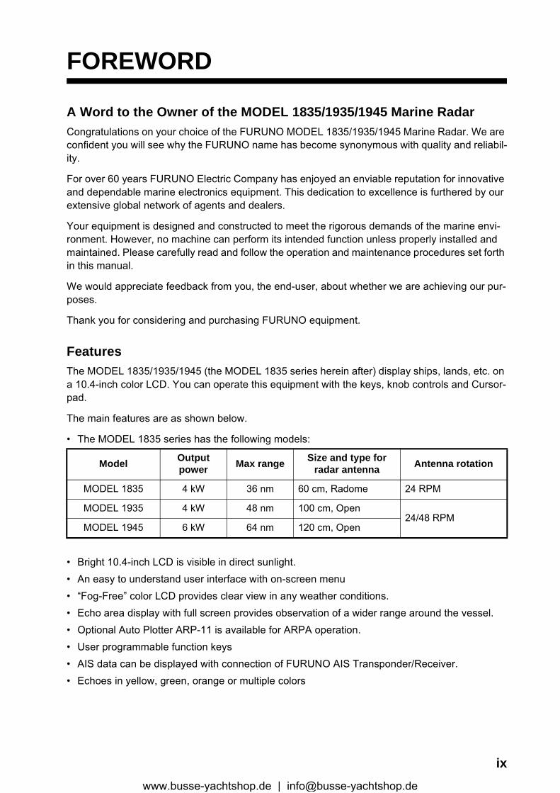
A Word to the Owner of the MODEL 1835/1935/1945 Marine RadarCongratulations on your choice of the FURUNO MODEL 1835/1935/1945 Marine Radar. We are confident you will see why the FURUNO name has become synonymous with quality and reliabil-ity.
For over 60 years FURUNO Electric Company has enjoyed an enviable reputation for innovative and dependable marine electronics equipment. This dedication to excellence is furthered by our extensive global network of agents and dealers.
Your equipment is designed and constructed to meet the rigorous demands of the marine envi-ronment. However, no machine can perform its intended function unless properly installed and maintained. Please carefully read and follow the operation and maintenance procedures set forth in this manual.
We would appreciate feedback from you, the end-user, about whether we are achieving our pur-poses.
Thank you for considering and purchasing FURUNO equipment.
FeaturesThe MODEL 1835/1935/1945 (the MODEL 1835 series herein after) display ships, lands, etc. on a 10.4-inch color LCD. You can operate this equipment with the keys, knob controls and Cursor-pad.
The main features are as shown below.
• The MODEL 1835 series has the following models:
• Bright 10.4-inch LCD is visible in direct sunlight.• An easy to understand user interface with on-screen menu• “Fog-Free” color LCD provides clear view in any weather conditions.• Echo area display with full screen provides observation of a wider range around the vessel.• Optional Auto Plotter ARP-11 is available for ARPA operation.• User programmable function keys• AIS data can be displayed with connection of FURUNO AIS Transponder/Receiver.• Echoes in yellow, green, orange or multiple colors
Model Output power Max range Size and type for
radar antenna Antenna rotation
MODEL 1835 4 kW 36 nm 60 cm, Radome 24 RPM
MODEL 1935 4 kW 48 nm 100 cm, Open24/48 RPM
MODEL 1945 6 kW 64 nm 120 cm, Open
ixwww.busse-yachtshop.de | [email protected]
FOREWORD
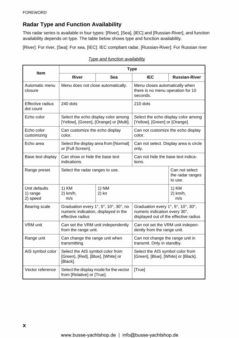
Radar Type and Function AvailabilityThis radar series is available in four types: [River], [Sea], [IEC] and [Russian-River], and function availability depends on type. The table below shows type and function availability.
[River]: For river, [Sea]: For sea, [IEC]: IEC compliant radar, [Russian-River]: For Russian river
Type and function availability
ItemType
River Sea IEC Russian-River
Automatic menu closure
Menu does not close automatically. Menu closes automatically when there is no menu operation for 10 seconds.
Effective radius dot count
240 dots 210 dots
Echo color Select the echo display color among [Yellow], [Green], [Orange] or [Multi].
Select the echo display color among [Yellow], [Green] or [Orange].
Echo colorcustomizing
Can customize the echo displaycolor.
Can not customize the echo display color.
Echo area Select the display area from [Normal] or [Full Screen].
Can not select. Display area is circle only.
Base text display Can show or hide the base textindications.
Can not hide the base text indica-tions.
Range preset Select the radar ranges to use. Can not select the radar ranges to use.
Unit defaults1) range2) speed
1) KM2) km/h, m/s
1) NM2) kn
1) KM2) km/h, m/s
Bearing scale Graduation every 1°, 5°, 10°, 30°, no numeric indication, displayed in the effective radius
Graduation every 1°, 5°, 10°, 30°,numeric indication every 30°,displayed out of the effective radius
VRM unit Can set the VRM unit independently from the range unit.
Can not set the VRM unit indepen-dently from the range unit.
Range unit Can change the range unit whentransmitting.
Can not change the range unit intransmit. Only in standby.
AIS symbol color Select the AIS symbol color from [Green], [Red], [Blue], [White] or [Black].
Select the AIS symbol color from [Green], [Blue], [White] or [Black].
Vector reference Select the display mode for the vector from [Relative] or [True].
[True]
xwww.busse-yachtshop.de | [email protected]
FOREWORD
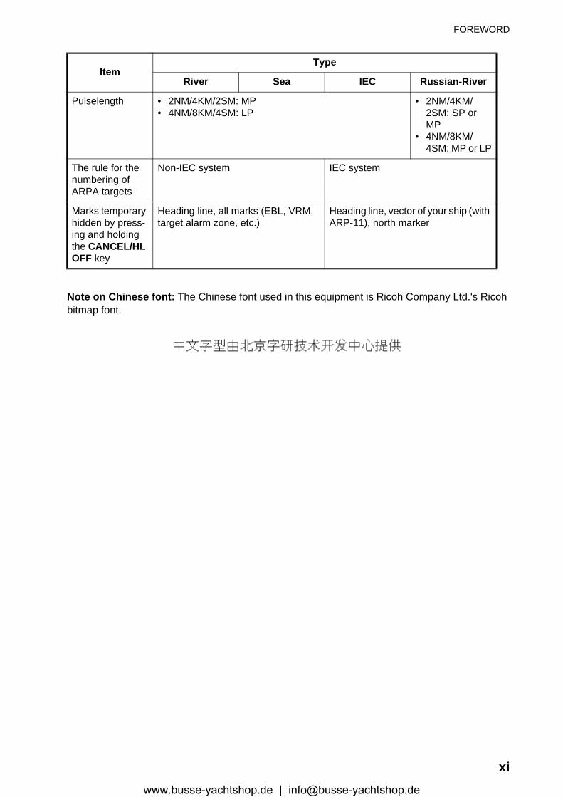
Note on Chinese font: The Chinese font used in this equipment is Ricoh Company Ltd.'s Ricoh bitmap font.
ItemType
River Sea IEC Russian-River
Pulselength • 2NM/4KM/2SM: MP• 4NM/8KM/4SM: LP
• 2NM/4KM/2SM: SP or MP
• 4NM/8KM/4SM: MP or LP
The rule for the numbering of ARPA targets
Non-IEC system IEC system
Marks temporary hidden by press-ing and holding the CANCEL/HL OFF key
Heading line, all marks (EBL, VRM, target alarm zone, etc.)
Heading line, vector of your ship (with ARP-11), north marker
xiwww.busse-yachtshop.de | [email protected]
x
S
B
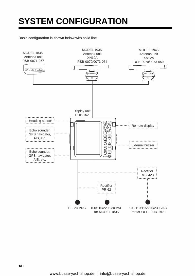
YSTEM CONFIGURATION
asic configuration is shown below with solid line.
12 - 24 VDC
Display unitRDP-152
100/110/220/230 VACfor MODEL 1835
External buzzer
Echo sounder,GPS navigator,
AIS, etc.
Remote displayHeading sensor
MODEL 1835 Antenna unit
RSB-0071-057
Echo sounder,GPS navigator,
AIS, etc.ECONOMY
RANGE
TLL
GAIN
TRAILS
OFFCENTER
TARGETALARM
STBYT X
A/C SEA
A/C RAIN
CUSTOM
MENUCANCEL
EBL VRM
HL OFF
ENTER
RB LLI
MODEL 1945Antenna unit
XN12ARSB-0070/0073-059
MODEL 1935 Antenna unit
XN10ARSB-0070/0073-064
RectifierPR-62
RectifierRU-3423
100/110/115/220/230 VACfor MODEL 1935/1945
iiwww.busse-yachtshop.de | [email protected]
1. DESCRIPTION OF OPERATION
1.1 ControlsDisplay unit
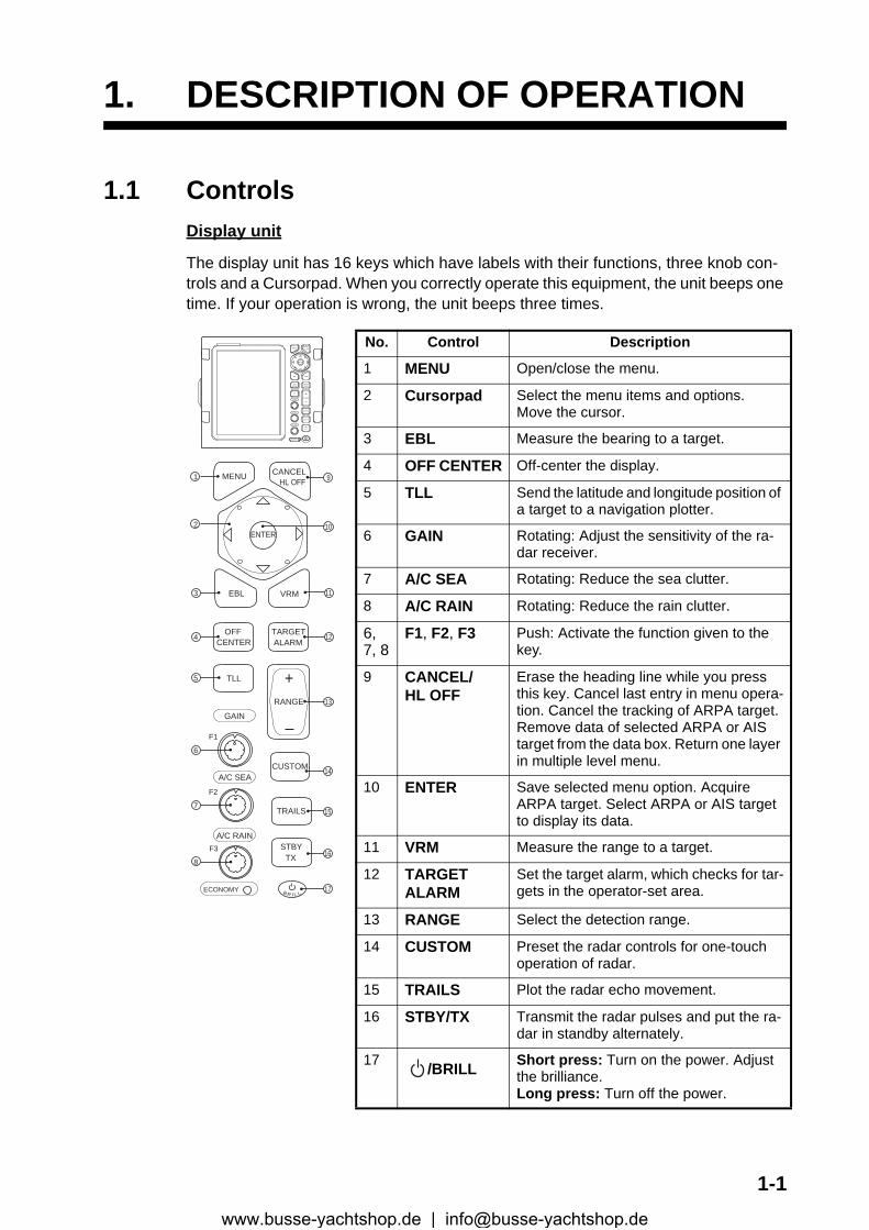
The display unit has 16 keys which have labels with their functions, three knob con-trols and a Cursorpad. When you correctly operate this equipment, the unit beeps one time. If your operation is wrong, the unit beeps three times.
No. Control Description
1 MENU Open/close the menu.
2 Cursorpad Select the menu items and options.Move the cursor.
3 EBL Measure the bearing to a target.
4 OFF CENTER Off-center the display.
5 TLL Send the latitude and longitude position of a target to a navigation plotter.
6 GAIN Rotating: Adjust the sensitivity of the ra-dar receiver.
7 A/C SEA Rotating: Reduce the sea clutter.
8 A/C RAIN Rotating: Reduce the rain clutter.
6, 7, 8
F1, F2, F3 Push: Activate the function given to the key.
9 CANCEL/HL OFF
Erase the heading line while you press this key. Cancel last entry in menu opera-tion. Cancel the tracking of ARPA target. Remove data of selected ARPA or AIS target from the data box. Return one layer in multiple level menu.
10 ENTER Save selected menu option. Acquire ARPA target. Select ARPA or AIS target to display its data.
11 VRM Measure the range to a target.
12 TARGETALARM
Set the target alarm, which checks for tar-gets in the operator-set area.
13 RANGE Select the detection range.
14 CUSTOM Preset the radar controls for one-touch operation of radar.
15 TRAILS Plot the radar echo movement.
16 STBY/TX Transmit the radar pulses and put the ra-dar in standby alternately.
17 /BRILL Short press: Turn on the power. Adjust the brilliance.Long press: Turn off the power.
MENU CANCELHL OFF
ENTER
EBL VRM
OFFCENTER
TARGETALARM
TLL
GAIN
A/C SEA
A/C RAIN
RANGE
+
CUSTOM
TRAILS
STBYTX
ECONOMY
F1
F2
F3
1
2
3
4
5
B R I L L
6
7
8
9
11
12
13
14
15
16
17
10
ECONOMY
RANGE
TLL
GAIN
TRAILS
OFFCENTER
TARGETALARM
STBYT X
A/C SEA
A/C RAIN
CUSTOM
MENUCANCEL
EBL VRM
HL OFF
ENTER
RB LLI
1-1www.busse-yachtshop.de | [email protected]
1. DESCRIPTION OF OPERATION
1.2 How to Turn the Radar On/Off and Transmit
Press the key to turn on the radar. To turn off the radar, press and hold down the key until the screen turns off.
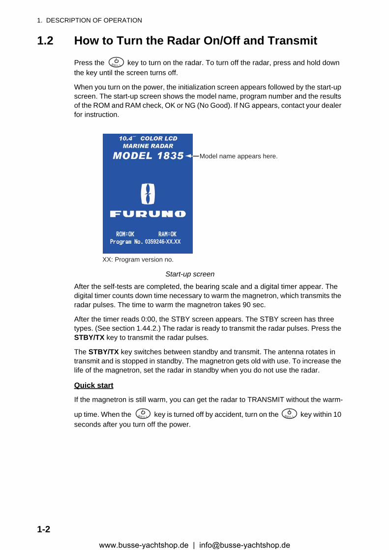
When you turn on the power, the initialization screen appears followed by the start-up screen. The start-up screen shows the model name, program number and the results of the ROM and RAM check, OK or NG (No Good). If NG appears, contact your dealer for instruction.
Start-up screen
After the self-tests are completed, the bearing scale and a digital timer appear. The digital timer counts down time necessary to warm the magnetron, which transmits the radar pulses. The time to warm the magnetron takes 90 sec.
After the timer reads 0:00, the STBY screen appears. The STBY screen has three types. (See section 1.44.2.) The radar is ready to transmit the radar pulses. Press the STBY/TX key to transmit the radar pulses.
The STBY/TX key switches between standby and transmit. The antenna rotates in transmit and is stopped in standby. The magnetron gets old with use. To increase the life of the magnetron, set the radar in standby when you do not use the radar.
Quick start
If the magnetron is still warm, you can get the radar to TRANSMIT without the warm-
up time. When the key is turned off by accident, turn on the key within 10 seconds after you turn off the power.
B R I L L
Model name appears here.
0359246-XX.XX
XX: Program version no.
B R I L L B R I L L
1-2www.busse-yachtshop.de | [email protected]
1. DESCRIPTION OF OPERATION
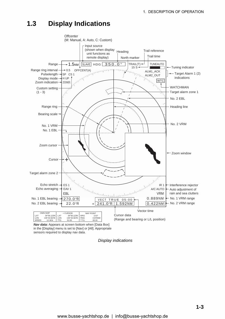
1.3 Display Indications
Display indications
Heading
Nav data: Appears at screen bottom when [Data Box]in the [Display] menu is set to [Nav] or [All]. Appropriatesensors required to display nav data.
Cursor data(Range and bearing or L/L position)
Display mode
Range ring interval
Range
Pulselength
Trail reference
No. 1 EBL bearingNo. 2 EBL bearing
Offcenter(M: Manual, A: Auto, C: Custom)
North marker
Tuning indicator
Target Alarm 1 (2)indications
No. 1 VRM rangeNo. 2 VRM range
WATCHMANTarget alarm zone 1
Target alarm zone 2
3 5 0 . 0 ° TRAIL(T)15 S
+
1.51.5NMNM
OFFCENT(A)
WTC
Heading lineRange ring
No. 2 VRM
No. 2 EBL
Zoom window
Zoom cursor
No. 1 EBLNo. 1 VRM
Cursor
Bearing scale
HDG
0.5SP CS 1
Custom setting(1 - 3)
H UP
LAT 34°56.123NLON 135°34.567ESPEED 12.3KN
LAT 34°56.123NLON 135°34.567ETTG 01:00
BRG 14.8°RNG 0.876NMTTG 00:20
OWN SHIP + CURSOR WAY POINT
TUNEAUTO
ALM1_ACKALM2_OUT
SLAVE
Input source(shown when display unit functions as remote display)
IR 1A/C AUTO
VRM0.889NM0.422NM
Interference rejectorAuto adjustment ofrain and sea clutters
22.0°R270.0°R
ES 1EAV 1
EBL
Echo stretchEcho averaging
241.0°R 1.592NMV E C T T R U E 0 5 : 0 0
Vector time
ZOOM(R) Zoom indication
+
Trail time
1-3www.busse-yachtshop.de | [email protected]

1. DESCRIPTION OF OPERATION
1.4 How to Adjust Display Brilliance, Panel DimmerYou can adjust the display brilliance and panel dimmer as follows:
1. Press the key momentarily to show the [Brill/Panel] dialog box.
Brill/Panel dialog box2. Press the ENTER key (or , ) to select [Brill] or [Panel].
3. Use the Cursorpad ( or ) to adjust. (For brilliance, you can also use the key.)
4. Press the CANCEL/HL OFF key to close the window.
1.5 Menu DescriptionThis MODEL 1835 series has 15 menus and 6 sub menus. Below is the basic proce-dure for menu operation.
1. Press the MENU key to open the menu.
Menu
B R I L L
B R I L L
Cursor*
Menu itemsand currentsettings
Currently selected menu
Scroll bar (Indicates menus currently not shown in menuwindow. Black vertical line indicates location in menu.You can see the menus and sub menus currently not shownby using � or �.)
Menu
Title bar*
Guide message(The simple explanation for the current menu.)
*: Title bar in currently controllable column is blue; selected cursor is yellow. Title bar of inactive column is gray.
1-4www.busse-yachtshop.de | [email protected]

1. DESCRIPTION OF OPERATION
2. Use the Cursorpad ( or ) to select a menu or a sub menu. The cursor (yellow) in the Menu column indicates the menu currently selected. The menu items in the right window change according to the menu selected.
Menu description[Brill/Color]: Adjust the brilliance and color.[DIsplay]: Set up the display-related features.[Echo]: Adjust the echo feature.[Custom 1] - [Custom 3]: Customize the user settings.[Alarm]: Set up the alarm items.[Target Trails]: Process trails of the radar targets.[Tuning]: Adjust the radar tuning.[Others]: Set up other items.[Target]: Set up the targets configuration.[ARPA]: Set up ARPA targets.[AIS]: Set up AIS targets.[GPS]: Set up GP-320B (Black-Box GPS).[System] [Initial]: Initial settings. [Tests]: System diagnostic and LCD test. [Sector Blanks]: Set up the sector blanks to prevent the transmission in a cer-
tain area. [Units]: Set up units. [Installation] and [Factory]: For use by the installer. See the Installation Man-
ual.3. Press the ENTER key to switch the control to the menu items column. The cursor
in the menu column now turns gray and the cursor in the menu items column is yellow. The control moves to the menu items column.To switch the control from the menu items column to the menu column, use the CANCEL/HL OFF key. The color of the title bar of the active column is blue and of the inactive column is gray.
4. Use the Cursorpad ( or ) to select a menu item and press the ENTER key. A window with options for the related menu item appears.
Example windows5. Use the Cursorpad ( or ) to select an option or numeric value.6. Press the ENTER key to save your selection. To close the window without saving,
press the CANCEL/HL OFF key (instead of the ENTER key).7. Press the MENU key to close the menu.
Note: The menus on the [IEC] and [Russian-River] types close automatically when there is no menu operation for 10 seconds, according to IEC regulations. The following menus and screens are excluded from this regulation: Alarm message, Alarm status, Tuning Init Adjust, GPS self test, GPS satellite monitor, System self test, System LCD pattern, and Auto installation setup.The menus do not close automatically in the [River] or [Sea] configuration.
Display Color options Echo Brill setting window
1-5www.busse-yachtshop.de | [email protected]
1. DESCRIPTION OF OPERATION
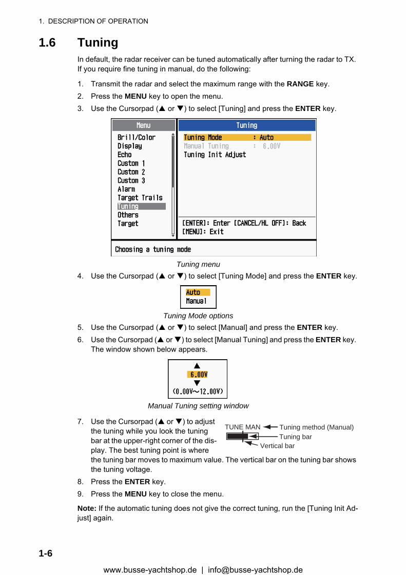
1.6 TuningIn default, the radar receiver can be tuned automatically after turning the radar to TX. If you require fine tuning in manual, do the following:
1. Transmit the radar and select the maximum range with the RANGE key.2. Press the MENU key to open the menu.3. Use the Cursorpad ( or ) to select [Tuning] and press the ENTER key.
Tuning menu4. Use the Cursorpad ( or ) to select [Tuning Mode] and press the ENTER key.
Tuning Mode options5. Use the Cursorpad ( or ) to select [Manual] and press the ENTER key.6. Use the Cursorpad ( or ) to select [Manual Tuning] and press the ENTER key.
The window shown below appears.
Manual Tuning setting window
7. Use the Cursorpad ( or ) to adjust the tuning while you look the tuning bar at the upper-right corner of the dis-play. The best tuning point is where the tuning bar moves to maximum value. The vertical bar on the tuning bar shows the tuning voltage.
8. Press the ENTER key.9. Press the MENU key to close the menu.
Note: If the automatic tuning does not give the correct tuning, run the [Tuning Init Ad-just] again.
TUNE MAN Tuning method (Manual)Tuning bar
Vertical bar
1-6www.busse-yachtshop.de | [email protected]

1. DESCRIPTION OF OPERATION
1.7 Display ModesThis radar has the display modes shown below. All modes except head-up require a heading signal. The true motion mode additionally requires position data.
Relative Motion (RM)
• [Head Up] (H UP)• [Course Up] (C UP)• [North Up] (N UP)• [True View] (TRUE VIEW)
True Motion (TM)
• [True Motion] (TM)
1.7.1 How to select the display mode1. Press the MENU key to open the menu.2. Use the Cursorpad ( or ) to select [Display] and press the ENTER key.
Display menu3. Use the Cursorpad ( or ) to select [Display Mode] and press the ENTER key.
Display Mode options4. Use the Cursorpad ( or ) to select a display mode and press the ENTER key.5. Press the MENU key to close the menu.
Note: All modes except head-up require a heading signal in AD-10 format or NMEA format. If the heading signal is lost, the mode is changed to head-up and the north marker disappears. The display for heading is XXX.X and the alarm sounds. The mes-sage "GYRO" (AD-10 format data) or "NMEA_HDG" (NMEA format data) appears in
1-7www.busse-yachtshop.de | [email protected]
1. DESCRIPTION OF OPERATION
the alarm message display. To stop the audio alarm, press any key. When the heading signal is restored, check the heading. To check the heading, press the F3 key. The numeric value is displayed at the heading indication when the heading signal is re-stored.
1.7.2 Description of display modes
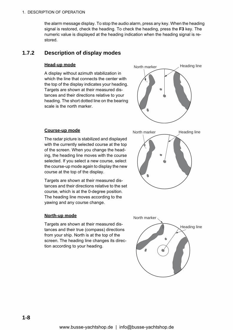
Head-up mode
A display without azimuth stabilization in which the line that connects the center with the top of the display indicates your heading. Targets are shown at their measured dis-tances and their directions relative to your heading. The short dotted line on the bearing scale is the north marker.
Course-up mode
The radar picture is stabilized and displayed with the currently selected course at the top of the screen. When you change the head-ing, the heading line moves with the course selected. If you select a new course, select the course-up mode again to display the new course at the top of the display.
Targets are shown at their measured dis-tances and their directions relative to the set course, which is at the 0-degree position. The heading line moves according to the yawing and any course change.
North-up mode
Targets are shown at their measured dis-tances and their true (compass) directions from your ship. North is at the top of the screen. The heading line changes its direc-tion according to your heading.
Heading lineNorth marker
Heading lineNorth marker
Heading line
North marker
1-8www.busse-yachtshop.de | [email protected]
1. DESCRIPTION OF OPERATION
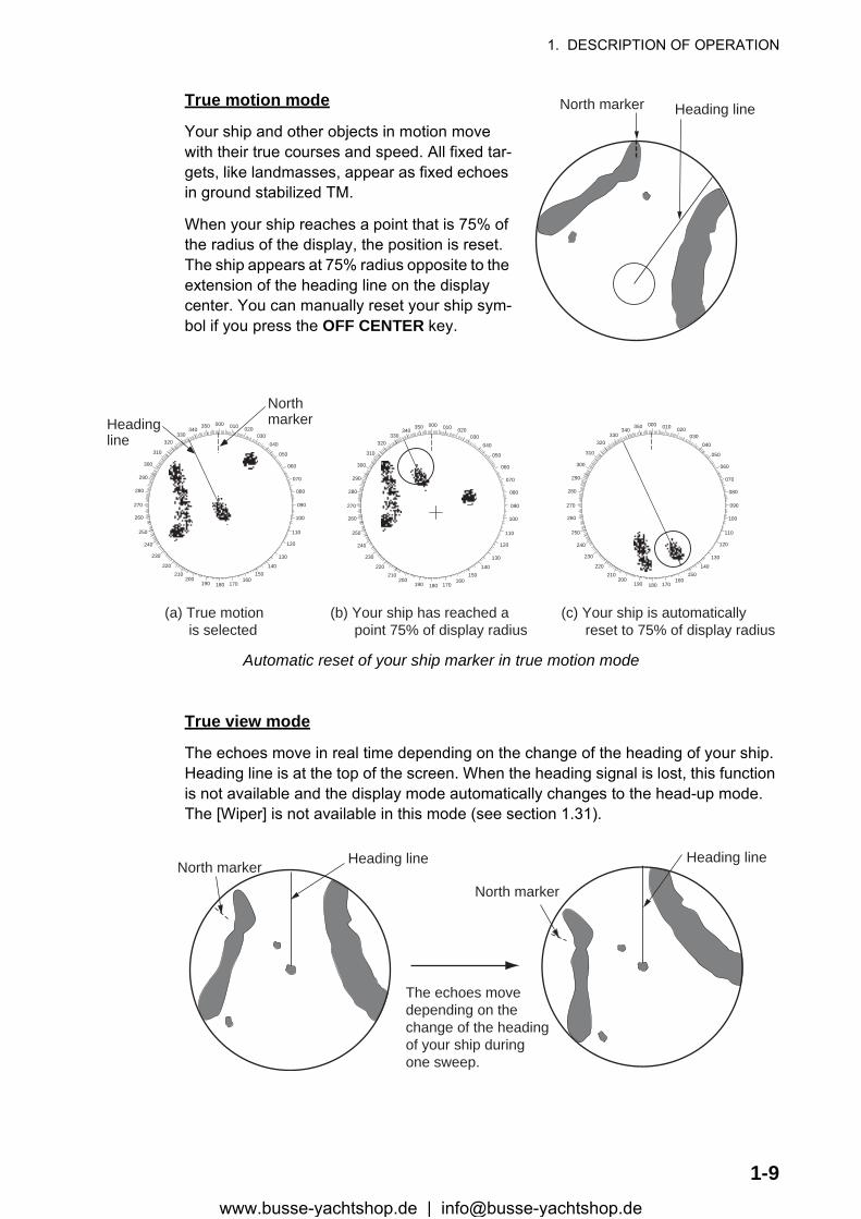
True motion mode
Your ship and other objects in motion move with their true courses and speed. All fixed tar-gets, like landmasses, appear as fixed echoes in ground stabilized TM.
When your ship reaches a point that is 75% of the radius of the display, the position is reset. The ship appears at 75% radius opposite to the extension of the heading line on the display center. You can manually reset your ship sym-bol if you press the OFF CENTER key.
Automatic reset of your ship marker in true motion mode
True view mode
The echoes move in real time depending on the change of the heading of your ship. Heading line is at the top of the screen. When the heading signal is lost, this function is not available and the display mode automatically changes to the head-up mode. The [Wiper] is not available in this mode (see section 1.31).
Heading lineNorth marker
000 010 020030
040
050
060
070
080
090
100
110
120
130
140150
160170180190
200210
220
230
240
250
260
270
280
290
300
310
320330
340350Heading
line
Northmarker
(a) True motion is selected
(b) Your ship has reached a point 75% of display radius
(c) Your ship is automatically reset to 75% of display radius
000 010 020030
040
050
060
070
080
090
100
110
120
130
140150
160170180190
200210
220
230
240
250
260
270
280
290
300
310
320330
340350 000 010 020
030040
050
060
070
080
090
100
110
120
130
140150
160170180190
200210
220
230
240
250
260
270
280
290
300
310
320330
340350
Heading lineNorth markerHeading line
North marker
The echoes movedepending on thechange of the headingof your ship duringone sweep.
1-9www.busse-yachtshop.de | [email protected]
1. DESCRIPTION OF OPERATION
1.8 How to Select a Range ScaleThe selected range scale, range ring interval and pulselength are shown at the upper- left corner on the screen. When an objective target comes closer, reduce the range scale so that a target appears in 50-90% of the display radius.
Use the RANGE key to select range. Press the "+" part of the key to raise the range; the "-" part to lower the range.
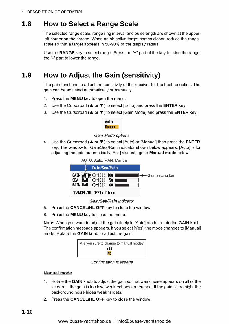
1.9 How to Adjust the Gain (sensitivity)The gain functions to adjust the sensitivity of the receiver for the best reception. The gain can be adjusted automatically or manually.
1. Press the MENU key to open the menu.2. Use the Cursorpad ( or ) to select [Echo] and press the ENTER key.3. Use the Cursorpad ( or ) to select [Gain Mode] and press the ENTER key.
Gain Mode options4. Use the Cursorpad ( or ) to select [Auto] or [Manual] then press the ENTER
key. The window for Gain/Sea/Rain indicator shown below appears. [Auto] is for adjusting the gain automatically. For [Manual], go to Manual mode below.
Gain/Sea/Rain indicator5. Press the CANCEL/HL OFF key to close the window.6. Press the MENU key to close the menu.
Note: When you want to adjust the gain finely in [Auto] mode, rotate the GAIN knob. The confirmation message appears. If you select [Yes], the mode changes to [Manual] mode. Rotate the GAIN knob to adjust the gain.
Confirmation message
Manual mode
1. Rotate the GAIN knob to adjust the gain so that weak noise appears on all of the screen. If the gain is too low, weak echoes are erased. If the gain is too high, the background noise hides weak targets.
2. Press the CANCEL/HL OFF key to close the window.
AUTO: Auto, MAN: Manual
Gain setting bar
Are you sure to change to manual mode?
1-10www.busse-yachtshop.de | [email protected]
1. DESCRIPTION OF OPERATION
1.10 How to Reduce the Sea ClutterThe reflected echoes from the waves appear around your ship and have the name "sea clutter". The sea clutter extends according to the height of waves and antenna above the water. When the sea clutter hides the targets, use the A/C SEA control to reduce the clutter, either manually or automatically.
1. Press the MENU key to open the menu.2. Use the Cursorpad ( or ) to select [Echo] and press the ENTER key.3. Use the Cursorpad ( or ) to select [Sea Mode] and press the ENTER key.4. Use the Cursorpad ( or ) to select [Auto] or [Manual] then press the ENTER
key. The window for Gain/Sea/Rain indicator appears (refer to the illustration at step 4 in section 1.9). [Auto] is for reducing the sea clutter automatically. For [Man-ual], go to Manual mode below.
5. Press the CANCEL/HL OFF key to close the window.6. Press the MENU key to close the menu.
Note: When you want to adjust the sea clutter finely in [Auto] mode, rotate the A/C SEA knob. The confirmation message appears. If you select [Yes], the mode changes to [Manual] mode. Rotate the A/C SEA knob to adjust the sea clutter.
Confirmation message
Manual mode
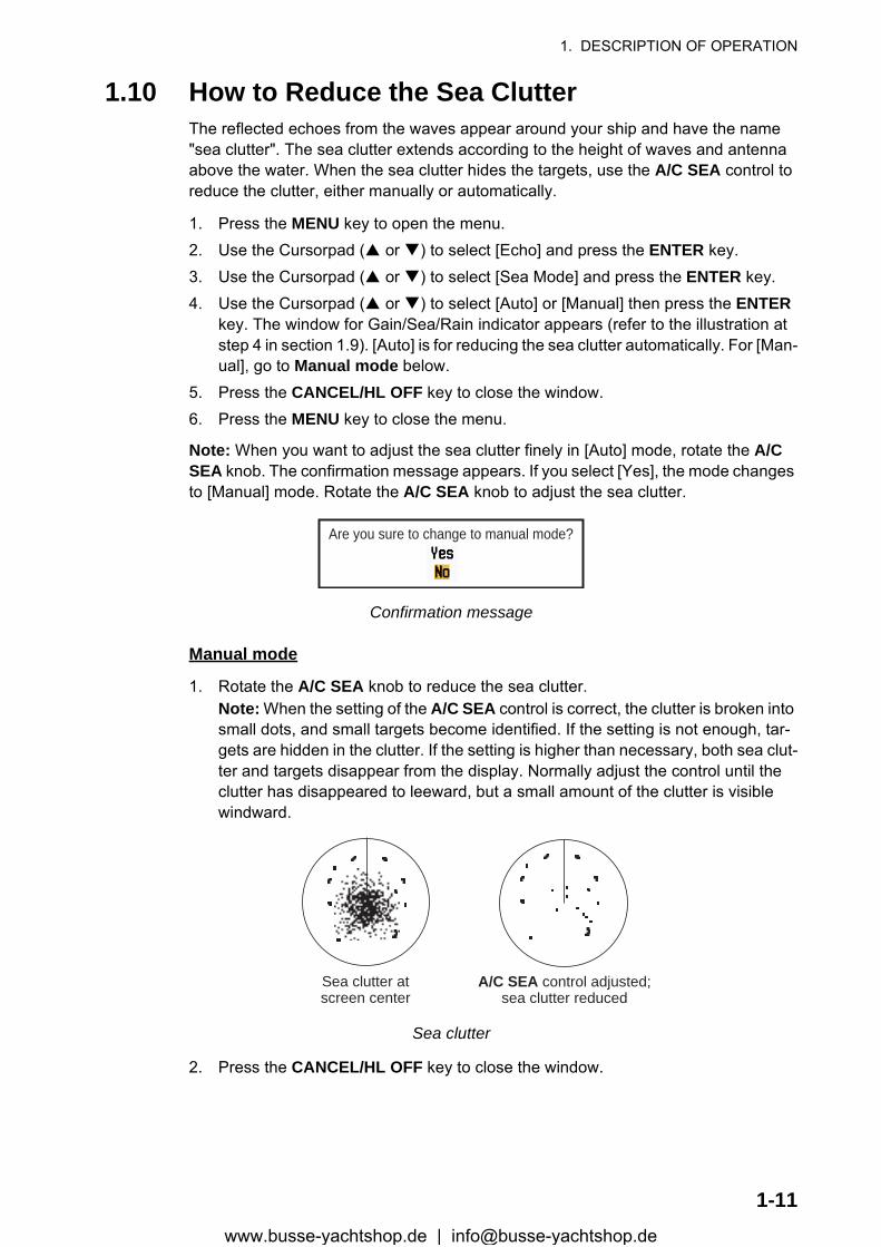
1. Rotate the A/C SEA knob to reduce the sea clutter.Note: When the setting of the A/C SEA control is correct, the clutter is broken into small dots, and small targets become identified. If the setting is not enough, tar-gets are hidden in the clutter. If the setting is higher than necessary, both sea clut-ter and targets disappear from the display. Normally adjust the control until the clutter has disappeared to leeward, but a small amount of the clutter is visible windward.
Sea clutter
2. Press the CANCEL/HL OFF key to close the window.
Are you sure to change to manual mode?
A/C SEA control adjusted;sea clutter reduced
Sea clutter atscreen center
1-11www.busse-yachtshop.de | [email protected]
1. DESCRIPTION OF OPERATION
1.11 How to Reduce the Rain ClutterThe reflections from the rain or snow appear on the screen. These reflections have the name "rain clutter". When the rain clutter is strong, targets in the rain clutter are hidden in the clutter. Reflections from the rain clutter are easily identified from true targets by their wool-like appearance.
The A/C RAIN control, like the A/C SEA control, adjusts the receiver sensitivity, but in longer range. If the setting is high, the rain clutter is more reduced. The rain control breaks the continuous display of rain or snow reflections into a random pattern. When the rain clutter hides the targets, adjust the rain control (automatic or manual) to re-duce the clutter.
1. Press the MENU key to open the menu.2. Use the Cursorpad ( or ) to select [Echo] and press the ENTER key.3. Use the Cursorpad ( or ) to select [Rain Mode] and press the ENTER key.4. Use the Cursorpad ( or ) to select [Auto] or [Manual] then press the ENTER
key. The window for Gain/Sea/Rain indicator appears (refer to the illustration of step 4 at section 1.9). If you selected [Auto], go to step 5. For [Manual], go to Man-ual mode below.
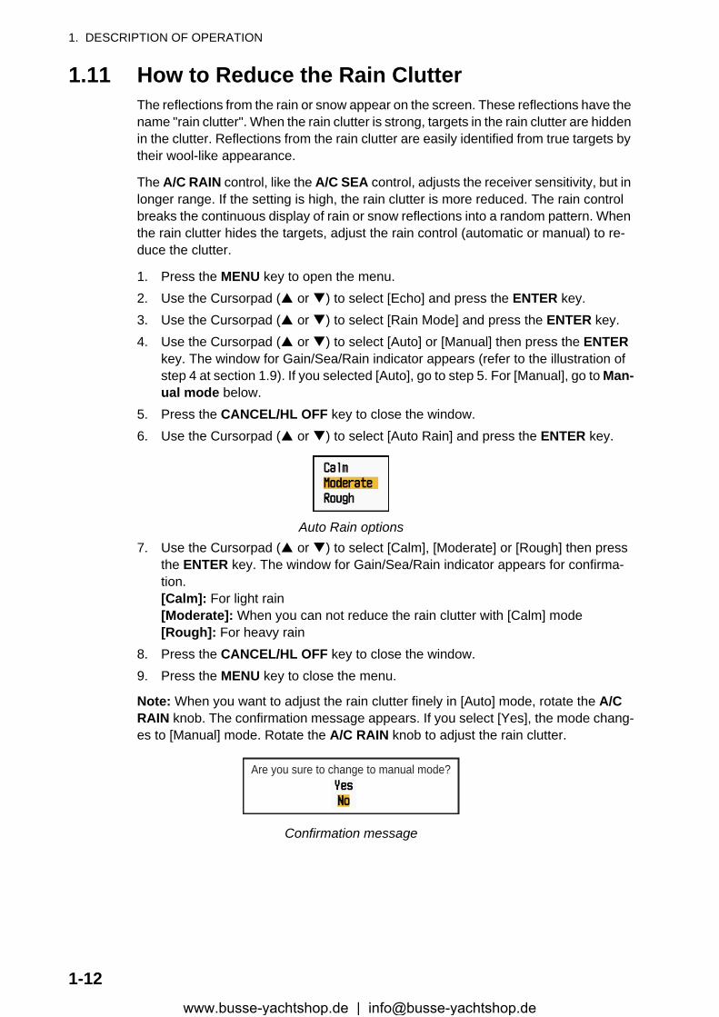
5. Press the CANCEL/HL OFF key to close the window.6. Use the Cursorpad ( or ) to select [Auto Rain] and press the ENTER key.
Auto Rain options7. Use the Cursorpad ( or ) to select [Calm], [Moderate] or [Rough] then press
the ENTER key. The window for Gain/Sea/Rain indicator appears for confirma-tion.[Calm]: For light rain[Moderate]: When you can not reduce the rain clutter with [Calm] mode[Rough]: For heavy rain
8. Press the CANCEL/HL OFF key to close the window.9. Press the MENU key to close the menu.
Note: When you want to adjust the rain clutter finely in [Auto] mode, rotate the A/C RAIN knob. The confirmation message appears. If you select [Yes], the mode chang-es to [Manual] mode. Rotate the A/C RAIN knob to adjust the rain clutter.
Confirmation message
Are you sure to change to manual mode?
1-12www.busse-yachtshop.de | [email protected]

1. DESCRIPTION OF OPERATION
Manual mode
1. Rotate the A/C RAIN knob to reduce the rain clutter.2. Press the CANCEL/HL OFF key to close the window.
Rain clutter
1.12 Automatic Adjustments of Sea and Rain Clutters When you can not correctly reduce the sea clutter or rain clutter with related control, turn on the automatic anti-clutter feature. When this feature is turned on, "A/C AUTO" appears at the lower-right corner.
1. Press the MENU key to open the menu.2. Use the Cursorpad ( or ) to select [Echo] and press the ENTER key.3. Use the Cursorpad ( or ) to select [A/C Auto] and press the ENTER key.4. Use the Cursorpad ( or ) to select [Off] or [On] then press the ENTER key.5. Press the MENU key to close the menu.
Caution on use
• [A/C Auto] can lower an echo which covers a wide area, like land or an island.• When [A/C Auto] is active, the strength of a target in sea clutter or rain clutter can
be lower than actual strength. In this case change to manual A/C Sea and manual A/C Rain and adjust the picture.
Rain clutter atscreen center
A/C RAIN control adjusted;rain clutter reduced
A/C Auto: Off A/C Auto: On
:£::̧Å:»Land
:£::̧Å:»Target
1-13www.busse-yachtshop.de | [email protected]

1. DESCRIPTION OF OPERATION
1.13 CursorThe cursor functions to find the range and bearing (default function) to a target or the latitude and longitude position of a target. Use the Cursorpad to position the cursor and read the cursor data at the screen bottom.
Cursor data
Cursor data
You can show the cursor data as range and bearing (from your ship to the cursor) or latitude and longitude. Position and heading signal are required.
1. Press the MENU key to open the menu.2. Use the Cursorpad ( or ) to select [Others] and press the ENTER key.
Others menu
Cursor data(range and bearing, or latitutde and longitude)
110.1° R 0.488 NM
NM0.5
Cursor+
+
1-14www.busse-yachtshop.de | [email protected]
1. DESCRIPTION OF OPERATION
3. Use the Cursorpad ( or ) to select [Cursor Position] and press the ENTER key.
Cursor Position options4. Use the Cursorpad ( or ) to select [Rng/Brg] or [Lat/Lon] then press the EN-
TER key. (When the navigation data is displayed, cursor latitude and longitude po-sition cannot be displayed.)
5. Press the MENU key to close the menu.
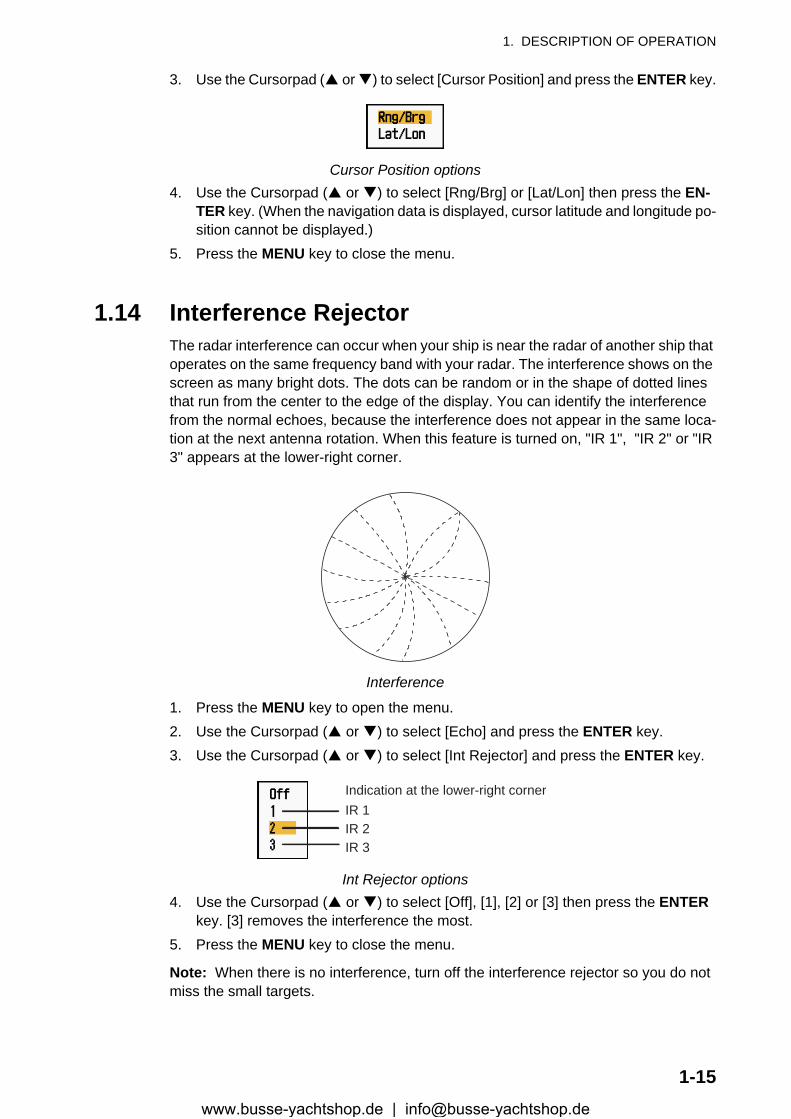
1.14 Interference RejectorThe radar interference can occur when your ship is near the radar of another ship that operates on the same frequency band with your radar. The interference shows on the screen as many bright dots. The dots can be random or in the shape of dotted lines that run from the center to the edge of the display. You can identify the interference from the normal echoes, because the interference does not appear in the same loca-tion at the next antenna rotation. When this feature is turned on, "IR 1", "IR 2" or "IR 3" appears at the lower-right corner.
Interference
1. Press the MENU key to open the menu.2. Use the Cursorpad ( or ) to select [Echo] and press the ENTER key.3. Use the Cursorpad ( or ) to select [Int Rejector] and press the ENTER key.
Int Rejector options4. Use the Cursorpad ( or ) to select [Off], [1], [2] or [3] then press the ENTER
key. [3] removes the interference the most.5. Press the MENU key to close the menu.
Note: When there is no interference, turn off the interference rejector so you do not miss the small targets.
Indication at the lower-right cornerIR 1IR 2IR 3
1-15www.busse-yachtshop.de | [email protected]
1. DESCRIPTION OF OPERATION
1.15 How to Measure the Range to a TargetYou can measure the range to a target in three methods. You can use the fixed range rings, the cursor (if set to measure range and bearing), and the VRM (Variable Range Marker).
Use the fixed range rings to get a rough estimate of the range to a target. The fixed range rings are the concentric solid circles about your ship. The number of rings changes with the selected range scale. The interval of the range ring is displayed at the upper-left corner of the screen. Count the number of rings between the center of the display and the target. Check the range ring interval and measure the distance of the echo from the nearest ring.
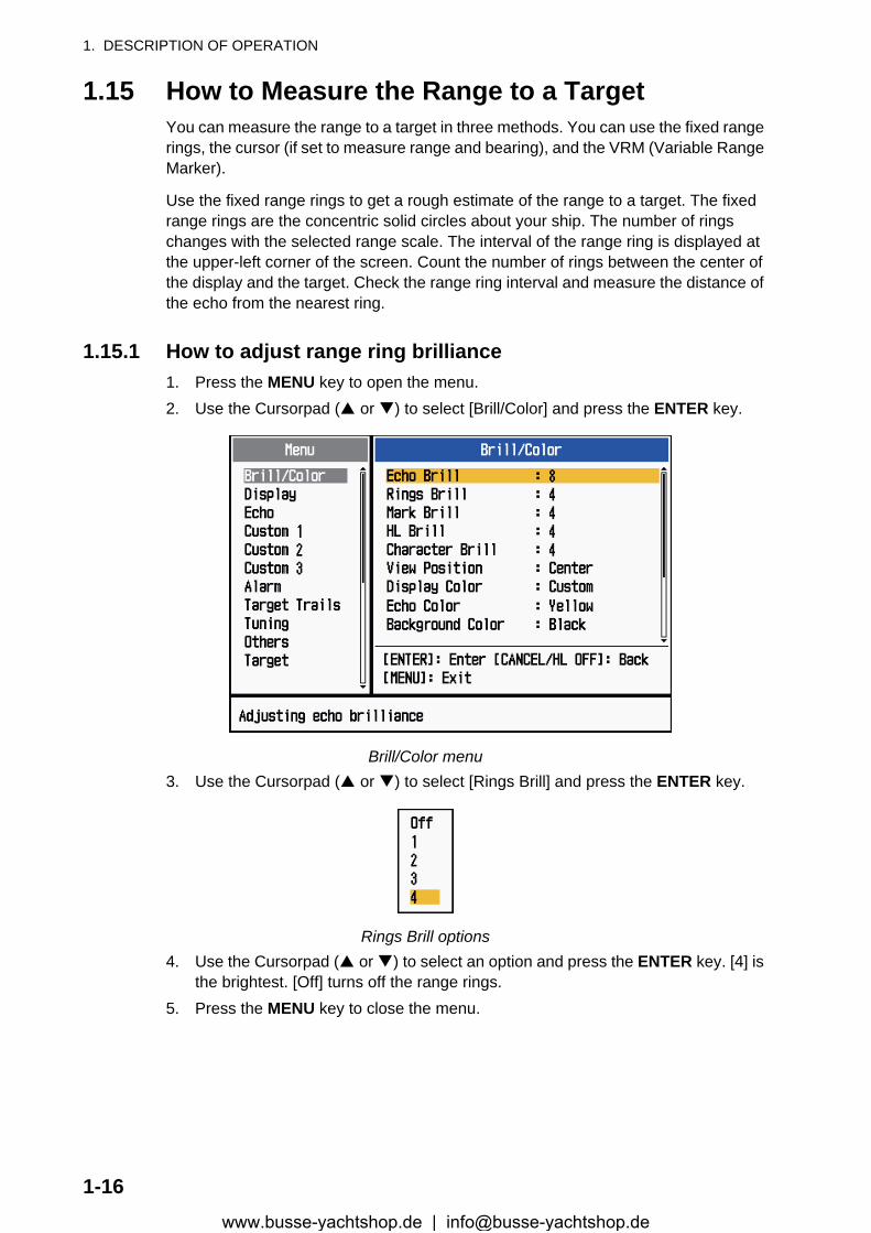
1.15.1 How to adjust range ring brilliance1. Press the MENU key to open the menu.2. Use the Cursorpad ( or ) to select [Brill/Color] and press the ENTER key.
Brill/Color menu3. Use the Cursorpad ( or ) to select [Rings Brill] and press the ENTER key.
Rings Brill options4. Use the Cursorpad ( or ) to select an option and press the ENTER key. [4] is
the brightest. [Off] turns off the range rings.5. Press the MENU key to close the menu.
1-16www.busse-yachtshop.de | [email protected]
1. DESCRIPTION OF OPERATION
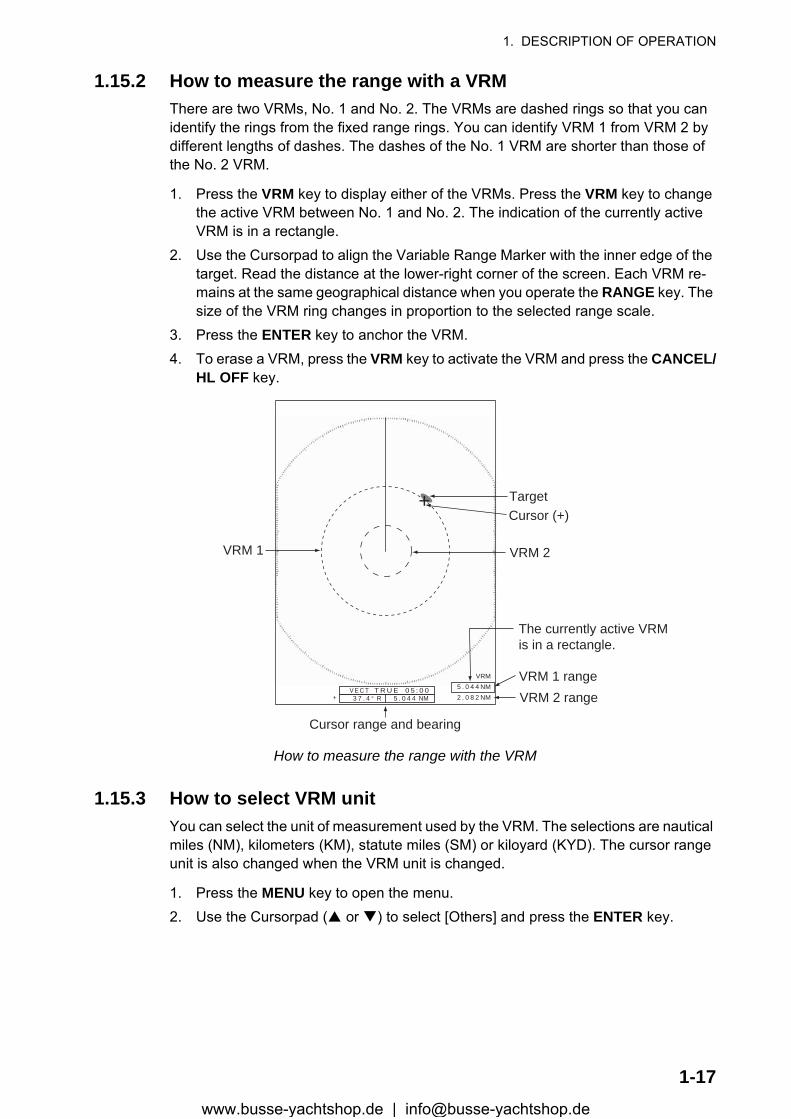
1.15.2 How to measure the range with a VRMThere are two VRMs, No. 1 and No. 2. The VRMs are dashed rings so that you can identify the rings from the fixed range rings. You can identify VRM 1 from VRM 2 by different lengths of dashes. The dashes of the No. 1 VRM are shorter than those of the No. 2 VRM.
1. Press the VRM key to display either of the VRMs. Press the VRM key to change the active VRM between No. 1 and No. 2. The indication of the currently active VRM is in a rectangle.
2. Use the Cursorpad to align the Variable Range Marker with the inner edge of the target. Read the distance at the lower-right corner of the screen. Each VRM re-mains at the same geographical distance when you operate the RANGE key. The size of the VRM ring changes in proportion to the selected range scale.
3. Press the ENTER key to anchor the VRM.4. To erase a VRM, press the VRM key to activate the VRM and press the CANCEL/
HL OFF key.
How to measure the range with the VRM
1.15.3 How to select VRM unitYou can select the unit of measurement used by the VRM. The selections are nautical miles (NM), kilometers (KM), statute miles (SM) or kiloyard (KYD). The cursor range unit is also changed when the VRM unit is changed.
1. Press the MENU key to open the menu.2. Use the Cursorpad ( or ) to select [Others] and press the ENTER key.
VRM 1
Cursor range and bearing
VRM 2
Target+
VRM5 . 0 4 4 NM2 . 0 8 2 NM
Cursor (+)
VRM 1 rangeVRM 2 range+
The currently active VRMis in a rectangle.
3 7 . 4 ° R 5 . 0 4 4 NM V E C T T R U E 0 5 : 0 0
1-17www.busse-yachtshop.de | [email protected]
1. DESCRIPTION OF OPERATION
3. Use the Cursorpad ( or ) to select [VRM Unit] and press the ENTER key.
VRM Unit options4. Use the Cursorpad ( or ) to select the unit and press the ENTER key.5. Press the MENU key to close the menu.
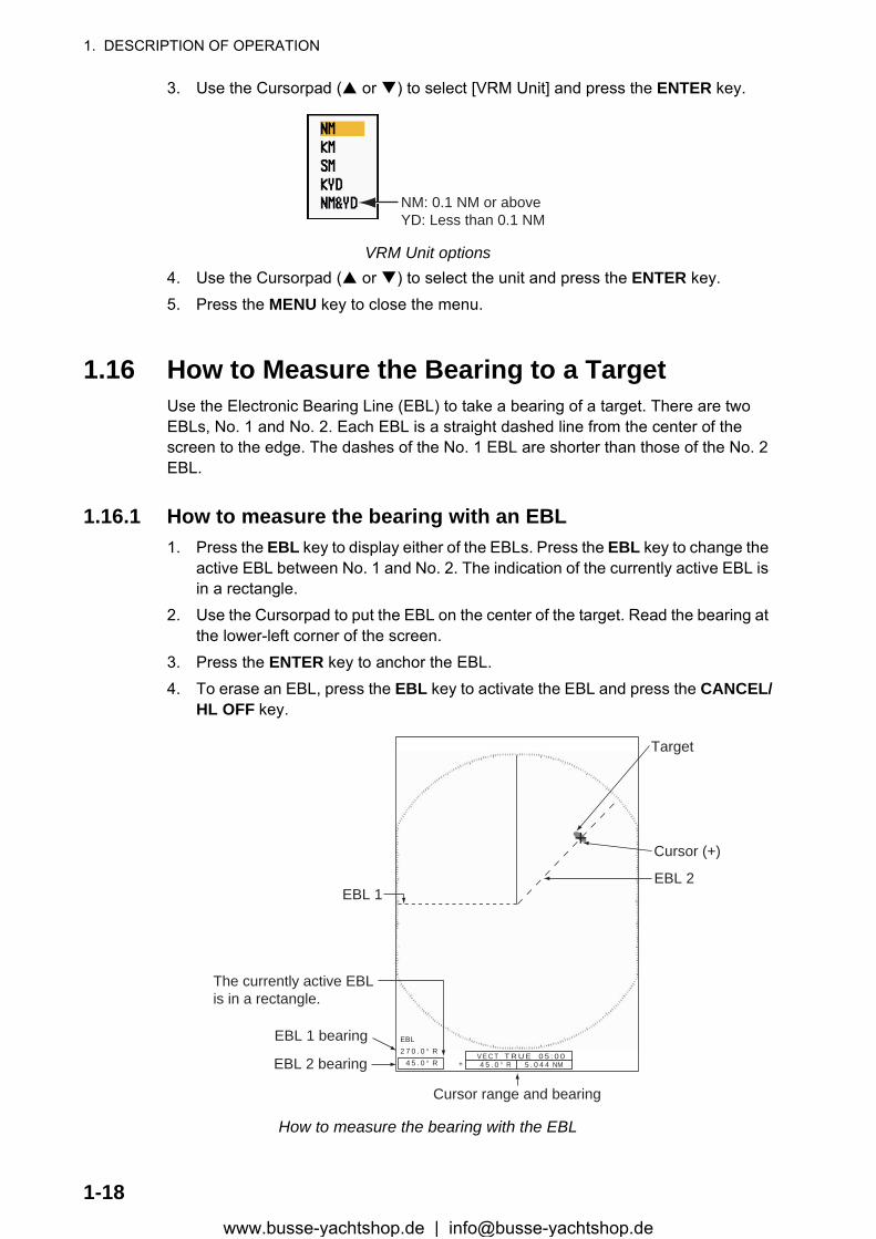
1.16 How to Measure the Bearing to a TargetUse the Electronic Bearing Line (EBL) to take a bearing of a target. There are two EBLs, No. 1 and No. 2. Each EBL is a straight dashed line from the center of the screen to the edge. The dashes of the No. 1 EBL are shorter than those of the No. 2 EBL.
1.16.1 How to measure the bearing with an EBL1. Press the EBL key to display either of the EBLs. Press the EBL key to change the
active EBL between No. 1 and No. 2. The indication of the currently active EBL is in a rectangle.
2. Use the Cursorpad to put the EBL on the center of the target. Read the bearing at the lower-left corner of the screen.
3. Press the ENTER key to anchor the EBL.4. To erase an EBL, press the EBL key to activate the EBL and press the CANCEL/
HL OFF key.
How to measure the bearing with the EBL
NM: 0.1 NM or aboveYD: Less than 0.1 NM
+
EBL2 7 0 . 0 ° R 4 5 . 0 ° R 4 5 . 0 ° R 5 . 0 4 4 NM +
EBL 1EBL 2
Cursor range and bearing
Target
Cursor (+)
The currently active EBLis in a rectangle.
EBL 1 bearing
EBL 2 bearingV E C T T R U E 0 5 : 0 0
1-18www.busse-yachtshop.de | [email protected]
1. DESCRIPTION OF OPERATION
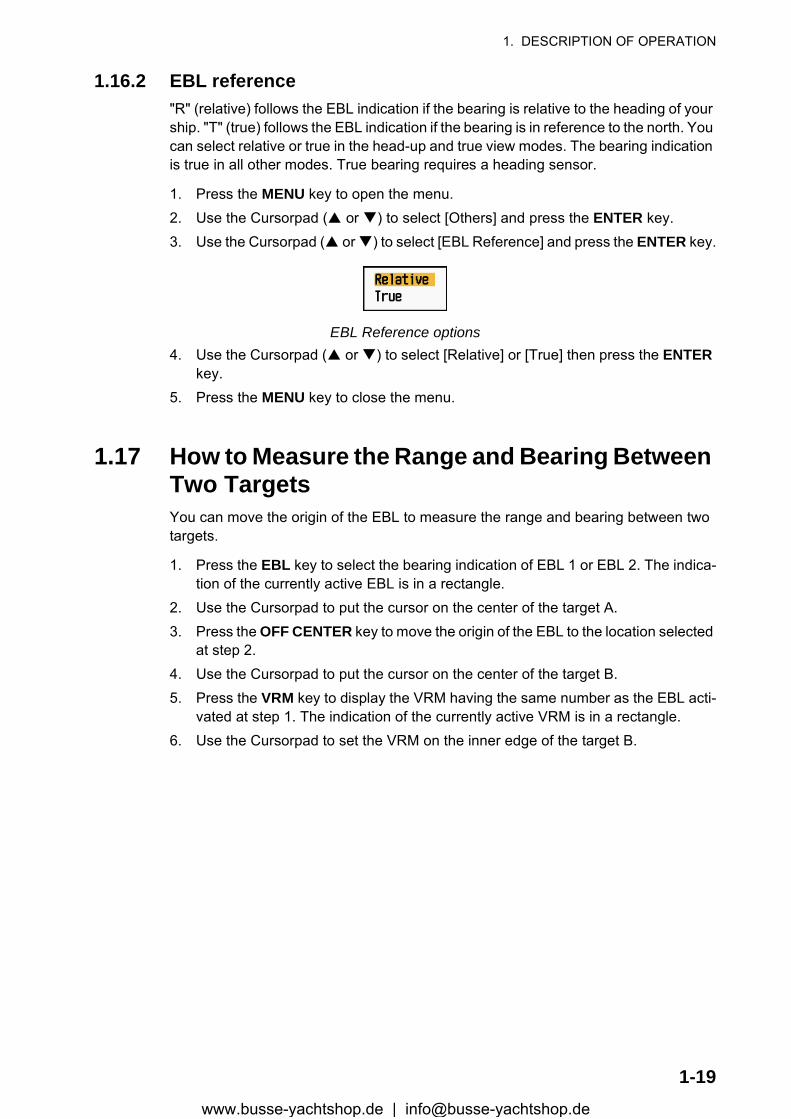
1.16.2 EBL reference"R" (relative) follows the EBL indication if the bearing is relative to the heading of your ship. "T" (true) follows the EBL indication if the bearing is in reference to the north. You can select relative or true in the head-up and true view modes. The bearing indication is true in all other modes. True bearing requires a heading sensor.
1. Press the MENU key to open the menu.2. Use the Cursorpad ( or ) to select [Others] and press the ENTER key.3. Use the Cursorpad ( or ) to select [EBL Reference] and press the ENTER key.
EBL Reference options4. Use the Cursorpad ( or ) to select [Relative] or [True] then press the ENTER
key.5. Press the MENU key to close the menu.
1.17 How to Measure the Range and Bearing Between Two TargetsYou can move the origin of the EBL to measure the range and bearing between two targets.
1. Press the EBL key to select the bearing indication of EBL 1 or EBL 2. The indica-tion of the currently active EBL is in a rectangle.
2. Use the Cursorpad to put the cursor on the center of the target A.3. Press the OFF CENTER key to move the origin of the EBL to the location selected
at step 2.4. Use the Cursorpad to put the cursor on the center of the target B.5. Press the VRM key to display the VRM having the same number as the EBL acti-
vated at step 1. The indication of the currently active VRM is in a rectangle.6. Use the Cursorpad to set the VRM on the inner edge of the target B.
1-19www.busse-yachtshop.de | [email protected]

1. DESCRIPTION OF OPERATION
7. Read the bearing and range indications at the bottom of the screen.
How to measure the range and bearing between two targetsWhen you press the OFF CENTER key in EBL operation, the origin of an EBL moves between the screen center and cursor location. To return the origin of an EBL to the screen center, press the ENTER key when the origin of an EBL is on the screen cen-ter.
1.18 How to Select a PulselengthThe pulselength in use appears at the upper-left position on the screen. The pulse-lengths are set to each range scale and custom setup. You can change the pulse-length on the 1.5 nm, 1.6 nm, 3 nm or 3.2 nm range with the following procedure. Pulselength cannot be changed on other ranges. (You can change the pulselength on the 2 nm or 4 nm range in the [Russian-River] mode.) Use a longer pulse when your purpose is long range detection. Use a shorter pulse when the resolution is important.
Note: Press the CUSTOM key several times to activate the [Echo] menu until the CS 1 (2, 3) indication (custom setting) disappears from the screen. See the illustration in section 1.3.
1. Press the MENU key to open the menu.
EBL origin
++
Target B
Range/bearing betweentargets A and B
Range/bearing betweentargets C and D
EBL 2
VRM 2
EBL 1
VRM 1
EBL 4 5 . 0 ° R3 2 7 . 0 ° R
VRM0 . 5 5 0 NM0 . 5 5 0 NM
Target A Target D
Target C
1-20www.busse-yachtshop.de | [email protected]
1. DESCRIPTION OF OPERATION
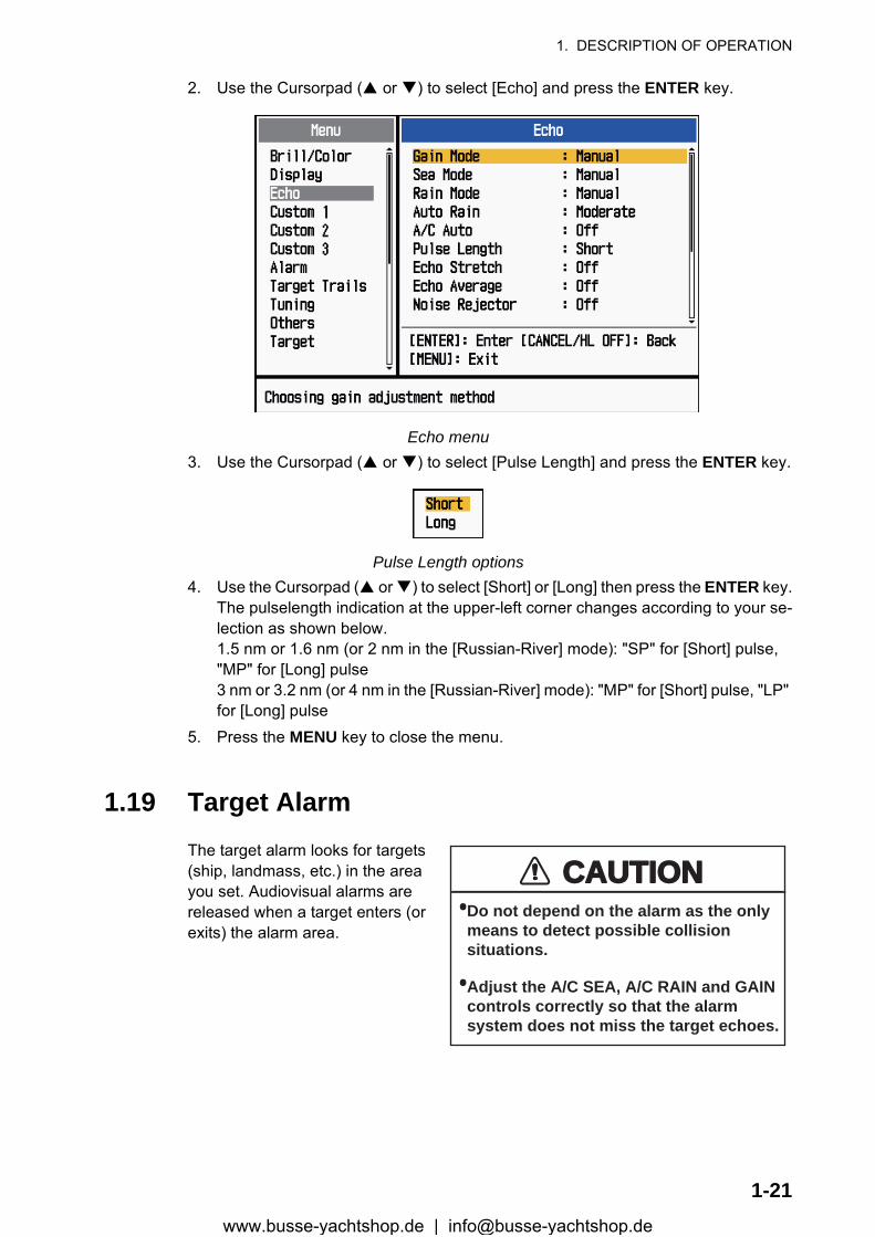
2. Use the Cursorpad ( or ) to select [Echo] and press the ENTER key.
Echo menu3. Use the Cursorpad ( or ) to select [Pulse Length] and press the ENTER key.
Pulse Length options4. Use the Cursorpad ( or ) to select [Short] or [Long] then press the ENTER key.
The pulselength indication at the upper-left corner changes according to your se-lection as shown below.1.5 nm or 1.6 nm (or 2 nm in the [Russian-River] mode): "SP" for [Short] pulse, "MP" for [Long] pulse3 nm or 3.2 nm (or 4 nm in the [Russian-River] mode): "MP" for [Short] pulse, "LP" for [Long] pulse
5. Press the MENU key to close the menu.
1.19 Target AlarmThe target alarm looks for targets (ship, landmass, etc.) in the area you set. Audiovisual alarms are released when a target enters (or exits) the alarm area.
CAUTIONCAUTION· Do not depend on the alarm as the only means to detect possible collision situations.
· Adjust the A/C SEA, A/C RAIN and GAIN controls correctly so that the alarm system does not miss the target echoes.
1-21www.busse-yachtshop.de | [email protected]
1. DESCRIPTION OF OPERATION
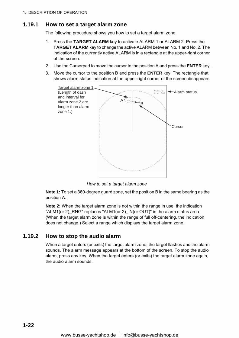
1.19.1 How to set a target alarm zoneThe following procedure shows you how to set a target alarm zone.
1. Press the TARGET ALARM key to activate ALARM 1 or ALARM 2. Press the TARGET ALARM key to change the active ALARM between No. 1 and No. 2. The indication of the currently active ALARM is in a rectangle at the upper-right corner of the screen.
2. Use the Cursorpad to move the cursor to the position A and press the ENTER key.3. Move the cursor to the position B and press the ENTER key. The rectangle that
shows alarm status indication at the upper-right corner of the screen disappears.
How to set a target alarm zone
Note 1: To set a 360-degree guard zone, set the position B in the same bearing as the position A.
Note 2: When the target alarm zone is not within the range in use, the indication "ALM1(or 2)_RNG" replaces "ALM1(or 2)_IN(or OUT)" in the alarm status area. (When the target alarm zone is within the range of full off-centering, the indication does not change.) Select a range which displays the target alarm zone.
1.19.2 How to stop the audio alarmWhen a target enters (or exits) the target alarm zone, the target flashes and the alarm sounds. The alarm message appears at the bottom of the screen. To stop the audio alarm, press any key. When the target enters (or exits) the target alarm zone again, the audio alarm sounds.
Cursor
+
Target alarm zone 1(Length of dashand interval foralarm zone 2 arelonger than alarmzone 1.)
AB
Alarm statusA L M 1 _ I NA L M 2 _ O U T
1-22www.busse-yachtshop.de | [email protected]

1. DESCRIPTION OF OPERATION
1.19.3 How to select the alarm typeYou can set the target alarm to activate against targets entering or exiting the alarm zone.
In and Out target alarms
1. Press the MENU key to open the menu.2. Use the Cursorpad ( or ) to select [Alarm] and press the ENTER key.
Alarm menu3. Use the Cursorpad ( or ) to select [Target Alarm 1] or [Target Alarm 2] then
press the ENTER key.
Target Alarm options4. Use the Cursorpad ( or ) to select [In] or [Out].
[In]: When the targets enter a target alarm zone, the alarm sounds.[Out]: When the targets exit a target alarm zone, the alarm sounds.
5. Press the ENTER key followed by the MENU key.
1.19.4 How to sleep a target alarm temporarilyWhen you do not require a target alarm temporarily, you can sleep the target alarm. The alarm zone remains on the screen, but any targets that enter (or exit) the alarm zone do not trigger the audio and visual alarms.
1. Press the TARGET ALARM key to select the ALARM 1 or ALARM 2 indication at the upper-right corner on the screen. The selected indication is in a rectangle.
“In” target alarm “Out” target alarm
1-23www.busse-yachtshop.de | [email protected]
1. DESCRIPTION OF OPERATION
2. Press the CANCEL/HL OFF key. The alarm indication now shows "ALM1(or 2)_ACK".
To activate a sleeping target alarm zone, press the TARGET ALARM key to select the ALARM 1 or ALARM 2 and press the ENTER key. The alarm indication then changes to "ALM1(or 2)_IN(or OUT)".
1.19.5 How to deactivate a target alarm1. Press the TARGET ALARM key to select the ALARM 1 or ALARM 2 indication at
the upper-right corner on the screen. The selected indication is in a rectangle.2. Press the CANCEL/HL OFF key. The alarm indication now shows "ALM1(or
2)_ACK".3. Press the TARGET ALARM key. The alarm indication "ALM1(or 2)_ACK" is
shown in a dashed-line rectangle.4. Press the CANCEL/HL OFF key. The target alarm zone and the alarm indication
are erased from the screen.
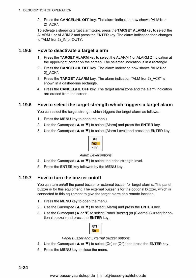
1.19.6 How to select the target strength which triggers a target alarmYou can select the target strength which triggers the target alarm as follows:
1. Press the MENU key to open the menu.2. Use the Cursorpad ( or ) to select [Alarm] and press the ENTER key.3. Use the Cursorpad ( or ) to select [Alarm Level] and press the ENTER key.
Alarm Level options4. Use the Cursorpad ( or ) to select the echo strength level.5. Press the ENTER key followed by the MENU key.
1.19.7 How to turn the buzzer on/offYou can turn on/off the panel buzzer or external buzzer for target alarms. The panel buzzer is for this equipment. The external buzzer is for the optional buzzer, which is connected to this equipment to give the target alarm at a remote location.
1. Press the MENU key to open the menu.2. Use the Cursorpad ( or ) to select [Alarm] and press the ENTER key.3. Use the Cursorpad ( or ) to select [Panel Buzzer] (or [External Buzzer] for op-
tional buzzer) and press the ENTER key.
Panel Buzzer and External Buzzer options4. Use the Cursorpad ( or ) to select [On] or [Off] then press the ENTER key.5. Press the MENU key to close the menu.
1-24www.busse-yachtshop.de | [email protected]
1. DESCRIPTION OF OPERATION
1.20 How to Off-center the DisplayYou can off-center your ship position to expand the view field without selecting a larger range scale. The display can be off-centered manually, or automatically according to speed of the ship.
Note: Off-centering is not available in the true motion mode.
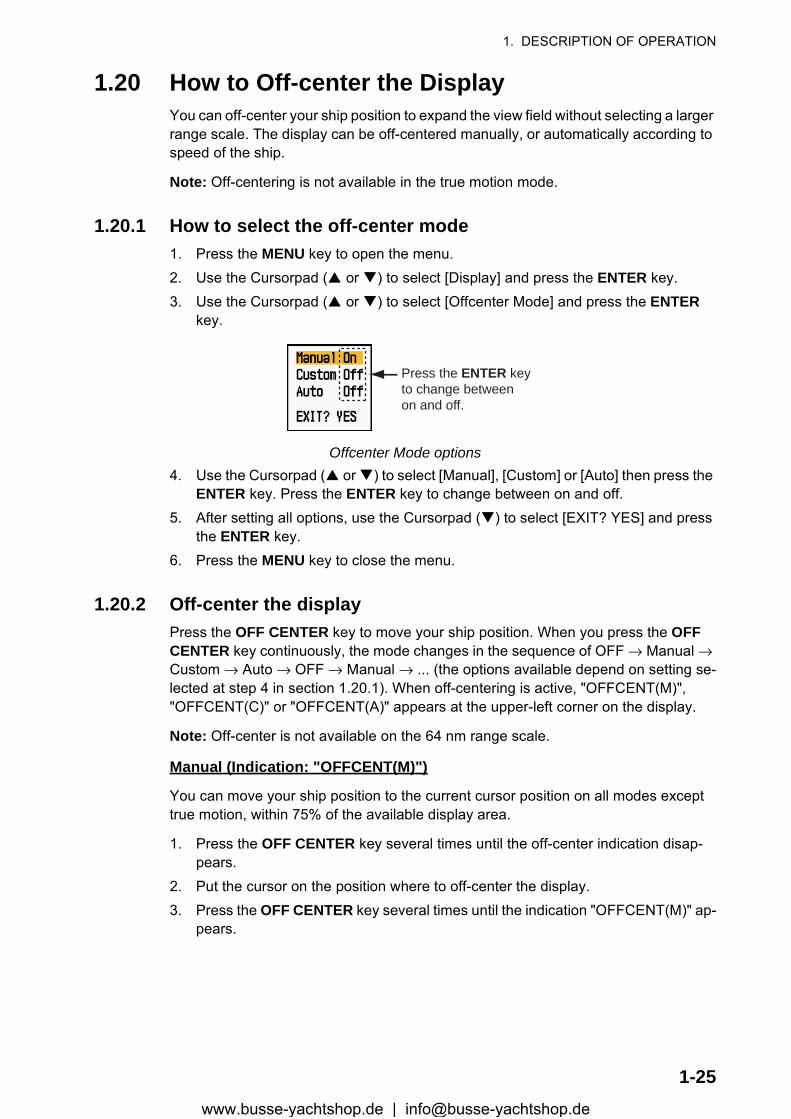
1.20.1 How to select the off-center mode1. Press the MENU key to open the menu.2. Use the Cursorpad ( or ) to select [Display] and press the ENTER key.3. Use the Cursorpad ( or ) to select [Offcenter Mode] and press the ENTER
key.
Offcenter Mode options4. Use the Cursorpad ( or ) to select [Manual], [Custom] or [Auto] then press the
ENTER key. Press the ENTER key to change between on and off.5. After setting all options, use the Cursorpad ( ) to select [EXIT? YES] and press
the ENTER key.6. Press the MENU key to close the menu.
1.20.2 Off-center the displayPress the OFF CENTER key to move your ship position. When you press the OFF CENTER key continuously, the mode changes in the sequence of OFF → Manual → Custom → Auto → OFF → Manual → ... (the options available depend on setting se-lected at step 4 in section 1.20.1). When off-centering is active, "OFFCENT(M)", "OFFCENT(C)" or "OFFCENT(A)" appears at the upper-left corner on the display.
Note: Off-center is not available on the 64 nm range scale.
Manual (Indication: "OFFCENT(M)")
You can move your ship position to the current cursor position on all modes except true motion, within 75% of the available display area.
1. Press the OFF CENTER key several times until the off-center indication disap-pears.
2. Put the cursor on the position where to off-center the display.3. Press the OFF CENTER key several times until the indication "OFFCENT(M)" ap-
pears.
Press the ENTER keyto change betweenon and off.
1-25www.busse-yachtshop.de | [email protected]
1. DESCRIPTION OF OPERATION
Custom (Indication: "OFFCENT(C)")
You can move your ship position to the position which you pre-set. Follow the proce-dure shown below to register the cursor position.
1. Press the OFF CENTER key several times until the off-center indication disap-pears.
2. Put the cursor on the position where to off-center the display.3. Press the OFF CENTER key several times until the indication "OFFCENT(M)" ap-
pears.4. Press the MENU key to open the menu.5. Use the Cursorpad ( or ) to select [Display] and press the ENTER key.6. Use the Cursorpad ( or ) to select [Save Offcenter] and press the ENTER key.
The message "Complete" appears.7. Press any key to close the message window.8. Press the MENU key to close the menu.To change the mode to custom, press the OFF CENTER key several times until the indication "OFFCENT(C)" appears.
Auto (Indication: "OFFCENT(A)")
The amount of automatic move is calculated according to speed of the ship. The max-imum amount is 75% of the range in use. The formula to calculate automatic shift is shown below.
If the offcenter speed setting is 15 knots and the speed of the ship is 10 knots, for ex-ample, the amount of move at the stern of your ship will be 50% of the available display area.
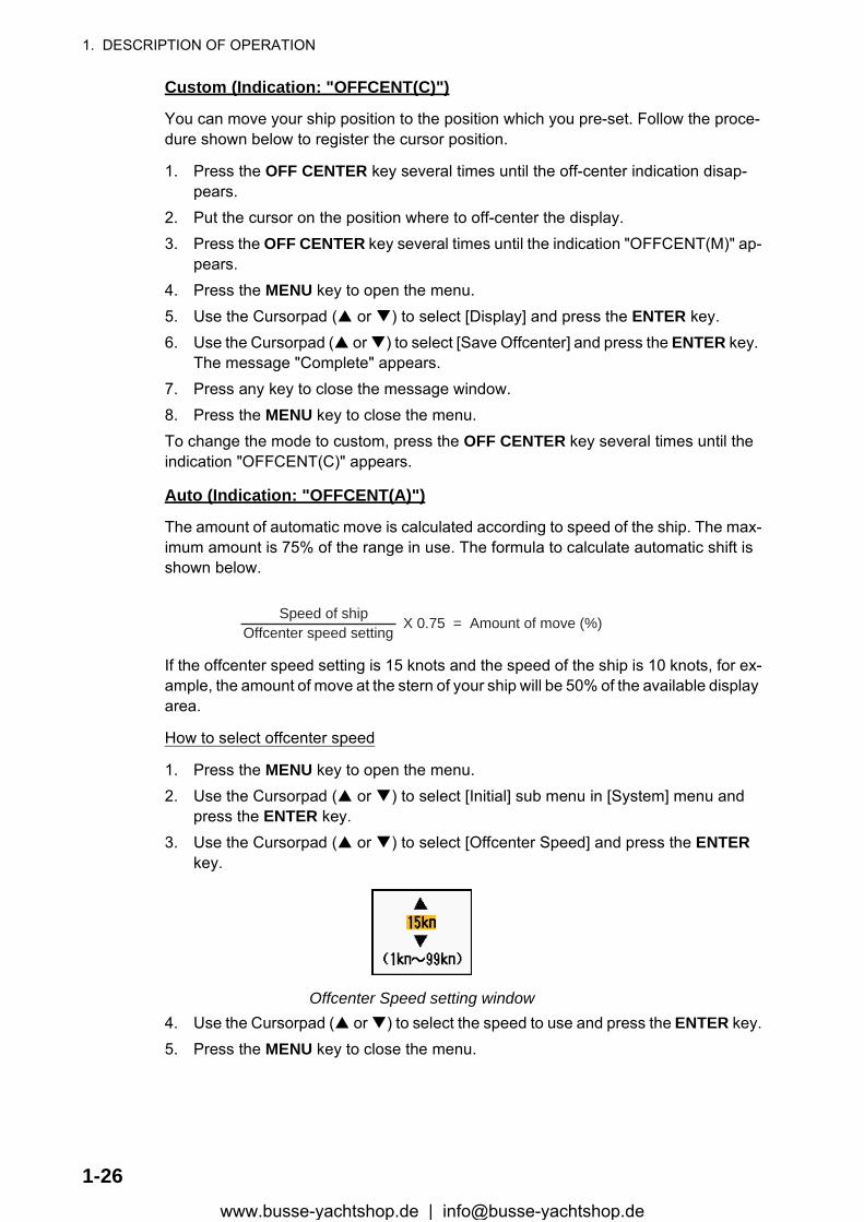
How to select offcenter speed
1. Press the MENU key to open the menu.2. Use the Cursorpad ( or ) to select [Initial] sub menu in [System] menu and
press the ENTER key.3. Use the Cursorpad ( or ) to select [Offcenter Speed] and press the ENTER
key.
Offcenter Speed setting window4. Use the Cursorpad ( or ) to select the speed to use and press the ENTER key.5. Press the MENU key to close the menu.
Offcenter speed setting X 0.75 = Amount of move (%)
Speed of ship
1-26www.busse-yachtshop.de | [email protected]

1. DESCRIPTION OF OPERATION
1.21 ZoomThe zoom function expands the length and width of a selected target as much as twice its normal size, in the zoom window. You select the target to zoom with the zoom cur-sor. The selected target is zoomed in the zoom window.
ARPA and AIS symbols can be displayed in the zoom window, but are not zoomed. You can process ARPA and AIS targets that are in the zoom window, in the same method as on the normal radar display.
There are three types of zoom.
[Relative]: The zoom cursor is fixed to the range and bearing from your ship.[True]: The zoom cursor is fixed to set geographical position.[Target]: The zoom cursor is fixed to the zoomed AIS or ARPA target.
1.21.1 Zoom modeYou can select the zoom mode from [Relative], [True] or [Target].
1. Press the MENU key to open the menu.2. Use the Cursorpad ( or ) to select [Display] and press the ENTER key.3. Use the Cursorpad ( or ) to select [Zoom Mode] and press the ENTER key.
Zoom Mode options4. Use the Cursorpad ( or ) to select [Relative], [True] or [Target] then press the
ENTER key.Note: True zoom mode requires a heading signal and position data.
5. Press the MENU key to close the menu.
1.21.2 How to zoom
Relative or True zoom mode
1. Use the Cursorpad to put the cursor on the position desired.2. Press the MENU key to open the menu.3. Use the Cursorpad ( or ) to select [Display] and press the ENTER key.4. Use the Cursorpad ( or ) to select [Zoom] and press the ENTER key.
Zoom options5. Use the Cursorpad ( or ) to select [On] and press the ENTER key.
The ZOOM indication appears at the upper-left corner on the screen. The zoom window and the zoom cursor also appear (see the illustration on the next page). To quit the zoom, select [Off] instead of [On] and press the ENTER key.
6. Press the MENU key to close the menu.
1-27www.busse-yachtshop.de | [email protected]
1. DESCRIPTION OF OPERATION
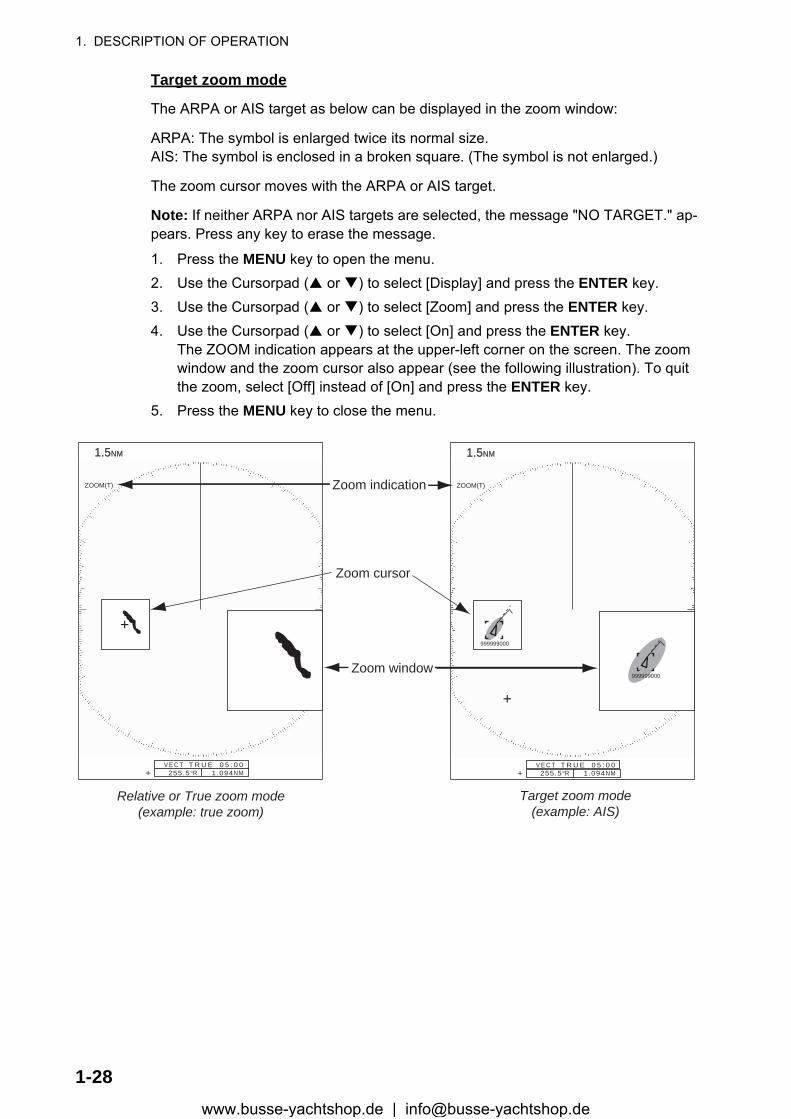
Target zoom mode
The ARPA or AIS target as below can be displayed in the zoom window:
ARPA: The symbol is enlarged twice its normal size.AIS: The symbol is enclosed in a broken square. (The symbol is not enlarged.)
The zoom cursor moves with the ARPA or AIS target.
Note: If neither ARPA nor AIS targets are selected, the message "NO TARGET." ap-pears. Press any key to erase the message.
1. Press the MENU key to open the menu.2. Use the Cursorpad ( or ) to select [Display] and press the ENTER key.3. Use the Cursorpad ( or ) to select [Zoom] and press the ENTER key.4. Use the Cursorpad ( or ) to select [On] and press the ENTER key.
The ZOOM indication appears at the upper-left corner on the screen. The zoom window and the zoom cursor also appear (see the following illustration). To quit the zoom, select [Off] instead of [On] and press the ENTER key.
5. Press the MENU key to close the menu.
1.51.5NMNM
Zoom window
255.5°R 1.094NM
ZOOM(T)
+
Zoom cursor
Zoom indication
V E C T T R U E 0 5 : 0 0+
1.51.5NMNM
255.5°R 1.094NM
ZOOM(T)
+
V E C T T R U E 0 5 : 0 0+
Relative or True zoom mode(example: true zoom)
Target zoom mode(example: AIS)
999999000
999999000
1-28www.busse-yachtshop.de | [email protected]
1. DESCRIPTION OF OPERATION
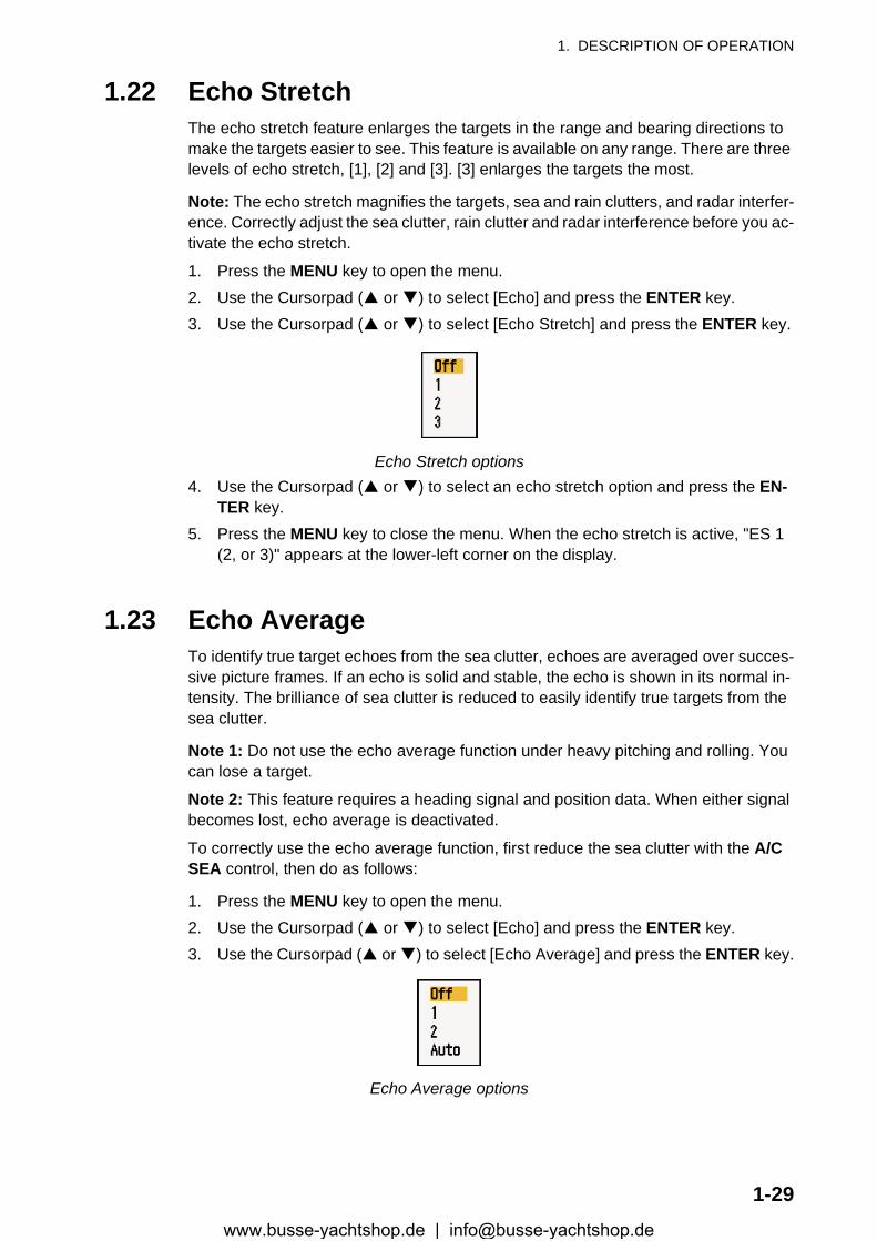
1.22 Echo StretchThe echo stretch feature enlarges the targets in the range and bearing directions to make the targets easier to see. This feature is available on any range. There are three levels of echo stretch, [1], [2] and [3]. [3] enlarges the targets the most.
Note: The echo stretch magnifies the targets, sea and rain clutters, and radar interfer-ence. Correctly adjust the sea clutter, rain clutter and radar interference before you ac-tivate the echo stretch.
1. Press the MENU key to open the menu.2. Use the Cursorpad ( or ) to select [Echo] and press the ENTER key.3. Use the Cursorpad ( or ) to select [Echo Stretch] and press the ENTER key.
Echo Stretch options4. Use the Cursorpad ( or ) to select an echo stretch option and press the EN-
TER key.5. Press the MENU key to close the menu. When the echo stretch is active, "ES 1
(2, or 3)" appears at the lower-left corner on the display.
1.23 Echo AverageTo identify true target echoes from the sea clutter, echoes are averaged over succes-sive picture frames. If an echo is solid and stable, the echo is shown in its normal in-tensity. The brilliance of sea clutter is reduced to easily identify true targets from the sea clutter.
Note 1: Do not use the echo average function under heavy pitching and rolling. You can lose a target.
Note 2: This feature requires a heading signal and position data. When either signal becomes lost, echo average is deactivated.
To correctly use the echo average function, first reduce the sea clutter with the A/C SEA control, then do as follows:
1. Press the MENU key to open the menu.2. Use the Cursorpad ( or ) to select [Echo] and press the ENTER key.3. Use the Cursorpad ( or ) to select [Echo Average] and press the ENTER key.
Echo Average options
1-29www.busse-yachtshop.de | [email protected]
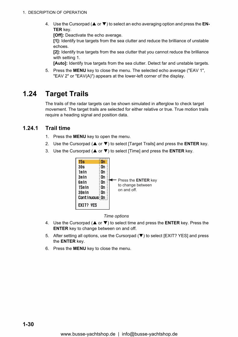
1. DESCRIPTION OF OPERATION
4. Use the Cursorpad ( or ) to select an echo averaging option and press the EN-TER key.[Off]: Deactivate the echo average.[1]: Identify true targets from the sea clutter and reduce the brilliance of unstable echoes.[2]: Identify true targets from the sea clutter that you cannot reduce the brilliance with setting 1.[Auto]: Identify true targets from the sea clutter. Detect far and unstable targets.
5. Press the MENU key to close the menu. The selected echo average ("EAV 1", "EAV 2" or "EAV(A)") appears at the lower-left corner of the display.
1.24 Target TrailsThe trails of the radar targets can be shown simulated in afterglow to check target movement. The target trails are selected for either relative or true. True motion trails require a heading signal and position data.
1.24.1 Trail time1. Press the MENU key to open the menu.2. Use the Cursorpad ( or ) to select [Target Trails] and press the ENTER key.3. Use the Cursorpad ( or ) to select [Time] and press the ENTER key.
Time options4. Use the Cursorpad ( or ) to select time and press the ENTER key. Press the
ENTER key to change between on and off.5. After setting all options, use the Cursorpad ( ) to select [EXIT? YES] and press
the ENTER key.6. Press the MENU key to close the menu.
Press the ENTER keyto change betweenon and off.
1-30www.busse-yachtshop.de | [email protected]
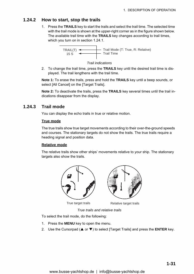
1. DESCRIPTION OF OPERATION
1.24.2 How to start, stop the trails1. Press the TRAILS key to start the trails and select the trail time. The selected time
with the trail mode is shown at the upper-right corner as in the figure shown below. The available trail time with the TRAILS key changes according to trail times, which you turn on in section 1.24.1.
Trail indications2. To change the trail time, press the TRAILS key until the desired trail time is dis-
played. The trail lengthens with the trail time.
Note 1: To erase the trails, press and hold the TRAILS key until a beep sounds, or select [All Cancel] on the [Target Trails].
Note 2: To deactivate the trails, press the TRAILS key several times until the trail in-dications disappear from the display.
1.24.3 Trail modeYou can display the echo trails in true or relative motion.
True mode
The true trails show true target movements according to their over-the-ground speeds and courses. The stationary targets do not show the trails. The true trails require a heading signal and position data.
Relative mode
The relative trails show other ships’ movements relative to your ship. The stationary targets also show the trails.
True trails and relative trails
To select the trail mode, do the following:
1. Press the MENU key to open the menu.2. Use the Cursorpad ( or ) to select [Target Trails] and press the ENTER key.
TRAIL(T)15 S
Trail Mode (T: True, R: Relative)Trail Time
True target trails Relative target trails
1-31www.busse-yachtshop.de | [email protected]
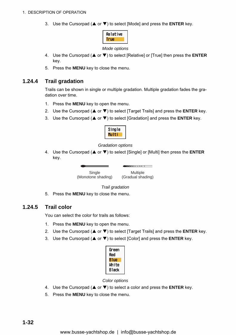
1. DESCRIPTION OF OPERATION
3. Use the Cursorpad ( or ) to select [Mode] and press the ENTER key.
Mode options4. Use the Cursorpad ( or ) to select [Relative] or [True] then press the ENTER
key.5. Press the MENU key to close the menu.
1.24.4 Trail gradationTrails can be shown in single or multiple gradation. Multiple gradation fades the gra-dation over time.
1. Press the MENU key to open the menu.2. Use the Cursorpad ( or ) to select [Target Trails] and press the ENTER key.3. Use the Cursorpad ( or ) to select [Gradation] and press the ENTER key.
Gradation options4. Use the Cursorpad ( or ) to select [Single] or [Multi] then press the ENTER
key.
Trail gradation5. Press the MENU key to close the menu.
1.24.5 Trail colorYou can select the color for trails as follows:
1. Press the MENU key to open the menu.2. Use the Cursorpad ( or ) to select [Target Trails] and press the ENTER key.3. Use the Cursorpad ( or ) to select [Color] and press the ENTER key.
Color options4. Use the Cursorpad ( or ) to select a color and press the ENTER key.5. Press the MENU key to close the menu.
Multiple(Gradual shading)
Single(Monotone shading)
1-32www.busse-yachtshop.de | [email protected]
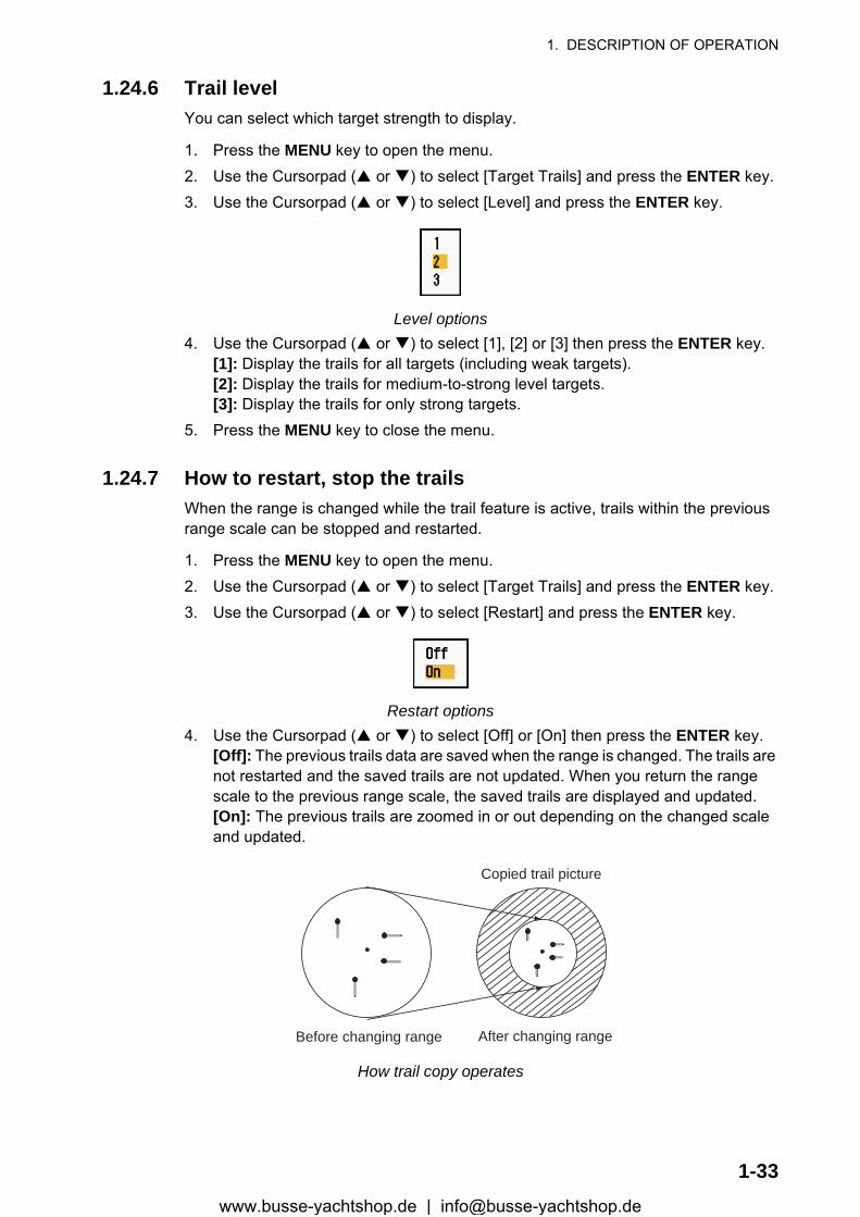
1. DESCRIPTION OF OPERATION
1.24.6 Trail levelYou can select which target strength to display.
1. Press the MENU key to open the menu.2. Use the Cursorpad ( or ) to select [Target Trails] and press the ENTER key.3. Use the Cursorpad ( or ) to select [Level] and press the ENTER key.
Level options4. Use the Cursorpad ( or ) to select [1], [2] or [3] then press the ENTER key.
[1]: Display the trails for all targets (including weak targets).[2]: Display the trails for medium-to-strong level targets.[3]: Display the trails for only strong targets.
5. Press the MENU key to close the menu.
1.24.7 How to restart, stop the trailsWhen the range is changed while the trail feature is active, trails within the previous range scale can be stopped and restarted.
1. Press the MENU key to open the menu.2. Use the Cursorpad ( or ) to select [Target Trails] and press the ENTER key.3. Use the Cursorpad ( or ) to select [Restart] and press the ENTER key.
Restart options4. Use the Cursorpad ( or ) to select [Off] or [On] then press the ENTER key.
[Off]: The previous trails data are saved when the range is changed. The trails are not restarted and the saved trails are not updated. When you return the range scale to the previous range scale, the saved trails are displayed and updated.[On]: The previous trails are zoomed in or out depending on the changed scale and updated.
How trail copy operates
Before changing range After changing range
Copied trail picture
1-33www.busse-yachtshop.de | [email protected]
1. DESCRIPTION OF OPERATION
Note: If the newly selected range is less than or equal to 1/4 of the previous range, trails are erased. If the newly selected range is longer than the previous range, the previous trails are left to be displayed.
5. Press the MENU key to close the menu.
1.24.8 Narrow trailsYou can display the target trails in thin trails. When there are many targets on the screen, you can separate trails close to one another with this function.
1. Press the MENU key to open the menu.2. Use the Cursorpad ( or ) to select [Target Trails] and press the ENTER key.3. Use the Cursorpad ( or ) to select [Narrow] and press the ENTER key.
Narrow options4. Use the Cursorpad ( or ) to select [Off] or [On] then press the ENTER key.5. Press the MENU key to close the menu.
1.24.9 Your ship trailYou can show the trail of your ship as follows:
1. Press the MENU key to open the menu.2. Use the Cursorpad ( or ) to select [Target Trails] and press the ENTER key.3. Use the Cursorpad ( or ) to select [Own Ship] and press the ENTER key.
Own Ship options4. Use the Cursorpad ( or ) to select [Off], [1] or [2] then press the ENTER key.
[Off]: Hide the trail of your ship.[1]: Show the trail of your ship.[2]: Show the trail of your ship, but hide the trail of sea clutter near your ship.
5. Press the MENU key to close the menu.
1.25 How to Send the Target PositionThe TLL key functions to send the cursor position to external navigator. Position and heading signal are required. Use the Cursorpad to put the cursor on a target and press the TLL key.
1-34www.busse-yachtshop.de | [email protected]

1. DESCRIPTION OF OPERATION
1.26 How to Hide the Heading Line TemporarilyThe heading line indicates the heading of your ship in all display modes. The heading line is a line from your ship position to the outer edge of the radar display area. The heading line appears at zero degrees on the bearing scale in head-up and true view modes. The heading line changes the orientation depending on the ship orientation in north-up and true motion modes and when the course is changed in the course-up mode.
To hide the heading line (and all marks for River and Sea purpose) and display only targets, press and hold the CANCEL/HL OFF key. To display the heading line again, release the key.
1.27 Presentation BrillianceYou can adjust the brilliance for the following menu items from the [Brill/Color] menu.
[Echo Brill]: Brilliance for the echoes (setting range: 1 - 8)
[Rings Brill]: Brilliance for the range rings (setting range: Off, 1 - 4)
[Mark Brill]: Brilliance for the marks (EBL, VRM, etc.) (setting range: 1 - 4)
[HL Brill]: Brilliance for the heading line (setting range: 1 - 4)
[Character Brill]: Brilliance for the characters (setting range: 1 - 4)
1.28 Custom Setup
1.28.1 About custom setupWhen your navigating environment or task changes, you must adjust the radar. In-stead of changing radar settings case by case, you can assign the CUSTOM key to provide best settings for common conditions.
There are three default custom setups for the internal computer of the radar (see the table on the next page). You can adjust these settings on the [Custom 1], [Custom 2] and [Custom 3] menus to meet your navigation needs.
To activate a custom setup, press the CUSTOM key. The CUSTOM key switches be-tween Custom 1, Custom 2 or Custom 3 each time you press the key. (Custom setup numbers which are turned off are ignored.) The selected custom setup name is shown at the upper-left corner. To escape from custom setup, operate any control.
1-35www.busse-yachtshop.de | [email protected]
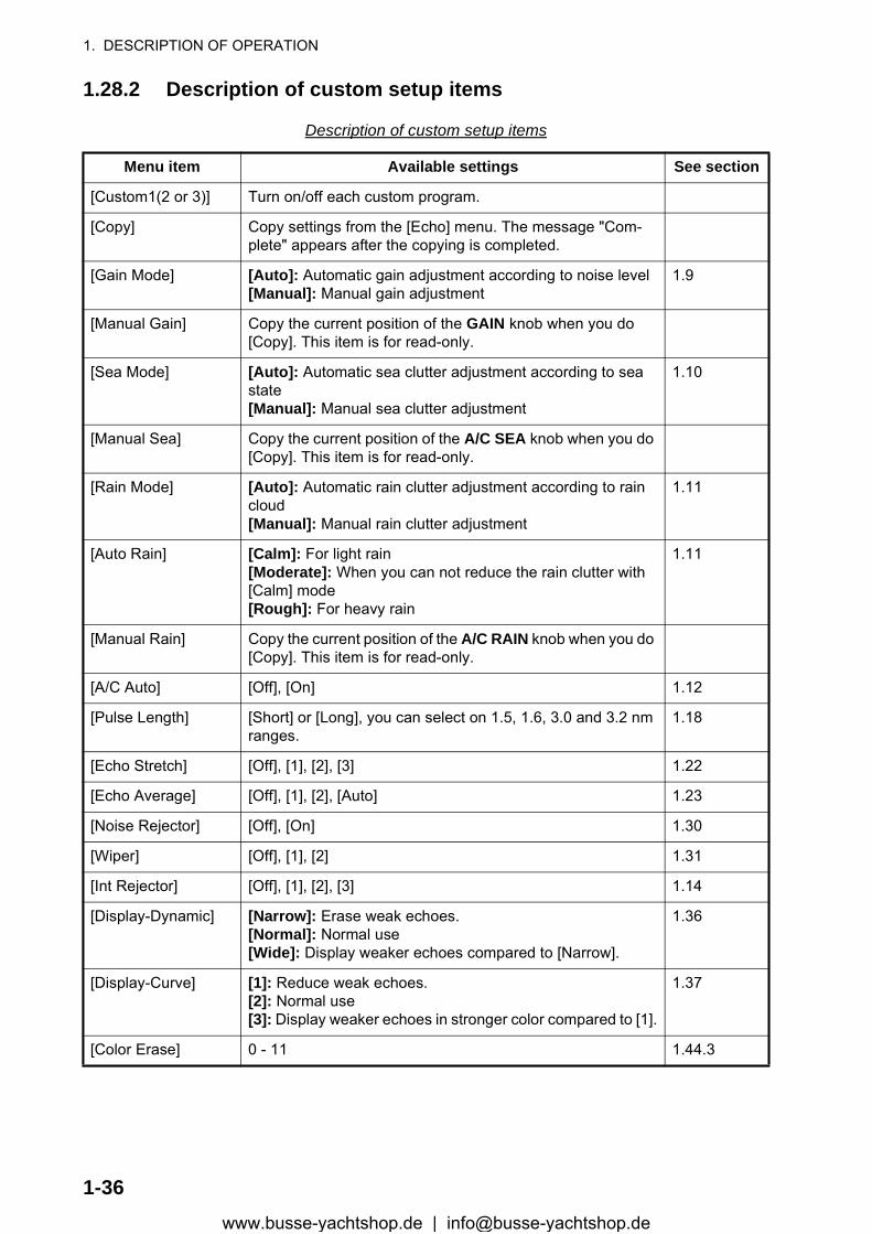
1. DESCRIPTION OF OPERATION
1.28.2 Description of custom setup items
Description of custom setup items
Menu item Available settings See section
[Custom1(2 or 3)] Turn on/off each custom program.
[Copy] Copy settings from the [Echo] menu. The message "Com-plete" appears after the copying is completed.
[Gain Mode] [Auto]: Automatic gain adjustment according to noise level[Manual]: Manual gain adjustment
1.9
[Manual Gain] Copy the current position of the GAIN knob when you do [Copy]. This item is for read-only.
[Sea Mode] [Auto]: Automatic sea clutter adjustment according to sea state[Manual]: Manual sea clutter adjustment
1.10
[Manual Sea] Copy the current position of the A/C SEA knob when you do [Copy]. This item is for read-only.
[Rain Mode] [Auto]: Automatic rain clutter adjustment according to rain cloud[Manual]: Manual rain clutter adjustment
1.11
[Auto Rain] [Calm]: For light rain[Moderate]: When you can not reduce the rain clutter with [Calm] mode[Rough]: For heavy rain
1.11
[Manual Rain] Copy the current position of the A/C RAIN knob when you do [Copy]. This item is for read-only.
[A/C Auto] [Off], [On] 1.12
[Pulse Length] [Short] or [Long], you can select on 1.5, 1.6, 3.0 and 3.2 nm ranges.
1.18
[Echo Stretch] [Off], [1], [2], [3] 1.22
[Echo Average] [Off], [1], [2], [Auto] 1.23
[Noise Rejector] [Off], [On] 1.30
[Wiper] [Off], [1], [2] 1.31
[Int Rejector] [Off], [1], [2], [3] 1.14
[Display-Dynamic] [Narrow]: Erase weak echoes.[Normal]: Normal use[Wide]: Display weaker echoes compared to [Narrow].
1.36
[Display-Curve] [1]: Reduce weak echoes.[2]: Normal use[3]: Display weaker echoes in stronger color compared to [1].
1.37
[Color Erase] 0 - 11 1.44.3
1-36www.busse-yachtshop.de | [email protected]
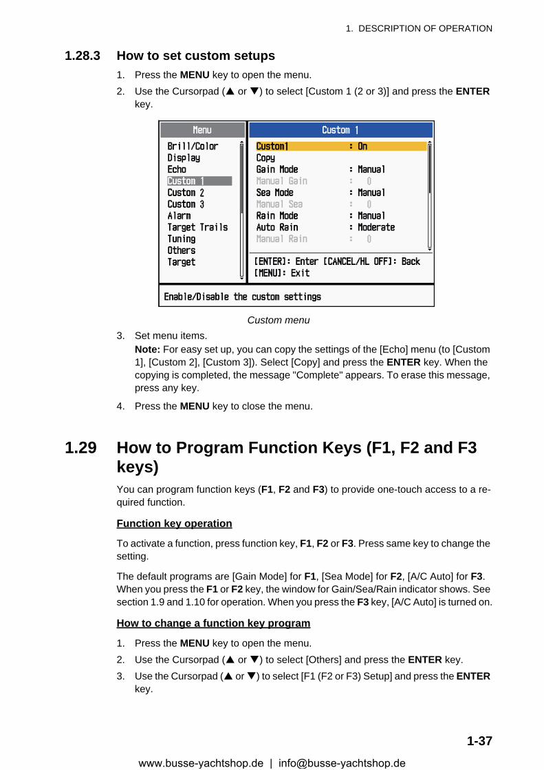
1. DESCRIPTION OF OPERATION
1.28.3 How to set custom setups1. Press the MENU key to open the menu.2. Use the Cursorpad ( or ) to select [Custom 1 (2 or 3)] and press the ENTER
key.
Custom menu3. Set menu items.
Note: For easy set up, you can copy the settings of the [Echo] menu (to [Custom 1], [Custom 2], [Custom 3]). Select [Copy] and press the ENTER key. When the copying is completed, the message "Complete" appears. To erase this message, press any key.
4. Press the MENU key to close the menu.
1.29 How to Program Function Keys (F1, F2 and F3 keys)You can program function keys (F1, F2 and F3) to provide one-touch access to a re-quired function.
Function key operation
To activate a function, press function key, F1, F2 or F3. Press same key to change the setting.
The default programs are [Gain Mode] for F1, [Sea Mode] for F2, [A/C Auto] for F3. When you press the F1 or F2 key, the window for Gain/Sea/Rain indicator shows. See section 1.9 and 1.10 for operation. When you press the F3 key, [A/C Auto] is turned on.
How to change a function key program
1. Press the MENU key to open the menu.2. Use the Cursorpad ( or ) to select [Others] and press the ENTER key.3. Use the Cursorpad ( or ) to select [F1 (F2 or F3) Setup] and press the ENTER
key.
1-37www.busse-yachtshop.de | [email protected]
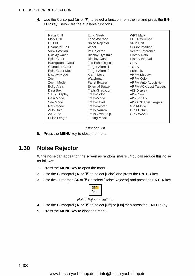
1. DESCRIPTION OF OPERATION
4. Use the Cursorpad ( or ) to select a function from the list and press the EN-TER key. Below are the available functions.
Function list5. Press the MENU key to close the menu.
1.30 Noise RejectorWhite noise can appear on the screen as random "marks". You can reduce this noise as follows:
1. Press the MENU key to open the menu.2. Use the Cursorpad ( or ) to select [Echo] and press the ENTER key.3. Use the Cursorpad ( or ) to select [Noise Rejector] and press the ENTER key.
Noise Rejector options4. Use the Cursorpad ( or ) to select [Off] or [On] then press the ENTER key.5. Press the MENU key to close the menu.
Rings BrillMark BrillHL BrillCharacter BrillView PositionDisplay ColorEcho ColorBackground ColorCharacter ColorEcho Color ModeDisplay ModeZoomZoom ModeEcho AreaData BoxSTBY DisplayGain ModeSea ModeRain ModeAuto RainA/C AutoPulse Length
Echo StretchEcho AverageNoise RejectorWiperInt RejectorDisplay-DynamicDisplay-Curve2nd Echo RejectorTarget Alarm 1Target Alarm 2Alarm LevelWatchmanPanel BuzzerExternal BuzzerTrails-GradationTrails-ColorTrails-ModeTrails-LevelTrails-RestartTrails-NarrowTrails-Own ShipTuning Mode
WPT MarkEBL ReferenceVRM UnitCursor PositionVector ReferenceHistory DotsHistory IntervalCPATCPAProximityARPA-DisplayARPA-ColorARPA-Auto AcquisitionARPA-ACK Lost TargetsAIS-DisplayAIS-ColorAIS-Sort ByAIS-ACK Lost TargetsGPS-ModeGPS-DatumGPS-WAAS
1-38www.busse-yachtshop.de | [email protected]

1. DESCRIPTION OF OPERATION
1.31 WiperThe wiper feature automatically reduces the brilliance of unwanted weak signals (noise, sea clutter, rain clutter, etc.) and unnecessary signals, like radar interference, to clear the picture of unnecessary echoes. The result of wiper depends on the wiper setting used and whether echo averaging is turned on or off, as described below.
Echo averaging and wiper states and wiper effect
Processing content A: The brilliance of unnecessary weak echoes, like noise and radar interference, is reduced to clear the picture. The difference between wiper 1 and 2 is that brilliance is lowered more slowly in 1.
Processing content B: Echo averaging is automatically turned on from off when the wiper feature is turned on. You can see how the picture changes with the echo aver-aging turned off and turned on.
To activate the wiper feature, do the following:
1. Press the MENU key to open the menu.2. Use the Cursorpad ( or ) to select [Echo] and press the ENTER key.3. Use the Cursorpad ( or ) to select [Wiper] and press the ENTER key.
Wiper options4. Use the Cursorpad ( or ) to select [1] or [2] then press the ENTER key.5. Press the MENU key to close the menu.
Note: When the [Display Mode] is [True View], this function is not available (see sec-tion 1.7.2).
1.32 How to Reduce Second-trace EchoesEchoes from very distant targets can appear as false echoes (second-trace echoes) on the screen. The second-trace echo occurs when the return echo is received one transmission cycle later, or after a next transmission of radar pulse.
Second-trace echoes
Wiper 1 Wiper 2
Echo Average Off Processing content A
Echo Average On (1, 2, Auto) Processing content A Processing content B
Second-traceecho
TX repetition
Actual range
False echorange
1-39www.busse-yachtshop.de | [email protected]
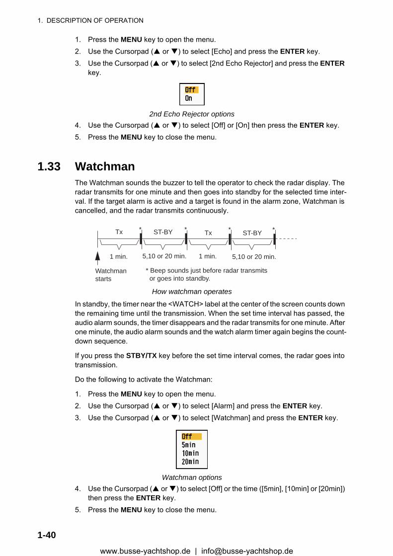
1. DESCRIPTION OF OPERATION
1. Press the MENU key to open the menu.2. Use the Cursorpad ( or ) to select [Echo] and press the ENTER key.3. Use the Cursorpad ( or ) to select [2nd Echo Rejector] and press the ENTER
key.
2nd Echo Rejector options4. Use the Cursorpad ( or ) to select [Off] or [On] then press the ENTER key.5. Press the MENU key to close the menu.
1.33 WatchmanThe Watchman sounds the buzzer to tell the operator to check the radar display. The radar transmits for one minute and then goes into standby for the selected time inter-val. If the target alarm is active and a target is found in the alarm zone, Watchman is cancelled, and the radar transmits continuously.
How watchman operates
In standby, the timer near the <WATCH> label at the center of the screen counts down the remaining time until the transmission. When the set time interval has passed, the audio alarm sounds, the timer disappears and the radar transmits for one minute. After one minute, the audio alarm sounds and the watch alarm timer again begins the count-down sequence.
If you press the STBY/TX key before the set time interval comes, the radar goes into transmission.
Do the following to activate the Watchman:
1. Press the MENU key to open the menu.2. Use the Cursorpad ( or ) to select [Alarm] and press the ENTER key.3. Use the Cursorpad ( or ) to select [Watchman] and press the ENTER key.
Watchman options4. Use the Cursorpad ( or ) to select [Off] or the time ([5min], [10min] or [20min])
then press the ENTER key.5. Press the MENU key to close the menu.
ST-BY
5,10 or 20 min.
Tx
1 min.
Watchmanstarts
*
* Beep sounds just before radar transmits or goes into standby.
ST-BY Tx *
5,10 or 20 min.1 min.
* *
1-40www.busse-yachtshop.de | [email protected]
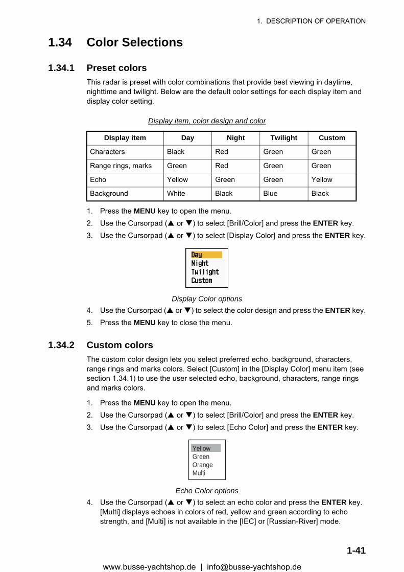
1. DESCRIPTION OF OPERATION
1.34 Color Selections
1.34.1 Preset colorsThis radar is preset with color combinations that provide best viewing in daytime, nighttime and twilight. Below are the default color settings for each display item and display color setting.
Display item, color design and color
1. Press the MENU key to open the menu.2. Use the Cursorpad ( or ) to select [Brill/Color] and press the ENTER key.3. Use the Cursorpad ( or ) to select [Display Color] and press the ENTER key.
Display Color options4. Use the Cursorpad ( or ) to select the color design and press the ENTER key.5. Press the MENU key to close the menu.
1.34.2 Custom colorsThe custom color design lets you select preferred echo, background, characters, range rings and marks colors. Select [Custom] in the [Display Color] menu item (see section 1.34.1) to use the user selected echo, background, characters, range rings and marks colors.
1. Press the MENU key to open the menu.2. Use the Cursorpad ( or ) to select [Brill/Color] and press the ENTER key.3. Use the Cursorpad ( or ) to select [Echo Color] and press the ENTER key.
Echo Color options4. Use the Cursorpad ( or ) to select an echo color and press the ENTER key.
[Multi] displays echoes in colors of red, yellow and green according to echo strength, and [Multi] is not available in the [IEC] or [Russian-River] mode.
DIsplay item Day Night Twilight Custom
Characters Black Red Green Green
Range rings, marks Green Red Green Green
Echo Yellow Green Green Yellow
Background White Black Blue Black
YellowGreenOrangeMulti
1-41www.busse-yachtshop.de | [email protected]
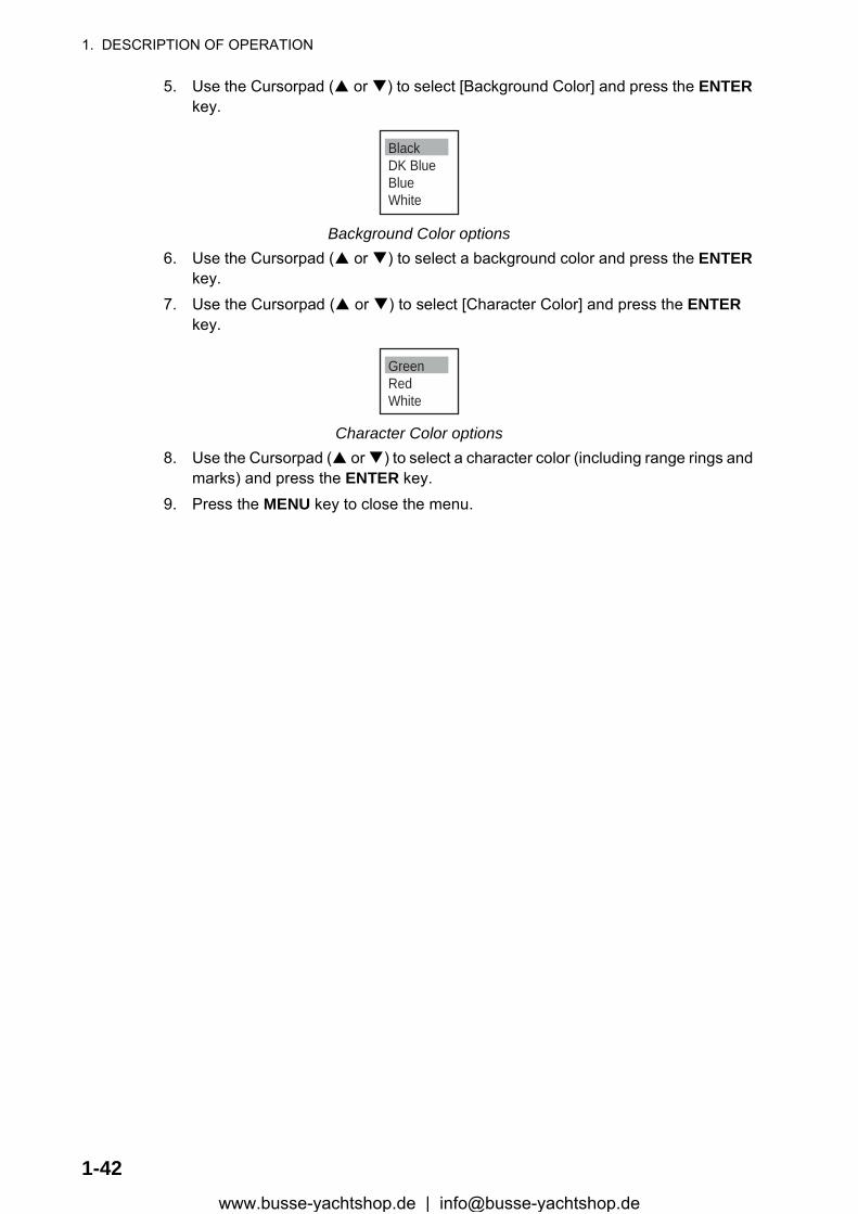
1. DESCRIPTION OF OPERATION
5. Use the Cursorpad ( or ) to select [Background Color] and press the ENTER key.
Background Color options6. Use the Cursorpad ( or ) to select a background color and press the ENTER
key.7. Use the Cursorpad ( or ) to select [Character Color] and press the ENTER
key.
Character Color options8. Use the Cursorpad ( or ) to select a character color (including range rings and
marks) and press the ENTER key.9. Press the MENU key to close the menu.
BlackDK BlueBlueWhite
GreenRedWhite
1-42www.busse-yachtshop.de | [email protected]
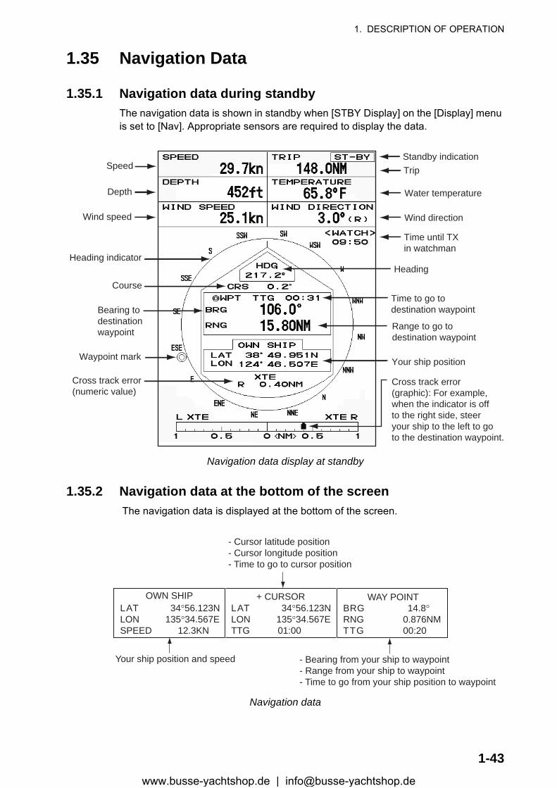
1. DESCRIPTION OF OPERATION
1.35 Navigation Data
1.35.1 Navigation data during standbyThe navigation data is shown in standby when [STBY Display] on the [Display] menu is set to [Nav]. Appropriate sensors are required to display the data.
Navigation data display at standby
1.35.2 Navigation data at the bottom of the screen The navigation data is displayed at the bottom of the screen.
Navigation data
SpeedStandby indication
Depth Water temperature
Trip
Wind speed Wind direction
Time until TXin watchman
Heading indicatorHeading
CourseTime to go todestination waypointBearing to
destinationwaypoint Range to go to
destination waypoint
Waypoint mark Your ship position
Cross track error(numeric value)
Cross track error(graphic): For example,when the indicator is offto the right side, steeryour ship to the left to goto the destination waypoint.
- Cursor latitude position- Cursor longitude position- Time to go to cursor position
Your ship position and speed - Bearing from your ship to waypoint- Range from your ship to waypoint- Time to go from your ship position to waypoint
LAT 34°56.123NLON 135°34.567ESPEED 12.3KN
LAT 34°56.123NLON 135°34.567ETTG 01:00
BRG 14.8°RNG 0.876NMTTG 00:20
OWN SHIP + CURSOR WAY POINT
1-43www.busse-yachtshop.de | [email protected]
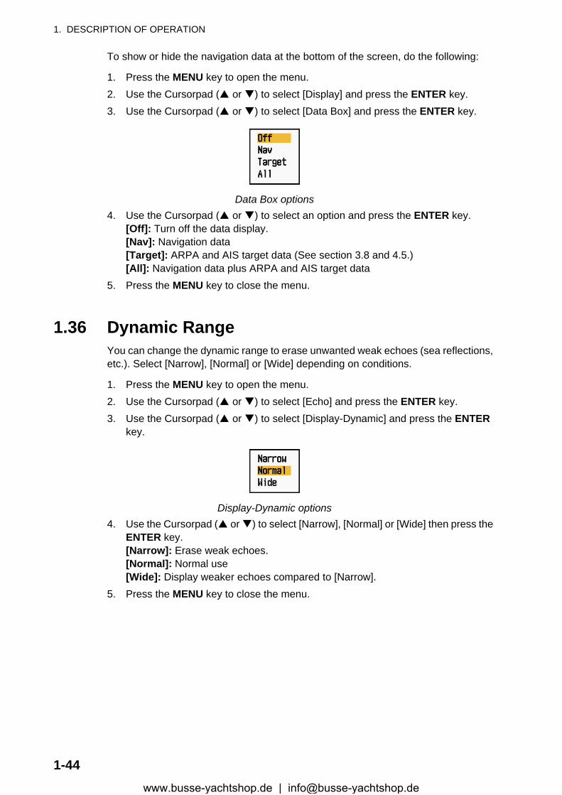
1. DESCRIPTION OF OPERATION
To show or hide the navigation data at the bottom of the screen, do the following:
1. Press the MENU key to open the menu.2. Use the Cursorpad ( or ) to select [Display] and press the ENTER key.3. Use the Cursorpad ( or ) to select [Data Box] and press the ENTER key.
Data Box options4. Use the Cursorpad ( or ) to select an option and press the ENTER key.
[Off]: Turn off the data display.[Nav]: Navigation data[Target]: ARPA and AIS target data (See section 3.8 and 4.5.)[All]: Navigation data plus ARPA and AIS target data
5. Press the MENU key to close the menu.
1.36 Dynamic RangeYou can change the dynamic range to erase unwanted weak echoes (sea reflections, etc.). Select [Narrow], [Normal] or [Wide] depending on conditions.
1. Press the MENU key to open the menu.2. Use the Cursorpad ( or ) to select [Echo] and press the ENTER key.3. Use the Cursorpad ( or ) to select [Display-Dynamic] and press the ENTER
key.
Display-Dynamic options4. Use the Cursorpad ( or ) to select [Narrow], [Normal] or [Wide] then press the
ENTER key.[Narrow]: Erase weak echoes.[Normal]: Normal use[Wide]: Display weaker echoes compared to [Narrow].
5. Press the MENU key to close the menu.
1-44www.busse-yachtshop.de | [email protected]
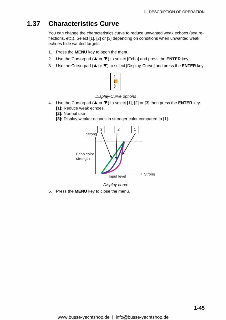
1. DESCRIPTION OF OPERATION
1.37 Characteristics CurveYou can change the characteristics curve to reduce unwanted weak echoes (sea re-flections, etc.). Select [1], [2] or [3] depending on conditions when unwanted weak echoes hide wanted targets.
1. Press the MENU key to open the menu.2. Use the Cursorpad ( or ) to select [Echo] and press the ENTER key.3. Use the Cursorpad ( or ) to select [Display-Curve] and press the ENTER key.
Display-Curve options4. Use the Cursorpad ( or ) to select [1], [2] or [3] then press the ENTER key.
[1]: Reduce weak echoes.[2]: Normal use[3]: Display weaker echoes in stronger color compared to [1].
Display curve5. Press the MENU key to close the menu.
3 2 1
Input level
Echo colorstrength
Strong
Strong
1-45www.busse-yachtshop.de | [email protected]
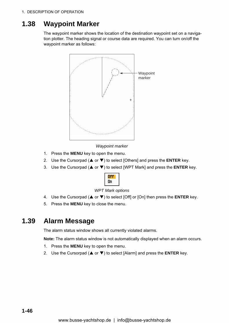
1. DESCRIPTION OF OPERATION
1.38 Waypoint MarkerThe waypoint marker shows the location of the destination waypoint set on a naviga-tion plotter. The heading signal or course data are required. You can turn on/off the waypoint marker as follows:
Waypoint marker
1. Press the MENU key to open the menu.2. Use the Cursorpad ( or ) to select [Others] and press the ENTER key.3. Use the Cursorpad ( or ) to select [WPT Mark] and press the ENTER key.
WPT Mark options4. Use the Cursorpad ( or ) to select [Off] or [On] then press the ENTER key.5. Press the MENU key to close the menu.
1.39 Alarm MessageThe alarm status window shows all currently violated alarms.
Note: The alarm status window is not automatically displayed when an alarm occurs.
1. Press the MENU key to open the menu.2. Use the Cursorpad ( or ) to select [Alarm] and press the ENTER key.
+
Waypointmarker
1-46www.busse-yachtshop.de | [email protected]
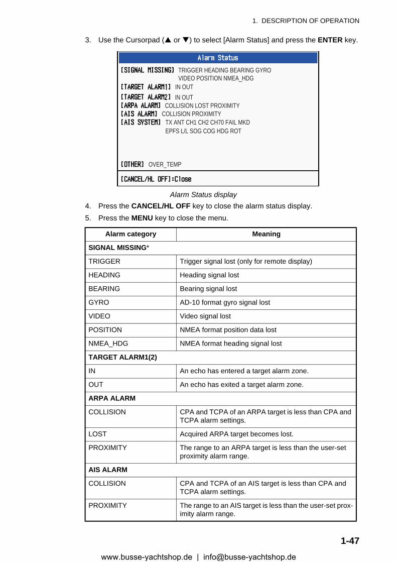
1. DESCRIPTION OF OPERATION
3. Use the Cursorpad ( or ) to select [Alarm Status] and press the ENTER key.
Alarm Status display4. Press the CANCEL/HL OFF key to close the alarm status display.5. Press the MENU key to close the menu.
Alarm category Meaning
SIGNAL MISSING*
TRIGGER Trigger signal lost (only for remote display)
HEADING Heading signal lost
BEARING Bearing signal lost
GYRO AD-10 format gyro signal lost
VIDEO Video signal lost
POSITION NMEA format position data lost
NMEA_HDG NMEA format heading signal lost
TARGET ALARM1(2)
IN An echo has entered a target alarm zone.
OUT An echo has exited a target alarm zone.
ARPA ALARM
COLLISION CPA and TCPA of an ARPA target is less than CPA and TCPA alarm settings.
LOST Acquired ARPA target becomes lost.
PROXIMITY The range to an ARPA target is less than the user-set proximity alarm range.
AIS ALARM
COLLISION CPA and TCPA of an AIS target is less than CPA and TCPA alarm settings.
PROXIMITY The range to an AIS target is less than the user-set prox-imity alarm range.
TRIGGER HEADING BEARING GYROVIDEO POSITION NMEA_HDG
IN OUTIN OUT
COLLISION LOST PROXIMITYCOLLISION PROXIMITY
TX ANT CH1 CH2 CH70 FAIL MKDEPFS L/L SOG COG HDG ROT
OVER_TEMP
1-47www.busse-yachtshop.de | [email protected]
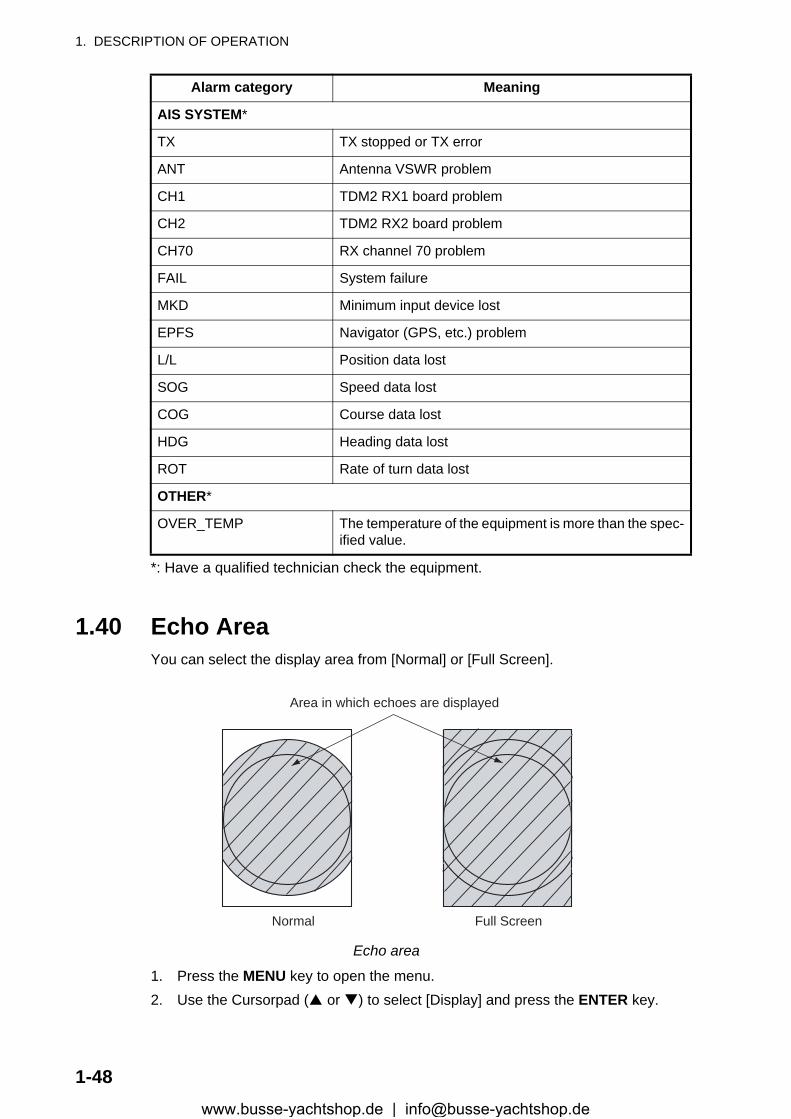
1. DESCRIPTION OF OPERATION
*: Have a qualified technician check the equipment.
1.40 Echo AreaYou can select the display area from [Normal] or [Full Screen].
Echo area
1. Press the MENU key to open the menu.2. Use the Cursorpad ( or ) to select [Display] and press the ENTER key.
AIS SYSTEM*
TX TX stopped or TX error
ANT Antenna VSWR problem
CH1 TDM2 RX1 board problem
CH2 TDM2 RX2 board problem
CH70 RX channel 70 problem
FAIL System failure
MKD Minimum input device lost
EPFS Navigator (GPS, etc.) problem
L/L Position data lost
SOG Speed data lost
COG Course data lost
HDG Heading data lost
ROT Rate of turn data lost
OTHER*
OVER_TEMP The temperature of the equipment is more than the spec-ified value.
Alarm category Meaning
Normal Full Screen
Area in which echoes are displayed
1-48www.busse-yachtshop.de | [email protected]
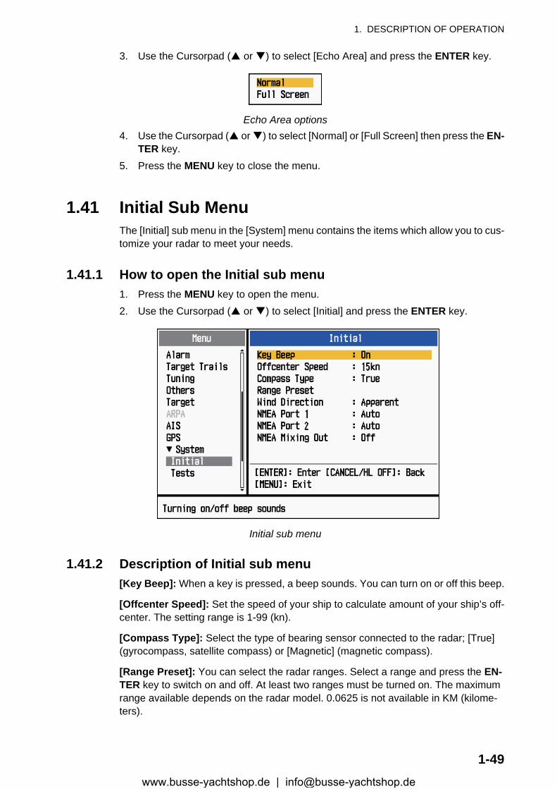
1. DESCRIPTION OF OPERATION
3. Use the Cursorpad ( or ) to select [Echo Area] and press the ENTER key.
Echo Area options4. Use the Cursorpad ( or ) to select [Normal] or [Full Screen] then press the EN-
TER key.5. Press the MENU key to close the menu.
1.41 Initial Sub MenuThe [Initial] sub menu in the [System] menu contains the items which allow you to cus-tomize your radar to meet your needs.
1.41.1 How to open the Initial sub menu1. Press the MENU key to open the menu.2. Use the Cursorpad ( or ) to select [Initial] and press the ENTER key.
Initial sub menu
1.41.2 Description of Initial sub menu[Key Beep]: When a key is pressed, a beep sounds. You can turn on or off this beep.
[Offcenter Speed]: Set the speed of your ship to calculate amount of your ship’s off-center. The setting range is 1-99 (kn).
[Compass Type]: Select the type of bearing sensor connected to the radar; [True] (gyrocompass, satellite compass) or [Magnetic] (magnetic compass).
[Range Preset]: You can select the radar ranges. Select a range and press the EN-TER key to switch on and off. At least two ranges must be turned on. The maximum range available depends on the radar model. 0.0625 is not available in KM (kilome-ters).
1-49www.busse-yachtshop.de | [email protected]
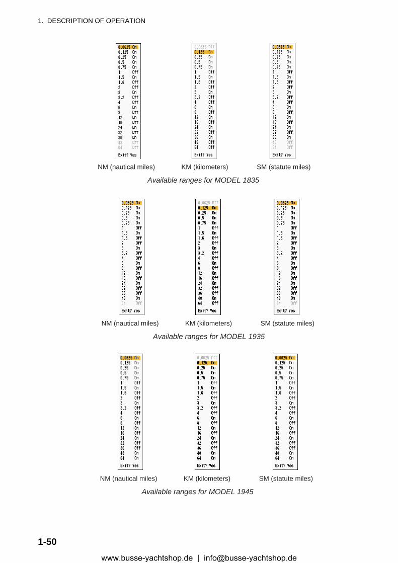
1. DESCRIPTION OF OPERATION
NM (nautical miles) KM (kilometers) SM (statute miles)
Available ranges for MODEL 1835
NM (nautical miles) KM (kilometers) SM (statute miles)
Available ranges for MODEL 1935
NM (nautical miles) KM (kilometers) SM (statute miles)
Available ranges for MODEL 1945
1-50www.busse-yachtshop.de | [email protected]
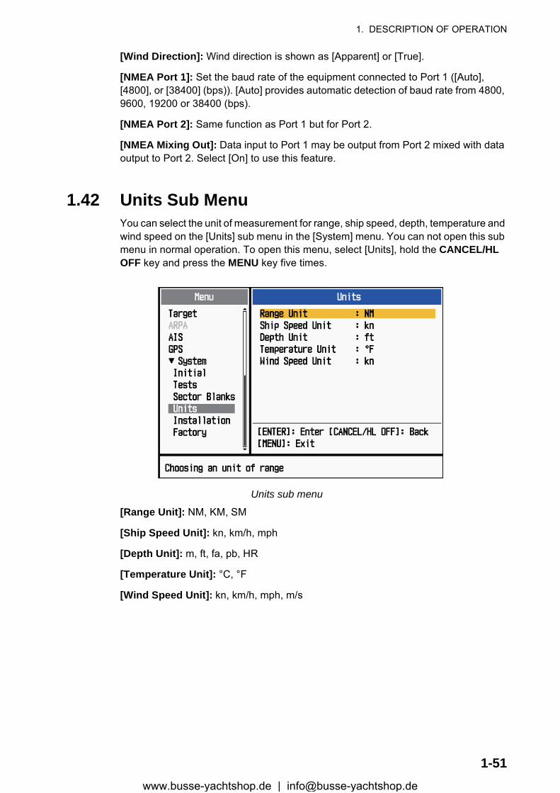
1. DESCRIPTION OF OPERATION
[Wind Direction]: Wind direction is shown as [Apparent] or [True].
[NMEA Port 1]: Set the baud rate of the equipment connected to Port 1 ([Auto], [4800], or [38400] (bps)). [Auto] provides automatic detection of baud rate from 4800, 9600, 19200 or 38400 (bps).
[NMEA Port 2]: Same function as Port 1 but for Port 2.
[NMEA Mixing Out]: Data input to Port 1 may be output from Port 2 mixed with data output to Port 2. Select [On] to use this feature.
1.42 Units Sub MenuYou can select the unit of measurement for range, ship speed, depth, temperature and wind speed on the [Units] sub menu in the [System] menu. You can not open this sub menu in normal operation. To open this menu, select [Units], hold the CANCEL/HL OFF key and press the MENU key five times.
Units sub menu
[Range Unit]: NM, KM, SM
[Ship Speed Unit]: kn, km/h, mph
[Depth Unit]: m, ft, fa, pb, HR
[Temperature Unit]: °C, °F
[Wind Speed Unit]: kn, km/h, mph, m/s
1-51www.busse-yachtshop.de | [email protected]
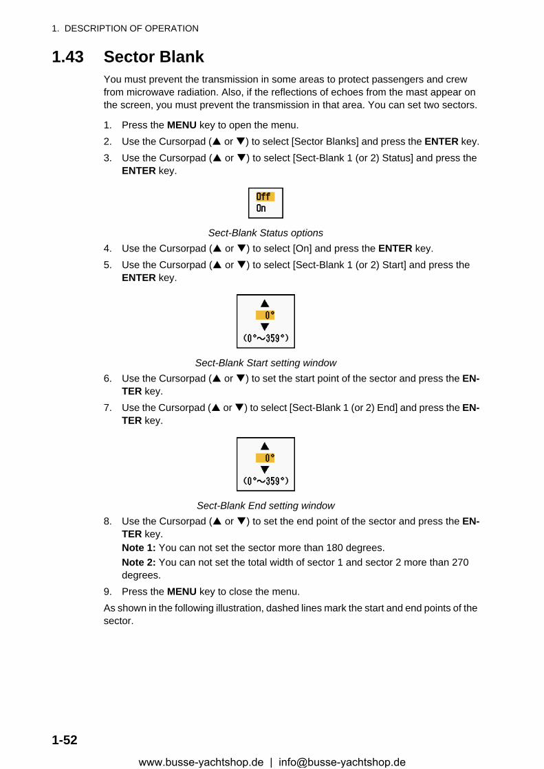
1. DESCRIPTION OF OPERATION
1.43 Sector BlankYou must prevent the transmission in some areas to protect passengers and crew from microwave radiation. Also, if the reflections of echoes from the mast appear on the screen, you must prevent the transmission in that area. You can set two sectors.
1. Press the MENU key to open the menu.2. Use the Cursorpad ( or ) to select [Sector Blanks] and press the ENTER key.3. Use the Cursorpad ( or ) to select [Sect-Blank 1 (or 2) Status] and press the
ENTER key.
Sect-Blank Status options4. Use the Cursorpad ( or ) to select [On] and press the ENTER key.5. Use the Cursorpad ( or ) to select [Sect-Blank 1 (or 2) Start] and press the
ENTER key.
Sect-Blank Start setting window6. Use the Cursorpad ( or ) to set the start point of the sector and press the EN-
TER key.7. Use the Cursorpad ( or ) to select [Sect-Blank 1 (or 2) End] and press the EN-
TER key.
Sect-Blank End setting window8. Use the Cursorpad ( or ) to set the end point of the sector and press the EN-
TER key.Note 1: You can not set the sector more than 180 degrees.Note 2: You can not set the total width of sector 1 and sector 2 more than 270 degrees.
9. Press the MENU key to close the menu.As shown in the following illustration, dashed lines mark the start and end points of the sector.
1-52www.busse-yachtshop.de | [email protected]
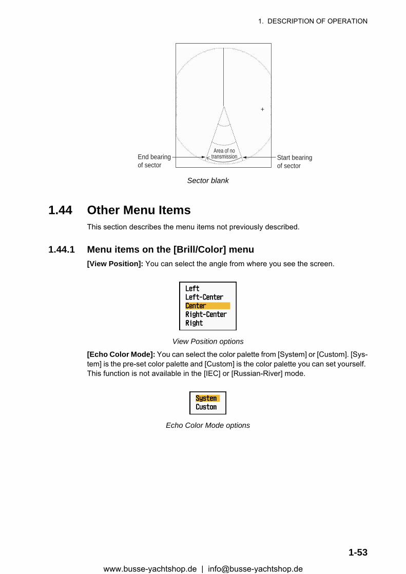
1. DESCRIPTION OF OPERATION
Sector blank
1.44 Other Menu ItemsThis section describes the menu items not previously described.
1.44.1 Menu items on the [Brill/Color] menu[View Position]: You can select the angle from where you see the screen.
View Position options
[Echo Color Mode]: You can select the color palette from [System] or [Custom]. [Sys-tem] is the pre-set color palette and [Custom] is the color palette you can set yourself. This function is not available in the [IEC] or [Russian-River] mode.
Echo Color Mode options
+
Area of notransmission Start bearing
of sectorEnd bearingof sector
1-53www.busse-yachtshop.de | [email protected]

1. DESCRIPTION OF OPERATION
[Custom Echo Color]: You can customize the echo color with the following two meth-ods. This function is not available in the [IEC] or [Russian-River] mode.
Custom Echo Color setting window
Method 1: 1) Select the echo rank to change on the [Rank] (setting range: 1 - 31).2) Set the RGB values for selected echo rank on the [Red], [Green] and
[Blue] (setting range: 0 - 63).
Method 2: 1) Select 31 on the [Rank].2) Set the RGB values for 31 echo rank on the [Red], [Green] and [Blue]
(setting range: 0 - 63).3) Interpolate the RGB values between the maximum rank and minimum
rank on the [Fitting To Curve] with the following curves (setting range: -20 to 20). Setting range > 0: Logarithmic curve, useful to emphasize the weak
echoes. Setting range = 0: Straight line Setting range < 0: Exponential curve, useful to emphasize the strong
echoes.
[Copy To Custom]: Copy the color palette from [System] to [Custom].
1-54www.busse-yachtshop.de | [email protected]
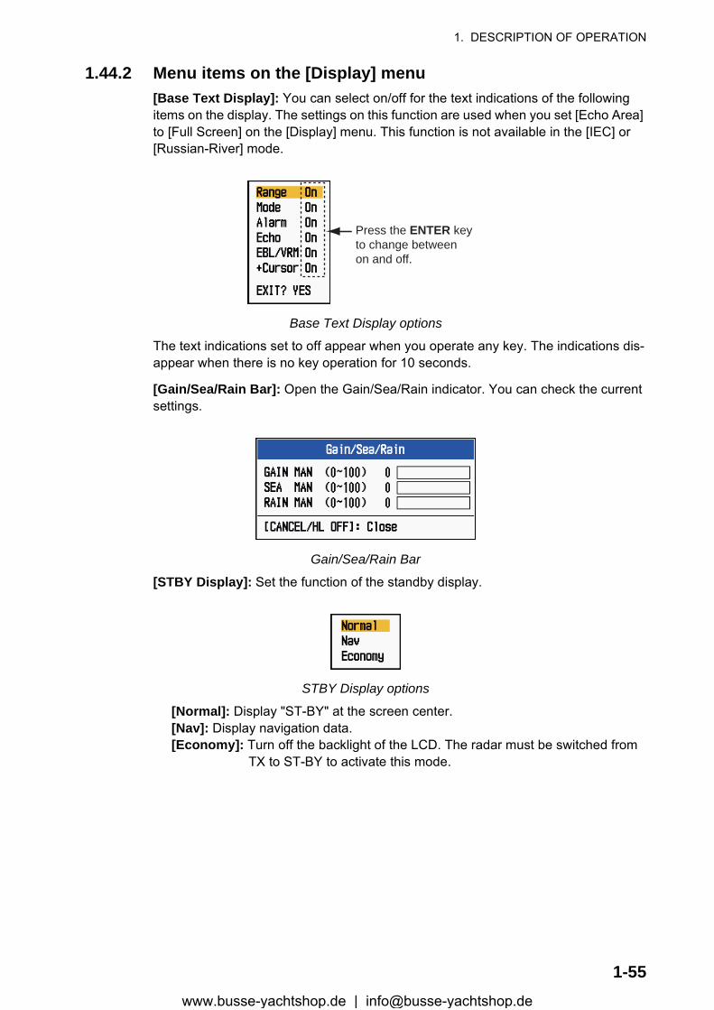
1. DESCRIPTION OF OPERATION
1.44.2 Menu items on the [Display] menu[Base Text Display]: You can select on/off for the text indications of the following items on the display. The settings on this function are used when you set [Echo Area] to [Full Screen] on the [Display] menu. This function is not available in the [IEC] or [Russian-River] mode.
Base Text Display options
The text indications set to off appear when you operate any key. The indications dis-appear when there is no key operation for 10 seconds.
[Gain/Sea/Rain Bar]: Open the Gain/Sea/Rain indicator. You can check the current settings.
Gain/Sea/Rain Bar
[STBY Display]: Set the function of the standby display.
STBY Display options
[Normal]: Display "ST-BY" at the screen center. [Nav]: Display navigation data. [Economy]: Turn off the backlight of the LCD. The radar must be switched from TX to ST-BY to activate this mode.
Press the ENTER keyto change betweenon and off.
1-55www.busse-yachtshop.de | [email protected]
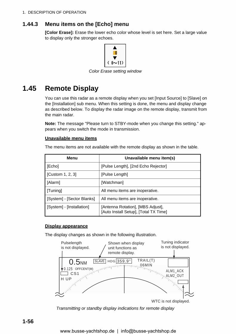
1. DESCRIPTION OF OPERATION
1.44.3 Menu items on the [Echo] menu[Color Erase]: Erase the lower echo color whose level is set here. Set a large value to display only the stronger echoes.
Color Erase setting window
1.45 Remote DisplayYou can use this radar as a remote display when you set [Input Source] to [Slave] on the [Installation] sub menu. When this setting is done, the menu and display change as described below. To display the radar image on the remote display, transmit from the main radar.
Note: The message "Please turn to STBY-mode when you change this setting." ap-pears when you switch the mode in transmission.
Unavailable menu items
The menu items are not available with the remote display as shown in the table.
Display appearance
The display changes as shown in the following illustration.
Transmitting or standby display indications for remote display
Menu Unavailable menu item(s)
[Echo] [Pulse Length], [2nd Echo Rejector]
[Custom 1, 2, 3] [Pulse Length]
[Alarm] [Watchman]
[Tuning] All menu items are inoperative.
[System] - [Sector Blanks] All menu items are inoperative.
[System] - [Installation] [Antenna Rotation], [MBS Adjust],[Auto Install Setup], [Total TX Time]
HDG
OFFCENT(M)
Shown when displayunit functions asremote display.
Tuning indicatoris not displayed.
Pulselength is not displayed.
WTC is not displayed.
SLAVE0.5NM0.125
CS1H UP
TRAIL(T)06MIN
ALM1_ACKALM2_OUT
359.9°
1-56www.busse-yachtshop.de | [email protected]
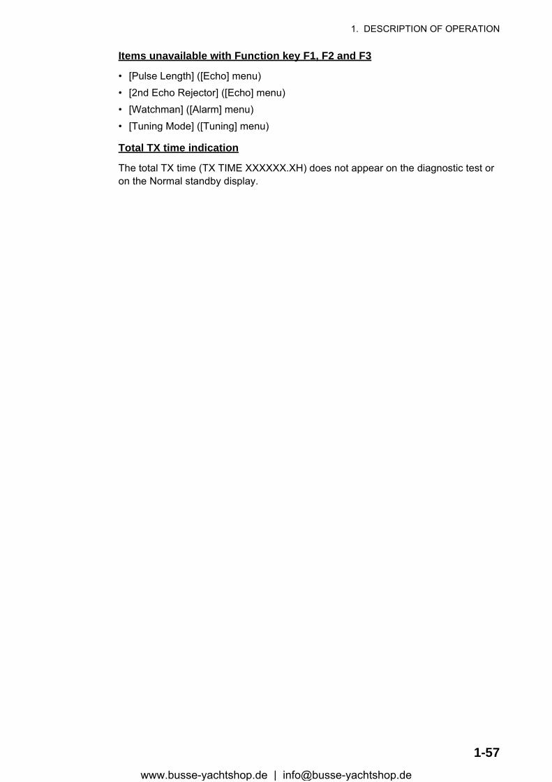
1. DESCRIPTION OF OPERATION
Items unavailable with Function key F1, F2 and F3
• [Pulse Length] ([Echo] menu)• [2nd Echo Rejector] ([Echo] menu)• [Watchman] ([Alarm] menu)• [Tuning Mode] ([Tuning] menu)
Total TX time indication
The total TX time (TX TIME XXXXXX.XH) does not appear on the diagnostic test or on the Normal standby display.
1-57www.busse-yachtshop.de | [email protected]

1. DESCRIPTION OF OPERATION
This page is intentionally left blank.
1-58www.busse-yachtshop.de | [email protected]
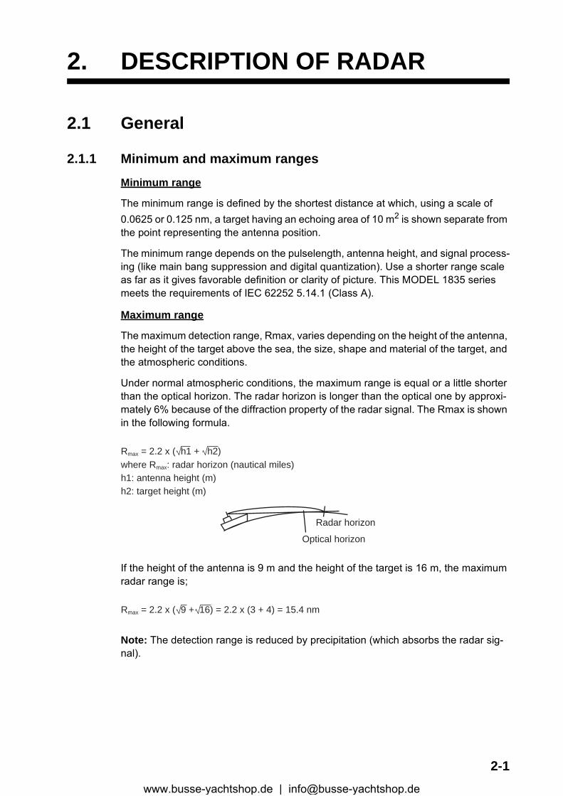
2. DESCRIPTION OF RADAR
2.1 General
2.1.1 Minimum and maximum ranges
Minimum range
The minimum range is defined by the shortest distance at which, using a scale of 0.0625 or 0.125 nm, a target having an echoing area of 10 m2 is shown separate from the point representing the antenna position.
The minimum range depends on the pulselength, antenna height, and signal process-ing (like main bang suppression and digital quantization). Use a shorter range scale as far as it gives favorable definition or clarity of picture. This MODEL 1835 series meets the requirements of IEC 62252 5.14.1 (Class A).
Maximum range
The maximum detection range, Rmax, varies depending on the height of the antenna, the height of the target above the sea, the size, shape and material of the target, and the atmospheric conditions.
Under normal atmospheric conditions, the maximum range is equal or a little shorter than the optical horizon. The radar horizon is longer than the optical one by approxi-mately 6% because of the diffraction property of the radar signal. The Rmax is shown in the following formula.
If the height of the antenna is 9 m and the height of the target is 16 m, the maximum radar range is;
Note: The detection range is reduced by precipitation (which absorbs the radar sig-nal).
Rmax = 2.2 x ( h1 + h2)where Rmax: radar horizon (nautical miles)h1: antenna height (m)h2: target height (m)
Radar horizon
Optical horizon
Rmax = 2.2 x ( 9 + 16) = 2.2 x (3 + 4) = 15.4 nm
2-1www.busse-yachtshop.de | [email protected]
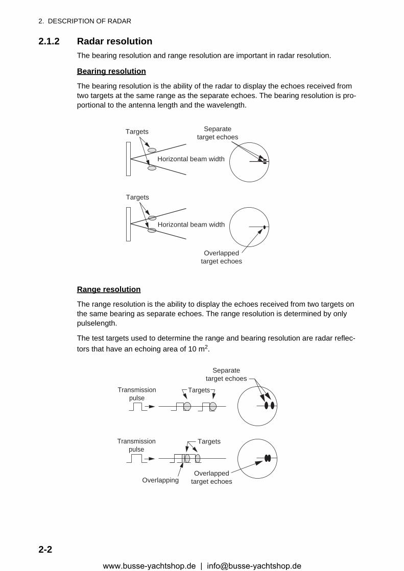
2. DESCRIPTION OF RADAR
2.1.2 Radar resolutionThe bearing resolution and range resolution are important in radar resolution.
Bearing resolution
The bearing resolution is the ability of the radar to display the echoes received from two targets at the same range as the separate echoes. The bearing resolution is pro-portional to the antenna length and the wavelength.
Range resolution
The range resolution is the ability to display the echoes received from two targets on the same bearing as separate echoes. The range resolution is determined by only pulselength.
The test targets used to determine the range and bearing resolution are radar reflec-tors that have an echoing area of 10 m2.
Targets
Targets
Horizontal beam width
Horizontal beam width
Separatetarget echoes
Overlappedtarget echoes
Separatetarget echoes
Overlappedtarget echoes
Targets
Targets
Overlapping
Transmissionpulse
Transmissionpulse
2-2www.busse-yachtshop.de | [email protected]

2. DESCRIPTION OF RADAR
2.1.3 Bearing accuracyOne of the most important features of the radar is how accurately the bearing of a tar-get can be measured. The accuracy of bearing measurement depends on the narrow-ness of the radar beam. The bearing is taken relative to the heading of the ship. Correct adjustment of the heading line at installation is important to get accurate bear-ings. To minimize the error when you measure the bearing of a target, put the target echo at the extreme position on the screen by selecting a suitable range.
2.1.4 Range measurementMeasurement of the range to a target is important function of the radar. There are three methods of measuring range: the fixed range rings, the Variable Range Marker (VRM), and the cursor (if set to measure range and bearing). The fixed range rings appear on the screen with a given interval and provide a rough estimate of the range to a target. The diameter of VRM is increased or decreased so that the marker touches the inner edge of the target (see section 1.15.2). The VRM is a more accurate range measurement than the fixed range rings. For cursor, see section 1.13.
2.2 False EchoesThe echo signals can appear on the screen at positions where there is no target or disappear when there are targets. These false echoes are shown below.
2.2.1 Multiple echoesMultiple echoes occur when a transmitted pulse returns from a solid object like a large ship, bridge, or breakwater. A second, a third or more echoes can be seen on the dis-play at double, triple or other multiples of the actual range of the target as shown be-low. You can reduce and remove the multiple reflection echoes with the A/C SEA control.
Multiple echoes
Your ship
Target
Trueecho
Multipleecho
2-3www.busse-yachtshop.de | [email protected]
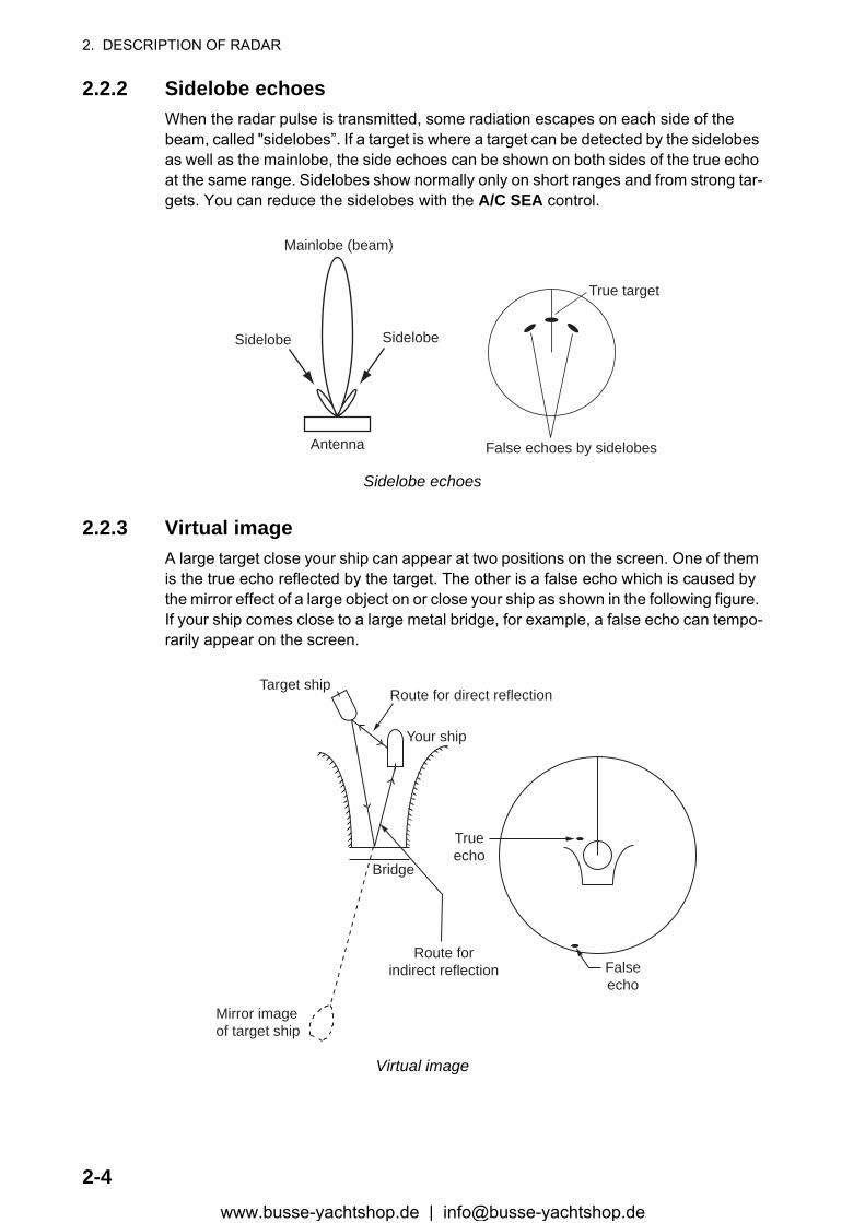
2. DESCRIPTION OF RADAR
2.2.2 Sidelobe echoesWhen the radar pulse is transmitted, some radiation escapes on each side of the beam, called "sidelobes”. If a target is where a target can be detected by the sidelobes as well as the mainlobe, the side echoes can be shown on both sides of the true echo at the same range. Sidelobes show normally only on short ranges and from strong tar-gets. You can reduce the sidelobes with the A/C SEA control.
Sidelobe echoes
2.2.3 Virtual imageA large target close your ship can appear at two positions on the screen. One of them is the true echo reflected by the target. The other is a false echo which is caused by the mirror effect of a large object on or close your ship as shown in the following figure. If your ship comes close to a large metal bridge, for example, a false echo can tempo-rarily appear on the screen.
Virtual image
True target
Mainlobe (beam)
Antenna
Sidelobe
False echoes by sidelobes
Sidelobe
Trueecho
Falseecho
Your ship
Target ship
Mirror imageof target ship
Bridge
Route for direct reflection
Route forindirect reflection
2-4www.busse-yachtshop.de | [email protected]
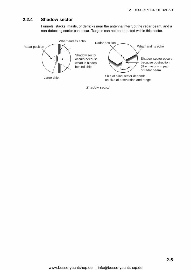
2. DESCRIPTION OF RADAR
2.2.4 Shadow sectorFunnels, stacks, masts, or derricks near the antenna interrupt the radar beam, and a non-detecting sector can occur. Targets can not be detected within this sector.
Shadow sector
Wharf and its echo
Large ship
Shadow sectoroccurs becausewharf is hiddenbehind ship.
Size of blind sector dependson size of obstruction and range.
Radar positionRadar position
Wharf and its echo
Shadow sector occursbecause obstruction(like mast) is in pathof radar beam.
2-5www.busse-yachtshop.de | [email protected]
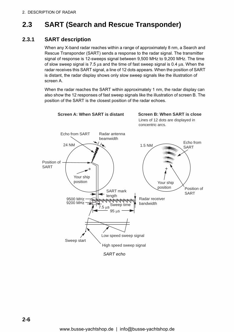
2. DESCRIPTION OF RADAR
2.3 SART (Search and Rescue Transponder)
2.3.1 SART descriptionWhen any X-band radar reaches within a range of approximately 8 nm, a Search and Rescue Transponder (SART) sends a response to the radar signal. The transmitter signal of response is 12-sweeps signal between 9,500 MHz to 9,200 MHz. The time of slow sweep signal is 7.5 μs and the time of fast sweep signal is 0.4 μs. When the radar receives this SART signal, a line of 12 dots appears. When the position of SART is distant, the radar display shows only slow sweep signals like the illustration of screen A.
When the radar reaches the SART within approximately 1 nm, the radar display can also show the 12 responses of fast sweep signals like the illustration of screen B. The position of the SART is the closest position of the radar echoes.
SART echo
9500 MHz9200 MHz
Radar antennabeamwidth
Screen A: When SART is distant Screen B: When SART is close
Echo from SART
Position ofSART
Your shipposition Your ship
positionSART marklength
Radar receiverbandwidthSweep time7.5 µs
95 µs
Sweep startHigh speed sweep signal
Low speed sweep signal
24 NM 1.5 NM
Position ofSART
Echo fromSART
Lines of 12 dots are displayed inconcentric arcs.
2-6www.busse-yachtshop.de | [email protected]
2. DESCRIPTION OF RADAR
2.3.2 General remarks on receiving SART
SART range errors
When the SART is at a range greater than approximately 1 nm, the first dot is dis-played at 0.64 nm beyond the true position of the SART. When the range closes so that the fast sweep responses are seen also, the first range echoes are displayed at 150 m beyond the true position.
Range scale
When you find the SART position, do as follows:
1. Use the RANGE key to set the range scale to 6 nm or 12 nm.2. Turn off [A/C Auto].3. Turn off [Int Rejector].
SART display
To display only the SART echo clearly on the radar screen, reduce the tuning on man-ual mode. The normal radar echoes get weak, however, the SART echoes remain. Your ship comes close to the SART, the arc for the SART display becomes larger. Most of the radar screen becomes fuzzy. Adjust the A/C SEA and GAIN controls to display the necessary screen.
2-7www.busse-yachtshop.de | [email protected]
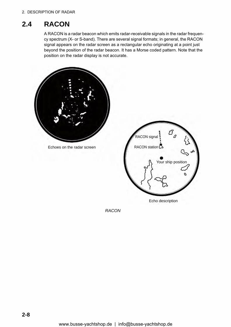
2. DESCRIPTION OF RADAR
2.4 RACONA RACON is a radar beacon which emits radar-receivable signals in the radar frequen-cy spectrum (X- or S-band). There are several signal formats; in general, the RACON signal appears on the radar screen as a rectangular echo originating at a point just beyond the position of the radar beacon. It has a Morse coded pattern. Note that the position on the radar display is not accurate.
RACON
Echoes on the radar screen
Echo description
Your ship position
RACON signal
RACON station
2-8www.busse-yachtshop.de | [email protected]

3. ARPA OPERATION
The Automatic Radar Plotter ARP-11 (option) manually or automatically acquires and tracks ten targets. Once a target is acquired automatically or manually, a target is au-tomatically tracked within 0.1 to 16 nm.
3.1 Precautions for Use
3.2 Controls for Use with ARPAENTER: Acquire cursor-selected target. Display data for tracked target (in the data box at the bottom of the screen).
CANCEL/HL OFF: Remove data of cursor-selected tracked target from the data box. Stop tracking the cursor-selected target (when its data is not displayed in the data box).
MENU: Access the [Target] and [ARPA] menus for ARPA operations.
Cursorpad: Select a target to acquire (or cancel the tracking). Select a target to show (or remove) target data.
Do not depend on one navigation devicefor the navigation of the ship. Thenavigator must check all aids availableto confirm position. Electronic aids arenot a replacement for basic navigationprinciples and common sense.
· The ARPA automatically tracks an automatically or manually acquired radar target and calculates its course and speed, indicating them by a vector. Since the data from the auto plotter depend on the selected radar targets, the radar must be optimally tuned for use with the auto plotter, to ensure required targets will not be lost or unnecessary targets like sea returns and noise will not be acquired and tracked.
· A target is not always a landmass, reef, ship, but can be returns from the sea surface and clutter. As the level of clutter changes with the environment, the operator must correctly adjust the A/C SEA, A/C RAIN and GAIN controls so that the target echoes do not disappear from the radar screen.
The plotting accuracy and response ofthis ARPA meets IMO standards.The tracking accuracy is affected by thefollowing:
· The tracking accuracy is affected by course change. One to two minutes is required to restore vectors to full accuracy after a sudden course change. (The actual amount depends on gyrocompass specifications.)· The amount of tracking delay is inversely proportional to the relative speed of the target. Delay is on the order of 15-30 seconds for high relative speed; 30-60 seconds for low relative speed.
The display accuracy is affected by thefollowing:
· Echo intensity· Pulse width of radar transmission· Radar bearing error· Gyrocompass error· Course change (your ship or target)
CAUTIONCAUTION CAUTIONCAUTION
3-1www.busse-yachtshop.de | [email protected]
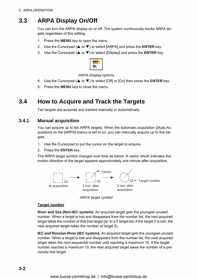
3. ARPA OPERATION
3.3 ARPA Display On/OffYou can turn the ARPA display on or off. The system continuously tracks ARPA tar-gets regardless of this setting.
1. Press the MENU key to open the menu.2. Use the Cursorpad ( or ) to select [ARPA] and press the ENTER key.3. Use the Cursorpad ( or ) to select [Display] and press the ENTER key.
ARPA-Display options4. Use the Cursorpad ( or ) to select [Off] or [On] then press the ENTER key.5. Press the MENU key to close the menu.
3.4 How to Acquire and Track the TargetsTen targets are acquired and tracked manually or automatically.
3.4.1 Manual acquisitionYou can acquire up to ten ARPA targets. When the automatic acquisition ([Auto Ac-quisition] on the [ARPA] menu) is set to on, you can manually acquire up to five tar-gets.
1. Use the Cursorpad to put the cursor on the target to acquire.2. Press the ENTER key.The ARPA target symbol changes over time as below. A vector which indicates the motion direction of the target appears approximately one minute after acquisition.
ARPA target symbol
Target number
River and Sea (Non-IEC system): An acquired target gets the youngest unused number. When a target is lost and disappears from the number list, the next acquired target takes the number of that lost target (ie; In a 5 target list, if the target 2 is lost, the next acquired target takes the number of target 2).
IEC and Russian-River (IEC system): An acquired target gets the youngest unused number. When a target is lost and disappears from the number list, the next acquired target takes the next sequential number until reaching a maximum 10. If the target number reaches a maximum 10, the next acquired target takes the number of a pre-viously lost target.
At acquisition 1 min. afteracquisition
3 min. afteracquisition
01 Target number
Vector
0101
3-2www.busse-yachtshop.de | [email protected]
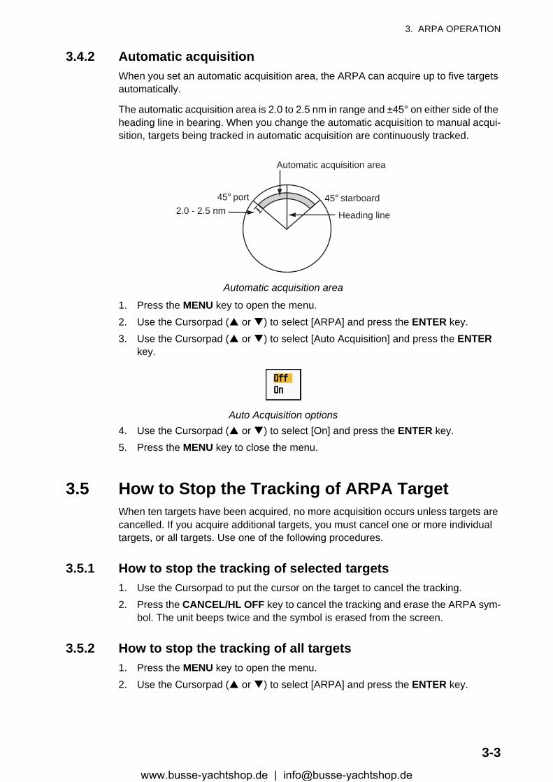
3. ARPA OPERATION
3.4.2 Automatic acquisitionWhen you set an automatic acquisition area, the ARPA can acquire up to five targets automatically.
The automatic acquisition area is 2.0 to 2.5 nm in range and ±45° on either side of the heading line in bearing. When you change the automatic acquisition to manual acqui-sition, targets being tracked in automatic acquisition are continuously tracked.
Automatic acquisition area
1. Press the MENU key to open the menu.2. Use the Cursorpad ( or ) to select [ARPA] and press the ENTER key.3. Use the Cursorpad ( or ) to select [Auto Acquisition] and press the ENTER
key.
Auto Acquisition options4. Use the Cursorpad ( or ) to select [On] and press the ENTER key.5. Press the MENU key to close the menu.
3.5 How to Stop the Tracking of ARPA TargetWhen ten targets have been acquired, no more acquisition occurs unless targets are cancelled. If you acquire additional targets, you must cancel one or more individual targets, or all targets. Use one of the following procedures.
3.5.1 How to stop the tracking of selected targets1. Use the Cursorpad to put the cursor on the target to cancel the tracking.2. Press the CANCEL/HL OFF key to cancel the tracking and erase the ARPA sym-
bol. The unit beeps twice and the symbol is erased from the screen.
3.5.2 How to stop the tracking of all targets1. Press the MENU key to open the menu.2. Use the Cursorpad ( or ) to select [ARPA] and press the ENTER key.
Automatic acquisition area
45° port 45° starboard2.0 - 2.5 nm Heading line
3-3www.busse-yachtshop.de | [email protected]

3. ARPA OPERATION
3. Use the Cursorpad ( or ) to select [All Cancel] and press the ENTER key.
All Cancel options4. Use the Cursorpad ( ) to select [Yes] and press the ENTER key. All symbols are
erased from the screen and the long beep sounds.5. Press the MENU key to close the menu.
3.6 Vector Attributes
3.6.1 What is a vector?A vector is a line extending from a tracked target. A vector shows speed and course of the target. The top of a vector shows estimated position of the target after the se-lected vector time elapses. If you extend the vector length (time), you can evaluate the risk of collision with any target.
When vector time is 15 minutes
3.6.2 Vector time and vector reference1. Press the MENU key to open the menu.2. Use the Cursorpad ( or ) to select [Target] and press the ENTER key.
Target menu
Vector
Current position of the target
Vector timeVector timeVector timePredicted position of the target in 15 minutes later
3-4www.busse-yachtshop.de | [email protected]
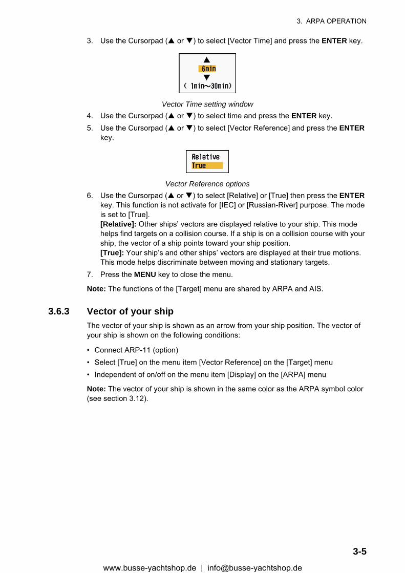
3. ARPA OPERATION
3. Use the Cursorpad ( or ) to select [Vector Time] and press the ENTER key.
Vector Time setting window4. Use the Cursorpad ( or ) to select time and press the ENTER key.5. Use the Cursorpad ( or ) to select [Vector Reference] and press the ENTER
key.
Vector Reference options6. Use the Cursorpad ( or ) to select [Relative] or [True] then press the ENTER
key. This function is not activate for [IEC] or [Russian-River] purpose. The mode is set to [True].[Relative]: Other ships’ vectors are displayed relative to your ship. This mode helps find targets on a collision course. If a ship is on a collision course with your ship, the vector of a ship points toward your ship position.[True]: Your ship’s and other ships’ vectors are displayed at their true motions. This mode helps discriminate between moving and stationary targets.
7. Press the MENU key to close the menu.
Note: The functions of the [Target] menu are shared by ARPA and AIS.
3.6.3 Vector of your shipThe vector of your ship is shown as an arrow from your ship position. The vector of your ship is shown on the following conditions:
• Connect ARP-11 (option)• Select [True] on the menu item [Vector Reference] on the [Target] menu• Independent of on/off on the menu item [Display] on the [ARPA] menu
Note: The vector of your ship is shown in the same color as the ARPA symbol color (see section 3.12).
3-5www.busse-yachtshop.de | [email protected]
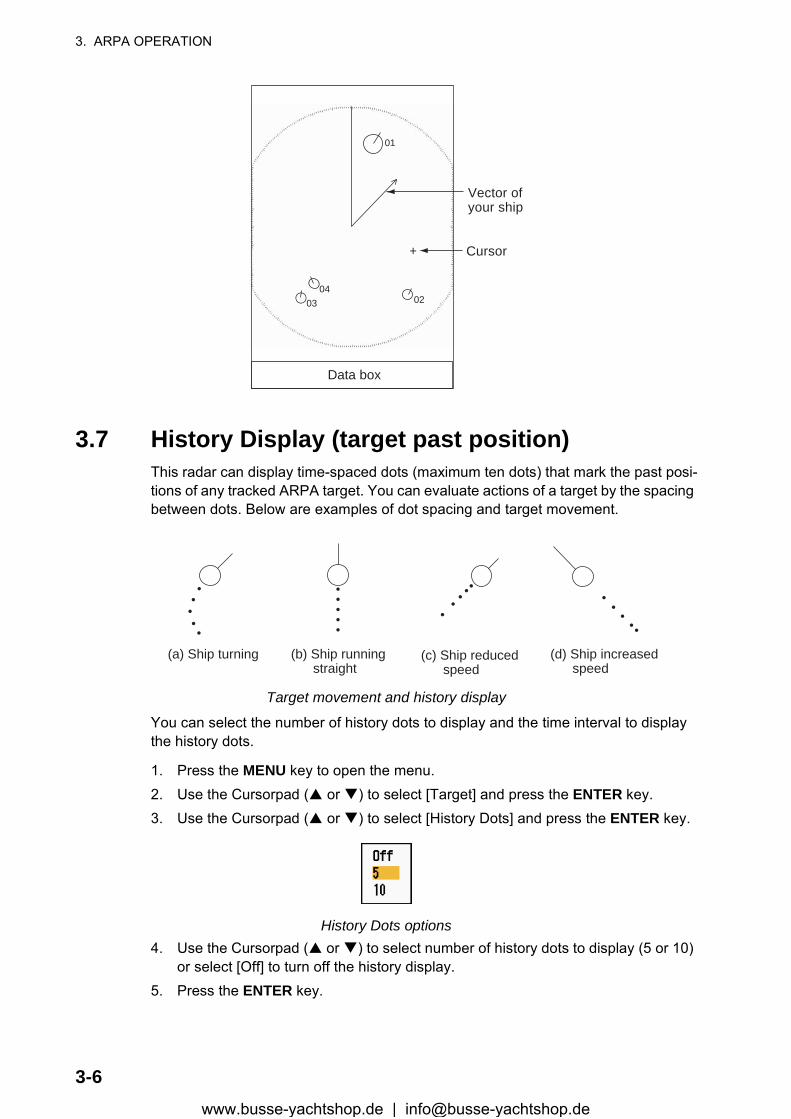
3. ARPA OPERATION
3.7 History Display (target past position)This radar can display time-spaced dots (maximum ten dots) that mark the past posi-tions of any tracked ARPA target. You can evaluate actions of a target by the spacing between dots. Below are examples of dot spacing and target movement.
Target movement and history display
You can select the number of history dots to display and the time interval to display the history dots.
1. Press the MENU key to open the menu.2. Use the Cursorpad ( or ) to select [Target] and press the ENTER key.3. Use the Cursorpad ( or ) to select [History Dots] and press the ENTER key.
History Dots options4. Use the Cursorpad ( or ) to select number of history dots to display (5 or 10)
or select [Off] to turn off the history display.5. Press the ENTER key.
+
Vector ofyour ship
01
Data box
02
Cursor
0304
(a) Ship turning (b) Ship running straight
(c) Ship reduced speed
(d) Ship increased speed
3-6www.busse-yachtshop.de | [email protected]
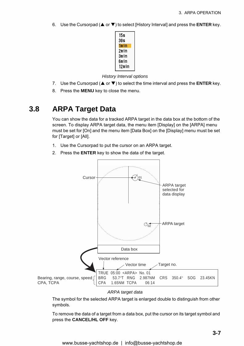
3. ARPA OPERATION
6. Use the Cursorpad ( or ) to select [History Interval] and press the ENTER key.
History Interval options7. Use the Cursorpad ( or ) to select the time interval and press the ENTER key.8. Press the MENU key to close the menu.
3.8 ARPA Target DataYou can show the data for a tracked ARPA target in the data box at the bottom of the screen. To display ARPA target data, the menu item [Display] on the [ARPA] menu must be set for [On] and the menu item [Data Box] on the [Display] menu must be set for [Target] or [All].
1. Use the Cursorpad to put the cursor on an ARPA target.2. Press the ENTER key to show the data of the target.
ARPA target dataThe symbol for the selected ARPA target is enlarged double to distinguish from other symbols.
To remove the data of a target from a data box, put the cursor on its target symbol and press the CANCEL/HL OFF key.
TRUE 05:00 <ARPA> No. 01BRG 53.7°T RNG 2.987NM CRS 350.4° SOG 23.45KNCPA 1.65NM TCPA 06:14
Vector referenceVector time Target no.
Bearing, range, course, speed CPA, TCPA
+
ARPA targetselected fordata display
01
ARPA target
Data box
02
Cursor
3-7www.busse-yachtshop.de | [email protected]
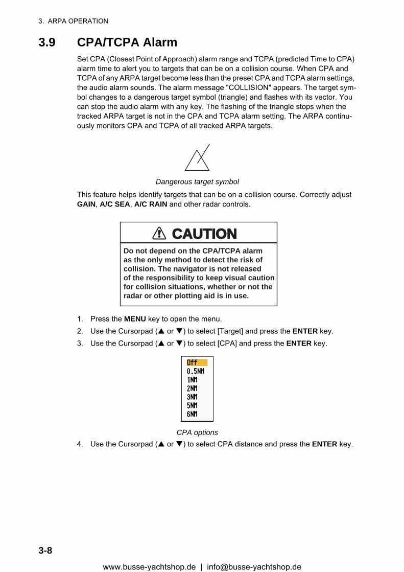
3. ARPA OPERATION
3.9 CPA/TCPA AlarmSet CPA (Closest Point of Approach) alarm range and TCPA (predicted Time to CPA) alarm time to alert you to targets that can be on a collision course. When CPA and TCPA of any ARPA target become less than the preset CPA and TCPA alarm settings, the audio alarm sounds. The alarm message "COLLISION" appears. The target sym-bol changes to a dangerous target symbol (triangle) and flashes with its vector. You can stop the audio alarm with any key. The flashing of the triangle stops when the tracked ARPA target is not in the CPA and TCPA alarm setting. The ARPA continu-ously monitors CPA and TCPA of all tracked ARPA targets.
Dangerous target symbol
This feature helps identify targets that can be on a collision course. Correctly adjust GAIN, A/C SEA, A/C RAIN and other radar controls.
1. Press the MENU key to open the menu.2. Use the Cursorpad ( or ) to select [Target] and press the ENTER key.3. Use the Cursorpad ( or ) to select [CPA] and press the ENTER key.
CPA options4. Use the Cursorpad ( or ) to select CPA distance and press the ENTER key.
CAUTIONCAUTIONDo not depend on the CPA/TCPA alarmas the only method to detect the risk ofcollision. The navigator is not releasedof the responsibility to keep visual cautionfor collision situations, whether or not theradar or other plotting aid is in use.
3-8www.busse-yachtshop.de | [email protected]
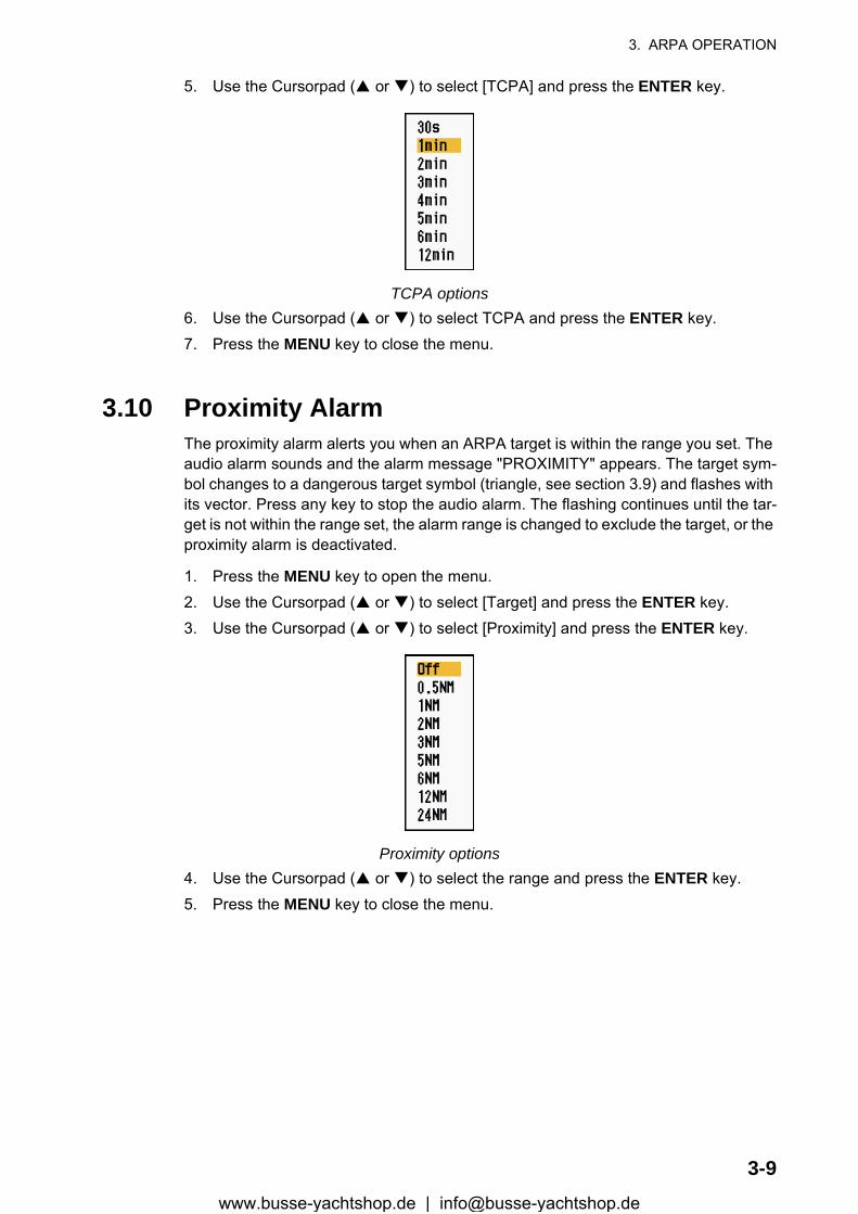
3. ARPA OPERATION
5. Use the Cursorpad ( or ) to select [TCPA] and press the ENTER key.
TCPA options6. Use the Cursorpad ( or ) to select TCPA and press the ENTER key.7. Press the MENU key to close the menu.
3.10 Proximity AlarmThe proximity alarm alerts you when an ARPA target is within the range you set. The audio alarm sounds and the alarm message "PROXIMITY" appears. The target sym-bol changes to a dangerous target symbol (triangle, see section 3.9) and flashes with its vector. Press any key to stop the audio alarm. The flashing continues until the tar-get is not within the range set, the alarm range is changed to exclude the target, or the proximity alarm is deactivated.
1. Press the MENU key to open the menu.2. Use the Cursorpad ( or ) to select [Target] and press the ENTER key.3. Use the Cursorpad ( or ) to select [Proximity] and press the ENTER key.
Proximity options4. Use the Cursorpad ( or ) to select the range and press the ENTER key.5. Press the MENU key to close the menu.
3-9www.busse-yachtshop.de | [email protected]
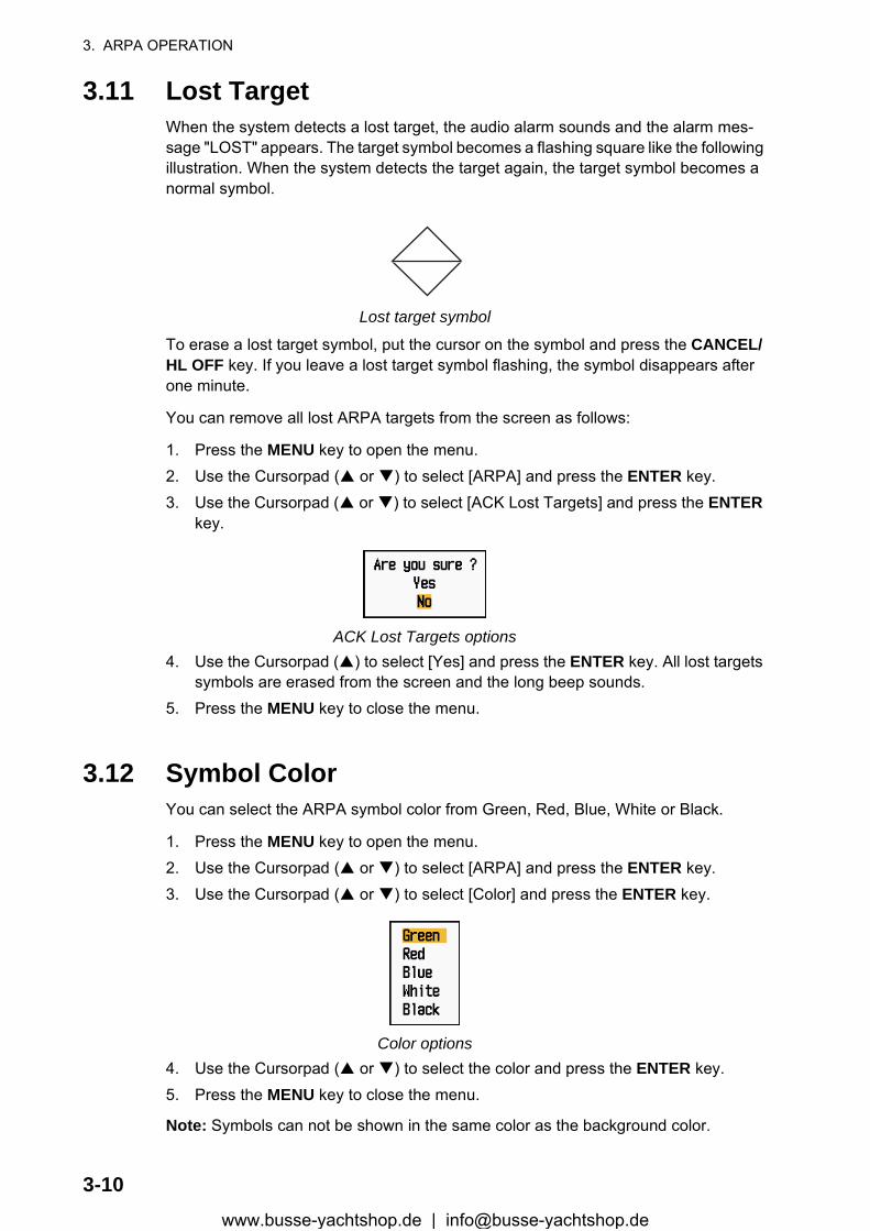
3. ARPA OPERATION
3.11 Lost TargetWhen the system detects a lost target, the audio alarm sounds and the alarm mes-sage "LOST" appears. The target symbol becomes a flashing square like the following illustration. When the system detects the target again, the target symbol becomes a normal symbol.
Lost target symbol
To erase a lost target symbol, put the cursor on the symbol and press the CANCEL/HL OFF key. If you leave a lost target symbol flashing, the symbol disappears after one minute.
You can remove all lost ARPA targets from the screen as follows:
1. Press the MENU key to open the menu.2. Use the Cursorpad ( or ) to select [ARPA] and press the ENTER key.3. Use the Cursorpad ( or ) to select [ACK Lost Targets] and press the ENTER
key.
ACK Lost Targets options4. Use the Cursorpad ( ) to select [Yes] and press the ENTER key. All lost targets
symbols are erased from the screen and the long beep sounds.5. Press the MENU key to close the menu.
3.12 Symbol ColorYou can select the ARPA symbol color from Green, Red, Blue, White or Black.
1. Press the MENU key to open the menu.2. Use the Cursorpad ( or ) to select [ARPA] and press the ENTER key.3. Use the Cursorpad ( or ) to select [Color] and press the ENTER key.
Color options4. Use the Cursorpad ( or ) to select the color and press the ENTER key.5. Press the MENU key to close the menu.
Note: Symbols can not be shown in the same color as the background color.
3-10www.busse-yachtshop.de | [email protected]
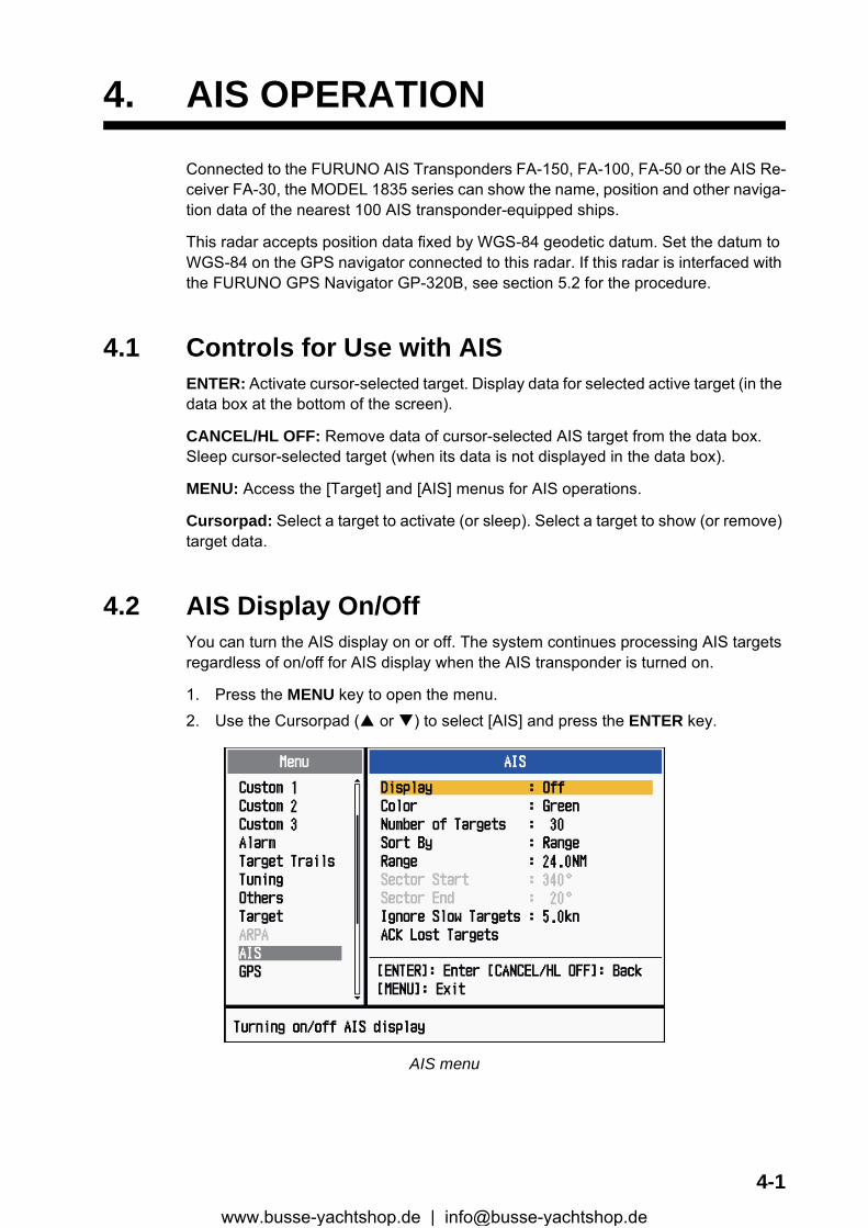
4. AIS OPERATION
Connected to the FURUNO AIS Transponders FA-150, FA-100, FA-50 or the AIS Re-ceiver FA-30, the MODEL 1835 series can show the name, position and other naviga-tion data of the nearest 100 AIS transponder-equipped ships.
This radar accepts position data fixed by WGS-84 geodetic datum. Set the datum to WGS-84 on the GPS navigator connected to this radar. If this radar is interfaced with the FURUNO GPS Navigator GP-320B, see section 5.2 for the procedure.
4.1 Controls for Use with AISENTER: Activate cursor-selected target. Display data for selected active target (in the data box at the bottom of the screen).
CANCEL/HL OFF: Remove data of cursor-selected AIS target from the data box. Sleep cursor-selected target (when its data is not displayed in the data box).
MENU: Access the [Target] and [AIS] menus for AIS operations.
Cursorpad: Select a target to activate (or sleep). Select a target to show (or remove) target data.
4.2 AIS Display On/OffYou can turn the AIS display on or off. The system continues processing AIS targets regardless of on/off for AIS display when the AIS transponder is turned on.
1. Press the MENU key to open the menu.2. Use the Cursorpad ( or ) to select [AIS] and press the ENTER key.
AIS menu
4-1www.busse-yachtshop.de | [email protected]

4. AIS OPERATION
3. Use the Cursorpad ( or ) to select [Display] and press the ENTER key.
AIS-Display options4. Use the Cursorpad ( or ) to select [Off] or [On] then press the ENTER key.5. Press the MENU key to close the menu.
4.3 AIS SymbolsWhen the AIS is turned on, AIS targets are displayed with AIS symbol as below.
AIS symbols
Note: The AIS symbols are momentarily erased after the screen is redrawn when the heading is changed on the head-up mode.
4.4 Activating, Sleeping TargetsWhen you change a sleeping target to an activated target, a vector shows the course and speed of that target. You can easily judge the target movement by the vector.
Activated target
Sleepingtarget
Activatedtarget
Dangerous target
Lost target Target selectedfor data display
Heading line
SOG (Speed Over Ground) andCOG (Course over Ground) vector
(If there is no heading data,the line points in direction of COG.)
ROT(Rate of Turn)
4-2www.busse-yachtshop.de | [email protected]
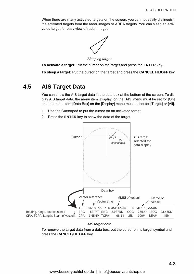
4. AIS OPERATION
When there are many activated targets on the screen, you can not easily distinguish the activated targets from the radar images or ARPA targets. You can sleep an acti-vated target for easy view of radar images.
Sleeping target
To activate a target: Put the cursor on the target and press the ENTER key.
To sleep a target: Put the cursor on the target and press the CANCEL HL/OFF key.
4.5 AIS Target DataYou can show the AIS target data in the data box at the bottom of the screen. To dis-play AIS target data, the menu item [Display] on the [AIS] menu must be set for [On] and the menu item [Data Box] on the [Display] menu must be set for [Target] or [All].
1. Use the Cursorpad to put the cursor on an activated target.2. Press the ENTER key to show the data of the target.
AIS target dataTo remove the target data from a data box, put the cursor on its target symbol and press the CANCEL/HL OFF key.
AIS targetselected fordata display
MMSI of vessel Name ofvessel
(A)000000026
Cursor
Data box
TRUE 05:00 <AIS> MMSI: 12345 NAME: PEGASUSBRG 53.7°T RNG 2.987NM COG 350.4° SOG 23.45KNCPA 1.65NM TCPA 06:14 LEN 100M BEAM 45M
Vector referenceVector time
Bearing, range, course, speed CPA, TCPA, Length, Beam of vessel
+
4-3www.busse-yachtshop.de | [email protected]
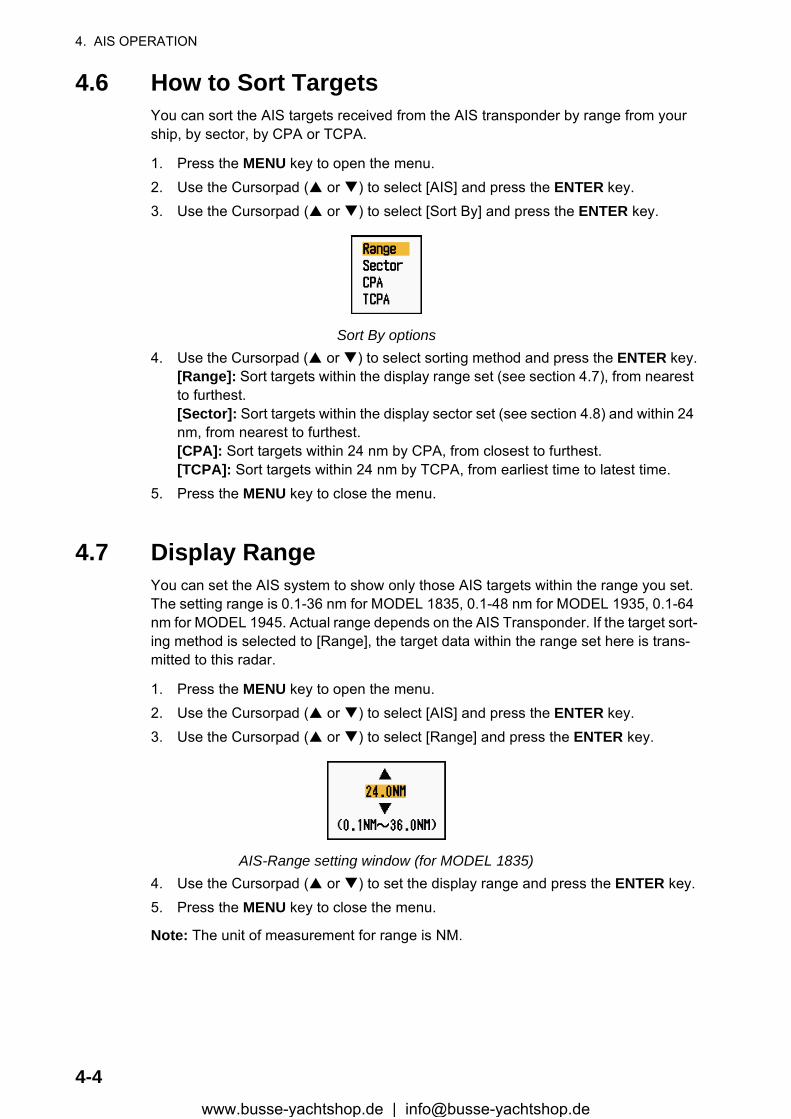
4. AIS OPERATION
4.6 How to Sort TargetsYou can sort the AIS targets received from the AIS transponder by range from your ship, by sector, by CPA or TCPA.
1. Press the MENU key to open the menu.2. Use the Cursorpad ( or ) to select [AIS] and press the ENTER key.3. Use the Cursorpad ( or ) to select [Sort By] and press the ENTER key.
Sort By options4. Use the Cursorpad ( or ) to select sorting method and press the ENTER key.
[Range]: Sort targets within the display range set (see section 4.7), from nearest to furthest.[Sector]: Sort targets within the display sector set (see section 4.8) and within 24 nm, from nearest to furthest.[CPA]: Sort targets within 24 nm by CPA, from closest to furthest.[TCPA]: Sort targets within 24 nm by TCPA, from earliest time to latest time.
5. Press the MENU key to close the menu.
4.7 Display RangeYou can set the AIS system to show only those AIS targets within the range you set. The setting range is 0.1-36 nm for MODEL 1835, 0.1-48 nm for MODEL 1935, 0.1-64 nm for MODEL 1945. Actual range depends on the AIS Transponder. If the target sort-ing method is selected to [Range], the target data within the range set here is trans-mitted to this radar.
1. Press the MENU key to open the menu.2. Use the Cursorpad ( or ) to select [AIS] and press the ENTER key.3. Use the Cursorpad ( or ) to select [Range] and press the ENTER key.
AIS-Range setting window (for MODEL 1835)4. Use the Cursorpad ( or ) to set the display range and press the ENTER key.5. Press the MENU key to close the menu.
Note: The unit of measurement for range is NM.
4-4www.busse-yachtshop.de | [email protected]

4. AIS OPERATION
4.8 How to Display the Targets within a Specific Sec-torYou can display AIS targets only within a specific sector. If the target sorting method is selected to [Sector], the target data within the sector set here is transmitted to this radar.
1. Press the MENU key to open the menu.2. Use the Cursorpad ( or ) to select [AIS] and press the ENTER key.3. Use the Cursorpad ( or ) to select [Sector Start] and press the ENTER key.
Sector Start setting window4. Use the Cursorpad ( or ) to set the start point for the sector and press the EN-
TER key.5. Use the Cursorpad ( or ) to select [Sector End] and press the ENTER key.
Sector End setting window6. Use the Cursorpad ( or ) to set the end point for the sector and press the EN-
TER key.7. Press the MENU key to close the menu.
4.9 Number of Targets to DisplayYou can select the maximum number of AIS targets to display. The setting value is 10 to 100. When the screen becomes cluttered with AIS targets, you can limit the number of AIS targets to show. Targets are selected and displayed according to sort method. (See section 4.6.)
1. Press the MENU key to open the menu.2. Use the Cursorpad ( or ) to select [AIS] and press the ENTER key.3. Use the Cursorpad ( or ) to select [Number of Targets] and press the ENTER
key.
Number of Targets setting window
4-5www.busse-yachtshop.de | [email protected]
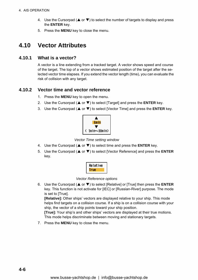
4. AIS OPERATION
4. Use the Cursorpad ( or ) to select the number of targets to display and press the ENTER key.
5. Press the MENU key to close the menu.
4.10 Vector Attributes
4.10.1 What is a vector?A vector is a line extending from a tracked target. A vector shows speed and course of the target. The top of a vector shows estimated position of the target after the se-lected vector time elapses. If you extend the vector length (time), you can evaluate the risk of collision with any target.
4.10.2 Vector time and vector reference1. Press the MENU key to open the menu.2. Use the Cursorpad ( or ) to select [Target] and press the ENTER key.3. Use the Cursorpad ( or ) to select [Vector Time] and press the ENTER key.
Vector Time setting window4. Use the Cursorpad ( or ) to select time and press the ENTER key.5. Use the Cursorpad ( or ) to select [Vector Reference] and press the ENTER
key.
Vector Reference options6. Use the Cursorpad ( or ) to select [Relative] or [True] then press the ENTER
key. This function is not activate for [IEC] or [Russian-River] purpose. The mode is set to [True].[Relative]: Other ships’ vectors are displayed relative to your ship. This mode helps find targets on a collision course. If a ship is on a collision course with your ship, the vector of a ship points toward your ship position.[True]: Your ship’s and other ships’ vectors are displayed at their true motions. This mode helps discriminate between moving and stationary targets.
7. Press the MENU key to close the menu.
4-6www.busse-yachtshop.de | [email protected]
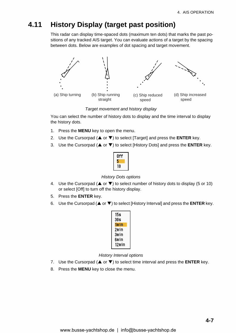
4. AIS OPERATION
4.11 History Display (target past position)This radar can display time-spaced dots (maximum ten dots) that marks the past po-sitions of any tracked AIS target. You can evaluate actions of a target by the spacing between dots. Below are examples of dot spacing and target movement.
Target movement and history display
You can select the number of history dots to display and the time interval to display the history dots.
1. Press the MENU key to open the menu.2. Use the Cursorpad ( or ) to select [Target] and press the ENTER key.3. Use the Cursorpad ( or ) to select [History Dots] and press the ENTER key.
History Dots options4. Use the Cursorpad ( or ) to select number of history dots to display (5 or 10)
or select [Off] to turn off the history display.5. Press the ENTER key.6. Use the Cursorpad ( or ) to select [History Interval] and press the ENTER key.
History Interval options7. Use the Cursorpad ( or ) to select time interval and press the ENTER key.8. Press the MENU key to close the menu.
(a) Ship turning (b) Ship running straight
(c) Ship reduced speed
(d) Ship increased speed
4-7www.busse-yachtshop.de | [email protected]
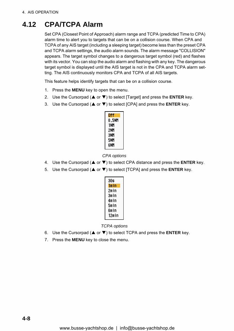
4. AIS OPERATION
4.12 CPA/TCPA AlarmSet CPA (Closest Point of Approach) alarm range and TCPA (predicted Time to CPA) alarm time to alert you to targets that can be on a collision course. When CPA and TCPA of any AIS target (including a sleeping target) become less than the preset CPA and TCPA alarm settings, the audio alarm sounds. The alarm message "COLLISION" appears. The target symbol changes to a dangerous target symbol (red) and flashes with its vector. You can stop the audio alarm and flashing with any key. The dangerous target symbol is displayed until the AIS target is not in the CPA and TCPA alarm set-ting. The AIS continuously monitors CPA and TCPA of all AIS targets.
This feature helps identify targets that can be on a collision course.
1. Press the MENU key to open the menu.2. Use the Cursorpad ( or ) to select [Target] and press the ENTER key.3. Use the Cursorpad ( or ) to select [CPA] and press the ENTER key.
CPA options4. Use the Cursorpad ( or ) to select CPA distance and press the ENTER key.5. Use the Cursorpad ( or ) to select [TCPA] and press the ENTER key.
TCPA options6. Use the Cursorpad ( or ) to select TCPA and press the ENTER key.7. Press the MENU key to close the menu.
4-8www.busse-yachtshop.de | [email protected]

4. AIS OPERATION
4.13 Proximity AlarmThe proximity alarm alerts you when an AIS target is within the range you set. The au-dio alarm sounds and the alarm message "PROXIMITY" appears. The target symbol changes to a dangerous target symbol (red) and flashes with its vector. Press any key to stop the audio alarm and flashing. The dangerous target symbol is displayed until the target is not within the range set, the alarm range is changed to exclude the target, or the proximity alarm is deactivated.
1. Press the MENU key to open the menu.2. Use the Cursorpad ( or ) to select [Target] and press the ENTER key.3. Use the Cursorpad ( or ) to select [Proximity] and press the ENTER key.
Proximity options4. Use the Cursorpad ( or ) to select the range and press the ENTER key.5. Press the MENU key to close the menu.
4.14 Lost TargetWhen AIS data is not received from a target at fixed interval (3-5* report intervals), the target symbol changes to the lost target symbol (flashing). No audio or visual alarm is given for a lost target.
Lost target symbol
* The interval at which AIS data is sent depends on speed of the AIS transponder. For detailed information, refer to the Operator's Manual for the AIS transponder.
You can remove all lost AIS targets from the display as follows:
1. Press the MENU key to open the menu.2. Use the Cursorpad ( or ) to select [AIS] and press the ENTER key.3. Use the Cursorpad ( or ) to select [ACK Lost Targets] and press the ENTER
key.
ACK Lost Targets options
4-9www.busse-yachtshop.de | [email protected]
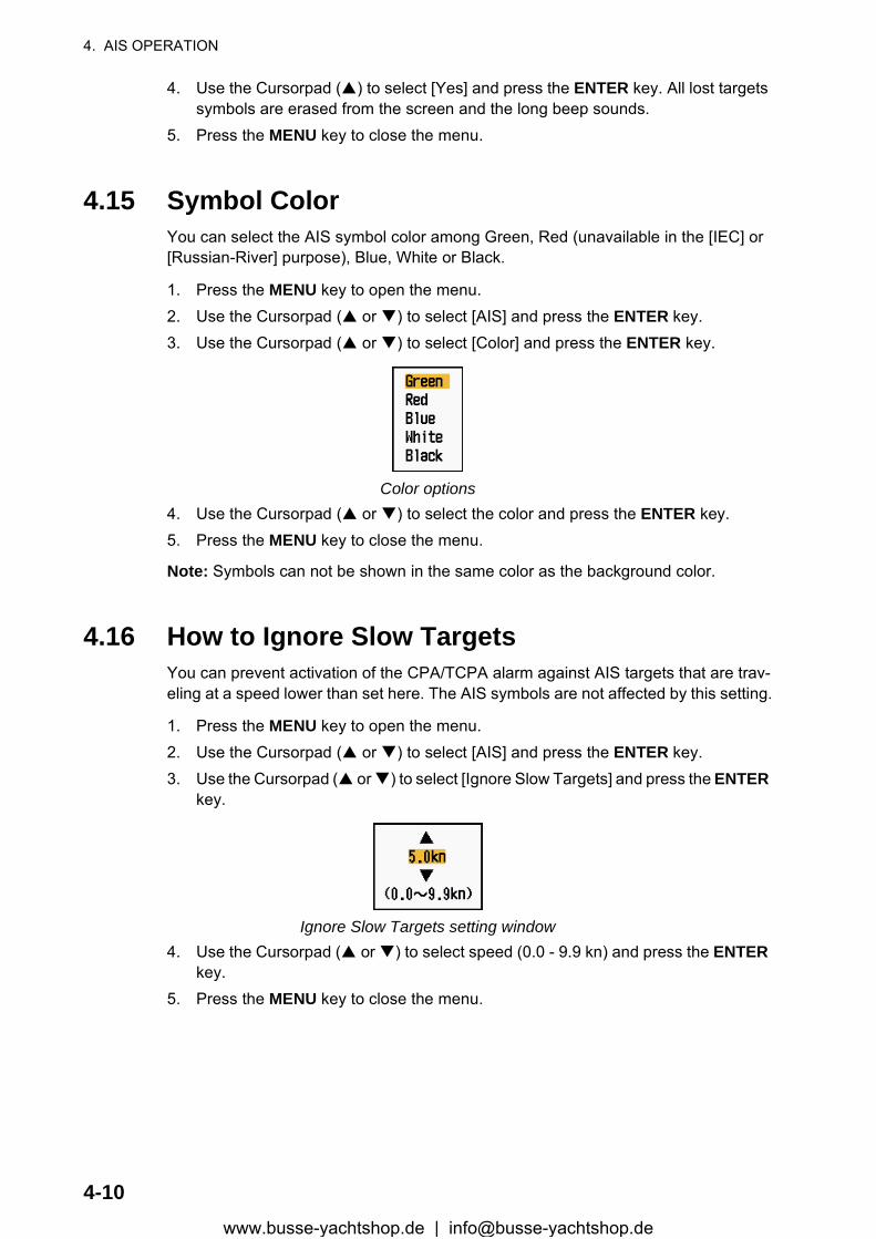
4. AIS OPERATION
4. Use the Cursorpad ( ) to select [Yes] and press the ENTER key. All lost targets symbols are erased from the screen and the long beep sounds.
5. Press the MENU key to close the menu.
4.15 Symbol ColorYou can select the AIS symbol color among Green, Red (unavailable in the [IEC] or [Russian-River] purpose), Blue, White or Black.
1. Press the MENU key to open the menu.2. Use the Cursorpad ( or ) to select [AIS] and press the ENTER key.3. Use the Cursorpad ( or ) to select [Color] and press the ENTER key.
Color options4. Use the Cursorpad ( or ) to select the color and press the ENTER key.5. Press the MENU key to close the menu.
Note: Symbols can not be shown in the same color as the background color.
4.16 How to Ignore Slow TargetsYou can prevent activation of the CPA/TCPA alarm against AIS targets that are trav-eling at a speed lower than set here. The AIS symbols are not affected by this setting.
1. Press the MENU key to open the menu.2. Use the Cursorpad ( or ) to select [AIS] and press the ENTER key.3. Use the Cursorpad ( or ) to select [Ignore Slow Targets] and press the ENTER
key.
Ignore Slow Targets setting window4. Use the Cursorpad ( or ) to select speed (0.0 - 9.9 kn) and press the ENTER
key.5. Press the MENU key to close the menu.
4-10www.busse-yachtshop.de | [email protected]
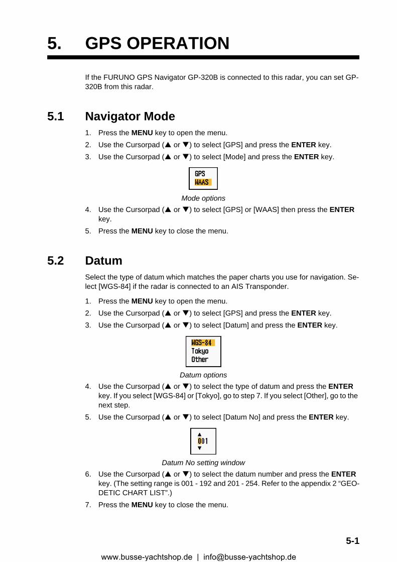
5. GPS OPERATION
If the FURUNO GPS Navigator GP-320B is connected to this radar, you can set GP-320B from this radar.
5.1 Navigator Mode1. Press the MENU key to open the menu.2. Use the Cursorpad ( or ) to select [GPS] and press the ENTER key.3. Use the Cursorpad ( or ) to select [Mode] and press the ENTER key.
Mode options4. Use the Cursorpad ( or ) to select [GPS] or [WAAS] then press the ENTER
key.5. Press the MENU key to close the menu.
5.2 DatumSelect the type of datum which matches the paper charts you use for navigation. Se-lect [WGS-84] if the radar is connected to an AIS Transponder.
1. Press the MENU key to open the menu.2. Use the Cursorpad ( or ) to select [GPS] and press the ENTER key.3. Use the Cursorpad ( or ) to select [Datum] and press the ENTER key.
Datum options4. Use the Cursorpad ( or ) to select the type of datum and press the ENTER
key. If you select [WGS-84] or [Tokyo], go to step 7. If you select [Other], go to the next step.
5. Use the Cursorpad ( or ) to select [Datum No] and press the ENTER key.
Datum No setting window6. Use the Cursorpad ( or ) to select the datum number and press the ENTER
key. (The setting range is 001 - 192 and 201 - 254. Refer to the appendix 2 “GEO-DETIC CHART LIST”.)
7. Press the MENU key to close the menu.
5-1www.busse-yachtshop.de | [email protected]
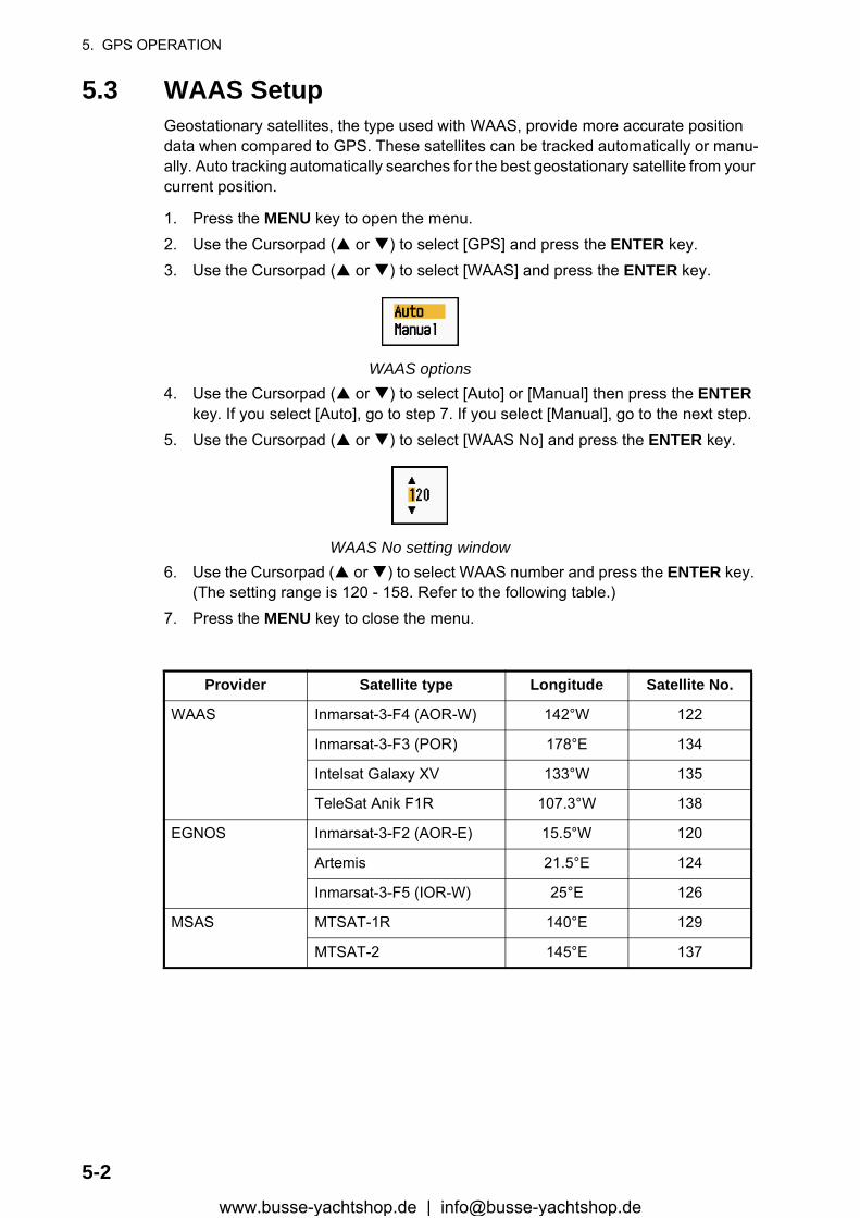
5. GPS OPERATION
5.3 WAAS SetupGeostationary satellites, the type used with WAAS, provide more accurate position data when compared to GPS. These satellites can be tracked automatically or manu-ally. Auto tracking automatically searches for the best geostationary satellite from your current position.
1. Press the MENU key to open the menu.2. Use the Cursorpad ( or ) to select [GPS] and press the ENTER key.3. Use the Cursorpad ( or ) to select [WAAS] and press the ENTER key.
WAAS options4. Use the Cursorpad ( or ) to select [Auto] or [Manual] then press the ENTER
key. If you select [Auto], go to step 7. If you select [Manual], go to the next step.5. Use the Cursorpad ( or ) to select [WAAS No] and press the ENTER key.
WAAS No setting window6. Use the Cursorpad ( or ) to select WAAS number and press the ENTER key.
(The setting range is 120 - 158. Refer to the following table.)7. Press the MENU key to close the menu.
Provider Satellite type Longitude Satellite No.
WAAS Inmarsat-3-F4 (AOR-W) 142°W 122
Inmarsat-3-F3 (POR) 178°E 134
Intelsat Galaxy XV 133°W 135
TeleSat Anik F1R 107.3°W 138
EGNOS Inmarsat-3-F2 (AOR-E) 15.5°W 120
Artemis 21.5°E 124
Inmarsat-3-F5 (IOR-W) 25°E 126
MSAS MTSAT-1R 140°E 129
MTSAT-2 145°E 137
5-2www.busse-yachtshop.de | [email protected]
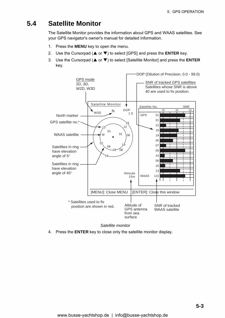
5. GPS OPERATION
5.4 Satellite MonitorThe Satellite Monitor provides the information about GPS and WAAS satellites. See your GPS navigator's owner's manual for detailed information.
1. Press the MENU key to open the menu.2. Use the Cursorpad ( or ) to select [GPS] and press the ENTER key.3. Use the Cursorpad ( or ) to select [Satellite Monitor] and press the ENTER
key.
Satellite monitor4. Press the ENTER key to close only the satellite monitor display.
06
W3DDOP
1.5
15m
13
Altitude
01GPS
WAAS
12
24
16
SNRSatellite No.30 40 50
122
01
31
18
19
06
07
09
08
13
North marker
DOP (Dilution of Precision, 0.0 - 99.0)
SNR of tracked GPS satellitesSatellites whose SNR is above40 are used to fix position.
GPS mode2D, 3D,W2D, W3D
GPS satellite no.*
WAAS satellite
Satellites in ring have elevationangle of 5°
Satellites in ring have elevationangle of 45°
Altitude ofGPS antennafrom seasurface
SNR of trackedWAAS satellite
W
N
[MENU]: Close MENU [ENTER]: Close this window
* Satellites used to fix position are shown in red.
Satel l i te Monitor
01
09
2412
19
18
07
13
16
08
31
5-3www.busse-yachtshop.de | [email protected]
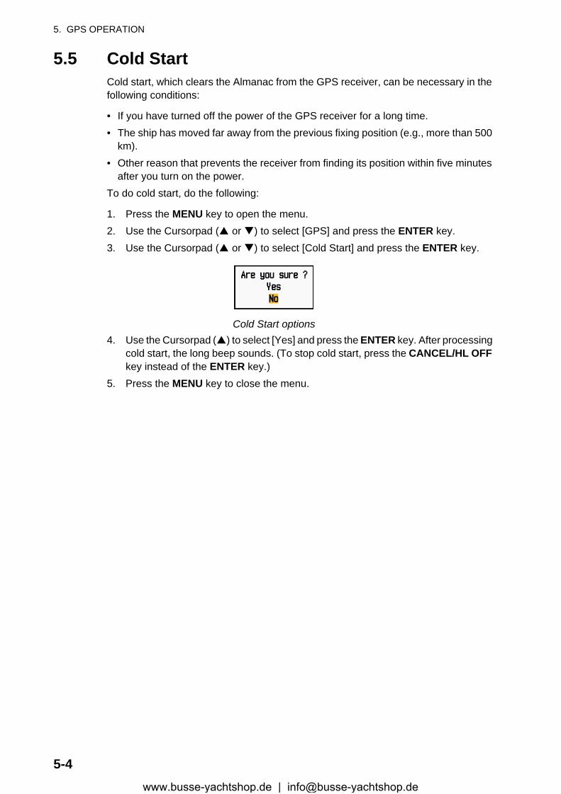
5. GPS OPERATION
5.5 Cold StartCold start, which clears the Almanac from the GPS receiver, can be necessary in the following conditions:
• If you have turned off the power of the GPS receiver for a long time.• The ship has moved far away from the previous fixing position (e.g., more than 500
km).• Other reason that prevents the receiver from finding its position within five minutes
after you turn on the power.To do cold start, do the following:
1. Press the MENU key to open the menu.2. Use the Cursorpad ( or ) to select [GPS] and press the ENTER key.3. Use the Cursorpad ( or ) to select [Cold Start] and press the ENTER key.
Cold Start options4. Use the Cursorpad ( ) to select [Yes] and press the ENTER key. After processing
cold start, the long beep sounds. (To stop cold start, press the CANCEL/HL OFF key instead of the ENTER key.)
5. Press the MENU key to close the menu.
5-4www.busse-yachtshop.de | [email protected]
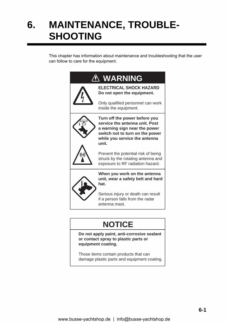
6. MAINTENANCE, TROUBLE-SHOOTING
This chapter has information about maintenance and troubleshooting that the user can follow to care for the equipment.
WARNINGELECTRICAL SHOCK HAZARDDo not open the equipment.
Only qualified personnel can workinside the equipment.
Turn off the power before youservice the antenna unit. Posta warning sign near the powerswitch not to turn on the powerwhile you service the antennaunit.
Prevent the potential risk of beingstruck by the rotating antenna andexposure to RF radiation hazard.
When you work on the antennaunit, wear a safety belt and hardhat.
Serious injury or death can resultif a person falls from the radarantenna mast.
NOTICEDo not apply paint, anti-corrosive sealantor contact spray to plastic parts orequipment coating.
Those items contain products that candamage plastic parts and equipment coating.
6-1www.busse-yachtshop.de | [email protected]

6. MAINTENANCE, TROUBLESHOOTING
6.1 Preventive MaintenanceRegular maintenance helps keep your equipment in good condition and prevents fu-ture problems. Check the items shown in the table below to help keep your equipment in good condition for years to come.
Maintenance
Interval Item Check point Remedy
Whennecessary
LCD Dust on the LCD Remove the dust from the LCD with the tissue paper and an LCD cleaner. To remove dirt or salt, use the LCD cleaner. Change the tis-sue paper often so as not to scratch the LCD.
3 to 6months
Ground terminal on display unit
Check for tight connec-tion and rust.
Tighten or replace as necessary.
Display unitconnectors
Check for tight connec-tion.
Tighten if the connectors are loos-ened.
Exposed nuts and bolts on the anten-na unit
Check for corroded or loosened bolts.
Clean and repaint as necessary. Use sealing compound instead of paint.
Antenna radiator Check for dirt and cracks on the radiator surface.
Clean radiator surface with fresh-water-moistened cloth. Do not use plastic solvents to clean.
6-2www.busse-yachtshop.de | [email protected]
6. MAINTENANCE, TROUBLESHOOTING
6.2 Fuse ReplacementThe fuse on the power cable protects the equipment from overcurrent and equipment fault. If the fuse blows, find the cause before you replace the fuse. Use the correct fuse. A wrong fuse can damage the equipment.
6.3 Magnetron LifeWhen the life of the magnetron is reached, the targets do not appear on the display. If long-range performance appears to have decreased, contact a FURUNO agent or dealer about replacement of the magnetron.
6.4 LCD Backlight LifeThe life of the LCD backlight, which provides illumination for the LCD, is approximately 4,800 hours at 25°C (ambient temperature). The display brilliance cannot be raised when the backlight has worn out. When brilliance cannot be raised, have a qualified technician replace the backlight.
Unit Type Code No. Remarks
Display unit (fitted on power cable)
FGB0 125V 10A PBF 000-155-826-10 12 VDC
FGB0-A 125V 5A PBF 000-155-853-10 24 VDC
Model Magnetron type Code No. Estimated life
MODEL 1835 MODEL 1935
MAF1421B 000-158-786-10 Approx. 3,000 hours
MG4004 000-158-895-10 Approx. 3,000 hours
E3571 000-146-867-01 Approx. 2,000 hours
MODEL 1945MAF1422B 000-158-788-10 Approx. 3,000 hours
MG4006 000-158-896-10 Approx. 3,000 hours
Name Type Code No.
Lamp holder complete set 104LHS46 000-160-949-10
WARNINGUse the correct fuse.
A wrong fuse can damage the equipmentand cause fire.
6-3www.busse-yachtshop.de | [email protected]
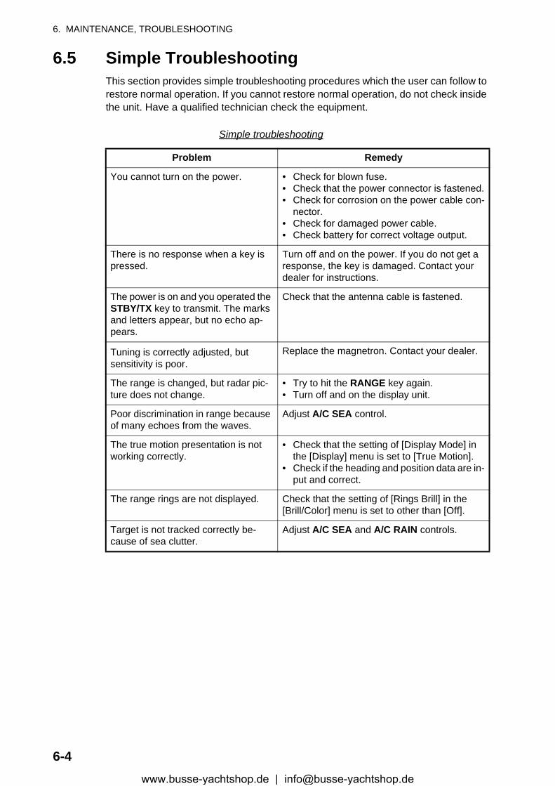
6. MAINTENANCE, TROUBLESHOOTING
6.5 Simple TroubleshootingThis section provides simple troubleshooting procedures which the user can follow to restore normal operation. If you cannot restore normal operation, do not check inside the unit. Have a qualified technician check the equipment.
Simple troubleshooting
Problem Remedy
You cannot turn on the power. • Check for blown fuse.• Check that the power connector is fastened.• Check for corrosion on the power cable con-
nector.• Check for damaged power cable.• Check battery for correct voltage output.
There is no response when a key is pressed.
Turn off and on the power. If you do not get a response, the key is damaged. Contact your dealer for instructions.
The power is on and you operated the STBY/TX key to transmit. The marks and letters appear, but no echo ap-pears.
Check that the antenna cable is fastened.
Tuning is correctly adjusted, but sensitivity is poor.
Replace the magnetron. Contact your dealer.
The range is changed, but radar pic-ture does not change.
• Try to hit the RANGE key again.• Turn off and on the display unit.
Poor discrimination in range because of many echoes from the waves.
Adjust A/C SEA control.
The true motion presentation is not working correctly.
• Check that the setting of [Display Mode] in the [Display] menu is set to [True Motion].
• Check if the heading and position data are in-put and correct.
The range rings are not displayed. Check that the setting of [Rings Brill] in the [Brill/Color] menu is set to other than [Off].
Target is not tracked correctly be-cause of sea clutter.
Adjust A/C SEA and A/C RAIN controls.
6-4www.busse-yachtshop.de | [email protected]
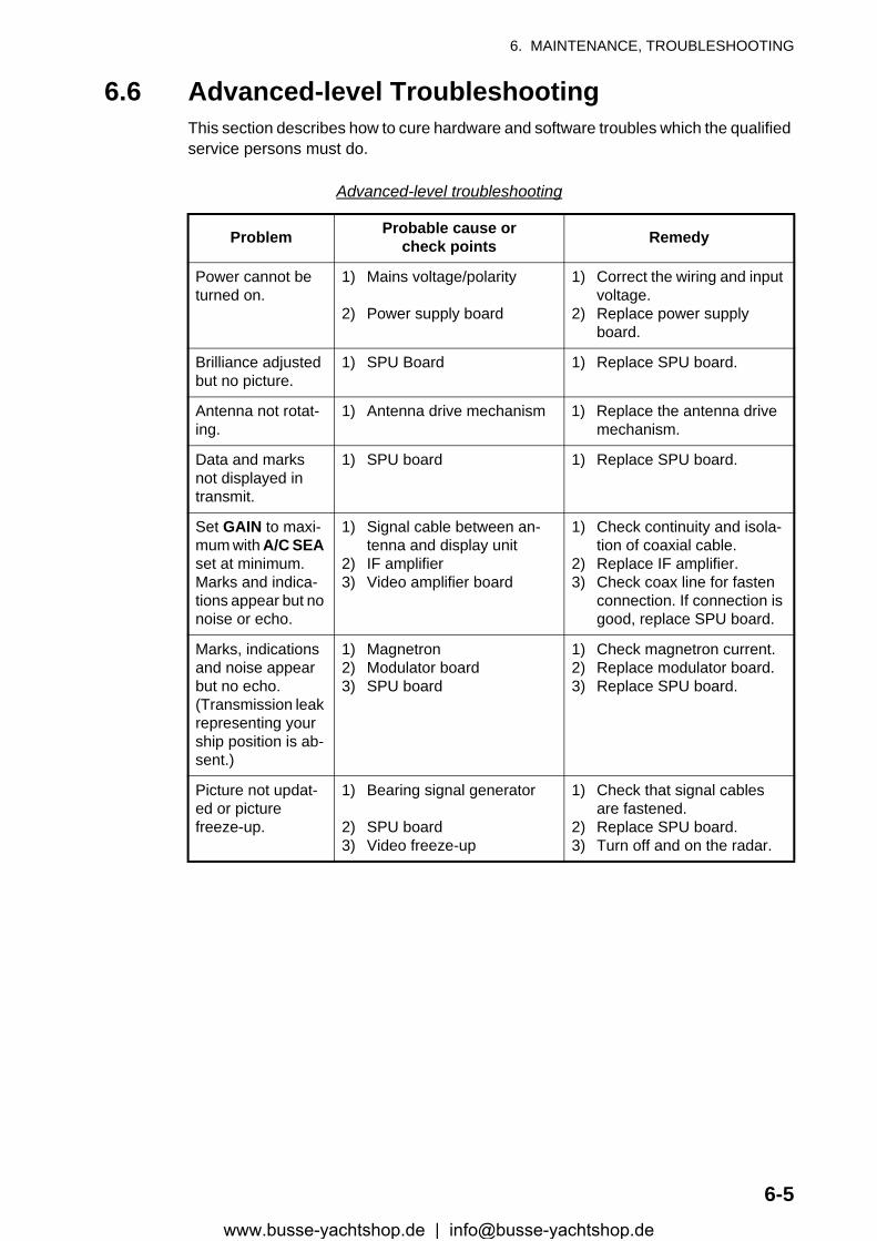
6. MAINTENANCE, TROUBLESHOOTING
6.6 Advanced-level TroubleshootingThis section describes how to cure hardware and software troubles which the qualified service persons must do.
Advanced-level troubleshooting
Problem Probable cause orcheck points Remedy
Power cannot be turned on.
1) Mains voltage/polarity
2) Power supply board
1) Correct the wiring and input voltage.
2) Replace power supply board.
Brilliance adjusted but no picture.
1) SPU Board 1) Replace SPU board.
Antenna not rotat-ing.
1) Antenna drive mechanism 1) Replace the antenna drive mechanism.
Data and marks not displayed in transmit.
1) SPU board 1) Replace SPU board.
Set GAIN to maxi-mum with A/C SEA set at minimum. Marks and indica-tions appear but no noise or echo.
1) Signal cable between an-tenna and display unit
2) IF amplifier3) Video amplifier board
1) Check continuity and isola-tion of coaxial cable.
2) Replace IF amplifier.3) Check coax line for fasten
connection. If connection is good, replace SPU board.
Marks, indications and noise appear but no echo. (Transmission leak representing your ship position is ab-sent.)
1) Magnetron2) Modulator board3) SPU board
1) Check magnetron current.2) Replace modulator board.3) Replace SPU board.
Picture not updat-ed or picture freeze-up.
1) Bearing signal generator
2) SPU board3) Video freeze-up
1) Check that signal cables are fastened.
2) Replace SPU board.3) Turn off and on the radar.
6-5www.busse-yachtshop.de | [email protected]
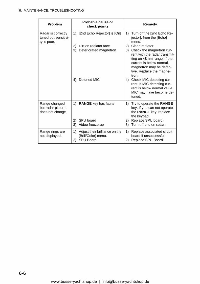
6. MAINTENANCE, TROUBLESHOOTING
Radar is correctly tuned but sensitivi-ty is poor.
1) [2nd Echo Rejector] is [On]
2) Dirt on radiator face3) Deteriorated magnetron
4) Detuned MIC
1) Turn off the [2nd Echo Re-jector], from the [Echo] menu.
2) Clean radiator.3) Check the magnetron cur-
rent with the radar transmit-ting on 48 nm range. If the current is below normal, magnetron may be defec-tive. Replace the magne-tron.
4) Check MIC detecting cur-rent. If MIC detecting cur-rent is below normal value, MIC may have become de-tuned.
Range changed but radar picture does not change.
1) RANGE key has faults
2) SPU board3) Video freeze-up
1) Try to operate the RANGE key. If you can not operate the RANGE key, replace the keypad.
2) Replace SPU board.3) Turn off and on radar.
Range rings are not displayed.
1) Adjust their brilliance on the [Brill/Color] menu.
2) SPU Board
1) Replace associated circuit board if unsuccessful.
2) Replace SPU Board.
Problem Probable cause orcheck points Remedy
6-6www.busse-yachtshop.de | [email protected]
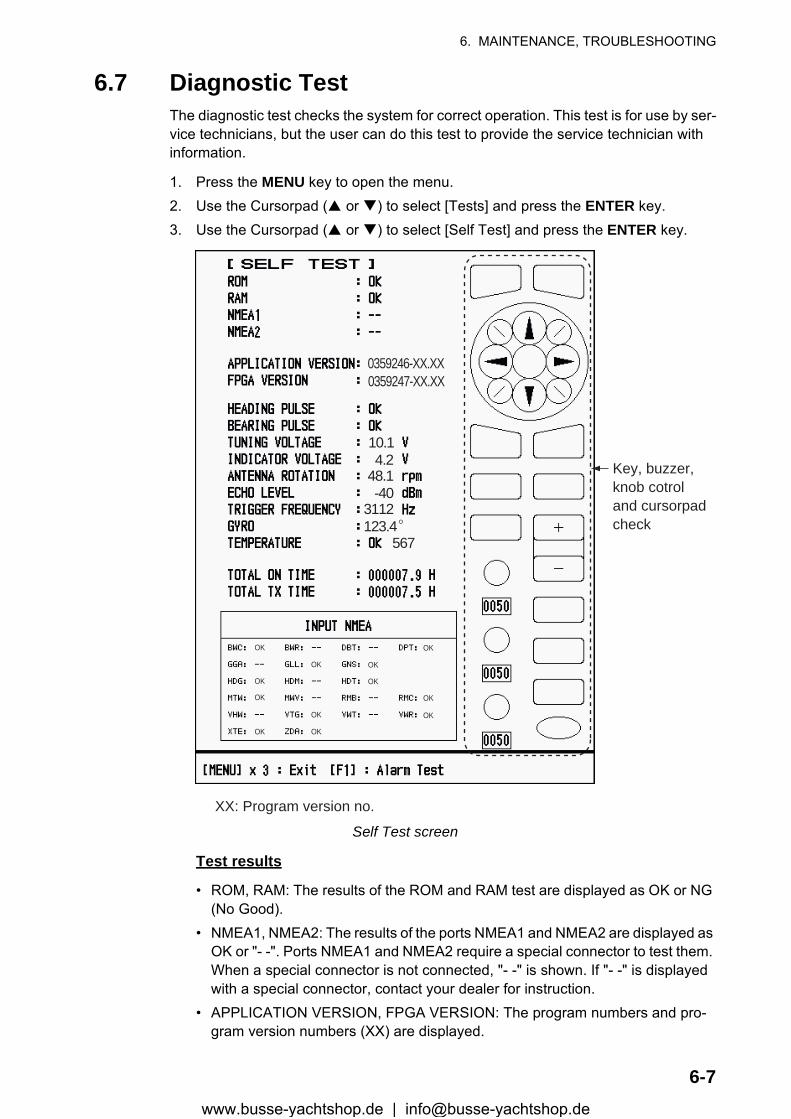
6. MAINTENANCE, TROUBLESHOOTING
6-7
6.7 Diagnostic TestThe diagnostic test checks the system for correct operation. This test is for use by ser-vice technicians, but the user can do this test to provide the service technician with information.
1. Press the MENU key to open the menu.2. Use the Cursorpad ( or ) to select [Tests] and press the ENTER key.3. Use the Cursorpad ( or ) to select [Self Test] and press the ENTER key.
Self Test screen
Test results
• ROM, RAM: The results of the ROM and RAM test are displayed as OK or NG (No Good).
• NMEA1, NMEA2: The results of the ports NMEA1 and NMEA2 are displayed as OK or "- -". Ports NMEA1 and NMEA2 require a special connector to test them. When a special connector is not connected, "- -" is shown. If "- -" is displayed with a special connector, contact your dealer for instruction.
• APPLICATION VERSION, FPGA VERSION: The program numbers and pro-gram version numbers (XX) are displayed.
XX: Program version no.
0359246-XX.XX0359247-XX.XX
10.14.2
48.1-40
3112123.4°
567
OK
OK
OK
OK
OK
OK
OK
OK
OK
OK
OK
OK
Key, buzzer,knob cotroland cursorpadcheck
www.busse-yachtshop.de | [email protected]
6. MAINTENANCE, TROUBLESHOOTING
6-8
• HEADING PULSE, BEARING PULSE: The results of the pulse input are dis-played as OK or NG. When [Antenna Rotation] is set to [Stop], or [Watchman] is set to [Off] in the STBY mode, this test is skipped and "- -" is shown for both heading and bearing.
• TUNING VOLTAGE, INDICATOR VOLTAGE, ANTENNA ROTATION, ECHO LEVEL, TRIGGER FREQUENCY: The results of measurement are displayed.
• GYRO: The current gyrocompass reading is displayed.• TEMPERATURE: The result of the temperature test is displayed as OK or NG
and the temperature is measured and shown.• TOTAL ON TIME, TOTAL TX TIME: The total number of hours, for which the
radar has been powered and transmitted, are displayed.• INPUT NMEA window: The condition of all the NMEA sentences being input to
this radar are displayed as OK or "- -". "- -" means no data input. Sentences are updated every second.
Key check
Press each key one by one. A key’s on-screen location becomes green if the key is normal.
Buzzer check
The F1 key tests on/off for the panel buzzer or external buzzer. To stop the buzz-er, press the F1 key again.
Knob control check
Rotate each control knob. The four digits below the on-screen location for the GAIN, A/C SEA and A/C RAIN knob controls show the control position. Press each knob. The knob corresponding on-screen circle changes in green if the knob is normal.
Cursorpad check
Press each arrow and diagonal dot one by one. The on-screen location changes in green if the key is normal.
4. Press the MENU key three times to escape from the test.5. Press the MENU key to close the menu.
www.busse-yachtshop.de | [email protected]
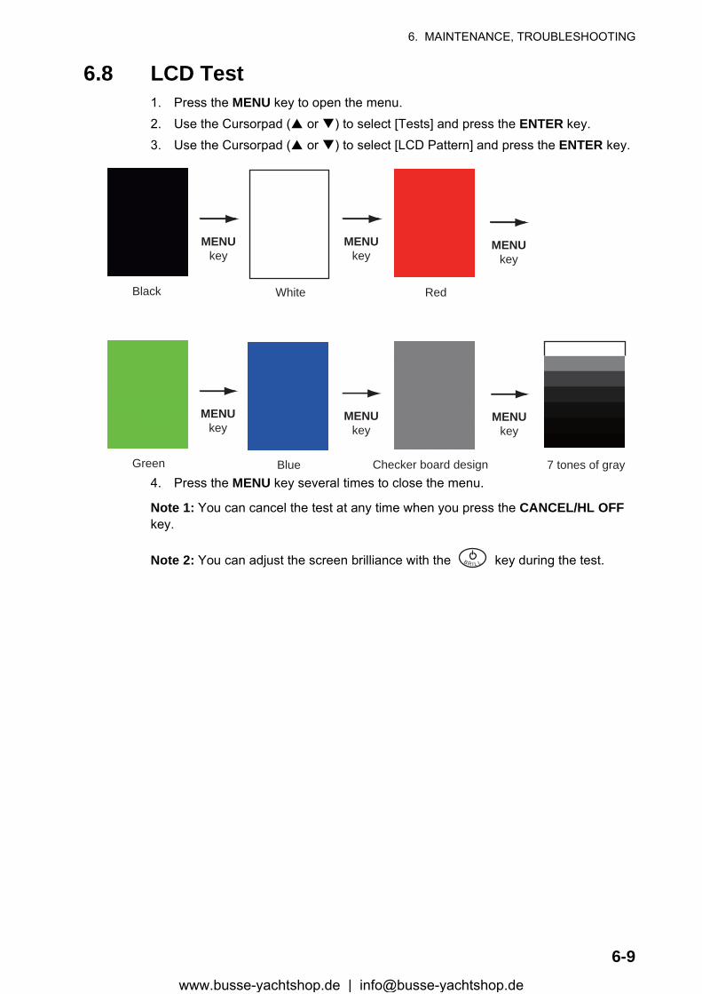
6. MAINTENANCE, TROUBLESHOOTING
6-9
6.8 LCD Test1. Press the MENU key to open the menu.2. Use the Cursorpad ( or ) to select [Tests] and press the ENTER key.3. Use the Cursorpad ( or ) to select [LCD Pattern] and press the ENTER key.
4. Press the MENU key several times to close the menu.
Note 1: You can cancel the test at any time when you press the CANCEL/HL OFF key.
Note 2: You can adjust the screen brilliance with the key during the test.
Black
MENUkey
MENUkey
MENUkey
MENUkey
MENUkey
MENUkey
White Red
Green Blue Checker board design 7 tones of gray
B R I L L
www.busse-yachtshop.de | [email protected]
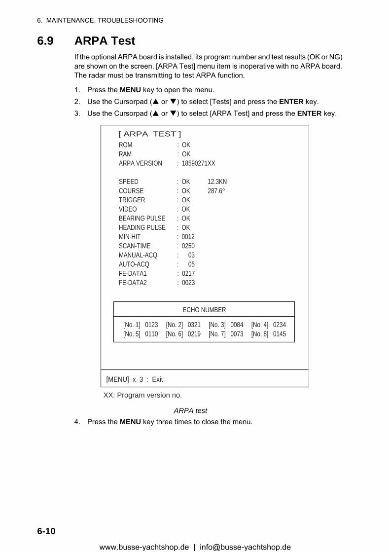
6. MAINTENANCE, TROUBLESHOOTING
6-10
6.9 ARPA TestIf the optional ARPA board is installed, its program number and test results (OK or NG) are shown on the screen. [ARPA Test] menu item is inoperative with no ARPA board. The radar must be transmitting to test ARPA function.
1. Press the MENU key to open the menu.2. Use the Cursorpad ( or ) to select [Tests] and press the ENTER key.3. Use the Cursorpad ( or ) to select [ARPA Test] and press the ENTER key.
ARPA test4. Press the MENU key three times to close the menu.
XX: Program version no.
[ ARPA TEST ]ROM : OKRAM : OKARPA VERSION : 18590271XX
SPEED : OK 12.3KNCOURSE : OK 287.6°TRIGGER : OKVIDEO : OKBEARING PULSE : OKHEADING PULSE : OKMIN-HIT : 0012SCAN-TIME : 0250MANUAL-ACQ : 03AUTO-ACQ : 05FE-DATA1 : 0217FE-DATA2 : 0023
ECHO NUMBER
[No. 1] 0123 [No. 2] 0321 [No. 3] 0084 [No. 4] 0234[No. 5] 0110 [No. 6] 0219 [No. 7] 0073 [No. 8] 0145
[MENU] x 3 : Exit
www.busse-yachtshop.de | [email protected]
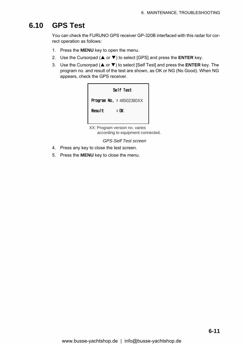
6. MAINTENANCE, TROUBLESHOOTING
6-11
6.10 GPS TestYou can check the FURUNO GPS receiver GP-320B interfaced with this radar for cor-rect operation as follows:
1. Press the MENU key to open the menu.2. Use the Cursorpad ( or ) to select [GPS] and press the ENTER key.3. Use the Cursorpad ( or ) to select [Self Test] and press the ENTER key. The
program no. and result of the test are shown, as OK or NG (No Good). When NG appears, check the GPS receiver.
GPS-Self Test screen4. Press any key to close the test screen.5. Press the MENU key to close the menu.
48502380XX
XX: Program version no. varies according to equipment connected.
www.busse-yachtshop.de | [email protected]

6. MAINTENANCE, TROUBLESHOOTING
6-12
This page is intentionally left blank.
www.busse-yachtshop.de | [email protected]
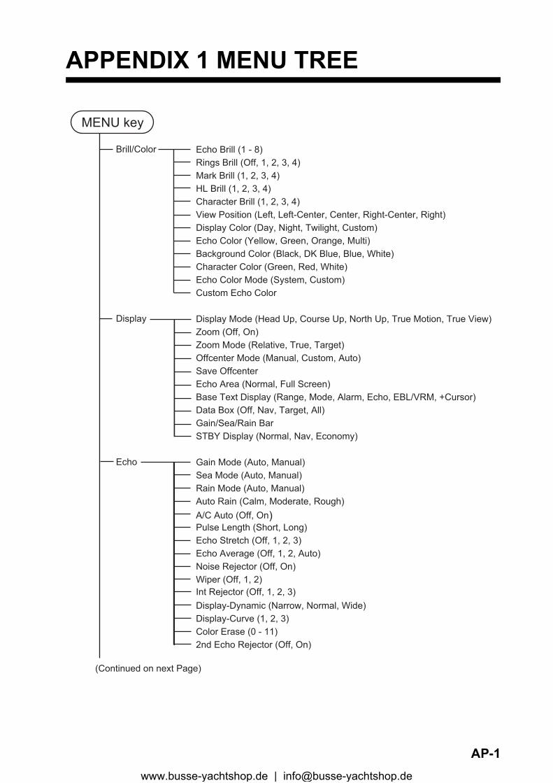
APPENDIX 1 MENU TREE
MENU key
Brill/Color
Display
Echo
Echo Brill (1 - 8)Rings Brill (Off, 1, 2, 3, 4)Mark Brill (1, 2, 3, 4)HL Brill (1, 2, 3, 4)Character Brill (1, 2, 3, 4)View Position (Left, Left-Center, Center, Right-Center, Right)Display Color (Day, Night, Twilight, Custom)Echo Color (Yellow, Green, Orange, Multi)Background Color (Black, DK Blue, Blue, White)Character Color (Green, Red, White)Echo Color Mode (System, Custom)Custom Echo Color
Display Mode (Head Up, Course Up, North Up, True Motion, True View)Zoom (Off, On)Zoom Mode (Relative, True, Target)Offcenter Mode (Manual, Custom, Auto) Save OffcenterEcho Area (Normal, Full Screen)Base Text Display (Range, Mode, Alarm, Echo, EBL/VRM, +Cursor)Data Box (Off, Nav, Target, All)Gain/Sea/Rain BarSTBY Display (Normal, Nav, Economy)
Gain Mode (Auto, Manual)Sea Mode (Auto, Manual)Rain Mode (Auto, Manual)Auto Rain (Calm, Moderate, Rough)A/C Auto (Off, On)Pulse Length (Short, Long)Echo Stretch (Off, 1, 2, 3)Echo Average (Off, 1, 2, Auto)Noise Rejector (Off, On)Wiper (Off, 1, 2)Int Rejector (Off, 1, 2, 3)Display-Dynamic (Narrow, Normal, Wide)Display-Curve (1, 2, 3)Color Erase (0 - 11)2nd Echo Rejector (Off, On)
(Continued on next Page)
AP-1www.busse-yachtshop.de | [email protected]
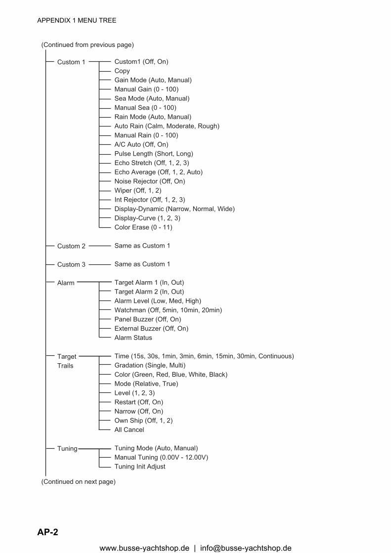
APPENDIX 1 MENU TREE
(Continued from previous page)
Custom 1
Custom 2
Custom 3
Alarm
TargetTrails
Tuning
Custom1 (Off, On)CopyGain Mode (Auto, Manual)Manual Gain (0 - 100)Sea Mode (Auto, Manual)Manual Sea (0 - 100)Rain Mode (Auto, Manual)Auto Rain (Calm, Moderate, Rough)Manual Rain (0 - 100)A/C Auto (Off, On)Pulse Length (Short, Long)Echo Stretch (Off, 1, 2, 3)Echo Average (Off, 1, 2, Auto)Noise Rejector (Off, On)Wiper (Off, 1, 2)Int Rejector (Off, 1, 2, 3)Display-Dynamic (Narrow, Normal, Wide)Display-Curve (1, 2, 3)Color Erase (0 - 11)
Same as Custom 1
Same as Custom 1
Target Alarm 1 (In, Out)Target Alarm 2 (In, Out)Alarm Level (Low, Med, High)Watchman (Off, 5min, 10min, 20min)Panel Buzzer (Off, On)External Buzzer (Off, On)Alarm Status
Time (15s, 30s, 1min, 3min, 6min, 15min, 30min, Continuous)Gradation (Single, Multi)Color (Green, Red, Blue, White, Black)Mode (Relative, True)Level (1, 2, 3)Restart (Off, On)Narrow (Off, On)Own Ship (Off, 1, 2)All Cancel
Tuning Mode (Auto, Manual)Manual Tuning (0.00V - 12.00V)Tuning Init Adjust
(Continued on next page)
AP-2www.busse-yachtshop.de | [email protected]
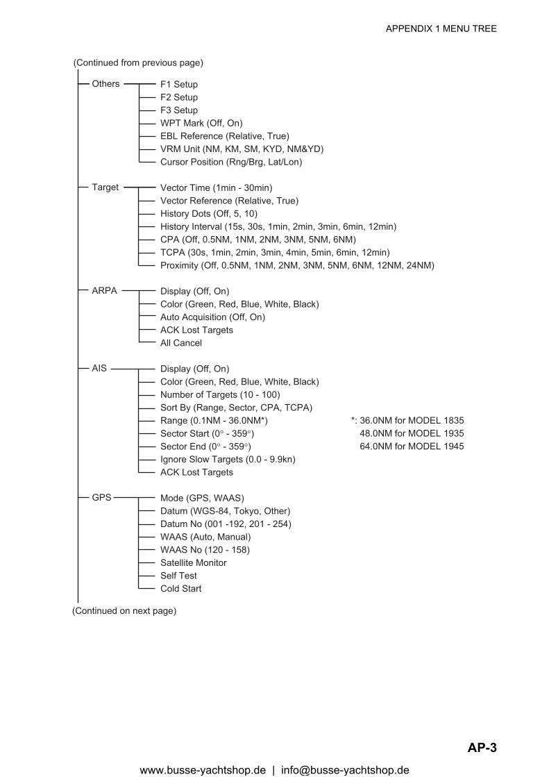
APPENDIX 1 MENU TREE
(Continued from previous page)
Others
Target
ARPA
AIS
GPS
F1 SetupF2 SetupF3 SetupWPT Mark (Off, On)EBL Reference (Relative, True)VRM Unit (NM, KM, SM, KYD, NM&YD)Cursor Position (Rng/Brg, Lat/Lon)
Vector Time (1min - 30min) Vector Reference (Relative, True)History Dots (Off, 5, 10)History Interval (15s, 30s, 1min, 2min, 3min, 6min, 12min)CPA (Off, 0.5NM, 1NM, 2NM, 3NM, 5NM, 6NM)TCPA (30s, 1min, 2min, 3min, 4min, 5min, 6min, 12min)Proximity (Off, 0.5NM, 1NM, 2NM, 3NM, 5NM, 6NM, 12NM, 24NM)
Display (Off, On)Color (Green, Red, Blue, White, Black)Auto Acquisition (Off, On)ACK Lost TargetsAll Cancel
Display (Off, On)Color (Green, Red, Blue, White, Black)Number of Targets (10 - 100)Sort By (Range, Sector, CPA, TCPA)Range (0.1NM - 36.0NM*)Sector Start (0° - 359°)Sector End (0° - 359°)Ignore Slow Targets (0.0 - 9.9kn)ACK Lost Targets
Mode (GPS, WAAS)Datum (WGS-84, Tokyo, Other)Datum No (001 -192, 201 - 254)WAAS (Auto, Manual)WAAS No (120 - 158)Satellite MonitorSelf TestCold Start
(Continued on next page)
*: 36.0NM for MODEL 1835 48.0NM for MODEL 1935 64.0NM for MODEL 1945
AP-3www.busse-yachtshop.de | [email protected]

APPENDIX 1 MENU TREE
(Continued from previous page)
System Initial
Tests
SectorBlanks
Units
Installation (For use by the installer. Not accessibile by user.)
Factory (For use by the installer. Not accessibile by user.)
Key Beep (Off, On)Offcenter Speed (1kn - 99kn)Compass Type (Magnetic, True)Range PresetWind Direction (Apparent, True)NMEA Port 1 (Auto, 4800bps, 38400bps)NMEA Port 2 (Auto, 4800bps, 38400bps)NMEA Mixing Out (Off, On)
Self TestLCD PatternARPA Test
Sect-Blank 1 Status (Off, On)Sect-Blank 1 Start (0° - 359°)Sect-Blank 1 End (0° - 359°)Sect-Blank 2 Status (Off, On)Sect-Blank 2 Start (0° - 359°)Sect-Blank 2 End (0° - 359°)
Range Unit (NM, KM, SM)Ship Speed Unit (kn, km/h, mph)Depth Unit (m, ft, fa, pb, HR)Temperature Unit (°C, °F)Wind Speed Unit (kn, km/h, mph, m/s)
AP-4www.busse-yachtshop.de | [email protected]
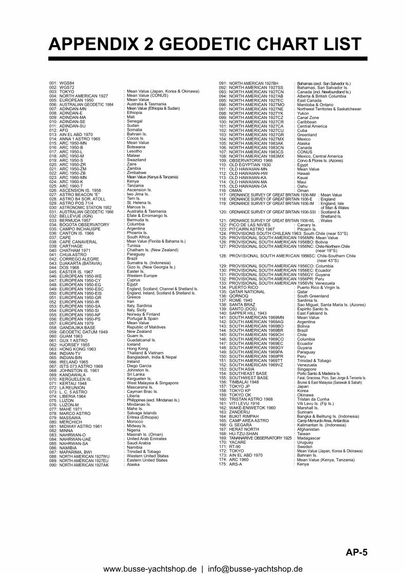
APPENDIX 2 GEODETIC CHART LIST
001: WGS84 002: WGS72 003: TOKYO : 004: NORTH AMERICAN 1927 : Mean Value (CONUS) 005: EUROPEAN 1950 : Mean Value 006: AUSTRALIAN GEODETIC 1984 : Australia & Tasmania 007: ADINDAN-MN : Mean Value (Ethiopia & Sudan) 008: ADINDAN-E : Ethiopia 009: ADINDAN-MA : Mali 010: ADINDAN-SE : Senegal 011: ADINDAN-SU : Sudan 012: AFG : Somalia 013: AIN EL ABD 1970 : Bahrain Is. 014: ANNA 1 ASTRO 1965 : Cocos Is. 015: ARC 1950-MN : Mean Value 016: ARC 1950-B : Botswana 017: ARC 1950-L : Lesotho 018: ARC 1950-M : Malawi 019: ARC 1950-S : Swaziland 020: ARC 1950-ZR : Zaire 021: ARC 1950-ZM : Zambia 022: ARC 1950-ZB : Zimbabwe 023: ARC 1960-MN : Mean Value (Kenya & Tanzania) 024: ARC 1960-K : Kenya 025: ARC 1960-T : Tanzania 026: ASCENSION IS. 1958 : Ascension Is. 027: ASTRO BEACON “E” : Iwo Jima Is. 028: ASTRO B4 SOR. ATOLL : Tern Is. 029: ASTRO POS 71/4 : St. Helena Is. 030: ASTRONOMIC STATION 1952 : Marcus Is. 031: AUSTRALIAN GEODETIC 1966 : Australia & Tasmania 032: BELLEVUE (IGN) : Efate & Erromango Is.033: BERMUDA 1957 : Bermuda Is.034: BOGOTA OBSERVATORY : Columbia 035: CAMPO INCHAUSPE : Argentina 036: CANTON IS. 1966 : Phoenix Is.037: CAPE : South Africa 038: CAPE CANAVERAL : 039: CARTHAGE : Tunisia 040: CHATHAM 1971 : Chatham Is. (New Zealand) 041: CHUA ASTRO : Paraguay 042: CORREGO ALEGRE : Brazil 043: DJAKARTA (BATAVIA) : Sumatra Is. (Indonesia) 044: DOS 1968 : Gizo Is. (New Georgia Is.) 045: EASTER IS. 1967 : Easter Is. 046: EUROPEAN 1950-WE : Western Europe 047: EUROPEAN 1950-CY : Cyprus 048: EUROPEAN 1950-EG : Egypt 049: EUROPEAN 1950-ESC : 050: EUROPEAN 1950-EIS : 051: EUROPEAN 1950-GR : Greece 052 EUROPEAN 1950-IR : Iran 053: EUROPEAN 1950-SA : Italy, Sardinia 054: EUROPEAN 1950-SI : Italy, Sicily 055: EUROPEAN 1950-NF : Norway & Finland 056: EUROPEAN 1950-PS : Portugal & Spain 057: EUROPEAN 1979 : Mean Value 058: GANDAJIKA BASE : Republic of Maldives 059: GEODETIC DATUM 1949 : New Zealand 060: GUAM 1963 : Guam Is. 061: GUX 1 ASTRO : Guadalcanal Is. 062: HJORSEY 1955 : Iceland 063: HONG KONG 1963 : Hong Kong 064: INDIAN-TV : Thailand & Vietnam 065: INDIAN-BIN : Bangladesh, India & Nepal 066: IRELAND 1965 : Ireland 067: ISTS 073 ASTRO 1969 : Diego Garcia 068: JOHNSTON IS. 1961 : Johnston Is. 069: KANDAWALA : Sri Lanka 070: KERGUELEN IS. : Kerguelen Is. 071: KERTAU 1948 : West Malaysia & Singapore 072: LA REUNION : Mascarene Is. 073: L. C. 5 ASTRO : Cayman Brac Is. 074: LIBERIA 1964 : Liberia 075: LUZON : Philippines (excl. Mindanao Is.) 076: LUZON-M : Mindanao Is. 077: MAHE 1971 : Mahe Is. 078: MARCO ASTRO : Salvage Islands 079: MASSAWA : Eritrea (Ethiopia) 080: MERCHICH : Morocco 081: MIDWAY ASTRO 1961 : Midway Is. 082: MINNA : Nigeria 083: NAHRWAN-O : Masirah Is. (Oman) 084: NAHRWAN-UAE : United Arab Emirates 085: NAHRWAN-SA : Saudi Arabia 086: NAMIBIA : Namibia 087: MAPARIMA, BWI : Trinidad & Tobago 088: NORTH AMERICAN 1927WU : Western United States 089: NORTH AMERICAN 1927EU : Eastern United States 090: NORTH AMERICAN 1927AK : Alaska
091: NORTH AMERICAN 1927BH : Bahamas (excl. San Salvador Is.)
Mean Value (Japan, Korea & Okinawa)
Mean Value (Florida & Bahama Is.)
England, Scotland, Channel & Shetland Is.England, Ireland, Scotland & Shetland Is.
092: NORTH AMERICAN 1927SS : Bahamas, San Salvador Is. 093: NORTH AMERICAN 1927CN : Canada (incl. Newfoundland Is.) 094: NORTH AMERICAN 1927AB : Alberta & British Columbia 095: NORTH AMERICAN 1927EC : East Canada 096: NORTH AMERICAN 1927MO : Manitoba & Ontario 097: NORTH AMERICAN 1927NE : 098: NORTH AMERICAN 1927YK : Yukon 099: NORTH AMERICAN 1927CZ : Canal Zone 100: NORTH AMERICAN 1927CR : Caribbean 101: NORTH AMERICAN 1927CA : Central America 102: NORTH AMERICAN 1927CU : Cuba 103: NORTH AMERICAN 1927GR : Greenland 104: NORTH AMERICAN 1927MX : Mexico 105: NORTH AMERICAN 1983AK : Alaska 106: NORTH AMERICAN 1983CN : Canada 107: NORTH AMERICAN 1983CS : CONUS 108: NORTH AMERICAN 1983MX : Mexico, Central America 109: OBSERVATORIO 1966 : Corvo & Flores Is. (Azores)110: OLD EGYPTIAN 1930 : Egypt 111: OLD HAWAIIAN-MN : Mean Value 112: OLD HAWAIIAN-HW : Hawaii 113: OLD HAWAIIAN-KA : Kauai 114: OLD HAWAIIAN-MA : Maui 115: OLD HAWAIIAN-OA : Oahu 116: OMAN : Oman 117: ORDNANCE SURVEY OF GREAT BRITAIN 1936-NM : Mean Value118: ORDNANCE SURVEY OF GREAT BRITAIN 1936-E : England119: ORDNANCE SURVEY OF GREAT BRITAIN 1936-IM : England, Isle
of Man & Wales 120: ORDNANCE SURVEY OF GREAT BRITAIN 1936-SSI : Scotland &
Shetland Is. 121: ORDNANCE SURVEY OF GREAT BRITAIN 1936-WL : Wales122: PICO DE LAS NIVIES : Canary Is.123: PITCAIRN ASTRO 1967 : Pitcairn Is. 124: PROVISIONS SOUTH CHILEAN 1963: South Chile (near 53°S) 125: PROVISIONAL SOUTH AMERICAN 1956MN: Mean Value 126: PROVISIONAL SOUTH AMERICAN 1956BO: Bolivia 127: PROVISIONAL SOUTH AMERICAN 1956NC: Chile-Northern Chile
(near 19°S) 128: PROVISIONAL SOUTH AMERICAN 1956SC: Chile-Southern Chile
(near 43°S)
129: PROVISIONAL SOUTH AMERICAN 1956CO: Columbia130: PROVISIONAL SOUTH AMERICAN 1956EC: Ecuador 131: PROVISIONAL SOUTH AMERICAN 1956GY: Guyana 132: PROVISIONAL SOUTH AMERICAN 1956PR: Peru 133: PROVISIONAL SOUTH AMERICAN 1956VN: Venezuela
134: PUERTO RICO : Puerto Rico & Virgin Is.135: QATAR NATIONAL : Qatar 136: QORNOQ : South Greenland 137: ROME 1940 : Sardinia Is.138: SANTA BRAZ : 139: SANTO (DOS) : Espirito Santo Is. 140: SAPPER HILL 1943 : East Falkland Is. 141: SOUTH AMERICAN 1969MN : Mean Value 142: SOUTH AMERICAN 1969AG : Argentina 143: SOUTH AMERICAN 1969BO : Bolivia 144: SOUTH AMERICAN 1969BR : Brazil 145: SOUTH AMERICAN 1969CH : Chile 146: SOUTH AMERICAN 1969CO : Columbia 147: SOUTH AMERICAN 1969EC : Ecuador 148: SOUTH AMERICAN 1969GY : Guyana 149: SOUTH AMERICAN 1969PA : Paraguay 150: SOUTH AMERICAN 1969PR : Peru 151: SOUTH AMERICAN 1969TT : Trinidad & Tobago 152: SOUTH AMERICAN 1969VZ : Venezuela 153: SOUTH ASIA : Singapore 154: SOUTHEAST BASE : Porto Santo & Madeira Is.155: SOUTHWEST BASE : 156: TIMBALAI 1948 : 157: TOKYO JP : Japan 158: TOKYO KP : Korea 159: TOKYO OK : Okinawa 160: TRISTAN ASTRO 1968 : Tristan da Cunha 161: VITI LEVU 1916 : Viti Levu Is. (Fiji Is.)162: WAKE-ENIWETOK 1960 : Marshall Is.163: ZANDERIJ : Surinam 164: BUKIT RIMPAH : 165: CAMP AREA ASTRO : Camp Mcmurdo Area, Antarctica 166: G. SEGARA : Kalimantan Is. (Indonesia) 167: HERAT NORTH : Afghanistan 168: HU-TZU-SHAN : Taiwan
169: TANANARIVE OBSERVATORY 1925 : Madagascar170: YACARE : Uruguay171: RT-90 : Sweden
172: TOKYO : Mean Value (Japan, Korea & Okinawa) 173: AIN EL ABD 1970 : Bahrain Is.
Northwest Territories & Saskatchewan
Sao Miguel, Santa Maria Is. (Azores)
Faial, Graciosa, Pico, Sao Jorge & Terceria Is.Brunei & East Malaysia (Sarawak & Sabah)
Bangka & Belitung Is. (Indonesia)
174:175:
ARC 1960ARS-A
: Mean Value (Kenya, Tanzania): Kenya
AP-5www.busse-yachtshop.de | [email protected]

APPENDIX 2 GEODETIC CHART LIST
178: CAPE CANAVERAL 179: EASTER IS. 1967 180: EUROPEAN 1950 : 181: JHONSTON IS. 1961 : Jhonston Is.182: NAHRWAN : Saudi Arabia 183: NAPARIMA, BWI : Trinidad & Tobago184: NORTH AMERICAN 1927 : Caribbeen185: OLD HAWAIIAN : Oahu186: SAPPER HILL 1943 : East Falkland Is. 187: TIMBALAI 1948 : Brunei & East Malaysia (Sarawak & Sabah) 188: TOKYO : Japan 189: TOKYO : South Korea 190: TOKYO : Okinawa191: WAKE-ENIWETOK 1960 : Marshall Is. 192: HU-TZU-SHAN : Taiwan201: ADINDAN : Burkina Faso 202: ADINDAN : Cameroon 203: ARC 1950 : Burundi 204: AYABELLE LIGHTHOUSE : Djibouti205: BISSAU : Guinea-Bissau 206: DABOLA : Guinea 207: EUROPEAN 1950 : Tunisia208: LEIGON : Ghana209: MINNA : Cameroon 210: M’ PORALOKO : Gebon211: NORTH SAHARA 1959 : Algeria212 POINT58 : Mean Solution (Burkina Faso & Niger) 213: POINTE NOIRE 1948 : Congo214: SIERRA LEONE 1960 : Sierra Leone215: VOIROL 1960 : Algeria216: AIN EL ABD 1970 : Saudi Arabia217: INDIAN : Bangladesh218: INDIAN : India & Nepal219: INDIAN 1954 : Thailand220: INDIAN 1960 : Vietnam (near 16N)
221: INDIAN 1960 : Con Son Is. (Vietnam)222: INDIAN 1975 : Thailand223: INDONESIAN 1974 : 224: CO-ORDINATE SYSTEM 1937 OF ESTONIA : Estonia 225: EUROPEAN 1950 : MaltaPortugal & Spain
Indonesia
226: EUROPEAN 1950 : Tunisia227: S-42 (PULKOVO 1942) : Hungary228: S-42 (PULKOVO 1942) : Poland229: S-42 (PULKOVO 1942) : Czechoslovakia 230: S-42 (PULKOVO 1942) : Latvia231: S-42 (PULKOVO 1942) : 232: S-42 (PULKOVO 1942) : Albania 233: S-42 (PULKOVO 1942) : Romenia234: S-JTSK : Czechoslovakia 235: NORTH AMERICAN 1927 : East of 180W236: NORTH AMERICAN 1927 : West of 180W 237: NORTH AMERICAN 1983 : Aleutian Is. 238: NORTH AMERICAN 1983 : Hawaii 239: SOUTH AMERICAN 1969 : Baltra, Galapagos Is. 240: ANTIGUA IS. ASTRO 1943 : Antigua, Leeward Is. 241: DECEPTION IS. : Deception Is., Antarctica 242: FORT THOMAS 1955 : Nevis, St. Kitts, Leeward Is. 243: ISTS 061 ASTRO 1968 : South Georgia Is.244: MONTSERRAT IS. ASTRO 1958 : Montserrat, Leeward Is. 245: FEUNION : Mascarene Is. 246: AMERICAN SAMOA 1962 : American Samoa Is. 247: INDONESIAN 1974 : Indonesia 248: KUSAIE ASTRO 1951 : Caroline Is., Fed. States of Micronesia 249: WAKE Is. ASTRO 1952 : Wake Atoll 250: EUROPEAN 1950 : Iraq, Israel, Jordan, Kuwait, Lebanon,
251: HERMANNSKOGEL : Yugoslavia (Prior to 1990) Slovenia,
252: INDIAN : Pakistan253: PULKOVO 1942 : Russia254: VOIROL 1874 : Tunisia/Algeria
Kazakhstan
: Easter Is.: Mean Value (Florida & Bahama Is.)
Saudi Arabia, and Syria
Croatia Bonsia and Herzegovina Serbia
176:177:
ARS-BASCENSION IS. 1958
: Tanzania: Ascension Is.
AP-6www.busse-yachtshop.de | [email protected]
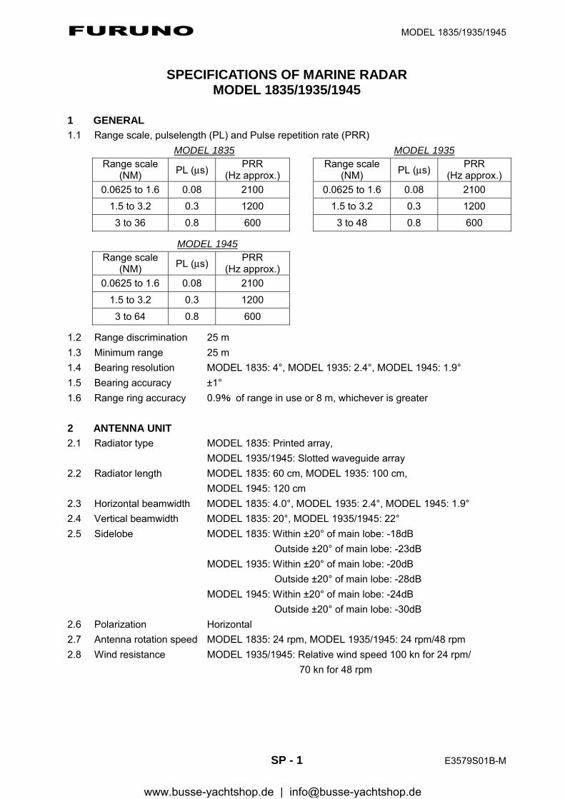
FURUNO MODEL 1835/1935/1945
SP - 1 E3579S01B-M
SPECIFICATIONS OF MARINE RADAR MODEL 1835/1935/1945
1 GENERAL 1.1 Range scale, pulselength (PL) and Pulse repetition rate (PRR)
MODEL 1835 MODEL 1935 Range scale
(NM) PL (μs) PRR (Hz approx.)
Range scale (NM) PL (μs) PRR
(Hz approx.) 0.0625 to 1.6 0.08 2100 0.0625 to 1.6 0.08 2100
1.5 to 3.2 0.3 1200 1.5 to 3.2 0.3 1200 3 to 36 0.8 600
3 to 48 0.8 600 MODEL 1945
Range scale (NM) PL (μs) PRR
(Hz approx.) 0.0625 to 1.6 0.08 2100
1.5 to 3.2 0.3 1200 3 to 64 0.8 600
1.2 Range discrimination 25 m 1.3 Minimum range 25 m 1.4 Bearing resolution MODEL 1835: 4°, MODEL 1935: 2.4°, MODEL 1945: 1.9° 1.5 Bearing accuracy ±1° 1.6 Range ring accuracy 0.9% of range in use or 8 m, whichever is greater 2 ANTENNA UNIT 2.1 Radiator type MODEL 1835: Printed array, MODEL 1935/1945: Slotted waveguide array 2.2 Radiator length MODEL 1835: 60 cm, MODEL 1935: 100 cm, MODEL 1945: 120 cm 2.3 Horizontal beamwidth MODEL 1835: 4.0°, MODEL 1935: 2.4°, MODEL 1945: 1.9° 2.4 Vertical beamwidth MODEL 1835: 20°, MODEL 1935/1945: 22° 2.5 Sidelobe MODEL 1835: Within ±20° of main lobe: -18dB
Outside ±20° of main lobe: -23dB MODEL 1935: Within ±20° of main lobe: -20dB Outside ±20° of main lobe: -28dB MODEL 1945: Within ±20° of main lobe: -24dB Outside ±20° of main lobe: -30dB 2.6 Polarization Horizontal 2.7 Antenna rotation speed MODEL 1835: 24 rpm, MODEL 1935/1945: 24 rpm/48 rpm 2.8 Wind resistance MODEL 1935/1945: Relative wind speed 100 kn for 24 rpm/ 70 kn for 48 rpm
www.busse-yachtshop.de | [email protected]
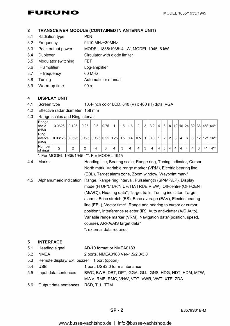
FURUNO MODEL 1835/1935/1945
SP - 2 E3579S01B-M
3 TRANSCEIVER MODULE (CONTAINED IN ANTENNA UNIT) 3.1 Radiation type P0N 3.2 Frequency 9410 MHz±30MHz 3.3 Peak output power MODEL 1835/1935: 4 kW, MODEL 1945: 6 kW 3.4 Duplexer Circulator with diode limiter 3.5 Modulator switching FET 3.6 IF amplifier Log-amplifier 3.7 IF frequency 60 MHz 3.8 Tuning Automatic or manual 3.9 Warm-up time 90 s 4 DISPLAY UNIT 4.1 Screen type 10.4-inch color LCD, 640 (V) x 480 (H) dots, VGA 4.2 Effective radar diameter 158 mm 4.3 Range scales and Ring interval
Range scale (NM)
0.0625 0.125 0.25 0.5 0.75 1 1.5 1.6 2 3 3.2 4 6 8 12 16 24 32 36 48* 64**
Ring interval (NM)
0.03125 0.0625 0.125 0.125 0.25 0.25 0.5 0.4 0.5 1 0.8 1 2 2 3 4 6 8 12 12* 16**
Number of rings 2 2 2 4 3 4 3 4 4 3 4 4 3 4 4 4 4 4 3 4* 4**
*: For MODEL 1935/1945, **: For MODEL 1945 4.4 Marks Heading line, Bearing scale, Range ring, Tuning indicator, Cursor,
North mark, Variable range marker (VRM), Electric bearing line (EBL), Target alarm zone, Zoom window, Waypoint mark*
4.5 Alphanumeric indication Range, Range ring interval, Pulselength (SP/MP/LP), Display mode (H UP/C UP/N UP/TM/TRUE VIEW), Off-centre (OFFCENT (M/A/C)), Heading data*, Target trails, Tuning indicator, Target alarms, Echo stretch (ES), Echo average (EAV), Electric bearing line (EBL), Vector time*, Range and bearing to cursor or cursor position*, Interference rejecter (IR), Auto anti-clutter (A/C Auto), Variable range marker (VRM), Navigation data*(position, speed, course), ARPA/AIS target data* *: external data required
5 INTERFACE 5.1 Heading signal AD-10 format or NMEA0183 5.2 NMEA 2 ports, NMEA0183 Ver-1.5/2.0/3.0 5.3 Remote display/ Ext. buzzer 1 port (option) 5.4 USB 1 port, USB2.0 for maintenance 5.5 Input data sentences BWC, BWR, DBT, DPT, GGA, GLL, GNS, HDG, HDT, HDM, MTW,
MWV, RMB, RMC, VHW, VTG, VWR, VWT, XTE, ZDA 5.6 Output data sentences RSD, TLL, TTM
www.busse-yachtshop.de | [email protected]
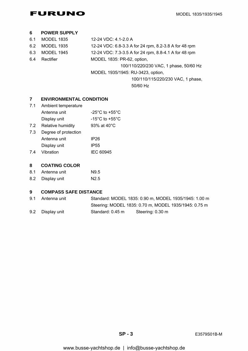
FURUNO MODEL 1835/1935/1945
SP - 3 E3579S01B-M
6 POWER SUPPLY 6.1 MODEL 1835 12-24 VDC: 4.1-2.0 A 6.2 MODEL 1935 12-24 VDC: 6.8-3.3 A for 24 rpm, 8.2-3.8 A for 48 rpm 6.3 MODEL 1945 12-24 VDC: 7.3-3.5 A for 24 rpm, 8.8-4.1 A for 48 rpm 6.4 Rectifier MODEL 1835: PR-62, option, 100/110/220/230 VAC, 1 phase, 50/60 Hz MODEL 1935/1945: RU-3423, option, 100/110/115/220/230 VAC, 1 phase, 50/60 Hz 7 ENVIRONMENTAL CONDITION 7.1 Ambient temperature
Antenna unit -25°C to +55°C Display unit -15°C to +55°C
7.2 Relative humidity 93% at 40°C 7.3 Degree of protection
Antenna unit IP26 Display unit IP55
7.4 Vibration IEC 60945 8 COATING COLOR 8.1 Antenna unit N9.5 8.2 Display unit N2.5 9 COMPASS SAFE DISTANCE 9.1 Antenna unit Standard: MODEL 1835: 0.90 m, MODEL 1935/1945: 1.00 m Steering: MODEL 1835: 0.70 m, MODEL 1935/1945: 0.75 m 9.2 Display unit Standard: 0.45 m Steering: 0.30 m
www.busse-yachtshop.de | [email protected]
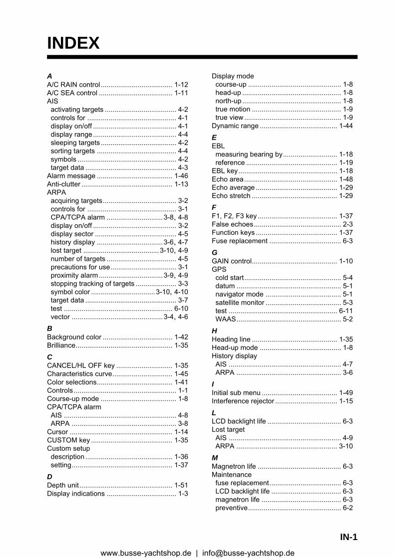
INDEX
AA/C RAIN control..................................... 1-12A/C SEA control ...................................... 1-11AISactivating targets ..................................... 4-2controls for .............................................. 4-1display on/off ........................................... 4-1display range........................................... 4-4sleeping targets ....................................... 4-2sorting targets ......................................... 4-4symbols ................................................... 4-2target data ............................................... 4-3
Alarm message ....................................... 1-46Anti-clutter ............................................... 1-13ARPAacquiring targets...................................... 3-2controls for .............................................. 3-1CPA/TCPA alarm .............................3-8, 4-8display on/off ........................................... 3-2display sector .......................................... 4-5history display ..................................3-6, 4-7lost target ....................................... 3-10, 4-9number of targets .................................... 4-5precautions for use.................................. 3-1proximity alarm.................................3-9, 4-9stopping tracking of targets ..................... 3-3symbol color .................................3-10, 4-10target data ............................................... 3-7test ........................................................ 6-10vector ............................................... 3-4, 4-6
BBackground color .................................... 1-42Brilliance.................................................. 1-35
CCANCEL/HL OFF key ............................. 1-35Characteristics curve............................... 1-45Color selections....................................... 1-41Controls..................................................... 1-1Course-up mode ....................................... 1-8CPA/TCPA alarmAIS .......................................................... 4-8ARPA ...................................................... 3-8
Cursor ..................................................... 1-14CUSTOM key .......................................... 1-35Custom setupdescription ............................................. 1-36setting.................................................... 1-37
DDepth unit................................................ 1-51Display indications .................................... 1-3
Display modecourse-up ................................................ 1-8head-up ................................................... 1-8north-up ................................................... 1-8true motion .............................................. 1-9true view.................................................. 1-9
Dynamic range ........................................ 1-44
EEBLmeasuring bearing by............................ 1-18reference ............................................... 1-19
EBL key................................................... 1-18Echo area................................................ 1-48Echo average .......................................... 1-29Echo stretch ............................................ 1-29
FF1, F2, F3 key ......................................... 1-37False echoes............................................. 2-3Function keys .......................................... 1-37Fuse replacement ..................................... 6-3
GGAIN control............................................ 1-10GPScold start.................................................. 5-4datum ...................................................... 5-1navigator mode ....................................... 5-1satellite monitor ....................................... 5-3test ........................................................ 6-11WAAS...................................................... 5-2
HHeading line ............................................ 1-35Head-up mode .......................................... 1-8History displayAIS .......................................................... 4-7ARPA ...................................................... 3-6
IInitial sub menu ....................................... 1-49Interference rejector ................................ 1-15
LLCD backlight life ...................................... 6-3Lost targetAIS .......................................................... 4-9ARPA .................................................... 3-10
MMagnetron life ........................................... 6-3Maintenancefuse replacement..................................... 6-3LCD backlight life .................................... 6-3magnetron life ......................................... 6-3preventive................................................ 6-2
IN-1www.busse-yachtshop.de | [email protected]
INDEX
Menu ..........................................................1-4MENU key..................................................1-4Multiple echoes ..........................................2-3
NNavigation dataat screen bottom ....................................1-43stand-by .................................................1-43
Noise rejector ...........................................1-38North-up mode ...........................................1-8
OOFF CENTER key ...................................1-25Off-centering the display ..........................1-25
PPOWER/BRILL key............................ 1-2, 1-4Proximity alarmAIS ...........................................................4-9ARPA .......................................................3-9
Pulselength ..............................................1-20
QQuick start ..................................................1-2
RRACON ......................................................2-8Range and bearing between two targets .1-19RANGE key..............................................1-10Range measurement ...............................1-16Range preset ...........................................1-49Range ring brilliance ................................1-16Range unit................................................1-51Remote display ........................................1-56
SSART .........................................................2-6Second-trace echoes ...............................1-39Sector blank .............................................1-52Shadow sector ...........................................2-5Ship speed unit ........................................1-51Sidelobe echoes ........................................2-4STBY/TX key .............................................1-2System configuration .................................. xii
TTarget alarmalarm type ..............................................1-23deactivating .................................. 1-23, 1-24setting.....................................................1-22stopping..................................................1-22strength level..........................................1-24
TARGET ALARM key ..............................1-22Target trailscolor .......................................................1-32gradation ................................................1-32level........................................................1-33mode ......................................................1-31narrow trails............................................1-34restarting ................................................1-33starting ...................................................1-31stopping..................................................1-31
trail copy.................................................1-33your ship trail..........................................1-34
Temperature unit......................................1-51TestARPA .....................................................6-10diagnostic .................................................6-7GPS........................................................6-11LCD..........................................................6-9
TLL key ....................................................1-34TRAILS key..............................................1-31Troubleshootingadvanced-level .........................................6-5simple.......................................................6-4
True motion mode......................................1-9True view mode..........................................1-9Tuning ........................................................1-6
VVirtual image ..............................................2-4VRMmeasuring range by ...............................1-17unit of range measurement ....................1-17
VRM key ..................................................1-17
WWatchman................................................1-40Waypoint marker ......................................1-46Wind direction ..........................................1-51Wind speed unit .......................................1-51Wiper........................................................1-39
ZZoom........................................................1-27
IN-2www.busse-yachtshop.de | [email protected]