maritime (fiji small craft code) regulations 2014extwprlegs1.fao.org/docs/pdf/fij152582.pdf ·...
TRANSCRIPT

828
[LEGAL NcmeE No. 1041
MARITIME TRANSPORT DECREE 2013 (DECREE No. 20 OF 2013)
Maritime (Fiji Small Craft Code) Regulations 2014 IN exercise of the powers conferred upon me by section 240(b), (c) and (f) of the Maritime Transport Decree 2013, 1 hereby make these Rcglliations~
Shortlille alit! COJIIII/CI/{'CIIlCIlI
1. These Regulations may he cited as the ~\'laritime (Fiji Small Craft Code) Regulations 2014 and shall come into force on a date appointed by the Minister in the Gazette.
interpretation
2. In these Regulations, unless the context otherwise rcquires-
"act:ommodation space" means passenger spaces, corridors, lavatories, cabins, offices, crew spaces, shops, bond stores, isolated pantries and lockers and similar spaces;
"Administration" means the Government of the State under whose authority a ship is operating and whose Ilag the ship is entitled to fly;
"approved" means approved by the Chief Executive Officer;
"approved servicing centre" means in relation to inflatable life rafts, inllatable lifejackets, inllatcd rescue boats and hydrostatic release units, a facility for servicing inflatable life rafts and inflatable lifejackets that has been approved for that purpose by the Chief Executive Officer and approved in writing by the l11aIluhlcturer of the inflatable life rafts and inftatnblc lifejacket as a servicing centre for that product;
"authorised" means authorised by the Chief Executive Officer;
"authorised officer" has the same meaning under section 2 of the Decree;
"Recognised Organisation" means an organisation which has entered into a memorandum of agreement with the Chief Execlltive Officer in compliance with the IMOAssembly Resolution A.739 (IS) and theAnnexes as amended by Resolution MSC 20S(gl) thereto entitled Adoptioll oj Amendmellts to the Guide/jlll!s for the Authorization of Orgallisatiolls acting Oil behalf of the Administmtioll, governing the undertaking of particular survey and certification fUllctions by the organization's employees under the Decree and the Ivtaritime and rvtarine Environment Protection Regulations. These recognized organisations include classification societies which are periodically audited and given instructions by the Authority for the purpose of survey, audit and certification;
"Authority" means the ivlaritime Safely Authority of Fiji unless stated otherwise in the text;

829
"breadth" mealls the maximulll breadth measured in metres amidships-
(a) in the case of a metal hllll~ to the moulded line of the frame; and
(b) in the case of any other hull- to the ouler surface of the hull;
"cargo space" means all spaces appropriated for cargo including trunks leading to such spaces;
"Chief Executive Officer" means the Chief Executive Officer of the Authority;
"Classification Society" means a recognised organisation authorized by the Chief Executive Officer to conduct slich inspections and stich audits as the Authority considers necessary for the purposes of these Regulations;
"Coasting-trade Licence" llleallS the license defined under section 110 of the Decree, authorising a ship to engage in trade in a particular area slating the total allowable number of passengers, type of cargo and crew the ship may carry;
"Code" means the Fiji Small Craft Code annexed as a Schedule to these Rcgulations.;
"commercial ship" has the same meaning under section 2 of the Decree;
"crew accolllillodation" or "Crew Space" means such parts of the ship sel aside for the exclusive use of the Crew;
"Decree" means the Maritime Transport Decrec 20 I J;
"depth" means the moulded depth measured in metres at mid length from the base line to the top of the freeboard deck beams at the side of the ship or, in the case of all open and well~deck ships, to the top of the gUl1whale. For thc purposes of this definition, the base line is the line projected by the plane forming the top of the keel where a plate keel is fitted. In the case of a timbcr or com""posite ship, thc top of the keel shall be read as a reference to the lower edge of the keel rabbet. In the case of a ship which has a bar keel or in which the form at the lower part or the midship section is of a hollow character, or thick garboards arc titted, thc top of the keel shall be read as a reference to the point where the flat of the bottom continued inward cuts the side of the keel of the ship. In each case the plane shall be horizontal when extended transversely;
"Enforcement and Compliance Officer" means the person or persons to whom thc Chief Exccutive Of/iceI' has delegated the powers for entry and clearance of ships and to inspect and verify compliance or the condition of a ship's loading, manning, survey certificates, and other statutory ship's documentation prior to departure or on arrival of the ships at the port or at any place out at sea;
"Fiji Trade" or "Territorial waters voyage" means a voyage, trade or operation of a ship from a port or place in Fiji for more than 15 nautical miles to another port or place in Fiji that is within the archipelagic waters and territorial waters of Fiji;

830
"nshing ship" has the same meaning under section 2 of the Decree;
"Inland waters voyage" means a voyage, trade or operation of a ship within the inlnnd waters of Fiji which include rivers. lakes anti dams which terminates at the shoreline of any island of Fiji;
"Inshore \Vater Voyage" means a voyage, trade or operation of a vessel of not mOfe than IS nautical miles from a port or place in Fiji to another port or place in Fiji within the archipelagic waters of Fiji;
"Interim Survey Certificate" means the maritime document issued by the Chief Executive Officer for the purpose of allowing the ship to travel on that voyage period of not more than two weeks. An Interim Survey Certificate is issued only when the survey report is still in the process of completion but then the delay in the completion of such a report subsequently delays a ship's outward clearance;
"length" or "measured length" in accordance with paragraph 1 of the Fiji Maritime Code lneans-
(a) the distance from the fore part of the hull to the after part of the hull or transom taken at the upper side of the uppermost weathertight deck; or
(b) in the case of open ships, at the height of the gUllwhale, the protrusion of a stem post or stempost is not included in this measurement;
"lifesaving appliances" means any device, arrangement, apparatus or thing intended to sustain the lives of people in distress, or to signal their distress, or to alert people on-board a ship to an emergency, and includes lifebuoys, lifejackcts, immersion suits, nnti-exposure suits, visual signals, survival craft, rescue boats. evacuation systems, line-throwing appliances, and general alarm and public address systems;
"lifesaving equipment" means equipment stored in or belonging to a lifesaving appliance and required to be carried on-board a ship;
"j\ifaster" has the same meaning under section 2 of the Decree;
"Nautical Mile" means the International nautical mile of 1852 metres;
"open ship" means a ship which has no weather tight deck for the whole or part of the length of the ship e.g. a rowing boat with open bottom boards or a half cabin ship with a cockpit aft Htted with loose deck panels;
"owllcr"-
(a) in relation to a ship registered in Fiji under the Ship Registration Decree 2013, means the registered owner of the ship;
(lJ) in relation to a ship registered in any place outside Fiji. means the registered owner of the ship;

83/
(c) in relation to a Ilshing ship, other than one to which paragraph (a) or (b) applies, means the person registered as the owner under section 6 of the Offshore Fisheries i'Vlanagemenl Decree 2013;
(d) in relation to a ship to which paragraph (a), (h) or (e) applies, where, by virtue of any charter or demise or for any other reason, the registered owner is not responsible for the management of the ship, includes the charterer or other person who is for the time being so responsible; or
(e) in relation to an unregistered ship or a registered ship that does not have a registered owner, means the person who is [or the time being responsible for the management of the ship;
"passenger" has the same meaning as that in section 2 of the Decree;
"passenger ship" means a ship engaged in domestic or international voyages which carry more than 1 welve passengers;
"Radio Surveyor" means a person appointed as such by the Chief Executive Officer;
"Sanitary (fumigation) Certificate" is a certificate issued by the Port Health Authorities certifying that the ship is compliant with Health Regulations. The certificate is valid for six months and renewable half yearly;
"sheltered waters voyage" means a limited voyage, trade or operation of a ship within protected waters adjacent to beaches or landings within Fiji;
"ship" has the same meaning under section 2 of the Decree;
"Shipping Officer" means the person or persons to whom the Registrar has delegated the powers of dealing with the engagement and discharge of crew (crew agreement), verification of crew listing, registration of ships and other matters pertaining to the legal requirements of operating trading ships;
"SOL,AS" in respect of an item or appliance means that the item or appliance shall comply with the requirements of the SOlAS Convention, taking into account the date on which the ship's keel was laid or was at a similar stage of construction;
"standards abbreviations" means-
(a) A.S refers to the Australian Standard;
(b) ASTM refers to the American Standard for Testing iVlaterials; and
(e) AlPGA refers to the Australian Liquidified Petroleum Gas Association.
"superstructure" means a decked structure, including a raised quarter deck, on the freeboard dcck extending from side to side of the ship or with the side plating of the stmcture not being inboard of the shell plating by Illore than

832
4 per cent of the breadth of the ship. \Vhere, in pursuance of the above, a lower deck is speciHeci as the freeboard deck of a ship, any part of the hull which extends above the deck so specified shall be cieemed to be a superstructure;
"Surveyor" means a person from the Authority or recognised organizations that holds the prescribed maritime doculllents issued in accordance with section 24 of the Decree certifying them to provide the tests, inspections or the survey, audit, or certification of ships, maritime equipment or products;
"Survey Certificate" is a maritime doculllclll issued subsequent to an inspection or survey by a Surveyor. The survey certificate details the Safety equipment which the ship carries, and the particular area in which the ship may trade, and any restrictions which the Chief Executive Officer deems necessary to impose due to the condition of the ship or its equipment; and
"tonnage" means the gross tonnage of the ship.
Pllrpose
3. The purpose of these Regulations is to give legal effect to the Fiji Small Craft Code set out in the Schedule which detait" the standards and requirements relating to commercial ships of 15 metres or less in registered length.
FYi SlIIall Craft Code .liil·clI/orcc (d hI\\'
4.-(1) The Code shall have force of law in Fiji.
(2) This Code has effect except to the extent where there is any inconsistency between this Code and any provision of the Decree, the Decree shall prevail.
Applh'miOl/
5. These regulations apply to ships of 15 metres or less in registered length operating within Fiji waters; and, in respect of the construction, survey and safe operation of ships of this type the Chiel'Execlitive OHker shall be guided by the requirements and standards of the Code set out in the Schedule to these Regulations.
Ships to bc properly III(III/Jcd
6.-(1) Subject to sub-regulation(3), neither the owner nor the master of a ship of 15 mctres or less in registered length shall send or take the ship to sea or permit the ship to remain at sea with fewer qualil1ed seaL1rers on board than the complement prescribed in respect of that ship by paragraph 3 of the Schedule.
(2) Any owner or master who fails to comply with sub-regulation (I) cOlllmits an offence and is liable upon conviction to a fine not exceeding $2,000 or imprisonment of lip to 3 months, or to both.
(3) \Vhere a ship to which sub-regulation (I) applies, is at a port or placc and does not have on bO<lrd the prescribed number of seat~lfers of a particular class, the Chief Executive Officer may, where he or she is satisfied that-
(a) a qualified seat~1rer or that class is not available for employment at that port or place;

833
(h) it would be unreasonable to require the owner or master to obtain a qualified 'seafarer of that class from another port or place; and
(c) the safety of the ship would not be endangered,
allow the ship, subject to any conditions he or she thinks fit, to go to sea without carrying the prescribed complement of seafarer of that class.
(4) Where this regulation applies in respect of a ship, the master and the owner of the ship shall each take such action as maybe necessary to ensure that any conditions imposed under sub-regulation (3) arc observed.
(5) Any owner or master who hlils to comply with sub-regulation (3) commits an offence and is liable upon conviction to a fine not exceeding $2,000 or imprisonment of up to 3 month, or to both.
Ship,\ 10 be .\IIn'eyed
7. Ships of 15 metres or less in register length shall undergo the surveys and inspections prescribed in the Schedule.
Prilldplt's 10 he followed ill carryillg Olll .wrwys
8. In carrying out a survcy, a surveyor shall be guided, as appropriate, by-
(a) paragraph 5 - Construction;
Ihi paragraph 6 - Loadlines;
1(') paragraph 7 - Stability;
(d) paragraph 8 - Engineering;
(e) paragraph 9 - Lifesaving appliances and equipment;
(I) paragraph 10 - Radio equipment;
(g) paragraph 11 - Navigation and miscellaneous equipment;
(Il) paragraph 12 - Survey and Certil1cates of Survey;
(i) paragraph 13 - Emergency procedures and Safety of Navigation;
(j) paragraph 14 - Collision Regulation- Local Harbour Regulation; and
(k) paragraph is - Lifesaving appliances and equipment requircments,
of the Schedule.
Requirelllellt to {'mry certain sofi'!.\' {'qllipllli'nt
9,-(1) The owner and the master of a ship IS metres or less in registered length shall each ensure-
(a) that there is carried on or fitted in the ship the safety equipment specified in respect of the ship under paragraph 15 of the Schedule as applicable, with any standard applicable to the equipment specified in paragraph 9 of lhe Schedule; and

834
(b) that there is carried on or fitted in the ship the Navigation and miscellaneous equipment specified in respect orthe ship by paragraph 11 of the Schedule; and
(e) that the safety equipment, navigation and miscellaneous equipment filted or carried in accordance with paragraph (a) and (b) is in good order and ready for lise, before the ship goes to sea.
(2) Any owner or master of a ship who fails to comply with this Regulation commits an offence and is liable upon conviction to a tine not exceeding $2,000 or imprisonment of up to 3 months, or to both.
Master to ('O/I/ply wilh certain pn)l'isiollS of lite Schedule
10.-(1) The master of a ship Ie'S than 15 metres in registered length shall comply with the following provisions of the Schedule-
(a) paragraph 4.13 and 4.14 - documents to be produced before clearance outwards;
(b) paragraph 4.15 - documents to be delivered and reports to be made when entering inwards;
Ie) paragraph 11.2.6 - Ship Record Book to be kept and produced;
(d) paragraph 12 - damage to ship to be reported and special survey to be called for;
(e) paragraph 13 - crew to be informed of emergency station duties; and
(j) parapgrah 14 - obligation to comply with Collision Convention.
(2) Any master of a ship who fails to comply with this regulation commits an offence and is liable upon conviction to a fine not exceeding $2,000 or imprisonment of up to 3 months, or to both.
Repeal
II. The Marine (Fiji Small Craft Code) Regulations 1990 arc hereby repealed.
Made this 14th day o[December 2014.
P. TIKODUAUDA Minister for Infrastructure and Transport

835
SCHEDULE
FIJI SMALL CRAFT CODE (Regulariou 4)
(Ships of 15 metres or less in registered length)
TABLE OF CONTENTS
PARAGRAPHS
Introduction 2 Examinations for boat masters, restricted and full Class 6 Masters/ Engineer
Licences 3 Sate 1\1anning 4 Shipping Office 5 Construction 6 Loadlincs 7 Stability 8 Enginecling 9 Lifesaving appliances and equipment standards
10 Radio Equipment II Navigation and Miscellaneous equipment 12 Surveys and Certificates of Survey 13 Emergency procedures and Safety of Navigation 14 Collision Regulations - Local Harbour Regulations 15 Lifesaving appliances and equipment requirements 16 Ships bunkering operations requirements
PARAGRAPH 1
1. 0 INTRODUCTION
1.1 Ships of 15 metres or less in register length shaH be allocated a tonnage where the ship owner or operator so requests, in respect of regulations, laws or other requirements which normally apply to a ship in terms of its tonnage.
1.2 The Chief Executive Officer may, subject to the principles embodied in these requirements, exempt a ship, or ships included in a specified class of ship, from the application of any of the provisions of these requirements to the extent that the Chief Executive Officer is satisfied that the criteria under section 33 of the Decree has been met.
1.3 Where in the case of a ship provlsIOn is not made in these requirements to cover a specific matter, the Chief Executive Officer may determine what special provisions shall apply to that matter.

836
PARAGRAPH 2
2.U EXAMINATIONS FOR BOAT MASTERS, RESTRICTED AND FULL CLASS 6 MASTERIENGINEER LICENCES
2.1 A Boat Master Licence, Master Class 6 (Restricted or Full) Certificate are documents permitting the holder to take overall charge of a ship within the operating limits and under the Special Conditions stated on the licence.
2.2 The Boat Master Licence, Master Class 6 (Restricted or Full) Certificate is not to be used for the manning of all ships operating beyond the Fiji Trade Area.
2.3 The Boat Master License may be endorsed with the discretion of the Chief Executive Officer to allow the holder of the licence to operate olltside any infringing reefs to not more than 500 meters.
2.4 The licence wiB contain the following informatiol1-
(aJ name of the holder and Humber of licence and date of issue;
(b) area of operation-
(i) a specific Sheltercd water area; or
(ii) a specific Inshore water area; or
(iii) Fiji Trade area (Territorial Waters Voyage);
(e) the signature and offlcial stalllP of the Chief Executive Officer;
(d) the Class 6 Master Enginecr (Restricted or Full) licence Illay only be held by Fiji nationals, or persons currently holding a valid work permit for Fiji employment; and
(e) all pleasure craft operators shall hold the Boat i'Vlasters Licence,
2.5 Requirements for candidates for a Boat Master's L·icence are-
(a) Minimum age 16 years;(b) 3 Months sea-service in a deck capacity, This service shall have been performed in the type of ship for which the licence will be granted;
(e) In the case of yachts, the candidate Illay be permitted to include amateur service so long as it call be verified to the satisfaction of the Chief Execlltive Officer and is relevant to the type of service for which the licence is being issued. Holders of British Royal Yachting Association or U.S. Coast Guard amateur qualifications or equivalent qualification recognised by the Authority maybe issued with an equivalent licence without further examination at the Chief Executive Officer's discretion;
(d) Pass a medical examination by a registered medical practitioner approved by the Chief Executive Officer; and
(e) Pass an examination based on the syllabus specified in Appendix I to this paragraph.

837
2.6 The Boat Master certificate is a licence permitting the holder to sail as a person in charge of the ship of 20 gross tonnage or less engaged on sheltered waters voyage.
2.7 The Class 6 Master/Engineer (Restricted) certificate is 11 licence permitting the holder to sail as a person in charge of the ship of20 gross tonnage or less engaged on inshore voyage.
2.8 Requirements for candidates for a Class 6 Master/ Engineer (Restricted) licence are~
(a) Minimum Age 18 years;
(/J) At least 6 months sea-going service experience in the deck and engine Departments or if holding a boat master's licence, at least 3 months seagoing service experience in the deck and engine department;
(c) Pass a medical examination by a registered medical practitioner approved by the Chief Executive Officer; and
(d) Pass an examination based on AppendL"\ I to this paragraph.
2.9 The Class 6 Master !Engineer (Full) certificate is a licence pennilting thc holder to sail as a person in charge of ships of 20 gross tonnage or less engaged on Fiji trade or territorial water voyages.
2,10 Requirements for candidates for a Class 6 Master/ Enginecr (Full) licence are
(0) MinimumAgc 18 years;
(b) At least 12 months sea-going service experience in the deck and engine departments;
(c) Pass a mcdical examination by a registered medical practitioncr approved by the Chief Executive Officer;
(d) (Pass an eyesight test by a registered medical optometrist. (Requires discretion of the Chief Executive Officer);
Ie) Hold a Global Maritime Distress Safety System - Restricted Operators Certificate (GMDSS-ROC);and
(n Pass an examination based on Appendix I to this paragraph.
2.11 The Chief Executive Officer may approve employees of the Authority to conduct Boat Masters, Restricted 01' Full Class 6 Mastel1Engineer training as part of the maritime awarencss program if the current approved maritime training institutions do not have the capacity to deliver such courses to meet the demand from the maritime sector. Government may need to subsidise the Authority or the Authority will prescribe appropriate fees to cover the training expenses.

838
APPENDIX I
EXAMINATION SYLLABUS
BOAT MASTER'S LICENSE-SHELTERED WATERS VOYAGE
The examination shall comprise of oral questions using instruments and models as applicable and a practical demonstration of ability aboard a ship in the applicable harbour or river and shall cover the following areas-
(a) handling power boals, effect of propeller on steering the boat. Berthing, unberthing alongside and stern to whatf. Effect of wind (and current if applicable). Turning short round. Securing to buoy. Anchoring. Man overboard;
(b) use and maintenance of statutory lifesaving and firefighting appliances;
(e) a working knowledge of thc Harbour Regulations and Marine Regulations applicable to the Harbour or river, and type of craft;
(d) the ability to steer by compass. Sitting a compass on a small craft;
(e) a working knowledge of the Collision Regulations, Steering and Sailing Rules; recognition of the lights for a power, sailing and towing vessel. Recognition of the sound signals for vessels maneuvering;
(jj working knowledge of maritime navigation safety regulation;
(g) recognition of hurricane warnings both visual and by radio;
(11) action to be taken;
(i) a knowledge of the harbour lights, beacons, dangers, prohibited anchorages and generallopography applicable to the particular harbour or river;
(j) a working knowledge of marine engines and bilge pumps for small crafts;
(k) safe handling of fuels and gas used in small craft; and
(I) duties to other vessels and personnel in relation to Collision or distress.
The examination shall also comprise the following with emphasis on the practical application of the necessary Knowledge-
(a) Outboard motor operation;
(b) Principles of operation;
(e) Fuel system (portable and fixed);
(d) Cooling system;
(e) lnlcrnallubrication;
(t) Starting procedure;
(x) Outboard Motor Trouble shooting and maintenance if-
(i) Engine fails to start;

839
(ii) Engine overheats;
(iii) Electrical fault;
(iv) Engine has been submerged;
(v) Care and charging of batteries, fuses; and
(vi) Gearbox, propellers, batteries, etc.
RESTRICTED MASTERlENGlNEER LICENCES-INSHORE VOYAGE
The examination will include questions and demonstrations as for boat master's license, for sheltered waters, and, in addition the following areas-
(a) a practical voyage over part or a11 of the particular passage to which the licence would apply;
(b) knowledge of any Maritime regulations of Marine districts through which the route lies;
(c) use of a chart to identify beacons, dangers, prohibited anchorages. general topography, reef passages and sheltered anchorages along the route;
(d) use of a chart to select magnetic course;
(e) recognition of lights and shapes shown by vessels fishing, not-ulldercommand, and engaged in underwater operations;
Ij) a working knowledge of sOllnd signals in restricted Visibility;
(g) a working knowledge of trim, stability and risk of slack water in bilges;
(11) passenger and Cargo documentation;
(i) the Master's liability in carriage of passengers and cargo;
(j) lise and recognition of distress sigllals;
(k) action on ground; and
(I) lise of hand lead.
The examination shall also include the following with emphasis on the practical application of the necessary knowledge-
(a) Engineering knowledge - oral and practical;
(b) The working of internal combustion and compression ignition engines on diesel engines;
(c) Engine maintenance;
(d) Two stroke and four stroke cycles;
(e) Circulation systems;
Ij) Lubrication systems;
(g) Care and changing of injectors;
(h) Care and charging of batteries and fuses;

(i) Maintenance when on slip;
(j) Outboard motor operation;
(k) Principles of operation
840
(I) Fuel system (portable and fixed);
(m) Cooling system;
(11) Internal lubrication;
(0) Starting procedure;
(p) Outboard Motor Trouble shooting and maintenance if-
(i) Engine fails to start;
(ii) Engine overheats;
(iii) Electrical fault;
(iv) Engine has been submergcd~ and
(v) Gearbox, propellers, batteries, etc.
FULL CLASS 6 MASTER/ENGINEER CERTIFICATE: FIJI TRADE
The examination will include questions and demonstrations as for Restricted Class 6 license ~
Inshore voyage, and in addition, the folJowing-
(a) The practical voyage need not apply to the passages beyond the shelter of the reef;
(b) The oral will include a full working knowledge of the Collision Regulations; action in heavy weather, use of sea anchor, collision; a working knowledge of local search and rescue procedures; recognition of visual signs of a tropical cyclone; recognition of the more important International Code flags and their single letter meanings; and including radio communication procedures;
(c) A (2 hour) written paper on chart work and pilotage based 011 the largest scale chart covering the entire passage to which the licence would apply as folloll's-
(i) Given variation as per chart, and a deviation card, to convert true courses to compass courses and vice versa;
(ii) To find the True aud compass courses between two positions without allowance for current or leeway. Calculation of speed, distance to Hln and estimated time of arrival;
(iii) Fixing position on chart by cross bearings;
(iv) A non-Mathematical appreciation of the effect of the prevailing currents and tides in the locality and the effects of leeway; and
(v) Recognising the more relevant chart symbols.
841
(d) Assessment on setting up and operating radar sets for navigation, collision avoidance and application of the International Regulations of Prevention of Collision at Sea on small vessels-
(i) Describe how a slllall ship's radar works;
(ii) Describe the factors that affect detection and presentation of a target on a radar display;
(iii) Set up ami maintain the picture on a radar set of the type installed on small vessels;
(iv) Interpret the radar display;
(v) Use a radar set as an aid to navigation;
(vi) Apply the information obtained from radar to aid in avoiding collision; and
(vii) Basic Operational knowledge of lIsing GPS - limitations.
(e) Assessment (written or oral) will be based on the-
(i) use correct radiotelephone operating procedures particularly those relating to distress, urgency and safety messages;
(ii) operate thc controls of marine radio equipment to ensure maximum Performance;
(iii) conduct routine maintcnance required to keep radio equipment in good working order and to repair simple faults;
(iv) operate radio equipment in accordance with regulations applicable to radiotelephone ship stations.
ENGINEERING KNOWLEDGE
The examination (written and oral) shall comprise the following with emphasis on the practical application of the necessary Knowledge-
(a) Engineering Knowledge - Written/Oral and Practical:
(i) Dcseribe the operating principles of marine diesel engines and recognise major components and describe their function;
(ii) Start up, shut down and monitor the operation of marine diesel engines and recognise common defects;
(iii) Operate marine outboard engines, recognise comlllon defects and carry out user maintenance;
(iv) Operale and maintain a reverselreduction gearbox and shafting;
(v) Operate and maintain the vessel's hydraulic systems and steering gear;
(vi) Operate the bilge pumping and deck wash systems, recognise faults, and carry oul regular maintenance;

842
(vii) rvlanagc a low voltage DC battery system in accordance with safe and statutory requirements;
(viii) Operate and maintain the vessel's deck machinery in accordance with safe and established procedures;
(ix) Operate and maintain the tire fighting and safety equipment and conduct on board inspection to maintain their survey requirements in accordance with established emergency procedures;
(x) Determine the consumption of fuel and lubricating oil for a voyage in accordance with established procedures and safe practices;
(xi) Manage the engineering duties on board a vessel during docking operations in accordance with safe and established procedures; and
(xii) Operate and maintain the vessel's deck machinery in accordance with safe and established procedures.
SAILING SHIPS LICENCE: SAIL ENDORSEMENT
The sailing endorsement applies to the holder of a Sailing licence in either of the other categories according to the service in which the ship will serve and will in addition be examined as follows-
(a) Oral knowledge of the collision regulations particularly referring to ships under sail (whether or not under power);
(h) English names of parts of sails, standing and running rigging, nautical terms used in tacking and jibbing;
(c) Use of lifelines and safety harness;
(d) Organisation of crew into manoeuvring stations;
(e) Reefing at sea,Choice of sails;
U) Heaving to under sail;
(g) Use of sea anchor in heavy weather;
(II) Man-overboard under sail;
(0 A practical voyage under sail during which the candidate will demonstrate his skill, in and ability to communicate orders for-
(i) tacking, jibbing, reefing, changing sail, heaving to, picking up a man overboard undcr sail, bcrthing under sail; and
(ii) instructing passengers in safety drills.
PARAGRAPH 3
SAFE MANNING
3.1 In this paragraph, minimum safe manning for a ship means the minimum number of Certified and Uncertified persons required to safely navigate the ship as prescribed in the Maritime (STC\V Convention) Regulations 2014.

843
3.2 The Chief Executive Officer may increase the total number of persons required to be carried, or require higher qualilled persons to be carried, or both, where in the opinion of the Chief Executive Officer the nature of the ship or its voyage makes this requirement necessary. In particular, ships carrying passengers should be required to increase the total number of crew in proportion to the number of passengers carried.
PARAGRAPH 4
SHIPPING OFFICE
4.1 "Shipping Offker" in this paragraph means the person or persons to whom the Registrar has delegated the powers of dealing with the engagement and discharge of crew (crew agreement), verification of crew listing, registration of ships and other matters pertaining to the legal requirements of operating trading ships.
4.2 The shipping officer is based at the shipping office in Suva. In other prescribed ports, surveyors or appropriately qualified officers may be delegated to act as shipping officers.
4.3 "Enforcement and Compliance Officer" in this part means the person or persons to whom the Chief Executive Offker has delegated the powers for entry and clearance of ship and to inspect and verify compl iance of the condition of a ship's loading, manning, survey certificates, and other statutory ships documentation prior to departure or on arrival of the ships at the pori or at any place out at sea.
4.4 The enforcement and compliance ofticer Illay do any of the following to verify compliance to this Regulation or any other maritime regulations and marine protection regulations-
(a) require the master of the ship to produce-
(i) any certificate, declaration, endorsement or record that is required by this regulation to be carried on the ship; or
(ii) any other documents, records or books relating to the ship or its cargo that are carried on the ship;
(b) make copies of, or take extracts from, any such documents, records or books;
(c) require the master of the ship to certify that a true copy or extract made by the enforcement officer inspector under paragraph (11) is a true copy of the original;
(d) take photographs (including video recordings) of the ship or of equipment, or anything else, in or on board the ship; and
(e) require a person to answer questions.
4.5 The Enforcement and Compliance Officer after verifying compliance in accordance with regulations 4.3 and 4.4 and is satisfied that a Fiji registered ship is in compliance with this regulation or any ivlaritimc Regulations and Marine Protection Regulations may issue a marine clearance to such a ship prior to departure of the ship.

844
4.6 The master and the owner or operator of a ship shall not allow the ships to go to sea from a prescribed port or place unless the ship has been issued a marine clearance by the Enforcement Officer.
Any master or owner of ship who fails to comply with paragraph 4.6 commits an offence and is liable upon conviction to a fine not exceeding $1000 or I month imprisonment or both.
4.7 The master and owner or operator of a ship shall allow enforcement and compliance officers to board the ship and t~'1cilitatc the work being carried out by these officers in verifying compliance to maritime and marine protection regulations.
4.8 "The Coasting Trade Licence" in this part means the license defined under section 110 of the Decree, authorising a ship to engage in trade in a particular area stating the total allowable number of passengers, type of cargo and crew the ship Illay carry.
4.9 "The Survey Certificate" is a maritime document issued subsequent to an inspection or survey by a Surveyor. The survey certificate details the Safety equipment which the ship carries, and the particular area in which the ship may trade, and any restrictions which the Chief Executive Officer deems necessary to impose due to the condition of the ship or its equipment.
4.10 "The Interim Survey Certificate" in this part means the maritime document issued by the Chief Executive Officer for the purpose of allowing the ship to travel on that voyage for a period of not more than two weeks. An Interim Survey Certificate is issued only when the survey report is still in the process of completion but then the delay in the completion of such a report subsequently delays a ship's outward clearance.
4.11 "The Sanitary (fumigation) Certilkate" is a certifkate issued by the Health Authorities certifying that the ship is compliant with Health Regulations. The certificate is valid for six months and renewable half yearly,
4.12 "The ~Itates or Engineers Dispensation" is a maritime document issued by the Chief Executive Oflker permitting a person to act as a Mate or Engineer in a higher capacity than that for which he is qualified and certified.
Such dispensation is only issued whcre-
(a) no properly qualified or certified Mate or Engineer is available without undue delay to the ship;
(h) the dispensed oflker has been through an on board assessment or oral exarnination conducted by an authorised person and found competent for the specified voyage; and
(c) the dispensation should not exceed the length of onc round voyage, or six months.

845
4.13 Prior to clearing outwards the Master shall show to the enforcement and compliance officer the following completed documents-
(a) all Bills of Lading of all cargo on-board;
(b) cargo manifest;
(c) the passenger list;
(iI) the crew list;
(e) declaration of dangerous goods in the cargo manifest;
UJ ships crew certifications when requested; and
(g) any other statutory ship documents when requested.
4.14 For clearing outwards the Master shall show to the Authorised Officer the following documcnts-
(a) thc clearance book;
(b) the valid coasting trade licence;
(c) the valid survey certificate;
(d) the sanitary (fumigation) certificate;
(e) the Radio Certificate;
(I) the Manning certificate; and
(g) crew listing and any letter of dispensations for offkers.
4.15 \Vhen entering prescribed ports, the master shall "Enter Inwards" by delivering the clearance book to the Shipping Officer, showing the alllount of cargo, type of cargo, manifest for dangerous goods and passengers to be discharged. At the same time the Master shall rcport any maritimc accident or inddent, or change of crew which occurred during the voyage since previously clearing outwards within 24 hours after arrival of ship in port.
Content
5.1 General 5.2 Types of ship 5.3 Crew Accomodatiol1
PARAPGRAPH 5
CONSTRUCTION
:).4 Passenger Accoll1odation- berthed and unbcrthed 5.5 Galley spaces 5.6 \Vorkmanship, materials and scantlings 5.7 Constructional details (wooden details)
Annex j -Scantling Tables (1- XII) Annex ll- Illustration of names of parts of a slllall craft

846
5.1 General
The ship shall conform to the following Regulations and shall be constructed in accordance with approved specilicatiol1s and drawings. Ally variations of the scantlings set out in the Regulations shall be included in the approved specification.
5.i.1 The design of the ship shall he suitable for the service and type of operation for which the ship is intended, with particular emphasis on stability and watertight integrity. The Chief Executive Officer may, at his or her discretion approve designs other than the designs specified in this paragraph so long as such designs are of c1assiHcation society or recognised organisation standards specified below or equivalent international standards inl'iuding the Uniform Shipping Law (USL) Code of Australia that has been replaced by the National Standard forComl11ercial Vessels (NSCV)-
(a) American Bureau of Shipping (ABS);
(b) Bureau Vcritas (BV);
(e) Det Norske Veritas/Gennaniseher Lloyd (DNV-GL);
(d) Lloyd's Register of Shipping (LR);
(e) Nippon Kaiji Kyokai (NK); and
(f) Korean Register of Shipping (KR).
5.1.2 Ship owners' obligation. A person intcnding to purchase ships of 15 metres or less in length shall ensurc that the ship is built according to the provisions of this section or built according to approved designs of authorised classification societies or equivalent international standards in an approved Shipbuilding facility.
5.1.3 A ship which has been licensed as a trading ship by the Chief Executive Officer shall carry the following marks conspicuollsly shown on her hull as follows-
(a) the name of the ship on each bow;
(b) the port at which the licence was issued, or the port of Registry if any, on the stern;
(c) the loadline mark specified in section 6.
5.1 .4 Approval of ship building facility. These provisions are also applicable to Section 5 of the Schcdule of the iVlaritime (Fiji Maritime Code) Regulation, 2014-
(a) no person Illay operate a ship building facility in Fiji to build boats unless that person holds or is employed by the holder of all approved ship building facility certificate;
(b) an applicant is entitled to an approved ship building hwility certificate if thc applicant makes an application under section 23 of the Decree and the Chief Executive Officer is satisfied that the rcquirements specified in sub paragraph (d) arc complied with in respect or that certificate;

847
(c) an applicant for an approved ship building facility ccrlili.cate shall provide evidence satisfactory to the Chief Executive Orneer that boats built under thc facility and the facilities used for boat building complies with the provision of this section or an authorised classification society or national standards of recognised Administration; and
(d) thc Chief Execlitive Officer may issue a ship building facility approval certificate for a period not exceeding 3 years and subject to any conditions that the Chief Executive Officer considers necessary in the interest of maritime safety when the Chief Executive Officer is satisfied that-
(i) an initial audit of a ship building facility including moulds of such ships has being completed by a surveyor;
(ii) subsequent annual verincation audits have being carried out on the ship building facility and shipbuilding process to ensure continued compliance with this regulation, or authorised classification society standards, or other national standards approved by the Chief Executive Officer;
(e) It is a condition of every approved ship building facility, that any person who manufactures or builds boats shall be trained and hold a qualification of a recognised and registered naval architecture and shipbuilding training institution;
(I) traditional boat builders for timber boats shall-
(i) have an appropriate naval architecture and shipwright qualification; or
(ii) years of experience passed down from the ancestors as cratismcn; and
(iii) have proven record of boat building projects for villages or schools or tikina and provincial boat building projects before approval by the Chief Executive Officer for boat building.
5.1.5 The Chief Executive Ofticer may, at his or her discretion approve designs for boats constructed of Fibre Reinforced Plastic, Steel, Aluminium, Ferro Cement, Copper Nickel other than the designs specified in this Paragraph as long as these designs are of Classification Society or recognised Organisation or equivalent international Standard including the Uniform Shipping Law (USL) Code of Australia that has been replaced by the National Standard for COlllmercial Vessels (NSCV).
848
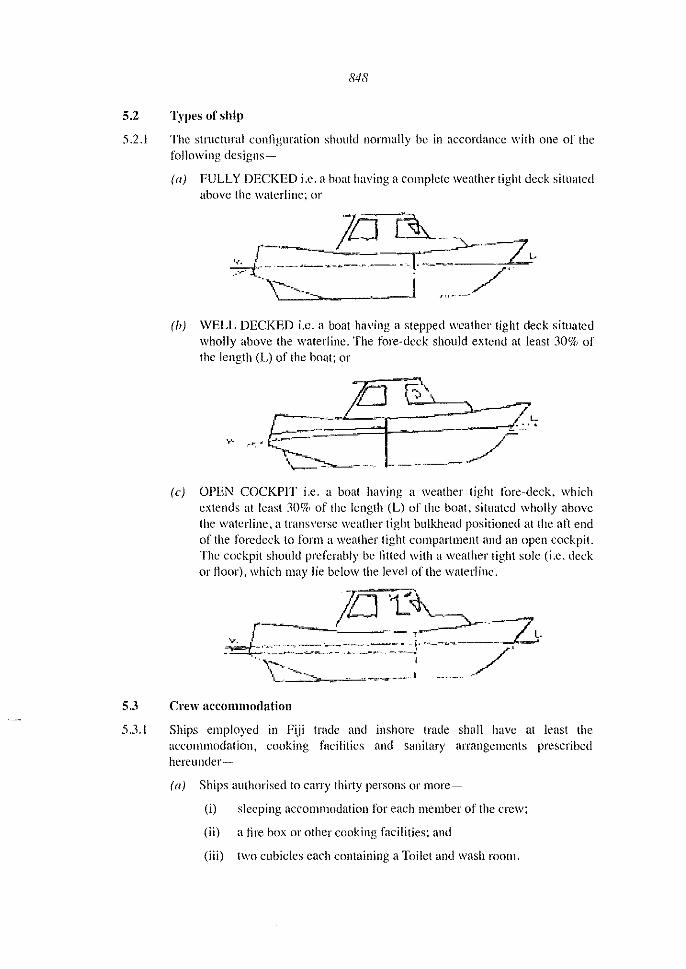
5.2 Types of ship
5.2.1 The structural conl1guration should normally be in accordance with one of the following designs~
la) FULLY DECKED i.e. a boat having a complete weather tight deck situated above the waterline; or
Ih) WELL DECKED i.e. a boat having a stepped weather tight deck situated wholly above the waterline. The fore-deck should extend al least 30% of the length (L) of the boat; or
Ie) OPEN COCKPIT i.e. a boat having a weather tight t()fe-deck. which extends at least 3D% of the length (L) of the boat. situated wholly above the waterline, a transverse weather tight bulkhead positioned at the aft end of the foredeck to form a weather tight compartment and an open cockpit. The cockpit should preferably be fitled with a weather tight sole (i.e. deck or floor), which may lie below tile level of the waterline.
5.3 Crew accommodation
5.3.1 Ships employed in Fiji trade and inshore trade shall have at least the accommodation, cooking facilities and sanitary arrangements prescribed hereunder-
(a) Ships authorised to carry thirty persons or more-
(i) sleeping aceomlllodation for each member of the crew;
(ii) a fire box or other cooking facilities; and
(iii) two cubicles each containing a Toilet and wash room.

849
(b) Ships authorised to carry less than 30 persons-
(i) sleeping accommodation for each mcmber of the crew;
(ii) a firc box or other cooking facilities;
(iii) one cubicle containing a toilet and washroom.
((') Ships authorised to carry less than len persons-
(i) sleeping accommodatiou for each member of the crew;
(ii) a fire box or other cooking facilities;
(iii) one cubicle containing a toilet; and
(iv) if voyage is morc than 12 hours a bathroom is also required.
5.3.2 In all ships where required, the places allotted to the crew for sleeping quarters shall be of such size and dimensions as to provide for each mall to be accommodated therein, a space of not less than 72 cubic feel (2m3) and of not less than 12 square feet (I m2) measured on the floor or deck of such places, and shall be equipped with-
(a) at least two ventilation openings not being port-holes or doors, one for inlet and onc for outlet, these openings to be of not less than 6 inches (ISO mm) in diameter;
(b) port-holes, windows or pieces of heavy glass in the decking above to allow for thc entry of sufficient light during day-light hours for reading purposes;
(c) electric light, in the case of a ship of which any other part is so lighted:
Provided that any place allotted to the crew for sleeping quarters shall be of such dimensions as to provide a spacc of not less than 216 cubic feet (6m3) and of not less than 30 square feet (2.8m2) measured on the floor or deck of such place.
5.3.3 The bunks for members of crew shall be at least 6 feet 3 inches in length by 2 feet 3 inches (1900 x 680 lllJ11) in width, and where they are double tiered be a least lO inches (250 mm) from the deck or flooring and have spaces between the lower and upper bunks of not less than 30 inches (760 nun) and a similar space between the upper bunks and the deck head or ceiling, and where the bunks are of built-in type and me built parallel with the side of the ship, be at least 4 inches( 100 mm) from the side of the ship.
5.3.4 In all ships places allotted to the crew as sleeping quarters shall be ventilated and lighted as efficiently as is practicable and to the satisfaction of the authority.
5.3.5 The interior of all places allotted as sleeping quarters or mess rooms on steel ships shall be either lined 01' cork-dashed.
5.3.6 All steel deck heads above places allotted as sleeping quarters or mess rooms, shall be either covered with wooden decking on top or lined underneath with at leasl two and a half inches (60 mm) of an insulating material approved by the Authority's surveyor.

850
5.3.7 The floors or deck of all places allotted as sleeping quarters or mess rooms, shall be well cHulked to prevent ingress of bilge watcr from engines, fuel, bilges or cargo.
5.3,g \Vhere paint lockers and crew's sleeping quarters have a common wall, such wall shall have a metal or other approved fire resistant lining.
5.3.9 \Vhere chain cables pass through sleeping quarters or mess rooms, such chains shall be encased in air-light metal casing,
5.3.10 Places allotted to the crew as sleeping quarters shall not be used for the storage of any supplies or goods other than the personal belongings of the crew members occupying such places.
5.3.11 Places allotted to the crew as sleeping quarters or mess rooms shall be completely painted a light colour at least once a year.
5.3.12 All places allotted as sleeping quarters, mess rooms, and lavatories shall be appropriately marked and in case of sleeping quarters shall indicate the number of persons they are to accommodate.
5.3.13 All lavatory cubicles on ships shall have at least
(i) a floor space of 61/a square feet (0.6 Ill);
(ii) a width of two feet (600 Ill); and
(iii) a ventilation opening of 4 inches (100 mm) in diameter.
5.3.14 All lavatory cubicles shall have a port~hole or window to allow for the entry of light and, in addition, shall on those ships, in which any other part is so lighted, be equipped with electric light.
5.3.15 All lavatory cubicles shall have an impervious floor and the lavatories shall have a flushing apparatus which discharge into a sewerage holding tank.
5.3.16 The interior of all lavatory cubicles shall be completely painted at least once every six months.
5.3.17 All engine rooms shall be provided with ventilation and shall not be used for sleeping quarters except with the special permission of the Chief Executive Officer. Provision shall be made to ensure noxiolls or exhaust gases cannot be discharged into any enclosed space to which any person has normal access.
5.3.18 Ships employed in the Fiji Trade, inshore service and sheltered water shall carry in appropriate storage tanks at least the following quantities of fresh water: 6 gallons (271itres) for each person the ship is authorised to carry up to a maximllm requirement of 40 gallons (180 litres).
5.4 Passenger accommodation - berthed and ullberthed
5.4.1 Berths for passengers travelling as berthed passengers shall be the same standard as specified in sub paragraphs 5.3.2 to 5.3 .12 inclusive.
851
5.4.2 Each unbcrthed passenger shall be provided with sealing accommodation of at least 460mm x 300 mill.
5.4.3 \Vhere the length of the voyage normally exceeds 6 hours, each unberthecl passenger shall be provided with level deck space of 1830 111m x 460 111m, which may include the seating accommodation specified in sub paragraph 5.4.2.
5.4.4 The spaces specified in sub paragraphs 5.4.2 and 5.4.3 shall be under a covcr or awning, such that the passengers are adequately sheltered from rain and spray.
5.4.5 Access between passenger spaces, lavatories and passenger emergency stations shall be adequate.
5.4.6 Ladder steps shal1 have a risc of between 200 mm and 225 nun and shall be of robust construction,
5.5 Galley spaces
5.5.1 Galley cooking areas shall be well ventilated to prevent heat accumulation on a combustible surface. The surveyor may require combustible bulkheads and deckhead close to the cooker to be insulated and steel lined.
5.5.2 Gas supplies for gas cooking shall be in standard gas cylinders securely fitted outside any enclosed space and so that any gas leakage, which maybe heavier than air, can gravitate away over the ship's side. All piping between the cylinder and the cooker shall be approved by the Chief Executive Ofl1cer. All gas piping should be made of copper or similar material.
5.6 'Vorkmanshil>, materials and scantlings
5.6.1 \Vorkmanship shall be in accordance with the best marine practice and to the approval of the Surveyors.
5.6.2 Laminated construction may be llsed wherever specifically approved. Laminations shall be of kiln-dried timber, bonded with resorcinol glues and properly cured before working.
5.6.3 The type and layout of the ship shall be as indicated on the builder's General Arrangement plan.
5.6.4 All materials, including fastenings, shall be as specified in the Regulations and to the approval of the Chief Executive Officer. Timber shall be of good quality, reasonably seasoned. Hull timber shall be treated with an approved wood preservative.
5.6.5 Plywood shall be of Marine Standard. The end grain of plywood shall be sealed. Where plywood is to be used in a fish room it shall be treated with an approved wood preservative.
5.6.6 All ironwork shall be hot galvanised or shot blasted and zinc sprayed or otherwise treated to the satisfaction of the Surveyor.
S.6.? Where aluminium alloy is used it shall be of a marine grade. An approved method of fastening and insulating between dissimilar materials shall be used. Lead-free paints (T8T free) shall be used with this type of material.

852
5.6.8 SCANTLING NUMERAL
(a) The scantling numeral shall be the product obtained by multiplying the Length (L) by Breadth (B) by Depth (D); and
(b) The scantlings for any ship shall not be less than those determined by reference to the appropriate Scantling Numeral. Scantlings arc tabulated in Tables I to XlI annexed to this section.
5.7 Constructional details (wooden ships)
This subsection applies to ships of wooden construction, but may be used as a guide to general requirements for construction in other materials, except that scantlings would require modifications to the particular material as approved by the Surveyor.
5.7.1 KEEL
The keel shall be of an approved hardwood and preferably in one length, but when it is necessary to scarp, the length of scarp shall be not less than five times the moulded depth of the keel. The scarp shall be of lock fast design, fastened in accordance with the regulations and shall not be situated in the way of the main engine. Scm-phs shall be kept clear of the hog and keelson scarps by at least 5 frame spaces. A steel keel band or wooden false keel shall be fitted. In the case of ships of the beaching type, the moulding scantling as given in the Regulations shall be increased by not less than 25 per cent.
5.7.2 HOG
The hog shall be of an approved hardwood moulded to the form of the ship and shall have a depth in accordance with the Regulations. If scarped, the scarph shall not be less than 5 times the moulding and shall be kept clear of the keel and keelson scmvhs, by not less than 5 times frame spaces.
5.7.3 STEM
The stem shall be of an approved hardwood sawn to shape, scarphed or tenoned to the keel, and connected by either a deadwood or heavy knee. In the case of a rounded fore-foot the scarph shall be of the lockl~1st design. In the case of a straight fore-foot, through fastened plates shall be fitted on either side of the stem and keel. A steel band or shoe shall be fitted. Where required an anchor cable clench plate shall be fitted.
5.7.4 APRON
The apron shall be in one length of (\11 approved hardwood sided Hnd moulded to the form of the ship and through bolted to stem.
5.7.5 FORE DEADWOOD OR KNEE
A fore deadwood or knee of an approved hardwood shall be fitted, sided to give adequate faying surface to plank ends, lipped over hog, scarphctl to apron and through bolted to stem and keel.

853
5.7.6 STERNPOST
The stern post shall be of an approved hardwood connected to the keel by tenon and heavy dovetaillskeg plates each side. In all cases the stern post shall be such that the thickness of timber remaining on either side of the sterntube aftcr the rabbet has been formed, shall not be less than one-quarter the thickness of the siding of the stern post. I f necessary the stern post Illay be swelled in way of sterntube to meet this requirement.
5.7.7 AFTER DEADWOOD OR KNEE
The after-deadwood or knee shall be of an approved hardwood fitted to keel and sternpost and swelled if necessary in way of the stcrntube in accordance with the regulations. Dowels or tenons shall be fitted at the joint with the keel.
5.7.8 OUTRIGGER
The outrigger on ships with a canoe or cruiser stern shall be of an approved hardwood sided as the stern post and Htted to the sternpost and after deadwood. Fashion pieces shall be fitted on each side of the stern post to give a t~'l)dng surface to the plank ends. The faying surface shall be not less than~
(a) 50 mill for ships lip to SN 30; and
(b) 75 nUll for ships of SN 45 and over.
The t~1shion pieces shall be through bolted to the outrigger and sternpost.
5.7.9 TRANSOM
On transom stern ships, the transom shall be constructed of solid, single or double planking on a suitable framework. \Vhere the single timber method is used, t~lshion pieces shall be bolted to the forward side in way of the plank ends to allow for additional plank fastenings clear of the end grain. \Vhere the double planked method is used, oiled calico or other approved material shall be fitted between the skins and the transom shall be suitably stiffened with vertical and transverse stiffeners. The transom shall be connected to the horn timber by a suitable knee.
5.7.10 TRANSOM KNEE
A transom knee shall be fitted in accordance with the regulations. \Vhen the mdder gland passes through the trnllsom knee, the siding of the knee shall be such, that not less than 25 per cent of the siding of the knee remains on either side of the rudder gland hole.
5.7.!I STOPWATER
Softwood stop water shall be fitted at all joints in way of plank rabbets.
5.7.12 FRAMING
All frames shall be of selected timber and may be either double or single type, steam bent or a combination of sawn and steam bent according to Type Classification.

854
5.7.13 SINGLE SAWN FRAMES
The frames can either be butted at the centre or fitted with floors or the floors may be formed by the lower frame futtocks, fitted on opposite sides on alternative frame stations. The butls of the remaining futtocks shall be joined by a damp of length not less than six times the siding of the frame on either side of the butt, and shall be staggered generally throughout the ship. Frame Hoors sided as per frame shall be fitted to and extend across the hog for a length of not less than one-third the breadth of the ship at that point. Clamps and floors shall be fastened to the frame by through bolts in accordance with the suitable limber holes to provide adequate drainage shall be arranged and limber chains or equivalent filted. Can't frames shall be tenoned or recessed into or connected with angle iron brackets to the fashion pieces.
5.7.14 DOUBLE SAWN fRAMES
Frame floors shall be fitted to and extend across the hog for the length of not less than one-third the breadth of the ship at each frame station. The lower frame futtocks shall be butted on the centre line and be fastened to the floors by through bolts in accordance with the regulations. Butts of remaining double futtocks shall be staggered and fastened in the same way.
5.7.15 Ships with a Scantling Numeral of 45 and less may be framed throughout with bent wood frames. In ships above this and with a Scantling Numeral of less than 140 framing may be of a combination of sawn and bent wood frames.
5.7.16 STRINGERS
Bilge stringers of an approved timber shall be fitted, and shall run fromlhe apron to the transom or outrigger. All scm-phs shall extend over two frames and be staggered port and starboard.
5.7.17 BREASTHOOKS
Breasthooks shaH be of a suitable hardwood or steel construction of approved design. Breasthooks shall be fitled to beam and bilge stringers and t~'lstened with at least three bolts in each arm, and through bolted to the stem and apron.
5.7.18 QUARTER KNEES
Quarter knees shall be fitted to bulwark rails on transom stern ships. These shall be of wood or steel as for breasthooks, and fastened with at least three bolts in each ann.
5.7.19 BEAM KNEES
Lodging and/or hanging knees shall be fitted to all main beams and beams in way of gallows, winches and deck leads. These may be of an approved hardwood or steel and fastened with at least two bolts in each arm. Knees on ordinary beams shall be to the approval of the Surveyor.

855
5.7.20 BEAMS
All main beams shall be of an approved hardwood. Ordinary beams shall be of an approved timber. Main beams shall be spaced in accordance with the approved drawing and ordinary beams in accordance with the regulations. All beams shall be moulded and sided in accordance with the regulations and may be moulded 25 mm less at the ends. Beams shall be fastened with bolts at the beam shield and frame heads. All beams shall have an adequate round of beam (camber), Half beams shall be sided as for ordinary beams and shall be housed and dovetailed into carlings.
5.7 .21 \Vhere a beam shelf is fitted, it shall be of an approved timber and extend for at least three-fifths the length of the ship. Scarphs shall extend over two frame spaces and be kept well clear of beam stringer scarphs and shall be staggered port and star board. The shelf shall be through hlstened at each frame.
5.7.22 CARLINGS
The carlings shall be of an approved hardwood, housed and dovetailed into the main beams. Lodging knees or steel brackets shall be fitted at each corner. Tierods shall be fitted to car lings in way of openings exceeding 2 metres in length. Steel carlings may be fitted to the approval of the Surveyors. Tie rods of 12 mm diameter shall be spaced not more than 1.2 metres. \Vhen the length of the carlings exceeds 2.50 metres the moulding shaH he increased by 10% and the carlings suitably supported by pillars.
5.7.23 PLANKING (Carvel)
The hull planking shall be of an approved timber. No plank width shall exceed four times its own thickness, except that the garboard and its adjacent strake and the two adjoining stt"akes to these aft to amidships, shall not exceed six times their thickness. All timber shall be free from sap, shakes and objectionable knots and normally worked heart to frame of lengths to ensure a good shift of butts. Butts shall not be spaced closer than four frame spaces in adjacent strakes and there shaH be at least three passing stl·akes between butts on the same frame.
The butts of the garboard stt"akes shall be kept well clear of the keel and hog scm"phs. Stealer planks may be titted aft and shall not be less in widtb at their tlm~ end than 1.5 times the plank thickness, to allow for adequate fastening. The butts ends of planking in steam bent frame construction shall be fastened to a butt strap of the same thickness as the planking and the butt strap shall have at least 6 mm of clearance at each frame to allow for drainage. Where the butt strap method is not lIsed planks shall be scarphed and the length of scalph shall not be less than five times the thickness of the planking.
5.7.24 PLANKING (Clinker)
The rap or lands of clinker planking shall be not less than the widths given in the regulations and at plank ends shall be bevelled and rabbeted to fair into the stem and stern rabbets and transom. Where possible strakes shall be in one length, but where scarphs afe necessary these shall not be less than 6.5 times the plank

856
thickness in length, and glued, Scarphs shall be feathered inside and stepped outside with the feather placed on a bent wood frame. \Vidths of planks shall not exceed 150 mm with the exception of the garboard strake which may be wider. There shall be at least three passing strakcs between scmvhs 011 the same frame. Wedges shall be /Wed behind bend wood frames in way of risings, stringers, gunwales and elsewhere to the approval of the Surveyor.
5.7.25 PLANKING (OTHER THAN CARVEL OR CLINKER)
Other methods of planking will be considered subject to details being submitted for approval of the Surveyors.
5.7.26 RUBBING STRAKES
Rubbing strakes where fitted, shall be in accordance with the regulations. The sheer strake and lowest strake shall be of an approved hardwood. The siding of these strakes shall be 25mm greater than the siding of the ordinary planking and they may be tapered at the ends to run inlO the plank rabbet at stem and stern. The ordinary planking may be carried up to the deck with a rubber of an approved hardwood sided twice the thickness of the planking, fitted to the factor of the sheer stake, and t:1ced with a gaJvaniscd copper iron.
5.7.27 BILGE STRAKES
The biJge strakes shall be of an approved timber and shall extend at least half the length of the ship.
5.7.28 BILGE KEELS OR ROLLING CHOCKS
Bilge keels or rolling chocks where fitted shall be of an approved hardwood fitted to the outside of the bilge planking and t~\stened with one through bolt at each frame. In the case of ships with bent wood framing, the fastening shall be through the bilge stringer and planking shall be Htted with filling pieces in way of all fastenings.
5.7.29 DECK PLANKING
The deck planking shall be of an approved timber, and if of soft wood suitable pressure treated with a preservative. Butts shall be spaced at least 1.5 metres apart and there shall be a minimum three passing stakes between butts on the same beam. Plank widths shall not exceed 125 111111, and butts on half beams should be avoided.
5.7.30 COVERING BOARDS
Covering boards shall be Htted in way of the bulwark stanchions and carried to the outside of the sheerstrake, alternatively the sheerstrake Illay be carried to the top of the deck and a covering board fitted to the face of the stanchions and chocks fitted between the stanchions in way of the covering board and the sheerstrake.

857
5.7.31 BULWARK
The bulwark stanchions shall be of an approved hardwood either fitted along-side frames or as a continuation of the frame upper futtack. The separate stanchions or extended upper futtock shall be fitled at very frame space for one-third of the length of the ship forward and aft, and at alternate frame spaces amidships. Scantlings shall be as determined by the regulations and the length of separate stanchions housed below deck, shall not be Jess than eight times the siding of the stanchions.
5.7.32 The bulwark rails shall be of an approved hardwood attached to the tops of stanchions by tenons and Jump fastenings or rail dogs. Freeing ports shall be fitted to the bulwark each side with an area of 0.2 cubic metres. Any gap between the bottOill bulwark plank and the deck will be considered a part of the freeing port area.
5.7.33 The wash strake shall be fastened to the stanchions so as to 1~1cilitate easy removal for periodic caulking of the backs of the stanchions with gaJvanised rails.
5.7.34 \Vhere hose pipes are fitted in way of bulwark planking, suitable pads shall be fitted alongside the stem apron and extended through covering boards and securely fastened to apron, topside planking and bulwark rails.
5.7.35 Fixed bulwarks shall have a minimum height 600 111111. This height shall be made up to a minimum of 700 mm by rails, or portable stanchions and wires. Openings between rails shall not exceed 380 mill.
5.7.36 BULKHEADS
The bulkheads shall be positioned as indicated onlhe builders approved drawing. One watertight bulkhead shall be lined.
5.7.37 \Vhere possible the after engine room bulkhead shall be watertight and entrance arranged clear of this bulkhead.
5.7.38 \Vatertight bulkheads whereof wood shall be of double skin construction. Fitted with felt or calico between, suitably stiffened, or of other approved construction and shall be water tested. Non-watertight bulkheads may be constructed with tongued and grooved boarding, marine ply, or other approved material fitted on suitable stiffeners.
5.7.39 Bulkheads which separate machinery space from accommodation shall be constructcd of incombustible matcrial.
5.7.40 Where watertight bulkheads are pierced watertight glands or doors shall fitted.
5.7.41 In all ships of the open type having no complete watertight deck and scantling. Numeral of less than 60, one watertight bulkhead shall be fitted forward of the engine space, and extended in height to the top of the risings and secured at the lOp to underside of thwart. In ships of this type having a scantling numeral of 60 and above a bulkhead shall be fitled at the end of the foredeck in addition to the engine space bulkhead.

858
5.7.42 GUNWALES
In all open type ships having no bulkwarks, gUllwales of an approved timber shall be fitted. Gunwale shall be of the box type fitted to the face of grown or bent frames with a capping fitted to the top and shall be through fastened at each frame. \Vhere the framing is a combination of grown and bent frames, filler pieces shall be fitted in way of the bent frames. A breast hook shall be fitled forward and either quarter knees or abreast hook aft.
5.7.43 RISINGS
In all open ships which do not have a watertight deck risings of an approved timber shall be fitted. The risings shall be through fastened at each grown or bent frame, and where framing is a combination of both, filler pieces shall be filled in way of bent frames. The risings shall be at the height of the thwarts where fitted, and not less than one-third of the moulded depth below lop of the gunwales in ships having no thwarts. \Vhere thwarts are fitted below the height of the risings nil additional stringer shall be-fitted.
5.7.44 THWARTS
In open type ships thwarts shall be fitted where indicated on the approved drawing. The thwarts shall be connected to the risings by through fastenings, clenched over rovers or washers and by thwart knees fitted to the tops and lodging knees to sides. The latter shall be fitted to the after side of forward thwarts and forward side of after thwarts.
5.7.45 FORECASTLE
The forecastle where not used .IS accommodation, shall be fitted out as a store, with shelves and racks for the stowage of gear, and provided with an approved access,
5.7.46 HOLD
\Vhere ceilings are fitted, they shall be of an approved timber, kept well clear of frames and ventilated by not less than two each side, self-closing swan-neck ventilators, situated one at each end. In each case a centre gully shall be fitted to drain into a pump suction well of the hold. All softwood shall be treated with an approved preservative.
5.7.47 HATCHES
The hatch coamings shall be of either approved hardwood dovetailed at corners, steel or other approved material, and be fitted with all necessary securing fittings and covers to ensure weather-tightness.
5.7.48 \Vooden hatch covers shall have a finished thickness of at least 40 mm in association with a span of I metre and a width of bearing surface at each end of not less than 65 mm. Hatch covers other than of wood shall be of equivalent strength. All portable hatch covers to be permanently marked to indicate their correct position.

859
5.7.49 The height of hatch coamings above the deck shall be not less than 300mm.
5.7.50 The forward store hatch shall be weather tight, constructed with a hinged cover and with securing clips. The hinges shall be fitted at the forward L'oaming. \Vhcn the accommodation or the engine room is situated forward, an access companion way with a sill height complying with 6.3 and a weather tight cover-door shaU be lilted.
5.7.51 Other deck openings which arc essential for operations may be of the flush deck type; provided they can be closed weather tight with covers permanently, attached to the hull stl1lClurc.
5.7.52 LADDERS
Fixed and portable ladders, handholds and other devices simi I be provided for the safe working of the ship at sea and in port and shall have adequate dimensions, AlImctal, rope and wooden ladders shall be of material, construction and strength to the approval of the Surveyor.
5,7.53 The treads on all ladders shall be flat and prepared to minimise slipping, Fixed Vertical ladders shall be situated to give adequate toe clearance. Hand holes shall be provided if the rungs or stringers are not suitable for this purpose.
5.7.54 Engine room and accommodatioll ladders shall be fitted with nOll-slip treads and adequate handrails and constructed with incombustible material.
5.7,55 Portable ladders shall stand on a llrm base and shall be capable of being secured at the top.
5.7.56 ENGINE SEATS
\Vooden engine seats shall be of an approved hardwood and shall extend at least twice the distance between the engine gear box output coupling and the forward engine holding down bolt centre, reduced in depth clear of the engine as necessary, and checked over every frame or noor, but kept clear of planking. They shall be stiffened with brackets at every second frame and reinforced with not less than three cross members. The side brackets and cross members where of wood shall be connected to the engine seats by bolting to angle bars of approved dimensions.
5.7.57 The engine scats shall be through fastened at each frame or alternatively through frames and planking, Provisions should be made to ensure that the bolts call be tightened during service. All bolts shall have plate washers, A steel plate, channel or angle bar shall be fitted to the tops of the engine seats extending throughout the length of the engine and gear box. The engine holding down bolts shall where practicable pass through the full depth of the scats or be secured by plate or barrel nuts recessed into the scats. \Vhere the latter method is used, bolt lengths shall be varied so as to stagger recesses. Alternatively, where heavy top angles or channels are fitted to the engine seats, the angles or channels shall be secured through the full depth of the seats where practicable and the engine holding down belts fitted through the top flange only.

860
.').7.58 In ships constructed with bent wood frames, the engine seats shall be mounted on and not<:hed over additional cross floors extending to the bilge on each side and spaced not more than 'three-quarters of the distance between engine seals.
5.7.59 Where steel seats arc titted, they shall be fabricated and tilted with side brackets 011 every second frame and with not less than three, inlercostals. The seat shall be connected to the frames either by angles and brackets or by welded plates. The sole plate shall be of adequate thickness for the lype and size of engine to be installed. The method of construction in these cases shall be submitted to the Surveyor for approval.
5,7,60 For powers of 150 Kw (200 hI') and over,lhe tilting of sleel seats is preferred, Proposals for engine seats shall be submitted for the approval ofthe Surveyors.
5.7.61 For guidance the sidings of wooden engine seats shall be in accordance with the following-
A1aximli1ll kw (hI') Minimum Siding (~l Engine Seats
Tip to 22kw (30 hpj 85mm
UP to 75 kw (100 hpj 110mm
UplO 130kw (175 hI') 140 mm
Up to 185 kw (250 hI') 150 mm
Lip to 225 kw (300 hI') 180 mm
Up to 300 kw (400 hpj 200 mm
5,7,62 POOP DECK OR CASING
\Vhere a raised casing is fitted over the engine room and/or cabin, the plating shall not be less than 6 111m thickness and suitably stiffened.
5,7,63 WHEELHOUSE AND DECKHOUSE
Where an aluminium alloy wheelhouse is approved the plating shall be not less than 5mm thickness with stiffeners spaced not more than 460 mill. \Vhere built of steel the stiffeners may be placed not more than 730 mm.
5.7.64 A wooden wheelhouse shall be of hardwood framing with substantial coamings and planked with an approved timber, or arranged in panels of marine quality plywood. The top shall be covered with a first quality canvas and painted, or sheathed with nylon or other approved materials.
5.7.65 For constructions llsing material other than any of the above, details shall be submitted for the approval of the Surveyors.
5.7.66 In ali cases access to the top of the wheelhouse shall be ananged.
5.7.67 Windows, at least one~third of which shall be of the opening type, maybe of the metal type or wood framed railway type. Adequate window drainage shall be provided. Window glass shall be not less than 10 111m thick and toughened.

861
5.7.68 Linings shaH be plywood, plastic sheeting or other approved materials, special atlention being given to tire prevention.
5.7.69 \Vhcrc a dcckhousc is fitted. the construction shall be similar to that required for the wheelhouse and be of wood, steel, aluminium or other approved material.
5.7.70 Sufficient handrails shall be provided outside of wheelhollse, deckhouse and casing and inside wheelhouse, passageways, accommodation and engine room.
5.7.71 RUDDER
The rudder shall have a stock of steel in accordance with the regulations with welded or keyed (Slipped on) couplings. A watertight gland with a bearing shall be fitted to the hull. \Vhcn the stock extends more than 460 111111 above the inboard gland, an additional bearing suitably supported shall be Hued at top under deck. Stainless steel sleeving on the stock in way of bearings shall be fitted. The scantling shown in the regulations shall be regarded as a guide only. The actual size shall be determined by the length, shaft horse power, speed of the ship and type and area of rudder to be fitted. The lower pintle shall be fitted into a bushed socket at the skegplate, and ajumping band fitted below the rudder gland at top of I1Idder if required. Arrangements arc to be made for the lubrication of bearings.
5.7.72 A steel quadrant or tiller shall be litted to the stock. Stops shall be fitted to limit the angle of rudder to not more than 35° on each side.
5.7.73 If the rudder blade is of wood, steel straps shall be welded to the stock and fastened to the blade by through boits. If the rudder blade is of steel it may be of single or double plate construction welded to the stock and fined with suitable stiffeners. If of double plate construction it shall be fitted with suitable material and fitted with a drain plug. Pintles and gudgeons of steel or other approved metal shall be fitted.
5.7.74 STEERING GEAR
The steering gear shall be of an approved type and size. A non-geared gypsy type of steering gear with wire lends Illay be fitted. An approved emergency steering arrangement shall be provided. \Vhere hydraulic steering gears are fitted, they shall be mounted on rigid seatings to the approval of the Surveyors.
5.7.75 MASTS
Masts as required for the type of ship shall be fitted either of timber, stcel, or other approved material.
5.7.76 DERRICKS
Derricks if required for the type of ship shall be supplied either of timber, steel or other approved materials. The maximulll safe working load and maximum radius of operation of all derricks shall bc stated in the approved specification. The derricks, their ropes, wires, guys, eye plates and other associated equipment shall be designed to meet these loads. Derricks shall be tcsted as rigged for service to not less than 1.5 times the maximum working load. The maximum safe working load shall be permanently indicated on the derricks.

862
5.7.77 FASTENINGS
All steel fastenings, unless otherwise specihed, shall be galvanised. Bolts shall be made from rolled mild steel bar and the diameter shall be in accordance with the regulations. \Vherc bolts arc cropped. the exposed ends shall be coaled with zinc paint. Flats and dumps shall be of length in accordance with the following.
Thickness (~rTil1lher Length (~rFI(fts or Dumps (}]lIn) (11/111 )
25 75 30 90 35 100
45 115
50 125
65 150
70 165
75 175
90 205 100 225
5.7.78 COPPER NAIL FASTENING
Thickness (~rTil11her (/11m) Dhfll1eter of Nail (111111)
12 2.50
13 2.80
20 2.80
25 :1.35
30 3.35
35 3.35
45 3.35
50 3.35
55 3.75
65 3.75
70 3.75
75 4.00
80 4.00
85 5.00
100 5.00
115 5.00
130 5.60
150 6.00
5.7.79 THROUGH BOLTS
Through bolts in these regulations mean either nut or screw or clenched bolls.
863
5.7.80 KEEL AND HOG
Shall be fastened together by Hats or screws between every second frame space.
5.7.81 KEEL AND KEELSON
Shall be fastened through each floor timber by through bolts.
5.7.82 KEEL SCARPHS
Shall be fastened by nut and screw bolts, one through each frame floor and one between each frame in way of seraph.
5.7.83 FRAME FUTTOCKS AND CLAMPS
Shall be t:1stellcd by not less than four through bolls on each side of the butt. Not less than three bolts shall be fitted on eaeh side of the butt.
5.7.84 FRAME FLOORS
Shall be t:1stened to hog and keel, with one through bolt at each floor. Futtocks shall be fastened to the frame floor by not less than four through bolts on either side.
5.7.85 BULWARK STANCHIONS
Shall be fastened by not less than :1 through bolts through frame and 2 through hull planking. The bolt sizes to be as for frame fastenings.
5.7.86 BEAM STRINGERS
Shall be fastened with one dump and one through bolt at each frame.
5.7.87 BEAM SHELF
Shall be fastened with one through bolt at each frame.
5.7.88 BILGE STRINGERS
The beam stringers, shelf and bilge stringers shall be fastened with one through t:1stening at each frame.
5.7.89 STEM AND APRON
The apron shall be securely t~lstened to the stem by through bolts.
5.7.90 HULL PLANKING (CARVEL)
Shall be fastened by two clenched t:1stenings at each sawll frame or bent wood frame, and two clenched copper fastenings in plank lands between each frame, where the frames are spaced more than 150 mm apart and one fastening where the spacing is less than 150 111m. Plank ends at stem and stern shall he fastened at the rabbets by 110t less than four screws in each plank. In the case of a transom stern, the planks shall be fastened at the transom with not less than three screws in each plank and two screws in each plank in way of the transom fashion pieces. Butts, if used, shall be secured to butt blocks or planks may be scarphed together.

864
5.7.91 THROUGH FASTENINGS (PLANKING)
In all cases whatever the method of planking adopted, all through fastenings in way of stringers shall pass through the planking.
5.7.92 DECKING
Shall be fastened at each beam with one flat or dump when the width of the deck plank is 100 nun or less and two Oats or dumps when the width exceeds Ihis. The fastenings shall be recessed and holes filled with edge grain dowels.
5.7.93 BEAMS
Shall be fastened to beam stringers and beam shelves by through bolts. Lodging and hanging knees shall be through fastened to beams and frames with not less than two bolts in each arm.
5.7.94 ENGINE SEATS
Shall be through bolted through frames or frames and planking at each thune.
5.7.95 CARLlNGS
Shall be dump or screw fastened to beams and stiffened at each corner with a wooden knee or angle bracket.
5.7.96 WOODEN BULKHEADS
Shall be fastened to frames, beams and stiffeners with galvanised nails and screws. When of double skin construction all nail fastenings through planking shall be turned, or clenched on roves.
5.7.97 WHEELHOUSE
Shall be secured by through bolts and plate washers spaced not more than 115mm apart.
5.7.98 MASTS
Tabernacles shall be through fastened to beams and stiffeners.
5.7.99 GALLOWS, WARPS, BOLLARDS AND LEADS
Shall be through fastened through beams. The space between the beams shall be fitted with filler chocks, and a steel plate or hardwood pad titted to the underside of chocks and beams. \Vhere leads are fastened to the bulwarks they shall be through bolted and bulwarks suitably stiffened.
5.7.100 PAINTWORK
(a) All paints to be applied to the hull of the ships are to be in compliance with the marine (anti fouling systems on ships) regulation and of marine application. Varnishes, wood preservatives, anti-fouling and bitumen compositions shall be of approved commercial marine standard and quality. Colours to be of owner's choice. Paints used in engine room and accommodation spaces shall be of low flame spread characteristics.

865
(b) Before any paint is applied, all timber which has not been previously pressure impregnated with preservative, shall receive not less than three coats of preservative liberally applied. All slraight lengths of timber, such as decking, timber for bulk-heads, floorings and ceiling, etc., shall be pressure treated with a preservative before fitting. All ends surfaces exposed through cutting during fitting and fairing shall be liberally coated with preservative.
5.7.101 Except as may be otherwise specified herein the hull (internally) shaH receive not less than three coats of paint. In way of ceilings and bilges this may be substituted by two coats of bitumen composition.
5.7 .102 Hull (externally) above the waterline, shall receive not less than three coats of paint or varnish and below the waterline not less than two coats of bitumen composition, or two undercoats and one coat of anti-fouling composition which needs to comply with maritime anti-fouling regulations. The anti-fouling composition shall be applied immediately prior to launching.
5.7.103 Wood superstructure shall be either varnished or painted. If painted not less than three coats shall be applied and if varnished four coats.
5.7.104 Bulwarks, stanchions and hatchways shall receive not less than three coats of paint.
5.7.lO5 Decks may be left unpainted, but when painted, paint shall be of the non-slip type or alternatively fine silver sand may be sprinkled over ordinal), paint whilst it is still wet.
5.7.106 The hold, if painted shall receive not less than three coats of paint to lhe satisfaction of the Surveyors.
5.7.107 The cabin (except where lined with plastic faced sheeting) shall be either painted, grained, or varnished, with at Icast three coats.
5.7 .108 The engine room shall be coated throughout with alleasl three coats. Tanks and pipe work with the exception of copper or galvanised piping and all other metal fittings shall be painted with alleast three coals of anti-corrosive paint.
5.7.109 Steelwork that is not galvanised shall be wherever possible, shot-blasted and either metal sprayed or coated with an epoxy resin-based or other high duty steel primer. During construction all welding and cut edges and other breaks in the primed surface shall be thoroughly cleansed and coated with a suitable primer. Subsequently, the stcel shall receive one further coat of primer all over, followed by one undercoat and one finishing coat.
5.7.110 Steelwork that is neither galvanised nor shot-blasted shall be thoroughly cleaned of all rust and scale and given two coats of high duty steel primer, followed by one undercoat and one finishing coat.
5.7.111 Aluminium alloys shall be degreased,elch primed and COaled with azinc chromate paint before working, and two unuercoats and one finishing coat applied. Paints containing lead, mercury or copper shall not be used on aluminium alloys.

866
5.7.112 PROTECTIVE OR UNDERWATER METALS
An approved method of cathodic protection shall be fitted to all ships to reduce or eliminate corrosion.
5.7.113 MARKINGS
The lettering and numbering of ships shall be in accordance with the regulations for the Registry. Lettering and Numbering to Fiji Registry Requirements. Draught marks and loadlincs shall be welded on or cut in at bow and stern. port and starboard and amidships.
5.7.114 CAULKING
(a) Plank seams on ships of carvel construction shall be caulked with best quality caulking cotton, All seams below the waterline shall be painted with pitch, marine glue or stopped with another approved composition. Topsides shall be caulked and stopped with best qualily white or red lead putty and all seams shall be painted prior to stopping;
(b) On ships constructed with clinker type planking, the garboard seams and hood end seams shall be caulked with best quality caulking cotton, painted and stopped with best quality white or red putty or other approved composition;
(c) The deck scams shall be caulked with best quality cotton, and paved with marine glue or other approved composition; and
(d) Caulking of planking and decks is to be carefully executed. When finished, caulking should be hardened down to approximately 9 mm below the sUlt'ace of the plank to allow for paying up or stopping.

ANNEX I
SCANTLING TABLES I TO XII
TABLEl
KEEL Stern Scantling
Mid. Sdg. Post Numeral
(mm) (nun) Sdg. SAME
10 125 90 AS KEEL
SAME 15 150 90 AS
KEEL
SAME 18 150 100 AS
KEEL
SAME 20 150 100 AS
KEEL
SAME 25 175 100 AS
KEEL
SAME 30 175 115 AS
KEEL
SAME 45 180 125 AS
KEEL
SAME 60 180 125 AS
KEEL
SAME 70 280 125 AS
KEEL
SAME 85 205 140 AS
KEEL
SAME 100 230 150 AS
KEEL
867
Stem Apron KEELSON HOG Mid. Mid. Sdg. Mid. Sdg. Sdg. (mm) (mm) (mm) (mm) (nun)
SAME AS 65 25 x 150
KEEL
SAME AS 65 30 x 150
KEEL
SAME AS 75 40 x 165
KEEL
SAME AS 75 40 x 165
KEEL
SAME AS 75 45 x 165
KEEL
SAME AS 90 50 x 190
KEEL
SAME AS 90 50 x 190
KEEL
SAME AS 90 65 x 205
KEEL
SAME AS 90 75x215
KEEL
SAME AS 90 75 x 240
KEEL
SAME AS 100 90 x 270
KEEL
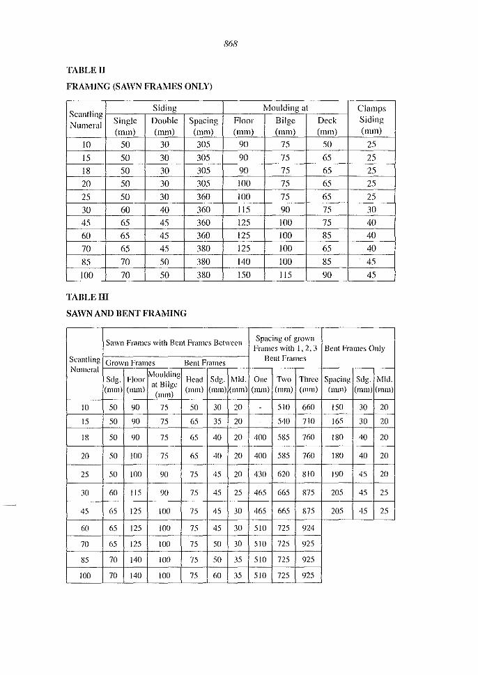
868
TABLE II
FRAMING (SAWN FRAMES ONLY)
Scantling Siding Moulding at Clamps
Numeral Single Double Spacing Floor Bilge Deck Siding (mm) (nun) (mm) (mill) (mill) (mm) ( mm)
10 50 30 305 90 75 50 25
15 50 30 305 90 75 65 2S
18 50 30 305 90 75 65 2S
20 50 30 305 100 75 65 25
25 50 30 360 100 75 65 2S
30 60 40 360 115 90 75 30 45 65 45 360 125 100 75 40 60 65 45 360 125 100 85 40 70 65 45 380 125 100 65 40
85 70 50 380 140 100 85 4S
100 70 50 380 ISO 115 90 45
TABLE III
SAWN AND BENT FRAMING
Sawn Frames with Bent Frames Between Spacing of grown Frames with 1,2.3 Bent Frames Only
Scantling Grown Frames Bent Frames Bellt Frames Numeral
J\'iollkling Sdg. Floor Head Sdg. Mid. One Two Three Spacing Sdg. Mid.
(mill) (mm) at Bilge
(mm) (mm) ( III Ill) (mm) (mm) ( Illlll) (nun) (mm) (mIll) (mill)
10 50 90 75 50 30 20 510 660 150 30 20
15 50 90 75 65 35 20 - 540 710 165 30 20
18 50 90 75 65 40 20 400 585 760 180 40 20
20 50 JOO 75 65 40 20 400 585 760 180 40 20
25 50 100 90 75 45 20 430 620 810 190 45 20
30 60 115 90 75 45 25 465 665 875 205 45 25
45 65 125 100 75 45 30 465 665 875 205 45 25
60 65 125 100 75 45 30 510 725 924
70 65 125 100 75 50 30 510 725 925
85 70 140 100 75 50 35 510 725 925
100 70 140 100 75 60 35 510 725 925

869
TABLE IV
PLANING (CARVEL), STRAKES, STRINGERS, BEAM SHELF
Hull and Strakes stringers Scantling Deck
Sdg, Bilge Rubbing Beam Shelf
Numeral Planning Bilge Beam (em2)
(mm) (mm) No, No, (em2) (em2)
10 20 45 I - 20 - -
15 20 45 I - 20 - -
18 20 45 I - 25 - -
20 20 50 I - 25 - -
25 25 50 I - 30 - -
30 25 50 I - 30 - -
45 30 55 I - 35 - -
60 30 55 I I 50 65 65 70 30 60 I 2 50 75 65 85 35 60 1 2 50 75 65 100 40 60 I 2 65 90 65
TABLE V
PLANKING (CLINKER), RISING, GUNWALES, eAPPINGS
Scantling Hull Deck Risings Gunwales Cappings
Numeral Planking Planking Sdg, Mid, Sdg, Mid, Sdg,
(nun) (mm) (mm) (mm) (mm) (mm) (mm)
10 125 20,0 25 65 25 75 20 15 12,5 20,0 25 65 25 75 20 18 15,0 20,0 25 70 30 75 20 20 15,0 22.5 25 70 35 75 25 25 15,0 225 30 75 40 75 25 30 20,0 25,0 35 75 40 90 25 45 20,0 27.5 35 75 40 90 30 60 22.5 275 40 75 50 100 30

870
TABLE VI
LAND OR I,AP WIDTHS
Scantling Numeral
10
15
18
20
25
30
45
60
TABLE VII
TRANSOMS
Scantling Numeral
10
15
18
20
25
30
45
60
70
85
100
Plank Thickness \Vidth of Land or Lap (mm) (mm)
12.5 20
12.5 20
15.0 25
15.0 25
15.0 30
20.0 30
20.0 30
22.5 30
Type (Thickness)
Double Skin Solid Conslruction Transom Knee
Construction (mm) Sdg.(mm)
(mm)
10 30 75
10 30 75
15 40 85
20 40 85
20 45 100
20 45 110
20 45 110
20 50 115
20 50 115
25 50 125
25 50 125

TABLE VIII
BEAMS
Scantling Numeral
10 15 18 20 25 30 45 60 70 85 100
TABLE IX
Main Beams Siding (mm)
65 65 70 70 75 75 90 90 90 90 95
871
Close Spacing
Ordinary Beams Moulding at Siding Centre (mm) (mm)
35 75 35 75 40 90
40 90 45 100 50 100 50 110 60 110 60 115 65 125 65 125
CARLINGS, BEAM KNEES, THWARTS AND KNEES
eadings Beam Beam Thwarts
Scantling MId. Sdg. Knees Knees Siding
Numeral (mm) (mm) Hanging Lodging (mm)
Sdg. Sdg. 10 - - - - 45 15 - - - - 45 18 - - - - 50 20 - - - - 50 25 - - - - 50 30 - - - - 55 45 - - - - 60
60 110 90 75 75 -
70 110 90 75 75 -
85 115 90 75 75 -
100 115 90 75 75 -
Spacing (mm)
280 280 305 305 360 360 360 360 400 400 400
Thwat1 Knees Siding (mm)
30 30 40 40 45 45 45 -
-
-
-

TABLE X
BULWARKS
Scantling Stach ions
Numeral Siding (null)
70 75
85 85
100 85
TABLE XI
Planking Siding (null)
20
20
20
872
Washstrake Rails Siding Sdg. MId. (mm) (null) (mm)
25 125 50
25 125 50
25 125 50
BOr;I'S: MINIMUM DIAMETRES
Scantling Keel: Apron Beams and Risings, Stem, Stern and Beam Shelf Stringers and
Hog (mm) Gunwales (mm) (mill)
JO 10 6 6
15 10 6 6 18 10 6 6
20 JO 6 6
25 12 8 8
30 12 10 JO
45 12 10 10 60 12 10 JO
70 12 10 JO
85 12 10 JO
100 16 12 10
Stringers
Sdg. MId. (mm) (mm)
100 50
100 50
100 50
Frame, Champs and Futtocks
(mm)
6 6
6
6
8
JO
JO I()
10 10 10
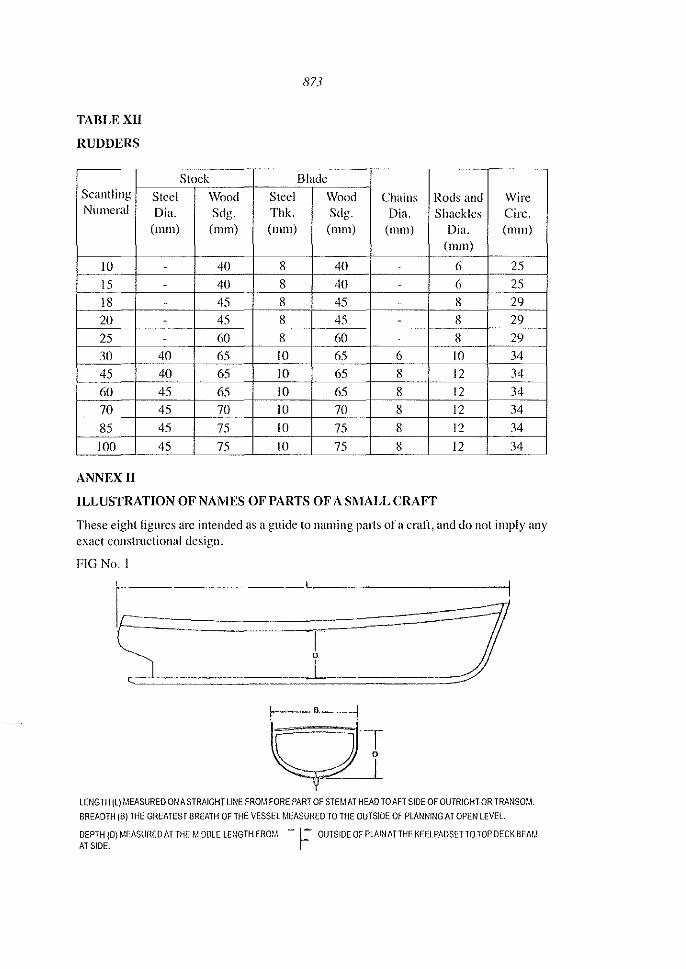
TABLE XII
RUDDERS
Scantling Numeral
10
15 18 20 25 30 45 60 70 85 100
ANNEX II
Steel Dia.
(mm)
-
-
-
-
-
40 40 45 45 45 45
Stock
Wood Steel Sdg. Thk.
(mm) (mm)
40 8 40 8 45 8 45 8
60 8
65 10 65 10 65 10 70 10 75 10 75 10
873
Blade
\Vood Chains Rods and Sdg. Dia. Shackles (mm) (mm) Dia.
(mm)
40 - 6 40 - 6 45 - 8
45 - 8
60 - 8 65 6 10 65 8 12 65 8 12 70 8 12 75 8 12 75 8 12
ILLUSTRATION OF NAMES OF PARTS OF A SMALL CRAFT
\Vire Cire, (mill)
25 25 29 29 29 34 34 34 34
34 34
These eight figures arc intended as a guide lo naming parts of a cran, and do not imply any exact constructional design.
FIG No.1 __ ... __ ~ ___ L~ _________ -I
I~ 0.
LENGTH (L) MEASURED ON A STRAIGHT LINE FROM FORE PART OF STEMAT HEAD rOAFT SIDE OF OUTRIGHT OR TRANSOM.
BREADTH (8) THE GREATEST BREATH OF THE VESSEL MEASURED TO THE OUTSIDE OF PLANNING AT OPEN LEVEL
DEPTH (0) MEASURED AT THE MIDDLE LENGTH FROM - 1- OUTSIDE OF PLAIN AT THE KEElPADSETTOTOP DECK BEAM AT SIDE. r

874
All measurements are to be in metres
FIG No.2
(",,; , _'"'' AfTERHOOX
, .... fASH:O~1 p,Ee _ ~
' FORWARD BREAST HOOK .. v ..
',.
SECT:O~l THROUGH KEElNm HOG
... ~ ............................ --
FIG No.3
~dd=.d ... d ...... JlJjJUUIJIJi1l5j±n~ .
• __ ........... ~ .. ~._ .... ~u ...... _ ,_ ._.-. .. .. . ~.- ",.._ ...
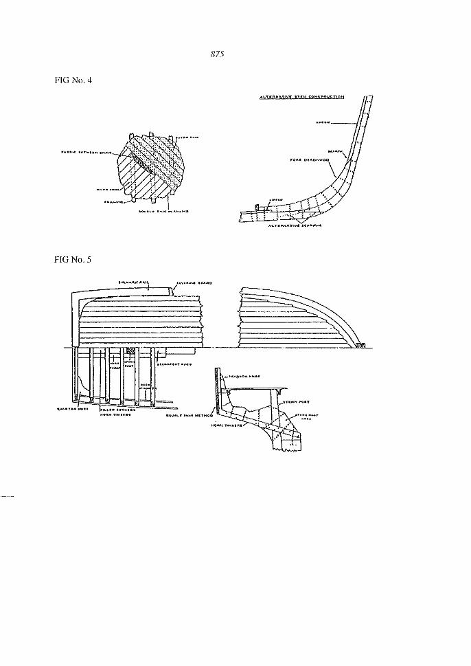
875
FlG No.4
................... -.
'.
FIG No.5
", 1<"""""'" .0"'''0
-
~ ~ ~ ~ fI-' ..... "_n~" ..
I~ .. . y =
.. u ........ ,~ ... .........

876
FIG No.6
j'
" .\ ,. !.
SECTION hf"'l'<tt !CW,t
FIG No.7
FIG No.8
.... ~ .............. , ............ ..........----~.,.,..-
--~ ... " ..... ".
Editor's Note: The Labels in FIG. No, 1 10 FIG No, 8 are lInclear due to electronic
reproduction.

877
PARAGRAPH 6
LOADLINES
Contents
6.0 General 6.4 Owners and Masters obligation 6.5 The deckline and load line mark 6.6 Freeboard 6.7 Conditions of Assignments 6.S Validity of the assigned freeboard 6.9 Assigned freeboard
6.0 General
6.1 All ships licensed to trade shall be assigned a freeboard.
6.2 A loadlinc as described in paragraph 6.4 shall be permanently marked, each side of the ship amidships, so that the centre of the disc indicates the assigned freeboard below the upper edge of the freeboard deck. If there are port holes below the freeboard deck, the freeboard shall be calculated as below the lowest part of the port opening. The deckline shall, however, always be shown at the actual deckline. For ships without a continuous deck the freeboard shall be measured below a fore and aft horizontal line through the lowest point on the gunwhale.
6.3 Ships trading within sheltered waters only may not be required to show the load line mark at the discretion of the surveyor appointed by the Chief Exccutive Officer or an authorised person.
6.4 Owners and l\llastcl's obligation
6.4.1 The owner and the master of a ship to which this section applies shall not allow the ship to proceed on a voyage unless it is surveyed, maintained and marked in accordance with the requirements of this section.
6.4.2 The master of a ship to which this scction applies shall ensurc that the appropriate load line marks on each side of the ship amidships are not submerged at any time when the ship commences a voyage, during the voyage, or on arrival.
Any master of a ship who fails to comply with sub section 6.4 commits an offence and is liable upon conviction to a fine not exceeding $2000 or imprisonmcnt of up to 3months, or both.
6.5 The deckline and loadline mark
6.5.1 The load line mark shall be parallel to the deck at each side amid ship and shall consist 01'-
(a) A horizolltallinc 300mm long and 25mm wide; and
(1)) A disc, centred on the upper edge of the line and of 80 nUll outer radius, 60 mm inner radius.

878
6.5.2 The loadline shall be-
(a) For steel and aluminium ships, pre-cut components welded on to the hull or by cutting in or centre punching;
(h) For \Voaden ships, cutting in to a depth of 3mm into the wooden planking;
(c) For FRP ships, pre~cllt component fixed on the ship with structural glue; or
(d) marked that it cannot be easily obscured or removed. It shall be painted a colour conspicuous from the hull colour.
6.5.3 A deck line 300 millimetres long by 25 millimetres wide shall be permanently marked amidships on each side of the ship nbove the loadline mark in accordance with sub-paragraph 6.52.
6.5.4 The deckline's upper edge shall pass through the point where the continuation outwards of the upper surface of the freeboard deck intersects the outer surface of the hull shell.
6.6 Freeboard
6.6.1 For all ships having a continuous watertight deck and where hatchways are secureu watertight by steel covers or equivalent means:
200 millimelres
6.6.2 For all ships having a continuous deck and where hatchways are secured watertight wooden boards and tarpaulins:
250 millimetres
6.6.3 For all ships which arc open or only partly decked:
10 metres length .......................................................................... 500 millimetres 6 metres or less inicngth ............................................................. 400 millimetres Freeboards for intermediate lengths arc to be obtained by linear interpolation.
6.6.4 In addition to the freeboard assigned in sub-paragraphs 6.6. I, 6.6.2 or 6.6.3 abovc, the freeboard shall if necessary be increased for carriage of passengers, such that if all the passengers the ship is liccnced to carry arc placed on onc extreme side of the ship on the uppermost deck, while the ship is fully loaded, the resultant list will not submerge the loadline more than 50% of such freeboard assigned.
For this purpose, it is assumed 13.6 persons weigh one ton.
6.7 Conditions of assignment
6.7.1 Ships licenced to traue in the Fiji Trade (territorial waters voyage) shall so far as possible comply with the conditions of assignment of ships of their class of 15 metres and over in length as specified in Section 7 of the "Maritime (Fiji Maritime Code) Regulation 2014.
879
6.7.2 \Vhere freeboards are proposed to be assigned to a ship in accordance with this section, they may be assigned only if the general structural strength of the ship is sufficient to permit it to be loaded to the draughts corresponding to those free boards.
6.7.3 Ships licenced to trade in the sheltered waters and Inland \Vater service may meet a less stringent standard at the discretion of the Chief Executive Officer.
6.8 Validity of the assigned free board
The assigned freeboard shall remain valid for the period of the validity of the Certificate of Survey subject to the ship not having sustained alterations in design or operation nor excessive damage to hull superstructure, or watertight integrity.
6.9 Assigned Freeboard. The assigned freeboard shall be shown on the Survey Certificate.
Contents 7.0 7.1
7.0
General Inclining test
Genel'al
PARAGRAPH 7
STABILITY
The stability of ships 15metres or less in registered length may be considered satisfactory if the metacentric height (GM) in the worst anticipated condition of loading is not less than 0.75 m and the angle of deck edge immersion at the point of lowest freeboard is not less than 14°.
7.1 Rolling Pcdod Test (inclining test)
For the purposes of paragraph 7.0 above, the ship may be subject to a Rolling Period Test and the GM obtained from the following formula:
GM=
where
f,ll )' T,
GM = metacentric height (metres)
B = moulded breadth of ship (metres)
Tr = time for one complete oscillation (i.e. for one complete roll port-starboardport or vice versa) (seconds)

880
F,:::: rolling period factor determined from the following table:
Conditions (~lships
(a) Emptyship ..................................................... .
(b) Shipscarryingball<lst ........................................ .
(e) Ship fully loaded <lnd with liquids in tanks comprising the following percentage of the total load on board (i.e. cargo, liquids, stores, passengers etc.)
(I) 20 per cellt of total load ...................................... .
(2) JOpercelltoftotalload ....................................... .
(3) 5 per cent of total load ...................................... .
(Order of accuracy of factors + or - 0.05)
Rolling perh}(lf(fctor
(J.88
0.88
(J.78
0.75
0.73
7.2 To determine the time for a complete oscillation (t) the following precautions should be observcd-
(a) The test should be conducted with the ship in harbour, in smooth water and with the minimum interference from wind and tide;
(b) Starting with the ship at the extreme end of a roll to one side, and the ship about to move towards the upright, one complete oscillation will have been made when the ship has moved across to the other extreme side and returned to the original starting point and is abollt to commence the next roll ;
(c) By means of a stop watch, the lime should be taken for about five complete oscillations, and this operation repcated at least twice more. If possible each time the operation is repeated the same number of complete oscillations should be timed to establish consistency within reasonable limits. From the total time for the lotal number of oscillations, the mean time (Tr) for one complete oscillation can be calculated.
(d) The roll may be induced by pulling on the Illast with a rope, or by rhythmically lifting up and putting down a weight as far off the centreline of the ship as possible or by sallying people from side to side in unison or by any other means.
(e) As soon as the induced rolling has commcIH:ed, the means by which the roll has been induced shall be removed and the ship allowed to roll freely and naturally. \\'here weights are used from dockside cranes the weight is to be removed to the wharf. If the ship's own derrick is used, the weight should be landed on the deck at the centreline. \Vhere the roll is induced by sallying people from side to side, thosc persons should be returned to the ship's centreline.

881
(I) The timing of oscillations should only begin when it is judged that the ship is rolling freely and naturally.
(g) The moorings are to be slack and the ship breasted clear of the dockside.
(II) Care should be taken to ensure reasonable clearance under the keel and arollnd the sides of the ship.
(i) Any weights on board of reasonable size which may be liable to 1110ve during the induced rolling should be secured against such movement.
7.3 This method shall only be applied to ships possessing normal geometric characteristics (i.e. ships having a LIB ratio of 4.0 or less). For ships of other than normal geometric characteristics and ships of normal geometric characteristics having a GM less than O.75m or angle of deck edge immersion less than 14°, the matter shall be referred to the Principal Surveyor, who may require an inclining test to be carried out. Where the GM is in excess of 0.75 III the Surveyor may permit the angle of deck edge immersion to be reduced to not less than 10°.
7,4 The worst anticipated condition of loading is to be taken as follows:
7.4.1 The ship is fully loaded to her marks with homogeneous cargo and total of passengers and crew, less the fuel stores and water referred to in sub - paragraph 7.4.2.
7.4.2 The water and fuel tanks are slack and some stores have been consumed as for on arrival condition after a longest expected voyage.
7.4.3 Passengers baggage is stored in the appointed place.
7.4.4 The total complement of passengers and crew, of an average weight of75 kg each and centrc of Gravity 1.0 m above the deck is standing on onc extreme side of the ship on the highest deck available, concentrated at 4 persons pCI' square metre.
7.5 For the purposes of paragraph 7.0 above it should be noted that the ship's deck line for freeboard shall be considered as below the level of any openings in the hull which cannot be closed wcather tight.
CONTENTS
8.1 General 8.2 Machinery
8.2.1 Main Engine 8.2.2 Machinery sealing 8.2.3 lnstrumentation 8.2,4 Starting arrangements 8.2.5 Exhaust systems 8.2.6 Engine Cooling systems
PARAGRAPHS
ENGINEERING
8.2.7 Ventilation of Machinery Spaces

8.2.8 8.2.9
S.2.1O 8.2.11 8.2.12 8.2.13
8.2.14
8.2.15 8.2.16 8.2.17 8.2.IS 8.2.19
8.3 8.3.1 8.3.2 8.3.3 8.3.4 S.3.5 8.3.6 8.3.7
8.1
8.1.1
Gear boxes Propeller shafting Universal joint couplings Stern bearings
882
Fuel systems for Fuel Flashpoint of 60°C or over Fuel System for Fuel with a Flashpoint less than 60°C but 110t including Installations which Employ Portable Fuel Tanks. Fuel System for Fuel with a Flashpoint less than 60°C and which Employ Portable Fuel Tanks Shipside valves and sea water piping Bilge Pumping Arrangements Sounding Devices and Sounding Pipes Steering gear Windlass Electrical General Distribution Switchboards Navigation lights Battery charging equipment Fittings in Exposed Positions Electrical equipment - Low and Medium voltage
Genel'al
The following general requirements shall apply
(a) Design - Corrosion and Abnormal Loadings
Where any item detailed in this Section is subject to rapid corrosion, other rapid form of deterioration or to abnormal loading, such item shall be subject to special attention;
(b) In any pipe system provision shall be made to avoid excessive stress in any part due to expansion and contraction resulting from variation in temperature or due to vibration and shall otherwise take account of the effects of corrosion and external mechanical damage;
(c) Astern Power
\Vhere shaft power available for propulsion exceeds 5Kw, astern power shall be provided for adequate manoeuvrability under normal operating conditions~
(d) Access to Machinery
The design ofa machinery space shall be so arranged as to permit reasonable access to all items of the installation which may require attention in service;

883
(e) Machinery Identification
All controls for operating the machinery, and all measuring devices, pumping systems, valves, cocks, air pipes sounding pipes, switches etc. shall be permanently marked with appropriate inscriptions clearly showing their purpose;
(fJ The provisions of this sub-paragraph need not apply if the surveyor considers it to be unnecessary.
8.1.2 Ship owners obligation. A person intending to purchase or build a ship of 15 metres or less in registered length shall ensure that the ship's machinery and its associated systems is designed and installed according to the provisions of this section or according to designs of recognised classification societies orequivalent s~1ndnrds approved by the Chief Executive Officer.
8.2 Machinery
8.2.1 Main Eugine
8.2.1.1 Subject to the next succeeding sub-paragraph of this Paragraph, a ship shall be provided with a main engine of a type designed and manufactured for marine use having regard to their intended pUlpose and shall operate on fuel having a closed flash point of nOlless than 60°C.
8.2.1.2 Engines which operate on fuel having a closed flash point of less than 60°C may only be used on ships of less than 7.sm in length using outboard engines.
8.2.2 Machinery Seatings
8.2.2.1 Each item of machinery shall be securely bolted to a rigid sealing. Fitted andl or clearance bolts may be used and suitable arrangements are to be provided to prevent the bolts from becoming slack.
8.2.2.2 \Vood and Fibre Reinforced Plastic (FRP). \Vhere the machinery seating are of wood and FRP the upper face of recesses to accommodate the nuts and washers of the holding down bolts are to be located at a depth, below the upper face of the seating, sufficient to ensure ample material in compression when the bolts are tightened.
8.2.2.3 Resilient Mountings. \Vhen resilient mountings are fitted the output shaft is to be connected to a flexible coupling. Satisfactory arrangements are to be made to transmit thrust.
8.2.3 Instrumentation
8.2.3.1 Instmments shall be suitable for marine use, capable of withstanding vibration and shock and be so installed and illuminated as to be readily visible.
8.2.3.2 Items Monitored. All engines essential for the safe operation of the ship shall, to the extent that the design and manufacture allow, be provided with instruments indicating the following-
(a) engine lubricating oil pressure;

884
(b) engine jacket cooling water outlet temperature;
(c) engine gear box lubricating oil pressure;
(d) in case of generators, charging rate of generator; and
(i) Amps gauge;
(ii) Volts gauge;
(iii) Hz gauge; and
(iv) Watts.
(e) in the case of propulsion machinery, the rotational speed.
8.2.4 Starting Arrangements. \Vhere the main engine or engines are not fitted with hand starting to be capable of being developed on board without external aiel. If for this purpose-
(a) an electric generator or air compressor is required, the unit shall be power driven by a hand starting engine. A hand operated air compressor maybe accepted and in the case of electric starting a standby set of batteries may be accepted; and
(b) a hydraulic accumulator is required, then the accumulator shall be capable of being pressllrised by hand.
8.2.5 Exhaust systems
8.2 .5.1 tvlaterials. Exhaust pipes and silencers shall be of steel, copper or other approved material. The lise of reinforced synthetic rubber hose may be permitted for exhaust pipes on engines having water cooled exhaust. Except for reinforced synthetic hose enclosed in a gastight trunk as required for protection of accommodation space all of the hose shall be readily visible.
8.2.5.2 Thermal Protection. Exhaust piping and silencers are to be watcr cooled or efficiently lagged. The exhaust system is to be so installed as to prevent the transfer of heat to reacHly combustible materials.
8.2.5.3 Height of Discharge. Exhaust pipe discharges which are led through the hull below deck level are to be installed as high above the load watcr line as practicable and shall not be installed at a height less than 225 111m above the loadline. The Chief Executive Officcr may approve a lesser height in cases where the pipe rises to an equivalent height within the hull in close proximity to the discharge end.
8.2.5.4 Back Flooding. The exhaust system shall be so designed and installed as to prevent sea water or exhaust cooling water entering the engine manifold.
8.2.5.5 Protection of Accommodation Space. An exhaust pipe which passes through an accommodation space shall be enclosed in a gas tight trunking.
8.2.5.6 Location of Discharge. \\-'here an exhaust pipe is led above the deck it shall bc installed well clear of space openings so HS to limit the products of combustion passing back into any space in the ship.

885
8.2.5.7 Layout - Support. Exhaust pipes shall be led to the point of escape with a minimum number of bends or elbows and be adequately supported.
8.2.0 Engine Cooling Systems Air - Cooling. In air cooled engines the cooling air discharge shall be separately trunked to the open air.
8.2.6.1 \Vater Cooling. In water cooled engines an adequate supply of sea water shall be provided for cooling purposes. A cooling waler pump may be driven by the engine it serves or be independently driven. In ships propelled by II single main engine exceeding 400 Kw brake power, provision is to be made for an emergency supply of cooling water from a separate power pump which may be driven by the engine.
8.2.7 Ventilation of Machinery Spaces
8.2.7.1 Aspiration. Adequate ventilation shall be provided in the engine room and all other enclosed machinery spaces. The volume of air provided shall be not less than that necessary for the efficient aspiration and eflkient operation of the main engines and other machinery. Such ventilation shall be obtained with aU access openings closed.
8.2.7.2 Ventilator Sizes for Natural Ventilation.
The engine room shall be furnished with an inlet and exhaust ventilator each of which is to have a minimum size of lOOcm"2. Outlet ventilators shall not discharge within one metre of a possible source of ignition. Ventilators shall be so located that exhaust air will not be taken into supply vents.
8.2.8 Gear Boxes
Gearboxes shall be of the marine type and suitably matched to the prime mover with which they are to be used. When coupled to the engine it shall not be possible to exceed the limiting power, torque speed or thrust of any component of the gear box.
8.2.9 Propeller Shafting
The diameter of the propeller shall not be less than that recommended by manufacturer and shall be subject to the decision of the Surveyor.
8.2.10 Universal Joint Couplings. Universal joints may be incollJOrated in the propUlsion shafting between the engine and thrust block. The installation shall be such as to limit the stresses set up by cyelic irregularities. Effective arrangements are to be provided to prevent damage to the hull or structure of the ship due to flailing of the shaft should the universal joint elements fail to service.
8.2.11 Stern Bearings
Grease lubricated white metal bearings, or water lubricated bearings which are lined with rubber composition or other suitable material, shall not be less in length than four times the diameter of the propeller shaft.

886
8.2.12 Fuel Systems for Fuel Flashpoint of 60°C or over~
(u) Fucl Tanks forming part of the ship's hull structure shall comply with the relevant provisions of the construction section.
(b) Free-Standing Non-Portable Metal Fuel Tanks. Free-Standing non-portable metal fuel tanks shall be substantially constructed of carbon steel, stainless steel, copper or marine grade aluminium alloy. No part of the fuel tank shall depend on soft solder for tightness. \\'here a dimension parallel to the longitudinal axis of a tank exceeds 1m, baffles spaced not more than I III apart may be required. The minimum thickness of carbon steel used in the construction of a fuel tank shall be determined lIsing the dimensions of the largest unsupported panel but shall not be less than 3mlll.
(c) The pressure test of a tank shall be carried out prior to its installation in the ship.
Installations with Non-Portable Fuel Tanks-Fuel Tank Pressure Test
A fuel oil tank shall be subjected to a test equivalent to 2.5 m of fresh water above the top of the tank or to the maximum head to which the tank may be subject in service, whichever is the greater.
(aJ Fuel Tank Location
Taking account of the possibility of overflow, leakage or rupture, fuel storage tanks and piping should be arranged to minimise the possibility of fuel coming into contact with a hot surface or electrical components which may result in outbreak of fire. Fuel tanks should not be fitted over stairways and ladders, hot surfaces and electrical equipment. However, where this is unavoidable, each tank shall be provided with a self-draining save-all. The Authority Illay waive this requirement where the fuel tank is supplied as an integral part of the engine.
(/» Fuel Tank Venting
The venl pipe for a fuel tank shall be of a size sufficient to prevent generation of pressure. Where the tank filling is affected by pumping through the filling line, the area of air escape shall not be less than 1.25 times the area of the filling pipe. The pipe shall terminate in a goose-neck, the top of the bend not being less than the height of the bulwark or the top of the guard rail. \Vhere the pipe outlet exceeds 18 mm in diameter a corrosion resistant wire gauze screen shall be fitted. The open area of the screen shall be not less than the cross-sectional area of the vent pipe. \Vhere the Authority considers the provision of a suitable vent pipe is not practicable it may permit a small vent hole in the tilling cap.
(c) Fuel Tank Inspection Opeuing
A suitable manhole or hand-hole to facilitate cleaning and inspection shall be provided except that this requirement may be dispensed with ill the case of free-standing non-portable tanks which have a capacity of less than 8(}0 litres.

887
(d) Fuel Shut~off
A shut-off valve or cock shall be fitted in each tank outlet line. Non-metallic piping and fittings shall not be fitted in the line between the tank and this shut-off valve or cock.
(e) Fuel Tank Filling
Each fuel oil tank shall be provided with a permanent filling pipe of suitable material led from the deck to the top of the tank. Where the Authority considers that a flexible section is necessary between the deck and tank fitting, the flexible section shall be of reinforced synthetic rubber piping which is resistant to fucl, salt water and vibrations. It shall be t~'lstened to the deck fitting and tank fitting with corrosion resistant clips.
(J) Fuel Tank Contents Measurement
Suitable means shall be provided for determining or measuring fuel tank contents and they shall be such that in thc event of a tank being overfilled, spillage through them shall not occur.
(g) Fuel Tank Drain
Each fuel service tank having a capacity of 400 litres or more shall be fitted with a drain valve or drain cock, the opcn end of which is blanked with a screwed plug. Tanks having a capacity less than 400 litres shall be fitted with a screwed drain plug.
8.2.13 Fuel System for Fuel with a Flashpoint less than 60'C but not including Installations which Employ Portable Fuel Tanks.
(a) Gravity Feed Fuel System
Engines employing a gravity feed fuel system will not be permitted except that this requirement may be waived in the case of small engines with a tank not exceeding 10 litres capacity.
(b) Fuel Tank Capacity
Fucl tanks shall be no larger than necessary for the intended service of the ship but shall be of sufficient capacity to prevent thcm having to be filled at sea. No loose cans of fuel shall be carried on board a ship for this purpose.
(c) Fuel Tank Location
Fuel tanks shall be securely installed in position as remote from the engine and exhaust pipes as practicable. When they are installed in a compartment the compartment shall be well ventilated. Provision is to be made to allow, as far as practicable, the external inspection of the tanks and fittings.
(d) Fuel Tank Filling Pipe
Fuel tanks shall be provided with a filling pipe so arranged as to prevent fuel spilling entering the ship. The filling pipe is to extend internally to near the bottom of the tank and shall be fitted with a watertight cover. \Vhere the Authority considers that a flexible section is necessary between the deck

888
and tank fitting, the llcxible section shall be of a reinforced type having a synthetic rubber inner tube and be resistant to fuel, saltwater, and vibration. It shall be secured to deck and tank llttings with corrosion resistant metal clips.
(e) Fuel Pump Suction
When a fuel pump is employed, the fuel shall be drawn from the tank by means of a pipe extending internally from the top of the tank to near the bottom of the tank. An anli-syphon device shall be provided in the line,
(/) Fuel 'I:,nk Venting
A venl pipe shall be led from each tank to an open position where no danger will arise from escaping vapour.
(g) Fuel Piping
Fuel piping shall be of seamless steel or heavy gauge copper. The piping shall be connected by metal to metal joints of the conical type or by other acceptable means, \Vhere conc nipples are used they are to be welded, Olive type compression I1ttings shall 110t be used, Connections in pipes shall be kept to a minimum and shall be so located as to be readily visible and accessible, A short length of flexible piping may be fitted in the section of Iinc between the engine and bed and the fuel lift pump. Such flexible piping shall be of metal braided reinforced type having a synthetic rubber inner tube and shall have a high resistance to salt water, petroleum products and vibration.
(h) Electric Bonding
All elements of the fuel installation shall be electrically bonded,
8.2,14 Fuel System for Fuel with a Plashpoint less than 60°C and which Employ Portable Puel Tanks,
(a) Portable flleltanks shall-
(i) be not more than 25 litres capacity;
(ii) be designed and constructed to allow ease of handling and be provided with means for locating and se<.:uring against movement;
(iii) be manufactured from metal which is corrosion resistant or coated to provide protection from <':olTosion and where necessary shall have mated parts that arc galvanicaly compatible;
(iv) have all service and vent openings above the full contents level;
(v) be tltted with a fuel contents gauge;
(vi) have base areas in proportion to their height to minimise upsetting-
(a) \Vherc the ship is fitted with a flush or scaled deck, portable fuel tanks shall be situated above that deck in such a position as to prevent any spillage of fuel from draining below the deck.

889
(b) Where portable fuel tanks arc fitted, the fuel lines shall be of heavy duty synthetic rubber fitted with bayonet type fittings which when disconnected will automatically shut off fuel from the tank.
8.2.15 Shipside Valves and Sea Water Piping
Inlet and Discharge Valves - General
((I) All sea inlet and overboard discharge pipes shall be fitted with screw~down non return valves or cocks unless required otherwise by the Load Lines Section and except that-
(i) discharge valves shall not be required in the case of discharges (including sanitary discharges) having bore diameters not exceeding 50 Illm and the lowest points of which are not less than 230 mm above the load water line; and
(ii) discharges which are led through the ship's side from spaces above the main deck maybe fitted with non~return valves in lieu of screw down valves.
(b) Requirements for Valves and Cocks
Valves and cocks shall be of bronze, cast steel or equivalent material. \\'here a valve with a screwed cap is a sea injection valve or a valve controlled by an extended spindle, the cover shall be secured so Ihal it cannot slacken when the val ve is operated.
(c) Shipside valves and cocks with a bore greater than 50 n1ln shall be of the flanged type. Valves and cocks not greater than 50 mHl bore may be of the screwed type.
(d) Valves and cocks of the screwed type shall be secured to the hull of the ship by means of a suitable skin fitling or standpipe. The finished wall thickness of any stich fitting or stand pipe shall not be less than the thickness of the hull plating to which it is attached.
(e) The valves or cocks shall be so fitted that they are readily accessible at all times.
(() Gratings shall be fitted on the outside of the hull, to all sea water inlets. The clear area through the grating shall be not less than twice the area of the valve connected.
(g) Pipe Materials
All pipes that are placed and get in contact with sea water are to be of heavy gauge copper or steel. Suitable reinforced synthetic rubber piping having a high resistance to salt water, fuel oil, heat and vibration, and capable of operation under sllction without collapse and resultant reduction in effective area, may be used provided that the length of piping does not exceed half the beam of the ship, the run of piping is as direct as practicable

890
and it is adequately supported. \Vhen installed the rubber piping shall be readily visible and protected against mechanical damage and contact with hot surfaces.
(h) Securing a Flexible Pipe
The method of securing a flexible pipe to a rigid pipe or fitting shall be by corrosion resistant dips or pressed ferrules.
8.2.16 Bilge Pumping Arrangements
(a) Subject to paragraph (b) every ship shall be provided with a pump in system capable of pumping from and drnining any water tight compartment in the ship;
(b) A watertight compartment less than 7 per cent of the total under deck volume may be drained into the adjacent compat1mcnt by means of a self-closing valve or cock. The valve or cock shall be fitted outside the compartment to be drained and shall be operable from a readily accessible position;
(c) Number and Capacity of Pumps
(<I) Ships shall be provided with 2 bilge pumps with a capacity of 4.0 Klfhr;
(e) A power pump may be substituted for a manually operated pump. A power pump may be driven by a main engine, an auxiliary engine or by an electric motor. However, where 2 power pumps are required, each pump shall not be dependent on the same source of power. A bilge pump shall be of the self-priming type or be provided with a suitable priming device. Nonmetallic bilge piping may be used so long as it shall have a high resistance to salt water, fuel oil, heat and vibration and be capable of operating under suction without collapse and resultant reduction in effective area;
(j) Strainers
Bilge suctions shall be fitted with a mudbox, strum box or strainer. The Authority may give special consideration to the aforementioned arrangements having regard to the accessibility of a bilge suction. Strainer holes shall not be greater than 10 millimetres diameter and the aggregate area of the holes shall not be less than twice the areH of the suction pipe.
(g) Back Flooding
Bilge piping arrangements shall be so arranged as to prevent water passing from the sea into holds or machinery spaces. The bilge connection to any pump which also draws from the sea shall be either a screw down nonreturn valve, or a cock which cannot be opened at the same time to the bilges and to the sca.
(h) Pipe Sizes
No main or branch suction piping is to be less than 32 111m in diameter. The diameter of the bilge piping shall not be less than 25mm,

891
S.2.17 Sounding Devices and Sounding Pipes
(a) A suitable means shall be provided for determining the liquid content of-
(i) any watertight compartment, which is not part of the machinery space, including a cofferdam and a double bottom tank; and
(ii) any cofferdam ami dooble bottom tank which is located in the machinery space.
(b) Where a sounding pipe is fitted it shall-
(i) for a pipe located outside of the machinery space, extend to a readily accessible position on deck;
(ii) for a pipe located in a machinery space, extend to a readily accessible position. It shall extend to deck level or to a lesser height if the pipe is furnished with a cock having a parallel plug with a permanent secured handle so loaded that on being released it automatically closes the cock; and
(iii) terminate in such a position that there is no danger of overflow spillage on to hot stIIt'aces or electrical equipment.
(e) The upper end of a sounding pipe shall be provided with means of closing to prevent the free entry of water.
(d) A sounding pipe shall be as slraight as practicable and if curvcd to suit the shape of the ship, the curvature shall be sufficient to permit the passage of a sounding rod or a sounding chain.
(e) A sounding pipe shall be of metal not Icss than 4.5 mm in thickness and be not lcss than 32 mm internal diameter. A striking plate shall be fitted under the lower end of the pipe.
8.2,18 Steering Gear
(a) Number of .Means
All ships except twin screw ships shall be fitted with two effective independent means of steering, one of which may be a hand tiller, cxcept that where lhe normal means of steering is a hand tiller, an alternative means need not be provided. The secondary or emergency gear shall be capable of being brought speedily into action.
(b) Design
The steering gear arrangement shall be of adequate strength and sufficient to steer the ship at maximum specd. Thc steering gear shall be so designed that it is not damaged at maximum astern speed.
(e) Components that transmit torque, tensile stresses or shock loads shall not be of ordinary cast iron or other similar non-ductile material.
(d) Rudder movement should be 35° port and starboard.

892
(e) Rudder Stops
Effective means shall be provided to Umit vertical movemcnt of the rudder. Effective stops to prevent the rudder coming into contact with the propeller or hull shall he provided.
8.2.19 Wiudlass
(a) A mechanical lifting device provided in a ship to meet the requirements of the Navigation and Miscellaneous Equipment Section shall constitute a windlass or capstan. Cable stoppers, claws or similar fastenings shall be provided as necessary between the windlass or capstan and the hawse pipe. The windlass or capstan is to be designed for immediate dropping of the anchor and with an efficient brake.
(b) For an anchor mass of 30kg and over but less than 50kg, a hand-operatcd windlass or capstan needs to be installed, provided that the applied effort shall not exceed 155 newton when lifting the anchor and total length of cable filted.
(e) For an anchor mass of 50kg and above, a power operated windlass Of
capstan shall be provided. It shall be capable of lifting one anchor and 35 m of its chain cable plus a 20percent overload at a speed of not less than 7.5 metres per minute.
8.3 Electrical
8.3.1 General
(a) This paragraph shall apply where the electrical supply does not exceed 31 voits D.C
(b) Details of electrical power supply arrangements for radio shall comply with requirements of the Radio Equipment Section;
(e) In every installation, all necessary precautions shall be taken to limit electrical equipment from affecting navigational aids;
(el) Electrical installations associated with an engine using fuel having a closed flash point of less than 60' C. shall be specially considered by the Authority.
8.3.2 Distribution
(a) The distribution of electrical power shall be by the two wire insulated system. The usc of u hull return for lighting or power distribution is not permitted;
(b) The voltage drop in any circuit shall not exceed 10% of the design voltage;
(c) The connected load so determined is not to exceed the rating of the fuse or fuses required to protect the conductors.

893
8.3.3 Switchboords
Switchboards slmll be constructed using an insulating material that is mechanically strong, non-hygroscopic and non-flammable.
8.3.4 Navigation Lights
Each navigation light shall be protected in each active conductor by a fuse or circuit breaker. Switches and protective devices for these lights shall be located in the wheel house.
8.3.5 Bottery Chorging Equipment
There shall be fitted suitable control equipment for generators and batleries including ammeters, isolating switches, voltage regulators, cut outs and fuses or circuit breakers,
8.3.6 Fittings in Exposed Positions
Plugs and sockets in exposed positions shall be weather tight and sockets are to be provided with blank caps. External sockets shall be at least 300 mm above the deck and be combined with a tube of compatible material to enclose cables passing through the deck.
S.3.7 Electrical Equipment-Low and Medium Voltage
In every installation which is AC or where the DC voltage exceeds 32 volts, the electrical equipment and installation shall be such that the ship and all persons on board are protected against electrical hazards and shall conform with the relevant provisions of the Regulations for the Electrical and Electronic Equipment of Ships issued by the Institution of Electrical Engineers of the United Kingdom or the relevant provisions of a classification society and the earthing arrangement requirements of equipment manufacturers. All work shall be carried out by electricians authorised by the Authority.
PARAGRAPH 9
LIFESAVING APPLIANCES AND EQUIPMENT SPECIFICATIONS
CONTENT
9,1 General 9.2 Approved boot 9.3 Equipment 9.4 Swamp test 9.5 Launching arrangements 9.6 Buoyant apparatus 9.7 Inflatable liferafts 9.8 Scale of lifesaving appliances
9.1 General
Unless otherwise specified in this section all lifesaving appliances shall meet the standords required by the SOLAS CONVENTION.
894
9.1 ,1 Masters and oWllers obligation-
(a) Scales of lifesaving appliances
The owner and master of a ship of 15 metres or less in registered length shall ensure that the scales of lifesaving appliances required for their class of ship as detailed in Section IS of this schedule is always provided on the ship and is kept in good condition.
(b) ivlonthly lest and inspections
The owner and the mastcr of a ship of 15 meters or less in registered length shall ensure thal-
(i) an inspection of life-saving appliances and equipment, is carried out at intervals of not more than one month, to ensure that the appliances are complete and arc in good order; and
(ii) a report of the inspection is entered in the ship's record book or in any logbook maintained as part of the ship's safe ship management system.
(c) Survey and Servicing of life rafts-
(i) The owner and the Illaster of a ship shall ensure that any inflatable life raft is surveyed and serviced at intervals of not more than 12 months subject to sub-paragraph (iv);
(ii) Survey and servicing of life rafts to be carried out at the life raft service centre approved by the Chief Executive Officer;
(iii) A certificate of service shall be issued by the approved service centre;
(iv) The Chief Executive Officer Illay extend the survey and servicing interval by not more than 3months, if the Chief Executive Officer is satisfied that the extension is reasonable-
(aa) because there is no servicing centre in the vicinity of tile ship's location; or
(bb) to coincide with the periodic survey; or
(cc) where such servicing arrangement is impracticable.
(eI) Servicing of hydrostatic release units.
The owner and the master of a ship shall ensure that-
(I) any hydrostatic release unit of any required life-saving appliance is serviced at intervals of not more thanl2 months, except as may be provided for in sub-paragraph (ii) and is serviced at an approved servicing centre. A certificate of service shall be issued by the approved service centre;
(ii) any disposable type hydrostatic release is replaced on its expiry date. A disposable type hydrostatic release need not be serviced annually;

895
(iii) The Chief Execntive Officer may extend the servicing interval to not more than 3months. if the Chief Executive Officer is satisfied that the extension is reasonable-
(aa) because there is no servicing centre in the vicinity of the ship's location; or
(bb) to coincide with the periodic survey; or
(cc) where such servicing arrangement is impracticable.
9.2 Approved boat
9.2.1 Construction and Capacity
(a) Every approved boat shall be an open boat constructed with rigid sides, or an inflatable boat of a design type approved by the Chief Executive Officer;
( b) The boat shall be of such form and proportions that it shall have ample stability in a seaway and sufficient freeboard when loaded with its equipment and the number of persons it is licenced to carry;
(c) The maximum number of persons the boat is certified to carry shall be calculated as follows:
A NO. = -=-==-
0.372
Where A is the surface area in the boat available to persons sitting higher than the thwarts;
or, The number of persons for which the boat is successfully swamp tested according to sub-paragraph 9.4, whichever is the less number.
(d) The length of the boat shall be not less than 3.0 metres or more than 6.0 metres;
(e) All thwart and side seats in the boat shall be fitted as low in the boat as practicable and bottom boards shall be fitted in rigid boats;
(1) The boat may be square-sterned and shall have a mean sheer at least equal to five per cent of its length;
(g) The boat shaU be filled with internal buoyancy appliances which shall be so placed as to secure stability when the boat is fully laden under adverse weather conditions;
(11) Every boat shall be fitted with internal buoyancy appliances which shall consist either of air cases or of buoyant material or inflatable tubes of an approved design such that damage to one tube will not prevent the boat from maintaining the minimulll buoyancy and stability required-
(i) The total volume of the internal buoyancy appliances shall be such that it will float the boat, its total personnel and its full equipment when the boat is Hooded and open to the sea so that the top of the gunwale amidships is not submerged;
(ii) The centre of mass of the buoyancy shall be situated above the flooded centre of the Gravity of the boat.

896
9.3 Equipment
9.3.1 An approved boat shall be equipped with~
(a) A single complement of buoyant oars and one spare buoyant oar provided that there shall never be less than three oars; one set of crutches attached to the boat by lanyard or chain;
(b) Two plugs for each plug hole (except where proper automatic valves are fitted) attached to the boat by lanyards or chains; a bailer; olle anchor and 20 metres of anchor line:
(e) A painter of sufficient length and size secured to the forward end of the boat;
(d) A line bccketed to the gunwale to enable persons to cling to the boat if upturned or upright;
(e) One litre of fresh water for each person, in the carrying capacity of the lifeboat;
(j) Two red hand held flares and one hand held orange smoke signal; and
(g) Retro-retlcctive tapes of an approved type (each tape being not less than 300 millimetres long and not less than 50 millimetres wide), fitted on top of the gunwale of the boat and on the outside of the boat as near to the gunwale as possible and spaced so that the distance between the centre of a tape and the centre of the tape next in line is not greater than 500 millimetres.
Note: The small items of equipment including water, flares and smoke signal may be kept in a buoyant container which may be stowed in a suitable position in the ship at the discretion of the Surveyor.
9.4 Swamp test
(a) Every approved boat, or type of boat shall undergo a swamp test which shall consist of completely swamping the boat in seawater with the full complement of adults and all equipment on board.
(h) The boat shall maintain its stability in this condition with its gunwale above the water and all personnel's mouths above water when sitting upright on the bottom of the boat.
9.5 Launching arrangements
(a) The boat shall either have davits of such construction that the boat can be lowered safely into the water with its full complement of persons and equipment on board, or be of such light construction and carried at a sufficiently low point in the ship that it can be launched safely and upright by hand and the personnel board direct from the ship, or, subject to the Chief Executive Officer's approval, be towed astern of the ship.
(b) The boat shall be stowed so that it may be easily launched from either side of the ship when the ship is listed. In the Harbours, Rivers and sheltered waters trade the boat may be towed.

897
(c) The boat shall be marked with the ship's name, and the words "certified for ............ (the number of persons)" in a conspicuous place.
9.6 Buo,)'ant apparatus
9.6.1 Construction and Capacity
(a) A buoyant appliance shall be lllanut~1ctured from buoyant material approved by the Chief Executive Officer;
(b) The encasing material shaH be a material which-
(i) retains its shape and strength when subject to the range of temperature which may be encountered in service and is durable in sea water;
(ii) protects the buoyancy material from ultra violet light and physical damage;
(iii) is lire retardant or it shall be painted with an approved fire retarding paint.
(c) A buoyant appliance shall be capable of withstanding a drop test, the height of which shall be equivalent to that of the deck 011 which it is stowed above the ship's light waterline but in no case shall be less than 6 metres.
(d) A buoyant appliance shall be effective and stable and when floating either way lip and shall not require adjustment before use,
(e) Buoyant grab lines shall be fitted all round the appliance. The grab lines shall be secured to the appliance at not more than 460 mm centres nor less than 300 mm centres and interlaced to prevent movement, The depth of the loop when wet shalillot be less than 150 mm and not more than 200 mm, The grab lines shall be of rope not less than 7 mIll diameter, The fastenings securing the grab lines to the appliance shall be strong enough to permit the appliance being lifted by the grab lines,
(f) The number of persons that the appliance shall be deemed fit to support shall be equal to-
(i) the greatest whole number obtained by the eqnation:
No. = 70 (V - W) (100)
Where
No, - Number of persons
V = Volume in cubic metres
W = Weight of appl ianee in kgs
(ii) the number of grab line loops whichever number shall be less.

898
(g) A buoyant appliance shall be coloured a highly visible colour.
(II) A buoyant appliance shall not exceed 180 kg in weight unless suitable means are provided to enable it to be launched and, where the weight of the appliance exceeds 136 kg but does not exceed 180 kg in weight, suitable handles or rings shall be fitted to enable it to be launched by hand.
0) The buoyant appliance shall be fitted with retro-rcftective tapes of an approved tape (each tape being not less than 300 miBimctres long amI not less than 50 millimetres wide) on the top and bottom of the buoyant appliance, spaced, around the perimeter of the appliance so that the distance between the centre of a tape and the centre of the tape next in line is not greater than 500 millimctres.
(j) Buoyant apparatus shall be painted a conspicuous colour, marked with the name of the ship and the words "certified for ..... persons".
9.7 Inflatable lifel'afts
(a) The Chief Executive Officer will require the Master to produce a current valid certificate issued by an approved Inflatable life-raft Servicing Agent or servicing centre in respect of every such lifcraft calTied.
(hi Lifejackets shall meet either the SOLAS Standards, or the Standards prescribed in Section 10 of Maritime (Fiji Maritime Code) Regulation 2014-
(i) Appendix H. "Coastal Lifejacket", or
(ii) Appendix I. "Sheltered Waters Lifcjacket"
(c i Inflatable life rafts shall meet the SOLAS Standards or Section 10, Appendix C of the Maritime (Fiji Maritime Code) Regulation 2014, or other equivalent standard as approved by the Authority.
9.8 Scale of Lifesaying Appliances.
Scales of lifesaving appliances and equipment to be carried on board ships of 15 metres or less in measured length is prescribed in Paragraph 15 of this schedule.
PARAGRAPH 10
RADIO EQUIPMENT
10.1 A ship of less than 15 metres or less in registered length is not required to carry a radio telephony transmitter, but if it does, it shall comply with the requirements of this section and the Maritime (Radio) Regulations 2014.
10.2 A ship's Radio installation shall be licenced by the Authority. The licence is valid for 12 months and is renewable yearly.
10.3 The Radio installation is subject to inspection by a Radio Surveyor prior to the issue of a licence.

899
lOA The licence shall state the call sign by which the ship shall be addressed in radio telecommunication, and the frequencies on which the operator may transmit.
10.5 The Radio telephone operator shall hold a Restricted Radio Telephone Operator's Certificate, for which he is required to pass a written and oral examination.
10.6 The ship so licensed shall carry, in addition to the radio telephony transceiver, the following equipment-
(a) A clock, showing the silence periods;
(b) An operator's manual, showing in particular the distress procedures and simple instructions for an unskilled person to use the transmitter in an emergency; and
(c) A record book or radio log book for recording of test calls and distress messages transmitted or received.
10.7 The power supply for the transceiver shall be provided by batteries which shall not be of a dry cel1 type. There shall be a means of charging the batteries such that the charging process shall not cause damage to the Radio equipment. If the batteries are not used exclusively for the Radio equipment, there shall be a means of isolating other loads in an emergency. There shall be a means of testing the charge condition of the batteries.
10.8 The Radio equipment and Aerial shall be installed to the satist:1ction of the Radio Surveyor.
10.9 The transceiver shall be capable of transmitting and receiving on the distress frequencies of 2182 khz and 6215.5 khz.
10.10 Small ships may be permitted to operate, under licence by the Authority in consultation with the lvlinistly of Communication. Such radio service is not intended to provide distress, calling and watch facilities, and is not monitored by "Maritime Coast Stations.
lO.ll For sheltered waters and inshore waters, VHF portable radios or mobile phones may be accepted by the Chief Executive Officer for use by ships as long as radio communication is possible within these waters.
10.12 Other relevant requirements pertaining to radio equipment used on board ships of 15 metres or less in length is prescribed in the Maritime (Radio) Regulations 2014.

9IJO
PARAI'GRAPH II
NAVIGATION AND MISCELLANEOUS EQUIPMENT
CONTENTS
11.1 General 11.2 Types of navigation and miscellaneous equipment
11.2.1 Navigation lights, shapes and sound signals II .2.2 Compass 11.2.3 Charts, Nautical Publications 11.2.4 11.2.5 11.2.6 11.2.7 11.2.8 11.2.9
11.1
Gangways Anchors and cables Ships record book Ship clearance book Search & Rescue Manual First aid and Medical stores
General
(a) The term "Navigation Equipment and Miscellaneous Equipment" includes any item of Equipment which may be required for Safety of Navigation, Safety of Crew, passengers or any other person on board for legitimate purposes, in port or at sea and which item is not required to be provided by any other section of this schedule.
(b) Navigation lights, shapes and sound signals. All ships shall be provided with at least a full set of Navigation lights, shapes and sound signals as are required by the International Collision Regulations, and which are detailed in Paragraph 11.2 of this Section.
(c) Navigation lights shaH be capable of operating from both batteries and charged from main engine.
(d) Ships to which this Schedule applies, when licenced to operate only in sheltered waters voyage, or Inshore voyage, under Rule l(h) of the International Collision Regulations, not be required to show N.U.C. Lights nor the N ,U .C. balls nor anchor ball.
(e) In respect of sub-paragraph I I. 1 (d) above, Shipmasters are reminded that-
(i) No person may anchor a ship in a h'irway so as to obstruct the approach to a wharf.
(ii) Small craft nnderway within the limits of a harbour shall keep out of the way of Ocean Going ships underway or tugs engaged in towing.
(j) "Total number of persons" in this section means the total Humber of persons the ship is licenced to carry,

901
(g) Owners and Masters Obligation
The owner and master of a ship shall ensure that the scales of Navigation anti miscellaneous equipment required for their class of ship as detailed in Part 3 of this Section is always provided on the ship and is kept in good working condition.
(h) Exemptions
(i) The owner of a ship may apply to the Chief Executive Officer for an exemption of his or her ship from a particular requirement of this section;
(ii) The Chief Executive Officer Illay give an exemption only if the Chief Executive Officer is satisfied compliance with the requirement would be unnecessary or unreasonable having regard to the ship, its equipment and its intended voyage and the exemption would not contravene the requirements of SOLAS.
11.2 Types of navigation and miscellaneous equipment.
11.2.1 NAVIGATION LIGHTS. SHAPES AND SOUND SIGNALS
Power driven and auxiliary sailing ships.
Item Fiji Trade &(terl'itorial Sheltered waters and waters voyages) inshore waters trade
Length <12M <7M <7Kn <12M <7M <7Kn
All round white light *' 2mls 2 mls 2 mls
Masthead light Nil Nil Nil Nil
Side lights Iml Optional Iml Iml Optional Iml
Stern light Nil Nil Nil Nil
Anchor light 2ml Nil 2ml Nil
N.U.C. lights 2ml Nil Nil Nil
Whistle *' * * * Bell *' *' *' * Black balls Nil Nil Nil Nil
* on ships of 12 metres OJ' less in length a masthead light and stern light may be carried instead of the all-round white light.
11.2.2 COMPASS
A Magnetic Steering compass shall-
(a) be so placed, forward of the wheel, that the helmsman-can view directly ahead of the ship to abeam each side and also the readings of the compass card while steering;
(b) be as ncar to the fore and aft centre line as is practical;
902
(c) operate effectively as a magnetic compnss in the event of power failure;
(d) Ships regularly engaged in towing or underwater operations shall, in addition to the above carry the appropriate lights and shapes for their operation as specified in the International Collision Regulations;
(e) be illuminated. The wiring shall be twin flex, and the power source shall not cause a deviating effcct 011 the compass;
(f) be suspended in gymbals;
(g) be so located and equipped that it can be properly adjusted;
(11) have a card of not less than 100 mm diameter;
(i) be adjusted two yearly, and also after any welding or major steel construction alterations have been made to the ship;
(j) not be placed in the vicinity of Radio, Radar or other electronic equipment. Where, in vcry small ships this is impossible to achieve, a compass adjuster shall check the compass with the electronic equipment both operating and not operating. For a difference of more than 2° in the result, alternative sighting for the compass and or the electronic equipment shall be required.
Any master or owner who fails to comply with this subsection commits an offence and is liable upon conviclion to a fine not exceeding $2000 or imprisonment of 2 months or both.
11.2.3 CHARTS AND NAUTICAL PUBLICATIONS
11.2.3.1 The ship shall be provided with charts to suit her normal trade. This does not mean that a ship licensed to operate in Fiji Trade shall carry every Fiji Chart. It is sufficient that for the intended round voyage there are charts to cover the whole area; passage charts; amI a number of large scale charts of sheltered anchorages en route for emergency purposes.
11.2.3.2 The nautical charts should be clean, undamaged and corrected up to date.
11.2.3.3 Parallel, dividers, pencil and rubber shall be provided,
11.2.3.4 The Fiji Nautical almanac for the year provides virtually all the almanac informatiollllecessary for the small ship.
11.2.3.5 A chart table or space with adequate illumination shall be provided.
11.2.3.6 ECIDIS is not a replacement for paper charts. Updated nautical charts sufficient to cover the area of operation of a ship shall be carried on board a ship at all times.
11.2.3.7 The master and owner of the ship shall ensure that updated, undamaged nautical charts are carried on board the ship at all times and readily available for inspection by the Chief Executive Officer.
Any master or owner who fails to comply with this subsection commits an infringement offence and is liable to a fine not exceeding $2000.

903
11.2.4 GANGWAYS
11.2.4.1 \Vhcre the distance frOill. a wharf to the ship's deck is more than 2 feet (600 mm) either vertically, horizontally or at an angle, causing inconvenience to persons with lawful access, the Master shall provide a gangway or ladder or adequate strength and stability, and in the case of the gangway, guard rails 3 fcet (900 Illm) high,
11.2.4,2 The boarding area shall be lit at night.
11.2,5 ANCHORS AND CABLES
11.2,5.1 For ships of 15 meters or less in registered length, the number and weight of anchors shall be as in Table I, where Lm is the registered length of the ship in metres and Hm is the height of the uppermost part of the highest Superstructure in metres above the load waterline.
J 1.2.5.2 The lengths and sizes of anchor cable shall be as in Table 2. The anchor is assumed to be an Admiralty pattern stockless anchor with an assumed holding power of three times, their own weight. Certified approved high holding power anchors maybe approved at a lesser weight than given by Table 1.
Il.2.s.3 \Vhere a ship is required to carry two anchors of a specified weight anyone anchor may differ by not more than 10 per cent from such weight; but the total weight of both anchors shall be not less than twice the specified weight.
11.2.5.4 Anchors shall be provided with the manut~lcture certificate of test.
11.2.5.5 \Vherc anchors are not accompanied by a manut:1cturer's Certificate of test and the surveyor is in doubt as to their strength or holding ability, the Surveyor may require that the anchor is tested to a holding power of three times its weight (while lIsing a rope anchor line).
11.2,5.6 A windlass is not required for anchors of less than 30 kg which do not use chain cable exclusively.
11.2,6 SHIPS RECORD BOOK
(a) The Master or person in charge of the ship shall keep a Ship Record Book and shall enter into the record book items prescribed in the Maritime (Logbook) Regulations 2014,
(b) The Master shall produce the Ship Record Book to an Authorised Officer appointed by the Chief Executive Officer Oil demand,
Any master or owner who fails to comply with this subsection commits an infringement offence and is liable to a fine not exceeding $2000,

9U4
11.2.5.7 Table I-ANCHOR WEIGHTS (Kg)
Hill (Height in Metres)
Lm 0.5 1.0 1.5 2.0 2.5 3.0 3.5 4.0 4.5 5.0 5.5 6.0 6.5 7.0
6 & less 7 10 12 13 15 18 I anchor required
7 9 II 14 16 "rlPf 2 anchors required 8 10 12 15 17 20 22 25 30
9 12 15 17 20 22 27 30 35
10 14 17 20 22 27 30 35 40 50
Table 2-ANCHOR CABLES
The length of the anchor cable shall be at least 50 metres.
Admiralty Stockless
Anchor Short Link Manila Polyprop Nylon + Chain Length Weight Chain-Diam Diam in Diam in mill Diam in Between Anchor (Kg) inmm 111m mill & Rope
7 8 14 12 10 3m
7·13 8 46 12 10 3m
13·18 8 48 14 II 3m 18·25 8 20 16 12 3m
25·38 10 24 18 14 6111 38·44 12 24 22 16 6111 44·51 13 28 24 18 6111
Note: Rope may be used in lieu of Chain,
11.2.7 SHIP CLEARANCE BOOK The clearance book containing various statutory ship's documentations (licences and certificates) currently valid for the ship which shall be produced to the Shipping Officer or authorised officer as specified in section 4 of this schedule.
Any master or owner who fails to comply with this subsection commits an infringement offence and is liable to a fine not exceeding $1000.
11.2.8 SEARCH AND RESCUE MANUAL
(a) The Search and Rescue :Manual containing the elements and functions of
search and rescue system, details of communication, assists and procedures for coordination and search and rescue plans and techniques shall be carried by all passenger ships operating in Fiji waters;
(b) The Search and Rescue Manual shall be produced to an Authorised Officer on demand; and
(c) Any master or owner who fails to comply with this subsection commits an infringement offence and is liable to a fine not exceeJing $2000.

905
11.2.9 FIRST AID AND MEDICAL STORES
(a) A medical cabinet or first-aid case of suitable size for storing all the ilems required as prescribed in the rvlaritimc (Ships Medical) Regulations 2014 shall be localed on or near the bridge in a secure place. Emergency lighting, which may be a portable lorch, shall be available.
(b) Marine Kit for Out-hoard (open hoats 01' pm·tially deck hoats)
The marine kit is packed in a weather proof casco
ITEMS DESCRIPTION SIZE QTY
SURGICAL TAPE 13mm x 91ll I
ALCOHOL SWABS Pes 10
ELASTIC CREPE 50mm x 4m I
ELASTIC CREPE 75mm x 4m I
EYE PADS 7.5 x 6.0 I
FACIAL SHIELDS Pcs I
GAUZE SWABS 8PLY IOO'S 5 x5 I
LATEX GLOVES Pair I
PLASTIC STRIPS (BAND AID) 50'S 72 x 19mm 1
SAFETY PINS Nol-33mm 5
SALINE 30ml 1
SALVON CREAM 30g I
SCISSORS STRT. BLNT, SHRP 12.5cl11 I
THERMAL BLANKET DlSPBLE I
THERMOMETER FLT OVL DlSP CS I
TRIGULAR BANDAGE 1I0mmx I I o 111m x 115mm 1
TWEEZER 12.5cl11 I
WOUND DRESSING #13 I
For all other ships of 15 meters or less in registered lengths, medical scales are prescribed in the Maritime (Ships Medical) Regulations 2014.

906
PARAGRAPH 12
SURVEYS AND CERTIFICATES OF SURVEY
CONTENTS
12.1 Dc!lnition of Types of Survey 12.2 Appointed or Recognised surveyors 12.3 Surveyor's repOli
12.4 Procedure to survey of a ship
12.1 Types of Survey are defined as follows:
(a) Initial Survey: A survey for a newly registered ship which not only covers all survey conditions but establishes her trading area and passenger capacity, and would normally include a load line survey.
(b) An Annual Survey: (including sighting underwater hull and underwater gear on a slipway or dock) of hull, superstructure, deck and engine machinery, cargo gear, navigation and safety equipment, safety and fire appliances, conditions and assignment of load line.
(c) An inwater survey (Annual afloat survey) of hull, superstructure, deck and engine machinery, cargo gear, navigation and safety equipment, and safety and fire appliances subject to inwater survey report and unavailability of slip.
(d) Semi-Annual (Sight) Survey: Within 6 months of completing the Annual survey, a sight survey is conducted to ensure that the ship and its machineries, particularly, the safety equipment have been kept to standard, but without requiring the ship being slipped.
(e) Special Survey (Special engine or hull): In the event of damage being sustained by the ship, such as grounding, fire, engine breakdown, bad weather damage etc. The master is required to report such damage and call for special survey. The Surveyor may inspect underwater damage by diving, or slipping the ship at his or her discretion. Another case for Special Survey is when the owner wishes to alter the terms of the trading licence and trade in a different way or carry out significant conversions.
U) Extension Survey: The Chief Executive Officer Illay issue a Notice of extension for an extension survey to extend the validity of a Survey Certificate for a period not exceeding one month where he or she is satisfied that the forthcoming voyage for the ship may not be completed after the expiry of the survey certificate, or there is delay in availability of the slipway which is beyond the control of the ship owner.
(g) The Chief Executive Officer may in accordance with (t) issue a Notice of Extension to the survey cel1ificate where the following conditions have been met:
(A) an underwater survey has been conducted to ascertain the condition of the underwater hull and gears and a report submitted to the Chief Executive Officer.

Y07
(B) a completed application form Sur 5- Application for extension of certificate of survey is submitted and relevant fee is paid in accordance with the Maritime (Survey Fees) Regulation.
(C) an inspection or survey of the ship is carried out and a report on the condition of a ship in the form of general remarks is made by the surveyor and submitted to the Chief Executive Officer.
The ship owner may be required to prove that the delay in preparing for a full survey is beyond his control.
(11) Load line Survey: A survey preferably carried out on the slip. to establish the minimum freeboard that a trading ship shall maintain, and establish where the load line mark is to be placed on the hull.
(i) Valuation Survey - a detailed inspection carried out on a ship to determine its monetary value according to current market price and reported technical
judgement.
(j) Tonnage survey is a detailed inspection carried out on a ship to determine its carrying capacity.
12.2 Appointed 01' Recognised Surveyor
A surveyor of lifesaving appliances, hull or machinery, or combined, duly appointed or recognised by the Chief Executive Of/ker. The surveyor may board a ship at any reasonable time for the purpose of his duties and may recommend withdrawal of an existing survey certificate, or detention of a ship.
12.3 Surveyors Report
A report made by a Surveyor at the time of survey as to the condition of a ship, and recommendations as to the issue of a Survey Certificate. .
12.4 Procedure to Survey a Ship
(a) The owner shall apply to the Chief Execlitive Officer for survey of his or her ship, pay the prescribed fee and receive a receipt stating name of the ship, locality, and type of survey to be conducted.
(b) The owner presents the receipt at Surveyor's office requesting a survey within 24 hours. This implies that the ship is ready for survey and that all repairs and equipment are, to the best of his knowledge, up to the standard as specified in this Schedule.
(e) The Surveyor boards the ship and carries out the survey with the owners' representatives in attendance, who should normally be the Master and/ or Chief Engineer as appropriate. If the ship is not ready for survey, the surveyor will leave the ship and provide the owner's representative with the reason. If the survey proceeds and the surveyor is not satisfied with certain items, he will stale in writing to the owner the items which arc to be renewed or repaired and note these items on his Surveyors' Report (defect list). The Surveyor is not obliged to advice ship-owners how to

)-
90S
carry out repairs and shall not offer his services as consultant. In the event that the Surveyor repeatedly attends the ship at the request of the owner or his or her representative without the repairs making significant progress, the Shipping Of/ker may charge a further survey fee after every two visits.
(d) \Vhen the Surveyor is satisfied that the ship is compliant with the requirements of this Regulation and has completed his survey report, he may recommend the issue of a survey certificate.
(e) If there is a delay in the issue of a survey certificate because a surveyor is still in the process of completing his survey report, the ship owner may request, and be granted, an Interim Survey Certificate should he wish to clear his ship immediately. Accordingly the surveyor may recommend the issue of nn Interim Survey Certificate pending the completion of the survey report. if such a delay will subsequently delay a ship's outward clearance.
(j) The Interim certificate may be issued for one voyage only or a period not exceeding two weeks and shall be on the prescribed Form SUR4.
PARAGRAPH 13
EMERGENCY PROCEDURES AND SAFETY OF NAVIGATION
13.0 Emergency stations
13.1
13.2
The Master shall ensure that each crew member joining the ship is properly informed of emergency station duties.
Emergencies in this part include-
((I) Fire~
(1)) Collision;
(e) Grounding;
(<I) abandon ship;
(e) man over board;
(f) security alerts;
(g) stowaway search;
(h) damage control; and
(i) Medical evacuation.
13.3 The intervals between these emergency drills shall not more than two weeks, and a statement to that effect is entered in the ship's record book 01' log book.
13.4 Statements of emergency drills performed on board, shall be entered in the ship's record book or log book and shall be <:hecked by surveyors or ships inspectors during periodical surveys, during random inspection and when necessary to do so. The surveyor may request the ships master to conduct any emergency drill that is necessary to assess the crew's level of competency.

9IJ9
13,5 Emergency Station duties and emergency drills should include
(a) Location of and donning procedures for lifejackets,
(b) Boarding, lowering and retrieving procedures for lifeboats and test of lifeboat engines,
(e) Launching procedures for lifcrafts,
(d) Launching, operations and recovery of rescue boats,
(e) Location and operation of fire fighting appliances (Fire extinguishers. fixed fire fighting systems amI fire pumps),
(j) Firefighting on board the ship, including, machinery space fires, galley fires, accommodation and cargo spaces fires,
(g) Man overboard and abandon ship procedures,
(11) First aid procedures, rescue procedures and medical evacuation,
(i) Procedures for intrusive and non-intrusive search of personnel, luggage and cargo search procedures,
UJ Location and operation of emergency bilge pumps,
(k) sheltering and controlling passengers in each emergency situation; and
(I) Use of distress signals.
13.6 Records of emergency drills should be entered into the ship's log or record book as prescribed in Maritime (Log Book) Regulation 2014.
13.7 Pre Dellartllrc Safety Briefillg
13.7.1 It is mandatory for all passenger ships including tourist vessels to carry out a predeparture safety briefing which includes instructions for donning of life jackets, procedures to follow in case of fire, collision, grounding or sinking of ships or any other emergency, location of emergency station, lifeboat and Iiferaft stations, emergency exits, form of emergency signals including fire alarms, general alarms, C02 alarms for fixed I1rel1ghting installations and ships abandonment order by the master.
13.7.2 Safety briefing shall be in the form of verbal instruction by a ship's officer or delegated ship's crew or by any digital means or the combination of both methods.
13.8 Radar Reflector
The Owners and master of a ship shall ensure that a radar reflector or other means to enable detection by ships navigating by radar at both 3 and 9 GHz is litted all
the craft which will allow ships navigating by radar to detect the ship in the area.
13.9 Lifesaving Signals
13.9.1 The owner and master of a ship shall ensure that a life-saving signals table as described in the International Aeronautical and Maritime Search and Rescue (I AMSAR) Manual Vol lime 1II, Mobile Facility. and illustrated in the International Code of Signals, as amended is carried on-board the ship.

910
13.9.2 Such lifesaving signals shall be used by ships or a person in distress when communicating with the ships and aircraft within the arca.
13.10 Reporting Dangel'S to Navigation
13.10.1 The master of a ship shall report to the Authority information about navigation unngers which include dangerous derelict or other dangerous obstructions, tropical storms, and winds of Force I () or more for which no warning has been received:
13.10.2 Sufficient information about any navigation dangers including the position, nature of danger, time seen or witnessed and any other useful information should be reported by the operator to enable other ships in the area to avoid it.
13.11 Distress at Sea
13.11.1 The master of a ship at sea which is in a position to be able to provide assistance on receiving information from any sourcc that persons arc in distress at sea, shall proceed with all speed to their assistance, if possible informing them, the .MRCC and the Authority that the ship is doing so.
13.11.2 The master of a ship shall be released from the obligation imposed by sub regulation (I), on being informed by the persons in distress or by the "[vfRCC, or the Authority, or by the master of another ship which has reached such persons that assistance is no longer necessary.
13.12 Voyage Planning
13.12.1 Prior to proceeding to sea, the master of a ship shall ensure that the intended voyage has been planned using relevant current nautical charts and a current nautical almanac.
13.12.2 The voyage plan shall include but not limited to the following factors
(a) normal shipping routes and ship's traffic within the area;
(b) sufficient sea room for the safe passage of the ship throughout the voyage;
(e) all known navigational hazards;
(d) adverse weather conditions;
(e) marine environmental protection requirements that apply, and avoid, as far as possible, actions and activities which could cause damage to the marine environment;
(j) suflkient food and water provisions for the voyage for all persons on board the ship; and
(g) sufficient fuel for the voyage.
13.13 Misuse of Distress signals
J 3.13.1 The masterofa ship shall ensure that a distress signal is used only for the purpose of indicating that a person or persons are in distress at sea.

911
13.14 Incident and Accident Reporting
13.14.1 The master of a ship shall report any incident, accident or mishap at sea to the Authority within 48 hours of its occurrence.
13.14.2 The Chief Executive Officer shall ensure that an investigation is carried oul on the incident, accident or mishap by an authorized officer.
13.15 Offences
13.15,1 The master of the ship shall not fail to comply with an ohligation or duty imposed upon him by virtue of this section.
13.15.2 Any person who fails to comply with paragraph 13 commits an offence and is liable upon conviction to a fine not exceeding $2000 or 3 months imprisollment, or to both.
PARAGRAPH 14
COLLISION REGULATIONS-LOCAL HARBOUR REGULATIONS
14,1 Harbour regulations affecting small ships' navigation,
(a) Ships shall not navigate within 100 meters of the \Vestcrn Face of Kings Wharf Suva, or berth or unberth at that face at such times a red pennant (or
red light) is being flown at the Port Masters Ofnce, without the permission of the Port J\lfastcr.
(b) Every launch, barge, lighter, rowing boat, sailing boat or pleasure craft, when under way within a harbour or normal shipping routes shall keep out of the way of Ocean Going ships under way or tugs when engaged in towing.
14.2 All ships to which this section applies shall also comply with the Maritime (Collision Prevention) Rcgnlations 2014 and Maritime (Navigation Safety) Regulations 2014-
(a) The light's shapes and sound signals for powered ships of 15 meters or less in registered length arc summarised in sub paragraph 11.2.1 of Section 11 of this Code.
(b) Particular attention is drawn to the following of the Collision Regulations:
Rule 9(h)~a ship of less than 20 metres in length or a sailing ship shall not impede the passage of a ship which can safely navigate only within a narrow channel Of fairway.
Rule 9( g)~ Any ship shall, if the circlllllstances of the case admit, avoid anchoring in a narrow channel.

912
14.3 Water Sporting Activities
l4.3.1 Any person or organisation intending to carry out watcr sports activities whether for reward or not to be held in sheltered waters or inshore waters of Fiji which might impeded on the safe navigation of any ocean going ship especially near the vicinity of nonnal shipping routes, lanes or channels, shall apply to the Chief Executive Oflker for approval of slich an activity.
Any person who fails to comply with this sub section commits an infringement offence in accordance of Section 262 of the Decree and is liable to a fine not exceeding $1000.
14.3.2 Approval of any watcr sports activities by the Chief Executive Officer is subject to the submission of a Safety Plan by a person or an organisation to the Authority which should outline cmergency procedures inciuding-
(a) Medical evacuation arrangement and medical personnel;
(b) Rescue team arrangements;
(e) Communication means; and
(d) Sarety gear and equipment to be used by those engaged in the water sports as a minimum personal flotation device for lifejackets, should be worn.
14.3.3 The safety plan referred to in sub section 14.3.2 is to be approved by the Chief Executive Officer.
14.3.4 Any water sp011ing actIvIties undertaken by any individual or organisation whether local or foreigner shall adhere to the instructions given by the Chief Executive Officer .and ensure that such activities do not impede on the navigation of ocean going ships of any size.
Any person who fails to comply with this sub section commits all infringement offence and is liable to a fine of $500.
14.3.5 Hotel and resort owners having guests that arc engaged in water sporting activities should apply to the Chief Executive Officcr for approval and meet all the requirements of this section.
143.6 The Individual or organisation shall for the purpose of sub section 14.3.4, erect sign boards to notify the general public on the requirements of the Authority for any water sports activities which should include the demarcation of the area approved by the Authority for water sports activities, safety gear required and any instructions to ensure that safety at sea is not compromised.

9/3
PARAGRAPH 15
LIFESAVING APPLIANCES AND EQUIPMENT REQUIREMENTS
CONTENTS
15.1 Scales of life saving appl iances for ships trading in territorial waters and inshore waters
15.2 Scales of life saving appliances for ships trading within sheltered waters 15.3 Scales of life saving appliances for ships trading within inland waters 15.4 Exemptions
15.1 Scales of life saying appliances for ships trading in territorial waters and inshore waters
All ships of 15 metres or less in registered length engage in the Fiji Trade (territorial waters Voyage) and Inshore Voyage shall carry on board~
(a) I clock;
(b) I barometer;
(c) 1 Standard magnetic Compass, with reflector to the steering position or, one steering compass. A means of taking compass bearing (terrilorial & inshore voyage only);
(d) I Echo sounder (optional);
(e) International Code Flags N, C;
(fJ Nautical Charts and plotting instruments suitable for the area of operation;
(g) The Fiji Nautical Almanac for the year;
(11) 1 Gangway capable of being used on either side of the ship, or other safe means of access approved by the Chief Executive Officer;
(i) Windlass (for anchors exceeding 30 kg or where chain only is used) anchors and cables;
(j) 4 Hawsers and warps;
(k) Navigation lights, shapes and sound signals;
(/) First-Aid Kit for the IOta I number of persons;
(/II) Ship's Record Book or ship's log book;
(II) Life raft 100% of ships complement or 50% life raft and 50% rigid buoyant apparatlls,
(0) Ufejackets: I per person carried on board the ship, plus 10% of children Iifcjackets
(p) 2 Lifebuoys: I with a light attached; and
(If) 1 with 30 metres buoyanlline attached.
Distress signals- Pyrotecnics

(r) Fiji Trade
914
2 parachute rockets
2 hand held flares
1 smoke flares
(s) Inshore Voyage 2 parachute rockets
I hand held narcs
I smoke flares
(t) 2 portable fire extinguishers (Class B) in machinery space
(II) 1 portable fire extinguisher (Class B or C) in galley
(v) 1 portable fire extinguisher (Class A or general) per each accommodation space, and the bridge
1 Power bilge pump 1 hand bilge pump
}
to bilge in each main watertight sub-division of the ship
Safety equipment requirements to be at the discretion of the surveyors.
(x) For open boats (out-boards) fire blanket maybe used in place of portable fire extinguisher, portable bilge pumps and life raft may not be required; and
(y) Safety equipment requirements to be at the discretion of the surveyors.
15,2 Scales of life saving appliances for ships t!'ading within sheltered waters
(a) 1 Steering compass (not required for open boats);
(b) Charts of the area of operation (not required for open boats);
( c) A safe means of access to and from the shore;
(d) Anchors and cables;
(e) I windlass (for anchors exceeding 30 kg or where chain only is used as anchor cable);
(1) The Fiji Nautical Almanac for the year (not required for open boats);
(g) Navigation lights and sound signals (not required for open boats);
(Il) First-Aid Kit for the total number of persons;
(i) Ship's Record Book;
(j) 1 inflatable life raft for 6 persons together with buoyant apparatus, so that the buoyant apparatus and such life rafts are together suflicient for 100% for the total number of persons (not required for open boats);
(k) Lifejackets: 1 per person plus 5% of children lifejackets; aud
(I) 1 Lifebouys: I with a light attached and 30 metres buoyant line attached (for open boats, rescue equipped with line may suffice),

915
Distress signals - Pyrotechnics
«(1) 1 hand flare, I orange smoke flares;
(b) 2 portable fire extinguishers (Class B) in machinery space;
(e) 1 portable nre extinguisher (Class B or C) in galley space;
(d) 1 portable fire extinguisher (Class A or General) per each accommodation space, and the bridge; and
(e) An efficient hand bilge pump per watertight subdivision of the ship-
(i) For open boats (out-boards) fire blanket maybe used in place of portable fire extinguisher, portable bilge pumps and life raft may not be required; and
(ii) Lifesaving equipment requirements to be at the discretion of the surveyors.
15.3 Scales of Ife saving al'pliances for ships trading within inland wate,'s
(a) Life jacket 100% boat complement;
(b) First aid kit;
(e) Communication device (mobile with water proof bag); and
(d) Ship record book.
15.4 Exemptions
(a) The Chief Executive Officer may exempt a ship from full compliance with paragraphs 15.2 and15.3 in respect of ships operating in inland waters and sheltered waters Hnd under such operation control as to render full compliance with this section unnecessary; and
(b) The Chief Executive Officer may exempt a ship from the requirement to cany an approved boat (or inflatable life raft) or buoyant apparatus where the ship itself complies with the design and operation requirements of an Approved boat.
PARAGRAPH 16
Ships Bunkering Operation Requil'ements
16.1 The owner or master of a ship of 15 meters or less in registered length prior to bunkering operation shall ensure the following is complied with-
(a) the Port Authority or Port operator and the Authority is informed of the bunker operation which should include information-
(i) Time period of bunker including start and stop time; and
(ii) Grade of fuel been bunkered.

916
(hJ All relevant safety signs are posted on the ship or in the vicinity of the bunker operation which should include-
(i) No smoking warning signs;
(ii) Bunker in operation signs; and
(iii) For night bunkering operation red lights to be lil.
(e) Oil spill equipment and nrc extinguishers to be made ready at the ship's bunker stations-
(a) Oil spill dispersant or sand bags or oil absorbent material;
(b) Fire extinguishers (foam or dry powder);
(e) all scuppers to be plugged;
(d) a bunkering operation procedure and bunkering line plan to be posted at the ships bunker station; and
(e) area of bunkering to be restricted and cordoned off.
(d) No cargo operation or passenger embarkation or disembarkation during bunkering operation.
16.2 The owner or master of a ship of 15 meters or less in registered length during a bunkering operation shall ensure the following is complied with-
(a) cargo operation and passenger embarkation should not be conducted;
(b) continuous monitoring of the bunkering operation by ships personnel and fuel, bunkering tanker or fuelling barge personnel;
(e) Communication should be maintained between ships personnel and fuelling barge or tanker;
(d) Bunkering rate should be monitored and regular sounding of tanks on ships that are bunkered;
(e) Any spill or leakage of fuel should be contained; and
(I) Bunker sample is taken and kept on-board the ship for a period of one year.
16.3 The owner or master of a ship of 15 meters or less in registered length after a bunkering operation shall ensure the following is complied with-
(a) the oil record book is updated with the bunkering information if applicable or in the record book; and
(b) the Port Authority or Port operator and the Authority is informed of the completion of bunker operation.
16.4 Any owner or master of the ship who fails to comply with the sub regulations 16.1,16.2 and 16.3 commits an infringement offence and is liable to a fine not exceeding SIOOO.OO.