mark 3 standard | sealmatic | lo-flo recessed impeller ... · 2 flowserve.com durco mark 3 — the...
TRANSCRIPT
Experience In Motion
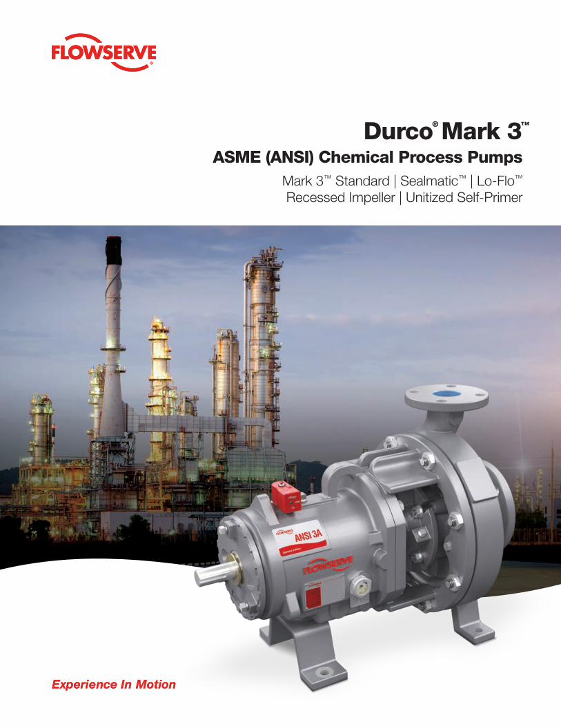
ASME (ANSI) Chemical Process PumpsMark 3™ Standard | Sealmatic™ | Lo-Flo™
Recessed Impeller | Unitized Self-Primer
Durco® Mark 3™
Experience In Motion

2 Flowserve.com
Durco Mark 3 — the premier name in ASME chemical process pumps
The Durco Mark 3 chemical process pump provides outstanding hydraulic performance, unrivaled reliability and low
total cost of ownership. Conforming to ASME (ANSI) B73.1, it incorporates many proven reliability- and performance-
enhancing features. The resultant benefits are:
• Renewable, high-efficiency performance over the life of the pump with the reverse vane impeller
• Optimal, predictable seal chamber pressures that are re-established after every impeller setting
• Maximal mechanical seal life due to an ideal seal environment created by the SealSentry™ seal chamber
• Robust shaft and bearing designs that minimize shaft deflection and extend mechanical seal and bearing life
• Fast and accurate impeller setting with the industry’s most innovative external impeller adjustment mechanism
• In-shop reverse vane impeller adjustment with the only pump that takes full advantage of the back pullout design
Durco Mark 3 ASME (ANSI) Chemical Process Pump 3
Breadth of pumping solutions
Durco Mark 3 ASME (ANSI) chemical process pumps are available in a wide range of configurations
to provide flexibility in countless applications throughout the worldwide infrastructure markets:
• Acid transfer
• Brine
• Chemical processing
• Petrochemical processing
• Corrosive services
• Food and beverage
processing
• Hydrocarbon processing
• Pharmaceuticals
• Mechanically sealed
• Dynamically sealed
• Sealless, magnetic drive
• Low-flow
• Self-priming
• Recessed impeller
Table of contents
Durco Mark 3 ASME chemical process pumps 4 – 5
Performance curves 6
Interchangeability 7
Power ends 8 – 9
Shafts and bearings 10 – 11
SealSentry seal chambers 12 – 13
Impellers 14 – 15
IPS Beacon™ 2 condition monitor 16
Materials of construction 17
Options 18 – 19
Baseplates 20 – 22
Polyshield polymer baseplate and foundation system 23
Durco Mark 3 Lo-Flo pump 24 – 25
Durco Mark 3 Sealmatic pump 26 – 27
Durco Mark 3 Unitized Self-Priming pump 28 – 29
Durco Mark 3 Recessed Impeller pump 30 – 31
Durco Mark 3 pump family 32 – 33
Complementary pumps 34
Lifecycle cost solutions 35
Typical applications

4 Flowserve.com
Operating parameters1
• Flows to 1700 m3/h (7500 US gpm)
• Heads to 300 m (990 ft)
• Pressures to 27 bar (400 psi)
• Temperatures from -73°C to 370°C (-100°F to 700°F)
• Discharge sizes from 25 to 200 mm (1 to 8 in)
30 sizes available
• 7 Group 1
• 16 Group 2
• 7 Group 3
Features and benefits
Reverse vane impeller is the only impeller design that
offers repeatable pump performance throughout the life
of the pump. Open impellers are available.
SealSentry™ seal chambers with flow modifiers extend
seal life and provide self-flushing capability.
External micrometer accurately sets impeller clearance
in 20 seconds, whether in the shop or in the field.
Largest shaft and bearing components in standard
ASME pumps reduce shaft deflection and vibration to
extend bearing life and improve reliability.
Back pullout design allows removal of rotating element
without removing casing, piping or motor.
Durco Mark 3 ASME chemical process pumps
Conforming to ASME (ANSI) B73.1 and incorporating many advanced design features, the rugged Mark 3 pump
provides unmatched performance and reliability while minimizing the total cost of ownership. It is CE marked and
compliant with applicable directives such as ATEX.
1 Higher flow rates are available with the Ducro Mark 3 Group 4 high-capacity process pump. See brochure PS-10-39 for details.
Durco Mark 3 ASME (ANSI) Chemical Process Pump 5
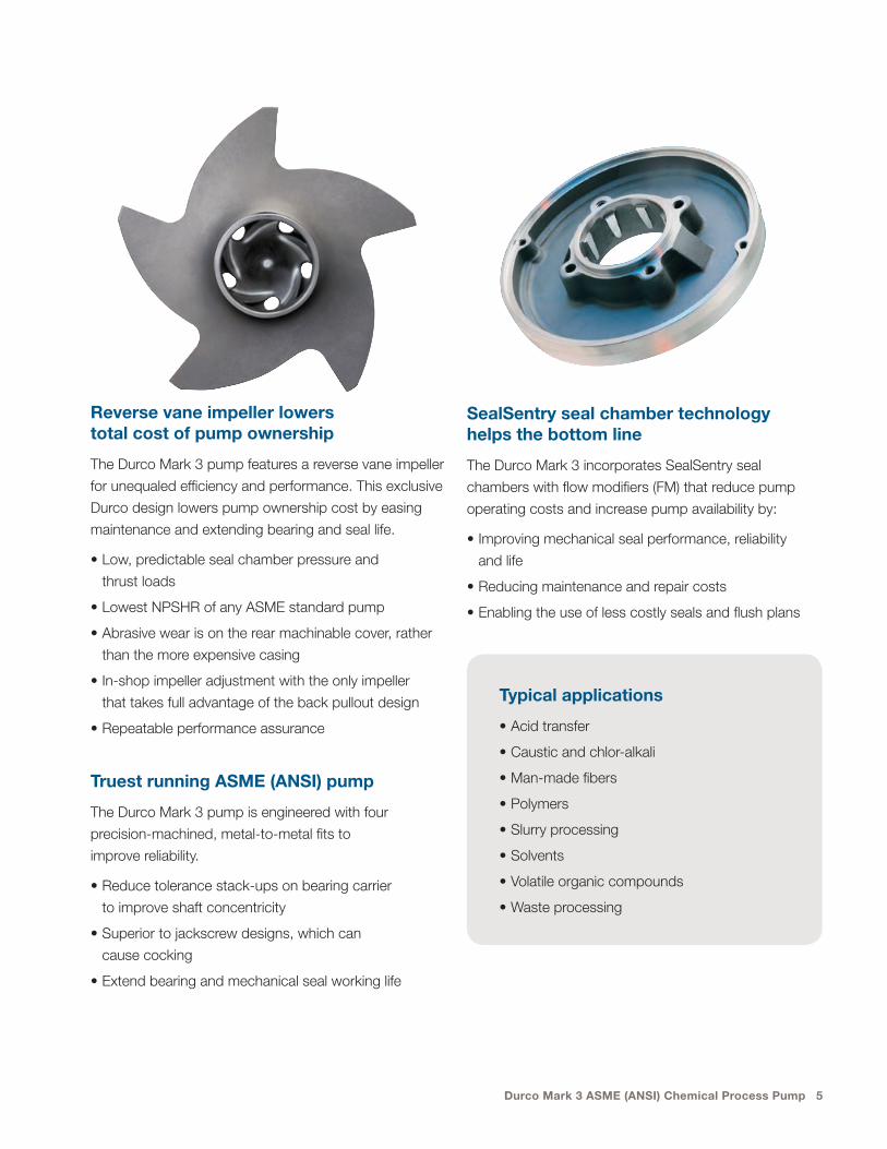
Reverse vane impeller lowers total cost of pump ownership
The Durco Mark 3 pump features a reverse vane impeller
for unequaled efficiency and performance. This exclusive
Durco design lowers pump ownership cost by easing
maintenance and extending bearing and seal life.
• Low, predictable seal chamber pressure and
thrust loads
• Lowest NPSHR of any ASME standard pump
• Abrasive wear is on the rear machinable cover, rather
than the more expensive casing
• In-shop impeller adjustment with the only impeller
that takes full advantage of the back pullout design
• Repeatable performance assurance
Truest running ASME (ANSI) pump
The Durco Mark 3 pump is engineered with four
precision-machined, metal-to-metal fits to
improve reliability.
• Reduce tolerance stack-ups on bearing carrier
to improve shaft concentricity
• Superior to jackscrew designs, which can
cause cocking
• Extend bearing and mechanical seal working life
SealSentry seal chamber technology helps the bottom line
The Durco Mark 3 incorporates SealSentry seal
chambers with flow modifiers (FM) that reduce pump
operating costs and increase pump availability by:
• Improving mechanical seal performance, reliability
and life
• Reducing maintenance and repair costs
• Enabling the use of less costly seals and flush plans
Typical applications
• Acid transfer
• Caustic and chlor-alkali
• Man-made fibers
• Polymers
• Slurry processing
• Solvents
• Volatile organic compounds
• Waste processing
6 Flowserve.com
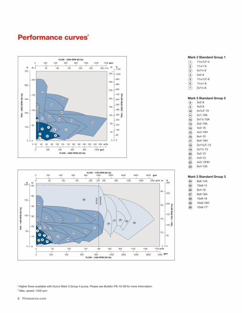
Performance curves2
m
80
60
40
20
0
ft300
250
200
150
100
50
0
TDH
– 1
750
RP
M (6
0 H
z)
ft200
150
100
50
0
m60
50
40
30
20
10
0
TDH
– 1
450
RP
M (5
0 H
z)
0 200 400 600 800 1000 2800 4600 6400 8200 gpm
0 50 100 150 200 227 400 800 1200 1600 2000 m3/h
3
FLOW – 1750 RPM (60 Hz)
0 50 100 150 190 500 800 1100 1400 1700 m3/h
0 200 400 600 800 2300 3800 5300 6800 2300 gpm FLOW – 1450 RPM (50 Hz)
SC
ALE
CH
AN
GE
1
2 4
9876
5
10
11 12 13
14
1516
17
21
22
23
26
19 20
18
2427 25 28
29
Mark 3 Standard Group 1 1½x1LF-4
1½x1-6
3x1½-6
3x2-6
1½x1LF-8
1½x1-8
3x1½-8
Mark 3 Standard Group 2 3x2-8
4x3-8
2x1LF-10
2x1-10A
3x1½-10A
3x2-10A
4x3-10
4x3-10H
6x4-10
6x4-10H
3x1½LF-13
3x1½-13
3x2-13
4x3-13
4x3-13HH
6x4-13A
Mark 3 Standard Group 3 8x6-14A
10x8-14
6x4-16
8x6-16A
10x8-16
10x8-16H
10x8-173
1
2
3
4
5
6
7
8
9
10
11
12
13
14
15
16
17
18
19
20
21
22
23
24
25
26
27
28
29
30
2 Higher flows available with Durco Mark 3 Group 4 pump. Please see Bulletin PS-10-39 for more information.3 Max. speed: 1450 rpm
0 20 40 60 80 100 120 140 160 180 200 220 240 260 m3/h
0 200 400 600 800 1000 gpm
ft
750
600
450
300
150
0
m
200
150
100
50
0
TD
H –
290
0 R
PM
(50
Hz)
0 200 400 600 800 1000 1200 1400 gpm
0 50 100 150 200 250 300 m3/h
1
23 4
9876
5
10
1112
1314
16
21
19
20
18
m
320
280
240
200
160
120
80
40
0
ft1120
1040
960
880
800
720
640
560
480
400
320
240
160
80
0
TD
H –
350
0 R
PM
(60
Hz)
FLOW – 3500 RPM (60 Hz)
FLOW – 2900 RPM (50 Hz)

Durco Mark 3 ASME (ANSI) Chemical Process Pump 7
InterchangeabilityWith only three different power frames and five SealSentry seal chamber options, the
30 pumps in the Durco Mark 3 family offer a high degree of parts interchangeability.
Pumps delivered worldwide are manufactured in ISO 9001 certified Flowserve facilities. Quality System Certificate
• • • • • • • • • • • • • • • • • • • • •
PO
WE
R E
ND
RE
AR
CO
VE
RS
RE
VE
RS
E V
AN
EIM
PE
LLE
RS
FRO
NT
VAN
E,
OP
EN
STY
LE
IMP
ELL
ER
S
CA
SIN
GS
1½x1LF-4
1½x1-6
3x1½-6
3x2-6
1½x1LF-8
1½x1-8
3x1½-8
OR
PO
WE
R E
ND
RE
AR
CO
VE
RS
AD
AP
TER
S
RE
VE
RS
E V
AN
EIM
PE
LLE
RS
FRO
NT
VAN
E,
OP
EN
STY
LE
IMP
ELL
ER
S
CA
SIN
GS
8x6-14A
10x8-14
6x4-16
8x6-16A
10x8-16
10x8-16H
10x8-17
OR
• • • • • • • • • • • • • • • • • • • • • • • • • • •
Mark 3 Standard Group 3
Mark 3 Standard Group 1
• • • • • • • • • • • • • • • • • • • • • • • • • • • • • • • • • • • • • • • • • • • • • • • • • • • •
PO
WE
R E
ND
RE
AR
CO
VE
RS
AD
AP
TER
S
RE
VE
RS
E V
AN
EIM
PE
LLE
RS
FRO
NT
VAN
E,
OP
EN
STY
LE
IMP
ELL
ER
S
CA
SIN
GS
3x2-8
4x3-8
2x1LF-10
2x1-10A
3x1½-10A
3x2-10A
4x3-10
4x3-10H
6x4-10
6x4-10H
3x1½LF-13
3x1½-13
3x2-13
4x3-13
4x3-13HH
6x4-13A
OR
Mark 3 Standard Group 2
8 Flowserve.com
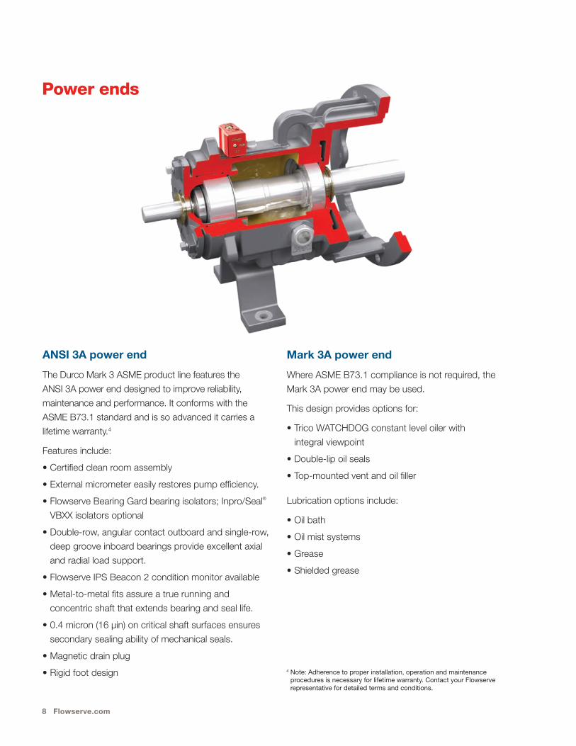
Power ends
ANSI 3A power end
The Durco Mark 3 ASME product line features the
ANSI 3A power end designed to improve reliability,
maintenance and performance. It conforms with the
ASME B73.1 standard and is so advanced it carries a
lifetime warranty.4
Features include:
• Certified clean room assembly
• External micrometer easily restores pump efficiency.
• Flowserve Bearing Gard bearing isolators; Inpro/Seal®
VBXX isolators optional
• Double-row, angular contact outboard and single-row,
deep groove inboard bearings provide excellent axial
and radial load support.
• Flowserve IPS Beacon 2 condition monitor available
• Metal-to-metal fits assure a true running and
concentric shaft that extends bearing and seal life.
• 0.4 micron (16 μin) on critical shaft surfaces ensures
secondary sealing ability of mechanical seals.
• Magnetic drain plug
• Rigid foot design
Mark 3A power end
Where ASME B73.1 compliance is not required, the
Mark 3A power end may be used.
This design provides options for:
• Trico WATCHDOG constant level oiler with
integral viewpoint
• Double-lip oil seals
• Top-mounted vent and oil filler
Lubrication options include:
• Oil bath
• Oil mist systems
• Grease
• Shielded grease
4 Note: Adherence to proper installation, operation and maintenance procedures is necessary for lifetime warranty. Contact your Flowserve representative for detailed terms and conditions.
Durco Mark 3 ASME (ANSI) Chemical Process Pump 9
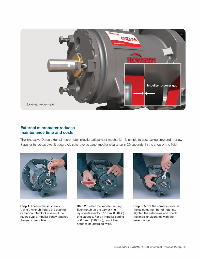
Impeller-to-cover gap
External micrometer reduces maintenance time and costs
The innovative Durco external micrometer impeller adjustment mechanism is simple to use, saving time and money.
Superior to jackscrews, it accurately sets reverse vane impeller clearance in 20 seconds, in the shop or the field.
Step 1: Loosen the setscrews. Using a wrench, rotate the bearing carrier counterclockwise until the reverse vane impeller lightly touches the rear cover plate.
Step 2: Select the impeller setting. Each notch on the carrier ring represents exactly 0.10 mm (0.004 in) of clearance. For an impeller setting of 0.5 mm (0.020 in), count five notches counterclockwise.
Step 3: Move the carrier clockwise the selected number of notches. Tighten the setscrews and check the impeller clearance with the feeler gauge.
External micrometer
10 Flowserve.com
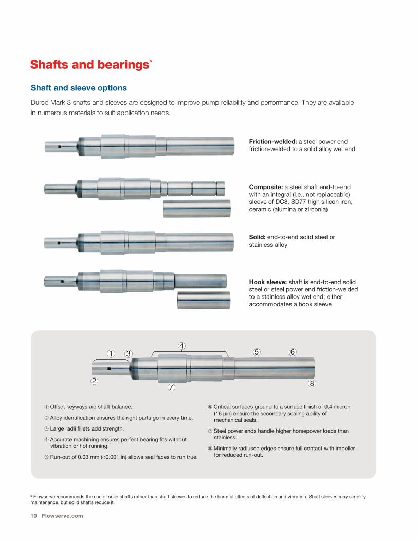
Shafts and bearings 5
Shaft and sleeve options
Durco Mark 3 shafts and sleeves are designed to improve pump reliability and performance. They are available
in numerous materials to suit application needs.
5 Flowserve recommends the use of solid shafts rather than shaft sleeves to reduce the harmful effects of deflec tion and vibra tion. Shaft sleeves may simplify main te nance, but solid shafts reduce it.
Friction-welded: a steel power end fric tion-welded to a solid alloy wet end
Composite: a steel shaft end-to-end with an integral (i.e., not replaceable) sleeve of DC8, SD77 high silicon iron, ceramic (alumina or zirconia)
Solid: end-to-end solid steel or stainless alloy
Hook sleeve: shaft is end-to-end solid steel or steel power end friction-welded to a stainless alloy wet end; either accommodates a hook sleeve
➀ Offset keyways aid shaft balance.
➁ Alloy identification ensures the right parts go in every time.
➂ Large radii fillets add strength.
➃ Accurate machining ensures perfect bearing fits without vibration or hot running.
➄ Run-out of 0.03 mm (<0.001 in) allows seal faces to run true.
➅ Critical surfaces ground to a sur face finish of 0.4 micron (16 µin) ensure the secondary sealing ability of mechanical seals.
➆ Steel power ends handle higher horse power loads than stainless.
➇ Minimally radiused edges ensure full contact with impeller for reduced run-out.
1 3
27
5 6
8
4
Durco Mark 3 ASME (ANSI) Chemical Process Pump 11
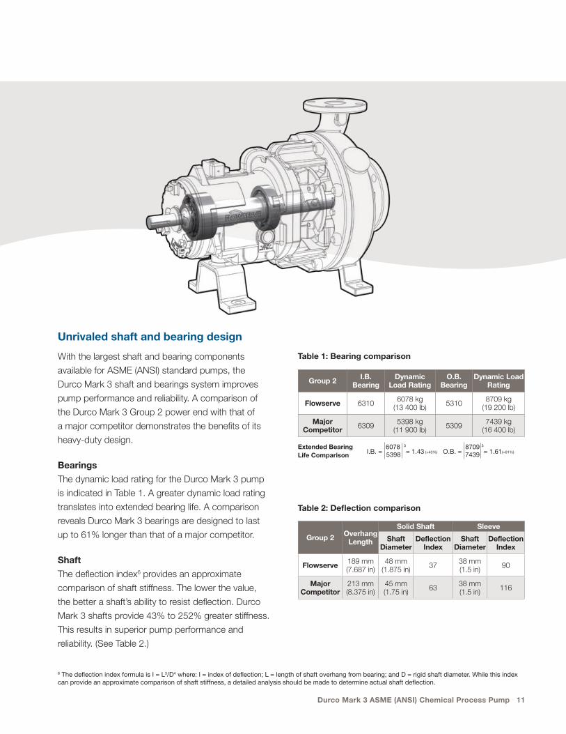
Unrivaled shaft and bearing design
With the largest shaft and bearing components
available for ASME (ANSI) standard pumps, the
Durco Mark 3 shaft and bearings system improves
pump performance and reliability. A comparison of
the Durco Mark 3 Group 2 power end with that of
a major competitor demonstrates the benefits of its
heavy-duty design.
Bearings
The dynamic load rating for the Durco Mark 3 pump
is indicated in Table 1. A greater dynamic load rating
translates into extended bearing life. A comparison
reveals Durco Mark 3 bearings are designed to last
up to 61% longer than that of a major competitor.
Shaft
The deflection index6 provides an approximate
comparison of shaft stiffness. The lower the value,
the better a shaft’s ability to resist deflection. Durco
Mark 3 shafts provide 43% to 252% greater stiffness.
This results in superior pump performance and
reliability. (See Table 2.)
6 The deflection index formula is I = L3/D4 where: I = index of deflection; L = length of shaft overhang from bearing; and D = rigid shaft diameter. While this index can provide an approximate comparison of shaft stiffness, a detailed analysis should be made to determine actual shaft deflection.
O.B. = 8709 3
= 1.61(+61%) 7439I.B. = 6078 3
= 1.43 (+43%) 5398Extended Bearing Life Comparison
Table 1: Bearing comparison
Table 2: Deflection comparison
Group 2 I.B. Bearing
Dynamic Load Rating
O.B. Bearing
Dynamic Load Rating
Flowserve 6310 6078 kg (13 400 lb) 5310 8709 kg
(19 200 lb)
Major Competitor 6309 5398 kg
(11 900 lb) 5309 7439 kg (16 400 lb)
Group 2 Overhang Length
Solid Shaft Sleeve
Shaft Diameter
Deflection Index
Shaft Diameter
Deflection Index
Flowserve 189 mm (7.687 in)
48 mm (1.875 in) 37 38 mm
(1.5 in) 90
Major Competitor
213 mm (8.375 in)
45 mm (1.75 in) 63 38 mm
(1.5 in) 116

12 Flowserve.com
SealSentry seal chambers
Advanced seal chamber technology
An intergral part of the real cover, Durco SealSentry seal
chambers extend seal life, improve pump reliability, and
reduce the total cost of pump ownership:
• Provide optimal seal chamber environment
• Extend mechanical seal life
– Self-flushing
– Self-venting
– Self-draining
• Reduce maintenance and repair costs
• Permit use of less expensive seals and flush plans;
plans 11, 32, 52, 53, etc. can be eliminated
• Provide a safer environment for personnel
Flow modifiers extend seal life
• Flow modifiers redirect flow from circumferential to axial.
• Balanced flow with low-pressure drop in the chamber
helps keep solids in suspension, minimizing erosion.
• The mechanical seal creates a centrifuging action
away from its parts.
• Solids and slurry merge into the returning flow
path and are flushed out of the seal chamber.
Jacketed rear covers available
Jacketed versions of Durco rear covers with SealSentry
seal chambers are available. Flowserve engineers
will help you select the right jacketed cover for your
application.
Durco Mark 3 ASME (ANSI) Chemical Process Pump 13
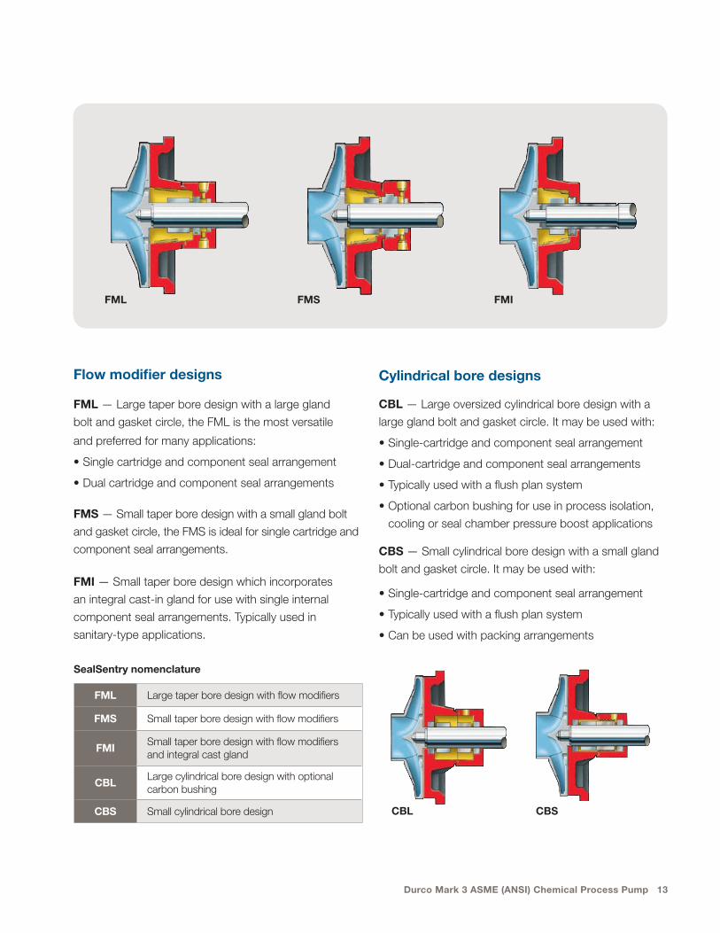
Cylindrical bore designs
CBL — Large oversized cylindrical bore design with a
large gland bolt and gasket circle. It may be used with:
• Single-cartridge and component seal arrangement
• Dual-cartridge and component seal arrangements
• Typically used with a flush plan system
• Optional carbon bushing for use in process isolation,
cooling or seal chamber pressure boost applications
CBS — Small cylindrical bore design with a small gland
bolt and gasket circle. It may be used with:
• Single-cartridge and component seal arrangement
• Typically used with a flush plan system
• Can be used with packing arrangements
Flow modifier designs
FML — Large taper bore design with a large gland
bolt and gasket circle, the FML is the most versatile
and preferred for many applications:
• Single cartridge and component seal arrangement
• Dual cartridge and component seal arrangements
FMS — Small taper bore design with a small gland bolt
and gasket circle, the FMS is ideal for single cartridge and
component seal arrangements.
FMI — Small taper bore design which incorporates
an integral cast-in gland for use with single internal
component seal arrangements. Typically used in
sanitary-type applications.
FML Large taper bore design with flow modifiers
FMS Small taper bore design with flow modifiers
FMISmall taper bore design with flow modifiers and integral cast gland
CBLLarge cylindrical bore design with optional carbon bushing
CBS Small cylindrical bore design
SealSentry nomenclature
FML FMS FMI
CBL CBS
14 Flowserve.com
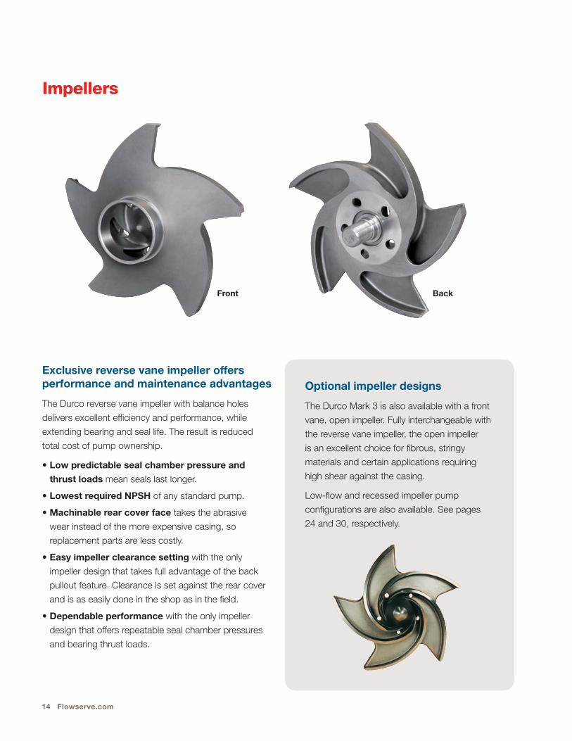
Impellers
Exclusive reverse vane impeller offers performance and maintenance advantages
The Durco reverse vane impeller with balance holes
delivers excellent efficiency and performance, while
extending bearing and seal life. The result is reduced
total cost of pump ownership.
• Low predictable seal chamber pressure and
thrust loads mean seals last longer.
• Lowest required NPSH of any standard pump.
• Machinable rear cover face takes the abrasive
wear instead of the more expensive casing, so
replacement parts are less costly.
• Easy impeller clearance setting with the only
impeller design that takes full advantage of the back
pullout feature. Clearance is set against the rear cover
and is as easily done in the shop as in the field.
• Dependable performance with the only impeller
design that offers repeatable seal chamber pressures
and bearing thrust loads.
Optional impeller designs
The Durco Mark 3 is also available with a front
vane, open impeller. Fully interchangeable with
the reverse vane impeller, the open impeller
is an excellent choice for fibrous, stringy
materials and certain applications requiring
high shear against the casing.
Low-flow and recessed impeller pump
configurations are also available. See pages
24 and 30, respectively.
Front Back
Durco Mark 3 ASME (ANSI) Chemical Process Pump 15
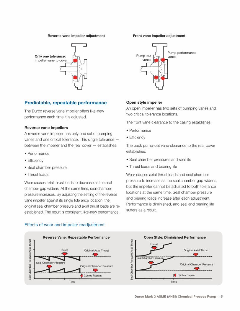
Open style impeller
An open impeller has two sets of pumping vanes and
two critical tolerance locations.
The front vane clearance to the casing establishes:
• Performance
• Efficiency
The back pump-out vane clearance to the rear cover
establishes:
• Seal chamber pressures and seal life
• Thrust loads and bearing life
Wear causes axial thrust loads and seal chamber
pressure to increase as the seal chamber gap widens,
but the impeller cannot be adjusted to both tolerance
locations at the same time. Seal chamber pressure
and bearing loads increase after each adjustment.
Performance is diminished, and seal and bearing life
suffers as a result.
Predictable, repeatable performance
The Durco reverse vane impeller offers like-new
performance each time it is adjusted.
Reverse vane impellers
A reverse vane impeller has only one set of pumping
vanes and one critical tolerance. This single tolerance —
between the impeller and the rear cover — establishes:
• Performance
• Efficiency
• Seal chamber pressure
• Thrust loads
Wear causes axial thrust loads to decrease as the seal
chamber gap widens. At the same time, seal chamber
pressure increases. By adjusting the setting of the reverse
vane impeller against its single tolerance location, the
original seal chamber pressure and axial thrust loads are re-
established. The result is consistent, like-new performance.
Sea
l Cha
mb
er P
ress
ure/
Axi
al T
hrus
t Reverse Vane: Repeatable Performance
Time
Thrust Original Axial Thrust
Seal Chamber PressureOriginal Chamber Pressure
Cycles Repeat
Sea
l Cha
mb
er P
ress
ure/
Axi
al T
hrus
t Open Style: Diminished Performance
Time
Thrust
Original Axial Thrust
Seal Chamber Pressure
Original Chamber Pressure
Cycles Repeat
Effects of wear and impeller readjustment
Front vane impeller adjustment
Pump-out vanes
Reverse vane impeller adjustment
Only one tolerance: impeller vane to cover
Pump performance vanes
16 Flowserve.com
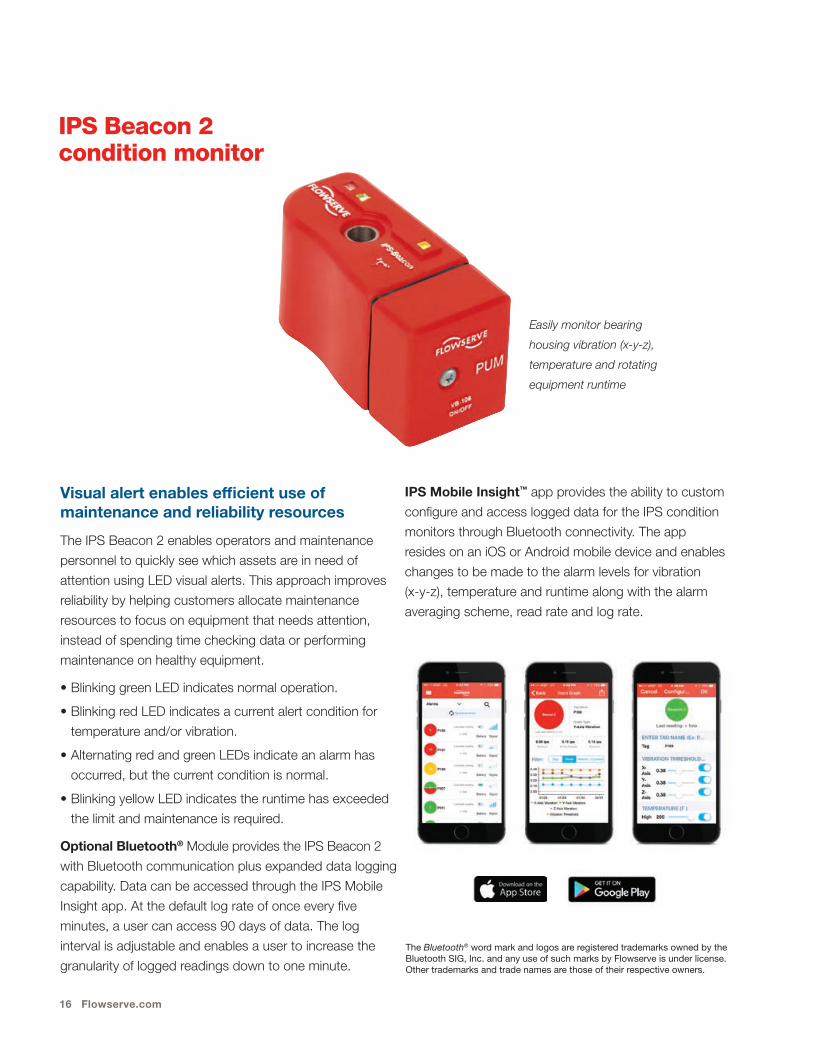
IPS Beacon 2 condition monitor
Visual alert enables efficient use of maintenance and reliability resources
The IPS Beacon 2 enables operators and maintenance
personnel to quickly see which assets are in need of
attention using LED visual alerts. This approach improves
reliability by helping customers allocate maintenance
resources to focus on equipment that needs attention,
instead of spending time checking data or performing
maintenance on healthy equipment.
• Blinking green LED indicates normal operation.
• Blinking red LED indicates a current alert condition for
temperature and/or vibration.
• Alternating red and green LEDs indicate an alarm has
occurred, but the current condition is normal.
• Blinking yellow LED indicates the runtime has exceeded
the limit and maintenance is required.
Optional Bluetooth® Module provides the IPS Beacon 2
with Bluetooth communication plus expanded data logging
capability. Data can be accessed through the IPS Mobile
Insight app. At the default log rate of once every five
minutes, a user can access 90 days of data. The log
interval is adjustable and enables a user to increase the
granularity of logged readings down to one minute.
IPS Mobile Insight™ app provides the ability to custom
configure and access logged data for the IPS condition
monitors through Bluetooth connectivity. The app
resides on an iOS or Android mobile device and enables
changes to be made to the alarm levels for vibration
(x-y-z), temperature and runtime along with the alarm
averaging scheme, read rate and log rate.
The Bluetooth® word mark and logos are registered trademarks owned by the Bluetooth SIG, Inc. and any use of such marks by Flowserve is under license. Other trademarks and trade names are those of their respective owners.
Easily monitor bearing
housing vibration (x-y-z),
temperature and rotating
equipment runtime

Durco Mark 3 ASME (ANSI) Chemical Process Pump 17
Materials of construction
Standard materials of construction7
All Durco Mark 3 wet-end castings carry a limited lifetime guarantee.
D esignation Symbol ACI Designation Equivalent Wrought Designation ASTM Specifications
Ductile iron DCI None None A395, Gr. 60-40-18
Carbon steel DS None Carbon steel A216 Gr. WCB
CF-8M D4 CF8M 316 A744, Gr. CF8M
CF-3M D4L CF3M 316L A744, Gr. CF3M
Durcomet™ 100 CD4M CD4MCuN Ferralium 255 A995, Gr. 1B
Super Duplex (5A) 5A CE3MN 2507 A890 Gr. 5A
Super Duplex (6A) 6A CD3MWCuN Zeron 100 A890 Gr. 6A
Durimet 20 D20 CN7M Alloy 20 A744, Gr. CN7M
Chlorimet 2 DC2 N7M Alloy B-2 A494, Gr. N7M
Chlorimet 3 DC3 CW6M Alloy C-276 A494, Gr. CW6M
Titanium Ti None Titanium, Grade 3 B367, Gr. C-3
Titanium-Pd Ti-Pd None Titanium, Grade 7 or 8 B367, Gr. C-8A
Monel DM M35-1 Monel 400 A494, Gr. M35-1
Nickel DNI CZ100 Nickel 200 A494, Gr. CZ100
Durcomet 5 DV None Antimit A611 None
CY-40 DINC CY40 Inconel 600 A494, Gr. CY40
Superchlor® SD77 None None None
DC-8 DC8 None None None
Zirconium Zr None Zirconium B752, Gr. 705C
7 Alloys conform to the chemical and mechanical requirements of the latest edition of the ASTM specification.
18 Flowserve.com
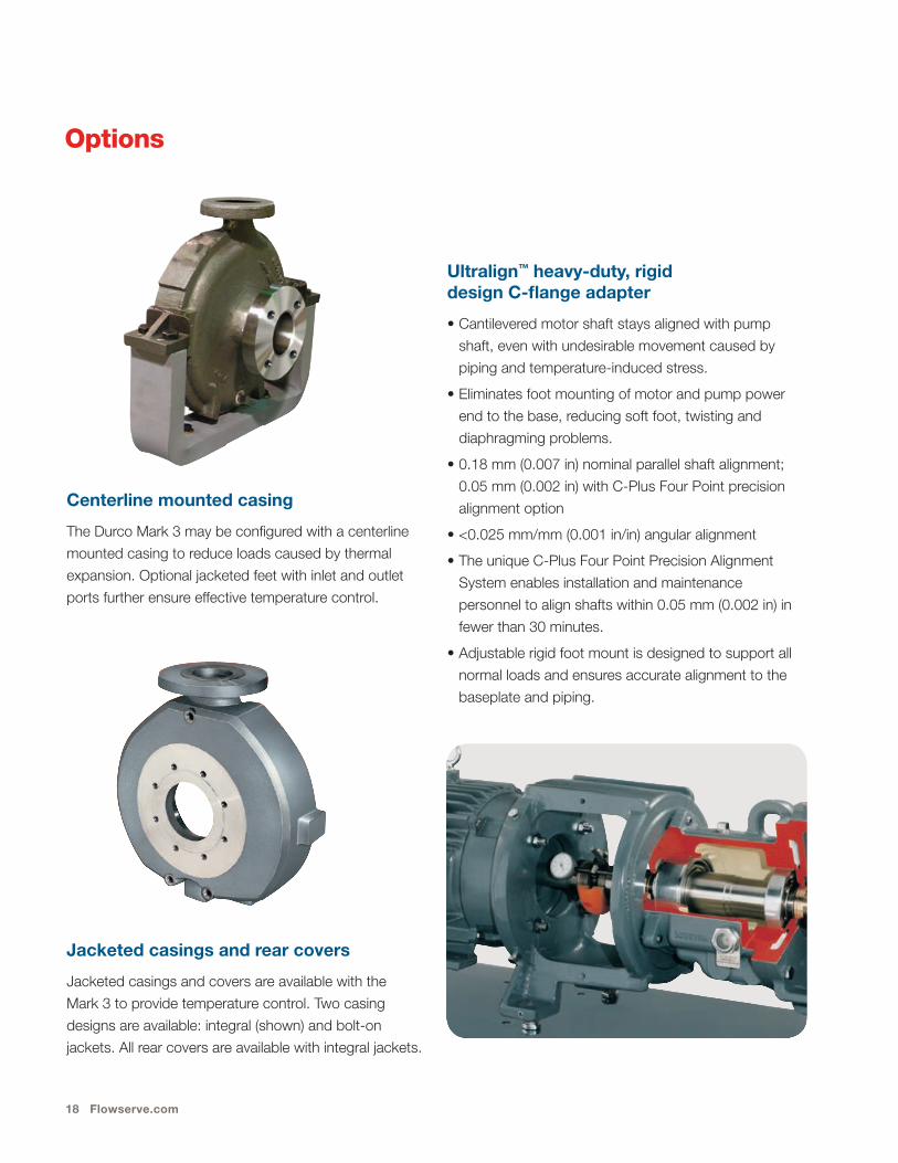
Centerline mounted casing
The Durco Mark 3 may be configured with a centerline
mounted casing to reduce loads caused by thermal
expansion. Optional jacketed feet with inlet and outlet
ports further ensure effective temperature control.
Options
Ultralign™ heavy-duty, rigid design C-flange adapter
• Cantilevered motor shaft stays aligned with pump
shaft, even with undesirable movement caused by
piping and temperature-induced stress.
• Eliminates foot mounting of motor and pump power
end to the base, reducing soft foot, twisting and
diaphragming problems.
• 0.18 mm (0.007 in) nominal parallel shaft alignment;
0.05 mm (0.002 in) with C-Plus Four Point precision
alignment option
• <0.025 mm/mm (0.001 in/in) angular alignment
• The unique C-Plus Four Point Precision Alignment
System enables installation and maintenance
personnel to align shafts within 0.05 mm (0.002 in) in
fewer than 30 minutes.
• Adjustable rigid foot mount is designed to support all
normal loads and ensures accurate alignment to the
baseplate and piping.
Jacketed casings and rear covers
Jacketed casings and covers are available with the
Mark 3 to provide temperature control. Two casing
designs are available: integral (shown) and bolt-on
jackets. All rear covers are available with integral jackets.
Durco Mark 3 ASME (ANSI) Chemical Process Pump 19
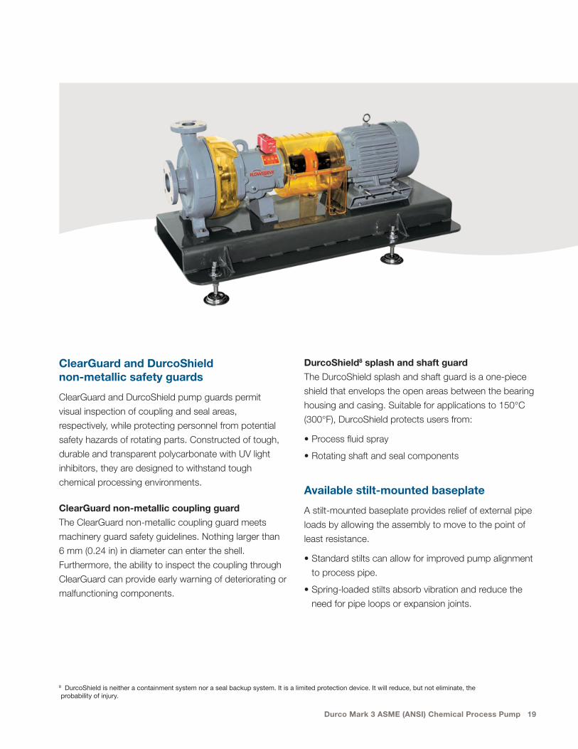
ClearGuard and DurcoShield non-metallic safety guards
ClearGuard and DurcoShield pump guards permit
visual inspection of coupling and seal areas,
respectively, while protecting personnel from potential
safety hazards of rotating parts. Constructed of tough,
durable and transparent polycarbonate with UV light
inhibitors, they are designed to withstand tough
chemical processing environments.
ClearGuard non-metallic coupling guard
The ClearGuard non-metallic coupling guard meets
machinery guard safety guidelines. Nothing larger than
6 mm (0.24 in) in diameter can enter the shell.
Furthermore, the ability to inspect the coupling through
ClearGuard can provide early warning of deteriorating or
malfunctioning components.
8 DurcoShield is neither a containment system nor a seal backup system. It is a limited protection device. It will reduce, but not eliminate, the probability of injury.
DurcoShield8 splash and shaft guard
The DurcoShield splash and shaft guard is a one-piece
shield that envelops the open areas between the bearing
housing and casing. Suitable for applications to 150°C
(300°F), DurcoShield protects users from:
• Process fluid spray
• Rotating shaft and seal components
Available stilt-mounted baseplate
A stilt-mounted baseplate provides relief of external pipe
loads by allowing the assembly to move to the point of
least resistance.
• Standard stilts can allow for improved pump alignment
to process pipe.
• Spring-loaded stilts absorb vibration and reduce the
need for pipe loops or expansion joints.
20 Flowserve.com
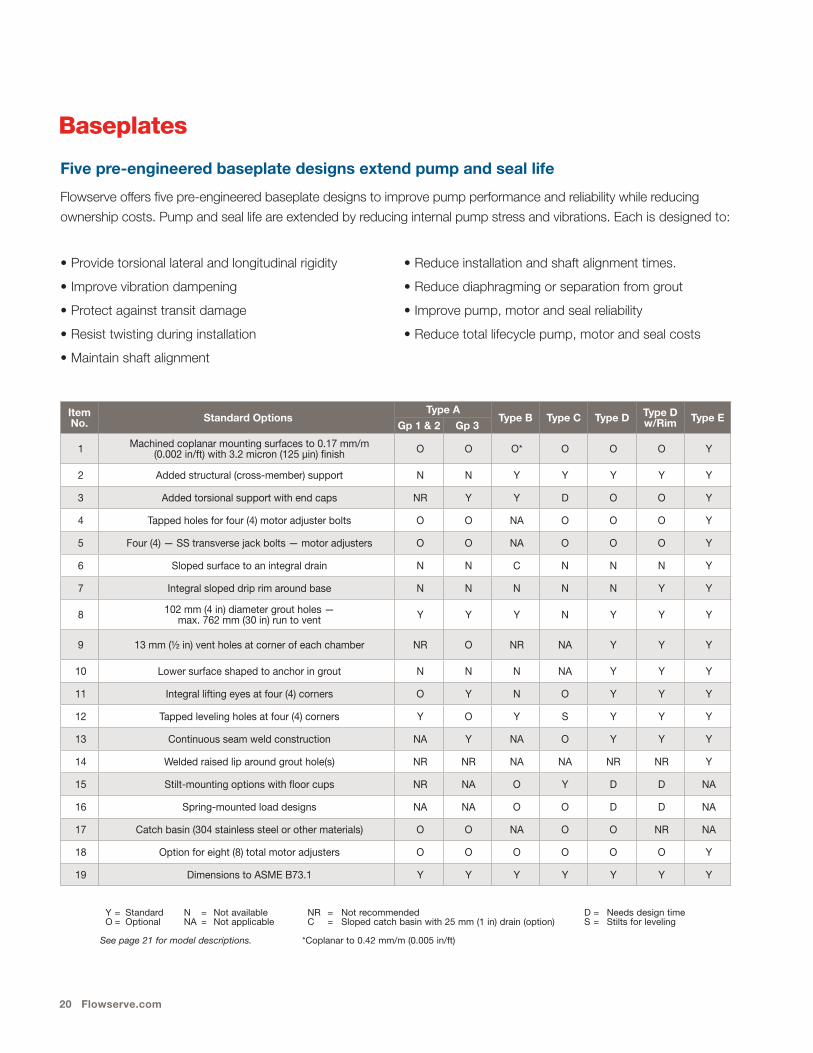
Baseplates
Five pre-engineered baseplate designs extend pump and seal life
Flowserve offers five pre-engineered baseplate designs to improve pump performance and reliability while reducing
ownership costs. Pump and seal life are extended by reducing internal pump stress and vibrations. Each is designed to:
Item No. Standard Options
Type AType B Type C Type D Type D
w/Rim Type EGp 1 & 2 Gp 3
1 Machined coplanar mounting surfaces to 0.17 mm/m (0.002 in/ft) with 3.2 micron (125 µin) finish O O O* O O O Y
2 Added structural (cross-member) support N N Y Y Y Y Y
3 Added torsional support with end caps NR Y Y D O O Y
4 Tapped holes for four (4) motor adjuster bolts O O NA O O O Y
5 Four (4) — SS transverse jack bolts — motor adjusters O O NA O O O Y
6 Sloped surface to an integral drain N N C N N N Y
7 Integral sloped drip rim around base N N N N N Y Y
8 102 mm (4 in) diameter grout holes — max. 762 mm (30 in) run to vent Y Y Y N Y Y Y
9 13 mm (½ in) vent holes at corner of each chamber NR O NR NA Y Y Y
10 Lower surface shaped to anchor in grout N N N NA Y Y Y
11 Integral lifting eyes at four (4) corners O Y N O Y Y Y
12 Tapped leveling holes at four (4) corners Y O Y S Y Y Y
13 Continuous seam weld construction NA Y NA O Y Y Y
14 Welded raised lip around grout hole(s) NR NR NA NA NR NR Y
15 Stilt-mounting options with floor cups NR NA O Y D D NA
16 Spring-mounted load designs NA NA O O D D NA
17 Catch basin (304 stainless steel or other materials) O O NA O O NR NA
18 Option for eight (8) total motor adjusters O O O O O O Y
19 Dimensions to ASME B73.1 Y Y Y Y Y Y Y
Y = Standard N = Not available NR = Not recommended D = Needs design timeO = Optional NA = Not applicable C = Sloped catch basin with 25 mm (1 in) drain (option) S = Stilts for leveling
See page 21 for model descriptions. *Coplanar to 0.42 mm/m (0.005 in/ft)
• Provide torsional lateral and longitudinal rigidity
• Improve vibration dampening
• Protect against transit damage
• Resist twisting during installation
• Maintain shaft alignment
• Reduce installation and shaft alignment times.
• Reduce diaphragming or separation from grout
• Improve pump, motor and seal reliability
• Reduce total lifecycle pump, motor and seal costs

Durco Mark 3 ASME (ANSI) Chemical Process Pump 21
Rigid construction
Metal baseplate sizes:
• 139 to 258 feature 12 mm (1⁄2 in) steel plate
• 264 to 280 feature 16 mm (5⁄8 in) steel plate
• 368 to 398 feature 19 mm (3⁄4 in) steel plate
Polybase baseplates are constructed of 76 to
102 mm (3 to 4 in) solid polymer concrete.
Types B, C, D and E are reinforced with added
structural support for improved rigidity.
Type A Standard ASME (ANSI) baseplate; foundation mounted
Type B Polybase™; foundation or stilt mounted
Type C Reinforced; stilt mounted
Type D Reinforced; foundation mounted; drip rim optional
Type E Heavy-duty, foundation mounted; complies with PIP RESP 002

22 Flowserve.com
Polymer concrete baseplate offers impressive benefits:
• Low installed cost
• Superior vibration damping
• Corrosion resistance
• Superior resistance to twisting or diaphragming
• Optional catch basin and grout holes
• Inserts available for alternate equip ment
con figuration requirements
Baseplates are fundamental to extending pump life
The test stand provides three-corner support of the
ungrouted base plates. The addition of weights on the
unsupported fourth corner caused baseplate distor tion.
This distortion resulted in measurable shaft move ment
that can cause problems with field instal lations and
nega tively affect pump reliability and life.
The twist test is a means of comparing rigid base plate
designs. Correct ly installed rigid baseplates should not
experience these twist effects. For more infor ma tion
about the results of base plate test ing, contact your local
Flowserve sales representative.
Baseplate rigidity test — twist mode
Maximum parallel shaft deflection at applied force
Vibration damping of polymer concrete versus cast iron
© John F. Kane, Composites Institute, The Society of the Plastics Industry, Inc.
Cast Iron — 0.125 sec.
Polymer Concrete — 0.125 sec.
0.070 (1.78)
0.060 (1.52)
0.050 (1.27)
0.040 (1.02)
0.030 (0.08)
0.020 (0.51)
0.010 (0.25)
0.000 (0.00) 0 100 200 (45) (91)
Load – lb (kg)
Def
lect
ion
– in
ch (m
m)
A
D
E
BC
Type A 0.022 in (0.56 mm)
Type B 0.004 in (0.01 mm)
Type C 0.003 in (0.08 mm)
Type D 0.016 in (0.41 mm)
Type E 0.005 in (0.13 mm)
Durco Mark 3 ASME (ANSI) Chemical Process Pump 23
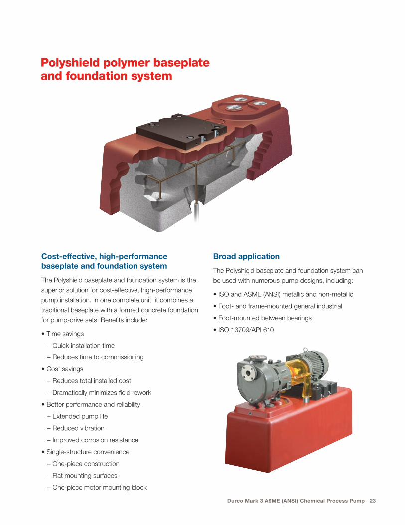
Polyshield polymer baseplate and foundation system
Cost-effective, high-performance baseplate and foundation system
The Polyshield baseplate and foundation system is the
superior solution for cost-effective, high-performance
pump installation. In one complete unit, it combines a
traditional baseplate with a formed concrete foundation
for pump-drive sets. Benefits include:
• Time savings
– Quick installation time
– Reduces time to commissioning
• Cost savings
– Reduces total installed cost
– Dramatically minimizes field rework
• Better performance and reliability
– Extended pump life
– Reduced vibration
– Improved corrosion resistance
• Single-structure convenience
– One-piece construction
– Flat mounting surfaces
– One-piece motor mounting block
Broad application
The Polyshield baseplate and foundation system can
be used with numerous pump designs, including:
• ISO and ASME (ANSI) metallic and non-metallic
• Foot- and frame-mounted general industrial
• Foot-mounted between bearings
• ISO 13709/API 610
24 Flowserve.com
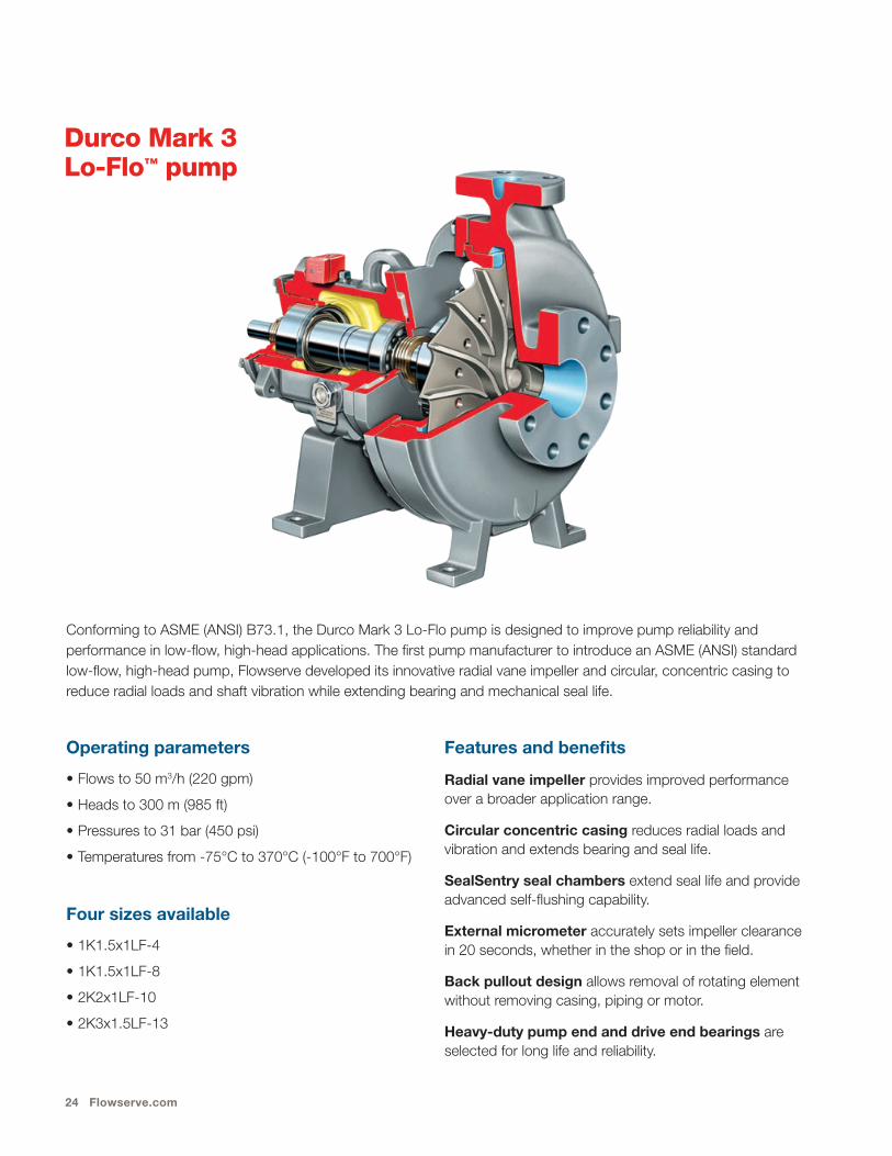
Durco Mark 3 Lo-Flo™ pump
Operating parameters
• Flows to 50 m3/h (220 gpm)
• Heads to 300 m (985 ft)
• Pressures to 31 bar (450 psi)
• Temperatures from -75°C to 370°C (-100°F to 700°F)
Four sizes available
• 1K1.5x1LF-4
• 1K1.5x1LF-8
• 2K2x1LF-10
• 2K3x1.5LF-13
Features and benefits
Radial vane impeller provides improved performance over a broader application range.
Circular concentric casing reduces radial loads and vibration and extends bearing and seal life.
SealSentry seal chambers extend seal life and provide advanced self-flushing capability.
External micrometer accurately sets impeller clearance in 20 seconds, whether in the shop or in the field.
Back pullout design allows removal of rotating element without removing casing, piping or motor.
Heavy-duty pump end and drive end bearings are selected for long life and reliability.
Conforming to ASME (ANSI) B73.1, the Durco Mark 3 Lo-Flo pump is designed to improve pump reliability and performance in low-flow, high-head applications. The first pump manufacturer to introduce an ASME (ANSI) standard low-flow, high-head pump, Flowserve developed its innovative radial vane impeller and circular, concentric casing to reduce radial loads and shaft vibration while extending bearing and mechanical seal life.
Durco Mark 3 ASME (ANSI) Chemical Process Pump 25
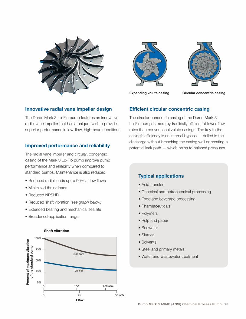
Innovative radial vane impeller design
The Durco Mark 3 Lo-Flo pump features an innovative
radial vane impeller that has a unique twist to provide
superior performance in low-flow, high-head conditions.
Improved performance and reliability
The radial vane impeller and circular, concentric
casing of the Mark 3 Lo-Flo pump improve pump
performance and reliability when compared to
standard pumps. Maintenance is also reduced.
• Reduced radial loads up to 90% at low flows
• Minimized thrust loads
• Reduced NPSHR
• Reduced shaft vibration (see graph below)
• Extended bearing and mechanical seal life
• Broadened application range
Per
cent
of
max
imum
vib
rati
on
of
the
stan
dar
d p
ump
0 100 200
0 25 50
Lo-Flo
Standard
Flow
100%
75%
50%
25%
0%gpm
m3/h
Shaft vibration
Expanding volute casing Circular concentric casing
Typical applications
• Acid transfer
• Chemical and petrochemical processing
• Food and beverage processing
• Pharmaceuticals
• Polymers
• Pulp and paper
• Seawater
• Slurries
• Solvents
• Steel and primary metals
• Water and wastewater treatment
Efficient circular concentric casing
The circular concentric casing of the Durco Mark 3
Lo-Flo pump is more hydraulically efficient at lower flow
rates than conventional volute casings. The key to the
casing’s efficiency is an internal bypass — drilled in the
discharge without breaching the casing wall or creating a
potential leak path — which helps to balance pressures.
26 Flowserve.com
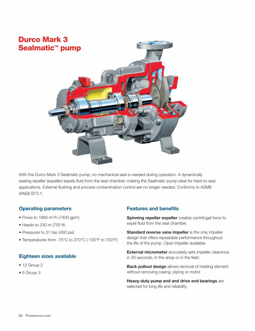
Durco Mark 3 Sealmatic™ pump
Operating parameters
• Flows to 1680 m3/h (7400 gpm)
• Heads to 230 m (755 ft)
• Pressures to 31 bar (450 psi)
• Temperatures from -75°C to 370°C (-100°F to 700°F)
Eighteen sizes available
• 12 Group 2
• 6 Group 3
With the Durco Mark 3 Sealmatic pump, no mechanical seal is needed during operation. A dynamically
sealing repeller (expeller) expels fluid from the seal chamber, making the Sealmatic pump ideal for hard-to-seal
applications. External flushing and process contamination control are no longer needed. Conforms to ASME
(ANSI) B73.1.
Features and benefits
Spinning repeller expeller creates centrifugal force to expel fluid from the seal chamber.
Standard reverse vane impeller is the only impeller design that offers repeatable performance throughout the life of the pump. Open impeller available.
External micrometer accurately sets impeller clearance in 20 seconds, in the shop or in the field.
Back pullout design allows removal of rotating element without removing casing, piping or motor.
Heavy-duty pump end and drive end bearings are selected for long life and reliability.
Durco Mark 3 ASME (ANSI) Chemical Process Pump 27
Choice of static sealing options
For positive sealing while the pump is stopped,
Flowserve offers a choice of low-cost alternatives
to mechanical seals, including:
• Self-lubricating, flexible graphite packing
• The FXP stationary fluoropolymer disk seal
• Dry-running, end-face seal
• Elastomeric lip seals
These static sealing options have the additional benefit
of not requiring external flush.
Dynamically sealing repeller
The Durco Mark 3 Sealmatic pump is equipped with a
dynamically sealing repeller. This technology enables
users to significantly reduce pump lifecycle costs in
demanding applications by eliminating the needs for:
• Conventional mechanical
seals and their associated
maintenance costs
• External flush and the
associated product dilution
• Contamination control
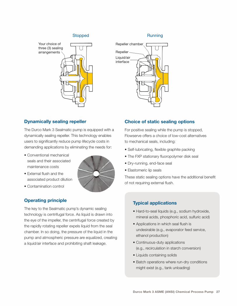
Operating principle
The key to the Sealmatic pump’s dynamic sealing
technology is centrifugal force. As liquid is drawn into
the eye of the impeller, the centrifugal force created by
the rapidly rotating repeller expels liquid from the seal
chamber. In so doing, the pressure of the liquid in the
pump and atmospheric pressure are equalized, creating
a liquid/air interface and prohibiting shaft leakage.
Your choice of three (3) sealing arrangements
Repeller chamber
Liquid/air interface
Repeller
RunningStopped
Typical applications
• Hard-to-seal liquids (e.g., sodium hydroxide,
mineral acids, phosphoric acid, sulfuric acid)
• Applications in which seal flush is
undesirable (e.g., evaporator feed service,
ethanol production)
• Continuous-duty applications
(e.g., recirculation in starch conversion)
• Liquids containing solids
• Batch operations where run-dry conditions
might exist (e.g., tank unloading)
28 Flowserve.com
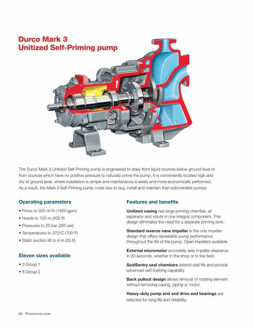
Durco Mark 3 Unitized Self-Priming pump
Operating parameters
• Flows to 320 m3/h (1400 gpm)
• Heads to 120 m (400 ft)
• Pressures to 20 bar (285 psi)
• Temperatures to 370°C (700°F)
• Static suction lift to 6 m (20 ft)
Eleven sizes available
• 3 Group 1
• 8 Group 2
Features and benefits
Unitized casing has large priming chamber, air separator and volute in one integral component. This design eliminates the need for a separate priming tank.
Standard reverse vane impeller is the only impeller design that offers repeatable pump performance throughout the life of the pump. Open impellers available.
External micrometer accurately sets impeller clearance in 20 seconds, whether in the shop or in the field.
SealSentry seal chambers extend seal life and provide advanced self-flushing capability.
Back pullout design allows removal of rotating element without removing casing, piping or motor.
Heavy-duty pump end and drive end bearings are
selected for long life and reliability.
The Durco Mark 3 Unitized Self-Priming pump is engineered to draw from liquid sources below ground level or
from sources which have no positive pressure to naturally prime the pump. It is conveniently located high and
dry at ground level, where installation is simple and maintenance is easily and more economically performed.
As a result, the Mark 3 Self-Priming pump costs less to buy, install and maintain than submersible pumps.

Durco Mark 3 ASME (ANSI) Chemical Process Pump 29
The priming principle
The Durco Mark 3 Unitized Self-Priming pump uses
liquid recirculation to prime the pump. The pressure
differential between the aerated liquid at the impeller and
the non-aerated liquid in the priming chamber creates
a vacuum that pulls liquid up the pipe. As a result, the
Durco Mark 3 Unitized Self-Priming pump is ideal for
suction lift applications or for pumping liquids with air
or gas phases.
Benefits of the Mark 3 Unitized Self-Priming pump
• Eliminates internal valves
• Eliminates external priming devices or foot-valves
• Portable
• Compact
• Easy to install
• Easy to maintain
Compact design
The Mark 3 Self-Priming pump’s compact design
enables it to fit in tight clearance locations. It also can
be mounted on a trailer for transportation to various
pumping areas, such as for wastewater lagoon service.
Typical applications
• Sump service
• Tank car unloading
• Duplex pumping lift station
• Fly ash pond transfer
• Waste acid transfer
• Waste treatment lagoon service
Initial prime and priming chamber
Pump startup and priming
Air bleed line

30 Flowserve.com
Durco Mark 3 Recessed Impeller pump
Operating parameters
• Flows to 455 m3/h (2000 gpm)
• Heads to 120 m (400 ft)
• Pressures to 20 bar (285 psi)
• Temperatures from -75°C to 370°C (-100°F to 770°F)
Five sizes available
• 1 Group 1
• 4 Group 2
Features and benefits
Recessed impeller design creates a vortex action which expels solids from critical areas.
Standard CD4MCuN duplex stainless steel construction provides outstanding wear and abrasion resistance. Also available in all standard Mark 3 alloys.
Cylindrical volute casing with tangential discharge minimizes turbulence and decreases abrasion.
External micrometer accurately sets impeller clearance in 20 seconds, whether in the shop or in the field.
SealSentry seal chambers extend seal life and provide advanced self-flushing capability.
Back pullout design allows removal of rotating element without removing casing, piping or motor.
Heavy-duty pump end and drive end bearings are selected for long life and reliability.
The Durco Mark 3 Recessed Impeller pump combines the best design features of the Mark 3 ASME (ANSI) Standard
pump with the vortex action of a recessed impeller. These, along with thick wall wet-end components, extend pump
and seal (or packing) service life when handling solid, stringy or fibrous slurries.

Durco Mark 3 ASME (ANSI) Chemical Process Pump 31
Vortex pumping action improves solids handling capability and reliability
The Durco Mark 3 Recessed Impeller pump boasts
a wide clearance at the front of the open impeller,
allowing passage of larger particles. The vortex created
by the spinning impeller minimizes abrasive wear while
maintaining solids integrity — less than 20% of media
contacts the impeller.
• Improved solids handling
• Improved air and gas handling
• Improved ability to pass fibrous or stringy substances
• Imporved seal or packing life
• Reduced wear
• Low NPSHR
Cylindrical volute casing
The cylindrical volute casing with tangential discharge
minimizes radial loads on the impeller and reduces
turbulence. The result is longer seal life as well as
maximized radial bearing life.
High-efficiency open impeller
The Durco Mark 3 Recessed Impeller pump comes
standard with a precision cast open impeller that ensures
peak energy efficiency and low NPSHR. The design
incorporates pump-out vanes that prolong mechanical
seal or packing life by:
• Ensuring low, positive seal chamber pressure
• Expelling solids from critical seal
• Providing axial hydraulic balance
Additional configurations
The Mark 3 Recessed Impeller pump can be specified
with the Sealmatic dynamically sealing repeller and as
self-priming with a priming tank option.
Typical applications
• Light slurries
• Corrosive or erosive services
• Large-diameter solids
• Waste streams
• Fluids with which shearing must be avoided
• Protection of solids integrity

32 Flowserve.com
Durco Mark 3 pump family
Durco Mark 3 In-Line pump
Designed to exceed ASME (ANSI) B73.2 criteria, the
Durco Mark 3 In-Line process pump incorporates many
of the same advanced design features as other
Mark 3 models, such as reverse vane impeller,
SealSentry seal chambers and external micrometer
impeller adjustment. In addition, this space-saving
pump has its own independent bearing housing and
rigid style motor adapter.
Please refer to bulletin PS-10-15 for additional product
information.
Durco Mark 3 Group 4 high-capacity pump
Designed to complement the Durco Mark 3 pump,
the Mark 3 Group 4 delivers flow rates well beyond
traditional ASME (ANSI) pump sizes. Outside the
scope of the ASME (ANSI) performance and
dimensional requirements, the Group 4 is designed
for maximum reliability and efficiency in demanding
high-flow applications.
Please refer to bulletin PS-10-39 for additional product
information.
Guardian™ ASME (ANSI) magnetic drive pump
Guardian magnetic drive pumps meet ASME (ANSI)
B73.1 dimensional standards and are available in
18 sizes. Offered in a wide range of corrosion-resistant
materials, the Guardian magnetic drive pump is ideal
for high-temperature, leak-free applications.
Please refer to bulletin PS-10-14 for additional product
information.

Durco Mark 3 ASME (ANSI) Chemical Process Pump 33
Complementary pumps designed to ISO specifications
Conforming to ISO 2858, ISO 5199 and ISO 15783
design criteria, Durco Mark 3 ISO chemical process
pumps incorporate many of the same reliability- and
performance-enhancing features as Durco Mark 3 ASME
pumps. They provide outstanding hydraulic efficiency,
unrivaled dependability and low total cost of ownership.
Durco Mark 3 ISO chemical process pumps are available
in many designs and configurations to meet the needs of
the process industries:
CPXV vertical metallic sump pump
Durco Mark 3 ISO MAG close coupled pump
Mechanically sealed
• Flexibly coupled
• Close coupled
• Self-priming
• Recessed impeller
• Vertical sump
Sealless, magnetic drive
• Flexibly coupled
• Close coupled
• Heat barrier
Please refer to bulletin PS-10-31 for additional
product information.
Durco Mark 3 ISO chemical process pump

34 Flowserve.com
Complementary non-metallic and lined pumps
PolyChem™ non-metallic chemical process pumps
Embracing a global approach to pump design, Flowserve
offers sealed and sealless PolyChem non-metallic pumps
engineered to ASME (ANSI) and ISO design criteria and
JIS drilling specifications. The fluoropolymer-lined
S-Series pump and the GRP-engineered polymer
composite pump are well-suited for highly corrosive
applications in the worldwide process industries.
• PolyChem S-Series: fluoropolymer lined,
mechanically sealed
• PolyChem GRP: engineered composite
Please refer to bulletin PS-10-17 for additional
product information.
INNOMAG® TB-MAG™ fluoropolymer- lined magnetic drive pump
Compliant with ASME B73.3 or ISO 2858 dimensional
standards, this versatile pump provides low total cost
of ownership and exceptional leakage protection in
extremely corrosive and environmentally critical
applications. Its revolutionary dynamic thrust balancing
system eliminates the need for thrust bearings and
results in highly efficient operation with outstanding reliability,
even in applications containing solids.
Please refer to bulletin PS-10-36 for additional
product information.
PolyChem GRP
INNOMAG TB-MAG
PolyChem S-Series
Durco Mark 3 ASME (ANSI) Chemical Process Pump 35
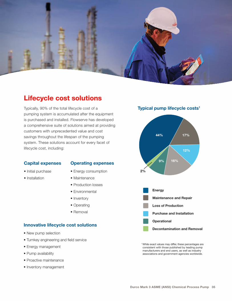
Typically, 90% of the total lifecycle cost of a
pumping system is accumulated after the equipment
is purchased and installed. Flowserve has developed
a comprehensive suite of solutions aimed at providing
customers with unprecedented value and cost
savings throughout the lifespan of the pumping
system. These solutions account for every facet of
lifecycle cost, including:
Capital expenses
• Initial purchase
• Installation
Lifecycle cost solutions
Operating expenses
• Energy consumption
• Maintenance
• Production losses
• Environmental
• Inventory
• Operating
• Removal
Innovative lifecycle cost solutions
• New pump selection
• Turnkey engineering and field service
• Energy management
• Pump availability
• Proactive maintenance
• Inventory management
Energy
Maintenance and Repair
Loss of Production
Purchase and Installation
Operational
Decontamination and Removal
2%
44% 17%
12%
16%9%
1 While exact values may differ, these percentages are consistent with those published by leading pump manufacturers and end users, as well as industry associations and government agencies worldwide.
Typical pump lifecycle costs1
flowserve.com
Flowserve Corporation5215 North O’Connor Blvd.Suite 2300Irving, Texas 75039-5421 USATelephone: +1 937 890 5839
PS-10-13p (E) June 2018
Flowserve Corporation has established industry leadership in the design and manufacture of its products. When properly selected, this Flowserve product is designed to perform its intended function safely during its useful life. However, the purchaser or user of Flowserve products should be aware that Flowserve products might be used in numerous applications under a wide variety of industrial service conditions. Although Flowserve can provide general guidelines, it cannot provide specific data and warnings for all possible applications. The purchaser/user must therefore assume the ultimate responsibility for the proper sizing and selection, installation, operation, and maintenance of Flowserve products. The purchaser/user should read and understand the Installation Instructions included with the product, and train its employees and contractors in the safe use of Flowserve products in connection with the specific application.
While the information and specifications contained in this literature are believed to be accurate, they are supplied for informative purposes only and should not be considered certified or as a guarantee of satisfactory results by reliance thereon. Nothing contained herein is to be construed as a warranty or guarantee, express or implied, regarding any matter with respect to this product. Because Flowserve is continually improving and upgrading its product design, the specifications, dimensions and information contained herein are subject to change without notice. Should any question arise concerning these provisions, the purchaser/user should contact Flowserve Corporation at any one of its worldwide operations or offices.
©2018 Flowserve Corporation. All rights reserved. This document contains registered and unregistered trademarks of Flowserve Corporation. Other company, product, or service names may be trademarks or service marks of their respective companies.