mark charangwa supervisor: a professor m. e. dlodlo
TRANSCRIPT
Univers
ity of
Cap
e Tow
n
i
Evaluating the effectiveness of Cooperative/Coordinated
Multipoint (CoMP) LTE feature in Uplink and Downlink
Transmissions
Mark Charangwa
Supervisor: A Professor M. E. Dlodlo
This minor dissertation is submitted in partial fulfilment of the academic requirements
for the degree of
Master of Engineering (Telecommunications)
in the Faculty of Engineering and The Built Environment
University of Cape Town
2017

The copyright of this thesis vests in the author. No quotation from it or information derived from it is to be published without full acknowledgement of the source. The thesis is to be used for private study or non-commercial research purposes only.
Published by the University of Cape Town (UCT) in terms of the non-exclusive license granted to UCT by the author.
Univers
ity of
Cap
e Tow
n

ii
As the candidate’s supervisor, I have approved this minor dissertation for submission.
Name: Dr. Mqhele E. Dlodlo, Associate Professor
Signed: ______________________
Date: ______2017-10-28__________

iii
Declaration
I declare that this dissertation is my own work. Where collaboration with other people has
taken place, or material generated by other researchers is included, the parties and/or materials are
indicated in the acknowledgements or are explicitly stated with references as appropriate.
This work is being submitted for the Master of Science in Electrical Engineering at the
University of Cape Town. It has not been submitted to any other university for any other degree
or examination.
Mark Charangwa 29 March 2017
Name Date

iv
Dedication
I dedicate this work to everyone who provided technical, moral and financial support.

v
Abstract
Shannon demonstrated that the channel capacity depends of the ratio of the received signal
power to interference plus noise power (SINR). Inter-cell interference caused by neighbouring
base stations (BSs) has been identified as one of the most severe problem towards the deployment
of LTE technology as it can significantly deteriorate the performance of cell-side User Equipment
(UE).
However, because of regulatory and radiation restrictions as well as operational costs,
signal power may only be increased only up to a certain limit to reduce the interference. The other
common radio propagation impairment is multipath. Multipath refers to a scenario where multiple
copies of a signal propagate to a receiver using different paths. The paths can be created due to
signal reflection, scattering and diffraction. As will be discussed later the effects of multipath
contribute little to intercell interference because multipath characteristics such as delay spread are
compensated for using cyclic prefixes.
In this work, we will limit our scope to interference as it has been identified as the main cause of
performance degradation for cell edge users due to the full frequency reuse technique used in LTE.
To mitigate interference 3GPP devised options of increasing the capacity in LTE-Advanced
Release 12 which include the use of spectral aggregation, employing Multiple Input and Multiple
Output (MIMO) Antenna techniques, deploying more base stations and micro and femto cells,
increasing the degree of sectorisation and Coordinated Multipoint (CoMP). We are primarily
interested in evaluating performance improvements introduced when uplink (UL) and downlink
(DL) coordinated/cooperative multipoint (CoMP) is enabled in LTE Advanced Release 12 as a
way of reducing interference among sites. The CoMP option of reducing interference does not
require deployment of new equipment compared to the other options mentioned above hence
network deployment costs are minimal. CoMP in theory is known to reduce interference especially
for cell edge users and therefore improves network fairness. With CoMP, multiple points
coordinate with each other such that transmission of signals to and from other points do not incur
serious interference or the interference can even be exploited as a meaningful signal.
vi
In September 2011 work on specifications for CoMP support was started in 3GPP LTE-
Advanced as one of the core features in LTE-Advanced Release 11 to improve cell edge user
throughput as well as the average network throughput.
We set to do field measurements in the evaluation of the effectiveness of CoMP in LTE.
3GPP LTE Release 12 was used and cell edge users’ performance was the focus. The network
operates in 2330 – 2350 MHz band (Channel 40). From the field measurements, it was
demonstrated that the CoMP (Scenario 2) feature indeed effective in improving service
quality/user experience/fairness for cell edge users. CoMP inherently improves network capacity.
A seven (7) percent throughput was noticed.

vii
Acknowledgements
I would like to sincerely thank my family, Professor M. E. Dlodlo, Syed Baarrij for their
patience, insight and invaluable contribution into my work.
My family had to put up with the time that I invested into this work as well as providing
moral support.
Professor M. E. Dlodlo, my supervisor, scrutinised my work and provided technical
guidance in addition to moral support and encouragement.
Syed Baarrij is the Project Manager for Liquid Telecom Group and the overseer in the
deployment of LTE in Zambia. He provided technical direction and allowed me to use the network
for my research

viii
Table of Contents
Declaration.................................................................................................................................... iii
Abstract .......................................................................................................................................... v
Acknowledgements ..................................................................................................................... vii
List of Figures ................................................................................................................................ x
1 Introduction ............................................................................................................................. 1
1.1 Background ........................................................................................................................................ 1
1.2 Objectives and Goals ......................................................................................................................... 1
1.3 Scope and limitations ......................................................................................................................... 1
1.4 Strategy ............................................................................................................................................... 2
1.5 Summary ............................................................................................................................................. 3
1.6 Project Outline ................................................................................................................................... 3
2 Literature Review .................................................................................................................... 5
2.1 Information Theory ........................................................................................................................... 5
2.1.1 Channel Coding in LTE ..................................................................................................................................... 5
2.2 Orthogonal Frequency Division Multiplexing Overview ............................................................... 9
2.2.1 OFDM Implementation using IFFT/FFT Processing ...................................................................................... 10
2.2.2 Channel Coding with OFDM .......................................................................................................................... 11
2.2.3 OFDM Parameters .......................................................................................................................................... 12
2.2.4 Summary .......................................................................................................................................................... 13
2.3 LTE Design Targets, Basics and Building Blocks ......................................................................... 14
2.3.1 LTE Basics ...................................................................................................................................................... 14
2.3.2 Radio Protocol Structure................................................................................................................................. 16
2.3.3 Scheduler ......................................................................................................................................................... 18
2.3.4 Control Plane Protocols .................................................................................................................................. 18
2.3.5 Physical Transmission Resources ................................................................................................................... 19
2.3.6 Physical Resource Block Structure ................................................................................................................. 24
2.3.7 Downlink Reference Signals ............................................................................................................................ 26
2.3.8 Multi-antenna .................................................................................................................................................. 27
2.3.9 Multiple Antenna Transmission ....................................................................................................................... 28
2.3.10 Spectrum ........................................................................................................................................................ 29
2.3.11 LTE Release 12.............................................................................................................................................. 30
2.3.12 Summary ........................................................................................................................................................ 30
ix
2.4 Cooperative Multipoint (CoMP) ..................................................................................................... 31
2.4.1 CoMP Basics ................................................................................................................................................... 31
2.4.2 Link Adaptation ............................................................................................................................................... 33
2.4.3 Channel State Information .............................................................................................................................. 33
2.4.4 Downlink CoMP .............................................................................................................................................. 34
2.4.5 Uplink CoMP................................................................................................................................................... 35
2.4.6 CoMP Deployment Scenarios and Operation ................................................................................................. 35
2.4.7 Performance .................................................................................................................................................... 37
2.4.8 Summary .......................................................................................................................................................... 38
2.5 Chapter summary ............................................................................................................................ 38
3 Measurement/Experimental Setup ...................................................................................... 39
3.1 DL CoMP .......................................................................................................................................... 39
3.2 UL CoMP .......................................................................................................................................... 40
3.3 Field Trials ........................................................................................................................................ 40
4 Research Output .................................................................................................................... 41
4.1 Analysis and KPIs ............................................................................................................................ 41
4.1.1 RRC/S1 Signalling/ E-RAB Success Rate (%) ................................................................................................. 41
4.1.2 Call drop Rate (%) .......................................................................................................................................... 44
4.1.3 DL Throughput /DL User Edge Throughput (Kbps) ....................................................................................... 45
4.1.4 Intra-freq HO out Success Rate (%) ................................................................................................................ 47
4.2 Summary ........................................................................................................................................... 49
5 Conclusion and Recommendations ...................................................................................... 50
5.1 Conclusion ........................................................................................................................................ 50
5.2 Recommendation .............................................................................................................................. 50
References .................................................................................................................................... 52
x
List of Figures
Figure 1 ............................................................................................................................... 6
Figure 2 ............................................................................................................................... 7
Figure 3 .............................................................................................................................. 7
Figure 4 ............................................................................................................................ 11
Figure 5 ............................................................................................................................ 12
Figure 6 ............................................................................................................................. 16
Figure 7 ............................................................................................................................ 17
Figure 8 ............................................................................................................................ 21
Figure 9 ............................................................................................................................ 22
Figure 10 .......................................................................................................................... 22
Figure 11 .......................................................................................................................... 24
Figure 12 .......................................................................................................................... 37
Figure 13 ........................................................................................................................... 40
Figure 14 .......................................................................................................................... 42
Figure 15 ........................................................................................................................... 43
Figure 16 .......................................................................................................................... 45
Figure 17 .......................................................................................................................... 46
Figure 18 ........................................................................................................................... 48
Figure 19 ........................................................................................................................... 49
1
Chapter 1
1 Introduction
1.1 Background
As more and more applications that try to make our day to day life convenient and improve
business processes are being developed and churned out, so have the requirements for high data
rates (throughput) also increased. Up until 3G and 4G technologies cellular networks employed
the concept of network planning with frequency reuse patterns leading to inefficient scarce
resource utilisation. LTE-Advanced uses the concept of full frequency reuse to address the
inefficiencies associated with network planning [1] leading yet to another problem of intra-cell
and inter-cell interference. However, theoretically CoMP has been shown to be able to reduce
interference and therefore address interference caused by full frequency reuse.
To understand the CoMP scheme there is need to fully appreciate the technologies used in LTE
and the LTE architecture itself. Therefore, in this document we are going to review the theory of
technologies that form the foundation of the LTE technology and these include Information
Theory, Orthogonal Frequency Division Multiplexing, Multiple Antenna Techniques, LTE air
interface as applicable to LTE and finally, our focus, Cooperative MultiPoint (CoMP). Are the
review we will then conduct measurements in a real and live commercial network to ascertain
practically the interference reduction and therefore performance improvements brought by CoMP
1.2 Objectives and Goals
The objective of the dissertation is to practically and quantitatively evaluate the benefits derived
from using or activating the CoMP feature in an LTE network.
The project uses Intra-freq HO out Success Rate (%), DL Throughput /DL User Edge Throughput
(Kbps), Call drop Rate (%) and RRC/S1 Signalling/ E-RAB Success Rate (%) Key Performance
Indicators (KPIs) in quantifying performance improvements brought about by using CoMP.
1.3 Scope and limitations

2
The project scope is limited to using CoMP as a technological feature to reduce interference as it
has been identified as the main cause of performance degradation for cell edge users caused by
full frequency reuse technique used in LTE.
From Equation 1 below we can clearly see that the major limiting factor for a radio system with
frequency reuse is interference (I) since there is not much we can do about the noise (N) hence
motivating the basis for this work.
To mitigate interference 3GPP devised options of increasing the capacity in LTE-Advanced
Release 12 which include the use of spectral aggregation, employing Multiple Input and Multiple
Output (MIMO) Antenna techniques, deploying more base stations and micro and femto cells,
increasing the degree of sectorisation and Coordinated Multipoint (CoMP).
Also, from a practical point of view since this is a live commercial network we had to be cautious
in terms disrupting customers’ services, that is, not to cause significant downtime. We therefore
could not manage all CoMP parameters as to evaluate the maximum performance improvement
we can achieve with this feature.
sSINR
N I
(1)
Where: S = the signal strength,
I = interference from other base stations, and,
N = thermal noise
1.4 Strategy
The LTE network is benchmarked six days before enabling the CoMP features and measurements
(KPIs) will be collected for another six days after CoMP is enabled.
These KPIs are collected before and after enabling the CoMP feature using a commercial
Operations Support Systems (OSS) and well as conducting drive tests to generate traffic.
The KPIs are chosen for reasons below and the detailed explanation of the KPIs is in chapter 4;
3
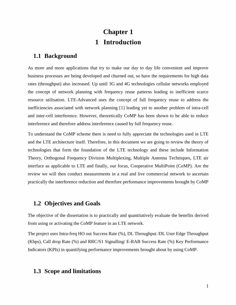
Intra-freq HO out Success Rate (%) – for a handover to be successful the radio channel must be
reliable. Therefore, we can safely infer that a high HO success rate indicated that good channel.
Conversely, a low HO success rate infers that the radio channel between a UE and a eNodeB is
not good. This is especially true in the network being used because fibre backhaul is used and the
MME is lightly loaded since the network is still new.
DL Throughput /DL User Edge Throughput (Kbps) - this KPI provided an indication of the
overall user experience.
Call drop Rate (%) - this retainability KPI occurs when a radio access bearer (E-RAB) is
abnormally released. Again, this points to the channel state between the UE and eNodeB
RRC/S1 Signalling/ E-RAB Success Rate (%) - according to [2] the KPI’s measurement scope
is in a cell or radio network. A high E-RAB success rate directly relates to QoS Class Identifiers
(QCI).
1.5 Summary
In this introductory chapter, the objectives and goals of this investigation were outlined. The
scope, strategy and limitations are also defined.
Since the project is based on measurements it was necessary for Key Performance Indicated (KPIs)
that are relevant in evaluating the effectiveness of enabling the CoMP feature to be stated.
We looked at some of the motives for the need of more bandwidth. In Chapter 2 we review the
Information theory, Orthogonal Frequency Division Multiplexing, LTE as a technology employing
(Information Theory and OFDM) and the CoMP feature.
1.6 Project Outline
This introductory Chapter gave an outline of the Objectives, Goals, Scope and the limitations
encountered in the field experiments carried out. The Chapter also explained the strategy used in
evaluating the LTE improvements brought about by using CoMP, that is, benchmarking and
relevant KPIs measured.

4
Chapter 2 provides literature review of the theories, building blocks and core technologies used in
LTE.
Chapter 3 explains the field measurement setup used in our experiment.
Chapter 4 presents the research output as well as explanations of the relevant KPIs used in
evaluating the effectiveness of the CoMP feature.
Finally, conclusions and recommendations with respect to the field measurements and output, and
recommendations for further work to be carried out in LTE are made in Chapter 5. I am of the
strong opinion that as LTE matures “best practices” documents which can be used as references
by Network Operators should also be produced so that maximum performance is realised in LTE
deployments.

5
Chapter 2
2 Literature Review
2.1 Information Theory
In [3], Shannon provided the basic theoretical tools necessary in determining the maximum rate,
also known as the channel capacity, by which information can be transferred over a given
communication channel reliably or in other words error free. For practical purposes, the tools are
relatively complicated in the general case. However, for the special case of communication link
impaired only by additive white Gaussian noise, for instance a radio link, the channel capacity C
is given by the simple expression (2)[3]
(2)
From (2) we can clearly observe that there are two main parameters that can be varied to achieve
a certain capacity – the signal to noise ratio (S/N) and bandwidth (BW) (Hz). Due to the shortage
or finiteness or scarcity of radio spectrum one can increase the bandwidth only to a certain extent.
Also, the equipment which operate with high bandwidth are also relatively expensive because the
filter design is generally complicated. As indicated above, techniques such as Multiple Input and
Multiple Output (MIMO) Antenna techniques, deploying more base stations and micro and femto
cells, increasing the degree of sectorisation and Coordinated Multipoint (CoMP). CoMP features
are proposed and are continuously being researched on and implemented to improve the SINR.
2.1.1 Channel Coding in LTE
With reference to LTE Channel coding consists mainly of the Cyclic Redundancy Check and
Turbo Coding schemes. Below we will take a review of both schemes.
2.1.1.1 Cyclic Redundancy Check
In digital communication systems and storage devices the error-detection code/scheme
predominantly employed is the cyclic redundancy check (CRC) to detect data errors due to a
number of phenomenon. Blocks of data entering these systems have a short value calculated and
attached. The calculation is based on the remainder of a polynomial division of the block of data

6
contents. Upon retrieval of the data the exact same calculation is repeated and the newly calculated
value is matched to the one calculated when the blocks of data entered the system. An error would
have occurred when these CRC values do not match warranting an error correction action can be
taken on the corrupted data.
gCRC24A and gCRC24B schemes are two cyclic redundancy check schemes used for a Physical
Downlink Shared Channel (PDSCH) used in LTE. These schemes use a 24 parity bits length
though they use different cyclic generator polynomials. The ‘gCRC24A’ focuses on a transport
block, while the ‘gCRC24B’ focuses on the code block, which is the segmentation of a transport
block when the size of a transport block is larger than the upper limit (6144 bits). See figure 1.
Figure 1
2.1.1.2 Turbo Coding
Physical Downlink Shared Channel (PDSCH) channel coding scheme uses Turbo Coding. Turbo
coding is considered a robust channel coding. Scheme because when using an AWGN channel,
the performance of Turbo codes can approach to the theoretical Shannon capacity limits. An
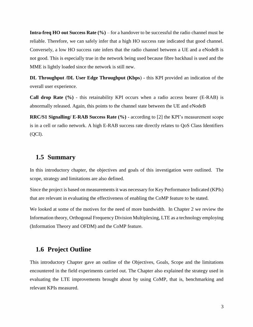
example of a typical error performance of an un-coded versus a turbo coded forward error
correction coded system is shown in figure 2.
7
Figure 2
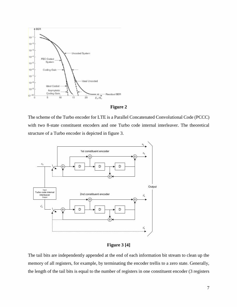
The scheme of the Turbo encoder for LTE is a Parallel Concatenated Convolutional Code (PCCC)
with two 8-state constituent encoders and one Turbo code internal interleaver. The theoretical
structure of a Turbo encoder is depicted in figure 3.
DD D
DD D
Input
Turbo code internal
interleaverOutput
Output
1st constituent encoder
2nd constituent encoder
kc
kc
kx
kx
kz
kz
Figure 3 [4]
The tail bits are independently appended at the end of each information bit stream to clean up the
memory of all registers, for example, by terminating the encoder trellis to a zero state. Generally,
the length of the tail bits is equal to the number of registers in one constituent encoder (3 registers

8
are used in one constituent encoder in LTE). The sequence of tail bits is rearranged and 4 tail bits
are attached after each information bit stream. Hence, the length of each bit stream becomes 4+K.
With the three information bit streams, the original Turbo coding rate is 1/3. However, after
padding tail bits, the coding rate will decrease a bit. Furthermore, by puncturing or repeating the
output of Turbo coding, it can accomplish an alterable channel coding rate under different
scenarios, according to the channel conditions. Such process is implemented by the circular buffer
at the rate-matching block.
9
2.2 Orthogonal Frequency Division Multiplexing Overview
Wireless channels have memory, due to the multipath phenomenon, making them dispersive which
in turn causes inter-symbol interference (ISI). Typical outdoor environments like GSM experience
maximum delay spreads in the order of 15microseconds [3]. The Inter-symbol interference is more
pronounced when the transmitted symbol duration is short compared to the delay spread. In other
words, transmission error statistics can be made negligible if the transmitted symbol duration is
made significantly longer relative to the delay spread. One method of combating the inter-symbol
interference is to employ equalisation in receivers. An alternative solution is the use of OFDM.
The use of orthogonal subcarriers allows more subcarriers per bandwidth resulting in an increase
in spectral efficiency.
OFDM employs multiple overlapping carriers in the frequency domain. OFDM is different from
a pure multicarrier system in that OFDM uses many narrowband subcarriers whereas a multicarrier
system consists of a smaller number of subcarriers with wide bandwidth compared to OFDM.
Rather than transmit a high-rate stream of data with a single subcarrier, OFDM makes use of many
closely spaced orthogonal subcarriers that are transmitted in parallel. Orthogonal Frequency-
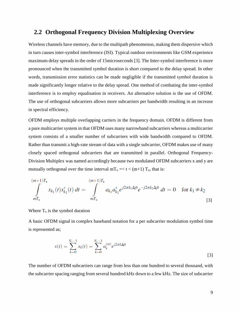
Division Multiplex was named accordingly because two modulated OFDM subcarriers x and y are
mutually orthogonal over the time interval mTu =< t < (m+1) Tu, that is:
[3]
Where Tu is the symbol duration
A basic OFDM signal in complex baseband notation for a per subcarrier modulation symbol time
is represented as;
[3]
The number of OFDM subcarriers can range from less than one hundred to several thousand, with
the subcarrier spacing ranging from several hundred kHz down to a few kHz. The size of subcarrier

10
spacing to use depends on the environment the network is to operate in. The environment can be
described by such aspects as the maximum expected radio-channel frequency selectivity
(maximum expected time dispersion) and the maximum expected rate of channel variations
(maximum expected Doppler spread).
2.2.1 OFDM Implementation using IFFT/FFT Processing
Digital signal processing transforms like the Fast Fourier Transform (FFT) and Inverse Fast
Fourier Transform (IFFT) are very crucial from an orthogonal frequency division multiplexing
point of view because they can be perceived as mapping digitally modulated input data (data
symbols) onto the orthogonal subcarriers. When an orthogonal frequency division system is
implemented digitally input data bits are grouped and mapped to source data symbols that are a
complex number representing the modulation constellation point, for example the binary phase
shift keying or quadrature amplitude modulation symbols that would be present in a single
subcarrier system.
The transmitter treats the complex source symbols as being in the frequency-domain and these
symbols in turn form the inputs to an IFFT block to transform the data into the time-domain. N
source symbols are taken by the IFFT at a time with each of these N input symbols having a symbol
period of T seconds. Here N is the number of subcarriers in the system. The output of the IFFT is
N orthogonal sinusoids and these orthogonal sinusoids each have a different frequency and the
lowest frequency being a DC.
As stated above the input symbols are complex values representing the mapped constellation point
and therefore specify the phase and amplitude for that subcarrier sinusoid. The output of the IFFT
process is a summation of all N sinusoids. Therefore, the IFFT block is a simple method of
modulating data onto the N orthogonal subcarriers. Thus, a single OFDM symbol is made up of a
block of N output samples from the IFFT.
After some additional processing, the time-domain signal that results from the IFFT is transmitted
across the radio channel. At the receiver, an FFT block is used to process the received signal and
bring it into the frequency domain which is used to recover the original data bits.

11
2.2.2 Channel Coding with OFDM
Every wireless channel is subject to frequency selectivity meaning that the channel quality varies
in the frequency domain. WCDMA uses a single wideband channel, hence the modulated symbol
is transmitted over the entire signal bandwidth. For these wideband technologies or
implementations with a highly frequency selective channel, the symbol is transmitted in both good
and bad frequency bands as depicted in figure 4 (a) below.
However, since OFDM uses narrow subcarriers meaning that the OFDM modulation symbol is
transmitted over a relatively narrow bandwidth. Therefore, in a frequency selective channel an
entire modulation symbol can be confined to a frequency band with poor quality. It is against this
that the basic error-rate performance of OFDM transmission over a frequency selective channel is
relatively poor and especially much worse than the basic error rate in the case of a single wideband
carrier. See figure 4 (b).
The poor error rate performance of OFDM warranted the need to implement a form of channel
coding. Channel coding means that the bit of information to be transmitted is spread over several
code bits.
Figure 4 [5]

12
Figure 5 [5]
Frequency interleaving on the other hand means that the code bits are distributed bits in the
frequency domain. As illustrated in figure 5 above the code bits will experience diversity when
transmitted over frequency selective channel. It is quite evident that channel coding in combination
with frequency interleaving is an indispensable tool for OFDM transmission to be able to improve
performance in a frequency-selective channel at the same time benefiting from the frequency
diversity [14].
2.2.3 OFDM Parameters
For OFDM to be used in mobile networks the below parameters need to be decided upon for good
performance achievement.
• The subcarrier spacing, f .
• The number of subcarriers Nc, which, together with the subcarrier spacing,
determines the overall transmission bandwidth of the OFDM signal.
• The cyclic-prefix length TCP. Together with the subcarrier spacing 1/ uf T the
cyclic-prefix length determines the overall OFDM symbol time CP uT T T or, equivalently, the
OFDM symbol rate [14].

13
2.2.4 Summary
This section explored the benefits and implementation strategies for Orthogonal Frequency
Division Multiplexing. The section also expanded on the concept of coding as introduced in section
2.1, in particular, and as it is used in LTE. It also introduced some of the parameters to be decided
upon to achieve high performance. Section 2.3 is used to introduce the Long-Term Evolution
(LTE) technology, its goals, design and architecture.

14
2.3 LTE Design Targets, Basics and Building Blocks
3GPP started working on LTE in 2004 by defining its performance and capability targets [1]. The
objective was to design a new radio protocol suited for packet switched data only. Among the
targets included peak data rates, spectral efficiency, control and data plane latency as well as
user/system throughput. Release 8 was the first LTE specifications and completed in 2008. Release
12 which forms the basis for this document was largely completed in March 2015.
Design targets for LTE Release 12 are documented in 3GPP TR 25.913. The target capability when
operating in a 20 MHz spectrum allocation is a peak data rate of 100 Mbit/s in the downlink and
50 Mbit/s in the uplink.
With LTE release 10 3GPP did not specify exact targets for peak data rates. However, peak spectral
efficiency targets of like 6.75 bit/s/MHz and for uplink 15 bit/s/Hz for downlink were specified
relative to the channel. The above peak spectral efficiency targets assumed 20MHz channel
bandwidth, 4x4 MIMO in the uplink and 8x8 MIMO in the downlink.
2.3.1 LTE Basics
In UMTS the base station is named NodeB and in LTE it is renamed an Evolved Node B. The
renaming emphasises the added functionalities of these base stations. For instance, the eNodeBs
carry the handover functionality of the radio connection to a neighbouring base station which was
carried out by the RNC in UMTS [6].
For the purposes of this work we will mainly look at the radio aspect of LTE. LTE uses OFDM as
the downlink transmission scheme and SC-OFDM in the uplink to combat peak average power
radio (PAPR) effects inherent with OFDM which affect the design and cost of power amplifiers in
the base station receive path (uplink). The OFDMA symbol is a combination of symbols from
other subcarriers hence in-phase subcarrier voltages can add within the symbol resulting in high
instantaneous power that is much higher than the average power. The transmitter power amplifier
efficiency is reduced due to this dramatic power variation. For this reason, SC-FDMA is used in

15
the uplink to save on terminal battery. Another characteristic of LTE is its spectrum flexibility in
that
LTE transmission scheme employs the use of shared-channel transmission with users dynamically
sharing the overall time–frequency resource dynamically. The shared channel transmission scheme
is very appropriate since LTE uses packet data communication. The task of sharing the time-
frequency resources is done what is called, and appropriately named, a scheduler. Since the
scheduler varies resource assignment based on data rate requirements by users. This makes the
scheduler as another dimension in the determination of the overall system capacity. Put differently
the scheduler is seen to perform the rate adaption function. The scheduler also considers the
channel conditions in its scheduling of resources and this is known as channel dependant
scheduling. Channel-dependent scheduling relies on channel-quality variations between users to
obtain a gain in system capacity.
In LTE, scheduling decisions can be taken as often as once every 1 ms and with a granularity of
180Hz in the frequency domain.
The RAN is responsible for all radio-related functionality of the overall network including, for
example, scheduling, radio-resource handling, retransmission protocols, coding and various multi-
antenna schemes.
The LTE radio-access network uses a flat architecture with a single type of node called the
eNodeB. The eNodeB is a logical node responsible for all radio-related functions in one or several
cells. One common implementation of an eNodeB is a three-sector site, where a base station is
handling transmissions in three cells. The X2 interface that connects the eNodeBs is used for
supporting active mobility and multi-cell radio resource management (RRM) functions e.g. ICIC
and CoMP.

16
2.3.2 Radio Protocol Structure
Figure 6 [7]
Figure 7 below shows the layered structure of LTE radio protocol architecture. The radio protocol
layers include the Packet data convergence protocol (PDCP), radio link control (RLC), media
access control (MAC) and the physical (PHY) layers. Header compression and ciphering at the
transmitter and header decompression and deciphering at the receiver functions are carried out by
the PDCP.
Radio-Link Control (RLC) takes care of the segmentation & concatenation, retransmissions,
detection of duplications and naturally the in-sequence delivery to higher layers. As can be seen
in figure 7, the radio link control renders services to the PDCP. Multiplexing of the logical channels
is the responsibility of the medium-access control (MAC) as well as hybrid-ARQ retransmissions,
and uplink and downlink scheduling. The scheduling functionality is in the eNodeB for both uplink
and downlink.

17
Figure 7 [7]
Coding or decoding, modulation or demodulation, multi-antenna mapping together with other
physical layer functions are handled by the Physical Layer (PHY). The physical layer offers
services to the MAC layer in the form of transport channels. Depending on how and the
characteristics of the information to be transmitted on the radio interface define a transport channel.
Data on a transport channel is organized into transport blocks and at one transport block is
transmitted in what is termed a Transmission Time Interval (TTI). The transport block transmitted
on the radio interface is of dynamic size. One transport block is transmitted over the radio interface
to and from a terminal when spatial multiplexing is not used. Were spatial multiplexing (MIMO)
is used, a maximum of two transport blocks can be transmitted per TTI. Associated with each
transport block is a Transport Format (TF), specifying how the transport block is to be transmitted
over the radio interface. The transport format includes information about the transport-block size,

18
the modulation-and-coding scheme, and the antenna mapping. By varying the transport format, the
MAC layer can thus realize different data rates. Rate control is also known as transport-format
selection.
2.3.3 Scheduler
With LTE data uses what is called a shared channel transmission, basically meaning that the time-
frequency resources are dynamically allocated to users. This function of dynamically allocating
resources is carried out by the scheduler which resides in the MAC layer. The scheduler has the
autonomy to control assignment of uplink and downlink resources in terms of resource-block pairs.
A resource block pair is defined as corresponding to a time-frequency unit of 1ms and 180 kHz.
For downlink transmissions, the eNodeB had to naturally perform or coordinate the TF selection.
As alluded to above this is the selection of transport block size, modulation scheme, and antenna
mapping. Downlink channel dependent scheduling is performed in conjunction with the channel
state information as reported by user equipment.
In the uplink channel static information necessary for channel dependant scheduling can be based
on the sounding reference signal transmitted from the UE the eNodeB requires to estimate the
channel state.
Hybrid ARQ, HARQ in short, provides a mechanism of robustness against transmission errors in
LTE. This is accomplished by having a receiver send an acknowledgement bit indicating success
or fail in decoding a received. In the case of a decoding failure the transport block is retransmitted.
HARQ is supported for Downlink Shared Channel (DLSCH) and the Uplink Shared Channel
(ULSCH) traffic. Broadcast traffic types do not have the HARQ functionality since the traffic is
intended multiple terminals.
2.3.4 Control Plane Protocols
Control messages can originate from the MME or RRC in the eNodeB and these messages are
connection setup, mobility and security. The RRC controls the radio access network related
procedures which include;
19
- Measurement configuration and reporting.
- Determination of user equipment capabilities
- Management of connections and this includes setting up bearers and mobility
- Broadcast of system information necessary for terminals to be able to communicate with
cell.
RRC messages are transmitted to terminals using Signalling Radio Bearers (SRB) which are in
turn mapped to the Common Control Channel (CCCH) during connection setup and to the
Dedicated Control Channel (DCCH) thereafter.
A Bearer can be visualised as a pipe that connects two or more points in a communication system,
through which the data flows.
More technically a bearer is a channel that carries user data, that is, a logical connection between
different nodes that guarantees the quality of service attributes for packets flowing on the bearer.
For quality of service guarantees it therefore implies that each bearer channel must be associated
with QoS parameters. Examples of such parameters include delay, jitter and packet loss.
2.3.5 Physical Transmission Resources
In LTE both downlink and uplink transmissions use radio frames that are 10ms in duration. Two
types of frames are defined or supported in the Evolved UTRAN. Type 1 is defined for Frequency
Division duplexing and Type 2 for time division duplexing. A system frame number (SFN), which
is a group of 10 bits, is used to number the frames. From the 10 bits, the integer values range from
0 to 1023.
Due to wireless characteristics like multipath which result in the wireless channel being dispersive
two cyclic prefixes have been defined in LTE. The normal (short) cyclic prefixes are defines more
for urban environments where there is a dense deployment of small cells. On the other hand,
extended (long) cyclic prefixes is meant for environments with large cell deployments, like rural
areas, were the delay spreads are long. Also, the extended CP is suitable for transmissions like in
MBSFN were many cells are involved in the transmission of a signal to terminals. In the case the
extended CP mitigates against timing differences between cell transmissions.

20
The figure 8 and figure 9 below shows the structure of the both frame type 1 and type 2.
2.3.5.1 Frame Type 1
Type 1 frame structure is used for both full-duplex frequency division duplexing as well as hall
duplex frequency division duplexing schemes. In frame structure type 1, as illustrated in Figure 8,
10 equally subframes make one 10ms radio frame. Further each subframe is composed two
consecutive and equally sized, a slot being 0.5ms in duration. It is in these 0.5ms slots that the
OFDM symbols are contained. The number of OFDM symbols contained in each slot can be either
be seven or six depending on whether the normal cyclic prefix or the extended cyclic prefix is
used. As figure 8 below depicts, the useful symbol time is Tu 52048Ts 566:7 μs. For a normal
cyclic prefix, the first symbol has a cyclic prefix lengths of TCP 5160Ts 55:2 μs [8].
The remaining six OFDM symbols have a cyclic prefix of length TCP 5144Ts 54:7 μs so that the
different cyclic prefix lengths of the first symbol are to make the overall slot length in terms of
time units divisible by 15,360. For the extended mode, the cyclic prefix is TCP 5512Ts 516:67 μs.
The cyclic prefix duration is designed to be longer compared to the delay spread of a few
microseconds normally experienced in real world environments. Urban environments usually have
small cell sizes, for capacity reasons, and therefore the normal cyclic prefix is utilised for such
environments. On the other hand, in very large cells the extended cyclic prefix is used.
A 1ms transmission time interval (TTI) is used for both E-UTRA downlink and uplink. The TTI
is defined as the duration of the transmission of the physical layer encoded packets over the radio
air-interface [8].
The number of sub-carriers used in the frequency domain varies from 128 to 2048, depending on
the channel bandwidth. For instance, 512 and 1024 are used for 5 and 10 MHz bandwidths
respectively. As discussed in section 3.7 a sub-carrier spacing of 15 kHz is used in LTE. [8].

21
Figure 8 [4]
2.3.5.2 Frame Type 2
Frame structure type 2 are utilised in a time division duplexing duplex scheme in which the
downlink and uplink transmissions are time-multiplexed over the extent of a radio frame, see
Figure 9. Like Type 1 the radio frame is 10ms in length and is composed of two half-frames, with
each half-frame consisting of five subframes of length 1 ms.
Table 1 below shows the 3GPP defined downlink/uplink ratios, that is, the ratio of downlink and
uplink subframes in a frame and shown in Figure 9. In each radio subframe, DL represents the
subframe meant for downlink transmissions, UL represents the subframe meant for uplink
transmissions, and S defines a special subframe consisting of three fields - the downlink pilot time
slot (DwPTS), GP, and uplink pilot time slot (UpPTS). The length of DwPTS and UpPTS are
shown in Table 1 and the total length of DwPTS, GP, and UpPTS is always 1 ms.
In E-UTRA time division duplex (TDD) the supported downlink/uplink ratios are 5 and 10 ms
downlink/uplink switching-point periodicity.

22
Figure 9 [4]
Table 1 [4]
Figure 10 [4]

23
Table 2 [4]

24
A resource element is one subcarrier by one OFDM symbol duration and is the smallest physical
resource in LTE. The minimum scheduling unit is 1ms therefore two resource blocks. The two
resource blocks must be time consecutive and this is referred to as resource block pair. A carrier
can have a minimum of 6 resource blocks and a maximum of 110.
A frame is 10ms and a subframe is 1ms. In the downlink, each subframe has two regions – one for
control (control region) and the data region. The control region is used for L1/L2 signalling.
2.3.6 Physical Resource Block Structure
One sub-carrier over one OFDM symbol is the minimum time-frequency resource known as a
resource element in LTE. In addition, a group of consecutive 12 subcarriers in frequency over one
slot in time is called a Physical resource block (PRB). In LTE, each subcarrier is 15kHz. In turn,
the transmission units are allocated in terms of number of PRB units.
Downlink physical channels defined in LTE are the physical broadcast channel (PBCH), physical
control format indicator (PCFICH)
Figure 11 [4]

25
Physical broadcast channel (PBCH)
The master information block (MIB) part of the system information is transported using this
channel. The PBCH channel is mapped to six resource blocks and the resource blocks are centred
on the DC sub-carrier in subframe 0.
Physical control format indicator channel (PCFICH)
PCFICH is associated to the first orthogonal frequency division multiplexing in each downlink
and has the size of the PDCCH. Its contents are the information on the number of orthogonal
frequency division multiplexing symbols used for the downlink control region. The exact location
of PCFICH is determined by the cell identity and system bandwidth.
Physical hybrid-ARQ indicator channel (PHICH)
The contents of this channel are the HARQ feedback regarding the uplink data transmissions.
Physical downlink control channel (PDCCH)
As the name appropriately implies the channels communicates to the user equipment about
resource allocation, transport format, uplink grants and HARQ feedback. As indicated above the
exact number of the orthogonal frequency division multiplexing for PDCCH is obtained in
PCFICH. Multiple PDCCHs may be monitored by a UE. It also carries uplink power control
commands.
Physical downlink shared channel (PDSCH)
The PDSCH channel carries the downlink data transmission for different users in addition to upper
layer signalling information.
Physical multicast channel (PMCH)
It is used to broadcast MBMS services.
Figure 12 below depicts the location of the downlink physical channels and signals in time and
frequency within a type 1 frame structure.

26
2.3.7 Downlink Reference Signals
In LTE, the downlink reference signals types are the cell specific reference signals (CRS),
demodulation reference signals (DM-RS), channel state information reference signals (CSI-RS)
and positioning reference signals.
CRS are intended to be used by terminals for channel estimation for coherent demodulation of all
downlink physical channels except PMCH, PDSCH in case of transmission modes 7 to 10, and the

27
EPDCCH control channel introduced in LTE release 11 5 CRS are also assumed to be used to
acquire channel-state information (CSI) by terminals configured in transmission modes 1 to 8.
Finally, terminal measurements on cell-specific reference signals are assumed to be used as the
basis for cell-selection and handover decisions.
DM-RS are used for channel estimation whereas CSI-RS are used for acquisition of channel state
information.
CSI-RS have a significantly lower time/frequency density, thus implying less overhead, and more
flexibility compared to the cell-specific reference signals.
MBSFN reference signals are intended to be used by terminals for channel estimation for coherent
demodulation in case of MCH transmission using MBSFN.
Introduced in release 10 CSI-RS are used for terminals to acquire channel state information. The
CSI is used for resource scheduling, link adaption and transmission settings. CSI is used for
terminals configured for transmission modes 9 and 10. Transmission modes 7 & 8 do not support
CSI because they were introduced in release 7 & 8 whilst CSI is introduced in transmission modes
9 & 10. CRS can also be used to acquire CSI but CSI-RS supports up to eight layers special
multiplexing.
In the time domain, CSI-RS can be configured for transmission with different periodicity, ranging
from a period of 5 ms (twice every frame) to 80 ms (every eighth frame).
2.3.8 Multi-antenna
Transmission mode 1 corresponds to single-antenna transmission while the remaining
transmission modes correspond to different multi-antenna transmission schemes, including
transmit diversity, beam-forming, and spatial multiplexing
Transmission mode 10 was introduced in LTE release 11 to support different means of dynamic
multi-point coordination and transmission.
From a terminal point-of-view, the downlink transmission in case of transmission mode 10 is
identical to that of transmission mode 9 in that the terminal will see an up to eight-layers of PDSCH
transmission and rely on DM-RS for channel estimation. One important difference between
transmission mode 9 and transmission mode 10 lies in the acquisition and feedback of channel-

28
state information (CSI) where transmission mode 10 allows for more elaborate multi-point
measurements and feedback based on CSI processes. Transmission modes are only relevant for
DL-SCH transmission.
In practice, terminals configured for transmission modes 1 to 8 can be assumed to rely on CRS to
acquire CSI while, for transmission modes 9 and 10, CSI-RS should be used.
As codebook-based precoding relies on the cell specific reference signals for channel estimation,
and there are at most four cell-specific reference signals in a cell, codebook-based precoding
allows for a maximum of four antenna ports and, consequently, a maximum of four layers.
2.3.9 Multiple Antenna Transmission
Multiple antenna transmission is key to reaching the performance targets of LTE. The minimum
number of receive/transmit antennas in LTE is specified as two. Multiple antennas can be used to
offer receive diversity where the antennas collect additional energy and suppress fading. Multiple
transmit antennas at the base station can be used to transmit diversity and beamforming.
Beamforming improves SINR, hence the overall system capacity and coverage.
Single user MIMO (spatial multiplexing) can be used to improve overall system capacity in that
multiple streams of data can be transmitted using parallel independent channels simultaneously.
With Multiple User MIMO (MU-MIMO) multiple terminals can transmit on the same frequency-
time resources, of course using interference suppression receiver processing, thereby improving
the cell capacity.
These multiple antenna techniques are used in different scenarios, at cell edge or in a loaded cell
the SINR may be low such that using spatial diversity provides limited benefits but one may opt
to use beamforming instead to improve the SINR. On the hand in the high SINR regime improving
the SINR has also limited benefits as the system will now be bandwidth limited rather than SINR
limited. In this case it makes sense to take advantage of the good channel conditions and employ
spatial diversity.

29
2.3.10 Spectrum
LTE can be deployed in both paired (frequency division duplexing) and unpaired (time division
duplexing) spectrum. With TDD downlink and uplink transmissions happen in different non-
overlapping time slots whereas with FDD the uplink and downlink transmissions happen
simultaneously with the use of sufficiently separated frequencies. Prior to LTE this spectrum
flexibility was used the difference being before LTE this was achieved by means of different radio
technologies thereby introducing complexities in the development of dual mode terminals
supporting both FDD and TDD. On the other hand, LTE supports both TDD and FDD in a single
radio technology.
Different regulators in different regions or territories issue varying bandwidth and as well different
frequencies, LTE supports operation in a wide range of spectrum allocations.
In the evolution of LTE, Release 9 introduced additional capabilities which include enhance
beamforming, support for multicast transmission and support for network wide positioning
services. In multi-cell transmission, the same information is transmitted from multiple cells and
by exploiting this at the terminal, using signal power from multiple cell sites at detection, a
substantial improvement in coverage can be realised. By transmitting not only identical signals
from multiple cell sites (with identical coding and modulation), but also synchronizing the
transmission timing between the cells, the signal at the terminal will appear exactly as a signal
transmitted from a single cell site and subject to multi-path propagation. Due to the OFDM
robustness to multi-path propagation, such multi-cell transmission, in 3GPP also referred to as
Multicast/Broadcast Single-Frequency Network (MBSFN) transmission, will then not only
improve the received signal strength, but also eliminate the inter-cell interference. The use of
MBSFN places string requirements for synchronisation and time alignment of the different signal
transmitted from the different cells.
By measuring on special reference signals transmitted regularly from different cell sites, the
location of the terminal can be determined.
LTE release 10 was completed in late 2010 and implied enhanced LTE spectrum flexibility
through carrier aggregation, further extended multi-antenna transmission, introduced support for

30
relaying, and provided improvements around inter-cell interference coordination in heterogeneous
network deployments.
With carrier aggregation (CA), where multiple component carriers are aggregated and jointly used
for transmission to/from a single terminal. CA supports up to five component carriers, possibly
each of different bandwidths, can be aggregated, allowing for transmission bandwidths up to 100
MHz. The component carriers do not have to be contiguous.
2.3.11 LTE Release 12
The primary goal of Rel-12 is to provide mobile operators with new options for increasing
capacity, extending battery life, reducing energy consumption at the network level, maximizing
cost efficiency, supporting diverse applications and traffic types, enhancing backhaul and
providing customers with a richer, faster and more reliable experience [9].
Rel-12 features two Channel State Information (CSI) enhancements: 4Tx (Transmit) Precoding
Matrix Index (PMI) feedback codebook enhancement and aperiodic feedback Physical Uplink
Shared channel (PUSCH) mode 3-2. The CSI enhancements enable the Evolved NodeB (eNB or
eNodeB) to complete delivery of data packets earlier than with legacy CSI feedback, thus
improving spectral efficiency.
2.3.12 Summary
Having explored and now appreciating the targets, design goals and architecture of LTE in this
chapter, we are now equipped to introduce one of the features used in LTE for ensuring consistent
and fair service delivery to all users of the network especially cell edge users. Chapter 4 explores
the cooperative/coordinated multipoint (CoMP) feature and how it ensures consistent user
performance and network fairness.

31
2.4 Cooperative Multipoint (CoMP)
Even more important, in a mobile broadband system dominated by highly dynamic packet-data
traffic there is frequently no data available for transmission at a given transmission point. Having
statically assigned a part of the overall available spectrum to that transmission point with no
possibility to use the corresponding frequency resources to provide higher instantaneous
transmission capacity at neighbouring transmission points would imply an inefficient use of the
available spectrum. Rather, to maximize system efficiency, as well as to enable as high as possible
end-user data rates, a mobile broadband system should be deployed such that, fundamentally, all
frequency resources are available for use at each transmission point.
In the case of scheduling located at a higher-level node above the eNodeB, coordination between
cells of different eNodeB would, at least conceptually, be straightforward as it could be carried out
at the higher-level node. However, in the LTE radio-network architecture there is no higher-level
node defined, and scheduling is assumed to be carried out at the eNodeB.
Thus, the best that can be done from an LTE specification point-of-view is to introduce messages
that convey information about the local scheduling strategy/status between neighbouring
eNodeBs. An eNodeB can then use the information provided by neighbouring eNodeBs as input
to its own scheduling process. It is important to understand though that the LTE specifications do
not specify how an eNodeB should react to this information. Rather, this is up to scheduler
implementation.
The main difference between CoMP and ICIC is that CoMP focused on radio-interface features
and terminal functionality to assist different coordination means.
Release 11 CoMP was limited by the assumption that low latency backhaul was used for
coordination thereby limiting CoMP features to either sectors of the same site or network points
connected by direct low-latency links.
2.4.1 CoMP Basics
The term CoMP refers to a few different classes of schemes, as indicated above, however all the
schemes consider, in one way or the other, intra- and/or inter-site interference to improved fairness
and user data rates.
32
This technique (CoMP) may sometimes be referred to Network MIMO because of its utilisation
of multiple antennas of base stations from different geographically separated sites [10], [11].
Traditionally each UE communicates with the serving cell, however with CoMP the UE
communicates with many cells having differently located points forming the CoMP cooperating
set (MIMO network) [7]. Not only does CoMP utilise radio resources in the time/frequency
domain, it also takes advantage of spatial domain to increase spectral efficiency in terms of the
number of bits/second/hertz. Beamforming makes it possible to use the spatial domain to increase
the spectral efficiency [13].
CoMP schemes/types include Coordinated Scheduling/Beam-Forming (CS/CB) and Joint
Processing (JP) in the downlink and joint reception & coordinated scheduling in the uplink. Most
of these schemes can be categorised according to the extent of information exchange (traffic load)
or coordination among cells and/or base station with UEs.
Cooperative/coordinated multipoint (CoMP) schemes dictate that base stations share user
equipment data scheduling information among themselves. The information sharing in turn results
in increased signalling overhead as well as complexity of the LTE network backhaul deployment.
This backhaul interface in referred to as the X2 interface in LTE.
In downlink CoMP, user equipment measures and reports the channel state information (CSI)
based on the experienced signal to noise and interference ratios of base stations within its vicinity.
The measured CSI report is sent to the base stations in uplink transmission.
In LTE MIMO networks, the linear precoding [17-18] technique is employed as a scheme to
enhance downlink performance in addition to decreasing the signalling overhead between the cells.
3GPP therefore defined a set of predefined precoding matrices to inform the possible channel states
at both the transmitter and the receiver in the CoMP specifications. The Precoding Matrix Index
(PMI), which is defined as the index to the preferred matrix within in a codebook matrix, is
reported by UE together with Channel Quality Indicator (CQI) and MIMO Rank Indicator (RI)
[15].
Rank Indication is one of the important input to eNB, in selection of the transmission layer in
downlink data transmission. Even when the system is configured in transmission mode 3 (or open
loop spatial multiplexing) for a particular UE and if the same UE report the Rank Indication value

33
1 to eNB, eNB will start sending the data in Tx diversity mode to UE. If UE report Rank Indication
2, eNB will start sending the downlink data in MIMO mode (Transmission Mode 3).
We need the RI concept in LTE because when a UE experiences a bad SNR and it would be
difficult (error prone) to decode transmitted downlink data and it sends a warning to eNB by stating
Rank Indication value as 1. When a good SNR is experienced the UE sends this information to
eNB by indicating rank a value as 2. A UE determines the CQI and PMI parameters based on pilot
measurements. The UEs then sends the CQI and PMI to their serving base stations.
The rank indicator (RI) indicates what is called the MIMO ranking, that is, the number of data
streams to be transmitted in parallel for the next transmission over the MIMO channel [16]. These
parameters are transmitted in a quantized manner to BS to reduce signalling overhead. By
coordinating and combining signals from multiple antennas, CoMP makes it possible for UEs to
enjoy consistent performance and quality when they access and share videos, photos and other
high bandwidth services whether they are close to the centre of an LTE-A cell or at its outer edge.
2.4.2 Link Adaptation
Coordinated link adaptation is about using information about transmission decisions of
neighbouring transmission points in the link-adaptation process, that is, in the decision with what
data rate to transmit on a given resource. This is a multistep process in the scheduling and link
adaptation at transmission points and is carried out at the network level.
2.4.3 Channel State Information
UEs are instructed by Base stations on how and which cells’ CSI to measure using CSI Reference
signal (CSI-RS) configuration messages. The UEs in turn measure the CSI and report to their
servicing cells.
The channel state information includes Pre-coding Matrix Indicator (PMI), Channel Quality
Indicator (CQI) and Rank Indicator (RI).
In LTE CQI is a value, ranging from 0 to 15, stating the highest modulation and coding rate (MCR)
supported by a UE supporting a Block Error Rate less than 10%. The better the channel the higher
the MCR used. As much as CQI heavily depends on MCR, it also relates to the signal to
34
interference and noise ratio (SINR) of the wireless channel because Adaptive Coding and
Modulation (ACM) used in LTE to ensure that the block error rate (BLER) is less than 10% has a
direct relation with SINR.
The RI indicates the number of data streams (called layers in 3GPP terms) transmitted to a UE
simultaneously. It therefore implies whether transmit diversity (RI=1) or spatial multiplexing
(RI>1) for an n x m MIMO where n, m > 1.
PMI show how individual data streams (layers) are mapped to transmit antennas in the downlink.
In LTE, a PMI code book is pre-configured at Base stations and UEs to reduce feedback overhead,
hence a UE only sends a PMI index to the base station.
2.4.4 Downlink CoMP
This entails the dynamic cooperation/coordination among multiple geographically separated
transmission points where a point is defined as a set of geographically co-located transmit antennas
In the downlink CoMP can be mainly classified into Coordinated Scheduling/Coordinated
Beamforming (CS/CB) and Joint Processing (JP) schemes.
CS reduces inter or intra- cell interference by allocation difference resource blocks to cell edge
UEs. CS is different from ICIC in that it requires more signal processing and has shorter
operational period (tens to hundreds of ms in ICIC and as short as one ms in CoMP). With ICIC
cells share interference information of each cell whereas in CoMP they share CSI of each user. CS
is usually used in conjunction with CB hence the abbreviation CS/CB scheme.
JP in an umbrella term for Joint transmission (JT) and Dynamic Point Selection (DPS). With JT
multiple cells transmit the same data to a UE using the same radio (time and frequency) resources
and tight synchronisation among JT cells is required for JT to effectively operate. Also, HARQ is
performed by the service cell.
In the control plane DPS is like JT and the difference manifests in the actual data transmission
(data plane). The channel quality of each UE evaluated in each subframe and the cell with best
quality is chosen to transmit data and other cells are muted. The other differences between JT and
DPS are that there no tight synchronisation requirements with DPS and HARQ is performed at the
cell that transmits data to a UE.

35
2.4.5 Uplink CoMP
Uplink CoMP reception may involve joint reception (JR) of the transmitted signal at multiple
reception points and/or coordinated scheduling (CS) decisions among points to control interference
and improve coverage.
2.4.6 CoMP Deployment Scenarios and Operation
Deployments of LTE systems are initially mostly homogeneous, that is, macrocells. In
homogeneous networks, all base stations in the LTE network are of the same power class and type
[12]. In LTE Release 8 the multiple input multiple output (MIMO) transmissions are performed
independent of each neighbouring base stations. Inter-cell interference coordination (ICIC) is
implemented by having coordination messages exchanged between base stations using the X2
interface. The aim of ICIC is to have a scheduler at one cell providing information on the current
or anticipated interference situation at its neighbours. The backhaul technology (fibre, microwave,
copper, etc) used introduces a constraint regarding the latency with which these coordination
messages can be exchanged through the X2 interface. Thus because of the varied distance between
base stations and backhaul technology or media, latencies are not always guaranteed to be low.
One of the differences between ICIC and CoMP schemes is the ICIC was designed for semi-static
coordination while CoMP schemes are designed to for dynamic coordination which require lower
latency guarantees.
On the other hand, LTE networks can be based on heterogeneous deployments. Here the macro-
cells constitute the basis of the networks coverage, however low power nodes are also deployed
within the macro-cell coverage to increase capacity. The low-power nodes can be pico-cell, micro-
cell or relay nodes. This presents a challenge of harsh interference between the macro-cell and low
power nodes in heterogeneous networks due to the proximity of the macro-cells and low power
nodes and different power classes.
Recently the deployment of LTE that has gained acceptance or popularity is having the base station
functions divided into what is called the baseband unit (BBU) functionality and the remote radio
head (RRH) functionality. The BBU is responsible for all baseband processing and scheduling
whilst the RRH carries out the radio frequency functions. Such RRH operations include filtering,

36
power amplification and frequency up-conversion. In terms of location the BBU can be situated in
a different place to the RRH, for instance the BBU may be in a building basement while the RRH
will be close to the antenna. The BBU and RRH are connected using optic fibre. An inherent
advantage of this setup is that of suppressing antenna feeder losses since the power amplifier is
close to the antenna. Also by having the RRHs from BBU enables either centralized BBUs to
jointly manage the operations of several radio sites or the exchange of very low-latency
coordination messages between BBUs responsible for their own site. RRH deployments therefore
facilitate the fast coordination between transmission/reception points that is required for
coordinated multipoint (CoMP). The effectiveness of the CoMP technology is conditioned on
constraints which include capacity and latency and these in turn dictate on the specific type of
CoMP processing architecture to be used and therefore expected performance.
Due to the varied LTE deployment architectures and backhaul characteristics, the 3GPP has homed
on the below deployment topologies.
1. Coordination between the cells (sectors) controlled by the same macro base station (where
no backhaul connection is needed)
2. Coordination between cells belonging to different radio sites from a macro network
3. Coordination between a macro-cell and low power transmit/receive points within its
coverage, each point controlling its own cell (with its own cell identity)
4. The same deployment as the latter, except that the low-power transmit/receive points
constitute distributed antennas (via RRHs) of the macro-cell, and are thus all associated with the
macro-cell identity
Scenarios 1 and 2 are targeted for homogeneous scenarios (Figure. 13a), and scenarios 3 and 4 are
targeted for heterogeneous scenarios (Figure. 13b). Note that different operators will have different
priorities regarding the CoMP deployment scenarios, leading to different implementation
considerations.

37
Figure 12 [11]
2.4.7 Performance
A common measure of system performance is “spectral efficiency,” which is the system
throughput per MHz of spectrum in each cell of the system.
In this work, the main performance measure we will consider in throughput. The major objective
of cooperative multipoint is to enhance performance in terms of throughput by way of improving
the CQI of cell edge users. These are the users who experience severe interference because they
are at the boundary of two or more cells. It is this destructive interference that degrades
performance of these cell edge users.

38
Other important performance indicators, technically termed Key performance indicators (KPIs)
include RRC/S1 Signalling/ E-RAB Success Rate, Call drop Rate and Intra-freq HO out Success
Rate. These ensure a consistent user experience, that is, no network timeouts or disruptions which
mostly affect user experience and thereby annoying to users.
2.4.8 Summary
Having looked at the CoMP feature we are now able to design experiments and evaluate its
performance benefits by evaluating its effectiveness on both the downlink and uplink in LTE.
Chapter 3 explains the experimental design.
2.5 Chapter summary
Tools used in ensuring reliable transmission of information over a channel were introduced
in this chapter. Shannon provided a mathematical tool for calculating or determining the maximum
channel capacity for error free transmission. On the other hand, coding is another tool at our
disposal for ensuring that we approach the maximum channel capacity as determined by Shannon.
It was determined that the signal to interference and noise ratio to a critical constraint in achieving
high channel capacities. A peek at Information theory, OFDM as technologies used in LTE we
reviewed. Armed with these key technologies LTE and the LTE feature which improves cell edge
user throughput were then dissected.
In Chapter 3 measurement/experimental setup for evaluating the effectiveness of CoMP is
designed and explained. We will look at the necessary switches for enabling CoMP using Scenario
2 [17]

39
Chapter 3
3 Measurement/Experimental Setup
The LTE-Advanced Release 12 homogenous network in Zambia is using the 2330-2350MHz
spectrum i.e. 20MHz bandwidth with time division duplexing (TDD). For our purposes, we will
conduct measurements at points shown in Figure 15 and measure the Channel Quality Indicators
(CQI) as measured by the UEs with and without CoMP enabled in the network. The CQIs are
related to the other things like SINR. The cells are backhauled to the core infrastructure using optic
fibre links. Each site has three sectors at heights of 36m.
In release 12, 3GPP expanded CoMP to not only be used within a single eNodeB (Intra-site) as in
release 11 but also to be used in inter-site in Release 12 [17]. In this campaign, we evaluate 3GPP
Scenario 2, which is inter-Macro eNodeB & Non-ideal backhaul.
The UE measures the channel state information (CSI) and because we are using TDD, channel
reciprocity is exploited by the Base station/eNodeB.
We will be using drive test handsets to measure and record CQI values. The handsets are also
capable of measuring UDP throughputs using iPerf [18] and other KPIs as highlighted above.
The following procedure will be used during the measurement campaign (Huawei equipment
parameters are also included).
3.1 DL CoMP
1. Selecting an eNodeB to centrally schedule resources (EuCoSchCfg)
2. Enable Sounding reference signals (SRS) (TDLBFD-002003)
3. Set the switches for Intra- and inter- eNodeB DL CoMP with relaxed backhaul
(TDLAOFD-081411)
4. Set eNodeB measurement information reporting to 3, 6 and 15ms (TDLAOFD-081411)
5. Enable Rank reporting for spatial multiplexing (RankRapidRptSwitch)
(EnAperiodicCqiRptSwitch)
6. Use the default (1), the number of UE for centralised control (TDLAOFD-081411)

40
7. Use ideal backhaul by setting the appropriate switches.
8. First, enable JT on its own and we will call this Setup 1.
9. Second, enable DPS only
10. Enable CS/CB [CellBfMimoParaCfg (MIMO_BF_ADAPTIVE)]
3.2 UL CoMP
1. JR/CS
Note: the feature switches/parameters are as per Huawei’s implementation of CoMP as specified
by 3GPP. The switch values will be varied and enabled or disabled to enable and/or tune CoMP
features.
3.3 Field Trials
On 28th February 2017 at 10h45, we activated 3 LTE liquid sites, 100009_Chalala_Rockfield,
100008_ARTHURWINA and 100010_MWAIWAKE.
Figure 13

41
Chapter 4
4 Research Output
4.1 Analysis and KPIs
The overall main KPIs of those sites are shown as below compared with 6 days before and 6 days
after implementation of DL ComP feature. The graphed KPIs are extracted in PDF format from
the Huawei U2000 OSS.
4.1.1 RRC/S1 Signalling/ E-RAB Success Rate (%)
RRC/S1 Signalling/ E-RAB Success Rate (%) after change is slightly better than that of before.
An E-UTRAN radio access bearer (E-RAB) is a bearer on the access stratum (AS) for carrying
service data of UEs. An E-RAB release is a process of releasing the bearer resources for UEs, and
it represents the capability of a cell to release bearer resources for UEs. One E-RAB release is
counted once.
Accessibility KPIs are used to measure the probability that a user accesses the network and
requests services in the given operating conditions. The service provided by the E-UTRAN is
defined as EPS/E-RABs. (EPS is short for evolved packet system, and E-RAB is short for E-
UTRAN radio access bearer). Radio Resource Control (RRC) connections and System
Architecture Evolution (SAE) setups are the main procedures whose performance is measured by
accessibility KPIs.
According to 3GPP TS 36.331, the RRC connection setup procedure is triggered by different
causes, which are identified in the "establishmentCause" field in an RRC Connection Request
message as emergency, highPriorityAccess, mt-Access, mo-Signaling, mo-Data, or
delayTolerantAccess-v1020. The UE sets the establishmentCause in accordance with the
information it receives from upper layers. The mo-signaling cause is a signalling-related cause.
All other causes are service-related causes. The accessibility KPI evaluates the RRC setup success
rate using service-related causes in a cell or radio network.

42
The RRC Setup Success Rate (Service) KPI is calculated based on the counters measured at the
eNodeB when the eNodeB receives an RRC Connection Request message from the UE, as shown
in Figure 14. The number of RRC connection attempts is collected by the eNodeB at measurement
point A, and the number of successful RRC connections is counted at measurement point C.
Figure 14 Measurement points for RRC connection setup
Figure 14 [19]
An E-RAB is the access layer bearer for carrying service data of a UE. The E-RAB setup success
rate in a cell directly represents the capability of the cell to provide E-RAB connections for UEs.
The E-RAB.Est.Cell function subset measures the number of E-RAB setup attempts and number
of successful E-RAB setups for each service with a specific QoS Class Identifier (QCI) in a cell.
The setup of one E-RAB is counted once. Figure 14 shows the measurement points of an E-RAB
setup procedure during a non-handover process. Figure 15 shows the measurement points of an E-
RAB setup procedure initiated by the target eNodeB during a handover.
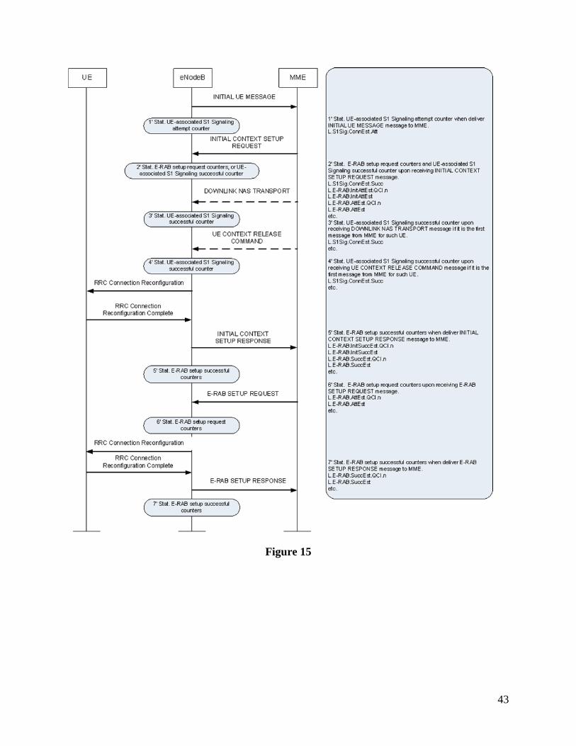
43
Figure 15

44
4.1.2 Call drop Rate (%)
Call drop Rate (%) after change is slightly better than that of before.
The Call Drop Rate KPI indicates the call drop rate of the VoIP services in a cell or radio network.
A VoIP call drop occurs when the VoIP E-RAB is abnormally released. Each E-RAB is associated
with QoS information. Usually, the QCI of VoIP services is 1.
An E-RAB consists of a radio bearer and a corresponding S1 bearer. Any abnormal release of
either bearer causes a call drop. A release is defined as abnormal by its release cause according to
3GPP TS 36.413.
Abnormal E-RAB releases can be classified into the following two scenarios, as shown in Figure
16.

45
Figure 16 [10]
Scenario 1: When the eNodeB sends an E-RAB Release Indication message to the MME, the
abnormal E-RAB release counter is incremented if the bearer to be released carries data and the
release cause is not "Normal Release", "Detach", "User Inactivity", "CS Fallback triggered", "UE
Not Available for PS Service", or "Inter-RAT Redirection".
Scenario 2: When the eNodeB sends a UE Context Release Request message to the MME, the
abnormal E-RAB release counter is incremented if the bearer to be released carries data and the
release cause is not "Normal Release", "Detach", "User Inactivity", "CS fallback triggered", "UE
Not Available For PS Service", "Inter-RAT redirection", "Time Critical Handover", "Handover
Cancelled".
4.1.3 DL Throughput /DL User Edge Throughput (Kbps)
DL Throughput and DL User Edge Throughput after change is better than that of before.
The User Downlink Average Throughput KPI indicates the average downlink UE throughput in a
cell. According to 3GPP TS 32.450, the throughput measurement needs to remove the data
scheduled in the last TTI before the downlink buffer is empty, as shown in Figure 17.

46
Figure 17 Downlink throughput measurement defined in 3GPP TS 32.450
Figure 17 [20]
Below are the detailed results:
Time (ms) Data arrives to empty DL buffer
First data is transmitted to the UE
The send buffer is again empty
The last data unit TTI shall always be removed from calculations since it can be impacted by packet size of User Plane (UP) packets.
ThpTimeDl Failed transmission ( ” Block error ” )
Successful transmission, buffer not empty
Successful transmission, buffer empty
ThpVolDl = ∑
Total DL transferred
volume =
∑
(kbits)
+ (kbits)
IP Throughput in
DL =
ThpVolDl / ThpTimeDl (kbits/s)
No transmission, buffer not empty (e.g. due to contention)
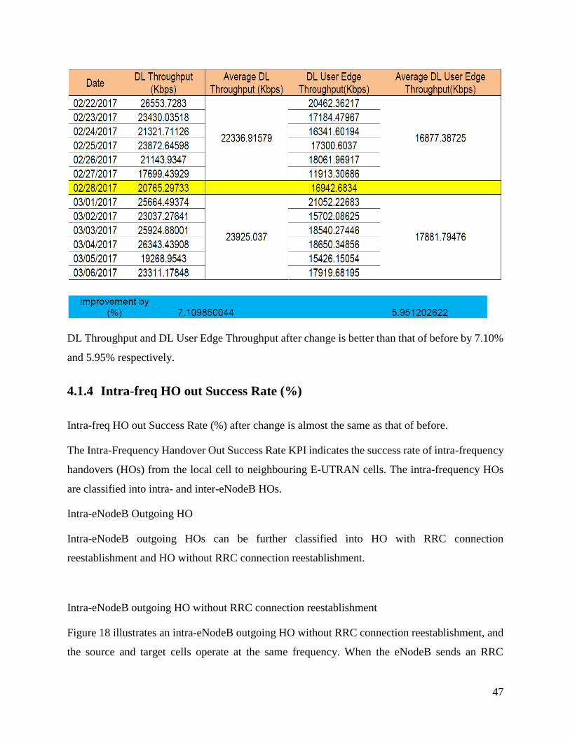
47
DL Throughput and DL User Edge Throughput after change is better than that of before by 7.10%
and 5.95% respectively.
4.1.4 Intra-freq HO out Success Rate (%)
Intra-freq HO out Success Rate (%) after change is almost the same as that of before.
The Intra-Frequency Handover Out Success Rate KPI indicates the success rate of intra-frequency
handovers (HOs) from the local cell to neighbouring E-UTRAN cells. The intra-frequency HOs
are classified into intra- and inter-eNodeB HOs.
Intra-eNodeB Outgoing HO
Intra-eNodeB outgoing HOs can be further classified into HO with RRC connection
reestablishment and HO without RRC connection reestablishment.
Intra-eNodeB outgoing HO without RRC connection reestablishment
Figure 18 illustrates an intra-eNodeB outgoing HO without RRC connection reestablishment, and
the source and target cells operate at the same frequency. When the eNodeB sends an RRC

48
Connection Reconfiguration message containing the handover command to the UE, the eNodeB
counts the number of intra-eNodeB intra-frequency HO outgoing execution attempts in the source
cell at point B. When the eNodeB receives an RRC Connection Reconfiguration Complete
message from the UE, the eNodeB counts the number of successful intra-eNodeB intra-frequency
outgoing HO executions in the source cell at point C. Figure 18 Intra-eNodeB outgoing HO without
RRC connection reestablishment
Figure 18
Intra-eNodeB outgoing HO with RRC connection reestablishment
Figure 19 illustrates an intra-eNodeB outgoing HO with RRC connection reestablishment, and the
source and target cells operate at the same frequency. When the eNodeB sends an RRC Connection
Reconfiguration message containing the handover command to the UE, the eNodeB counts the
number of intra-eNodeB intra-frequency outgoing HO execution attempts in the source cell at
point B. When the eNodeB receives an RRC Connection Reestablishment Complete message from
the UE, the eNodeB counts the number of successful intra-eNodeB intra-frequency outgoing HO
executions in the source cell at point C.
Figure 19 Intra-eNodeB outgoing HO with RRC connection reestablishment.

49
Figure 19
4.2 Summary
The results shared in this chapter clearly show that using CoMP does improve cell edge
user performance. The KPIs we used to quantitatively provide visibility into the so call “user
experience”. That is, E-RAB success rate indicates that a user can at least access service.
Throughput shows what the bandwidth (in bps) what a user can reach. The call drop rate and intra-
frequency is an indication of service continuity.

50
Chapter 5
5 Conclusion and Recommendations
5.1 Conclusion
From the drive tests measurements, it is concluded that after activating DL CoMP feature for the
3 sites, data throughput was significantly improved, that is, the DL throughput and DL Edge user’s
throughput.
It is therefore evident from the measurement results that the cooperative multipoint feature
improves data throughput for users (especially cell edge users who experience a lot of interference)
as well as providing a better user experience in terms of call drop rate reduction. As evidenced by
the measurement results carried over twelve days the overall main KPIs of those sites with the
CoMP feature enabled, the performance of the network significant improved.
However, since this is a live commercial network we had to be cautious in terms disrupting
customers’ services, that is, not to cause significant downtime. We therefore could not manage all
CoMP parameters as to evaluate the maximum performance improvement we can achieve with
this feature.
Some of the parameters are specified in the 3GPP TS 36.331 and 3GPP TS 36.413 specification
documents. For example, in our measurements we only used ideal backhaul which is 10Gigabits
in capacity using optic fibre. Given time and opportunity it will be interesting to compare the
results of ideal and non-ideal backhaul, when HARQ is activated and deactivated, etc.
Also, dependent on the proximity of the base stations it is also interesting to measure the backhaul
overhead load when more cells are added into clusters. This is also dependent on the initial phase
of RF planning which determines the extent of coverage overlap among the cells.
Even with these parameters enabled or disabled, the parameters also have extensive options
associated with them leading us to the recommendations made below.
5.2 Recommendation
I recommend that since the CoMP feature has a lot switches involved a test bed is very crucial in
extensively playing around with the switched/parameters and their associated options to provide

51
“best practices” reports or documents as what is produced by other internet bodies like the IETF,
Regional Network Organizations, e.g. AFNOG, RIPE, NANOG, etc. Such best practices
documents will point out the main parameters and recommended options and option values for
different LTE network deployment scenarios.
52
References
[1] J. Lee, Y. Kim, H. Lee, B. Ng, D. Mazzarese, J. Liu, W. Xiao and Y. Zhou, "Coordinated
multipoint transmission and reception in LTE-advanced systems", IEEE Communications
Magazine, vol. 50, no. 11, pp. 44-50, 2012.
[2] 3rd Generation Partnership Project; Technical Specification Group Services and System
Aspects; Telecommunication management; Key Performance Indicators (KPI) for Evolved
Universal Terrestrial Radio Access Network (E-UTRAN); Requirements (Release 14), 3GPP TS
32.451 V14.0.0 (2017-04)
[3] C. Shannon, "A Mathematical Theory of Communication", Bell System Technical Journal, vol.
27, no. 3, pp. 379-423, 1948.
[4] 3rd Generation Partnership Project; Technical Specification Group Radio Access Network;
Evolved Universal Terrestrial Radio Access (E-UTRA); Multiplexing and channel coding
(Release 14). 3GPP TS 36.212 V14.3.0 (2017-06)
[6]3GPP, 3rd generation partnership project; Technical specification group radio access network;
Requirements for Evolved UTRA (E-UTRA) and Evolved UTRAN (E-UTRAN) (Release 7),
3GPP TR 25.913
[7] S. Ahmadi, LTE-Advanced, 1st ed. Elsevier Science, 2013.
[8] 3rd Generation Partnership Project; Technical Specification Group Radio Access Network;
Evolved Universal Terrestrial Radio Access Network (E-UTRAN); S1 Application Protocol
(S1AP) (Release 14); 3GPP TS 36.413 V14.3.0 (2017-06)
[9] 4G Americas 3GPP Release 12 Executive Summary February 2015
[10] M. Ali, "On the Evolution of Coordinated Multi-Point (CoMP) Transmission in LTE-
Advanced", International Journal of Future Generation Communication and Networking, vol. 7,
no. 4, pp. 91-102, 2014.
[11] D. Lee, H. Seo, B. Clerckx, E. Hardouin, D. Mazzarese, S. Nagata and K. Sayana,
"Coordinated multipoint transmission and reception in LTE-advanced: deployment scenarios and
operational challenges", IEEE Communications Magazine, vol. 50, no. 2, pp. 148-155, 2012.

53
[12] 3GPP TR 36.819 V11.1.0 (2011-12)
[13] J. Litva and T. Lo, Digital beamforming in wireless communications, 1st ed. Boston, Mass:
Artech House, 1996.
[14] E. Dahlmann, S. Parkvall and J. Skold, 4G: LTE/LTE-advanced for mobile broadband, 1st
ed. Amsterdam: Elsevier, Academic Press, 2014.
[15] L. Hanzo, M. Munster, B. Choi and T. Keller, OFDM and MC-CDMA for Broadband Multi-
User Communications, WLANs and Broadcasting, 1st ed. New York, NY: John Wiley & Sons,
2005.
[16] D. Lee, H. Seo, B. Clerckx, E. Hardouin, D. Mazzarese, S. Nagata and K. Sayana,
"Coordinated multipoint transmission and reception in LTE-advanced: deployment scenarios and
operational challenges", IEEE Communications Magazine, vol. 50, no. 2, pp. 148-155, 2012.
[17] 3rd Generation Partnership Project; Technical Specification Group Radio Access Network;
Coordinated multi-point operation for LTE with non-ideal backhaul (Release 12). 3GPP TR36.874
V12.0.0 (2013-12)
[18] https://iperf.fr/
[19] 3rd Generation Partnership Project; Technical Specification Group Radio Access Network;
Evolved Universal Terrestrial Radio Access (E-UTRA); Radio Resource Control (RRC); Protocol
specification (Release 14); 3GPP TS 36.331 V14.4.0 (2017-09)
[20] 3rd Generation Partnership Project; Technical Specification Group Services and System
Aspects; Telecommunication management; Key Performance Indicators (KPI) for Evolved
Universal Terrestrial Radio Access Network (E-UTRAN): Definitions (Release 14); 3GPP TS
32.450 V14.0.0 (2017-04)
[21] Network Coordination for Spectrally Efficient Communications In Wireless Networks, by M.
Kemal Karakayali
[22] P. Marsch and G. Fettweis, Coordinated multi-point in mobile communications, 1st ed.
Cambridge: Cambridge University Press, 2011. ISBN 978-1-107-00411-5

54
[23] R. Irmer, H. Droste, P. Marsch, M. Grieger, G. Fettweis, S. Brueck, H. Mayer, L. Thiele and
V. Jungnickel, "Coordinated multipoint: Concepts, performance, and field trial results", IEEE
Communications Magazine, vol. 49, no. 2, pp. 102-111, 2011.
[24] A. Paulraj, R. Nabar and D. Gore, Introduction to space-time wireless communications, 1st
ed. Cambridge: Cambridge University Press, 2008.
[25] Mohammad T. Kawser, Nafiz Imtiaz Bin Hamid, Md. Nayeemul Hasan, M. Shah Alam, &
M. Musfiqur Rahman, “Downlink SNR to CQI Mapping for Different Multiple Antenna
Techniques in LTE”, International Journal of Information and Electronics Engineering, Vol. 2,
No. 5, September 2012
[26] Matthias Fricke, Andrea Heckwolf, Ralf Herber, et. Al. Requirements of 4G-Based Mobile
Broadband on Future Transport Networks, 2012.
[27] 3rd Generation Partnership Project; Technical Specification Group Radio Access Network;
Evolved Universal Terrestrial Radio Access (E-UTRA); Physical channels and modulation
(Release 14). 3GPP TS 36.211 V14.1.0 (2016-12)