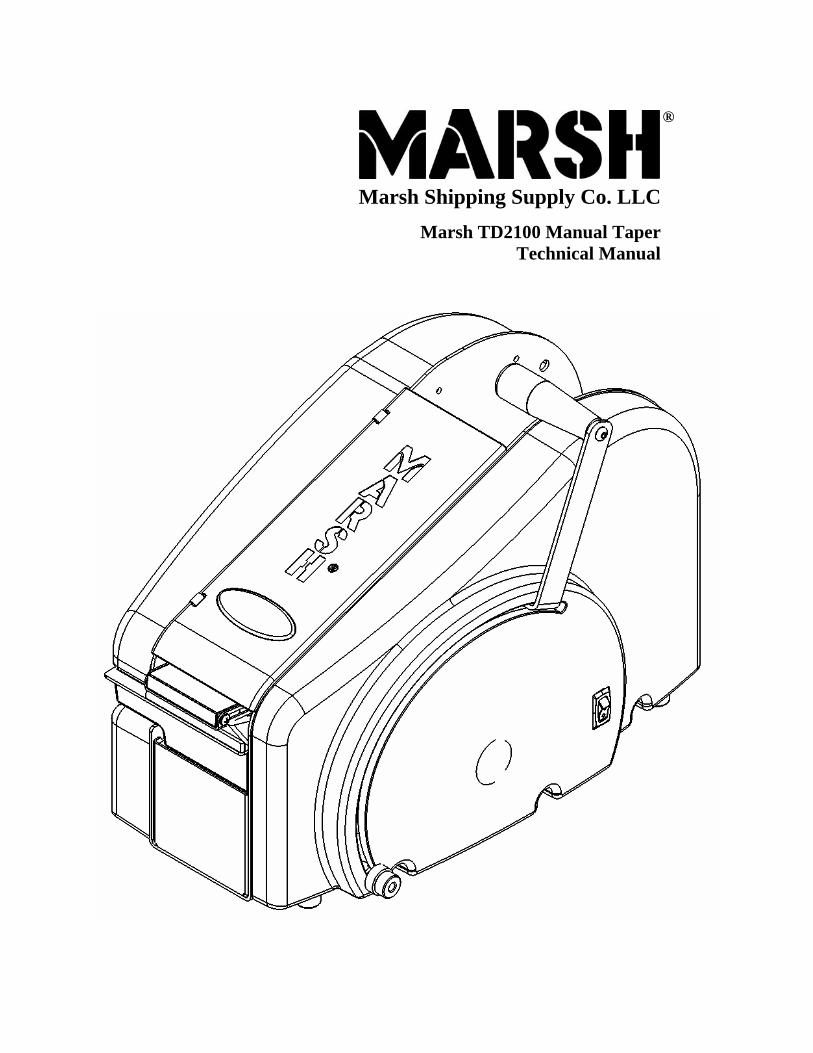
marsh td2100 manual taper technical manual
TRANSCRIPT
®
Marsh Shipping Supply Co. LLC
Marsh TD2100 Manual TaperTechnical Manual

2
20/2006
Marsh Shipping Supply Co. LLC; Collinsville, IL 62234 U.S.A.; Tel: 618.343.1006 Fax: 618.343.1016 41910 12/
A wall-socket must be close to the product and readily accessible. The overall system is protected against overload by the branch circuit protection in accordance with the current edition of the NEC or CEC
Table of Contents
Introduction Specifications Setup Instructions Operating Instructions Maintenance Troubleshooting The 12 machine will not feed tape. The 13 ON/OFF switch is not illuminated. The 14 tape slips at the feed wheel. The 14 cutter doesn’t cut the tape. The 14 handle will not or is difficult to pull forward. The 15 tape is jamming or tearing. The 15 tape is cut, but the cutter blades don’t return to neutral position. The 15 tape is not the correct length. The 16 tape doesn’t stick to the carton. The 16 tape slips on the carton. The 17 heater doesn’t heat. Repair Rem 19 oving the Handle Attac 19 hing the Handle Rem 20 oving the Right Side Cover Attac 20 hing the Right Side Cover Rem 22 oving the Left Side Cover Attac 22 hing the Left Side Cover Rem 24 oving the Cutter Return Spring Attac 24 hing the Cutter Return Spring Rem 26 oving the Pinch Roller Attac 26 hing the Pinch Roller Rem 28 oving the Weighted Brush Cover Attac 28 hing the Weighted Brush Cover Rem 30 oving the Tape Channel Plate Attac 30 hing the Tape Channel Plate Rem 32 oving the Tape Basket/Motor Cover Attac 32 hing the Tape Basket/Motor Cover Rem 34 oving the Water Tank Holder Attac 34 hing the Water Tank Holder Rem 36 oving the Cutter Arms Attac 36
4 5 6 9 9 12
18
hing the Cutter Arms

Marsh Shipping Supply Co. LLC; Collinsville, IL 62234 U.S.A.; Tel: 618.343.1006 Fax: 618.343.1016
3
41910 12/20/2006
Rem 38 oving the Movable Cutter Assembly Attac 38 hing the Movable Cutter Assembly Rem 40 oving the Idler Gear Attac 40 hing the Idler Gear Rem 41 oving the Drive Gear with Springs and Clutch Assembly Attac 41 hing the Drive Gear with Springs and Clutch Assembly
Separating the Drive Gear with Springs and Clutch Assembly Removing the Gearbox/Motor Mount
Attac 43 hing the Gearbox/Motor Mount Repl 45 acing the Movable Cutter Blade Replacing the Brush Replacing the Thermostat Assembly
Replacing the Front Cover Replacing the Top Roller Replacing the Free Spin Roller Assembly Replacing the Ramp Replacing the Tape Guide Assembly Replacing the Fixed Blade Replacing the Feed Wheel Replacing the Handle Shaft Parts List Wiring Diagram Addendum Rem 67 oving the Weighted Brush Cover Attac 67 hing the Weighted Brush Cover Repl 69
41 43
46 46 48 48 50 50 52 52 54 56
58 66 67
acing the Slide Roller

Mar
4
Introduction
Congratulations on the purchase of your new MARSH TD2100 gummed tape dispenser from MARSH SHIPPING SUPPLY CO., LLC. We are confident you will be very pleased with the operation and performance of this durable, quality built machine for many yearsto come. The TD2100 Manual Taper Technical Manual provides the necessary information about the operation, maintenance, and repair of your new tape dispenser. However, Marsh does have a policy of continual product improvement. So, Marsh reserves the right to modify the information contained within the manual without prior notice. The setup section was designed to simplify the setup of the machine and to allow you to get the machine up and running so that it can do what it is supposed to do… dispense gummed tape quietly, quickly, and accurately. The operating section provides information on the operation of the machine. The maintenance section provides information about required care and maintenance of the machines and further adjustments if required for your particular use. This technical manual provides a troubleshooting section to help you with possible operating problems and corrective actions. Should you require replacement parts, pleaserefer to the provided parts list. Should you need assistance, or if you would like to obtain information about any Marsh product, contact your Marsh distributor or Marsh Shipping Supply Company, LLC at: Marsh Shipping Supply Company, LLC Address: 926 McDonough Lake Road Collinsville, IL 62234 USA Telephone: (618)-343-1006 Fax: (618)-343-1016 E-mail: [email protected]: www.marshship.com Technical Support Telephone: (573)-437-7030 Fax: (573)-437-4030
sh Shipping Supply Co. LLC; Collinsville, IL 62234 U.S.A.; Tel: 618.343.1006 Fax: 618.343.1016 41910 12/20/2006

Mar
5
Specifications
Net and Shipping Weight: 23 pounds (10.4 kg); 29 pounds (13.2 kg) Water Bottle Capacity: 70 ounces (2070 ml) Tape: Dry gummed tape – paper or reinforced – between 1 to 3
inches (25.4 to 76.2 mm) wide, up to 1000 feet (304.8 m) longand 9 inches (228.6 mm) max roll diameter
For Units with Heater:
Electrical Requirements: 115 volts AC or 220 volts AC 50/60 Hz 4 amps at 115 volts 2 amps at 220 volts
Power Cord Length: 7 feet (2.3 m) Dimensions:
sh Shipping Supply 12/20/2006
18.9 in 48.0 cm
13.7 in 34.8 cm
10.5 in 26.6 cm
Figure 1 – Tape Machine Dimensions
Co. LLC; Collinsville, IL 62234 U.S.A.; Tel: 618.343.1006 Fax: 618.343.1016 41910
6
Setup Instructions
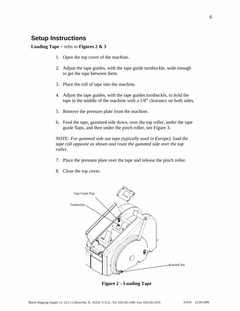
Loading Tape – refer to Figures 2 & 31. Open the top cover of the machine.
2. Adjust the tape guides, with the tape guide turnbuckle, wide enough to get the tape between them.
3. Place the roll of tape into the machine.
4. Adjust the tape guides, with the tape guides turnbuckle, to hold the
tape in the middle of the machine with a 1/8” clearance on both sides.
5. Remove the pressure plate from the machine.
6. Feed the tape, gummed side down, over the top roller, under the tape guide flaps, and then under the pinch roller, see Figure 3.
NOTE: For gummed side out tape (typically used in Europe), load the tape roll opposite as shown and route the gummed side over the top roller.
7. Place the pressure plate over the tape and release the pinch roller.
8. Close the top cover.
Tape Guide Flap
Turnbuckle
Knurled Nut
Figure 2 – Loading Tape
Marsh Shipping Supply Co. LLC; Collinsville, IL 62234 U.S.A.; Tel: 618.343.1006 Fax: 618.343.1016 41910 12/20/2006
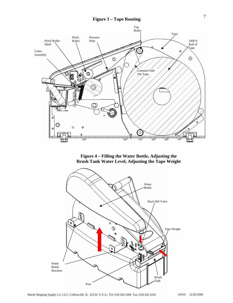
7Figure 3 – Tape Routing
B t
Cutter Assembly
1
R T
r
Water Bottle Brackets
Marsh Shipping Supply Co. LLC; Collins
Figure 4 – Filling the Water Bottle, Adjusting the rush Tank Water Level, Adjusting the Tape Weigh
PinchRoller
ville, IL
Pressure Plate
62234 U.S.A.; Tel: 618.343.1006 F
Top Rolle
ax: 618.343.1016
Tape
Gummed Side Out Tape
41910
000 ftoll ofape
Pinch RollerShaft
Tape Weight
Water Bottle
Duck Bill Valve
Post
BrushTank
12/20/2006

Marsh Ship
8
Filling the Water Bottle – Figure 4
1. Remove the water bottle from the machine.
2. Remove the duckbill valve from the water bottle.
3. Fill the water bottle with water.
4. Place the duckbill valve back into the water bottle.
5. Place the water bottle back onto the machine; verify that the post in thebrush tank is inserted through the duckbill valve.
ping Supply Co. LLC; Collinsville, IL 62234 U.S.A.; Te
W t
Adjusting the Brush Tank Water L
1. Loosen the retaining screws o
2. Move the water bottle bracketdesired water level in the brustypically be set at the low posi
3. Both brackets should be at the
4. Tighten the retaining screws o
Adjusting the Tape Weight – Figur
1. Loosen the retaining screw.
2. Slide the tape weight forward more water to the tape, and is
3. Slide the tape weight back for
water to the tape, and is typica
4. Tighten the retaining screw.
Figure 5 – Adjustable Water Level Positions
Low
High Medium
evel – refer to Figures 4 and 5
n the water bottle brackets.
s to the desired position to obtain the h tank. Light weight tapes would tion (Figure 5).
same position.
n the water bottle brackets.
e 4
for greater pressure. This is will applytypically used on heavy weight tapes.
less pressure. This is will apply less lly used on lighter weight tapes.
l: 618.343.1006 Fax:
ater Bottle Bra cke
618.343.1016 41910 12/20/2006

9
Operating Instructions
Once the machine has been properly setup for use, pull the operating handle to the desired
length that is on the scale and release the handle, when the handle returns to the resting
position the tape will be cut. The mechanical stop is provided on the side of the machine
(Figure 2) to be used if a known length will be used repeatedly. The mechanical stop can
moved to the desired position by loosening the knurled nut a half of a turn and sliding up
or down the slot in the machine and retightening.
Caution: The knurled nut should never be removed.
Maintenance
The Marsh TD2100 requires very little maintenance, but it is important to regularly clean the brush, brush tank, cutter mechanism, and remove debris from the tape path. CAUTION: Before beginning maintenance or adjustments be sure the tape machine is turned off and unplugged. Cleaning Water Feed System
1. Turn the power switch to the OFF position and unplug the power cord.
2. Clean the brush by soaking it in warm soapy water and then rinse.
3. Clean the brush tank by rinsing it with warm water.
4. Rinse out the water bottle and duckbill valve with warm water.
Marsh Shipping Supply Co. LLC; Collinsville, IL 62234 U.S.A.; Tel: 618.343.1006 Fax: 618.343.1016 41910 12/20/2006

10
Cutter Guard
Water Tank Holder
Cleaning Gaps
Weight Brush Tank Cover
P
Top Cover
Cutter Assembly
Figure 5 – Cleaning the Cutter
Marsh Shipping Supply Co. LLC; Collinsville, IL 62234 U.S.A.; Tel:
Tape Channel
e
ressure PlatAssembly, Cleaning the Tape Path
Cleaning the Cutter Assembly – Figure 5
1. Turn the power switch to the OFF position and unplug the power cord.
2. Open top cover.
3. Remove pressure plate.
4. Remove the tape from the tape path.
5. Using minimal amount of a non-flammable lubricant (MG Chemicals Super PenetratingLubricant [www.mgchemicals.com], WD 40, or Marsh Industrial Silicon Spray are recommended), spray the cutter assembly behind the cutter guard, using the available gaps in front and behind the cutter guard. Allow the lubricant to dry or wipe dry.
618.343.1006 Fax: 618.343.1016 41910 12/20/2006

Marsh Shipping Supply Co. LLC; Collinsville, IL 62234 U.S.A.; Tel: 618.343.1006 Fax: 618.343.1016
11
41910 12/20/2006
Cleaning the Tape Path – Figure 5
1. Turn the power switch to the off position and unplug the power cord.
2. Open the top cover.
3. Remove pressure plate.
4. Remove tape from tape path.
5. Using compressed air remove all debris form the tape path.
6. Using a moist cloth wipe down all sheet metal parts within tape path (tape channel, pressure plate, weighted brush tank cover, and water tank holder) to remove debris and adhesive build-up.
7. Using compressed air remove any visible moisture from the tape path.
8. Referring to the tape loading section on pg. 6. Place the tape back into the tape path.
9. Place the pressure plate back in the machine.
10. Close the top cover.

Marsh Shipping Supply Co. LLC; Collinsville, IL 62234 U.S.A.; Tel: 618.343.1006 Fax: 618.343.1016
12
41910 12/20/2006
Possible Cause: Solution:
1. Is the path of the tape blocked?
2. Is the path of the tape dirty?
3. Are the tape guides set correctly?
4. Is the tape routed correctly? 5. Is the feed wheel set screw
loose?
1. Clear all debris from the path of the tape. Ensure clearance at:
a. the blades b. feed wheel
Refer to Maintenance (p. 9).
2. Remove the pressure plate, remove all debris from the tape with a damp cloth, and then replace the pressure plate. Refer to Maintenance (p. 9).
3. Adjust the tape guide turnbuckle to ensure a 1/8” gap on each side of the tape roll.
4. Route the tape according to Fig 3
(p. 7).
5. Make sure the feed wheel is in the correct position, and then tighten the feed wheel set screw (refer to Removing the Tape Channel Plate [p. 30] to gain access to the feed wheel set screw).
Problem: The machine will not feed the tape.
Troubleshooting
This section describes potential problems you may encounter while working with your TD2100 tape machine and outlines possible causes and solutions for these problems. To avoid problematic situations, be sure to follow the procedures in the setup and maintenance sections. For units with a heater, be sure to turn the power OFF, and disconnect from power source before performing any repairs. For further assistance please contact your Marsh distributor or Marsh Shipping Supply Co. LLC technical support at;
Telephone: (573)-437-7030 Fax: (573)-437-4030
Email: [email protected]
Marsh Shipping Supply Co. LLC; Collinsville, IL 62234 U.S.A.; Tel: 618.343.1006 Fax: 618.343.1016
13
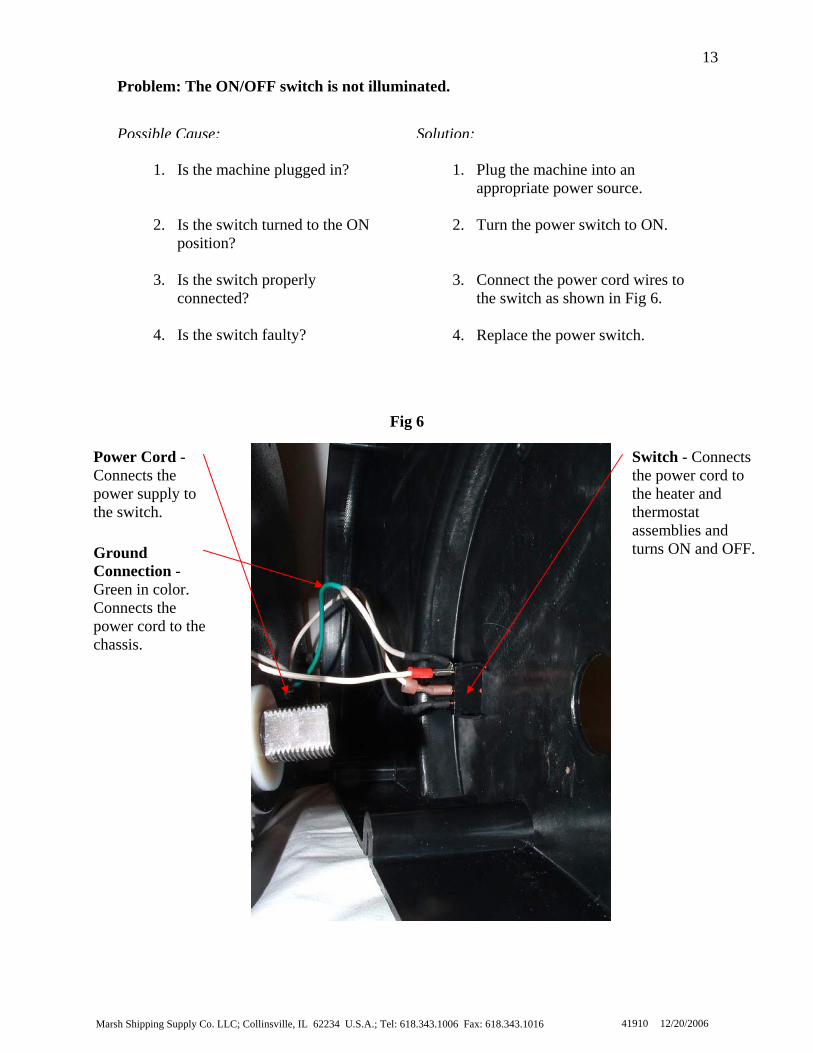
41910 12/20/2006
Power Cord - Connects the power supply to the switch.
Switch - Connects the power cord to the heater and thermostat assemblies and turns ON and OFF.
Fig 6
Solution:Possible Cause:
1. Is the machine plugged in?
2. Is the switch turned to the ON position?
3. Is the switch properly
connected?
4. Is the switch faulty?
1. Plug the machine into an appropriate power source.
2. Turn the power switch to ON.
3. Connect the power cord wires to the switch as shown in Fig 6.
4. Replace the power switch.
Problem: The ON/OFF switch is not illuminated.
Ground Connection - Green in color. Connects the power cord to the chassis.

Marsh Shipping Supply Co. LLC; Collinsville, IL 62234 U.S.A.; Tel: 618.343.1006 Fax: 618.343.1016
14
41910 12/20/2006
1. Replace the cutters. Refer to Replacing the Movable Cutter Blade (p. 45) and/or Replacing the Fixed Blade (p. 52).
2. Tighten the feed wheel set screw
(refer to Removing the Tape Channel Plate [p. 30] to gain access to the feed wheel set screw).
3. Replace the clutch. Refer to
Replacing the Drive Gear with Spring and Clutch Assembly (p. 41).
1. Are the blades of the cutter dull or worn?
2. Is the feed wheel set screw
loose? 3. Are the clutch bearings bad?
Solution:Possible Cause:
Problem: The handle is either difficult to or won’t pull forward
Possible Cause: Solution:
1. Is the cutter clean?
2. Are the blades of the cutter dull or worn?
1. Clean the cutter blades. Refer to Maintenance (p. 9).
2. Replace the cutters. Refer to
Replacing the Movable Cutter Blade (p. 45) and/or Replacing the Fixed Blade (p. 52).
Problem: The cutter doesn’t cut the tape.
Problem: The tape slips at the feed wheel.
Possible Cause: Solution:
1. Is the feed wheel dirty?
2. Is the feed wheel set screw loose?
1. Remove any tape from the machine, and whipe the feed wheel with a damp cloth.
2. Tighten the feed wheel set screw
(refer to Removing the Tape Channel Plate [p. 30] to gain access to the feed wheel set screw).
Marsh Shipping Supply Co. LLC; Collinsville, IL 62234 U.S.A.; Tel: 618.343.1006 Fax: 618.343.1016
15
41910 12/20/2006
1. Clean the feed wheel. Check to see if the feed wheel is spinning on the feed wheel shaft. If the feed wheel is spinning on the feed wheel shaft, tighten the set screws on the feed wheel (refer to Removing the Tape Channel Plate [p. 30] to gain access to the feed wheel set screw).
1. Is the tape the wrong length?
Possible Cause: Solution: NOTE: Accuracy ± 1/2”
1. Clean the cutter blades. Refer to Maintenance (p. 9).
1. Are the cutter blades clean? Problem: The tape is not the correct length.
Problem: The tape is jamming or tearing.
Possible Cause: Solution:
1. Is the pressure plate all the way to the pinch roll shaft?
2. Is the brush installed correctly?
3. Are the tape guides spaced
correctly?
1. Place the pressure plate all the way down to the pinch roll shaft and make sure the pressure plate lays flat.
2. Install the brush correctly. Refer
to Replacing the Brush (p. 46).
3. Adjust the tape guides to have a 1/8” gap on each side of the tape.
Problem: The tape is cut, but the cutter blades don’t return to the neutral position
Possible Cause: Solution:
Marsh Shipping Supply Co. LLC; Collinsville, IL 62234 U.S.A.; Tel: 618.343.1006 Fax: 618.343.1016
16
41910 12/20/2006
Problem: The tape slips on the carton.
Possible Cause: Solution:
1. Is the tape too wet?
2. Are the cartons dirty?
1. Adjust the water level and/or the tape weight.
2. The cartons need to be free of
dust and dirt for proper adhesion.
Problem: The tape doesn’t stick to the carton.
Possible Cause: Solution:
6. See the trouble shooting section for The heater doesn’t heat (p. 17).
5. The cartons need to be free of dust and dirt for proper adhesion.
4. Adjust the tape weight accordingly.
3. If the bristles do not extend above the top of the brush tank, the brush needs to be replaced.
1. Fill the water bottle.
2. Clean the brush.
1. Is the water bottle full?
2. Is the brush clean?
3. Are the brush bristles worn?
4. Is there the correct amount of pressure on the tape?
5. Are the cartons dirty?
6. Is the water being heated? (Only if you have a heated model of the TD2100 HT)

Marsh Shipping Supply Co. LLC; Collinsville, IL 62234 U.S.A.; Tel: 618.343.1006 Fax: 618.343.1016
17
41910 12/20/2006
1. Plug the machine into an appropriate power source.
2. Turn the power switch to ON.
3. Tighten the screws holding the
thermostat on (refer to Replacing the Thermostat Assembly and Fig 30 [p. 46]).
4. Connect all wires as shown in Fig
6 (p. 13).
5. You need to replace the heater assembly. Refer to Removing the Water Tank Holder (p. 34).
6. You may need to replace the
thermostat assembly. Refer to Replacing the Thermostat Assembly (p. 46).
7. You may need to replace the
heater assembly. Refer to Removing the Water Tank Holder and Attaching the Water Tank Holder (p. 34).
1. Is the machine plugged in?
2. Is the machine turned on?
3. Is the thermostat securely attached?
4. Is the heater connected properly?
5. Are the wires connected to the
heater?
6. Is the thermostat faulty?
7. Is the heater faulty?
Possible Cause: Solution:
Problem: The heater doesn’t heat.

Marsh Shipping Supply Co. LLC; Collinsville, IL 62234 U.S.A.; Tel: 618.343.1006 Fax: 618.343.1016
18
Fig 7
When attempting any repairs to the TD 2100, certain tools make the disassembly and reassembly of the TD 2100 easier (Fig 13). Below is a list of the tools that are recommended for the disassembly and assembly of the TD 2100.
When attempting any repairs involving steel sheet metal pieces, do not over tighten the screws. The screws are to keep the part in place not to provide structural support. The screws should be snug, not tight.
Tools for Repair
For any Repairs involving Aluminum Sheet Metal
For any Repairs
To attempt any repairs, the foot channels should be loosened (Fig 7). This allows the chassis to “relax.” If the foot channels are not loosened, taking apart the machine will be difficult and may not reassemble together correctly.
Repair
41910 12/20/2006
Loosen both screws on the bottom of the chassis.
Fig 8
3/8” flat head screw driver #2 4” Phillips head screw driver #2 8” Phillips head screw driver Needle nose pliers Vice grips 5/16" wrench or socket3/8” wrench or socket 7/16” wrench or socket 1/2” wrench or socket 15/16" socket
3/32” long hex key 5/64” hex key 1/8” hex key 3/16” hex key 1/4” hex key

19
4. Rotate the handle forward to about the 12 inch mark on
Attaching the Handle To attach the handle, see Fig 9 and follow the steps below.
1. Insert the handle into the right side cover at the 12 inch mark on the
right side cover. 2. Rotate the handle so that the hole in the handle and the handle shaft
line up. 3. Slide the handle onto the handle shaft. 4. Attach the 15/16 inch nut. 5. Attach the handle hole plug.
The machine is now ready to continue normal operation.
Removing the Handle To remove the handle, see Fig 9 and follow the steps below.
1. Remove the handle hole plug. 2. Remove the 15/16 inch nut. 3. Slide the handle OFF of the handle shaft. 4. Rotate the handle forward to about the 12 inch mark on the right side
cover and pull the handle gently from the machine. The handle is now removed. At this point a handle may be installed.
Fig 9 Handle
2. Remove the 15/16 inch nut.
3. Slide the handle OFF ofthe handle shaft.Marsh Shipping Supply Co. LLC; Collinsville, IL 62234 U.S.A.; Tel: 618.343.1006 Fax: 618.343.1016 41910 12/20/2006
the right side cover and pull the handle gently from the machine.
20
6
To attach the right side cover, see Fig 6, Fig 10, and follow the steps below.
1. Bring the right side cover close enough to attach the power wires to the switch.
2. Attach the power wires. 3. Place the handle in the slot of the right side cover and slide the
handle onto the handle shaft. 4. Attach the three screws along the outside of the machine. 5. Attach the three screws along the inside of the machine. 6. Attach the 15/16 inch nut to the handle shaft. 7. Attach the handle hole plug. 8. Close the top cover. 9. Place the water tank and brush into the water tank holder. 10. Place the water bottle and duckbill valve onto the water bottle
brackets with the post of the water tank into the duckbill valve. The machine is now ready to continue normal operation.
Attaching the Right Side Cover
To remove the right side cover, see Fig 10 and follow the steps below.
1. Turn the switch to OFF and unplug the machine. 2. Remove the water bottle and duckbill valve. 3. Remove the water tank and brush. 4. Open the top cover. 5. Remove the handle hole plug. 6. Remove the 15/16 inch nut from the handle shaft. 7. Remove the three screws along the inside of the machine. 8. Remove the three screws along the outside of the machine. 9. Slide the handle to the end of the handle shaft and slowly remove
the right side cover with the handle.
CAUTION: There are several wire connections made between the chassis and the right side cover. Do not damage these connections.
NOTE: For light maintenance, only disconnect the top wire from the inside of the right cover. Place the right side cover at the back of the machine. To reattach the right side cover from this point, refer to step 3 of Attaching the Right Side Cover.
10. Remove the power wires from the ON/OFF switch, noting the
color and connection configuration. The right side cover is now completely removed from the chassis. At this point a new right side cover may be installed.
Removing the Right Side Cover
Marsh Shipping Supply Co. LLC; Collinsville, IL 62234 U.S.A.; Tel: 618.343.1006 Fax: 618.343.1016 41910 12/20/200
Marsh Sh
21
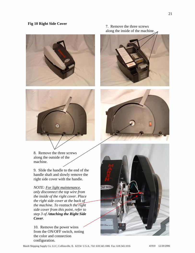
7. Remove the three screws along the inside of the machine.
Fig 10 Right Side Cover
8. Remove the three screws along the outside of the machine.
9. Slide the handle to the end of the handle shaft and slowly remove the right side cover with the handle.
NOTE: For light maintenance, only disconnect the top wire from the inside of the right cover. Place the right side cover at the back of the machine. To reattach the right side cover from this point, refer to step 3 of Attaching the Right Side Cover. 10. Remove the power wires from the ON/OFF switch, noting the color and connection configuration.
ipping Supply Co. LLC; Collinsville, IL 62234 U.S.A.; Tel: 618.343.1006 Fax: 618.343.1016 41910 12/20/2006
Marsh Shipping Supply Co. LLC; Collinsville, IL 62234 U.S.A.; Tel: 618.343.1006 Fax: 618.343.1016
22
41910 12/20/2006
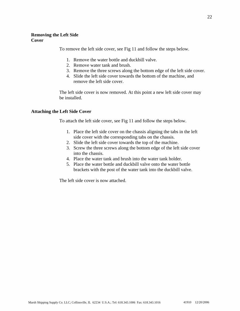
Attaching the Left Side Cover
To attach the left side cover, see Fig 11 and follow the steps below.
1. Place the left side cover on the chassis aligning the tabs in the left side cover with the corresponding tabs on the chassis.
2. Slide the left side cover towards the top of the machine. 3. Screw the three screws along the bottom edge of the left side cover
into the chassis. 4. Place the water tank and brush into the water tank holder. 5. Place the water bottle and duckbill valve onto the water bottle
brackets with the post of the water tank into the duckbill valve. The left side cover is now attached.
Removing the Left Side Cover
To remove the left side cover, see Fig 11 and follow the steps below.
1. Remove the water bottle and duckbill valve. 2. Remove water tank and brush. 3. Remove the three screws along the bottom edge of the left side cover. 4. Slide the left side cover towards the bottom of the machine, and
remove the left side cover. The left side cover is now removed. At this point a new left side cover may be installed.
Marsh Shipping Supply Co. LLC; Collinsville, IL 62234
23
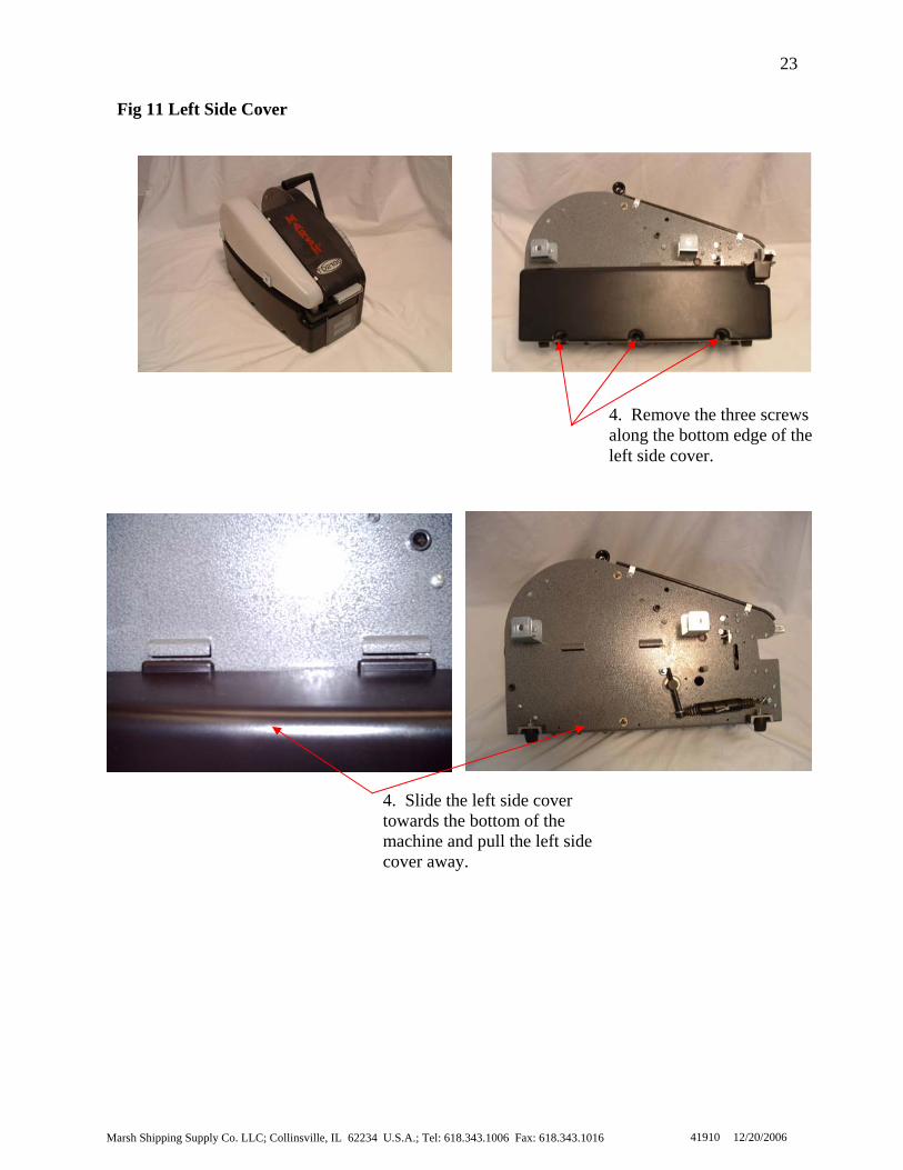
Fig 11 Left Side Cover
4. Remove the three screws along the bottom edge of the left side cover.
4. Slide the left side cover towards the bottom of the machine and pull the left side cover away.
U.S.A.; Tel: 618.343.1006 Fax: 618.343.1016 41910 12/20/2006

Marsh Shipping Supply
24
Attaching the Cutter Return Spring
Removing the Cutter Return Spring
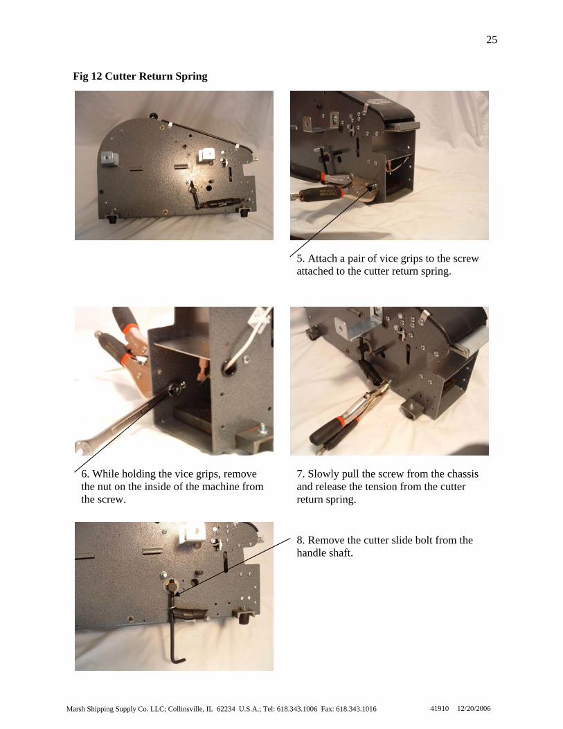
To remove the cutter return spring, see Fig 12 and follow the steps below.
1. Turn the switch to OFF and unplug the machine. 2. Remove the right side cover (refer to Removing the Right Side
Cover [p. 20]). 3. Remove the left side cover (refer to Removing the Left Side Cover
[p. 22]). 4. Remove the four screws from the front cover and remove the front
cover. 5. Attach a pair of vice grips to the screw attached to the cutter return
spring. 6. While holding the vice grips, remove the nut on the inside of the
machine from the screw. 7. Slowly pull the screw from the chassis and release the tension from
the cutter return spring. 8. Remove the cutter slide bolt from the handle shaft.
The cutter return spring is now removed. At this point a new cutter return spring may be installed.
To attach the cutter return spring, see Fig 12 and follow the steps below.
1. Put the S-hook of the cutter return spring onto the cutter slide bolt then slide a washer onto the cutter slide bolt.
2. Attach the cutter slide bolt to the handle shaft. 3. Slide the end of the spring onto the screw and then attach the nut to
the screw. 4. Attach a pair of vice grips to the screw, and pull the spring until the
screw is in the correct hole in the chassis. 5. While holding the spring stretched with the vice grips, attach the
other nut to the screw. 6. Position the front cover into place and attach four screws to the front
cover. 7. Attach the left side cover (refer to Attaching the Left Side Cover [p.
22]). 8. Attach the right side cover (refer to Attaching the Right Side Cover
[p. 20]). The machine is now ready to continue normal operation.
Co. LLC; Collinsville, IL 62234 U.S.A.; Tel: 618.343.1006 Fax: 618.343.1016 41910 12/20/2006
Ma
25
5. Attach a pair of vice grips to the screw attached to the cutter return spring.
Fig 12 Cutter Return Spring
6. While holding the vice grips, remove the nut on the inside of the machine fromthe screw.
rsh Shipping Supply Co. LLC; Collinsville, IL 62234 U.S.A.; Tel: 618.3
7. Slowly pull the screw from the chassis and release the tension from the cutter return spring.
43.1006 Fax: 618.343.1016 41910 12/20/2006
8. Remove the cutter slide bolt from the handle shaft.
Marsh Shipping Supply Co. LLC; Collinsville, IL 62234 U.S.A.; Tel: 618.343.1006 Fax: 618.343.1016
26
41910 12/20/2006
Removing the Pinch Roller
To remove the pinch roller, see Fig 13 and follow the steps below.
1. Remove the water bottle. 2. Remove the pressure plate. 3. Facing the front of the machine, pull the pinch roller spring towards the
front and to the left of the machine until the spring is no longer on the pinch roller.
4. Release the pinch roller spring gently. 5. Remove the four 3/8” e-clips from the pinch roller shaft.
CAUTION: Do not let the e-clips fall into the machine. 6. With one hand holding the pinch roller and the pinch roller spring, s
the pinch roller shaft to the left until the pinch roller shaft is no longeron the chassis.
The pinch roller is now removed. At this point a new pinch roller may be installed.
lide
Attaching the Pinch Roller To attach the pinch roller, see Fig 13 and follow the steps below.
1. From the left side of the machine, put the pinch roller shaft into the
chassis. NOTE: Insert the shaft approximately ¼ of the way into the chassis.
2. Put the pinch roller spring on the shaft. 3. Put the pinch roller on the pinch roller shaft. 4. With the left end of the pinch roller spring on top of the screw on the
left side of the machine, slide the pinch roller shaft into the right side of the chassis.
5. Attach the four 3/8” e-clips onto the pinch roller shaft. 6. Pull the pinch roller spring toward the front and to the right of the
machine until the spring is over the pinch roller. 7. Release the pinch roller spring gently. 8. Place pressure plate underneath the pinch roller. 9. Attach the water bottle.
The machine is now ready to continue normal operation.
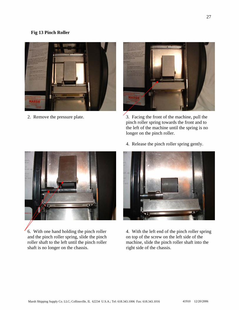
27
Fig 13 Pinch Roller
2. Remove the pressure plate.
3. Facing the front of the machine, pull the pinch roller spring towards the front and to the left of the machine until the spring is no longer on the pinch roller. 4. Release the pinch roller spring gently.
6. With one hand holding the pinch roller and the pinch roller spring, slide the pinch roller shaft to the left until the pinch roller shaft is no longer on the chassis.
Marsh Shipping Supply Co. LLC; Collinsville, IL 62234 U.S.A.; Tel: 618.3
4. With the left end of the pinch roller springon top of the screw on the left side of the machine, slide the pinch roller shaft into the right side of the chassis.
43.1006 Fax: 618.343.1016 41910 12/20/2006

Marsh Shipping Supply Co. LLC; Collinsville, IL 62234 U.S.A.; Tel: 618.343.1006 Fax: 618.343.1016
28
41910 12/20/2006
Removing the Weighted Brush Cover To remove the weighted brush cover, see Fig 14 and follow the steps below.
1. Turn the switch to OFF and unplug the machine. 2. Remove the right side cover (refer to Removing the Right Side
Cover [p. 20]). 3. Remove the water bottle. 4. Remove the cutter guard. 5. Remove the screws from the flapper shaft. 6. Slide the flapper shaft, weighted brush cover, tape weight, and
bushings from the front of the machine. 7. Remove the screw from the tape weight and remove the tape w
from the weighted brush cover. The weighted brush cover is now removed from the machine. At this point, a new weighted brush cover or tape weight may be installed.
Attaching the Weighted Brush Cover
eight
To attach the weighted brush cover, see Fig 14 and follow the steps below.
1. Position the tape weight into the new weighted brush cover and attach the screw to the weight.
2. Slide the flapper shaft into the weighted brush cover and then slide the bushings on each end of the shaft.
3. Position the weighted brush cover assembly in the chassis. 4. Attach the screws to the flapper shaft. 5. Attach the cutter guard. 6. Attach the water bottle. 7. Attach the right side cover (refer to Attaching the Right Side
Cover [p. 20]). The machine is now ready to continue normal operation.

Marsh Shipping Supply Co. LLC; Collinsville, IL 62234 U.S.A.; Tel: 618.343.1006 Fax: 618.343.1016
29
41910 12/20/2006
6. Slide the flapper shaft, weighted brush cover, tape weight, and bushings from the front of the machine.
5. Remove the screws from the flapper shaft.
Fig 14 Weighted Brush Cover

Marsh Shipping Supply Co. LLC; Collinsville, IL 62234 U.S.A.; Tel: 618.343.1006 Fax: 618.343.1016
30
41910 12/20/2006
To attach the tape channel plate, see Fig 15 and follow the steps below.
1. Place the tape channel plate on the dead roller so that the screw holes on the tape channel plate and the dead roller line up.
2. Attach the tape channel plate to the dead roller with two screws. 3. Push down on the tape channel plate until the holes in the chassis line
up with the holes in the tape channel plate. 4. Attach the tape channel plate to the chassis with two screws. 5. Attach the pinch roller spring stop. 6. Tighten the dead roller and coder bar screws. 7. Attach the weighted brush cover (refer to Attaching the Weighted
Brush Cover [p. 28]). 8. Attach the pinch roller (refer to Attaching the Pinch Roller [p. 26]). 9. Attach the right side cover (refer to Attaching the Right Side Cover
[p. 20]). The machine is now ready to continue normal operation.
Attaching the Tape Channel Plate
To remove the tape channel plate, see Fig 15 and follow the steps below.
1. Turn the switch to OFF and unplug the machine. 2. Remove the right side cover (refer to Removing the Right Side Cover
[p. 20]). 3. Remove the pinch roller (refer to Removing the Pinch Roller [p. 26]). 4. Remove the weighted brush cover (refer to Removing the Weighted
Brush Cover [p. 28]). 5. Loosen the dead roller and the coder bar screws. 6. Remove the pinch roller spring stop. 7. Remove the two screws attached to the tape channel plate. 8. Pull the tape channel plate up allowing the tape channel plate and the
dead roller to rotate so the screws underneath are accessible. 9. Remove the two screws connecting the tape channel plate and the dead
roller. The tape channel plate is now removed. At this point, a new tape channel plate may be installed.
Removing the Tape Channel Plate

31
Fig 15 Tape Channel Plate
8. Pull up on the tape channel plate so that the tape channel plate and the dead roller rotate so that the screws underneath are accessible.
5. Loosen the dead roller and the coder bar screws. 6. Remove the pinch roller spring stop.
9. Remove the two screws connecting the tape channelplate and the dead roller.Marsh Shipping Supply Co. LLC; Collinsville, IL 62234 U.S.A.; Tel: 618.343.1006 Fax: 618.343.1016 41910 12/20/2006

Marsh Shipping Supply Co. LLC; Collinsville, IL 62234 U.S.A.; Tel: 618.343.1006 Fax: 618.343.1016
32
41910 12/20/2006
To attach the tape basket/motor cover, see Fig 16 and follow the steps below.
1. Insert the tape basket/motor cover into the machine going straight into the center and through the top of the machine.
2. Attach the tape basket/motor cover with two screws. 3. Attach the tape channel plate (refer to Attaching the Tape Channel
Plate [p. 30]). 4. Attach the weighted brush cover (refer to Attaching the Weighted
Brush Cover [p. 28]). 5. Attach the pinch roller (refer to Attaching the Pinch Roller [p. 26]). 6. Attach the left side cover (refer to Attaching the Left Side Cover [p.
22]). 7. Attach the right side cover (refer to Attaching the Right Side Cover
[p. 20]). The machine is now ready to continue normal operation.
Removing the Tape Basket/Motor Cover To remove the tape basket/motor cover, see Fig 16 and follow the steps below.
1. Turn the switch to OFF and unplug the machine. 2. Remove the right side cover (refer to Removing the Right Side Cover
[p. 20]). 3. Remove the left side cover (refer to Removing the Left Side Cover [
22]). 4. Remove the pinch roller (refer to Removing the Pinch Roller [p. 26]). 5. Remove the weighted brush cover (refer to Removing the Weighted
Brush Cover [p. 28]). 6. Remove the tape channel plate (refer to Removing the Tape Channel
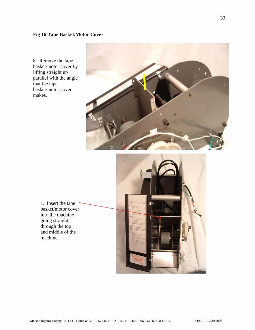
Plate [p. 30]). 7. Remove the two screws holding the tape basket/motor cover. 8. Remove the tape basket/motor cover by lifting straight up parallel with
the angle that the tape basket/motor cover makes. The large tape basket/motor cover is now removed. At this point, a new tape basket/motor cover may be installed.
Attaching the Tape Basket/Motor Cover
p.
33
Fig 16 Tape Basket/Motor Cover
8. Remove the tape basket/motor cover bylifting straight up parallel with the anglethat the tape basket/motor cover makes.
Marsh
1. Insert the tape basket/motor cover into the machine going straight through the top and middle of the machine.
Shipping Supply Co. LLC; Collinsville, IL 62234 U.S.A.; Tel: 618.343.1006 Fax: 618.343.1016 41910 12/20/2006

Marsh Shipping Supply Co. LLC; Collinsville, IL 62234 U.S.A.; Tel: 618.343.1006 Fax: 618.343.1016
34
41910 12/20/2006
To attach the water tank holder, see Fig 17 and follow the steps below.
1. With one hand pushing the chassis slightly apart, position the water tank holder.
2. Loosely attach the water tank holder with the seven screws. 3. With one hand pushing the chassis slightly apart, position the front
cover. 4. Attach the screws to the front cover. 5. Tighten the screws in the coder bar, dead roller, and water tank holder.
Attach the left side cover (refer to Attaching the Left Side Cover [p. 22]).
6. Attach the right side cover (refer to Attaching the Right Side Cover [p. 20]).
The machine is now ready to continue normal operation.
Attaching the Water Tank Holder
To remove the water tank holder, see Fig 17 and follow the steps below.
1. Turn the switch to OFF and unplug the machine. 2. Remove the right side cover (refer to Removing the Right Side Cover
[p. 20]). 3. Remove the left side cover (refer to Removing the Left Side Cover [
22]). 4. Loosen the screws in the coder bar and dead roller. 5. Remove the four screws from the front cover. 6. Remove the front cover. 7. Remove the seven screws from the water tank holder. 8. Remove the water tank holder.
The water tank holder is now removed. At this point, a new water tank holder may be installed.
p.
Removing the Water Tank Holder

35
Fig 17 Water Tank Holder
4. Loosen the screws in the coder bar anddead roller.Marsh Shipping Supply Co. LLC; Collinsville, IL 62234 U.S.A.; Tel: 618.343.1006 Fax: 618.343.1016 41910 12/20/2006
8. Remove the water tank holder.
6. Remove the front cover.

Marsh Shipping Supply Co. LLC; Collinsville, IL 62234 U.S.A.; Tel: 618.343.1006 Fax: 618.343.1016
36
41910 12/20/2006
1. Turn the switch to OFF and unplug the machine. the Right Side
3. side cover (refer to Removing the Left Side Cover [p.
4. he pinch roller (refer to Removing the Pinch Roller [p. 26]).
6. l plate (refer to Removing the Tape Channel
7. ter tank holder (refer to Removing the Water Tank
8. r arm springs from the screws they are resting upon.
he cutter arms are now removed from the machine. At this point new cutter
1. Insert the cutter arms into the slots in the movable cutter assembly.
. ing the Water Tank
6. annel plate (refer to Attaching the Tape Channel
7. hted brush cover (refer to Attaching the Weighted
8. efer to Attaching the Pinch Roller [p. 26]).
10. the right side cover (refer to Attaching the Right Side Cover
he machine is now ready to continue normal operation.
2. Insert the cutter arm shaft into the chassis and the cutter arms. 3. Attach the e-clips to the cutter arm shaft. 4. Attach the cutter arm springs to the screws5. Attach the water tank holder (refer to Attach
Holder [p. 34]). Attach the tape chPlate [p. 30]). Attach the weigBrush Cover [p. 28]). Attach the pinch roller (r
9. Attach the left side cover (refer to Attaching the Left Side Cover [p. 22]). Attach[p. 20]).
T
To replace the movable cutter assembly, see Fig 18 and follow the steps b
elow.
Attaching the Cutter Arms
Tarms may be installed.
2. Remove the right side cover (refer to Removing Cover [p. 20]). Remove the left 22]). Remove t
5. Remove the weighted brush cover (refer to Removing the Weighted Brush Cover [p. 28]). Remove the tape channePlate [p. 30]). Remove the waHolder [p. 34]). Remove the cutte
9. Remove the e-clips from the cutter arm shaft. 10. Remove the cutter arm shaft from the chassis. 11. Remove the cutter arms.
To replace the movable cutter assembly, see Fig 18 and follow the steps b
elow. Removing the Cutter Arms

Marsh Shipping Supply Co. LLC; Collinsville, IL 62234 U.S.A.; Tel: 618.343.1006 Fax: 618.343.1016
37
41910 12/20/2006
Fig 18 Cutter Arms
8. Remove the cutter arm springs from the screws they are resting on.
11. Remove the cutter arms.
10. Remove the cutter arm shaft from the chassis.

Marsh Shipping Supply Co. LLC; Collinsville, IL 62234 U.S.A.; Tel: 618.343.1006 Fax: 618.343.1016
38
41910 12/20/2006
elow.
1. Place the movable cutter into the precut slots in the chassis at an angle.
3. s (refer to Attaching the Cutter Arms [p. 36]).
5. annel plate (refer to Attaching the Tape Channel
6. hted brush cover (refer to Attaching the Weighted
7. efer to Attaching the Pinch Roller [p. 26]).
9. the right side cover (refer to Attaching the Right Side Cover
he machine is now ready to continue normal operation.
Removing the Movable Cutter Assembly To replace the movable cutter assembly, see Fig 19 and follow the steps below.
1. Turn the switch to OFF and unplug the machine. 2. Removing the Right Side Cover [p. 20]). 3. Remove the left side cover (refer to Removing the Left Side Cover [p.
22]). 4. Remove the pinch roller (refer to Removing the Pinch Roller [p. 26]). 5. Remove the weighted brush cover (refer to Removing the Weighted
Brush Cover [p. 28]). 6. Remove the tape channel plate (refer to Removing the Tape Channel
Plate [p. 30]). 7. Remove the water tank holder (refer to Removing the Water Tank
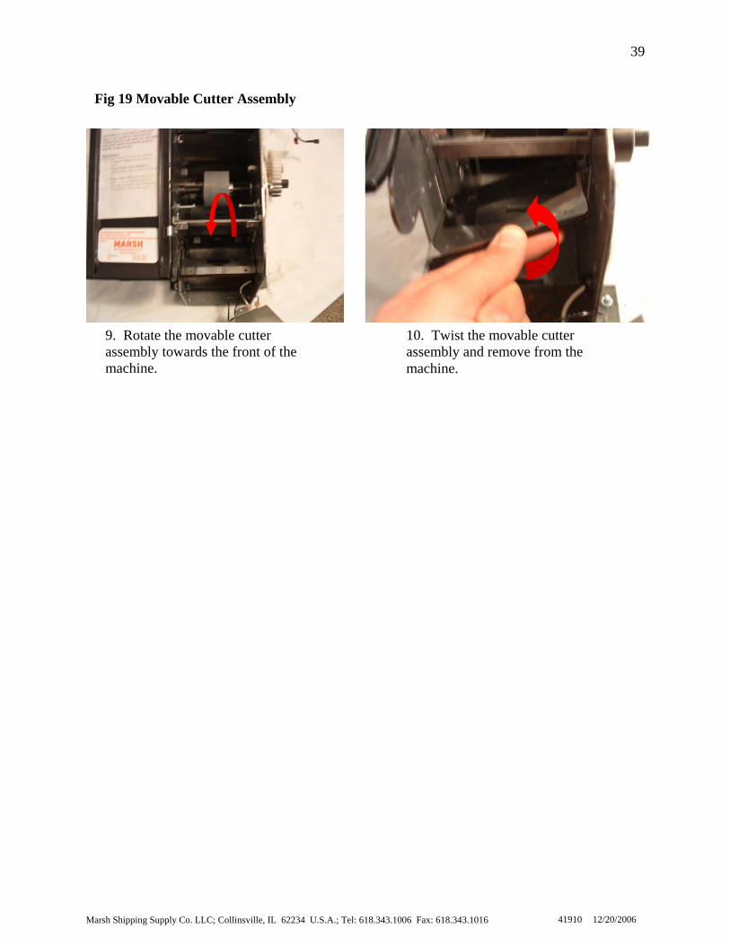
Holder [p. 34]). 8. Remove the cutter arms (refer to Removing the Cutter Arms [p. 36]). 9. Rotate the movable cutter assembly towards the front of the machine. 10. Twist the movable cutter assembly and remove from the machine.
The movable cutter assembly is now removed from the machine. At this point a new movable cutter assembly may be installed.
2. Untwist the movable cutter assembly and rotate the movable cutter assembly upwards. Attach the cutter arm
4. Attach the water tank holder (refer to Attaching the Water Tank Holder [p. 30]). Attach the tape chPlate [p. 28]). Attach the weigBrush Cover [p. 26]). Attach the pinch roller (r
8. Attach the left side cover (refer to Attaching the Left Side Cover [p. 22]). Attach[p. 20]).
T
To replace the movable cutter assembly, see Fig 19 and follow the steps b
Attaching the Movable Cutter Assembly
Ma
39
10. Twist the movable cutter assembly and remove from the machine.
Fig 19 Movable Cutter Assembly
9. Rotate the movable cutter assembly towards the front of themachine.
rsh Shipping Supply Co. LLC; Collinsville, IL 62234 U.S.A.; Tel: 618.343.1006 Fax: 618.343.1016 41910 12/20/2006
Marsh Shipping Supply Co. LLC; Collinsville, IL 62234 U.S.A.; Tel: 618.343.1006 Fax: 618.343.1016
40
41910 12/20/2006
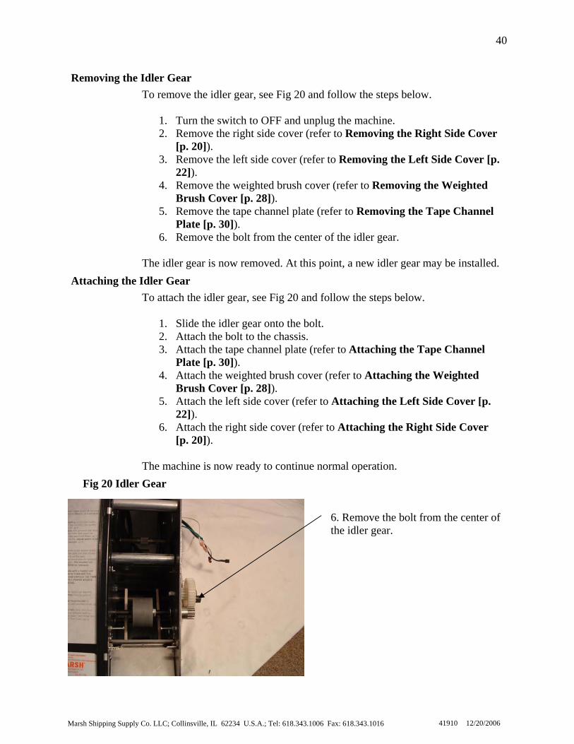
6. Remove the bolt from the center of the idler gear.
Removing the Idler Gear
To attach the idler gear, see Fig 20 and follow the steps below.
1. Slide the idler gear onto the bolt. 2. Attach the bolt to the chassis. 3. Attach the tape channel plate (refer to Attaching the Tape Channel
Plate [p. 30]). 4. Attach the weighted brush cover (refer to Attaching the Weighted
Brush Cover [p. 28]). 5. Attach the left side cover (refer to Attaching the Left Side Cover [p.
22]). 6. Attach the right side cover (refer to Attaching the Right Side Cover
[p. 20]). The machine is now ready to continue normal operation.
Attaching the Idler Gear
To remove the idler gear, see Fig 20 and follow the steps below.
1. Turn the switch to OFF and unplug the machine. 2. Remove the right side cover (refer to Removing the Right Side Cover
[p. 20]). 3. Remove the left side cover (refer to Removing the Left Side Cover [
22]). 4. Remove the weighted brush cover (refer to Removing the Weighted
Brush Cover [p. 28]). 5. Remove the tape channel plate (refer to Removing the Tape Channel
Plate [p. 30]). 6. Remove the bolt from the center of the idler gear.
The idler gear is now removed. At this point, a new idler gear may be installed.
p.
Fig 20 Idler Gear
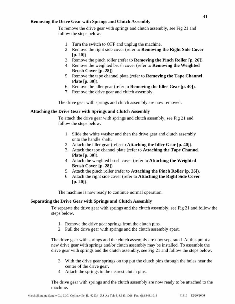
41Removing the Drive Gear with Springs and Clutch Assembly
To remove the drive gear with springs and clutch assembly, see Fig 21 and follow the steps below.
1. Turn the switch to OFF and unplug the machine. 2. Remove the right side cover (refer to Removing the Right Side Cover
[p. 20]). 3. Remove the pinch roller (refer to Removing the Pinch Roller [p. 26]). 4. Remove the weighted brush cover (refer to Removing the Weighted
Brush Cover [p. 28]). 5. Remove the tape channel plate (refer to Removing the Tape Channel
Plate [p. 30]). 6. Remove the idler gear (refer to Removing the Idler Gear [p. 40]). 7. Remove the drive gear and clutch assembly.
The drive gear with springs and clutch assembly are now removed.
Attaching the Drive Gear with Springs and Clutch Assembly To attach the drive gear with springs and clutch assembly, see Fig 21 and follow the steps below.
1. Slide the white washer and then the drive gear and clutch assembly onto the handle shaft.
2. Attach the idler gear (refer to Attaching the Idler Gear [p. 40]). 3. Attach the tape channel plate (refer to Attaching the Tape Channel
Plate [p. 30]). 4. Attach the weighted brush cover (refer to Attaching the Weighted
Brush Cover [p. 28]). 5. Attach the pinch roller (refer to Attaching the Pinch Roller [p. 26]). 6. Attach the right side cover (refer to Attaching the Right Side Cover
[p. 20]). The machine is now ready to continue normal operation.
Separating the Drive Gear with Springs and Clutch Assembly To separate the drive gear with springs and the clutch assembly, see Fig 21 and follow the steps below.
1. Remove the drive gear springs from the clutch pins. 2. Pull the drive gear with springs and the clutch assembly apart.
The drive gear with springs and the clutch assembly are now separated. At this point a new drive gear with springs and/or clutch assembly may be installed. To assemble the drive gear with springs and the clutch assembly, see Fig 21 and follow the steps below.
3. With the drive gear springs on top put the clutch pins through the holes near the center of the drive gear.
4. Attach the springs to the nearest clutch pins. The drive gear with springs and the clutch assembly are now ready to be attached to the machine.
Marsh Shipping Supply Co. LLC; Collinsville, IL 62234 U.S.A.; Tel: 618.343.1006 Fax: 618.343.1016 41910 12/20/2006

Marsh Shipping Supply Co. LLC; Collinsville, IL 62234 U.S.A.; Tel: 618.343.1006 Fax: 618.343.1016
42
41910 12/20/2006
2. Pull the drive gear with springs and the clutch assembly apart.
1. Remove the drive gear springs from the clutch pins.
7. Remove the drive gear and clutch assembly.
Fig 21 Drive Gear with Springs and Clutch Assembly

Marsh Shipping Supply Co. LLC; Collinsville, IL 62234 U.S.A.; Tel: 618.343.1006 Fax: 618.343.1016
43
41910 12/20/2006
Removing the Gearbox/Motor Mount
To remove the gearbox/motor mount, see Fig 22 and follow the steps below.
1. Turn the switch to OFF and unplug the machine. 2. Remove the right side cover (refer to Removing the Right Side Cover
[p. 20]). 3. Remove the pinch roller (refer to Removing the Pinch Roller [p. 26]). 4. Remove the weighted brush cover (refer to Removing the Weighted
Brush Cover [p. 28]). 5. Remove the tape channel plate (refer to Removing the Tape Channel
Plate [p. 30]). 6. Remove the idler gear (refer to Removing the Idler Gear [p. 40]). 7. Remove the drive gear and clutch assembly (refer to Removing the
Drive Gear with Springs and Clutch Assembly [p. 41]). 8. Remove the set screw from the feed wheel gear. 9. Remove the feed wheel gear. 10. Remove the bolts from the gearbox/motor mount. 11. Remove the gearbox/motor mount.
The gearbox/motor mount is now removed. At this point, a new gearbox/motor mount may be installed.
Attaching the Gearbox/Motor Mount
To attach the gearbox/motor mount, see Fig 22 and follow the steps below.
1. Align the gearbox/motor mount to the chassis using the pins in the gearbox/motor mount.
2. Attach the bolts to the gearbox/motor mount. 3. Slide the feed wheel gear onto the feed wheel shaft. 4. Attach the feed wheel gear to the feed wheel shaft using the set screw. 5. Attach the drive gear and clutch assembly (refer to Attaching the
Drive Gear with Springs and Clutch Assembly [p. 41]). 6. Attach the idler gear (refer to Attaching the Idler Gear [p. 40]). 7. Attach the tape channel plate (refer to Attaching the Tape Channel
Plate [p. 30]). 8. Attach the weighted brush cover (refer to Attaching the Weighted
Brush Cover [p. 28]). 9. Attach the pinch roller (refer to Attaching the Pinch Roller [p. 26]). 10. Attach the right side cover (refer to Attaching the Right Side Cover
[p. 20]). The machine is now ready to continue normal operation.

Marsh Shipping Supply Co. LLC; Collinsville, IL 62234 U.S.A.; Tel: 618.343.1006 Fax: 618.343.1016
44
41910 12/20/2006
10. Remove the bolts from the gearbox/motor mount.
8. Remove the set screw from the feed wheel gear. 9. Remove the feed wheel gear.
Fig 22 Gearbox/Motor Mount

Marsh Shipping Supply Co. LLC; Collinsville, IL 62234 U.S.A.; Tel: 618.343.1006 Fax: 618.343.1016
45
41910 12/20/2006
Fig 23 Moveable Cutter Blade
To replace the movable cutter blade, see Fig 23 and follow the steps below.
1. Turn the switch to OFF and unplug the machine. 2. Remove the cutter guard. 3. Release the tension from the blade by loosening the set screw. 4. With one hand pushing down on the handle, remove the two remaining
screws and lift the moveable cutter blade out of the machine.
NOTE: Place a pencil or screw driver or some other object beneath the cutter blade so that the cutter blade doesn’t fall into the machine.
5. With one hand holding the new moveable cutter blade, place the new movable cutter blade so that the two outside screw holes line up and screw the movable cutter blade into place.
6. Tighten the set screw so that there is a slight bend in the movable cutter blade.
7. Attach the cutter guard. The machine is now ready to continue normal operation.
Replacing the Movable Cutter Blade
4. With one hand pushing down on the handle, remove the two remaining screws and lift the moveable cutter blade out of the machine.

Marsh Shipping Supply Co. LLC; Collinsville, IL 62234 U.S.A.; Tel: 618.343.1006 Fax: 618.343.1016
46
41910 12/20/2006
Replacing the Thermostat Assembly
To replace the thermostat assembly, see Fig 26 and follow the steps below.
1. Turn the switch to OFF and unplug the machine. 2. Remove the right side cover (refer to Removing the Right Side Cover
[p. 20]). 3. Remove the left side cover (refer to Removing the Left Side Cover [
22]). 4. Remove the water tank holder (refer to Removing the Water Tank
Holder [p. 34]). 5. With one hand holding a screw driver inside the water tank holder,
remove the nuts holding on the thermostat. 6. Attach the new thermostat.
NOTE: The thermostat must have good surface contact.
7. Attach the water tank holder (refer to Attaching the Water Tank
Holder [p. 34]). 8. Attach the left side cover (refer to Attaching the Left Side Cover [p.
22]). 9. Attach the right side cover (refer to Attaching the Right Side Cover
[p. 20]). The machine is now ready to continue normal operation.
p.
To replace the brush, see Fig 25 and follow the steps below.
1. Turn OFF the machine. 2. Let the machine cool for at least 2 minutes. 3. Remove the water bottle. 4. Remove the water tank 5. Remove the brush from the water tank 6. Place the new brush in the tank so that the bristles of the brush lay
somewhat level with respect to the ground. 7. Place the water tank and brush into the water tank holder. 8. Place the water bottle onto the water bottle brackets with the post of the
water tank into the duckbill valve. The machine is now ready to continue normal operation.
Replacing the Brush

Marsh Shipping Supply Co. LLC; Collinsville, IL 62234 U.S.A.; Tel: 618.343.1006 Fax: 618.343.1016
47
41910 12/20/2006
Fig 25 Brush
6. Place the new brush in the tank so that the bristles of the brush lay somewhat level with respect to the ground. NOT PERPENDICULAR TO THE GROUND
5. With one hand holding a screw driver inside the water tank holder, remove the nuts holding on the thermostat.
Fig 26 Thermostat Assembly

Marsh Shipping Supply Co. LLC; Collinsville, IL 62234 U.S.A.; Tel: 618.343.1006 Fax: 618.343.1016
48
41910 12/20/2006
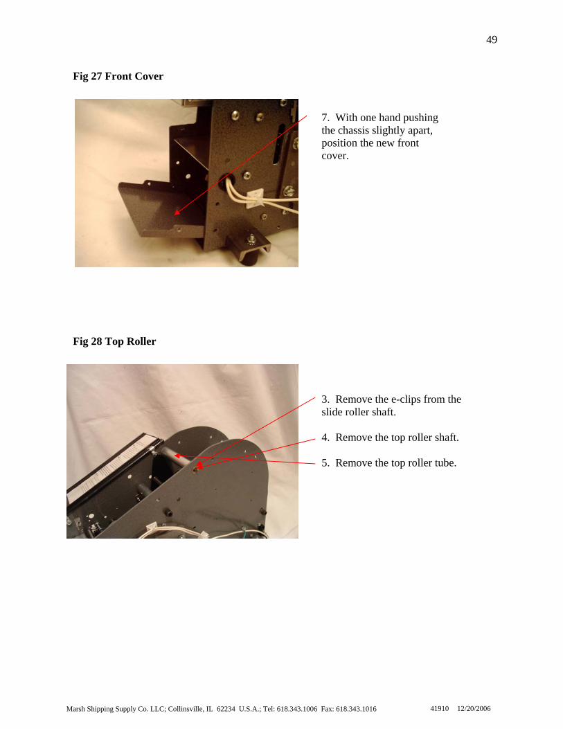
Replacing the Front Cover
To replace the front cover, see Fig 27 and follow the steps below.
1. Turn the switch to OFF and unplug the machine. 2. Remove the right side cover (refer to Removing the Right Side Cover
[p. 20]). 3. Remove the left side cover (refer to Removing the Left Side Cover [
22]). 4. Loosen the screws of the following parts: the coder bar, the dead roller,
the brush tank holder, and the weighted brush cover shaft. 5. Remove the four screws from the front cover. 6. Remove the front cover. 7. With one hand pushing the chassis slightly apart, position the new front
cover. 8. Attach the screws to the front cover. 9. Tighten the screws of the following parts: in the coder bar, the dead
roller, the brush tank holder, and the weighted brush cover shaft. 10. Attach the left side cover (refer to Attaching the Left Side Cover [p.
22]). 11. Attach the right side cover (refer to Attaching the Right Side Cover
[p. 20]). The machine is now ready to continue normal operation.
p.
To replace the top roller, see Fig 28 and follow the steps below.
1. Turn the switch to OFF and unplug the machine. 2. Remove the right side cover (refer to Removing the Right Side Cover
[p. 20]). 3. Remove the e-clips from the top roller shaft. 4. Remove the top roller shaft. 5. Remove the top roller tube. 6. Place the new top roller into the middle of the chassis and hold. 7. Insert the new top roller shaft into the chassis and into the top roller a
through the other side of the chassis. 8. Attach the e-clips to each side of the slide roller shaft. 9. Attach the right side cover (refer to Attaching the Right Side Cover
[p. 20]). The machine is now ready to continue normal operation.
nd
Replacing the Top Roller
Marsh Shipping Supply Co. LLC; Collinsville, IL 62234 U.S.A.; Tel: 618.343.1006 Fax: 618.343.1016
49
41910 12/20/2006
3. Remove the e-clips from the slide roller shaft. 4. Remove the top roller shaft. 5. Remove the top roller tube.
7. With one hand pushing the chassis slightly apart, position the new front cover.
Fig 27 Front Cover
Fig 28 Top Roller
Marsh Shipping Supply Co. LLC; Collinsville, IL 62234 U.S.A.; Tel: 618.343.1006 Fax: 618.343.1016
50
41910 12/20/2006
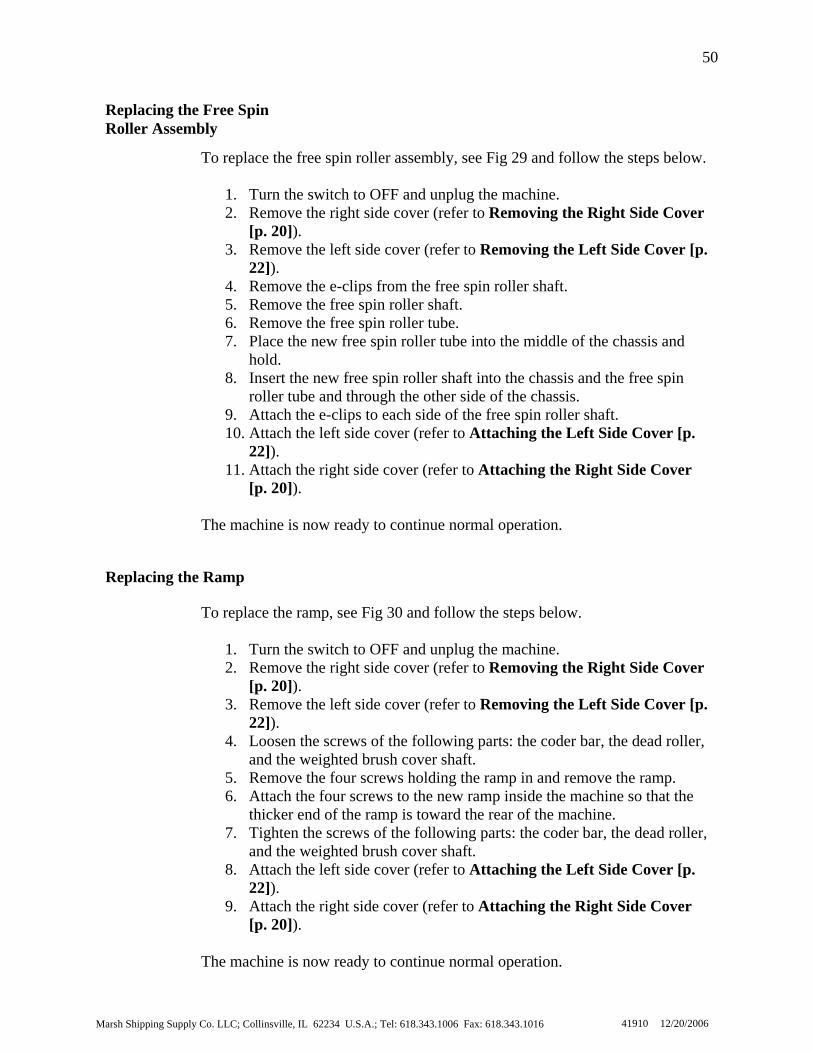
To replace the ramp, see Fig 30 and follow the steps below.
1. Turn the switch to OFF and unplug the machine. 2. Remove the right side cover (refer to Removing the Right Side Cover
[p. 20]). 3. Remove the left side cover (refer to Removing the Left Side Cover [
22]). 4. Loosen the screws of the following parts: the coder bar, the dead roller,
and the weighted brush cover shaft. 5. Remove the four screws holding the ramp in and remove the ramp. 6. Attach the four screws to the new ramp inside the machine so that the
thicker end of the ramp is toward the rear of the machine. 7. Tighten the screws of the following parts: the coder bar, the dead roller,
and the weighted brush cover shaft. 8. Attach the left side cover (refer to Attaching the Left Side Cover [p.
22]). 9. Attach the right side cover (refer to Attaching the Right Side Cover
[p. 20]). The machine is now ready to continue normal operation.
p.
Replacing the Ramp
To replace the free spin roller assembly, see Fig 29 and follow the steps below.
1. Turn the switch to OFF and unplug the machine. 2. Remove the right side cover (refer to Removing the Right Side Cover
[p. 20]). 3. Remove the left side cover (refer to Removing the Left Side Cover [
22]). 4. Remove the e-clips from the free spin roller shaft. 5. Remove the free spin roller shaft. 6. Remove the free spin roller tube. 7. Place the new free spin roller tube into the middle of the chassis and
hold. 8. Insert the new free spin roller shaft into the chassis and the free spin
roller tube and through the other side of the chassis. 9. Attach the e-clips to each side of the free spin roller shaft. 10. Attach the left side cover (refer to Attaching the Left Side Cover [p.
22]). 11. Attach the right side cover (refer to Attaching the Right Side Cover
[p. 20]). The machine is now ready to continue normal operation.
p.
Replacing the Free Spin Roller Assembly

Marsh Shipping Supply Co. LLC; Collinsville, IL 62234 U.S.A.; Tel: 61
51
4. Remove the e-clips from the free spin roller shaft. 5. Remove the free spin roller shaft.
Fig 29 Free Spin Roller Assembly
Fig 30 Ramp
4. Loosen the screws of the following parts: the coder bar, the dead roller, and the weighted brush cover shaft. 5. Remove the four screws holding the ramp in and remove the ramp.
6. Attach the four screws to the new ramp inside the machine so that the thickerend of the ramp is toward the rear of the machine.
8.343.1006 Fax: 618.343.1016 41910 12/20/2006

Marsh Shipping Supply Co. LLC; Collinsville, IL 62234 U.S.A.; Tel: 618.343.1006 Fax: 618.343.1016
52
41910 12/20/2006
To replace the fixed blade, see Fig 32 and follow the steps below.
1. Turn the switch to OFF and unplug the machine. 2. Remove the right side cover (refer to Removing the Right Side Cover
[p. 20]). 3. Push the fixed blade shoe toward the rear of the machine. 4. Use a magnet to pull fixed blade from the machine. 5. Insert the new fixed blade into the chassis. The blade should be resting
on both sides of the chassis.
CAUTION: Do not drop any components into the machine.
6. Release the fixed blade shoe. 7. Attach the right side cover (refer to Attaching the Right Side Cover
[p. 20]). The machine is now ready to continue normal operation.
Replacing the Fixed Blade
Replacing the Tape Guide Assembly
To replace the tape guide assembly, see Fig 31 and follow the steps below.
1. Turn the switch to OFF and unplug the machine. 2. Remove the right side cover (refer to Removing the Right Side Cover
[p. 20]). 3. Remove the left side cover (refer to Removing the Left Side Cover [
22]). 4. Remove the pressure plate. 5. Loosen the screws of the following parts: the coder bar, the dead roller,
the tape basket/motor cover, the tape channel plate, and the weighted brush cover shaft.
6. With the tape guides set towards the middle of the machine and one hand spreading the chassis apart, pull the turnbuckle to one side of the machine, twist the turnbuckle slightly and pull the assembly out the rear of the machine.
7. With the new tape guides set towards the middle of the machine and slightly twisted, and one hand spreading the chassis apart, put both ends of the turnbuckle into the chassis.
8. Tighten the screws of the following parts: the coder bar, the dead roller, the tape basket/motor cover, the tape channel plate, and the weighted brush cover shaft.
9. Attach the left side cover (refer to Attaching the Left Side Cover [p. 22]).
10. Attach the right side cover (refer to Attaching the Right Side Cover [p. 20]).
The machine is now ready to continue normal operation.
p.

Marsh Shipping Supply Co. LLC; Collinsville, IL 62234 U.S.A.; Tel: 618.343.1006 Fax: 618.343.1016
53
41910 12/20/2006
3. Push the fixed blade shoe toward the rear of the machine.
4. Use a magnet to pull fixed blade from the machine.
6. With the tape guides set towards the middle of the machine and one hand spreading the chassis apart, pull the turnbuckle to one side of the machine, twist the turnbuckle slightly and pull the assembly out the rear of the machine.
Fig 32 Fixed Blade
Fig 31 Tape Guide Assembly

Marsh Shipping Supply Co. LLC; Collinsville, IL 62234 U.S.A.; Tel: 618.343.1006 Fax: 618.343.1016
54
41910 12/20/2006
Replacing the Feed Wheel
To replace the feed wheel, see Fig 33 and follow the steps below.
1. Turn the switch to OFF and unplug the machine. 2. Remove the right side cover (refer to Removing the Right Side Cover
[p. 20]). 3. Remove the pinch roller (refer to Removing the Pinch Roller [p. 26]). 4. Remove the weighted brush cover (refer to Removing the Weighted
Brush Cover [p. 28]). 5. Remove the tape channel plate (refer to Removing the Tape Channel
Plate [p. 30]). 6. Remove the idler gear (refer to Removing the Idler Gear [p. 40]). 7. Remove the drive gear with springs and clutch assembly (refer to
Removing the Drive Gear with Springs and Clutch Assembly [p. 41]).
8. Remove the gearbox/motor mount (refer to Removing the Gearbox/Motor Mount [p. 43]).
9. Remove the feed wheel shaft and the feed wheel from the chassis at a downward angle.
10. Attach the e-clip and the washer to the new feed wheel shaft. 11. Insert the new feed wheel shaft and feed wheel into the chassis into the
bearing. 12. Attach the gearbox/motor mount (refer to Attaching the
Gearbox/Motor Mount [p. 43]). 13. Attach the drive gear and clutch assembly (refer to Attaching the
Drive Gear with Springs and Clutch Assembly [p. 41]). 14. Attach the idler gear (refer to Attaching the Idler Gear [p. 40]). 15. Attach the tape channel plate (refer to Attaching the Tape Channel
Plate [p. 30]). 16. Attach the weighted brush cover (refer to Attaching the Weighted
Brush Cover [p. 28]). 17. Attach the pinch roller (refer to Attaching the Pinch Roller [p. 26]). 18. Attach the right side cover (refer to Attaching the Right Side Cover
[p. 20]). The machine is now ready to continue normal operation.

Marsh Shipping Supply Co. LLC; Collinsville, IL 62234 U.S.A.; Tel: 618.343.1006 Fax: 618.343.1016
55
41910 12/20/2006
9. Remove the feed wheel shaft and the feed wheel from the chassis at a downward angle.
10. Attach the e-clip and the washer to the new feed wheel shaft
11. Insert the new feed wheel shaft and feed wheel into the chassis into the bearing.
Fig 33 Feed Wheel
Marsh Shipping Supply Co. LLC; Collinsville, IL 62234 U.S.A.; Tel: 618.343.1006 Fax: 618.343.1016
56
41910 12/20/2006
eturn
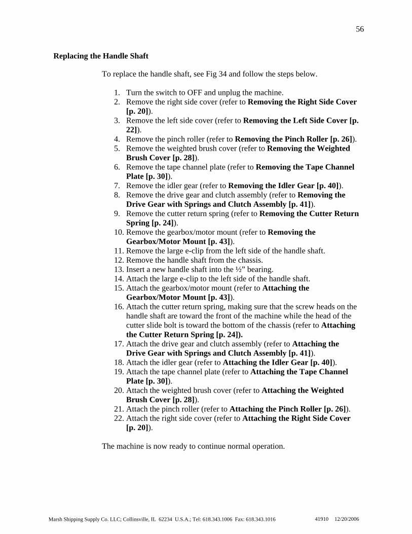
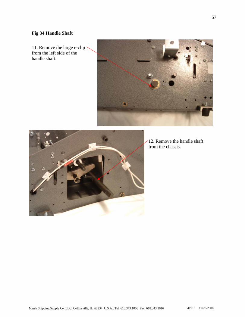
To replace the handle shaft, see Fig 34 and follow the steps below.
1. Turn the switch to OFF and unplug the machine. 2. Remove the right side cover (refer to Removing the Right Side Cover
[p. 20]). 3. Remove the left side cover (refer to Removing the Left Side Cover [
22]). 4. Remove the pinch roller (refer to Removing the Pinch Roller [p. 26]). 5. Remove the weighted brush cover (refer to Removing the Weighted
Brush Cover [p. 28]). 6. Remove the tape channel plate (refer to Removing the Tape Channel
Plate [p. 30]). 7. Remove the idler gear (refer to Removing the Idler Gear [p. 40]). 8. Remove the drive gear and clutch assembly (refer to Removing the
Drive Gear with Springs and Clutch Assembly [p. 41]). 9. Remove the cutter return spring (refer to Removing the Cutter R
Spring [p. 24]). 10. Remove the gearbox/motor mount (refer to Removing the
Gearbox/Motor Mount [p. 43]). 11. Remove the large e-clip from the left side of the handle shaft. 12. Remove the handle shaft from the chassis. 13. Insert a new handle shaft into the ½” bearing. 14. Attach the large e-clip to the left side of the handle shaft. 15. Attach the gearbox/motor mount (refer to Attaching the
Gearbox/Motor Mount [p. 43]). 16. Attach the cutter return spring, making sure that the screw heads on the
handle shaft are toward the front of the machine while the head of the cutter slide bolt is toward the bottom of the chassis (refer to Attaching the Cutter Return Spring [p. 24]).
17. Attach the drive gear and clutch assembly (refer to Attaching the Drive Gear with Springs and Clutch Assembly [p. 41]).
18. Attach the idler gear (refer to Attaching the Idler Gear [p. 40]). 19. Attach the tape channel plate (refer to Attaching the Tape Channel
Plate [p. 30]). 20. Attach the weighted brush cover (refer to Attaching the Weighted
Brush Cover [p. 28]). 21. Attach the pinch roller (refer to Attaching the Pinch Roller [p. 26]). 22. Attach the right side cover (refer to Attaching the Right Side Cover
[p. 20]). The machine is now ready to continue normal operation.
p.
Replacing the Handle Shaft
Marsh Shipping Supply Co. LLC; Collinsville, IL 62234 U.S.A.; Tel: 618.343.1006 Fax: 618.343.1016
57
41910 12/20/2006
12. Remove the handle shaft from the chassis.
11. Remove the large e-clip from the left side of the handle shaft.
Fig 34 Handle Shaft
58
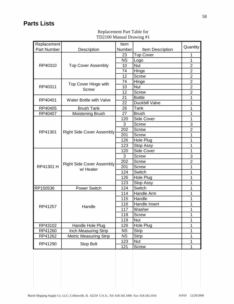
Parts Lists
Replacement Part Number Description
Item Number Item Description Quantity
23 Top Cover 1NS Logo 110 Nut 274 Hinge 212 Screw 274 Hinge 210 Nut 212 Screw 221 Bottle 122 Duckbill Valve 1
RP40405 Brush Tank 26 Tank 1RP40407 Moistening Brush 27 Brush 1
120 Side Cover 13 Screw 3
202 Screw 2201 Screw 1126 Hole Plug 1123 Stop Assy 1120 Side Cover 13 Screw 3
202 Screw 2201 Screw 1124 Switch 1126 Hole Plug 1123 Stop Assy 1
RP150536 Power Switch 124 Switch 1114 Handle Arm 1115 Handle 1116 Handle Insert 1117 Washer 1118 Screw 1119 Nut 1
RP43102 Handle Hole Plug 126 Hole Plug 1RP41260 Inch Measuring Strip NS Strip 1RP41262 Metric Measuring Strip NS Strip 1
123 Nut 1121 Screw 1
RP41290 Stop Bolt
Top Cover AssemblyRP40310
RP40311 Top Cover Hinge with Screw
Water Bottle with ValveRP40401
Right Side Cover Assembly
Handle
RP41301
RP41257
RP41301 H Right Side Cover Assembly w/ Heater
Replacement Part Table for TD2100 Manual Drawing #1
Marsh Shipping Supply Co. LLC; Collinsville, IL 62234 U.S.A.; Tel: 618.343.1006 Fax: 618.343.1016 41910 12/20/2006
Marsh Shipping Supply Co. LLC; Collinsville, IL 62234 U.S.A.; Tel: 618.343.1006 Fax: 618.343.1016
59
41910 12/20/2006
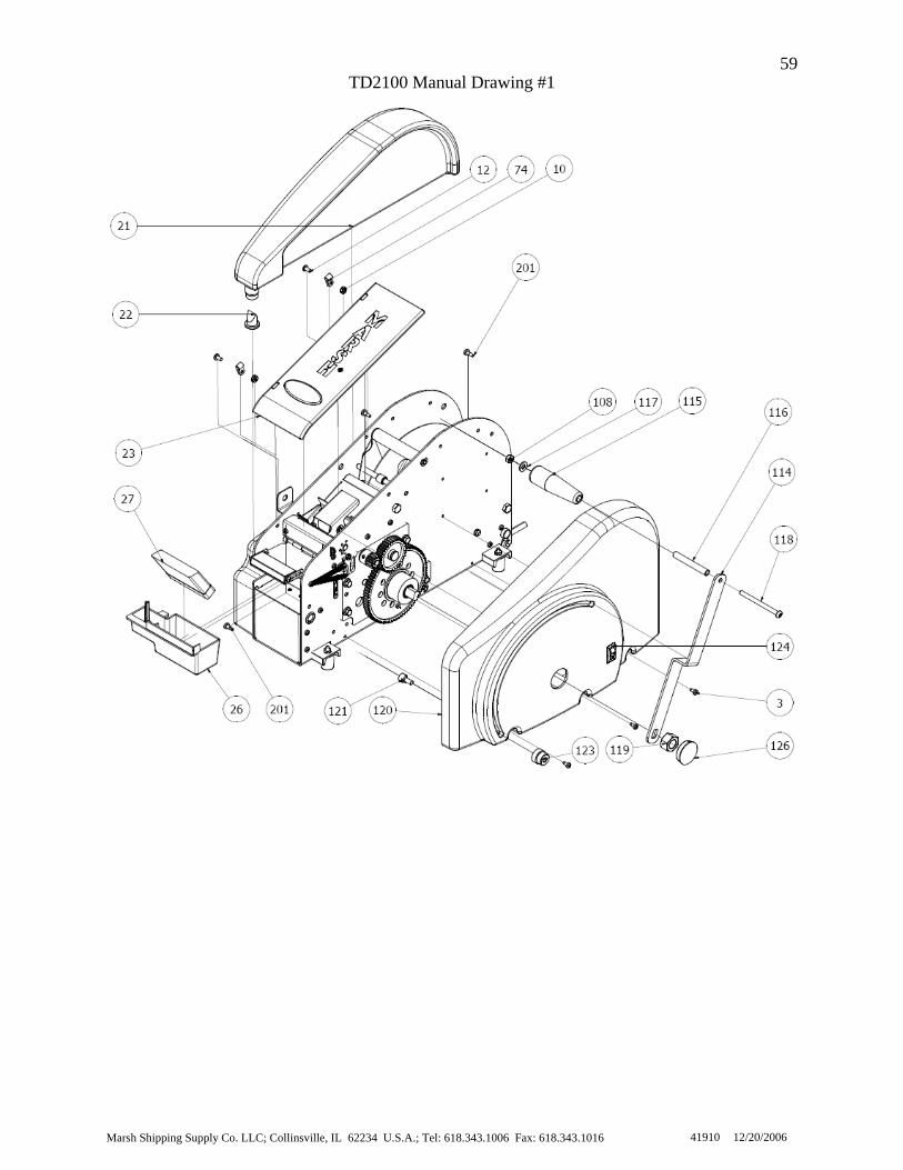
TD2100 Manual Drawing #1
Marsh Shipping Supply Co. LLC; Collinsville, IL 62234 U.S.A.; Tel: 618.343.1006 Fax: 618.343.1016
60
41910 12/20/2006
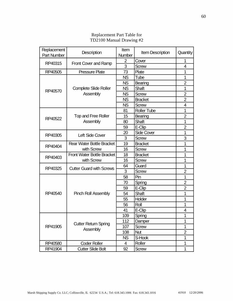
Replacement Part Table for TD2100 Manual Drawing #2
Replacement Part Number Description Item
Number Item Description Quantity
2 Cover 13 Screw 4
RP40505 Pressure Plate 73 Plate 1NS Tube 1NS Bearing 2NS Shaft 1NS Screw 2NS Bracket 2NS Screw 481 Roller Tube 115 Bearing 280 Shaft 159 E-Clip 220 Side Cover 13 Screw 319 Bracket 116 Screw 118 Bracket 116 Screw 164 Guard 13 Screw 258 Pin 170 Spring 259 E-Clip 254 Shaft 155 Holder 156 Roll 141 E-Clip 4109 Spring 1112 Damper 1107 Screw 1108 Nut 2NS S-Hook 1
RP40580 Coder Roller 4 Roller 1RP41904 Cutter Slide Bolt 92 Screw 1
RP40403 Front Water Bottle Bracket with Screw
Front Cover and RampRP40315
RP40305 Left Side Cover
RP40404 Rear Water Bottle Bracket with Screw
Complete Slide Roller AssemblyRP40570
RP40522 Top and Free Roller Assembly
RP41905 Cutter Return Spring Assembly
RP40325 Cutter Guard with Screws
Pinch Roll AssemblyRP40540

61
TD2100 Manual Drawing #2
Marsh Shipping Supply Co. LLC; Collinsville, IL 62234 U.S.A.; Tel: 618.343.1006 Fax: 618.343.1016 41910 12/20/2006

62
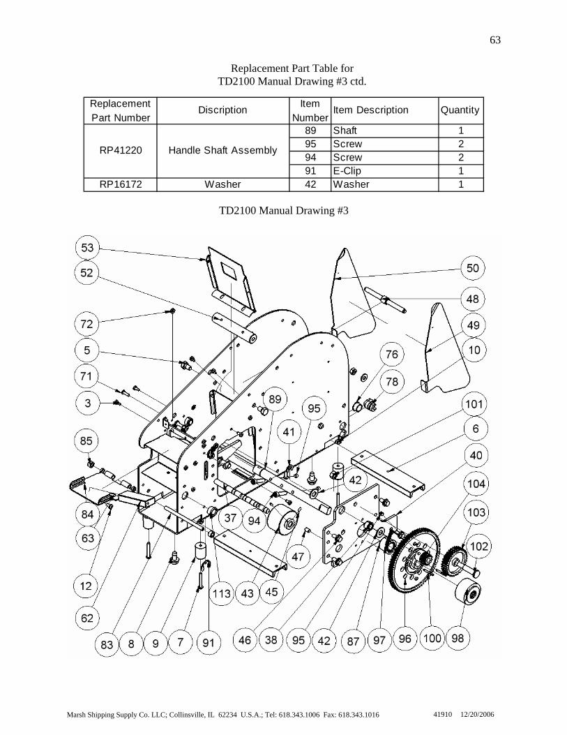
Replacement Part Table for TD2100 Manual Drawing #3
Replacement
Part NumberDescription Item
NumberItem Description Quantity
6 Bar 18 Screw 19 Rubber Foot 17 Screw 110 Nut 153 Plate 13 Screw 248 Turnbuckle 149 Guide RHS 150 Guide LHS 1
RP42956 900 Strain Relief 78 Power Cord Relief 1RP42957 Dome Plug 76 Plug 1RP42958 Split Bushing 113 Split Bushing 1
43 Wheel 145 Screw 2NS Tube 1NS Bearing 2NS Shaft 1NS Screw 2NS Bracket 2NS Screw 440 Gearbox/Motor Frame 147 Pin 296 Drive Gear 197 Spring 298 Clutch 1
100 Pin 284 Weighted Tank Cover 13 Screw 285 Brass Bushing 283 Rod 162 Weight 112 Screw 163 Pin 1
RP40231 3/8 Bearing 38 Bearing 1RP41221 1/2 Bearing 87 Bearing 1
52 Roll 15 Screw 1
RP40230 Feed Wheel Shaft 37 Shaft 1
RP40560 Dead Roller
RP5063X Clutch Roller Assembly
RP40516Brush Tank Cover With Rod
and Bushings
RP40517 Tape Weight With Screw
RP41101 Gearbox/Motor Mount Frame with Pins
RP5065X Drive Gear with Springs
RP40545 Urethane Feed Wheel
RP40570Complete Slide Roller
Assembly
RP40110 Foot Channel
RP40115 Rubber Foot
Tape Channel PlateRP40515
Tape Guide AssemblyRP40550
Marsh Shipping Supply Co. LLC; Collinsville, IL 62234 U.S.A.; Tel: 618.343.1006 Fax: 618.343.1016 41910 12/20/2006
63
Replacement Part Table for TD2100 Manual Drawing #3 ctd.
Replacement Part Number
Discription Item Number
Item Description Quantity
89 Shaft 195 Screw 294 Screw 291 E-Clip 1
RP16172 Washer 42 Washer 1
RP41220 Handle Shaft Assembly
TD2100 Manual Drawing #3
Marsh Shipping Supply Co. LLC; Collinsville, IL 62234 U.S.A.; Tel: 618.343.1006 Fax: 618.343.1016 41910 12/20/2006

64
Replacement Part Table for
TD2100 Manual Drawing #4
Replacement Part Number
Description Item Number
Item Description Quantity
51 Steel Plate 13 Screw 293 Arm 2
106 Spring 241 E-Clip 637 Shaft 1
105 Screw 272 Nut 429 Cutter Blade Holder 130 Cutter Blade-Movable 134 Fixed Blade 136 Springs 435 Fixed Blade Shoe 131 Set Screw 169 Screw 233 Screw 232 Bushing 228 Cutter Guide 230 Cutter Blade-Movable 169 Screw 231 Set Screw 134 Fixed Blade 136 Spring 235 Fixed Blade Shoe 2NS Shoe Lock 225 Water Tank Holder 165 Thermostat 110V 166 Screw 267 Nut 268 Heater 110V 13 Screw 7
NS WireNS Wire Connections65 Thermostat 110V 166 Screw 267 Nut 2NS WireNS Wire Connections
RP40231 3/8 Bearing 38 Bearing 1RP41221 1/2 Bearing 87 Bearing 1
Cutter Blade-MovableRP40710
RP40715 Cutter Blade-Fixed
Cutter Replacement KitRP40701
RP40320 Tape Basket/Motor Cover
Cutter Actuating Arm AssemblyRP5072
Thermostat Assembly 110V
RP43977
Heater/Thermostat Assembly 110VRP42978
Marsh Shipping Supply Co. LLC; Collinsville, IL 62234 U.S.A.; Tel: 618.343.1006 Fax: 618.343.1016 41910 12/20/2006

65
Replacement Part Table for TD2100 Manual Drawing #4 ctd.
Replacement Part Number Discription Item
Number Item Description Quantity
25 Water Tank Holder 165 Thermostat 220V 166 Screw 267 Nut 268 Heater 220V 13 Screw 7
NS WireNS Wire Connections60 Clip 13 Screw 272 Nut 1105 Screw 125 Water Tank Holder 13 Screw 7
Water Tank HolderRP40352
RP41290 Stop Bolt and Nut
RP42810Heater/Thermostat Assembly 220V
RP40236 Cutter Guard Clip
TD2100 Manual Drawing #4
Marsh Shipping Supply Co. LLC; Collinsville, IL 62234 U.S.A.; Tel: 618.343.1006 Fax: 618.343.1016 41910 12/20/2006

Marsh Shipping Supply Co. LLC; Collinsville, IL 62234 U.S.A.; Tel: 618.343.1006 Fax: 618.343.1016
66
41910 12/20/2006
To attach the weighted brush cover, see Fig 35 and follow the steps below.
1. Position the tape weight into the new weighted brush cover and screw in the screw.
2. Slide one end of the flapper rod into to the chassis. 3. Place a bushing, then the weighted brush cover, then another bushing
on the flapper rod and slide the rod through the other side of the chassis.
4. Attach the e-clips to the flapper rod. 5. Attach the cutter guard. 6. Attach the water bottle.
The machine is now ready to continue normal operations
Removing the Weighted Brush Cover To remove the weighted brush cover, see Fig 35 and follow the steps below.
1. Remove the water bottle. 2. Remove the cutter guard. 3. Remove the e-clips from the flapper rod. 4. Slide the flapper rod from the machine 5. Remove the screw from the tape weight and remove the tape weight
from the weighted brush cover. The weighted brush cover is now removed from the machine. At this point a new weighted brush cover or tape weight may be installed.
Attaching the Weighted Brush Cover
Addendum

Marsh Shipping Supply Co. LLC; Collinsville, IL 62234 U.S.A.; Tel: 618.343.1006 Fax: 61
67
Fig 35 Weighted Brush Cover
2. Remove the cutter guard. 3. Remove the e-clips from theflapper rod.
4. Slide the flapper rod from themachine8.343.1016 41910 12/20/2006
Marsh Shipping Supply Co. LLC; Collinsville, IL 62234 U.S.A.; Tel: 618.343.1006 Fax: 618.343.1016
68
41910 12/20/2006
To replace the slide roller, see Fig 36 and follow the steps below.
1. Turn the switch to OFF and unplug the machine. 2. Remove the right side cover (refer to Removing the Right Side Cover
[p. 20]). 3. Remove the four screws holding the sliding roller plates. 4. Remove the slide roller assembly. 5. Place the new slide roller assembly into the middle of the chassis and
hold. 6. Attach the four screws to both of the sliding roller plates. 7. Attach the right side cover (refer to Attaching the Right Side Cover
[p. 20]). The machine is now ready to continue normal operation.
Replacing the Slide Roller
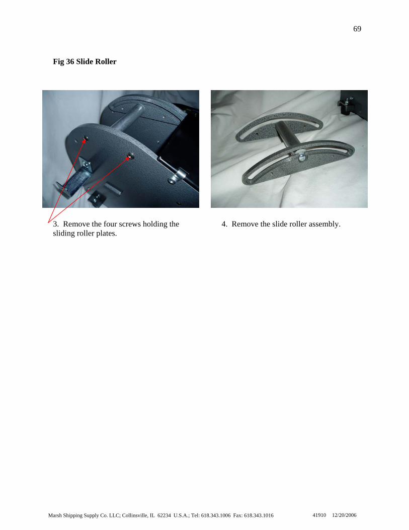
69
Fig 36 Slide Roller
4. Remove the slide roller assembly.
3. Remove the four screws holding thesliding roller plates.
Marsh Shipping Supply Co. LLC; Collinsville, IL 62234 U.S.A.; Tel: 618.343.1006 Fax: 618.343.1016 41910 12/20/2006