martin coupling brochure transmission/6... · c-3 couplings couplings whateveryourneedfor...
TRANSCRIPT

C-1
COUP
LING
S
IndexSECTIONC
COUPLINGS
PRODUCT PAGE
INDEX . . . . . . . . . . . . . . . . . . . . . . . . . . . . . . . . . . . . . . . . . . . . . . . . . . . . . . . . . . . . . . . . . . . . . . . . . . . . . . . . . . . .C-1
COUPLING COMPARISON . . . . . . . . . . . . . . . . . . . . . . . . . . . . . . . . . . . . . . . . . . . . . . . . . . . . . . . . . . . . . . . . . . .C-2
QUADRA-FLEX® . . . . . . . . . . . . . . . . . . . . . . . . . . . . . . . . . . . . . . . . . . . . . . . . . . . . . . . . . . . . . . . . . . . .C-4 — C-24
Sleeve Selection . . . . . . . . . . . . . . . . . . . . . . . . . . . . . . . . . . . . . . . . . . . . . . . . . . . . . . . . . . . . . . .C-7 — C-8
Selection Procedure . . . . . . . . . . . . . . . . . . . . . . . . . . . . . . . . . . . . . . . . . . . . . . . . . . . . . . . . . . . . . . . . . .C-9
Sleeves . . . . . . . . . . . . . . . . . . . . . . . . . . . . . . . . . . . . . . . . . . . . . . . . . . . . . . . . . . . . . . . . . . . . . . . . . . .C-14
Flanges . . . . . . . . . . . . . . . . . . . . . . . . . . . . . . . . . . . . . . . . . . . . . . . . . . . . . . . . . . . . . . . . . . . .C-15 — C-19
Keyseat Dimensions . . . . . . . . . . . . . . . . . . . . . . . . . . . . . . . . . . . . . . . . . . . . . . . . . . . . . . . . . . . . . . . . .C-18
Spacer Flanges . . . . . . . . . . . . . . . . . . . . . . . . . . . . . . . . . . . . . . . . . . . . . . . . . . . . . . . . . . . . . .C-20 — C-23
Installation . . . . . . . . . . . . . . . . . . . . . . . . . . . . . . . . . . . . . . . . . . . . . . . . . . . . . . . . . . . . . . . . . . . . . . . . .C-24
CHAIN COUPLING . . . . . . . . . . . . . . . . . . . . . . . . . . . . . . . . . . . . . . . . . . . . . . . . . . . . . . . . . . . . . . . . . .C-25 — C-27
Bored-To-Size . . . . . . . . . . . . . . . . . . . . . . . . . . . . . . . . . . . . . . . . . . . . . . . . . . . . . . . . . . . . . . . . . . . . . .C-26
QD . . . . . . . . . . . . . . . . . . . . . . . . . . . . . . . . . . . . . . . . . . . . . . . . . . . . . . . . . . . . . . . . . . . . . . . . . . . . . . .C-26
Taper Bushed . . . . . . . . . . . . . . . . . . . . . . . . . . . . . . . . . . . . . . . . . . . . . . . . . . . . . . . . . . . . . . . . . . . . . .C-26
Coupling Selection . . . . . . . . . . . . . . . . . . . . . . . . . . . . . . . . . . . . . . . . . . . . . . . . . . . . . . . . . . . . . . . . . .C-27
Plain Bore . . . . . . . . . . . . . . . . . . . . . . . . . . . . . . . . . . . . . . . . . . . . . . . . . . . . . . . . . . . . . . . . . . . . . . . . .C-27
Covers . . . . . . . . . . . . . . . . . . . . . . . . . . . . . . . . . . . . . . . . . . . . . . . . . . . . . . . . . . . . . . . . . . . . . . . . . . . .C-27
JAW COUPLING . . . . . . . . . . . . . . . . . . . . . . . . . . . . . . . . . . . . . . . . . . . . . . . . . . . . . . . . . . . . . . . . . . . .C-28 — C-30
Horsepower Ratings . . . . . . . . . . . . . . . . . . . . . . . . . . . . . . . . . . . . . . . . . . . . . . . . . . . . . . . . . . . . . . . . .C-29
ML & MS Hubs . . . . . . . . . . . . . . . . . . . . . . . . . . . . . . . . . . . . . . . . . . . . . . . . . . . . . . . . . . . . . . . . . . . . .C-30
ML & MS Spiders . . . . . . . . . . . . . . . . . . . . . . . . . . . . . . . . . . . . . . . . . . . . . . . . . . . . . . . . . . . . . . . . . . .C-30
Martin-FLEX® . . . . . . . . . . . . . . . . . . . . . . . . . . . . . . . . . . . . . . . . . . . . . . . . . . . . . . . . . . . . . . . . . . . . .C-31 — C-32
Stock Sizes . . . . . . . . . . . . . . . . . . . . . . . . . . . . . . . . . . . . . . . . . . . . . . . . . . . . . . . . . . . . . . . . . . . . . . .C-31
Engineering . . . . . . . . . . . . . . . . . . . . . . . . . . . . . . . . . . . . . . . . . . . . . . . . . . . . . . . . . . . . . . . . . . . . . . . .C-32
C-2
COUPLINGS
CouplingComparison
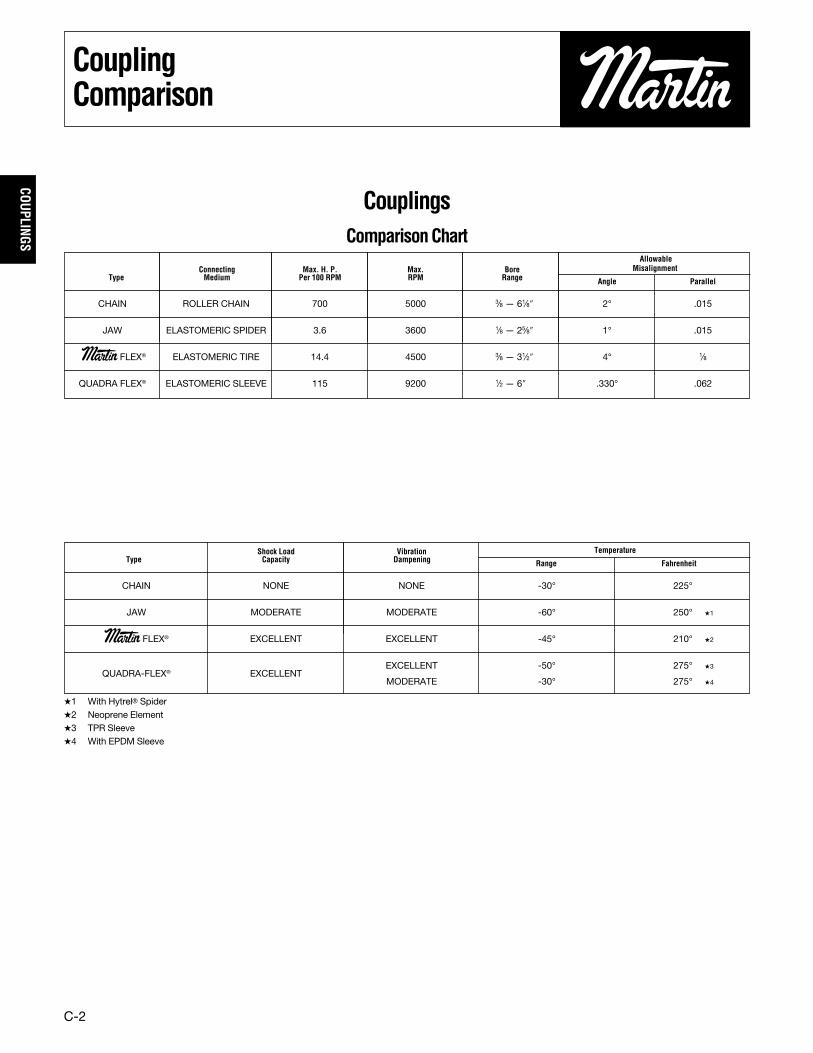
CouplingsComparisonChart
Shock Load Vibration TemperatureType Capacity Dampening Range Fahrenheit
CHAIN NONE NONE -30° 225°
JAW MODERATE MODERATE -60° 250° �1
Martin FLEX® EXCELLENT EXCELLENT -45° 210° �2
QUADRA-FLEX® EXCELLENTEXCELLENT -50° 275° �3
MODERATE -30° 275° �4
�1 With Hytrel® Spider�2 Neoprene Element�3 TPR Sleeve�4 With EPDM Sleeve
AllowableConnecting Max. H. P. Max. Bore Misalignment
Type Medium Per 100 RPM RPM Range Angle Parallel
CHAIN ROLLER CHAIN 700 5000 3⁄8 — 61⁄8″ 2° .015
JAW ELASTOMERIC SPIDER 3.6 3600 1⁄8 — 25⁄8″ 1° .015
Martin FLEX® ELASTOMERIC TIRE 14.4 4500 3⁄8 — 31⁄2″ 4° 1⁄8
QUADRA FLEX® ELASTOMERIC SLEEVE 115 9200 1⁄2 — 6″ .330° .062
C-3
COUP
LING
S
Couplings
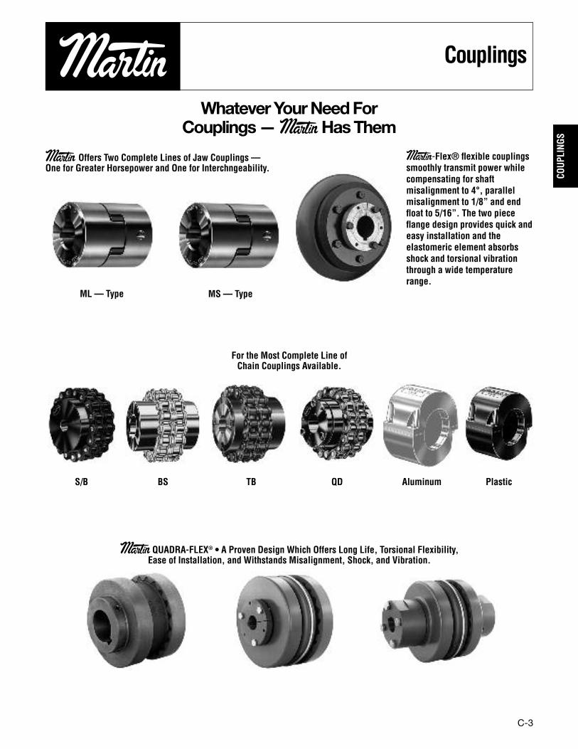
WhateverYourNeedForCouplings—MartinHasThem
Martin Offers Two Complete Lines of Jaw Couplings —One for Greater Horsepower and One for Interchngeability.
Martin-Flex® flexible couplingssmoothly transmit power whilecompensating for shaftmisalignment to 4°, parallelmisalignment to 1/8” and endfloat to 5/16”. The two pieceflange design provides quick andeasy installation and theelastomeric element absorbsshock and torsional vibrationthrough a wide temperaturerange.
For the Most Complete Line ofChain Couplings Available.
Martin QUADRA-FLEX® • A Proven Design Which Offers Long Life, Torsional Flexibility,Ease of Installation, and Withstands Misalignment, Shock, and Vibration.
ML — Type MS— Type
S/B BS TB QD Aluminum Plastic
C-4
COUPLINGS
QUADRA-FLEX®4-WayFlexing
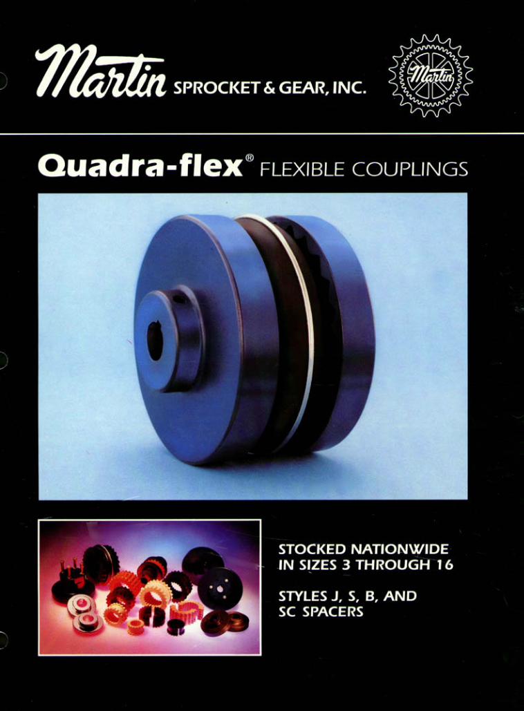
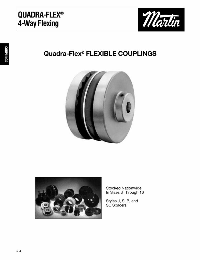
Quadra-Flex® FLEXIBLE COUPLINGS
Stocked NationwideIn Sizes 3 Through 16
Styles J, S, B, andSC Spacers
C-5
COUP
LING
S
QUADRA-FLEX®4-WayFlexing
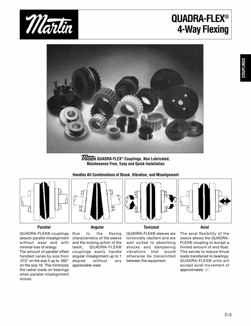
Martin QUADRA-FLEX® Couplings, Non Lubricated,Maintenance Free, Easy and Quick Installation
Handles All Combinations of Shock, Vibration, and Misalignment
QUADRA-FLEX® couplingsabsorb parallel misalignmentwithout wear and withminimal loss of energy.The amount of parallel offsethandled varies by size from.015″ on the size 5 up to .062″on the size 16. This minimizesthe radial loads on bearingswhen parallel misalignmentoccurs.
The axial flexibil ity of thesleeve allows the QUADRA-FLEX® coupling to accept alimited amount of end float.This serves to reduce thrustloads transferred to bearings.QUADRA-FLEX® units willaccept axial movement ofapproximately 1/8″.
Due to the flexingcharacteristics of the sleeveand the locking action of theteeth, QUADRA-FLEX®couplings easily handleangular misalignment up to 1degree without anyappreciable wear.
QUADRA-FLEX® sleeves aretorsionally resilient and arewell suited to absorbingshocks and dampeningvibrations that wouldotherwise be transmittedbetween the equipment.
Parallel Angular Torsional Axial
C-6
COUPLINGS
Styles
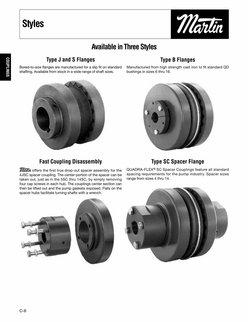
Available inThreeStyles
Fast Coupling Disassembly Type SC Spacer FlangeMartin offers the first true drop-out spacer assembly for the4JSC spacer coupling. The center portion of the spacer can betaken out, just as in the 5SC thru 14SC, by simply removingfour cap screws in each hub. The couplings center section canthen be lifted out and the pump gaskets exposed. Flats on thespacer hubs facilitate turning shafts with a wrench.
QUADRA-FLEX® SC Spacer Couplings feature all standardspacing requirements for the pump industry. Spacer sizesrange from sizes 4 thru 14.
Type J and S Flanges Type B FlangesBored-to-size flanges are manufactured for a slip fit on standardshafting. Available from stock in a wide range of shaft sizes.
Manufactured from high strength cast iron to fit standard QDbushings in sizes 6 thru 16.

C-7
COUP
LING
S
SleeveSelection
QUADRA-FLEX®Nomenclature
J� SINTERED STEEL, BORED-TO-SIZES CAST IRON, BORED-TO-SIZEB CAST IRON, QD BUSHEDSC SPACER COUPLING FLANGES
H REGULAR LENGTHHS SHORT LENGTH
JEM TPR – 1-PIECE SOLID, THERMOPLASTICJEMS TPR – 1-PIECE SPLIT, THERMOPLASTICEM TPR – 2-PIECE W/RETAINING RINGE EPDM – 2-PIECE W/RETAINING RINGN NEOPRENE – 2-PIECE W/RETAINING RINGH HYTREL – 1-PIECE SOLIDHS HYTREL – 2-PIECE
Type Description
Type Description
Type Description
QUADRA-FLEX® couplings come in a variety of styles anddesigns to meet specific customer needs. These includeflanges and sleeves of various types and materials. The totalproduct line includes 13 sizes varying in torque ratings up to72,000 in-lbs.
When ordering QUADRA-FLEX® couplings, the following basicprocedure should help expedite order processing. For couplingflanges, give the basic coupling size, then the letter for the typeflange followed by the bore size required. For coupling sleeves,give the coupling size followed by the letter(s) designating thetype and material required. (See above)
The following are various examples for reference:
Example: Type J Flange
Size Flange Bore5J x 3/4″ 5 J 3⁄4″7S x 30mm 7 S 30mm
(Note: Bored-to-size flanges are furnished with standardkeyway and 2 setscrews unless specified otherwise.)
Example: Type B Flange
Size Flange Bushing8B — SH 8 B SH
(Note: The SH bushing with required bore size should bespecified separately.)
Example: Sleeves
Size Style & Material8JEM 8 Solid, TPR13E 13 2 Piece, EPDM
(Note: Unless specified, TPR (3 thru 12) or EPDM (13 thru 16)will be supplied.)
Example: Complete spacer coupling
1 6EM (6 TPR 2 Piece Sleeve)2 6SC35 (Flanges for 31/2″ dropout)1 6H x 1″ (6 Spacer Hub for 1″ Bore)1 6H x 11/8″ (6 Spacer Hub for 11/8″ Bore)
� — #6 Currently Supplied in Cast Iron
Flanges Sleeves
Hubs – (For SC flanges)
C-8
COUPLINGS
SleeveSelection
TPR(Sizes 3-12)
QUADRA-FLEX® couplingsare usually supplied with TPRsleeves in sizes 3-12. TPR isa general use sleeve whichcombines the characteristicsof both EPDM & Neopreneinto one. These sleevesoperate within a temperaturerange from -50° F to +275° F(-46° C to +135° C). Torsionalflexibility is 15°.
*HYTREL®(Sizes 6-14)
Hytrel sleeves are moldedspecifically for high torqueapplications. The type H willtransmit approximately fourtimes as much power as anequivalent TPR, EPDM, orNeoprene sleeve. Hytrel hasan operating temperaturefrom -65° F to +250° F (-54° Cto +121° C). Torsionalflexibility is 7°.Note: Do not use a Hytrelsleeve as a replacement for aTPR, EPDM, or Neoprenesleeve.
EPDM(Sizes 13-16)
QUADRA-FLEX® couplingsare usually supplied withEPDM rubber sleeves in sizes13-16. EPDM is a general usesleeve and can operate withina temperature range from-30° F to +275° F (-34° C to+135° C). Torsional flexibilityis 15°.
NEOPRENE(Sizes 11-16)
Neoprene flexible sleeves arealso available in sizes 11-14.These sleeves offer a higherresistance than EPDM andare self-extinguishing. Oper-ating temperature range forthis sleeve is 0° F to +200° F(-18° C to +93° C). Torsionalflexibility is 15°.
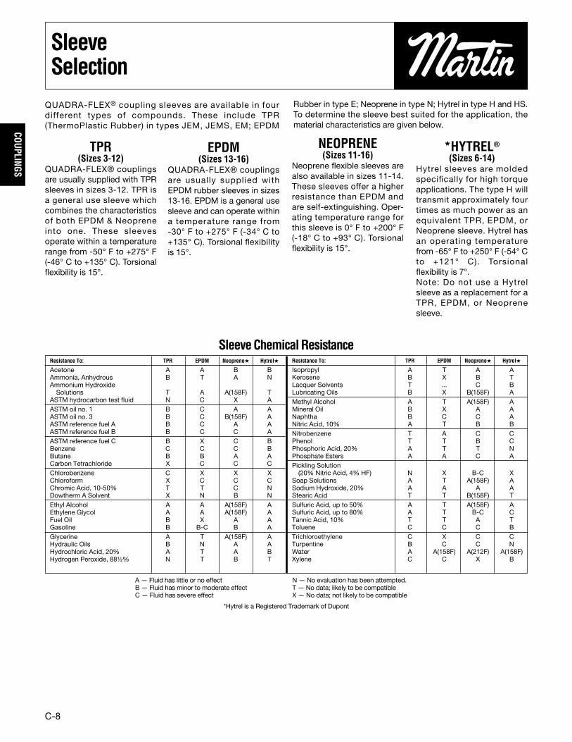
QUADRA-FLEX® coupling sleeves are available in fourdifferent types of compounds. These include TPR(ThermoPlastic Rubber) in types JEM, JEMS, EM; EPDM
Rubber in type E; Neoprene in type N; Hytrel in type H and HS.To determine the sleeve best suited for the application, thematerial characteristics are given below.
Resistance To: TPR EPDM Neoprene� Hytrel�
Acetone A A B BAmmonia, Anhydrous B T A NAmmonium HydroxideSolutions T A A(158F) T
ASTM hydrocarbon test fluid N C X AASTM oil no. 1 B C A AASTM oil no. 3 B C B(158F) AASTM reference fuel A B C A AASTM reference fuel B B C C AASTM reference fuel C B X C BBenzene C C C BButane B B A ACarbon Tetrachloride X C C CChlorobenzene C X X XChloroform X C C CChromic Acid, 10-50% T T C NDowtherm A Solvent X N B NEthyl Alcohol A A A(158F) AEthylene Glycol A A A(158F) AFuel Oil B X A AGasoline B B-C B AGlycerine A T A(158F) AHydraulic Oils B N A AHydrochloric Acid, 20% A T A BHydrogen Peroxide, 88¹⁄₂% N T B T
Resistance To: TPR EPDM Neoprene� Hytrel�
Isopropyl A T A AKerosene B X B TLacquer Solvents T ... C BLubricating Oils B X B(158F) AMethyl Alcohol A T A(158F) AMineral Oil B X A ANaphtha B C C ANitric Acid, 10% A T B BNitrobenzene T A C CPhenol T T B CPhosphoric Acid, 20% A T T NPhosphate Esters A A C APickling Solution(20% Nitric Acid, 4% HF) N X B-C X
Soap Solutions A T A(158F) ASodium Hydroxide, 20% A A A AStearic Acid T T B(158F) TSulfuric Acid, up to 50% A T A(158F) ASulfuric Acid, up to 80% A T B-C CTannic Acid, 10% T T A TToluene C C C BTrichloroethylene C X C CTurpentine B C C NWater A A(158F) A(212F) A(158F)Xylene C C X B
SleeveChemicalResistance
A — Fluid has little or no effectB — Fluid has minor to moderate effectC — Fluid has severe effect
N — No evaluation has been attempted.T — No data; likely to be compatibleX — No data; not likely to be compatible
*Hytrel is a Registered Trademark of Dupont
C-9
COUP
LING
S
SelectionProcedure
SelectionProcedureWhen the driver is an electric motor with standard speed.
Step 1. Determine Service Factor (SF) Symbol based onequipment listed on page C-10.
Step 2. Determine proper Service Factor from chart at top ofpage C-10.
Step 3. Refer to page C-12 and C-13 for proper selection ofcoupling. Based on chemical resistance and operatingenvironment found on page C-8, select from chart the type ofsleeve material. Find RPM of motor, then, in the column forservice factor determined in Step 2, read down to thecorresponding horsepower of motor being used as the driver.The number listed is the correct coupling size.
Example: A coupling is needed to connect a 25 HPstandard electric motor to a lumber log haul at 1750RPM.1. Service Factor Symbol — H2. Service Factor — 2.03. Coupling Size — 9 with TPR sleeve or 6 with Hytrel
Sleeve
Step 4. Select flanges from pages C-15 thru C-19, checkcoupling bore size range for proper shaft fit.
� NOTE: Do not oversize coupling hub — will causepremature wear of element.
When the driver is other than an electric motor or the speedsare different than those shown in the chart on page C-11.
Step 1. Follow steps 1 & 2 in previous procedure.
Step 2. Calculate Horsepower at 100 RPM as follows:
HP at 100 RPM = HP x Service Factor x 100coupling RPM
Step 3. Select coupling size from Tables A or C. Find a HPequal to or greater than the HP/100 RPM
Step 4. Check Maximum bore to be sure that both shaft sizesdo not exceed figure listed for size selected in step 4. Ifmaximum is exceeded select the next largest size which willallow for bore size. Do not exceed maximum RPM for new sizeselected.
Example: A bucket elevator is driven by a motor/reducerand requires a coupling to transmit 14 HP at 1300 RPM.1. Service Factor Symbol — M2. Service Factor — 1.53. HP at 100 RPM = 14 x1.5 x 100 = 1.61 HP/100 RPM
1300
4. Refer to page C-11; under column for 100 RPM therequired 1.61 HP falls between the size 7 (1.2) and thesize 8 (1.8). Correct selection is size 8 with TPR sleeve.Check bore sizes for flanges on pages C-15 thru C-19.
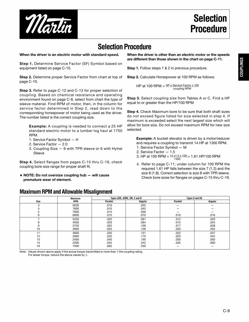
3 9200 .010 .035 — —4 7600 .010 .043 — —5 7600 .015 .056 — —6 6000 .015 .070 .010 .0167 5250 .020 .081 .012 .0208 4500 .020 .094 .015 .0259 3750 .025 .109 .017 .02810 3600 .025 .128 .020 .03211 3600 .032 .151 .022 .03712 2800 .032 .175 .025 .04213 2400 .040 .195 .030 .05014 2200 .045 .242 .035 .06016 1500 .062 .330 — —
Maximum Types JEM, JEMS, EM, E and N Types H and HSSize RPM Parallel Angular Parallel Angular
Note: Values shown above apply if the actual torque transmitted is more than 1⁄4 the coupling rating.For lesser torque, reduce the above values by 1⁄2.
MaximumRPMandAllowableMisalignment

C-10
COUPLINGS
ServiceFactors
ServiceFactorsForQUADRA-FLEX® Couplings
L (LIGHT) 1.25 1.5 1.0 1.5M (MEDIUM) 1.5 2.0 1.25 2.0H (HEAVY) 2.0 2.5 1.5 2.5
Service Factor Electric Motor Electric Motor ReciprocatingSymbol Standard Torque High Torque Turbines Engines
Application SF Symbols
AGITATORS - Paddle, Propeller, Screw . . . . . . . . . LBAND RESAW . . . . . . . . . . . . . . . . . . . . . . . . . . . .MBARGE HAUL PULLER. . . . . . . . . . . . . . . . . . . . . . HBARKING (Lumber). . . . . . . . . . . . . . . . . . . . . . . . . HBAR SCREEN (sewage). . . . . . . . . . . . . . . . . . . . . . LBATCHES (textile) . . . . . . . . . . . . . . . . . . . . . . . . . . LBEATER AND PULPER (paper) . . . . . . . . . . . . . . .MBENDING ROLL (metal) . . . . . . . . . . . . . . . . . . . . .MBLEACHER (paper) . . . . . . . . . . . . . . . . . . . . . . . . . LBLOWERS
Centrifugal, Vane . . . . . . . . . . . . . . . . . . . . LLobe. . . . . . . . . . . . . . . . . . . . . . . . . . . . . .M
BOTTLING MACHINERY. . . . . . . . . . . . . . . . . . . . . LBREW KETTLES (distilling) . . . . . . . . . . . . . . . . . . . LBUCKET ELEVATOR OR CONVEYOR. . . . . . . . . . MCALENDERS
Calender (paper) . . . . . . . . . . . . . . . . . . . .MCalender-super (paper, rubber) . . . . . . . . . H
CANE KNIVES (sugar) . . . . . . . . . . . . . . . . . . . . . .MCARD MACHINE (textile) . . . . . . . . . . . . . . . . . . . . HCAR DUMPERS . . . . . . . . . . . . . . . . . . . . . . . . . . . HCEMENT KILN . . . . . . . . . . . . . . . . . . . . . . . . . . . . HCENTRIFUGAL BLOWERS
COMPRESSORS, FANS or PUMPS . . . . . . . . . LCHEMICAL FEEDERS (sewage) . . . . . . . . . . . . . . . LCHILLER (oil) . . . . . . . . . . . . . . . . . . . . . . . . . . . . .MCHIPPER (paper) . . . . . . . . . . . . . . . . . . . . . . . . . . HCIRCULAR RESAW . . . . . . . . . . . . . . . . . . . . . . . .MCLARIFIER or CLASSIFIER . . . . . . . . . . . . . . . . . . . LCLAY WORKING MACHINERY . . . . . . . . . . . . . . .MCOLLECTORS (sewage) . . . . . . . . . . . . . . . . . . . . . LCOMPRESSORS
Centrifugal . . . . . . . . . . . . . . . . . . . . . . . . . LReciprocating . . . . . . . . . . . . . . . . . . . . . . . *Screw, Lobe . . . . . . . . . . . . . . . . . . . . . . . . L
CONCRETE MIXERS . . . . . . . . . . . . . . . . . . . . . . .MCONVERTING MACHINE (paper) . . . . . . . . . . . . . MCONVEYORS
Apron, Assembly Belt, Flight. . . . . . . . . . . . LOven, Screw . . . . . . . . . . . . . . . . . . . . . . . . LBucket . . . . . . . . . . . . . . . . . . . . . . . . . . . .M
COOKERS- Brewing, Distilling, Food . . . . . . . . . . . LCOOLING TOWER FANS . . . . . . . . . . . . . . . . . . . . HCOUCH (paper) . . . . . . . . . . . . . . . . . . . . . . . . . . .MCRANES & HOISTS . . . . . . . . . . . . . . . . . . . . . . . .M
Heavy Duty Mine . . . . . . . . . . . . . . . . . . . . HCRUSHERS — Cane (sugar), Stone, Ore . . . . . . . . HCUTTER — Paper. . . . . . . . . . . . . . . . . . . . . . . . . . HCYLINDER (paper) . . . . . . . . . . . . . . . . . . . . . . . . . HDEWATERING SCREEN (sewage) . . . . . . . . . . . . M
Application SF Symbols
DISC FEEDER . . . . . . . . . . . . . . . . . . . . . . . . . . . . . LDOUGH MIXER . . . . . . . . . . . . . . . . . . . . . . . . . . .MDRAW BENCH CONVEYOR & Main Drive . . . . . . . HDREDGES
Cable Reel, Pumps . . . . . . . . . . . . . . . . . .MCutter Head Drive, Jig Drive . . . . . . . . . . . HScreen Drive . . . . . . . . . . . . . . . . . . . . . . . HManeuvering and Utility Winch . . . . . . . . . MStacker . . . . . . . . . . . . . . . . . . . . . . . . . . .M
DYNAMOMETER . . . . . . . . . . . . . . . . . . . . . . . . . . LDRYERS (rotary) . . . . . . . . . . . . . . . . . . . . . . . . . .MEDGER (lumber) . . . . . . . . . . . . . . . . . . . . . . . . . . . HELEVATORS
Bucket . . . . . . . . . . . . . . . . . . . . . . . . . . . .MEscalator . . . . . . . . . . . . . . . . . . . . . . . . . . LFreight, Passenger, Service, Man Lift . . . . H
ESCALATORS . . . . . . . . . . . . . . . . . . . . . . . . . . . . LEXTRUDER (metal) . . . . . . . . . . . . . . . . . . . . . . . . . HFANS
Centrifugal . . . . . . . . . . . . . . . . . . . . . . . . . LCooling Tower . . . . . . . . . . . . . . . . . . . . . . HForced Draft, Large Industrial, Mine . . . . . M
FEEDERSApron, Belt, Disc . . . . . . . . . . . . . . . . . . . . . LReciprocating . . . . . . . . . . . . . . . . . . . . . . . HScrew. . . . . . . . . . . . . . . . . . . . . . . . . . . . .M
FILTER, PRESS-OIL. . . . . . . . . . . . . . . . . . . . . . . .MGENERATORS
Uniform load . . . . . . . . . . . . . . . . . . . . . . . . LVarying load, Holst. . . . . . . . . . . . . . . . . . .MWelders . . . . . . . . . . . . . . . . . . . . . . . . . . . H
GRIT COLLECTOR (sewage). . . . . . . . . . . . . . . . . . LGRIZZLY. . . . . . . . . . . . . . . . . . . . . . . . . . . . . . . . . HHAMMERMILL
Light Duty, Intermittent . . . . . . . . . . . . . . .MHeavy Duty, Continuous. . . . . . . . . . . . . . . H
HOISTSHeavy Duty . . . . . . . . . . . . . . . . . . . . . . . . . HMedium Duty . . . . . . . . . . . . . . . . . . . . . . .M
JORDAN (paper) . . . . . . . . . . . . . . . . . . . . . . . . . . . HKILN, ROTARY . . . . . . . . . . . . . . . . . . . . . . . . . . . . HLAUNDRY WASHER or TUMBLER. . . . . . . . . . . . . HLINE SHAFTS . . . . . . . . . . . . . . . . . . . . . . . . . . . . . LLOG HAUL (lumber) . . . . . . . . . . . . . . . . . . . . . . . . HLOOM (textile) . . . . . . . . . . . . . . . . . . . . . . . . . . . .MMACHINE TOOLS, MAIN DRIVE . . . . . . . . . . . . . .MMANGLE (textile) . . . . . . . . . . . . . . . . . . . . . . . . . . LMASH TUBS (distilling) . . . . . . . . . . . . . . . . . . . . . . LMEAT GRINDER. . . . . . . . . . . . . . . . . . . . . . . . . . .MMETAL FORMING MACHINES . . . . . . . . . . . . . . .M
Application SF Symbols
MILLSBall, Pebble, Rod, Tube . . . . . . . . . . . . . . . HRubber, Tumbling. . . . . . . . . . . . . . . . . . . . HDryer and Cooler . . . . . . . . . . . . . . . . . . . .M
MIXERConcrete, Muller . . . . . . . . . . . . . . . . . . . .MBanbury . . . . . . . . . . . . . . . . . . . . . . . . . . . H
ORE CRUSHER . . . . . . . . . . . . . . . . . . . . . . . . . . . HOVEN CONVEYOR . . . . . . . . . . . . . . . . . . . . . . . . . LPLANER (metal or wood) . . . . . . . . . . . . . . . . . . . .MPRESSES
Brick, Brlquette Machine . . . . . . . . . . . . . . HNotchlng, Paper, Punch, Printing . . . . . . . M
PUG MILL. . . . . . . . . . . . . . . . . . . . . . . . . . . . . . . .MPULP GRINDER (paper) . . . . . . . . . . . . . . . . . . . . . HPULVERIZERS
Hammermill — light duty, Roller . . . . . . . . MHammermill — heavy duty, Hog. . . . . . . . . H
PUMPSCentrifugal, Axial . . . . . . . . . . . . . . . . . . . . LGear, Lobe, Vane . . . . . . . . . . . . . . . . . . .MReciprocating — sgl. or dbl. acting . . . . . . *
REEL, REWINDER (paper) CABLE . . . . . . . . . . . . MROD MILL . . . . . . . . . . . . . . . . . . . . . . . . . . . . . . . HSAWDUST CONVEYOR . . . . . . . . . . . . . . . . . . . . . LSCREENS
Air Washing, Water . . . . . . . . . . . . . . . . . . LRotary for coal or sand . . . . . . . . . . . . . . .MVibrating . . . . . . . . . . . . . . . . . . . . . . . . . . H
SCREW CONVEYOR . . . . . . . . . . . . . . . . . . . . . . . LSLAB CONVEYOR (lumber) . . . . . . . . . . . . . . . . .MSLITTERS (metal) . . . . . . . . . . . . . . . . . . . . . . . . . .MSOAPERS (textile) . . . . . . . . . . . . . . . . . . . . . . . . . . LSORTING TABLE (lumber) . . . . . . . . . . . . . . . . . . .MSPINNER (textile) . . . . . . . . . . . . . . . . . . . . . . . . .MSTOKER . . . . . . . . . . . . . . . . . . . . . . . . . . . . . . . . . LSUCTION ROLL (paper) . . . . . . . . . . . . . . . . . . . .MTENTER FRAMES (textile) . . . . . . . . . . . . . . . . . . .MTIRE BUILDING MACHINES. . . . . . . . . . . . . . . . . . HTIRE & TUBE PRESS OPENER . . . . . . . . . . . . . . . LTUMBLING BARRELS . . . . . . . . . . . . . . . . . . . . . . HWASHER and THICKENER (paper) . . . . . . . . . . . .MWINCHES . . . . . . . . . . . . . . . . . . . . . . . . . . . . . . .MWINDERS, Paper, Textile, Wire . . . . . . . . . . . . . . . MWINDLASS . . . . . . . . . . . . . . . . . . . . . . . . . . . . . .MWIRE
Drawing . . . . . . . . . . . . . . . . . . . . . . . . . . . HWinding . . . . . . . . . . . . . . . . . . . . . . . . . . .M
WOODWORKING MACHINERY . . . . . . . . . . . . . . . L
Table1
* Consult Factory

C-11
COUP
LING
S
CouplingRatings
3� HYTREL — — — — — — — —
4� HYTREL — — — — — — — —
5� HYTREL — — — — — — — —
6 HYTREL 2.9 25.0 33.0 50.0 100.0 1800 10000 6000
7 HYTREL 4.6 39.0 53.0 80.0 160.0 2875 20000 5250
8 HYTREL 7.2 62.0 84.0 126.0 252.0 4530 30000 4500
9 HYTREL 11.4 98.0 132.0 200.0 400.0 7200 47500 3750
10 HYTREL 18.0 155.0 209.0 315.0 630.0 11350 100000 3600
11 HYTREL 28.6 246.0 331.0 500.0 1000.0 18000 125000 3600
12 HYTREL 50.0 430.0 580.0 875.0 — 31500 225000 2800
13 HYTREL 75.0 645.0 870.0 1312.0 — 47268 368900 2400
14 HYTREL 115.0 986.0 1334.0 2013.0 — 72480 593250 2200
CouplingRatingsTable2A
3 TPR .10 .8 1.1 1.7 3.3 60 229 9200
4 TPR .19 1.6 2.2 3.3 6.7 120 458 7600
5 TPR .38 3.3 4.4 6.7 13.0 240 916 7600
6 TPR .71 6.1 8.3 12.5 25.0 450 1718 6000
7 TPR 1.20 10.0 13.0 20.0 40.0 725 2769 5250
8 TPR 1.80 16.0 20.0 32.0 63.0 1135 4335 4500
9 TPR 2.80 25.0 33.0 50.0 100.0 1800 6875 3750
10 TPR 4.60 39.0 53.0 80.0 160.0 2875 10980 3600
11 TPR 7.20 62.0 83.0 126.0 252.0 4530 17300 3600
12 TPR 11.40 98.0 132.0 200.0 — 7200 27500 2800
13 EPDM & Neoprene 18.00 155.0 209.0 315.0 — 11350 43350 2400
14 EPDM & Neoprene 28.60 246.0 331.0 500.0 — 18000 68755 2200
16 EPDM 75.00 645.0 870.0 — — 47250 180480 1500
Basic HP Ratings Rated Torsional •Coupling Sleeve Per Given RPM Torque Stiffness Factor MaximumSize Construction 100 860 1160 1750 3500 (in.-lb.) (in.-lb./radians) RPM
Basic HP Ratings Rated Torsional •Coupling Sleeve Per Given RPM Torque Stiffness Factor MaximumSize Construction 100 860 1160 1750 3500 (in.-lb.) (in.-lb./radians) RPM
Table2C
� Hytrel sleeves are available on a made-to-order basis. Consult factory.• Values shown are for an ambient temperature of 75° F (24° C).
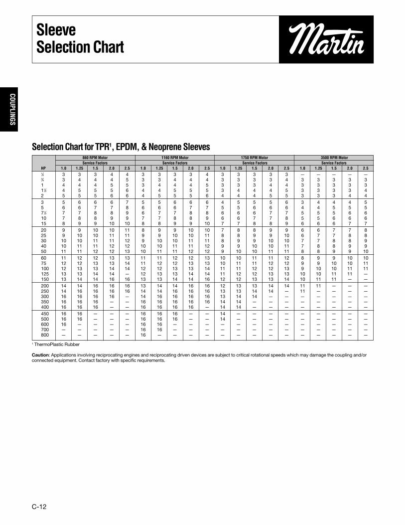
ThermoPlasticRubber (TPR), EPDM&Neoprene
Hytrel
C-12
COUPLINGS
SleeveSelectionChart
1⁄2 3 3 3 4 4 3 3 3 3 4 3 3 3 3 3 — — — — —3⁄4 3 4 4 4 5 3 3 4 4 4 3 3 3 3 4 3 3 3 3 31 4 4 4 5 5 3 4 4 4 5 3 3 3 4 4 3 3 3 3 311⁄2 4 5 5 5 6 4 4 5 5 5 3 4 4 4 5 3 3 3 3 42 5 5 5 6 6 4 5 5 5 6 4 4 4 5 5 3 3 3 4 43 5 6 6 6 7 5 5 6 6 6 4 5 5 5 6 3 4 4 4 55 6 6 7 7 8 6 6 6 7 7 5 5 6 6 6 4 4 5 5 571⁄2 7 7 8 8 9 6 7 7 8 8 6 6 6 7 7 5 5 5 6 610 7 8 8 9 9 7 7 8 8 9 6 6 7 7 8 5 5 6 6 615 8 9 9 10 10 8 8 9 9 10 7 7 8 8 9 6 6 6 7 720 9 9 10 10 11 8 9 9 10 10 7 8 8 9 9 6 6 7 7 825 9 10 10 11 11 9 9 10 10 11 8 8 9 9 10 6 7 7 8 830 10 10 11 11 12 9 10 10 11 11 8 9 9 10 10 7 7 8 8 940 10 11 11 12 12 10 10 11 11 12 9 9 10 10 11 7 8 8 9 950 11 11 12 12 13 10 11 11 12 12 9 10 10 11 11 8 8 9 9 1060 11 12 12 13 13 11 11 12 12 13 10 10 11 11 12 8 9 9 10 1075 12 12 13 13 14 11 12 12 13 13 10 11 11 12 12 9 9 10 10 11100 12 13 13 14 14 12 12 13 13 14 11 11 12 12 13 9 10 10 11 11125 13 13 14 14 — 12 13 13 14 14 11 12 12 13 13 10 10 11 11 —150 13 14 14 16 16 13 13 14 14 16 12 12 13 13 14 10 11 11 — —200 14 14 16 16 16 13 14 14 16 16 12 13 13 14 14 11 11 — — —250 14 16 16 16 16 14 14 16 16 16 13 13 14 14 — 11 — — — —300 16 16 16 16 — 14 16 16 16 16 13 14 14 — — — — — — —350 16 16 16 — — 16 16 16 16 16 14 14 — — — — — — — —400 16 16 16 — — 16 16 16 16 — 14 14 — — — — — — — —450 16 16 — — — 16 16 16 — — 14 — — — — — — — — —500 16 16 — — — 16 16 16 — — 14 — — — — — — — — —600 16 — — — — 16 16 — — — — — — — — — — — — —700 — — — — — 16 16 — — — — — — — — — — — — —800 — — — — — 16 — — — — — — — — — — — — — —
SelectionChart for TPR1, EPDM,&NeopreneSleeves860 RPM Motor 1160 RPM Motor 1750 RPM Motor 3500 RPM MotorService Factors Service Factors Service Factors Service Factors
HP 1.0 1.25 1.5 2.0 2.5 1.0 1.25 1.5 2.0 2.5 1.0 1.25 1.5 2.0 2.5 1.0 1.25 1.5 2.0 2.5
1 ThermoPlastic Rubber
Caution: Applications involving reciprocating engines and reciprocating driven devices are subject to critical rotational speeds which may damage the coupling and/orconnected equipment. Contact factory with specific requirements.
C-13
COUP
LING
S
HytrelSelectionChart
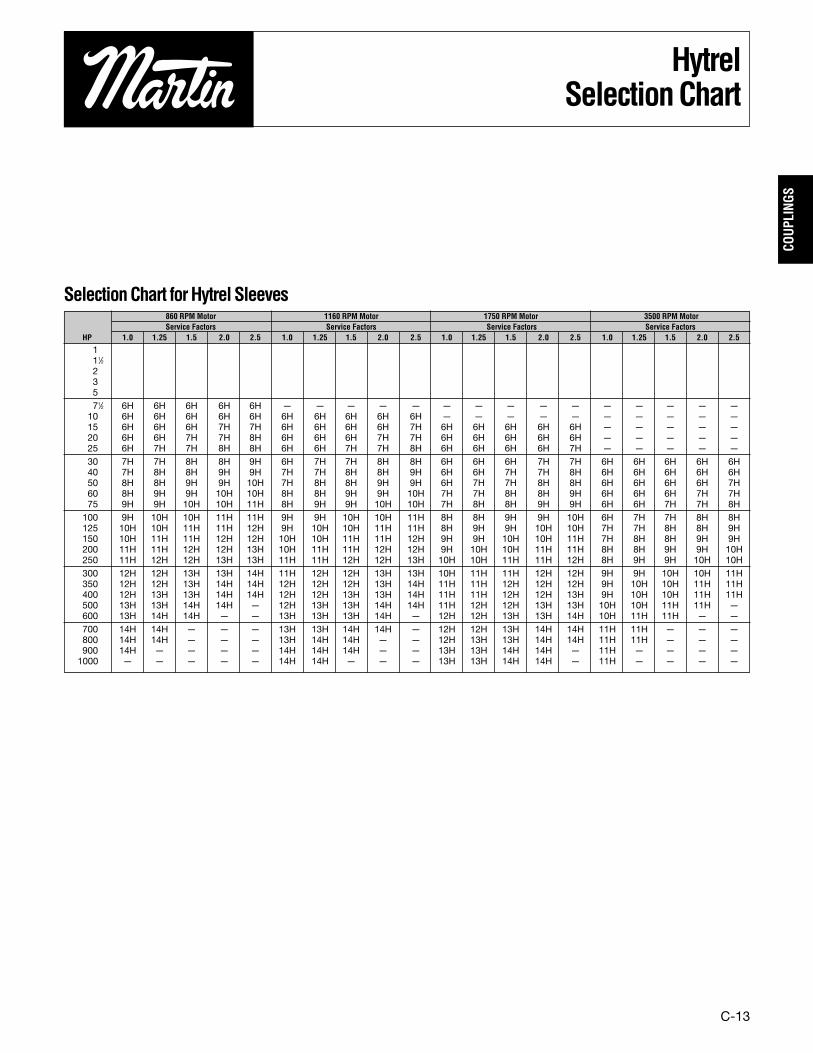
SelectionChart forHytrel Sleeves
111⁄223571⁄2 6H 6H 6H 6H 6H — — — — — — — — — — — — — — —10 6H 6H 6H 6H 6H 6H 6H 6H 6H 6H — — — — — — — — — —15 6H 6H 6H 7H 7H 6H 6H 6H 6H 7H 6H 6H 6H 6H 6H — — — — —20 6H 6H 7H 7H 8H 6H 6H 6H 7H 7H 6H 6H 6H 6H 6H — — — — —25 6H 7H 7H 8H 8H 6H 6H 7H 7H 8H 6H 6H 6H 6H 7H — — — — —30 7H 7H 8H 8H 9H 6H 7H 7H 8H 8H 6H 6H 6H 7H 7H 6H 6H 6H 6H 6H40 7H 8H 8H 9H 9H 7H 7H 8H 8H 9H 6H 6H 7H 7H 8H 6H 6H 6H 6H 6H50 8H 8H 9H 9H 10H 7H 8H 8H 9H 9H 6H 7H 7H 8H 8H 6H 6H 6H 6H 7H60 8H 9H 9H 10H 10H 8H 8H 9H 9H 10H 7H 7H 8H 8H 9H 6H 6H 6H 7H 7H75 9H 9H 10H 10H 11H 8H 9H 9H 10H 10H 7H 8H 8H 9H 9H 6H 6H 7H 7H 8H100 9H 10H 10H 11H 11H 9H 9H 10H 10H 11H 8H 8H 9H 9H 10H 6H 7H 7H 8H 8H125 10H 10H 11H 11H 12H 9H 10H 10H 11H 11H 8H 9H 9H 10H 10H 7H 7H 8H 8H 9H150 10H 11H 11H 12H 12H 10H 10H 11H 11H 12H 9H 9H 10H 10H 11H 7H 8H 8H 9H 9H200 11H 11H 12H 12H 13H 10H 11H 11H 12H 12H 9H 10H 10H 11H 11H 8H 8H 9H 9H 10H250 11H 12H 12H 13H 13H 11H 11H 12H 12H 13H 10H 10H 11H 11H 12H 8H 9H 9H 10H 10H300 12H 12H 13H 13H 14H 11H 12H 12H 13H 13H 10H 11H 11H 12H 12H 9H 9H 10H 10H 11H350 12H 12H 13H 14H 14H 12H 12H 12H 13H 14H 11H 11H 12H 12H 12H 9H 10H 10H 11H 11H400 12H 13H 13H 14H 14H 12H 12H 13H 13H 14H 11H 11H 12H 12H 13H 9H 10H 10H 11H 11H500 13H 13H 14H 14H — 12H 13H 13H 14H 14H 11H 12H 12H 13H 13H 10H 10H 11H 11H —600 13H 14H 14H — — 13H 13H 13H 14H — 12H 12H 13H 13H 14H 10H 11H 11H — —700 14H 14H — — — 13H 13H 14H 14H — 12H 12H 13H 14H 14H 11H 11H — — —800 14H 14H — — — 13H 14H 14H — — 12H 13H 13H 14H 14H 11H 11H — — —900 14H — — — — 14H 14H 14H — — 13H 13H 14H 14H — 11H — — — —1000 — — — — — 14H 14H — — — 13H 13H 14H 14H — 11H — — — —
860 RPM Motor 1160 RPM Motor 1750 RPM Motor 3500 RPM MotorService Factors Service Factors Service Factors Service Factors
HP 1.0 1.25 1.5 2.0 2.5 1.0 1.25 1.5 2.0 2.5 1.0 1.25 1.5 2.0 2.5 1.0 1.25 1.5 2.0 2.5
C-14
COUPLINGS
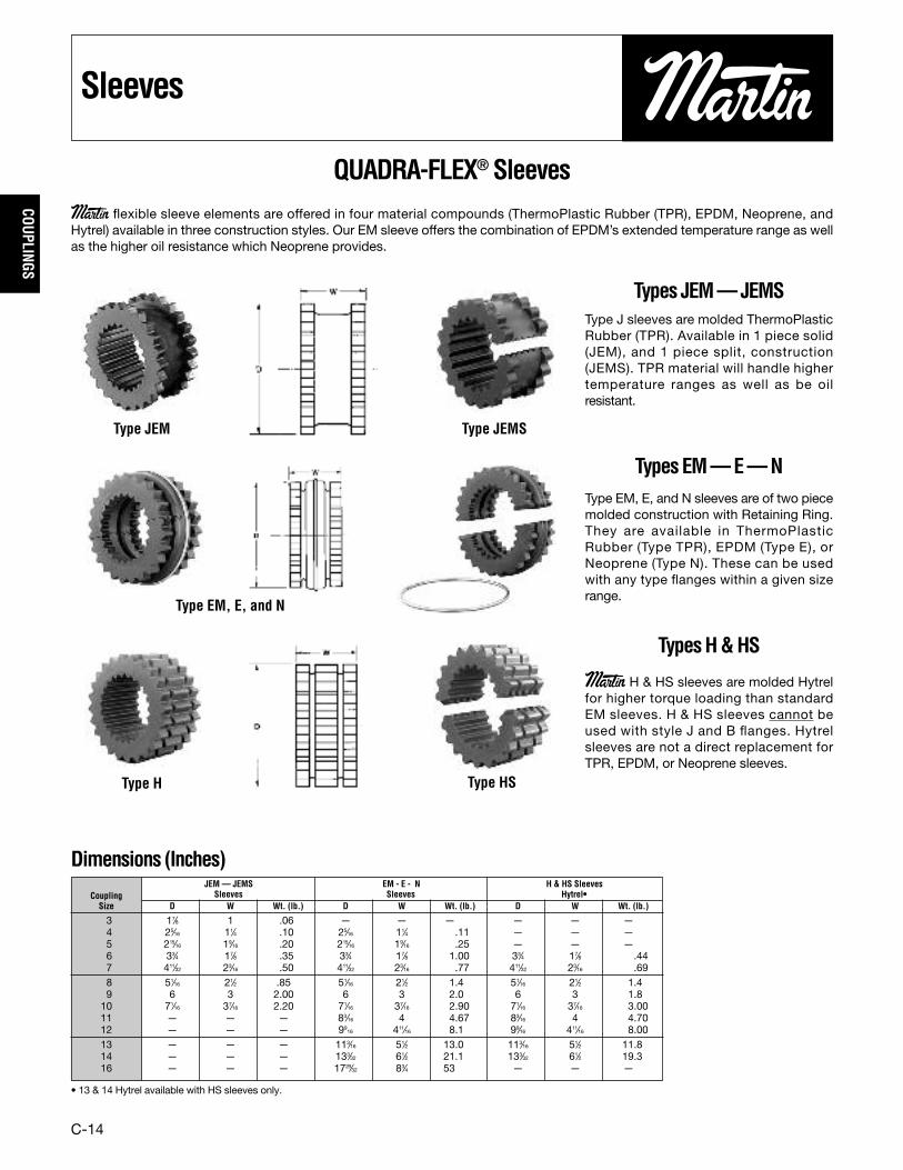
Sleeves
Type J sleeves are molded ThermoPlasticRubber (TPR). Available in 1 piece solid(JEM), and 1 piece split, construction(JEMS). TPR material will handle highertemperature ranges as well as be oilresistant.
Types JEM—JEMS
Type EM, E, and N sleeves are of two piecemolded construction with Retaining Ring.They are available in ThermoPlasticRubber (Type TPR), EPDM (Type E), orNeoprene (Type N). These can be usedwith any type flanges within a given sizerange.
TypesEM—E—N
Martin H & HS sleeves are molded Hytrelfor higher torque loading than standardEM sleeves. H & HS sleeves cannot beused with style J and B flanges. Hytrelsleeves are not a direct replacement forTPR, EPDM, or Neoprene sleeves.
TypesH&HS
JEM— JEMS EM - E - N H & HS SleevesCoupling Sleeves Sleeves Hytrel•Size D W Wt. (lb.) D W Wt. (lb.) D W Wt. (lb.)
3 17⁄8 1 .06 — — — — — —4 25⁄16 11⁄4 .10 25⁄16 11⁄4 .11 — — —5 215⁄16 19⁄16 .20 215⁄16 19⁄16 .25 — — —6 33⁄4 17⁄8 .35 33⁄4 17⁄8 1.00 33⁄4 17⁄8 .447 411⁄32 23⁄16 .50 411⁄32 23⁄16 .77 411⁄32 23⁄16 .698 51⁄16 21⁄2 .85 51⁄16 21⁄2 1.4 51⁄16 21⁄2 1.49 6 3 2.00 6 3 2.0 6 3 1.810 71⁄16 37⁄16 2.20 71⁄16 37⁄16 2.90 71⁄16 37⁄16 3.0011 — — — 83⁄16 4 4.67 83⁄16 4 4.7012 — — — 99
16 411⁄16 8.1 99⁄16 411⁄16 8.0013 — — — 113⁄16 51⁄2 13.0 113⁄16 51⁄2 11.814 — — — 133⁄32 61⁄2 21.1 133⁄32 61⁄2 19.316 — — — 1729⁄32 83⁄4 53 — — —
Dimensions (Inches)
QUADRA-FLEX® SleevesMartin flexible sleeve elements are offered in four material compounds (ThermoPlastic Rubber (TPR), EPDM, Neoprene, andHytrel) available in three construction styles. Our EM sleeve offers the combination of EPDM’s extended temperature range as wellas the higher oil resistance which Neoprene provides.
Type JEM Type JEMS
Type HSType H
Type EM, E, and N
• 13 & 14 Hytrel available with HS sleeves only.

C-15
COUP
LING
S
Type JFlanges
QUADRA-FLEX® TypeJFlanges
QUADRA-FLEX® TypeJFlangesMartin Type J Flanges are supplied bored to size withstandard keyway and two setscrews to slip fit onstandard shafting.
Dimensions (Inches)
3J 13⁄16 2.062 7⁄16 3⁄8 11⁄4 2 3⁄8 9⁄16 .26 3⁄8**- 1⁄2 - 5⁄8 - 3⁄4 3⁄4 — — —13⁄16 2.062 7⁄16 3⁄8 11⁄2 2 3⁄8 9⁄16 .26 7⁄8 7⁄8 — — —
4J 7⁄8 2.460 7⁄16 5⁄8 15⁄8 23⁄8 7⁄16 3⁄4 .47 1⁄2 - 5⁄8 - 3⁄4 - 7⁄8 - 15⁄16 - 1 1 15 20 255J 11⁄16 3.250 15⁄32 3⁄4 17⁄8 27⁄8 19⁄32 31⁄32 .86 1⁄2 - 5⁄8 - 3⁄4 - 7⁄8 - 15⁄16 - 1 - 11⁄8 11⁄8 — — —6J 17⁄32 4.000 19⁄32 7⁄8 115⁄16 35⁄16 5⁄8 13⁄32 1.73 5⁄8 - 3⁄4 - 7⁄8 - 15⁄16 - 1 — — — —
17⁄32 4.000 19⁄32 7⁄8 21⁄2 35⁄16 5⁄8 13⁄32 1.70 11⁄8 - 13⁄16 - 11⁄4 - 13⁄8 13⁄8 — — —
Coupling Dimensions Weight Finished Bore Sizes• Max.Size C D E G H L T X (lbs.)� (Inches) Bore Millimeters
* Approximate weight for each flange.** 3/8” Bore has no Keyway• J flanges can be rebored if necessary.
Type J Flanges use the Martin JEM 1 Piece,theMartin JEMS 1 piece split and the Martin EM 2 piecesplit sleeves.(Note: Hytrel sleeves are not intended for use withthis type of flange.)
C-16
COUPLINGS
TypeSFlanges
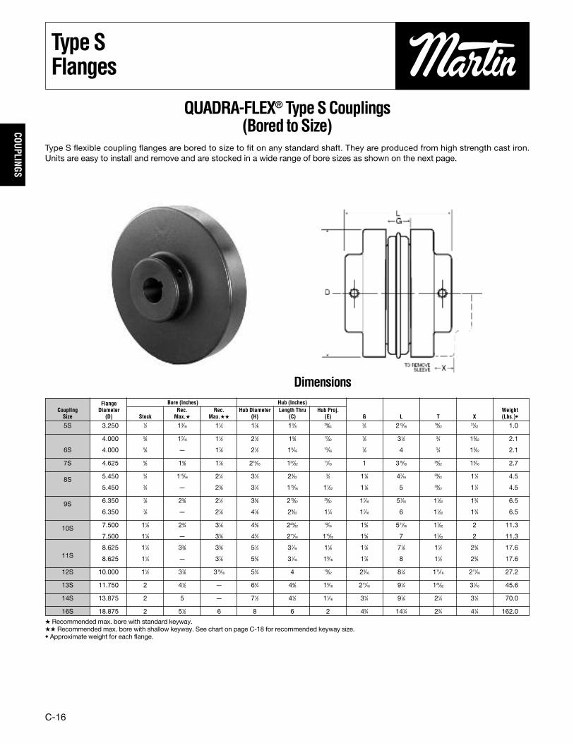
QUADRA-FLEX® TypeSCouplings(Bored toSize)
Type S flexible coupling flanges are bored to size to fit on any standard shaft. They are produced from high strength cast iron.Units are easy to install and remove and are stocked in a wide range of bore sizes as shown on the next page.
5S 3.250 1⁄2 13⁄16 11⁄4 17⁄8 13⁄8 29⁄64 3⁄4 213⁄16 19⁄32 31⁄32 1.0
4.000 5⁄8 17⁄16 11⁄2 21⁄2 15⁄8 17⁄32 7⁄8 31⁄2 3⁄4 13⁄32 2.1
6S 4.000 5⁄8 — 17⁄8 21⁄2 19⁄16 13⁄16 7⁄8 4 3⁄4 13⁄32 2.1
7S 4.625 5⁄8 15⁄8 17⁄8 213⁄16 127⁄32 11⁄16 1 315⁄16 25⁄32 15⁄16 2.7
8S 5.450 3⁄4 115⁄16 21⁄4 31⁄4 23⁄32 3⁄4 11⁄8 47⁄16 29⁄32 11⁄2 4.5
5.450 3⁄4 — 23⁄8 31⁄4 115⁄16 11⁄32 11⁄8 5 29⁄32 11⁄2 4.5
9S 6.350 7⁄8 23⁄8 21⁄2 35⁄8 213⁄32 25⁄32 17⁄16 51⁄16 11⁄32 13⁄4 6.5
6.350 7⁄8 — 27⁄8 41⁄8 29⁄32 11⁄4 17⁄16 6 11⁄32 13⁄4 6.5
10S 7.500 11⁄8 23⁄4 31⁄8 43⁄8 223⁄32 13⁄16 15⁄8 511⁄16 17⁄32 2 11.3
7.500 11⁄8 — 33⁄8 43⁄4 211⁄16 115⁄32 15⁄8 7 17⁄32 2 11.3
8.625 11⁄4 33⁄8 35⁄8 51⁄4 37⁄16 11⁄8 17⁄8 71⁄8 11⁄2 23⁄8 17.611S 8.625 11⁄4 — 37⁄8 55⁄8 31⁄16 19⁄16 17⁄8 8 11⁄2 23⁄8 17.6
12S 10.000 11⁄2 37⁄8 315⁄16 53⁄4 4 19⁄32 25⁄16 81⁄4 111⁄16 211⁄16 27.2
13S 11.750 2 41⁄2 — 63⁄4 43⁄8 15⁄16 211⁄16 91⁄4 131⁄32 31⁄16 45.6
14S 13.875 2 5 — 71⁄2 41⁄2 11⁄16 31⁄4 97⁄8 21⁄4 31⁄2 70.0
16S 18.875 2 51⁄2 6 8 6 2 43⁄4 141⁄4 23⁄4 41⁄4 162.0
Flange Bore (Inches) Hub (Inches)Coupling Diameter Rec. Rec. Hub Diameter Length Thru Hub Proj. WeightSize (D) Stock Max.� Max.�� (H) (C) (E) G L T X (Lbs.)•
� Recommended max. bore with standard keyway.�� Recommended max. bore with shallow keyway. See chart on page C-18 for recommended keyway size.• Approximate weight for each flange.
Dimensions
C-17
COUP
LING
S
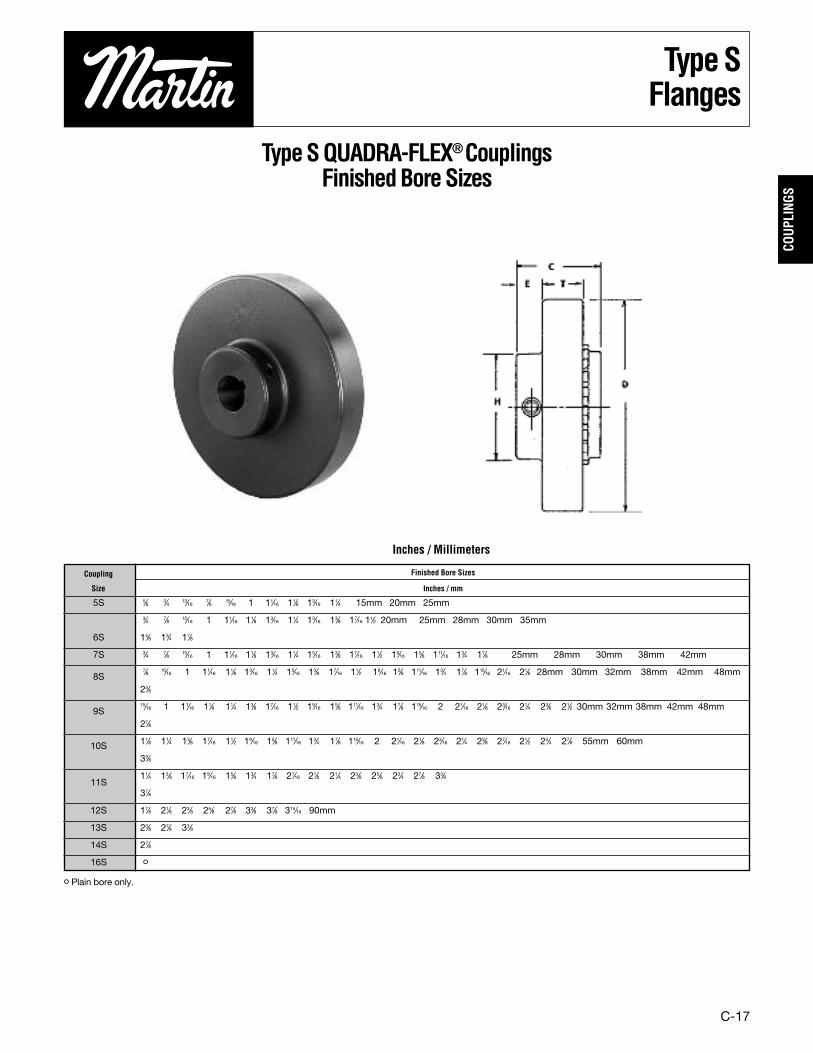
TypeSFlanges
TypeSQUADRA-FLEX®CouplingsFinishedBoreSizes
5S 5⁄8 3⁄4 13⁄16 7⁄8 15⁄16 1 11⁄16 11⁄8 13⁄16 11⁄4 15mm 20mm 25mm
3⁄4 7⁄8 15⁄16 1 11⁄16 11⁄8 13⁄16 11⁄4 15⁄16 13⁄8 17⁄16 11⁄2 20mm 25mm 28mm 30mm 35mm
6S 15⁄8 13⁄4 17⁄8
7S 3⁄4 7⁄8 15⁄16 1 11⁄16 11⁄8 13⁄16 11⁄4 15⁄16 13⁄8 17⁄16 11⁄2 19⁄16 15⁄8 111⁄16 13⁄4 17⁄8 25mm 28mm 30mm 38mm 42mm
8S7⁄8 15⁄16 1 11⁄16 11⁄8 13⁄16 11⁄4 15⁄16 13⁄8 17⁄16 11⁄2 19⁄16 15⁄8 111⁄16 13⁄4 17⁄8 115⁄16 21⁄16 21⁄8 28mm 30mm 32mm 38mm 42mm 48mm
23⁄8
9S15⁄16 1 11⁄16 11⁄8 11⁄4 13⁄8 17⁄16 11⁄2 19⁄16 15⁄8 111⁄16 13⁄4 17⁄8 115⁄16 2 21⁄16 21⁄8 23⁄16 21⁄4 23⁄8 21⁄2 30mm 32mm 38mm 42mm 48mm
27⁄8
10S 11⁄8 11⁄4 13⁄8 17⁄16 11⁄2 19⁄16 15⁄8 111⁄16 13⁄4 17⁄8 115⁄16 2 21⁄16 21⁄8 23⁄16 21⁄4 23⁄8 27⁄16 21⁄2 23⁄4 27⁄8 55mm 60mm
33⁄8
11S11⁄4 13⁄8 17⁄16 19⁄16 15⁄8 13⁄4 17⁄8 21⁄16 21⁄8 21⁄4 23⁄8 25⁄8 23⁄4 27⁄8 33⁄8
37⁄8
12S 17⁄8 21⁄8 23⁄8 25⁄8 27⁄8 33⁄8 37⁄8 315⁄16 90mm
13S 23⁄8 27⁄8 33⁄8
14S 27⁄8
16S o
Coupling Finished Bore Sizes
Size Inches / mm
o Plain bore only.
Inches / Millimeters

C-18
COUPLINGS
KeyseatDimensions
StandardKeywayDimensions
1⁄2-9⁄16 1⁄8 1⁄165⁄8-7⁄8 3⁄16 3⁄32
15⁄16-11⁄4 1⁄4 1⁄815⁄16-13⁄8 5⁄16 5⁄3217⁄16-13⁄4 3⁄8 3⁄16113⁄16-23⁄4 1⁄2 1⁄425⁄16-23⁄4 5⁄8 5⁄16213⁄16-31⁄4 3⁄4 3⁄835⁄16-33⁄4 7⁄8 7⁄16313⁄16-41⁄2 1 1⁄249⁄16-51⁄2 11⁄4 5⁄859⁄16-61⁄2 11⁄2 3⁄4
UP to 1 +.0000 to +.001011⁄16 to 21⁄8 +.0000 to +.001523⁄16 to 25⁄8 +.0000 to +.0020211⁄16 to 311⁄16 +.0000 to +.002533⁄4 to 43⁄4 +.0000 to +.0030413⁄16 to 6 +.0000 to +.0035
6S 21⁄2 15⁄16 15⁄83⁄8 x 1⁄8 3⁄8 x 5⁄16 x 11⁄4 13⁄4 3⁄8 x 1⁄16 3⁄8 x 1⁄4 x 11⁄4 17⁄8 1⁄2 x 1⁄16 1⁄2 x 5⁄16 x 11⁄2213⁄16 19⁄16 3⁄8 x 1⁄8
7S 213⁄16 127⁄32 17⁄8 1⁄2 x 1⁄8 1⁄2 x 3⁄8 x 113⁄168S 31⁄4 23⁄16 21⁄8 1⁄2 x 3⁄16 1⁄2 x 7⁄18 x 21⁄16 23⁄8 5⁄8 x 1⁄8 5⁄8 x 7⁄16 x 115⁄168S 31⁄4 115⁄16 21⁄8 1⁄2 x 3⁄16 1⁄2 x 7⁄18 x 21⁄16 23⁄8 5⁄8 x 1⁄8 5⁄8 x 7⁄16 x 115⁄16
9S 35⁄8 213⁄32 21⁄2 5⁄8 x 3⁄16 5⁄8 x 3⁄8 x 23⁄8 27⁄8 3⁄4 x 1⁄8 3⁄4 x 1⁄2 x 21⁄1641⁄8 29⁄32 21⁄2 5⁄8 x 3⁄16 5⁄8 x 3⁄8 x 23⁄8 27⁄8 3⁄4 x 1⁄8 3⁄4 x 1⁄2 x 21⁄16
10S 43⁄8 221⁄32 27⁄8 3⁄4 x 1⁄4 3⁄4 x 5⁄8 x 211⁄16 33⁄8 7⁄8 x 3⁄16 7⁄8 x 3⁄8 x 211⁄1643⁄4 211⁄16 27⁄8 3⁄4 x 1⁄4 3⁄4 x 5⁄8 x 211⁄16 33⁄8 7⁄8 x 3⁄16 7⁄8 x 3⁄8 x 211⁄1631⁄4 37⁄16 37⁄8 1 x 1⁄4 1 x 3⁄4 x 3
11S 47⁄8 37⁄16 37⁄8 1 x 1⁄4 1 x 3⁄4 x 351⁄4 37⁄16 37⁄8 1 x 1⁄4 1 x 3⁄4 x 355⁄8 31⁄16 37⁄8 1 x 1⁄4 1 x 3⁄4 x 333⁄4 4 315⁄16 1 x 1⁄4 1 x 3⁄4 x 315⁄16
12S 47⁄8 4 315⁄16 1 x 1⁄4 1 x 3⁄4 x 315⁄1653⁄4 4 315⁄16 1 x 1⁄4 1 x 3⁄4 x 315⁄16
Shaft Diameter Width Depth
BoreTolerances forTypes JandSFlanges,SCHubs
Bore (Inch) Tolerance (Inch)
Coupling Hub Dia. Length Thru Shallow Keyseat DimensionsSize (H) (C) Bore Keyway Key Bore Keyway Key Bore Keyway Key
ShallowKeyseatDimensions
These bores provide a slip fit.

C-19
COUP
LING
S
TypeBFlanges
TypeBBushedQUADRA-FLEX®
FlangesType B flanges are made of high quality cast iron. Thesame high strength cast iron used in the Type S andSC QUADRA-FLEX flanges. Type B is designed toaccommodate Martin QD bushings for easyinstallation and removal. Type B flanges are notintended for use with Hytrel sleeves.
BushingsMartin QD bushings offer convenient mounting of theflange to the shaft securely without setscrews. Theyare tapered and are split through both the bushingflange and taper to provide a clamp fit, eliminatingwobble, vibration, and fretting corrosion. This is thesame bushing used in Martin sprockets and sheavesand is readily available.
6B JA 117⁄32 1 4.000 7⁄16 2 7⁄8 35⁄16 25⁄32 13⁄32 13⁄16 1.7 .97B JA 119⁄32 1 4.625 7⁄16 2 1 37⁄16 25⁄32 15⁄16 13⁄16 2.0 1.08B SH 127⁄32 11⁄4 5.450 1⁄2 211⁄16 17⁄16 315⁄16 29⁄32 11⁄2 15⁄8 3.1 1.09B SD 23⁄16 113⁄16 6.350 7⁄16 33⁄16 17⁄16 45⁄8 11⁄32 13⁄4 115⁄16 4.9 1.510B SK 127⁄32 17⁄8 7.500 5⁄8 37⁄8 15⁄8 55⁄16 17⁄32 2 21⁄2 7.0 2.011B SF 21⁄8 2 8.625 5⁄8 45⁄8 17⁄8 61⁄8 11⁄2 23⁄8 23⁄4 11.8 3.012B E 211⁄16 25⁄8 10.000 7⁄8 6 25⁄16 77⁄16 111⁄16 211⁄16 37⁄16 17.2 10.013B F 311⁄16 35⁄8 11.750 1 65⁄8 211⁄16 85⁄8 131⁄32 3 315⁄16 30.5 11.514B F 311⁄16 35⁄8 13.875 1 65⁄8 31⁄4 93⁄4 21⁄4 31⁄2 315⁄16 51.0 11.516B J 43⁄4 41⁄2 18.875 13⁄16 71⁄4 43⁄4 125⁄8 23⁄4 41⁄4 41⁄2 120.0 18.0
Coupling Bushing Dimensions Max. Weight Lbs.†Size Required C1 C2 D E F G L T X Bore� Flange Bushing
QD BushingKeywayDimensions1⁄2 - 1 STANDARD
JA 11⁄16 - 11⁄8 1⁄4x1⁄1613⁄16 1⁄4x1⁄1611⁄4 NO K.S.
1⁄2 - 13⁄8 STANDARDSH 17⁄16 - 15⁄8 3⁄8x1⁄16
111⁄16 NO K.S.1⁄2 - 111⁄16 STANDARD13⁄4 3⁄8x1⁄8
SD 113⁄16 1⁄2x1⁄817⁄8 - 115⁄16 1⁄2x1⁄16
2 NO K.S.1⁄2 - 21⁄8 STANDARD
SK 23⁄16 - 21⁄4 1⁄2x1⁄825⁄16 - 21⁄2 5⁄8x1⁄1629⁄16 - 25⁄8 NO K.S1⁄2 - 21⁄4 STANDARD25⁄16 - 21⁄2 5⁄8x3⁄16
SF 29⁄16 - 23⁄4 5⁄8x1⁄16213⁄16 - 27⁄8 3⁄4x1⁄16215⁄16 3⁄4x1⁄32
7⁄8 - 27⁄8 STANDARDE 213⁄16 - 31⁄4 3⁄4x1⁄8
35⁄16 - 37⁄16 7⁄8x1⁄1631⁄2 7⁄8x1⁄16
1 - 35⁄16 STANDARDF 33⁄8 - 33⁄4 7⁄8x3⁄16
313⁄16 - 315⁄16 1x1⁄84 NO K.S.
11⁄4 - 33⁄4 STANDARDJ 313⁄16 - 315⁄16 1x1⁄8
4 - 41⁄2 1x1⁄8
Bushing Bores Keyseat
� Maximum bore with keyseat.† Approximate weight for each flange.
TO REMOVESLEEVE X
C-20
COUPLINGS
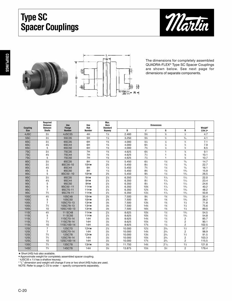
TypeSCSpacerCouplings
The dimensions for completely assembledQUADRA-FLEX® Type SC Spacer Couplingsare shown below. See next page fordimensions of separate components.
4JSC 31⁄2 4JSC35 4H 11⁄8 2.460 55⁄8 5⁄8 1⁄2 4.75SC 31⁄2 5SC35 5H 11⁄8 3.250 55⁄8 3⁄4 9⁄16 4.16SC 31⁄2 6SC35 6H 13⁄8 4.000 57⁄8 7⁄8 3⁄4 7.16SC 43⁄8 6SC44 6H 13⁄8 4.000 63⁄4 7⁄8 3⁄4 7.96SC 5 6SC50 6H 13⁄8 4.000 73⁄8 7⁄8 3⁄4 8.57SC 31⁄2 7SC35 7H 15⁄8 4.625 63⁄8 1 5⁄8 9.17SC 43⁄8 7SC44 7H 15⁄8 4.625 71⁄4 1 5⁄8 10.17SC 5 7SC50 7H 15⁄8 4.625 77⁄8 1 5⁄8 10.78SC 31⁄2 8SC35 8H 17⁄8 5.450 67⁄8 11⁄8 13⁄16 14.78SC 31⁄2 8SC35-10 10H� 23⁄8 5.450 81⁄8 11⁄8 13⁄16 22.78SC 43⁄8 8SC44 8H 17⁄8 5.450 73⁄4 11⁄8 13⁄16 16.18SC 5 8SC50 8H 17⁄8 5.450 83⁄8 11⁄8 13⁄16 15.98SC 5 8SC50 -10 10H� 23⁄8 5.450 95⁄8 11⁄8 13⁄16 26.59SC 31⁄2 9SC35 9H� 21⁄8 6.350 71⁄2 17⁄16 11⁄16 22.09SC 43⁄8 9SC44 9H� 21⁄8 6.350 81⁄4 17⁄16 11⁄16 23.49SC 5 9SC50 9H� 21⁄8 6.350 87⁄8 17⁄16 11⁄16 24.69SC 5 9SC50 -11 11H� 27⁄8 6.350 103⁄8 17⁄16 13⁄16 40.29SC 7 9SC70-11 11H� 27⁄8 6.350 123⁄8 17⁄16 13⁄16 48.29SC 73⁄4 9SC78-11 11H� 27⁄8 6.350 131⁄8 17⁄16 13⁄16 50.810SC 43⁄4 10SC48 10H� 23⁄8 7.500 93⁄8 15⁄8 13⁄16 35.410SC 5 10SC50 10H� 23⁄8 7.500 95⁄8 15⁄8 13⁄16 38.210SC 7 10SC70-13 13H� 33⁄8 7.500 135⁄8 15⁄8 17⁄8 71.810SC 73⁄4 10SC78-13 13H� 33⁄8 7.500 143⁄8 15⁄8 17⁄8 75.610SC 10 10SC100-13 13H� 33⁄8 7.500 165⁄8 15⁄8 17⁄8 89.011SC 43⁄4 11 SC48 11H� 27⁄8 8.625 105⁄8 17⁄8 13⁄16 54.511SC 5 11 SC50 11H� 27⁄8 8.625 103⁄8 17⁄8 13⁄16 54.811SC 7 11SC70-14 14H 37⁄8 8.625 145⁄8 17⁄8 2 85.711SC 73⁄4 11SC78-14 14H 37⁄8 8.625 153⁄8 17⁄8 2 90.111SC 10 11SC100-14 14H 37⁄8 8.625 175⁄8 17⁄8 2 102.512SC 7 12SC70 12H� 27⁄8 10.000 127⁄8 25⁄16 11⁄2 87.712SC 7 12SC70-14 14H 37⁄8 10.000 145⁄8 25⁄16 2 98.912SC 73⁄4 12SC78 12H� 27⁄8 10.000 135⁄8 25⁄16 11⁄2 91.512SC 73⁄4 12SC78-14 14H 37⁄8 10.000 153⁄8 25⁄16 2 103.312SC 10 12SC100-14 14H 37⁄8 10.000 175⁄8 25⁄16 2 115.513SC 73⁄4 13SC78 13H� 33⁄8 11.750 143⁄8 211⁄16 17⁄8 121.814SC 73⁄4 14SC78 14H 37⁄8 13.875 153⁄8 31⁄4 2 179.4
Required Max.Distance Use Use Bore Dimensions
Coupling Between Flange Hub Standard Weight2Size Shafts Number Number Keyway D L2 G R (Lbs.)•
� Short (HS) hub also available.• Approximate weight for completely assembled spacer coupling.1 4JSC35 x 11⁄8 has a shallow keyway.2 “L” dimension and weight will change if one or two short (HS) hubs are used.NOTE: Refer to page C-23 to order — specify components separately.

C-21
COUP
LING
S
TypeSCFlangesandHubs
Tables below provide dimensionalinformation for QUADRA-FLEX® Flangesand Hubs used for Spacer Couplings.Assembled dimensions are listed onopposite page. Any of the sleeves shownon page C-14 can be used.
TypeSCFlangesandHubs
� Flanges can be mixed to form different Between-Shaft Dimensions. See chart on page 23.• Approximate weight for each flange.
4JSC 4SC35 31⁄2 4H 2.460 7⁄16 2 7⁄8 7⁄16 1.25SC 5SC35 31⁄2 5H 3.250 51⁄64 2 111⁄16 19⁄32 1.2
6SC35 31⁄2 6H 4.000 19⁄32 21⁄2 15⁄8 23⁄32 2.06SC 6SC44 43⁄8 6H 4.000 11⁄32 21⁄2 21⁄16 23⁄32 2.4
6SC50 5 6H 4.000 111⁄32 21⁄2 23⁄8 23⁄32 2.77SC35 31⁄2 7H 4.625 15⁄32 213⁄16 15⁄8 25⁄32 2.3
7SC 7SC44 43⁄8 7H 4.625 29⁄32 213⁄16 21⁄16 25⁄32 2.87SC50 5 7H 4.625 17⁄32 213⁄16 23⁄8 25⁄32 3.18SC35 31⁄2 8H 5.450 9⁄32 31⁄4 15⁄8 29⁄32 3.5
8SC35-10 31⁄2 10H-10HS 5.450 9⁄32 43⁄8 15⁄8 29⁄32 3.48SC 8SC44 43⁄8 8H 5.450 23⁄32 31⁄24 21⁄16 29⁄32 4.2
8SC50 5 8H 5.450 11⁄32 31⁄4 23⁄8 29⁄32 4.68SC50-10 5 10H-10HS 5.450 11⁄32 43⁄8 23⁄8 29⁄32 5.39SC35 31⁄2 9H-9HS 6.350 1⁄16 35⁄8 111⁄16 11⁄32 5.19SC44 43⁄8 9H-9HS 6.350 7⁄16 35⁄8 21⁄16 11⁄32 5.8
9SC 9SC50 5 9H-9HS 6.350 3⁄4 35⁄8 23⁄8 11⁄32 6.49SC50-11 5 11H-11HS 6.350 3⁄4 51⁄4 23⁄8 11⁄32 6.99SC70-11 7 11H-11HS 6.350 13⁄4 51⁄4 33⁄8 11⁄32 10.99SC78-11 73⁄4 11H-11HS 6.350 21⁄8 51⁄4 33⁄4 11⁄32 12.110SC48 43⁄4 10H-10HS 7.500 11⁄32 43⁄8 21⁄4 17⁄32 9.810SC50 5 10H-10HS 7.500 15⁄32 43⁄8 23⁄8 17⁄32 10.1
10SC 10SC70-13 7 13H-13HS 7.500 115⁄32 61⁄8 33⁄8 17⁄32 14.510SC78-13 73⁄4 13H-13HS 7.500 127⁄32 61⁄8 33⁄4 17⁄32 16.310SC100-13 10 13H-13HS 7.500 231⁄32 61⁄8 47⁄8 17⁄32 22.511SC48 43⁄4 11H-11HS 8.625 1⁄32 51⁄4 11⁄2 11⁄2 12.511SC50 5 11H11HS 8.625 1⁄16 51⁄4 19⁄16 11⁄2 12.7
11SC 11SC70-14 7 14H 8.625 11⁄16 61⁄2 29⁄16 11⁄2 16.111SC78-14 73⁄4 14H 8.625 17⁄16 61⁄2 215⁄16 11⁄2 18.311SC100-14 10 14H 8.625 29⁄16 61⁄2 41⁄16 11⁄2 24.512SC70 7 12H-12HS 10.000 21⁄32 53⁄4 215⁄32 111⁄16 23.2
12SC70-14 7 14H 10.000 21⁄32 61⁄2 215⁄32 111⁄16 21.212SC 12SC78 73⁄4 12H-12HS 10.000 11⁄32 53⁄4 227⁄32 111⁄16 25.1
12SC78-14 73⁄4 14H 10.000 11⁄32 61⁄2 227⁄32 111⁄16 23.412SC100-14 10 14H 10.000 25⁄32 61⁄2 331⁄32 111⁄16 29.5
13SC 13SC78 73⁄4 13H-13HS 11.750 9⁄16 61⁄8 31⁄4 131⁄32 38.414SC 14SC78 73⁄4 14H 13.875 1⁄32 61⁄2 223⁄32 21⁄4 55.0
For Distance DimensionsCoupling Flange Between For WeightSize Number Shafts� Hub D E H C T (Lbs.)•
C-22
COUPLINGS
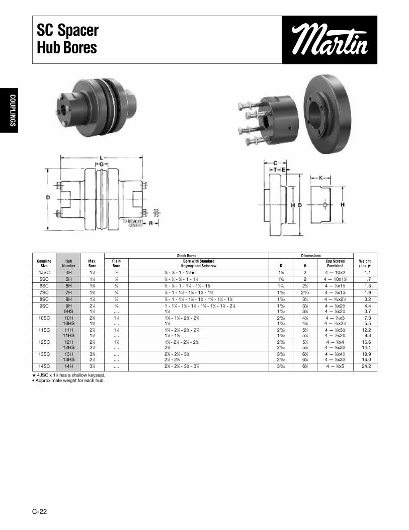
SC SpacerHubBores
� 4JSC x 11⁄8 has a shallow keyseat.• Approximate weight for each hub.
4JSC 4H 11⁄8 1⁄2 5⁄8 - 7⁄8 - 1 - 11⁄8� 15⁄8 2 4 — 10x2 1.15SC 5H 11⁄8 1⁄2 5⁄8 - 3⁄4 - 7⁄8 - 1 - 11⁄8 13⁄32 2 4 — 10x11⁄2 .76SC 6H 13⁄8 5⁄8 3⁄4 - 7⁄8 - 1 - 11⁄8 - 11⁄4 - 13⁄8 17⁄32 21⁄2 4 — 1⁄4x13⁄4 1.37SC 7H 15⁄8 5⁄8 7⁄8 - 1 - 11⁄8 - 13⁄8 - 11⁄2 - 15⁄8 115⁄32 213⁄16 4 — 1⁄4x17⁄8 1.98SC 8H 17⁄8 3⁄4 7⁄8 - 1 - 11⁄8 - 13⁄8 - 11⁄2 - 15⁄8 - 13⁄4 - 17⁄8 123⁄32 31⁄4 4 — 5⁄16x21⁄4 3.29SC 9H 21⁄8 7⁄8 1 - 11⁄8 - 13⁄8 - 11⁄2 - 15⁄8 - 13⁄4 - 17⁄8 - 21⁄8 131⁄32 35⁄8 4 — 3⁄8x23⁄4 4.4
9HS 11⁄2 .... 11⁄8 117⁄32 35⁄8 4 — 3⁄8x21⁄4 3.710SC 10H 23⁄8 11⁄8 15⁄8 - 17⁄8 - 21⁄8 - 23⁄8 211⁄32 43⁄8 4 — 7⁄16x3 7.3
10HS 15⁄8 .... 11⁄8 121⁄32 43⁄8 4 — 7⁄16x21⁄2 5.511SC 11H 27⁄8 11⁄8 17⁄8 - 21⁄8 - 23⁄8 - 27⁄8 223⁄32 51⁄4 4 — 1⁄2x31⁄2 12.2
11HS 17⁄8 .... 11⁄8 - 15⁄8 129⁄32 51⁄4 4 — 1⁄2x23⁄4 9.312SC 12H 27⁄8 17⁄8 17⁄8 - 21⁄8 - 23⁄8 - 27⁄8 231⁄32 53⁄4 4 — 5⁄8x4 16.6
12HS 21⁄2 .... 23⁄8 217⁄32 53⁄4 4 — 5⁄8x31⁄2 14.113SC 13H 33⁄8 .... 23⁄8 - 27⁄8 - 33⁄8 311⁄32 61⁄8 4 — 5⁄8x43⁄4 19.9
13HS 21⁄2 .... 21⁄8 - 23⁄8 215⁄32 61⁄8 4 — 5⁄8x31⁄2 16.014SC 14H 37⁄8 .... 23⁄8 - 27⁄8 - 33⁄8 - 37⁄8 327⁄32 61⁄2 4 — 5⁄8x5 24.2
Stock Bores DimensionsCoupling Hub Max. Plain Bore with Standard Cap Screws WeightSize Number Bore Bore Keyway and Setscrew K H Furnished (Lbs.)•
C-23
COUP
LING
S
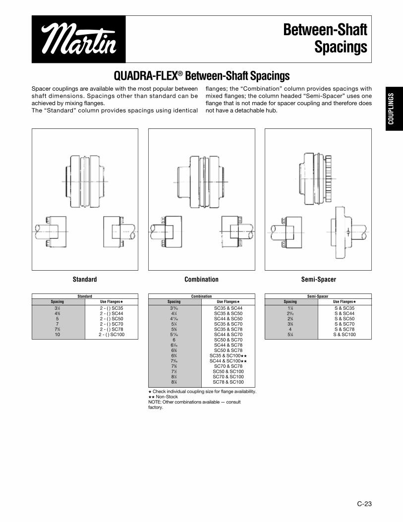
Between-ShaftSpacings
QUADRA-FLEX® Between-Shaft SpacingsSpacer couplings are available with the most popular betweenshaft dimensions. Spacings other than standard can beachieved by mixing flanges.The “Standard” column provides spacings using identical
flanges; the “Combination” column provides spacings withmixed flanges; the column headed “Semi-Spacer” uses oneflange that is not made for spacer coupling and therefore doesnot have a detachable hub.
� Check individual coupling size for flange availability.�� Non-StockNOTE: Other combinations available — consultfactory.
Standard Combination Semi-Spacer
31⁄2 2 - ( ) SC3543⁄8 2 - ( ) SC445 2 - ( ) SC507 2 - ( ) SC7073⁄4 2 - ( ) SC7810 2 - ( ) SC100
StandardSpacing Use Flanges�
17⁄8 S & SC3525⁄16 S & SC4425⁄8 S & SC5035⁄8 S & SC704 S & SC7851⁄8 S & SC100
Semi-SpacerSpacing Use Flanges�
315⁄16 SC35 & SC4441⁄4 SC35 & SC50411⁄16 SC44 & SC5051⁄4 SC35 & SC7055⁄8 SC35 & SC78511⁄16 SC44 & SC706 SC50 & SC7061⁄16 SC44 & SC7863⁄8 SC50 & SC7863⁄4 SC35 & SC100��
73⁄16 SC44 & SC100��
73⁄8 SC70 & SC7871⁄2 SC50 & SC10081⁄2 SC70 & SC10087⁄8 SC78 & SC100
CombinationSpacing Use Flanges�

C-24
COUPLINGS
InstallationInstructions
Martin QUADRA-FLEX® flanges (hubs) and elastomericelements (sleeves) come in a wide range of sizes and types.First, determine the size and type of coupling componentsrequired. Remove all components from their boxes and looselyassemble the coupling. Do not install the wire ring on the twopiece sleeves at this time. Check maximum RPM values intable against operating speeds.Martin EM sleeves are rated the same as other EPDM andNeoprene sleeves, and may be used interchangeably; however,Hytrel sleeves are rated at different values and may not beinterchanged with Martin EM sleeves, or the EPDM andNeoprene sleeves. Check horsepower and torque ratings whenselecting Hytrel sleeves.
Step 1. Make sure the motor driving the part or components islocked out electrically in such a manner that it cannot be startedby anyone, however remote from the area. The same type oflockout procedure applies to any other driving device whichmay be used. Failure to follow these instructions may result inpersonal injury or property damage.Step 2. Prepare shafts for coupling installation. Inspect allcoupling components and remove any protective coating orlubricants from bores, mating surfaces, and fasteners.Step 3. Slide one coupling flange onto each prepared shaftusing key stock where required. With the QD Type B flange, itmay be necessary to expand the QD bushing bore for ease ofinstallation.Step 4. Position the flange on the shafts to acheive theapproximate “Y” dimension (distance between flanges) shownin table. It is best to have equal shaft length into each flange.Tighten one flange in position, and slide the other flangesufficient distance back to install sleeve. Do not install wire ringon two piece sleeve in its final position at this time, but allow itto hang loosely in groove next to teeth.
Step 5. Slide loose flange on the shaft until the sleeve hasseated completely in teeth of both flanges. Refer to “Y”dimension although not a critical dimension. Secure the flangeto shaft and torque set screws and cap screws to correcttorque values.
Step 6. Check parallel alignment by placing a straight edgeacross the two coupling flanges and measure the maximumoffset at several points around the periphery of coupling. Donot rotate coupling when taking these measurements. Refer totable for maximum allowed offset of parallel alignment. Realignthe coupling if necessary.Step 7. Check angular alignment with a micrometer, vernier, orcaliper. Take measurement from outside to outside of flanges atseveral points around the periphery of coupling. Do not rotatecoupling when taking these measurements. Determine thedifference between maximum and minimum dimensions andcheck to make sure they do not exceed the angluar figure on thetable. If a correction is necessary, recheck parallel alignment.
NOTE: Values shown above may apply if the actual torque transmitted is more than1⁄4 the coupling rating. For lesser torque, reduce the above values by 1⁄2.� Type H & HS sleeves should not be used as direct replacements for JEM or EMsleeves.† Value when using 6J flanges is 2.125.
Step 8. If the coupling employs the two-piece sleeve with wirering, install ring in center groove of sleeve.Note: Some force may be required to seat the ring in groove.Step 9. Install protective guards and/or shields per OSHA andany other additional local or state safety codes as required.
WARNING: Coupling sleeves may be forced from couplingwhen subjected to a severe shock load or abuse.
MaximumRPMandAllowableMisalignment(Dimensions in Inches)
3 9200 .010 .035 1.188 — — —4 7600 .010 .043 1.500 — — —5 7600 .015 .056 1.938 — — —6 6000 .015 .070 2.438† .010 .016 2.5007 5250 .020 .081 2.563 .012 .020 2.6258 4500 .020 .094 2.938 .015 .025 3.0009 3750 .025 .109 3.500 .017 .028 3.56310 3600 .025 .128 4.053 .020 .032 4.12511 3600 .032 .151 4.875 .022 .037 4.93812 2800 .032 .175 5.688 .025 .042 5.75013 2400 .040 .195 6.688 .030 .050 6.68814 2200 .045 .242 7.750 .035 .060 7.81316 1500 .062 .330 10.250 — — —
Sleeve Max. Types JEM, EM, E and N �Type H & HSSize RPM Parallel Angular Y Parallel Angular Y
Parallel Angular
C-25
COUP
LING
S
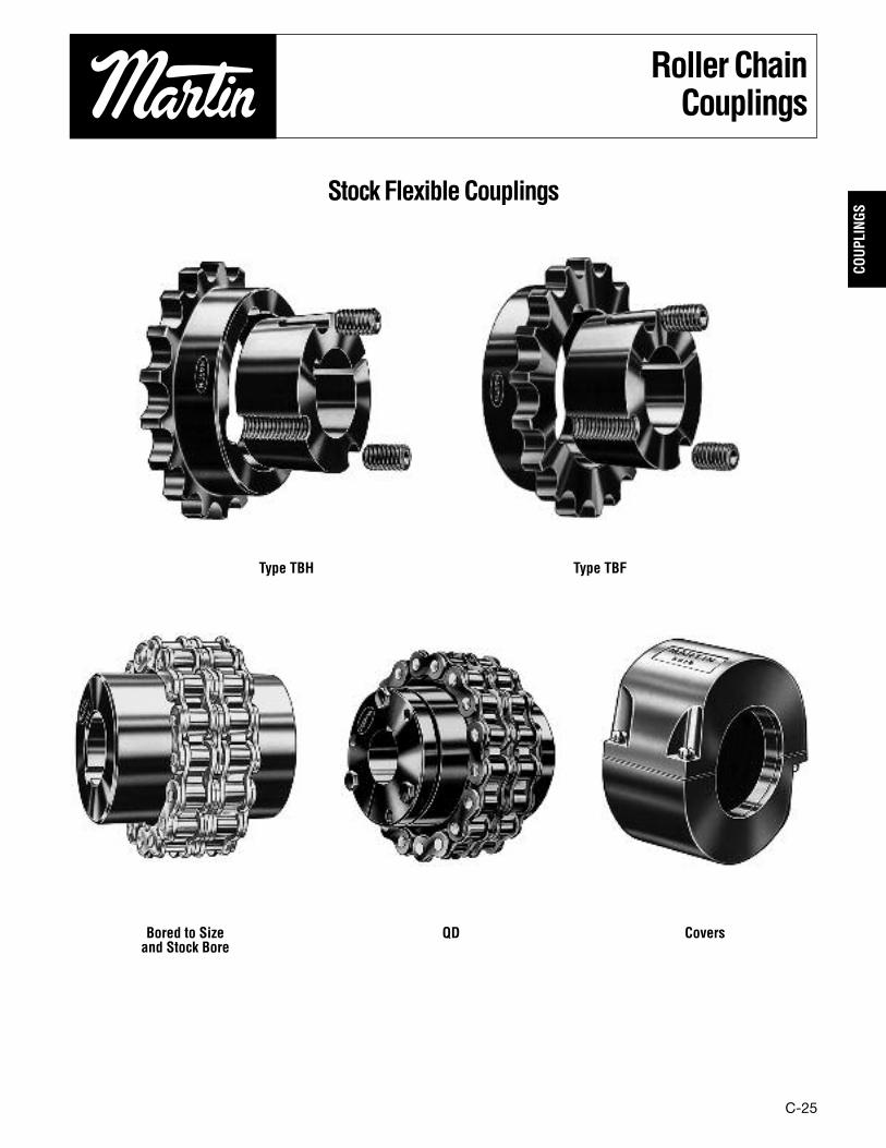
RollerChainCouplings
StockFlexibleCouplings
Type TBH Type TBF
Bored to Sizeand Stock Bore
QD Covers
C-26
COUPLINGS
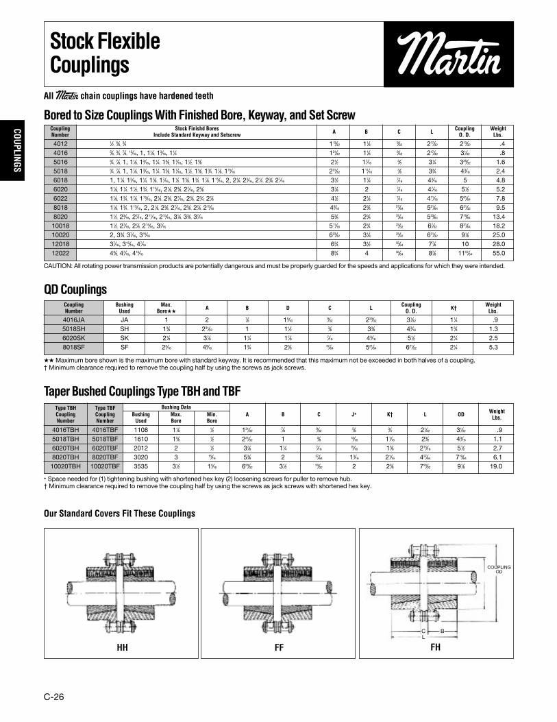
StockFlexibleCouplings
Bored toSizeCouplingsWithFinishedBore,Keyway, andSetScrew
QDCouplings
TaperBushedCouplingsTypeTBHandTBF
CAUTION: All rotating power transmission products are potentially dangerous and must be properly guarded for the speeds and applications for which they were intended.
�� Maximum bore shown is the maximum bore with standard keyway. It is recommended that this maximum not be exceeded in both halves of a coupling.† Minimum clearance required to remove the coupling half by using the screws as jack screws.
� Space needed for (1) tightening bushing with shortened hex key (2) loosening screws for puller to remove hub.† Minimum clearance required to remove the coupling half by using the screws as jack screws with shortened hex key.
Our Standard Covers Fit These Couplings
HH FF FH
4012 1⁄2, 5⁄8, 3⁄4 113⁄32 11⁄8 9⁄32 217⁄32 213⁄32 .44016 5⁄8, 3⁄4, 7⁄8, 15⁄16, 1, 11⁄8, 13⁄16, 11⁄4 131⁄32 11⁄8 9⁄32 217⁄32 31⁄32 .85016 3⁄4, 7⁄8, 1, 11⁄8, 13⁄16, 11⁄4, 13⁄8, 17⁄16, 11⁄2, 15⁄8 21⁄2 17⁄16 3⁄8 31⁄4 325⁄32 1.65018 3⁄4, 7⁄8, 1, 11⁄8, 13⁄16, 11⁄4, 13⁄8, 17⁄16, 11⁄2, 15⁄8, 13⁄4, 17⁄8, 115⁄16 231⁄32 111⁄16 3⁄8 33⁄4 43⁄16 2.46018 1, 11⁄8, 13⁄16, 11⁄4, 13⁄8, 17⁄16, 11⁄2, 15⁄8, 13⁄4, 17⁄8, 115⁄16, 2, 21⁄8, 23⁄16, 21⁄4, 23⁄8, 27⁄16 31⁄2 17⁄8 7⁄16 43⁄16 5 4.86020 11⁄8, 11⁄4, 11⁄2, 13⁄4, 115⁄16, 21⁄8, 23⁄8, 27⁄16, 25⁄8 37⁄8 2 7⁄16 47⁄16 51⁄2 5.26022 11⁄8, 13⁄4, 17⁄8, 115⁄16, 21⁄8, 23⁄8, 27⁄16, 25⁄8, 23⁄4, 27⁄8 41⁄2 21⁄8 7⁄16 411⁄16 561⁄64 7.88018 11⁄8, 13⁄4, 115⁄16, 2, 21⁄8, 23⁄8, 27⁄16, 25⁄8, 27⁄8, 215⁄16 49⁄16 23⁄8 37⁄64 521⁄64 621⁄32 9.58020 11⁄2, 23⁄16, 27⁄16, 211⁄16, 215⁄16, 31⁄8, 33⁄8, 37⁄16 53⁄8 25⁄8 37⁄64 533⁄64 719⁄64 13.410018 11⁄2, 27⁄16, 27⁄8, 215⁄16, 37⁄16 511⁄16 23⁄4 23⁄32 67⁄32 821⁄64 18.210020 2, 33⁄8, 37⁄16, 315⁄16 623⁄32 31⁄8 23⁄32 631⁄32 91⁄8 25.012018 37⁄16, 315⁄16, 47⁄16 63⁄4 31⁄2 55⁄64 77⁄8 10 28.012022 43⁄8, 47⁄16, 415⁄16 83⁄4 4 55⁄64 87⁄8 1157⁄64 55.0
4016JA JA 1 2 7⁄8 15⁄16 9⁄32 229⁄32 31⁄32 11⁄4 .95018SH SH 13⁄8 231⁄32 1 11⁄2 3⁄8 33⁄8 43⁄16 13⁄4 1.36020SK SK 21⁄8 37⁄8 11⁄4 17⁄8 7⁄16 43⁄16 51⁄2 21⁄4 2.58018SF SF 25⁄16 49⁄16 13⁄4 23⁄8 37⁄64 521⁄64 621⁄32 21⁄4 5.3
Coupling Stock Finishd Bores Coupling WeightNumber Include Standard Keyway and Setscrew A B C L O. D. Lbs.
Coupling Bushing Max. Coupling WeightNumber Used Bore��
A B D C L O. D. K† Lbs.
4016TBH 4016TBF 1108 11⁄8 1⁄2 131⁄32 7⁄8 9⁄32 5⁄8 3⁄4 21⁄32 31⁄32 .95018TBH 5018TBF 1610 15⁄8 1⁄2 231⁄32 1 3⁄8 13⁄16 11⁄16 23⁄8 43⁄16 1.16020TBH 6020TBF 2012 2 1⁄2 37⁄8 11⁄4 7⁄16 15⁄16 13⁄8 215⁄16 51⁄2 2.78020TBH 8020TBF 3020 3 15⁄16 53⁄8 2 37⁄64 13⁄16 21⁄16 437⁄64 719⁄64 6.110020TBH 10020TBF 3535 31⁄2 13⁄16 623⁄32 31⁄2 23⁄32 2 25⁄8 723⁄32 91⁄8 19.0
Type TBH Type TBF Bushing DataCoupling Coupling Bushing Max. Min. A B C J� K† L OD Weight
Number Number Used Bore Bore Lbs.
C B
COUPLINGOD
L
All Martin chain couplings have hardened teeth

C-27
COUP
LING
S
StockFlexibleCouplings
Roller chain couplings have a torque capacity in excess of the torque normallytransmitted by shafting which falls within the coupling bore range. Select the smallestcoupling which will accomodate both shafts. For a reversing operation, shock orpulsating loads, or other severe operating conditions, select the next larger couplingsize.
A cover should be used to assure maximum service life, particularly if the couplingoperates at high speeds or under moist conditions. For proper lubrication, fill the spacebetween the cover and the coupling with soft to medium consistency coupling grease.
CouplingWithPlainBores forReboring
Covers Fit Taper Bushed, QD and Stock, and Finished Bore Couplings. Covers allowexcellent lubrication, and their use is recommended to obtain maximum coupling life.Covers are of aluminum and are made in halves for easy installation. Synthetic rubberoil seals, which contact the coupling hubs, retain the lubricant and prevent the entry ofdirt. Covers are fitted with gaskets between the halves.
All Martin chain couplings have hardened teeth
Type TBF
Type TBH
* Use 8018 cover — Special Seals Available** Furnished in Plastic unless specified with “AL”Suffix when ordering.
CouplingSelection
4012 7⁄8 7⁄16 .5 5000 4012 CHN .44016 15⁄16 5⁄8 1.0 5000 4016 CHN .55016 111⁄16 5⁄8 2.2 4000 5016 CHN 1.25018 2 3⁄4 3.5 3600 5018 CHN 1.36018 27⁄16 1 5.0 3000 6018 CHN 2.26020 23⁄4 11⁄8 6.5 2500 6020 CHN 2.66022 3 11⁄8 9.4 2500 6022 CHN 2.78018 31⁄8 11⁄8 11.0 2000 8018 CHN 5.38020 39⁄16 11⁄2 16.3 2000 8020 CHN 5.910018 37⁄8 11⁄2 20.3 1800 10018 CHN 9.810020 45⁄8 11⁄2 31.8 1800 10020 CHN 10.912018 411⁄16 2 36.8 1500 12018 CHN 17.312022 61⁄8 2 70.0 1200 12022 CHN 21.2
4012COV** 4 2 4 25⁄16 .784016COV** 4 2 4 25⁄16 .925016COV** 51⁄8 23⁄8 51⁄8 25⁄8 1.305018COV** 51⁄8 23⁄8 51⁄8 25⁄8 1.306018COV** 63⁄8 215⁄16 63⁄8 31⁄16 2.446020COV** 63⁄8 215⁄16 63⁄8 31⁄16 2.446022COV* 83⁄16 4 83⁄16 4 4.888018COV 83⁄16 4 83⁄16 4 4.888020COV 83⁄16 4 83⁄16 4 4.8810018COV 93⁄8 515⁄16 93⁄8 515⁄16 8.7610020COV 101⁄8 51⁄4 101⁄8 51⁄4 12.6612018COV 113⁄8 73⁄8 113⁄8 73⁄8 16.4612022COV 131⁄4 715⁄16 131⁄4 715⁄16 19.50
Maximum Minimum CouplingCoupling Bore Plain Bore Weight Recommended Chain WeightNumber Inches Inches (Lbs.) Maximum RPM Number Lbs.
QD Coupling
StockCouplingCovers
Cover Aluminum Plastic Wt.Cat. No. D W D W Lbs.
Aluminumand
Plastic
CouplingOD
CouplingODA
C BL
BS Coupling
C-28
COUPLINGS
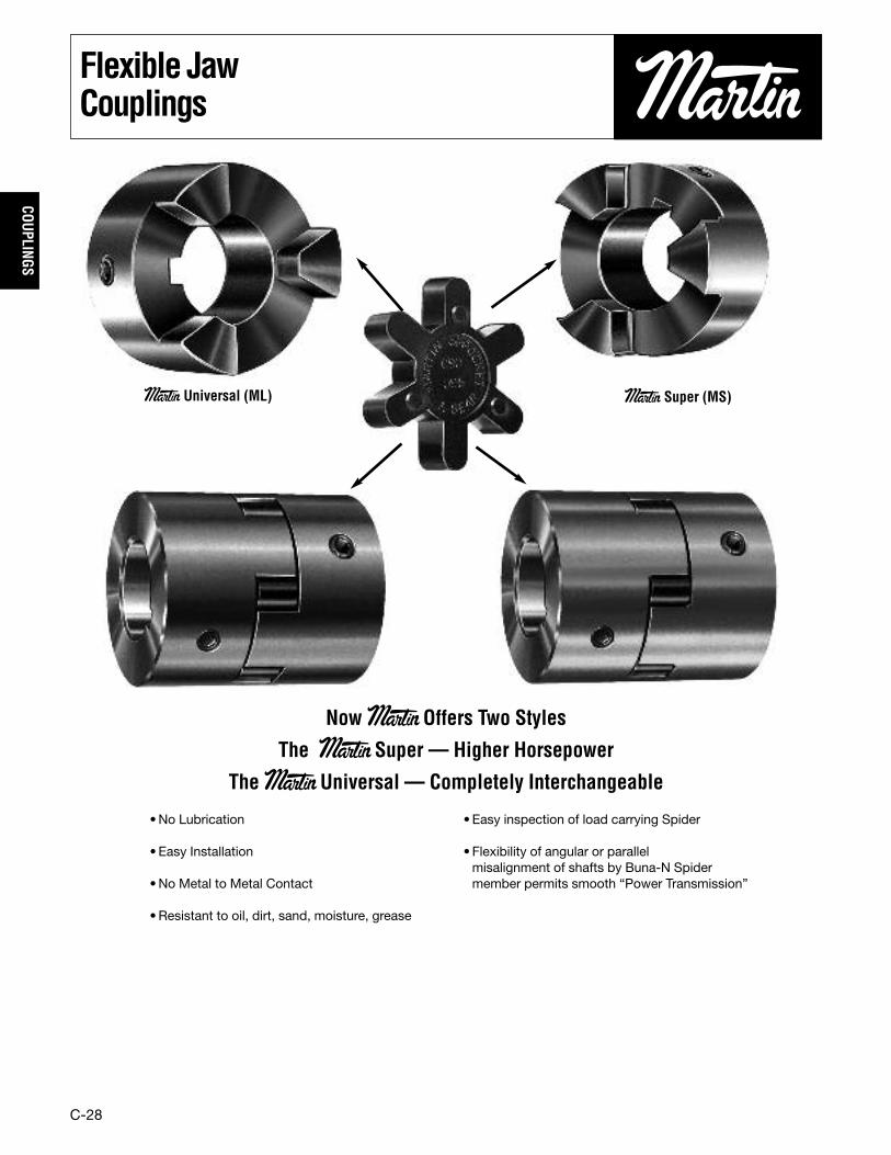
Flexible JawCouplings
Now MartinOffers Two Styles
The Martin Super — Higher Horsepower
The MartinUniversal — Completely Interchangeable
Martin Universal (ML) Martin Super (MS)
•No Lubrication
• Easy Installation
•No Metal to Metal Contact
•Resistant to oil, dirt, sand, moisture, grease
•Easy inspection of load carrying Spider
• Flexibility of angular or parallelmisalignment of shafts by Buna-N Spidermember permits smooth “Power Transmission”
C-29
COUP
LING
S
Stock JawCouplings
MS050 37.3 112 .06 .18 .71 1.0 2.1 5⁄8 .13MS070 59.4 178 .09 .28 1.1 1.7 3.4 3⁄4 .25MS075 157 471 .25 .75 3.0 4.5 8.9 7⁄8 .44MS090 241 723 .38 1.1 4.6 6.9 13.7 11⁄8 .69MS095 241 723 .38 1.1 4.6 6.9 13.7 11⁄8 .84MS099 512 1536 .81 2.4 9.7 14.6 29.2 13⁄8 1.19MS100 512 1536 .81 2.4 9.7 14.6 29.2 13⁄8 1.47MS110 1014 3042 1.6 4.8 19.3 28.9 57.8 15⁄8 3.20MS150 1630 4890 2.6 7.7 31.0 46.5 93.0 17⁄8 4.50MS190 2450 7350 3.9 11.6 46.6 69.9 139.7 21⁄8 8.25MS225 2920 8760 4.6 13.9 55.5 83.2 166.5 25⁄8 12.00
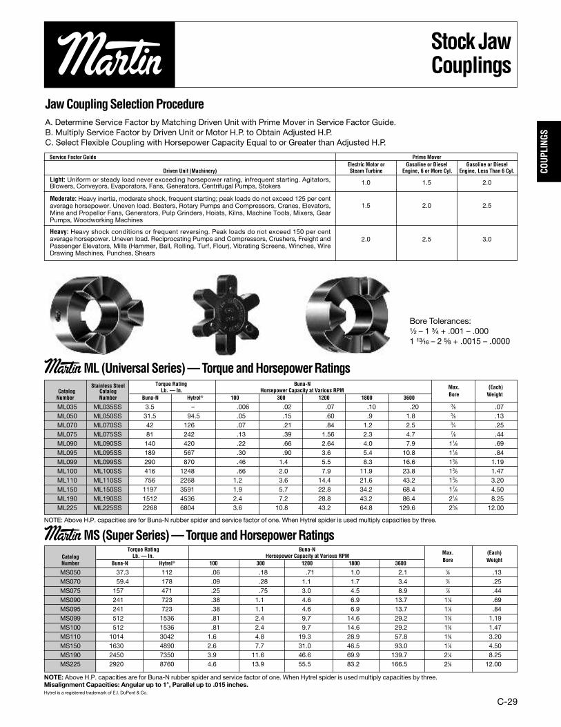
JawCouplingSelectionProcedureA. Determine Service Factor by Matching Driven Unit with Prime Mover in Service Factor Guide.B. Multiply Service Factor by Driven Unit or Motor H.P. to Obtain Adjusted H.P.C. Select Flexible Coupling with Horsepower Capacity Equal to or Greater than Adjusted H.P.
Service Factor Guide Prime MoverElectric Motor or Gasoline or Diesel Gasoline or Diesel
Driven Unit (Machinery) Steam Turbine Engine, 6 or More Cyl. Engine, Less Than 6 Cyl.
1.0 1.5 2.0
1.5 2.0 2.5
2.0 2.5 3.0
NOTE: Above H.P. capacities are for Buna-N rubber spider and service factor of one. When Hytrel spider is used multiply capacities by three.
NOTE: Above H.P. capacities are for Buna-N rubber spider and service factor of one. When Hytrel spider is used multiply capacities by three.Misalignment Capacities: Angular up to 1°, Parallel up to .015 inches.Hytrel is a registered trademark of E.I. DuPont & Co.
Light: Uniform or steady load never exceeding horsepower rating, infrequent starting. Agitators,Blowers, Conveyors, Evaporators, Fans, Generators, Centrifugal Pumps, Stokers
Moderate: Heavy inertia, moderate shock, frequent starting; peak loads do not exceed 125 per centaverage horsepower. Uneven load. Beaters, Rotary Pumps and Compressors, Cranes, Elevators,Mine and Propellor Fans, Generators, Pulp Grinders, Hoists, Kilns, Machine Tools, Mixers, GearPumps, Woodworking Machines
Heavy: Heavy shock conditions or frequent reversing. Peak loads do not exceed 150 per centaverage horsepower. Uneven load. Reciprocating Pumps and Compressors, Crushers, Freight andPassenger Elevators, Mills (Hammer, Ball, Rolling, Turf, Flour), Vibrating Screens, Winches, WireDrawing Machines, Punches, Shears
Torque Rating Buna-NCatalog Lb. — In. Horsepower Capacity at Various RPM Max. (Each)
Number Buna-N Hytrel® 100 300 1200 1800 3600 Bore Weight
MartinMS(SuperSeries)—TorqueandHorsepowerRatings
MartinML(UniversalSeries)—TorqueandHorsepowerRatings
Bore Tolerances:¹⁄₂ – 1 ³⁄₄ + .001 – .0001 ¹³⁄₁₆ – 2 ⁵⁄₈ + .0015 – .0000
Stainless Steel Torque Rating Buna-NCatalog Catalog Lb. — In. Horsepower Capacity at Various RPM Max. (Each)
Number Number Buna-N Hytrel® 100 300 1200 1800 3600 Bore Weight
ML035 ML035SS 3.5 – .006 .02 .07 .10 .20 3⁄8 .07ML050 ML050SS 31.5 94.5 .05 .15 .60 .9 1.8 5⁄8 .13ML070 ML070SS 42 126 .07 .21 .84 1.2 2.5 3⁄4 .25ML075 ML075SS 81 242 .13 .39 1.56 2.3 4.7 7⁄8 .44ML090 ML090SS 140 420 .22 .66 2.64 4.0 7.9 11⁄8 .69ML095 ML095SS 189 567 .30 .90 3.6 5.4 10.8 11⁄8 .84ML099 ML099SS 290 870 .46 1.4 5.5 8.3 16.6 13⁄8 1.19ML100 ML100SS 416 1248 .66 2.0 7.9 11.9 23.8 13⁄8 1.47ML110 ML110SS 756 2268 1.2 3.6 14.4 21.6 43.2 15⁄8 3.20ML150 ML150SS 1197 3591 1.9 5.7 22.8 34.2 68.4 17⁄8 4.50ML190 ML190SS 1512 4536 2.4 7.2 28.8 43.2 86.4 21⁄8 8.25ML225 ML225SS 2268 6804 3.6 10.8 43.2 64.8 129.6 25⁄8 12.00
SUL035 SBL035 ML 035 .009 0.05SUL050 SBL050 ML050 — MS050 .013 0.08SUL070 SBL070 ML070 — MS070 .017 0.06SUL075 SBL075 ML075 — MS075 .03 0.15SUL090/ SBL090/
ML or MS 090-095 .04 0.17095 095SUL099/ SBL099/ ML or MS 099-100 .07 0.50100 100SUL110 SBL110 ML110 — MS110 .14 0.62SUL150 SBL150 ML150 — MS150 .21 1.00SUL190 SBL190 ML190 — MS190 .27 1.30SUL225 SBL225 ML225 — MS225 .41 1.60
C-30
COUPLINGS
Stock JawCouplings
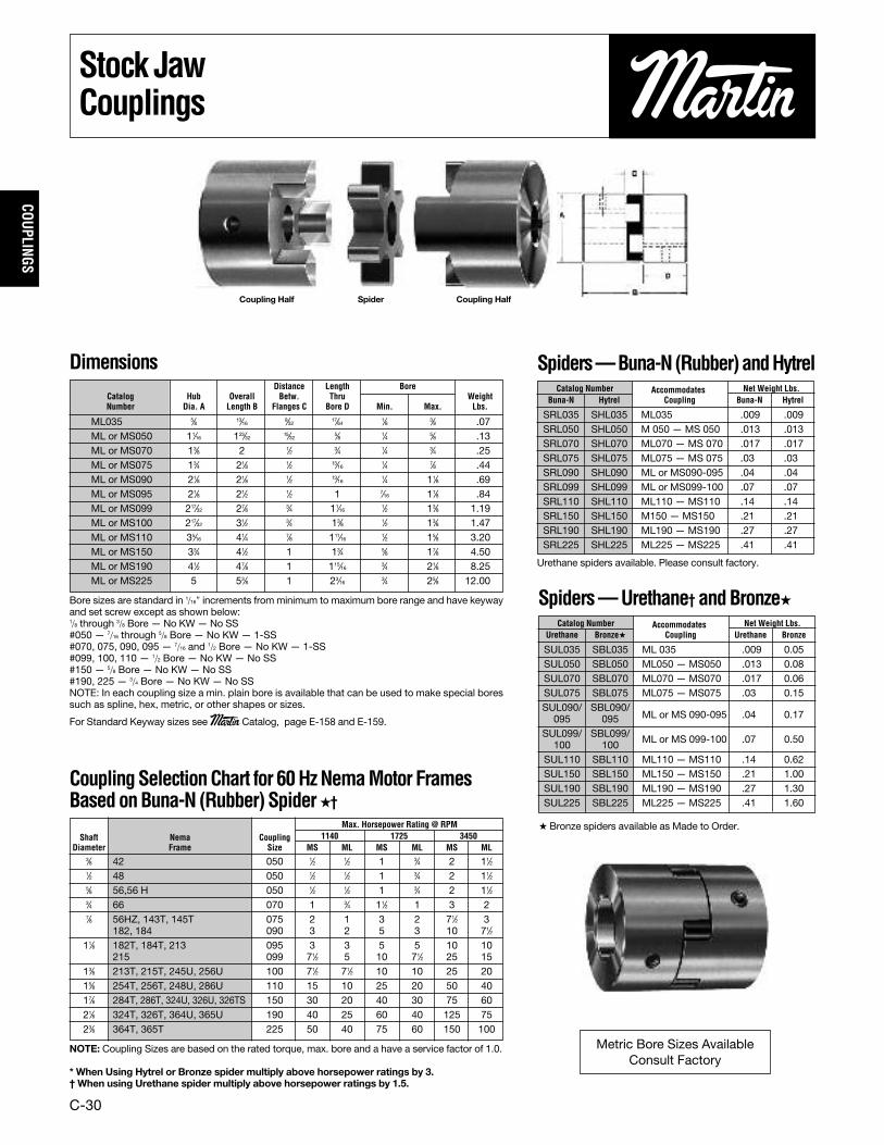
Bore sizes are standard in 1/16″ increments from minimum to maximum bore range and have keywayand set screw except as shown below:1/8 through 3/8 Bore — No KW—No SS#050 — 7/16 through 5/8 Bore — No KW— 1-SS#070, 075, 090, 095 — 7/16 and 1/2 Bore — No KW— 1-SS#099, 100, 110 — 1/2 Bore — No KW— No SS#150 — 5/8 Bore — No KW— No SS#190, 225 — 3/4 Bore — No KW— No SSNOTE: In each coupling size a min. plain bore is available that can be used to make special boressuch as spline, hex, metric, or other shapes or sizes.
For Standard Keyway sizes see Martin Catalog, page E-158 and E-159.
NOTE: Coupling Sizes are based on the rated torque, max. bore and a have a service factor of 1.0.
* When Using Hytrel or Bronze spider multiply above horsepower ratings by 3.† When using Urethane spider multiply above horsepower ratings by 1.5.
Urethane spiders available. Please consult factory.
� Bronze spiders available as Made to Order.
Dimensions
ML035 5⁄8 13⁄16 9⁄32 17⁄64 1⁄8 3⁄8 .07ML or MS050 11⁄16 123⁄32 15⁄32 5⁄8 1⁄4 5⁄8 .13ML or MS070 13⁄8 2 1⁄2 3⁄4 1⁄4 3⁄4 .25ML or MS075 13⁄4 21⁄8 1⁄2 13⁄16 1⁄4 7⁄8 .44ML or MS090 21⁄8 21⁄8 1⁄2 13⁄16 1⁄4 11⁄8 .69ML or MS095 21⁄8 21⁄2 1⁄2 1 7⁄16 11⁄8 .84ML or MS099 217⁄32 27⁄8 3⁄4 11⁄16 1⁄2 13⁄8 1.19ML or MS100 217⁄32 31⁄2 3⁄4 13⁄8 1⁄2 13⁄8 1.47ML or MS110 35⁄16 41⁄4 7⁄8 111⁄16 1⁄2 15⁄8 3.20ML or MS150 33⁄4 41⁄2 1 13⁄4 5⁄8 17⁄8 4.50ML or MS190 41⁄2 47⁄8 1 115⁄16 3⁄4 21⁄8 8.25ML or MS225 5 53⁄8 1 23⁄16 3⁄4 25⁄8 12.00
SRL035 SHL035 ML035 .009 .009SRL050 SHL050 M 050 — MS 050 .013 .013SRL070 SHL070 ML070 — MS 070 .017 .017SRL075 SHL075 ML075 — MS 075 .03 .03SRL090 SHL090 ML or MS090-095 .04 .04SRL099 SHL099 ML or MS099-100 .07 .07SRL110 SHL110 ML110 — MS110 .14 .14SRL150 SHL150 M150 — MS150 .21 .21SRL190 SHL190 ML190 — MS190 .27 .27SRL225 SHL225 ML225 — MS225 .41 .41
Distance Length BoreCatalog Hub Overall Betw. Thru WeightNumber Dia. A Length B Flanges C Bore D Min. Max. Lbs.
Spiders—Buna-N(Rubber)andHytrelCatalog Number Accommodates Net Weight Lbs.
Buna-N Hytrel Coupling Buna-N Hytrel
Catalog Number Accommodates Net Weight Lbs.Urethane Bronze� Coupling Urethane Bronze
Spiders—Urethane† andBronze�
3⁄8 42 050 1⁄2 1⁄2 1 3⁄4 2 11⁄21⁄2 48 050 1⁄2 1⁄2 1 3⁄4 2 11⁄25⁄8 56,56 H 050 1⁄2 1⁄2 1 3⁄4 2 11⁄23⁄4 66 070 1 3⁄4 11⁄2 1 3 27⁄8 56HZ, 143T, 145T 075 2 1 3 2 71⁄2 3
182, 184 090 3 2 5 3 10 71⁄211⁄8 182T, 184T, 213 095 3 3 5 5 10 10
215 099 71⁄2 5 10 71⁄2 25 1513⁄8 213T, 215T, 245U, 256U 100 71⁄2 71⁄2 10 10 25 2015⁄8 254T, 256T, 248U, 286U 110 15 10 25 20 50 4017⁄8 284T, 286T, 324U, 326U, 326TS 150 30 20 40 30 75 6021⁄8 324T, 326T, 364U, 365U 190 40 25 60 40 125 7523⁄8 364T, 365T 225 50 40 75 60 150 100
Metric Bore Sizes AvailableConsult Factory
Max. Horsepower Rating @ RPMShaft Nema Coupling 1140 1725 3450
Diameter Frame Size MS ML MS ML MS ML
CouplingSelectionChart for 60HzNemaMotor FramesBasedonBuna-N (Rubber)Spider�†
Coupling Half Spider Coupling Half

C-31
COUP
LING
S
Martin-Flex®Couplings
Parts List andEngineeringData
5 JA F5JA 3.0 E5 .6 4500 1.03 649 54.1 244 12,850 .086 JA F6JA 4.0 E6 .9 4000 1.80 1134 94.5 414 23,700 .227 SH F7SH 7.0 E7 1.3 3600 3.12 1966 163.8 544 31,200 .408 SDS F8SDS 8.0 E8 1.7 3100 4.68 2950 245.8 876 50,200 .709 SK F9SK 13.0 E9 2.0 2800 6.90 4349 362.4 1088 62,400 1.3310 SF F10SF 17.0 E10 2.0 2600 8.33 5250 437.5 1530 87,700 2.1011 SF F11SF 18.0 E11 3.0 2300 9.92 6252 521.0 2420 138,700 2.9012 E F12E 31.0 E12 3.8 2100 14.40 9076 756.3 4014 217,000 5.80
*QD Bushing Steel Flange Assembly Rubber Element Horsepower Torque Average Static Torsional Approx.Coupling (2 Required (2 Required Per Coupling) (1 Required Per Coupling) Max @ 100 RPM (1.0 Service Factor) Stiffness Coefficient (K) WR2**Size Per Coupling) Flange No. Weight Each Element No. Weight RPM (1.0 Factor) LB - In LB - Ft LB - In/DEG LB - In/RAD (LB - Ft2)
* See page B5 for QD bushing bore sizes and dimensions.** Coupling plus QD bushing.� Weight in pounds.
5 51⁄4 37⁄16 21⁄16 29⁄16 5⁄8 4 2 5⁄32 11⁄4 .. 17⁄16 15⁄16 3⁄8 1.66 27⁄16 (5) 1⁄4 - 20x11⁄8 1256 61⁄2 39⁄16 23⁄16 211⁄16 5⁄8 415⁄16 2 5⁄32 11⁄4 .. 19⁄16 17⁄16 1⁄2 1.66 35⁄16 (5) 5⁄16 - 18x11⁄8 2007 73⁄8 45⁄16 211⁄16 33⁄16 13⁄16 55⁄8 211⁄16 7⁄32 15⁄8 .. 111⁄16 19⁄16 3⁄4 21⁄4 37⁄8 (5) 5⁄16 - 18x11⁄4 3008 83⁄8 47⁄16 213⁄16 35⁄16 13⁄16 61⁄2 33⁄16 7⁄32 15⁄8 .. 113⁄16 111⁄16 7⁄8 211⁄16 45⁄8 (6) 5⁄16 - 18x11⁄2 3009 91⁄4 53⁄16 37⁄16 315⁄16 11⁄16 73⁄8 37⁄8 9⁄32 21⁄4 .. 17⁄16 113⁄16 7⁄8 35⁄16 51⁄4 (6) 3⁄8 - 16x13⁄4 40010 10 513⁄16 39⁄16 41⁄16 11⁄16 85⁄16 45⁄8 5⁄16 23⁄4 .. 19⁄16 19⁄16 1 37⁄8 6 (6) 3⁄8 - 16x13⁄4 40011 11 55⁄8 31⁄8 37⁄8 11⁄16 9 45⁄8 5⁄16 23⁄4 .. 13⁄8 13⁄8 15⁄16 37⁄8 61⁄2 (6) 3⁄8 - 16x13⁄4 40012 123⁄8 71⁄4 4 43⁄4 13⁄8 101⁄16 6 7⁄16 31⁄4 .. 11⁄4 11⁄4 3⁄4 5 71⁄4 (6) 1⁄2 - 13x21⁄4 900
Y Z Clamp Ring BoltsCoupling A B C D E F H J K* L M N P B.C. B.C. No. and Size*** TorqueSize Dia. Dia. Capscrews In Lbs.
* Clearance required to remove bushing using pull-up capscrews as jackscrews.** Shaft ends are normally M or N apart; they may project beyond the bushings. In this case allow space for end float and misalignment.*** Grade 8.Dimensions in inches.
Other Sizes Available as Made-to-Order
Rubber tire element also available in Neoprene.
Dimensions

C-32
COUPLINGS
Martin-Flex®Couplings
Martin Flex® flexible couplings smoothly transmit power while compensating for shaft misalignment to 4°, parallel misalignmentto 1/8″ and end float to 5/16″. The two piece flange design provides quick and easy installation and the elastomeric element absorbsshock and torsional vibration through a wide temperature range.
Selection Procedure1. Select the proper service factor from Chart 1.2. Determine Design Horsepower by multiplying the Service Factor and the Drive Horsepower.3. Locate the intercept of Shaft Speed and Design Horsepower from Chart 2.4. Order per coupling: (2) bushings, (2) flange assemblies, (1) flexible tire element.
Chart 1 ServiceFactors
Chart 2 SizeSelection
AGITATORSPaddle or Propeller(Vert. or Horiz.), Screw ..... 1.0
BREWING AND DISTILLINGBottling Machinery,Brew Kettle, Cooker(Cont. Duty), Mash Tub ..... 1.0Scale Hopper —Frequent Starting Peaks .... 1.5
CAN FILLING MACHINE ........ 1.0CAR DUMPER.................... 1.5CAR PULLER..................... 1.5CLARIFIER ....................... 1.0CLASSIFIER...................... 1.0CLAY-WORKING MACHINESBrick Press, BriquetteMachine, Clay WorkingMachine, Pug Mill ........... 1.5
COMPRESSORSLobe, Rotary.................. 2.0Reciprocating** —1 cyl. — single acting....... 3.51 cyl. — double acting...... 3.02 cyl. — single acting....... 3.02 cyl. — double acting...... 2.53 cyl.or more —single acting.................. 2.53 cyl. or more —double acting ................. 2.0
CONVEYORSApron, Assembly, Belt,Chain, Flight, Oven .......... 1.0Reciprocating................. 2.5Screw .......................... 1.0
CRANES AND HOISTSMain Hoist —Medium Duty ................. 1.5Main Hoist —Heavy Duty.................... 2.0Skip Hoist, Travel Motion,Trolley Motion, Slope ....... 1.5
CRUSHERSCane ........................... 2.0Gyratory ....................... 2.5
DREDGESCable Reel, Conveyor ....... 1.5Cutter Head Drive,Jog Drive ...................... 2.5
Pump, Screen Drive,Stacker, Utility Winch ....... 1.5
DYNAMOMETER................. 1.0ELEVATORSBucket, Freight ............... 2.0
EXCITER .......................... 1.0FANSCentrifugal .................... 1.0Cooling Tower ................ 2.0Large (Mine, etc.) ........... 1.5Light ........................... 1.0Propeller (indoor)............ 1.5
FOOD INDUSTRYBeet Slicer .................... 1.5Cereal Cooker ................ 1.0Dough Mixer,Meat Grinder ................. 1.5
GENERATORSEven Load ..................... 1.0Hoist or Railway Service.... 1.5Welder Load .................. 2.0
GRIZZLY.......................... 2.0KILN............................... 2.0LAUNDRY MACHINESTumbler, Washer ............ 2.0
LINE SHAFTS ....................Driving ProcessingMachinery..................... 1.0Light ........................... 1.0
LUMBER INDUSTRYBand Resaw,Circular Resaw ............... 1.5Edger, Head Rig,Hog, Log Haul ................ 2.0Planer.......................... 1.5Rolls Non-Reversing ........ 1.5Rolls Reversing .............. 2.0Sawdust Conveyor ........... 1.0Slab Conveyor,Sorting Table ................. 1.5
MACHINE TOOLSAuxiliary....................... 1.0Main Drive, NotchingPress, Planer(Reversing), Plate Planer,Punch Press ................... 1.5Traverse ....................... 1.0
METAL FORMING MACHINESDraw Bench Carriage,Main Drive, Extruder,Wire Drawing, FlatteningMachine ....................... 2.0
MILLS (Rotary Type)Ball or Pebble Direct or ..... 2.5on LS Shaft Gear Reducer.... 2.5on HS Shaft Gear Reducer.... 2.0Dryer and Cooler ............. 1.5Rod or Tube Direct or........ 2.5on LS Shaft Gear Reducer.... 2.5on HS Shaft Gear Reducer.... 2.0Tumbling Barrel .............. 1.5
MIXERSConcrete (Continuous orintermittent), Muller-Simpson type ................. 1.5
OIL INDUSTRYChiller ......................... 1.0Oil Well Pumping (notover 150% peak torque) .... 2.0Paraffin Filter Press ......... 1.5
PAPER MILLSAgitator ........................ 1.0Barking Drum................. 2.5Beater and Pulper............ 1.5Bleacher....................... 1.0Calender....................... 2.0Chipper ........................ 3.0Couch, Cylinder, Dryer...... 1.5Felt Stretcher ................. 1.0Fourdrinier .................... 1.5Jordan ......................... 2.0Press........................... 2.0Pulp Grinder .................. 2.0Stock Chest ................... 1.5Stock PumpReciprocating................. 2.0Rotary.......................... 1.5Suction Roll................... 2.0Winder......................... 1.5
PARAFFIN FILTER PRESS...... 1.5PRINTING PRESS ............... 1.5PROPELLER (Marine) .......... 1.5PULVERIZERSHammermill — Light Duty .. 1.5Hammermill — Heavy Duty. 2.0
Hog............................. 2.0Roller .......................... 1.5
PUMPSCentrifugal .................... 1.0Descaling, Gear Type ....... 1.5Oil Well Pumping (notover 150% peak torque) .... 2.0Rotary — other than gear .. 1.5Reciprocating —1 cyl. — single acting....... 2.51 cyl. — double acting...... 2.02 cyl. — single acting....... 2.02 cyl. — double acting...... 1.53 cyl. — or more ............ 1.5
RUBBER INDUSTRYBanbury Mixer................ 2.5Calender....................... 2.0Cracker, Mixing Mill,Plasticator .................... 2.5Refiner, Sheeter, TireBuilding Machine ............ 2.0Tire and Tube Press Opener(Based on Peak Torque) .... 1.0Tuber and Strainer........... 1.5Warming Mill ................. 2.0Washer ........................ 2.5
SCREENSAir Washing................... 1.0Coal and Sand (Rotary) ..... 1.5Vibrating ...................... 2.5
Water .......................... 1.0SEWAGE DISPOSALEQUIPMENT...................... 1.0SHOVEL........................... 2.0SHREDDER....................... 1.5STEEL INDUSTRYCold MillsCoiler (up or down) .......... 1.5Strip, Temper................. 2.0Hot MillsCoiler (up or down),Edger Drive ................... 1.5Feed Roll (Blooming),Roughing Mill Delivery(non-reversing),Sheet, Strip ................... 3.0Rod Mill ....................... 2.5Soaking Pit Cover Drive..... 3.0
STEERING GEAR ................ 1.0STOKER........................... 1.0TEXTILE MILLSBatcher ........................ 1.0Calender, CardMachine, Dry Can............ 1.5Dyeing Machinery ........... 1.0Loom........................... 1.5Mangel, Napper, Soaper ... 1.0Spinner, Tenter Frame ...... 1.5
WINDLASS ....................... 1.5WOODWORKING MACHINES .. 1.0
Application Factor Application Factor Application Factor Application Factor Application Factor
The service factors listed are intended only as a general guidefor smooth power sources such as electric motors and steamturbines. Add 0.5 to factor for somewhat rougher power sourcessuch as internal combustion engines of four or more cylinders,steam engines and water turbines. Where substantial shockoccurs or starting or stopping is frequent as on some “inching”drives and on some reversing drives or where the power sourceis an internal combustion engine with less than four cylinders —consult factory. Where torsional vibrations occur as in, forexample, internal combustion engines or reciprocatingcompressors or pump applications, check the coupling forpossible development of damaging large amplitude vibrations.
** Add 0.5 to factor if without flywheel.

25
CouplingSafety
WARNING & SAFETYREMINDER
Safety must be considered a basic factor in machinery operation at all times. Most accidentsare the result of carelessness or negligence. All rotating power transmission products are poten-tially dangerous and must be guarded by the contractor, installer, purchaser, owner, and user asrequired by applicable laws, regulations, standards, and good safety practice. Additional specif-ic information must be obtained from other sources including the latest editions of AmericanSociety of Mechanical Engineers; Standard A.N.S.I. B15.1. A copy of this standard may beobtained from the American Society of Mechanical Engineers at 345 East 47th Street, NewYork, NY 10017 (212-705-7722).
It is the responsibility of the contractor, installer, purchaser, owner, and user to install, main-tain, and operate the parts or components manufactured and supplied by Sprocket &Gear, Inc., in such a manner as to comply with the Williams-Steiger Occupational Safety Actand with all state and local laws, ordinances, regulations, and the American National StandardInstitute Safety Code.
Guards, access doors, and covers must be securely fastened before operating any equip-ment.
If parts are to be inspected, cleaned, observed, or general maintenance performed, themotor driving the part or components is to be locked out electrically in such a mannerthat it cannot be started by anyone, however remote from the area. Failure to follow theseinstructions may result in personal injury or property damage.
CAUTION
NOTE: CATALOG DIMENSIONS
Every effort is made to keep all catalog dimensions and styles current in the catalog, howeverfrom time to time, it is necessary because of manufacturing changes to alter stock productsdimensionally.
If any stock product dimension or style shown in this catalog is critical to your applicationplease consult factory for certification.
WARNING
26
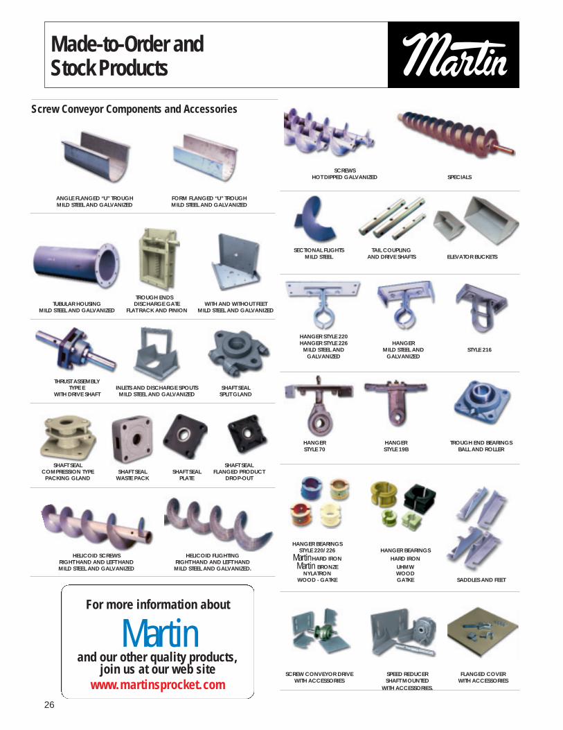
Made-to-Order andStock Products
ANGLE FLANGED “U” TROUGH FORM FLANGED “U” TROUGHMILD STEEL AND GALVANIZED MILD STEEL AND GALVANIZED
TROUGH ENDSTUBULAR HOUSING DISCHARGE GATE WITH AND WITHOUT FEET
MILD STEEL AND GALVANIZED FLAT RACK AND PINION MILD STEEL AND GALVANIZED
THRUST ASSEMBLYTYPE E INLETS AND DISCHARGE SPOUTS SHAFT SEAL
WITH DRIVE SHAFT MILD STEEL AND GALVANIZED SPLIT GLAND
SHAFT SEAL SHAFT SEALCOMPRESSION TYPE SHAFT SEAL SHAFT SEAL FLANGED PRODUCT
PACKING GLAND WASTE PACK PLATE DROP-OUT
HELICOID SCREWS HELICOID FLIGHTINGRIGHT HAND AND LEFT HAND RIGHT HAND AND LEFT HANDMILD STEEL AND GALVANIZED MILD STEEL AND GALVANIZED.
SCREWSHOT DIPPED GALVANIZED SPECIALS
SECTIONAL FLIGHTS TAIL COUPLINGMILD STEEL AND DRIVE SHAFTS ELEVATOR BUCKETS
HANGER STYLE 220HANGER STYLE 226 HANGER
MILD STEEL AND MILD STEEL AND STYLE 216GALVANIZED GALVANIZED
HANGER HANGER TROUGH END BEARINGSSTYLE 70 STYLE 19B BALL AND ROLLER
HANGER BEARINGSSTYLE 220/226 HANGER BEARINGS
Martin HARD IRON HARD IRONMartin BRONZE UHMW
NYLATRON WOODWOOD - GATKE GATKE SADDLES AND FEET
SCREW CONVEYOR DRIVE SPEED REDUCER FLANGED COVERWITH ACCESSORIES SHAFT MOUNTED WITH ACCESSORIES
WITH ACCESSORIES.
For more information about
Martinand our other quality products,
join us at our web sitewww.martinsprocket.com
Screw Conveyor Components and Accessories

27
Made-to-Order andStock Products
Stock QD V-Belt Sheaves
“3V” HI-CAP® “5V” HI-CAP® “8V” HI-CAP
Stock Tapered Bushed V-Belt Sheaves
CONVENTIONAL C SECTION “3V” HI-CAP® CONVENTIONAL B SECTIONTAPER BUSHED TAPER BUSHED TAPER BUSHED
Stock Couplings/Covers
RUBBER ELEMENT ROLLER CHAIN JAW COUPLINGMartin-FLEX® STOCK BORE COVERSSTOCK BORE
FINISHED BORE “QD” SC SPACER TPR ELEMENT
Martin’S NEW QUADRA-FLEX® COUPLING
Stock Sintered Metal and Sinteed Steel Products.
HANGER BEARINGS.
All Steel Stock Sprockets
BORED TO SIZE DOUBLE SINGLE SABER TOOTH® QDHARDENED TEETH HARDEND TEETH HARDENED TEETH TRIPLE
Stock Bushings/Hubs
BUSHINGS TYPE QD TAPERED QD IDLERSTEEL WITH KEYSEAT BUSHING BUDSHING
SIZE SF-N
Stock Gears/Steel and CastSpur Gears - Stocked in both 14-1/2º & 20º Pressure Angles
SPUR TYPE B SPUR 3 DP GEAR RACK
BEVEL MITER WORM GEAR WORM
Stock Timing Pulleys
TIMING PULLEY TIMING PULLEY TIMING PULLEYTAPERED BUSHING QD STOCK BORE
STOCK BORE QD MTO
Martin’S NEW HTS (HIGH TORQUE SPROCKETS)

Martin Sprocket & Gear, Inc. • 3100 Sprocket Drive Arlington, TX 76015 • 817-258-3000www.martinsprocket.com
For more information contact a branch near you:
COPYRIGHT 2013 • Martin SPROCKET & GEAR, INC. • ALL RIGHTS RESERVED 1180 PTC-HDCP 0513
USAGeneral Offices
Sales and ManufacturingArlington, TX3100 Sprocket Drive 76015-2898P.O. Box 91588Arlington, TX 76015-0088817-258-3000 (FAX 817-258-3333)
Regional Manufacturing PlantsAlbemarle, NC (Conveyor Pulley Div.)306 Bethany RoadAlbemarle, NC 28001-8520 704-982-9555 (FAX 704-982-9599)
Burleson, TX555 N. Burleson Blvd. Burleson, TX 76028817-295-7151 (FAX 817-447-3840)
Danielsville, PA3376 Delps Road 18038-9515P.O. Box 267 • Danielsville, PA 18038-0267610-837-1841 (FAX 610-837-7337)Ft. Worth, TX (Conveyor Div.)3600 McCart AvenueFt. Worth, TX 76110-4692817-258-3000 (FAX 817-258-3173) Ft. Worth, TX (Tool & Forge Div.)3600 McCart AvenueFt. Worth, TX 76110-4692817-258-3000 (FAX 817-258-3173)
Montpelier, OH350 S. Airport RoadMontpelier, OH 43543-9329419-485-5515 (FAX 419-485-3565)
Sacramento, CA1199 Vine Street Sacramento, CA 95814-0426916-441-7172 (FAX 916-441-4600)
Scottdale, GA3303 Church Street 30079-1395P.O. Box 886 • Scottdale, GA 30079-0886404-292-8744 (FAX 404-292-7771)
Branch Manufacturing CentersBoston, MA357 Fortune Boulevard Milford, MA 01757-1723508-634-3990 (FAX 508-634-3998)
Charlotte, NC3901 Scott Futrell DriveCharlotte, NC 28208-3539704-394-9111 (FAX 704-394-9122)
Chicago, IL 1505 Birchwood Avenue Des Plaines, IL 60018-3001847-298-8844 (FAX 847-298-2967)
Denver, CO10800 East 54th Avenue Denver CO 80239-2124303-371-8466 (FAX 303-371-7116)
Houston, TX 9910 Bent Oak Drive Houston, TX 77040-3222713-849-4330 (FAX 713-849-4807)
Kansas City, MO1520 North Commerce AvenueKansas City, MO 64120-4961816-231-5575 (FAX 816-231-1959)
Los Angeles, CA5920 South Triangle DriveCommerce, CA 90040-3639323-728-8117 (FAX 323-722-7526)
Minneapolis, MN10601 Hampshire Avenue South Bloomington, MN 55438-2395952-829-0623 (FAX 952-944-9385)
Nashville, TN732 Massman DriveNashville, Tennessee 37210615-871-4730 (FAX 615-871-4125)
Portland, OR3030 Northwest Industrial StreetPortland, OR 97210-1734503-223-7261 (FAX 503-221-0203)
Tampa, FL3201 Queen Palm Drive Tampa FL 33619-1331813-623-1705 (FAX 813-626-8953)
Wayne, NJ7 High Point Drive Wayne, NJ 07470-7432973-633-5700 (FAX 973-633-7196)
Manufacturing Only
Abilene, TX • Clarksville, TX
Dallas, TX • Mansfield, TX
Paragould, AR
CANADA Sales and ManufacturingMartin Sprocket & Gear Canada Inc.Edmonton, Alberta4023/4027 53rd Avenue, Edmonton, Alberta, Canada T6B 3C6 780-450-0888 (Fax 780-465-0079)
Mississauga, Ontario896 Meyerside DriveMississauga, Ontario, Canada L5T 1R9905-670-1991 (FAX 905-670-2110)
Ayr, Ontario (Conveyor Div.)320 Darrell DriveAyr, Ontario, Canada N0B 1E0519-621-0546 (FAX 519-621-4413)
MEXICOSales and ManufacturingMartin Sprocket & Gear de México, S.A. de C.V.Guadalajara, JALAv. Colón Sur No. 6013, Edificio 1 Modulo 2Colonia Santa María TequepexpanTlaquepaque, Jalisco Mexico 45601+52 33-3283-1188 ([email protected])
Monterrey, N.L.Av. Industrial No. 100Lote 6 y 7, Manzana 11Parque Industrial La Silla ApodacaApodaca, N.L. México 66648+52 811 156 6830 ([email protected])
Toluca, MEXKm 52 Carretera, Naucalpan-TolucaCalle 3, Manzana VII, Lote 11Parque Industrial Toluca 2000Toluca, Edo. de México 50233 +52 722 276 0800 ([email protected])
SOUTH AMERICASales and ManufacturingMartin Sprocket & Gear do BrazilSão Paulo, SPSP 332 Km 154,5Artur Nogueira – São PauloCEP 13160-000C.P. 138Tel: 19 3877 4500
CHINAAsia Division HeadquartersMartin Sprocket & Gear (Shanghai) Co., Ltd.81 Tang Yao Road, Hua Ting Town, Jiading District,Shanghai 201816, P. R. ChinaTel.: 86-021-67084888 Fax: 86-021-67084889
Changzhou • Fuzhou • WuhanZhongshan • Tianjin • Harbin
PEOPLE: When you call Martin you get a person, not voice mail. We are ready, able and willing to help...Now!
SERVICE: Martin ships rebores and other alterations within hours - not days...MTO’s in days - not weeks.
INVENTORY: Martin delivers with incredible fill rates from one of its many facilities strategically located across North America.