martinheusse lig/drakkarlig-membres.imag.fr/heusse/wirelessnet/slides-lora-eng.pdf · a channel...
TRANSCRIPT

LoRa
Martin Heusse LIG / Drakkar

LoRa — page 2 — transp. 2
Lora in the ISM bands channel spacing : 200kHz
• 433MHz Band
✓ Max Tx power 10dBm
• EU 863-870MHz Band✓ Max Tx power : 20dBm, by default 14dBm✓ Rx channels for the gateways
LoRaWAN Specification
©2015 LoRa™ Alliance Page 34 of 82 The authors reserve the right to change specifications without notice.
7 Physical Layer 1
7.1 EU 863-870MHz ISM Band 2
7.1.1 EU863-870 Preamble Format 3
The following synchronization words should be used: 4 5
Modulation Sync word Preamble length LORA 0x34 8 symbols GFSK 0xC194C1 5 bytes
Table 11: EU863-870 synch words 6
7.1.2 EU863-870 ISM Band channel frequencies 7
In Europe, radio spectrum allocation is the ISM band is defined by ETSI [EN300.220]. 8
The network channels can be freely attributed by the network operator. However the three 9 following default channels must be implemented in every EU868MHz end-device. Those 10 channels are the minimum set that all network gateways should always be listening on. 11 12 Modulation Bandwidth [kHz] Channel
Frequency [MHz]
FSK Bitrate or LoRa DR / Bitrate
Nb Channels
Duty cycle
LoRa 125 868.10 868.30 868.50
DR0 to DR5
/ 0.3-5 kbps
3 <1%
Table 12: EU863-870 default channels 13
In order to access the physical medium the ETSI regulations impose some restrictions such 14 maximum time the transmitter can be on or the maximum time a transmitter can transmit per 15 hour. The ETSI regulations allow the choice of using either a duty-cycle limitation or a so-16 called Listen Before Talk Adaptive Frequency Agility (LBT AFA) transmissions 17 management. The current LoRaWAN specification exclusively uses duty-cycled limited 18 transmissions to comply with the ETSI regulations. 19
The LoRaWAN enforces a per sub-band duty-cycle limitation. Each time a frame is 20 transmitted in a given sub-band, the time of emission and the on-air duration of the frame 21 are recorded for this sub-band. The same sub-band cannot be used again during the next 22 Toff seconds where: 23
Toff = TimeOnAir
DutyCycle − TimeOnAir
During the unavailable time of a given sub-band, the device may still be able to transmit on 24 another sub-band. If all sub-bands are unavailable, the device has to wait before any further 25 transmission. The device adapts its channel hoping sequence according to the sub-band 26 availability. 27
Example: A device just transmitted a 0.5 s long frame on one default channel. This channel 28 is in a sub-band allowing 1% duty-cycle. Therefore this whole sub-band (868 – 868.6) will be 29 unavailable for 49.5 s. 30
✓ Duty cycle is computed per sub band✓ Each gateway may listen to 16 canaux in parallel.
Specified to the devices when they associate
LoRa — page 3 — transp. 3
Lora in the ISM bands channel spacing : 200kHz (cont.)
LoRaWAN Specification
©2015 LoRa™ Alliance Page 35 of 82 The authors reserve the right to change specifications without notice.
EU868MHz ISM band end-devices should use the following default parameters 1 x Default radiated transmit output power: 14 dBm 2
EU868Mhz end-devices should be capable of operating in the 863 to 870 MHz frequency 3 band and should feature a channel data structure to store the parameters of at least 16 4 channels. A channel data structure corresponds to a frequency and a set of data rates 5 usable on this frequency. 6
The first three channels correspond to 868.1, 868.3, and 868.5 MHz / DR0 to DR5 and must 7 be implemented in every end-device. Those default channels cannot be modified through 8 the NewChannelReq command and guarantee a minimal common channel set between 9 end-devices and network gateways. 10
The following table gives the list of frequencies that should be used by end-devices to 11 broadcast the JoinReq message. The JoinReq message transmit duty-cycle should never 12 exceed 0.1% 13 14 Modulation Bandwidth [kHz] Channel
Frequency [MHz]
FSK Bitrate
or LoRa DR
/ Bitrate
Nb Channels
Duty cycle
LoRa
125 864.10 864.30 864.50 868.10 868.30 868.50
DR0 – DR5
/ 0.3-5 kbps
6 <0.1%
Table 13: EU863-870 JoinReq Channel List 15
7.1.3 EU863-870 Data Rate and End-point Output Power encoding 16
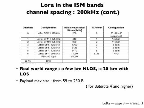
The following encoding is used for Data Rate (DR) and End-point Output Power (TXPower) 17 in the EU863-870 band: 18 DataRate Configuration Indicative physical
bit rate [bit/s] TXPower Configuration
0 LoRa: SF12 / 125 kHz 250 0 20 dBm (if supported)
1 LoRa: SF11 / 125 kHz 440 1 14 dBm 2 LoRa: SF10 / 125 kHz 980 2 11 dBm 3 LoRa: SF9 / 125 kHz 1760 3 8 dBm 4 LoRa: SF8 / 125 kHz 3125 4 5 dBm 5 LoRa: SF7 / 125 kHz 5470 5 2 dBm 6 LoRa: SF7 / 250 kHz 11000 6..15 RFU 7 FSK: 50 kbps 50000
8..15 RFU Table 14: Data rate and TX power table 19
7.1.4 EU863-870 JoinAccept CFList 20 21
The EU 863-870 ISM band LoRaWAN implements an optional channel frequency list 22 (CFlist) of 16 octets in the JoinAccept message. 23
• Real world range : a few km NLOS, ≈ 20 km withLOS
• Payload max size : from 59 to 230 B( for datarate 4 and higher)
LoRa — page 4 — transp. 4
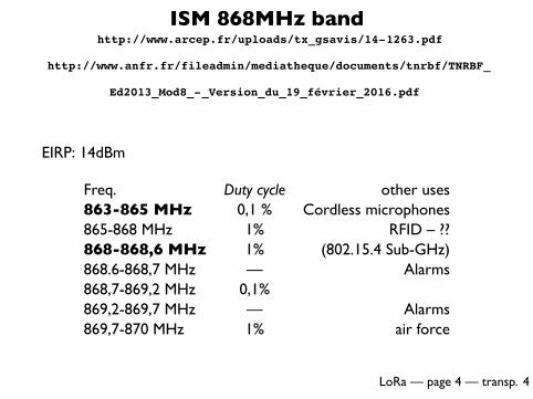
ISM 868MHz band http://www.arcep.fr/uploads/tx_gsavis/14-1263.pdf
http://www.anfr.fr/fileadmin/mediatheque/documents/tnrbf/TNRBF_
Ed2013_Mod8_-_Version_du_19_février_2016.pdf
EIRP: 14dBm
Freq. Duty cycle other uses863-865 MHz 0,1 % Cordless microphones865-868 MHz 1% RFID – ??868-868,6 MHz 1% (802.15.4 Sub-GHz)868.6-868,7 MHz — Alarms868,7-869,2 MHz 0,1%869,2-869,7 MHz — Alarms869,7-870 MHz 1% air force

LoRa — page 5 — transp. 5
ERC Recommendation 70-03
http://www.erodocdb.dk/docs/doc98/official/pdf/rec7003e.pdf
Sub band Freq. (MHz) Power Duty cycle BW (MHz)h1.3 863-870 14 dBm 0.1% 7h1.4 868-868.6 14 dBm 1% 0.6h1.5 868.7-869.2 14 dBm 0.1% 0.5h1.6 869.4-869.65 27 dBm 10% 0.25h1.7 869.7-870 7 dBm 100% 0.3h1.7 869.7-870 14 dBm 1 % 0.3
Duty cycles are computed per sub-band : a device may consume 1% inh1.4, 10% in h1.6, 1% in h1.7, during the same hour for instance
h1.4 encompasses the 3 defaults LoRa channels,h1.6 is used by the GW to respond to the devices (cf. RX2)

LoRa — page 6 — transp. 6
Transmissions• Classe A (All devices)✓ Exchange always initiated by the device Aloha access✓ 2 rx windows follow the transmission
at +1 s (same channel as TX) and +2 s (channel and SF fixed inadvance)
LoRaWAN Specification
©2015 LoRa™ Alliance Page 13 of 82 The authors reserve the right to change specifications without notice.
1 Figure 4: End-device receive slot timing. 2
3.3.1 First receive window channel, data rate, and start 3
The first receive window RX1 uses the same frequency channel as the uplink and a data 4 rate that is a function of the data rate used for the uplink. RX1 opens RECEIVE_DELAY11 5 seconds (+/- 20 microseconds) after the end of the uplink modulation. The relationship 6 between uplink and RX1 slot downlink data rate is region specific and detailed in the Section 7 7. By default the first receive window datarate is identical to the datarate of the last uplink. 8
3.3.2 Second receive window channel, data rate, and start 9
The second receive window RX2 uses a fixed configurable frequency and data rate and 10 opens RECEIVE_DELAY21 seconds (+/- 20 microseconds) after the end of the uplink 11 modulation. The frequency and data rate used can be modified through MAC commands 12 (see Section 5).The default frequency and data rate to use are region specific and detailed 13 in the Section 7 . 14
3.3.3 Receive window duration 15
The length of a receive window must be at least the time required by the end-device‘s radio 16 transceiver to effectively detect a downlink preamble. 17
3.3.4 Receiver activity during the receive windows 18
If a preamble is detected during one of the receive windows, the radio receiver stays active 19 until the downlink frame is demodulated. If a frame was detected and subsequently 20 demodulated during the first receive window and the frame was intended for this end-device 21 after address and MIC (message integrity code) checks, the end-device does not open the 22 second receive window. 23
3.3.5 Network sending a message to an end-device 24
If the network intends to transmit a downlink to an end-device, it will always initiate the 25 transmission precisely at the beginning of one of those two receive windows. 26
1 RECEIVE_DELAY1 and RECEIVE_DELAY2 are described in Chapter 6.
By default : RX2 at 869.525 MHz (center of h1.6), DR0 (SF12,125 kHz)
✓ Each frame carries the Confirmed bit: (expecting and ACK) orunconfirmed
• Classe B : Beacons Device listen periodically to beacons. Regular downlinkslots are defined relative to the beacon
• classe C : Continuous reception

LoRa — page 7 — transp. 7
LoRaWAN
GW
GW
Network Server
App Server
App Server
App Server
LoRa / JSON / UDP SSL/TCP/IP
Concentrator
Concentrator

LoRa — page 8 — transp. 8
LoRaWAN (cont.)
LoRaWAN Specification
©2015 LoRa™ Alliance Page 15 of 82 The authors reserve the right to change specifications without notice.
4 MAC Message Formats 1
All LoRa uplink and downlink messages carry a PHY payload (Payload) starting with a 2 single-octet MAC header (MHDR), followed by a MAC payload (MACPayload)1, and ending 3 with a 4-octet message integrity code (MIC). 4 5
Radio PHY layer: 6 Preamble PHDR PHDR_CRC PHYPayload CRC*
Figure 5: Radio PHY structure (CRC* is only available on uplink messages) 7
PHYPayload: 8 MHDR MACPayload MIC
Figure 6: PHY payload structure 9
MACPayload: 10 FHDR FPort FRMPayload
Figure 7: MAC payload structure 11
FHDR: 12 DevAddr FCtrl FCnt FOpts
Figure 8: Frame header structure 13
Figure 9: LoRa message format elements 14
4.1 MAC Layer (PHYPayload) 15 16
Size (bytes) 1 1..M 4 PHYPayload MHDR MACPayload MIC
17
The maximum length (M) of the MACPayload field is region specific and is specified in 18 Chapter 6. 19
4.2 MAC Header (MHDR field) 20 21
Bit# 7..5 4..2 1..0 MHDR bits MType RFU Major
22
The MAC header specifies the message type (MType) and according to which major version 23 (Major) of the frame format of the LoRaWAN layer specification the frame has been 24 encoded. 25
1 Maximum payload size is detailed in the Chapter 6.
4B1B …
4B 1B 2B 0…15B
0 or 1B …

LoRa — page 9 — transp. 9
LoRaWAN (cont.)
• The frames only carry a single address, the devicesource/destination
• Application demultiplexing : “FPort” (0: pure MAC command)
• Piggybacking of MAC commands (power, data rate, channels,device state, rx delay1 … ) in the will typically get several copiesof the same frame (they have a seq. number)
The net. server selects the best GW for a reply (if applicable)
• In the core networks, the frames are forwarded with quite a bitof ancillary data (power, timestamp…)
1RX2 is always 1 s behind RX1
LoRa — page 10 — transp. 10
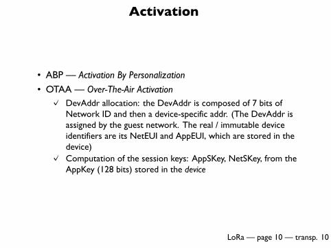
Activation
• ABP — Activation By Personalization
• OTAA — Over-The-Air Activation✓ DevAddr allocation: the DevAddr is composed of 7 bits of
Network ID and then a device-specific addr. (The DevAddr isassigned by the guest network. The real / immutable deviceidentifiers are its NetEUI and AppEUI, which are stored in thedevice)
✓ Computation of the session keys: AppSKey, NetSKey, from theAppKey (128 bits) stored in the device

LoRa — page 11 — transp. 11
What is a chirp ?CSS : Chirp Spread Spectrum
• A linear frequency sweep/ramp −BW2 < f < BW
2
−4 −2 0 2 4
−1.
0−
0.5
0.0
0.5
1.0
t
tx(x
)
• Used by radars, bats, dolphins…

LoRa — page 12 — transp. 12
Coding information on a chirp
• It is the start freq. offset that codes the information (line 514)
Drawing pages of EP2449690 A1

LoRa — page 13 — transp. 13
Reception
• Multiplication of rx signal with a complex conjugate chirp (downchirp)
e2πjt[f0+(at+b) mod BW] × e−2πjt[f0+(at) mod BW]
= e2πjt[b mod BW]
N.B. : a = BW2
2SF→ sweep BW in time 2SF
BW

LoRa — page 14 — transp. 14
Reception (cont.)
• if both chirps are in sync, we get a constant, otherwise
Drawing pages of EP2449690 A1

LoRa — page 15 — transp. 15
FFT-based reception
• FFT after sampling at rate BW
• The symbol duration is N/BW → N samples
• By frequency aliasing, a single frequency appears in theFFT !

LoRa — page 16 — transp. 16
Spread spectrum
• Spreading factors from 7 to 12 ⇔ N goes from 27 to 212, 7 to 12 bits per symbol
• The bigger the SF the longer the chirp— 33ms @ SF12. For LoRa, the preamble is also proportional to theSF�� ��The actual SF dynamics are ≈ 20 Rb = SF× BW
2SF
• Error correcting codes R = 45
• The actual max. SF is ≈ 340 (212/12), so a transmission maysurvive a collision with a node closer by a ratio of ≈
√340

LoRa — page 17 — transp. 17
Frame sizes
• Depends on SF : 51B payload at SF12, 242 at SF8 and SF7…
• 51B @ SF12 → 1,3 s of continuous transmission!
LoRa — page 18 — transp. 18
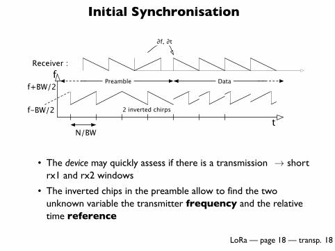
Initial Synchronisation
t
f
f-BW/2
f+BW/2
N/BW
Preamble
∂f, ∂t
Receiver :
Data
2 inverted chirps
• The device may quickly assess if there is a transmission → shortrx1 and rx2 windows
• The inverted chips in the preamble allow to find the twounknown variable the transmitter frequency and the relativetime reference

LoRa — page 19 — transp. 19
Localization
• The observed δt at several GW allow to compute relative timeof arrival
• Trilateration
• Time ref. from GPS at the GWs

LoRa — page 20 — transp. 20
A few remarks
• A receiver can receive at several SF simultaneously (≈ 30 dB)2.
• It needs as many reception circuits as there are SFs 7 channels (6 CSS + 1 FSK) on all LoRa GWs
• Localization is a by product of PHY initial sync.• Cell breathing✓ Having more GWs allows :
▶ Lower the SF for closer devices▶ lower the power
2C. Goursaud & J.M. Gorce : “Dedicated networks for IoT : PHY / MAC state ofthe art and challenges”