masonry infill walls in reinforced concrete frames...
TRANSCRIPT
Masonry infill walls in reinforced concrete frames as a sourceof structural damping
H. Ozkaynak1, E. Yuksel2,*,†, C. Yalcin3, A. A. Dindar4 and O. Buyukozturk5
1Department of Civil Engineering, Beykent University, Istanbul, Turkey2Faculty of Civil Engineering, Istanbul Technical University, Istanbul, Turkey
3Department of Civil Engineering, Bogazici University, Istanbul, Turkey4Department of Civil Engineering, Istanbul Kultur University, Istanbul, Turkey
5Civil and Environmental Engineering, Massachusetts Institute of Technology, Cambridge, MA, USA
SUMMARY
This paper presents the results of an experimental study on the determination of damping characteristics of bare,masonry infilled, and carbon fiber reinforced polymer retrofitted infilled reinforced concrete (RC) frames. It iswell known that the masonry infills are used as partitioning walls having significant effect on the dampingcharacteristics of structures as well as contribution to the lateral stiffness and strength. The main portion ofthe input energy imparted to the structure during earthquakes is dissipated through hysteretic and dampingenergies. The equivalent damping definition is used to reflect various damping mechanisms globally. In thisstudy, the equivalent damping ratio of carbon fiber reinforced polymer retrofitted infilled RC systems isquantified through a series of 1/3-scaled, one-bay, one-story frames. Quasi-static tests are carried out on eightspecimens with two different loading patterns: one-cycled and three-cycled displacement histories and thepseudo-dynamic tests performed on eight specimens for selected acceleration record scaled at three differentPGA levels with two inertia mass conditions. The results of the experimental studies are evaluated in twophases: (i) equivalent damping is determined for experimentally obtained cycles from quasi-static andpseudo-dynamic tests; and (ii) an iterative procedure is developed on the basis of the energy balance formula-tion to determine the equivalent damping ratio. On the basis of the results of these evaluations, equivalentdamping of levels of 5%, 12%, and 14% can be used for bare, infilled, and retrofitted infilled RC frames, respec-tively. Copyright © 2013 John Wiley & Sons, Ltd.
Received 6 August 2012; Revised 13 September 2013; Accepted 20 September 2013
KEY WORDS: masonry infilled frames; CFRP retrofitting; damping; equivalent damping; energy methods
1. INTRODUCTION
Past earthquakes and research demonstrated that the masonry infill walls have advantages in theimprovement of energy dissipation as well as increase of stiffness and strength properties ofreinforced concrete (RC) structures when they are placed regularly throughout the structure and/orthey do not cause shear failures of columns, [1]. Damping in RC structures arises through energydissipation by various mechanisms such as cracking of concrete and sliding between structural andnonstructural elements. Because it is very difficult and also unpractical to directly calculate thedamping, experimental research is essential in order to determine a range of such energy dissipationcharacteristic. A review is given in the following:
Buttmann [2] conducted an experimental study on the specimens with the dimensions of100 × 200 × 11.5 cm and 24 cm. The horizontal sinusoidal excitation applied to the specimens was
*Correspondence to: Ercan Yuksel, Faculty of Civil Engineering, Istanbul Technical University, Istanbul, Turkey.†E-mail: [email protected]
Copyright © 2013 John Wiley & Sons, Ltd.
EARTHQUAKE ENGINEERING & STRUCTURAL DYNAMICSEarthquake Engng Struct. Dyn. 2014; 43:949–968Published online 14 October 2013 in Wiley Online Library (wileyonlinelibrary.com). DOI: 10.1002/eqe.2380
generated by a dynamic oscillator with a maximum power of 20 kN. The experimental study yieldedcritical damping ratios of 11% for shear walls and 24% for masonry walls. Farrar and Baker [3]performed an experimental study on 1/3-scaled low aspect ratio RC shear walls. It was concluded thatwithin elastic range of the testing, damping ratio was found to be 2%, and when the damages increasedand re-bars yielded, this value increased up to 22%. Fardis and Panagiotakos [4] evaluated pseudo-dynamic tests (PsD) test results that were conducted in ELSA Laboratory by Negro and Verzeletti [5].It was concluded that the infills resulted damping after the first cracks observed. It was stated that thehysteretic energy dissipation occurred through the masonry infills. Also, the response spectra of an elasticsingle degree of freedom system infilled frame, despite infill’s apparent stiffening effect on the system, areduction in the spectral displacement and forces were obtained mainly through high level damping.Hashemi and Mosalam [6, 7] conducted shake table tests on 3/4-scaled, three dimensional infilled RCframes. The tests resulted nearly four times higher structural stiffness, shortened natural period nearly50%, increased damping coefficient from about 4% to 12%, and also increased the energy dissipationcapacity of the system.
Costa et al. [8] performed in situ tests on masonry walls of abandoned traditional houses. Five spec-imens were tested aiming at characterizing the out-of-plane behavior of stone masonry walls andstrengthening solutions recommended for post-earthquake interventions. Even for small drift valuesas 0.1%, the hysteresis is significant leading to an equivalent hysteretic damping value of 12%mainly explained by permanent deformations developed at the joints already for small displacementlevels. The evolution of hysteretic damping is almost linear with the evolution of drift up to theformation of a complete diagonal crack to the foundation, which occurred for the drift cycle of0.75%. This led to significant residual deformations along the wall and an equivalent hystereticdamping level of 26%. The final part of the test (drift of 1.0 and 1.25%) shows a constant hystereticdamping level close to 25% as a result of the severe damage observed and permanent deformationsof the wall.
Sofronie [9] indicated that the masonry walls act as active dampers when strengthened with FRP byincreasing frictional forces between wall elements resulting in higher damping. Santa-Maria et al.[10] conducted experimental studies on masonry walls under the effect of monotonic and cyclicloadings. The masonry specimens were retrofitted by horizontal, vertical, and diagonally bracedFRP. Especially horizontally retrofitted specimen displayed a great increase in damping. Elgawadyet al. [11] investigated the behaviors of seven specimens of 1/2-scaled FRP retrofitted masonry wallsunder cyclic displacement reversals. FRP caused a great increase in lateral stiffness, strength, andenergy dissipation capacity. The damping values were also determined for each specimen at varyingdrift levels. FRP confinement provided increase in damping ratios. Some of the specimens wereretrofitted after being tested, and these specimens produced higher values of structural damping.
Although various experimental studies have been conducted on the determination of dampingcharacteristics of masonry walls and masonry infilled RC frames; for the quantification of equivalentdamping, there is an apparent gap in the literature on carbon FRP (CFRP)-retrofitted infilled frames.There is a necessity about the damping characteristic, which is particularly important for theaccurate estimation of seismic forces, of CFRP-retrofitted infilled RC frames for the development ofrealistic structural models.
In this paper, a new concept based on the energy balance is proposed to quantify the dampingcharacteristic of the specimens.
The scope of this experimental study is limited to 16 specimens of 1/3-scaled one-bay, one-story RCframes subjected to quasi-static (QS) and PsD tests. The test results are used in the quantification ofequivalent damping ratios for bare, masonry infilled, and CFRP-retrofitted masonry infilled RC frames.
2. EXPERIMENTAL STUDY
The experimental study is conducted on sixteen 1/3-scaled one-bay, one-story RC frame, which istaken out from a three-span and five-story RC building. The specimens were built according to the
950 H. OZKAYNAK ET AL.
Copyright © 2013 John Wiley & Sons, Ltd. Earthquake Engng Struct. Dyn. 2014; 43:949–968DOI: 10.1002/eqe
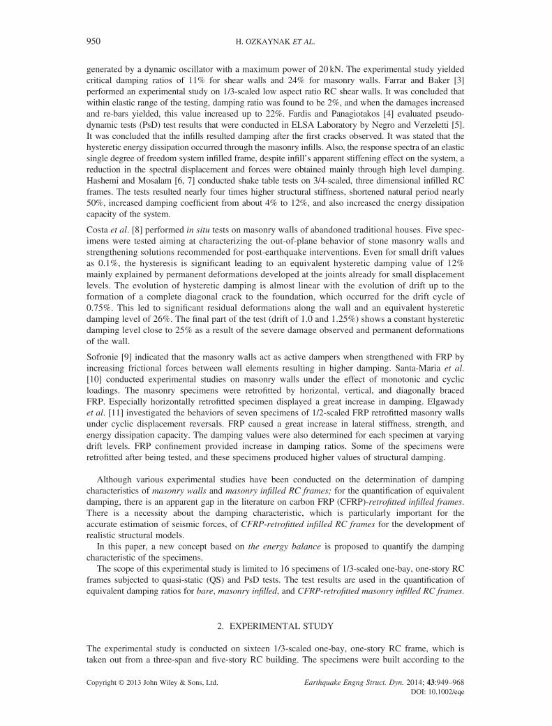
old construction practice, which had several variances with the current seismic design code of Turkey[12]. Dimensions and reinforcement details of the specimen are illustrated in Figure 1(a). Longitudinalreinforcement ratio in columns and beam is 1%, whereas transverse reinforcement ratio is around 0.4%.No confinement reinforcement in and around beam-column connections are used. Compression strengthof concrete is obtained 19MPa from the standard cylinder tests, which corresponds to the strength at theday of testing. Yield strength of reinforcements is 420 and 500MPa for eight and 6mm diameters,respectively.
The clay type brick used in the infill wall has a dimension of 87 × 84 × 56mm, Figure 1(b). Bothsides of infill wall were plastered having a thickness of 10mm. Compression tests of the masonrywallets with the dimensions of 350 × 350 × 56mm resulted compression strengths of 5.0 and4.1MPa in the two perpendicular directions. The diagonal tension (shear) test defined in ASTME519–02 [13] was applied, and the shear strength of 0.95MPa is reached [14]. As per the technicaldata provided by the manufacturer, the unit weight of the CFRP is 300 g/m2, the fiber density is1.79 g/cm3, and the modulus of elasticity of CFRP is 230GPa, where the tensile strength andultimate elongation capacities are 3900MPa and 1.5%, respectively. Special anchorages wereprovided along the CFRP sheets at approximately quarter distances of the diagonal with the lengthof the 24 cm, which will be enough to cover the CFRP strips applied on both sides of the infill. TheCFRP sheet was rolled with enough amount of epoxy and was installed in the infill through thebricks, Figure 1(c).
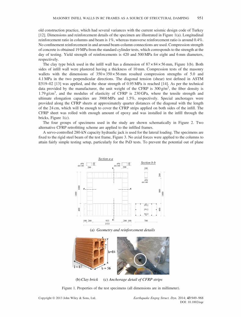
The four groups of specimens used in the study are shown schematically in Figure 2. Twoalternative CFRP retrofitting scheme are applied to the infilled frames.
A servo-controlled 280-kN capacity hydraulic jack is used for the lateral loading. The specimens arefixed to the rigid steel beam of the test frame, Figure 3. No axial forces were applied to the columns toattain fairly simple testing setup, particularly for the PsD tests. To prevent the potential out of plane
(a)
(b) (c)
Geometry and reinforcement details
Anchorage detail of CFRP stripsClay brick
Figure 1. Properties of the test specimens (all dimensions are in millimeter).
MASONRY INFILL WALLS IN RC FRAMES AS A SOURCE OF STRUCTURAL DAMPING 951
Copyright © 2013 John Wiley & Sons, Ltd. Earthquake Engng Struct. Dyn. 2014; 43:949–968DOI: 10.1002/eqe
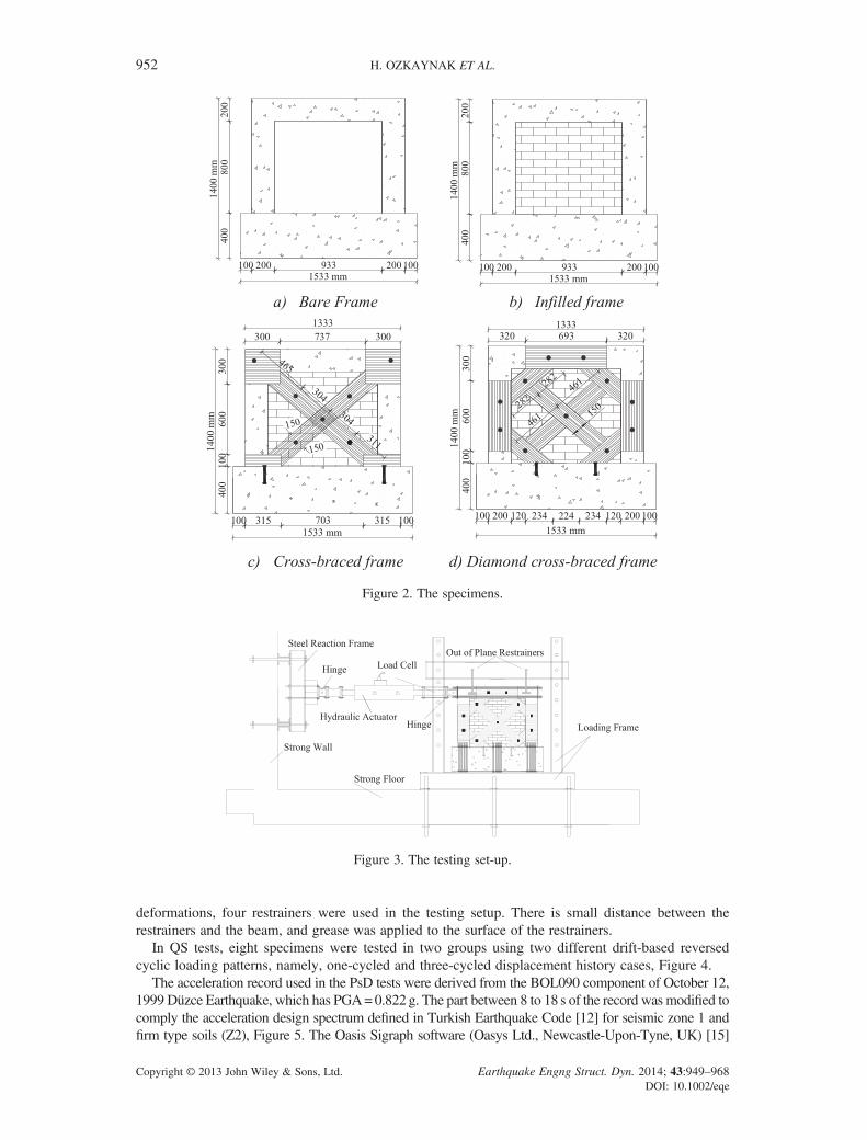
deformations, four restrainers were used in the testing setup. There is small distance between therestrainers and the beam, and grease was applied to the surface of the restrainers.
In QS tests, eight specimens were tested in two groups using two different drift-based reversedcyclic loading patterns, namely, one-cycled and three-cycled displacement history cases, Figure 4.
The acceleration record used in the PsD tests were derived from the BOL090 component of October 12,1999 Düzce Earthquake, which has PGA=0.822g. The part between 8 to 18 s of the record was modified tocomply the acceleration design spectrum defined in Turkish Earthquake Code [12] for seismic zone 1 andfirm type soils (Z2), Figure 5. The Oasis Sigraph software (Oasys Ltd., Newcastle-Upon-Tyne, UK) [15]
Figure 2. The specimens.
Figure 3. The testing set-up.
952 H. OZKAYNAK ET AL.
Copyright © 2013 John Wiley & Sons, Ltd. Earthquake Engng Struct. Dyn. 2014; 43:949–968DOI: 10.1002/eqe
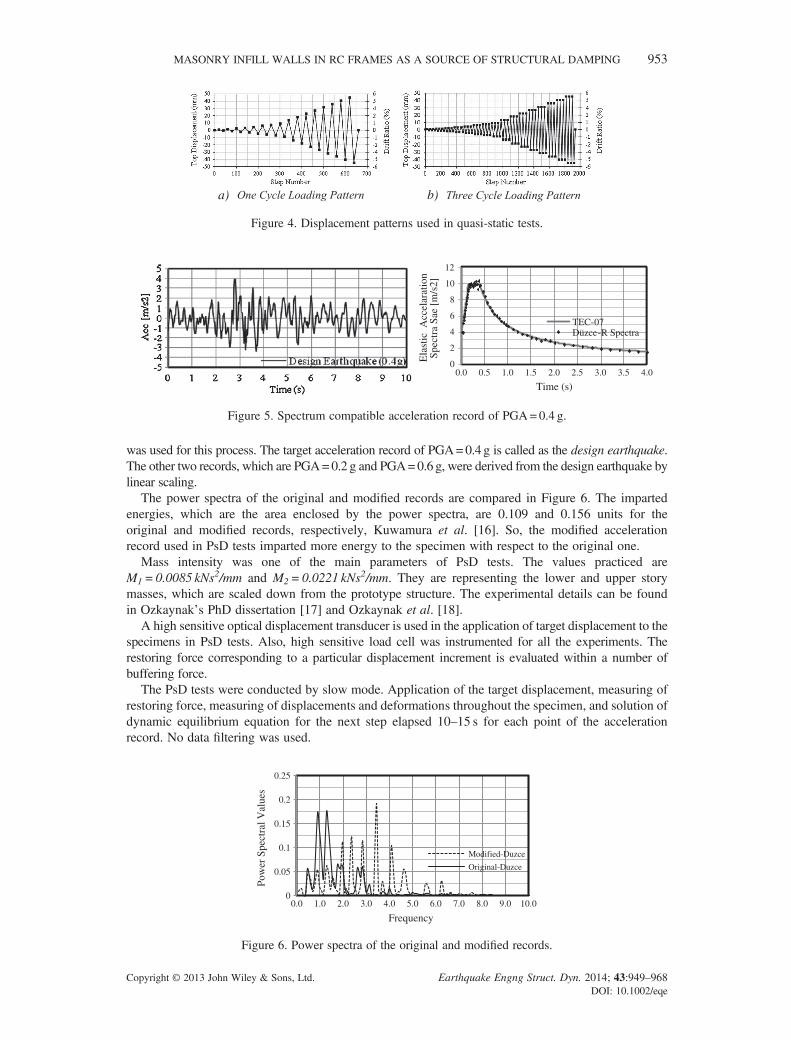
was used for this process. The target acceleration record of PGA=0.4 g is called as the design earthquake.The other two records, which are PGA=0.2 g and PGA=0.6 g, were derived from the design earthquake bylinear scaling.
The power spectra of the original and modified records are compared in Figure 6. The impartedenergies, which are the area enclosed by the power spectra, are 0.109 and 0.156 units for theoriginal and modified records, respectively, Kuwamura et al. [16]. So, the modified accelerationrecord used in PsD tests imparted more energy to the specimen with respect to the original one.
Mass intensity was one of the main parameters of PsD tests. The values practiced areM1=0.0085 kNs2/mm and M2= 0.0221 kNs2/mm. They are representing the lower and upper storymasses, which are scaled down from the prototype structure. The experimental details can be foundin Ozkaynak’s PhD dissertation [17] and Ozkaynak et al. [18].
A high sensitive optical displacement transducer is used in the application of target displacement to thespecimens in PsD tests. Also, high sensitive load cell was instrumented for all the experiments. Therestoring force corresponding to a particular displacement increment is evaluated within a number ofbuffering force.
The PsD tests were conducted by slow mode. Application of the target displacement, measuring ofrestoring force, measuring of displacements and deformations throughout the specimen, and solution ofdynamic equilibrium equation for the next step elapsed 10–15 s for each point of the accelerationrecord. No data filtering was used.
a) b)
Figure 4. Displacement patterns used in quasi-static tests.
0
2
4
6
8
10
12
0.0 0.5 1.0 1.5 2.0 2.5 3.0 3.5 4.0
Ela
stic
Acc
elar
atio
n Sp
ectr
a Sa
e [m
/s2]
Time (s)
TEC-07Düzce-R Spectra
Figure 5. Spectrum compatible acceleration record of PGA=0.4 g.
0
0.05
0.1
0.15
0.2
0.25
0.0 1.0 2.0 3.0 4.0 5.0 6.0 7.0 8.0 9.0 10.0
Pow
er S
pect
ral V
alue
s
Frequency
Modified-Duzce
Original-Duzce
Figure 6. Power spectra of the original and modified records.
MASONRY INFILL WALLS IN RC FRAMES AS A SOURCE OF STRUCTURAL DAMPING 953
Copyright © 2013 John Wiley & Sons, Ltd. Earthquake Engng Struct. Dyn. 2014; 43:949–968DOI: 10.1002/eqe
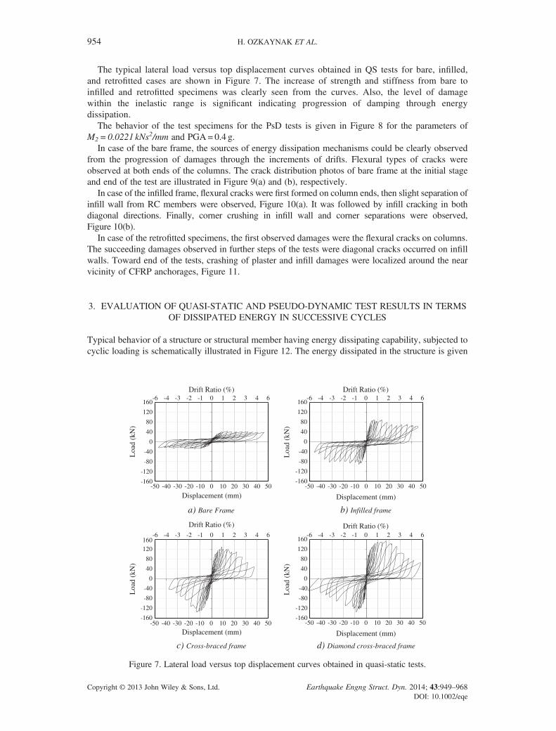
The typical lateral load versus top displacement curves obtained in QS tests for bare, infilled,and retrofitted cases are shown in Figure 7. The increase of strength and stiffness from bare toinfilled and retrofitted specimens was clearly seen from the curves. Also, the level of damagewithin the inelastic range is significant indicating progression of damping through energydissipation.
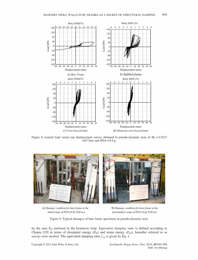
The behavior of the test specimens for the PsD tests is given in Figure 8 for the parameters ofM2=0.0221 kNs2/mm and PGA=0.4 g.
In case of the bare frame, the sources of energy dissipation mechanisms could be clearly observedfrom the progression of damages through the increments of drifts. Flexural types of cracks wereobserved at both ends of the columns. The crack distribution photos of bare frame at the initial stageand end of the test are illustrated in Figure 9(a) and (b), respectively.
In case of the infilled frame, flexural cracks were first formed on column ends, then slight separation ofinfill wall from RC members were observed, Figure 10(a). It was followed by infill cracking in bothdiagonal directions. Finally, corner crushing in infill wall and corner separations were observed,Figure 10(b).
In case of the retrofitted specimens, the first observed damages were the flexural cracks on columns.The succeeding damages observed in further steps of the tests were diagonal cracks occurred on infillwalls. Toward end of the tests, crashing of plaster and infill damages were localized around the nearvicinity of CFRP anchorages, Figure 11.
3. EVALUATION OF QUASI-STATIC AND PSEUDO-DYNAMIC TEST RESULTS IN TERMSOF DISSIPATED ENERGY IN SUCCESSIVE CYCLES
Typical behavior of a structure or structural member having energy dissipating capability, subjected tocyclic loading is schematically illustrated in Figure 12. The energy dissipated in the structure is given
-6 -4 -3 -2 -1 0 1 2 3 4 6
-160
-120
-80
-40
0 0
40
80
120
160
-50 -40 -30 -20 -10 0 10 20 30 40 50
Drift Ratio (%)
Loa
d (k
N)
Displacement (mm)
-6 -4 -3 -2 -1 0 1 2 3 4 6
-160
-120
-80
-40
40
80
120
160
-50 -40 -30 -20 -10 0 10 20 30 40 50
Drift Ratio (%)
Loa
d (k
N)
Displacement (mm)
-6 -4 -3 -2 -1 0 1 2 3 4 6
-160
-120
-80
-40
0 0
40
80
120160
-50 -40 -30 -20 -10 0 10 20 30 40 50
Drift Ratio (%)
Loa
d (k
N)
Displacement (mm)
-6 -4 -3 -2 -1 0 1 2 3 4 6
-160
-120
-80
-40
40
80
120
160
-50 -40 -30 -20 -10 0 10 20 30 40 50
Drift Ratio (%)
Loa
d (k
N)
Displacement (mm)
a) Bare Frame b) Infilled frame
c) Cross-braced frame d) Diamond cross-braced frame
Figure 7. Lateral load versus top displacement curves obtained in quasi-static tests.
954 H. OZKAYNAK ET AL.
Copyright © 2013 John Wiley & Sons, Ltd. Earthquake Engng Struct. Dyn. 2014; 43:949–968DOI: 10.1002/eqe
by the area EH enclosed in the hysteresis loop. Equivalent damping ratio is defined according toChopra [19] in terms of dissipated energy (EH) and strain energy (ES0), hereafter referred to asenergy ratio method. The equivalent damping ratio ζ eq is given by Eq. 1.
Story Drift(%)
Loa
d (k
N)
Story Drift (%)
Loa
d (k
N)
a) Bare Frame b) Infilled frame
Loa
d (k
N)
Loa
d (k
N)
c) Cross-braced frame d) Diamond cross-braced frame
-6 -4 -3 -2 -1 0 1 2 3 4 6
-160
-120
-80
-40
0 0
40
80
160
120
-50 -40 -30 -20 -10 0 10 20 30 40 50
Displacement (mm)
-6 -4 -3 -2 -1 0 1 2 3 4 6
-160
-120
-80
-40
40
80
120
160
-50 -40 -30 -20 -10 0 10 20 30 40 50
Displacement (mm)
Story Drift(%) Story Drift (%)-6 -4 -3 -2 -1 0 1 2 3 4 6
-160
-120
-80
-40
0 0
40
80
160
120
-50 -40 -30 -20 -10 0 10 20 30 40 50
Displacement (mm)
-6 -4 -3 -2 -1 0 1 2 3 4 6
-160
-120
-80
-40
40
80
120
160
-50 -40 -30 -20 -10 0 10 20 30 40 50
Displacement (mm)
Figure 8. Lateral load versus top displacement curves obtained in pseudo-dynamic tests of M2=0.0221kNs2/mm and PGA=0.4 g.
a) Damage condition for bare frame at the initial stage of PGA=0.2g PsD test
b) Damage condition for bare frame at the intermediary stage of PGA=0.4g PsD test
Figure 9. Typical damages of bare frame specimens in pseudo-dynamic tests.
MASONRY INFILL WALLS IN RC FRAMES AS A SOURCE OF STRUCTURAL DAMPING 955
Copyright © 2013 John Wiley & Sons, Ltd. Earthquake Engng Struct. Dyn. 2014; 43:949–968DOI: 10.1002/eqe
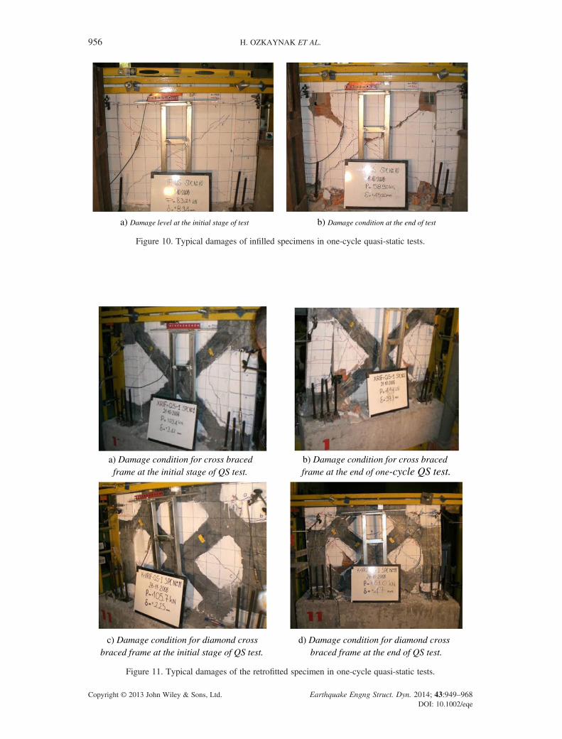
a) Damage level at the initial stage of test b) Damage condition at the end of test
Figure 10. Typical damages of infilled specimens in one-cycle quasi-static tests.
c) Damage condition for diamond cross braced frame at the initial stage of QS test.
d) Damage condition for diamond cross braced frame at the end of QS test.
frame at the initial stage of QS test. frame at the end of one-cycle QS test.a) Damage condition for cross braced b) Damage condition for cross braced
Figure 11. Typical damages of the retrofitted specimen in one-cycle quasi-static tests.
956 H. OZKAYNAK ET AL.
Copyright © 2013 John Wiley & Sons, Ltd. Earthquake Engng Struct. Dyn. 2014; 43:949–968DOI: 10.1002/eqe
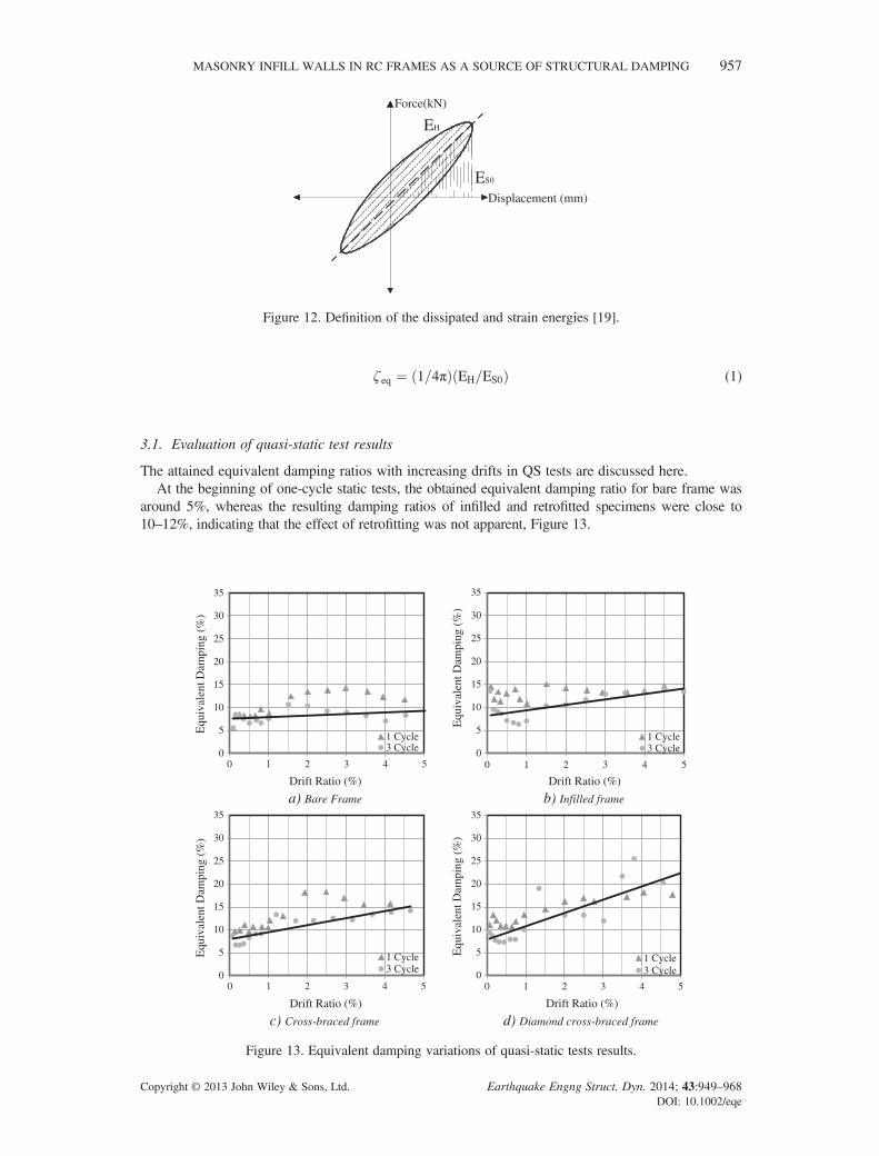
ζ eq ¼ 1=4πð Þ EH=ES0ð Þ (1)
3.1. Evaluation of quasi-static test results
The attained equivalent damping ratios with increasing drifts in QS tests are discussed here.At the beginning of one-cycle static tests, the obtained equivalent damping ratio for bare frame was
around 5%, whereas the resulting damping ratios of infilled and retrofitted specimens were close to10–12%, indicating that the effect of retrofitting was not apparent, Figure 13.
0
5
10
15
20
25
30
35
0 1 2 3 4 5
Equ
ival
ent D
ampi
ng (
%)
Drift Ratio (%)
1 Cycle3 Cycle 0
5
10
15
20
25
30
35
0 1 2 3 4 5
Equ
ival
ent D
ampi
ng (
%)
Drift Ratio (%)
1 Cycle3 Cycle
a) Bare Frame b) Infilled frame
0
5
10
15
20
25
30
35
0
5
10
15
20
25
30
35
0 1 2 3 4 5 0 1 2 3 4 5
Equ
ival
ent D
ampi
ng (
%)
Drift Ratio (%)
1 Cycle3 Cycle
Equ
ival
ent D
ampi
ng (
%)
Drift Ratio (%)
1 Cycle3 Cycle
c) Cross-braced frame d) Diamond cross-braced frame
Figure 13. Equivalent damping variations of quasi-static tests results.
Displacement (mm)
Force(kN)
EH
ES0
Figure 12. Definition of the dissipated and strain energies [19].
MASONRY INFILL WALLS IN RC FRAMES AS A SOURCE OF STRUCTURAL DAMPING 957
Copyright © 2013 John Wiley & Sons, Ltd. Earthquake Engng Struct. Dyn. 2014; 43:949–968DOI: 10.1002/eqe
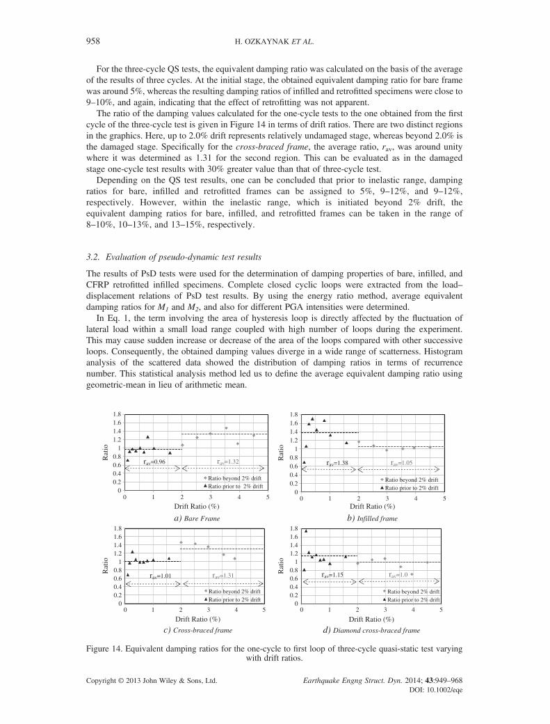
For the three-cycle QS tests, the equivalent damping ratio was calculated on the basis of the averageof the results of three cycles. At the initial stage, the obtained equivalent damping ratio for bare framewas around 5%, whereas the resulting damping ratios of infilled and retrofitted specimens were close to9–10%, and again, indicating that the effect of retrofitting was not apparent.
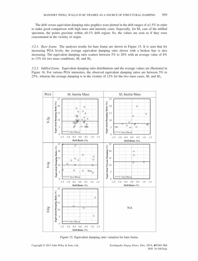
The ratio of the damping values calculated for the one-cycle tests to the one obtained from the firstcycle of the three-cycle test is given in Figure 14 in terms of drift ratios. There are two distinct regionsin the graphics. Here, up to 2.0% drift represents relatively undamaged stage, whereas beyond 2.0% isthe damaged stage. Specifically for the cross-braced frame, the average ratio, rav, was around unitywhere it was determined as 1.31 for the second region. This can be evaluated as in the damagedstage one-cycle test results with 30% greater value than that of three-cycle test.
Depending on the QS test results, one can be concluded that prior to inelastic range, dampingratios for bare, infilled and retrofitted frames can be assigned to 5%, 9–12%, and 9–12%,respectively. However, within the inelastic range, which is initiated beyond 2% drift, theequivalent damping ratios for bare, infilled, and retrofitted frames can be taken in the range of8–10%, 10–13%, and 13–15%, respectively.
3.2. Evaluation of pseudo-dynamic test results
The results of PsD tests were used for the determination of damping properties of bare, infilled, andCFRP retrofitted infilled specimens. Complete closed cyclic loops were extracted from the load–displacement relations of PsD test results. By using the energy ratio method, average equivalentdamping ratios for M1 and M2, and also for different PGA intensities were determined.
In Eq. 1, the term involving the area of hysteresis loop is directly affected by the fluctuation oflateral load within a small load range coupled with high number of loops during the experiment.This may cause sudden increase or decrease of the area of the loops compared with other successiveloops. Consequently, the obtained damping values diverge in a wide range of scatterness. Histogramanalysis of the scattered data showed the distribution of damping ratios in terms of recurrencenumber. This statistical analysis method led us to define the average equivalent damping ratio usinggeometric-mean in lieu of arithmetic mean.
00.20.40.60.8
11.21.41.61.8
0 1 2 3 4 5
Rat
io
Drift Ratio (%)
Ratio beyond 2% driftRatio prior to 2% drift
00.20.40.60.8
11.21.41.61.8
0 1 2 3 4 5
Rat
io
Drift Ratio (%)
Ratio beyond 2% driftRatio prior to 2% drift
a) Bare Frame b) Infilled frame
00.20.40.60.8
11.21.41.61.8
0 1 2 3 4 5
Rat
io
Drift Ratio (%)
Ratio beyond 2% drift
Ratio prior to 2% drift0
0.20.40.60.8
11.21.41.61.8
0 1 2 3 4 5
Rat
io
Drift Ratio (%)
Ratio beyond 2% drift
Ratio prior to 2% drift
c) Cross-braced frame d) Diamond cross-braced frame
rav=0.96 rav=1.32 rav=1.38 rav=1.05
rav=1.01 rav=1.31 rav=1.15 rav=1.0
Figure 14. Equivalent damping ratios for the one-cycle to first loop of three-cycle quasi-static test varyingwith drift ratios.
958 H. OZKAYNAK ET AL.
Copyright © 2013 John Wiley & Sons, Ltd. Earthquake Engng Struct. Dyn. 2014; 43:949–968DOI: 10.1002/eqe
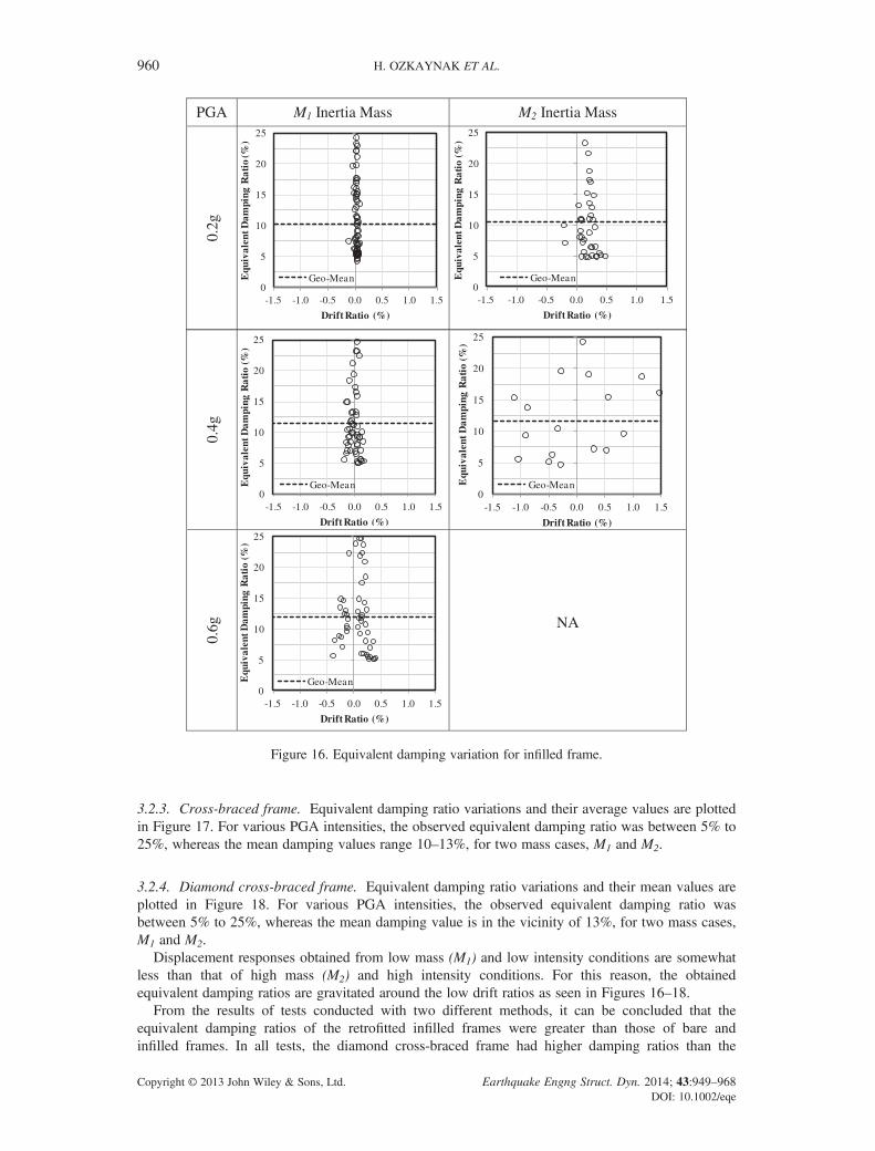
The drift versus equivalent damping ratio graphics were plotted in the drift ranges of ±1.5% in orderto make good comparison with high mass and intensity cases. Especially, for M1 case of the infilledspecimen, the points gravitate within ±0.1% drift region. So, the values are seen as if they wereconcentrated in the vicinity of origin.
3.2.1. Bare frame. The analyses results for bare frame are shown in Figure 15. It is seen that forincreasing PGA levels, the average equivalent damping ratio shown with a broken line is alsoincreasing. The equivalent damping ratio scatters between 5% to 20% with an average value of 8%to 13% for two mass conditions, M1 and M2.
3.2.2. Infilled frame. Equivalent damping ratio distributions and the average values are illustrated inFigure 16. For various PGA intensities, the observed equivalent damping ratios are between 5% to25%, whereas the average damping is in the vicinity of 12% for the two mass cases, M1 and M2.
Figure 15. Equivalent damping ratio variation for bare frame.
MASONRY INFILL WALLS IN RC FRAMES AS A SOURCE OF STRUCTURAL DAMPING 959
Copyright © 2013 John Wiley & Sons, Ltd. Earthquake Engng Struct. Dyn. 2014; 43:949–968DOI: 10.1002/eqe
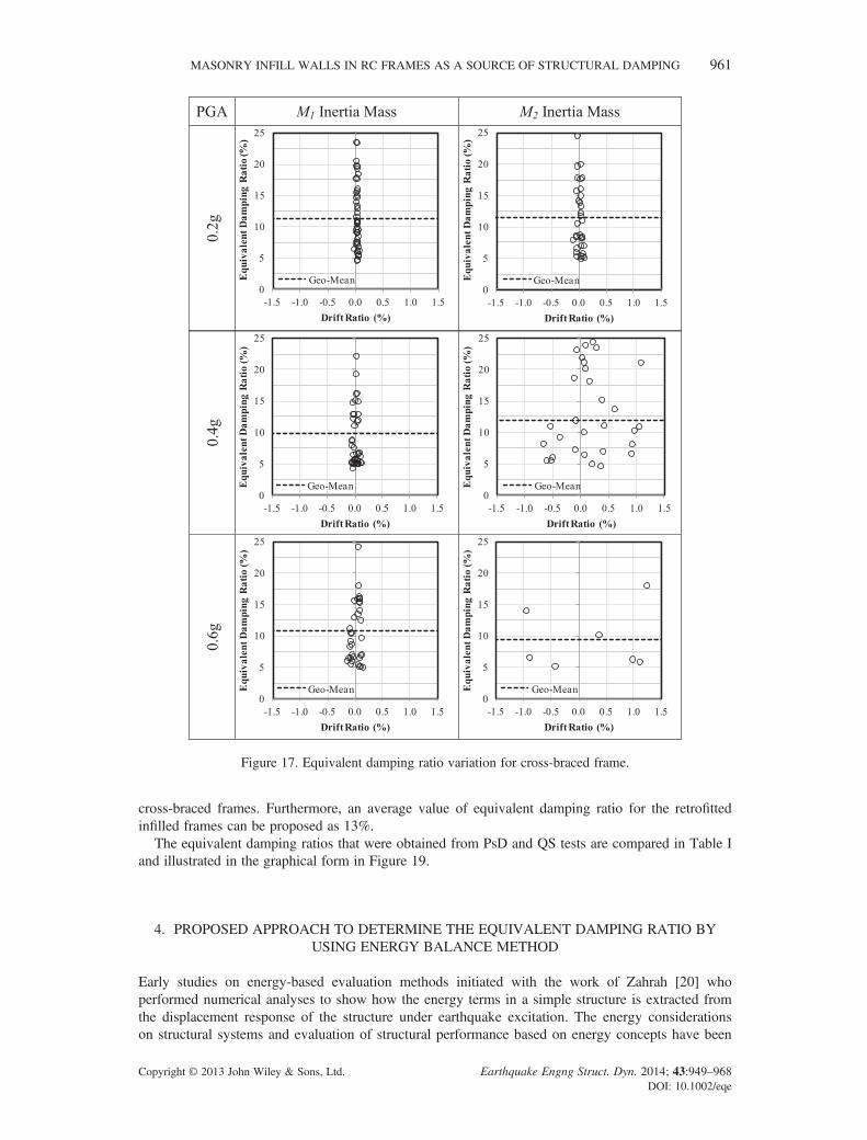
3.2.3. Cross-braced frame. Equivalent damping ratio variations and their average values are plottedin Figure 17. For various PGA intensities, the observed equivalent damping ratio was between 5% to25%, whereas the mean damping values range 10–13%, for two mass cases, M1 and M2.
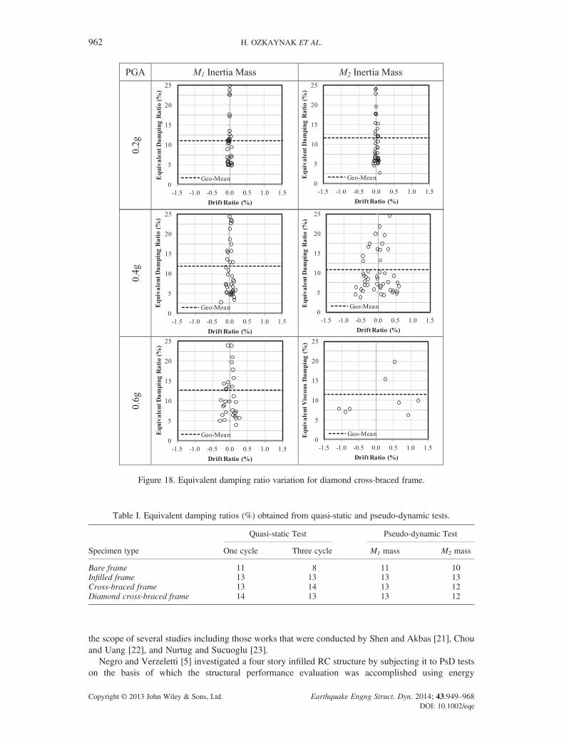
3.2.4. Diamond cross-braced frame. Equivalent damping ratio variations and their mean values areplotted in Figure 18. For various PGA intensities, the observed equivalent damping ratio wasbetween 5% to 25%, whereas the mean damping value is in the vicinity of 13%, for two mass cases,M1 and M2.
Displacement responses obtained from low mass (M1) and low intensity conditions are somewhatless than that of high mass (M2) and high intensity conditions. For this reason, the obtainedequivalent damping ratios are gravitated around the low drift ratios as seen in Figures 16–18.
From the results of tests conducted with two different methods, it can be concluded that theequivalent damping ratios of the retrofitted infilled frames were greater than those of bare andinfilled frames. In all tests, the diamond cross-braced frame had higher damping ratios than the
Figure 16. Equivalent damping variation for infilled frame.
960 H. OZKAYNAK ET AL.
Copyright © 2013 John Wiley & Sons, Ltd. Earthquake Engng Struct. Dyn. 2014; 43:949–968DOI: 10.1002/eqe
cross-braced frames. Furthermore, an average value of equivalent damping ratio for the retrofittedinfilled frames can be proposed as 13%.
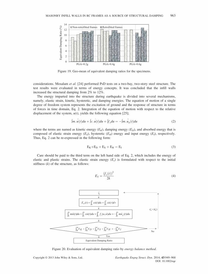
The equivalent damping ratios that were obtained from PsD and QS tests are compared in Table Iand illustrated in the graphical form in Figure 19.
4. PROPOSED APPROACH TO DETERMINE THE EQUIVALENT DAMPING RATIO BYUSING ENERGY BALANCE METHOD
Early studies on energy-based evaluation methods initiated with the work of Zahrah [20] whoperformed numerical analyses to show how the energy terms in a simple structure is extracted fromthe displacement response of the structure under earthquake excitation. The energy considerationson structural systems and evaluation of structural performance based on energy concepts have been
Figure 17. Equivalent damping ratio variation for cross-braced frame.
MASONRY INFILL WALLS IN RC FRAMES AS A SOURCE OF STRUCTURAL DAMPING 961
Copyright © 2013 John Wiley & Sons, Ltd. Earthquake Engng Struct. Dyn. 2014; 43:949–968DOI: 10.1002/eqe
the scope of several studies including those works that were conducted by Shen and Akbas [21], Chouand Uang [22], and Nurtug and Sucuoglu [23].
Negro and Verzeletti [5] investigated a four story infilled RC structure by subjecting it to PsD testson the basis of which the structural performance evaluation was accomplished using energy
Figure 18. Equivalent damping ratio variation for diamond cross-braced frame.
Table I. Equivalent damping ratios (%) obtained from quasi-static and pseudo-dynamic tests.
Specimen type
Quasi-static Test Pseudo-dynamic Test
One cycle Three cycle M1 mass M2 mass
Bare frame 11 8 11 10Infilled frame 13 13 13 13Cross-braced frame 13 14 13 12Diamond cross-braced frame 14 13 13 12
962 H. OZKAYNAK ET AL.
Copyright © 2013 John Wiley & Sons, Ltd. Earthquake Engng Struct. Dyn. 2014; 43:949–968DOI: 10.1002/eqe
considerations. Mosalam et al. [24] performed PsD tests on a two-bay, two-story steel structure. Thetest results were evaluated in terms of energy concepts. It was concluded that the infill wallsincreased the structural damping from 2% to 12%.
The energy imparted into the structure during earthquake is divided into several mechanisms,namely, elastic strain, kinetic, hysteretic, and damping energies. The equation of motion of a singledegree of freedom system represents the excitation of ground and the response of structure in termsof forces in time domain, Eq. 2. Integration of the equation of motion with respect to the relativedisplacement of the system, u(t), yields the following equation [25];
∫m: u tð Þduþ ∫c: u tð Þduþ ∫f sdu ¼ �∫m: ug tð Þdu (2)
where the terms are named as kinetic energy (EK), damping energy (ED), and absorbed energy that iscomposed of elastic strain energy (ES), hysteretic (EH) energy and input energy (EI), respectively.Thus, Eq. 2 can be re-expressed in the following form:
EKþED þ ES þ EH ¼ EI (3)
Care should be paid to the third term on the left hand side of Eq. 2, which includes the energy ofelastic and plastic strains. The elastic strain energy (Es) is formulated with respect to the initialstiffness (k) of the structure, as follows:
ES ¼ f s tð Þð Þ22k
(4)
Figure 19. Geo-mean of equivalent damping ratios for the specimens.
Figure 20. Evaluation of equivalent damping ratio by energy balance method.
MASONRY INFILL WALLS IN RC FRAMES AS A SOURCE OF STRUCTURAL DAMPING 963
Copyright © 2013 John Wiley & Sons, Ltd. Earthquake Engng Struct. Dyn. 2014; 43:949–968DOI: 10.1002/eqe
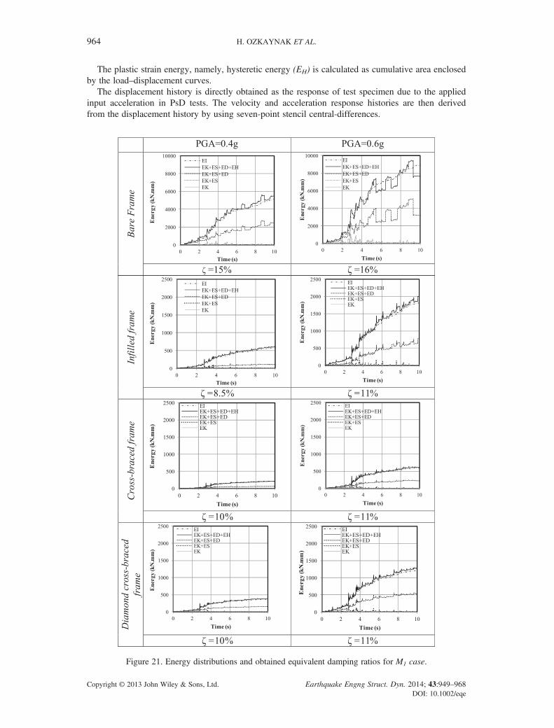
The plastic strain energy, namely, hysteretic energy (EH) is calculated as cumulative area enclosedby the load–displacement curves.
The displacement history is directly obtained as the response of test specimen due to the appliedinput acceleration in PsD tests. The velocity and acceleration response histories are then derivedfrom the displacement history by using seven-point stencil central-differences.
Figure 21. Energy distributions and obtained equivalent damping ratios for M1 case.
964 H. OZKAYNAK ET AL.
Copyright © 2013 John Wiley & Sons, Ltd. Earthquake Engng Struct. Dyn. 2014; 43:949–968DOI: 10.1002/eqe
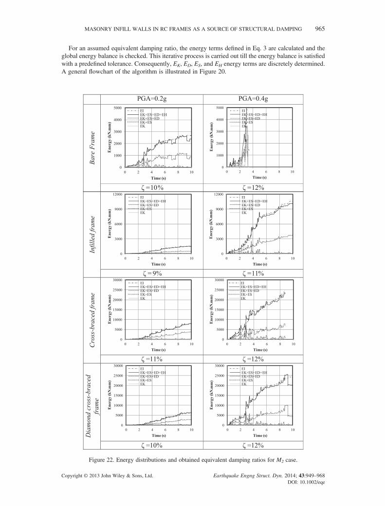
For an assumed equivalent damping ratio, the energy terms defined in Eq. 3 are calculated and theglobal energy balance is checked. This iterative process is carried out till the energy balance is satisfiedwith a predefined tolerance. Consequently, EK, ED, ES, and EH energy terms are discretely determined.A general flowchart of the algorithm is illustrated in Figure 20.
Figure 22. Energy distributions and obtained equivalent damping ratios for M2 case.
MASONRY INFILL WALLS IN RC FRAMES AS A SOURCE OF STRUCTURAL DAMPING 965
Copyright © 2013 John Wiley & Sons, Ltd. Earthquake Engng Struct. Dyn. 2014; 43:949–968DOI: 10.1002/eqe
The well-known relation given in Eq. 5 is used to calculate the damping coefficient c as a basis forthis iterative scheme.
c ¼ 2ζmω (5)
The proposed energy balance methodology was carried out to PsD tests for M1 and M2 cases andacceleration intensities of 0.2, 0.4, and 0.6 g. The energy distribution graphics and the obtainedequivalent damping ratios are presented in Figures 21 and 22 for M1 and M2 cases, respectively.
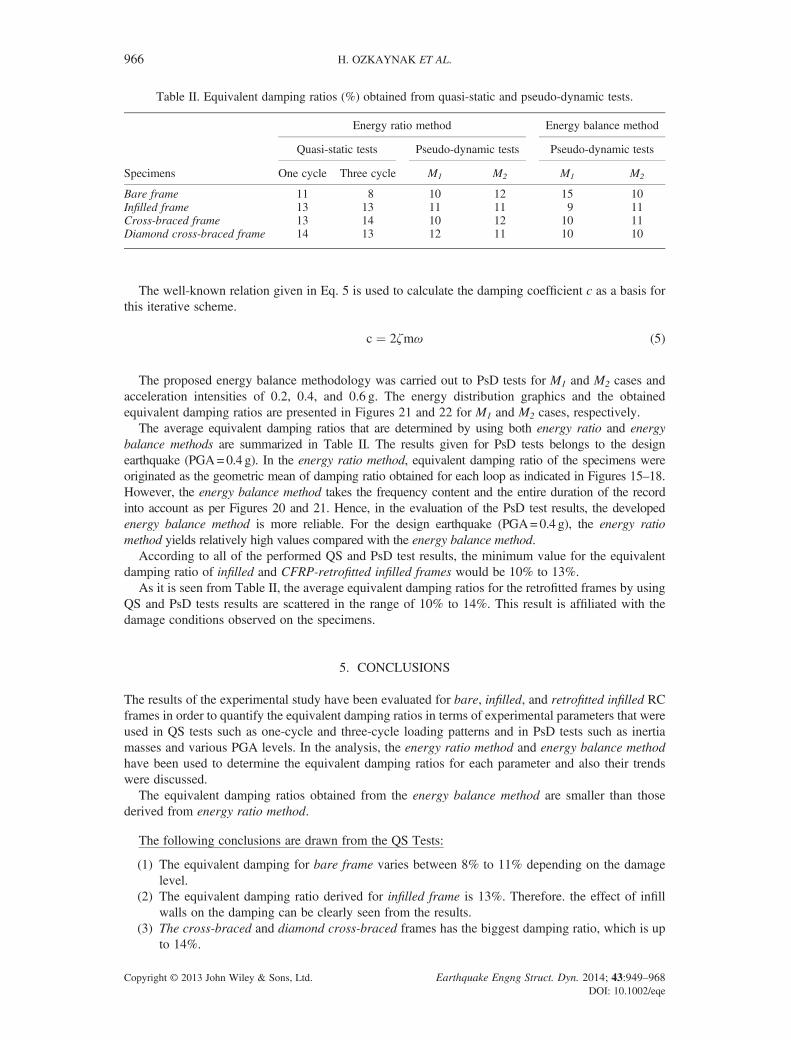
The average equivalent damping ratios that are determined by using both energy ratio and energybalance methods are summarized in Table II. The results given for PsD tests belongs to the designearthquake (PGA=0.4 g). In the energy ratio method, equivalent damping ratio of the specimens wereoriginated as the geometric mean of damping ratio obtained for each loop as indicated in Figures 15–18.However, the energy balance method takes the frequency content and the entire duration of the recordinto account as per Figures 20 and 21. Hence, in the evaluation of the PsD test results, the developedenergy balance method is more reliable. For the design earthquake (PGA=0.4 g), the energy ratiomethod yields relatively high values compared with the energy balance method.
According to all of the performed QS and PsD test results, the minimum value for the equivalentdamping ratio of infilled and CFRP-retrofitted infilled frames would be 10% to 13%.
As it is seen from Table II, the average equivalent damping ratios for the retrofitted frames by usingQS and PsD tests results are scattered in the range of 10% to 14%. This result is affiliated with thedamage conditions observed on the specimens.
5. CONCLUSIONS
The results of the experimental study have been evaluated for bare, infilled, and retrofitted infilled RCframes in order to quantify the equivalent damping ratios in terms of experimental parameters that wereused in QS tests such as one-cycle and three-cycle loading patterns and in PsD tests such as inertiamasses and various PGA levels. In the analysis, the energy ratio method and energy balance methodhave been used to determine the equivalent damping ratios for each parameter and also their trendswere discussed.
The equivalent damping ratios obtained from the energy balance method are smaller than thosederived from energy ratio method.
The following conclusions are drawn from the QS Tests:
(1) The equivalent damping for bare frame varies between 8% to 11% depending on the damagelevel.
(2) The equivalent damping ratio derived for infilled frame is 13%. Therefore. the effect of infillwalls on the damping can be clearly seen from the results.
(3) The cross-braced and diamond cross-braced frames has the biggest damping ratio, which is upto 14%.
Table II. Equivalent damping ratios (%) obtained from quasi-static and pseudo-dynamic tests.
Specimens
Energy ratio method Energy balance method
Quasi-static tests Pseudo-dynamic tests Pseudo-dynamic tests
One cycle Three cycle M1 M2 M1 M2
Bare frame 11 8 10 12 15 10Infilled frame 13 13 11 11 9 11Cross-braced frame 13 14 10 12 10 11Diamond cross-braced frame 14 13 12 11 10 10
966 H. OZKAYNAK ET AL.
Copyright © 2013 John Wiley & Sons, Ltd. Earthquake Engng Struct. Dyn. 2014; 43:949–968DOI: 10.1002/eqe
The following conclusions are drawn for the PsD Tests:
(1) In the comparison made for the design earthquake (PGA=0.4 g), equivalent damping ratios ofall the specimens are in the range of 10–15%. The value for bare frame accounts for the largehysteretic cycles prior to the collapse.
(2) The equivalent damping ratio for infilled frame is obtained in the range of 9% to 11%. Thisresult is consistent with the existing literature.
(3) The average damping characteristics of the retrofitted frames are scattered in the range of 10% to14% for the altered mass and PGA intensities. Although bare frame failed during the designearthquake (PGA= 0.4 g), both types of the retrofitted frames could withstand at the end ofthe earthquake of PGA= 0.6 g. So, for the retrofitted frames equivalent damping ratio turnsout to be sustainable through the seismic action.
On the basis of the overall evaluation, equivalent damping ratio of 10–13% is recommended as asustainable range for the CFRP retrofitted RC frames.
ACKNOWLEDGEMENTS
This study was conducted at Structural and Earthquake Engineering Laboratory of Istanbul TechnicalUniversity. It was sponsored by research projects 106M050 of Scientific and Technological Research Councilof Turkey (TUBITAK) and 31966 of Istanbul Technical University (ITU) Research Funds. The contributionsof MSc H. Saruhan, E. S. Tako, and I. Bastemir to the experimental works are gratefully acknowledged.
REFERENCES
1. Dolsek M, Fajfar P. The effects of masonry infills on the seismic response of a four-storey reinforced concrete framea deterministic assessment. Engineering Structures 2008; 30:1991–2001.
2. Buttmann P. Experimental determination of damping factors for walls of masonry and reinforced concrete. Transac-tions of 7th International Conference on Structural Mechanics in Reactor Technology, 1983.
3. Farrar CR, Baker WE. Damping in low aspect ratio reinforced concrete shear walls. Earthquake Engineering andStructural Dynamics 1995; 24(3):439–455.
4. Fardis MN, Panagiotakos TB. Seismic design and response of bare and masonry-infilled reinforced concrete build-ings, part II, infilled structures. Journal of Earthquake Engineering 1997; 1(3):475–503.
5. Negro P, Verzeletti G. Effect of infill on the global behavior of R/C frames: energy considerations from pseudo-dynamic tests. Earthquake Engineering and Structural Dynamics 1996; 25(8):753–773.
6. Hashemi A, Mosalam KM. Shake table experiment on reinforced concrete structure containing masonry infill wall.Earthquake Engineering and Structural Dynamics 2006; 35(14):1827–1852.
7. Hashemi A, Mosalam KM. Seismic evaluation of reinforced concrete buildings including effects of masonry infillwalls. PEER Technical Report 2007/100, 2007.
8. Costa A, Arêde A, Costa A, Oliveira CS. In situ cyclic tests on existing stone masonry walls and strengtheningsolutions. Earthquake Engineering and Structural Dynamics 2011; 40(4):449–471.
9. Sofronie R. Performances in seismic strengthening of masonry. 13th World Conference on Earthquake Engineering,Vancouver, 2004.
10. Santa-Maria H, Duarte G, Garib A. Experimental investigation of masonry panels externally strengthened with CFRPlaminates and fabric subjected to in-plane shear load. 13th World Conference on Earthquake Engineering, Vancouver,2004.
11. Elgawady MA, Lestuzzi P, Badoux M. Static cyclic response of masonry walls retrofitted with fiber-reinforcedpolymers. Journal of Composites for Construction 2007; 11(1):50–61.
12. Turkish Earthquake Resistant Design Code. Ministry of Public Works and Settlement: Ankara, 2007.13. ASTM E519 – 02. Standard test method for diagonal tension (shear) in masonry assemblages. An American National
Standard, 2002.14. Ozsayın B, Yılmaz E, Ispir M, Ozkaynak H, Yüksel E, İlki A. Characteristics of CFRP retrofitted hollow brick walls
of reinforced concrete frames. Construction and Building Materials, 2011; 25(10):4017–4024.15. Oasys Sigraph. A program for Generation, Manipulation and Graphical Display of Tabular X-Y Data. Oasys Ltd.,
Newcastle-Upon-Tyne, UK, 2006.16. Kuwamura H; Kirino Y, Akiyama H. Prediction of earthquake energy input from smoothed Fourier amplitude.
Earthquake Engineering and Structural Dynamics 1994; 23(10):1125–1137.17. Özkaynak H. The earthquake behavior of RC frames with fiber polymer confined infill walls and their structural
damping properties. Ph.D. Thesis, Istanbul Technical University, Istanbul, 2010, (in Turkish).18. Özkaynak H, Yüksel E, Büyüköztürk O, Yalçın C, Dindar AA. Quasi-static and pseudo-dynamic testing of infilled
RC frames retrofitted with CFRP material. Composites: Part B 2011; 42(2):238–263.19. Chopra AK.Dynamics of Structures Theory and Applications to Earthquake Engineering. Prentice Hall: Englewood, 2001.
MASONRY INFILL WALLS IN RC FRAMES AS A SOURCE OF STRUCTURAL DAMPING 967
Copyright © 2013 John Wiley & Sons, Ltd. Earthquake Engng Struct. Dyn. 2014; 43:949–968DOI: 10.1002/eqe

20. Zahrah TF. Seismic energy absorption in simple structures. Ph.D. Thesis, University of Illinois at Urbana-Champaign,Illinois, 1982.
21. Shen J, Akbas B. Seismic energy demand in steel moment frames. Journal of Earthquake Engineering 1999; 3(4):519–559.22. Chou CC, Uang CM. An evaluation of seismic energy demand: an attenuation approach. PEER Report 2000/04,
Pacific Earthquake Engineering Research Center, 2000.23. Nurtug A, Sucuoglu H. Prediction of seismic energy dissipation in SDOF System. Earthquake Engineering and
Structural Dynamics 1995; 24(9):1215–1223.24. Mosalam KM, White RN, Ayala G. Response of infilled frames using pseudo-dynamic experimentation. Earthquake
Engineering and Structural Dynamics 1998; 27(6):589–608.25. Uang CM, Bertero VV. Evaluation of seismic energy in structures. Earthquake Engineering and Structural Dynamics
1990; 19:77–90.
968 H. OZKAYNAK ET AL.
Copyright © 2013 John Wiley & Sons, Ltd. Earthquake Engng Struct. Dyn. 2014; 43:949–968DOI: 10.1002/eqe