massachusetts simple-septic® design and installation manual
TRANSCRIPT

The Presby Wastewater Treatment System
Massachusetts Simple-Septic®
Design and Installation Manual
Minimizes the Expense Protects the Environment Preserves the Site
Presby Environmental, Inc. The Next Generation of Wastewater Treatment Technology
143 Airport Road, Whitefield, NH 03598
Tel: 800-473-5298 Fax: 603-837-9864 [email protected]
www.PresbyEnvironmental.com © Copyright April 2014, Presby Environmental, Inc., All Rights Reserved

SS Design & Installation Manual for MA, © Presby Environmental, Inc. April 2014 Edition - i-
The information in this manual is subject to change without notice. We recommend that you check your state’s page on our website on a regular basis for updated information. Your suggestions and comments are welcome. Please contact us at: 800-473-5298
Presby Environmental, Inc. 143 Airport Road
Whitefield, NH 03598 Phone: 1-800-473-5298 Fax: (603) 837-9864
Website: www.PresbyEnvironmental.com
Presby Environmental, Inc. United States and Canadian Patents: Coupling system: US Patent No 6,899,359; Canada 2,359,255 End Cap: US Patent No 6,792,977; Canada 2,365,453 Enviro-Septic US Patent No 6,461,078; Canada 2,300,535 Fluid Conduit (AES): US Patent No 8,342,212; Canada 2,609,409 Multi-Layer Fabric (AES): US Patent No 5,954,451; Canada 2,185,087 Multi-Level Leaching System: US Patent No 6,290,429; Canada 2,286,995 Pipe Making Method: US Patent No 5,606,786; Canada 2,817,126 Skimmer Tab Former: US Patent No 7,270,532; Canada 2,415,194 US Patent Nos. 7,713,414, 6,461,078; Canada 2,300,535 With other patents pending in the United States, Canada and other jurisdictions.
Advanced Enviro-Septic® is a registered trademark of Presby Environmental Inc.
Enviro-Septic® is a registered trademark of Presby Environmental, Inc. Simple-Septic® is a registered trademark of Presby Environmental Inc.
IMPORTANT NOTICE: This Manual is intended ONLY for use in designing and installing Presby Environmental’s Advanced Enviro-Septic®, Enviro-Septic® and Simple-Septic® Wastewater Treatment
Systems. The use of this Manual with any other product is prohibited. The processes and design criteria contained herein are based solely on our experience with and testing of Advanced Enviro-Septic®, Enviro-
Septic® and Simple-Septic®. Substitution of any other large diameter gravelless pipe will result in compromised treatment of wastewater and other adverse effects
© Presby Environmental, Inc. April 2014 All Rights Reserved
Date of Issue: April 2014

SS Design & Installation Manual for MA, © Presby Environmental, Inc. April 2014 Edition - ii-
TABLE OF CONTENTS
Section Number Page Number 1.0 Background ....................................................................................................................................... 1
2.0 Eight Stages of Wastewater Treatment for Simple-Septic® Systems .............................................. 2
3.0 Simple-Septic® Components ............................................................................................................ 3
4.0 Introduction ........................................................................................................................................ 3
5.0 General Design Criteria ..................................................................................................................... 4
6.0 Percolation Rates 1-60 MPI Design Considerations ......................................................................... 8
7.0 Basic Serial Distribution Layout ........................................................................................................ 9
8.0 D-Box Distribution ............................................................................................................................. 9
9.0 Combination Serial Distribution ....................................................................................................... 10
10.0 In-Ground Bed Systems .................................................................................................................. 11
11.0 Elevated Bed Systems (Mounds) .................................................................................................... 11
12.0 Non-Conventional System Configurations (1-60 MPI) .................................................................... 11
13.0 Table A: Simple-Septic® Pipe Required (1 – 60 MPI) ..................................................................... 12
14.0 Table B: Long Term Acceptance Rate (LTAR) ............................................................................... 12
15.0 Table C: System Sand Bed Area .................................................................................................... 13
16.0 Table D: Number of Rows and Pipe Layout Width ......................................................................... 13
17.0 Design Procedure (1 – 60 MPI) ....................................................................................................... 14
18.0 Design & Sizing Criteria for Percolation Rates (61–90 MPI) .......................................................... 15
19.0 Simple-Septic® Pipe Requirement (61-90 MPI) ............................................................................. 15
20.0 Table E: Allowable System Slope (61-90 MPI) ............................................................................... 15
21.0 Table F: System Sand Bed Area (61-90 MPI) ................................................................................ 15
22.0 Table G: Row Length Minimum (61-90 MPI) .................................................................................. 15
23.0 Centered Rows - Level Systems (61-90 MPI) ................................................................................. 15
24.0 Grouped Rows - Sloping Systems (61-90 MPI) .............................................................................. 16
25.0 Design Procedure (61 – 90 MPI) ..................................................................................................... 17
26.0 Pumped System Requirements ...................................................................................................... 18
27.0 Venting Requirements ..................................................................................................................... 18
28.0 Site Selection .................................................................................................................................. 21
29.0 Installation Requirements, Component Handling and Site Preparation.......................................... 21
30.0 System Bacteria Rejuvenation and Expansion ............................................................................... 23
31.0 Operation & Maintenance ............................................................................................................... 24
32.0 Glossary .......................................................................................................................................... 24
33.0 Massachusetts Simple-Septic® System Installation Form ............................................................. 28

SS Design & Installation Manual for MA, © Presby Environmental, Inc. April 2014 Edition -1-
1.0 Background Liquid that exits from a septic tank (“effluent”) contains suspended solids that can cause traditional systems to fail prematurely. Solids can overload bacteria, cut off air required for aerobic bacterial activity, and/or seal the underlying soil, interfering with its ability to absorb liquid. 1.1 What Our System Does By utilizing simple yet effective natural processes, the Simple-Septic® (SS) Treatment System treats septic tank effluent in a manner that prevents suspended solids from sealing the underlying soil, increases system aeration, and provides a greater bacterial treatment area (“biomat”) than traditional systems. 1.2 Why Our System Excels The Simple-Septic® Treatment System retains solids in its pipe and provides multiple bacterial surfaces to treat effluent prior to its contact with the soil. The continual cycling of effluent (the rising and falling of liquid inside the pipe) enhances bacterial growth. This all combines to create a unique eco-system that no other passive wastewater treatment system is designed to offer. The result is a system that excels by being more efficient, last longer, and have a minimal environmental impact. 1.3 System Advantages
a) costs less than traditional systems b) eliminates the need for washed stone c) often requires a smaller area d) installs more easily and quickly than traditional systems e) adapts easily to residential and commercial sites of virtually any size f) adapts well to difficult sites g) develops a protected receiving surface preventing sealing of the underlying soil h) blends “septic mounds” into sloping terrain i) increases system performance and longevity j) tests environmentally safer than traditional systems k) recharges groundwater more safely than traditional systems l) made from recycled plastic
1.4 Patented Simple-Septic® Technology The Simple-Septic® (SS) pipes are an onsite wastewater treatment system consisting of a patented configuration of ridged, corrugated, perforated plastic pipe with interior skimmer tabs, surrounded by a geo-textile fabric. The Simple-Septic® pipes are assembled and installed in a bed of specified System Sand which can either be below the ground or above. The system is designed to simultaneously purify and disperse effluent after primary treatment by a septic tank. The system is completely passive, requiring no electricity, motors, alarms, computers, etc.
SS Design & Installation Manual for MA, © Presby Environmental, Inc. April 2014 Edition - 2-
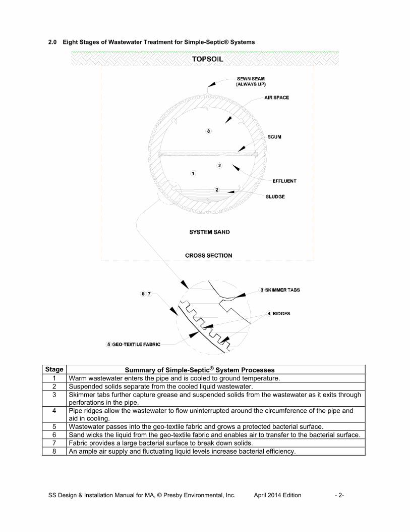
2.0 Eight Stages of Wastewater Treatment for Simple-Septic® Systems
Stage Summary of Simple-Septic® System Processes
1 Warm wastewater enters the pipe and is cooled to ground temperature. 2 Suspended solids separate from the cooled liquid wastewater. 3 Skimmer tabs further capture grease and suspended solids from the wastewater as it exits through
perforations in the pipe. 4 Pipe ridges allow the wastewater to flow uninterrupted around the circumference of the pipe and
aid in cooling. 5 Wastewater passes into the geo-textile fabric and grows a protected bacterial surface. 6 Sand wicks the liquid from the geo-textile fabric and enables air to transfer to the bacterial surface. 7 Fabric provides a large bacterial surface to break down solids. 8 An ample air supply and fluctuating liquid levels increase bacterial efficiency.

SS Design & Installation Manual for MA, © Presby Environmental, Inc. April 2014 Edition - 3-
SLOPING BED
2"-4" LEVEL
OFFSETADAPTER
4"DIA. RAISED CONNECTION BETWEEN ROWS
LEVEL BED
3.0 Simple-Septic® Components 3.1 Simple-Septic® Pipe
a) Plastic pipe made with a significant percentage of recycled material b) 10 ft. sections (can be cut to any length) c) Ridged and perforated, with skimmer tabs on interior d) Wrapped in a non-woven geo-textile fabric stitched in place e) Exterior diameter of 12 in. f) Each 10 ft. section has a liquid holding capacity of approx. 58 gallons g) A 10 ft. length of SS is flexible enough to bend up to 90°
3.2 Offset Adapter and Double Offset Adapter An offset adapter is a plastic fitting 12 in. in diameter with an inlet hole designed to accept a 4 inch sewer line, raised connection or vent pipe. The hole is to be installed in the 12 o’clock position. The distance from the bottom of the Offset Adapter to the bottom of its inlet hole is 7 in. When assembling pipes into rows, note that the geo-textile fabrics are placed over the edges of the Offset Adapter and Couplings. The Double Offset Adapter has two 4 in. holes. The hole in the 6 o'clock position is designed to accept a bottom drain. 3.3 Coupling A coupling is a plastic fitting used to create a connection between two pieces of SS pipe. Note that the couplings are wide enough to cover 1 or 2 pipe corrugations on each of the two pipe ends being joined. The couplings feature a snap-lock feature that requires no tools. When assembling pipes into rows, note that the geo-textile fabric does not go under couplings. Pull fabric back, install coupling, and then pull fabric over coupling. Also note that during installation in cold weather, couplings are easier to work with if stored in a heated location (such as a truck cab) before use. 3.4 Raised Connection A raised connection is a PVC Sewer & Drain pipe configuration which is used to connect SS rows. Raised connections extend 2 in. to 4 in. into pipe and are installed on an angle (as shown below). All PVC joints should be glued.
4.0 Introduction
4.1 Presby Environmental Standards All SS systems must be designed and installed in compliance with the procedures and specifications described in this Manual and in the product’s Massachusetts approval. 4.2 Massachusetts Rules This Manual is to be used in conjunction with the current State of Massachusetts Department of Environmental Protection Rules, 310 CMR 15. 4.3 Conflicts between Massachusetts Rules & Manual In the event of contradictions between this Manual and Massachusetts Department of Environmental Protection regulations, Presby Environmental, Inc. should be contacted for technical assistance. Exceptions to any Massachusetts rules other than those specifically discussed in this Manual require a DEP waiver. Please contact us for technical assistance at (800) 473-5298. 4.4 Certification Requirements Certification classes are required for designers and installers wishing to use Presby Environmental, Inc.’s Simple-Septic® product. Certification is obtained by attending a Certification Course presented by Presby Environmental, Inc. or its sanctioned representative. Certification can also be obtained by viewing tutorial videos on our website (high speed connection required) and then successfully passing a short assessment test, which is also available over the internet. It is recommended that all professionals involved in the inspection, review or certification of SS systems become Presby Certified.

SS Design & Installation Manual for MA, © Presby Environmental, Inc. April 2014 Edition - 4-
PRESBY PIPE TYP.
VENT MANIFOLD
BOTTOM DRAIN SUMP
4"Ø BOTTOM DRAIN MANIFOLD
VENT
LOCK OR BOLT COVER CLOSED
BOTTOM DRAIN CONNECTED TO SIX O'CLOCK POSITION OF DOUBLE OFFSET ADAPTER AT THE END OF EACH SERIAL SECTION. THE VENT MANIFOLD IS ATTACHED TO THE TWELVE O'CLOCK
POSITION OF THE DOUBLE OFFSET ADAPTER (OVER EACH BOTTOM DRAIN CONNECTION).
DBOX (FARSIDE) TO DBOX (FARSIDE)18"
4.5 Technical Support Presby Environmental, Inc. provides technical support to all individuals using our products. For questions about our products or the information contained in this Manual, or to register for a Certification Course, please contact us at 1-800-473-5298. 5.0 General Design Criteria
5.1 Barrier Materials Over System Sand No barrier materials (hay, straw, tarps, etc.) are required to be placed between the System Sand and cover material, unless the field is being designed for H-20 loading where stabilization fabric is used (see sect. 5.14, page 5 ). 5.1 Breakout Elevation Breakout Elevation is defined as the elevation 6 inches below the Simple-Septic® rows for all percolation rates (see ill. in sect. 6.3, page 8). 5.2 Bottom Drain A bottom drain is a line connected to the hole in the 6 o’clock position of a double offset adapter at the end of each serial section or each row in a D-Box Distribution Configuration which drains to a sump and is utilized to lower the water level in a saturated system or to facilitate system rejuvenation. 5.3 Center-to-Center Spacing The required minimum Center-to-Center pipe spacing is 1.5 ft. for 1-61 MPI and 3 ft. for 61-90 MPI. 5.4 Converging Flows Restriction SS Systems must not be located where surface or ground waters will converge, causing surface water flow to become concentrated or restricted within the soil absorption field (see Site Selection details in sect. 28.0, page 21). 5.5 Daily Design Flow per Bedroom Bedrooms are calculated at a daily design flow of 110 GPD each. Fields that service more than two residential units should use the commercial loading section of all sizing tables in this manual. 5.6 Daily Design Flow The minimum daily design flow for any single-family residential system on its own lot is two bedrooms (220 GPD) and 300 GPD for any commercial system.
a) Certain fixtures, such as jetted tubs, may require an increase in the size of the septic tank. b) Daily design flow for a single bedroom apartment with a kitchen connected to a residence (also
sometimes referred to as a “studio” or “in-law apartment”) shall be calculated by adding two additional bedrooms (220 GPD).
c) When daily design flow is determined by water meter use for commercial systems, refer to DEP Rules. d) PEI recommends taking the average daily use from a peak month and multiply it by a peaking factor of
(2) times minimum. e) Note that “daily design flows” are calculated to assume occasional “peak” usage and a factor of safety;
Systems are not expected to receive continuous dosing at full daily design load. 5.7 Distribution Box (D-Box) A distribution box is a device used to divide effluent flow to more than one portion of a Presby Field. A D-Box is required for all Presby Systems and cannot be used as a substitute for the Inspection Port. 5.8 Distribution Box Manifold A D-Box manifold is utilized to evenly divide flow to more than one field and is especially useful when designing for large daily design flows. Flow Equalizers are required on all used D-Box outlets.
INLET
OUTLET
D-BOX
OUTLET
UNUSEDOUTLET
4" Ø PVCTYPICAL
NOTE: UTILIZING EVERY OTHEROUTLET WILL PROVIDE ROOM FORREQUIRED PIPING AND ALLOWFOR EASIER INSTALLATION
SS Design & Installation Manual for MA, © Presby Environmental, Inc. April 2014 Edition - 5-
AES PIPE
INSTALL STABILIZATION FABRIC WITH A GRAB TENSILE STRENGTH OF 315 LBS PER ASTM D 4632" SIX INCHES OVER AES PIPE
EXTEND FABRIC 3' MIN BEYOND EDGE OF PIPE (ALL EDGES)
BANK RUN GRAVEL(NO STONES OVER 2"Ø)
PAVEMENT
12" MIN (BELOW PAVEMENT)
6" SYSTEM SAND
VENT MAINIFOLD
NO SAND VOIDS ALLOWED. WALK BETWEEN ROWS (COMPRESSING SAND) TO ENSURE SAND
FILLS ALL VOIDS AROUND AES PIPES.
BOTTOM DRAINS RECOMMENDED WHEN AES PIPE ENDS ARE INACCESSIBLE
VE
NT
ST
AC
K
SLOPE
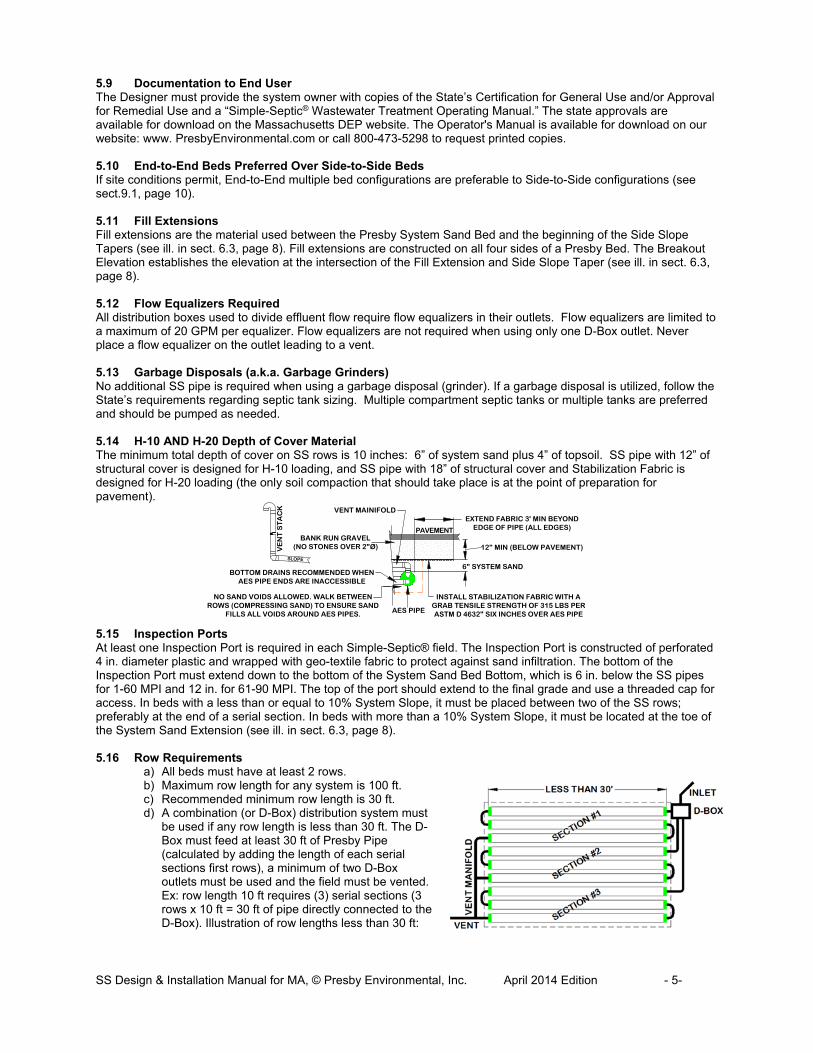
5.9 Documentation to End User The Designer must provide the system owner with copies of the State’s Certification for General Use and/or Approval for Remedial Use and a “Simple-Septic® Wastewater Treatment Operating Manual.” The state approvals are available for download on the Massachusetts DEP website. The Operator's Manual is available for download on our website: www. PresbyEnvironmental.com or call 800-473-5298 to request printed copies. 5.10 End-to-End Beds Preferred Over Side-to-Side Beds If site conditions permit, End-to-End multiple bed configurations are preferable to Side-to-Side configurations (see sect.9.1, page 10). 5.11 Fill Extensions Fill extensions are the material used between the Presby System Sand Bed and the beginning of the Side Slope Tapers (see ill. in sect. 6.3, page 8). Fill extensions are constructed on all four sides of a Presby Bed. The Breakout Elevation establishes the elevation at the intersection of the Fill Extension and Side Slope Taper (see ill. in sect. 6.3, page 8). 5.12 Flow Equalizers Required All distribution boxes used to divide effluent flow require flow equalizers in their outlets. Flow equalizers are limited to a maximum of 20 GPM per equalizer. Flow equalizers are not required when using only one D-Box outlet. Never place a flow equalizer on the outlet leading to a vent. 5.13 Garbage Disposals (a.k.a. Garbage Grinders) No additional SS pipe is required when using a garbage disposal (grinder). If a garbage disposal is utilized, follow the State’s requirements regarding septic tank sizing. Multiple compartment septic tanks or multiple tanks are preferred and should be pumped as needed. 5.14 H-10 AND H-20 Depth of Cover Material The minimum total depth of cover on SS rows is 10 inches: 6” of system sand plus 4” of topsoil. SS pipe with 12” of structural cover is designed for H-10 loading, and SS pipe with 18” of structural cover and Stabilization Fabric is designed for H-20 loading (the only soil compaction that should take place is at the point of preparation for pavement). 5.15 Inspection Ports At least one Inspection Port is required in each Simple-Septic® field. The Inspection Port is constructed of perforated 4 in. diameter plastic and wrapped with geo-textile fabric to protect against sand infiltration. The bottom of the Inspection Port must extend down to the bottom of the System Sand Bed Bottom, which is 6 in. below the SS pipes for 1-60 MPI and 12 in. for 61-90 MPI. The top of the port should extend to the final grade and use a threaded cap for access. In beds with a less than or equal to 10% System Slope, it must be placed between two of the SS rows; preferably at the end of a serial section. In beds with more than a 10% System Slope, it must be located at the toe of the System Sand Extension (see ill. in sect. 6.3, page 8). 5.16 Row Requirements
a) All beds must have at least 2 rows. b) Maximum row length for any system is 100 ft. c) Recommended minimum row length is 30 ft. d) A combination (or D-Box) distribution system must
be used if any row length is less than 30 ft. The D-Box must feed at least 30 ft of Presby Pipe (calculated by adding the length of each serial sections first rows), a minimum of two D-Box outlets must be used and the field must be vented. Ex: row length 10 ft requires (3) serial sections (3 rows x 10 ft = 30 ft of pipe directly connected to the D-Box). Illustration of row lengths less than 30 ft:

SS Design & Installation Manual for MA, © Presby Environmental, Inc. April 2014 Edition - 6-
4" PVC
2" MIN.
D-BOX
LEVEL
MAXIMUM LIQUID LEVEL
HIGHER THAN MAX. LIQUID LEVEL IN PIPE
2" - 4"
e) Row Center-to-Center Spacing is 1.5 ft min. for all systems in 0-60 mpi soils, and 3.0 ft min. in 61-90 mpi soils.
f) Rows shall be grouped in the middle of the sand bed area when System Sand Extensions are required. g) All rows must be laid level to within +/- ½ in. (total of 1 in.) of the specified elevation and preferably
parallel to the contour of the site, although alternate orientations are allowed with proper construction. Contact Technical Support for recommendations.
h) It is easier if row lengths are designed in exact 10 ft increments since Presby Pipe comes in 10 ft sections. However, if necessary, the pipe is easily cut to any length to meet site constraints.
5.17 Minimum Dispersal Area To meet Massachusetts’ requirements, at no time may a Simple-Septic® system be designed to have a sand bed area less than 40% of a conventional Title 5 aggregate system designed in accordance with 310 CMR 15.00 for the same site. 5.18 Pressure Distribution
a) The use of pressure distribution with SS Systems is not permitted. b) Pump systems to gain elevation are allowed (see Pump System Requirements, sect. 26.0, page 18).
5.19 Row Elevations for Sloping Sites Elevations must be provided on the construction drawing for each Simple-Septic® row in the sloping bed system. 5.20 Row Orientation SS rows must be laid level to within +/- ½ in. of the specified elevation and preferably should be parallel to the contour of the site. The minimum center-to-center spacing is determined by the percolation rate and system slope. The center-to-center spacing may be larger, but not less than the minimum requirement. 5.21 Separation Distances (Vertical and Horizontal) Vertical and horizontal separation distances are measured from the outermost edge(s) of the System Sand Bed. The local approving authority may allow the following reductions for remedial use without granting a waiver under 310 CMR 15.400 or obtaining MA DEP approval: Reduction to Groundwater: The depth to groundwater may be reduced by up to 2 feet, resulting in a minimum separation distance of two feet in soils with a recorded percolation rate of more than two minutes per inch and three feet in soils with a recorded percolation rate of two minutes or less per inch, measured from the bottom of the soil absorption system to the high groundwater elevation; and/or Reduction of Pervious Material: If a reduction in the depth of the naturally occurring pervious material layer is necessary, a proposed reduction of up to 2 feet may be allowed in the four feet of naturally occurring pervious material layer required by 310 CMR 15.240(1) provided that it has been demonstrated that no greater depth in naturally occurring pervious material can be met anywhere on the site. 5.22 Septic Tank and Distribution Box Elevations (2 in. Rule) The outlet of a distribution box must be set at least 2 in. above the highest inlet of the SS row, with the connecting pipe slope not less than 1% (approximately 1/8 in. per foot). 5.23 System Installation Form Installers of Simple-Septic® systems shall provide Presby Environmental, Inc., and the approving authority with a copy of a completed “System Installation Form” for each new or replacement system installed, which can be found at the end of this manual. 5.24 Side Slope Tapers Side slope tapering is to be no steeper than 3:1; steeper side slope tapering requires a state waiver. The side slope tapers begin 15 feet from the edge of the tall portion of the System Sand bed or 16 ft. when measured from the edge of the SS pipes (see ill. in sect. 6.3, page 8).

SS Design & Installation Manual for MA, © Presby Environmental, Inc. April 2014 Edition - 7-
6" MIN.
Ø12" PIPE
4" MIN.
AES PIPES
SYSTEM SAND
6" MIN. (1-60 MPI)12" MIN. (61-90 MPI)
6" MIN. TYP.
6" TYP.
SYSTEM SAND EXTENSION
(WHEN REQ'D)
SLOPING BEDS -SYSTEM SAND EXTENSION ENTIRELY ON DOWN SLOPE SIDE OF BED (WHEN REQ'D)
12" TYP.
5.25 System Sand Requirements for All Beds It is critical to the proper functioning of the SS System that the proper amount and type of System Sand be installed. System Sand is the material in direct contact with all Presby Pipes and must be clean, granular sand free of organic matter and must adhere to ASTM C-33 (“concrete sand”) providing that no more than 3% can pass a #200 sieve (verified by washing sample per requirements of ASTM C-117 as noted in the ASTM C-33 specification). 5.26 System Sand Bed Dimension System Sand dimensions must meet the following minimum requirements:
a) 6 in. of System Sand below the SS pipe for (1-60 MPI) b) 12 in. of System Sand below the SS pipe for (61-90 MPI); c) 6 in. of System Sand above the SS pipe (all percolation rates). d) 6 in. of System Sand between all SS rows (1.5 ft. center-to-center row spacing minimum); e) 12 in. of System Sand around the perimeter of the pipes; f) 6 in. deep System Sand Extension (when required). The System Sand Extension is any part of the
System Sand bed that is more than 1 ft. away from SS pipes. g) Illustration of System Sand Dimensions:
5.27 System Sand Extension In systems sloping more than 10%, a System Sand extension is required. The System Sand Extension is any part of the System Sand bed that is more than 1 ft. away from SS pipes and added to the down slope side of the bed. The System Sand extension area is a minimum of 6 in. deep and extends a minimum of 3 ft. beyond the tall portion of the System Sand (4 ft. from the pipe) on the down slope edge of the bed (see ill. of System Sand Extension in sect. 6.3, page 8). 5.28 Surrounding Sand Surrounding Sand should be either System Sand or Title 5 fill, 310 CMR 15.255 (3). Only Title 5 fill sand or System Sand may be placed under raised systems or where top soil and soil horizons with organic matter have been removed (see Surrounding Sand shown in ill. in sect. 6.3, page 8). 5.29 Ten Foot Increments Work Best It is easier if row lengths are designed in exact 10 ft. increments since SS pipe comes in 10 ft. sections. However, if necessary, the pipe is easily cut to any length to meet site constraints. 5.30 Two Rows Minimum All beds must have at least 2 rows. 5.31 Topsoil (a.k.a. “Loam”) Suitable earth cover, similar to the naturally occurring soil at the site and capable of sustaining plant growth, is required as the uppermost layer over the entire system (including fill extensions, side slope extensions and System Sand extensions). The topsoil layer should be a minimum of 4 in. deep and should be immediately seeded or mulched in order to prevent erosion. 5.32 Venting Requirements Venting is required for all Presby Systems (see Venting Requirements, sect. 27.0, page 18). Charcoal filters in vent stacks (for odor control) are not recommended by PEI. They can block air flow and potentially shorten system life. Contact PEI for recommendations in correcting odor problems. 5.33 Velocity Reduction Reduce the velocity of liquid entering SS pipe to reduce turbulence. A distribution box with a baffle or inlet tee may be adequate for velocity reduction in most systems. When pumping to gain elevation, pump to an oversized distribution box or equivalent with proper baffles or tee at the end of the delivery line (see ill. in sect. 27.4, page 19).

SS Design & Installation Manual for MA, © Presby Environmental, Inc. April 2014 Edition - 8-
5.34 Wastewater Strength Where wastewater strength is high, additional SS pipe is recommended. Presby Environmental, Inc. provides free technical support to all individuals using our products. For questions regarding design considerations when treating high strength wastewater, please contact us at: 1-800-473-5298 5.35 Water Purification Systems
a) Water purification systems and water softeners should not discharge into an SS System. This “backwash” does not require treatment and the additional flow may overload the system.
b) Consult with your designer and/or installer for alternative means of dispersal. c) If there is no alternative means of disposing of this backwash other than in the SS System, then the
system will need to be “oversized.” Calculate the total amount of backwash in GPD, multiply by 3, and add this amount to the daily design flow when determining the field and septic tank sizing.
d) Water purification systems and water softeners require regular routine maintenance; consult and follow the manufacturer’s maintenance recommendations.
5.35.1 Filters, Alarms & Baffles a) Effluent filters are not required for gravity systems. However if used they must be properly maintained.
Follow manufacturer’s instructions regarding required inspections, cleaning and maintenance. Effluent Filters must allow the free passage of air to ensure the proper functioning of the system. A blocked filter in any on-site septic system could interfere with venting, causing the system to convert to an anaerobic state and result in a shortened life.
b) Massachusetts requires an alarm in all Pumped Systems c) All septic tanks must be equipped with baffles to prevent excess solids from entering the SS System
and allow air flow up the roof stack.
6.0 Percolation Rates 1-60 MPI Design Considerations
6.1 Design Criteria In percolation rates 1-60 MPI the following conditions apply:
a) Presby Systems may be used for both new and remedial system construction. b) Reserve area requirements must be in accordance with Massachusetts DEP regulations. c) Beds using Basic Serial Distribution may receive up to 500 GPD. d) Serial Distribution systems with daily design flows greater than 500 GPD must be designed using
Combination or D-Box distribution systems. e) Each Serial Section in a Combination system is limited to a daily design flow of 500 GPD. f) Parallel Distribution, also known as D-Box configuration, is allowed with all daily design flows. g) Non-conventional bed layouts are permitted in these soils. h) Tables A, B, C and D control system sizing for this percolation rate range.
6.2 Sloping Sites and Sloping Systems
a) The percentage of slope in all system drawings refers to the slope of the SS System, not the existing terrain.
b) Systems that slope greater than 10% require a 3 ft. System Sand Extension on the down slope side of the bed (see ill. in sect. 6.3, page 8)
c) The system slope and the site slope do not have to be the same. d) Maximum site slope is 33% and maximum system slope is 25%. e) Center-to-center row spacing is 1.5 ft. minimum. f) The slope of the site and/or the system may contain more than one slope provided the maximum allowed
slope is not exceeded (see ill. in sect. 9.3, page 11.) 6.3 Fill Extensions and Side Slope Tapers If any portion of the Presby Field extends above the original grade, fill must be used to cover the bed.
a) A minimum of four inches of topsoil are required over the top of the System Sand Bed. b) Fill must extend 15 ft. beyond the edge of the tall portion of the System Sand Bed (do not include the
System Sand Extension if present) before the Side Slope Tapers can begin. This applies to all four sides of the field. Use of an impermeable barrier in accordance with DEP rules can reduce this distance to 5 ft. before beginning Side Slope Tapers.
c) Side Slope Tapers are to be 3 horizontal ft. for each 1 ft. of vertical drop until the fill meets the original grade.
d) Refer to Installation Requirements in section 29.0, page 21 for proper site preparation, erosion control and surface water diversion procedures.
e) Illustration of a level bed (Raised Connections and D-Box not shown):

SS Design & Installation Manual for MA, © Presby Environmental, Inc. April 2014 Edition - 9-
LO
W12" MINTYP
SYSTEM SAND 6" ABOVE AND BELOW ALL PRESBY PIPES
SURROUNDING SAND IN OVERDIG AREAS TYP.
SURROUNDING SAND
4" TOPSOIL
NATURALLY OCCURRING PERVIOUS MATERIAL
FILL EXTENSION 15' FROM SAND EDGE TYP
REMOVE ORGANICS "O", TOPSOIL "A" & MINERAL "E" LAYERS FROM ORIGINAL GRADE
3:1 SIDE SLOPE TAPER TYP
5' OVERDIG TYP
BREAKOUT ELEVATION
LEVELTYP
VE
NT
CROWN
INSP. PORTREQ'
SEPARATION
RESTRICTIVE FEATURE
CLEAN FILLFREE OF STONES LARGER THAN 6"
RESTRICTIVE FEATURESURROUNDING SAND IN OVERDIG AREA TYP
REQUIREDSEPARATION
4" TOPSOILBREAKOUTELEVATION
BREAKOUTELEVATION
NATURALLY OCCURINGPERVIOUS MATERIAL ORIGINALGRADE
LO
WV
EN
T
INSP. PORT LOCATION IF OVER 10% SLOPE
FILL EXTENSION 15' FROM SAND EDGE TYP
3' SYS. SAND EXT.IF OVER 10% SLOPE
5' OVERDIG TYP
3:1 SIDE SLOPE TAPER TYP
6"
f) Illustration of a sloping bed (Raised Connections and D-Box not shown):
7.0 Basic Serial Distribution Layout Basic Serial distribution may be used for single beds of 500 GPD or less. Basic Serial distribution systems are quick to develop a strong biomat in the first row, provide a longer flow route, improved effluent treatment and ensure air will pass through all the SS rows.
a) Basic Serial distribution incorporates rows in serial distribution in a single bed. b) SS rows are connected at the ends with raised connections, using offset adapters and PVC pipe. c) Maximum length of any row is 100 ft. d) Beds must contain a minimum of two rows. e) A Flow Equalizer is not used or required on the single D-Box outlet (flow is not being divided). f) Recommendation: Systems should be designed as long & narrow as the site will allow. g) Basic Serial Distribution Illustration:
8.0 D-Box Distribution a) Distribution box systems are also known as Parallel or Finger systems. b) All rows in this configuration must be the same length. c) Flow equalizers must be used on all used D-Box outlets feeding the field. d) Use a Vent Manifold to connect the ends of all rows to ensure adequate air flow. The manifold is to be
sloped toward SS pipes. e) Place the D-box on level, firmly compacted soil. f) All rows must be laid level end-to-end within ±1/2".
OFFSET ADAPTERSCOUPLINGS
ROW 1
RAISED CONNECTIONS
3' SYSTEM SAND EXTENSION DOWNHILL FOR SLOPES OVER 10%
12" SYSTEM SAND MIN.
VENT TO 3' ABOVE GRADE
INLET
D-B
OX
SP
AC
ING
1' ALL AROUND PERIMETER
SYSTEM SAND EXTENSION
ROW 2
ROW 3
ROW 4
6"
6"
SE
CT
ION
VIE
W
6"
(SYS. SLOPE OVER 10%)

SS Design & Installation Manual for MA, © Presby Environmental, Inc. April 2014 Edition - 10-
OFFSET ADAPTERSCOUPLINGS
ROW 1
RAISED CONNECTIONS
3' SYSTEM SAND EXTENSION DOWNHILL FOR SLOPES OVER 10%
12" SYSTEM SAND MIN.
VENT TO 3' ABOVE GRADE
SP
AC
ING
1' ALL AROUND PERIMETERSYSTEM SAND EXTENSION
ROW 2
ROW 3
ROW 4
6"
6"
SE
CT
ION
VIE
W
6"
(SYS. SLOPE OVER 10%)
INSP. PORT LOCATION FOR SYS. SLOPES OVER 10%
VENT MANIFOLD
OFFSET ADAPTERSCOUPLINGS
ROW 112" SYSTEM SAND MIN.
VENT TO 3' ABOVE GRADED-BOX
SP
AC
ING
1' ALL AROUND PERIMETER
ROW 2
ROW 3
ROW 4
6"
SE
CT
ION
VIE
W
6"
INL
ET
MANIFOLD ENDS OF ALL ROWS
OFFSET ADAPTERSCOUPLINGS
ROW 112" SYSTEM SAND MIN.
VENT TO 3' ABOVE GRADE
D-BOX
SP
AC
ING
1' ALL AROUND PERIMETER
ROW 2
ROW 3
ROW 4
INL
ET
MANIFOLD ENDS OF ALL ROWS
3' SYSTEM SAND EXTENSION DOWNHILL FOR SLOPES OVER 10%
SYSTEM SAND EXTENSION
6"
6"
SE
CT
ION
VIE
W
6"
(SYS. SLOPE OVER 10%)
INSP. PORT LOCATION FOR SYS. SLOPES OVER 10%
g) D-Box (Parallel) Distribution Illustration for Level Systems:
h) D-Box (Parallel) Distribution Illustration for Sloping Systems: 9.0 Combination Serial Distribution Combination Serial distribution within one bed, or multiple beds, is used for systems with daily design flows greater than 500 GPD. Combination Serial distribution is quick to develop a strong biomat in the first row of each section, providing improved effluent treatment. Each Combination Serial section is limited to a maximum loading of 500 gallons/day.
a) Combination Serial distribution consists of two or more serial sections installed in a single bed. b) Each Serial Section consists of a series of SS rows connected at the ends with raised connections, using
offset adapters and 4 in. diameter PVC sewer and drain pipe (up to schedule 40 may be used). c) Each serial section has a maximum daily design flow of 500 GPD. Ex: Daily design flow = 1,000 GPD
requires (1,000 ÷ 500) = 2 sections min. More than the minimum number of sections may be used. d) Each section must have the same minimum linear feet of pipe. The minimum linear feet of pipe per section
is determined by dividing the total linear feet required in the SS system by the number of sections required. A section may exceed the minimum linear length. Rows within a section may vary in length to accommodate site constraints. There is no limit on the number of Serial Sections within a Combination bed.
e) Combination Serial System Illustration:
Note: When the vent manifold is on the same side as the serial section inlets, the manifold runs over the top of these inlets (as shown).
9.1 Multiple Bed Distribution Multiple Bed distribution incorporates two or more beds, each bed with Basic Serial, Combination Serial, or D-Box distribution, and each receiving an equal amount of effluent from a D-Box. Multiple beds may be oriented along the contour of the site or along the slope of the site. End-to-end configurations are preferred to side-to-side configurations (comply with bed separation distance per Massachusetts rules).

SS Design & Installation Manual for MA, © Presby Environmental, Inc. April 2014 Edition - 11-
COUPLINGS
ROW 1
ROW 2
ROW 3
RAISED CONNECTION
12" SYSTEM SAND MIN.
INL
ET D-BOX WITH FLOW
EQUALIZERS
ROW 4
ROW 5
ROW 6
VENT TYP.
OFFSET ADAPTER
COUPLINGS
ROW 1
ROW 2
ROW 3
RAISED CONNECTION
12" SYSTEM SAND MIN. INL
ET D-BOX WITH FLOW
EQUALIZERS
VENT TYP.
BED #1 BED #2
ROW 1
ROW 2
ROW 3
SYSTEM SAND
6" MIN
SYSTEM SAND EXTENSION (WHEN REQ'D)
End-to-End Illustration: Side -to-Side Illustration:
9.2 Butterfly Configuration A Butterfly Configuration system is considered a single bed system and may be constructed with Basic Serial, D-Box or Combination distribution. Illustration of a Butterfly configuration:
9.3 Multiple Slope Beds For multiple slope beds, if any portion of the bed has a system slope greater than 10%, a system sand extension is required. Beds with multiple slopes (Inspection Port not shown):
10.0 In-Ground Bed Systems SS Systems are installed below existing grade for sites with no soil restrictive features to limit placement. In-Ground systems are limited to percolation rates of 1-60 MPI. In-Ground systems may be constructed as either level or sloping beds. 11.0 Elevated Bed Systems (Mounds) Elevated SS Systems are designed for sites with soil, depth to groundwater or restrictive feature constraints that do not allow for In-Ground Bed Systems. An Elevated bed system is a soil absorption field with any part of the SS system above the original grade. Elevated beds may be constructed as either level or sloping beds (see ill. in sect. 6.3, page 8). 12.0 Non-Conventional System Configurations (1-60 MPI) Non-conventional system configurations may have irregular shapes to accommodate site constraints. A site specific waiver from the state may be required for non-conventional configurations.
a) Non-Conventional Configurations are limited to percolation rates 1-60 MPI. b) Maximum row length is 100 ft. c) Each section or bed must have at least the minimum linear feet of pipe (total feet of pipe required divided by
number of sections equals the minimum number of feet required for each section or bed). d) Rows within a section or bed may vary in length to accommodate site constraints except when using a D-
Box configuration.

SS Design & Installation Manual for MA, © Presby Environmental, Inc. April 2014 Edition - 12-
75' ROW LENGTH SECTION #1 (ROWS 1 & 2)
50' ROW LENGTH SECTION #2 (ROWS 3 - 5)
30' ROW LENGTHSECTION #3 (ROWS 6 - 10)
SETBACKRESTRICTION
INLET
INLET
VENT
RA
DIU
S
VENT
EX I ST I NG DR I VEWAY
YAWEVIRDGNITSIXE
TY
P.
12.1 Curves Curved configurations work well around structures, setbacks, and slopes. Multiple curves can be used within a system to accommodate various contours of the site. 12.2 Non-Conventional Basic Serial Configuration
12.2.1 Non-Conventional Combination Serial Configuration Non-Conventional Combination Configuration (venting not shown): 13.0 Table A: Simple-Septic® Pipe Required (1 – 60 MPI) The SS pipe required is calculated at 50 ft. per bedroom for residential systems and 50 ft. of pipe per 100 GPD of daily flow for commercial systems (see sect. 5.34 on page 7 for high strength wastewater).
Table A: Minimum SS Pipe Requirements (1-60 MPI)
Perc. Rate(MPI)
Bedrooms *Commercialper 100 GPD2 3 4 5 6
AdditionalRoom
1-60 100 150 200 250 300 50 50 SS Pipe Required min. (ft.) * Minimum commercial daily flow is 300 GPD
14.0 Table B: Long Term Acceptance Rate (LTAR) Find the percolation rate and soil class to determine the LTAR (Long Term Acceptance Rate) in GPD/sq. ft. The 40% reduction in bed area allowed by DEP is already reflected in the values.

SS Design & Installation Manual for MA, © Presby Environmental, Inc. April 2014 Edition - 13-
Table B: Long Term Acceptance Rate (1-60 MPI)
Perc. Rate (MPI)
Soil Class I
Soil Class II
Soil Class III
Soil Class IV
1-5 1.233 1.000 6 1.166 1.000 7 1.133 1.000 8 1.100 1.000
10-14 1.000 15-19 0.933 0.616 20-24 0.883 0.566 25-29 0.666 0.550 30-39 0.550 0.483 40-49 0.416 50-59 0.333 0.333
60 0.250 0.250 LTAR Maximum (GPD/sq. ft.)
15.0 Table C: System Sand Bed Area Use Table C below to determine the appropriate minimum System Sand dispersal area. Note: minimum daily design flow for commercial systems is 300 GPD and minimum System Sand bed area is 400 sq. ft. The 40% reduction in bed area allowed by DEP is already reflected in the values.
Table C: System Sand Bed Area Required Minimum (1 – 60 MPI)
LTAR (GPD/sq.ft.)
Number of Bedrooms Additional Bedroom (110 GPD)
*Commercial Per 100 GPD 2 Bedrooms
(220 GPD) 3 Bedrooms (330 GPD)
4 Bedroom (440 GPD)
5 Bedroom (550 GPD)
6 Bedroom (660 GPD)
1.233 400 400 400 447 536 90 82 1.166 400 400 400 472 567 95 86 1.133 400 400 400 486 583 98 89 1.100 400 400 400 500 600 100 91 1.000 400 400 440 550 660 110 100 0.933 400 400 472 590 708 118 108 0.883 400 400 499 623 748 125 114 0.666 400 496 661 826 991 166 151 0.616 400 536 715 893 1,072 179 163 0.566 400 584 778 972 1,167 195 177 0.550 400 600 800 1,000 1,200 200 182 0.483 456 684 911 1,139 1,367 228 208 0.416 529 794 1,058 1,323 1,587 265 241 0.333 661 991 1,322 1,652 1,982 331 301 0.250 880 1,320 1,760 2,200 2,640 440 400
System Sand Bed Area Minimum (sq.ft.)
16.0 Table D: Number of Rows and Pipe Layout Width
Table D: Number of Rows and Pipe Layout Width (1-60 mpi) Length ft. Total Linear Feet of Enviro-Septic®
20 40 60 80 100 120 140 160 180 200 220 240 260 280 300 25 50 75 100 125 150 175 200 225 250 275 300 325 350 375 30 60 90 120 150 180 210 240 270 300 330 360 390 420 450 35 70 105 140 175 210 245 280 315 350 385 420 455 490 525 40 80 120 160 200 240 280 320 360 400 440 480 520 560 600 45 90 135 180 225 270 315 360 405 450 495 540 585 630 675 50 100 150 200 250 300 350 400 450 500 550 600 650 700 750 55 110 165 220 275 330 385 440 495 550 605 660 715 770 825 60 120 180 240 300 360 420 480 540 600 660 720 780 840 900 65 130 190 260 325 390 455 520 585 650 715 780 845 910 975 70 140 210 280 350 420 490 560 630 700 770 840 910 980 1050 75 150 225 300 375 450 525 600 675 750 825 900 975 1050 1125 80 160 240 320 400 480 560 640 720 800 880 960 1040 1120 1200 85 170 255 340 425 510 595 680 765 850 935 1020 1105 1190 1275 90 180 270 360 450 540 630 720 810 900 990 1080 1170 1260 1350 95 190 285 380 475 570 665 760 855 950 1045 1140 1235 1330 1425
100 200 300 400 500 600 700 800 900 1000 1100 1200 1300 1400 1500 # of Rows 2 3 4 5 6 7 8 9 10 11 12 13 14 15 Spacing
1.50 2.50 4.00 5.50 7.00 8.50 10.00 11.50 13.00 14.50 16.00 17.50 19.00 20.50 22.00 Pipe Layout Width ft. (outermost edges of rows)

SS Design & Installation Manual for MA, © Presby Environmental, Inc. April 2014 Edition - 14-
OFFSET ADAPTERS COUPLINGS
ROW 1
ROW 2
ROW 3
RAISED CONNECTIONS
12" SYSTEM SAND MIN.
INLET
VENT TO 3' ABOVE GRADE
INSPECTION PORT
D-B
OX
1.5
' TY
P.
1' ALL AROUND PERIMETER
8' S
AN
D
52' SYSTEM SAND LENGTH50' PIPE LENGTH
4' P
IPE
2'
0.5'
1'0.5'
SE
CT
ION
VIE
W
6" SYSTEM SAND EXT.
To use Table D: select a row length and move right until the minimum amount of pipe is found (more is allowed). Then move down to find the number of rows required. Continue downward in the same column until adjacent to the row spacing and find the pipe layout width. Example (highlighted above): 200 ft. of pipe required, using row length of 40 and 1.50 ft. spacing will require (5) rows resulting in a pipe layout width of 7.00 ft. Note: Pipe layout width is always (2) ft. less than the System Sand Bed width.
17.0 Design Procedure (1 – 60 MPI) Task #1: Find the minimum amount of SS required from Table A using the daily design flow. See paragraph 9.0 on
page 10 for daily flows over 500 GPD to determine the minimum number of serial sections required. Task #2: Find the LTAR from Table B using the soil's percolation rate and soil class. Task #3: Using the LTAR from Task 2, find the minimum System Sand bed area from Table C. Task #4: Select a row length and calculate the number of rows required. Also determine the pipe layout width using
Table D. Task #5: Calculate the System Sand Bed dimensions and confirm the area meets Table C requirement. Note: if the
system slope is over 10% and additional 3 ft. system sand extension is required on the downslope side of the bed. The system sand extension may be counted in the sand bed area requirement from Table C.
Design Example 1: 3 bedrooms, a percolation rate of 18 MPI in Class II soils, 1.5 ft. row spacing, and level site: Task #1: from Table A using a daily flow of 3 bedrooms (330 GPD) requires 150 ft. of SS pipe minimum. Task #2: from Table B and a 18 MPI percolation rate on class II soils requires a maximum LTAR of 0.933 GPD/sq.ft. Task #3: from Table C using an LTAR of 0.933 and daily design flow of 3 bedrooms requires a minimum of 400 sq.
ft. of System Sand bed area. Task #4: from Table D using a row length of 50 ft. and a row spacing of 1.5 ft., 3 rows are required resulting in a pipe
layout width of 4 ft. Task #5: Final System Sand Bed dimensions - System Sand bed length = 50 ft. + 2 ft. = 52 ft. - System Sand bed width = 4 ft. + 2 ft. = 6 ft. min. to accommodate all
pipes. System Sand Bed Area for this design = 6 ft. x 52 ft. = 312 sq. ft. which is less than the 400 sq. ft. required. Because the system is level, no system sand extension is required, so to find the minimum sand bed width divide 400 by 52 = 7.7 ft. Our final sand bed area is 8 ft. x 52 ft. = 416 sq. ft.
Illustration of Design Example #1 (Basic Serial System): Design Example 2: 5 bedrooms, a percolation rate of 8 MPI in Class I soils, 1.5 ft. row spacing on 11% site: Task #1: from Table A using a daily flow of 5 bedrooms (550 GPD) requires 250 ft. of SS pipe minimum and (2) serial sections (550÷500=1.1, rounded up to two sections minimum). Task #2: from Table B using an 8 MPI percolation rate on class I soils requires a max. LTAR of 1.100 GPD/sq.ft. Task #3: from Table C using an LTAR of 1.100 and daily design flow of 5 bedrooms requires a minimum of 500 sq. ft. of System Sand bed area. Task #4: from Table D using a row length of 62.5 ft. and a row spacing of 1.5 ft., 4 rows are required resulting in a pipe layout width of 5.5 ft. Task #5: Final System Sand Bed dimensions - System Sand bed length = 62.5 ft. + 2 ft. = 64.5 ft. System Sand bed width = 5.5 ft. + 2 ft. + 3 ft. System Sand extension (slope over 10%) = 10.5 ft. System Sand Bed Area for this design = 64.5 ft. x 10.5 ft. = 677.25 sq. ft. which is greater than the 500 sq. ft. required. No adjustment to the row spacing is required. See illustration on next page.
SS Design & Installation Manual for MA, © Presby Environmental, Inc. April 2014 Edition - 15-
OFFSET ADAPTERS
COUPLINGS
ROW 1
ROW 2
ROW 3
ROW 4
RAISED CONNECTIONS
3' MIN SYSTEM SAND EXTENSION
12" SYSTEM SAND MIN.INL
ET
D-BOX WITH FLOW EQUALIZERS
VENT MANIFOLD ATTACHED TO ENDS OF EACH SECTION. VENT
TAKEN 3' ABOVE GRADE 1.5' TYP.
10
.5' S
YS
TE
M S
AN
D
64.5' SYSTEM SAND LENGTH62.5' ROW LENGTH
7.5
'
2'.5'
1'
.5'
.5'
SE
CT
ION
VIE
W
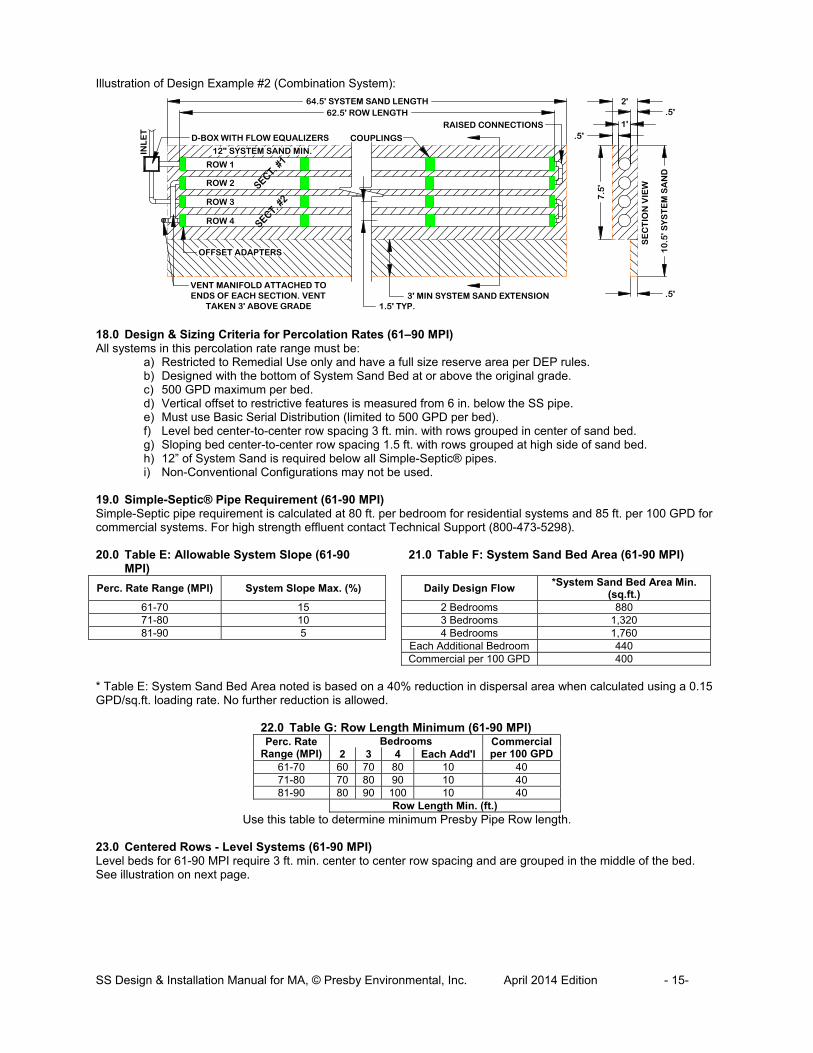
Illustration of Design Example #2 (Combination System):
18.0 Design & Sizing Criteria for Percolation Rates (61–90 MPI) All systems in this percolation rate range must be:
a) Restricted to Remedial Use only and have a full size reserve area per DEP rules. b) Designed with the bottom of System Sand Bed at or above the original grade. c) 500 GPD maximum per bed. d) Vertical offset to restrictive features is measured from 6 in. below the SS pipe. e) Must use Basic Serial Distribution (limited to 500 GPD per bed). f) Level bed center-to-center row spacing 3 ft. min. with rows grouped in center of sand bed. g) Sloping bed center-to-center row spacing 1.5 ft. with rows grouped at high side of sand bed. h) 12” of System Sand is required below all Simple-Septic® pipes. i) Non-Conventional Configurations may not be used.
19.0 Simple-Septic® Pipe Requirement (61-90 MPI) Simple-Septic pipe requirement is calculated at 80 ft. per bedroom for residential systems and 85 ft. per 100 GPD for commercial systems. For high strength effluent contact Technical Support (800-473-5298). 20.0 Table E: Allowable System Slope (61-90
MPI) 21.0 Table F: System Sand Bed Area (61-90 MPI)
Perc. Rate Range (MPI) System Slope Max. (%)
Daily Design Flow *System Sand Bed Area Min.
(sq.ft.) 61-70 15 2 Bedrooms 880 71-80 10 3 Bedrooms 1,320 81-90 5 4 Bedrooms 1,760
Each Additional Bedroom 440 Commercial per 100 GPD 400
* Table E: System Sand Bed Area noted is based on a 40% reduction in dispersal area when calculated using a 0.15 GPD/sq.ft. loading rate. No further reduction is allowed.
22.0 Table G: Row Length Minimum (61-90 MPI)Perc. Rate
Range (MPI) Bedrooms Commercial
per 100 GPD 2 3 4 Each Add'l 61-70 60 70 80 10 40 71-80 70 80 90 10 40 81-90 80 90 100 10 40
Row Length Min. (ft.) Use this table to determine minimum Presby Pipe Row length.
23.0 Centered Rows - Level Systems (61-90 MPI) Level beds for 61-90 MPI require 3 ft. min. center to center row spacing and are grouped in the middle of the bed. See illustration on next page.

SS Design & Installation Manual for MA, © Presby Environmental, Inc. April 2014 Edition - 16-
ROW 1
ROW 2
ROW 3
ROW 4
12" SYSTEM SAND MIN.
VENT ROWS GROUPED UP-SLOPESIDE OF SYSTEM SAND1.5' MIN. SPACING TYP.
SY
ST
EM
SA
ND
BE
D W
IDT
H
SYSTEM SAND EXTENSION
SE
CT
ION
VIE
W
SYSTEM SAND BED LENGTH
SL
OP
E
12"
6"
6"
VE
RT
ICA
L S
EP
AR
AT
ION
TO
R
ES
TR
ICT
IVE
FE
AT
UR
E
ROW 1
ROW 2
ROW 3
SYS. SAND EXT.
VENT
ROWS CENTERED ON SYSTEM SAND BED
SE
CT
ION
VIE
W
SYSTEM SAND BED LENGTH
12"
6" TYP.
12" ALL AROUND
SYS. SAND EXT.
3'
ROW LENGTH
6"
VE
RT
ICA
L S
EP
AR
AT
ION
TO
R
ES
TR
ICT
IVE
FE
AT
UR
E
VERTICAL SEPARATION TO RESTRICTIVE FEATURE
6"
5'OVERDIG
TYP.
TILL TO 12" DEPTH
12"
6" SYS. SAND EXT.AS REQ'D TYP.
3'TYP.
LO
W
12" MIN TYP.
SIMPLE SEPTIC® ROWS CENTERED ON SAND BED
4" TOPSOIL
FILL EXTENSION 15' FROM SAND EDGE TYP
VE
NT
CROWN
Plan View:
Section View:
24.0 Grouped Rows - Sloping Systems (61-90 MPI) Sloping beds for 61-90 MPI have1.5 ft. min. row spacing and are grouped at the high side of the bed. The inspection port is placed at the end of system sand extension. Plan View:

SS Design & Installation Manual for MA, © Presby Environmental, Inc. April 2014 Edition - 17-
12"
6" SYS. SAND EXT.
ORIGINAL GRADE
LO
WV
EN
T
TILL TO 12" DEPTH
5'OVERDIG
TYP.
15' FILL EXT. TYP.
3:1
1.5'
BREAKOUT ELEVATION
6"
VERTICAL SEPARATION TO RESTRICTIVE FEATURE
Section View:
25.0 Design Procedure (61 – 90 MPI) Task 1: Find the minimum amount of SS pipe required using the daily design flow (80 ft./bedroom). Task 2: Center-to-center row spacing is 3 ft. Task 3: Verify allowable system slope from Table E (if planning to slope bed). Task 4: Find the minimum System Sand Bed Area from Table F using the daily design flow. Task 5: Select a row length suitable for the site that meets the minimum row length requirement from Table G and then calculate the number of rows required. Task 6: Calculate the System Sand Bed Width and confirm it meets Table E requirement. Increase the system sand bed width as necessary. Row spacing may also be increased. 25.1 Design Example - Single Family Residence Design Criteria: three bedrooms (330 GPD), 80 MPI percolation rate, and construct the bed level Task 1: SS pipe required for (3) bedrooms = 3 x 80 ft./bedroom = 240 ft. min. Task 2: Center-to-center row spacing is 3 ft. Task 3: Level beds allowed for all percolation rates. Task 4: Table F requires 1,320 sq. ft. of System Sand Bed Area minimum. Task 5: The site will accommodate the 80 ft. minimum row length specified by Table G. This will result in a bed with (3) rows, which provides the minimum 240 ft. required by Task 1. Task 6: The System Sand Bed Length is the 80 ft. row length + 2 ft. = 82 ft. Now we can calculate the minimum System Sand Bed Width = 1,320 sq. ft. ÷ 82 = 16.1 ft. System Illustration:
ROW 1
ROW 2
ROW 3
SYS. SAND EXT.
VENT
ROWS CENTERED ON SYSTEM SAND BED
16
.1'
SE
CT
ION
VIE
W
82' SYSTEM SAND BED LENGTH
12"
6" TYP.
12" ALL AROUND
SYS. SAND EXT.
9'
3'
80' ROW LENGTH
INSPECTION PORT
2.5'
6"
6"
VE
RT
ICA
L S
EP
AR
AT
ION
TO
R
ES
TR
ICT
IVE
FE
AT
UR
E

SS Design & Installation Manual for MA, © Presby Environmental, Inc. April 2014 Edition - 18-
26.0 Pumped System Requirements Pumped systems supply effluent to the SS System using a pump and distribution box when site conditions do not allow for a gravity system. Dosing siphons are also an acceptable means of delivering effluent to the system. 26.1.1 Alarm Massachusetts requires alarms for all pump systems. 26.1.2 Differential Venting All pump systems and dosing siphons must use differential venting (see Differential Venting, sect. 27.2, page 18). 26.1.3 Distribution Box Manifold If a distribution box manifold is utilized, velocity reduction of the incoming effluent is necessary (see Velocity Reduction, sect. 26.1.4, page 18 and Ill. of Manifolded D-Box in sect. 5.7, page 4). 26.1.4 Velocity Reduction The rate at which effluent enters the SS must be controlled. Excessive effluent velocity can disrupt solids that settle in the pipes.
a) Effluent must never be pumped directly into SS pipe. b) A distribution box or tank must be installed between the pumping chamber and the SS pipe to reduce
effluent velocity. c) Force mains must discharge into a distribution box (or equivalent) with velocity reducer and a baffle, 90°
bend, tee or equivalent (see ill. in sect. 27.4, page 19). 26.1.5 Dose Volume
a) Pump volume per dose must be no greater than 1 gallon times the total linear feet of SS pipe. b) Pump dosing should be designed for a minimum of 6 cycles per day. c) If possible, the dosing cycle should provide at least one hour of drying time between doses.
26.1.6 Basic Serial Distribution Limit Pumped systems with Basic Serial distribution are limited to a maximum dose rate of 40 gallons per minute. The D-Box outlet does not need a flow equalizer (no effluent is being divided). Never pump directly into SS pipe. 26.1.7 Combination and Multiple-Bed Distribution Limit All SS Systems with Combination Serial distribution or Multiple Bed distribution must use flow equalizers in each distribution box outlet. Each Bed or section of Combination Serial distribution is limited to a maximum of 20 gallons per minute, due to the flow constraints of equalizers. Example: pumping to a combination system with 3 sections (using 3 d-box outlets). The maximum delivery rate is (3 x 20) = 60 GPM. Always provide a means of velocity reduction. 27.0 Venting Requirements 27.1 General Rules
a) Adequate air supply is essential to the proper functioning of the SS System. b) Venting as described below is required for all systems. c) Vent openings must be located to ensure the unobstructed flow of air through the entire SS System. d) The low vent inlet must be a minimum of 3 ft. above final grade. e) One 4 in. vent is required for every 1,000 feet of SS pipe. f) A single 6 in. vent may be installed in place of up to three 4 in. vents. g) If a vent manifold is used, it must be at least the same diameter as the vent(s). h) When venting multiple beds, it is preferred that each bed be vented separately rather than manifolding
bed vents together. i) Remote Venting (see, sect. 27.8, page 20) may be utilized to minimize the visibility of vent stacks.
27.2 Differential Venting
a) Differential venting is the use of high and low vents in a system. b) In a gravity system, the roof stack acts as the high vent. c) High and low vent openings must be separated by a minimum of 10 vertical feet. d) If possible, the high and low vents should be of the same capacity. e) Sch. 40 PVC or equivalent should be used for all vent stacks.
SS Design & Installation Manual for MA, © Presby Environmental, Inc. April 2014 Edition - 19-
VENT STACK
ROW #1
ROW #2
ROW #3 VE
NT
MA
NIF
OL
D
D-BOX
SE
CT
ION
#1
RO
WS
1 -
3S
EC
TIO
N #
2R
OW
S 4
- 6
ROW #1
ROW #2
ROW #3
ROW #4
ROW #5
ROW #6
VE
NT
MA
NIF
OL
D C
ON
NE
CT
TO
E
ND
S O
F E
AC
H S
ER
IAL
SE
CT
ION
VENT STACK
FINAL GRADE
HIG
H V
EN
TD-BOX
SU
PP
OR
T
LO
W V
EN
T
3'
10
'M
IN
TO END OF ROW
ALTERNATE LOW VENT LOCATION
LOW VENT(AIR INLET)
VENTING IS ESTABLISHED THROUGH SUCTION (CHIMNEY EFFECT) CREATED BY THE DRAW OF AIR FROM THE HIGH VENT, WHICH DRAWS AIR FROM THE LOW VENT, THROUGH THE LEACH FIELD,
THROUGH THE SEPTIC TANK, AND EXHAUSTED THROUGH THE (HIGH) ROOF VENT.
ROOF VENT (HIGH VENT,EXHAUST - CREATES SUCTION)
INLET BAFFLE WITH OPEN TOP
OUTLET BAFFLE
NOTES:1. IF AN EFFLUENT FILTER IS USED IT MUST BE PROPERLY MAINTAINED TO ENSURE ADEQUATE AIR FLOW.
2. DO NOT USE CHARCOAL FILTERS ON VENTS. THEY CAN RESTRICT AIR FLOW.
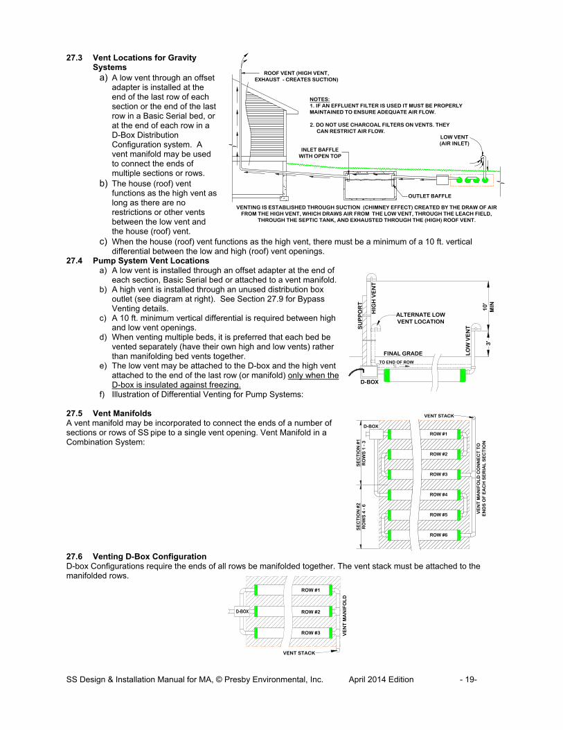
27.3 Vent Locations for Gravity Systems
a) A low vent through an offset adapter is installed at the end of the last row of each section or the end of the last row in a Basic Serial bed, or at the end of each row in a D-Box Distribution Configuration system. A vent manifold may be used to connect the ends of multiple sections or rows.
b) The house (roof) vent functions as the high vent as long as there are no restrictions or other vents between the low vent and the house (roof) vent.
c) When the house (roof) vent functions as the high vent, there must be a minimum of a 10 ft. vertical differential between the low and high (roof) vent openings.
27.4 Pump System Vent Locations a) A low vent is installed through an offset adapter at the end of
each section, Basic Serial bed or attached to a vent manifold. b) A high vent is installed through an unused distribution box
outlet (see diagram at right). See Section 27.9 for Bypass Venting details.
c) A 10 ft. minimum vertical differential is required between high and low vent openings.
d) When venting multiple beds, it is preferred that each bed be vented separately (have their own high and low vents) rather than manifolding bed vents together.
e) The low vent may be attached to the D-box and the high vent attached to the end of the last row (or manifold) only when the D-box is insulated against freezing.
f) Illustration of Differential Venting for Pump Systems: 27.5 Vent Manifolds A vent manifold may be incorporated to connect the ends of a number of sections or rows of SS pipe to a single vent opening. Vent Manifold in a Combination System: 27.6 Venting D-Box Configuration D-box Configurations require the ends of all rows be manifolded together. The vent stack must be attached to the manifolded rows.

SS Design & Installation Manual for MA, © Presby Environmental, Inc. April 2014 Edition - 20-
2" MIN. OVER SIMPLE SEPTIC PIPE
WRAP WITH GEO-TEXTILE FABRIC AND PLACE WASHED
STONE AROUND ELBOW
SCH. 40 PVC OR EQUAL RECOMMENDED FOR HIGH VENT
HIGH GROUND WATER TABLE
10
' MIN
3'
MIN
DRILL SEVERAL 1/4"Ø HOLES AT LOW POINT OF ELBOW TO DRAIN CONDENSATION.
DISGUISE VENT IN TREEDISGUISE LOW
VENT IN SHRUBS
SCREEN VENT OPENINGS
TOP OF DISTRIBUTION BOX
WRAP WITH GEO-TEXTILE FABRIC AND PLACE WASHED
STONE AROUND ELBOW
NO
T A
LL
RO
WS
AR
E S
HO
WN
SLOPE
LO
W V
EN
T
HIG
H V
EN
T
FINAL GRADE
HIGH GROUND WATER TABLE
SLOPESLOPE
SLOPE
DISTRIBUTION BOX
2" MIN OVER
SIMPLE SEPTIC PIPE
REMOTE DIFFERENTIAL VENTING(NOT TO SCALE)
SLOPE
SLOPE
BY-PASS VENT
ATTACH BY-PASS VENT TO PUMP CHAMBER OR UNUSED
OPENING IN SEPTIC TANK
WHEN USING BY-PASS VENTING THE ROOF VENT REPLACES THE "HIGH" VENT AND PUMP CHAMBER
VENT (IF REQ'D). THE OPENING OF ROOF VENT MUST BE AT LEAST 10 FT. ABOVE OPENING OF LOW VENT
D-BOX
FINISH GRADE
SEPTIC TANK WITH SANITARY TEE BAFFLES
PUMP CHAMBER
BY-PASS VENTING REPLACES BOTH THE HIGH VENT AND PUMP CHAMBER
VENT (IF REQUIRED)
EL
IMIN
AT
ED
LOW VENT IS AIR INTAKE
ENILPMUP
TO D-BOX
NO EFFLUENT FILTER
ADD PUMP CHAMBER BY-PASS VENT IF EFFLUENT FILTER IS USED ON SEPTIC TANK OUTLET BAFFLE
A
A
PUMP CHAMBER BY-PASS VENT HIGHER THAN INLET
& ABOVE TOP OF TANK
VIEW A-A(ROTATED 90°)
SEPTIC TANK
OPTIONAL CONFIGURATION(IF EFFLUENT FILTER USED)
SEPTIC TANK
PUMP BOX
10' MIN
3'
PMUPLINE
PRESBY FIELD
NOTES:
1. NOT TO BE USED WITH GRAVITY SYSTEMS.
2. INVERT OF PIPE EXITING D-BOX MUST RISE 2" MINIMUM ABOVE D-BOX.
3. USE 4" SCH. 40 PVC OR EQUAL FOR BY-PASS VENTING.
4. GLUE ALL PVC JOINTS OR EQUAL.
27.7 Vent Piping Slope Vent piping should slope downward toward the system to prevent moisture from collecting in the pipe and blocking the passage of air. 27.8 Remote Venting If site conditions do not allow the vent pipe to slope toward the system, or the owner chooses to utilize remote venting for aesthetic reasons (causing the vent pipe not to slope toward the system), the low point of the vent line must be drilled creating several ¼ in. holes to allow drainage of condensation. This procedure may only be used if the vent pipe connecting to the system has a high point that is above the highest point of all SS pipes or the D-Box., Illustration of Remote Venting:
27.9 By-Pass Venting By-Pass venting is used to eliminate the need for a High vent at the field and can also replace the need for a pump chamber vent. There must be at least 10 ft. of elevation between the roof stack and low vent openings. Illustration of By-Pass venting:

SS Design & Installation Manual for MA, © Presby Environmental, Inc. April 2014 Edition - 21-
28.0 Site Selection 28.1 Determining Site Suitability Refer to Massachusetts Rules regarding site suitability requirements. 28.2 Topography The system must be located in an area that does not concentrate water, both surface and subsurface. If allowed by state and local authorities, altering the terrain upslope of a system may alleviate this requirement if the waters are sufficiently altered to redirect flows away from the field. Avoid swales, low areas, or toe-of-slope areas that may not provide sufficient drainage away from the system. 28.3 Surface Water Diversions Surface water runoff must be diverted away from the system. Diversions must be provided up-slope of the system and designed to avoid ponding. Systems must not be located in areas where surface or groundwater flows are concentrated. 28.4 Dispersal Area Systems must be located where adjacent soils in the proposed system location and a 50 ft. perimeter are suitable for dispersing water away from the system. 28.5 Containment Systems should not be located where structures such as curbs, walls or foundations might adversely restrict the soil’s ability to transport water away from the system. 28.6 Hydraulic loading Systems should not be located where lawn irrigation, roof drains, or natural flows increase water loading to the soils around the system. 28.7 Access Systems should be located to allow access for septic tank maintenance and to at least one end of all SS rows whenever possible. Planning for future access will facilitate Rejuvenation in the unlikely event the system malfunctions. (See System Bacteria Rejuvenation and System Expansion, sect. 30.0, page 23.) 28.8 Rocky or Wooded Areas Avoid locating systems in rocky or wooded areas that require additional site work, since this may alter the soil’s ability to accept water. No trees or shrubs should be located within 10 ft. of the system to prevent root infiltration. 29.0 Installation Requirements, Component Handling and Site Preparation 29.1 Component Handling
a) Keep mud, grease, oil, etc. away from all components. b) Avoid dragging pipe through wet or muddy areas. c) Store pipe on high and dry areas to prevent surface water and soil from entering the pipes or
contaminating the fabric prior to installation. d) The outer fabric of the SS pipe is ultra-violet stabilized; however, this protection breaks down after a
period of time in direct sunlight. To prevent damage to the fabric, cover the pipe with an opaque tarp if stored outdoors.
29.2 Critical Reminder Prevent Soil Compaction It is critical to keep excavators, backhoes, and other equipment off the excavated or tilled surface of a bed. Before installing the System Sand, excavation equipment should be operated around the bed perimeter; not on the bed itself. 29.3 Site Preparation Prior to Excavation
a) Locate and stake out the System Sand bed, extension areas and soil material cover extensions on the site according to the approved plan.
b) Install sediment/erosion control barriers prior to beginning excavation to protect the system from surface water flows during construction.
c) Do not travel across or locate excavation equipment within the portion of the site receiving System Sand. d) Do not stockpile materials or equipment within the portion of the site receiving System Sand. e) It is especially important to avoid using construction equipment down slope of the system to prevent soil
compaction.

SS Design & Installation Manual for MA, © Presby Environmental, Inc. April 2014 Edition - 22-
WELDED REBARHANDLE
BERM SAND AT BASE OF PIPES TO HOLD IN PLACE
WOODEN FRAME
29.4 When to Excavate a) Where wet soils are encountered, follow the DEP requirements from 310 CMR 15.255(6) to maintain soil
integrity. b) Do not excavate the system area immediately before, during, or after precipitation.
29.5 Tree Stumps
a) Tree stumps shall be removed from the receiving area. b) Avoid soil disturbance, relocation, or compaction. c) Avoid mechanical leveling or tamping of dislodged soil. d) Fill all voids created by stump or root removal with System Sand.
29.6 Raking and Tilling Procedures All areas receiving System Sand, sand fill and fill extensions must be raked or tilled. If a backhoe/excavator is used to till the site, fit it with chisel teeth and till the site. The excavator should remain outside of the proposed System Sand area and extensions. Equipment with tires must never enter the receiving area due to likely wheel compaction of underlying soil structures.
a) For in-ground bed systems, excavate the system bed as necessary below original grade. Using an excavator or backhoe, tilt the bucket teeth perpendicular to the bed and use the teeth to rake furrows 2 in.- 6 in. deep into the bottom of the entire area receiving System Sand or sand fill (“receiving area”).
b) For elevated bed systems remove the “O” horizon (all organics) "A" topsoil (1-60 MPI only) and "E" mineral layers, then use an excavator or backhoe to rake furrows 7 in. – 8 in. deep (12 in. deep for 61-90 MPI) into the receiving area. Create a transition layer by tilling System Sand or sand fill into the receiving layer prior to bed construction.
29.7 Organic Material Removal Before tilling, remove all grass, leaves, sticks, brush and other organic matter. For 1-60 MPI systems also remove the "A" topsoil and "E" mineral layers from the excavated system site. For 61-90 MPI systems remove all organics but leave the topsoil in place. It is not necessary for the soil of the system site to be smooth when the site is prepared. 29.8 Install System Sand and/or Sand Fill Immediately After Excavation
a) To protect the tilled area (System Sand bed area and System Sand extension area) from damage by precipitation, System Sand should be installed immediately after tilling (6 in. minimum).
b) When installing the System Sand, work off either end or the uphill side of the system to avoid compacting soil (see “Critical Reminder” in sect. 29.2, page 21).
c) When installing System Sand, keep at least 6 in. of sand between the vehicle tracks and the tilled soil of the site if equipment must work on receiving soil.
d) Track construction equipment should not travel over the installed system area until at least 12 in. of cover material is placed over the SS pipes.
e) Heavy equipment with tires must never enter the receiving area due to likely wheel compaction of underlying soil structures.
29.9 Distribution Box Installation To prevent movement, be sure D-boxes are placed level on compacted soil, sand, pea gravel base, or concrete pad. 29.10 Level Row Tolerances Use a laser level or transit to install rows level. Variations beyond a total of 1 in. (±1/2" from specified elevation) may affect system performance and are not acceptable. 29.11 Row Spacers System Sand may be used to keep pipe in place while covering, but simple tools may also be constructed for this purpose. Two examples are shown to the right. One is made from rebar, the other from wood. Center-to-center row spacing noted in this manual are minimum distances. Larger row spacing is always allowed. Caution: Remove all tools used as row spacers before final covering.
SS Design & Installation Manual for MA, © Presby Environmental, Inc. April 2014 Edition - 23-
29.12 Connect Rows Using Raised Connections Raised connections consist of offset adapters, 4 in. PVC sewer and drain pipe (the Offset Adapter will accept up to 4 in. sch. 40 PVC), and 90° elbows. Use raised connections to connect the rows of the SS System (see sect. 3.4, p. 3). 29.13 Backfilling Rows
a) Spread System Sand between the rows. b) Stand between two rows of pipe and walk heel-to-toe its entire length, ensuring that System Sand fills all
void spaces beneath the SS pipe. Repeat this for all the rows. c) Finish spreading System Sand to the top of the rows and leave them exposed for inspection purposes.
29.14 Backfilling and Final Grading Spread System Sand to a minimum of 6 in. over the pipe and a minimum of 12 in. beyond the SS rows on all four sides. Spread soil material free of organics, stones over 4 in. and building debris, having a texture similar to the soil at the site, without causing compaction. Construction equipment should not travel over the installed system area until at least 12 in. of cover material is placed over the SS pipes (H-10 Loading). 18 in. of cover material over the SS System is required for H-20 loading (see sect. 5.14, page 5). 29.15 Fill Extensions Requirements All SS Systems with any portion of the System Sand bed above original grade require fill extensions on all sides beyond the outside edge of all pipes starting at the edge of the System Sand then tapering to meet existing grade at a maximum slope of 3:1. In a system sloping more than 10%, a 3 ft. System Sand extension is required on the down slope edge of the bed. See Fill Extensions and Side Slope Tapers, sect. 6.3, page 8. 29.16 System Soil Cover Material A minimum of 4 in. of suitable earth cover (topsoil or loam), with a texture similar to the soil at the site and capable of sustaining plant growth, must be placed above the installed system. Refer to Topsoil ("a.k.a" Loam), sect. 5.31, page7. 29.17 Erosion Control To prevent erosion, soil cover above the system shall be planted with native, shallow-rooted vegetation such as grass, wildflowers and certain perennials or ground covers. 30.0 System Bacteria Rejuvenation and Expansion This section covers procedures for bacteria rejuvenation and explains how to expand existing systems. Note: Presby Environmental, Inc. must be contacted for technical assistance prior to attempting rejuvenation procedures. 30.1 Why would System Bacteria Rejuvenation be Needed? Bacteria rejuvenation is the return of bacteria to an aerobic state. Flooding, improper venting, alteration or improper depth of soil material cover, use of incorrect sand, sudden use changes, introduction of chemicals or medicines, and a variety of other conditions can contribute to converting bacteria in any system from an aerobic to an anaerobic state. This conversion severely limits the bacteria’s ability to effectively treat effluent, as well as limiting liquids from passing through. A unique feature of the SS System is its ability to be rejuvenated in place. 30.2 How to Rejuvenate Bacteria System bacteria are “rejuvenated” when they return to an aerobic state. By using the following procedure, this can be accomplished in most SS Systems without costly removal and replacement. Notification of the local Health Officer may be required before attempting any rejuvenation.
1. Contact Presby Environmental before attempting Rejuvenation for technical assistance. 2. Determine the problem causing the bacteria conversion. 3. Drain the system by excavating one end of all the rows and removing the offset adapters. 4. If foreign matter has entered the system, flush the pipes. 5. Safeguard the open excavation. 6. Guarantee a passage of air through the system. 7. Allow all rows to dry for 72 hours minimum. The System Sand should return to its natural color. 8. Re-assemble the system to its original design configuration. As long as there is no physical damage to
the SS components, the original components may be reused.
30.3 System Expansion SS Systems are easily expanded by adding equal lengths of pipe to each row of the original design or by adding additional equal sections. All system expansions must comply with State and local regulations. Permits may be required prior to system expansion.

SS Design & Installation Manual for MA, © Presby Environmental, Inc. April 2014 Edition - 24-
30.4 Reusable Components SS components are not biodegradable and may be reused. In cases of improper installation it may be possible to excavate, clean, and reinstall all system components. 30.5 System Replacement If an SS System requires replacement:
a) Remove the existing components and contaminated sand. b) Replace in the same excavated location with new System Sand. c) If components are not damaged, they may be flushed and reused. d) All system replacements must comply with State and Local regulations.
31.0 Operation & Maintenance 31.1 Proper Use The SS Wastewater Treatment System requires minimal maintenance provided the system is not subjected to abuse. An awareness of proper use and routine maintenance will guarantee system longevity. We encourage all system owners and service providers to obtain and review a copy of our Owner’s Manual, available from our website www.PresbyEnvironmental.com or via mail upon request to (800) 473-5298 or [email protected]. 31.2 System Abuse Conditions The following conditions constitute system abuse:
a) Liquid in high volume (excessive number of occupants, excessive use of water in a short period of time, leaking fixtures, whirlpool tubs, hot tubs, water softening equipment or additional water discharging fixtures if not specified in system design).
b) Solids in high volume (excessive number of occupants, paper products, personal hygiene products, garbage disposals or water softening equipment if not specified in system design)
c) Antibiotic medicines in high concentrations d) Cleaning products in high concentrations e) Fertilizers or other caustic chemicals in any amount f) Petroleum products in any amount g) Latex and oil paints h) System suffocation (compacted soils, barrier materials, etc.)
Special Note: Presby Environmental, Inc., and most regulatory agencies do not recommend the use of septic system additives.
31.3 System Maintenance/Pumping of the Septic Tank
a) Inspect the septic tank at least once every two years under normal usage. b) Pump the tank when surface scum and bottom sludge occupy one-fourth or more of the liquid depth of
the tank. c) If a garbage disposal is used, the septic tank will likely require more frequent pumping. d) After pumping, inspect the septic tank for integrity to ensure that no groundwater is entering it. Also
check the integrity of the tank inlet and outlet baffles and repair if needed. e) Inspect the system to ensure that vents are in place and free of obstructions. f) Effluent filters (if used) require ongoing maintenance due to their tendency to clog and cut off oxygen to
the System. Follow filter manufacturer’s maintenance instructions and inspect filters frequently.
31.4 Site Maintenance It is important that the system site remain free of shrubs, trees, and other woody vegetation to within a minimum of 10 ft. of the system, including the entire System Sand bed area, and areas impacted by side slope tapering and perimeter drains (if used). Roots can infiltrate and cause damage or clogging of system components. If a perimeter drain is used, it is important to make sure that the outfall pipes are screened to prevent animal activity. Also check outfall pipes regularly to ensure that they are not obstructed in any way. 32.0 Glossary This Manual contains terminology which is common to the industry and terms that are unique to the Simple-Septic® Systems. While alternative definitions may exist, this section defines how these terms are used in this Manual. 32.1 Simple-Septic® (SS) Pipe A single unit comprised of corrugated plastic pipe which is surrounded by a sewn geo-textile fabric, is 10 ft. in length, with an outside diameter of 12 in. and a storage capacity of approximately 58 gallons. Each foot of Simple-Septic® provides over 15 sq.ft. of total surface area for bacterial activity. The sewn seam is always oriented up (12 o'clock position) within the bed. Pipes are joined together with couplings to form rows. Simple-Septic® is a combined wastewater treatment and dispersal system. (See definition of Row below.)

SS Design & Installation Manual for MA, © Presby Environmental, Inc. April 2014 Edition - 25-
32.2 Simple-Septic® Systems An onsite wastewater treatment and dispersal system constructed using SS pipe in a System Sand bed that receives septic tank effluent through Basic Serial distribution, Combination Serial distribution, Distribution Box (“parallel”) or Multiple Bed distribution. 32.3 Basic Serial Distribution Basic Serial distribution incorporates SS rows in serial distribution in a single bed. See Basic Serial Distribution in sect. 7.0, on page 9. 32.4 Bottom Drain A Bottom Drain is a line connected to the hole in the 6 o’clock position of a Double Offset Adapter at the end of each serial section or each row in a D-Box Distribution Configuration which drains to a sump and is utilized to lower the water level in a saturated system or to facilitate system rejuvenation. 32.5 Butterfly Configuration A variation of a standard, single bed system with the D-box located in the center, with rows oriented symmetrically on either side, and with each side or section receiving an equal volume of flow from the D-Box. See Butterfly Configuration, sect. 9.2, on page 11. 32.6 Center-to-Center Row Spacing The distance from the center of one SS row to the center of the adjacent row. 32.7 Combination Serial Distribution Incorporates two or more serial sections of SS in a single bed, with each section receiving a maximum of 500 GPD of effluent from a distribution box. See Combination Serial Distribution, sect. 9.0, on page 10. 32.8 Coupling A plastic fitting that joins two SS pipe pieces in order to form rows. See sect. 3.3, page 3. 32.9 Daily Design Flow The peak daily flow of wastewater to a system, expressed in gallons per day (GPD); systems are typically sized based on the daily design flow. Design flow calculations are set forth in the Massachusetts Rules. In general, actual daily use is expected to be one-half to two-thirds less than “daily design flow.” 32.10 Differential Venting A method of venting an SS System utilizing high and low vents (see sect. 27.2, page 18). 32.11 Distribution Box or “D-Box” A device designed to divide and distribute effluent from the septic tank equally to each of the outlet pipes that carry effluent into the SS System. D-Boxes are also used for velocity reduction, see Velocity Reduction, sect. 26.1.4, page 18. 32.12 Distribution Box (D-Box) Layout A design in which each SS row receives effluent from a distribution box outlet. Such a system is also called a “parallel system” or a “finger system.” See D-Box (Parallel) Distribution, sect. 8.0, page 9. 32.13 Distribution Box Manifold A PVC configuration which connects several distribution box outlets together in order to equalize effluent flow. Refer to drawing in sect. 5.8, on page 4. 32.14 Double Offset Adapter A double offset adapter is a plastic fitting 12 in. in diameter with two 4 in. holes designed to accept a 4 in. inlet pipe, raised connection, vent or vent manifold, and/or bottom drain, depending upon the particular requirements of the design configuration (see sect. 3.2, page 3). 32.15 End-to-End Configuration Consists of two or more beds constructed in a line (i.e., aligned along the width of the beds). See sect. 9.1, page 10. 32.16 Fill Extension Utilized in constructing Elevated (mound) Systems to blend the raised portion of the system with side slope tapering to meet existing grade (see sect. 6.3, page 8).

SS Design & Installation Manual for MA, © Presby Environmental, Inc. April 2014 Edition - 26-
32.17 Flow Equalizer An adjustable plastic insert installed in the outlet pipes of a D-Box to equalize effluent distribution to each outlet. 32.18 GPD An acronym for Gallons Per Day. 32.19 GPM An acronym for Gallons Per Minute. 32.20 High and Low Vents Pipes used in differential venting. Detailed information about venting requirements can be found in Venting Requirements, sect. 27.0, page 18. 32.21 LTAR An acronym for Long Term Acceptance Rate.
32.22 MPI An acronym for Minutes Per Inch and is the numerical value by which percolation rates (also called “perc. rates”) are expressed. 32.23 Multiple Bed Distribution Incorporates two or more beds, each bed with Basic Serial, Combination Serial, or D-Box distribution and receiving effluent from a distribution box. 32.24 Non-Conventional Configurations Have irregular shapes or row lengths shorter than 30 ft. in order to accommodate site constraints and are limited to 1-60 MPI. See Non-conventional Configurations, sect. 12.0, page 11. 32.25 Offset Adapter A plastic fitting with a 4 in. hole installed at the 12 o’clock position which allows for connections from one row to another and for installation of venting (see sect. 3.2, page 3). 32.26 Percolation Rate Also known as Perc. Rate, is a numerical indication of a soil’s hydraulic capacity, expressed in minutes per inch (MPI.) 32.27 Pressure Distribution A pressurized, small-diameter pipe system used to deliver effluent to an absorption field. Pressure Distribution is not permitted to be used with the SS System. The SS Systems are designed to promote even distribution without the need for pressure distribution. 32.28 Pump Systems Utilize a pump to gain elevation in order to deliver effluent to a distribution box. See Pump System Requirements, sect. 26.0, page 18. 32.29 Raised Connection A U-shaped, 4” diameter, PVC pipe configuration which is used to connect rows oriented in a serial configuration and to achieve the proper liquid level inside each row. See drawing in Components, sect. 3.4, page 3. 32.30 Raking and Tilling Refers to methods of preparing the native soil that will be covered with System Sand or Sand Fill, creating a transitional layer between the sand bed and the soil. See Raking and Tilling Procedures, sect. 29.6, page 22. 32.31 Row A number of SS pipe sections connected by couplings with an Offset Adapter on the inlet end and an offset Adapter or Double Offset Adaptor on the opposite end. Rows are typically between 30 ft. & 100 ft. long. 32.32 Section / Serial Section A group of interconnected rows receiving effluent from one distribution box outlet. Sections are limited to 500 GPD daily design flow maximum. 32.33 Serial Distribution Two or more SS rows connected by a raised connection. Basic Serial distribution is described in detail in sect. 7.0 on page 9, Combination Serial distribution is described in detail in sect. 9.0, on page 10.

SS Design & Installation Manual for MA, © Presby Environmental, Inc. April 2014 Edition - 27-
32.34 SHWT An acronym for Seasonal High Water Table. 32.35 Side-to-Side Configuration Consist of two or more beds arranged so that the rows are parallel to one another. 32.36 Slope (3:1) In this Manual's illustrations, slope is expressed as a ratio of run to rise. Example: A slope with a grade of (3:1) is the difference in horizontal distance of (3) ft. (run) over an elevation difference of one (1) ft. (rise). 32.37 Slope (%) Expressed as a percent, is the difference in elevation divided by the difference in horizontal distance between two points on the surface of a landform. Example: A site slope of one (1) percent is the difference in elevation of one (1) foot (rise) over a horizontal distance of one hundred (100) feet (run). 32.38 Smearing The mechanical sealing of soil air spaces along an excavated, tilled or compressed surface. This is also referred to as “compacting.” In all installations, it is critical to avoid smearing or compacting the soils under and around the field. 32.39 Surface Diversion A natural or manmade barrier that changes the course of water flow around an onsite system’s soil absorption field. 32.40 Surrounding Sand Clean sand, free of organic materials and meeting the specifications set forth in 310 CMR 15.255. Surrounding Sand is used to raise the elevation of the system to meet required separation distance or in the over dig areas. System Sand may be used for Surrounding Sand. 32.41 System Sand Bed System Sand area required/used in SS Systems. The System Sand bed extends a minimum of 6 in. below (1-60 MPI systems), 12 in. below (61-90 MPI systems), 6 in. above and 12 in. horizontally from the outside edges of the pipes in the system. System Sand must be clean, granular sand free of organic matter and must adhere to ASTM C-33 with no more than 3% passing the #200 sieve (see complete details in sect. 5.25, page 7). 32.42 System Sand Extension Area Any portion of the System Sand bed that is more than 1 ft. away from SS pipe. The System Sand extension area is a minimum of 6 in. deep. A System Sand extension area is required on the down slope side of systems sloping more than 10% and extends a minimum of 3 ft. beyond the tall portion of the down slope edge of the System Sand bed (see ill. in sect. 6.3, page 8). 32.43 Topsoil (a.k.a. Loam or Soil Cover Material) Topsoil, also known as Loam, is soil material cover capable of sustaining plant growth which forms the topmost layer of cover material above the system (see sect. 5.31, page 7).

SS Design & Installation Manual for MA, © Presby Environmental, Inc. April 2014 Edition - 28-
33.0 Massachusetts Simple-Septic® System Installation Form
Installers must complete and fax or mail a copy of this form to the local approving authority and to: Presby Environmental, Inc., 143 Airport Rd, Whitefield, NH 03598 Fax: (603) 837-9864
Installer’s Name:
Installer’s PEI Certification Number:
Company Name: Street Address: City:
State: Zip:
Installer’s Phone Number: Designer’s Name:
Company Name:
Street Address: City: State: Zip:
Phone Number: Property Owner(s): Site Street Address: City:
State: Zip:
System Information (check all that apply):
New Construction Replacement Mound In ground Gravity Pump to D-Box Serial Distribution Number of Beds: _______________ Effluent Filter Used Design Flow (bedrooms or GPD):_____________ Perc. Rate: ___________ Installation Date:
System Startup Date:
State Permit Number: Local Construction Permit Number:
Comments:
L