master assembly - freeola
TRANSCRIPT
Master Assembly
ORION W1S/T
AM 071
AM 071 (Part) 1

1 PREFACE The following extracts are taken from the Master Assembly Manual for the Orion, to cover the layout of the organ modules, testing, and cable-form wiring.
2 TABLE OF CONTENTS 1 Preface.....................................................................................................................................................................................Error! Bookmark not defined. 2 Table of Contents ....................................................................................................................................................................Error! Bookmark not defined.
2.1 FIGURES.........................................................................................................................................................................................................................................................................3 2.2 TABLES ..........................................................................................................................................................................................................................................................................3
3 Initial Operation and Adjustments ........................................................................................................................................................................................... 5 3.1 Preparations......................................................................................................................................................................................................................................................................5 3.2 Conventions and Initial Conditions..................................................................................................................................................................................................................................5 3.3 First-Time Power On .......................................................................................................................................................................................................................................................6 3.4 Testing of the L/Man Drawbars .......................................................................................................................................................................................................................................6 3.5 Testing of the U/Man Drawbars.......................................................................................................................................................................................................................................6 3.6 Testing of the Envelope Control ......................................................................................................................................................................................................................................6
3.6.1 Fixed Stop Voices of the Lower Manual .................................................................................................................................................................................................................7 3.7 Testing of the Fixed Stops of the Upper Manual .............................................................................................................................................................................................................7
3.7.1 Fixed Stop Voices of the Upper Manual ..................................................................................................................................................................................................................7 3.8 Testing of the Frequency Vibrato ....................................................................................................................................................................................................................................8
3.8.1 General Procedure in Trouble-Shooting of Switch Functions..................................................................................................................................................................................8 3.9 Testing of the Slalom Modes (Autoglide)........................................................................................................................................................................................................................9 3.10 Testing of the Selector Switches "Drawbars/Fixed Stop"..............................................................................................................................................................................................10 3.11 Testing of the Wersivoice ..............................................................................................................................................................................................................................................10 3.12 Testing of the Swell Pedal and Reverb ..........................................................................................................................................................................................................................11 3.13 Testing of the Special Effects ........................................................................................................................................................................................................................................11 3.14 Testing of the Pedals ......................................................................................................................................................................................................................................................11 3.15 Testing of the Piano, Wersidata Registration Programming and Wersimatic Rhythm/Auto Accompaniment ..............................................................................................................12
4 Final Steps .............................................................................................................................................................................................................................. 12
AM 071 (Part) 2

2.1 FIGURES Figure 1 Layout of the building blocks in the organ top..........................................................................................................................................................................................................4 Figure 2 Block diagram of the audio wiring and associated DC controls.......................................................................................................................................................................................5 Figure 3 Schematic layout of the wiring harness GO 1 ........................................................................................................................................................................................................13
2.2 TABLES Table 1 Wire List of Harness GO 1 .........................................................................................................................................................................................................................................14
AM 071 (Part) 3

Figure 1 Layout of the building blocks in the organ top
AM 071 (Part) 4

Figure 2 Block diagram of the audio wiring and associated DC controls
3 Initial Operation and
Adjustments We suppose that power supply, tone generator and electronic keyers have passed the previous tests and are in good working order (see chapter G II). We further assume that the organ is equipped with an operating power amplifier (built-in for W 1 S /external for W 1 T, connected to jack "Output" on AP 2). Only some of the connectors of the wiring harness G O 1 are to be connected at this point in time. If in doubt, verify which ones are to be plugged in by rereading chapter H IV.
3.1 Preparations Cut off a 100 cm (40") long piece of hookup wire (any color). Solder an alligator clip to one end and connect the other end to -15V of the power supply (together with the large number of blue wires). This lead will serve as test wire to activate the various analog audio switches.
3.2 Conventions and Initial Conditions A tongue tab is said to be "OFF" when it is in its upper position. A rocker tab is considered "OFF" when it is sloping down towards the rear (rear portion pushed down). A drawbar is "OFF" when it is pushed home. ( )Turn off all tongue tabs and rocker tabs.
AM 071 (Part) 5
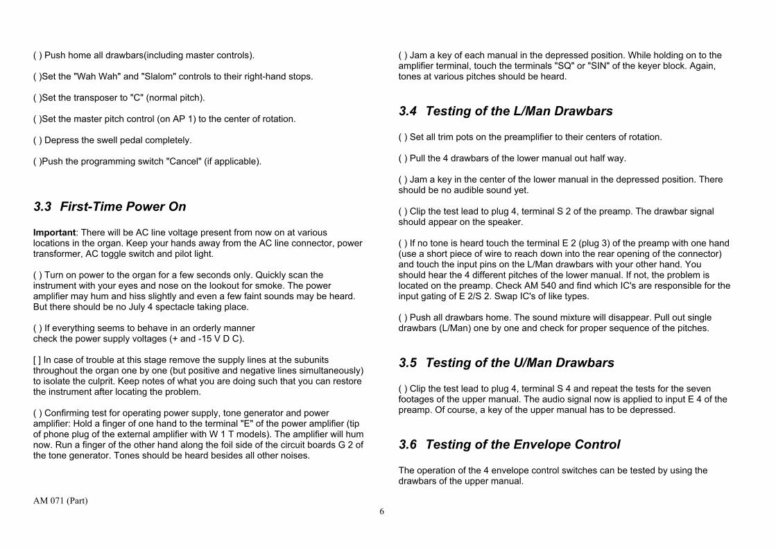
( ) Push home all drawbars(including master controls). ( )Set the "Wah Wah" and "Slalom" controls to their right-hand stops. ( )Set the transposer to "C" (normal pitch). ( )Set the master pitch control (on AP 1) to the center of rotation. ( ) Depress the swell pedal completely. ( )Push the programming switch "Cancel" (if applicable).
3.3 First-Time Power On Important: There will be AC line voltage present from now on at various locations in the organ. Keep your hands away from the AC line connector, power transformer, AC toggle switch and pilot light. ( ) Turn on power to the organ for a few seconds only. Quickly scan the instrument with your eyes and nose on the lookout for smoke. The power amplifier may hum and hiss slightly and even a few faint sounds may be heard. But there should be no July 4 spectacle taking place. ( ) If everything seems to behave in an orderly manner check the power supply voltages (+ and -15 V D C). [ ] In case of trouble at this stage remove the supply lines at the subunits throughout the organ one by one (but positive and negative lines simultaneously) to isolate the culprit. Keep notes of what you are doing such that you can restore the instrument after locating the problem. ( ) Confirming test for operating power supply, tone generator and power amplifier: Hold a finger of one hand to the terminal "E" of the power amplifier (tip of phone plug of the external amplifier with W 1 T models). The amplifier will hum now. Run a finger of the other hand along the foil side of the circuit boards G 2 of the tone generator. Tones should be heard besides all other noises.
( ) Jam a key of each manual in the depressed position. While holding on to the amplifier terminal, touch the terminals "SQ" or "SIN" of the keyer block. Again, tones at various pitches should be heard.
3.4 Testing of the L/Man Drawbars ( ) Set all trim pots on the preamplifier to their centers of rotation. ( ) Pull the 4 drawbars of the lower manual out half way. ( ) Jam a key in the center of the lower manual in the depressed position. There should be no audible sound yet. ( ) Clip the test lead to plug 4, terminal S 2 of the preamp. The drawbar signal should appear on the speaker. ( ) If no tone is heard touch the terminal E 2 (plug 3) of the preamp with one hand (use a short piece of wire to reach down into the rear opening of the connector) and touch the input pins on the L/Man drawbars with your other hand. You should hear the 4 different pitches of the lower manual. If not, the problem is located on the preamp. Check AM 540 and find which IC's are responsible for the input gating of E 2/S 2. Swap IC's of like types. ( ) Push all drawbars home. The sound mixture will disappear. Pull out single drawbars (L/Man) one by one and check for proper sequence of the pitches.
3.5 Testing of the U/Man Drawbars ( ) Clip the test lead to plug 4, terminal S 4 and repeat the tests for the seven footages of the upper manual. The audio signal now is applied to input E 4 of the preamp. Of course, a key of the upper manual has to be depressed.
3.6 Testing of the Envelope Control The operation of the 4 envelope control switches can be tested by using the drawbars of the upper manual.
AM 071 (Part) 6

( ) Clip the test lead to terminal S 4 of the preamp. This activates the drawbars of the upper manual. ( ) Turn on the switch "Soft Attack" (upper left cheek block). When depressing a key on the upper manual the tone buildup should be slower than before. ( ) Turn on the switches "Short Sustain"; "Medium Sustain" and "Long Sustain" successively. The tone decay after the release of a key should become progressively longer. ( ) Should any of these functions not operate properly fasten a second test lead to -1 5V of the power supply and clip it directly to the pins "Att. soft's "Sustain short", "Sust. medium" or "Sust. tong" on H K 13 of the upper manual. If the envelope modes now are working okay the problem will be found in the wiring (see wire list). If not the trouble is located on the envelope control boards H K 13 or H K 12 of the upper manual (though they were tested previously). Testing of the Fixed Stops of the Lower Manual ( ) Jam a key of the lower manual in the depressed position. ( ) Turn on a few fixed stops of the lower manual. ( ) Pull the volume control "L/Man " out mid-way. ( ) Push the connector from the harness G O 1 onto the pins of "Plug 2 " (GP 1 of lower manual). ( ) Clip the test lead to pin S 1 of the preamp. The selected fixed stops will now be audible. ( ) Check the presence of all fixed stops and compare the sound character with the list below: 3.6.1 Fixed Stop Voices of the Lower Manual 1. Viola 8': Bright, rich in harmonics. 2. Principal 8': Broader spectrum than Viola 8; but still rich in harmonics.
3. Horn 8': "Hollow" sound. 4. Violin 4': Same as Viola 8' but pitched one octave higher. 5. Principal 4': Broader spectrum than Violin 4; but still rich in harmonics. 6. Nasat 2-2/3': Sounds one fifth higher than the 4' stops (G appears on a c- key). This is a fill-in voice (not a solo stop) and sounds softer than the other 4'stops. 7. Principal 2': Same as Principal 4' but pitched one octave higher. 8. Salicional 2': Louder than the Principal 2'andsomewhatpiercing.
3.7 Testing of the Fixed Stops of the Upper Manual ( ) Jam a key of the upper manual in the depressed position. ( ) Turn on a few fixed stops of the upper manual. ( ) Pull the volume control "U/Man" out mid-way. ( )Push the connector from the harness G O 1 onto the pins of "Plug 2 " (GP 1 of upper manual). ( ) Clip the test lead to pin S 3 of the preamp. The selected fixed stops will now be audible. ( ) Check the presence of all fixed stops and compare the sound character with the list below 3.7.1 Fixed Stop Voices of the Upper Manual 1. Cello 16': Rich full sound with plenty of harmonics. 2. Horn 16': Hollow sound. 3.Trom bone 16': Powerful and broad sound, becoming "buzzy" at the lowest octave.
AM 071 (Part) 7

4.Saxophone16': Rich in harmonics, becoming increasingly "hollow" towards the bass end of the manual. 5. Flute 8': Round tone, few harmonics. 6. Viola 8': Bright sound, rich in harmonics. 7. Clarinet 8': Typical woodwind tone. 8. Oboe 8': Thin woodwind, brighter than clarinet 8'. 9. Trumpet 8': Loud and bright brassy tone. 10. Flute 4': Same as Flute 8; but sounds higher by an octave. 11. Violin 4': Same as Viola 8; but an octave higher, almost no fundamental tone. 12. Nasat 2-2/3': Sounds one fifth higher than the 4'stops(G appears on ac-key). Subdued voice as fill-in. 13. Piccolo 2': Powerful and bright (repeats at the highest C). 14. Flute 1': Thin add-on voice (repeats starting at the C of the 4th octave). 1 5. Mixture III: Bright harmonic complement to full-bodied voices.
3.8 Testing of the Frequency Vibrato The fixed stop voices of the upper manual can be used to test the various modes of the frequency vibrato. We suppose that the tone generator was tuned after its assembly. ( ) Push the connector from the harness G O 1 onto the pins of circuit board U S 2 " Reverb/Vibrato, etc "
( ) Verify that the pitch of the entire organ varies by an exact octave when the "Slalom" control is moved from stop to stop. Remark: If you installed a "Slalom" control which is different from the one you tested the tone generator with the generator will have to be retuned due to the resistance tolerance of different controls. Standard pitch (higher pitch) should exist with the "Slalom" control at its right-hand stop. ( ) Turn on (depress) the push button switch "Delayed Vibrato": ( ) Depress one or more keys in the upper manual. After a short delay a weak vibrato should appear. The delay is initiated every time a key is depressed after a pause in playing. The delay time can be adjusted by means of trimpot P 3 on the tone generator board G 1. Our recommendation: center of rotation. ( ) Release the button "Delayed Vibrato" and depress "Contin. Vibrato": The vibrato exists immediately when a key is depressed. ( ) In addition, depress the button "Vibrato II". The intensity (or depth) of the vibrato increases. ( ) Depress the button "Vibrato III" additionally. This causes the heaviest vibrato. By the way, the two vibrato intensity buttons ll and Ill are effective only in conjunction with a depressed "Delayed Vibrato" or "Contin. Vibrato": ( ) Depress yet the button "Slow Vibrato". The previously fast vibrato should slow down about 40%. 3.8.1 General Procedure in Trouble-Shooting of Switch
Functions All modes of operation of the various building blocks throughout the organ which are controlled by a mechanical switch are activated as follows: The switch sends a negative (-15 V D C) control voltage to the corresponding location. Since it is irrelevant from where the control voltage originates we can also activate a particular function with the help of our test wire. Example: Suppose that the function "Slow Vibrato" does not work while all other vibrato modes are operating properly. First, we trace the control voltage.
AM 071 (Part) 8

We find that the switch "Slow Vibrato" is shown in Fig. 46. The control wire is No. 7 3. The wire list states that the other end of wire No. 73 is connected to the tone generator G 1, plug A, pin 3. Using our test lead (extended with a piece of bare wire) we touch this pin on the generator. There are two possible results, namely:
a) The vibrato does not slow down, b) The vibrato slows down.
In case a) the problem is located on the tone generator board (though it was tested; did you miss that test?). In case b) we conclude that the control voltage does not arrive at the tone generator. Where did it get lost? In the harness? That is easy to verify by touching the pin 8 of the switchbank (other end of wire No. 73). If the vibrato does not slowdown we have to assume that the wire you see emerging from pin 8 is not the one arriving at pin A 3 on the generator. More likely, the vibrato will slow down, giving rise to two new questions:
a) Is the switch "Slow Vibrato" defective? b) Is the control voltage for the entire switch bank missing?
Question b) can be brushed aside immediately since the other switches of the same group do control their functions. The last locations of the trouble are, therefore, the switch itself, the foil pattern o n the board US 2, or the diode in series with the switch. Clip the positive test lead of your voltmeter (15 V DC or greater) to ground and test the following points in the indicated sequence: 1) Switchbank pin 1 (master control voltage for entire switch bank). 2) One of the two pins at the rear of the switch (no voltage = defective switch). 3) Pin 8 of the connector (no voltage = defective diode, wrong polarity of diode or interrupted foil pattern). Also refer to Fig. 26 for layout.
It took us quite a few words to describe this procedure. We hope that you understand the fundamental idea behind all trouble-shooting.
a) Identify the function that is not working. b) Locate the "sender" of the control signal (usually a switch). c) Trace the signal, using the wiring list, hookup drawings and foil pattern
reproductions of this and/or other manuals. d) Trace the path backwards by means of the test wire or follow it forwards
by using a voltmeter. Important: Keep your inner cool and -if somebody else is watching - maintain an air of "situation under complete control".
3.9 Testing of the Slalom Modes (Autoglide) ( ) Release all push buttons of the group " Reverb/ Vibrato /Slalom': Set the "Slalom " slide control to its right-hand stop. Set the transposer to "C" (normal pitch). ( ) Depress a key on the upper manual and simultaneously depress the button "Autoglide" The pitch should shift downwards by an exact octave every-time the key is depressed anew. Prerequisites: properly tuned generator and correctly positioned transposer (the knob may be at "C" but what about the switch proper?). ( ) Depress, in addition, the switch "Autoglide U p / Down". The pitch shift will be upwards now. ( ) Increase the "travel speed- of the octave glide by pulling out the slide control "Autoglide Speed". ( ) The "travel distance" can be limited to less than an octave b y moving the "Slalom" control away from its right-hand stop. This varies the high end of the pitch glide only. ( ) The transposer also changes the upper limit. Set the transposer to any other position than "C" and test the autoglide. It will move between the low "C" and the tone determined by the transposer. The slide control "Slalom" is disabled when the transposer is not at the C-position.
AM 071 (Part) 9

( ) Turn the master pitch control (underside of organ top) from stop to stop. The overall pitch of the organ should vary by about plus and minus a halftone. ( ) Activate the right-hand foot switch en the swell pedal (W 1 T only: Postpone this test until the swell pedal is connected). The pitch should drop rapidly by about a half-tone and return slowly to normal. Premature release of the "Hawaii" switch causes the pitch to return more rapidly. If you have the impression that the pitch stays slightly "flat" while the footswitch remains deflected you have a good ear (the pitch is off by about one twentieth of a half-tone). We no longer require the test lead. Remove it from the power supply.
3.10 Testing of the Selector Switches "Drawbars/Fixed Stop"
( ) Push the connector from the harness G O 1 onto the pins of "Plug 1 " of circuit board G P 1 L/Man (voicing board of lower manual). ( ) Turn on a few fixed stops in the lower manual. ( ) Pull a few drawbars of the lower manual. ( ) Push the connector for plug 4 on the preamplifier onto the pins. ( ) Set the volume control "L/Man" about mid-way. ( ) Hold a chord on the lower manual and alternate the positions of the tongue tab "Drawbars/ Fixed Stops" of the lower manual. You should hear the drawbar sound with the switch in the "up" position and the fixed stops in the "down" position. ( )Turn on all fixed stops of the lower manual. Pull out all drawbars of the lower manual. ( ) Hold down a key or chord on the lower manual. Alternate between drawbars and fixed stops and balance the volume of the fixed stops with the one from the drawbars by means of trim pot P 1 on GP 1 (L/Man).
( ) Repeat the entire procedure from the beginning of this paragraph Xl for the upper manual.
3.11 Testing of the Wersivoice ( ) Push the 3 connectors from the harness G O 1 onto the pins on the Wersivoice circuit board WV 7. ( ) Turn off any vibrato on the push buttons" Reverb/ Vibrato, etc". ( ) Select some bright fixed stops in both manuals and pull the drawbars for a matching bright sound. ( ) The switches " Drawbars to Wersivoice" and "Fixed Stops to Wersivoice" (in both manuals), when pushed down, assign the respective sounds to the Wersivoice (The switch " Drawbars/Fixed Stops" pre-selects the tone sources). The Wersivoice imposes a rather complex vibrato on the sound such that it seems to emerge from rotating speakers or baffles. The Wersivoice switches on the lower left cheek block are "off": In that case the vibrato (Whirl) is at its normal intensity and at the fast speed. ( ) Set the trimpot P 1 (Output) on the Wersivoice circuit board WV 7 to the center of rotation. ( )Find the position on P 2 (Input) on WV 7 where distortion occurs either using all drawbars or many fixed stops. Then, back off the volume until the distortion disappears. ( ) Now adjust P 1 (Output) such that the volume is the same in both positions of the switch "Draw-bars to Wersivoice" (using drawbars of the upper manual). ( ) Hold a full chord, using drawbars in the upper manual. Turn on the rocker switch "Fast/Chorale": The vibrato should be slow now (chorale speed). ( ) Turn the switch "Fast/ Chorale" off again. The vibrato speed should increase slowly until it reaches the fast (normal) speed. The Wersivoice simulates the inertial speed-up of mechanical rotators.
AM 071 (Part) 10
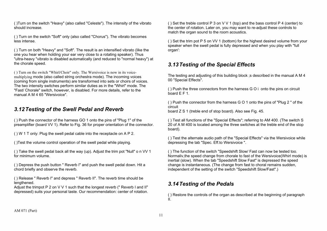
( )Turn on the switch "Heavy" (also called "Celeste"). The intensity of the vibrato should increase. ( ) Turn on the switch "Soft" only (also called "Chorus"). The vibrato becomes less intense. ( ) Turn on both "Heavy" and "Soft". The result is an intensified vibrato (like the one you hear when holding your ear very close to a rotating speaker). Thus "ultra-heavy "vibrato is disabled automatically (and reduced to "normal heavy") at the chorale speed. ( ) Turn on the switch "Whirl/Choir" only. The Wersivoice is now in its voice-multiplying mode (also called string orchestra mode). The incoming voices (coming from single instruments) are transformed into sets or choirs of voices. The two intensity switches perform similar duties as in the "Whirl" mode. The "Fast/ Chorale" switch, however, is disabled. For more details, refer to the manual A M 4 65 "Wersivoice".
3.12 Testing of the Swell Pedal and Reverb ( ) Push the connector of the harness GO 1 onto the pins of "Plug 1" of the preamplifier (board VV 1). Refer to Fig. 36 for proper orientation of the connector. ( ) W 1 T only: Plug the swell pedal cable into the receptacle on A P 2. ( )Test the volume control operation of the swell pedal while playing. ( ) Take the swell pedal back all the way (up). Adjust the trim pot "Null" o n VV 1 for minimum volume. ( ) Depress the push button " Reverb I" and push the swell pedal down. Hit a chord briefly and observe the reverb. ( ) Release " Reverb I" and depress " Reverb II". The reverb time should be lengthened. Adjust the trimpot P 2 on V V 1 such that the longest reverb (" Reverb I and II" depressed) suits your personal taste. Our recommendation: center of rotation.
( ) Set the treble control P 3 on V V 1 (top) and the bass control P 4 (center) to the center of rotation. Later on, you may want to re-adjust these controls to match the organ sound to the room acoustics. ( ) Set the trim pot P 5 on VV 1 (bottom) for the highest desired volume from your speaker when the swell pedal is fully depressed and when you play with "full organ':
3.13 Testing of the Special Effects The testing and adjusting of this building block ;s described in the manual A M 4 00 "Special Effects". ( ) Push the three connectors from the harness G O i onto the pins on circuit board E F 1. ( ) Push the connector from the harness G O 1 onto the pins of "Plug 2 " of the circuit board Z S 1 (treble end of stop board). Also see Fig. 45. ( ) Test all functions of the "Special Effects"; referring to AM 400. (The switch S 20 of A M 400 is located among the three switches at the treble end of the stop board). ( ) Test the alternate audio path of the "Special Effects" via the Wersivoice while depressing the tab "Spec. Eff.to Wersivoice ". ( ) The function of the switch "Speedshift Slow/ Fast can now be tested too. Normaliv,the speed change from chorale to fast of the Wersivoice(Whirl mode) is inertial (slow). When the tab "Speedshift Slow Fast" is depressed the speed change is instantaneous. (The change from fast to choral remains sudden, independent of the setting of the switch "Speedshift Slow/Fast".)
3.14 Testing of the Pedals ( ) Restore the controls of the organ as described at the beginning of paragraph II.
AM 071 (Part) 11

( ) Push all connectors onto the pedal electronics board P E 13. ( ) Pull the volume control "Bass guitar" (gray drawbar)abouthalf-way. ( ) Play the pedals, note for note. Adjust the percussive pluck of the bass guitar to suit your taste (trimpot P 1 on PE 13). Our recommendation: approx. 3/4 clockwise. ( ) Push the control "Bass Guitar" home and pull out the volume control "Fixed Stops". Sequentially turn on the rocker tabs "Trumpet"; "Tuba" and "Stringbass" and play the pedals. These voices have their own pre-set attack and sustain (very short). ( ) In addition to "Stringbass" turn on the tongue tab "Pedals to Wersivoice " (treble end of the stop board). Set the Wersivoice to its "Choir" mode for a very interesting pedal voice. ( ) Push all pedal controls home and turn off all pedal rocker and tongue switches. Pull the drawbars " 16"'and " 8"'singly and in combination while playing the pedals. These voices should be round and mellow. There should be a short sustain. ( ) Lengthen the sustain of the dra wbar voices by turning on the rocker tab "Long Sustain".
3.15 Testing of the Piano, Wersidata Registration Programming and Wersimatic Rhythm/Auto Accompaniment
These building blocks are to be installed, wired and tested according to their respective assembly manuals.
4 Final Steps When you reach this chapter you have completed a considerable amount of work. We congratulate you for this achievement.
But, please, tome your haste and spend some time for the final cleanup. Inspect the instrument for loose particles and tools. Use a vacuum cleaner to suck up the remaining debris. (Some small strands of wire have a tendency to lodge somewhere between terminals and components where they can cause the famous "demonstration effect" during your inaugural concert.) Fasten the swell pedal cover (W 1 S) and close up the rear panel(s). We wish you many years of enjoyment with your ORION. Since you built this instrument yourself you are thoroughly familiar with its musical capabilities. Maybe you want to start your playing experiments with duplicating some of the sounds Klaus Wunderlich displays live on his L P "Wersitime 2 ". While his registration information on the liner notes pertain to the model W 2 S, the principles hold true for the ORION models too. An electronic orchestra of the versatility of the O RION will likely lead to new discoveries in the areas of sound effects and playing tricks among the many users. We would appreciate knowing about such innovative ideas and will publish them in our newsletter for the benefit of all other musicians.
AM 071 (Part) 12

Figure 3 Schematic layout of the wiring harness GO 1
AM 071 (Part) 13

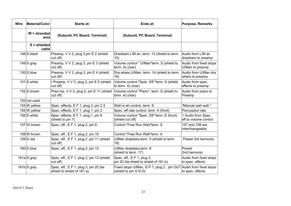
The wiring list on the following pages contains the wire numbers, colors and types of wires used in the harness GO 1. Beginning and end of each wire are also identified as to subunit name and terminal designation as far as the wiring of the organ is concerned, we do not make use of this list. It is provided as an aid in trouble-shooting and for future reference.
Table 1 Wire List of Harness GO 1
Wire Material/Color Starts at: Ends at: Purpose, Remarks
W = stranded wire (Subunit, PC Board, Terminal) (Subunit, PC Board, Terminal)
S = shielded cable
1 W blue Power supply, PS 1, -15V Tone generator, G 1, plug A, pin 8 Neg. supply voltage 2 W blue Power supply, PS 1, -15V Piano, PI 1, plug 3, pin -15V Neg. supply voltage 3 W blue Power supply, PS 1, -15V Keyers, V 1, term. -15 Neg. supply voltage 4 W blue Power supply, PS 1, -15V Wersivoice, WV 7, pin 18 (-15) Neg. supply voltage 5 W blue Power supply, PS 1, -15V Pedal electronics, P E 13, plug 7, pin -15 Neg. supply voltage 6 W blue Power supply, PS 1, -15V Preamp, VV 2, plug 5, pin - 15 Neg. supply voltage 7 W blue Power supply,PS 1, -15V Bus bar L/Man Keying voltage for
envelope control 8 W blue Power supply, PS 1, -15V Program switches, S P 1, point -15 9 W blue Power supply, PS 1, -15V Wah wah control, term. A
10 W blue Power supply, PS 1, -15V Piano, PI 13, point " Neg. supply voltage 11a W blue Power supply, PS 1, -15V Bus bar U/Man Keying voltage for
envelope control 11b W blue Bus bar U /Man Envelope control, H K 13, U /Man, term. -1
5 Neg. supply voltage
12 W blue Power supply, PS 1, -15V A P 1, master pitch control, term. A (start) Neg. supply voltage 13 W blue Power supply, PS 1, -15V Programming, P R 1, plug 2, pin 17 Neg. supply voltage 14 W blue Power supply, PS 1, -15V Spec. effects rate control, term. S (wiper) Neg. supply voltage
15a W blue Power supply, PS 1, -1 5V Spec. effects, E F 1, plug 1, pin 3 N eg. supply voltage 15b W blue Spec. effects, E F 1, plug 1, pin 3 Spec. effects, E F 1, plug 3, pin 24 Neg. supply voltage
AM 071 (Part) 14

Wire Material/Color Starts at: Ends at: Purpose, Remarks
W = stranded wire (Subunit, PC Board, Terminal) (Subunit, PC Board, Terminal)
S = shielded cable
16 W blue Power supply, PS 1, -15V Fixed stops U/M an, G P 1, plug 2, pin -15 Neg. supply voltage 17 W blue Power supply, PS 1, -15V Fixed stops L/Man, G P 1, plug 2, pin - 15 Neg. supply voltage 18 not used 19 not used 20 not used 21 W red Power suppIy,PS 1,+15V Tone generator, G 1, plug A, pin 4 Pos.supply voltage 22 W red Power supply, P S 1, +15V Piano, PI 1, plug 3, pin +15 Pos. supply voltage 23 W red Power suppIy,PS1,+15V Keyers,Vl,term.+15 Pos.supplyvoltage24 W red Power supply, PS 1, +15V Wersivoice, WV 7, pin 11 (+15) Pos.supply voltage 25 W red Power supply, PS 1, +15V Pedal electronics, P E 13, plug 7, pin +15 Pos. su p ply voltage 26 W red Power supply, PS 1, +1 5V Preamp, VV 2, plug 5, pin + 15 Pos.supply voltage
27a W red Power supply, PS 1, +1 5V Piano, PI 13, term. "+" Pos. supply voltage 27b W red Piano, Pll3,term."+" Piano, Pl12,2nd octave, term. "+" Pos.supplyvoltage 27c W red Piano, PI 12, 2nd octave, term. "+ " Piano, PI 12, 3rd octave, term. "+" Pos.supply voltage 27d W red Piano, PI 12, 3rd octave, term. "+ " Piano, PI 12, 4th octave, term. "+" Pos.supply voltage
28 W red Power supply, PS 1,+15V Spec. effects, E F 1, plug 3, pin 19 (+15V) Pos.supply voltage 29 W red Power supply, PS 1, +15V Fixed stops, U/Man, G P 1, plug 2, pin +15 Pos.supply voltage
30 W red Power suppIy,PS 1,+15V Fixed stops, L/M an, G P 1, plug 2, pin +15 Pos.supply voltage
31 not used 32 not used 33 not used 34 not used 35 not used
AM 071 (Part) 15

Wire Material/Color Starts at: Ends at: Purpose, Remarks
W = stranded wire (Subunit, PC Board, Terminal) (Subunit, PC Board, Terminal)
S = shielded cable
36 W green Programming, P R 1, plug 2, pin 15 Envelope switches, U/Man, US 1, "Soft Attack", term.P M
"Programmed Minus" (PM) for U/Man envelope
37 W green Programming, P R 1, plug 2, pin 14 Switches "Wersivoice" and "Pedals"; S 1 PM for control switches "Wersivoice/Pedals"
38 not used 39a W green Programming, P R 1, plug 2, pin 13 Push button switches " Reverb, etc.", U S
2, plug 1, pin 1 PM for switches " Reverb/Vibrato"
39b W green Switches " Reverb,etc.'; US 2, pin PM Push button switches "Piano"; U S 2, plug 1, pin 1
P M for switches "Piano"
40 W green Programming, P R 1, plug 2, pin 12 Spec. effects, E F 1, plug 3, pin 22 IPM) PM for spec. effects 41 W green Programming, P R 1, plug 2, pin 12 Fixed stops, U/M an, G P 1, plug 2, pin PM PM for fixed stops U/
M an 42 W green Programming, P R 1, plug 2, pin 11 Fixed stops, L/M an, G P 1, plug 2, pin P M P M for fixed stops
L/M an 43 W green Programming, P R 1, plug 2, pin 11 Tab switches "S peedshift,etc."; Z S 1, pin
P M PM for additional Wersivoice controls
44 not used 45 not used 46 W black Power suppIy,PS 1, G N D Tone generator, G 1, plug B, pin 8 Ground 47 W black Power supply, PS 1, G N D Piano, PI 1, plug 3, pin GND Ground 48 W black Power suppIy,PS1,G N D Keyers,V 1, term. GN D Ground 49 W black Power supply, PS 1, G N D Wersivoice, WV 7, pin 9 (G N D) Ground 50 W black Power supply, PS 1, G N D Pedal electronics, P E 13, plug 7, pin GND Ground 51 W black Power supply, PS 1, G N D Preamps, V V 2, plug 5, pin G Ground 52 W black Power suppIy,PS 1,G N D Key contacts, L/Man,H K 13,term.G N D Ground 53 W black Power supply, PS 1, G N D Program switches, SP 1, term. G N D Ground
AM 071 (Part) 16

Wire Material/Color Starts at: Ends at: Purpose, Remarks
W = stranded wire (Subunit, PC Board, Terminal) (Subunit, PC Board, Terminal)
S = shielded cable
54 W black Power suppIy,PS 1,G N D Wah wah control, term.E Ground 55 W black Power suppIy,PS 1, G N D Transposer,TP, point "M" Ground 56 W black Power suppIy,PS1,G N D Slalom control, term.A Ground 57 W black Power suppIy,PS 1,G N D Piano, P113,term.G N D Ground 58 W black Power suppIy,PS 1,G N D Envelope control, U/Man,H K 13,term.G N
D Ground
59 W black Power supply, PS 1, G N D AP 1, master pitch control, term. E Ground 60 W black Power supply, PS 1, G N D Programming, P R 1, plug 2, pin 20 Ground
61a W black Power suppIy,PS 1, G N D C-bar of shelf (solder lug) Ground 61b W black C-bar of shelf (solder lug) Stop board (solder lug) Ground
62 W black Power supply, PS 1, G N D Ground plane of master control see Fig. 52 63 W black Power suppIy,PS 1,G N D Drawbars U/Man + L/Man (solder lug) Ground 64 W black Power supply, PS 1, G N D Drawbars (Perc.) (solder lug) Ground 65 W black Power supply, PS 1, G N D Spec. effects, E F 1, plug 3, pin 21 Ground 66 W black Power supply, PS 1, G N D Fixed stops, U/M an, G P 1, plug 2, pin G N
D Ground
67 W black Power supply, PS 1, G N D Fixed stops, L/M an, G P 1, plug 2, pin G N D
Ground
68 W black Power supply, PS 1, G N D Pream ps, V V 1, plug 1, pin G Ground 69 not used 70 not used 71 W yellow Switches " R everb '; V S 2, plug 1, pin 6 Tone generator, G 1, plug A, pin 7 Delayed vibrato
72 W brown Switches " Reverb '; V S 2, plug 1, pin 7 Tone generator, G 1, plug A, pin 6 Continuous vibrato
73 W pink Switches " Reverb '; VS 2, plug 1, pin 8 Tone generator, G 1, plug A, pin 3 Slow vibrato 74 W white Switches " Reverb '; VS 2, plug 1, pin 9 Tone generator, G 1, plug A, pin 2 Vibrato II
AM 071 (Part) 17

Wire Material/Color Starts at: Ends at: Purpose, Remarks
W = stranded wire (Subunit, PC Board, Terminal) (Subunit, PC Board, Terminal)
S = shielded cable
75 L gray Switches " Reverb '; V S 2, plug 1, pin 10
Tone generator, G 1, plug A, pin 1 Vibrato III
76 L red/blue Switches " Reverb '; VS 2, plug 1, pin 11 Tone generator, G 1, plug B, pin 2 utoglide on
77a L wh/yel Slalom control, term. S Tone generator, G 1, plug B, pin 3 Autoglide spread 77b L wh/yel Switches " Reverb ...'; V S 2, plug 1, pin
12 Autoglide speed control, term. S Autoglide up/down j
78 L gn/blk Tone generator, G 1, plug B, pin 4 Solder lug strip (W 1 S) AP 2,connector"Swellpedal';term.6(W 1T)
Foot switch for Hawaii effect
79 W wh/brn Tone generator, G 1, plug B, pin 6 A P 1, master pitch control, term. S (center)
80 W yel/blk Tone generator, G 1, plug B, pin 7 Transpose r, TP, point B 7 81 W wh/blk Transposer, TP, point S --Slalo m control, term. S 82 L wh/blue Tone generator, G 1, plug B, pin 1 A utoglide speed control, term. A (front)
83a L yel/blue Tone generator, G 1, plug A, pin 5 Piano, PI 1,plug 1, pin Trig. "Key down" for generator
83b L y el/blue Piano, PI 1, plug 1, pin Trig. Spec. effects, E F 1, plug 1, pin 1 "Key down" for piano 83c L yel/blue Spec. effects, plug 1, pin 1 Envelope control, U/Man, H K 13, term.
Pere. "Key down" for special effects
84 S blue Piano, PI 1, plug 1, pin 2 (shield to pin G N D)
Piano, PI 13, term. OUT (shield cut off)
85 S white Piano, PI 1, plug 1, pin 3 (shield to pin G N D)
Piano, PI 12, 2nd oct.,term. OUT (shield cut off)
86 S red Piano, PI 1, plug 1, pin 4 (shield to pin G N D)
Piano, PI 12, 3rd oct.,term. OUT (shield cut off)
87 S gray Piano, PI 1, plug 1, pin 5 (shield to pin G N D)
Piano, PI 12, 4th oct.,term. OUT (shield cut off)
88 W yellow Piano, PI 1, plug 1, pin SPEED Tremolo speed control, term. S
AM 071 (Part) 18

Wire Material/Color Starts at: Ends at: Purpose, Remarks
W = stranded wire (Subunit, PC Board, Terminal) (Subunit, PC Board, Terminal)
S = shielded cable
89 W yellow Piano, PI 1, plug 1, pin SPEED Tremolo speed control, term. A 88 and 89 are interchangeable
90 W brown Piano, PI 1, plug 2, pin Ki. Switches "Piano"; U S 2, plug 1, pin 9 Control for Kinura 91 W red/blue Piano, PI 1, plug 2, pin Hs. Switches " Piano'; U S 2, plug 1, pin 12 Control for
Harpsichord 92 W pink Piano, PI 1, plug 2, pin Ho. Switches "Piano"; U S 2, plug 1, pin 11 Control for Honky-
Tonk 93 W white Piano, PI 1, plug 2, pin Ce. Switches "Piano"; U S 2, plug 1, pin 8 Control for Celeste 94 W gray Piano, PI 1, plug 2, pin Pi. Switches "Piano"; US 2, plug 1, pin 10 Control for Piano 95 W yel/red Piano, PI 1, plug 2, pin Ba. Switches "Piano"; U S 2, plug 1, pin 7 Control for Banjo 96 W grn/brn Piano, PI 1, plug 2, pin B. Piano, PI 13, term. B 97 W wh/yel Piano, PI 1, plug 2, pin Ec. Switches "Piano"; U S 2, plug 1, pin 2 Control for Echo 98 W wh/brn Piano, PI 1, plug 2, pin Tr. Switches "Piano", U S 2, plug 1, pin 3 Control for Tremolo 99 W wh/blk Piano, PI 1, plug 2, pin S/L Switches "Piano"; U S 2, plug 1, pin 6 Control for Sustain
100 W wh/red Piano, PI 1, plug 2, pin A Piano, PI 13, term. A 101 W grn/red Piano, PI 1, plug 2, pin Pe. Solder lug strip (W 1 S) AP 2, connector
"Swell pedal"; pin 5 (W 1 T) Foot switch for piano sustain
102 S brown Piano, PI 1, plug 3, pin OUT (shield to pin G N D)
Volume control "Piano", term. E (front) Audio output of piano
103 W yellow Wersivoice,V11V 7, pin 12 Switches, S 1,term. 7 Wersivoice "Heavy" 104 W brown Wersivoice, WV 7, pin 13 Switches, S 1,term. 8 Wersivoice "Soft" 105 W pink Wersivoice, WV 7, pin 14 Switches, S 1,term. 5 Wersivoice "Chorale/F
ast" 106 W white Wersivoice, WV 7, pin 15 Switches, S 1,term. 6 Wersivoice
"Whirl/Choir" 107 W gray Wersivoice, WV 7, pin 16 Tab switch "Speedshift"; ZS 1, plug 1, pin 3
AM 071 (Part) 19

Wire Material/Color Starts at: Ends at: Purpose, Remarks
W = stranded wire (Subunit, PC Board, Terminal) (Subunit, PC Board, Terminal)
S = shielded cable
108 W red/blue Wersivoice, WV 7, pin 1c Fixed stops L/Man, G P 1, plug 1, pin FR-WV
"Fixed Stops to Wersivoice"
109 W yel/red Wersivoice, WV 7, pin 2c Fixed stops L/Man, G P 1, plug 1, pin SIN-WV
"Drawbarsto Wersivoice"
110 W wh/yel Wersivoice, WV 7, pin 3c Fixed stops U/Man, G P 1, plug 1, pin FR-WV
"Fixed Stops to Wersivoice"
111 W wh/brn Wersivoice, WV 7, pin 4c Fixed stops U/Man, G P 1, plug 1, pin SIN-WV
" Drawbarsto Wersivoice"
112 W wh/red Wersivoice, WV 7, pin 5c Tab switch "Spec. Eff.to Wersivoice"; ZS 1, plug 1, pin 4
"Spec. Eff.to Wersivoice"
113 W wh/blue Wersivoice, WV 7, pin 6c Tab switch "Pedals to Wersivoice"; ZS 1, plug 1, pin 6
"Pedals to Wersivoice"
114 W wh/grn Wersivoice, WV 7, pin 7c Push button "Piano to Wersivoice"; U S 2, plug 1, pin 5
"Piano to Wersivoice"
115 S yellow Wersivoice, WV 7, pin 10 (OUT) (shield to pin 9 G N D)
Preamp, V V 2, plug 3, pin E 10 (shield cut off)
Audio output of Wersivoice
116 S green Wersivoice, WV 7, pin 1 (shield cut off) Volume control L/M an,term. S (shield to term. A) (rear)
Audio from L/Man fixed stops to Wersivoice
117 S black Wersivoice, WV 7, pin 2 (shield cut off) Drawbars L/Man, term. 13 (shield to term. 151
Audio from L/Man drawbars to Wersivoice
118 S gray Wersivoice, WV 7, pin 3 (shield cut off) Volume control U/ Man,term. S (shield to term. A) (rear)
Audio from U /Man fixed stops to Wersivoice
119 S blue Wersivoice, WV 7, pin 4 (shield cut off) Drawbars U/Man, term. 14 (shield to term. 16)
Audio from U /Man fixed stops to Wersivoice
AM 071 (Part) 20

Wire Material/Color Starts at: Ends at: Purpose, Remarks
W = stranded wire (Subunit, PC Board, Terminal) (Subunit, PC Board, Terminal)
S = shielded cable
120 S white Wersivoice, WV 7, pin 5 (shield cut off) Volume control Spec. eff.term. S (shield to term. A) (rear)
Audio from Spec. eff. to Wersivoice
121 S red Wersivoice, WV 7, pin 6 (shield cut off) Pedal electronics, P E 13, plug 6, pin 17 (shield to pin 16)
Audio from pedals to Wersivoice
122 S brown Wersivoice, WV 7, pin 7 (shield cut off) Volume control Piano, term. S (shield to term. A) (rear)
Audio from piano to Wersivoice
123 S red Pedal electronics, P E 13, plug 6, pin 9 (shield cut off)
Drawbar "Bass Guitar" in series with 10 kOhms to term. S (shield to term. A) (rear)
Bass guitar volume
124 S white Pedal electronics, P E 13, plug 6, pin 10 (shield cut off)
Drawbar " Fixed Stops'; in series with 22 k Ohms to term. S (shield to term. A) (rear)
Volume control for Tuba, Trumpet, Stringbass
125 W white Pedal electronics, P E 13, plug 6, pin 11 Drawbar " 16 ";in series with 100 k Ohms to term. S
Volume control for 16' pedal flute
126 W Way Pedal electronics, P E 13, plug 6, pin 12 Drawbar " 8'n in series with 100 k Ohms to term. S
Volume control for 8' pedal flute
127 S gray Pedal electronics, P E 13, plug 6, pin 18 (shield cut off)
Drawbar " 16 ";term. E (front) shield to term. A (rear.)
128 S red Pedal electronics, P E 13, plug 6, pin 17 (shield to pin 16)
Prea mp, VV 2, plug 3, pin E 6 (shield cut off)
Audio from pedals to pream p
129a W blue Pedal electronics, P E 13, plug 5, pin 1 Pedal electronics, P E 13, plug 5, pin 2 Jumper 129b W blue Pedal electronics, P E 13,
plug 5, pin 2 Pedal electronics, P E 13, plug 5, pin 3
Jumper
129c W blue Pedal electronics, P E 1 3, plug 5, pin 3 Pedal electronics, P E 13, plug 5, pin 6 Jumper
130 W wh/yel Pedal electronics, P E 1 3, plug 5, pin 4 Rocker switch "Sustain" ; S 1,term. 1 Control for long sustain
131 W wh/brn Pedal electronics, P E 1 3, plug 5, pin 5 Rocker switch "Trumpet"; S 1,term. 2 Control for Trumpet
AM 071 (Part) 21

Wire Material/Color Starts at: Ends at: Purpose, Remarks
W = stranded wire (Subunit, PC Board, Terminal) (Subunit, PC Board, Terminal)
S = shielded cable
132 W wh/blue Pedal electronics, P E 1 3, plug 5, pin 7 Rocker switch "Stringbass" S 1,term. 3 Control for Stringbass
133 W yel/brn Pedal electronics, P E 1 3, plug 5, pin 8 Rocker switch "Tuba" ; S 1,term. 4 Control for Tuba
134 W yellow Preamp, VV 2, plug 4, pin S 1 Fixed stops L/Man, plug 1, pin FR-VV "Fixed stops to preamp"
135 W brown Preamp, VV 2, plug 4, pin S 2 Fixed stops L/Man, plug 1, pin SIN-VV "Drawbars to preamp " 136 W wh/red Preamp, VV 2, plug 4, pin S 3 Fixed stops U/Man, plug 1, pin FR-VV "Fixed stops to
preamp" 137 W wh/blue Preamp, VV 2, plug 4, pin S 4 Fixed stops U/Man, plug 1, pin SIN-VV "Drawbars to preamp " 138 W wh/yel Preamp, VV 2, plug 4, pin S 5 Tab switch "Spec.
Eff.to Wersivoice" ZS 1, plug 1, pin 5 "Spec. eff.to preamp "
139 W wh/brn Prea mp, V V 2, plug 4, pin S 6 Tab switch "Pedals to Wersivoice" ZS 1, plug 1, pin 7
"Pedals to pream p"
140 W wh/red Prea mp, V V 2, plug 4, pin S 11 Switches "Piano"; US 2, plug 1, pin 4 "Piano to pream p" 141 W pink Prea mp, VV 2, plug 5, pin R 1 Switches " Reverb '; US 2, plug 1, pin 2 " Reverb I" 142 W white Preamp, V V 2, plug 5, pin R 2 Switches " Reverb '; U S 2, plug 1, pin 3 " Reverb II" 143 S white Pream p, V V 1, plug 1, pin E 13 (shield
to pin G) A P 1,audio connector, term.3 (shield to term. 2)
"Tape Playback"
144 S gray Preamp, V V 1, plug 1, pin A 13 (shield to pin G)
A P 1, audio connector, term. 5 (shield to term. 2)
"Tape Record"
145 S red Preamp, V V 1, plug 1, pin F 1 (shield to pin G )
Reverb springs "Input" (Phono plug) Audio to reverb springs
146 S green Preamp, V V 1, plug 1, pin F 2 (shield to pin G )
Reverb springs "Output" (Phono plug) Audio from reverb springs
147 S green Preamp, V V 2, plug 3, pin E 1 (shield cut off)
Volume control " L/Man"term. S (shield to term. A) (rear)
Audio from fixed stops L/Man to preamp
AM 071 (Part) 22
Wire Material/Color Starts at: Ends at: Purpose, Remarks
W = stranded wire (Subunit, PC Board, Terminal) (Subunit, PC Board, Terminal)
S = shielded cable
148 S black Preamp, V V 2, plug 3,pin E 2 (shield cut off)
Drawbars L/M an, term. 13 (shield to term. 15)
Audio from L/M an drawbars to preamp
149 S gray Preamp, V V 2, plug 3, pin E 3 (shield cut off)
Volume control " U/Man"term. S (shield to term. A) (rear)
Audio from fixed stops U/Man to preamp
150 S blue Preamp, V V 2, plug 3, pin E 4 (shield cut off)
Dra wbars U/Man, term. 14 (shield to term. 16)
Audio from U/Man dra wbars to preamp
151 S white I Preamp, V V 2, plug 3, pin E 5 (shield cut off)
Volume control "Spec. Eff."term. S (shield to term. A) (rear)
Audio from spec. effects to preamp
152 S brown Prea mp, V V 2, plug 5, pin E 11 (shield cut off)
Volume control "Piano", term. S (shield to term. A) (rear)
Audio from piano to Preamp
153 not used 154 W yellow Spec. effects, E F 1, plug 3, pin 2 3 Wah w ah control, term. S "Manual wah wah " 155 W yellow Spec. effects, E F 1, plug 1, pin 2 Spec. eff.rate control, term. A (front) Percussion rate 156 S white Spec. effects, E F 1, plug 1, pin 8
(shield to pin 7) Volume control "Spec. Eff."term. E (front) (shield cut off)
1 Audio from Spec. eff.to volume control
157 W brown Spec, eff., E F 1, plug 2, pin 9 Control "Free Run Wah"term. S 157 and 158 are interchangeable
158 W brown Spec. eff., E F 1, plug 2, pin 10 Control "Free Run Wah"term. A 159 S red Spec. eff., E F 1, plug 2 ,pin 11 (shield
cut off) U/Man drawbars,term. 9 (shield to term. 18)
Preset 3rd harmonic
160 S blue Spec. eff., E F 1, plug 2, pin 12 U/Man drawbars,term. 8 (shield to term. 17)
Preset 2nd harmonic
161a S gray Spec. eff., E F 1, plug 2, pin 13 (shield cut off)
Spec. eff., E F 1, plug 3, pin 20 (tie shield to shield of 161 b)
Audio from fixed stops to spec. effects
161b S gray Spec. eff., E F 1, plug 3, pin 20 (tie shield to shield of 161 a)
Fixed stops U/Man, G P 1, plug 2 , pin OUT (shield to pin G N D)
Audio from fixed stops to spec. effects
AM 071 (Part) 23

Wire Material/Color Starts at: Ends at: Purpose, Remarks
W = stranded wire (Subunit, PC Board, Terminal) (Subunit, PC Board, Terminal)
S = shielded cable
162 S red Spec. eff., E F 1, plug 2, pin 16 (shield cut off)
Perc. drawbars,term. 9 shield to term. 8 Audio from perc. drawbars to spec. effects
163 W pink Spec. eff., E F 1, plug 3, pin 17 Control "wah wah speed", term. S 163 and 164 are interchangeable
164 W pink Spec. eff., E F 1, plug 3, pin 18 Control "wah wah speed", term. A (front) 165 S gray Fixed stops U /Man, G P 1, plug 2, pin
OUT (shield to pin G N D) Volume control " U/Man"; term. E (front) (shield cut off)
Audio from U/Man fixed stops to volume control
166 S green Fixed stops L/Man, G P 1, plug 2, pin OUT (shield to pin G N D)
Volume control " L/Man'; term. E (front) (shield cut off) to volume control
Audio from L/Man fixed stops
167 W white Switches "Envelope", U S 1, switch "Long Sustain", term. a
I Envelope control U /Man, H K 13, term. "Sust.Long"
Long Sustain
168 W yellow Switches "Envelope"; U S 1, switch "Medium Sustain"; term. A
i Envelope control U/Man, H K 13, term. " Sust. Med."
Medium Sustain
169 W brown Switches "Envelope"; U S 1, switch "Short Sustain", term. a
Envelope control U/Man, H K 13, term. "Sust.Short"
"Short Sustain"
170 W green Switches "Envelope"; U S 1, switch "Soft Attack"; term. a
Envelope control U/Man, H K 13, term. "Att. Soft"
"Soft Attack"
171 W pink Switch "Wersito ne" Solder lug strip (W 1 S) AP 2, connector "Cabinet"; term. 3 (W 1 T)
Control line for tone cabinet
172 W yellow Switch "Wersitone" Solder lug strip (W 1 S) A P 2, connector "Cabinet"; term. 5 (W 1 T)
Control line for tone cabinet
AM 071 (Part)
24

1999 Thomas Erlebniswelt Musik
This document has been reproduced for the benefit of current owners of WERSI organs. It should not be used for any commercial purposes.
AM 071 (Part) 25