master catalog 2017 tapping section, metric · pdf filex1 lviwid m 16 t x000 x001 m i rebrandn...
TRANSCRIPT

L V i WID M 16 T X000 X001 M i REBRAND N b 20 2015 11 44 AM
widia.com
WID_Master16_Taps_X000_X001_Metric_REBRAND.indd 2 11/20/15 11:45 AM

X1
L V i WID M 16 T X000 X001 M i REBRANDN b 20 201511 44AM
widia.com
Tapping Introduction ............................................................................................................................................X2–X9
Spiral-Point/Left-Hand Spiral-Flute Taps .........................................................................................................Y2–Y17
Spiral-Flute Taps ..............................................................................................................................................Y18–Y42
Straight-Flute Taps ...........................................................................................................................................Y44–Y56
Forming Taps ....................................................................................................................................................Y58–Y63
Thread Mills.......................................................................................................................................................Y64–Y83
High-Performance Taps Application Data .....................................................................................................Y84–Y86
Technical Information ....................................................................................................................................Y88–Y115
Tapping
WID_Master16_Taps_X000_X001_Metric_REBRAND.indd 1 11/20/15 11:45 AM

X2
L V i WID M 16 T X002 X003 M i REBRAND N b 13 2015 8 55 AM
widia.com
High-Performance TapsSelection Guide
hole thread coolant
size range
grade/ coating
material chamfer
helix angle dimension
Good
Better
through blind cutting forming flood through
carb
ide
HSS
-E-P
MH
SS-E
HSS
type form
Best
series min–max
Spiral-Flute Taps
GT30X X X M24–M42 GP6520 X
semi- bottom
C 45° DIN 376, XL
GT30X X X M3–M42
GP6520, GM6515, GP6505
Xsemi-
bottomC 45°
DIN 371, 374, 376
GT31X X X M5–M42
GP6520, GM6515
Xsemi-
bottomC 45°
DIN371, 376
GT31X X X M24–M42 GP6520 X
semi- bottom
C 45° DIN 376, XL
GT32X X X M5–M16 GP6520 X bottoming E 45°
DIN 371, 374, 376
GT33X X X M5–M16 GP6520 X bottoming E 45°
DIN 371, 374, 376
GT50X X X M24–M42 GP6520 X
semi- bottom
C 15° DIN 376, XL
Spiral-Point and Left-Hand Spiral-Flute Taps
GT20X X X M3–M42
GP6520, GM6515
X plug D L15°DIN 371, 374, 376
GT20X X X M24–M42 GP6520 X plug D L15° DIN 376, XL
GT21X X X M5–M14
GP6520,GM6515
X plug D L15°DIN 371,
376
GT10X X X M3–M20 WS32MG X plug D L8°
DIN 371,376
GT14X X X M3–M12 WN35MG X plug B 0°
DIN 371,376
GT70X X X M3–M16 WN48EG X plug B 0°
DIN 371, 376
GT00X X X M3–M20 WP31MG X plug B 0°
DIN 371, 374, 376
VTSP060X X X #4–1"
WP49EG, WU41EG
X plug B 0°DIN 371,
376
VTSP065X X X M2–M36
WP42EG, WU41EG, WP49EG, WU40EG
X plug B 0°DIN 371, 374, 376
VTSP075X X X M3–M20
WU41EG, WU40EG
X plug B 0° JIS
GT51X X X M24–M42 GP6520 X
semi- bottom
C 15° DIN 376, XL
GT12X X X M3–M20 WS32MG X
semi- bottom
C 10°DIN 371,
376
GT16X X X M3–M12 WN35MG X
semi- bottom
C 30° DIN 371
GT80X X X M3–M20 WN48EG X
semi- bottom
C 45°DIN 371,
376
WID_Master16_Taps_X002_X003_Metric_REBRAND.indd 2 11/13/15 9:39 AM

X3
L V i WID M 16 T X002 X003 M i REBRANDN b 13 20158 55AM
widia.com
High-Performance TapsSelection Guide
P M K N S H
page(s)
recommended cutting
parameters
1, 2, 3, 4,6, 7
5, 9, 10,11 12, 13.1 13.2 14.1, 14.2,
14.3, 14.4 15, 16 17, 18,19, 20 21 22, 23,
24, 25 26, 27, 28 31, 32 33, 34, 35 36 3738.1, 38.2, 40.1,40.2,
41.1
39.1,41.2
Stee
l <35
HRC
Stee
l >36
–48
HRC
PH a
nd F
errit
ic
Stai
nles
s St
eel
<35
HRC
PH a
nd F
errit
ic
Stai
nles
s St
eel
>35
HRC
Stai
nles
s St
eel
Grey
Cas
t Iro
n
Duct
ile C
ast I
ron
Wro
ught
Alu
min
ium
Cast
Alu
min
ium
Copp
er,
Copp
er A
lloys
Iron
Base
d
Coba
lt Ba
sed
Nick
el B
ased
Tita
nium
Al
loys
Hard
ened
Ste
els
49–5
5 HR
C
Hard
ened
Ste
els
56–6
8 HR
C
Spiral-Flute Taps (continued)
Y21 Y85
Y20 Y85
Y22 Y85
Y23 Y85
Y24 Y85
Y25 Y85
Y26 Y85
Spiral-Point and Left-Hand Spiral-Flute Taps (continued)
Y4 Y85
Y5 Y85
Y6 Y85
Y7 Y85
Y8 Y85
Y9 Y85
Y10 Y85
Y11 Y86
Y14 Y86
Y17 Y86
Y28 Y85
Y30 Y85
Y31 Y85
Y32 Y85
WID_Master16_Taps_X002_X003_Metric_REBRAND.indd 3 11/13/15 9:39 AM

X4
L V i WID M 16 T X004 X005 M i REBRAND N b 13 2015 8 55 AM
widia.com
hole thread coolant
size range
grade/ coating
material chamfer
helix angle dimension
Good
Better
through blind cutting forming flood through
carb
ide
HSS
-E-P
MH
SS-E
HSS
type form
Best
series min–max
High-Performance TapsSelection Guide
Spiral-Flute Taps (continued)
Straight-Flute Taps
GX10X X X X M3–M16 WH16PG X
semi- bottom
C 0°DIN 371, 374, 376
GX35X X X M6–M16 WK12PG X bottom E 0° HA6535
GX35X X X M6–M14 WK12PG X bottom E 0°
DIN 371, 374, 376
GX47X X X M6–M10 WN14PG X bottoming E 0° DIN 371
GX47X X X M6–M16 WN14PG X bottom E 0° HA6535
GX50X X X M4–M14 WK12PG X
semi- bottom
C 0°DIN 371,DIN 376
GT40X X X X M4–M22 GP6520 X
semi- bottom
C 0°DIN 371, 374, 376
GT41X X X X M4–M20 GP6520 X
semi- bottom
C 0°DIN 371, 374, 376
GT42X X X M5–M20 GP6520 X bottoming E 0°
DIN 371, 374, 376
GT43X X X M5–M20 GP6520 X bottoming E 0°
DIN 371, 374, 376
GT06X X X X M6–M16 WS32MG X
semi- bottom
C 0°DIN 371, 374, 376
GT02X X X M3–M20 WP31MG X
semi- bottom
C 25°DIN 371, 374, 376
GT04X X X M3–M20 WH36MG X
semi- bottom
C 42°DIN 371, 374, 376
VTSFT60X X X #4–1"
WP49EG, WU41EG
Xsemi-
bottomC 45°
DIN 371, 376
VTSFT65X X X M2–M36
WP42EG, WU41EG, WP49EG, WU40EG
Xsemi-
bottomC 45°
DIN 371, 374, 376
VTSFT65X X X M3–M20 WP49EG,
WP42EG X bottoming E 45°DIN 371, 374, 376
VTSFT75X X X M3–M20
WU41EG, WU40EG
Xsemi-
bottomC 45° JIS
Form Taps
GX49X X X M6–M10 WN14PG X bottoming E — DIN 374
GX49X X X M6–M12 WN14PG X bottoming E — HA6535
GT22X X X X M3–M16 WP31MG,
WN38MG X semi- bottom C — DIN 2174
GT23X X X X M5–M16 WP31MG,
WN38MG X semi- bottom C — DIN 2174
WID_Master16_Taps_X004_X005_Metric_REBRAND.indd 4 11/13/15 9:39 AM

X5
L V i WID M 16 T X004 X005 M i REBRANDN b 13 20158 55AM
widia.com
P M K N S H
page(s)
recommended cutting
parameters
1, 2, 3, 4,6, 7
5, 9, 10,11 12, 13.1 13.2 14.1, 14.2,
14.3, 14.4 15, 16 17, 18,19, 20 21 22, 23,
24, 25 26, 27, 28 31, 32 33, 34, 35 36 3738.1, 38.2, 40.1,40.2,
41.1
39.1,41.2
Stee
l <35
HRC
Stee
l >36
–48
HRC
PH a
nd F
errit
ic
Stai
nles
s St
eel
<35
HRC
PH a
nd F
errit
ic
Stai
nles
s St
eel
>35
HRC
Stai
nles
s St
eel
Grey
Cas
t Iro
n
Duct
ile C
ast I
ron
Wro
ught
Alu
min
ium
Cast
Alu
min
ium
Copp
er,
Copp
er A
lloys
Iron
Base
d
Coba
lt Ba
sed
Nick
el B
ased
Tita
nium
Al
loys
Hard
ened
Ste
els
49–5
5 HR
C
Hard
ened
Ste
els
56–6
8 HR
C
High-Performance TapsSelection Guide
Spiral-Flute Taps (continued)
Straight-Flute Taps (continued)
Y46 Y84
Y47 Y84
Y48 Y84
Y49 Y84
Y50 Y84
Y51 Y84
Y33 Y85
Y34 Y85
Y35 Y86
Y38 Y86
Y41 Y86
Y42 Y86
Y52 Y85
Y53 Y85
Y54 Y85
Y55 Y85
Y56 Y85
Form Taps (continued)
Y60 Y84
Y61 Y84
Y62 Y85
Y63 Y85
WID_Master16_Taps_X004_X005_Metric_REBRAND.indd 5 11/13/15 9:39 AM

X6
L V i WID M 16 T X006 X007 M i REBRAND O b 23 2015 9 48 AM
widia.com
High-Performance Taps Grades and Grade Descriptions
wear resistance toughness
Coating Grade Description 05 10 15 20 25 30 35 40 45
Coatings are designed for optimised tapping performance in specifi c materials .
Gra
de
P Steel
M Stainless Steel
K Cast Iron
N Non-Ferrous
S High-Temp Alloys
H Hardened Materials
WK
12P
G PVD coated TiCN and fi ne grain carbide. Extraordinary wear resistance when tapping cast iron. High-temperature hardness allows long life at up to 4x faster speed than HSS-E-PM taps.
K
WN
14P
G Coated carbide, PVD two-layer coating over fi ne-grain carbide. Coating consists of low friction CrC/C over wear-resistant TiN. CrC/C resists galling of non-ferrous materials to the tap. Provides superior performance for tapping cast aluminium and other non-ferrous materials.
N
WH
16P
G Coated carbide, PVD two-layer coating with heat-resistant TiAlN base layer and low-friction MoS2 top layer over carbide substrate. Use in hardened steel 55–63 HRC.
H
GP
6520 Coated HSS-E-PM, PVD heat- and wear-resistant high-vanadium cobalt powder
metal HSS substrate coated with wear-resistant TiCN base layer. Use in steel, cast iron, and cast aluminium with silicon.
P
K
GM
6515 HSS-E-PM, PVD heat- and wear-resistant high-vanadium cobalt powder
metal HSS substrate. Coating consists of low-friction CrC/C over wear-resistant TiN base layer. Use for tapping stainless steel and non-ferrous materials.
M
N
WID_Master16_Taps_X006_X007_Metric_REBRAND.indd 6 10/30/15 3:01 PM

X7
L V i WID M 16 T X006 X007 M i REBRANDO b 23 20159 48AM
widia.com
High-Performance Taps Grades and Grade Descriptions
wear resistance toughness
Coating Grade Description 05 10 15 20 25 30 35 40 45
WS3
4MG Coated HSS-E-PM, PVD heat- and wear-resistant high-vanadium, high-cobalt
powder metal HSS-E-PM substrate. Coating consists of low-friction CrC/C over wear-resistant TiN base layer. Use for tapping titanium and titanium alloys.
S
WS3
0MG Surface-treated HSS-E-PM: powder metal HSS-E-PM substrate with nitride surface
treatment that provides wear resistance in non-ferrous materials including titanium. Limited use. Use for tapping titanium and titanium alloys.
S
WU
32M
G
Coated HSS-E-PM, PVD heat- and wear-resistant high-vanadium cobalt powder metal HSS substrate coated with wear-resistant TiCN base layer.
S
WS3
9MG
Surface-treated HSS-E-PM powder metal HSS-E substrate with oxide/nitride surface treatment that provides wear resistance in nickel alloys.
S
WP
31M
G
Coated HSS-E-PM, PVD powder metal HSS-E substrate with TiN coating. Use for tapping steel 32–44 HRC and for forming threads in steel up to 32 HRC.
P
Coatings are designed for optimised tapping performance in specifi c materials.
Gra
de
P Steel
M Stainless Steel
K Cast Iron
N Non-Ferrous
S High-Temp Alloys
H Hardened Materials
WID_Master16_Taps_X006_X007_Metric_REBRAND.indd 7 10/30/15 3:01 PM

X8
L V i WID M 16 T X008 X009 M i REBRAND F b 15 2016 11 24 AM
widia.com
High-Performance Taps Grades and Grade Descriptions
Coatings are designed for optimised tapping performance in specifi c materials.
Gra
de
wear resistance toughness
Coating Grade Description 05 10 15 20 25 30 35 40 45
WS3
2MG Coated HSS-E-PM, PVD heat- and wear-resistant high-vanadium cobalt powder metal
HSS substrate with high-hardness TiCN coating. Use when tapping heat-treated steel 44–55 HRC and cobalt- or nickel-based heat-resistant alloys.
S
H
WN
35M
G Coated HSS-E-PM, PVD powder metal HSS-E substrate with two-layer coating. TiN base layer and DLC top layer that resists galling of non-ferrous materials to the tap. Use for tapping titanium. Not recommended for steel.
S
WN
38M
G
Coated HSS-E-PM, PVD powder metal HSS-E substrate with DLC coating. Use for form tapping aluminium. Not recommended for steel. N
WN
44EG High-vanadium HSS-E substrate with a coating consists of low friction
CrC/C over wear-resistant TiN base layer. Use for tapping stainless steel and non-ferrous materials. N
WP
42EG Coated HSS-E substrate with TiCN PVD layer. Use in multiple applications, including
steel, stainless steel, ductile cast iron, and cast aluminium. WP42EG is more abrasion-resistant than WU41EG.
P
M
K
N
P Steel
M Stainless Steel
K Cast Iron
N Non-Ferrous
S High-Temp Alloys
H Hardened Materials
WID_Master16_Taps_X008_X009_Metric_REBRAND.indd 8 2/15/16 11:24 AM

X9
L V i WID M 16 T X008 X009 M i REBRANDO b 23 20159 48AM
widia.com
High-Performance Taps Grades and Grade Descriptions
Coatings are designed for optimised tapping performance in specifi c materials.
Gra
de
P Steel
M Stainless Steel
K Cast Iron
N Non-Ferrous
S High-Temp Alloys
H Hardened Materials
wear resistance toughness
Coating Grade Description 05 10 15 20 25 30 35 40 45
WU
41EG Coated HSS-E substrate with TiN PVD layer. Use in multiple applications, including
steel, stainless steel, ductile cast iron, and cast aluminium.
P
M
K
N
WP
49EG HSS-E substrate with black oxide surface treatment. Use in a variety of materials,
including steel, stainless steel, and ductile iron. Not recommended for non-ferrous materials.
P
M
K
WU
40EG Uncoated HSS-E grade with bright surface. Use in easy-to-machine,
general-purpose applications.
P
M
K
N
WN
48EG Coated HSS-E, PVD lower vanadium HSS-E substrate with DLC coating.
Use for tapping non-ferrous materials with low cutting temperatures like wrought aluminium. Not recommended for steel. N
WID_Master16_Taps_X008_X009_Metric_REBRAND.indd 9 10/30/15 3:02 PM

L V i WID M 16 T Y000 Y001 M i REBRAND N b 2 2015 11 21 AM
1
WID_Master16_Taps_Y000_Y001_Metric_REBRAND.indd 1 11/2/15 11:22 AM

Y1
L V i WID M 16 T Y000 Y001 M i REBRANDN b 2 201511 21AM
widia.com
Spiral-Point and Left-Hand Spiral-Flute Taps ....................................................................................................Y2–Y17
High-Performance Victory HSS-E-PM Taps ..............................................................................................Y4–Y10
Multipurpose VariTap ...............................................................................................................................Y11–Y17
Spiral-Flute Taps .................................................................................................................................................Y18–Y42
High-Performance Victory HSS-E-PM Taps ............................................................................................Y20–Y34
Multipurpose VariTap ...............................................................................................................................Y35–Y42
Straight-Flute Taps ..............................................................................................................................................Y44–Y56
High-Performance Victory Solid Carbide Taps ........................................................................................Y46–Y51
High-Performance Victory HSS-E-PM Taps ............................................................................................Y52–Y56
Forming Taps .......................................................................................................................................................Y58–Y63
High-Performance Victory Solid Carbide Taps ........................................................................................Y60–Y61
High-Performance Victory HSS-E-PM Taps ............................................................................................Y62–Y63
Thread Mills..........................................................................................................................................................Y64–Y83
High-Performance Taps Application Data ........................................................................................................Y84–Y86
Technical Information .......................................................................................................................................Y88–Y115
Tapping Portfolio
WID_Master16_Taps_Y000_Y001_Metric_REBRAND.indd 1 11/2/15 11:22 AM

Y2
L V i WID M 16 T Y002 Y003 M i REBRAND O b 23 2015 9 49 AM
widia.com
WIDIA-GTD™ offers a wide range of options for tapping through holes in:
• Steel and steel alloys.• Stainless steel.• Cast iron.• Wrought and cast aluminium.• Nickel-based alloys.• Titanium alloys.
Spiral-Point and Left-Hand Spiral-Flute
Solutions for Through Hole Applications • WIDIA-GTD™
WID_Master16_Taps_Y002_Y003_Metric_REBRAND.indd 2 10/30/15 3:03 PM

Y3
L V i WID M 16 T Y002 Y003 M i REBRANDO b 23 20159 49AM
widia.com
High-Performance Victory™ HSS-E-PM Taps• Left-hand spiral flutes to push chips ahead in through holes. • Manufactured from powdered metal high-speed steel coated for thread
cutting in various applications. • Offer performance advantages over conventional high-speed steel taps. • Long tap life at up to 50% higher tapping speed than HSS taps. • PVD coatings offer outstanding thermal stability, hot hardness, oxidation
resistance, and low coefficient of friction. • Low runout of thread and chamfer. • Excellent chip control. • Reliable performance. • Exceptional thread quality.
Multipurpose VariTap™
• Unique spiral-point geometry provides low tapping torque while pushing chips ahead of the tap in through holes.
• Manufactured from high-vanadium HSS-E to provide long and consistent life.
• Ideal for customers who have a variety of materials to machine. • Geometry designed to allow tapping of a wide variety of ductile
materials: carbon and alloy steels, stainless steels, ductile iron, and cast aluminium.
• Wide range of inch and metric standard sizes, pitch diameter limits, classes of fit, chamfer styles, and coatings.
WID_Master16_Taps_Y002_Y003_Metric_REBRAND.indd 3 10/30/15 3:03 PM

Y4
L V i WID M 16 T Y004 Y005 M i REBRAND O b 23 2015 9 50 AM
widia.com
GP6520 GM6515
High-Performance TapsVictory™ Left-Hand Spiral-Flute HSS-E-PM Taps • Through Holes
GT20 • Form D Plug Chamfer • Metric DIN 371, 374, and 376 • For Steel and Stainless Steel
grade GP6520TiCN
order # catalogue #
grade GM6515TiN+CrC/C
order # catalogue # D1 size L L3 L2 Dnumber of flutes
dimensionstandard
class of fit
3955084 GT205094 3955047 GT205077 M3 X 0,5 56 8 18 3,5 2 DIN 371 6HX
3955085 GT205095 3955048 GT205078 M4 X 0,7 63 10 21 4,5 2 DIN 371 6HX
3955086 GT205096 3955049 GT205079 M5 X 0,8 70 10 25 6,0 2 DIN 371 6HX
3955087 GT205097 3955050 GT205080 M6 X 1 80 10 30 6,0 3 DIN 371 6HX
3955124 GT205104 3955077 GT205087 M8 X 1 90 13 35 6,0 3 DIN 374 6HX
3955088 GT205098 3955051 GT205081 M8 X 1,25 90 13 35 8,0 3 DIN 371 6HX
3955125 GT205105 3955078 GT205088 M10 X 1 90 10 35 7,0 3 DIN 374 6HX
3955126 GT205106 3955079 GT205089 M10 X 1,25 100 15 39 7,0 3 DIN 374 6HX
3955089 GT205099 3955052 GT205082 M10 X 1,5 100 15 39 10,0 3 DIN 371 6HX
3955127 GT205107 3955080 GT205090 M12 X 1,5 100 15 39 9,0 3 DIN 374 6HX
3955090 GT205100 3955073 GT205083 M12 X 1,75 110 18 44 9,0 3 DIN 376 6HX
3955128 GT205108 3955081 GT205091 M14 X 1,5 100 15 47 11,0 4 DIN 374 6HX
3955091 GT205101 3955074 GT205084 M14 X 2 110 20 52 11,0 4 DIN 376 6HX
3955129 GT205109 3955082 GT205092 M16 X 1,5 100 15 46 12,0 4 DIN 374 6HX
3955092 GT205102 3955075 GT205085 M16 X 2 110 20 51 12,0 4 DIN 376 6HX
3955130 GT205110 3955083 GT205093 M18 X 1,5 110 15 50 14,0 4 DIN 374 6HX
3955123 GT205103 3955076 GT205086 M20 X 2,5 140 25 64 16,0 4 DIN 376 6HX
4033723 GT205111 – M24 X 3 160 30 77 18,0 5 DIN 376 6HX
4033725 GT205113 – M30 X 3,5 180 35 91 22,0 5 DIN 376 6HX
4033726 GT205114 – M33 X 3,5 180 35 100 25,0 5 DIN 376 6HX
4033728 GT205116 – M36 X 4 200 40 110 28,0 6 DIN 376 6HX
4033730 GT205118 – M42 X 4,5 200 45 120 32,0 6 DIN 376 6HX
• GM6515 TiN + CrC/C for stainless steel.
• GP6520 TiCN for steel.
� first choice� alternate choice
metric dimensions
High
-Per
form
ance
Tap
s
Shank Tolerance
D mm tolerance h6
>3–6 +0, -0,008
>6–10 +0, -0,009
>10–18 +0, -0,011
>18–30 +0, -0,013
>30–50 +0, -0,016
WID_Master16_Taps_Y004_Y005_Metric_REBRAND.indd 4 10/30/15 3:03 PM

Y5
L V i WID M 16 T Y004 Y005 M i REBRANDO b 23 20159 50AM
widia.com
GP6520
High-Performance TapsVictory™ Left-Hand Spiral-Flute HSS-E-PM Taps • Through Holes
GT20 • Form D Plug Chamfer • Larger Sizes • Metric Extra Long • For Steel and Cast Iron
grade GP6520TiCN
order # catalogue # D1 size L L3 L2 Dnumber of flutes
class of fit
4033765 GT205122 M24 X 3 200 30 120 18,0 5 6HX
4033767 GT205124 M30 X 3,5 250 35 150 22,0 5 6HX
4033768 GT205125 M33 X 3,5 250 35 150 25,0 5 6HX
4033770 GT205127 M36 X 4 250 40 150 28,0 6 6HX
4033772 GT205129 M42 X 4,5 300 45 180 32,0 6 6HX
• GP6520 TiCN for steel and cast iron.
� first choice� alternate choice
metric dimensions
High
-Per
form
ance
Tap
s
Shank Tolerance
D mm tolerance h6
12–18 +0, -0,011
20–30 +0, -0,013
32–36 +0, -0,016
WID_Master16_Taps_Y004_Y005_Metric_REBRAND.indd 5 10/30/15 3:03 PM

Y6
L V i WID M 16 T Y006 Y007 M i REBRAND O b 23 2015 9 50 AM
widia.com
GP6520 GM6515
High-Performance TapsVictory™ Left-Hand Spiral-Flute HSS-E-PM Taps • Through Holes
Shank Tolerance
D mm tolerance h6
>3–6 +0, -0,008
>6–10 +0, -0,009
>10–18 +0, -0,011
>18–30 +0, -0,013
>30–50 +0, -0,016
GT21 • Form D Plug Chamfer • Through Coolant • Metric DIN 371 and 376 • For Steel and Stainless Steel
grade GP6520TiCN
order # catalogue #
grade GM6515TiN+CrC/C
order # catalogue # D1 size L L3 L2 Dnumber of flutes
dimensionstandard
class of fit
3955054 GT215007 3955038 GT215001 M5 X 0,8 70 10 25 6,0 2 DIN 371 6HX
3955055 GT215008 3955039 GT215002 M6 X 1 80 10 30 6,0 3 DIN 371 6HX
3955056 GT215009 3955040 GT215003 M8 X 1,25 90 13 35 8,0 3 DIN 371 6HX
3955057 GT215010 3955041 GT215004 M10 X 1,5 100 15 39 10,0 3 DIN 371 6HX
3955058 GT215011 3955042 GT215005 M12 X 1,75 110 18 44 9,0 3 DIN 376 6HX
3955059 GT215012 3955053 GT215006 M14 X 2 110 20 52 11,0 4 DIN 376 6HX
High
-Per
form
ance
Tap
s
• GM6515 TiN + CrC/C for stainless steel.
• GP6520 TiCN for steel.
� first choice� alternate choice
metric dimensions
WID_Master16_Taps_Y006_Y007_Metric_REBRAND.indd 6 10/30/15 3:03 PM

Y7
L V i WID M 16 T Y006 Y007 M i REBRANDO b 23 20159 50AM
widia.com
WS32MG
High-Performance TapsVictory™ Left-Hand Spiral-Flute HSS-E-PM Taps • Through Holes
GT10 • Form D Plug Chamfer • Metric DIN 371 and 376 • For Nickel and Nickel Alloys
grade WS32MGTiCN
order # catalogue # D1 size L L3 L2 Dnumber of flutes
dimensionstandard
class of fit
4160100 GT105001 M3 X 0,5 56 11 18 3,5 2 DIN 371 6HX
4160101 GT105002 M4 X 0,7 63 13 21 4,5 3 DIN 371 6HX
4160102 GT105003 M5 X 0,8 70 15 25 6,0 3 DIN 371 6HX
4160103 GT105004 M6 X 1 80 17 30 6,0 3 DIN 371 6HX
4160104 GT105005 M8 X 1,25 90 20 35 8,0 3 DIN 371 6HX
4160105 GT105006 M10 X 1,5 100 22 39 10,0 3 DIN 371 6HX
4160106 GT105007 M12 X 1,75 110 24 — 9,0 3 DIN 376 6HX
4160107 GT105008 M14 X 2 110 26 — 11,0 3 DIN 376 6HX
4160108 GT105009 M16 X 2 110 27 — 12,0 3 DIN 376 6HX
4160109 GT105010 M20 X 2,5 140 32 — 16,0 3 DIN 376 6HX
• WS32MG TiCN for nickel and nickel alloys.
� first choice� alternate choice
metric dimensions
Shank Tolerance
D mm tolerance h9
1–3 +0, -0,025
>3–6 +0, -0,030
>6–10 +0, -0,036
>10–18 +0, -0,043
>18–30 +0, -0,052
High
-Per
form
ance
Tap
s
WID_Master16_Taps_Y006_Y007_Metric_REBRAND.indd 7 10/30/15 3:03 PM

Y8
L V i WID M 16 T Y008 Y009 M i REBRAND O b 23 2015 9 50 AM
widia.com
WN35MG
High-Performance TapsVictory™ Spiral-Point Plug HSS-E-PM Taps • Through Holes
Shank Tolerance
D mm tolerance h9
1–3 +0, -0,025
>3–6 +0, -0,030
>6–10 +0, -0,036
>10–18 +0, -0,043
>18–30 +0, -0,052
GT14 • Form B Plug Chamfer • Metric DIN 371 and 376 • For Titanium and Titanium Alloys
grade WN35MGTiN/DLC
order # catalogue # D1 size L L3 L2 Dnumber of flutes
dimensionstandard
class of fit
4160093 GT145001 M3 X 0,5 56 11 18 3,5 3 DIN 371 6HX
4160094 GT145002 M4 X 0,7 63 13 21 4,5 3 DIN 371 6HX
4160095 GT145003 M5 X 0,8 70 15 25 6,0 3 DIN 371 6HX
4160096 GT145004 M6 X 1 80 17 30 6,0 3 DIN 371 6HX
4160097 GT145005 M8 X 1,25 90 20 35 8,0 3 DIN 371 6HX
4160098 GT145006 M10 X 1,5 100 22 39 10,0 3 DIN 371 6HX
4160099 GT145007 M12 X 1,75 110 24 — 9,0 3 DIN 376 6HX
High
-Per
form
ance
Tap
s
• WN35MG TiN/DLC for titanium and titanium alloys.
� first choice� alternate choice
metric dimensions
WID_Master16_Taps_Y008_Y009_Metric_REBRAND.indd 8 10/30/15 3:03 PM

Y9
L V i WID M 16 T Y008 Y009 M i REBRANDO b 23 20159 50AM
widia.com
WN48EG
High-Performance TapsVictory™ Spiral-Point Plug HSS-E-PM Taps • Through Holes
Shank Tolerance
D mm tolerance h9
1–3 +0, -0,025
3,5–6 +0, -0,030
7–10 +0, -0,036
11–18 +0, -0,043
GT70 • Form B Plug Chamfer • Metric DIN 371 and 376 • For Aluminium
grade WN48EGDLC
order # catalogue # D1 size L L3 L2 Dnumber of flutes
dimensionstandard
class of fit
4160036 GT705001 M3 X 0,5 56 11 18 3,5 2 DIN 371 6H
4160037 GT705002 M4 X 0,7 63 13 21 4,5 2 DIN 371 6H
4160038 GT705003 M5 X 0,8 70 15 25 6,0 2 DIN 371 6H
4160039 GT705004 M6 X 1 80 17 30 6,0 2 DIN 371 6H
4160040 GT705005 M8 X 1,25 90 20 35 8,0 2 DIN 371 6H
4160041 GT705006 M10 X 1,5 100 22 39 10,0 2 DIN 371 6H
4160042 GT705007 M12 X 1,75 110 24 — 9,0 3 DIN 376 6H
4160063 GT705008 M16 X 2 110 27 — 12,0 3 DIN 376 6H
High
-Per
form
ance
Tap
s
• WN48EG DLC for aluminium.
� first choice� alternate choice
metric dimensions
WID_Master16_Taps_Y008_Y009_Metric_REBRAND.indd 9 10/30/15 3:03 PM

Y10
L V i WID M 16 T Y010 Y011 M i REBRAND O b 23 2015 9 50 AM
widia.com
WP31MG
High-Performance TapsVictory™ Spiral-Point Plug HSS-E-PM Taps • Through Holes
GT00 • Form B Plug Chamfer • Metric DIN 371, 374, and 376 • For Hard Steel
grade WP31MGTiN
order # catalogue # D1 size L L3 L2 Dnumber of flutes
dimensionstandard
class of fit
4153679 GT005001 M3 X 0,5 56 11 18 3,5 2 DIN 371 6HX
4153680 GT005002 M4 X 0,7 63 13 21 4,5 2 DIN 371 6HX
4153681 GT005003 M5 X 0,8 70 15 25 6,0 2 DIN 371 6HX
4153682 GT005004 M6 X 1 80 17 30 6,0 3 DIN 371 6HX
4153760 GT005012 M8 X 1 90 17 — 6,0 3 DIN 374 6HX
4153753 GT005005 M8 X 1,25 90 20 35 8,0 3 DIN 371 6HX
4153761 GT005013 M10 X 1 90 18 — 7,0 3 DIN 374 6HX
4153762 GT005014 M10 X 1,25 100 22 — 7,0 3 DIN 374 6HX
4153754 GT005006 M10 X 1,5 100 22 39 10,0 3 DIN 371 6HX
4153763 GT005015 M12 X 1,25 100 22 — 9,0 3 DIN 374 6HX
4153764 GT005016 M12 X 1,5 100 22 — 9,0 3 DIN 374 6HX
4153755 GT005007 M12 X 1,75 110 24 — 9,0 3 DIN 376 6HX
4153765 GT005017 M14 X 1,5 100 22 — 11,0 3 DIN 374 6HX
4153756 GT005008 M14 X 2 110 26 — 11,0 3 DIN 376 6HX
4153766 GT005018 M16 X 1,5 100 22 — 12,0 4 DIN 374 6HX
4153757 GT005009 M16 X 2 110 27 — 12,0 4 DIN 376 6HX
4153758 GT005010 M18 X 2 125 30 — 14,0 4 DIN 376 6HX
4153759 GT005011 M20 X 2,5 140 32 — 16,0 4 DIN 376 6HX
• WP31MG TiN for steel 32–44 HRC.
� first choice� alternate choice
metric dimensions
Shank Tolerance
D mm tolerance h9
1–3 +0, -0,025
>3–6 +0, -0,030
>6–10 +0, -0,036
>10–18 +0, -0,043
>18–30 +0, -0,052
High
-Per
form
ance
Tap
s
WID_Master16_Taps_Y010_Y011_Metric_REBRAND.indd 10 10/30/15 3:03 PM

Y11
L V i WID M 16 T Y010 Y011 M i REBRANDO b 23 20159 50AM
widia.com
WU41EG WP49EG
3–5
Multipurpose TapsVariTap™ Spiral-Point HSS-E Taps • Through Holes
VT-SPO • Form B Plug Chamfer • Machine Screw and Fractional • DIN 371 and 376
grade WU41EGTiN
order # catalogue #
grade WP49EGOxide
order # catalogue # D1 size L L3 L2 Dnumber of flutes
dimensionstandard
class of fit
5472633 VTSPO6005 5387704 VTSPO6005 4 - 40 56 8 18 3,5 2 DIN 371 2B
5472635 VTSPO6007 5387707 VTSPO6007 5 - 40 56 9 20 4,0 2 DIN 371 2B
5472636 VTSPO6008 5387708 VTSPO6008 6 - 32 56 9 20 4,0 2 DIN 371 2B
5472638 VTSPO6010 5387760 VTSPO6010 6 - 40 56 9 20 4,0 2 DIN 371 2B
5472639 VTSPO6011 5387761 VTSPO6011 8 - 32 63 11 21 4,5 2 DIN 371 2B
5472641 VTSPO6013 5387763 VTSPO6013 10 - 24 70 12 25 6,0 2 DIN 371 2B
5472644 VTSPO6014 5387764 VTSPO6014 10 - 32 70 12 25 6,0 2 DIN 371 2B
5472646 VTSPO6016 5387766 VTSPO6016 1/4 - 20 80 15 30 7,0 3 DIN 371 2B
5472647 VTSPO6017 5387767 VTSPO6017 1/4 - 28 80 15 30 7,0 3 DIN 371 2B
5472649 VTSPO6019 5387769 VTSPO6019 5/16 - 18 90 15 35 8,0 3 DIN 371 2B
5472650 VTSPO6020 5387770 VTSPO6020 5/16 - 24 90 15 35 8,0 3 DIN 371 2B
5472652 VTSPO6022 5387772 VTSPO6022 3/8 - 16 100 19 39 10,0 3 DIN 371 2B
5472653 VTSPO6023 5387773 VTSPO6023 3/8 - 24 100 19 39 10,0 3 DIN 371 2B
5472655 VTSPO6025 5387776 VTSPO6025 7/16 - 14 100 18 41 8,0 3 DIN 376 2B
5472656 VTSPO6026 5387777 VTSPO6026 7/16 - 20 100 18 41 8,0 3 DIN 376 2B
5472658 VTSPO6028 5387779 VTSPO6028 1/2 - 13 110 23 47 9,0 3 DIN 376 2B
5472659 VTSPO6029 5387780 VTSPO6029 1/2 - 20 110 23 47 9,0 3 DIN 376 2B
5472661 VTSPO6031 5387782 VTSPO6031 9/16 - 12 110 25 53 11,0 3 DIN 376 2B
5472662 VTSPO6032 5387783 VTSPO6032 9/16 - 18 110 25 53 11,0 3 DIN 376 2B
5472663 VTSPO6033 5387784 VTSPO6033 5/8 - 11 110 24 51 12,0 3 DIN 376 2B
• WU41EG TiN
• WP49EG oxide
� first choice� alternate choice
metric dimensions
Shank Tolerance
D mm tolerance h9
1–3 +0, -0,025
>3–6 +0, -0,030
>6–10 +0, -0,036
>10–18 +0, -0,043
>18–30 +0, -0,052
Mul
tipur
pose
Tap
s
(continued)
WID_Master16_Taps_Y010_Y011_Metric_REBRAND.indd 11 10/30/15 3:03 PM

Y12
L V i WID M 16 T Y012 Y013 M i REBRAND O b 23 2015 9 50 AM
widia.com
WU41EG WP49EG
Multipurpose TapsVariTap™ Spiral-Point HSS-E Taps • Through Holes
grade WU41EGTiN
order # catalogue #
grade WP49EGOxide
order # catalogue # D1 size L L3 L2 Dnumber of flutes
dimensionstandard
class of fit
5472664 VTSPO6034 5387785 VTSPO6034 5/8 - 18 110 24 51 12,0 3 DIN 376 2B
5472665 VTSPO6035 5387786 VTSPO6035 3/4 - 10 140 30 64 16,0 3 DIN 376 2B
5472666 VTSPO6036 5387787 VTSPO6036 3/4 - 16 140 30 64 16,0 3 DIN 376 2B
5472667 VTSPO6037 5387788 VTSPO6037 7/8 - 9 140 34 71 18,0 3 DIN 376 2B
5472668 VTSPO6038 5387789 VTSPO6038 7/8 - 14 140 34 71 18,0 3 DIN 376 2B
5472669 VTSPO6039 5387790 VTSPO6039 1 - 8 160 38 81 18,0 3 DIN 376 2B
5472670 VTSPO6040 5387791 VTSPO6040 1 - 12 160 38 81 18,0 3 DIN 376 2B
� first choice� alternate choice
metric dimensions
Mul
tipur
pose
Tap
s
(VT-SPO • Form B Plug Chamfer • Machine Screw and Fractional • DIN 371 and 376 — continued)
WID_Master16_Taps_Y012_Y013_Metric_REBRAND.indd 12 10/30/15 3:03 PM

Y13
L V i WID M 16 T Y012 Y013 M i REBRANDO b 23 20159 50AM
widia.com
WU41EG WP49EG
3–5
Multipurpose TapsVariTap™ Spiral-Point HSS-E Taps • Through Holes
Shank Tolerance
D mm tolerance h9
1–3 +0, -0,025
>3–6 +0, -0,030
>6–10 +0, -0,036
>10–18 +0, -0,043
>18–30 +0, -0,052
VT-SPO • Form B Plug Chamfer • UNJC/UNJF • Inch DIN 371 and 376
grade WU41EGTiN
order # catalogue #
grade WP49EGOxide
order # catalogue # D1 size L L3 L2 Dnumber of flutes
dimensionstandard
class of fit
5472634 VTSPO6006 5387705 VTSPO6006 4 - 40 56 8 18 3,5 2 DIN 371 3B
5472637 VTSPO6009 5387709 VTSPO6009 6 - 32 56 9 20 4,0 2 DIN 371 3B
5472640 VTSPO6012 5387762 VTSPO6012 8 - 32 63 11 21 4,5 2 DIN 371 3B
5472645 VTSPO6015 5387765 VTSPO6015 10 - 32 70 12 25 6,0 2 DIN 371 3B
5472648 VTSPO6018 5387768 VTSPO6018 1/4 - 28 80 15 30 7,0 3 DIN 371 3B
5472651 VTSPO6021 5387771 VTSPO6021 5/16 - 24 90 15 35 8,0 3 DIN 371 3B
5472654 VTSPO6024 5387774 VTSPO6024 3/8 - 24 100 19 39 10,0 3 DIN 371 3B
5472657 VTSPO6027 5387778 VTSPO6027 7/16 - 20 100 18 41 8,0 3 DIN 376 3B
5472660 VTSPO6030 5387781 VTSPO6030 1/2 - 20 110 23 47 9,0 3 DIN 376 3B
Mul
tipur
pose
Tap
s
• WU41EG TiN
• WP49EG oxide
� first choice� alternate choice
metric dimensions
WID_Master16_Taps_Y012_Y013_Metric_REBRAND.indd 13 10/30/15 3:03 PM

Y14
L V i WID M 16 T Y014 Y015 M i REBRAND O b 23 2015 9 50 AM
widia.com
WP42EG WU41EG WP49EG WU40EG
3–5
Multipurpose TapsVariTap™ Spiral-Point HSS-E Taps • Through Holes
VT-SPO • Form B Plug Chamfer • Metric DIN 371, 374, and 376
grade WP42EGTiCN
order # catalogue #
grade WU41EGTiN
order # catalogue #
grade WP49EGOxide
order # catalogue #
grade WU40EGBright
order # catalogue # D1 size L L3 L2 Dnumber of flutes
dimensionstandard
class of fit
5366647 VTSPO6505 5366646 VTSPO6505 5366648 VTSPO6505 5366649 VTSPO6505 M2 X 0,4 45 7 13 2,8 2 DIN 371 6H
– – 5366660 VTSPO6506 – M2 X 0,4 45 7 13 2,8 2 DIN 371 6G
– – 5366661 VTSPO6507 – M2,2 X 0,45 45 7 13 2,8 2 DIN 371 6H
– 5366662 VTSPO6508 5366663 VTSPO6508 5366664 VTSPO6508 M2,5 X 0,45 50 7 15 2,8 2 DIN 371 6H
– – 5366665 VTSPO6509 – M2,5 X 0,45 50 7 15 2,8 2 DIN 371 6G
– – 5368602 VTSPO6545 5368603 VTSPO6545 M3 X 0,35 56 8 — 2,2 2 DIN 374 6H
– 5368514 VTSPO6525 5368515 VTSPO6525 5368516 VTSPO6525 M3 X 0,5 56 8 — 2,2 2 DIN 376 6H
– – 5366670 VTSPO6511 – M3 X 0,5 56 8 18 3,5 2 DIN 371 6G
5366667 VTSPO6510 5366666 VTSPO6510 5366668 VTSPO6510 5366669 VTSPO6510 M3 X 0,5 56 8 18 3,5 2 DIN 371 6H
– 5366671 VTSPO6512 5366673 VTSPO6512 5366674 VTSPO6512 M3,5 X 0,6 56 9 20 4,0 2 DIN 371 6H
– – 5368604 VTSPO6546 5368605 VTSPO6546 M4 X 0,5 63 10 21 2,8 2 DIN 374 6H
– 5368517 VTSPO6526 5368518 VTSPO6526 5368519 VTSPO6526 M4 X 0,7 63 10 21 2,8 2 DIN 376 6H
– – 5366679 VTSPO6514 – M4 X 0,7 63 11 21 4,5 2 DIN 371 6G
5366676 VTSPO6513 5366675 VTSPO6513 5366677 VTSPO6513 5366678 VTSPO6513 M4 X 0,7 63 11 21 4,5 2 DIN 371 6H
– – 5368606 VTSPO6547 5368607 VTSPO6547 M5 X 0,5 70 12 25 3,5 2 DIN 374 6H
– 5368540 VTSPO6527 5368541 VTSPO6527 5368542 VTSPO6527 M5 X 0,8 70 12 25 3,5 2 DIN 376 6H
– – 5366685 VTSPO6516 – M5 X 0,8 70 12 25 6,0 2 DIN 371 6G
5366681 VTSPO6515 5366680 VTSPO6515 5366682 VTSPO6515 5366684 VTSPO6515 M5 X 0,8 70 12 25 6,0 2 DIN 371 6H
– – 5368608 VTSPO6548 5368609 VTSPO6548 M6 X 0,5 80 12 30 4,5 3 DIN 374 6H
– – 5368610 VTSPO6549 5368611 VTSPO6549 M6 X 0,75 80 12 30 4,5 3 DIN 374 6H
– 5368543 VTSPO6528 5368544 VTSPO6528 5368545 VTSPO6528 M6 X 1 80 12 30 4,5 3 DIN 376 6H
5366687 VTSPO6517 5366686 VTSPO6517 5366688 VTSPO6517 5366689 VTSPO6517 M6 X 1 80 12 30 6,0 3 DIN 371 6H
– – 5366690 VTSPO6518 – M6 X 1 80 12 30 6,0 3 DIN 371 6G
– – 5368612 VTSPO6550 5368613 VTSPO6550 M7 X 0,75 80 12 30 5,5 3 DIN 374 6H
• WU40EG bright
• WU41EG TiN
• WP42EG TiCN
• WP49EG oxide
� first choice� alternate choice
metric dimensions
Shank Tolerance
D mm tolerance h9
1–3 +0, -0,025
>3–6 +0, -0,030
>6–10 +0, -0,036
>10–18 +0, -0,043
>18–30 +0, -0,052
Mul
tipur
pose
Tap
s
(continued)
WID_Master16_Taps_Y014_Y015_Metric_REBRAND.indd 14 10/30/15 3:03 PM

Y15
L V i WID M 16 T Y014 Y015 M i REBRANDO b 23 20159 50AM
widia.com
WP42EG WU41EG WP49EG WU40EG metric dimensions
Mul
tipur
pose
Tap
s
grade WP42EGTiCN
order # catalogue #
grade WU41EGTiN
order # catalogue #
grade WP49EGOxide
order # catalogue #
grade WU40EGBright
order # catalogue # D1 size L L3 L2 Dnumber of flutes
dimensionstandard
class of fit
5366693 VTSPO6519 5366692 VTSPO6519 5366695 VTSPO6519 5366696 VTSPO6519 M7 X 1 80 12 30 7,0 3 DIN 371 6H
– – 5366697 VTSPO6520 – M7 X 1 80 12 30 7,0 3 DIN 371 6G
– – 5368614 VTSPO6551 5368615 VTSPO6551 M8 X 0,75 80 12 30 6,0 3 DIN 374 6H
– – 5368616 VTSPO6552 5368617 VTSPO6552 M8 X 1 90 15 35 6,0 3 DIN 374 6H
– 5368546 VTSPO6529 5368547 VTSPO6529 5368548 VTSPO6529 M8 X 1,25 90 15 35 6,0 3 DIN 376 6H
5366700 VTSPO6521 5366698 VTSPO6521 5366701 VTSPO6521 5366703 VTSPO6521 M8 X 1,25 90 15 35 8,0 3 DIN 371 6H
– – 5366704 VTSPO6522 – M8 X 1,25 90 15 35 8,0 3 DIN 371 6G
– – 5368618 VTSPO6553 5368619 VTSPO6553 M10 X 0,75 90 15 35 7,0 3 DIN 374 6H
– – 5368620 VTSPO6554 5368621 VTSPO6554 M10 X 1 90 15 35 7,0 3 DIN 374 6H
– – 5368622 VTSPO6555 5368623 VTSPO6555 M10 X 1,25 100 18 39 7,0 3 DIN 374 6H
– – 5366709 VTSPO6524 – M10 X 1,5 100 18 39 10,0 3 DIN 371 6G
5366706 VTSPO6523 5366705 VTSPO6523 5366707 VTSPO6523 5366708 VTSPO6523 M10 X 1,5 100 18 39 10,0 3 DIN 371 6H
– 5368549 VTSPO6530 5368550 VTSPO6530 5368551 VTSPO6530 M10 X 1,5 100 18 39 7,0 3 DIN 376 6H
– – 5368624 VTSPO6556 5368625 VTSPO6556 M11 X 1 90 15 36 8,0 3 DIN 374 6H
– – 5368626 VTSPO6557 5368627 VTSPO6557 M12 X 1 100 21 39 9,0 3 DIN 374 6H
– – 5368628 VTSPO6558 5368629 VTSPO6558 M12 X 1,25 100 21 39 9,0 3 DIN 374 6H
– – 5368630 VTSPO6559 5368631 VTSPO6559 M12 X 1,5 100 21 39 9,0 3 DIN 374 6H
– – 5368556 VTSPO6532 – M12 X 1,75 110 21 44 9,0 3 DIN 376 6G
5368553 VTSPO6531 5368552 VTSPO6531 5368554 VTSPO6531 5368555 VTSPO6531 M12 X 1,75 110 21 44 9,0 3 DIN 376 6H
– – 5368632 VTSPO6560 5368633 VTSPO6560 M14 X 1 100 21 47 11,0 3 DIN 374 6H
– – 5368634 VTSPO6561 5368635 VTSPO6561 M14 X 1,25 100 21 47 11,0 3 DIN 374 6H
– – 5368636 VTSPO6562 5368637 VTSPO6562 M14 X 1,5 100 21 47 11,0 3 DIN 374 6H
5368558 VTSPO6533 5368557 VTSPO6533 5368559 VTSPO6533 5368560 VTSPO6533 M14 X 2 110 24 52 11,0 3 DIN 376 6H
– – 5368561 VTSPO6534 – M14 X 2 110 24 52 11,0 3 DIN 376 6G
– – 5368638 VTSPO6563 5368639 VTSPO6563 M16 X 1 100 21 46 12,0 3 DIN 374 6H
– – 5368640 VTSPO6564 5368641 VTSPO6564 M16 X 1,5 100 21 46 12,0 3 DIN 374 6H
5368563 VTSPO6535 5368562 VTSPO6535 5368565 VTSPO6535 5368566 VTSPO6535 M16 X 2 110 24 51 12,0 3 DIN 376 6H
– – 5368567 VTSPO6536 – M16 X 2 110 24 51 12,0 3 DIN 376 6G
– – 5368642 VTSPO6565 5368643 VTSPO6565 M18 X 1 110 21 50 14,0 3 DIN 374 6H
– – 5368683 VTSPO6566 5368684 VTSPO6566 M18 X 1,5 110 21 50 14,0 3 DIN 374 6H
– – 5368685 VTSPO6567 5368686 VTSPO6567 M18 X 2 125 30 58 14,0 3 DIN 374 6H
5368569 VTSPO6537 5368568 VTSPO6537 5368570 VTSPO6537 5368571 VTSPO6537 M18 X 2,5 125 30 58 14,0 3 DIN 376 6H
– – 5368687 VTSPO6568 5368688 VTSPO6568 M20 X 1 125 24 56 16,0 3 DIN 374 6H
– – 5368689 VTSPO6569 5368690 VTSPO6569 M20 X 1,5 125 24 56 16,0 3 DIN 374 6H
– – 5368691 VTSPO6570 5368692 VTSPO6570 M20 X 2 140 30 64 16,0 3 DIN 374 6H
5368573 VTSPO6538 5368572 VTSPO6538 5368574 VTSPO6538 5368575 VTSPO6538 M20 X 2,5 140 30 64 16,0 3 DIN 376 6H
Multipurpose TapsVariTap™ Spiral-Point HSS-E Taps • Through Holes
� first choice� alternate choice
(continued)
(VT-SPO • Form B Plug Chamfer • Metric DIN 371, 374, and 376 — continued)
WID_Master16_Taps_Y014_Y015_Metric_REBRAND.indd 15 10/30/15 3:03 PM

Y16
L V i WID M 16 T Y016 Y017 M i REBRAND O b 23 2015 9 50 AM
widia.com
WP42EG WU41EG WP49EG WU40EG
Multipurpose TapsVariTap™ Spiral-Point HSS-E Taps • Through Holes
� first choice� alternate choice
metric dimensions
Mul
tipur
pose
Tap
s
grade WP42EGTiCN
order # catalogue #
grade WU41EGTiN
order # catalogue #
grade WP49EGOxide
order # catalogue #
grade WU40EGBright
order # catalogue # D1 size L L3 L2 Dnumber of flutes
dimensionstandard
class of fit
– – 5368693 VTSPO6571 5368694 VTSPO6571 M22 X 1,5 125 24 62 18,0 3 DIN 374 6H
– – – 5368695 VTSPO6572 M22 X 2 140 30 70 18,0 3 DIN 374 6H
5368577 VTSPO6539 5368576 VTSPO6539 5368578 VTSPO6539 5368579 VTSPO6539 M22 X 2,5 140 30 70 18,0 3 DIN 376 6H
– – 5368696 VTSPO6573 5368697 VTSPO6573 M24 X 1,5 140 28 67 18,0 3 DIN 374 6H
– – – 5368698 VTSPO6574 M24 X 2 140 30 67 18,0 3 DIN 374 6H
5368581 VTSPO6540 5368580 VTSPO6540 5368582 VTSPO6540 5368583 VTSPO6540 M24 X 3 160 36 77 18,0 3 DIN 376 6H
– 5368584 VTSPO6541 5368585 VTSPO6541 5368586 VTSPO6541 M27 X 3 160 36 82 20,0 4 DIN 376 6H
– – – 5368699 VTSPO6575 M30 X 2 150 28 80 22,0 4 DIN 374 6H
– 5368587 VTSPO6542 5368588 VTSPO6542 5368589 VTSPO6542 M30 X 3,5 180 42 91 22,0 4 DIN 376 6H
– – 5368600 VTSPO6543 – M33 X 3,5 180 42 100 25,0 4 DIN 376 6H
– – 5368601 VTSPO6544 – M36 X 4 200 48 110 28,0 4 DIN 376 6H
(VT-SPO • Form B Plug Chamfer • Metric DIN 371, 374, and 376 — continued)
WID_Master16_Taps_Y016_Y017_Metric_REBRAND.indd 16 10/30/15 3:03 PM

Y17
L V i WID M 16 T Y016 Y017 M i REBRANDO b 23 20159 50AM
widia.com
WU41EG WU40EG
3–5
Multipurpose TapsVariTap™ Spiral-Point HSS-E Taps • Through Holes
Shank Tolerance
D mm tolerance h9
1–3 +0, -0,025
>3–6 +0, -0,030
>6–10 +0, -0,036
>10–18 +0, -0,043
>18–30 +0, -0,052
VT-SPO • Form B Plug Chamfer • Metric • JIS
grade WU41EGTiN
order # catalogue #
grade WU40EGBright
order # catalogue # D1 size L L3 L2 Dnumber of flutes
dimensionstandard
tap class
5387861 VTSPO7505 5387859 VTSPO7505 M3 X 0,5 46 11 19 4,0 2 JIS ISO 2
5387865 VTSPO7506 5387863 VTSPO7506 M4 X 0,7 52 13 21 5,0 2 JIS ISO 2
5387869 VTSPO7507 5387867 VTSPO7507 M5 X 0,8 60 16 24 5,5 2 JIS ISO 2
5387873 VTSPO7508 5387871 VTSPO7508 M6 X 1 62 19 29 6,0 3 JIS ISO 2
5387877 VTSPO7509 5387875 VTSPO7509 M8 X 1,25 70 22 37 6,2 3 JIS ISO 2
5387881 VTSPO7510 5387879 VTSPO7510 M10 X 1,5 75 24 41 7,0 3 JIS ISO 2
– 5387883 VTSPO7511 M12 X 1,25 82 29 48 8,5 3 JIS ISO 2
– 5387887 VTSPO7513 M12 X 1,5 82 29 48 8,5 3 JIS ISO 2
– 5387885 VTSPO7512 M12 X 1,75 82 29 48 8,5 3 JIS ISO 2
– 5387891 VTSPO7515 M14 X 1,5 88 30 48 10,5 3 JIS ISO 2
– 5387889 VTSPO7514 M14 X 2 88 30 48 10,5 3 JIS ISO 2
– 5387895 VTSPO7517 M16 X 1,5 95 32 52 12,5 3 JIS ISO 2
– 5387893 VTSPO7516 M16 X 2 95 32 52 12,5 3 JIS ISO 2
– 5387898 VTSPO7518 M18 X 2,5 100 37 55 14,0 3 JIS ISO 2
– 5387900 VTSPO7519 M20 X 2,5 105 37 60 15,0 3 JIS ISO 2
Mul
tipur
pose
Tap
s
• WU40EG bright
• WU41EG TiN
� first choice� alternate choice
metric dimensions
WID_Master16_Taps_Y016_Y017_Metric_REBRAND.indd 17 10/30/15 3:03 PM

Y18
L V i WID M 16 T Y018 Y019 M i REBRAND N b 13 2015 8 57 AM
widia.com
WIDIA-GTD™ offers a wide range of options for tapping blind holes in:
• Steel and steel alloys.• Stainless steel.• Cast iron.• Wrought and cast aluminium.• Nickel-based alloys.• Titanium alloys.
Spiral Flute
Solutions for Blind Hole Applications • WIDIA-GTD™
WID_Master16_Taps_Y018_Y019_Metric_REBRAND.indd 18 11/13/15 9:40 AM

Y19
L V i WID M 16 T Y018 Y019 M i REBRANDN b 13 20158 57AM
widia.com
High-Performance Victory™ HSS-E-PM Taps• Optimised spiral-flute designs enable deep blind holes to be threaded. • Manufactured from powdered metal high-speed steel coated for thread
cutting in various applications. • Offer performance advantages over conventional high-speed steel taps. • Long tap life at up to 50% higher tapping speed than HSS taps. • PVD coatings offer outstanding thermal stability, hot hardness, oxidation
resistance, and low coefficient of friction. • Low runout of thread and chamfer. • Excellent chip control. • Reliable performance. • Exceptional thread quality.
Multipurpose VariTap™ • Spiral-flute geometry optimised to provide efficient chip ejection in blind holes. • Manufactured from high-vanadium HSS-E to provide long and consistent life. • Ideal for customers who have a variety of materials to machine. • Geometry designed to allow tapping of a wide variety of ductile materials:
carbon and alloy steels, stainless steels, ductile iron, and cast aluminium. • Wide range of inch and metric standard sizes, pitch diameter limits,
classes of fit, chamfer styles, and coatings.
WID_Master16_Taps_Y018_Y019_Metric_REBRAND.indd 19 11/13/15 9:40 AM

Y20
L V i WID M 16 T Y020 Y021 M i REBRAND O b 23 2015 9 51 AM
widia.com
GP6520 GP6505 GM6515
High-Performance TapsVictory™ Spiral-Flute HSS-E-PM Taps • Blind Holes
GT30 • Form C Semi-Bottoming Chamfer • Metric DIN 371, 374, and 376 • For Steel and Stainless Steel
grade GP6520TiCN
order # catalogue #
grade GP6505Oxide
order # catalogue #
grade GM6515TiN+CrC/C
order # catalogue # D1 size L L3 L2 Dnumber of flutes
dimensionstandard
class of fit
3954929 GT305097 4035066 GT305116 3955098 GT305148 M3 X 0,5 56 8 18 3,5 3 DIN 371 6HX
3954930 GT305098 4035067 GT305117 3955099 GT305079 M4 X 0,7 63 10 21 4,5 3 DIN 371 6HX
3954931 GT305099 4035068 GT305118 3955100 GT305080 M5 X 0,8 70 10 25 6,0 3 DIN 371 6HX
3954932 GT305100 4035069 GT305119 3955101 GT305081 M6 X 1 80 10 30 6,0 3 DIN 371 6HX
3955031 GT305109 – 3955110 GT305090 M8 X 1 90 13 35 6,0 3 DIN 374 6HX
3955023 GT305101 4035070 GT305120 3955102 GT305082 M8 X 1,25 90 13 35 8,0 3 DIN 371 6HX
3955032 GT305110 – 3955111 GT305091 M10 X 1 90 10 35 7,0 3 DIN 374 6HX
3955033 GT305111 – 3955112 GT305092 M10 X 1,25 100 15 39 7,0 3 DIN 374 6HX
3955024 GT305102 4035071 GT305121 3955103 GT305083 M10 X 1,5 100 15 39 10,0 3 DIN 371 6HX
3955034 GT305112 – 3955113 GT305093 M12 X 1,5 100 15 39 9,0 4 DIN 374 6HX
3955025 GT305103 4035072 GT305122 3955104 GT305084 M12 X 1,75 110 18 44 9,0 4 DIN 376 6HX
3955035 GT305113 – 3955114 GT305094 M14 X 1,5 100 15 47 11,0 4 DIN 374 6HX
3955026 GT305104 4035073 GT305123 3955105 GT305085 M14 X 2 110 20 52 11,0 4 DIN 376 6HX
3955036 GT305114 – 3955115 GT305095 M16 X 1,5 100 15 46 12,0 4 DIN 374 6HX
3955027 GT305105 4035074 GT305124 3955106 GT305086 M16 X 2 110 20 51 12,0 4 DIN 376 6HX
3955037 GT305115 – 3955116 GT305096 M18 X 1,5 110 15 50 14,0 4 DIN 374 6HX
3955028 GT305106 – 3955107 GT305087 M18 X 2,5 125 25 58 14,0 4 DIN 376 6HX
3955029 GT305107 – 3955108 GT305088 M22 X 2,5 140 25 70 18,0 4 DIN 376 6HX
3955030 GT305108 – 3955109 GT305089 M24 X 3 160 30 77 18,0 5 DIN 376 6HX
4033733 GT305161 – – M24 X 3 160 30 77 18,0 5 DIN 376 6HX
4033735 GT305163 – – M30 X 3,5 180 35 91 22,0 5 DIN 376 6HX
4033736 GT305164 – – M33 X 3,5 180 35 100 25,0 5 DIN 376 6HX
4033738 GT305166 – – M36 X 4 200 40 110 28,0 5 DIN 376 6HX
4033740 GT305168 – – M42 X 4,5 200 45 120 32,0 5 DIN 376 6HX
• GM6515 TiN + CrC/C for stainless steel.
• GP6520 TiCN for steel.
• GP6505 oxide for steel.
� first choice� alternate choice
metric dimensions
Shank Tolerance
D mm tolerance h6
>3–6 +0, -0,008
>6–10 +0, -0,009
>10–18 +0, -0,011
>18–30 +0, -0,013
>30–50 +0, -0,016
High
-Per
form
ance
Tap
s
WID_Master16_Taps_Y020_Y021_Metric_REBRAND.indd 20 10/30/15 3:04 PM

Y21
L V i WID M 16 T Y020 Y021 M i REBRANDO b 23 20159 51AM
widia.com
GP6520
High-Performance TapsVictory™ Spiral-Flute HSS-E-PM Taps • Blind Holes
Shank Tolerance
D mm tolerance h6
12–18 +0, -0,011
20–30 +0, -0,013
32–36 +0, -0,016
GT30 • Form C Semi-Bottoming Chamfer • Larger Sizes • Metric Extra Long • For Steel and Cast Iron
grade GP6520TiCN
order # catalogue # D1 size L L3 L2 Dnumber of flutes
class of fit
4033776 GT305151 M24 X 3 200 30 120 18,0 5 6HX
4033778 GT305153 M30 X 3,5 250 35 150 22,0 5 6HX
4033779 GT305154 M33 X 3,5 250 35 150 25,0 5 6HX
4033781 GT305156 M36 X 4 250 40 150 28,0 5 6HX
4033783 GT305158 M42 X 4,5 300 45 180 32,0 5 6HX
High
-Per
form
ance
Tap
s
• GP6520 TiCN for steel and cast iron.
� first choice� alternate choice
metric dimensions
WID_Master16_Taps_Y020_Y021_Metric_REBRAND.indd 21 10/30/15 3:04 PM

Y22
L V i WID M 16 T Y022 Y023 M i REBRAND O b 23 2015 9 51 AM
widia.com
GP6520 GM6515
High-Performance TapsVictory™ Spiral-Flute HSS-E-PM Taps • Blind Holes
GT31 • Form C Semi-Bottoming Chamfer • Through Coolant • Metric DIN 371 and 376 • For Steel and Stainless Steel
grade GP6520TiCN
order # catalogue #
grade GM6515TiN+CrC/C
order # catalogue # D1 size L L3 L2 Dnumber of flutes
dimensionstandard
class of fit
3955349 GT315007 3955343 GT315001 M5 X 0,8 70 10 25 6,0 3 DIN 371 6HX
3955350 GT315008 3955344 GT315002 M6 X 1 80 10 30 6,0 3 DIN 371 6HX
3955351 GT315009 3955345 GT315003 M8 X 1,25 90 13 35 8,0 3 DIN 371 6HX
3955352 GT315010 3955346 GT315004 M10 X 1,5 100 15 39 10,0 3 DIN 371 6HX
3955373 GT315011 3955347 GT315005 M12 X 1,75 110 18 44 9,0 4 DIN 376 6HX
3955374 GT315012 3955348 GT315006 M14 X 2 110 20 52 11,0 4 DIN 376 6HX
5143530 GT315033 – M16 X 2 110 20 51 12,0 4 DIN 376 6HX
5143531 GT315034 – M18 X 2,5 125 25 58 14,0 4 DIN 376 6HX
5143532 GT315035 – M20 X 2,5 140 25 64 16,0 4 DIN 376 6HX
4033744 GT315025 – M24 X 3 160 30 77 18,0 5 DIN 376 6HX
4033746 GT315027 – M30 X 3,5 180 35 91 22,0 5 DIN 376 6HX
4033747 GT315028 – M33 X 3,5 180 35 100 25,0 5 DIN 376 6HX
4033749 GT315030 – M36 X 4 200 40 110 28,0 5 DIN 376 6HX
4033751 GT315032 – M42 X 4,5 200 45 120 32,0 5 DIN 376 6HX
• GM6515 TiN + CrC/C for stainless steel.
• GP6520 TiCN for steel.
� first choice� alternate choice
metric dimensions
Shank Tolerance
D mm tolerance h6
>3–6 +0, -0,008
>6–10 +0, -0,009
>10–18 +0, -0,011
>18–30 +0, -0,013
>30–50 +0, -0,016
High
-Per
form
ance
Tap
s
WID_Master16_Taps_Y022_Y023_Metric_REBRAND.indd 22 10/30/15 3:04 PM

Y23
L V i WID M 16 T Y022 Y023 M i REBRANDO b 23 20159 51AM
widia.com
GP6520
High-Performance TapsVictory™ Spiral-Flute HSS-E-PM Taps • Blind Holes
Shank Tolerance
D mm tolerance h6
12–18 +0, -0,011
20–30 +0, -0,013
32–36 +0, -0,016
GT31 • Form C Semi-Bottoming Chamfer • Through Coolant • Larger Sizes • Metric Extra Long • For Steel and Cast Iron
grade GP6520TiCN
order # catalogue # D1 size L L3 L2 Dnumber of flutes
class of fit
4033787 GT315014 M24 X 3 200 30 120 18,0 5 6HX
4033789 GT315016 M30 X 3,5 250 35 150 22,0 5 6HX
4033790 GT315017 M33 X 3,5 250 35 150 25,0 5 6HX
4033792 GT315019 M36 X 4 250 40 150 28,0 5 6HX
4033794 GT315021 M42 X 4,5 300 45 180 32,0 5 6HX
High
-Per
form
ance
Tap
s
• GP6520 TiCN for steel and cast iron.
� first choice� alternate choice
metric dimensions
WID_Master16_Taps_Y022_Y023_Metric_REBRAND.indd 23 10/30/15 3:04 PM

Y24
L V i WID M 16 T Y024 Y025 M i REBRAND O b 23 2015 9 51 AM
widia.com
GP6520
High-Performance TapsVictory™ Spiral-Flute HSS-E-PM Taps • Threading Close to the Bottom in a Blind Hole
GT32 • Form E Bottoming Chamfer • Metric DIN 371, 374, and 376 • For Steel
grade GP6520TiCN
order # catalogue # D1 size L L3 L2 Dnumber of flutes
dimensionstandard
class of fit
4153906 GT325001 M5 X 0,8 70 10 25 6,0 3 DIN 371 6HX
4153907 GT325002 M6 X 1 80 10 30 6,0 3 DIN 371 6HX
4153908 GT325003 M8 X 1,25 90 13 35 8,0 3 DIN 371 6HX
4153909 GT325004 M10 X 1,5 100 15 39 10,0 3 DIN 371 6HX
4153912 GT325007 M12 X 1,5 100 15 39 9,0 4 DIN 374 6HX
4153910 GT325005 M12 X 1,75 110 18 44 9,0 4 DIN 376 6HX
4153953 GT325008 M14 X 1,5 100 15 47 11,0 4 DIN 374 6HX
4153911 GT325006 M14 X 2 110 20 52 11,0 4 DIN 376 6HX
4153954 GT325009 M16 X 1,5 100 15 46 12,0 4 DIN 374 6HX
• GP6520 TiCN for steel.
� first choice� alternate choice
metric dimensions
Shank Tolerance
D mm tolerance h6
>3–6 +0, -0,008
>6–10 +0, -0,009
>10–18 +0, -0,011
>18–30 +0, -0,013
>30–50 +0, -0,016
High
-Per
form
ance
Tap
s
WID_Master16_Taps_Y024_Y025_Metric_REBRAND.indd 24 10/30/15 3:04 PM

Y25
L V i WID M 16 T Y024 Y025 M i REBRANDO b 23 20159 51AM
widia.com
GP6520
High-Performance TapsVictory™ Spiral-Flute HSS-E-PM Taps • Threading Close to the Bottom in a Blind Hole
Shank Tolerance
D mm tolerance h6
>3–6 +0, -0,008
>6–10 +0, -0,009
>10–18 +0, -0,011
>18–30 +0, -0,013
>30–50 +0, -0,016
GT33 • Form E Bottoming Chamfer • Through Coolant • Metric DIN 371, 374, and 376 • For Steel
grade GP6520TiCN
order # catalogue # D1 size L L3 L2 Dnumber of flutes
dimensionstandard
class of fit
4153955 GT335001 M5 X 0,8 70 10 25 6,0 3 DIN 371 6HX
4153956 GT335002 M6 X 1 80 10 30 6,0 3 DIN 371 6HX
4153957 GT335003 M8 X 1,25 90 13 35 8,0 3 DIN 371 6HX
4153958 GT335004 M10 X 1,5 100 15 39 10,0 3 DIN 371 6HX
4153961 GT335007 M12 X 1,5 100 15 39 9,0 4 DIN 374 6HX
4153959 GT335005 M12 X 1,75 110 18 44 9,0 4 DIN 376 6HX
4153962 GT335008 M14 X 1,5 100 15 47 11,0 4 DIN 374 6HX
4153960 GT335006 M14 X 2 110 20 52 11,0 4 DIN 376 6HX
4153963 GT335009 M16 X 1,5 100 15 46 12,0 4 DIN 374 6HXHi
gh-P
erfo
rman
ce T
aps
• GP6520 TiCN for steel.
� first choice� alternate choice
metric dimensions
WID_Master16_Taps_Y024_Y025_Metric_REBRAND.indd 25 10/30/15 3:04 PM

Y26
L V i WID M 16 T Y026 Y027 M i REBRAND O b 23 2015 9 51 AM
widia.com
GP6520
High-Performance TapsVictory™ Spiral-Flute HSS-E-PM Taps • Blind Holes
GT50 • Form C Semi-Bottoming Chamfer • Larger Sizes • Metric DIN 376 • For Steel and Cast Iron
grade GP6520TiCN
order # catalogue # D1 size L L3 L2 Dnumber of flutes
dimensionstandard
class of fit
4154254 GT505001 M24 X 3 160 30 77 18,0 4 DIN 376 6HX
4154255 GT505002 M30 X 3,5 180 35 91 22,0 5 DIN 376 6HX
4154256 GT505003 M33 X 3,5 180 35 100 25,0 5 DIN 376 6HX
4154257 GT505004 M36 X 4 200 40 110 28,0 5 DIN 376 6HX
4154258 GT505005 M42 X 4,5 200 45 120 32,0 6 DIN 376 6HX
• GP6520 TiCN for steel and cast iron.
� first choice� alternate choice
metric dimensions
Shank Tolerance
D mm tolerance h6
12–18 +0, -0,011
20–30 +0, -0,013
32–36 +0, -0,016
High
-Per
form
ance
Tap
s
WID_Master16_Taps_Y026_Y027_Metric_REBRAND.indd 26 10/30/15 3:04 PM

Y27
L V i WID M 16 T Y026 Y027 M i REBRANDO b 23 20159 51AM
widia.com
GP6520
High-Performance TapsVictory™ Spiral-Flute HSS-E-PM Taps • Blind Holes
Shank Tolerance
D mm tolerance h6
12–18 +0, -0,011
20–30 +0, -0,013
32–36 +0, -0,016
GT50 • Form C Semi-Bottoming Chamfer • Larger Sizes • Metric Extra Long • For Steel and Cast Iron
grade GP6520TiCN
order # catalogue # D1 size L L3 L2 Dnumber of flutes
class of fit
4154259 GT505006 M24 X 3 200 30 120 18,0 4 6HX
4154260 GT505007 M30 X 3,5 250 35 150 22,0 5 6HX
4154261 GT505008 M33 X 3,5 250 35 150 25,0 5 6HX
4154262 GT505009 M36 X 4 250 40 150 28,0 5 6HX
4154263 GT505010 M42 X 4,5 300 45 180 32,0 6 6HX
High
-Per
form
ance
Tap
s
• GP6520 TiCN for steel and cast iron.
� first choice� alternate choice
metric dimensions
WID_Master16_Taps_Y026_Y027_Metric_REBRAND.indd 27 10/30/15 3:04 PM

Y28
L V i WID M 16 T Y028 Y029 M i REBRAND O b 23 2015 9 51 AM
widia.com
GP6520
High-Performance TapsVictory™ Spiral-Flute HSS-E-PM Taps • Blind Holes
GT51 • Form C Semi-Bottoming Chamfer • Through Coolant • Larger Sizes • Metric DIN 376 • For Steel and Cast Iron
grade GP6520TiCN
order # catalogue # D1 size L L3 L2 Dnumber of flutes
dimensionstandard
class of fit
4154264 GT515001 M24 X 3 160 30 77 18,0 4 DIN 376 6HX
4154265 GT515002 M30 X 3,5 180 35 91 22,0 5 DIN 376 6HX
4154266 GT515003 M33 X 3,5 180 35 100 25,0 5 DIN 376 6HX
4154267 GT515004 M36 X 4 200 40 110 28,0 5 DIN 376 6HX
4154268 GT515005 M42 X 4,5 200 45 120 32,0 6 DIN 376 6HX
• GP6520 TiCN for steel and cast iron.
� first choice� alternate choice
metric dimensions
Shank Tolerance
D mm tolerance h6
12–18 +0, -0,011
20–30 +0, -0,013
32–36 +0, -0,016
High
-Per
form
ance
Tap
s
WID_Master16_Taps_Y028_Y029_Metric_REBRAND.indd 28 10/30/15 3:04 PM
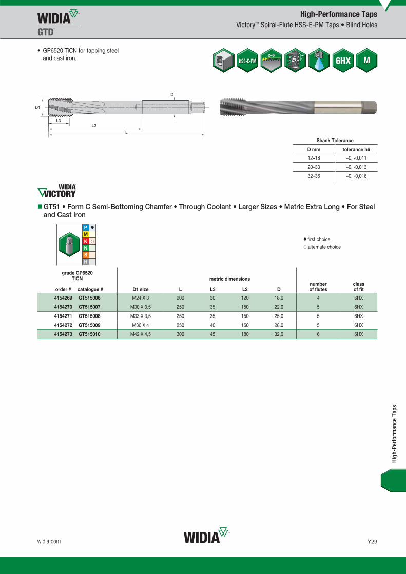
Y29
L V i WID M 16 T Y028 Y029 M i REBRANDO b 23 20159 51AM
widia.com
GP6520
High-Performance TapsVictory™ Spiral-Flute HSS-E-PM Taps • Blind Holes
Shank Tolerance
D mm tolerance h6
12–18 +0, -0,011
20–30 +0, -0,013
32–36 +0, -0,016
GT51 • Form C Semi-Bottoming Chamfer • Through Coolant • Larger Sizes • Metric Extra Long • For Steel and Cast Iron
grade GP6520TiCN
order # catalogue # D1 size L L3 L2 Dnumber of flutes
class of fit
4154269 GT515006 M24 X 3 200 30 120 18,0 4 6HX
4154270 GT515007 M30 X 3,5 250 35 150 22,0 5 6HX
4154271 GT515008 M33 X 3,5 250 35 150 25,0 5 6HX
4154272 GT515009 M36 X 4 250 40 150 28,0 5 6HX
4154273 GT515010 M42 X 4,5 300 45 180 32,0 6 6HX
High
-Per
form
ance
Tap
s
• GP6520 TiCN for tapping steel and cast iron.
� first choice� alternate choice
metric dimensions
WID_Master16_Taps_Y028_Y029_Metric_REBRAND.indd 29 10/30/15 3:04 PM

Y30
L V i WID M 16 T Y030 Y031 M i REBRAND O b 23 2015 9 51 AM
widia.com
WS32MG
High-Performance TapsVictory™ Spiral-Flute HSS-E-PM Taps • Blind Holes
GT12 • Form C Semi-Bottoming Chamfer • Metric DIN 371 and 376 • For Nickel and Nickel Alloys
grade WS32MGTiCN
order # catalogue # D1 size L L3 L2 Dnumber of flutes
dimensionstandard
class of fit
4159636 GT125001 M3 X 0,5 56 11 18 3,5 2 DIN 371 6HX
4159637 GT125002 M4 X 0,7 63 13 21 4,5 3 DIN 371 6HX
4159638 GT125003 M5 X 0,8 70 15 25 6,0 3 DIN 371 6HX
4159639 GT125004 M6 X 1 80 17 30 6,0 3 DIN 371 6HX
4159640 GT125005 M8 X 1,25 90 20 35 8,0 3 DIN 371 6HX
4159641 GT125006 M10 X 1,5 100 22 39 10,0 3 DIN 371 6HX
4159642 GT125007 M12 X 1,75 110 24 — 9,0 3 DIN 376 6HX
4159663 GT125008 M14 X 2 110 26 — 11,0 3 DIN 376 6HX
4159664 GT125009 M16 X 2 110 27 — 12,0 3 DIN 376 6HX
4159665 GT125010 M20 X 2,5 140 32 — 16,0 3 DIN 376 6HX
• WS32MG TiCN for nickel and nickel alloys.
� first choice� alternate choice
metric dimensions
Shank Tolerance
D mm tolerance h9
1–3 +0, -0,025
>3–6 +0, -0,030
>6–10 +0, -0,036
>10–18 +0, -0,043
>18–30 +0, -0,052
High
-Per
form
ance
Tap
s
WID_Master16_Taps_Y030_Y031_Metric_REBRAND.indd 30 10/30/15 3:04 PM

Y31
L V i WID M 16 T Y030 Y031 M i REBRANDO b 23 20159 51AM
widia.com
WN35MG
High-Performance TapsVictory™ Spiral-Flute HSS-E-PM Taps • Blind Holes
Shank Tolerance
D mm tolerance h9
1–3 +0, -0,025
>3–6 +0, -0,030
>6–10 +0, -0,036
>10–18 +0, -0,043
>18–30 +0, -0,052
GT16 • Form C Semi-Bottoming Chamfer • Metric DIN 371 • For Titanium and Titanium Alloys
grade WN35MGTiN/DLC
order # catalogue # D1 size L L3 L2 Dnumber of flutes
dimensionstandard
class of fit
4160437 GT165001 M3 X 0,5 56 6 18 3,5 3 DIN 371 6HX
4160438 GT165002 M4 X 0,7 63 7 21 4,5 3 DIN 371 6HX
4160439 GT165003 M5 X 0,8 70 8 25 6,0 3 DIN 371 6HX
4160440 GT165004 M6 X 1 80 10 30 6,0 3 DIN 371 6HX
4160441 GT165005 M8 X 1,25 90 14 35 8,0 3 DIN 371 6HX
4160442 GT165006 M10 X 1,5 100 16 39 10,0 3 DIN 371 6HX
4160523 GT165007 M12 X 1,75 110 18 44 12,0 3 DIN 371 6HX
High
-Per
form
ance
Tap
s
• WN35MG TiN/DLC for titanium and titanium alloys.
� first choice� alternate choice
metric dimensions
WID_Master16_Taps_Y030_Y031_Metric_REBRAND.indd 31 10/30/15 3:04 PM

Y32
L V i WID M 16 T Y032 Y033 M i REBRAND O b 23 2015 9 52 AM
widia.com
WN48EG
High-Performance TapsVictory™ Spiral-Flute HSS-E Taps • Blind Holes
Shank Tolerance
D mm tolerance h9
1–3 +0, -0,025
3,5–6 +0, -0,030
7–10 +0, -0,036
11–18 +0, -0,043
GT80 • Form C Semi-Bottoming Chamfer • Metric DIN 371 and 376 • For Aluminium
grade WN48EGDLC
order # catalogue # D1 size L L3 L2 Dnumber of flutes
dimensionstandard
class of fit
4160054 GT805001 M3 X 0,5 56 6 18 3,5 2 DIN 371 6H
4160055 GT805002 M4 X 0,7 63 7 21 4,5 2 DIN 371 6H
4160056 GT805003 M5 X 0,8 70 8 25 6,0 2 DIN 371 6H
4160057 GT805004 M6 X 1 80 10 30 6,0 2 DIN 371 6H
4160058 GT805005 M8 X 1,25 90 14 35 8,0 2 DIN 371 6H
4160059 GT805006 M10 X 1,5 100 16 39 10,0 2 DIN 371 6H
4160060 GT805007 M12 X 1,75 110 18 — 9,0 3 DIN 376 6H
4160061 GT805008 M16 X 2 110 22 — 12,0 3 DIN 376 6H
4160062 GT805009 M20 X 2,5 140 25 — 16,0 3 DIN 376 6H
High
-Per
form
ance
Tap
s
• WN48EG DLC for aluminium.
� first choice� alternate choice
metric dimensions
WID_Master16_Taps_Y032_Y033_Metric_REBRAND.indd 32 10/30/15 3:04 PM

Y33
L V i WID M 16 T Y032 Y033 M i REBRANDO b 23 20159 52AM
widia.com
WP31MG
High-Performance TapsVictory™ Spiral-Flute HSS-E-PM Taps • Blind Holes
GT02 • Form C Semi-Bottoming Chamfer • Metric DIN 371, 374, and 376 • For Hard Steel
grade WP31MGTiN
order # catalogue # D1 size L L3 L2 Dnumber of flutes
dimensionstandard
class of fit
4152638 GT025001 M3 X 0,5 56 11 18 3,5 3 DIN 371 6H
4152639 GT025002 M4 X 0,7 63 13 21 4,5 3 DIN 371 6H
4152640 GT025003 M5 X 0,8 70 15 25 6,0 3 DIN 371 6H
4152641 GT025004 M6 X 1 80 17 30 6,0 3 DIN 371 6H
4152709 GT025012 M8 X 1 90 17 — 6,0 3 DIN 374 6H
4152642 GT025005 M8 X 1,25 90 20 35 8,0 3 DIN 371 6H
4152710 GT025013 M10 X 1 90 18 — 7,0 3 DIN 374 6H
4152711 GT025014 M10 X 1,25 100 22 — 7,0 3 DIN 374 6H
4152703 GT025006 M10 X 1,5 100 22 39 10,0 3 DIN 371 6H
4152712 GT025015 M12 X 1,25 100 22 — 9,0 3 DIN 374 6H
4152713 GT025016 M12 X 1,5 100 22 — 9,0 3 DIN 374 6H
4152704 GT025007 M12 X 1,75 110 24 44 12,0 3 DIN 376 6H
4152714 GT025017 M14 X 1,5 100 22 — 11,0 3 DIN 374 6H
4152705 GT025008 M14 X 2 110 26 52 11,0 3 DIN 376 6H
4152715 GT025018 M16 X 1,5 100 22 — 12,0 3 DIN 374 6H
4152706 GT025009 M16 X 2 110 27 — 12,0 3 DIN 376 6H
4152707 GT025010 M18 X 2 125 30 — 14,0 4 DIN 376 6H
4152708 GT025011 M20 X 2,5 140 32 — 16,0 4 DIN 376 6H
• WP31MG TiN for steel 32–44 HRC.
� first choice� alternate choice
metric dimensions
Shank Tolerance
D mm tolerance h9
1–3 +0, -0,025
>3–6 +0, -0,030
>6–10 +0, -0,036
>10–18 +0, -0,043
>18–30 +0, -0,052
High
-Per
form
ance
Tap
s
WID_Master16_Taps_Y032_Y033_Metric_REBRAND.indd 33 10/30/15 3:04 PM

Y34
L V i WID M 16 T Y034 Y035 M i REBRAND O b 23 2015 9 52 AM
widia.com
WH36MG
High-Performance TapsVictory™ Spiral-Flute HSS-E-PM Taps • Blind Holes 3 x D
Shank Tolerance
D mm tolerance h9
1–3 +0, -0,025
>3–6 +0, -0,030
>6–10 +0, -0,036
>10–18 +0, -0,043
>18–30 +0, -0,052
GT04 • Form C Semi-Bottoming Chamfer • Metric DIN 371, 374, and 376 • For Hard Steel
grade WH36MGTiN+MoS2
order # catalogue # D1 size L L3 L2 Dnumber of flutes
dimensionstandard
class of fit
4158471 GT045001 M3 X 0,5 56 6 18 3,5 3 DIN 371 6H
4158472 GT045002 M4 X 0,7 63 7 21 4,5 3 DIN 371 6H
4158763 GT045003 M5 X 0,8 70 8 25 6,0 3 DIN 371 6H
4158764 GT045004 M6 X 1 80 10 30 6,0 3 DIN 371 6H
4158772 GT045012 M8 X 1 90 10 — 6,0 3 DIN 374 6H
4158765 GT045005 M8 X 1,25 90 14 35 8,0 3 DIN 371 6H
4158773 GT045013 M10 X 1 90 10 — 7,0 3 DIN 374 6H
4158774 GT045014 M10 X 1,25 100 16 — 7,0 3 DIN 374 6H
4158766 GT045006 M10 X 1,5 100 16 39 10,0 3 DIN 371 6H
4158775 GT045015 M12 X 1,25 100 15 — 9,0 4 DIN 374 6H
4158776 GT045016 M12 X 1,5 100 15 — 9,0 4 DIN 374 6H
4158767 GT045007 M12 X 1,75 110 18 — 9,0 4 DIN 376 6H
4158777 GT045017 M14 X 1,5 100 15 — 11,0 4 DIN 374 6H
4158768 GT045008 M14 X 2 110 20 — 11,0 4 DIN 376 6H
4158778 GT045018 M16 X 1,5 100 15 — 12,0 4 DIN 374 6H
4158769 GT045009 M16 X 2 110 22 — 12,0 4 DIN 376 6H
4158770 GT045010 M18 X 2,5 125 25 — 14,0 4 DIN 376 6H
4158771 GT045011 M20 X 2,5 140 25 — 16,0 4 DIN 376 6H
High
-Per
form
ance
Tap
s
• WH36MG TiAlN/MoS2 for steel 32–44 HRC (3 x D).
� first choice� alternate choice
metric dimensions
WID_Master16_Taps_Y034_Y035_Metric_REBRAND.indd 34 10/30/15 3:04 PM

Y35
L V i WID M 16 T Y034 Y035 M i REBRANDO b 23 20159 52AM
widia.com
WU41EG WP49EG
Multipurpose TapsVariTap™ Spiral-Flute HSS-E Taps • Blind Holes
VT-SFT • Form C Semi-Bottoming Chamfer • Machine Screw and Fractional • DIN 371 and 376
grade WU41EGTiN
order # catalogue #
grade WP49EGOxide
order # catalogue # D1 size L L3 L2 Dnumber of flutes
dimensionstandard
class of fit
5472587 VTSFT6005 5387487 VTSFT6005 4 - 40 56 8 18 3,5 2 DIN 371 2B
5472589 VTSFT6007 5387489 VTSFT6007 5 - 40 56 9 20 4,0 2 DIN 371 2B
5472600 VTSFT6008 5387640 VTSFT6008 6 - 32 56 9 20 4,0 2 DIN 371 2B
5472602 VTSFT6010 5387642 VTSFT6010 6 - 40 56 9 20 4,0 2 DIN 371 2B
5472603 VTSFT6011 5387643 VTSFT6011 8 - 32 63 11 21 4,5 3 DIN 371 2B
5472605 VTSFT6013 5387645 VTSFT6013 10 - 24 70 12 25 6,0 3 DIN 371 2B
5472606 VTSFT6014 5387646 VTSFT6014 10 - 32 70 12 25 6,0 3 DIN 371 2B
5472608 VTSFT6016 5387648 VTSFT6016 1/4 - 20 80 15 30 7,0 3 DIN 371 2B
5472609 VTSFT6017 5387649 VTSFT6017 1/4 - 28 80 15 30 7,0 3 DIN 371 2B
5472611 VTSFT6019 5387651 VTSFT6019 5/16 - 18 90 15 35 8,0 3 DIN 371 2B
5472612 VTSFT6020 5387652 VTSFT6020 5/16 - 24 90 15 35 8,0 3 DIN 371 2B
5472614 VTSFT6022 5387654 VTSFT6022 3/8 - 16 100 19 39 10,0 3 DIN 371 2B
5472615 VTSFT6023 5387655 VTSFT6023 3/8 - 24 100 19 39 10,0 3 DIN 371 2B
5472617 VTSFT6025 5387657 VTSFT6025 7/16 - 14 100 18 41 8,0 3 DIN 376 2B
5472618 VTSFT6026 5387658 VTSFT6026 7/16 - 20 100 18 41 8,0 3 DIN 376 2B
5472620 VTSFT6028 5387670 VTSFT6028 1/2 - 13 110 23 40 9,0 3 DIN 376 2B
5472621 VTSFT6029 5387671 VTSFT6029 1/2 - 20 110 23 40 9,0 3 DIN 376 2B
5472623 VTSFT6031 5387673 VTSFT6031 9/16 - 12 110 25 32 11,0 3 DIN 376 2B
5472624 VTSFT6032 5387674 VTSFT6032 9/16 - 18 110 25 32 11,0 3 DIN 376 2B
5472625 VTSFT6033 5387675 VTSFT6033 5/8 - 11 110 24 35 12,0 3 DIN 376 2B
• WU41EG TiN.
• WP49EG oxide.
� first choice� alternate choice
metric dimensions
Shank Tolerance
D mm tolerance h9
1–3 +0, -0,025
>3–6 +0, -0,030
>6–10 +0, -0,036
>10–18 +0, -0,043
>18–30 +0, -0,052
Mul
tipur
pose
Tap
s
(continued)
WID_Master16_Taps_Y034_Y035_Metric_REBRAND.indd 35 10/30/15 3:04 PM

Y36
L V i WID M 16 T Y036 Y037 M i REBRAND O b 23 2015 9 52 AM
widia.com
WU41EG WP49EG
Multipurpose TapsVariTap™ Spiral-Flute HSS-E Taps • Blind Holes
� first choice� alternate choice
metric dimensionsgrade WU41EG
TiN
order # catalogue #
grade WP49EGOxide
order # catalogue # D1 size L L3 L2 Dnumber of flutes
dimensionstandard
class of fit
5472626 VTSFT6034 5387676 VTSFT6034 5/8 - 18 110 24 35 12,0 3 DIN 376 2B
5472627 VTSFT6035 5387677 VTSFT6035 3/4 - 10 140 30 46 16,0 4 DIN 376 2B
5472628 VTSFT6036 5387678 VTSFT6036 3/4 - 16 140 30 46 16,0 4 DIN 376 2B
5472629 VTSFT6037 5387679 VTSFT6037 7/8 - 9 140 34 35 18,0 4 DIN 376 2B
5472630 VTSFT6038 5387700 VTSFT6038 7/8 - 14 140 34 35 18,0 4 DIN 376 2B
5472631 VTSFT6039 5387701 VTSFT6039 1 - 8 160 38 41 18,0 4 DIN 376 2B
5472632 VTSFT6040 5387702 VTSFT6040 1 - 12 160 38 41 18,0 4 DIN 376 2B
Mul
tipur
pose
Tap
s
(VT-SFT • Form C Semi-Bottoming Chamfer • Machine Screw and Fractional • DIN 371 and 376 — continued)
WID_Master16_Taps_Y036_Y037_Metric_REBRAND.indd 36 10/30/15 3:04 PM

Y37
L V i WID M 16 T Y036 Y037 M i REBRANDO b 23 20159 52AM
widia.com
WP49EG
Multipurpose TapsVariTap™ Spiral-Flute HSS-E Taps • Blind Holes
VT-SFT • Form C Semi-Bottoming Chamfer • UNJC/UNJF • Inch DIN 371 and 376
grade WP49EGOxide
order # catalogue # D1 size L L3 L2 Dnumber of flutes
dimensionstandard
class of fit
5387488 VTSFT6006 4 - 40 56 8 18 3,5 2 DIN 371 3B
5387641 VTSFT6009 6 - 32 56 9 20 4,0 2 DIN 371 3B
5387644 VTSFT6012 8 - 32 63 11 21 4,5 3 DIN 371 3B
5387647 VTSFT6015 10 - 32 70 12 25 6,0 3 DIN 371 3B
5387650 VTSFT6018 1/4 - 28 80 15 30 7,0 3 DIN 371 3B
5387653 VTSFT6021 5/16 - 24 90 15 35 8,0 3 DIN 371 3B
5387656 VTSFT6024 3/8 - 24 100 19 39 10,0 3 DIN 371 3B
5387659 VTSFT6027 7/16 - 20 100 18 41 8,0 3 DIN 376 3B
5387672 VTSFT6030 1/2 - 20 110 23 40 9,0 3 DIN 376 3B
• WP49EG oxide
� first choice� alternate choice
metric dimensions
Shank Tolerance
D mm tolerance h9
1–3 +0, -0,025
>3–6 +0, -0,030
>6–10 +0, -0,036
>10–18 +0, -0,043
>18–30 +0, -0,052
Mul
tipur
pose
Tap
s
WID_Master16_Taps_Y036_Y037_Metric_REBRAND.indd 37 10/30/15 3:04 PM

Y38
L V i WID M 16 T Y038 Y039 M i REBRAND O b 23 2015 9 52 AM
widia.com
WP42EG WU41EG WP49EG WU40EG
Multipurpose TapsVariTap™ Spiral-Flute HSS-E Taps • Blind Holes
VT-SFT • Form C Semi-Bottoming Chamfer • Metric DIN 371, 374, and 376
grade WP42EGTiCN
order # catalogue #
grade WU41EGTiN
order # catalogue #
grade WP49EGOxide
order # catalogue #
grade WU40EGBright
order # catalogue # D1 size L L3 L2 Dnumber of flutes
dimensionstandard
class of fit
5368703 VTSFT6506 5368702 VTSFT6506 5368704 VTSFT6506 5368705 VTSFT6506 M2 X 0,4 45 7 13 2,8 2 DIN 371 6H
– – 5368706 VTSFT6507 – M2 X 0,4 45 7 13 2,8 2 DIN 371 6G
– – 5368707 VTSFT6508 – M2,2 X 0,45 45 7 13 2,8 2 DIN 371 6H
– 5368708 VTSFT6509 5368709 VTSFT6509 5368720 VTSFT6509 M2,5 X 0,45 50 7 15 2,8 2 DIN 371 6H
– – 5368721 VTSFT6510 – M2,5 X 0,45 50 7 15 2,8 2 DIN 371 6G
– – 5402138 VTSFT6545 – M3 X 0,35 56 8 — 2,2 2 DIN 374 6H
– – 5368726 VTSFT6512 – M3 X 0,5 56 8 18 3,5 2 DIN 371 6G
– – 5402227 VTSFT6525 5402228 VTSFT6525 M3 X 0,5 56 8 — 2,2 2 DIN 376 6H
5368723 VTSFT6511 5368722 VTSFT6511 5368724 VTSFT6511 5368725 VTSFT6511 M3 X 0,5 56 8 18 3,5 2 DIN 371 6H
– 5368727 VTSFT6513 5368728 VTSFT6513 5368729 VTSFT6513 M3,5 X 0,6 56 9 20 4,0 2 DIN 371 6H
– – 5402139 VTSFT6546 5402180 VTSFT6546 M4 X 0,5 63 10 21 2,8 3 DIN 374 6H
– – 5368734 VTSFT6515 – M4 X 0,7 63 11 21 4,5 3 DIN 371 6G
– – 5402229 VTSFT6526 5402250 VTSFT6526 M4 X 0,7 63 10 21 2,8 3 DIN 376 6H
5368731 VTSFT6514 5368730 VTSFT6514 5368732 VTSFT6514 5368733 VTSFT6514 M4 X 0,7 63 11 21 4,5 3 DIN 371 6H
– – 5402181 VTSFT6547 5402182 VTSFT6547 M5 X 0,5 70 12 25 3,5 3 DIN 374 6H
– – 5368739 VTSFT6517 – M5 X 0,8 70 12 25 6,0 3 DIN 371 6G
– – 5402251 VTSFT6527 5402252 VTSFT6527 M5 X 0,8 70 12 25 3,5 3 DIN 376 6H
5368736 VTSFT6516 5368735 VTSFT6516 5368737 VTSFT6516 5368738 VTSFT6516 M5 X 0,8 70 12 25 6,0 3 DIN 371 6H
– – 5402183 VTSFT6548 – M6 X 0,5 80 12 30 4,5 3 DIN 374 6H
– – 5402185 VTSFT6549 5402184 VTSFT6549 M6 X 0,75 80 12 30 4,5 3 DIN 374 6H
• WP42EG TiCN
• WU41EG TiN
• WP49EG oxide
• WU40EG bright
� first choice� alternate choice
metric dimensions
Shank Tolerance
D mm tolerance h9
1–3 +0, -0,025
>3–6 +0, -0,030
>6–10 +0, -0,036
>10–18 +0, -0,043
>18–30 +0, -0,052
Mul
tipur
pose
Tap
s
(continued)
WID_Master16_Taps_Y038_Y039_Metric_REBRAND.indd 38 10/30/15 3:04 PM

Y39
L V i WID M 16 T Y038 Y039 M i REBRANDO b 23 20159 52AM
widia.com
WP42EG WU41EG WP49EG WU40EG
Multipurpose TapsVariTap™ Spiral-Flute HSS-E Taps • Blind Holes
grade WP42EGTiCN
order # catalogue #
grade WU41EGTiN
order # catalogue #
grade WP49EGOxide
order # catalogue #
grade WU40EGBright
order # catalogue # D1 size L L3 L2 Dnumber of flutes
dimensionstandard
class of fit
5368741 VTSFT6518 5368740 VTSFT6518 5368742 VTSFT6518 5368743 VTSFT6518 M6 X 1 80 12 30 6,0 3 DIN 371 6H
– – 5402253 VTSFT6528 5402254 VTSFT6528 M6 X 1 80 12 30 4,5 3 DIN 376 6H
– – 5368744 VTSFT6519 – M6 X 1 80 12 30 6,0 3 DIN 371 6G
– – 5368745 VTSFT6520 5368746 VTSFT6520 M7 X 1 80 12 30 7,0 3 DIN 371 6H
– – 5402186 VTSFT6550 5402187 VTSFT6550 M8 X 0,75 80 12 30 6,0 3 DIN 374 6H
5402188 VTSFT6551 – 5402189 VTSFT6551 5402190 VTSFT6551 M8 X 1 90 15 35 6,0 3 DIN 374 6H
– – 5368752 VTSFT6522 – M8 X 1,25 90 15 35 8,0 3 DIN 371 6G
– – 5402255 VTSFT6529 5402256 VTSFT6529 M8 X 1,25 90 15 35 6,0 3 DIN 376 6H
5368749 VTSFT6521 5368748 VTSFT6521 5368750 VTSFT6521 5368751 VTSFT6521 M8 X 1,25 90 15 35 8,0 3 DIN 371 6H
– – – 5402191 VTSFT6552 M10 X 0,75 90 15 35 7,0 3 DIN 374 6H
– – 5402192 VTSFT6553 5402193 VTSFT6553 M10 X 1 90 15 35 7,0 3 DIN 374 6H
5402194 VTSFT6554 – 5402195 VTSFT6554 5402196 VTSFT6554 M10 X 1,25 100 18 39 7,0 3 DIN 374 6H
5368754 VTSFT6523 5368753 VTSFT6523 5368755 VTSFT6523 5368756 VTSFT6523 M10 X 1,5 100 18 39 10,0 3 DIN 371 6H
– – 5368757 VTSFT6524 – M10 X 1,5 100 18 39 10,0 3 DIN 371 6G
– – 5402257 VTSFT6530 5402258 VTSFT6530 M10 X 1,5 100 18 39 7,0 3 DIN 376 6H
– – 5402197 VTSFT6555 5402198 VTSFT6555 M12 X 1 100 21 39 9,0 3 DIN 374 6H
– – 5402199 VTSFT6556 5402200 VTSFT6556 M12 X 1,25 100 21 39 9,0 3 DIN 374 6H
5402201 VTSFT6557 – 5402202 VTSFT6557 5402203 VTSFT6557 M12 X 1,5 100 21 39 9,0 3 DIN 374 6H
– – 5402263 VTSFT6532 – M12 X 1,75 110 21 44 9,0 3 DIN 376 6G
5402260 VTSFT6531 5402259 VTSFT6531 5402261 VTSFT6531 5402262 VTSFT6531 M12 X 1,75 110 21 44 9,0 3 DIN 376 6H
– – – 5402204 VTSFT6558 M14 X 1 100 21 47 11,0 3 DIN 374 6H
– – – 5402205 VTSFT6559 M14 X 1,25 100 21 47 11,0 3 DIN 374 6H
5402206 VTSFT6560 – 5402207 VTSFT6560 5402208 VTSFT6560 M14 X 1,5 100 21 47 11,0 3 DIN 374 6H
– – 5402268 VTSFT6534 – M14 X 2 110 24 52 11,0 3 DIN 376 6G
5402265 VTSFT6533 5402264 VTSFT6533 5402266 VTSFT6533 5402267 VTSFT6533 M14 X 2 110 24 52 11,0 3 DIN 376 6H
– – – 5402209 VTSFT6561 M16 X 1 100 21 46 12,0 3 DIN 374 6H
– – 5402210 VTSFT6562 5402211 VTSFT6562 M16 X 1,5 100 21 46 12,0 3 DIN 374 6H
– – 5402272 VTSFT6536 – M16 X 2 110 24 51 12,0 3 DIN 376 6G
– 5402269 VTSFT6535 5402270 VTSFT6535 5402271 VTSFT6535 M16 X 2 110 24 51 12,0 3 DIN 376 6H
– – – 5402212 VTSFT6563 M18 X 1 110 21 50 14,0 4 DIN 374 6H
– – 5402214 VTSFT6564 5402213 VTSFT6564 M18 X 1,5 110 21 50 14,0 4 DIN 374 6H
– – – 5402215 VTSFT6565 M18 X 2 125 30 58 14,0 4 DIN 374 6H
– 5402273 VTSFT6537 5402274 VTSFT6537 5402275 VTSFT6537 M18 X 2,5 125 30 58 14,0 4 DIN 376 6H
– – – 5402216 VTSFT6566 M20 X 1 125 24 56 16,0 4 DIN 374 6H
– – 5402217 VTSFT6567 5402218 VTSFT6567 M20 X 1,5 125 24 56 16,0 4 DIN 374 6H
– – – 5402219 VTSFT6568 M20 X 2 140 30 64 16,0 4 DIN 374 6H
– 5402276 VTSFT6538 5402277 VTSFT6538 5402278 VTSFT6538 M20 X 2,5 140 30 64 16,0 4 DIN 376 6H
– – 5402220 VTSFT6569 5402221 VTSFT6569 M22 X 1,5 125 24 62 18,0 4 DIN 374 6H
– – – 5402222 VTSFT6570 M22 X 2 140 30 70 18,0 4 DIN 374 6H
– 5402279 VTSFT6539 5402280 VTSFT6539 5402281 VTSFT6539 M22 X 2,5 140 30 70 18,0 4 DIN 376 6H
Mul
tipur
pose
Tap
s
(continued)
� first choice� alternate choice
metric dimensions
(VT-SFT • Form C Semi-Bottoming Chamfer • Metric DIN 371, 374, and 376 — continued)
WID_Master16_Taps_Y038_Y039_Metric_REBRAND.indd 39 10/30/15 3:04 PM

Y40
L V i WID M 16 T Y040 Y041 M i REBRAND O b 23 2015 9 52 AM
widia.com
WP42EG WU41EG WP49EG WU40EG
Multipurpose TapsVariTap™ Spiral-Flute HSS-E Taps • Blind Holes
� first choice� alternate choice
metric dimensions
grade WP42EGTiCN
order # catalogue #
grade WU41EGTiN
order # catalogue #
grade WP49EGOxide
order # catalogue #
grade WU40EGBright
order # catalogue # D1 size L L3 L2 Dnumber of flutes
dimensionstandard
class of fit
– – 5402223 VTSFT6571 5402224 VTSFT6571 M24 X 1,5 140 28 67 18,0 4 DIN 374 6H
– – – 5402225 VTSFT6572 M24 X 2 140 28 67 18,0 4 DIN 374 6H
– 5402282 VTSFT6540 5402283 VTSFT6540 5402284 VTSFT6540 M24 X 3 160 36 77 18,0 4 DIN 376 6H
– 5402285 VTSFT6541 5402286 VTSFT6541 5402287 VTSFT6541 M27 X 3 160 36 82 20,0 4 DIN 376 6H
– – – 5402226 VTSFT6573 M30 X 2 150 28 80 22,0 2 DIN 374 6H
– 5402288 VTSFT6542 5402289 VTSFT6542 5402290 VTSFT6542 M30 X 3,5 180 42 91 22,0 4 DIN 376 6H
– – 5402291 VTSFT6543 5402292 VTSFT6543 M33 X 3,5 180 42 100 25,0 4 DIN 376 6H
– – 5402293 VTSFT6544 5402294 VTSFT6544 M36 X 4 200 48 110 28,0 5 DIN 376 6H
Mul
tipur
pose
Tap
s
(VT-SFT • Form C Semi-Bottoming Chamfer • Metric DIN 371, 374, and 376 — continued)
WID_Master16_Taps_Y040_Y041_Metric_REBRAND.indd 40 10/30/15 3:04 PM

Y41
L V i WID M 16 T Y040 Y041 M i REBRANDO b 23 20159 52AM
widia.com
WP42EG WP49EG
Multipurpose TapsVariTap™ Spiral-Flute HSS-E Taps • Blind Holes
Shank Tolerance
D mm tolerance h9
1–3 +0, -0,025
>3–6 +0, -0,030
>6–10 +0, -0,036
>10–18 +0, -0,043
>18–30 +0, -0,052
VT-SFT • Form E Bottoming Chamfer • Metric DIN 371, 374, and 376
grade WP42EGTiCN
order # catalogue #
grade WP49EGOxide
order # catalogue # D1 size L L3 L2 Dnumber of flutes
dimensionstandard
class of fit
5387434 VTSFT6574 5387435 VTSFT6574 M3 X 0,5 56 8 18 3,5 2 DIN 371 6H
5387436 VTSFT6575 5387437 VTSFT6575 M4 X 0,7 63 11 21 4,5 3 DIN 371 6H
5387438 VTSFT6576 5387439 VTSFT6576 M5 X 0,8 70 12 25 6,0 3 DIN 371 6H
5387460 VTSFT6577 5387461 VTSFT6577 M6 X 1 80 12 30 6,0 3 DIN 371 6H
5387475 VTSFT6585 5387476 VTSFT6585 M8 X 1 90 15 35 6,0 3 DIN 374 6H
5387462 VTSFT6578 5387463 VTSFT6578 M8 X 1,25 90 15 35 8,0 3 DIN 371 6H
5387477 VTSFT6586 5387478 VTSFT6586 M10 X 1,25 100 18 39 7,0 3 DIN 374 6H
5387464 VTSFT6579 5387465 VTSFT6579 M10 X 1,5 100 18 39 10,0 3 DIN 371 6H
5387479 VTSFT6587 5387481 VTSFT6587 M12 X 1,5 100 21 39 9,0 3 DIN 374 6H
5387466 VTSFT6580 5387467 VTSFT6580 M12 X 1,75 110 21 44 9,0 3 DIN 376 6H
5387482 VTSFT6588 5387483 VTSFT6588 M14 X 1,5 100 21 47 11,0 3 DIN 374 6H
5387468 VTSFT6581 5387469 VTSFT6581 M14 X 2 110 24 52 11,0 3 DIN 376 6H
– 5387470 VTSFT6582 M16 X 2 110 24 51 12,0 3 DIN 376 6H
5387471 VTSFT6583 5387472 VTSFT6583 M18 X 2,5 125 30 58 14,0 4 DIN 376 6H
5387473 VTSFT6584 5387474 VTSFT6584 M20 X 2,5 140 30 64 16,0 4 DIN 376 6H
Mul
tipur
pose
Tap
s
• WP42EG TiCN
• WP49EG oxide
� first choice� alternate choice
metric dimensions
WID_Master16_Taps_Y040_Y041_Metric_REBRAND.indd 41 10/30/15 3:04 PM

Y42
L V i WID M 16 T Y042 Y043 M i REBRAND O b 30 2015 1 02 PM
widia.com
WU41EG WU40EG
3–5
Multipurpose TapsVariTap™ Spiral-Flute HSS-E Taps • Blind Holes
VT-SFT • Form C Semi-Bottoming Chamfer • Metric • JIS
grade WU41EGTiN
order # catalogue #
grade WU40EGBright
order # catalogue # D1 size L L3 L2 Dnumber of flutes
dimensionstandard
tap class
5398709 VTSFT7505 5398708 VTSFT7505 M3 X 0,5 46 11 19 4,0 2 JIS ISO 2
5398791 VTSFT7506 5398790 VTSFT7506 M4 X 0,7 52 13 21 5,0 3 JIS ISO 2
5398793 VTSFT7507 5398792 VTSFT7507 M5 X 0,8 60 16 24 5,5 3 JIS ISO 2
5398795 VTSFT7508 5398794 VTSFT7508 M6 X 1 62 19 29 6,0 3 JIS ISO 2
5398797 VTSFT7509 5398796 VTSFT7509 M8 X 1,25 70 22 37 6,2 3 JIS ISO 2
5398799 VTSFT7510 5398798 VTSFT7510 M10 X 1,5 75 24 41 7,0 3 JIS ISO 2
– 5398800 VTSFT7511 M12 X 1,25 82 29 48 8,5 3 JIS ISO 2
– 5398802 VTSFT7513 M12 X 1,5 82 29 48 8,5 3 JIS ISO 2
– 5398801 VTSFT7512 M12 X 1,75 82 29 48 8,5 3 JIS ISO 2
– 5398804 VTSFT7515 M14 X 1,5 88 30 48 10,5 3 JIS ISO 2
– 5398803 VTSFT7514 M14 X 2 88 30 48 10,5 3 JIS ISO 2
– 5398806 VTSFT7517 M16 X 1,5 95 32 52 12,5 3 JIS ISO 2
– 5398805 VTSFT7516 M16 X 2 95 32 52 12,5 3 JIS ISO 2
– 5398807 VTSFT7518 M18 X 2,5 100 37 55 14,0 4 JIS ISO 2
– 5398808 VTSFT7519 M20 X 2,5 105 37 60 15,0 4 JIS ISO 2
• WU41EG TiN
• WU40EG bright
� first choice� alternate choice
metric dimensions
Mul
tipur
pose
Tap
s
Shank Tolerance
D mm tolerance h9
1–3 +0, -0,025
>3–6 +0, -0,030
>6–10 +0, -0,036
>10–18 +0, -0,043
>18–30 +0, -0,052
WID_Master16_Taps_Y042_Y043_Metric_REBRAND.indd 42 10/30/15 3:04 PM

L V i WID M 16 T Y042 Y043 M i REBRANDO b 30 20151 02PM
WIDIA™ VariTap™
Tap into the power of the original.
A heritage of hard work, innovation, and excellence. That’s what makes an original.
Built on a 140-year legacy of providing the industry with the highest qualityperformance in taps, dies, and gages. Our history propels us to keep deliveringthe most advanced solutions.
The WIDIA VariTap is the next application of our commitment to innovation.
• Extensive range of sizes, fi ts, styles, and coatings, equipped with optimisedgeometry, offering the largest portfolio solution of multipurpose taps available.
• Capable of working with a wide variety of materials.• Long and consistent tool life leading to lower inventory costs.• Unique spiral-point geometry provides low tapping torque, while pushing chips
ahead of the tap in through holes.• Superior thread fi nish.
To learn more about the unmatched benefi ts of WIDIA VariTap, call 800.979.4342, contact your local Authorised Distributor, or visit widia.com/varitap.
WID_Master16_Taps_Y042_Y043_Metric_REBRAND.indd 43 10/30/15 3:04 PM

Y44
L V i WID M 16 T Y044 Y045 M i REBRAND N b 13 2015 9 05 AM
widia.com
Straight Flute
WIDIA-GTD™ offers a wide range of straight-fl ute options for tapping through and blind holes in:
• Cast iron.• Aluminium.
Solutions for Through and Blind Hole Applications • WIDIA-GTD™
WID_Master16_Taps_Y044_Y045_Metric_REBRAND.indd 44 11/13/15 9:40 AM

Y45
L V i WID M 16 T Y044 Y045 M i REBRANDN b 13 20159 05AM
widia.com
High-Performance Victory™ Solid Carbide Taps• Straight flute designed for outstanding tool life in cast iron, aluminium,
and hardened materials. • Manufactured with fine-grain micrograin carbide for exceptional wear life. • Ideal for long production runs where fewer tool changes mean greater
productivity. • Runs up to 4x faster and lasts up to 4x longer than conventional high-speed
steel taps. • Excellent thread quality and tap performance.
High-Performance Victory™ HSS-E-PM Taps• Straight-flute taps store chips in hole or are flushed out with internal coolant. • Manufactured from powdered metal high-speed steel coated for thread
cutting in cast iron and aluminium. • Offer performance advantages over conventional high-speed steel taps. • Long tap life at up to 50% higher tapping speed than HSS taps.
WID_Master16_Taps_Y044_Y045_Metric_REBRAND.indd 45 11/13/15 9:40 AM

Y46
L V i WID M 16 T Y046 Y047 M i REBRAND O b 23 2015 9 53 AM
widia.com
WH16PG
High-Performance TapsVictory™ Straight-Flute Carbide Taps • Blind and Through Holes
Shank Tolerance
D mm tolerance h6
1–3 +0, -0,025
3,5–6 +0, -0,030
7–10 +0, -0,036
11–18 +0, -0,043
GX10 • Form C Semi-Bottoming Chamfer • Metric DIN 371, 374, and 376 • For Hard Steel
grade WH16PGTiAlN+MoS2
order # catalogue # D1 size L L3 L2 Dnumber of flutes
dimensionstandard
class of fit
4158323 GX105001 M3 X 0,5 63 6 18 4,5 4 DIN 371 6HX
4158324 GX105002 M4 X 0,7 63 8 20 4,5 4 DIN 371 6HX
4158325 GX105003 M5 X 0,8 70 10 26 6,0 4 DIN 371 6HX
4158326 GX105004 M6 X 1 80 12 28 6,0 4 DIN 371 6HX
4158331 GX105009 M8 X 1 90 15 35 8,0 5 DIN 374 6HX
4158327 GX105005 M8 X 1,25 90 15 35 8,0 5 DIN 371 6HX
4158332 GX105010 M10 X 1 100 18 38 10,0 5 DIN 374 6HX
4158328 GX105006 M10 X 1,5 100 18 38 10,0 5 DIN 371 6HX
4158333 GX105011 M12 X 1,5 110 21 41 12,0 5 DIN 374 6HX
4158329 GX105007 M12 X 1,75 110 21 41 12,0 5 DIN 376 6HX
4158334 GX105012 M14 X 1,5 110 24 44 14,0 5 DIN 374 6HX
4158330 GX105008 M14 X 2 110 24 44 14,0 6 DIN 376 6HX
4158335 GX105013 M16 X 1,5 110 24 44 16,0 5 DIN 374 6HX
High
-Per
form
ance
Tap
s
• WH16PG TiAlN/MoS2 for steel 55–63 HRC.
� first choice� alternate choice
metric dimensions
WID_Master16_Taps_Y046_Y047_Metric_REBRAND.indd 46 10/30/15 3:04 PM

Y47
L V i WID M 16 T Y046 Y047 M i REBRANDO b 23 20159 53AM
widia.com
WK12PG
High-Performance TapsVictory™ Solid Carbide Straight-Flute Taps • Blind Holes
GX35 • Form E Bottoming Chamfer • Through Coolant M6 and Larger • Metric • For Cast Iron
grade WK12PGTiCN
order # catalogue # D1 size L L3 L2 LS Dnumber of flutes
class of fit
5551152 GX352733 M6 X 1 70 12 24 42 6,0 4 6HX
5551153 GX352734 M8 X 1,25 80 15 32 43 8,0 4 6HX
5551154 GX352735 M10 X 1,5 90 18 40 44 10,0 4 6HX
5551156 GX352738 M12 X 1,5 100 21 48 46 12,0 4 6HX
5551155 GX352737 M12 X 1,75 100 21 48 46 12,0 4 6HX
5551159 GX352740 M14 X 1,5 110 24 56 52 12,0 4 6HX
5551157 GX352739 M14 X 2 110 24 56 52 12,0 4 6HX
5551160 GX352741 M16 X 2 110 24 64 44 14,0 4 6HX
• WK12PG TiCN for cast iron.
� first choice� alternate choice
metric dimensions
Shank Tolerance
D tolerance h6
6 +0, -0,008
8–10 +0, -0,009
12–16 +0, -0,011
High
-Per
form
ance
Tap
s
WID_Master16_Taps_Y046_Y047_Metric_REBRAND.indd 47 10/30/15 3:04 PM

Y48
L V i WID M 16 T Y048 Y049 M i REBRAND O b 23 2015 9 53 AM
widia.com
WK12PG
High-Performance TapsVictory™ Solid Carbide Straight-Flute Taps • Blind Holes
Shank Tolerance
D mm tolerance h6
6 +0, -0,008
8–10 +0, -0,009
12–16 +0, -0,011
GX35 • Form E Bottoming Chamfer • Through Coolant • Metric • For Cast Iron
grade WK12PGTiCN
order # catalogue # D1 size L L3 L2 Dnumber of flutes
class of fit
5520825 GX355006 M6 X 1 80 10 30 6,0 4 6HX
5520826 GX355007 M7 X 1 80 10 30 7,0 4 6HX
5520827 GX355008 M8 X 1,25 90 13 35 8,0 4 6HX
5520828 GX355009 M9 X 1,25 90 13 35 9,0 4 6HX
5520830 GX355101 M10 X 1 90 10 35 7,0 4 6HX
5520831 GX355102 M10 X 1,25 100 15 39 7,0 4 6HX
5520829 GX355010 M10 X 1,5 100 15 39 10,0 4 6HX
5520834 GX355121 M12 X 1,25 100 15 39 9,0 4 6HX
5520835 GX355122 M12 X 1,50 100 15 39 9,0 4 6HX
5520833 GX355012 M12 X 1,75 110 18 44 9,0 4 6HX
5520837 GX355141 M14 X 1,25 100 15 47 11,0 4 6HX
5520838 GX355142 M14 X 1,5 100 15 47 11,0 4 6HX
5520836 GX355014 M14 X 2 110 20 52 11,0 4 6HX
High
-Per
form
ance
Tap
s
� first choice� alternate choice
• WK12PG TiCN for cast iron.
metric dimensions
WID_Master16_Taps_Y048_Y049_Metric_REBRAND.indd 48 10/30/15 3:04 PM

Y49
L V i WID M 16 T Y048 Y049 M i REBRANDO b 23 20159 53AM
widia.com
WN14PG
High-Performance TapsVictory™ Solid Carbide Straight-Flute Taps • Blind Holes
GX47 • Form E Bottoming Chamfer • Through Coolant • Metric • For Aluminium
grade WN14PGTiN+CrC/C
order # catalogue # D1 size L L3 L2 Dnumber of flutes
class of fit
5520839 GX475006 M6 X 1 80 10 30 6,0 3 6HX
5520840 GX475008 M8 X 1,25 90 10 35 8,0 3 6HX
5520841 GX475010 M10 X 1,5 100 15 39 10,0 3 6HX
• WN14PG TiN + CrC/C for aluminium.
� first choice� alternate choice
High
-Per
form
ance
Tap
s
Shank Tolerance
D tolerance h6
6 +0, -0,008
8–10 +0, -0,009
12–16 +0, -0,011
metric dimensions
WID_Master16_Taps_Y048_Y049_Metric_REBRAND.indd 49 10/30/15 3:04 PM
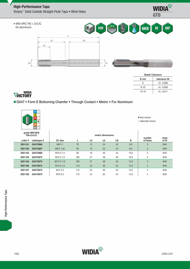
Y50
L V i WID M 16 T Y050 Y051 M i REBRAND O b 23 2015 9 53 AM
widia.com
WN14PG
High-Performance TapsVictory™ Solid Carbide Straight-Flute Taps • Blind Holes
Shank Tolerance
D mm tolerance h6
6 +0, -0,008
8–10 +0, -0,009
12–16 +0, -0,011
GX47 • Form E Bottoming Chamfer • Through Coolant • Metric • For Aluminium
grade WN14PGTiN+CrC/C
order # catalogue # D1 size L L3 L2 LS Dnumber of flutes
class of fit
5551161 GX472866 M6 X 1 70 12 24 42 6,0 3 6HX
5551162 GX472867 M8 X 1,25 80 15 32 43 8,0 3 6HX
5551163 GX472868 M10 X 1,5 90 18 40 44 10,0 3 6HX
5551164 GX472872 M12 X 1,5 100 21 48 46 12,0 3 6HX
5551165 GX472870 M12 X 1,75 100 21 48 46 12,0 3 6HX
5551166 GX472874 M14 X 1,5 110 24 56 52 12,0 4 6HX
5551167 GX472873 M14 X 2 110 24 56 52 12,0 4 6HX
5551168 GX472875 M16 X 2 110 24 64 44 14,0 4 6HX
High
-Per
form
ance
Tap
s
• WN14PG TiN + CrC/C for aluminium.
� first choice� alternate choice
metric dimensions
WID_Master16_Taps_Y050_Y051_Metric_REBRAND.indd 50 10/30/15 3:05 PM

Y51
L V i WID M 16 T Y050 Y051 M i REBRANDO b 23 20159 53AM
widia.com
WK12PG
High-Performance TapsVictory™ Solid Carbide Straight-Flute Taps • Blind Holes
GX50 • Form C Semi-Bottoming Chamfer • Through Coolant M6 and Larger • Metric • For Cast Iron
grade WK12PGTiCN
order # catalogue # D1 size L L3 L2 Dnumber of flutes
class of fit
5520817 GX505004 M4 X 0,7 63 10 21 4,5 3 6HX
5520818 GX505005 M5 X 0,8 70 10 25 6,0 3 6HX
5520819 GX505006 M6 X 1 80 10 30 6,0 4 6HX
5520820 GX505008 M8 X 1,25 90 13 35 8,0 4 6HX
5520822 GX505010 M10 X 1,5 100 15 39 10,0 4 6HX
5520823 GX505012 M12 X 1,75 110 18 44 9,0 4 6HX
5520824 GX505014 M14 X 2 110 20 52 11,0 4 6HX
• WK12PG TiCN for cast iron.
� first choice� alternate choice
High
-Per
form
ance
Tap
s
Shank Tolerance
D mm tolerance h6
6 +0, -0,008
8–10 +0, -0,009
12–16 +0, -0,011
metric dimensions
WID_Master16_Taps_Y050_Y051_Metric_REBRAND.indd 51 10/30/15 3:05 PM

Y52
L V i WID M 16 T Y052 Y053 M i REBRAND O b 23 2015 9 53 AM
widia.com
GP6520
High-Performance TapsVictory™ Straight-Flute HSS-E-PM Taps • Through and Blind Holes
GT40 • Form C Semi-Bottoming Chamfer • Metric DIN 371, 374, and 376 • For Cast Iron and Cast Aluminium
grade GP6520TiCN
order # catalogue # D1 size L L3 L2 Dnumber of flutes
dimensionstandard
class of fit
4033699 GT405001 M4 X 0,7 63 10 21 4,5 3 DIN 371 6HX
4033700 GT405002 M5 X 0,8 70 10 25 6,0 3 DIN 371 6HX
4033701 GT405003 M6 X 1 80 10 30 6,0 4 DIN 371 6HX
4033702 GT405004 M8 X 1,25 90 13 35 8,0 4 DIN 371 6HX
4033753 GT405005 M10 X 1,5 100 15 39 10,0 4 DIN 371 6HX
5408066 GT405057 M12 X 1,5 100 15 39 9,0 4 DIN 374 6HX
4033754 GT405006 M12 X 1,75 110 18 44 9,0 4 DIN 376 6HX
5408067 GT405058 M14 X 1,5 100 15 47 11,0 4 DIN 374 6HX
4033755 GT405007 M14 X 2 110 20 52 11,0 4 DIN 376 6HX
5408068 GT405059 M16 X 1,5 100 15 46 12,0 4 DIN 374 6HX
4033756 GT405008 M16 X 2 110 20 51 12,0 4 DIN 376 6HX
4033757 GT405009 M18 X 2,5 125 25 58 14,0 4 DIN 376 6HX
4033758 GT405010 M20 X 2,5 140 25 64 16,0 4 DIN 376 6HX
4033759 GT405011 M22 X 2,5 140 25 70 18,0 4 DIN 376 6HX
• GP6520 TiCN for cast iron and cast aluminium.
� first choice� alternate choice
metric dimensions
Shank Tolerance
D mm tolerance h6
>3–6 +0, -0,008
>6–10 +0, -0,009
>10–18 +0, -0,011
>18–30 +0, -0,013
>30–50 +0, -0,016
High
-Per
form
ance
Tap
s
WID_Master16_Taps_Y052_Y053_Metric_REBRAND.indd 52 10/30/15 3:05 PM

Y53
L V i WID M 16 T Y052 Y053 M i REBRANDO b 23 20159 53AM
widia.com
GP6520
High-Performance TapsVictory™ Straight-Flute HSS-E-PM Taps • Through and Blind Holes
GT41 • Form C Semi-Bottoming Chamfer • Through Coolant • Metric DIN 371, 374, and 376 • For Cast Iron and Cast Aluminium
grade GP6520TiCN
order # catalogue # D1 size L L3 L2 Dnumber of flutes
dimensionstandard
class of fit
4033659 GT415001 M4 X 0,7 63 10 21 4,5 3 DIN 371 6HX
4033660 GT415002 M5 X 0,8 70 10 25 6,0 3 DIN 371 6HX
4033661 GT415003 M6 X 1 80 10 30 6,0 4 DIN 371 6HX
4033662 GT415004 M8 X 1,25 90 13 35 8,0 4 DIN 371 6HX
4033813 GT415005 M10 X 1,5 100 15 39 10,0 4 DIN 371 6HX
5408069 GT415021 M12 X 1,5 100 15 39 9,0 4 DIN 374 6HX
4033814 GT415006 M12 X 1,75 110 18 44 9,0 4 DIN 376 6HX
5408400 GT415022 M14 X 1,5 100 15 47 11,0 4 DIN 374 6HX
4033815 GT415007 M14 X 2 110 20 52 11,0 4 DIN 376 6HX
5408401 GT415023 M16 X 1,5 100 15 46 12,0 4 DIN 374 6HX
4033816 GT415008 M16 X 2 110 20 51 12,0 4 DIN 376 6HX
4033817 GT415009 M18 X 2,5 125 25 58 14,0 4 DIN 376 6HX
4033818 GT415010 M20 X 2,5 140 25 64 16,0 4 DIN 376 6HX
• GP6520 TiCN for cast iron and cast aluminium.
� first choice� alternate choice
metric dimensions
Shank Tolerance
D mm tolerance h6
>3–6 +0, -0,008
>6–10 +0, -0,009
>10–18 +0, -0,011
>18–30 +0, -0,013
>30–50 +0, -0,016
High
-Per
form
ance
Tap
s
WID_Master16_Taps_Y052_Y053_Metric_REBRAND.indd 53 10/30/15 3:05 PM

Y54
L V i WID M 16 T Y054 Y055 M i REBRAND O b 23 2015 9 53 AM
widia.com
GP6520
High-Performance TapsVictory™ Straight-Flute HSS-E-PM Taps • Threading Close to the Bottom in Blind Holes
Shank Tolerance
D mm tolerance h6
>3–6 +0, -0,008
>6–10 +0, -0,009
>10–18 +0, -0,011
>18–30 +0, -0,013
>30–50 +0, -0,016
GT42 • Form E Bottoming Chamfer • Metric DIN 371, 374, and 376 • For Cast Iron and Cast Aluminium
grade GP6520TiCN
order # catalogue # D1 size L L3 L2 Dnumber of flutes
dimensionstandard
class of fit
4154274 GT425001 M5 X 0,8 70 10 25 6,0 3 DIN 371 6HX
4154275 GT425002 M6 X 1 80 10 30 6,0 4 DIN 371 6HX
4154276 GT425003 M8 X 1,25 90 13 35 8,0 4 DIN 371 6HX
4154277 GT425004 M10 X 1,5 100 15 39 10,0 4 DIN 371 6HX
4154280 GT425007 M12 X 1,5 100 15 39 9,0 4 DIN 374 6HX
4154278 GT425005 M12 X 1,75 110 18 44 9,0 4 DIN 376 6HX
4154281 GT425008 M14 X 1,5 100 15 47 11,0 4 DIN 374 6HX
4154279 GT425006 M14 X 2 110 20 52 11,0 4 DIN 376 6HX
4154282 GT425009 M16 X 1,5 100 15 46 12,0 4 DIN 374 6HX
5408402 GT425010 M16 X 2 110 20 51 12,0 4 DIN 376 6HX
5408403 GT425011 M18 X 2,5 125 25 58 14,0 4 DIN 376 6HX
5408404 GT425012 M20 X 2,5 140 25 64 16,0 4 DIN 376 6HX
High
-Per
form
ance
Tap
s
• GP6520 TiCN for cast iron and cast aluminium.
� first choice� alternate choice
metric dimensions
WID_Master16_Taps_Y054_Y055_Metric_REBRAND.indd 54 10/30/15 3:05 PM

Y55
L V i WID M 16 T Y054 Y055 M i REBRANDO b 23 20159 53AM
widia.com
GP6520
High-Performance TapsVictory™ Straight-Flute HSS-E-PM Taps • Threading Close to the Bottom in Blind Holes
GT43 • Form E Bottoming Chamfer • Through Coolant • Metric DIN 371, 374, and 376 • For Cast Iron and Cast Aluminium
grade GP6520TiCN
order # catalogue # D1 size L L3 L2 Dnumber of flutes
dimensionstandard
class of fit
4154283 GT435001 M5 X 0,8 70 10 25 6,0 3 DIN 371 6HX
4154284 GT435002 M6 X 1 80 10 30 6,0 4 DIN 371 6HX
4154285 GT435003 M8 X 1,25 90 13 35 8,0 4 DIN 371 6HX
4154286 GT435004 M10 X 1,5 100 15 39 10,0 4 DIN 371 6HX
4154289 GT435007 M12 X 1,5 100 15 39 9,0 4 DIN 374 6HX
4154287 GT435005 M12 X 1,75 110 18 44 9,0 4 DIN 376 6HX
4154290 GT435008 M14 X 1,5 100 15 47 11,0 4 DIN 374 6HX
4154288 GT435006 M14 X 2 110 20 52 11,0 4 DIN 376 6HX
4154291 GT435009 M16 X 1,5 100 15 46 12,0 4 DIN 374 6HX
5408405 GT435010 M16 X 2 110 20 51 12,0 4 DIN 376 6HX
5408406 GT435011 M18 X 2,5 125 25 58 14,0 4 DIN 376 6HX
5408407 GT435012 M20 X 2,5 140 25 64 16,0 4 DIN 376 6HX
• GP6520 TiCN for cast iron and cast aluminium.
� first choice� alternate choice
metric dimensions
High
-Per
form
ance
Tap
s
Shank Tolerance
D mm tolerance h6
>3–6 +0, -0,008
>6–10 +0, -0,009
>10–18 +0, -0,011
>18–30 +0, -0,013
>30–50 +0, -0,016
WID_Master16_Taps_Y054_Y055_Metric_REBRAND.indd 55 10/30/15 3:05 PM

Y56
L V i WID M 16 T Y056 Y057 M i REBRAND N b 10 2015 2 04 PM
widia.com
WS32MG
High-Performance TapsVictory™ Straight-Flute HSS-E-PM Taps • Blind and Through Holes
Shank Tolerance
D mm tolerance h9
1–3 +0, -0,025
>3–6 +0, -0,030
>6–10 +0, -0,036
>10–18 +0, -0,043
>18–30 +0, -0,052
GT06 • Form C Semi-Bottoming Chamfer • Metric DIN 371, 374, and 376 • For Hard Steel
grade WS32MGTiCN
order # catalogue # D1 size L L3 L2 Dnumber of flutes
dimensionstandard
class of fit
4159915 GT065003 M6 X 1 80 10 30 6,0 4 DIN 371 6HX
4159918 GT065006 M8 X 1 90 10 35 8,0 5 DIN 374 6HX
4159913 GT065001 M8 X 1,25 90 14 35 8,0 5 DIN 371 6HX
4159919 GT065007 M10 X 1 90 10 35 10,0 5 DIN 374 6HX
4159914 GT065002 M10 X 1,5 100 16 39 10,0 5 DIN 371 6HX
4159920 GT065008 M12 X 1,5 100 15 — 9,0 5 DIN 374 6HX
4159916 GT065004 M12 X 1,75 110 18 — 9,0 5 DIN 376 6HX
4159921 GT065009 M14 X 1,5 100 15 — 11,0 6 DIN 374 6HX
4159922 GT065010 M16 X 1,5 100 15 — 12,0 6 DIN 374 6HX
4159917 GT065005 M16 X 2 110 22 — 12,0 6 DIN 376 6HX
High
-Per
form
ance
Tap
s
• WS32MG TiCN for steel 44–55 HRC.
� first choice� alternate choice
metric dimensions
WID_Master16_Taps_Y056_Y057_Metric_REBRAND.indd 56 11/10/15 2:22 PM

Being as productive and profi table as possible is your fundamental goal. With the addition of NOVO™ to your team,
your goal can be achieved. NOVO possesses powerful digital tools that link together process planning, inventory
availability and purchase, cost-per-part management, and productivity improvements.
NOVO can ensure you have the right tools on your machines, in the right sequence. Resulting in fl awless execution
that accelerates every job, and maximises every shift. widia.com/novo
NOVO KNOWS ART TO PART TO PROFIT
01
WID_Master16_Taps_Y056_Y057_Metric_REBRAND.indd 57 11/10/15 2:22 PM

Y58
L V i WID M 16 T Y058 Y059 M i REBRAND N b 13 2015 9 08 AM
widia.com
WIDIA-GTD™ offers a wide range of forming tap options for tapping through and blind holes in:
• Steel and steel alloys.• Stainless steel.• Aluminium.
Forming Taps
Solutions for Forming Threads in Through and Blind Hole Applications • WIDIA-GTD™
WID_Master16_Taps_Y058_Y059_Metric_REBRAND.indd 58 11/13/15 9:40 AM

Y59
L V i WID M 16 T Y058 Y059 M i REBRANDN b 13 20159 08AM
widia.com
High-Performance Victory™ Solid Carbide Taps• Advanced forming geometries designed for superior tap performance
in aluminium. • Manufactured with fine-grain micrograin carbide for exceptional wear life. • Ideal for long production runs where fewer tool changes mean greater
productivity. • Runs up to 4x faster and lasts up to 4x longer than conventional
high-speed steel taps. • Excellent thread quality and tap performance.
High-Performance Victory™ HSS-E-PM Taps• Manufactured from powdered metal high-speed steel coated for thread
forming in steel, stainless steel, and aluminium. • High hardness provides superior wear resistance. • Offer performance advantages over conventional high-speed steel taps. • Long tap life at up to 50% higher tapping speed than HSS taps.
WID_Master16_Taps_Y058_Y059_Metric_REBRAND.indd 59 11/13/15 9:40 AM

Y60
L V i WID M 16 T Y060 Y061 M i REBRAND O b 23 2015 9 54 AM
widia.com
WN14PG
High-Performance TapsVictory™ Solid Carbide Forming Taps • Blind Holes
Shank Tolerance
D mm tolerance h6
6 +0, -0,008
8–10 +0, -0,009
12–16 +0, -0,011
GX49 • Form E Bottoming Entry Taper • Through Coolant • Metric • For Aluminium
grade WN14PGTiN+CrC/C
order # catalogue # D1 size L L3 L2 Dnumber of
lube groovesclass of fit
5520842 GX495006 M6 X 1 80 10 30 6,0 2 6HX
5520843 GX495008 M8 X 1,25 90 13 35 8,0 2 6HX
5520844 GX495010 M10 X 1,5 100 15 39 10,0 3 6HX
High
-Per
form
ance
Tap
s
� first choice� alternate choice
• WN14PG TiN + CrC/C for aluminium.
metric dimensions
WID_Master16_Taps_Y060_Y061_Metric_REBRAND.indd 60 10/30/15 3:05 PM

Y61
L V i WID M 16 T Y060 Y061 M i REBRANDO b 23 20159 54AM
widia.com
WN14PG
High-Performance TapsVictory™ Solid Carbide Forming Taps • Blind Holes
GX49 • Form E Bottoming Entry Taper • Through Coolant • Metric • For Aluminium
grade WN14PGTiN+CrC/C
order # catalogue # D1 size L L3 L2 LS Dnumber of
lube groovesclass of fit
5551169 GX492908 M6 X 1 70 8 24 42 6,0 2 6HX
5551170 GX492909 M8 X 1,25 80 10 32 43 8,0 2 6HX
5551171 GX492911 M10 X 1,5 90 12 40 44 10,0 3 6HX
5551173 GX492915 M12 X 1,5 100 14 48 46 12,0 3 6HX
5551172 GX492914 M12 X 1,75 100 14 48 46 12,0 3 6HX
• WN14PG TiN + CrC/C for aluminium.
� first choice� alternate choice
metric dimensions
Shank Tolerance
D tolerance h6
6 +0, -0,008
8–10 +0, -0,009
12–16 +0, -0,011
High
-Per
form
ance
Tap
s
WID_Master16_Taps_Y060_Y061_Metric_REBRAND.indd 61 10/30/15 3:05 PM

Y62
L V i WID M 16 T Y062 Y063 M i REBRAND O b 23 2015 9 54 AM
widia.com
WP31MG WN38MG
High-Performance TapsVictory™ Forming Taps HSS-E-PM • Blind and Through Holes
Shank Tolerance
D mm tolerance h9
1–3 +0, -0,025
>3–6 +0, -0,030
>6–10 +0, -0,036
>10–18 +0, -0,043
>18–30 +0, -0,052
GT22 • Form C Semi-Bottoming Entry Taper • Metric DIN 2174 • For Steel and Aluminium
grade WP31MGTiN
order # catalogue #
grade WN38MGDLC
order # catalogue # D1 size L L3 L2 Ddimensionstandard
class of fit
4158495 GT225016 4154671 GT225001 M3 X 0,5 56 6 18 3,5 DIN 2174 6HX
4158496 GT225017 4154672 GT225002 M4 X 0,7 63 7 21 4,5 DIN 2174 6HX
4158497 GT225018 4154673 GT225003 M5 X 0,8 70 8 25 6,0 DIN 2174 6HX
4158498 GT225019 4154674 GT225004 M6 X 1 80 10 30 6,0 DIN 2174 6HX
4158513 GT225024 4154679 GT225009 M8 X 1 90 10 35 8,0 DIN 2174 6HX
4158499 GT225020 4154675 GT225005 M8 X 1,25 90 14 35 8,0 DIN 2174 6HX
4158514 GT225025 4154680 GT225010 M10 X 1 90 10 35 10,0 DIN 2174 6HX
4158515 GT225026 4154681 GT225011 M10 X 1,25 100 16 39 10,0 DIN 2174 6HX
4158500 GT225021 4154676 GT225006 M10 X 1,5 100 16 39 10,0 DIN 2174 6HX
4158516 GT225027 4154682 GT225012 M12 X 1,25 100 15 — 9,0 DIN 2174 6HX
4158517 GT225028 4154683 GT225013 M12 X 1,5 100 15 — 9,0 DIN 2174 6HX
4158501 GT225022 4154677 GT225007 M12 X 1,75 110 18 — 9,0 DIN 2174 6HX
4158518 GT225029 4154684 GT225014 M14 X 1,5 100 15 — 11,0 DIN 2174 6HX
4158519 GT225030 4154685 GT225015 M16 X 1,5 100 15 — 12,0 DIN 2174 6HX
4158502 GT225023 4154678 GT225008 M16 X 2 110 22 — 12,0 DIN 2174 6HX
High
-Per
form
ance
Tap
s
• WP31MG TiN for steel.
• WN38MG DLC for aluminium.
� first choice� alternate choice
metric dimensions
WID_Master16_Taps_Y062_Y063_Metric_REBRAND.indd 62 10/30/15 3:05 PM

Y63
L V i WID M 16 T Y062 Y063 M i REBRANDO b 23 20159 54AM
widia.com
WP31MG WN38MG
High-Performance TapsVictory™ Forming Taps HSS-E-PM • Blind and Through Holes
GT23 • Form C Semi-Bottoming Entry Taper • Through Coolant • Metric DIN 2174 • For Steel and Aluminium
grade WP31MGTiN
order # catalogue #
grade WN38MGDLC
order # catalogue # D1 size L L3 L2 Ddimensionstandard
class of fit
4159965 GT235012 4159522 GT235001 M5 X 0,8 70 8 25 6,0 DIN 2174 6HX
4159966 GT235013 4159644 GT235002 M6 X 1 80 10 30 6,0 DIN 2174 6HX
4159971 GT235018 4159649 GT235007 M8 X 1 90 10 35 8,0 DIN 2174 6HX
4159967 GT235014 4159645 GT235003 M8 X 1,25 90 14 35 8,0 DIN 2174 6HX
4159972 GT235019 4159650 GT235008 M10 X 1 90 10 35 10,0 DIN 2174 6HX
4159968 GT235015 4159646 GT235004 M10 X 1,5 100 16 39 10,0 DIN 2174 6HX
4159993 GT235020 4159651 GT235009 M12 X 1,5 100 15 — 9,0 DIN 2174 6HX
4159969 GT235016 4159647 GT235005 M12 X 1,75 110 18 — 9,0 DIN 2174 6HX
4159994 GT235021 4159652 GT235010 M14 X 1,5 100 15 — 11,0 DIN 2174 6HX
4159995 GT235022 4159653 GT235011 M16 X 1,5 100 15 — 12,0 DIN 2174 6HX
4159970 GT235017 4159648 GT235006 M16 X 2 110 22 — 12,0 DIN 2174 6HX
• WP31MG TiN for steel.
• WN38MG DLC for aluminium.
� first choice� alternate choice
metric dimensions
Shank Tolerance
D mm tolerance h9
1–3 +0, -0,025
>3–6 +0, -0,030
>6–10 +0, -0,036
>10–18 +0, -0,043
>18–30 +0, -0,052
High
-Per
form
ance
Tap
s
WID_Master16_Taps_Y062_Y063_Metric_REBRAND.indd 63 10/30/15 3:05 PM

Y64 widia.com
Our solid thread mills are designed to be the highest quality thread milling solution.
• Cut up to 63 HRC. • Improved overall thread quality.
Thread Mills
Thread Mills •
WIDIA-GTD™
Optimised fl ute designBetter chip evacuation.
Carbide substrateHigher heat resistance,higher speed.
Cylindrical h6 shankLow runout, higherquality threads.
Various multilayer coatingsExtremely high wear resistance,longer tool life.
WID_Master16_Taps_Y064_Y065_Metric_REBRAND.indd 64 2/15/16 11:35 AM

Y65widia.com
Unmatched Capabilities• Capable of easily cutting most difficult materials. • Carbide grades make threading easier and reduce machining times. • High-quality internal and external threading on 3-axis CNC machines. • Thread mills make interrupted cuts and short chips. • Design offers a range of benefits to improve overall thread quality. • Short, easily evacuated chips generate less heat and friction, so there
is a lower risk of damage to threading.
Choose WIDIA-GTD™ Thread Mills• Greater versatility than competitive products. • Optimum surface quality for an excellent end product. • Designed to eliminate chipping issues. • No need to reverse the spindle. • Fewer machining problems means more production safety.
WID_Master16_Taps_Y064_Y065_Metric_REBRAND.indd 65 11/11/15 8:59 AM

Y66
L V i WID M 16 T Y066 Y067 M i REBRAND O b 23 2015 9 54 AM
widia.com
size range (inch and metric)
GTM Series Solid Thread Milling • Metricseries
size min–max hole operation coolant grade shank
GTM11 M3–M20 WU13PV 6535 HA
GTM21 M5–M16 WU12PV 6535 HA
GTM31 M4–M16 WU12PV 6535 HA
GTM41 M6–M24 WU16PV 6535 HA
GTM41LH M6–M12 WU16PV 6535 HA
Good
Better
Best
Victory™ GTM Series HP Solid Carbide Thread Mills • Metric
High-Performance Thread MillsSelection Guide • Solid Carbide Thread Mills
size range (inch and metric)
GTM Series Solid Thread Milling • Inchseries
size min–max hole operation coolant grade shank
GTM21 #10–5/8" WU12PV 6535 HA
GTM31 1/4–5/8" WU12PV 6535 HA
GTM41 1/4–3/4" WU16PV 6535 HA
Good
Better
Best
Victory GTM Series HP Solid Carbide Thread Mills • Inch
High
-Per
form
ance
Thr
ead
Mill
s
WID_Master16_Taps_Y066_Y067_Metric_REBRAND.indd 66 10/30/15 3:05 PM

Y67
L V i WID M 16 T Y066 Y067 M i REBRANDO b 23 20159 54AM
widia.com
Y70 Y77
Y72 Y77
Y74 Y78
Y69 Y77
Y71 Y77
Y73 Y77
Y75 Y78
Y76 Y78
P M K N S H
page(s)
recommended cutting
parameters
1, 2, 3, 4, 6, 7
5, 9, 10, 11 12, 13.1 13.2 14.1, 14.2,
14.3, 14.415, 16,
17, 18, 19 20 21 22, 23, 24, 25
26, 27, 28 31, 32 33, 34,
35 36 3738.1, 38.2, 40.1, 40.2,
41.1
39.1, 41.2
Stee
l <
35 H
RC
Stee
l 36
–48
HRC
PH a
nd F
errit
ic
Stai
nles
s St
eel
<35
HRC
PH a
nd F
errit
ic
Stai
nles
s St
eel
>35
HRC
Stai
nles
s St
eel
Cast
Iron
Wro
ught
Al
umin
ium
Cast
Al
umin
ium
Copp
er,
Copp
er A
lloys
Iron
Base
d
Coba
lt Ba
sed
Nick
el B
ased
Tita
nium
Allo
ys
Hard
ened
Ste
els
49–5
5 HR
C
Hard
ened
Ste
els
56–6
8 HR
C
High-Performance Thread MillsSelection Guide • Solid Carbide Thread Mills
High
-Per
form
ance
Thr
ead
Mill
s
WID_Master16_Taps_Y066_Y067_Metric_REBRAND.indd 67 10/30/15 3:05 PM

Y68
L V i WID M 16 T Y068 Y069 M i REBRAND O b 23 2015 9 54 AM
widia.com
WU
12P
V
Coated carbide. PVD fi ne-grain carbide substrate with high-hardness TiCN coating. Universal grade for thread milling most materials.
P
M
K
N
S
P Steel
M Stainless Steel
K Cast Iron
N Non-Ferrous
S High-Temp Alloys
H Hardened Materials
Coatings are designed for optimised tapping performance in specifi c materials.
Gra
de
WU
13P
V
Coated carbide. PVD carbide substrate with heat-resistant TiAlN coating. Universal grade for thread milling most materials.
P
M
K
N
S
WU
16P
V Coated carbide. PVD two-layer coating with heat-resistant TiAlN base layer and low-friction MoS2 top layer over carbide substrate. Use for thread milling most materials, including high-hardness materials.
P
M
K
N
S
H
High-Performance Thread Mills Grades and Grade Descriptions
wear resistance
toughness
Coating Grade Description 05 10 15 20 25 30 35 40 45
WID_Master16_Taps_Y068_Y069_Metric_REBRAND.indd 68 10/30/15 3:05 PM

Y69
L V i WID M 16 T Y068 Y069 M i REBRANDO b 23 20159 54AM
widia.com
WU13PV
High-Performance Thread MillsVictory™ Solid Carbide Thread Mills • Blind and Through Holes
GTM11 • Through Coolant • Metric and Metric Fine
grade WU13PVTiAlN
order # catalogue # D1 size D1 Ap1 max L LS Dcutting edges
4138391 GTM115001 M3X0.5 2,4 6 42 28 4,0 3
4138502 GTM115012 M4X0.5 3,4 8 55 36 6,0 3
4138392 GTM115002 M4X0.7 3,2 9 55 36 6,0 3
4138503 GTM115013 M5X0.5 4,3 10 55 36 6,0 3
4138493 GTM115003 M5X0.8 4,0 11 55 36 6,0 3
4138504 GTM115014 M6X0.75 5,0 12 55 36 6,0 3
4138494 GTM115004 M6X1 4,8 12 55 36 6,0 3
4138505 GTM115015 M8X0.75 5,9 17 63 36 6,0 3
4138506 GTM115016 M8X1 5,9 16 63 36 6,0 3
4138495 GTM115005 M8X1.25 5,9 17 63 36 6,0 3
4138507 GTM115017 M10X1 7,9 20 70 36 8,0 3
4138496 GTM115006 M10X1.5 7,9 20 70 36 8,0 3
4138508 GTM115018 M12X1 9,9 24 80 40 10,0 4
4138509 GTM115019 M12X1.5 9,9 25 80 40 10,0 4
4138497 GTM115007 M12X1.75 9,9 25 80 40 10,0 4
4138510 GTM115020 M14X1.5 9,9 29 80 40 10,0 4
4138498 GTM115008 M14X2 11,6 29 90 45 12,0 4
4138511 GTM115021 M16X1.5 11,9 32 90 45 12,0 4
4138499 GTM115009 M16X2 11,9 33 90 45 12,0 4
4138512 GTM115022 M18X1.5 13,9 37 90 45 14,0 4
4138500 GTM115010 M18X2.5 13,9 39 90 45 14,0 4
4138513 GTM115023 M20X1.5 13,9 41 90 45 14,0 4
4138501 GTM115011 M20X2.5 13,9 41 90 45 14,0 4
� first choice� alternate choice
metric dimensions
Shank Tolerance
D mm tolerance h6
6 +0, -0,008
8–10 +0, -0,009
12–18 +0, -0,011
20–30 +0, -0,013
High
-Per
form
ance
Thr
ead
Mill
s
WID_Master16_Taps_Y068_Y069_Metric_REBRAND.indd 69 10/30/15 3:05 PM

Y70
L V i WID M 16 T Y070 Y071 M i REBRAND O b 23 2015 9 55 AM
widia.com
WU12PV
High-Performance Thread MillsVictory™ Solid Carbide Thread Mills • Blind and Through Holes
Shank Tolerance
D mm tolerance h6
6 +0, -0,008
8–10 +0, -0,009
12–18 +0, -0,011
20–30 +0, -0,013
GTM21 • Through Coolant • Inch UNC and UNF
grade WU12PVTiCN
order # catalogue # D1 TPI D1 DCH LTHD LDCH L LS Dcutting edges
4138537 GTM215024 #10-32 3,8 5,13 9,95 10,53 55 36 6,0 3
4138530 GTM215017 1/4-20 4,7 6,65 13,36 14,23 62 36 8,0 3
4138538 GTM215025 1/4-28 5,2 6,65 13,19 13,84 62 36 8,0 3
4138531 GTM215018 5/16-18 6,2 8,25 16,26 17,19 74 40 10,0 3
4138539 GTM215026 5/16-24 6,6 8,25 16,44 17,15 74 40 10,0 3
4138532 GTM215019 3/8-16 7,7 9,83 19,89 20,85 80 45 12,0 3
4138540 GTM215027 3/8-24 8,2 9,83 19,62 20,31 80 45 12,0 3
4138533 GTM215020 7/16-14 9,0 11,43 22,72 23,79 80 45 12,0 3
4138541 GTM215028 7/16-20 9,6 11,43 22,28 23,08 80 45 12,0 3
4138534 GTM215021 1/2-13 10,4 13,00 26,43 27,60 90 45 14,0 4
4138542 GTM215029 1/2-20 11,1 13,00 26,10 26,89 90 45 14,0 4
4138535 GTM215022 9/16-12 11,8 14,61 30,75 31,99 100 48 16,0 4
4138543 GTM215030 9/16-18 12,5 14,61 28,99 29,88 100 48 16,0 4
4138536 GTM215023 5/8-11 13,1 16,18 33,54 34,89 102 48 18,0 4
4138544 GTM215031 5/8-18 14,1 16,18 33,24 34,09 102 48 18,0 4
High
-Per
form
ance
Thr
ead
Mill
s
� first choice� alternate choice
metric dimensions
WID_Master16_Taps_Y070_Y071_Metric_REBRAND.indd 70 10/30/15 3:05 PM

Y71
L V i WID M 16 T Y070 Y071 M i REBRANDO b 23 20159 55AM
widia.com
WU12PV
High-Performance Thread MillsVictory™ Solid Carbide Thread Mills • Blind and Through Holes
GTM21 • Through Coolant • Metric and Metric Fine
grade WU12PVTiCN
order # catalogue # D1 size D1 DCH LTHD LDCH L LS Dcutting edges
4138514 GTM215001 M5X0.8 4,0 5,30 10,82 11,40 55 36 6,0 3
4138521 GTM215008 M6X0.75 5,0 6,30 12,40 12,97 62 36 8,0 3
4138515 GTM215002 M6X1 4,8 6,30 12,52 13,19 62 36 8,0 3
4138522 GTM215009 M8X1 6,7 8,30 16,53 17,23 74 40 10,0 3
4138516 GTM215003 M8X1.25 6,5 8,30 16,91 17,71 74 40 10,0 3
4138523 GTM215010 M10X1 8,7 10,30 20,55 21,23 80 45 12,0 3
4138524 GTM215011 M10X1.25 8,4 10,30 20,67 21,50 80 45 12,0 3
4138517 GTM215004 M10X1.5 8,2 10,30 20,29 21,22 80 45 12,0 3
4138525 GTM215012 M12X1 10,6 12,30 24,56 25,27 90 45 14,0 4
4138526 GTM215013 M12X1.25 10,4 12,30 24,43 25,24 90 45 14,0 4
4138527 GTM215014 M12X1.5 10,1 12,30 24,80 25,76 90 45 14,0 4
4138518 GTM215005 M12X1.75 9,9 12,30 25,42 26,48 90 45 14,0 4
4138528 GTM215015 M14X1.5 12,1 14,30 29,31 30,25 100 48 16,0 4
4138519 GTM215006 M14X2 11,6 14,30 29,05 30,24 100 48 16,0 4
4138529 GTM215016 M16X1.5 14,0 16,30 32,31 33,30 102 48 18,0 4
4138520 GTM215007 M16X2 13,6 16,30 33,05 34,24 102 48 18,0 4
� first choice� alternate choice
metric dimensions
Shank Tolerance
D mm tolerance h6
6 +0, -0,008
8–10 +0, -0,009
12–18 +0, -0,011
20–30 +0, -0,013
High
-Per
form
ance
Thr
ead
Mill
s
WID_Master16_Taps_Y070_Y071_Metric_REBRAND.indd 71 10/30/15 3:05 PM
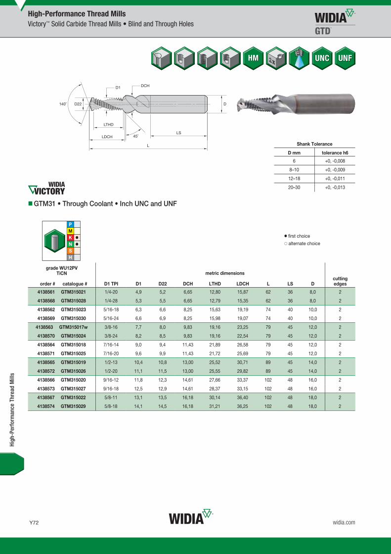
Y72
L V i WID M 16 T Y072 Y073 M i REBRAND O b 23 2015 9 55 AM
widia.com
WU12PV
High-Performance Thread MillsVictory™ Solid Carbide Thread Mills • Blind and Through Holes
Shank Tolerance
D mm tolerance h6
6 +0, -0,008
8–10 +0, -0,009
12–18 +0, -0,011
20–30 +0, -0,013
GTM31 • Through Coolant • Inch UNC and UNF
grade WU12PVTiCN
order # catalogue # D1 TPI D1 D22 DCH LTHD LDCH L LS Dcutting edges
4138561 GTM315021 1/4-20 4,9 5,2 6,65 12,80 15,87 62 36 8,0 2
4138568 GTM315028 1/4-28 5,3 5,5 6,65 12,79 15,35 62 36 8,0 2
4138562 GTM315023 5/16-18 6,3 6,6 8,25 15,63 19,19 74 40 10,0 2
4138569 GTM315030 5/16-24 6,6 6,9 8,25 15,98 19,07 74 40 10,0 2
4138563 GTM315017w 3/8-16 7,7 8,0 9,83 19,16 23,25 79 45 12,0 2
4138570 GTM315024 3/8-24 8,2 8,5 9,83 19,16 22,54 79 45 12,0 2
4138564 GTM315018 7/16-14 9,0 9,4 11,43 21,89 26,58 79 45 12,0 2
4138571 GTM315025 7/16-20 9,6 9,9 11,43 21,72 25,69 79 45 12,0 2
4138565 GTM315019 1/2-13 10,4 10,8 13,00 25,52 30,71 89 45 14,0 2
4138572 GTM315026 1/2-20 11,1 11,5 13,00 25,55 29,82 89 45 14,0 2
4138566 GTM315020 9/16-12 11,8 12,3 14,61 27,66 33,37 102 48 16,0 2
4138573 GTM315027 9/16-18 12,5 12,9 14,61 28,37 33,15 102 48 16,0 2
4138567 GTM315022 5/8-11 13,1 13,5 16,18 30,14 36,40 102 48 18,0 2
4138574 GTM315029 5/8-18 14,1 14,5 16,18 31,21 36,25 102 48 18,0 2
High
-Per
form
ance
Thr
ead
Mill
s
� first choice� alternate choice
metric dimensions
WID_Master16_Taps_Y072_Y073_Metric_REBRAND.indd 72 10/30/15 3:05 PM

Y73
L V i WID M 16 T Y072 Y073 M i REBRANDO b 23 20159 55AM
widia.com
WU12PV
High-Performance Thread MillsVictory™ Solid Carbide Thread Mills • Blind and Through Holes
GTM31 • Through Coolant • Metric and Metric Fine
grade WU12PVTiCN
order # catalogue # D1 size D1 D22 DCH LTHD LDCH L LS Dcutting edges
4138545 GTM315001 M4X0.7 3,2 3,3 4,30 7,74 9,59 49 36 6,0 2
4138546 GTM315002 M5X0.8 4,0 4,2 5,30 9,65 11,82 55 36 6,0 2
4138553 GTM315009 M6X0.75 5,1 5,3 6,30 12,07 14,37 62 36 8,0 2
4138547 GTM315003 M6X1 4,8 5,0 6,30 12,06 14,69 62 36 8,0 2
4138554 GTM315010 M8X1 6,8 7,0 8,30 16,09 19,10 74 40 10,0 2
4138548 GTM315004 M8X1.25 6,5 6,8 8,30 15,08 18,42 74 40 10,0 2
4138555 GTM315011 M10X1 8,7 9,0 10,30 20,11 23,52 79 45 12,0 2
4138556 GTM315012 M10X1.25 8,4 8,8 10,30 20,11 23,87 79 45 12,0 2
4138549 GTM315005 M10X1.5 8,2 8,5 10,30 19,59 23,65 79 45 12,0 2
4138557 GTM315013 M12X1.25 10,4 10,8 12,30 23,88 28,00 89 45 14,0 2
4138558 GTM315014 M12X1.5 10,2 10,5 12,30 24,12 28,57 89 45 14,0 2
4138550 GTM315006 M12X1.75 9,9 10,3 12,30 22,86 27,63 89 45 14,0 2
4138559 GTM315015 M14X1.5 12,1 12,5 14,30 27,14 31,98 102 48 16,0 2
4138551 GTM315007 M14X2 11,6 12,0 14,30 28,12 33,62 102 48 16,0 2
4138560 GTM315016 M16X1.5 14,1 14,5 16,30 31,65 36,87 102 48 18,0 2
4138552 GTM315008 M16X2 13,6 14,0 16,30 32,13 38,00 102 48 18,0 2
� first choice� alternate choice
metric dimensions
Shank Tolerance
D mm tolerance h6
6 +0, -0,008
8–10 +0, -0,009
12–18 +0, -0,011
20–30 +0, -0,013
High
-Per
form
ance
Thr
ead
Mill
s
WID_Master16_Taps_Y072_Y073_Metric_REBRAND.indd 73 10/30/15 3:05 PM
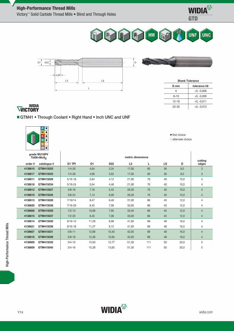
Y74
L V i WID M 16 T Y074 Y075 M i REBRAND O b 23 2015 9 55 AM
widia.com
WU16PV
High-Performance Thread MillsVictory™ Solid Carbide Thread Mills • Blind and Through Holes
Shank Tolerance
D mm tolerance h6
6 +0, -0,008
8–10 +0, -0,009
12–18 +0, -0,011
20–30 +0, -0,013
GTM41 • Through Coolant • Right Hand • Inch UNC and UNF
grade WU16PVTiAlN+MoS2
order # catalogue # D1 TPI D1 D22 L3 L LS Dcutting edges
4138610 GTM415025 1/4-20 4,64 3,34 17,00 60 36 8,0 3
4138617 GTM415033 1/4-28 4,66 3,62 17,00 60 36 8,0 3
4138611 GTM415026 5/16-18 5,64 4,12 21,90 76 40 10,0 4
4138618 GTM415034 5/16-24 5,64 4,48 21,90 76 40 10,0 4
4138612 GTM415027 3/8-16 7,16 5,42 26,30 76 40 10,0 4
4138619 GTM415035 3/8-24 7,14 6,00 26,30 76 40 10,0 4
4138613 GTM415028 7/16/14 8,47 6,49 31,00 86 45 12,0 4
4138620 GTM415036 7/16-20 8,45 7,06 33,00 86 45 12,0 4
4138606 GTM415029 1/2-13 10,08 7,95 33,40 86 45 12,0 4
4138615 GTM415037 1/2-20 8,45 7,06 33,00 86 45 12,0 4
4138614 GTM415030 9/16-12 11,28 8,98 41,00 98 48 16,0 4
4138621 GTM415038 9/16-18 11,27 9,72 41,00 98 48 16,0 4
4138607 GTM415031 5/8-11 12,89 10,40 42,00 98 48 16,0 4
4138616 GTM415039 5/8-18 12,38 10,83 42,00 98 48 16,0 4
4138608 GTM415032 3/4-10 15,50 12,77 51,30 111 50 20,0 5
4138609 GTM415040 3/4-16 15,38 13,65 51,30 111 50 20,0 5
High
-Per
form
ance
Thr
ead
Mill
s
� first choice� alternate choice
metric dimensions
WID_Master16_Taps_Y074_Y075_Metric_REBRAND.indd 74 10/30/15 3:05 PM

Y75
L V i WID M 16 T Y074 Y075 M i REBRANDO b 23 20159 55AM
widia.com
WU16PV
High-Performance Thread MillsVictory™ Solid Carbide Thread Mills • Blind and Through Holes
GTM41 • Through Coolant • Right Hand • Metric and Metric Fine
grade WU16PVTiAlN+MoS2
order # catalogue # D1 size D1 D22 L3 L LS Dcutting edges
4138576 GTM415001 M6X1 4,51 3,41 16,5 60 36 8,0 3
4138578 GTM415002 M7X1 4,51 3,41 16,5 60 36 8,0 3
4138592 GTM415014 M8X1 6,23 5,13 21,9 71 40 10,0 4
4138580 GTM415003 M8X1.25 6,23 4,91 21,9 71 40 10,0 4
4138593 GTM415015 M9X1 6,23 5,13 21,9 71 40 10,0 4
4138582 GTM415004 M9X1.25 6,23 4,91 21,9 71 40 10,0 4
4138594 GTM415016 M10X1 6,23 5,13 21,9 71 40 10,0 4
4138595 GTM415013 M10X1.25 6,23 4,91 21,9 71 40 10,0 4
4138584 GTM415005 M10X1.5 7,75 6,11 26,3 76 40 10,0 4
4138586 GTM415006 M11X1.5 7,75 6,11 26,3 76 40 10,0 4
4138596 GTM415017 M12X1 9,15 8,06 30,0 86 45 12,0 4
4138598 GTM415007 M12X1.5 7,75 6,11 26,3 76 40 10,0 4
4138587 GTM415008 M12X1.75 9,16 7,21 32,4 86 45 12,0 4
4138599 GTM415018 M14X1 9,15 8,06 30,0 86 45 12,0 4
4138600 GTM415019 M14X1.5 10,83 9,15 37,4 98 48 16,0 4
4138588 GTM415009 M14X2 11,08 8,91 41,0 98 48 16,0 4
4138601 GTM415020 M16X1.5 10,83 9,15 37,4 98 48 16,0 4
4138589 GTM415010 M16X2 11,08 8,91 41,0 98 48 16,0 4
4138602 GTM415021 M18X1.5 14,83 13,15 47,0 98 48 16,0 4
4138590 GTM415011 M18X2.5 14,38 11,71 51,3 111 50 20,0 5
4138603 GTM415022 M20X1.5 14,83 13,15 47,0 98 48 16,0 4
4138591 GTM415012 M20X2.5 14,38 11,71 51,3 111 50 20,0 5
4138604 GTM415023 M22X1.5 18,23 16,55 56,0 111 50 20,0 5
4138605 GTM415024 M24X1.5 18,23 16,55 56,0 111 50 20,0 5
� first choice� alternate choice
metric dimensions
Shank Tolerance
D mm tolerance h6
6 +0, -0,008
8–10 +0, -0,009
12–18 +0, -0,011
20–30 +0, -0,013
High
-Per
form
ance
Thr
ead
Mill
s
WID_Master16_Taps_Y074_Y075_Metric_REBRAND.indd 75 10/30/15 3:05 PM

Y76
L V i WID M 16 T Y076 Y077 M i REBRAND N b 11 2015 8 33 AM
widia.com
WU16PV
High-Performance Thread MillsVictory™ Solid Carbide Thread Mills • Blind and Through Holes
Shank Tolerance
D mm tolerance h6
6 +0, -0,008
8–10 +0, -0,009
12–18 +0, -0,011
20–30 +0, -0,013
GTM41 • Through Coolant • Left Hand • Metric and Metric Fine
grade WU16PVTiAlN+MoS2
order # catalogue # D1 size D1 D22 L3 L LS Dcutting edges
4138575 GTM415041 M6X1 4,51 3,41 16,5 60 36 8,0 3
4138577 GTM415042 M7X1 4,51 3,41 16,5 60 36 8,0 3
4138579 GTM415043 M8X1.25 6,23 4,91 21,9 71 40 10,0 4
4138581 GTM415044 M9X1.25 6,23 4,91 21,9 71 40 10,0 4
4138583 GTM415045 M10X1.5 7,75 6,11 26,3 76 40 10,0 4
4138585 GTM415046 M11X1.5 7,75 6,11 26,3 76 40 10,0 4
4138597 GTM415047 M12X1.5 9,17 7,21 32,4 86 45 12,0 4
High
-Per
form
ance
Thr
ead
Mill
s
� first choice� alternate choice
metric dimensions
WID_Master16_Taps_Y076_Y077_Metric_REBRAND.indd 76 11/11/15 8:59 AM

Y77
L V i WID M 16 T Y076 Y077 M i REBRANDN b 11 20158 33AM
widia.com
High
-Per
form
ance
Thr
ead
Mill
s
GTM11 and GTM21 • Metric
High-Performance Thread MillsApplication Data
Material Group
Thread Mill GTM11 Thread Mill • Chamfer GTM21
Cutting Speed — vc Feed/Toothby Diameter
Cutting Speed — vc Feed/Toothby DiameterRange — m/min Range — m/min
minStarting
Value max <10mm >10mm minStarting
Value max <10mm >10mm
P
1 90 115 150 mm 0,05 0,08 140 185 240 mm 0,06 0,10
2 90 115 150 mm 0,05 0,08 140 185 240 mm 0,06 0,10
3 40 50 70 mm 0,02 0,03 70 90 120 mm 0,03 0,04
4 – – – – – – 70 90 120 mm 0,03 0,04
5 60 80 100 mm 0,04 0,06 70 90 120 mm 0,05 0,08
6 – – – – – – – – – – – –
M
1 60 80 100 mm 0,04 0,06 70 90 120 mm 0,05 0,08
2 60 80 100 mm 0,04 0,06 70 90 120 mm 0,05 0,08
3 – – – – – – – – – – – –
K
1 120 150 200 mm 0,06 0,10 130 170 220 mm 0,06 0,11
2 120 150 200 mm 0,06 0,10 130 170 220 mm 0,06 0,11
3 90 115 150 mm 0,05 0,07 110 140 180 mm 0,05 0,07
N
1 200 225 250 mm 0,05 0,06 270 300 330 mm 0,08 0,16
2 170 190 210 mm 0,04 0,05 160 175 190 mm 0,08 0,16
3 250 275 300 mm 0,07 0,09 270 300 330 mm 0,08 0,16
4 250 275 300 mm 0,07 0,09 270 300 330 mm 0,08 0,16
5 270 300 330 mm 0,12 0,13 250 275 300 mm 0,11 0,20
6 170 190 210 mm 0,05 0,06 90 100 110 mm 0,11 0,20
S
1 60 80 100 mm 0,04 0,06 70 90 120 mm 0,05 0,08
2 50 65 80 mm 0,03 0,04 50 60 80 mm 0,03 0,05
3 50 65 80 mm 0,03 0,04 50 60 80 mm 0,03 0,05
4 50 65 80 mm 0,03 0,04 50 60 80 mm 0,03 0,05
Material Group
Drill • Chamfer • Thread Mill GTM31
Drilling Milling
Cutting Speed — vc Recommended Feedby Diameter
Feed/Toothby DiameterRange — m/min
minStarting
Value max <6mm 6–10mm 10–16mm <6mm 6–10mm 10–16mm
K 1 130 175 230 mm/r 0,10 0,16 0,30 mm 0,05 0,07 0,10
N
1 270 300 330 mm/r 0,15 0,25 0,34 mm 0,06 0,08 0,12
2 140 150 170 mm/r 0,15 0,25 0,34 mm 0,06 0,08 0,12
4 270 300 330 mm/r 0,15 0,25 0,34 mm 0,06 0,08 0,12
5 110 120 130 mm/r 0,12 0,20 0,32 mm 0,06 0,08 0,12
NOTE: For thread depths over 2 x D up to 3 x D, reduce speed and feed by 25%.
GTM31 • Metric
WID_Master16_Taps_Y076_Y077_Metric_REBRAND.indd 77 11/11/15 8:59 AM

Y78
L V i WID M 16 T Y078 Y079 M i REBRAND N b 10 2015 4 15 PM
widia.com
High-Performance Thread MillsApplication Data
High
-Per
form
ance
Thr
ead
Mill
s
Material Group
Mill • Chamfer • Thread Mill GTM41
Cutting Speed — vc Feed/Toothby DiameterRange — m/min
TM Style Grade minStarting
Value max < 10mm >10mm
P
1 GTM41 R WU16PV 170 225 290 mm 0,05 0,08
2 GTM41 R WU16PV 170 225 290 mm 0,05 0,08
3 GTM41 R WU16PV 120 150 200 mm 0,03 0,05
4 GTM41 R WU16PV 100 125 160 mm 0,03 0,05
5 GTM41 R WU16PV 120 150 200 mm 0,03 0,04
6 GTM41 R WU16PV 60 80 100 mm 0,03 0,04
M
1 GTM41 R WU16PV 120 150 200 mm 0,03 0,04
2 GTM41 R WU16PV 120 150 200 mm 0,03 0,04
3 GTM41 R WU16PV 120 150 200 mm 0,03 0,04
K
1 GTM41 R WU16PV 190 250 330 mm 0,06 0,10
2 GTM41 R WU16PV 190 250 330 mm 0,06 0,10
3 GTM41 R WU16PV 140 185 240 mm 0,04 0,07
N
1 – – – – – – – –
2 GTM41 R WU16PV 180 230 300 mm 0,06 0,07
3 – – – – – – – –
4 GTM41 R WU16PV 210 275 360 mm 0,06 0,07
5 – – – – – – – –
6 GTM41 R WU16PV 210 275 360 mm 0,06 0,07
S
1 GTM41 L WU16PV 120 150 200 mm 0,025 0,045
2 GTM41 L WU16PV 50 60 80 mm 0,015 0,025
3 GTM41 L WU16PV 50 60 80 mm 0,015 0,025
4 GTM41 L WU16PV 70 90 120 mm 0,025 0,035
H
1 GTM41 WU16PV 80 100 130 mm 0,030 0,050
2 GTM41 WU16PV 80 100 130 mm 0,030 0,050
3 GTM41 WU16PV 50 65 80 mm 0,020 0,030
4 GTM41 WU16PV 50 65 80 mm 0,020 0,030
NOTE: For thread depths over 2 x D up to 3 x D, reduce speed and feed by 25%.
Universal Thread Mills • GTM41 • Metric
WID_Master16_Taps_Y078_Y079_Metric_REBRAND.indd 78 11/10/15 5:04 PM

Y79
L V i WID M 16 T Y078 Y079 M i REBRANDN b 10 20154 15PM
widia.com
Thread Milling Methods
Climb Milling
High-Performance Thread MillsCNC Programming Instructions
Conventional Milling
Counter Feed Fk Centre Point Feed Fm
Fk = n • fz • Z [mm/min]
Counter Feed (Fk)
Centre Point Feed (Fm)
Dw = Tool diameter [mm]
n = RPM [min-1]
fz = Feed per tooth [mm]
Z = Number of teeth on tool (radial)
D = Nominal diameter of thread = Diameter of external contour [mm]
Dm = Diameter of the centre point (D-Dw) [mm]
High
-Per
form
ance
Thr
ead
Mill
s
B
h = max
B
A
Properties:
Tool rotation direction clockwise
Tool moves clockwise
Pitch downwards
Right-hand thread
Conventional milling is always when thecutting edge goes out of the material witha chip thickness h = max
Properties:
Tool rotation direction clockwise
Tool moves anti-clockwise
Pitch upwards
Right-hand thread
Climb milling is always when the cuttingedge goes out of the material with a chipthickness h = 0
Fm = [mm/min]Fk • (D-Dw)
D
WID_Master16_Taps_Y078_Y079_Metric_REBRAND.indd 79 11/10/15 5:04 PM

Y80
L V i WID M 16 T Y080 Y081 M i REBRAND N b 13 2015 9 16 AM
widia.com
Thread Mill GTM21
High-Performance Thread MillsCNC Programming Instructions
High
-Per
form
ance
Thr
ead
Mill
s Positioning the tool N 10 G 54 G 90 G 00 X… Y… Z 2 S 9709 T01 2 M03
Advancing tool to full thread depth N 20 G 91 Z-21.200
Countersinking N 30 G 01 Z-2 F 2913 (countersink)
Raise N 40 G 00 Z 3.450
Moving sideways to the starting point N 50 G 42 G01 X 4.250 F 1311 (milling, 1/2 contour) [F 236] 3 (milling,1/2 centre point)
Run-in loop in arc N 60 G 02 X-9.25 Y 0.000 Z-0.750 I-4.625 J 0
Thread milling N 70 G 02 X 0 Y 0 Z-1.500 I 5 J 0.000 F2622 [F 472] 3 (centre point)
Run-out loop in arc N 80 G 02 X 9.25 Y 0.000 Z-0.750 I 4.625 J 0
Exit N 90 G 40 G 01 X-4.25
Retracting tool to positioning level N 100 G 90 G 00 Z 2
Preparation Drilling of thread hole
Process Principle Countersinking, thread milling (conventional milling)
Cycle
Required Specification Values
Example
Size — M10-6HThread diameter D .........................................10mmPitch .............................................................1,5mmCore hole diameter D1 ..................................8,5mm
Material — Cast aluminiumGrade — WU12PV
Tool — GTM21Catalogue number ................................................GTM215004Number of teeth Z ..................................................................3Tool diameter d1 ..........................................................8,2mm*Tool radius compensation k1 ..................................... 0,1mm**Tool radius to be programmed2 ...................................4mm***Countersink depth ls ...................................................21,2mmCutting speed vc ..................................................... 250 m/minFeed (countersinking) fs ............................................0,3 mm/UFeed (milling) fz ................................................ 0,09 mm/tooth
*(measured on the cutting part) **(0.01 x D) ***(1/2 d1 - k)
Program to DIN 66025 (conventional milling, on the contour, incremental)
1.4 seconds
NOTES:1 The cutter radius measured over the tooth crests of the threaded part must be reduced by the amount of the cutter radius compensation. This is necessary to achieve a depth of cut to the middle
of the 6H/ISO2 nut tolerance. Please note, however, that this also depends on the radial deflection of the tool (tensile strength of the material, projecting length of the tool).2 The cutter radius to be programmed is normally included in the tool memory.3 The feed values in brackets must be used for controllers, which do not calculate the centre point feed themselves.
Cutting time th
Positioning Countersinking Raise Run-in loop forthread milling
Thread milling Run-out loop Returning topositioning level
N =Vc • 1000
S = 9709d1 •
vs = fs • n F =2913(countersinking)
vf = fz • Z • n F =2622(contour)
vf =vf contour • (D-d1)
F =472(centre point)D
WID_Master16_Taps_Y080_Y081_Metric_REBRAND.indd 80 11/13/15 9:40 AM
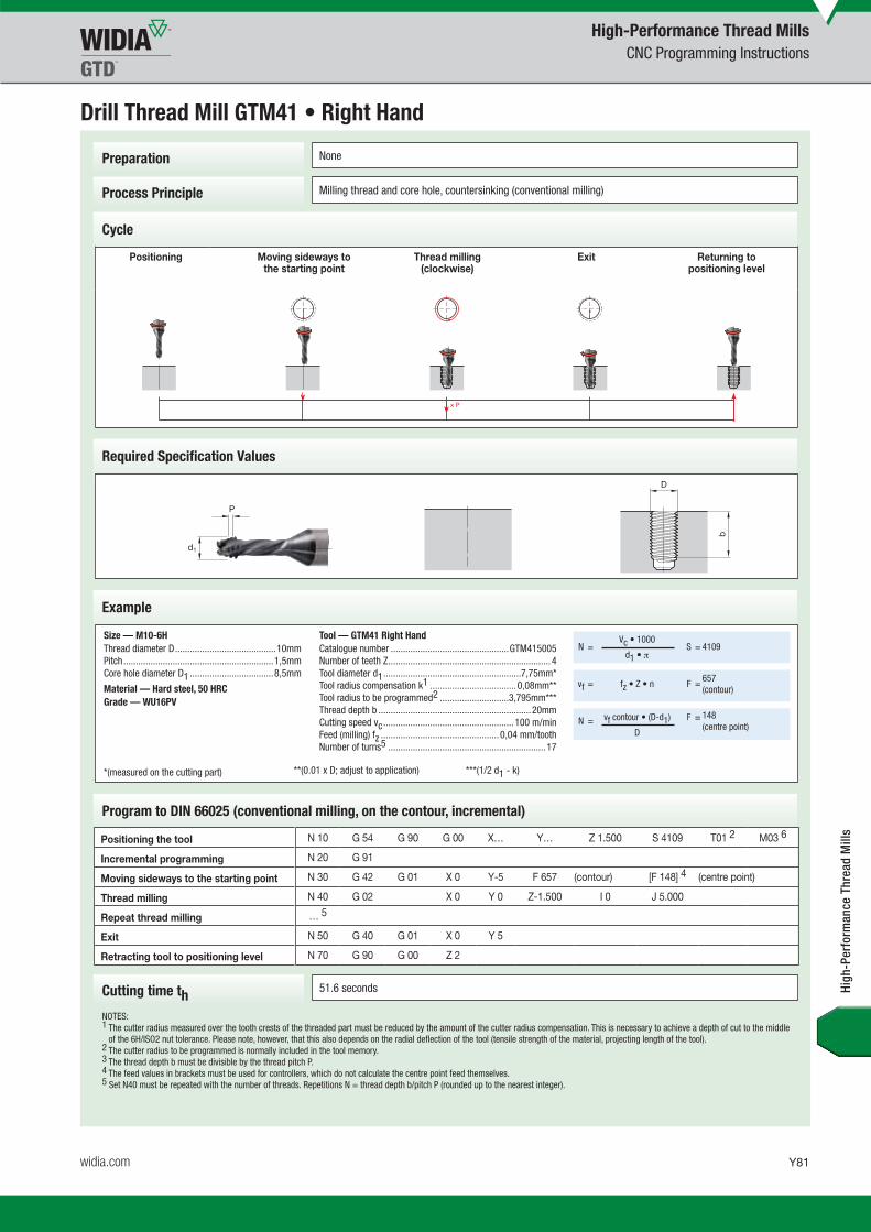
Y81
L V i WID M 16 T Y080 Y081 M i REBRANDN b 13 20159 16AM
widia.com
Drill Thread Mill GTM41 • Right Hand
Preparation None
Process Principle Milling thread and core hole, countersinking (conventional milling)
Cycle
Required Specification Values
Example
Size — M10-6HThread diameter D .........................................10mmPitch .............................................................1,5mmCore hole diameter D1 ..................................8,5mm
Material — Hard steel, 50 HRCGrade — WU16PV
Tool — GTM41 Right HandCatalogue number ................................................GTM415005Number of teeth Z ..................................................................4Tool diameter d1 ........................................................7,75mm*Tool radius compensation k1 ................................... 0,08mm**Tool radius to be programmed2 ............................3,795mm***Thread depth b ..............................................................20mmCutting speed vc ..................................................... 100 m/minFeed (milling) fz ................................................ 0,04 mm/toothNumber of turns5 ................................................................17
*(measured on the cutting part) **(0.01 x D; adjust to application) ***(1/2 d1 - k)
Program to DIN 66025 (conventional milling, on the contour, incremental)
51.6 seconds
NOTES:1 The cutter radius measured over the tooth crests of the threaded part must be reduced by the amount of the cutter radius compensation. This is necessary to achieve a depth of cut to the middle
of the 6H/ISO2 nut tolerance. Please note, however, that this also depends on the radial deflection of the tool (tensile strength of the material, projecting length of the tool).2 The cutter radius to be programmed is normally included in the tool memory.3 The thread depth b must be divisible by the thread pitch P.4 The feed values in brackets must be used for controllers, which do not calculate the centre point feed themselves.5 Set N40 must be repeated with the number of threads. Repetitions N = thread depth b/pitch P (rounded up to the nearest integer).
Cutting time th
High-Performance Thread MillsCNC Programming Instructions
Positioning Moving sideways to the starting point
Thread milling(clockwise)
Exit Returning topositioning level
N =Vc • 1000
S = 4109d1 •
vf = fz • Z • n F =657(contour)
N = vf contour • (D-d1) F = 148(centre point)
D
High
-Per
form
ance
Thr
ead
Mill
sPositioning the tool N 10 G 54 G 90 G 00 X… Y… Z 1.500 S 4109 T01 2 M03 6
Incremental programming N 20 G 91
Moving sideways to the starting point N 30 G 42 G 01 X 0 Y-5 F 657 (contour) [F 148] 4 (centre point)
Thread milling N 40 G 02 X 0 Y 0 Z-1.500 I 0 J 5.000
Repeat thread milling … 5
Exit N 50 G 40 G 01 X 0 Y 5
Retracting tool to positioning level N 70 G 90 G 00 Z 2
WID_Master16_Taps_Y080_Y081_Metric_REBRAND.indd 81 11/13/15 9:40 AM

Y82
L V i WID M 16 T Y082 Y083 M i REBRAND N b 13 2015 9 18 AM
widia.com
Drill Thread Mill GTM41 • Left Hand
Preparation None
Process Principle Milling thread and core hole, countersinking (climb milling)
Cycle
Required Specification Values
Example
Size — M10-6HThread diameter D .........................................10mmPitch .............................................................1,5mmCore hole diameter D1 ..................................8,5mm
Material — TiAl6V4 titaniumGrade — WU16PV
Tool — GTM41 Left HandCatalogue number ................................................GTM415005Number of teeth Z ..................................................................4Tool diameter d1 ........................................................7,75mm*Tool radius compensation k1 ................................... 0,08mm**Tool radius to be programmed2 ............................3,795mm***Thread depth b ..............................................................20mmCutting speed vc ..................................................... 100 m/minFeed (milling) fz ................................................ 0,03 mm/toothNumber of turns5 ................................................................17
*(measured on the cutting part) **(0.01 x D) ***(1/2 d1 - k)
Program to DIN 66025 (climb milling, on the contour, incremental)
68.8 seconds
NOTES:1 The cutter radius measured over the tooth crests of the threaded part must be reduced by the amount of the cutter radius compensation. This is necessary to achieve a depth of cut to the middle
of the 6H/ISO2 nut tolerance. Please note, however, that this also depends on the radial deflection of the tool (tensile strength of the material, projecting length of the tool).2 The cutter radius to be programmed is normally included in the tool memory.3 The thread depth b must be divisible by the thread pitch P.4 The feed values in brackets must be used for controllers, which do not calculate the centre point feed themselves.5 Set N40 must be repeated with the number of threads. Repetitions N = thread depth b/pitch P (rounded up to the nearest integer).
Cutting time th
High-Performance Thread MillsCNC Programming Instructions
Positioning Moving sideways to the starting point
Thread milling(anti-clockwise) Exit Returning to
positioning level
Positioning the tool N 10 G 54 G 90 G 00 X… Y… Z 1.500 S 4109 T01 2 M04
Incremental programming N 20 G 91
Moving sideways to the starting point N 30 G 42 G 01 X 0 Y-5 F 493 (contour) [F 111] 4 (centre point)
Thread milling N 40 G 02 X 0 Y 0 Z-1.500 I 0 J 5.000
Repeat thread milling … 5
Exit N 50 G 40 G 01 X 0 Y 5
Retracting tool to positioning level N 70 G 90 G 00 Z 2
N =Vc • 1000
S = 4109d1 •
vf = fz • Z • n F =493(contour)
N =vf contour • (D-d1) F = 111
(centre point)D
High
-Per
form
ance
Thr
ead
Mill
s
WID_Master16_Taps_Y082_Y083_Metric_REBRAND.indd 82 11/13/15 9:40 AM

Y83
L V i WID M 16 T Y082 Y083 M i REBRANDN b 13 20159 18AM
widia.com
Drill Thread Mill GTM31
Preparation Drilling of thread hole
Process Principle Drilling, countersinking, thread milling (climb milling)
Cycle
Required Specification Values
Example
Size — M10-6HThread diameter D .........................................10mmPitch .............................................................1,5mmCore hole diameter D1 ..................................8,5mm
Material — Grey cast ironGrade — WU12PV
Tool — GTM31Catalogue number ................................................GTM315005Number of teeth Z ..................................................................2Tool diameter d1 ..........................................................8,2mm*Tool radius compensation k1 ..................................... 0,1mm**Tool radius to be programmed2 ...................................4mm***Countersink depth ls .................................................19,11mmCutting speed vc ..................................................... 250 m/minFeed (countersinking) fs ..........................................0,25 mm/UFeed (milling) fz .................................................. 0,1 mm/tooth
*(measured on the cutting part) **(0.01 x D) ***(1/2 d1 - k)
Program to DIN 66025 (climb milling, on the contour, incremental)
2.3 seconds
NOTES:1 The cutter radius measured over the tooth crests of the threaded part must be reduced by the amount of the cutter radius compensation. This is necessary to achieve a depth of cut to the middle
of the 6H/ISO2 nut tolerance. Please note, however, that this also depends on the radial deflection of the tool (tensile strength of the material, projecting length of the tool).2 The cutter radius to be programmed is normally included in the tool memory.3 The feed values in brackets must be used for controllers, which do not calculate the centre point feed themselves.
Cutting time th
Positioning the tool N 10 G 54 G 90 G 00 X… Y… Z 2 S 9709 T01 2 M03
Drilling and countersinking N 20 G 91 G 01 Z-21.110 F 2427 (drill, countersink)
Raise N 30 G 01 Z 0.500
Moving sideways to the starting point N 40 G 41 Y-4.250 F 971 (milling, 1/2 contour) [F 175] 3 (1/2 centre point)
Run-in loop in arc N 50 G 03 X 0 Y 9.250 Z 0.750 I 0 J 4.625
Thread milling N 60 G 03 X 0 Y 0 Z 1.500 I 0 J -5.000
Run-out loop in arc N 70 G 03 X 0 Y-9.250 Z 0.750 I 0 J- 4.625 F1942 [F 350] 3 (centre point)
Exit N 80 G 00 G 40 X 0 Y 4.250
Retracting tool to positioning level N 90 G 90 Z 2
Positioning Drilling andcountersinking Raise Run-in loop for
thread milling Thread milling Run-out loop Returning topositioning level
High-Performance Thread MillsCNC Programming Instructions
N =Vc • 1000
S = 9709d1 •
vs = fb • n F =2427 (drilling,countersinking)
vf = fz • Z • n F =1942(contour)
vf =vf contour • (D-d1) F = 350
(centre point)D
High
-Per
form
ance
Thr
ead
Mill
s
WID_Master16_Taps_Y082_Y083_Metric_REBRAND.indd 83 11/13/15 9:40 AM

Y84
L V i WID M 16 T Y084 Y085 M i REBRAND N b 13 2015 9 19 AM
widia.com
High-Performance TapsApplication Data
High
-Per
form
ance
Tap
s
Carbide Taps • Metric
Through Holes Blind Holes
Range — m/min Range — m/min
Material Group Tap Style Grade min
StartingValue max Tap Style Grade min
StartingValue max
P
P0 GX32, GX38 GP4535 60 100 130 GX33, GX39 GP4535 50 70 90
P1 GX32, GX38 GP4535 60 90 120 GX33, GX39 GP4535 40 60 80
P2 GX32, GX38 GP4535 50 85 110 GX33, GX39 GP4535 40 60 80
P3 GX32, GX38 GP4535 50 80 100 GX33, GX39 GP4535 40 60 80
K
K1 GX34, GX50 WK12PG 70 105 140 GX35, GX50 WK12PG 50 70 90
K2 GX34, GX50 WK12PG 60 100 130 GX35, GX50 WK12PG 50 70 90
K3 GX34, GX50 WK12PG 60 90 120 GX35, GX50 WK12PG 40 60 80
N
N2 GX46, GX48 WN14PG 80 120 160 GX47, GX49 WN14PG 60 80 100
N3 GX46, GX48 WN14PG 60 100 130 GX47, GX49 WN14PG 50 70 90
N4 GX46, GX48 WN14PG 60 90 120 GX47, GX49 WN14PG 40 60 80
HH3 GX10 WH16PG 1,2 1,5 2,0 GX10 WH16PG 0,8 1,1 1,4
H4 GX10 WH16PG 0,6 0,8 1,0 GX10 WH16PG 0,4 0,5 0,7
WID_Master16_Taps_Y084_Y085_Metric_REBRAND.indd 84 11/13/15 9:40 AM
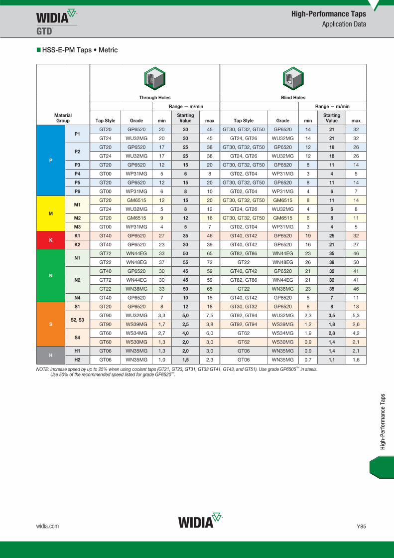
Y85
L V i WID M 16 T Y084 Y085 M i REBRANDN b 13 20159 19AM
widia.com
High-Performance TapsApplication Data
High
-Per
form
ance
Tap
s
HSS-E-PM Taps • Metric
Through Holes Blind Holes
Range — m/min Range — m/min
Material Group Tap Style Grade min
StartingValue max Tap Style Grade min
StartingValue max
P
P1GT20 GP6520 20 30 45 GT30, GT32, GT50 GP6520 14 21 32
GT24 WU32MG 20 30 45 GT24, GT26 WU32MG 14 21 32
P2GT20 GP6520 17 25 38 GT30, GT32, GT50 GP6520 12 18 26
GT24 WU32MG 17 25 38 GT24, GT26 WU32MG 12 18 26
P3 GT20 GP6520 12 15 20 GT30, GT32, GT50 GP6520 8 11 14
P4 GT00 WP31MG 5 6 8 GT02, GT04 WP31MG 3 4 5
P5 GT20 GP6520 12 15 20 GT30, GT32, GT50 GP6520 8 11 14
P6 GT00 WP31MG 6 8 10 GT02, GT04 WP31MG 4 6 7
M
M1GT20 GM6515 12 15 20 GT30, GT32, GT50 GM6515 8 11 14
GT24 WU32MG 5 8 12 GT24, GT26 WU32MG 4 6 8
M2 GT20 GM6515 9 12 16 GT30, GT32, GT50 GM6515 6 8 11
M3 GT00 WP31MG 4 5 7 GT02, GT04 WP31MG 3 4 5
KK1 GT40 GP6520 27 35 46 GT40, GT42 GP6520 19 25 32
K2 GT40 GP6520 23 30 39 GT40, GT42 GP6520 16 21 27
N
N1GT72 WN44EG 33 50 65 GT82, GT86 WN44EG 23 35 46
GT22 WN48EG 37 55 72 GT22 WN48EG 26 39 50
N2
GT40 GP6520 30 45 59 GT40, GT42 GP6520 21 32 41
GT72 WN44EG 30 45 59 GT82, GT86 WN44EG 21 32 41
GT22 WN38MG 33 50 65 GT22 WN38MG 23 35 46
N4 GT40 GP6520 7 10 15 GT40, GT42 GP6520 5 7 11
S
S1 GT20 GP6520 8 12 18 GT30, GT32 GP6520 6 8 13
S2, S3GT90 WU32MG 3,3 5,0 7,5 GT92, GT94 WU32MG 2,3 3,5 5,3
GT90 WS39MG 1,7 2,5 3,8 GT92, GT94 WS39MG 1,2 1,8 2,6
S4GT60 WS34MG 2,7 4,0 6,0 GT62 WS34MG 1,9 2,8 4,2
GT60 WS30MG 1,3 2,0 3,0 GT62 WS30MG 0,9 1,4 2,1
HH1 GT06 WN35MG 1,3 2,0 3,0 GT06 WN35MG 0,9 1,4 2,1
H2 GT06 WN35MG 1,0 1,5 2,3 GT06 WN35MG 0,7 1,1 1,6
NOTE: Increase speed by up to 25% when using coolant taps (GT21, GT23, GT31, GT33 GT41, GT43, and GT51). Use grade GP6505™ in steels. Use 50% of the recommended speed listed for grade GP6520™.
WID_Master16_Taps_Y084_Y085_Metric_REBRAND.indd 85 11/13/15 9:40 AM

Y86
L V i WID M 16 T Y086 Y087 M i REBRAND N b 13 2015 9 20 AM
widia.com
High-Performance TapsApplication Data • VariTap™
High
-Per
form
ance
Tap
s
VariTap • HSS-E • Metric
Through Holes Blind Holes
Range — m/min Range — m/min
Material Group Tap Style Grade min
StartingValue max Tap Style Grade min
StartingValue max
P
P1VT-SPO WP42EG, WU41EG 21 27 34 VT-SFT WP42EG, WU41EG 13 18 26
VT-SPO WP49EG, WU40EG 10 14 17 VT-SFT WP49EG, WU40EG 6 9 13
P2VT-SPO WP42EG, WU41EG 16 21 27 VT-SFT WP42EG, WU41EG 11 15 22
VT-SPO WP49EG, WU40EG 8 11 13 VT-SFT WP49EG, WU40EG 4 6 9
P3
VT-SPO WP42EG, WU41EG 9 12 15 VT-SFT WP42EG, WU41EG 6 9 13
VT-SPO WP49EG, WU40EG 5 6 8 VT-SFT WP49EG, WU40EG 2 3 4
VT-STR NPT WU41EG 5 6 8 VT-STR NPT WU41EG 5 6 8
VT-STR NPT WU40EG 2 3 4 VT-STR NPT WU40EG 2 3 4
M
M1
VT-SPO WP42EG, WU41EG 9 12 15 VT-SFT WP42EG, WU41EG 6 9 13
VT-SPO WP49EG, WU40EG 5 6 8 VT-SFT WP49EG, WU40EG 2 3 4
VT-SFT NPT WU41EG 5 6 8 VT-SFT NPT WU41EG 5 6 8
VT-SFT NPT WP49EG, WU40EG 2 3 4 VT-SFT NPT WP49EG, WU40EG 2 3 4
M3VT-SPO WP42EG, WU41EG 7 9 11 VT-SFT WP42EG, WU41EG 4 6 9
VT-SPO WP49EG, WU40EG 3 5 6 VT-SFT WP49EG, WU40EG 2 3 4
K
K1VT-STR NPT WU41EG 10 14 17 VT-STR NPT WU41EG 10 14 17
VT-STR NPT WU40EG 6 8 10 VT-STR NPT WU40EG 6 8 10
K2VT-SPO WP42EG, WU41EG 21 27 34 VT-SFT WP42EG, WU41EG 13 18 26
VT-SPO WP49EG, WU40EG 10 14 17 VT-SFT WP49EG, WU40EG 6 9 13
N
N1VT-SPO WP42EG, WU41EG 34 46 57 VT-SFT WP42EG, WU41EG 23 34 48
VT-SPO WU40EG 17 23 29 VT-SFT WU40EG 11 15 22
N2VT-SPO WP42EG, WU41EG 30 40 50 VT-SFT WP42EG, WU41EG 19 27 39
VT-SPO WU40EG 15 20 25 VT-SFT WU40EG 11 15 22
N4VT-SPO WP42EG, WU41EG 7 9 11 VT-SFT WP42EG, WU41EG 4 6 9
VT-SPO WU40EG 3 5 6 VT-SFT WU40EG 2 3 4
* Grades: WP42EG = TiCN WU41EG = TiN WP49EG = oxide WU40EG = bright
WID_Master16_Taps_Y086_Y087_Metric_REBRAND.indd 86 11/13/15 9:40 AM

L V i WID M 16 T Y086 Y087 M i REBRANDN b 13 20159 20AM
Global Reconditioning Network
To use WIDIA tool reconditioning services, contact your authorised WIDIA distributor to get started.
Reconditioning Services
Anyone can regrind our tools – but only we can recondition them
WIDIA™ Reconditioning Services optimise the value of metalcutting tools throughout their entire lifecycle by giving like-new performance — with rapid turnaround time — so tools are always on hand and perform just like new.
Huntley, IL
Kingwinford, UK
Istanbul, Turkey
Shlomi, Israel
Tianjin, China
Shanghai, China
Busan, Korea
Bangalore, India
Zory, Poland
Gurgaon, India
Pune, India
Koenigsee, Germany
Barcelona, Spain Milan, Italy
Indaiatuba, Brazil
Whitehouse, OH
Asheboro, NC
To locate a Reconditioning Center near you, visit widia.com/services.
WID_Master16_Taps_Y086_Y087_Metric_REBRAND.indd 87 11/13/15 9:40 AM

Y88
L V i WID M 16 T Y088 Y089 M i REBRAND N b 10 2015 4 29 PM
widia.com
Technical InformationIllustrations of Tap Terms
max tap major diameter
basic major diameter
basic pitch diameter
base of thread
basic root
tap crest
basic crest
flank
basic height of thread
basic minor diameter
angle of thread
min tap major
diameter
pitch
cutting face
cutting edge relief to cutting edge
concentric margin
eccentric relief
Concentric Eccentric Relief Con-Eccentric Relief
tap major diameter
basic minor diameter
Negative Hook 0º Hook Positive Hook
Negative Rake Radial Rake Positive Rake
no relief
heel
Reprinted with permission from United States Cutting Tool Institute (USCTI). Published by Kennametal Inc. © 2014. All rights reserved.
Tech
nica
l Inf
orm
atio
n
WID_Master16_Taps_Y088_Y089_Metric_REBRAND.indd 88 11/10/15 5:04 PM

Y89
L V i WID M 16 T Y088 Y089 M i REBRANDN b 10 20154 29PM
widia.com
Technical InformationTap Chamfers
Tap Chamfers • ANSI Taps
Taper Chamfer 7–10 Pitches
Taper (7–10 pitches)
The taper chamfer has the longest standard chamfer ensuring easier starting. It requires less tapping torque because of more working teeth.
Plug Chamfer 3–5 Pitches
Plug (3–5 pitches)
The most common chamfer for use by hand or machine in through or blind holes. This chamfer is more efficient than a bottoming or modified bottoming chamfer.
Modified Bottoming Chamfer 2–2.5 Pitches
Full Bottoming Chamfer 1–2 Pitches
Semi-Bottom (2–2.5 pitches)
This short chamfer enables threading close to the bottom of blind holes. Due to the slightly longer chamfer and more working teeth, this chamfer is more efficient than a bottoming chamfer.
Tap Chamfers
Bottoming (1–2 pitches)
For threading close to the bottom of blind holes, the bottoming chamfer is the least efficient chamfer available.
Taper Chamfer 7–10 Pitches
Plug Chamfer 3–5 Pitches
Modified Bottoming Chamfer 2–2.5 Pitches
Full Bottoming Chamfer 1–2 Pitches
Tap Chamfers • DIN Taps
Form A (6–8 pitches)
The Form A chamfer has the longest standard chamfer ensuring easier starting. It requires less tapping torque because of more working teeth.
Form B/D (3.5–5 pitches)
The most common chamfers for use by hand or machine in through or blind holes. Form B applies to spiral-point taps and Form D applies to straight-flute and spiral-flute taps. This chamfer is more efficient than Form E or Form C chamfer.
Form C (2–2.5 pitches)
This short chamfer enables threading close to the bottom of blind holes. Due to the slightly longer chamfer and more working teeth, this chamfer is more efficient than a Form E chamfer.
Form E (1.5–2 pitches)
For threading close to the bottom of blind holes, the Form E chamfer is the least efficient chamfer available.
Hand Tap Chamfers
Tech
nica
l Inf
orm
atio
n
WID_Master16_Taps_Y088_Y089_Metric_REBRAND.indd 89 11/10/15 5:04 PM

Y90
L V i WID M 16 T Y090 Y091 M i REBRAND N b 10 2015 2 06 PM
widia.com
Technical InformationStandard Tap Dimensions • Ground Thread • Reference USCTI Table 302
nominal diameter
range (in)
machine screw size
number (in)
nominal fractional diameter
(in)
nominal metric
diameter mm (in)
blank design
number
overall length
L
thread length
l
square length
l2
shank diameter
D1
square size
A
.052–.065 0 (.0600) — M1.6 (.0630) 1 1.63 .31 .19 .1410 .110
.065–.078 1 (.0730) — M1.8 (.0709) 1 1.69 .38 .19 .1410 .110
.078–.091 2 (.0860) — M2 (0787), M2.2 (.0866) 1 1.75 .44 .19 .1410 .110
.091–.104 3 (.0990) — M2.5 (.0984) 1 1.81 .50 .19 .1410 .110
.104–.117 4 (.1120) — — — 1 1.88 .56 .19 .1410 .110
.117–.130 5 (.1250) — M3 (.1181) 1 1.94 .63 .19 .1410 .110
.130–.145 6 (.1380) — M3.5 (.1378) 1 2.00 .69 .19 .1410 .110
.145–.171 8 (.1640) — M4 (.1575) 1 2.13 .75 .25 .1680 .131
.171–.197 10 (.1900) — M4.5 (.1772), M5 (.1969) 1 2.38 .88 .25 .1940 .152
.197–.223 12 (.2160) — — — 1 2.38 .94 .28 .2200 .165
.223–.260 — 1/4 (.2500) M6 (.2362) 2 2.50 1.00 .31 .2550 .191
.260–.323 — 5/16 (.3125) M7 (.2756), M8 (.3150) 2 2.72 1.13 .38 .3180 .238
.323–.395 — 3/8 (.3750) M10 (.3937) 2 2.94 1.25 .44 .3810 .286
.395–.448 — 7/16 (.4375) — — 3 3.16 1.44 .41 .3230 .242
.448–.510 — 1/2 (.5000) M12 (.4724) 3 3.38 1.66 .44 .3670 .275
.510–.573 — 9/16 (.5625) M14 (.5512) 3 3.59 1.66 .50 .4290 .322
.573–.635 — 5/8 (.6250) M16 (.6299) 3 3.81 1.81 .56 .4800 .360
.635–.709 — 11/16 (.6875) M18 (.7087) 3 4.03 1.81 .63 .5420 .406
.709–.760 — 3/4 (.7500) — — 3 4.25 2.00 .69 .5900 .442
.760–.823 — 13/16 (.8125) M20 (.7874) 3 4.47 2.00 .69 .6520 .489
.823–.885 — 7/8 (.8750) M22 (.8661) 3 4.69 2.22 .75 .6970 .523
.885–.948 — 15/16 (.9375) M24 (.9449) 3 4.91 2.22 .75 .7600 .570
.948–1.010 — 1 (1.0000) M25 (.9843) 3 5.13 2.50 .81 .8000 .600
1.010–1.073 — 1-1/16 (1.0625) M27 (1.0630) 3 5.13 2.50 .88 .8960 .672
1.073–1.135 — 1-1/8 (1.1250) — — 3 5.44 2.56 .88 .8960 .672
1.135–1.198 — 1-3/16 (1.1875) M30 (1.1811) 3 5.44 2.56 1.00 1.0210 .766
1.198–1.260 — 1-1/4 (1.2500) — — 3 5.75 2.56 1.00 1.0210 .766
1.260–1.323 — 1-5/16 (1.3125) M33 (1.2992) 3 5.75 2.56 1.06 1.1080 .831
1.323–1.385 — 1-3/8 (1.3750) — — 3 6.06 3.00 1.06 1.1080 .831
1.358–1.448 — 1-7/16 (1.4375) M36 (1.4173) 3 6.06 3.00 1.13 1.2330 .925
1.448–1.510 — 1-1/2 (1.5000) — — 3 6.38 3.00 1.13 1.2330 .925
1.510–1.635 — 1-5/8 (1.6250) M39 (1.5354) 3 6.69 3.19 1.13 1.3050 .979
1.635–1.760 — 1-3/4 (1.7500) M42 (1.6535) 3 7.00 3.19 1.25 1.4300 1.072
1.760–1.885 — 1-7/8 (1.8750) — — 3 7.31 3.56 1.25 1.5190 1.139
1.885–2.010 — 2 (2.0000) M48 (1.8898) 3 7.63 3.56 1.38 1.6440 1.233
2.010–2.135 — 2-1/8 (2.1250) — — 3 8.00 3.56 1.38 1.7690 1.327
2.135–2.260 — 2-1/4 (2.2500) M56 (2.2047) 3 8.25 3.56 1.44 1.8940 1.420
2.260–2.385 — 2-3/8 (2.3750) — — 3 8.50 4.00 1.44 2.0190 1.514
2.385–2.510 — 2-1/2 (2.5000) — — 3 8.75 4.00 1.50 2.1000 1.575
2.510–2.635 — 2-5/8 (2.6250) M64 (2.5197) 3 8.75 4.00 1.50 2.2250 1.669
2.635–2.760 — 2-3/4 (2.7500) — — 3 9.25 4.00 1.56 2.3500 1.762
2.760–2.885 — 2-7/8 (2.8750) M72 (2.8346) 3 9.25 4.00 1.56 2.4750 1.856
2.885–3.010 — 3 (3.0000) — — 3 9.75 4.56 1.63 2.5430 1.907
3.010–3.135 — 3-1/8 (3.1250) — — 3 9.75 4.56 1.63 2.6680 2.001
3.135–3.260 — 3-1/4 (3.2500) M80 (3.1496) 3 10.00 4.56 1.75 2.7930 2.095
3.260–3.385 — 3-3/8 (3.3750) — — 3 10.00 4.56 1.75 2.8830 2.162
3.385–3.510 — 3-1/2 (3.5000) — — 3 10.25 4.94 2.00 3.0080 2.256
3.510–3.635 — 3-5/8 (3.6250) M90 (3.5433) 3 10.25 4.94 2.00 3.1330 2.350
3.635–3.760 — 3-3/4 (3.7500) — — 3 10.50 5.31 2.13 3.2170 2.413
3.760–3.885 — 3-7/8 (3.8750) — — 3 10.50 5.31 2.13 3.3420 2.506
3.885–4.010 — 4 (4.0000) M100 (3.9370) 3 10.75 5.31 2.25 3.4670 2.600
Blank Design 1 Blank Design 2 Blank Design 3
Reprinted with permission from United States Cutting Tool Institute (USCTI). Published by Kennametal Inc. © 2014. All rights reserved.
Tech
nica
l Inf
orm
atio
n
WID_Master16_Taps_Y090_Y091_Metric_REBRAND.indd 90 11/10/15 2:22 PM

Y91
L V i WID M 16 T Y090 Y091 M i REBRANDN b 10 20152 06PM
widia.com
Technical InformationOptional Neck and Shortened Thread Length Dimensions • Reference USCTI Table 302A
Special Taps
Reprinted with permission from United States Cutting Tool Institute (USCTI). Published by Kennametal Inc. © 2014. All rights reserved.
Tech
nica
l Inf
orm
atio
n
General Dimensions
Tolerances
elementnominal diameter
range (in) direction tolerance (in)
length overall — L .0520–1.0100 plus or minus .031
1.0100–4.0100 plus or minus .063
length of thread — l .0520–.2230 plus or minus .047
.2230–.5100 plus or minus .063
.5100–1.5100 plus or minus .094
1.5100–4.0100 plus or minus .125
length of square — l2 .0520–1.0100 plus or minus .031
1.0100–4.0100 plus or minus .063
diameter of shank — d1 .0520–.2230 minus .0015
.2230–.6350 minus .0015
.6350–1.0100 minus .0020
1.0100–1.5100 minus .0020
1.5100–2.0100 minus .0030
2.0100–4.0100 minus .0030
size of square — a .0520–.5100 minus .004
.5100–1.0100 minus .006
1.0100–2.0100 minus .008
2.0100–4.0100 minus .010
Reprinted with permission from United States Cutting Tool Institute (USCTI). Published by Kennametal Inc. © 2014. All rights reserved.
Tap Dimensions — Inches
nominal diameter range
(in)
machine screw
size number (in)
nominal fractional
diameter (in)
nominal metric
diameter mm (in)
blank design number
overall length L
thread length l
neck length l1
square length l2
shank diameter
D1square size A
.104 .117 4 (.1120)—
— — 1 1.88 .31 .25 .19 .1410 .110
.117 .130 5 (.1250) M3 (.1181) 1 1.94 .31 .31 .19 .1410 .110
.130 .145 6 (.1380)—
M3.5 (.1378) 1 2.00 .38 .31 .19 .1410 .110
.145 .171 8 (.1640) M4 (.1575) 1 2.13 .38 .38 .25 .1680 .131
.171 .197 10 (.1900)—
M4.5 (.1772) 1 2.38 .50 .38 .25 .1940 .152
M5 (.1969) — — — — — — —
.197 .223 12 (.2160) — — — — 1 2.38 .50 .44 .28 .2200 .165
.223 .260 1/4 (.2500) M6 (.2362) 2 2.50 .63 .38 .31 .2550 .191
.260 .323—
5/16 (.3125) M7, M8 (.2756), (.3150) 2 2.72 .69 .44 .38 .3180 .238
.323 .395 3/8 (.3750) M10 (.3937) 2 2.94 .75 .50 .44 .3810 .286
.395 .448—
7/16 (.4375) — — 3 3.16 .88 – .41 .3230 .242
.448 .510 1/2 (.5000) M12 (.4724) 3 3.38 .94 – .44 .3670 .275
.510 .573—
9/16 (.5625) M14 (.5541) 3 3.59 1.00 – .50 .4290 .322
.573 .635 5/8 (.6250) M16 (.6299) 3 3.81 1.09 – .56 .4800 .360
.635 .709—
11/16 (.6875) M18 (.7087) 3 4.03 1.09 – .63 .5420 .406
.709 .760 3/4 (.7500) — — 3 4.25 1.22 – .69 .5900 .442
.760 .823—
13/16 (.8125) M20 (.7874) 3 4.47 1.22 – .69 .6520 .489
.823 .885 7/8 (.8750) M22 (.8661) 3 4.69 1.34 – .75 .3670 .523
.885 .948—
15/16 (.9375) M24 (.9449) 3 4.91 1.34 – .75 .7600 .570
.948 1.010 1 (1.0000) M25 (.9843) 3 5.13 1.50 – .81 .8000 .600
NOTE: Thread length l is based on a length of 12 pitches of the UNC thread series. Thread length “l” is a minimum value and has no tolerance. When thread length “l” is added to neck length “l1”, the total shall be no less than the minimum USCTI Table 302 thread length “l”. Unless otherwise specified, all tolerances are in accordance with USCTI Table 302. For eccentricity tolerances, see USCTI Table 317. Table 302 is provided for reference only. WIDIA-GTD™ tap dimensions may differ.
Blank Design 1
Blank Design 2
Blank Design 3
Unless otherwise specified:
Special taps over 1.010–1.510" diameter inclusive, having 14 or more threads per inch or 1,75mm pitch and finer, and sizes over 1.510" diameter with 10 or more threads per inch or 2,5mm pitch and finer, are made to general dimensions shown in USCTI Table 303.
Special tap thread limits are determined using the formulas shown in USCTI Table 331 for Unified Inch Screw Threads and USCTI Table 341 for metric m-profile screw threads.
NOTE:Tap sizes .395" and smaller have an external centre on the thread end (may be removed on bottoming taps). Sizes .125" and smaller have an external centre on the shank end. Sizes .224–.395" have truncated partial cone centres on the shank end (length of cone approximately 1/4 of diameter of shank). Sizes over .395" have internal centres on both the thread and shank ends.
For standard thread limits and tolerances for Unified Inch Screw Threads, see USCTI Table 327, and for metric threads, see USCTI Table 337.
For eccentricity tolerances of tap elements, see USCTI Table 317.
WID_Master16_Taps_Y090_Y091_Metric_REBRAND.indd 91 11/10/15 2:22 PM

Y92
L V i WID M 16 T Y092 Y093 M i REBRAND N b 13 2015 9 26 AM
widia.com
Technical InformationStandard Pipe Tap Dimensions • Straight and Taper • Ground Thread • Reference USCTI Table 311
Reprinted with permission from United States Cutting Tool Institute (USCTI). Published by Kennametal Inc. © 2014. All rights reserved.
General Dimensions Toleranceselement range direction tolerance
length overall — L 1/16–3/4 inc. plus/minus .031
1–4 inc. plus/minus .063
length of thread — l 1/16–3/4 inc. plus/minus .063
1–1-1/4 inc. plus/minus .094
1-1/2–4 plus/minus .125
length of square — l2 1/16–3/4 inc. plus/minus .031
1–4 inc. plus/minus .063
diameter of shank — d1 1/16–1/8 minus .0015
1/4–1 inc. minus .0020
1-1/4–4 inc. minus .0030
size of square — a 1/16–1/8 minus .004
1/4–3/4 inc. minus .006
1–4 inc. minus .008
dimensions (in)
nominal size (in)
overall length
L
thread length
l
square length
l2
shank diameter
D1
square size
A
optional neck
length l1
1/16 2.13 .69 .38 .3125 .234 .375
1/8 2.13 .75 .38 .3125 .234 –
1/8 2.13 .75 .38 .4375 .328 .375
1/4 2.44 1.06 .44 .5625 .421 .375
3/8 2.56 1.06 .50 .7000 .531 .375
1/2 3.13 1.38 .63 .6875 .515 –
3/4 3.25 1.38 .69 .9063 .679 –
1 3.75 1.75 .81 1.1250 .843 –
1-1/4 4.00 1.75 .94 1.3125 .984 –
1-1/2 4.25 1.75 1.00 1.5000 1.125 –
2 4.25 1.75 1.13 1.8750 1.406 –
2-1/2 5.50 2.56 1.25 2.2500 1.687 –
3 6.00 2.63 1.38 2.6250 1.968 –
3-1/2 6.50 2.69 1.50 2.8125 2.108 –
4 6.75 2.75 1.56 3.0000 2.250 –
Tech
nica
l Inf
orm
atio
n
WID_Master16_Taps_Y092_Y093_Metric_REBRAND.indd 92 11/13/15 9:40 AM

Y93
L V i WID M 16 T Y092 Y093 M i REBRANDN b 13 20159 26AM
widia.com
Technical InformationTaper Pipe Tap Thread Limits • Ground Thread • Reference USCTI Table 338
Tech
nica
l Inf
orm
atio
n
Pipe Taps
taper per foot limits
length L1tap drill size**
NPT, ANPT, NFTF
nominal size (in)
threads per inch
projection* (in)
projection tolerance
+ / – min max
1/16 27 .312 .063 .719 .781 .160 C
1/8 27 .312 .063 .719 .781 .1615 Q
1/4 18 .459 .063 .719 .781 .2278 7/16
3/8 18 .454 .063 .719 .781 .240 9/16
1/2 14 .579 .063 .719 .781 .320 45/64
3/4 14 .565 .063 .719 .781 .339 29/32
1 11-1/2 .678 .094 .719 .781 .400 1-9/64
1-1/4 11-1/2 .686 .094 .719 .781 .420 1-31/64
1-1/2 11-1/2 .699 .094 .719 .781 .420 1-23/32
2 11-1/2 .667 .094 .719 .781 .436 2-3/16
2-1/2 8 .925 .094 .734 .781 .682 2-39/64
3 8 .925 .094 .734 .781 .766 3-15/64
3-1/2 8 .938 .125 .734 .781 .821 —
4 8 .950 .125 .734 .781 .844 —
*Distance from small end of tap projects through L1 taper thread ring gage.**Recommended size given permits direct tapping without reaming the hole, but only gives a full thread for approximately the L1 length.Reprinted with permission from United States Cutting Tool Institute (USCTI). Published by Kennametal Inc. © 2014. All rights reserved.
StandardProjection Shortest
Projection
L1Ring Gage
BasicSize
Projection*
General-purpose pipe taps are appropriate for threading a wide variety of materials, both ferrous and non-ferrous.
Ground thread pipe taps are standard in American Standard Pipe Form (NPT) and American Standard Dryseal Pipe Form (NPFT). NPT threads require the use of a sealer, like Teflon® tape or pipe compound. Dryseal taps are used to tap fittings, which will give a pressure-tight joint without the use of a sealer.
The nominal size of a pipe tap is that of the pipe fitting to be tapped, not the actual size of the tap. The thread tapers 3/4" per foot.
All pipe taps are furnished with 2-1/2–3-1/2 thread chamfer.
Short projection pipe taps are made with a projection shorter than standard for taper pipe tapping where the depth of tapping is limited.
Special short projection taper pipe taps can be furnished with American National Standard Taper Pipe thread (ANPT) or Dryseal American National Standard Taper Pipe thread (NPTF, PTF-SAE Short, or PTF-SPL Extra Short).
For information on short projection pipe taps and hole preparation for NPT, NPTF, and ANPT internal pipe threads, consult WIDIA-GTD™ Technical Bulletins.
American National Standard Taper Pipe Thread Form (NPT)Aeronautical National Taper Pipe Thread Form (ANPT)Dryseal American National Standard Taper Pipe Thread Form (NPTF)
WID_Master16_Taps_Y092_Y093_Metric_REBRAND.indd 93 11/13/15 9:40 AM

Y94
L V i WID M 16 T Y094 Y095 M i REBRAND O b 23 2015 9 57 AM
widia.com
Technical InformationDIN 371 • DIN 376 • Nominal Dimensions
DIN 371
machine screw size number
nominal fraction diameter (in) D L L3 L2 L5 S10
4 – 3,5 56 8 18 6 2,7
5 – 4,0 56 9 20 6 3,0
6 – 4,0 56 9 20 6 3,0
8 – 4,5 63 11 21 6 3,4
10 – 6,0 70 12 25 8 4,9
– 1/4 7,0 80 15 30 8 5,5
– 5/16 8,0 90 15 35 9 6,2
– 3/8 10,0 100 19 39 11 8,0
Tech
nica
l Inf
orm
atio
n
metric dimensions
nominal fraction diameter (in) D L L3 L5 S10
7/16 8 100 18 9 6,2
1/2 9 110 23 10 7,0
9/16 11 110 25 12 9,0
5/8 12 110 24 12 9,0
3/4 16 140 30 15 12,0
7/8 18 140 34 17 14,5
1 18 160 38 17 14,5
metric dimensions
DIN 376
WID_Master16_Taps_Y094_Y095_Metric_REBRAND.indd 94 10/30/15 3:06 PM

Y95
L V i WID M 16 T Y094 Y095 M i REBRANDO b 23 20159 57AM
widia.com
Technical InformationDIN 374 • Nominal Dimensions in mm
pitch
D1 minimum maximum D L L3* L5 S10
M8 0.2 0.75 6 80 18 8 4.9
M8 – 1 6 90 22 8 4.9
M9 0.2 0.75 7 80 18 8 5.5
M9 – 1 7 90 22 8 5.5
M10 0.2 1 7 90 20 8 5.5
M10 – 1.25 7 100 24 8 5.5
M11 0.35 1 8 90 20 9 6.2
M12 0.35 1.5 9 100 22 10 7
M14 0.35 1.5 11 100 22 12 9
M16 0.35 1.5 12 100 22 12 9
M16 – 2 12 110 32 12 9
M18 0.35 1.5 14 110 25 14 11
M18 – 2 14 125 34 14 11
M20 0.35 1.5 16 125 25 15 12
M20 – 2 16 140 34 15 12
M22 0.35 1.5 18 125 25 17 14.5
M22 – 2 18 140 34 17 14.5
M24 0.35 2 18 140 28 17 14.5
M27 0.35 2 20 140 28 19 16
M30 0.35 2 22 150 28 21 18
M30 – 3 22 180 45 21 18
DIN 374
* Maximum
Tech
nica
l Inf
orm
atio
n
metric dimensions
WID_Master16_Taps_Y094_Y095_Metric_REBRAND.indd 95 10/30/15 3:06 PM

Y96
L V i WID M 16 T Y096 Y097 M i REBRAND O b 23 2015 9 57 AM
widia.com
Technical Information
D1 pitch D L L3 L2 L5 S10
M3 0.5 4 46 11 19 6 3.2
M3.5 0.6 4 48 13 20 6 3.2
M4 0.7 5 52 13 21 7 4
M4.5 0.75 5 55 13 21 7 4
M5 0.8 5.5 60 16 24 7 4.5
M6 1 6 62 19 29 7 4.5
JIS • Nominal Dimensions
JIS Type 2 Metric Coarse
Tech
nica
l Inf
orm
atio
n
metric dimensions
D1 pitch D L L3 L5 S10
M8 1.25 6.2 70 22 8 5
M9 1.25 7 72 22 8 5.5
M10 1.5 7 75 24 8 5.5
M11 1.5 8 80 25 9 6
M12 1.75 8.5 82 29 9 6.5
M14 2 10.5 88 30 11 8
M16 2 12.5 95 32 13 10
M18 2.5 14 100 37 14 11
M20 2.5 15 105 37 15 12
M22 2.5 17 115 38 16 13
M24 3 19 120 45 18 15
JIS Type 3 Metric Coarse
metric dimensions
WID_Master16_Taps_Y096_Y097_Metric_REBRAND.indd 96 10/30/15 3:06 PM

Y97
L V i WID M 16 T Y096 Y097 M i REBRANDO b 23 20159 57AM
widia.com
Technical InformationTap Styles • Methods of Chip Handling
Through Holes Push Chips
Blind Holes Pull Chips
• GUN™ (spiral point) or LHSF (Left-Hand Spiral Flute).
• Ideal for materials with long chips.
• RHSF (Right-Hand Spiral Flute).
• Ideal for materials with long chips.
GUN™ LHSF RHSF
Blind or Through Holes Store Chips
Blind or Through Holes No Chips
STFL Forming Tap
• STFL (Straight Flute).• Ideal for materials
with short chips.
• Forming.• Ideal for ductile
materials <32 HRC.
Tech
nica
l Inf
orm
atio
n
WID_Master16_Taps_Y096_Y097_Metric_REBRAND.indd 97 10/30/15 3:06 PM

Y98
L V i WID M 16 T Y098 Y099 M i REBRAND O b 23 2015 9 57 AM
widia.com
In addition to the nominal size and pitch of a tap, there is another important dimensional factor to be considered when selecting a ground thread tap for a given job. This factor is the pitch diameter tap limit, “H” and “L”. “H” represents (high) above basic pitch diameter; “L” (low) is below basic pitch diameter. Tap limits have been established to provide a choice in the selection of the tap size best suited to produce the class of thread desired.
Figure 1 Illustrates the numbering system and the .0005" diameter increment separation between successive limits. Because the starting point is basic pitch diameter, dividing the limit number by two establishes, in thousandths of an inch, the amount the maximum tap pitch diameter is above basic in the “H” series and the amount the minimum tap pitch diameter is under basic in the “L” series.
Figure 2 Illustrates the positioning of the tap limits in relation to the various classes of threads for a 1/4–20 size.
Technical Information Ground Thread Tap Limits
.0050
.0045
.0040
.0035
.0030
.0025
.0020
.0015
.0010
.0005
.0005
.0050
.0045
.0040
.0035
.0030
.0025
.0020
.0015
.0010
.0005
L1
H1
H2
H3
H4
H5
H6
H7
H8
H9
H10
H6
H5
H4
This chart shows the method of designating limits
and does not indicate available taps in any
particular size.
For taps through 1" inclusive, 8 TPI and fi ner
For sizes from 1–1-1/2"inclusive, 6 TPI and fi ner
basic
Figure 1
basic
P.D. P.D.
L1
.2255
.2245
.2235
.2205
.2195
.2185
.2175
.2165
.2215
.2225
.2255
.2245
.2235
.2205
.2195
.2185
.2175
.2165
.2215
.2225
H1H2
H3
H5
TOL.0005
TOL.0005
TOL.0005
TOL.0005
TOL.0005
TOL.0073
1B
2B
2 3B3
TOL.0049
TOL.0036
TOL.0036
TOL.0026
.2248
.2248
.2211 .2211
.2201
tapping hole limits tap limits
Class of Thread – 1/4–20 UNC and NC
basic
Figure 2
P.D.
Tech
nica
l Inf
orm
atio
n
WID_Master16_Taps_Y098_Y099_Metric_REBRAND.indd 98 10/30/15 3:06 PM

Y99
L V i WID M 16 T Y098 Y099 M i REBRANDO b 23 20159 57AM
widia.com
Internal Unified Thread
4H
3B
2B
1B
ISO
1
6H
6G
ISO
2
ISO
3
7G
nominal pitch diameter (basis)
nominal pitch diameter (basis)
Technical InformationTolerances Over Basic Pitch Diameter
Internal Metric Thread
For the tap user’s convenience, new generation WIDIA-GTD™ taps are sized for the intended class of fit of the internal screw thread. ISO standard 2857 specifies the manufacturing tolerances of the tap pitch diameters for ISO metric threads of tolerances classes 4H to 8H and 4G to 6G.
Examples: 4H tap corresponds to ISO 1 6H tap corresponds to ISO 2 6G tap corresponds to ISO 3
Similarly, ASME B1.1 recommends tap pitch diameter tolerances for 1B, 2B, and 3B classes of fit.
However, it is recognised in many tapping applications that taps should have a pitch diameter that is larger than industry standards. These applications include tapping abrasive materials or CNC applications where machine and tool concentricity is excellent. Taps manufactured to WIDIA™ standards are designated with an X after the class of fit (example 6HX or 3BX). These graphs illustrate the differences.
Tech
nica
l Inf
orm
atio
n
WID_Master16_Taps_Y098_Y099_Metric_REBRAND.indd 99 10/30/15 3:06 PM

Y100
L V i WID M 16 T Y100 Y101 M i REBRAND O b 23 2015 9 57 AM
widia.com
It is generally recognised that, in mass production, it is impossible to reproduce in exact detail the theoretically perfect product as laid out on the drawing board. The allowed slight variation between the theoretically perfect product drawing and each unit of the actual product is called the tolerance.
Allowance
An intentional difference in correlated dimensions of mating parts. It is the minimum clearance or maximum interference between such parts.
Angle of Thread
The angle included between the fl anks of the thread measured in an axial plane.
Half Angle of Thread
The angle included between a fl ank of the thread and the normal (90°) to the axis, measured in an axial plane.
Lead of Thread
The distance a screw thread advances axially in one turn. On a single-thread screw, the lead and pitch are identical. On a double thread, the lead is 2x pitch; on a triple thread, the lead is 3x pitch, etc.
Major Diameter
Technical Information Defi nition of Screw Thread Tolerances
The largest diameter of a straight-screw thread.
Minor Diameter
The smallest diameter of a straight-screw thread.
Pitch
The distance from a point on a screw thread to a corresponding point on the next thread measured parallel to the axis.
The pitch in inches = 1
number of threads per inch
Pitch Diameter
On a straight-screw thread, the diameter of an imaginary cylinder that would pass through the threads at such points as to make equal the width of the threads and the width of the spaces cut by the surface of the cylinder.
nut
lead angle
pitch
A-thread angle (whole)
screw
major diameter
pitch diameter
minor diameter
A
a – half angle
dia
met
er o
f im
agin
ary
cylin
der
pitch width of thread
width of space =
P.D.
Tech
nica
l Inf
orm
atio
n
WID_Master16_Taps_Y100_Y101_Metric_REBRAND.indd 100 10/30/15 3:06 PM

Y101
L V i WID M 16 T Y100 Y101 M i REBRANDO b 23 20159 57AM
widia.com
Technical Information Inch Screw Thread with UNJ Profi le
UNx:R0.14434P-0.125P
A thread system is available for aerospace and other applications where high fatigue strength is required. The UNJ thread form is defi ned by ASME B1.15 and is similar to Military Specifi cation MIL-S-8879. Screw thread assemblies consist of external and internal threads. In order to minimise the stress on the external UNJ thread, a controlled root radius is required that is equal to 0.15011P to 0.18042P, where P is the thread pitch. Internal UNJ threads are not required to have a radius at either the major or minor diameters.
Because external UNJ threads must be produced with a defi ned root radius, standard UN tooling may not be used. However, internal UNF threads may be produced with ground thread UN taps sized to produce the proper class of fi t. The tap does not need to be marked with a letter J. Attention must be paid to the tap drill since the minor diameter has to be specifi ed so as to provide clearance with the root radius on the external thread.
For UNJ thread specifi cations, the reader is referred to ASME B1.15. Please note this standard includes Class 3 and Class 2 UNJ screw threads. However, only Class 3 UNJ threads meet the requirements of Military Specifi cation MIL-S-8879. For Unifi ed Inch (UN) thread specifi cations, refer to ASME B1.1.
Nut: UNx/UNJx
Screw: UNx
UNJx
Tech
nica
l Inf
orm
atio
n
WID_Master16_Taps_Y100_Y101_Metric_REBRAND.indd 101 10/30/15 3:06 PM

Y102
L V i WID M 16 T Y102 Y103 M i REBRAND O b 23 2015 9 57 AM
widia.com
Unlike cutting taps, which remove material, forming taps generate an internal screw thread by displacing material and forming it into the V-shaped thread. A common misconception is that a thread rolling action occurs. Instead, the threads are formed over the tapered entry section of the tap as the tap rotates into the hole. A succession of deeper penetrating lobes over the entry plastically displaces material radially between the tap’s thread fl anks until the entry length is reached. At this point, the thread is fully formed at the correct thread height.
Forming taps have numerous advantages over cutting taps. The most obvious advantage is that forming taps do not create chips. There are no chip removal problems. Bird nesting is a situation that occurs when chips wrap around the shank of spiral-fl uted taps when tapping blind holes in long chipping materials. Forming taps help this to be avoided. Since forming taps avoid this problem, they are stronger and more resistant to breakage. Another misconception is that forming taps produce stronger threads. Although the forming process strain hardens the thread fl anks, it has very little effect on the major diameter, the location where internal threads strip.
Forming taps can only be used in ductile materials. Due to increased friction relative to cutting, forming taps require higher torque than cutting taps. In some situations, oil-based lubrications are required, and this might not be convenient on CNC machining centres that use water soluble coolant. In this situation, the lubricant concentration should be increased.
Since forming taps displace material, larger diameter pre-tap holes are required. This is especially important when converting from cutting taps to forming taps. If a cutting tap hole size is used, the displaced material will over-fi ll the tap’s threads and breakage will result. Please consult hole size charts for forming taps.
Developed Crest Thread
Root Tapered End
Technical Information Forming Taps
Tech
nica
l Inf
orm
atio
n
WID_Master16_Taps_Y102_Y103_Metric_REBRAND.indd 102 10/30/15 3:06 PM

Y103
L V i WID M 16 T Y102 Y103 M i REBRANDO b 23 20159 57AM
widia.com
coating properties and application precautions
Titanium Nitride (TiN)
Proprietary TiN coating (hardness 2300 Vickers) offers signifi cantly improved wear life and thread fi nish, often at higher tapping speeds, in a broad range of materials, especially steels, irons, and plastics. Golden colour.
Use with caution in non-ferrous materials such as aluminium because of tendency to gall.
Titanium Carbonitride(TiCN)
Proprietary TiCN coating (hardness 3000 Vickers) is harder, tougher, and more wear resistant than TiN under conditions of moderate cutting temperatures. Like TiN, TiCN may be used at higher cutting speeds in a broad range of materials, especially steels and irons. Blue-grey colour.
Use with caution in non-ferrous materials such as aluminium because of tendency to gall. TiAlN is a better choice when used at extreme temperatures.
Titanium Nitride + Chromium Carbide Carbon(TiN + CrC/C)
Proprietary coating (hardness 2300 Vickers) that combines the wear resistance of smooth TiN coating with a lubricous top layer of chromium carbide carbon. Effective in stainless steel and non-ferrous materials including aluminium and titanium. Ideal choice for 300 series stainless steels, wrought, and die cast aluminiums. Black/grey colour.
Effective in both ferrous and non-ferrous materials.
Titanium Aluminium Nitride(TiAlN)
Nanolayer TiAlN coating (hardness 3300 Vickers) offers improved wear life and thread fi nish, especially in conditions where high temperatures can be generated. Use for PH stainless steels and nickel-based alloys like INCONEL®. Violet/grey colour.
Use with caution in non-ferrous materials because of tendency to gall.
Chromium Nitride(CrN)
CrN is medium hard (hardness 1800 Vickers) and has a lower wear resistance than TiN, TiCN, and TiAlN. However, unlike these coatings, CrN does not gall when used in some non-ferrous work materials. Use for brass, bronze, zinc alloys, and magnesium alloys. Silver colour.
Ineffective in ferrous materials.
Nitride (MAXI #1)
Hardened case extends wear life in abrasive materials. Use for aluminium and other non-ferrous materials.
Avoid on taper pipe, fast spiral, and small diameter (<#6) or fi ne pitch taps due to tendency for thread chipping.
Oxide (SH-50)
Helps prevent galling in ferrous (iron-based) materials. For free machining steel. Use for steels, stainless steels, and irons.
Has a tendency to cause galling in non-ferrous materials such as aluminium.
Nitride and Oxide(SH-47)
Combines the benefi ts of nitride and oxide surface treatments. For steels, stainless steels, and nickel alloys.
See precautions for nitride and oxide surface treatments.
Technical Information Tapping Guide
Tech
nica
l Inf
orm
atio
n
WID_Master16_Taps_Y102_Y103_Metric_REBRAND.indd 103 10/30/15 3:06 PM

Y104
L V i WID M 16 T Y104 Y105 M i REBRAND N b 10 2015 2 14 PM
widia.com
Inch Sizes
RPM Formulas
Metric Sizes
Factors when trying to determine the best tapping speeds: • Material to be tapped
• Length of chamfer on tap
• Percentage of full thread to be cut
• Length of hole (depth of thread)
• Pitch of thread
• Cutting fl uids
• Machine equipment
• Horizontal or vertical tapping
The best and most effi cient operating speeds for taps cannot be calculated with the same certainty, as for many other metalcutting tools.
With other tools, the feed per revolution can be set at any desired point and can be varied as conditions demand. Taps, on the other hand, must always be advanced at a rate equal to one pitch for every revolution. The style of tap may vary the conditions.
For example, with a bottoming tap, the fi rst thread on each land cuts the full height of thread, while, with a taper or starting tap, a number of threads do their share of the cutting before the full height of thread is reached.
The depth of thread also varies, depending on the pitch. The coarser the thread, the greater the advance of the tap per revolution and the greater the amount of material removed.
Speeds may be modifi ed to take into account any or all of these factors:
• Speeds must be lowered as length of thread increases because, in deep thread holes, the accumulated chips increase friction and interfere with lubrication.
• Bottoming taps must be run slower than plug taps.
• Tapping full height of thread calls for slower speed than if the commercial 75% height only is required.
• Coarse-thread taps in the larger diameters should be run more slowly than fi ne-thread taps of the same diameters.
• The quantity and quality of cutting fl uid may affect the permissible speeds as much as 100%.
• Taper threaded taps, such as pipe taps, should be operated from 1/2–3/4 the speed of a straight thread tap of comparable major diameter.
SFM = Surface Feet per Minute
RPM = Revolutions per Minute
IPM = Inches per Minute
TPI = Threads per Inch
SFM = RPM x tool diameter or 0.26 x RPM x tool diameter 3.82
RPM = 3.82 x SFM tool diameter
IPM = RPM or *P x RPM TPI*
S m/m = x tool diameter x RPM 1000
RPM = mm/m x 1000 x tool diameter
mm/min = mm P x RPM
Technical Information Tapping Speeds
The method of feeding the tap, and the type of equipment for driving, also infl uences the permissible speeds. If taps are mechanically fed at the proper rate of advance, they can be operated at higher speeds than if they are required to feed themselves and pull some part of the machine along with them.
S m/m = Surface Metres per Minute
= 3.1416
mm/min = millimetres per minute
P = Pitch (1/number of threads per inch)
Tech
nica
l Inf
orm
atio
n
WID_Master16_Taps_Y104_Y105_Metric_REBRAND.indd 104 11/10/15 2:22 PM

Y105
L V i WID M 16 T Y104 Y105 M i REBRANDN b 10 20152 14PM
widia.com
UNC/UNF and NPT/NPTF
Metric
metric taps
surface feet per minute (SFM)
5' 10' 15' 20' 25' 30' 40' 50' 60' 70' 80' 90' 10' 110' 120' 130' 140' 150'
revolutions per minute (RPM)
M1 490 979 1469 1959 2449 2938 3918 4897 5877 6856 7836 8815 9795 10774 11754 12733 13713 14692M2 242 484 725 967 1209 1451 1934 2418 2901 3385 3868 4352 4835 5319 5803 6286 6770 7253M3 162 324 486 347 809 971 1295 1619 1942 2266 2590 2914 3237 3561 3885 4208 4532 4856
M3.5 138 277 415 554 692 830 1107 1384 1661 1938 2214 1491 2768 3045 3322 3599 3875 4152M4 122 243 365 487 608 730 973 1217 1460 1703 1946 2190 2433 2676 2920 3163 3406 3650M5 97 194 291 388 485 582 776 970 1163 1357 1551 1745 1939 2133 2327 2521 2715 2905M6 81 162 243 324 405 486 647 809 971 1133 1295 1457 1619 1781 1942 2104 2266 2428M7 69 138 208 277 346 415 554 692 830 969 1107 1246 1384 1522 1661 1799 1938 2076M8 61 121 182 243 303 364 485 606 728 849 970 1091 1213 1334 1455 1577 1698 1819
M10 48 97 145 194 242 291 388 485 582 679 776 873 970 1067 1163 1260 1357 1454M12 40 81 121 162 202 243 324 405 486 567 647 728 809 890 971 1052 1133 1214M14 35 69 104 139 173 208 277 347 416 485 555 624 693 763 832 901 971 1040M16 30 61 91 121 152 182 243 303 364 424 485 546 606 667 728 788 849 910M18 27 54 81 108 135 162 216 269 323 377 431 485 539 593 647 700 754 808M20 24 49 73 97 121 146 194 243 291 340 388 437 485 534 582 631 680 728M22 22 44 66 88 110 132 176 221 265 309 353 397 441 485 529 573 618 662M24 20 40 61 81 101 121 162 202 243 283 323 364 404 445 485 526 566 606M27 18 36 54 72 90 108 144 180 216 252 287 323 359 395 431 467 503 539M30 16 32 49 65 81 97 129 162 194 226 259 291 323 356 388 420 453 485
tap size taper pipe taps
surface feet per minute (SFM)
5' 10' 15' 20' 25' 30' 40' 50' 60' 70' 80' 90' 100' 110' 120' 130' 140' 150'
revolutions per minute (RPM)
0 — 318 637 955 1273 1592 1910 2546 3183 3820 4456 5093 5729 6366 7003 7639 8276 8913 95491 — 273 546 819 1046 1308 1570 2093 2617 3140 3663 4186 4710 5233 5756 6279 6805 7326 18492 — 212 424 637 888 1110 1333 1777 2221 2665 3109 3554 3999 4442 4886 5330 5774 6218 66623 — 191 382 573 772 964 1157 1543 1929 2315 2701 3086 3472 3858 4244 4629 5015 5401 57874 — 174 347 521 682 853 1023 1364 1705 2046 2387 2728 3069 3411 3751 4092 4434 4775 51155 — 147 294 441 611 764 917 1222 1528 1833 2139 2445 2750 3056 3361 3667 3973 4278 45846 — 136 273 409 553 691 829 1106 1382 1859 1935 2212 2488 2766 3042 3318 3595 3871 41488 — 119 239 358 466 583 699 932 1165 1398 1631 1864 2097 2330 2563 2796 3029 3262 3495
10 — 101 201 302 402 502 603 804 1005 1205 1406 1607 1808 2009 2210 2411 2612 2813 301412 — 87 174 260 354 442 531 707 884 1061 1238 1415 1592 1769 1945 2122 2300 2476 26531/4 — 76 153 229 306 382 458 611 764 917 1070 1222 1375 1528 1681 1833 1986 2139 2292
5/16 — 62 123 185 245 306 367 489 611 733 856 978 1100 1222 1345 1467 1589 1711 18333/8 — 50 101 151 204 255 305 407 509 611 713 815 917 1019 1120 1222 1324 1426 1528
7/16 1/8 43 87 130 175 219 262 349 437 524 611 698 786 873 960 1048 1135 1222 13101/2 — 38 76 115 153 191 229 305 382 458 535 611 688 764 840 917 993 1070 1146
9/16 1/4 34 68 102 137 172 206 274 342 410 478 547 616 683 752 820 888 952 10205/8 — 32 64 96 122 153 183 244 306 367 428 489 550 611 672 733 794 856 917
11/16 3/8 28 55 83 111 138 167 222 278 333 389 444 500 556 611 667 722 778 8333/4 — 25 51 76 102 128 153 203 255 305 357 407 458 509 560 611 662 713 7647/8 1/2 22 43 65 87 109 131 175 218 262 306 350 392 437 480 524 568 611 6551 — 19 38 57 76 96 115 153 191 230 268 305 344 382 420 458 497 535 573
1-1/8 3/4 17 34 51 68 84 102 136 170 204 238 272 306 340 373 407 441 475 5091-1/4 — 15 31 46 61 76 92 122 153 183 214 244 275 305 336 367 397 428 4581-3/8 1 14 28 42 56 69 83 111 139 167 194 222 250 278 306 333 361 389 4171-1/2 — 13 25 38 51 63 76 102 127 153 178 204 229 255 280 305 331 356 3821-5/8 — 12 23 35 47 59 71 94 118 141 165 188 212 235 259 282 306 329 3531-3/4 — 11 22 33 44 55 65 87 109 131 153 175 196 218 240 262 284 306 3271-7/8 — 10 20 30 41 51 61 81 102 122 143 163 183 204 224 244 265 285 306
2 — 9 19 29 38 48 57 76 96 115 134 153 172 191 210 229 248 267 287
Technical InformationGeneral Purpose Table of Speeds
Tech
nica
l Inf
orm
atio
n
WID_Master16_Taps_Y104_Y105_Metric_REBRAND.indd 105 11/10/15 2:22 PM

Y106
L V i WID M 16 T Y106 Y107 M i REBRAND O b 23 2015 9 58 AM
widia.com
application symptom common cause remedy
general
gage out of limits tap size and gage mismatch select tap size for gage
oversize thread alignment, spindle feed correct
oversize at top runout or alignment correct
go gage binds part way worn tool, tap cuts off lead replace tap, synchronous holder
thread shaving feed error, high axial force programme, synchronous holder
chipping high cutting force, worn tap tap geometry, replace tap
breakage chip jamming flutes tap geometry, tapping depth
— worn tool, high torque replace tap with new tool
short life, low speed excessive wear SC or HSS-E-PM HP taps
steel
birdnest blind hole long, ductile chips GT30 GP6505 (oxide), peck feed
chipping high material hardness GT00, GT02 WP31MG (TiN)
breakage in blind holes hole depth >2D, chip jamming GT04 WH36MG (TiN/MoS2)
stainless steel
oversize thread, low life galling GT20, GT30 GM6515 (TiN-CrC/C)
short life work hardened core hole replace drill
cast iron excessive wear abrasion GT40 GP6520 (TiCN)
aluminium, cast excessive wear high silicon GT40 GP6520 (TiCN)
aluminium, wrought oversize thread galling GT70, GT80 WN48EG (DLC)
nickel, cobalt alloys short life high cutting temperature GT10, GT12 WS32MG (TiCN)
titanium short life high cutting temperature GT14, GT16 WN35MG (TiN-DLC)
Partial List of Solutions to Tapping Problems
Technical InformationTroubleshooting
Tech
nica
l Inf
orm
atio
n
WID_Master16_Taps_Y106_Y107_Metric_REBRAND.indd 106 10/30/15 3:06 PM

Y107
L V i WID M 16 T Y106 Y107 M i REBRANDO b 23 20159 58AM
widia.com
vibration marks major crest wear edge chipping cone-shaped thread entry marks
cutting speed check reduce — — —
feed per tooth check increase reduce — —
workpiece clamping improve improve improve — improve
machine tool stability improve improve improve — improve
cantilever arm shorten shorten — — shorten
helix angle increase reduce — — —
radial runout check check — — —
coating — improve improve — —
milling operation — climb mill climb mill climb mill —
line feed/entry ramp check check — — improve
coolant pressure — check (>20 bar, 290 psi)
check (>20 bar, 290 psi) — —
Thread Mills
Technical InformationTroubleshooting
Tech
nica
l Inf
orm
atio
n
WID_Master16_Taps_Y106_Y107_Metric_REBRAND.indd 107 10/30/15 3:06 PM

Y108
L V i WID M 16 T Y108 Y109 M i REBRAND O b 23 2015 9 58 AM
widia.com
Technical InformationDecimal Equivalents
Metric Fractional Wire gage Letter size
drillsize
decimal(in)
drillsize
decimal(in)
drillsize
decimal(in)
drillsize
decimal(in)
drillsize
decimal(in)
drillsize
decimal(in)
0,30mm .0118 54 .0550 3,10mm .1220 5,50mm .2165 8,50mm .3346 9/16 .56250,32mm .0126 1,40mm .0551 1/18 .1250 7/32 .2188 8,60mm .3386 14,50mm .5709
80 .0135 1,45mm .0571 3,20mm .1260 5,60mm .2205 R .3390 37/64 .57810,35mm .0138 1,50mm .0591 30 .1285 2 .2210 8,70mm .3425 14,75mm .5807
79 .0145 53 .0595 3,30mm .1299 5,70mm .2244 11/32 .3438 15,00mm .59060,38mm .0150 1,55mm .0610 3,40mm .1339 1 .2280 8,80mm .3465 19/32 .5938
1/64 .0156 1/16 .0625 29 .1360 5,80mm .2283 S .3480 15,25mm .60040,40mm .0157 1,60mm .0630 3,50mm .1378 5,90mm .2323 8,90mm .3504 39/64 .6094
78 .0160 52 .0635 28 .1405 A .2340 9,00mm .3543 15,50mm .61020,42mm .0165 1,65mm .0650 9/64 .1406 15/64 .2344 T .3580 15,75mm .62010,45mm .0177 1,70mm .0669 3,60mm .1417 6,00mm .2362 9,10mm .3583 5/8 .6250
77 .0180 51 .0670 27 .1440 B .2380 23/64 .3594 16,00mm .62990,48mm .0189 1,75mm .0689 3,70mm .1457 6,10mm .2402 9,20mm .3622 16,25mm .63980,50mm .0197 50 .0700 26 .1470 C .2420 9,30mm .3661 41/64 .6406
76 .0200 1,80mm .0709 25 .1495 6,20mm .2441 U .3680 16,50mm .649675 .0210 1,85mm .0728 3,80mm .1496 D .2460 9,40mm .3701 21/32 .6562
0,55mm .0217 49 .0730 24 .1520 6,30mm .2480 9,50mm .3740 16,75mm .659474 .0225 1,90mm .0748 3,90mm .1535 1/4, E .2500 3/8 .3750 17,00mm .6693
0,60mm .0236 48 .0760 23 .1540 6,40mm .2520 V .3770 43/64 .671973 .0240 1,95mm .0768 5/32 .1562 6,50mm .2559 9,60mm .3780 17,25mm .6791
0,62mm .0244 5/64 .0781 22 .1570 F .2570 9,70mm .3819 11/16 .687572 .0250 47 .0785 4,00mm .1575 6,60mm .2598 9,80mm .3858 17,50mm .6890
0,65mm .0256 2,00mm .0787 21 .1590 G .2610 W .3860 45/64 .703171 .0260 2,05mm .0807 20 .1610 6,70mm .2638 9,90mm .3898 18,00mm .7087
0,70mm .0276 46 .0810 4,10mm .1614 17/64 .2656 25/64 .3906 23/32 .718870 .0280 45 .0820 4,20mm .1654 H .2660 10,00mm .3937 18,50mm .728369 .0292 2,10mm .0827 19 .1660 6,80mm .2677 X .3970 47/64 .7344
0,75mm .0295 2,15mm .0846 4,30mm .1693 6,90mm .2717 10,20mm .4016 19,00mm .748068 .0310 44 .0860 18 .1695 I .2720 Y .4040 3/4 .7500
1/32 .0312 2,20mm .0866 11/64 .1719 7,00mm .2756 13/32 .4062 49/64 .76560,80mm .0315 2,25mm .0886 17 .1730 J .2770 Z .4130 19,50mm .7677
67 .0320 43 .0890 4,40mm .1732 7,10mm .2795 10,50mm .4134 25/32 .781266 .0330 2,30mm .0906 16 .1770 K .2810 27/64 .4219 20,00mm .7874
0,85mm .0335 2,35mm .0925 4,50mm .1772 9/32 .2812 10,80mm .4252 51/64 .796965 .0350 42 .0935 15 .1800 7,20mm .2835 11,00mm .4331 20,50mm .8071
0,90mm .0354 3/32 .0938 4,60mm .1811 7,30mm .2874 7/16 .4375 13/16 .812564 .0360 2,40mm .0945 14 .1820 L .2900 11,20mm .4409 21,00mm .826863 .0370 41 .0960 4,70mm, 13 .1850 7,40mm .2913 11,50mm .4528 53/64 .8281
0,95mm .0374 2,45mm .0965 3/16 .1875 M .2950 29/64 .4531 27/32 .843862 .0380 40 .0980 4,80mm, 12 .1890 7,50mm .2953 11,80mm .4646 21,50mm .846561 .0390 2,50mm .0984 11 .1910 19/64 .2969 15/32 .4688 55/64 .8594
1,00mm .0394 39 .0995 4,90mm .1929 7,60mm .2992 12,00mm .4724 22,00mm .866160 .0400 38 .1015 10 .1935 N .3020 12,20mm .4803 7/8 .875059 .0410 2,60mm .1024 9 .1960 7,70mm .3031 31/64 .4844 22,50mm .8858
1,05mm .0413 37 .1040 5,00mm .1969 7,80mm .3071 12,50mm .4921 57/64 .890658 .0420 2,70mm .1063 8 .1990 7,90mm .3110 1/2 .5000 23,00mm .905557 .0430 36 .1065 5,10mm .2008 5/16 .3125 12,80mm .5039 29/32 .9062
1,10mm .0433 7/64 .1094 7 .2010 8,00mm .3150 13,00mm .5118 59/64 .92191,15mm .0453 35 .1100 13/64 .2031 O .3160 33/64 .5156 23,50mm .9252
56 .0465 2,80mm .1102 6 .2040 8,10mm .3189 13,20mm .5197 15/16 .93753/64 .0469 34 .1110 5,20mm .2047 8,20mm .3228 17/32 .5312 24,00mm .9449
1,20mm .0472 33 .1130 5 .2055 P .3230 13,50mm .5315 61/64 .95311,25mm .0492 2,90mm .1142 5,30mm .2087 8,30mm .3268 13,80mm .5433 24,50mm .96461,30mm .0512 32 .1160 4 .2090 21/64 .3281 35/64 .5469 31/32 .9688
55 .0520 3,00mm .1181 5,40mm .2126 8,40mm .3307 14,00mm .5512 25,00mm .98431,35mm .0531 31 .1200 3 .2130 Q .3320 14,25mm .5610 63/64 .9844
1" 1.0000
Tech
nica
l Inf
orm
atio
n
WID_Master16_Taps_Y108_Y109_Metric_REBRAND.indd 108 10/30/15 3:06 PM

Y109
L V i WID M 16 T Y108 Y109 M i REBRANDO b 23 20159 58AM
widia.com
Knowing the hardness of the work material to be tapped is essentialin selecting the best tap for the job.
Technical InformationHardness Conversion Table
Tech
nica
l Inf
orm
atio
n
10 mm/minball
3000 kg
120°cone
150 kg
1/16"ball
100 kg model C
1000 lbper
sq. in.
10 mm/minball
3000 kg
120°cone
150 kg
1/16"ball
100 kg model C
1000 lbper
sq. in.
Brinell Rockwell C Rockwell BShore
Scleroscopetensile
strength Brinell Rockwell C Rockwell BShore
Scleroscopetensile
strength
800 72 – 100 – 276 30 105 42 136
780 71 – 99 – 269 29 104 41 132
760 70 – 98 – 261 28 103 40 129
745 68 – 97 367 258 27 102 39 127
725 67 – 96 357 255 26 102 39 125
712 66 – 95 350 249 25 101 38 123
682 65 – 93 337 245 24 100 37 119
668 64 – 91 326 240 23 99 36 117
652 63 – 89 318 237 23 99 35 115
626 62 – 87 306 229 22 98 34 113
614 61 – 85 299 224 21 97 33 110
601 60 – 83 292 217 20 96 33 107
590 59 – 81 290 211 19 95 32 104
576 57 – 79 281 206 18 94 32 102
552 56 – 76 270 203 17 94 31 100
545 55 – 75 268 200 16 93 31 98
529 54 – 74 259 196 15 92 30 96
514 53 120 72 254 191 14 92 30 94
502 52 119 70 247 187 13 91 29 92
495 51 119 69 244 185 12 91 29 91
477 49 118 67 233 183 11 90 28 90
461 48 117 66 227 180 10 89 28 89
451 47 117 65 223 175 9 88 27 86
444 46 116 64 219 170 7 87 27 84
427 46 115 62 209 167 6 87 27 82
415 44 115 60 204 165 5 86 26 81
401 43 114 58 196 163 4 85 26 80
388 42 114 57 191 160 3 84 25 78
375 41 113 55 184 156 2 83 25 76
370 40 112 54 182 154 1 82 25 75
362 39 111 53 179 152 – 82 24 74
351 38 111 51 173 150 – 81 24 74
346 37 110 50 170 147 – 80 24 72
341 37 110 49 168 145 – 79 23 71
331 36 109 47 163 143 – 79 23 70
323 35 109 46 158 141 – 78 23 69
311 34 108 46 153 140 – 77 22 69
301 33 107 45 148 135 – 75 22 67
293 32 106 44 144 130 – 72 22 65
285 31 105 43 140 – – – – –
WID_Master16_Taps_Y108_Y109_Metric_REBRAND.indd 109 10/30/15 3:06 PM

Y110
L V i WID M 16 T Y110 Y111 M i REBRAND O b 23 2015 9 58 AM
widia.com
Technical Information Material Technical Information
materialnumber DIN EN - D AFNOR - F BS - UK JIS0.6010 GG10 — Grade 100 FC 1000.6015 GG15 FGL 150 Grade 150 FC 1500.6020 GG20 FGL 200 Grade 220 FC 2000.6025 GG25 FGL 250 Grade 250, 260 FC 2500.6030 GG30 FGL 300 Grade 300 FC 3000.6035 GG35 FGL 350 Grade 350 FC 3500.6655 — L-NUC 15 6 2 F1 —0.6656 — L-NUC 15 6 3 F1 —0.6660 — L-NC 20 2 F2 —0.6661 — L-NC 20 3 F2 —0.6676 — L-NC 30 3 F3 —0.7040 GGG40 FGS 400-15 Grade 420/12 FCD 4000.7043 GGG40.3 FGS 370-17 Grade 370/12 FCD 3700.7050 GGG50 FGS 500-7 Grade 500/7 FCD 5000.7060 GGG60 FGS 600-3 Grade 600/3 FCD 6000.7070 GGG70 FGS 700-2 Grade 700/2 FCD 7000.7080 GGG80 FGS 800-2 Grade 800/2 FCD 8000.7652 — S-NM 13 7 S 6 —0.7660 — S-NC 20 2 S 2 —0.7661 — S-NC 20 3 S 2 —0.7670 — S-N 22 S 2 C —0.7673 — S-NM 23 4 S 2 M —0.7676 — S-NC 30 3 S 3 —0.7677 — S-NC 30 1 S 3 —0.8035 GTW35 MB 35-7 W 35-04 FCMW 3300.8038 — MB 380-12 — —0.8040 GTW40 MB 400-5 W 40-05 FCMW 3700.8045 GTW45 MB 450-7 W 45-07 FCMWP 4400.8135 GTS35 MN 350-10 B 35-12 FCMB 3400.8145 GTS45 MP 50-5 P 45-06 —0.8155 GTS55 MP 60-3 P 55-04 —0.8165 GTS65 — P 65-02 FCMP 5400.8170 GTS70 MP 70-2 P 70-02 FCMP 6900.9620 X 260 NiCr 4-2 — Grade 2 A —0.9625 X 330 NiCr 4-2 — Grade 2 B —0.9630 300 CrNiSi 9-5-2 — Grade 2 C, D, E —0.9635 300 CrMo 15-3 — Grade 3 A, B —0.9640 300 CrMoNi 15-2-1 — Grade 3 A, B —0.9645 260 CrMoNi 20-2-1 — Grade 3 C —0.9650 G-X 260 Cr 27 — Grade 3 D —0.9655 300 CrMo 27-1 — Grade 3 E —1.0301 C 10 XC 10 045 M 10040 A 10 S 10 C1.0401 C 15 XC 12, XC 18 080 M 15 S 15 C1.0402 C 22 C 22, XC 18, XC 25 1 C 22, 070 M 20 S 20 C, S 2 C1.0406 C 25 1 C 25 070 M 26 S 25 C1.0501 C 35 XC 38, 1 C 35 080 M 36, 1 C 35 S 35 C1.0503 C 45 1 C 45, XC 48 H 1 1 C 45, 080 M 46 S 45 C1.0511 C 40 1 C 40, XC 42 H 1 080 M 40, 1 C 40 S 40 C1.0528 C 30 — 1 C 30, XC 32 S 30 C1.0535 C 55 1 C 55, XC 55 H 1 1 C 55, 070 M 55 S 55 C1.0540 C 50 1 C 50 1 C 50, 080 M50 S 50 C1.0570 S355J2G3 E 36-3, E 36-4 Fe 510 D1 FF, 50/35 SM 490 _, SM 520 B1.0601 C 60 1 C 60, AF 70 C 55 1 C 60, 080 A 67 S 58 C1.0715 9 SMn 28 S 250 080 M 15, 230 M 07 SUM 221.0718 9 SMnPb 28 S 250 Pb — SUM 22 L, SUM 23 L1.0721 10 S 20 13 MF 4, 10 F 1 210 M 15 —1.0722 10 SPb 20 CC 10 Pb, 10 PbF 2 — SUM 121.0726 35 S 20 35 MF 6 212 M 36 SUM 411.0727 45 S 20 45 MF 61, 45 MF 4 212 M 36 SUM 421.0728 60 S 20 — — —1.0736 9 SMn 36 S 300 240 M 07 SUM 251.0737 9 SMnPb 36 S 300 Pb — SUM 24 L1.1121 Ck 10 (C 10 E) XC 10 045 M 10, 040 A 10 S 9 CK, S 10 C1.1141 Ck 15 (C 15 E) XC 12, XC 15 080 M 15, 040 A 15 S 15, S 15 Ck1.1151 C 22 E 2 C 22, XC 18/25 055 M 15 S 20 C, S 20 CK, S 22 C1.1157 40 Mn 4 35 M 5, 40 M 5 150 M 36 —1.1158 C 25 E 2 C 25, XC 25 070 M 26 S 25 C, S 28 C
Tech
nica
l Inf
orm
atio
n
WID_Master16_Taps_Y110_Y111_Metric_REBRAND.indd 110 10/30/15 3:06 PM

Y111
L V i WID M 16 T Y110 Y111 M i REBRANDO b 23 20159 58AM
widia.com
Technical Information Material Technical Information
UNI - l UNE - E AISI - US conditionmaterialgroup
G 10 FG 10 Class 20 B U 15G 15 FG 15 Class 25 B U 15G 20 FG 20 Class 30 B U 16G 25 FG 25 Class 40 B U 16G 30 FG 30 Class 45 B U 16G 35 FG 35 Class 50 B U 16
— — — GG/AU 17— — — GG/AU 17— — — GG/AU 17— — — GG/AU 18— — — GG/AU 31
GS 400-12 — Grade 60-40-18 U 17— — — U 17
GS 500-7 — Grade 65-45-12 U 17GS 600-3 — Grade 80-55-06 U 18GS 700-2 — Grade 100-70-03 U 18GS 800-2 — Grade 120-90-02 U 18
— — — GGG/AU 17— — — GGG/AU 17— — — GGG/AU 18— — — GGG/AU 17— — — GGG/AU 17— — — GGG/AU 31— — — GGG/AU 31— — — G 20
W 38-12 — — G 19W 40-05 — — G 19W 45-07 — — G 19B 35-10 Type A Grade 22010, 32510 G 19P 45-06 Type E — G 19P 55-04 Type C — G 20P 65-02 — — G 20P 70-02 — — G 20
— — — GO 40— — — GO 40— — — GO 40— — — GO 40— — — GO 40— — — GO 40— — — GO 40— — — GO 40
C 10 F. 1511 1010 — 1C 15, C 16 F. 111 1015 — 1
1 C 22, C 20, C 21 1 C 22, F. 112 1020, 1023 — 1C 25, 1 C 25 — 1025 var1 2–3C 35, 1 C 35 1 C 35, F. 113 1035 var1 2–3C 45, 1 C 45 1 C 45, F. 114 1045 var1 2–3
1 C 40 1 C 40, F. 114. 1040 var1 2–31 C 30 1 C 30 1030 var1 2–3
C 55, 1 C 55 1 C 55 1055 var1 4–51 C 50 1 C 50 1050 var1 2–3
Fe 510 C FN AE 355 D, Fe 510 D1 FF — — 2C 60, 1 C 60 1 C 60 1060 var1 4–5
CF 9 SMn 28, CF 9 M 07 F. 2111 1213 1 —CF 9 SMnPb 28 F. 2112 12 L 14, 12 L 13 — 1
CF 10 S 20 F. 2121 1102, 1108, 1109 — 1CF 10 SPb 20 F. 2122 1108, 11 L 08 — 1CF 35 SMn 10 F. 2131, F. 210. 1141, 1140 var1 2–3CF 44 SMn 28 F. 2133 1146 var1 2–3
— — 1151 var1 4–5CF 9 SMn 36 F. 2113 1215 — 1
CF 9 SMnPb 36 F. 2114 12 L 14 — 1C10, 2 C 10 F. 1510, C 10 1010 — 1C 15, C 16 F. 1110, F. 1511 1015 — 1C 20, C 25 F. 1120 1020, 1023 — 1
— — 1035, 1041 var1 2–3C 25 F. 1120 1025 var1 2–3
Tech
nica
l Inf
orm
atio
n
WID_Master16_Taps_Y110_Y111_Metric_REBRAND.indd 111 10/30/15 3:06 PM

Y112
L V i WID M 16 T Y112 Y113 M i REBRAND D b 22 2015 12 40 PM
widia.com
Technical Information Material Technical Information
materialnumber DIN EN - D AFNOR - F BS - UK JIS1.1170 28 Mn 6 28 Mn 6, 35 M 5 28 Mn 6, 150 M 19 SMn 4331.1178 C 30 E — 2 C 30, XC 32 S 30 C1.1181 C 35 E 2 C 35, XC 38 H 1 080 M 36 S 35 C1.1183 Cf 35 XC 42 TS 080 A 35 S 35 C1.1186 C 40 E 2 C 40, XC42 H 1 2 C 40, 080 M 40 S 40 C1.1191 C 45 E XC 48 H 1, 2 C 45 2 C 45, 080 M 46 S 45 C1.1193 Cf 45 XC 42 TS 060 A 47 S 45 C1.1203 C 55 E 2 C 55, XC 55 H 1 2 C 55, 070 M 55 S 55 C1.1206 C 50 E 2 C 50 2 C 50, 080 M 50 S 50 C1.1213 Cf 53 42 M 4 TS 060 A 57 S 50 C1.1221 C 60 E 2 C 60 2 C 60, 060 A 62 S 58 C1.2241 51 CrV 4 50 CV 4 735 A 51 SUP 101.2369 81 MoCrV 42-16 — — —1.3505 100 Cr 6 100 C 6 535 A 99 SUJ 21.3520 100 CrMn 6 — 535 A 99 SUJ 31.3533 17 NiCrMo 14 16 NCD 13 — —1.3536 100 CrMo 7-3 — — —1.3537 100 CrMo 7 100 CD 7 — SUJ 41.3541 X 45 Cr 13 — — —1.3543 X 10² CrMo 17 Z 100 CD 17 — SUS440 C1.3551 80 MoCrV 42-16 80 DCV 40 — —1.3553 X 82 WMoCrV 6-5-4 Z 85 WDCV 6 BM 2 SKH 511.3558 X 75 WCrV 18-4-1 — BT 1 SKH 21.4000 X 6 Cr 13 Z 6 C 13 403 S 17 SUS 410 S1.4002 X 6 CrAl 13 Z6 CA 13 405 S 17 SUS 4051.4005 X 12 CrS 13 Z12 CF 13 416 S 21 SUS 4161.4006 X 12 Cr 13 (X 10 Cr 13) 10 C 13, Z 12 C 13 410 S 21 SUS 4101.4007 X 35 Cr 14 — — SUS 4201.4016 X 6 Cr 17 Z 8 C 17 430 S 17 SUS 4301.4021 X 20 Cr 13 Z 20 C 13 420 S 37 SUS 4201.4024 X 15 Cr 13 — 403 S 17 —1.4028 X 30 Cr 13 30 C 13, Z 33 C 13 420 S 45 SUS 4201.4034 X 46 Cr 13 Z 40 C 14 420 S 45 SUS 4201.4057 X 20 CrNi 17-2 Z 15 CN 16-02 431 S 29 SUS 4311.4104 X 12 CrMoS 17 Z 10 CF 17 441 S 29 SUS 430 F1.411 X 90 CrMoV 1 — — SUS 440 B1.4113 X 6 CrMo 17-1 Z 8 CD 17-01 434 S 17 SUS 4341.4125 X 105 CrMo 17 Z100 CD 17 — SUS 440 C1.4301 X 5 CrNi 18-10 (X 4 CrNi 18-10) Z 6 CN 18-09 304 S 16 SUS 3041.4303 X 5 CrNi 18-12 (X 4 CrNi 18-12) Z 8 CN 18-12 305 S 19 —1.4305 X 10 CrNiS 18-9 Z 10 CNF 18-09 303 S 21 SUS 3031.4306 X 2 CrNi 19-11 Z 2 CN 18-10 304 S 11 SUS 304 L1.4307 X 2 CrNi 18-9 Z 3 CN 18-10 304 S 11 SUS 304 L1.4310 X 12 CrNi 17-7 Z 11 CN 18-08 301 S 21 SUS 3011.4311 X 2 CrNiN 18-10 Z 3 CN 18-10 Az 304 S 61 SUS 304 LN1.4362 X 2 CrNiN 23-4 Z 3 CN 23-04 Az — —1.4372 X 12 CrMnNiN 17-7-5 Z 12 CMN 17-07 Az — —1.4401 X 5 CrNiMo 17-12-2 (X 4 CrNiMo 17-12-2) Z 6 CND 17-11 316 S 31 SUS 3161.4404 X 2 CrNiMo 17-13-2 (X 2 CrNiMo 17-12-2) Z 2 CND 17-12 316 S 11 SUS 316 L1.4406 X 2 CrNiMoN 17-11-2 (X 2 CrNiMoN 17-11-2) Z 2 CND 17-11 Az 316 S 62 SUS 316 LN1.4410 X 2 CrNiMoN 25-7-4 Z 3 CND 25-06 Az — —1.4418 X 4 CrNiMo 16-5 Z 6 CND 16 05 1 — —1.4429 X 2 CrNiMoN 17-13-3 Z 2 CND 17-13 Az — SUS 316 LN1.4432 X 2 CrNiMo 17-12-3 Z 3 CND 17-12-03 316 S 13 SUS 316 L1.4434 X 2 CrNiMoN 17-12-3 Z 3 CND 19-14 Az — SUS 317 LN1.4435 X 2 CrNiMo 18-14-3 Z 2 CND 17-13 316 S 13 SUS 316 L1.4436 X 5 CrNiMo 17-13-3 (X 4 CrNiMo 17-13-3) Z 6 CND 17-12 316 S 33 SUS 3161.4438 X 2 CrNiMo 18-16-4 (X 2 CrNiMo 18-15-4) Z 2 CND 19-15 317 S 12 SUS 317 L1.4439 X 2 CrNiMoN 17-13-5 3 CND 18-14-05 Az — —1.4441 X 2 CrNiMo 18-15-3 Z 3 CND 18-14-13 316 S 13 —1.4460 X 4 CrNiMoN 27-5-2 (X 3 CrNiMoN 27-5-2) 25 CND 27-05 A2 — SUS 3291.4462 X 2 CrNiMoN 22-5-3 Z2 CND 22-05 Az — —1.4466 X 1 CrNiMoN 25-22-2 (X 2 CrNiMoN 25-22-2) — — —1.4504 [X 8 CrNiAl 17-7] Z 8 CNA 17-07 316 S 111 17-7 PH1.4510 X 6 CrTi 17 (X 3 CrTi 17) Z 8 CT 17 — —1.4512 X 6 CrTi 12 (X 2 CrTi 12) Z 3 CT 12 409 S 19 SUH 4091.4532 X 7 CrNiMoAl 15-7 (X 8 CrNiMoAl 15-7-2) Z 8 CNDA 15-7 — —1.4540 X 4 CrNiCuNb 16-4 Z 6 CNU 17-04 — SUS 6301.4541 X 6 CrNiTi 18-10 Z 6 CNT 18-10 321 S 12 SUS 321
Tech
nica
l Inf
orm
atio
n
WID_Master16_Taps_Y112_Y113_Metric_REBRAND.indd 112 12/22/15 2:15 PM

Y113
L V i WID M 16 T Y112 Y113 M i REBRANDD b 22 201512 40PM
widia.com
Technical Information Material Technical Information
UNI - l UNE - E AISI - US conditionmaterialgroup
28 Mn 6 28 Mn 6, 36 Mn 1330 var1 2–32 C 30, 080 M 30 2 C 30 — var1 2–3
2 C 35, C 35 2 C 35, C 35 k — var1 2–3C 36 C 38 k 1035 var1 2–3
2 C 40, C40 2 C 40, C 42 k 1040 var1 2–32 C 45, C 45 2 C 45, C 45 k — var1 2–3
C 43 C 42 k 1045 var1 2–32 C 55, C 55 2 C 55, C 55 k — var1 4–52 C 50, C 50 2 C 50, C 55 k 1050 var1 2–3
C 48 C 48 k 1050 var1 2–32 C 60, C 60 2 C 60 — var1 4–5
50 CrV 4 F.1430 6150 var1 6–9— — 613 var1 10–11
100 Cr 6 — 52100 var1 6–9100 CrMo 7 — A 485/2 var1 6–9
— — E-3310 var1 6–9— — 5120 var1 6–9
100 CrMo 7 — A 485/3 var1 6–9X 45 Cr 13 — — var1 10–11
X 105 CrMo 17 — 440 C var1 10–11X 80 MoCrV 44 — — var1 10–11X 82 WMoV 6 5 — M2 regular C var1 10–11X 75 WCrV 18 — T 1 var1 10–11
X5 Cr 13 — 410 S FE 12X 6 CrA 13 — 405 FE 12X 12 CrS 13 — 416 FE 12X 12 Cr 13 — 410 MA 12
— — 420 MA 12X 8 Cr 17 — 430 FE 12X 20 Cr 13 — 420 MA 12
— — 403 MA 12— — 420 MA 13.1— — 420 MA 13.1
X 15 CrNi 16 — 431 MA 13.1X 10 CrS 17 — 430 F MA 13.1
— — 440 B MA 13.1X 8 CrMo 17 — 434 MA 13.1
— — 440 C MA 13.1X 5 CrNi 18 10 — 304 AU 14.1X 8 CrNi 18 12 — 305 AU 14.1
X 10 CrNiS 18 09 — 303 AU 14.1X 2 CrNi 18 11 — 304 L AU 14.1
— — 304 L AU 14.1X 12 CrNi 17 07 — 301 AU 14.1
— — 304 LN AU 14.1— — — DU 14.2— — 201 DU 14.2
X 5 CrNiMo 17 12 — 316 AU 14.1X 2 CrNiMo 17 12 — 316 L AU 14.1
X 2 CrNiMoN — 316 LN AU 14.1— — — DU 14.2— — — MA 13.1
X 2 CrNiMoN 17 13 — 316 LN AU 14.1— — 316 L AU 14.1— — 317 LN AU 14.1
X 2 CrNiMo 17 13 — 316 L AU 14.1X 5 CrNiMo 17 13 — 316 AU 14.1X 2 CrNiMo 18 16 — 317 L AU 14.1
— — — AU 14.1— — 316 LVM AU 14.1— — 329 DU 14.2— — 2205 DU 14.2— — 310 mod S-AU 14.3
X 2 CrNiMo 17.12 — 17-7 PH AU-PH 14.4— — 439, 430 Ti FE 12— — 409 FE 12— — 632 AU 14.1— — 630 AU 14.1
X 6 CrNiTi 18 11 — 321 AU 14.1
Tech
nica
l Inf
orm
atio
n
WID_Master16_Taps_Y112_Y113_Metric_REBRAND.indd 113 12/22/15 2:15 PM

Y114
L V i WID M 16 T Y114 Y115 M i REBRAND O b 23 2015 9 58 AM
widia.com
Technical Information Material Technical Information
materialnumber DIN EN - D AFNOR - F BS - UK JIS1.4542 X 5 CrNiCuNb 17-4 Z 6 CNU 17-04, Z 7 CNNb 17-07 — SUS 6301.4548 X 5 CrNiCuNb 17-4-4 Z 7 CNNb 17-07 — SUS 6301.4550 X 6 CrNiNb 18-10 Z 6 CNNB 18-10 347 S 17 SUS 3471.4552 GX 5 CrNiNb 19-10 (G-X 5 CrNiNb 18-9) Z 6 CNNb 18.10 M 347 C 17 SCS 211.4567 X 3 CrNiCu 18-9 (X 3 CrNiCu 18-9-4) Z 3 CNU 18-09 FF — —1.4568 X 7 CrNiAl 17-7 Z 8 CNA 17-7 316 S 111 17-7 PH1.4571 X 6 CrNiMoTi 17-12-2 Z 6 CNDT 17-12 320 S 31 SUS 316 Ti1.4573 X 10 CrNiMoTi 18-12 Z 6 CNDT 17-13 320 S 33 —1.4580 X 6 CrNiMoNb 17-12-2 Z 6 CNDNb 17-12 — —1.4581 GX 5 CrNiMoNb 19-11 (G-X 5 CrNiMoNb 18-10) Z 4 CNDNb 18.12 M 318 C 17 SCS 221.4583 X 10 CrNiMoNb 18-12 Z 6 CNDNb 17-13 — —1.4713 X 10 CrAl 7 Z 8 CA 7 — —1.4718 X 45 CrSi 9-3 Z 45 CS 9 401 S 45 SUH 11.4720 X 7 CrTi 12 Z 6 CT 12 — SUS 4091.4724 X 10 CrAl 13 Z 10 C 13 403 S 17 SUS 4051.4731 X 40 CrSiMo 10-2 Z 40 CSD 10 — SUH 31.4742 X 10 CrAl 18 Z 12 CAS 18, Z 10 CAS 18 430 S 17 SUS 4301.4748 X 85 CrMoV 18-2 Z 85 CDV 18.02 — —1.4762 X 10 CrAl 24 Z10 CAS 24 — SCH4461.4821 X 20 CrNiSi 25-4 Z 20 CNS 25.04 — —1.4828 X 15 CrNiSi 20-12 Z 15 CN 23-13, Z 15 CNS 20-12 309 S 24 SUS 309 S1.4833 X 7 CrNi 23-14 Z 15 CN 23.13, Z 15 CN 24.13 309 S 16 SUH 3091.4841 X 15 CrNiSi 25-20 Z 15 CNS 25-20, Z 12 CNS 25-20 310 S 24 SUS3101.4845 X 12 CrNi 25-21 Z 12 CN 26.21, Z 12 CN 25.20 310 S 31 SUH 3101.4864 X 12 NiCrSi 36-16 Z 20 NCS 33.16, Z 12 NCS 35.16 — SUH 3301.4871 X 53 CrMnNiN 21-9 Z 53 CMN 21.09 Az 349 S 54 SUH 351.4873 X 45 CrNiW 18-9 Z 35 CNWS 14.14 331 S 40 SUH 311.4875 X 55 CrMnNiN 20-8 Z 55 CMN 20.08 Az — —1.4876 X 10 NiCrAlTi 32-20 Z 8 NC 33.21, Z 8 NC 32.21 — —1.487 X 12 CrNiTi 18-9 Z 6 CNT 18.12, Z 6 CNT 18.10 321 S 12, 321 S 51 SUS 3211.4948 X 6 CrNi 18-11 Z 6 CN 18-09 304 S 51 SUS3041.5023 38 Si 7 46 S 7 — —1.5092 60 SiCr 7 61 SC 7 251 A 61 SUP 71.5919 15 CrNi 6 16 NC 6 815 M 17 SNC 151.5920 18 CrNi 8 20 NC 6 822 M17 SNCM 6161.6511 36 CrNiMo 4 36 CrNiMo 4 36 CrNiMo 4, 817 A 37 SNCM 4391.6580 30 CrNiMo 8 30 CrNiMo 8, 30 CND 8 30 CrNiMo 8 SNCM 6301.6582 34 CrNiMo 6 34 CrNiMo 6 34 CrNiMo 6, 817 M 40 SNCM 4471.6587 17 CrNiMo 6 18 NCD 6 820 M 17 SNCM 8151.7003 38 Cr 2 38 Cr 2 38 Cr 2, 120 M 36 SMn 4381.7003 46 Cr 2 46 Cr 2, 42 C 2 46 Cr 2, 605 M 36 SMn 4431.7030 28 Cr 4 30 CD 4 530 A 30 —1.7033 34 Cr 4 34 Cr 4, 32 C 4 34 Cr 4, 530 A 32 SCr 4301.7034 37 Cr 4 37 Cr 4, 38 C 4 37 Cr 4, 530 A 36 SCr 4351.7035 41 Cr 4 41 Cr 4, 42 C 4 41 Cr 4, 530 M 40 41 Cr 4SCr 4401.7037 34 CrS 4 34 CrS 4, 32 C 4 34 CrS 4, 530 A 32 —1.7038 37 CrS 4 37 CrS 4, 38 C 4 37 CrS 4, 530 A 36 —1.7039 41 CrS 4 41 CrS 4, 42 C 4 41 CrS 4, 530 M 40 —1.7102 54 SiCr 6 51 S 7 251 A 58 SKD121.7131 16 MnCr 5 16 MC 5 527 M 17 —1.7147 20 MnCr 5 20 MC 5 — SMnC 4201.7176 55 Cr 3 55 C 3 525 A 60 SUP 91.7213 25 CrMoS 4 25 CrMoS 4, 25 CD 4 25 CrMoS 4, 708 A 25 —1.7218 25 CrMo 4 25 CrMo 4, 25 CD 4 25 CrMo 4, 708 A 25 SCM 4301.7220 34 CrMo 4 34 CrMo 4, 34 CD 4 34 CrMo 4, 708 A 37 SCM 4351.7225 42 CrMo 4 42 CrMo 4, 42 CD 4 42 CrMo 4, 708 M 40 SCM4401.7226 34 CrMoS 4 34 CrMoS 4, 34 CD 4 34 CrMoS 4708 A 37 —1.7227 42 CrMoS 4 42 CrMoS 4, 42 CD 4 42 CrMoS 4, 708 M 40 —1.7228 50 CrMo 4 50 CrMo 4 50 CrMo 4, 708 A 47 —1.7321 20 MoCr 4 — 805 M 20 SNCM 2201.7325 25 MoCr 4 18 CD 4 — —1.7361 32 CrMo 12 30 CD 12 722 M 24 —1.7701 51 CrMoV 4 51 CDV 4 — SUP 131.8159 51 CrV 4 51 CrV 4, 50 CV 4 51 CrV 4 SUP 101.8507 34 CrAlMo 5 — — —1.8509 41 CrAlMo 7 40 CAD 6 12 905 M 39 —1.8515 31 CrMo 12 30 CD 12 722 M 24 —1.8523 39 CrMoV 13-9 — 897 M 39 —1.8550 34 CrAlNi 7 — — —
Tech
nica
l Inf
orm
atio
n
WID_Master16_Taps_Y114_Y115_Metric_REBRAND.indd 114 10/30/15 3:06 PM

Y115
L V i WID M 16 T Y114 Y115 M i REBRANDO b 23 20159 58AM
widia.com
Technical Information Material Technical Information
UNI - l UNE - E AISI - US conditionmaterialgroup
— — 630 AU-PH 14.4— — 630 AU-PH 14.4
X 8 CrNiNb 18 11 — 347 AU 14.1— — — AU 14.1— — 302 HQ AU 14.1
X 2 CrNiMo 17.12 — 17-07 PH AU-PH 14.4X 6 CrNiMoTi 17 12 — 316 Ti AU 14.1X 6 CrNiMoTi 17 12 — (316 Ti) AU 14.1X 6 CrNiMoNb 17 12 — 316 Cb AU 14.1
GX 6 CrNiMoNb 20 11 — — AU 14.1X 6 CrNiMoNb 17 13 — 316 Cb, (318) AU 14.1
— — — FE 10–11X 45 CS 8 — HNV 3 — 31–32
— — 409 — 31–32X 10 CrAl 12 X 10 CrAl 13 405 FE 12
— — — — 12X 8 Cr 17 X 10 CrAl 18 430 — 12
— — — — 31–32X 16 Cr 26 — 446 — 12
— X 15 CrNiSi 25 04 — DU 14.2— X 10 CrNiSi 20 309 AU 14.1
X 6 CrNi 23 14 — 309 S AU 14.1X 16 CrNiSi 25 20 X 15 CrNiSi 25 20 310 AU 14.1
— — 310 S AU 14.1— X 12 NiCrSi 36 16 330 — 31–32— — EV 8 — 10
X 45 CrNiW 18 9 — EV 9 — 31–32— — EV 11 — 31–32— X 10 NiCrAlTi 32 20 — S-AU 31–32
X 6 CrNiTi 18 11 — 321, 321 H — 31–32— — 304H AU 14.1— — — var1 6–9
60 SiCr 8 F.1442 9260 var1 6–9— F.1581 4320 var1 6–9
16 NiCrMo 12 F.1525 — var1 6–936 CrNiMo 4, 39 NiCrMo 3 1 36 CrNiMo 4, 40 NiCrMo 4 — var1 6–9
SNCM 630 30 CrNiMo 8, 32 NiCrMo 16 — var1 6–934 CrNiMo 6 34 CrNiMo 6 4340 var1 6–918 NiCrMo 12 F.1560 — var1 6–9
38 Cr 2 38 Cr 2, 38 Cr 3 — var1 6–946 Cr 2 46 Cr 2 — var1 6–9
— — — var1 6–934 Cr 4 34 Cr 4 5132 var1 6–937 Cr 4 37 Cr 4, 38 Cr 4 5135 var1 6–941 Cr 4 41 Cr 4, 42 Cr 4 5140 var1 6–9
34 CrS 4 34 CrS 4 — var1 6–937 CrS 4 37 Cr 4, 38 Cr 4-1 — var1 6–941 CrS 4 41 CrS 4, 42 Cr 4-1 — var1 6–948 Si 7 F.1450 9260 var1 6–9
16 MnCr 5 F.1516 — var1 6–920 MnCr 5 F.1523 — var1 6–9
55 Cr 3 — 5155 var1 6–925 CrMoS 4, 25 CrMo 4 25 CrMoS 4, 30 CrMo 4-1 — var1 6–9
25 CrMo 4 25 CrMo 4, 30 CrMo 4 4130 var1 6–934 CrMo 4, 35 CrMo 4 34 CrMo 4, 35 CrMo 4 4137 var1 6–9
42 CrMo 4 42 CrMo 4 — var1 6–934 CrMoS 4, 35 CrMo 4 34 CrMoS 4, 35 CrMo 4 — var1 6–942 CrMoS 4, 42 CrMo 4 42 CrMoS 4, 40 CrMo 4-1 — var1 6–9
50 CrMo 4 50 CrMo 4 4150 var1 6–916 NiCrMo 2 F.1523 8620 var1 6–920 NiCrMo 2 — 8625 var1 6–9
— — — var1 6–951 CrMoV 4 — — var1 6–9
51 CrV 4, 50 CrV 4 51 CrV 4 6150 var1 6–9— 35 CrAlMo 5 A 355/D var1 6–9
41 CrAlMo 7 41 CrAlMo 7 A 355/A var1 6–931 CrMo 12 31 CrMo 12 — var1 6–9
36 CrMoV 12 — — var1 6–9— — A 355/C var1 6–9
Tech
nica
l Inf
orm
atio
n
WID_Master16_Taps_Y114_Y115_Metric_REBRAND.indd 115 10/30/15 3:06 PM