master clock system la handbook - light straw
TRANSCRIPT

t·
MASTER CLOCK SYSTEM lA
HANDBOOK

)
I L-
>
~ster Clock System lA
\ ~((
'7 \...+. h. .fZ.
G~eic..._
BRITISH TELECOMMUNICATIONS plc
LOCAL COMMUNICATION SERVICES HEADQUARTERS
MASTER CLOCK SYSTEM lA
HANDBOOK
~ 2~~ ~V'.:_((...-\ \
\S 'l~
(:),Q.g,c._-r -lo ~ \I¥L. Y<.
Wh'{1/'z__
0u (L ~
l0 H I/[: r2_
D\ {Lb.<!.._ - ~c ~\A.<:...LL ~LQ~ '- ' "'
#
,, ,,
Authorised for issue by
Hr R. Smith AES 2.1.4. Date
ISSUE C Copyright BRITISH TELECOMMUNICATIONS plc 1985 Page 1

! Master Clock System lA
CONTENTS
Part Title Page No.
1. INTRODUCTION 1. 1
1. 1. Purpose 1. 1 1.2. Format 1. 1
2. SYSTEM DESCRIPTION 2. 1
2. 1. Introduction 2. 2 2.2. Replacement of existing Clock Supplies 2. 2 2. 2. Additional Features 2. 3 2.4. Modular Description 2.4
3. PLANNING 3. 1
3. 1. In trod uc t ion 3.2 3.2. General 3.2 3. 3. Complete System Instalation 3.3 3. 4. Replacement of Clock 36 3.7
4. INSTALATION 4.1
4. 1. Introduction 4.2 4.2. Mounting and Assembly 4.2 4.3. System Connections 4.2 4.4. Setting up the Clock 4.5 4. 5. Testing 4.7 4.6. Bringing into Service 4.8 4. 7. Replacing Existing Clock 36 4.8
5. MAINTENANCE 5.1
5. 1. Introduction 5.2 5.2. Operation 5. 2 5. 3. Fault Conditions 5.8 5.4. Routines 5.8
ISSUE C Copyright BRITISH TELECOMMUNICATIONS plc 1985 Page 2

Master Clock System lA
PAGE ISSUE STATE
This record must be updated when an amendment is incorporated in this manual. * signifies that the issue is published.
PAGE PAGE ISSUE NUMBER NO
1 2 3 4 5 6 7 8 9 10
1 • 2 * 3 * 4 •
1. 1 * 2.1 • 2.2 * 2.3 • 2.4 * 2.5 * 2.6 * 2.7 * 2.8 * 3.1 * 3.2 • 3.3 * 3.4 * 3.5 * 3.6 * 3.7 * 4.1 • 4.2 * 4.3 * 4.4 * 4.5 • 4.6 • 4.7 • 4.8 • 4.9 * 5.1 • 5.2 * 5.3 * 5.4 • 5.5 * 5.6 * 5.7 • 5.8 •
ISSUE C Copyright BRITISH TELECOMMUNICATIONS plc 1985 Page 3

Master Clock System lA
AMENiliENl' RECORD
This amendment record must be completed whenever an amendment is incorporated into this manual.
Date Issue/ Amendment Issue no.
Sep 85 Initial Issue 1 ------ ------------------------------------------------ ----
I
ISSUE C Copyright BRITISH TELECOMMUNICATIONS plc 1985 Page 4

Master Clock System lA
SECTION 1 - INTRODUCTION
1.1. PURPOSE
The purpose of this handbook is to provide the information required for planning, installing and maintaining the Master Clock System lA.
1.2. HISTORY
The need for an electronic alternative to the pendulum type of Exchange Master Clock had been known for some years. At the time the decision to develop the system was made resourses at THQ were being reduced. So the then Eastern Region development group in Colchester were given the Project. On completion of the project in 1983 full manufacturing documentation was available. However the usual range of specifications, AT/ATW Diagram, Diagram Notes and Work Specifications had not been produced. This handbook attempts to fill the gap left by these omissions in providing that information to area staff.
1.3. FORMAT
The remainder of this handbook is subdivided into the following sections;
Section 2 - System Description
The System Description outlines the main features and functions of the Master Clock System lA and gives details of each unit in the system.
Section 3 - Planning
This section outlines the necessary considerations for planning the instalation of the Master Clock System lA. The section deals with both the whole System and individual electronic clocks.
Section 4 - Instalation
This section outlines the instalation instructions including mounting and wiring as well as setting up and testing the system.
Section 5 - Maintenance
This section outlines the information needed to operate and maintain the system.
ISSUE C Copyright BRITISH TELECOMMUNICATIONS plc 1985 Page 1.1

Master Clock System lA
SECTION 2 - SYSTEM DESCRIPTION
SECTION 2 CONTENTS
Section Title
2. 1. INTRODUCTION
2. 2. REPLACEMENT OF EXISTING CLOCK SUPPLIES
2.3. ADDITIONAL FEATURES
2.3.1. Tariff Changeovers 2.3.2. Synchronisation 2.3.3. Advance/Retard 2.3.4. Winter and Summer Time Changes 2. 3. 5. Call Revenue 2.3.6. Slave Wall Clock <Altput 2. 3. 7. Back up Batteries 2. 3. 8. Data Clock
2. 4. MODULE DESCRIPTION
2.4.1. Clock Electronic lA 2. 4. 2. Relay Unit No 33A 2. 4. 3. Control Unit No 64A 2. 4. 4. Distribution Unit No SA 2.4.5. Wallboard 2.4.6. Mounting
r
ISSUE C Copyright BRITISH TELECOMMUNICATIONS plc 1985
Page No.
2.2
2.2
2.3
2.3 2.3 2.4 2.4 2.4 2.4 2.4 2.4
2.4
2.5 2.5 2.5 2.6 2.6 2.6
Page 2.1

Master Clock System lA
2. 1. INTRODUCTION
This section describes the features of the new Master Clock System lA. It details the facilities required to replace the existing Exchange Pulse clocks and some new features which should enhance the System. This section also includes details of the features provided by each of the modules used in the System.
2. 2. REPLACEMENT OF EXISTING CLOCK SUPPLIES
The Master Clock System can replace Exchange Clocks used to generate pulses. It will replace Clocks No 36, 46, 62A and 70A, and also the Clock wtit QtT 34.
Details of the pulses provided to replace existing clocks are given in the following table.
No. Pulses
1 30 sec clocks
2 30 sec equip.
3 1 sec
4 6 sec
5 3 X
1 sec
6 S2
7 S1
8 1 Hr
9 24 Hr
* MO!'B
ISSUE C
De script ion Relay Unit No. 33A Use Output
A pulse approx 200ms ETH
___..........___ o/p Clock.
every 30 sec. * PE, PEA 36
A pulse approx 200ms ETH ___.../.___ o/p Clock.
every 30 sec • PO 36
A pulse approx 200ms ETH ~ o/p Clocks
every sec. PB 36 & 46
A pulse approx 200ms ETH ___.../~ o/p Clocks
every 6 sec. PC 36 & 46
3 X 1 sec pulse ETH ___.../....___ o/p
Clock followed by 3 sec gap
PA 46
A pulse of 30 sec duration every 30 min Clock on the Hour and Half ETH ___.../~ o/p 62A Hour PG, PGA A pulse of 1 min .---- o/p duration every 30 min Clock at 28.5 and 58.5 mins ETH ___.../ 62A past the Hour PF, PFA A pulse of 30 sec
___.../~ Clock duration every hour E'tH o/p 62A on the hour PH A pulse of 6 min
___.../......___ Clock. duration starting at ETH o/p 70A 12.57 pm. PJ
This pulse is modified by the Advance/Retard lc.ey see paragraph 2. 4. 3.
Copyright BRITISH TELECOMMUNICATIONS plc 1985 Page 2.2

Master Clock System lA
2.3. ADDITIONAL FEATURES
The main aspects of the design of the Master Clock System lA are the ease of maintenance and accuracy of timekeeping. The Clock is crystal and microprocessor controlled giving low operating power and high noise iiDIIunity. The Clock supplies in one unit all the basic clock pulses for Exchange Systems provided at the moment by Clocks 36, 46, 62A and 70A, as well as several additional functions not available with existing exchange clocks. '
2.3.1. Tariff Changeovers
The System provides accurate S.T.D. tari·ff changeovers. Output pulses occur in relation to real time at the 30 second and 1 minute points.
2.3.2. Synchronisation
The Clock can be synchronised with the Speaking Clock. When · available, a Speaking Clock feed can be connected to the Systea and the Clock put into a TIMLOCK mode. Should the Clock drift by more than 1/64th of a second, correction occurs automatically.
The Clock can also be operated in Manual Synchronisation ~de if a Speaking Clock feed is not available.
Time corrections to acheive synchronisation are made without affecting any dependent equipment by ensuring that pulse intervals and pulse lengths are not significantly altered. This is achieved by the RCA 1802 reading the time when a synchronising signal is received, calculating the error and applying a correction by altering its speed by a factor of 1 in 64 until the necessary adjustment has been made. An indicator on the front panel shows when this is taking place. In manual synchronisation mode this process can take a few minutes.
2.3.3. Advance/Retard
The Advance/Retard key provides for time correction of the wall clock circuits. The principle of not clipping output pulses is applied to the Advance/Retard key used in conjunction with the 30-second clock output. The Advance/Retard key is not connected to the 30-second output but is simply monitored by the processor shortly before each pulse is produced. It should be noted that the output is unaffected even if the key is mov~ while a pulse is present.
ISSUE C Copyright BRITISH TELECOMMUNICATIONS plc 1985 Page 2. 3

Master Clock. System lA
2.3.4. Winter and Summer Time Changes
The ability is provided to program the half-yearly change from GMT to BST or vice versa, so that all Clocks and other exchange equipment can be altered at the correct time without the need for maintenance staff to attend.
The automatic programming is acheived by means of a code keyed into the Clock. System during the week. preceding a time change, automatic advance or retard sequences are used to change from GMT or BST.
2.3.5. Call Revenue
The Clock. can be used to provide increased call revenue when used in Group Switching Centres (GSCs). The S 1 tariff changeover pulse can be delayed by 30 seconds when the tariff changes from a high to a low rate.
2.3.6. Slave Wall Clock. Output
The System can supply 12 wall clock. circuits with upto 15 clocks in each circuit, a total of 180 wall clocks.
2.3.7. Back. Up Batteries
The back.-up batteries if kept fully charged provide for 2 to 3 hours of back. up running (clock. only) in case of a failure of the -50v supply.
2.3.8. Data Clock.
A data output is provided containing DAY, MONTH, HOURS, MINUTES and SECONDS information.
2.4. MODULE DESCRIPTION
The complete System comprises two Electronic Clocks, two Relay Units, one Control Unit and one Distribution Unit, all mounted on a Wallboard.
The System is modular and all units have to be ordered seperately. The complete System consists of 6 units described in the table below.
No. in Identification RB Code System I
2 Clock. Electronic No. lA 314440 2 Relay Unit No. ~3A 314437 1 Control Unit No. 64A 314439 1 Distribution Unit No. SA 314438 1 Mounting, Clock. System No. lA 314442 1 Wallboard, Clock. System No. lA 314441
ISSUE C Copyright BRITISH TELECOMMUNICATIONS plc 1985 Page 2.4

r '
Master Clock. System lA
2.4.1. Clock. Electronic No.lA.
The Clock. is crystal controlled providing microprocessor controlled pulses. It has a large centrally placed liquid crystal display (LCD) which displays the time when in its normal running mode. When required this LCD will display the date or other information.
The various LEDa and buttons on the Clock. are described below.
a) SELECT Controlled LEDs
There are 4 LEDs on the UiS of the central LCD which are controlled by the SELECT button. These LEDs light giving a visual indication of the features which are being set at the time.
i) TIME/ SYNC - this is lit (yellow) in normal mode when the Clock. is synchronised.
ii) TIME/ SET - this lights (red) only when the time is being set.
Ui) DATE/SET - this lights (red) only when the date is being set.
iv) MISC - this 1 ights (red) only when miscellaneous functions are being set. eg. When the QiT/BST programming code or the Clock. synchronisation mode is being changed.
b) Status Indicators
The status indicator on the top UiS has 3 red LE Os;
i) SYNC FAIL - In manual synchronisation mode this alarms after 10 days elapsed time between synchronisations. In TIMLOCK mode it alarms if synchronisation has failed.
ii) CORRECTION IN PROGRESS - this lights while correction is in progress and can be present for several minutes if the correction is manually initiated.
iii) AUTO QiT/BST CHANGE SET - this lights when the Clock. has been programmed to change time. The Clock. is programmed for QtT/BST changes by setting the appropriate code not more than 6 days before the time change. ·
c) 30 sec Output Indicators
ISSUE C
The 30sec OtrrPUT indicator on the bottom UiS also has 3 LEDa;
i) RETARD - lights (red) when the Clock. is being retarded.
ii) NORMAL - lights (yellow) when the Clock is running normally.
ii) ADVANCE - lights (red) when the Clock is being advanced.
Copyright BRITISH TELECOMMUNICATIONS plc 1985 Page 2. 5

Master Clock System lA
d)
2.4.2.
Control Buttons
The SELECT (blue), MODE (yellow) and STEP (red) buttons on the RHS are used to set or alter the settings of the Clock. The operation of these buttons is similar to setting a digital watch and precise details of operations can be found in the Installation and Maintenance Sections of this Handbook.
i) SELECT - is used to select the feature requiring alteration by pressing then releasing the button until the apprpriate LED lights.
ii) MODE - is used to identify the particular parameter to be changed. eg. The hours, minutes or seconds in the Time display. Each time the button is pressed and released the next section of the display will flash indicating that this can now be changed.
iii) STEP - this button is operated to step on the digits needing to be changed.
Relay Unit No 33A
The Relay Unit isolates and separates the Clock Unit from the noise prone pulse distributions. It also enables the provision of several isolated outputs for each pulse supply.
This unit is similar to the Clock Unit GHT 34. It has the same 6 outputs as the GMT 34 as well as an additional slave pulse. The clock outputs supplied via the Relay Unit are as listed below;
a) 6 sec Pulse - provides 4 outputs plus l slave output.
b) l sec Pulse - provides 4 outputs plus l slave output.
c) 30 sec Equipment Pulse - provides 4 outputs plus l slave output.
d) 30 sec Clock Pulse - provides 12 outputs plus l slave output.
e) 3 x 1 sec: pulse- provides 3 outputs plus 1 slave output.
f) Sl - provides 6 outputs plus 1 slave output. The slave output can only be used to supply another relay. It cannot be used, as all other slave outputs can, to supply another pulse.
g) S2 provides 3 outputs plus 1 slave output.
h) Hour Pulse - provides 3 outputs plus 1 slave output.
i) 24 Hour Pulse- provides 3 outputs plus 1 slave output.
ISSUE C Copyright BRITISH TELECOMMUNICATIONS plc 1985 Page 2.6

Master Clock System lA
The slave outputs can be used to provide extra pulse facilities by driving a slave relay or just on its own (with the exception of Sl) if only one supply is required.
Each output from the Clock has an LED to provide a visual check on the relay operation. These LEDs are situated in a line across the top of the Relay Unit and are labelled individually. Each one will light when that pulse is on.
The relay numbers are printed on the covers for ease of identification and to maintain appearance when replacement is needed.
2. 4. 3. Control Unit 64A
The Control Unit 64A houses control keys, fuses and alarms for both Clocks. Each of the Clocks is fused separately. There is also a fuse for the System as a whole.
The control keys and other features are as detailed below.
a) Advance/Retard Key
The Advance/Retard key feature advances or retards all wall clock circuits by affecting the 30sec clock output. The Clocks are retarded by stopping the pulse output and advanced by stepping at the 1 sec rate. This process is controlled by the processor as described in the section describing Additional Features.
b) Receive Attention Key
A Receive Attention key for the RH and IJ{ Cloclts allows the audible alarms to be cancelled to prevent annoyance while faults are being attended to.
c) Alarms
ISSUE C
There are 2 alarms as follows;
i) Prompt Alarm - this indicates a power failure and will alarm when power to the Clock is lost eg. when a fuse blows.
ii) Deferred Alarm - this indicates that the synchronisation has failed, or, when the t'he System is set in manual synchronisation mode, that 10 days has lapsed since the Clock was last synchronised.
Copyright BRITISH TELECOMMUNICATIONS plc 1985 Page 2. 7
Master Clock System lA
d)
2.4.4.
Other features
i) SYNC FAIL- is a single warning light for both Clocks, and lights when synchronisation has failed.
ii) POWER LED indicates that the power is on.
iii) A lamp test facility provides a visual check that all LE Os are working.
iv) Two battery jacks one for the RHS and one for the LHS are provided.
Distribution Unit No SA
The Distribution Unit No SA has 3 main features as detailed below.
a)
b)
c)
2.4.5.
It provides termination for all external wiring. All cables are fed into the unit through the gap in the caseing on the top RHS of the Distribution Unit and terminate on a strip connection. All input/output wires terminate on the top, or "X" side, of the block whilst the underneath, or "Y" side, is used for all internal wiring terminations.
It provides control points for each of the wall clock distribution circuits. It has individual fuses for each of the 12 possible wall clock distribution circuits as well as a fuse for the whole System. Each wall clock circuit can be monitored by a rotary select switch and a LED displays the 30 sec pulse on the selected circuit. Each circuit can be advanced or retarded separately.
Each wall clock circuit requires a constant current drive. Adjustment of this current is achieved by fitting straps according to the number of clocks in the circuit.
Wallboard
The wallboard is approximately l metre square and is supplied predrilled and ready to be mounted on the wall. It has protruding screw heads for slotting the units into place. All the units have key hole slots for positioning and are secured by screws. Cable clips are provided in the appropriate positions for cable fixing. Stand off bushes are fitted on the b,ack of the board. All the necessary screws are supplied with each unit.
2.4.6. Mounting
This is a metal plate which fixes to the Wallboard. Cables from each Relay Unit have a socket which fixes to the mounting. The cable from the Distribution Unit plugs into one of these sockets determining which Clock is in service. This arrangement also provides the c hangeover facility.
ISSUE C Copyright BRITISH TELECOMMUNICATIONS plc 1985 Page 2.8

Master Clock System lA
SECTION 3 - PLANNING
SECTION 3 CONTENTS
Section Title Page No.
3.1. INTRODUCTION 3.2
3. 2. GENERAL 3. 2
3.2.1. Practices to Avoid 3.2
3.3. COMPLETE SYSTEM INSTALATION 3.3
3. 3. 1. Replacement of existing Systems 3. 3 3. 3. 2. System Power Supplies 3. 5 3. 3. 3. Wall Clocks 3. 6 3.3.4. Data Stream 3.6 3.3.5. Relay Unit No 33A- Slave Output 3.6
3. 4. REPLACEl'fENT OF CLOCK 36 3. 7
3.4.1. Items Required 3. 7 3. 4. 2. Replacement Options 3. 7 3. 4. 3. QtT 34 Relay Unit Conversions 3. 7
ISSUE C Copyright BRITISH TELECOMMUNICATIONS plc 1985 Page 3.1

Master Clock System lA
3.1. INTRODUCTION
This section provides information for the use of the Planning I:Uty when planning the instalation of the new Master Clock System lA. Details of reqirements for replacement of a single Clock 36 for maintenance purposes are also included.
3. 2. GENERAL
The Master Clock System lA, which mounts on a special wallboard approximately 1 metre square, consists of two Electronic Master Clocks with a liquid crystal time display, each driving a relay interface unit. The Clocks are supplied via a Distribution Unit No. SA and controled by a single Control Unit No. 64A which houses alarm lamps and keys, fuses and battery jacks for both Clocks.
Alarms are both prompt and deffered which can be connected to the exchange alarm scheme. The connection of the alarms to the floor alarm should be at the discretion of the exchange according to the requirements. The prompt alarm warns when a fuse has blown and it is therefore desirable that this is connected to the floor alarm. The deffered alarm should be connected to the floor alarm where the TIMLOCK mode is used but not necessarilly connected if the Clock is manually synchronised. The prompt alarm should be regarded as an essential alarm and should be connected to the exchanges own deffered alarm.
The Distribution Unit 5A provides cable termination facilities and also houses the constant current resistors for the pulse type wall clocks.
Full details for each installation will need to be determined locally.
3. 2. 1. Practices to Avoid
A complete System can be installed or a single Clock Electronic lA can replace Clock 36 but the Relay Unit No 33A cannot simply replace a QfT 34. Replacing a QfT 34 with a Relay Unit No 33A would require the installation of the Col'ltr:."l Unit and Distribution Unit as well which would amount to a "half system". No supporting documentation is available for a "half system".
ISSUE C Copyright BRITISH TELECOMMUNICATIONS plc 1985 Page 3.2

Master Clock System lA
3. 3. C()ofPLETE SYSTEM INSTALlATION
The following table gives a list of items required for full installation.
R.B. Code Description E.T.No. qry.
31
31
31
31
31
31
4441 Wallboard, Clock System No. lA 2650~0~4 1
4437 Relay Unit No. 33A 2651~0~1 2
4439 Control Unit No. 64A 2652~0-<H 1
4438 Distribution Unit No. SA 2653~0~1 1
4440 Clock Electronic No. lA 2654~0~1 2
4442 Mounting, Clock System No. lA 2650~0~5 1
The E.T.No. above refers to the Assembly Drawings copies of which can be obtained from A.C.o. Drawing Office.
The siting of the Wallboard, which is about 1 metre square, should be at a suitable height and preferably near fuses and a telephone (for checking time against the Speaking Clock). The cable runs required for feeds should also be considered.
3. 3. 1. Replacement of Existing Systems
The Master Clock System No. lA replaces the existing clock system consisting of the following:-
CLOCK 36 CLOCK 46 CLOCK 62 CLOCK 70 QiT 34
1 sec., 6 sec., 30 sec.equip., 30 sec. clocks. 1 sec., 6 sec., 3x1 sec. (switchboard control) S1, 52, pulses (30 min.) 1 hour, 24 hour (lpm.) pulses. Exchange and wall clock pulse distribution.
It can also replace Pulse Generator No. 1013 and QiT35 if used in an exchange environment.
ISSUE C Copyright BRITISH TELECOMMUNICATIONS plc 1985 Page 3. 3

Master Clock. System lA
The pulse supplies available are as listed in the following table. There is also an additional output (slave) for use with remote relays.
Pulse Supplies
Relay Pulse No 0/Ps Description
PA 3 x 1 sec 3 Three 1 sec pulses followed by a 3 sec gap
PB 1 sec 4 200ms duration pulses each second
PC 6 sec 4 200ms duration pulse every 6 seconds
PO 30 sec 4 200ms duration pulses every 30 equipment seconds
PE 30 sec 12 200ms duration pulse every 30 PEA clock.s seconds.
Also advance (1 sec)/Retard (off) facility
PF S1 (BK) 6 1 min duration break. pulse at 28.5 PFA and 58.5 min past each hour. Hay
be delayed to 29 and 59 min. (50 sec duration) with clock. synchronized to the speaking clock. (TIM), and with strap STl removed.
PG S2 (MK) 6 30 second duration pulse on the PGA 1-k>ur and Half-Hour
PH 1 hour 3 30 sec.~nd duration pulse on the Hour
PJ 24 hour 3 6 min duration pulse starting at 12.57 pm.
ISSUE C Copyright BRITISH TELECOMMUNICATIONS plc 1985 Page 3.4

Master Clock. System lA
3.3.2. System Power Supplies
a) SOv Supply
A negative SOv supply to the Distribution Unit is required using cable size with 4mm gauge wire. The -SOV supply should be as clean as possible and as near the main battery as possible.
b) Fusing
The TXE4A lOA end of suite fuse can be used. In most circumstances the current requirement would be about SA and a 6A fuse would be adequate, but it is not recommended that it is fused any lower than SA. A 44A 6A fuse (white) is recommended. A full System used to its capacity would require a lOA fuse with lA pilot.
c) Earth
The earth lead should be a good earth capable of sinking a maximum of lOA.
d) TIM Feed
The Clock. can be synchronised with the Speaking Clock. This requires a connection to the Speaking Clock (A'IW S968 Fig 7) at a level of approx -6dB peak. (To confirm this, use an oscilloscope to check that the "pips" are approximately one volt peak-to-peak). The TIM feed requires a screened cable.
e) Clock Circuit
Clock. circuits are constant current and therefore the resistance needs to be adjusted up to a maximum of lS clocks. This is achieved by strapping according to the number of clocks in the circuit.
f) M.llti Phase Pulse Supply
In some exchanges the MPPS if fed from the 30sec clock supply instead of the 30 sec equipment supply. In this situation choose one of the clock. circuits and strap A to F.
HO!B - Where the Master Clock System lA is replacing an existing installation, consideration should be given to the mounting position in respect to the existing cable runs. Interruption to service affecting pulse suppliers should be minimised. The timing of tariff equipment should be checked at frequent intervals during the installation and changeover to the Master Clock System.
ISSUE C Copyright BRITISH TELECOMMUNICATIONS plc 1985 Page 3. 5

Master Clock. Sys tern lA
3.3.3. Wall Cloclc.s
·The wall clock. loops are set up by strapping the appropriate tags on the Distribution Unit No. SA. There is a maximum of 15 clocks in each circuit. Wall clock. circuits may be used for M.P.P.S. equipment by strapping tags which removes all ballast resistors from the circuit. The CLT Fuse should be removed and any unnecessary wall cloclc.s, previously used for monitor purposes, recovered.
Determine on an existing system, the most suitable method of reconnecting the existing cables. This may require an extension cable from a new or existing Strip Connection (SC) clock.. Pulse supplies may be changed over one at a time or plug PLC removed and the new cabling connected in parallel to the existing system and switching of the old system at changeover.
3.3.4. Data Stream
This Data Stream is primarily to drive LCD Cloclc.s as an alternative to the conventional wall clocks and will be available in the future.
The cloclc.s will be capable of displaying time and date.
With appropriate decoding, the data stream will be able to perform other functions (e.g. Midnight time meter switching, a malc.e pulse from 12.00 midnight to 6 a .m. At present supplied by timeswitch).
The data stream will also be capable of being transmitted over junctions.
Information regarding the data stream and uses may be obtained from Anglia Costal District LS38 Tel. 0206 46436.
3. 3. s. Relay Unit No. 33A - Slave <Altputs
These outputs may be used to provide one additional pulse source. However the primary use is to drive an extension relay or relay unit local to, or remote from, the Master Clock. (in the case of the Sl(BK) pulse, the slave contact has a MK action).
The additional relay unit may be a second Relay Unit No. 33A and existing GMT34 (modified, and labelled as such), or con~tructed locally to suit individual requirements.
I
In a large installation where a considerable number of additional remote pulse sources are required, it may be more suitable to provide a second Master Clock. System lA.
ISSUE C Copyright BRITISH TELECOMMUNICATIONS plc 1985 Page 3.6

-,
r
Master Clock System lA
3.4. REPLACEMENT OF CLOCK 36
A single Clock Electronic lA can replace Clock 36 but note that the Relay Unit No 33A cannot simply replace a Q1T 34. Replacing a Q1T 34 with a relay unit would require the installation of a "half system" for which there is no supporting documentation.
The Clock Electronic lb. lA can be used to replace Clock 36 with modifications to Q1T 34 Relay Unit.
3. 4. 1. Items required
A list of items required for each Clock Electronic lA to be installed is as follows;
a) 1 off Clock Electronic lA b) 1 off Cord Connection lb.69A c) 1 off Battery Ni-Cad PP) 8.4v O.llAh (e.g. Farnell
Electronics GB1166) d) 1 off Fuse No 44/0.25 e) 4 off Diodes CV8805
3. 4. 2. Replacement Options
Refer to ISIS TXA/HEP/A092 for details of replacement options for differing Telephone Exchange Equipment.
3.4.3. Q1T 34 Relay Unit Convertion
The Q1T 34 relays AR, BR, CR, OR need to be converted to battery backed operation, and diode quenching added to protect the transistor outputs of the Electronic Clock.
The items required are as follows;
a) 1 off r-t:>unting FlSl/20 BH
b) 1 off Cover AR 25 13/32"
c) 1 off Rods Stiffening lb. 3
d) 1 off Transformer 3/4 8A
e) 2 off Resistor 91 EG 470 R
f) 1 off Resistor 91 EG lK 6
g) 1 off Resistor 91 EG 27K
h) 1 off Strip Connection 145 ON
Refer to ISIS TXA/HEP/A092 for modification details and diagrams.
ISSUE C Copyright BRITISH TELECOMMUNICATIONS plc 1985 Page 3.7

Master Clock System lA
SECTION 4 - INSTALLATION
SECTION 4 CONTENTS
Section Title
4. 1. INTRODUCTION
4. 2. MOUNTING AND ASSEMBLY
4.3. SYSTEM CONNECTIONS
4.3.1. 4. 3. 2. 4.3.3. 4.3.4.
4.4.
4. 4. 1. 4.4.2. 4.4.3.
4.5.
4. 6.
4.7.
4.7.1. 4.7.2. 4.7.3. 4.7.4. 4. 7. 5.
ISSUE C
Relay Units Control Unit Distribution Unit Battery and Fusing Arrangements
SETTING UP THE CLOCK
Setting the Time Setting the Date, Month and Year Setting Q1T/BST Code
TESTING
BRINGING INTO SERVICE
REPLACING EXISTING CLOCK 36
Cord Connection 69A GMT 34 Relay Unit Convertion Advance/Retard Key Setting up the Clock Testing
Copyright BRITISH TELECOMMUNICATIONS plc 1985
Page No.
4.2
4.2
4.2
4.2 4.3 4.4 4.4
4.5
4.5 4.6 4.7
4.7
4.8
4.8
4.8 4.8 4.9 4.9 4.9
Page 4.1

Master Clock System lA
4. 1. INTRODUCTION
This section contains the information required to install the Master Clock System lA, set up the Electronic Clocks and test the System. It also contains the information required to replace a Clock 36 with a single Clock Electronic lA including reference to the associated QfT 34 modifications.
4.2.
a)
b)
c)
d)
e)
f)
g)
MOUNTING AND ASSEMBLY
The wallboard should be mounted in the allocated position using 8mm Rawlbolts . (4 o~?')
Secure the Distribution Unit in position centrally at the top of the Wallboard using the 8 screws provided.
Fix the t-bunting Plate in the centre of the Wallboard using the 4 screws provided.
t-bunt the first Clock Unit on the left side by fitting the key hole slots over the 2 screw heads on the Wallboard and secure the Clock at the top using the screw provided. Check that the battery is in it's compartment on the top of the Clock but do not connect it at this stage.
t-bunt the second Clock Unit on the right side in the same way, not forgetting to check that the battery is present.
Mount the first Relay Unit on left side of the Wallboard below the first Electronic Clock by fitting the key hole slots over the screw heads and securing it at the bottom with the screw provided.
Mount the Control Unit centrally below the t-t>unting Plate in the same way.
h) Mount the second Relay Unit on the right side below the second Electronic Clock in the same way.
4. 3. SYSTEM CONNECTIONS
All units except the Clock Electronic lA are supplied with one or more cords already attached.
4. 3.1. Relay Units
Each Relay Unit has a thick and a thin cord attatched. The plug on the end of the thin cord from each of the Relay Units plugs into the socket beneath the Clock on the same side. The thick cord from each Relay Unit goes to the t-bunt ing Plate on the corresponding side.
ISSUE C Copyright BRITISH TELECOMMUNICATIONS plc 1985 Page 4. 2

Master Clock. System lA
4.3.2. Control Unit
The single cord feed from the Contol Unit goes to the Distribution Unit and is terminated on side Y, the underneath, of the block. The following table gives details of the connections.
NOT! Also see Diagram ET2652-Q0-04
TBA Wire terminated on Y side
1 Control Unit/Distribution Unit -sov 9 Control Unit Common Earth 10 Speaking Clock. Pair Screen 12 Speaking Clock 1 13 Speaking Clock 2 15 Prompt Alarm 17 Deferred Alarm
The double cord from the Control Unit is used to connect to the Clocks. The socket marked L goes to the plug beneath the left Clock and the socket marked R goes to the plug beneath the right Clock.
NOTE It may be necessary to determine which wire is which from the diagram before terminating on the block..
ISSUE C Copyright BRITISH TELECOMMUNICATIONS plc 1985 Page 4. 3

....
Master Clock System lA
4.3.3. Distribution Unit
All external cables are terminated on the side X (top) and internal feeds are terminated on the side Y (underneath).
4.3.4. Battery and Fusing Arrangements
Battery Ni-Cad PP3 8.4V O.llAL should be fitted and now connected. The battery feed to each Clock Electronic lA must be fused at 250mA using Fuse No 44/0.25 (light brown). The fuse should be sited in a suitable place near to the existing GMT fuses.
Power up the System and plug the cord from the Distribution Unit into the left socket on the Mounting Plate, set up the left Clock and test as described below. Change the plug to the right socket and set up and test the right Clock.
ISSUE C Coovri2ht BRITISH TEILCOMMllN~I~C~A~TJI~O~N~S_vn~l ~r~l~9w8~5 ____ ~PAax2~e~4~·~4~------------

r
Master Clock System lA
4.4. SETTING UP THE CLOCK
4. 4. 1. Setting the Time
Procedure to aet the Clock
Step Operation
1 Set the Clock a few minutes fast, to allow time for completion of all setting up operations, before starting the Clock in synchronisation with the Speaking Clock.
2 Check that the "TIME/SET'' LED is lit and that the hour digits are flashing with the seconds held at zero. If these conditions are not present use steps 2 a) and 2 b) to establish these conditions otherwise continue with step 3.
a) Press and release the "SELEC'r' button (blue) several times until "TIME/SET" is selected and this LED is lit.
b) Press the "MODE" button (yellow) once. This holds the seconds at zero and flashes the hourdigits.
3 Use the "STEP" button (red) to set t he hour required.
4 Press the "MODE" button (yellow) once. The hour digits stop flashing and the minute digits now flash.
5 Use the "STEP" button (red) to set the minute required, i.e. a few minutes ahead of the current time.
6 Press the "MODE" button (yellow) once. The minute digits stop flashing and the seconds (still held at zero) now flash.
7 Dial the Speaking Clock. I
8 To star t the Cl oc k press the "STEP" button ( red) when the l actual time (third pip) coincides with the time shown on
the liquid crystal display. The Clock will now run with the seconds inc rementing normally. The "TIME/ SET'' LED is turned off and the "TIME/SYNC'' LED is now on.
HOTB during the time-setting operations (i.e. when the "TIME/ SET'' LED is on and any pair of digits is flashing) the seconds are held at zero and no output pulses are produced.
ISSUE C Copyright BRITISH TELECOMMUNICATIONS plc 1985 Page 4. 5

Master Clock System lA
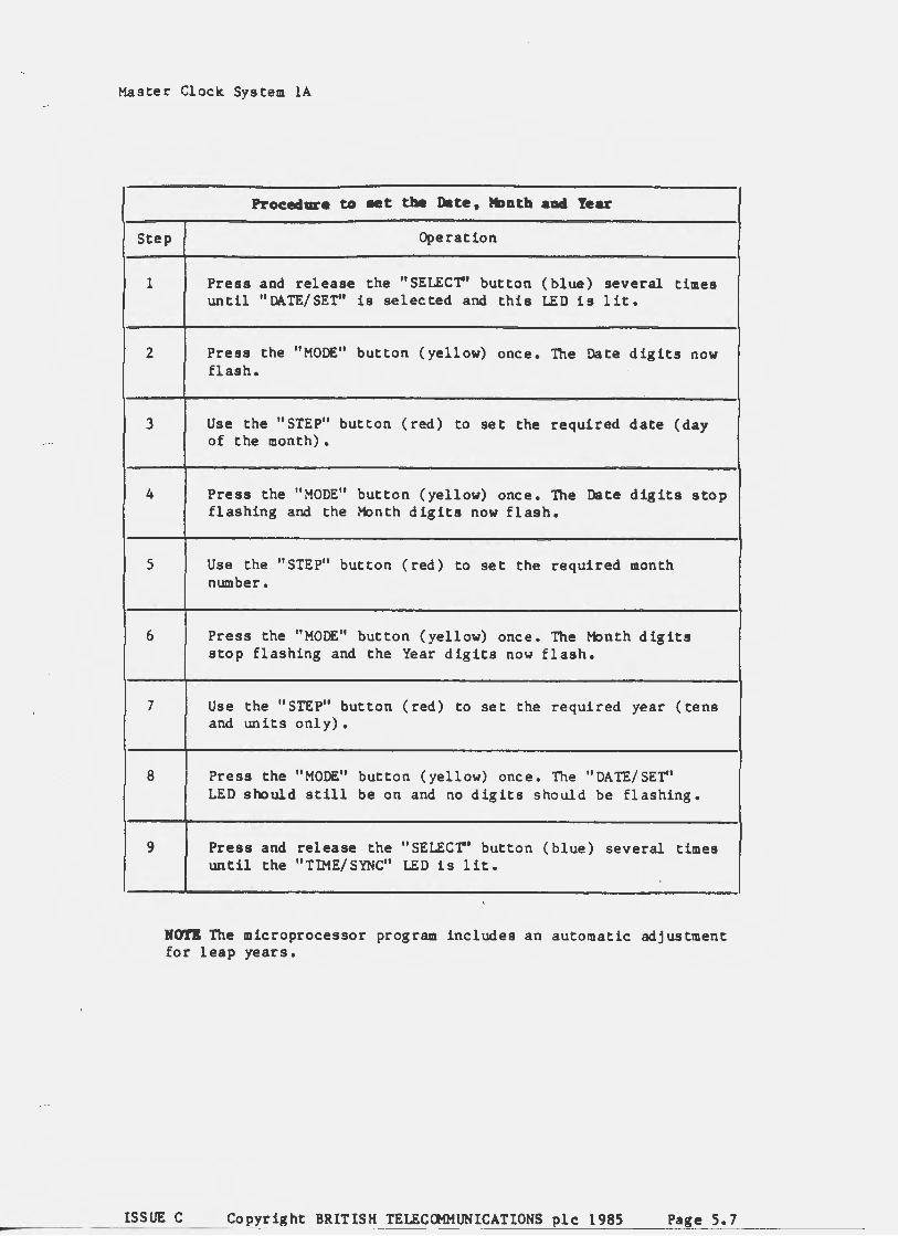
4.4.2. Setting the Date, Month and Year
Procedure to eet tt. Date, tloatla aDd Year
Step Operation
1 Press and release the "SELEC"r' button (blue) several times until "DATE/SET" is selected and this LED is lit.
2 Press the "MODE" button (yellow) once. The Date digits now flash.
3 Use the "STEP" button (red) to set the required date (day of the month).
4 Press the "MODE" button (yellow) once. The Date digits stop flashing and the Month digits now flash.
5 Use the "STEP" button (red) to set the required month number.
6 Press the "MODE" button (yellow) once. The Month digits stop flashing and the Year digits now flash.
7 Use the "STEP" button (red) to set the required year (tens and units only).
8 Press the "MODE" button (yellow) one e • The " DATE/ SET" LED should still be on and no digits should be flashing.
9 Press and release the "SELEC"r' button (blue) several times until the "TIME/ SYNC" LED is lit.
Mori The microprocessor program includes an automatic adjustment for leap years.
ISSUE C Copyright BRITISH TELECOMMUNICATIONS plc 1985 Page 4. 6

Master Clock System lA
4.4.3. Setting the QtT/BST Code
Step Operation
1 Press the "SELEC"r' button (blue) several times until "MISC" is selected and this LED is on.
2 Press the "MODE" button (yellow) once and use the "STEP" button (red) to set up the required code. The only four possible codes are;
00 - GMT this week and QtT next week 01 - QtT this week changing to BST next week 11 - BST this week and BST next week 10 - BST this week changing to QtT next week
3 Press and release the "SELEC"r' button (blue) until the "TIME/SYNC" LED is on.
4.5. TESTING
Verify that the Clock Electronic No. lA can be set up according to the instructions contained in the the charts in paragraph 4.4. Note that the 9 Volt nickel cadmium battery used for standby purposes will probably require several hours charging, in the clock, before it is capable of running the display.
Verify that the Clock Electronic lA runs after setting up. Check that all the facilities of the Clock will operate correctly. Check the oscillator frequency with an oscilloscope or frequency counter.
Check also the functions of the Relay Unit 33A, Control Unit 64A, and Distribution Unit SA, verifying that the correct outputs appear on strip connector TBA in the Distribution Unit.
The plug on the l'bunting must now be changed to the right socket and all the above tests repeated for the right half of the System.
ISSUE C Copyright BRITISH TELECOMMUNICATIONS plc 1985 Page 4.7

Master Clock System lA
4. 6. BRINGING INTO SERVICE
To guard against any services being affected by early component failure ensure that the Master Clock System lA is running for at least 24 hours before putting it into exchange use. It is necessary to repeat all tests before starting to changeover from the old clock system.
MOri Care must be taken not to affect tariff equipment during re-wiring and change over to the Master Clock. Check tariff equipment frequently to ensure that no interuption occurs.
Record the Strip Connector TBA to exchange connection details (rack etc) for future reference, and send a photo-copy or list of outputs used to TIIQ/AES 2.1.4. This is required to help determine future requirements.
4. 7. REPLACING EXISTING CLOCK 36
The Clock Electronic lA should be mounted in the allocated position and Cord Connection 69A plugged into the socket underneath the Clock. Check that the battery is in it's compartment but do not connect it at this stage.
Follow the supplied instructions to modify the exchange wiring to replace the existing clock with the Clock Electronic lA.
4.7.1. Cord Connection 69A
The following table gives details of the cable connections.
SI<B Signal Name Pulse Colour Comment Connection No.
SI<B2 Earth Red SKB3 -sov Black SI<B4 6 sec pulse P4 yellow/white SKBS l sec pulse P3 orange/white SKB6 30 sec equipment pulse P2 red/white SKB7 30 sec clocks pulse Pl black/white
SI<Bl4 Data Clock leg A grey ) twisted SKB15 Data Clock leg B orange }pair
If the Data Clock facility is not required the orange and grey twisted pair should be cut back or terminated on spare tags.
4. 7. 2. QIT 34 Relay IJn it Convertion
GMT 34 is converted by changing relays AR, BR, CR, OR to battery backed operation, and adding diode quenching to protect the transistor outputs of the Clock Electronic lA.
Details of this conversion work is given in full in IS IS TXA/ MEP/ A092.
ISSUE C Copyright BRITISH TELECOMMUNICATIONS plc 1985 Page 4.8

•
Master Clock. System lA
4. 7. 3. Advance/Retard Key
The Advance/Retard Key is provided on the Control Unit for the cocaplete System and is not present when only the Clock. Electronic lA is used. This can be overcome by putting a 3 way switch into the 30 sec clock. wire to the QtT. The first position on the switch disconnects the normal feed in order to Retard, the second position being that for normal operation ie. 30 sec supply and the third position switches to the 1 sec supply in order to Advance.
4.7.4. Setting up the Clock.
Carry out the operations listed in paragraphs 4.4.1. and 4.4.2.
4. 7. s. Testing
Carry out the tests 1 isted in paragraph 4. 5.
ISSUE C Copyright BRITISH TELECOMMUNICATIONS plc 1985 Page 4.9

r
Master Clock. System lA
Section
5. 1.
5.2.
5. 2. 1. 5.2.2. 5.2.3. 5.2.4. 5. 2. 5. 5.2.6.
5. 3.
5. 3. 1. 5. 3. 2.
5.4.
5. 4. l. 5.4.2. 5.4.3.
ISSUE C
SECTION 5 - MAINTENANCE INFORMATION
SECTION 5 CONTENTS
Title
INTRODUCTION
OPERATION
Manual Synchronisation TIMLOCK Synchronisation Greenwich Mean Time/British Summer Time Changes Advance or Retard Changeover Resetting the Clock.
FAULT CONDITIONS
Clock. Electronic lA Other Units
ROliTINES
Weekly Yearly 3 Yearly
Copyright BRITISH TELECOMMUNICATIONS plc 1985
Page No.
s. 2
s. 2
5.2 5.3 5. 3 s. 5 5.5 5.6
5.8
5.8 5.8
5. 8
5.8 5. 8 5.8
Page 5.1

Master Clock. System lA
5.1 INTRODUCTION
This section provides operating instructions and maintenance procedures required to run the Master Clock. System lA.
ROTI After completing any of these operations or procedures check. that all Wall Clocks and other dependant equipment are correct and working.
5. 2. OPERATION
The Master Clock. System lA derives the time signal from a free-running quartz crystal oscillator and is therefore subject to drift. The errors are expected to be less than plus or minus three seconds per week.. However, if left uncorrected the drift could accumulate to give an unacceptably large error.
There are two fundamental synchronisation modes in which the Master Clock. can be operated and these are known as TIMLOCK and Manual.
5. 2. 1. Manual Synchronization
If the Clock. is not syschronized for ten days the Clock continues to run normally but the "SYNC FAIL" (a low-priority deferred alarm) LED is on. A new ten day period is restarted, and if relevant the alarm is cancelled, whenever the Clock is properly re-synchronized.
Manual synchronisation involves giving the Clock a manual signal on an exact minute. The microprocessor computes the time error and takes the appropriate action.
The following sequence assumes the Clock. is within !20 seconds of the correct time.
Procedure to aanually resJilc broniee the Clock
Step Operation
1 Press and release the "SELEC'r' button (blue) several times until "TIME/ SYNC" is selected and this LED is lit.
2 Press the "MODE" button (yellow) once. The seconds digits now flash.
3 Listen to the speaking clock and wait for an announcement referring to an exact minute. On the third pip of this announcement, press "STEP" button (red). The seconds display will stop flashing. The "TIME/ SYNC" LED should remain lit.
'
ISSUE C Copyright BRITISH TELECOMMUNICATIONS plc 1985 Page 5.2

r
Master Clock System lA
If, at the time of the signal, the "seconds" display was between 00 and 20, the microprocessor assumes that the Clock was fast by this amount, and reduces the effective crystal frequency by one 64th for a given time to correct the error. (This means that a four second error will take about four minutes to correct). During this period the "CORRECTION IN PROGRESS" LED flashes slowly (once per second).
If the "seconds" display was greater than 40, the microprocessor assumes that the Clock was slow and increases the effective crystal frequency by one 64th. The "CORRECTION IN PROGRESS" LED flashes quickly (twice per second).
Note that the correction rate is the same in both cases.
If the display was between 20 and 40 seconds no corrective action would be taken automatically. It will be necessary to confirm that the stanby clock is correct, to changeover to the standby clock (paragraph 5.2.5.) and then reset the clock (paragraph 5.2.6.).
5.2.2. TIMLOCK Synchronization
When running normally, the "CORRECTION IN PROGRESS", LED should flash once every ten seconds, in time with the third pip. Synchronization errors of less than one 64th of a second are ignored, but if the error is greater than this, automatic corrective action is taken as described for manual correction.
When the speaking Clock is adjusted, the Clock mode is changed to "pip-search" (code 03 on the LCD, not programmable) if normal synchronisation is lost for one minute. If the "pip-search" is successful within one further minute the Clock re-synchronizes itself and reverts to normal. If unsuccessful, the "SYNC FAIL" LED lights.
The "SYNC FAIL" condition will also arise if the spealdng clock feed is interrupted for more than two minutes.
Under "SYNC FAIL" conditions the Clock must be manually resynchronised as described in paragraph 5.2.1.
5.2.3. Greenwich Mean Time/ British Standard Time Changes
The Clock will carry out <J1T/BST changes automatically • . This is arranged by setting the Clock to one of 4 codes during the week preceeding the time change. TI E6 GOOlO Twice Yearly Change of Time paragraph 15 also refers.
During normal Summer months the code should be left on "11" indicating BST for this week and next week.
When the change back to <J1T is due, the code should be changed to "10". This may be done at any time during the 6 days before the actual change is due.
' During normal Winter months the code should be left at "00".
When the change to BST is due, set the code to "01" at any time during the 6 days before the actual change is due.
ISSUE C Copyright BRITISH TELECOMMUNICATIONS plc 1985 Page 5.3

_/"-.
Master Clock. System lA
Proc:edure to cbaqe tt.. QfT/BST code
Step Operation
1
2
3
Press the "SELECT'' button (blue) several times until "MISC" is selected and this LED is on.
Press the "MODE" button (yellow) once and use the "STEP" button (red) to set up the required code. The only four possible codes are;
00 - GMT this week. and QiT next week. 01 - QiT this week. changing to BST next week 11 - BST this week and BST next week 10 - BST this week changing to QiT next week
Press and release the "SELECT'' button (blue) until the "TIME/SYNC" LED is on.
If either "01" or "10" has been set, the "AUTO QiT/BST CHANGE SET" LED will be on. The actual changes occur on a Sunday morning as de tailed below.
Code "01" - The Oock will "jump" from 00: 59: 59 (GMT) to 02:00:00 (BST). The QiT/BST code will be altered to "11" by the microprocessor, which will also generate 120 extra pulses on the 30-second clock output (if the advance/retard k.ey has been left in the normal position). Ihring this time the "NORMAL" LED flashes twice per second.
Code "10"- The time will change from 01:59:59 (BST) to 01:00:00 (QiT). The QiT/BST code will be altered to "00" and the 30-second clock out put will be held off for one hour (if the AIR key is normal) during which time the "NORMAL" LED flashes twice per second.
The 52 and 1 hr outputs are also corrected automatically according to the code selected.
s. 2. 4. Advance or Retard
The usual Advance/Retard facilities for 30 second clock pulses are provided in the Control Unit 64A, but these are guarded by the microprocessor to prevent pulses being split or shortened. Ihring Retard the red RETARD LED is lit and no pulses are produced. During Advance the red ADVANCE LED is lit and pulses are produced once per second.
ISSUE C Copyright BRITISH TELECOMMUNICATIONS plc 1985 Page 5.4

Master Clock System lA
When the automatic GMT/BST facility is used, an automatic Advance or Retard is initiated even though the Advance/Retard key is in the normal position. In these circumstances the "NORMAL" LED flashes twice per second. If the Advance/Retard key is operated during this procedure, the automatic advance or retard output is cancelled and the output is once more key-controlled. The Clock will still continue to show the correct time.
The facility to advance or retard individual wall clock circuits is built into the Distribution Unit SA.
To retard an individual wall clock circuit remove the fuse for the required number of pulses.
To advance a particular circuit set the rotary select switch to the required circuit. Set the switch to 1 sec • This will cause all the clocks on that circuit to step at 1 sec rate. After the required number of pulses have been given then restore the switch to the 30 sec posit ion.
The rotary switch can also be used to monitor pulses on any particular circuit.
s. 2. s. Changeover
Pulse supply changeover is by means of the 71 way plug and sockets mounted between the two Clocks. Should it be necessary to change the output pulses from one Clock to the other move the plug (PLC), from one socket to the other.
Procedure to cbuge tbe output paleea fro. one Clock to another
Step Operation
1 Ensure that the Clock to which you are changing is set to the correct time.
2 Avoid attempting changeover when other pulses are likely to occur eg. on 1/2 hours, hours, 1 pm and tariff chang~ver times. Imediately af~er a 30 sec pulse has occured is probably the best point at which to change the PLC plug from one socket to the other. (Try to changeover before the next 6 sec pulse occurs.)
3 Check that the pulse LEDs are still flashing and that all systems using the clock pulse are still correct eg. tariff equipment etc.
'
ISSUE C Copyright BRITISH TELECOMMUNICATIONS plc 1985 Page 5.5

{'
Master Clock System lA
5.2.6. Resetting the Clock
Procedure to reMt the Clock
Step Operation
1 Set the Clock a few minutes fastt to allow time for completion of all setting up operations t before starting the Clock in synchronisation with the Speaking Clock.
2 Press and release the "SELECT'' button (blue) several times until "TIME/ SET" is selected and this LED is lit.
3 Press the "MODE" button (yellow) once. This holds the seconds at zero and flashes the hour digits. (The Clock is initialised ln this state when power is first applied).
4 Use the "STEP" button (red) to set the hour required.
5 Press the "MODE" button (yellow) once. The _hour digits stop flashing and the minute digits now flash.
6 Use the "STEP" button (red) to set the minute required t Le. a few minutes ahead of the current time.
7 Press the "MODE" button (yellow) once. The minute digits stop flashing and the seconds (still held at zero) now flash.
8 Dial the Speaking Clock.
9 To start the Clock press the "STEP" button (red) when the actual time (third pip) coinci~es with the time shown on the liquid crystal display. The Clock will now run with the seconds incrementing normally. The "TIME/SET" LED is turned off and the "TIME/SYNC" LED is now on.
HO'l'B during the time-setting operations (i.e. when the "TIME/SET" LED is on and any pair of digits is flashing) the seconds are held at zero and no output pulses are produced.
ISSUE C Copyright BRITISH TELECOMMUNICATIONS plc 1985 Page 5.6
Master Clock. System lA
Procedure to • t tbe Date, MDDtb aDII Year
Step Operation
1 Press and release the "SELEC'r' button (blue) several times until "DATE/SET" is selected and this LED is 1 it.
2 Press the "MODE" button (yellow) once. The Date digits now flash.
3 Use the "STEP" button (red) to set the required date (day of the month).
4 Press the "MODE" button (yellow) once. The Date digits stop flashing and the Month digits now flash.
5 Use the "STEP" button (red) to set the required month number.
6 Press the "MODE" button (yellow) once. The tobnth digits stop flashing and the Year digits now flash.
7 Use the "STEP" button (red) to set the required year (tens and units only).
8 Press the "MODE" button (yellow) one e. The "DATE/ SET" LED should still be on and no digits should be flashing.
9 Press and release the "SELEC'r' button (blue) several times until the "TIME/ SYNC" LED is lit.
HOT.I The microprocessor program includes an automatic adjustment for leap years.
ISSUE C Copyright BRITISH TELECOMMUNICATIONS plc 1985 Page S. 7


