master level thesis - diva portal1232821/fulltext01.pdfmaster level thesis european solar...
TRANSCRIPT

Master Level Thesis
European Solar Engineering School
No. 235, June 2018
A Comprehensive PV Systems Installation Guide and Designing a Roof-Based PV System as a
Demonstration System for Troubleshooting Errors in PV
systems Installations
Master thesis 30 credits, 2018 Solar Energy Engineering
Author: Ahmed Hathout
Supervisors: Désirée Kroner
Examiner: Ewa Wäckelgård
Course Code: EG4001
Examination date: 2018-06-07
K
Dalarna University
Solar Energy
Engineering

i
ii
Abstract
The purpose of the thesis was to make a comprehensive guide for PV systems installers and engineers, using the best practices and following the applicable regulations and standards for the mechanical and electrical installations of PV systems. The guide includes all the different aspects of a PV system installation including different types of roofs and mounting structures, fire safety, height safety and fall protection, installation precautions, electrical and mechanical installations, safety gears and finally system commissioning. The guide was developed by reviewing the various standards and best practices deployed in various countries that are pioneers in PV installations as Germany, UK and the US in the period from 2006-2018. A troubleshooting errors scheme was conducted to help installers track down operational faults in a PV system. Installers will be able to identify problems of old or newly installed PV systems according to few procedures to resolve operational problems. In addition, a PV system was designed on the rooftop of Högskolan Dalarna in Sweden. The system will be used as a learning platform for installers in a course that will be introduced on the University’s campus, aimed at educating installers on PV systems installations. The designed system mainly focuses on flat and pitched roofs installations. The system was designed with the main priority to benefit installers working on and installing the system. Performance ratio and energy yield of the system were not emphasized when designing the system. It was specifically designed to match the objectives of the university’s installer’s course to be conducted on the campus. The designed system consists of two sub-arrays with two different mounting structures. The first one was a pitched roof mounting structure installed on a small hut on the university’s rooftop, and the second sub-array was a ballast mounting system directly situated on the roof surface with no penetrations to its surface. The system was designed on Sketchup software as a 3D model, simulated in PVsyst for energy yield forecast and losses evaluations, drawn as a single line electrical diagram on AutoCAD and lastly, a bill of materials was conducted with all the necessary components and parts to install the system on the rooftop. Results from the simulated system shows a steep drop in energy yield during the winter months, energy losses due to shading effects of approximately 5 % and minimal other system and cables losses were recorded. A study visit for a pitched roof PV system installation to be carried out by a group of six Swedish students was conducted. A discussion about the installation procedure, major mistakes and lack of practical knowledge by the engineering students were analyzed. Possessing knowledge of PV systems installations is of great importance not only to installers, but to solar design engineers. It is a necessity that engineers poses the fundamentals of installing a PV system and follow the applicable standards and best practices during systems design and execution.
iii
Acknowledgment
I would like to thank my supervisor Désirée Kroner for her immense help, guidance, dedication and knowledge. I am grateful for her full support all the way to complete this thesis. I would also like to thank the Solar Energy Engineering department staff for their relentless efforts to share their knowledge and help to me and my colleagues to become Solar Engineers. I would like to thank my family, my two sisters and especially my parents; without their limitless support, I wouldn’t be here in Sweden. Thank you for giving me this opportunity.

iv
Contents
................................................................................................................................................... 1
1 Introduction ................................................................................................................................... 1 Aims ......................................................................................................................................... 1 Method .................................................................................................................................... 1
2 Literature review ............................................................................................................................ 3 Roofs ....................................................................................................................................... 3 2.1.1. Pitched roofs .................................................................................................................. 3 2.1.2. Mounting systems for pitched roofs .......................................................................... 3 2.1.3. Flat roofs ........................................................................................................................ 6 2.1.4. Mounting systems for flat roofs .................................................................................. 6 2.1.5. Free standing systems ................................................................................................... 7 Fire safety ................................................................................................................................ 8 2.2.1. Causes of fires in PV systems ...................................................................................... 8 2.2.2. Hazards in PV systems ............................................................................................... 10 2.2.3. Guidelines for PV systems installations ................................................................... 10 2.2.4. Implementing products and technologies for fire safety ...................................... 12 Height safety and fall protection ....................................................................................... 13 2.3.1. Personal Fall Arrest Systems (PFAS) ....................................................................... 13 2.3.2. Personal fall restraint systems ................................................................................... 14 2.3.3. guardrail systems ......................................................................................................... 14 PV Systems Installation Precautions ................................................................................. 14 2.4.1. Mitigating Electrical and Mechanical Hazards ........................................................ 14 2.4.2. System Installation Plan ............................................................................................. 17 2.4.3. Safety plan .................................................................................................................... 18 PV Systems Installation ...................................................................................................... 18 2.5.1. Safety gear .................................................................................................................... 18 2.5.2. Electrical Components Installation .......................................................................... 19 2.5.3. Mechanical Components Installation ....................................................................... 21 2.5.4. Water Tightness ........................................................................................................... 27 2.5.5. Signs and Labels .......................................................................................................... 31 System commissioning ........................................................................................................ 32 2.6.1. System documentation ............................................................................................... 33 2.6.2. Visual Inspection ......................................................................................................... 34 2.6.3. Testing the system ....................................................................................................... 34 2.6.4. Maintenance of PV systems....................................................................................... 40 Troubleshooting Errors Scheme ....................................................................................... 41
3 System Modelling, Calculations and Simulation ..................................................................... 46 Building location and orientation ...................................................................................... 46 Design considerations ......................................................................................................... 46 System Design ...................................................................................................................... 47 3.3.1. System Calculations .................................................................................................... 48 3.3.2. Sketchup drawing ........................................................................................................ 50 3.3.3. PVsyst simulation ........................................................................................................ 52 3.3.4. Electrical drawing ........................................................................................................ 53
4 Results and Discussion ............................................................................................................... 55 System Design ...................................................................................................................... 55 System Performance ............................................................................................................ 55 Bill of materials .................................................................................................................... 56 Uncertainties ......................................................................................................................... 57 Installation improvements .................................................................................................. 57 Study visit .............................................................................................................................. 58 Limitations ............................................................................................................................ 60
v
5 Conclusions .................................................................................................................................. 61 Future work ................................................................................................................................. 61
6 References .................................................................................................................................... 62
7 Appendix ...................................................................................................................................... 64 Appendix A: The initial two design scenarios considered for Dalarna University rooftop ...................................................................................................................................................... 64 Appendix B: Luxor Module LX-260P/156-60+ datasheet.................................................. 65 Appendix C: Inverter SMA SUNNYBOY 3.6 datasheet ..................................................... 67 Appendix D: PVsyst simulation report for the designed PV system on Högskolan Dalarna roof ................................................................................................................................ 71 Appendix E: Questionnaire for PV Installation Companies ............................................... 75
vi
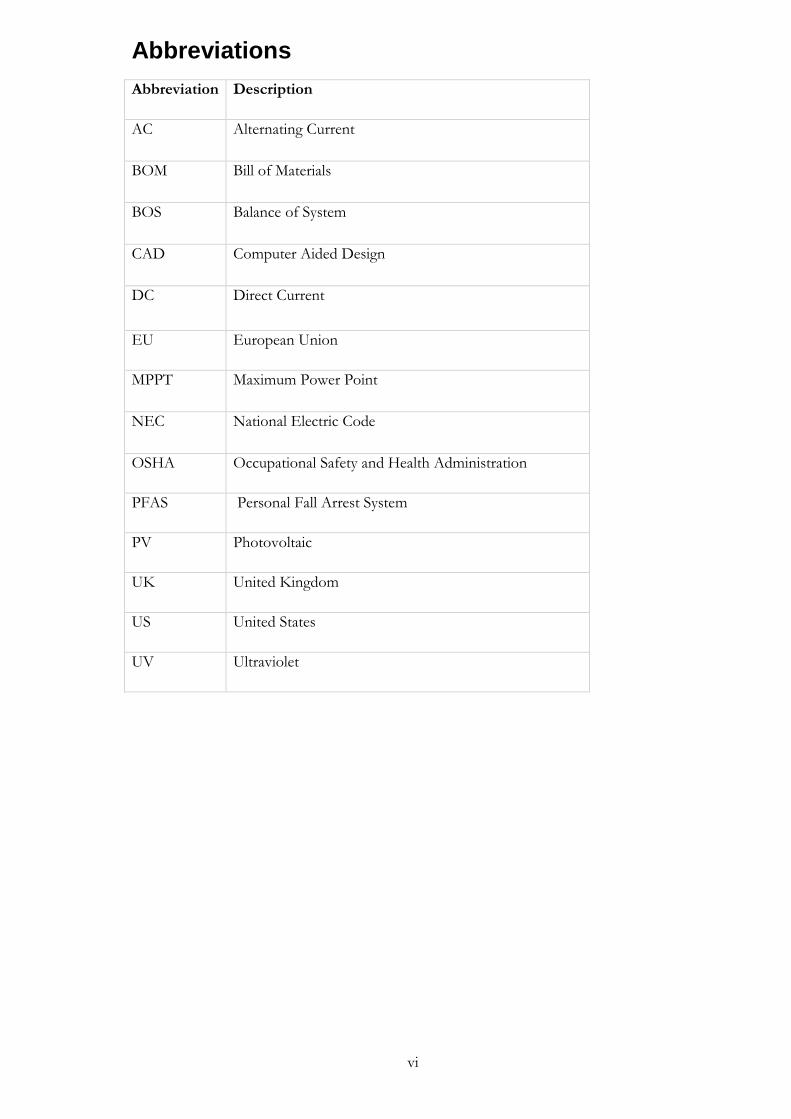
Abbreviations
Abbreviation Description
AC Alternating Current
BOM Bill of Materials
BOS Balance of System
CAD Computer Aided Design
DC Direct Current
EU European Union
MPPT Maximum Power Point
NEC National Electric Code
OSHA Occupational Safety and Health Administration
PFAS Personal Fall Arrest System
PV Photovoltaic
UK United Kingdom
US United States
UV Ultraviolet

vii
Nomenclature
Symbol Description Unit
A Cable cross section mm2
𝐼𝑠𝑐 Short circuit current A
K Electrical Conductivity of copper m/Ω mm2
P Transferred power W
𝑉𝑜𝑐 Open circuit voltage V
𝑉𝑜𝑐𝑚𝑎𝑥 PV module’s temperature corrected maximum voltage V
𝑉𝑠𝑡𝑟𝑖𝑛𝑔 System voltage V

1
1 Introduction The Swedish photovoltaics market has grown annually at a steady pace since the year 2007. At the end of 2016, it was reported that the on-grid connected PV capacity was fifteen times more than their off-grid counterpart. Roof mounted PV systems represented most of the installed on-grid installations. An impressive 94 % of the installed on-grid systems are either owned by small houses or are built on companies, public buildings or farms. At the end of 2016, only 6 % of the grid connected systems were free standing systems. [1] The total PV installations in Sweden in 2016 were 79.2 MW, recording a 63 % growth rate when compared to 2015 which peaked at 49.4 MW [1]. According to the Greenpeace reports and the European Photovoltaic Industry Association (EPIA), the PV sector employs approximately 33 individuals per MW installations [2]. If the same rate of growth; 63 %, continues in Sweden at the end of 2018, then there will be an increase in the total PV installations by 81 MW compared to 2017. Accordingly, the number of PV installers and engineers will have to increase to meet the demand. An emphasis on the proper technical education and training for installers and engineers must be made as a response to most countries in the EU committing to become fully renewable by 2040 [2]. Installers must be equipped with solid knowledge on handling, working and installing complex electrical and mechanical equipment of a PV system.
Aims
There are two aims for the thesis. Firstly, a comprehensive study on the different types of PV mounting systems and all the necessary steps required to install a complete PV system from handling PV modules, to system testing and commissioning. The study is aimed towards PV installers and engineers in Sweden that will need a detailed technical guide for PV systems installation. A troubleshooting errors scheme is to be developed to show installers the necessary steps they have to follow in case of a PV system failure, to rectify the source of error. Thirdly, a roof-based PV system on Dalarna University rooftop will be designed using three simulation softwares. PVsyst for performance analysis and equipment selection, Sketchup software for 3D modelling of the system, and AutoCAD software for drawing the system’s single line electric diagram. A bill of materials (BOM) will be formulated of all the system’s components to be ordered at a later date. The designed PV system is targeted as a practice system for installers and so, the performance and energy yield of the system are not a priority.
Method
The methodology will consist of detailed literature research, three simulations for the design of the proposed roof-based PV system and a formulation of a list of errors that installers can troubleshoot to ensure optimal system operation. The following sequencing will be carried out:
• Research and compile the different types of PV mounting systems including the ones designed for pitched roofs, flat roofs and standalone systems. The attributes of each mounting system will be discussed alongside the location and structural fixation of the mounting system in question.
• Research the different fire and height safety general protocols specifically in the EU, but also including the general guidelines used by California Fire Department
2
in the US due to California State being one of the pioneers and early adopters of PV systems.
• Roof-based PV system design at Högskolan Dalarna using PVsyst simulation software for performance analysis, equipment selection, shading losses and cable losses if relevant. Furthermore, a 3D model of the system will be drawn on Sketchup software with the correct dimensions of the building used for the PV system on the rooftop. A single line electric diagram of the designed system will be performed on AutoCAD with detailed layout.
• Review on the electrical and mechanical components installation including the necessary tools needed by the installer and the best practices to follow.
• Research on the best approach to manage, label and document the cables and routes in a PV system.
• Research on the system commissioning
• Develop a troubleshooting errors scheme for installers to follow in case of PV systems failures.
3
2 Literature review In the recent years, very few complete guides for PV installers were written. This section will contain all the necessary information for a PV system installer to begin installing a system from electrical and mechanical components to commissioning of the system.
Roofs
There are different types of roofs that are suitable for PV arrays installation. According to [3], these can be categorized as follow:
• Flat roofs with slope less than 5o
• Slightly sloped roofs with a sloping angle range from 5o – 22o
• Normally sloped roofs with an angle of 22o- 45o
• Steep roofs with slope angle exceeding 45o It is important to note that with curved roofs, there are different angles and exposure levels to irradiation. Thus, careful considerations when it comes to PV array design and strings wiring should be a priority to ensure optimal energy yield. [3]
2.1.1. Pitched roofs
Pitched or sloping roofs are the most common types of roofing for residential households. Their design structure is different from flat roofs. There are few characteristics and traits that are distinctive for pitched roofs.[3]
• The roof covering regardless of the material, acts as the first barrier to drain water.
• Rain water and any kind of moisture is slid from the sloped surface and accumulate at the lowest point of the roofing structure where it is cleared through a drainage pipe.
• Underfelt; also known as sub-roof is the second waterproof layer that completely prevents any water from penetrating the roofing structure. It is critical that this layer is not compromised during a PV system installation. Otherwise, additional water insulation must be added to the roof before commencing with the PV installation.
• Thermal insulation for the top floor of the building is necessary before starting a PV system installation process. PV modules during normal operation will reach high temperatures which can easily be transferred through a roof to a building’s envelope.
Pitched roofs can be accompanied by one of the following superstructures. Dormer windows, roof terraces, dome lights or skylights. It is mandatory to do shading and spacing analysis during the design phase of a PV system for these structures as they can hinder a PV array performance significantly. [3]
2.1.2. Mounting systems for pitched roofs
Roof mounted PV modules are installed with a grid made of aluminum or stainless steel above a structure’s roof covering. The roof covering is not altered during installation of the metal grid and it should hold its water proof characteristics. The disadvantage of mounting systems for pitched roofs are the limited design possibilities due to the slope of the roof. Moreover, all the associated components from fasteners, electrical cables and connectors are exposed to various weather conditions. [3] The metal grid consists of three main components: The roof bracket, the mounting rails and finally module mounting. Mounting rails can be installed in two ways. Either by directly fixing it to a roof structure (rafter) or be attached to a roof’s covering without removing the covering and anchoring it to the rafter. The fasteners role is to fix PV modules in place on mounting rails. [3]

4
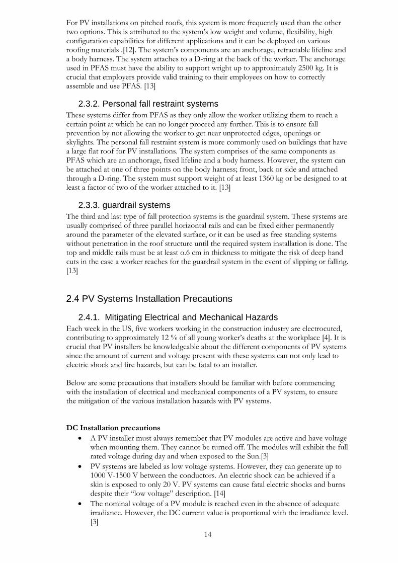
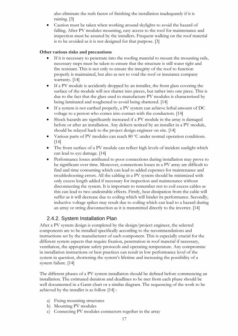
It is not possible to install PV modules on a roof without making fixing points that will hold mounting frames. The two choices available are rafter dependent and rafter independent solutions. Rafter independent solutions don’t require piercing into the roofing structure and are more flexible in positioning and design than rafter dependent solutions. However, care must be taken as rafter independent solutions are extremely reliant on the weight of load as they cannot withstand high loads as rafter dependent solutions. Wind, snow and load calculations must be performed in the design phase for rafter independent mounting solutions. [3] Roof hooks for concrete and plain tiles This is one type of hook designs for concrete or plain roof tiles. The hooks are tightly screwed into a rafter after removing the roof covering as shown in Figure 2.1. The hooks are designed so that their broad ridge (flange) is situated on the hollow part of the roof tile with a spacing of approximately 5 mm away from the surface as illustrated in Figure 2.2. If they are not pressed against the roof tiles, then they are positioned correctly. If the hook is preventing the roof tile from being situated in its original spot, then a cut out with a hammer or an angle grinder must be made at the point where the hook meets the roof tile. For plain tile roofs, a cut out must be made on the lower surface of the tile covering the hook, or the roof tile must be replaced with a smaller roof tile which may be more expensive and require more labor. For each cut out made for plain tile roofs, a titanium zinc sheet is inserted below the roof hook. [3]
Figure 2.1 Typical Roof hook
Figure 2.2 Cut out in a roof’s tile and roof hook placement
5
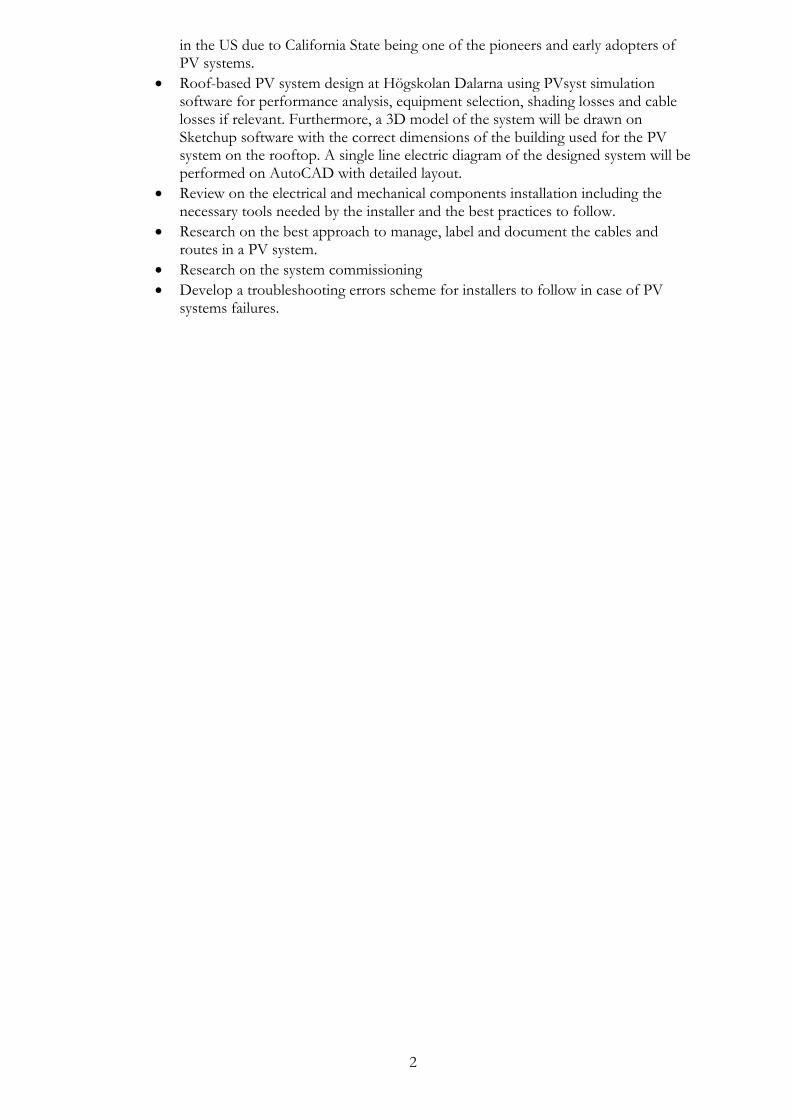
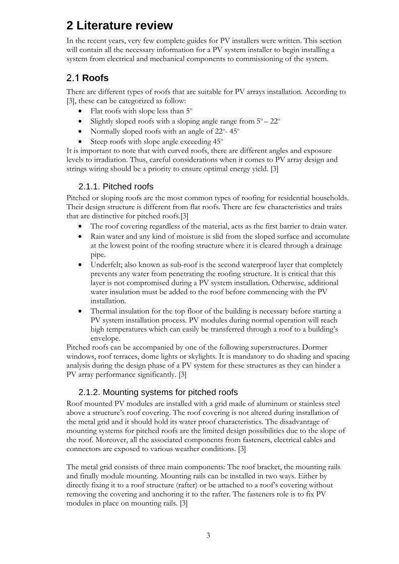
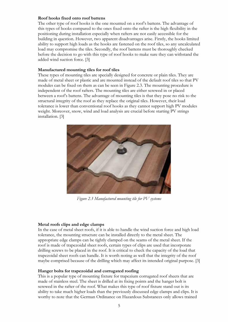
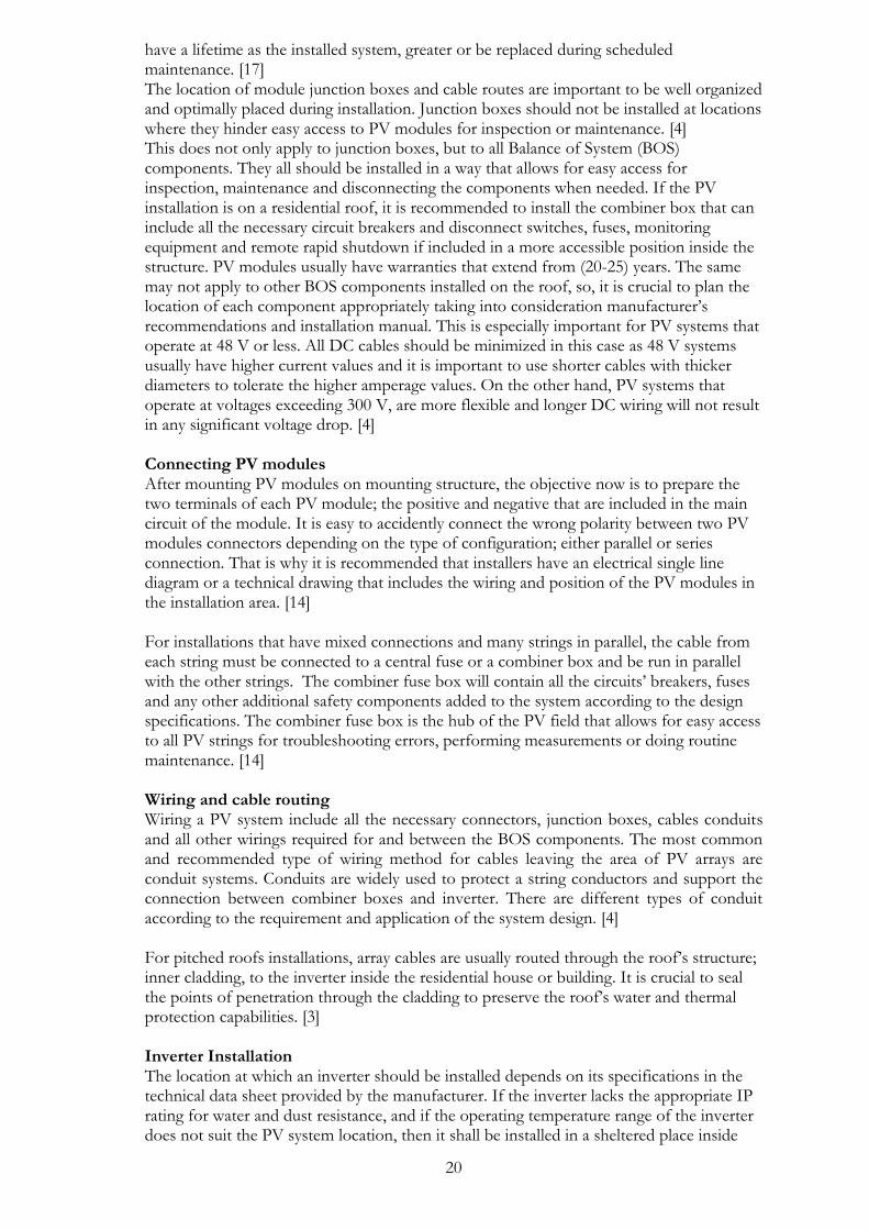
Roof hooks fixed onto roof battens The other type of roof hooks is the one mounted on a roof’s battens. The advantage of this types of hooks compared to the ones fixed onto the rafter is the high flexibility in the positioning during installation especially when rafters are not easily accessible for the building in question. However, two apparent disadvantages arise. Firstly, the hooks limited ability to support high loads as the hooks are fastened on the roof tiles, so any uncalculated load may compromise the tiles. Secondly, the roof battens must be thoroughly checked before the decision to go with this type of roof hooks to make sure they can withstand the added wind suction force. [3] Manufactured mounting tiles for roof tiles These types of mounting tiles are specially designed for concrete or plain tiles. They are made of metal sheet or plastic and are mounted instead of the default roof tiles so that PV modules can be fixed on them as can be seen in Figure 2.3. The mounting procedure is independent of the roof rafters. The mounting tiles are either screwed in or placed between a roof’s battens. The advantage of mounting tiles is that they pose no risk to the structural integrity of the roof as they replace the original tiles. However, their load tolerance is lower than conventional roof hooks as they cannot support high PV modules weight. Moreover, snow, wind and load analysis are crucial before starting PV strings installation. [3]
Figure 2.3 Manufactured mounting tile for PV systems
Metal roofs clips and edge clamps In the case of metal sheet roofs, if it is able to handle the wind suction force and high load tolerance, the mounting structure can be installed directly to the metal sheet. The appropriate edge clamps can be tightly clamped on the seams of the metal sheet. If the roof is made of trapezoidal sheet roofs, certain types of clips are used that incorporate drilling screws to be placed in the roof. It is critical to check the capacity of the load that trapezoidal sheet roofs can handle. It is worth noting as well that the integrity of the roof maybe comprised because of the drilling which may affect its intended original purpose. [3] Hanger bolts for trapezoidal and corrugated roofing This is a popular type of mounting fixture for trapezium corrugated roof sheets that are made of stainless steel. The sheet is drilled at its fixing points and the hanger bolt is screwed in the rafter of the roof. What makes this type of roof fixture stand out is its ability to take much higher loads than the previously discussed edge clamps and clips. It is worthy to note that the German Ordinance on Hazardous Substances only allows trained
6
individuals with a permit to drill though asbestos based fiber cement panels or an exception can be made if a form is applied stating that the building and roof structure are in an appropriate shape for repair or modification. [3]. In the case of structural difficulties that may require drilling directly into the metal roof structure, it is a necessity to seal the roof covering at the penetration point properly according to the right directives for the metal sheet. Failure to do so, will result in roof exposure to moisture invading the inner structure, which may result in long term damage [4]. The same rules can apply to Sweden, so it is important to check with the local municipality.
2.1.3. Flat roofs
There is no definite angle that can characterize a roof as a flat one. But, most commonly a flat roof is defined as the one between sloping angles of 5o to 11o. In the technical and structural terms; flat roofs have roof sealing to prevent the structure from any water penetration, while pitched roofs have roof covering. This means that flat roofs have only one water drainage level via a downpipe inside the building or weep holes at the very edge of the roof. [3] Resistance insulation must be present in flat roofs and it should have certain characteristics like being water and frost proof, resistance to rotting and is dimensionally stable to be walked on [3].
2.1.4. Mounting systems for flat roofs
Mounting systems design for flat roofs are more diverse and flexible than pitched roofs. The orientation and location of PV arrays can be easily accommodated with flat roofs. It is worth mentioning that care should be taken when dealing with flat roofs installations as the default roof covering is easily prone to damaging by the mounting structure which can result in substantial damage to the roof that is not easily reparable as pitched roofs. Once PV strings are installed, access to the roof will be restricted in most cases. Thus, extreme care should be taken during the design and installation phase of mounting systems to ensure that a roof can reliably function during the lifetime of a PV system. [3] The same mounting principle for pitched roofs is carried on to flat roofs. A metal grid is fixated above the roof covering and PV panels are mounted on it. The biggest difference comes from the design perspective as in the case of flat roofs, the inclination angle can be decided as desired by the solar engineer to achieve the maximum solar radiation on the panels and eliminate the shading effects on PV modules. [3] Ballast mounts For ballast mount systems, the mounts are fixed on a roof covering without any penetration [3]. They rely entirely on the weight of PV modules, other system connections and extra materials like concrete or gravel to add extra weight to the mounting structure to hold PV modules in place [4]. Generally, PV strings can be installed on flat roofs without voiding their warranties. However, the installation must be done in collaboration with a representative from the roofing company or manufacturer to make sure the added ballast mounts don’t violate the terms of warranty or insurance [3]. Detailed analysis must be conducted with ballasted mounting systems because they impose great load on a roof [5]. Moreover, wind data analysis must be done before installation to make sure a PV array is not uplifted by wind. It is common to see many ballast mounting systems limited to an inclination angle of 20o or less to decrease wind uplift forces [5]. The method of roof fastening on flat roofs is of great consideration. Whether the system should be fixed to a roof (Anchored) or free standing (Ballast mounting) depends on the wind and load calculations [3]. The type of ballast used will depend on the type of roof and the intended load. Roofs that are characterized by concrete blocks or gravel as loading, can be used as ballast for PV
7
strings by distributing the load equally. Concrete slabs or brackets can be used if the roof is capable of withstanding the load. The slabs can be used directly as the base to which the mounting frames will be fixated on; or the concrete can be inserted into designated channels at the feet of the mounting structure. [3] According to [3], gravel coverings can weigh approximately 90 kg/m2 and concrete blocks weigh 125 kg/m2. Tray systems made of UV resistant plastic or fiber cement are filled with these concrete blocks or gravels to reach the optimal weight to support the mounting structure. PV modules can be fixed directly on the tray if it has the exact dimensions of the module or by fixing the modules on mounting rails attached to the tray. There are few advantages for tray systems. Firstly, they are aesthetically pleasing and organized on the roof. Secondly, they are cost effective because the ballast material whether it is gravel or concrete can be added directly to the trays if they are on the roofs without the need of additional transportation. [3] It is crucial to reiterate that when choosing ballast mounts as the choice for a PV system installation, following buildings regulations and codes is a must. Ballast mounting system suppliers include the necessary tables in their products for the engineer to choose the right ballast weight and dimensions. The ballast material is not included in the delivery. It has to be obtained locally or from a third party. Checking and rechecking the loading capacity of the roof of choice is the most important step for ballast mounts. If it cannot be derived, a structural engineer must be consulted for load calculations. [3] Attached or anchored systems Attached systems are fixed on a roof through penetration in a roof’s surface [5]. They are used in the case when ballast mounted systems are not structurally possible to be fixated on the roof [3]. The PV array is mounted on the supporting frames which are anchored directly to the roof surface by various methods including screwing, welding or by curbs integrated into the roofing [5]. The penetrated points through the roof must be sealed appropriately so that the roof can retain its waterproof quality [3]. Some advantages of anchored systems include the flexibility added to the design engineer to make specific requirements for the mounting frames and live loads, the reduced loads on the roof and hence the structure, the possibility to locate, level and tilt the array at the desired angle. [5]
2.1.5. Free standing systems
Free standing PV systems constitutes an important percentage in recent years PV installations, especially for more than 1 MW sized PV plants [3]. Mounting systems for free standing installations require the same traits as the other types of mounting systems like sturdiness and different weather resistance conditions. The foundation and materials used for the mounting systems depend on the load, quality and pH level of the ground in use. [3] Free standing or ground mounting systems are relatively more expensive than pitched roof systems. PV arrays are fixated on mounting rails that are fixed to a steel structure to be placed relatively deep in the ground or attached to blocks made of different materials like concrete. [6] Some advantages of free standing mounting systems include cooler PV cell temperatures especially in open areas as air can easily circulate around PV modules which will result in lower average cells temperature compared to roof mounting systems. Furthermore, they are safer and less complicated when installing the hardware than roof mount systems as they are installed on the ground and there are no need for height safety protocols. Free standing systems are easier to access due to the huge footprint of the PV power plant; thus, their maintenance and fault detection are easier to perform. [6]
8
Concrete foundations The concrete bases are either formed as strip for the mounting system footing or as column foundation. Large concrete blocks are also an option if the soil is shallow. The mounting frames are added after the fixture of the concrete foundation and they can either be anchored or reinforced with the footings. [3] Steel screw and pile foundations In comparison to concrete foundations, steel screw or pile foundations are the most widely used type of foundations for fixating the mounting grid. They do not require complicated earthwork, they save time as the loads can be mounted immediately after putting the foundation in place and they are the most cost-efficient type of foundation for stand-alone installations. However, they require a ground with appropriate depth and they must be put into position perfectly without any signs of ‘tilt’ as they are sensitive to shear forces. A slightly tilted element, can make the mounting frame bent because of the PV load and this will increase tensions in PV modules. [3] Gabions Gabions are perforated wirework containers usually filled with rocks that are used as the foundation or the base of the mounting system. They can take volumes as large as 4 m3 and preferably they are fixated on a ground that is not shallow. Advantages of gabions are that they are straight forward to install and they can serve as accommodations for tiny animals around the PV field. [3]
Fire safety
PV systems designed according to the appropriate electrical codes, installed properly using the best practices, maintained and monitored regularly, don’t cause safety or health risks when performing under normal operation conditions [7]. However, as with all electrical systems, fire risk is a serious possibility that needs to be considered when designing a PV system. There are no international fire safety protocols that PV systems designers must adhere to, but rather guidelines to PV system installers, operation and maintenance personnel, firefighters and PV system owners in some PV leading countries [7]. Safety guidelines from Germany, United Kingdom (UK) and the United States (US) will be the primary focus.
2.2.1. Causes of fires in PV systems
According to [8], there were 180 out of 400 fire incident cases recorded in Germany, where PV systems were the direct cause of fire from the period of 1995 to 2012. It was concluded from the analysis that around 65 cases out of 180 were started in the DC section of a PV system, which makes it the dominant factor for a fire risk in a PV system. Around 50% of the fire causes were attributed to PV modules and inverters. The causes of fire recorded in the cases can be categorized into three parts. Mechanical design errors, poor workmanship by installers and other external factors. [8] Mechanical design errors
• Thin film modules with no frames that were mounted too close and tight to one another. This caused mechanical tensions resulting in glass cracking and breakage, leading to an electric arc.
• Mounting rails were tightly fixed next to module’s junction boxes causing shearing forces in junction boxes that resulted in an electric arc.
• Compromised junction boxes to various weather elements like rain and sun, which developed high humidity and internal air temperatures in the boxes, leading to stress development on the internal contacts, ending in an electric arc.

9
• Inverters and array’s junction boxes were found mounted on wooden slates or other combustible mounting material causing the fire to spread quickly across and inside the building.
• Lack of fire retardant sealing which acts as a buffer to prevent fire from spreading through the walls and joints, at the entrance of a rooftop’s PV strings cabling; causing electric arcs to enter inside the building from the rooftop.
Electrical installations design errors
• System’s cables were underrated which caused overheating of the cables and resulted in charred contacts.
• AC fuse installed at DC circuit. The fuse didn’t perform its function in interrupting the current, causing an electric arc.
• DC cables were installed on a sharp metal edge resulting in damage over time, thus short circuit and electrical arc.
• Terminals used were not with the correct ratings to be used with aluminum conductors. This caused fire because of the increase in contact resistance.
• Cabinets that were intended to be used indoor were alternatively used outdoors. This resulted in water penetration causing contacts degradation because of overheating, forming charred terminals and eventually loss of power.
• Some DC switches were underrated, resulting in overheating and formation of an electric arc causing fire.
• Inverters were found installed in unfit places exposed to different weather conditions or mounted on combustible material. The level of damage found ranged from an inverter breaking down to barns being completely burnt down.
Poor workmanship
• DC connector were improperly plugged in. This caused overheating, melting of the plug and the PV array output being interrupted. In some recorded cases, various damage levels to buildings were found.
• DC connector were either poorly crimped or not crimped at all. This caused electric arc and damage to buildings.
• DC connectors from different manufacturers mating together in the system, resulting in the overheating of hundreds of contacts in large PV systems installations. This resulted in expensive repairs and labor costs.
• The screw terminal in junction box was not fastened. This generated electric arc and a total destruction of the junction box. In one of the recorded cases, one building was destroyed as a result.
• Fuse was not properly placed or latched in its designated slot. This resulted in an electric arc and damage to the junction box.
• The lack of strain relief associated with the cables. This may have been a possible cause of contacts failure in the AC cabinet leading to fire.
• Module’s wires were mistreated and were used as handles. This caused tensions in the wires; pulling them slightly out of the junction box contacts. An electric arc was thus formed in the junction box.
External factors
• Cases of short circuit were found as a result of rodents chewing wire’s insulations; forming an electric arc.
• Damaged junction box because of lightning strikes which shorted the bypass diodes leading to a reverse in current.
• Short circuit and electric arc formation due to PV installer drilling long screws into the roof structure that penetrated hidden DC cables fixated beneath it.
10
2.2.2. Hazards in PV systems
During daylight, a PV module generates a relatively low DC voltage. But, when PV modules are connected together in series to form a string, the voltage output can be as high as 1000 V. [7]. The produced DC voltage is converted to an AC voltage by a PV inverter to be fed to the national local grid. If a fire is to occur in a PV array, the inverter can be shut down from the main fuse or by an AC circuit breaker. However, DC voltage that is being generated by PV modules will still be present on the roof in the DC cables. [7]. This poses few serious hazards for firefighters: [7]
• Electrical shock: PV systems remain energized and continue to produce high DC voltage even when the AC connection to the grid is shut down. This exposes firefighter to a possible lethal injection of voltage through his body causing a cardiac arrest if there is a contact with PV module’s wiring.
• Slip and fall hazard: If there is a space limitation and no clear wide pathway for firefighters on an inclined rooftop, a firefighter can slip on the glass surface of a PV module and fall.
• Roof collapse: PV modules have considerable weight and they add to the overall dead load on the roof. The roof may collapse under the immense weight and the weakening of the roof structure.
2.2.3. Guidelines for PV systems installations
There are guidelines that have been published in some countries where PV systems are prevalent such as the three countries demonstrated here. Germany The German Solar Industry Association has released design and construction guidelines for PV system’s designers and installers in “Fire protection-oriented planning, construction and maintenance of photovoltaic systems” [7].
1. Markings: It is crucial to put a PV sign on the building so as when a fire start, firefighters can recognize the existence of a PV system on the building and can act accordingly. It may be obvious to recognize a PV system, but in the case of darkness or heavy smoke from fire, it may take time to verify the existence of the system or the PV array maybe mistaken with other roof materials. Time is of utmost importance during a fire, hence a clear PV signage must be present to firefighters. According to VDE-AR-E2100-712 standard in Germany, a system layout diagram must be installed by the operators showing the different locations of the PV system’s components in the structure. The system layout diagrams have to be fixed to the different electric system’s connection points including distribution panels and junction boxes.
2. Roof space: There are different PV installation techniques associated to each roof type to ensure that there is an ample space for unobstructed operation for firefighters during fire.
• Pitched roof: Firefighters can access the ridge of a roof through clear pathway at the edge of one side of the roof. Not all of the roof surface is to be occupied by the PV panels. A distance of 0.99 m should be present at one of the edges.
• Flat roof: Firefighters can access the roof via clear wide routes along the building’s side near the edge.
• Large flat roof: Various access routes must be made during the installation process for each occupied area by PV arrays with maximum area dimensions of (40 m × 40 m). The minimum width of the route is 1 m and can be wider.

11
UK In the UK, Fire Protection Association (FPA) in collaboration with RISCAuthority which is a membership that includes a large number of UK insurance companies, have published a document for the best practices to protect people, properties and the environment from losses attributed to fire. [9]
1. A fire risk assessment should be undertaken before and after the installation of PV modules on all industrial and commercial buildings to comply with the Fire Safety Order 2005 or equivalent legislations present in Northern Ireland and Scotland.
2. The installation of PV systems up to 50 kW should be done by a company that is accredited by the Microgeneration Certification Scheme (MCS) and a certificate is issued upon the commissioning of the equipment by an installer recognized by MCS.
3. A ‘Fire service switch’ should be present at each location where there is a PV installation in an accessible position for firefighters in order to isolate the DC side of a PV system. The minimum function of the switch is to make sure that the DC side wiring inside the structure is voltage free. During the scheduled routine maintenance of the PV system, the fire service switch should be tested, and the measurements recorded, to ensure its operability.
4. A sign indicating the existence of a PV system on the building should be fixated at the supplier’s cut out or the consumer units, with a minimum measurement of the sign of 10 cm × 10 cm.
United States In April 2008, the California Department of Forestry and Fire Protection, published the guide “Solar Photovoltaic Installation Guide” aimed at PV systems installers [8]. The International Fire Code (IFC) which is one of the two main fire codes in the United States, is updated every three years and it adopted its fire codes requirements based on the recommendations and guidelines proposed by CAL FIRE guidelines [10]. It is worth mentioning that by March 2014, 23 American states have enforced the IFC 2012 which contains new criterias for PV systems designs to reduce the hazards firefighters have to deal with during fire outbreaks [10]. There are three main pillars for the essential requirements to implement in PV systems design: [10]
• Access: A minimum width of 1.83 m clear area around the edges of commercial roofs that exceeds 76.2 m × 76.2 m. The PV system designer can reduce the value of the minimum width to 1.2 m of clear area around the edges if any axis of the roof is less than 76.2 m.
• Pathways: The IFC mandates two clear pathways for firefighters. “Centerline Axis pathways” and “Straight line pathways” starting from a roof’s access area to ventilation, skylights and standpipes. The minimum width of the two pathways is 1.2 m. Furthermore, a 1.2 m clear area around the roof’s access hatch, and at minimum one pathway between the roofs access hatch and the roof’s primary access. In addition, all the aforementioned pathways must be able to withstand “The live loads” which are the firefighters and their associated equipment.
• Smoke ventilation: Vertical ventilation is sometimes used by firefighters in their operations as a mean to remove smoke arising inside the building. Thus, as to not compromise firefighter’s operations when there is a fire, the size of a PV array must not exceed 45.7 m × 45.7 m in distance in either direction of a commercial building. PV modules are also restricted to be installed approximately 0.9 m from the ridge on each of the two pitched roof slopes.

12
2.2.4. Implementing products and technologies for fire safety
There are different technologies and products available in the market that help mitigate and reduce the risk of a fire hazard in a PV system. Ground fault circuit interrupter (GFCI) Ground related faults, which involve the flow of current and power dissipation into ground conductors, can impose potential shock and fire hazards. If the current continues to flow to the grounded conductors, the result will be the formation of resistive heating and in some cases electric arcs; which can evolve into fire. The hazard of electric shock specifically is very prominent in that case as any human contact with uninsulated conductors; like PV modules outer frames, will be susceptible to a shock. [7] As a result of these safety concerns, ground fault protection circuits were widely used in PV systems since the year 1990. [7]. In the United States, the National Electric code (article 690.5) mandates all stand alone and roof mounted PV systems to have a ground fault protection circuit to detect, interrupt the current flow and shut down any affected PV module, connection, conductor or any other system component present in the DC side of a PV system including the output circuits. Furthermore, a PV system have to include an annunciator to give a visual warning that the GFCI was initiated, and that a manual reboot of the affected components is necessary. [10] Recently, a warning light like a red indicator light was required as a fundamental feature of ground fault protection circuit. The way GFCI functions is when there is an excessive flow of current to the ground, GFCI acts accordingly and put the grounded conductor in an open circuit state to prevent the build-up of ground faults. [7] Arc fault circuit interrupter (AFCI) An electric arc is the result of electrical energy discharge; resulting from current, flowing through a resistive medium like air. The high level of air resistance causes heating, triggering an electric arc which can lead to a fire. Reasons behind an electric arc in PV systems include poor cables or connectors’ installations, or damaged and degraded cables, and poor soldering points inside a junction box which may compromise the integrity of the connection. [7] The hazard of an electric arc in the AC side of a PV system is mitigated due to the oscillating characteristic of an AC current which makes an AC electric arc self-extinguishing. On the other hand, the DC side of a PV system is more susceptible to an electric arc, as DC can keep generating sustainable supply of current to feed the electric arc, which can easily spread out to the surrounding materials and components and result in a fire if the current supply is not interrupted. [7] There are three types of electric arc fault that may occur in a PV system:
• Series arc: This can happen in the event that a cable connection is dislodged while a PV string is active and producing current. Series arcing can happen in any circuit or connection in the DC side of a PV system. This include but not limited to poor soldering in the junction box, loose connections or wires attached to the various PV modules.[11]
• Parallel arc: This is attributed to failure or cracking in an insulation. The insulation of two wires can breakdown due to moisture, rodents and animals chewing on the insulation or a complete breakdown due to UV. Since conductors of different potentials are integrated in the same DC circuit close to each other, a failure in the wire’s insulations can lead to parallel arc. [11]
• Arc due to ground: If the ground fault circuit interrupter (GFCI) failed to trigger when a ground fault occurs, an electric arc will happen. [11]
13
There are currently no standards for AFCI in Europe. However, they are included in the 2011 NEC in the United States; article 690.11 which mandates all grid- connected and most off-grid connected PV systems to have a DC AFCI [11]. Article 690.11 DC AFCI, states that PV systems with minimum systems voltage of 80 V or more, are to be protected from an electric arc fault using a DC AFCI which must meet the following criterias:
• The AFCI must detect and cut off electric arc faults in PV modules, conductors, various connections and any other component that resides in the DC side of a PV system and its output circuitry. [11]
• When the fault is detected, the DC AFCI will disconnect or disable the system’s components that is directly connected to the electric arcing source, and the system’s inverter or charge controller in the case of off-grid system shall be disabled until manually restarted again. The AFCI must have a warning feature to the system owner like a light or an alarm sound. Moreover, once the alarm is initiated in the case of an electric arc, it must only be disabled manually.[11]
Firefighter’s switch and rapid shutdown A firefighter’s switch; also known as “rapid shutdown” in the US, is mandatory to be included in any PV system installation in accordance with the 2014 National Electric Code (NEC) for the US. The function of a firefighter switch lies in disconnecting and de- energizing conductors in a PV system remotely in case of fire situations. [7] The 2014 NEC article 690.12 mandates that all conductors outside a PV array’s parameter be scaled down to 30 V not more than ten seconds after the rapid shutdown sequencing have been initiated. In 2017, article 690.12 was updated and added another restriction where it requires that conductors that fall within a PV array’s boundary to be brought down to 80 V; 10 seconds from when the rapid shutdown switch was activated. This provision will go into effect in 2019. However, since conventional PV modules exceed 40 V in an open circuit situation, extra electronics and circuits must be added to the modules to meet the 80 V limit for the firefighter’s switch. This requirement may prove to be particularly challenging for PV arrays which consists of two or more rows per array. [7]
Height safety and fall protection
In the construction sector, falling is the main cause of deaths. PV installers must be familiar with the Occupational Safety and Health Administration (OSHA) guidelines and regulations regarding protection against falling and it is the employer’s responsibility to provide the required fall hazards and mitigation training to their employees. [4] There are several fall protection standards and regulations developed by OSHA and it is enforced in all the states in the US and EU. Standard 1926.501 mandates employers to invest in fall protection systems for their employees when they are working on sites that are equal to or exceed 1.82 m above ground level. [12] The three most frequently used fall protection systems include [13]
2.3.1. Personal Fall Arrest Systems (PFAS)
PFAS are designed to interrupt the abrupt descent of construction workers in the event a slippage or a fall that happens unexpectedly [13].
14
For PV installations on pitched roofs, this system is more frequently used than the other two options. This is attributed to the system’s low weight and volume, flexibility, high configuration capabilities for different applications and it can be deployed on various roofing materials .[12]. The system’s components are an anchorage, retractable lifeline and a body harness. The system attaches to a D-ring at the back of the worker. The anchorage used in PFAS must have the ability to support wright up to approximately 2500 kg. It is crucial that employers provide valid training to their employees on how to correctly assemble and use PFAS. [13]
2.3.2. Personal fall restraint systems
These systems differ from PFAS as they only allow the worker utilizing them to reach a certain point at which he can no longer proceed any further. This is to ensure fall prevention by not allowing the worker to get near unprotected edges, openings or skylights. The personal fall restraint system is more commonly used on buildings that have a large flat roof for PV installations. The system comprises of the same components as PFAS which are an anchorage, fixed lifeline and a body harness. However, the system can be attached at one of three points on the body harness; front, back or side and attached through a D-ring. The system must support weight of at least 1360 kg or be designed to at least a factor of two of the worker attached to it. [13]
2.3.3. guardrail systems
The third and last type of fall protection systems is the guardrail system. These systems are usually comprised of three parallel horizontal rails and can be fixed either permanently around the parameter of the elevated surface, or it can be used as free standing systems without penetration in the roof structure until the required system installation is done. The top and middle rails must be at least o.6 cm in thickness to mitigate the risk of deep hand cuts in the case a worker reaches for the guardrail system in the event of slipping or falling. [13]
PV Systems Installation Precautions
2.4.1. Mitigating Electrical and Mechanical Hazards
Each week in the US, five workers working in the construction industry are electrocuted, contributing to approximately 12 % of all young worker’s deaths at the workplace [4]. It is crucial that PV installers be knowledgeable about the different components of PV systems since the amount of current and voltage present with these systems can not only lead to electric shock and fire hazards, but can be fatal to an installer. Below are some precautions that installers should be familiar with before commencing with the installation of electrical and mechanical components of a PV system, to ensure the mitigation of the various installation hazards with PV systems. DC Installation precautions
• A PV installer must always remember that PV modules are active and have voltage when mounting them. They cannot be turned off. The modules will exhibit the full rated voltage during day and when exposed to the Sun.[3]
• PV systems are labeled as low voltage systems. However, they can generate up to 1000 V-1500 V between the conductors. An electric shock can be achieved if a skin is exposed to only 20 V. PV systems can cause fatal electric shocks and burns despite their “low voltage” description. [14]
• The nominal voltage of a PV module is reached even in the absence of adequate irradiance. However, the DC current value is proportional with the irradiance level. [3]

15
• Compliance with the local municipality on the maximum voltage of a PV array for domestic structures must be met. In some countries like Australia, the maximum voltage of PV arrays for a domestic PV system installation is 600 V. [15]
• It is recommended to complete all the necessary DC wiring before the installation of PV strings. This serves two purposes. Firstly, it will allow the installer to electrically isolate the DC side of the system through the DC switch disconnector while the PV array is being mounted. Secondly, the DC side can effectively be electrically isolated when the PV inverter is being installed. In doing so, the installer will never be exposed to the hazard of an electric shock from the PV array because the circuit is shut down through a DC switch isolator. The maximum amount of electric shock that an installer can experience is that of a single PV module. It is therefore, extremely crucial to electrically isolate the DC side when mounting a PV array. [16]
• It is crucial to always remember that a PV array is “never” turned off even if the DC switch circuit breaker is turned on. The only way to effectively de-energize a PV array, is to cover PV modules with an opaque sheet to block sunlight from reaching semiconductors inside modules. Wires from PV modules still have a voltage potential that deliver significant amount of current that can cause electric shock or fire hazard even in less than ideal; low light conditions. Handle PV wires with extreme cautions as residential PV array can have voltage potential up to 600 V. If an electric shock is achieved to an installer, it can lead to a fall from a rooftop or ladder due to its magnitude and surprise factor. All the necessary height safety equipment must be at check during the installation process. [14]
• If for any technical reason, pre-installing the DC switch isolator was not possible, all cable ends and connectors must be labeled appropriately and put together in an isolation box until the DC switch isolator is installed. [16]
• When installing modules junction boxes, the location should be carefully considered, with minimal and organized wire connections as the modules are mounted. Modules junction boxes should be easy to access if needed when PV strings are removed temporarily for any reason like inspection or maintenance. [4]
• A defect in insulation can lead to a sustained amount of electric arc because a PV module’s current is DC and will continue to generate. All the appropriate cable and ground fault protection connections must be precisely connected according to instructions. [3]
• During DC main cable installation, a PV junction box must be out of operation by opening the terminals for “isolation” inside the junction box. Failure to do so will expose installers and the system to high risk levels; possibly fatal as the total power of the PV array will be available. [3]
• During the installation of the DC circuit breaker, rechecking the wires connection is important to ensure that the polarity is correct and the energy flow direction is not reversed. [3]
• Extreme caution should be taken when handling wires inside a DC switch isolator as even if the switch is open for isolation operation, a PV array line can still have the full voltage potential under irradiation. This means that a PV array in a residential house can have up to 600 V running through it which is fatal to the human body. The DC switch isolator must be open before attempting to work on a PV array. [13]
• Check for voltage or current before handling any PV modules. A current clamp can be used to check if a PV module is safe to handle. [13]
• Never under any circumstances disconnect a PV module’s connectors or any other electrical component in a PV system if it is connected to load. This will cause an electric arc and may ignite fire or cause fatal electric shock to the installer [13]. If an installer is to disconnect a circuit or work on the PV array, the DC disconnect switch must be firstly opened to disrupt the current path. All the connectors and wires are to be tagged appropriately upon disconnection [14].

16
• Shutting down an inverter or the main circuit breaker, does not alter the generation and output of a PV array. PV modules wires are still carrying voltage potential that deliver high amount of current. [14]
Cabling precautions
• Care must be taken when handling various cables during PV modules mounting especially during winter and harsh temperatures. Attention to the cable’s maximum bend radius found in the manufacturer’s brochure and avoiding running cables over sharp edges; are practices that installers should get accustomed to. [3]
• A module’s cables are not to be laid on the roof material. It should be fastened properly and fixed to the module’s support frame. [3]
• All cable ties should be UV and weather resistant. Cables should be fixated in shaded areas as well. PV systems run for many years, usually with minimal maintenance. So, all exposed cables must be fixated properly during system installation. [3]
• Special attention to polarity is to be considered when connecting cables and connectors together. If a line have a reversed polarity, the PV module’s short circuit current at question will flow through the reversed polarity line, which can overload it. [3]
• PV modules are to be connected together in a correct orderly way. An installer must not skip a module in an array. Extreme caution should be taken as not to connect a PV module to itself. This will cause a short circuit in the module after the DC switch isolator is turned off. [3]
• In the case that multiple inverters are used for a system, the cables from each sub generator should be labelled clearly to the correct inverter and documented. Moreover, cable labelling is to be done correctly when bundling cables that are of different nature; DC and AC together. [3]
Mounting precautions
• PV modules should be left unwrapped in their packaging until the mechanical installation process commence. [4]
• Module’s connectors and wires are never to be used as a handle when an installer is carrying the modules. The installer must never stand on a PV module’s surface at any time. [4]
• Modules are not to be compiled on top of each other, nor be rested by their edges on a hard ground. Any small chip or a compromise in a module’s frame or glass integrity will cause high stress points that eventually can destroy the module’s structure under various weather conditions. [4]
• Care should be taken when working with installation tools so as not to get in contact with the PV module glass surface to prevent any chip or nick on the surface. [4]
• When mounting PV modules, all the relevant manufacturer’s installation instructions must be followed, especially to the type of mounting and the points where the mounting racks will be attached. An installer may not under any circumstances drill additional holes in a module’s frame unless instructed in the module’s manual. Any additional holes added to a module’s frame can void its warranty. The mounting holes will already be drilled by the module’s manufacturer, as they carefully stress test these points to ensure the validity of the module’s structure. [3]
• Conductors, or PV modules should not touch the roof material after they are mounted, otherwise they will be exposed to physical and structural damage over time. [4]
• All installations should be performed in dry weather conditions using the appropriate dry tools. This not only mitigate electrical and falling hazards, but it
17
also eliminate the rush factor of finishing the installation inadequately if it is raining. [3]
• Caution must be taken when working around skylights to avoid the hazard of falling. After PV modules mounting, easy access to the roof for maintenance and inspection must be assured by the installers. Frequent walking on the roof material is to be avoided as it is not designed for that purpose. [3]
Other various risks and precautions
• If it is necessary to penetrate into the roofing material to mount the mounting rails, necessary steps must be taken to ensure that the structure is still water tight and fire resistant. This is not only to ensure the integrity of the roof to function properly is maintained, but also as not to void the roof or insurance company warranty. [14]
• If a PV module is accidently dropped by an installer, the front glass covering the surface of the module will not shatter into pieces, but rather into one piece. This is due to the fact that the glass used to manufacture PV modules is characterized by being laminated and toughened to avoid being shattered. [14]
• If a system is not earthed properly, a PV system can achieve lethal amount of DC voltage to a person who comes into contact with the conductors. [14]
• Shock hazards are significantly increased if a PV module in the array is damaged before or after an installation. Any defects noticed by an installer in a PV module, should be relayed back to the project design engineer on site. [14]
• Various parts of PV modules can reach 80 oC under normal operation conditions. [14]
• The front surface of a PV module can reflect high levels of incident sunlight which can lead to eye damage. [14]
• Performance losses attributed to poor connections during installation may prove to be significant over time. Moreover, connections losses in a PV array are difficult to find and time consuming which can lead to added expenses for maintenance and troubleshooting errors. All the cabling in a PV system should be minimized with only excess length added if necessary for inspection and maintenance without disconnecting the system. It is important to remember not to coil excess cables as this can lead to two undesirable effects. Firstly, heat dissipation from the cable will suffer as it will decrease due to coiling which will hinder its performance. Secondly, inductive voltage spikes may result due to coiling which can lead to a hazard during an array or string disconnection as it is transmitted directly to the inverter. [14]
2.4.2. System Installation Plan
After a PV system design is completed by the design/project engineer, the selected components are to be installed specifically according to the recommendations and instructions set by the manufacturer of each component. This is especially crucial for the different system aspects that require fixation, penetration in roof material if necessary, ventilation, the appropriate safety protocols and operating temperature. Any compromise in installation instructions or best practices can result in low performance level of the system in question, shortening the system’s lifetime and increasing the possibility of a system failure. [14] The different phases of a PV system installation should be defined before commencing an installation. The estimated duration and deadlines to be met from each phase should be well documented in a Gantt chart or a similar diagram. The sequencing of the work to be achieved by the installer is as follow [14] :
a) Fixing mounting structures b) Mounting PV modules c) Connecting PV modules connectors together in the array

18
d) Mounting junction boxes or distribution board e) Laying out all wires conduits or tubes in a pre-determined cables routes f) Mounting the inverter and different components g) Commissioning the system
2.4.3. Safety plan
A clear and defined safety plan should be well detailed before the start of an installation process. The extensity of the plan will depend on the size and scope of the project. However, all safety plans should include at minimum four criterias: [14]
• Sequencing and detailed description of the work to be done by installers.
• A list of the existing risks within the area the system installation will be carried in and the necessary precautions that installers must be aware of.
• Listing and elaborating the safety protocols that installers must adhere to.
• Describing all the necessary regulations to installers if applicable. This depends on the country and municipality that the system is installed in.
PV Systems Installation
2.5.1. Safety gear
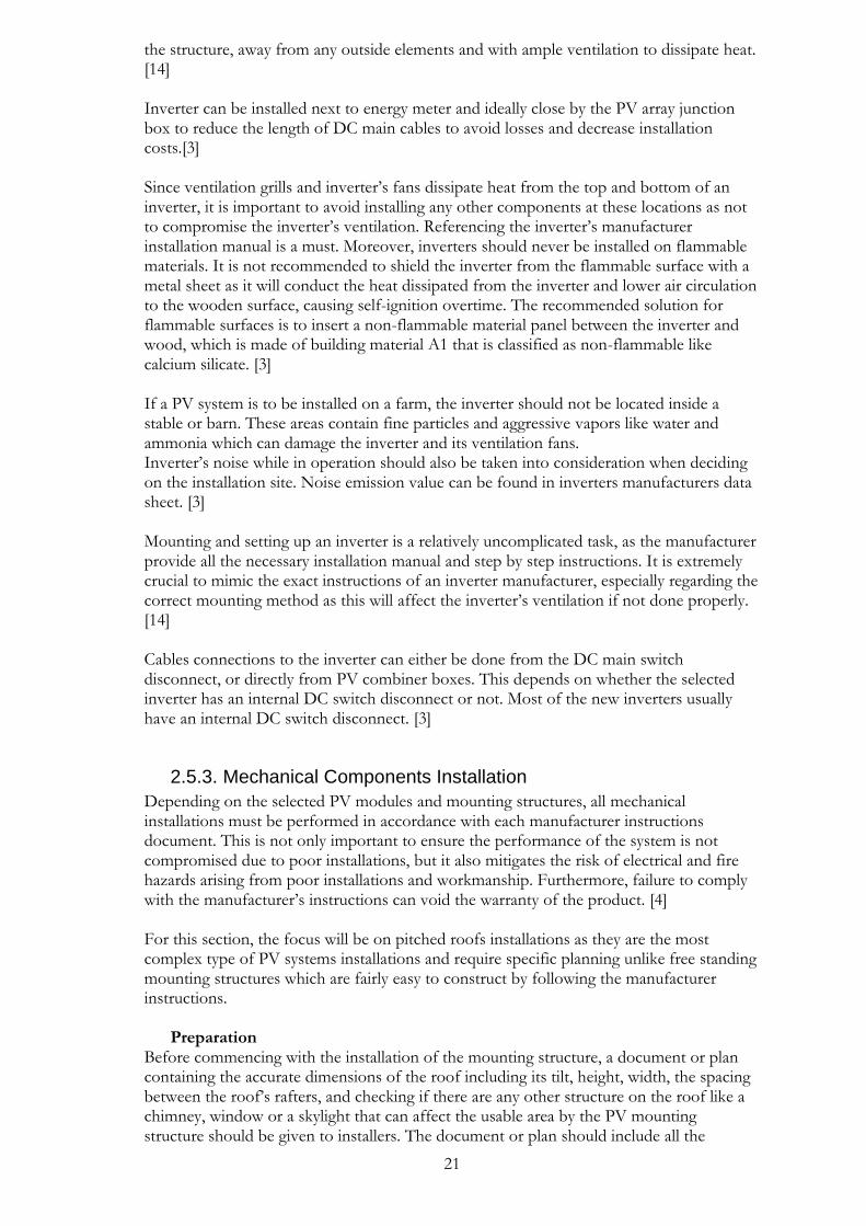
Before starting the installation procedure, the number one priority falls on safety and mitigating electrical hazards as illustrated in Figure 2.4 in a PV installation. Not using the appropriate equipment, working in an unsafe environment and not following the best practices and instructions set by manufacturers of different components, can lead to potential self-injury or impose fire hazard in the workplace. [4] To mitigate any electric hazards during installation, the following gear and best practices should be followed [4] :
• All individuals on the job site should wear non-conductive class E hardhats which are specifically designed to have a dielectric protection up to a maximum of 20,000 V.
• Installers must wear non-conductive foot protection that are electrical hazard rated.
• Installers must wear electrical insulating gloves as they can be exposed to high voltage levels.
• All the needed power tools for the installation should be double insulated, grounded and must have safety switches. Hand-held tools are to be characterized with an on/off switch that requires constant pressure from the user to prevent any accidental operation.
• When working on rooftops, special care is to be taken if there are overhead power lines or other unnoticed electrical conductors.
• Any work performed on electrical components and circuits must be done when the components are de-energized.

19
Figure 2.4 Safety gear and Personal fall arrest system
2.5.2. Electrical Components Installation
PV assembly Assembling PV modules is the first step in the installation process. Installers should always remember when handling PV modules that they are never disconnected as long as they are exposed to solar radiation, thus all the aforementioned safety precautions should be taken into consideration when working with high voltage. There are two pillars associated with the PV assembly phase [14]: Positioning PV modules and balance of system components There are two stages for fixing PV modules to the mounting structure; connecting PV modules in parallel or series configuration, and the physical fixation of the mounting structure itself. No additional holes are to be drilled into the module’s frame. They are specifically designed and stress tested by the manufacturer. [14] PV modules are mounted with their aluminum frame either clamped to the bottom and top of the mounting rails or bolted with fasteners. [4] Handling PV modules with care at all stages of installation is of vital importance. Module edges should not be heavily impacted in any way or the edges dinted or chipped. Extreme care is to be given when handling unframed laminates like thin film modules as they are more susceptible to cracking due to an impact or damage to any of its edges. Small chips in the laminated glass of PV modules can destroy the module as they lead to irreversible cracks. The appropriate mounting clamps and the correct value of torque provided by the module’s manufacturer has to be followed. [4] The installer should reduce the length of cables as short as possible to minimize system losses attributed to cables [4]. It is crucial that the DC+ and DC- wires of each string be tied together as close as possible with no more than 2 cm separation distance to ensure minimal electromagnetic interference. If excess wire is present, it shouldn’t be coiled. Moreover, conduits, metal raceways or other means of combining strings wires together should be used. It is very important to note that there should be at least 50 cm distance between wires from separate strings connected to another inverter. All the cable ties used to bundle wires together must
20
have a lifetime as the installed system, greater or be replaced during scheduled maintenance. [17] The location of module junction boxes and cable routes are important to be well organized and optimally placed during installation. Junction boxes should not be installed at locations where they hinder easy access to PV modules for inspection or maintenance. [4] This does not only apply to junction boxes, but to all Balance of System (BOS) components. They all should be installed in a way that allows for easy access for inspection, maintenance and disconnecting the components when needed. If the PV installation is on a residential roof, it is recommended to install the combiner box that can include all the necessary circuit breakers and disconnect switches, fuses, monitoring equipment and remote rapid shutdown if included in a more accessible position inside the structure. PV modules usually have warranties that extend from (20-25) years. The same may not apply to other BOS components installed on the roof, so, it is crucial to plan the location of each component appropriately taking into consideration manufacturer’s recommendations and installation manual. This is especially important for PV systems that operate at 48 V or less. All DC cables should be minimized in this case as 48 V systems usually have higher current values and it is important to use shorter cables with thicker diameters to tolerate the higher amperage values. On the other hand, PV systems that operate at voltages exceeding 300 V, are more flexible and longer DC wiring will not result in any significant voltage drop. [4]
Connecting PV modules After mounting PV modules on mounting structure, the objective now is to prepare the two terminals of each PV module; the positive and negative that are included in the main circuit of the module. It is easy to accidently connect the wrong polarity between two PV modules connectors depending on the type of configuration; either parallel or series connection. That is why it is recommended that installers have an electrical single line diagram or a technical drawing that includes the wiring and position of the PV modules in the installation area. [14] For installations that have mixed connections and many strings in parallel, the cable from each string must be connected to a central fuse or a combiner box and be run in parallel with the other strings. The combiner fuse box will contain all the circuits’ breakers, fuses and any other additional safety components added to the system according to the design specifications. The combiner fuse box is the hub of the PV field that allows for easy access to all PV strings for troubleshooting errors, performing measurements or doing routine maintenance. [14] Wiring and cable routing Wiring a PV system include all the necessary connectors, junction boxes, cables conduits and all other wirings required for and between the BOS components. The most common and recommended type of wiring method for cables leaving the area of PV arrays are conduit systems. Conduits are widely used to protect a string conductors and support the connection between combiner boxes and inverter. There are different types of conduit according to the requirement and application of the system design. [4] For pitched roofs installations, array cables are usually routed through the roof’s structure; inner cladding, to the inverter inside the residential house or building. It is crucial to seal the points of penetration through the cladding to preserve the roof’s water and thermal protection capabilities. [3]
Inverter Installation The location at which an inverter should be installed depends on its specifications in the technical data sheet provided by the manufacturer. If the inverter lacks the appropriate IP rating for water and dust resistance, and if the operating temperature range of the inverter does not suit the PV system location, then it shall be installed in a sheltered place inside
21
the structure, away from any outside elements and with ample ventilation to dissipate heat. [14] Inverter can be installed next to energy meter and ideally close by the PV array junction box to reduce the length of DC main cables to avoid losses and decrease installation costs.[3] Since ventilation grills and inverter’s fans dissipate heat from the top and bottom of an inverter, it is important to avoid installing any other components at these locations as not to compromise the inverter’s ventilation. Referencing the inverter’s manufacturer installation manual is a must. Moreover, inverters should never be installed on flammable materials. It is not recommended to shield the inverter from the flammable surface with a metal sheet as it will conduct the heat dissipated from the inverter and lower air circulation to the wooden surface, causing self-ignition overtime. The recommended solution for flammable surfaces is to insert a non-flammable material panel between the inverter and wood, which is made of building material A1 that is classified as non-flammable like calcium silicate. [3] If a PV system is to be installed on a farm, the inverter should not be located inside a stable or barn. These areas contain fine particles and aggressive vapors like water and ammonia which can damage the inverter and its ventilation fans. Inverter’s noise while in operation should also be taken into consideration when deciding on the installation site. Noise emission value can be found in inverters manufacturers data sheet. [3] Mounting and setting up an inverter is a relatively uncomplicated task, as the manufacturer provide all the necessary installation manual and step by step instructions. It is extremely crucial to mimic the exact instructions of an inverter manufacturer, especially regarding the correct mounting method as this will affect the inverter’s ventilation if not done properly. [14] Cables connections to the inverter can either be done from the DC main switch disconnect, or directly from PV combiner boxes. This depends on whether the selected inverter has an internal DC switch disconnect or not. Most of the new inverters usually have an internal DC switch disconnect. [3]
2.5.3. Mechanical Components Installation
Depending on the selected PV modules and mounting structures, all mechanical installations must be performed in accordance with each manufacturer instructions document. This is not only important to ensure the performance of the system is not compromised due to poor installations, but it also mitigates the risk of electrical and fire hazards arising from poor installations and workmanship. Furthermore, failure to comply with the manufacturer’s instructions can void the warranty of the product. [4] For this section, the focus will be on pitched roofs installations as they are the most complex type of PV systems installations and require specific planning unlike free standing mounting structures which are fairly easy to construct by following the manufacturer instructions.
Preparation Before commencing with the installation of the mounting structure, a document or plan containing the accurate dimensions of the roof including its tilt, height, width, the spacing between the roof’s rafters, and checking if there are any other structure on the roof like a chimney, window or a skylight that can affect the usable area by the PV mounting structure should be given to installers. The document or plan should include all the
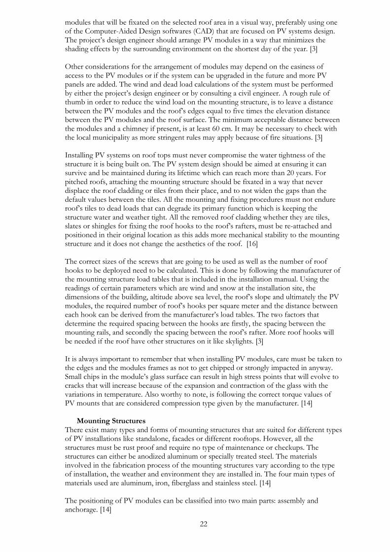
22
modules that will be fixated on the selected roof area in a visual way, preferably using one of the Computer-Aided Design softwares (CAD) that are focused on PV systems design. The project’s design engineer should arrange PV modules in a way that minimizes the shading effects by the surrounding environment on the shortest day of the year. [3] Other considerations for the arrangement of modules may depend on the easiness of access to the PV modules or if the system can be upgraded in the future and more PV panels are added. The wind and dead load calculations of the system must be performed by either the project’s design engineer or by consulting a civil engineer. A rough rule of thumb in order to reduce the wind load on the mounting structure, is to leave a distance between the PV modules and the roof’s edges equal to five times the elevation distance between the PV modules and the roof surface. The minimum acceptable distance between the modules and a chimney if present, is at least 60 cm. It may be necessary to check with the local municipality as more stringent rules may apply because of fire situations. [3] Installing PV systems on roof tops must never compromise the water tightness of the structure it is being built on. The PV system design should be aimed at ensuring it can survive and be maintained during its lifetime which can reach more than 20 years. For pitched roofs, attaching the mounting structure should be fixated in a way that never displace the roof cladding or tiles from their place, and to not widen the gaps than the default values between the tiles. All the mounting and fixing procedures must not endure roof’s tiles to dead loads that can degrade its primary function which is keeping the structure water and weather tight. All the removed roof cladding whether they are tiles, slates or shingles for fixing the roof hooks to the roof’s rafters, must be re-attached and positioned in their original location as this adds more mechanical stability to the mounting structure and it does not change the aesthetics of the roof. [16] The correct sizes of the screws that are going to be used as well as the number of roof hooks to be deployed need to be calculated. This is done by following the manufacturer of the mounting structure load tables that is included in the installation manual. Using the readings of certain parameters which are wind and snow at the installation site, the dimensions of the building, altitude above sea level, the roof’s slope and ultimately the PV modules, the required number of roof’s hooks per square meter and the distance between each hook can be derived from the manufacturer’s load tables. The two factors that determine the required spacing between the hooks are firstly, the spacing between the mounting rails, and secondly the spacing between the roof’s rafter. More roof hooks will be needed if the roof have other structures on it like skylights. [3] It is always important to remember that when installing PV modules, care must be taken to the edges and the modules frames as not to get chipped or strongly impacted in anyway. Small chips in the module’s glass surface can result in high stress points that will evolve to cracks that will increase because of the expansion and contraction of the glass with the variations in temperature. Also worthy to note, is following the correct torque values of PV mounts that are considered compression type given by the manufacturer. [14]
Mounting Structures There exist many types and forms of mounting structures that are suited for different types of PV installations like standalone, facades or different rooftops. However, all the structures must be rust proof and require no type of maintenance or checkups. The structures can either be anodized aluminum or specially treated steel. The materials involved in the fabrication process of the mounting structures vary according to the type of installation, the weather and environment they are installed in. The four main types of materials used are aluminum, iron, fiberglass and stainless steel. [14] The positioning of PV modules can be classified into two main parts: assembly and anchorage. [14]

23
Assembly involves joining all the different parts of the mounting structure like the frame, mast, shape and any other components. On the other hand, Anchorage involves fixating and fastening of the mounting structure to a surface such as roof, ground, façade or any other relevant surface. Anchorage operation is crucial as the main objective is to secure the mounting structure in a way that is necessary to resist the maximum amount of snow and wind speeds at the location. The anchorage process should be well planned before the installation process as it can require some civil construction work depending on the location and the surface the mounting structure is anchored to. [14] In the past, mounting structures installed on roof tiles or slates, were fixated by bolting through the cladding. However, this approach had problems as it allowed the tiles or slates to crack underneath the fixed bolts and sealing washer that prevents water penetration, resulting in a compromise in the roof’ durability and its ability to prevent water leakage inside the structure. [14] If “through bolt” method of mounting structure fixation is to be used on the roof cladding, then the following requirements should be met [14] :
1. The bolt used for the penetration should not transfer any dead load on the tiles or slates underneath it.
2. Silicon or any other mastic (liquid) sealant are not to be used to provide the required water tight seal at the point of penetration.
3. All the points that are perforated by the bolts must be adequately and durably sealed.
4. Sealing washers are not to be used to provide water tight seal as they add more pressure on the tiles or slates as they are firmly pressed down against their surface.
5. The bolts deployed are not to be fixed to the roof’s battens.
Before commencing with the installation process, it is important to inspect the state of the roof at question and whether there are any damages to it. If there is a damage present, it should be repaired or replaced if necessary. Any underlay damage will cause problems inside the structure as it will not be weather tight and can allow water and wind loads inside it as illustrated in Figure 2.5 for a case study before a PV system installation. [14]
Figure 2.5 Rotten wood of a residential house roof structure during inspection
Unless limited by design reasons, the PV system and the mounting structure should be installed away from the edges of the roof. For a residential roof, the minimum clearance distance from a roof’s parameters should be approximately (40-50) cm. There are few main reasons for this including [16] :
• Wind loads around the edges of the roof are higher than the other zones.

24
• Depending on the country’s PV systems regulations, keeping spaces at the edges of the roof facilitates better access to the PV system for inspection, maintenance or for firefighters in case of a fire breakout. In Figure 2.6 there is a clear violation for firefighter’s codes in the US because there is no clearance distance of at least 0.99 m from the roof ridge.
• Installing PV modules close to the edges can interfere with the roof’s rain drainage routes and limit their effectiveness.
Choosing the correct mounting structure for a PV system is crucial, as it has direct effect on the peak and average operating temperatures of the installed PV arrays. Arrays that operate at higher temperatures will experience reduction in output power, array voltage, and the amount of produced energy and will speed up the degradation process of the PV modules over their lifetime. [4] PV arrays that are fixated on free standing mounting structures exhibit the maximum cooling and lowest operating temperature ranges, as their operating temperature increase from ranges of 15 oC - 25 oC above the air ambient temperature at solar irradiance level of 1000 W/m2. On the other hand, PV arrays that are installed on direct mounts, exhibit the highest values of operating temperatures with rise coefficients of 35 oC – 45 oC/kW/m2. [4]. Lastly, standoff mounts exhibit moderate values for operating temperature compared to the other two mounting structures. This is due to the fact that standoff mounts can be adjusted according to the design requirement on how much they can be elevated from the roof’s surface. Generally, maximum gains in passive cooling can be achieved in standoff structures when the PV modules are (7-15) cm above the roof material. [4] Standoff PV arrays are either bolted or clamped to the two parallel mounting rails or beams that provide the essential support needed for the modules. The beams are weather sealed and fastened to the roof’s structure at pre-determined penetration points with special brackets designed for the mounting structure and the type of roof cladding that is being installed on. Depending on the geographical data of the installation site, locations that exhibit higher wind speeds will require stronger rails, or more attachment points between the beams and the building structure in order to avoid unwanted modules and rails deflection from wind loads. The attachment points between the mounting beams and the building must be installed properly as they are the critical points holding the mounting structure in place. [4] Figure 2.6 Violation of fire safety codes in the US
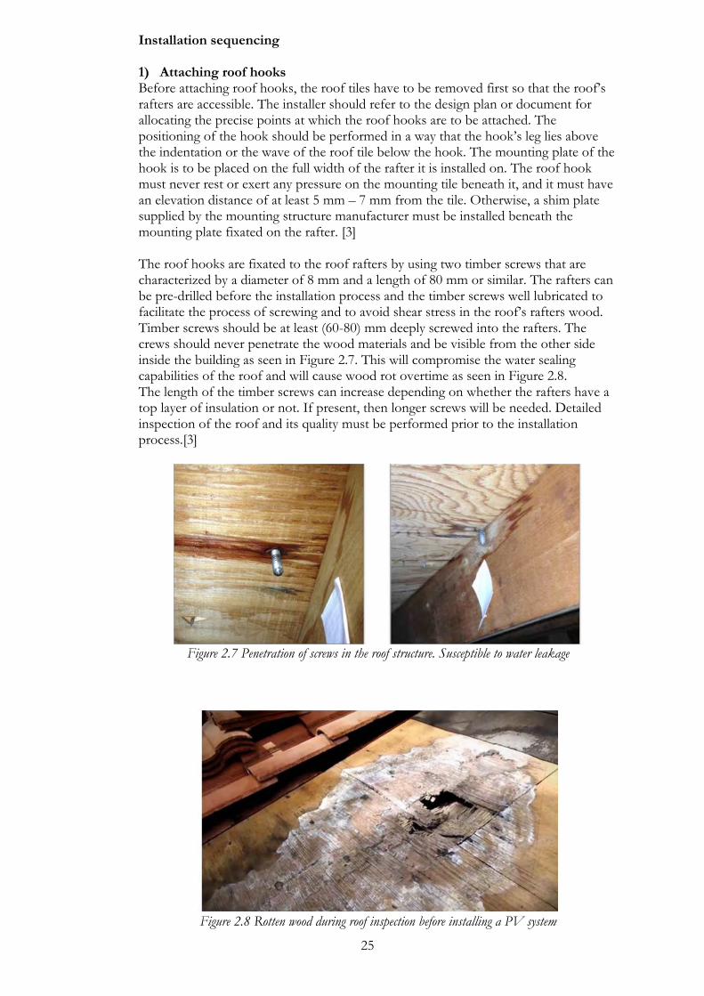
25
Installation sequencing 1) Attaching roof hooks Before attaching roof hooks, the roof tiles have to be removed first so that the roof’s rafters are accessible. The installer should refer to the design plan or document for allocating the precise points at which the roof hooks are to be attached. The positioning of the hook should be performed in a way that the hook’s leg lies above the indentation or the wave of the roof tile below the hook. The mounting plate of the hook is to be placed on the full width of the rafter it is installed on. The roof hook must never rest or exert any pressure on the mounting tile beneath it, and it must have an elevation distance of at least 5 mm – 7 mm from the tile. Otherwise, a shim plate supplied by the mounting structure manufacturer must be installed beneath the mounting plate fixated on the rafter. [3]
The roof hooks are fixated to the roof rafters by using two timber screws that are characterized by a diameter of 8 mm and a length of 80 mm or similar. The rafters can be pre-drilled before the installation process and the timber screws well lubricated to facilitate the process of screwing and to avoid shear stress in the roof’s rafters wood. Timber screws should be at least (60-80) mm deeply screwed into the rafters. The crews should never penetrate the wood materials and be visible from the other side inside the building as seen in Figure 2.7. This will compromise the water sealing capabilities of the roof and will cause wood rot overtime as seen in Figure 2.8. The length of the timber screws can increase depending on whether the rafters have a top layer of insulation or not. If present, then longer screws will be needed. Detailed inspection of the roof and its quality must be performed prior to the installation process.[3]
Figure 2.7 Penetration of screws in the roof structure. Susceptible to water leakage
Figure 2.8 Rotten wood during roof inspection before installing a PV system

26
2) Roof tile cutting It is necessary to make sure that the tiles that were removed for installing the roof hooks are placed back into their original position, lying flush like the other tiles. This can be achieved by cutting or grinding down the tiles to adapt for the extra elevation added by the roof hook. The roof tiles can be positioned again in place and then sealed appropriately against various weather conditions. The installer must ensure that the tiles are flush with no added gaps between them, otherwise the roof’s water tightness will be compromised and water can leak inside the building. The project engineer at site must inspect after the installers to ensure that the tiles positioning and quality remain the same after fixing the roof hooks. All the safety regulations are to be followed, as the installer must wear protective gloves and eye goggles to protect against debris from grinding or cutting down the tiles. [3]
3) Fitting the mounting beams The mounting beams or rails have to be sized to the required design length. This can either be done by the manufacturer of the beams or for more flexibility it can be done on the installation site by the installers by sawing the rails in length before fastening the two parallel beams to the roof hooks. The mounting structure manufacturer should include all the necessary components for fixing the rails. Usually the beams are fixated from underneath them through elongated holes using a nut, a washer and a hexagonal socket screw. It is crucial to ensure that the beams are leveled evenly across the whole length of the PV array. Unevenness in the beams can be rectified by the elongated holes in the beams and the roof hooks and deploying flat washers if needed. Since the mounting beams are installed across the width of the roof, multiple rails will need to be connected together as seen in Figure 2.9. This can be done by connecting them together but leaving a small gap between each beam to allow for linear expansion using screwed flat connectors. After all the rails are aligned, all the screwed fasteners are tightened according to the torque value specified by the manufacturer using a torque wrench. [3]
Figure 2.9 Mounting rails for PV systems on pitched roofs
4) Mounting PV modules PV modules can be mounted on the beams by either bolting them with fasteners or clamping them to the top and bottom beam [4]. Bolts are secured in the mounting holes located on a PV module’s frame with its shaft facing outwards and securing it with nuts. The external threaded part of the bolt that is projected from the back of the module’s frame will be used to connect or hang the module to the upper mounting beam on the roof. Before PV modules are firmly bolted, they have to be electrically connected together by connecting each module’s plug connectors to the neighboring module connectors. The

27
best way to secure the cables is to place them in the groove in the transverse rails and tying them to the rails using UV resistant cable ties. This is important to ensure that there are no blockage for rainwater when they are slipping down the roof to the drainage pipe and that no water can enter into the plug connectors. It also ensures that there will be no snow build up underneath the modules as a result of long loose cables. Depending on the roof design, it is usually more convenient to mount PV strings or rows from the top of the roof first to the bottom. [3]
5) Routing string cables All string cables will have to be protected inside conduits running through the roof’s inner cladding at pre-drilled points from the roof outer surface. It is extremely crucial to make sure that the entry points for conduits in the inner cladding is sealed appropriately to ensure its water and thermal capabilities remain intact. [3] Conduits are inserted through the pre-drilled openings and fixed to prevent them from moving or sliding out of place. The string cables are then pulled inside the conduits or they can be inserted inside the conduits from the start before inserting the conduits in the holes. It is a good practice to insert the conduits at points where there is an overlap between two vapour barrier sheets of the roof to make it easier to seal the entry points. All the used conduits must be rated as UV resistant and able to be deployed in an external environment. [3] The last step is to route the string cables through an opening of a ventilation tile. The cables are inserted through the opening in the tile and it ensures that the roof cladding is still weather tight at this entry point. The tiles used for this purpose are usually chosen to be below PV modules, so it does not alter the roof’s aesthetics. All the string cables are attached to the mounting frame usually by zip ties to the selected first and last modules in the array. [3]
2.5.4. Water Tightness
A thorough roof inspection should be performed by a qualified roofer or inspector to check for the state and condition of the roof and its weather sealing properties during the design phase of a PV system installation. In most cases, the roof will require minimal repair and restoration work to extend its life time and ensure no water leakage will occur. Any damage to a roof’s insulation that is ignored before PV installation, can lead to serious structural damage to the property after system installation due to its added weight and placement on the insulation material. [18] In addition to roof’s waterproof check, thermal resistance must be inspected and if necessary, an assessment should be carried out as to whether a new insulation is needed or not. This is also applicable in the case that the insulation is saturated or waterlogged which indicates that the covering is not effectively watertight. If there are affected localized and limited areas, then restoration work may prove sufficient by replacing the area with a new dry insulation without the need to replace the whole insulation on the roof. [19] General qualities that characterizes a waterproof insulation in a good and acceptable conditions are : [19]
• Complete dryness and water tightness
• No folds and free from very visible undulations
• No folds at areas where two insulating covers are joined together
• No creases that can extend to the whole surface of the covering
• It should be no older than 15 years

28
Special considerations should be directed to roof membranes with existing penetrations. PV panels especially rack mounted systems can be mounted over or around the penetrations. A minimum of (20-30) cm of added flashing height is recommended for such instances. The quality and integrity of the work performed should be inspected by a qualified roofer to ensure it complies with the roof‘s manufacturer warranty. [18] The lifetime and age of the roof is an important aspect that should be investigated before a PV system installation. If an assessment is made and the roof is found to be in need of replacement in less than five years, it may prove to be economical to replace the roof insulation material as opposed to re-roofing after the PV system is installed. In some installations, PV systems can add to the lifetime of the roof if they fully cover the roof, as they insulate the membrane from UV exposures and high temperatures; which are the two main causes of roof deterioration. [18] Some roofs like spray-foam roofing have to be assessed more carefully than others, as coatings may need to be re-applied more frequently with elastomeric coatings. The PV system should be designed in such a way that it will not hinder the roof’s accessibility when needed. PV systems installed on large roofs that may see heavy foot traffic for educational or other purposes, may need a temporary or a more permanent measure to protect the roof. [18] Some roof types may not be compatible with PV ballast mounting systems. Single-ply, mechanically attached roof membranes that do not have sufficient air barrier, are prone to swelling or billowing because of the added weight to the roof. If the possibility of roof billowing is suspected before the system’s installation, a consultation from roofing manufacturer is necessary to assess if it will prove to be a problem. In most cases, PV ballasted systems do not have enough weight to remain in their original location if the roof membrane billows. [18] Roof underlayment Properly installed roof tiles can last many decades; ranging from 50-75 years and they dissipate heat more effectively than asphalt shingle roofs. That is why in the southern regions of some countries like the US, tile roofs are dominant in-home installations for the last three decades. On the other hand, roof underlayments that protect a roof’s structure from water penetration, can last as little as 15 years. The most commonly used underlayments are synthetic polypropylene, modified bitumen membrane or asphalt felt paper. The majority of roof underlayments are made of asphalt-impregnated felt paper. The downside is that felt paper decomposes at high rate when exposed to excessive UV, moisture and heat. [20] Synthetic or plastic underlayment are also two other options that roofers recommend for homeowners. Their lifetime can last between 30 - 50 years and they do not decompose when exposed to long periods of water moisture. Moreover, they weigh less on the structure, offer high fire resistance and they can be bent as required around corners without any tearing like a normal underlayment felt. [20] Replacing a roof’s underlayment after a PV system is installed is a major and expensive task that requires the removal of all PV panels, mounting racking system, wires, battens and all the roof’s tiles. The cost of removing and reinstalling a PV system on a tile roof can reach up to 20 % - 30 % of the cost of purchasing a new PV system. The average tile roof requires an underlayment replacement every 15-25 years as seen in Figure 2.10, and so it is encouraged that PV installers advise residential homeowners to replace roof battens and underlayment before installing a PV system.[20]

29
Figure 2.10 Deteriorated underlayment during inspection before PV system installation in Arizona, US.
It lasted only 16 years. Standoffs and double flashing Standoffs which are comprised of an aluminum base and an elevated post, are the most commonly used mounting means of securing rails on a tile roof in the US as they comply with all applicable roof codes and waterproofing. Standoffs can be installed on any type of tile roof and they usually stand 10 cm -20 cm when attached to rafters of a pitched roof as illustrated in Figure 2.11. They come with double flashing system for water sealing and can be used with any mounting racking system.[20]
Figure 2.11 Adding an underlayment sheet after fixing a standoff
Standoffs and double flashing systems in general requires more labor dedicated to cutting a small hole in the tile which can be challenging if the appropriate tools like diamond blades on angle grinders are not available. Standoffs are stronger than roof hooks and better at waterproofing the roof if inadequate sealant is used with roof hooks. [20]

30
The hole made in the tile by the standoff must be flashed at the penetration point to provide ample waterproofing. Nowadays, the common material chosen for the flashing is dead soft aluminum. They work on all tile roofs, nontoxic and recyclable, and can last for decades. The standoffs base must be sealed with an underlayment bibbing. [20]
Figure 2.12 Standoffs final appearance on pitched roof
Tile hooks Tile hooks have few advantages when compared to standoffs, as they are less expensive, faster and easier to install, and they are more ascetically pleasing with no flashing visible underneath the tiles. [20] Tile hooks are passed between two tiles when installed correctly and they do not penetrate or touch the surface of the tile above them. Removing the tile’s weather guard lug from its bottom surface is a must when installing roof hooks. This can be achieved by a tuck pointing diamond blade used on an electric grinder as present in Figure 2.13. [20]
Figure 2.13 Grinder with a diamond blade to grind roof tiles
Tile level flashing is not required in the case of roof hooks as opposed to standoffs. However, it is mandatory to install base flashing at the underlayment level at every roof hook penetration. This is needed to protect roof hooks’ fasteners from water penetrating them when present on the underlayment membrane. [20] Approved roof sealants that are compatible with roofing materials and membranes are to be used. Poorly chosen sealant will deteriorate over time and will compromise the integrity of the roof. After drilling the hook’s roof holes into rafters (see Figure 2.14), fill them with sealant using a caulking gun as in Figure 2.15 and then attach the hook and its base plate with timbre screws as shown in Figure 2.16. [21]

31
Figure 2.14 Drilling holes in underlayment
Figure 2.15 Filling drilled holes with Figure 2.16 Fixing roof hooks a roof sealant by a caulking gun
2.5.5. Signs and Labels
Labelling of PV systems is a must not only to facilitate the process of inspection and maintenance or adding future upgrades to the system, but more importantly for safety reasons to the individuals in the vicinity of the system or for firefighters during fire outbreaks. All the necessary signs and labels must be visible, easily identified and fixated to last as long as the PV system’s lifetime. [16]
1) DC switch isolator: A label must be fixated on the DC switch isolator and it must be clearly labelled as ‘PV array DC isolator’. The ON/OFF switch or lever labelling must be clearly visible and marked. Moreover, a ‘Danger- contains live parts during daylight’ is to be fixated on the dc switch isolator’s outer enclosure.
2) Plug and Socket connectors: A sign reading ‘Do not disconnect dc plugs and sockets under load-turn off ac supply first’ must be fixed next to all visible connectors that can be accessed by anyone on site. All other connectors that are hidden and can only be accessed by trained personnel in the events of inspections or maintenance can be exempted from labelling.
32
3) DC junction or combiner box: There are two labels that must be present on the junction box. ‘PV array DC junction box’ and ‘Danger. Contains live parts during daylight’.
4) Inverters: While not mandatory and crucial as the other labels, it is recommended that the inverter is labeled with a sign ‘Isolate AC and DC before carrying out work’ for certified electricians or personnel who have to work on the inverter during maintenance.
5) AC switch isolator: It must be labeled with a clear and visible sign ‘PV system-main AC isolator’.
6) Dual supply: A dual supply warning sign is to be fixated at the meter location, service termination and any other joints or isolation points. The sign is to indicate that there is a generation on site and to indicate the position of the main ac switch isolator. The label should read ‘Do not work on this equipment until it is isolated from both mains and on-site generation supplies’. Both the locations of the on-site generator and ac mains supply have to be indicated on the label.
System commissioning
After the electrical and mechanical installation of a PV system are conducted, the system has to be visually inspected, tested and commissioned to verify that the installation matches the applicable codes, the system’s design plan and that the performance is achieved as expected with no operation problems. [4] The system design engineer or constructer must issue a certificate of commissioning. The certificate details all the important technical information of the installed PV system with a log containing the various electrical measurements taken after the installation process. [3] Commissioning of PV systems is initiated immediately after the installation is completed, and before the system is booted on for the first time. Few of the required tests during commissioning maybe repeated again at various stages of the PV system’s lifetime during inspection and maintenance. [4] The visual inspection and system testing documentation is usually comprised of three additional forms. Firstly, an installation certificate that includes a listing of the tested components and items, and a system test result schedule. Secondly, a form for the visual inspection and testing of DC circuitry especially the various PV arrays. Last but not least, an appendix that includes all the inspection and testing of the various PV array circuits and its documentation. [14] The various important aspects of a PV system commissioning include but not limited to [4]:
• Completing all the remaining final installations.
• Visual inspection and a complete system checkout.
• Verifying wiring, all the joint points and connectors workmanship and ensuring that all torques values for the mechanical structures are according to the manufacturer’s recommended values.
• Completing all the necessary signs and labels requirements and system documentation.
• Initialize first system startup.
• Test and verify the various shutdown procedures.
• Verify the system performance and expected output as per design.
• Compiling and finalizing all system documentation including but not limited to permits, warranties, manuals and financial invoices.
• Conduct an orientation session for the PV system user.
33
Before initializing the first system startup, a punch list including the completed items should be included. The list should contain [4] :
• Verify that the various system switch disconnects are open, all the fuses are removed and the lockout procedures are in the correct locations.
• Visual inspection for all the mechanical and electrical components to ensure installation integrity.
• Verify terminal torque specifications and ensure that there are no compromises in the various wires insulations and connections.
• Verify that all equipment and components labels are in place in the correct locations.
• Verify that the installation matches the initial system design and that it follows the applicable codes and regulations requirements.
• Identify, track and resolve any remaining item in the system.
2.6.1. System documentation
Regardless of the type of the PV system installation, every PV system must have ample documentation providing extensive details of the initial and final system design, equipment and components used, and all the deployed construction and civil materials. The system document should include a well elaborated section for the end user, detailing safety information and the proper procedures to follow for operation and maintenance of the system. [22] For safety and reliable operation of the installed PV system, the following are some reasons for the need of a PV system documentation [22]:
• For permits and plan review by the local municipality officials.
• To get an approval from the local utility regarding the extra needed interconnections between the PV system and grid.
• To supply installation and maintenance contractors with a copy.
• To inform the local fire emergency services of the planned installation of a PV system.
• For end users and owners of the system for various reasons including insurance and operation purposes.
A PV system documentation including but not limited to testing land maintenance logs, is a record that exist as long as the constructed system is operational. The documentation which is handed out to the customer after commissioning should include all the following [22] :
• The DC and AC power ratings of the system. This include: Each component manufacturer, model and number of PV modules, inverters and any other BOS and major system components. The dates associated with the final system installation, inspection and commissioning are to be logged as well.
• All the relevant contact information for the system’s owner, system design engineer, Installation Company and any other involved parties in the system installation, are to be written in the document.
• An illustration or a complete system layout plan with BOS components locations on the building or installation area is to be included. Some owners may request the expected performance and power output, and shading analysis in the final documents.
• A single line diagram showing the system design including the modules, configuration and number of modules per string and number of arrays, number of inverters and any other major component. For large PV systems installations, a

34
detailed single line electrical and mechanical diagram is a must and required by the project owner.
• Specific details of all BOS components including ratings and sizes are to be included in the single line diagram. In addition, raceways, junction boxes and source circuit combiner boxes, earthing equipment and any other applicable components are to be annotated on the diagram.
• Information representing operation and maintenance procedures, emergency shutdown and firefighter’s switch if present, are all to be included for the system’s owner. A guideline regarding the required periodical maintenance of components and the PV module cleaning depending on the environment and safety information for owners or professional service if required if the system is complex, are all to be included in the system documentation.
• All the applicable warranties associated with the various components are to be included. The terms of warranties and how the owner can claim it in the event of failure, should be well documented.
• All test reports and data logs for commissioning.
• Financial details and a copy of the contract between the owner and installation company are an integral part of the document. All the relevant invoices for components, labor, permits, and inspection certificates, agreements with the utility grid, tax forms and any other financial and collaborative documents are to be included.
• User manual and instructions for the software used to monitor the system and its performance to the end user.
2.6.2. Visual Inspection
This is an integral part of a PV system commissioning and it should be performed on regular basis over the system’s lifetime. PV systems have to be inspected to ensure that they comply with the various national electric codes regulations and requirements. This include but not limited to [4] :
• Verify the different signs and labels of all equipment and components, making sure they are optimal for the environment and conditions of use and that their installation condition matches each manufacturer instructions.
• Verify the correct ratings and sizing of the BOS equipment.
• Verify proper earthing if applicable.
• Verify that the overall installation is completed in an ethical, workmanlike manner without deviating from any relevant and applicable codes.
2.6.3. Testing the system
Qualified personnel with basic knowledge of the various measurements involved in an electrical system, equipment deployed for the testing purpose and the specifications of the PV system components to be tested should carry out the electrical system testing. The following electrical measurements must be performed before switching on the PV system [23]:
• Test DC circuitry to ensure that it is of correct polarity. Special attention is to be allocated to this test before completing the connection to the inverter as reverse polarity may damage it.
• Test the open circuit voltage (𝑉𝑜𝑐) of PV string. This is carried out to ensure that
the series PV strings are optimally wired. The 𝑉𝑜𝑐 difference between the strings should not exceed 5 % between each other and it should be referenced back to the modules manufacturer permitted tolerances.
35
• Test the short circuit current (𝐼𝑠𝑐) of PV string. This is carried out to ensure that short circuit currents of all the involved PV strings are approximately within 5 % of each other.
• Test the open circuit voltage (𝑉𝑜𝑐) of PV module [3]
• Test earth resistance of the earthing system [3]
• Test isolation resistance of PV module [3]
• Test isolation resistance of DC main cable [3]
Polarity Testing This test must be performed for any type of PV system while commissioning as the polarity of string wiring is a critical point in PV installations. The polarity of the DC side including every source circuit and all of the PV power source must be checked before connecting the strings to one of the DC utilization equipment like inverters, electrical loads, charge controllers or batteries. The outcome of reverse polarity can be significant and hazardous as it can damage PV modules, source circuit wiring or damage a battery permanently in off-grid systems. Some of the available inverters include rectifiers in their circuit topology at the DC input to protect it against reverse polarity wiring. However, many inverters don’t have rectifiers due to added design complexity and cost reasons, in which case, the inverter can be irreversibly damaged due to reversed polarity. [22] PV modules that have bypass diodes, a reversed polarity connection within a series source circuit will force the PV module to operate at reverse voltage. The reversed voltage will be confined and limited by the voltage drop across the bypass diodes which are valued at 0.7 V per diode. Bypass diodes act as barriers to prevent PV modules from operating at high values of reversed voltage. This will have a significant negative effect on the PV string as the current from the other modules in the string that are in series, will bypass the reversed module and the resultant output voltage of the entire string will be reduced by the voltage value of the reversed module plus the voltage drop across the diodes. [22] If one PV circuit source has reverse polarity inside the strings combiner or junction box, it will nullify the output current from other strings that are parallel connected with the correct polarity. This is a challenging problem in large PV installations as many combiner boxes within the array will be installed, and keeping track of polarity of each circuit can be hard. That is why it is crucial that all PV circuit conductors are properly and adequately grouped, labelled and color coded at every termination and connection joints. If a reverse polarity connection is identified during commissioning, the circuit fuses and module bypass diodes must be examined by the engineer at site to check for any damage or replacement if deemed a necessity. [22] Polarity verification can be done by measuring the voltage value of energized circuits before closing the dc switch disconnect and switching ON the system for the first time. A common digital multimeter will satisfy this test. Analog voltmeters are not suitable for this test as reverse polarity can damage their meter’s needle movement. If the polarity is correct, then the sign beside the voltage value on the multimeter will be positive (+). If it is reversed, then the sign will be negative (-) on the display. [22] The polarity test is to be performed on the following components [22]:
• PV modules
• PV source circuits
• PV output circuits
• DC disconnect switches
• Input terminations of the inverter
• Electrical loads
• Charge controller circuits and batteries in case of off-grid systems

36
Insulation Resistance testing Insulation resistance tests are conducted to verify the integrity of the PV system and components wiring. The test will show the level of degradation to the wires insulation and pinpoint errors within PV strings and different system circuitry. This is another crucial test in PV systems commissioning as many PV systems failures and fire hazards arise from bad wiring connections or insulations which increase the risk of electric arcs or shock hazards. [22] Electrical conductors are characterized by an outer insulation layer with very high resistance values that envelops the conductor to protect personnel or other conductors from direct contact. If conductors are exposed at joint or termination points, the air gaps and spacing are the one providing the insulation characteristics. Depending on the resistance value measured, one can determine if the insulation is compromised or not. The test can be done by supplying a constant value of test voltage to a conductor and recording the current flow value between the conductor and earth or between the conductor and other de-energized conductors in the system. The higher the value of resistance recorded, the better the insulation material around the conductor. If there is a degradation in the insulation quality, excessive amount of leakage current will be recorded which can introduce hazards potentials in the system such as shock, equipment damage and low system performance. [22] Wires degradation in PV systems increase over the years due to weather conditions, surrounding environments, animals chewing on cables, or degradation due to high temperatures and excessive exposure to sunlight. It is recommended that insulation resistance tests are carried out every 3 years during inspection and maintenance period, or more frequently depending on surrounding environment and system condition. [22] Insulation resistance test and current leakage are used to test for the integrity of these components [22]:
• To validate the integrity of array source, PV modules and output circuit conductors.
• To measure the leakage current values through protection and disconnect components which include switches, fuses and circuit breakers.
• To measure the insulation resistance of any component with windings. Installers or technicians performing system commissioning must follow these safety precautions prior to testing [22]:
• All personnel conducting the test must wear insulated rubber gloves with leather protectors during the full duration of the test. Unauthorized individuals with no protection gear are to be prohibited from the vicinity of the PV system until the test is conducted.
• The circuits appointed for testing must be disconnected by opening disconnect switches and making sure that the circuits are in de-energized state. The exception to this are PV DC circuits as they are always energized in the presence of light.
• The test lead from the megohmmeter must always be connected first and the last one to break from the circuit after recording the values.
• The insulation resistance test must never be conducted on circuits that have electronic equipment such as inverter, charge controller or surge suppression equipment. These components are designed to operate at a particular voltage range and any high test voltages can irreversibly damage the component.
• Insulation test is never to be conducted on energy storage systems or more specifically batteries.
• Ensure that the circuit under test is properly discharged before and after the insulation test. This can be done through the test equipment or by an external load resistor.
37
Another set of measurements have to be taken after the PV system is switched on which should be logged in a document as well [3] :
• Measure the operating current value of the various PV strings
• Measure the voltage drop across each diode if the system have string diodes
• Measure voltage drop across string fuses if the system contains them Test Equipment The most common equipment used for the insulation resistance test is a megohmmeter. It is a special kind of ohmmeter that has the ability to measure high resistance values by applying high levels of test voltages between the conductors and recording the leakage current. It can be powered by batteries, external power source or by a hand crank. The common voltage range is between 50 V up to 5000 V. [22] Insulation multimeter that are handheld often include voltage, resistance and continuity measurements capabilities. There are others that are specifically optimized for PV arrays testing.[22] Testing considerations Insulation resistance is inversely proportional to the volume of insulation material used for electrical conductors. More insulation volume will have less insulation resistance than a conductor with less. It is also important to note that over time, insulation quality degrades and it is affected by both moisture and temperature. Insulation resistance is inversely proportional to temperature. A 10 oC decrease in temperature will double the insulation resistance. If a conductor have an insulation resistance value of 4 MΩ at 20 oC, this value will decrease to 1 MΩ at 40 oC. Thus, when carrying out insulation resistance test, it should be done at constant temperature values, and avoid doing the test in moisture or condensed conditions. It should be carried out at conductor temperature value above the dew point. [22] Test Procedure The circuits under test must be isolated from any other circuits and be properly discharged before and after the measurements. Any grounding should remain as is. It is worth noting that some coated metal components may need grinding because the test leads must be properly connected. [22] The value of the test voltage is usually higher than the circuits under test operating voltages, but less than the voltage rating of the conductor or equipment. The recommended test voltage for PV strings with a maximum voltage that does not exceed 120 V is 250 V and a test voltage value of 1000 V for PV strings that exceed 500 V. [22] Insulation resistance test is usually performed at source circuit junction boxes where each string circuit can be measured individually. There are two ways to perform the insulation resistance test [22]:
1. Between the negative DC conductor and ground, followed by a test between the positive DC conductor and ground.
2. By shorting DC conductors and ground with a shorting device that have the same voltage and current rating of the circuit. The insulation resistance value can then be taken between the shorted positive and negative conductors array conductors and earth.
If the PV system is not bonded to ground as is the case with most PV systems in Europe, the insulation resistance test will be performed between ground and array cables, and between frame and array cables. In case of installations that deploy conductive parts that are not accessible like PV roof tiles, the insulation test will be carried between the frame and array cables. [14]
38
The following are the steps necessary to perform insulation resistance test [14] :
1. All the PV system’s arrays on the field are to be tested. If necessary, the test can be performed to test individual strings.
2. Personnel performing the test must wear rubber gloves, safety shoes and goggles. 3. If the test is conducted between ground and array’s positive and negative cables,
the cables are to be short circuited with an appropriately rated short circuit junction box.
4. Connect a lead from the insulations resistance test device (megohmmeter) to the PV array cables.
5. Connect the second lead from the megohmmeter to ground. 6. The leads are to be softened and secured with cable ties. 7. Read and follow the insulation resistance test device instructions to ensure taking
the correct voltage values at each array voltage range. 8. Take the readings and double check that the PV system is de-energized before
removing the test cable and touching any parts that are conductive.
According to the standard IEC 62446 in the US NEC, the recommended insulation resistance value for PV systems less than 120 V should be at minimum 0.5 MΩ. For PV systems exceeding 120 V, values equal to or greater than 1 MΩ are acceptable. All the values that are recorded during commissioning should be well documented as they can be used as a reference for future insulation resistance tests over the years to evaluate the degradation levels of the wires. [22] Open circuit voltage testing
The 𝑉𝑜𝑐 of each PV string source circuit must be tested before closing the PV strings DC disconnects, and it should be compared with the expected design values [22]. The open circuit voltage test can only be conducted before the strings in the system are combined
together in parallel configuration [24]. The 𝑉𝑂𝐶 of each string must be measured individually [24]. Moreover, this test can be carried out to check for the correct polarity [22]. It is useful to remember that all the commissioning tests are not carried out to test the system’s performance, on the contrary, they are deployed to verify the integrity and
correctness of the installation process [22]. The 𝑉𝑂𝐶 test requires a voltmeter than can read both DC and AC voltages ranging from (600-1000) V [22].
PV systems that are comprised of small string inverters, the 𝑉𝑜𝑐 will often be measured on the line side of the DC switch isolator while the DC switch is in open position. For PV
systems that contain large number of strings and larger capacity inverters, the 𝑉𝑜𝑐 of each string will often be measured on the line side of fuse holders in the junction or combiner boxes while all the fuses removed. The moment the fuses are connected or the DC disconnect switch isolator is closed, all the strings in the system will be parallel; measuring
the same 𝑉𝑜𝑐 value which invalidates the test. [24] The majority of PV systems that deploy more than one string, usually have the same
number of PV modules connected in series configuration. Thus, 𝑉𝑜𝑐 readings of the strings
are expected to be the roughly the same, or within 5 % of each other. If the 𝑉𝑜𝑐 reading is less than expected, then this can be attributed to wrong array wiring (modules configuration), failure of a module or some bypass diodes may be shorted. It is also
important to verify that the 𝑉𝑜𝑐 value is within the allowable operating voltage range of the inverter or any other dc component like charge controller in case of off-grid operation. [22]
39
Inverter startup sequence The inverter should be switched on after the successful completion of the system’s visual inspections and conducting the DC open circuit voltage measurement for each string to confirm the correct expected values. Instructions supplied by the manufacturer are to be read and followed carefully for the initial startup of the inverter at hand. Generally, the initiation steps will include: [24]
• Verify all DC and AC connections and wiring.
• Verify the correct value and polarity of DC voltage at the DC switch disconnect terminal.
• Verify ac voltage at the ac switch disconnect terminal.
• AC switch disconnect should be closed.
• Measure and verify the AC voltage at the inverter’s output ac terminals.
• Close all DC switch disconnects.
• Measure and verify the correct value and polarity of DC voltage at the inverter’s DC input terminals.
• Switch the inverter and wait for the internal startup.
• Wait for at least 15 minutes after turning ON the inverter for the power point tracking and internal temperature to stabilize.
Short circuit current testing The short circuit test is carried out after initiating the inverter [24]. Verifying that each string is outputting roughly the same amount of current or at least within 0.1 A of each other, is the condition determining whether the test is successful or not [24]. At this stage, the total output of the inverter is not the objective, and not much attention is to be directed to the inverter’s output [24].
Short circuit current (𝐼𝑠𝑐) test is carried out on PV string source circuits to verify that the readings matches the expected values with no major faults. The test is carried out using a digital multimeter that can measure up to 10 A DC current values. However, the installer will need a suitable shorting device to measure the current value. Disconnect switches and some circuit breakers may have the needed rating of dc voltage and current load break, required to short the array source circuits. [22]
𝐼𝑠𝑐 is directly proportional to the available solar irradiance on PV arrays. Therefore, the test must be performed swiftly in the appropriate clear sky conditions. It is important to check that the array is not soiled or partially shaded. The Isc of each string should not deviate from 5 % of each other to be acceptable. [22] Measure AC power output After performing the short circuit current tests and ensuring that the values of current in all the strings are as expected, verifying the inverter’s AC power output is the next step. There are two measurement devices used for the test. A clamp meter to measure current value, and a multimeter to measure voltage. The values of current and voltage displayed on the inverter’s screen should match the current and voltage values of the measuring devices. All the measured and reference values are to be logged in the commissioning document. [24] To ensure the accuracy of the measurement values, all the modules in the PV array must be positioned in the same orientation with no shading effects. It is recommended to perform the power output measurements close to solar noon with solar radiation levels starting from 800 W/m2 or higher with minimal clouds. Moreover, the inverter must operate at the maximum power point (MPPT) for the string under measurement, and the inverter is not to exceed its own voltage limits. [24]

40
2.6.4. Maintenance of PV systems
To ensure reliable and safe operation of PV systems, periodic maintenance should be performed; ensuring the optimal system performance and output. Deviations and system discrepancies identified through inspection and maintenance, have to be rectified through troubleshooting errors to ensure integrity of the system. The frequency and scope of maintenance will be decided by the system size, type, location and performance or lack thereof the system. A maintenance plan usually includes the following [24] :
• Inspect the various system components and wiring techniques.
• Evaluate the integrity of mechanical structures and weather sealing in case of roof installations.
• Removing dust and debris accumulated on PV arrays.
• Performing various electrical tests to analyze system performance.
• Repair or replace damaged components.
• Inspect modules for hotspot areas by using thermal drones to record areas inside modules that exhibit high temperatures.
Visual inspection of the complete system including all components and wiring, is an essential part of maintenance procedures. This task will be the same as visual inspection done during commissioning, but the difference is compliance of the installed system with the various applicable codes will not be evaluated. Rather, the integrity, degradation and physical damage of the system over time. [24] Visual inspections during maintenance include [24] :
• Inspection of PV modules to determine if there any broken or chipped glass, and bent frames. If a module is fractured, the compromised laminates will allow moisture inside the module which will cause faults and leakage current. It must be replaced and removed from the array.
• Inspect for any discolorations or corrosion inside module laminates. This maybe a sign for a hot spot which will degrade the internal cell connections and will eventually lead to module failure or even a fire hazard.
• Remove any falling leaves or debris accumulated on PV modules during maintenance. They not only can cause fire hazards, but they can also degrade wiring systems or block drainage pathway in case of roof based installations.
• Regular cleaning of PV modules especially in arid regions is essential, as output losses by the modules can be reduced by 10 % to 20 % or more.
• Inspect the surrounding environment and scenery and assess if there are any added elements that may have increased array shadings. If visual inspection is not sufficient to evaluate the extent of shading, a complete and detailed shading evaluation and control are to be conducted. Any growing trees or vegetation near PV arrays may require trimming if they shade any module in the array.
• Inspect for weather sealing and structural integrity and security. Perform all the necessary repairs as required according to the extent of damage.
The electrical tests conducted during maintenance, include the majority of tests carried out during PV systems commissioning. This include, open voltage, short circuit, insulation resistance and continuity testing. Testing the system’s polarity can be omitted and is usually not included unless there are signs in the system that links the identified problem with reversed polarity situation. [24] Maintenance tests are first and foremost performed to verify the conformity of certain measurements and verify their degradation rate. For instance, in most PV arrays, voltage and power outputs are predicted to degrade between 0.5 % and 1 % per year. This is

41
consistent with components manufacturer’s data sheets and warranties. Important to note that extra soiling and shading effects are expected to affect these values accordingly. [24]
Troubleshooting Errors Scheme
The majority of PV systems failures occur due to bad practices, or errors done during installation process. This can be mitigated by following all applicable codes, best practices and following design schematics thoroughly and accurately.[14] Troubleshooting a PV system is not a complex task as there are few major components to troubleshoot; PV modules, arrays, combiner boxes and inverters. A true root mean square; RMS AC/DC clamp meter is necessary for troubleshooting most of the errors. A clamp meter with a flexible current probe, will make troubleshooting errors much easier and time efficient due to the large number of wires and connectors in a PV system that are connected together. This is especially true in combiner boxes where there are large number of wires present inside. [25] Below are some of the most common mistakes that can occur during PV systems installations [14] : PV modules and array configurations
• Modifying an array wiring layout without submitting the changes in the original system’s electrical diagram.
• Changing PV modules type or manufacturer because of supply issues, without consulting the design engineer responsible for the system.
• Wrong specifications especially when sizing PV arrays that they exceed the maximum allowable operating voltage ranges of inverter.
• Under sizing PV strings by connecting low number of modules in series for optimal inverter operation during high summer temperatures.
• Grouping and connecting PV modules without taking into consideration the
maximum power point current 𝐼𝑚𝑝𝑝 value of each module.
• String wires reversed. This is a common mistake when custom jumpers are deployed, or even connecting the same gender of wires at the two ends. This will cause the string to not produce any power and it can cause serious damage to the inverter. The occurrence of such error can be lowered if the wiring is clearly identified and color coded during installation. [26]
• Swapped strings wiring. This is not common, however it happened in some installations. The plus and minus wires of two different strings, are connected to each input. For inverters that accommodate many strings bundled together to be connected to the same inverter, each side of a string found to be connected to a different inverter. This can be avoided during installation by taking the time and patience to clearly label and identify each wire. [26]
• Poor crimping workmanship. Using the wrong tools or method to crimp connectors will cause terminals and open circuits heating, which will eventually lead to burning and melting of connectors. It is very common that the wrong crimping tool is used by installers, However, not following the manufacturer instructions and the recommended crimper, will not only lead to future problems like the aforementioned ones, but will also violate the module’s warranty. [26]
Inverter physical mounting
• Not enough room around the inverter to ensure optimal ventilation. In many cases, the inverter is not installed with ample ventilation around it due to aesthetic reasons; ignoring the ease to access the inverter during maintenance and hindering its performance because of lack of air around it. [26]
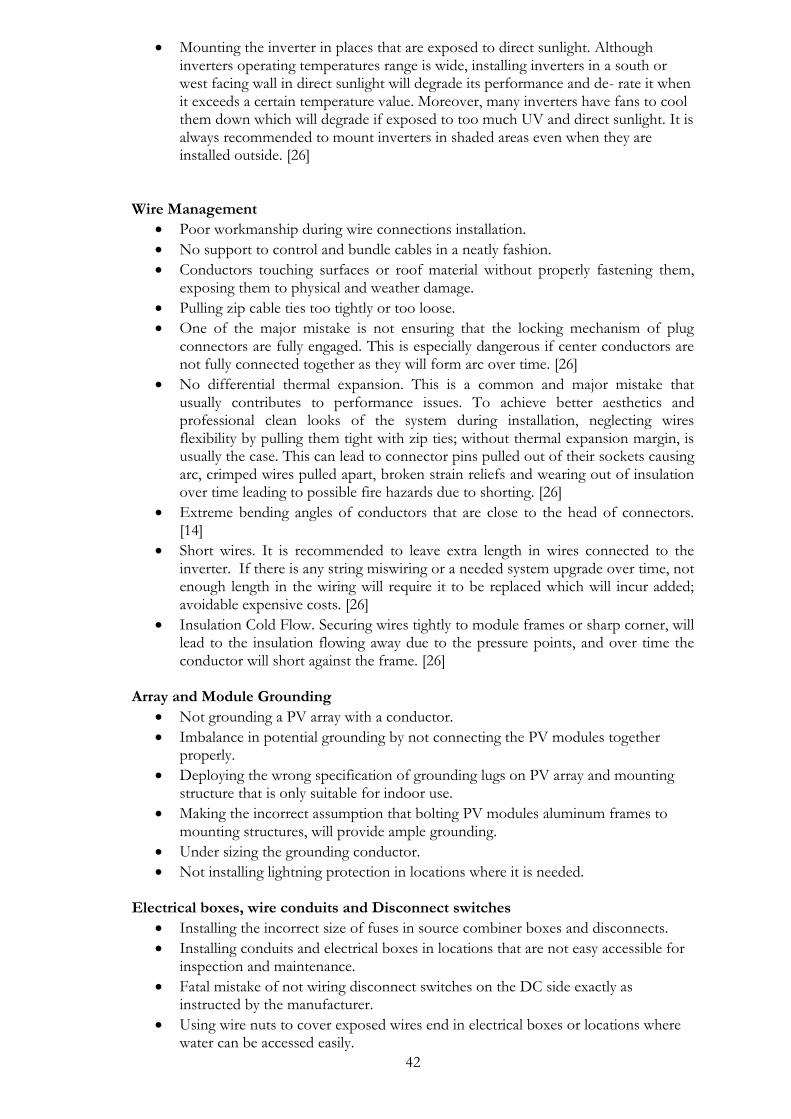
42
• Mounting the inverter in places that are exposed to direct sunlight. Although inverters operating temperatures range is wide, installing inverters in a south or west facing wall in direct sunlight will degrade its performance and de- rate it when it exceeds a certain temperature value. Moreover, many inverters have fans to cool them down which will degrade if exposed to too much UV and direct sunlight. It is always recommended to mount inverters in shaded areas even when they are installed outside. [26]
Wire Management
• Poor workmanship during wire connections installation.
• No support to control and bundle cables in a neatly fashion.
• Conductors touching surfaces or roof material without properly fastening them, exposing them to physical and weather damage.
• Pulling zip cable ties too tightly or too loose.
• One of the major mistake is not ensuring that the locking mechanism of plug connectors are fully engaged. This is especially dangerous if center conductors are not fully connected together as they will form arc over time. [26]
• No differential thermal expansion. This is a common and major mistake that usually contributes to performance issues. To achieve better aesthetics and professional clean looks of the system during installation, neglecting wires flexibility by pulling them tight with zip ties; without thermal expansion margin, is usually the case. This can lead to connector pins pulled out of their sockets causing arc, crimped wires pulled apart, broken strain reliefs and wearing out of insulation over time leading to possible fire hazards due to shorting. [26]
• Extreme bending angles of conductors that are close to the head of connectors. [14]
• Short wires. It is recommended to leave extra length in wires connected to the inverter. If there is any string miswiring or a needed system upgrade over time, not enough length in the wiring will require it to be replaced which will incur added; avoidable expensive costs. [26]
• Insulation Cold Flow. Securing wires tightly to module frames or sharp corner, will lead to the insulation flowing away due to the pressure points, and over time the conductor will short against the frame. [26]
Array and Module Grounding
• Not grounding a PV array with a conductor.
• Imbalance in potential grounding by not connecting the PV modules together properly.
• Deploying the wrong specification of grounding lugs on PV array and mounting structure that is only suitable for indoor use.
• Making the incorrect assumption that bolting PV modules aluminum frames to mounting structures, will provide ample grounding.
• Under sizing the grounding conductor.
• Not installing lightning protection in locations where it is needed. Electrical boxes, wire conduits and Disconnect switches
• Installing the incorrect size of fuses in source combiner boxes and disconnects.
• Installing conduits and electrical boxes in locations that are not easy accessible for inspection and maintenance.
• Fatal mistake of not wiring disconnect switches on the DC side exactly as instructed by the manufacturer.
• Using wire nuts to cover exposed wires end in electrical boxes or locations where water can be accessed easily.

43
• Wrong conductors fitting when bringing them into the exterior of electrical boxes.
Mounting Structures
• Exchanging any of the supplied components of the mounting structure with another ones, or not adhering to the specified load and physical dimensions that the mounting structure can handle.
• Using flashing to fixate the mounting structure inappropriately or carelessly which may compromise the integrity of the structure to high wind and dead loads.
• Using the wrong roof adhesives that are not suitable for the roof material at hand.
• Using the incorrect lag screws into the roof structure.
• Improperly drilling pilot holes for lag screws in the roof’s membrane or cracking and splitting it open.
Below are the typical failures than can occur in PV systems and how to troubleshoot the cause of error. These failures can occur at any time, so it is not only necessary to perform periodical maintenance once a year, but to also monitor the system’s performance and output on consistent basis. [14] Low or no current from PV array As a fundamental step for any troubleshooting call, gathering as much details from the customer such as electrical wiring diagrams, prints, outputs and system schematic is essential. The customer should be asked few questions like when was the last time the system was operating normally and when did the problem happen.[25] Prior to checking PV modules on rooftops, it is a good practice to check on inverter and metering system. Measure and record the input voltage and current values from DC side. If the whole PV system is not producing any power, then the problem can be because of the inverter in question. If the output of the system is low but operating, then the problem can be from one of the modules or arrays. Every wiring route and branch will have to be checked to trace the source of error. [25] When checking arrays on rooftops, every module should be check for physical damages to the frame or glass. It is good to notice that a wire or connector maybe accidently disconnected by an individual servicing any other structure on the roof. [25] No current output can be attributed to blown fuses, open or accidently tripped circuit breakers, corroded or broken wires [14]. Initial measurements should be taken in that case. The inverter’s input current and voltage values coming from PV arrays should be measured and recorded. If there are no DC electricity output from the array, all the circuit breakers, switches and fuses are to be checked. If a fuse is blown, replace it. If a circuit breaker switch is tripped ON, reset it. These conditions may have happened because of a false surge passing through, tripping the protective components. The state of all the wires leading to the inverter are to be checked for dirt or if they are loose. They should all be tightened, cleaned and neatly zipped when necessary. The next step, is to check PV modules for any physical damage to its frame, glass surface or connections. Replace the damaged modules or compromised connections. [27] Checking combiner boxes fuses is time efficient to troubleshoot the source of error of which PV array is at fault. All the fuses are to be removed prior to measuring and recording open circuit voltage and current values for each PV string in the system. If the recorded output voltage is lower than the expected value, this can indicate that there are some defective or disconnected PV modules in the series string that need to be checked and replaced if necessary. A defective bypass diode in module may need to be replaced after locating the underperforming module. All the wirings between modules, junction and
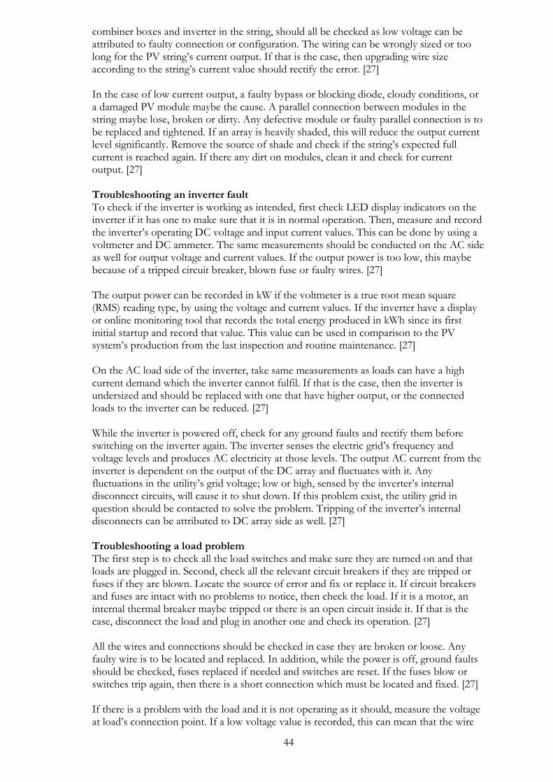
44
combiner boxes and inverter in the string, should all be checked as low voltage can be attributed to faulty connection or configuration. The wiring can be wrongly sized or too long for the PV string’s current output. If that is the case, then upgrading wire size according to the string’s current value should rectify the error. [27] In the case of low current output, a faulty bypass or blocking diode, cloudy conditions, or a damaged PV module maybe the cause. A parallel connection between modules in the string maybe lose, broken or dirty. Any defective module or faulty parallel connection is to be replaced and tightened. If an array is heavily shaded, this will reduce the output current level significantly. Remove the source of shade and check if the string’s expected full current is reached again. If there any dirt on modules, clean it and check for current output. [27] Troubleshooting an inverter fault To check if the inverter is working as intended, first check LED display indicators on the inverter if it has one to make sure that it is in normal operation. Then, measure and record the inverter’s operating DC voltage and input current values. This can be done by using a voltmeter and DC ammeter. The same measurements should be conducted on the AC side as well for output voltage and current values. If the output power is too low, this maybe because of a tripped circuit breaker, blown fuse or faulty wires. [27] The output power can be recorded in kW if the voltmeter is a true root mean square (RMS) reading type, by using the voltage and current values. If the inverter have a display or online monitoring tool that records the total energy produced in kWh since its first initial startup and record that value. This value can be used in comparison to the PV system’s production from the last inspection and routine maintenance. [27] On the AC load side of the inverter, take same measurements as loads can have a high current demand which the inverter cannot fulfil. If that is the case, then the inverter is undersized and should be replaced with one that have higher output, or the connected loads to the inverter can be reduced. [27] While the inverter is powered off, check for any ground faults and rectify them before switching on the inverter again. The inverter senses the electric grid’s frequency and voltage levels and produces AC electricity at those levels. The output AC current from the inverter is dependent on the output of the DC array and fluctuates with it. Any fluctuations in the utility’s grid voltage; low or high, sensed by the inverter’s internal disconnect circuits, will cause it to shut down. If this problem exist, the utility grid in question should be contacted to solve the problem. Tripping of the inverter’s internal disconnects can be attributed to DC array side as well. [27] Troubleshooting a load problem The first step is to check all the load switches and make sure they are turned on and that loads are plugged in. Second, check all the relevant circuit breakers if they are tripped or fuses if they are blown. Locate the source of error and fix or replace it. If circuit breakers and fuses are intact with no problems to notice, then check the load. If it is a motor, an internal thermal breaker maybe tripped or there is an open circuit inside it. If that is the case, disconnect the load and plug in another one and check its operation. [27] All the wires and connections should be checked in case they are broken or loose. Any faulty wire is to be located and replaced. In addition, while the power is off, ground faults should be checked, fuses replaced if needed and switches are reset. If the fuses blow or switches trip again, then there is a short connection which must be located and fixed. [27] If there is a problem with the load and it is not operating as it should, measure the voltage at load’s connection point. If a low voltage value is recorded, this can mean that the wire
45
feeding the load is either too long or under rated and need to be replaced by an appropriately sized one to reduce the voltage drop. It can also be due to a load that is too large for the wire size in the circuit. You can either reduce the load, or use a larger wire. [27]

46
3 System Modelling, Calculations and Simulation The PV system presented in this chapter is designed for Högskolan Dalarna rooftop and the hut constructed on it. The aim of the designed system is not to achieve an optimal system performance; but rather to tailor the system’s design and available roof area towards building a system that will be used as an instructional tool. It is aimed at PV installers to educate them on the best practices to install a PV system, troubleshoot and maintain it according to the guidelines presented in this thesis.
Building location and orientation
Högskolan Dalarna is located in Borlänge (60° 29 ' 8.88 " N - 15° 26 ' 13.70 " E). The roof of the hut which the first PV sub-array will be built on is facing south as seen in Figure 3.1. The second PV sub-array will be facing south west direction at approximately 230o. The weather data used for the system’s simulation was from Meteonorm 7.1 imported directly from PVsyst. The data values were taken were taken between the years of 1991- 2010 for Borlänge.
Figure 3.1 Dalarna University on Google earth, to the left the University’s main campus building, to the right is the solar roof where the educational PV system will be built on the hut and on the front part of the
flat roof
Design considerations
The capacity and orientation of the PV system were determined by the usable area on the roof and hut, and how best to utilize it to design a system for installers with an ample surrounding space to install the system as seen in Figure 3.3.

47
Figure 3.3 Layout for the PV system and sub-arrays
Sub-array one will be installed on the hut on the right hand side as the other areas on the surface are used for other existing systems. The tilt angle of the hut is an accurate 43o. The dimensions of the area allocated for array one is approximately 5 m in width and 3.6 m in length. The clearance area in front of the array is approximately 4 m, which should give plenty of space for installers to fix the system and use scaffolds for height safety.
Sub-array two will be installed at the front end of the roof. There are no area restrictions here as the chosen space is completely free of any other structures. The PV modules will be mounted on a ballast system that have an adjustable tilt angle that ranges from 10o- 20o. The area that will be occupied by the system is approximately 7 m in width and 2.5 m in length. It is worth noting that the two weight support beams on the roof near the arrays, will be removed in the near future. This will be beneficial especially for array two, as it can be oriented towards true south direction as the hut; if optimal performance and data collection from the system were needed.
System Design
The PV system was designed on Sketchup software after making the necessary calculations required to verify the amount of modules in each array and their configuration. The next step was to simulate the system on PVsyst to verify the system, chosen components and other areas which will be discussed in PVsyst subsection 3.3.3. The third step was to make a bill of materials (BOM) for the various components in the system, mounting structures, cables and all the relevant main materials that installers will need to assemble the system. Last but not least, a single line electrical diagram was drawn on AutoCAD, as an elaboration for installers to see how the PV modules are connected together and how the two arrays will be connected to the inverter.
48
3.3.1. System Calculations
The first system in the design process was to make the calculations necessary to size the inverter, determine the number of modules in each string and make sure that the solar array falls within the boundary specifications of the selected inverter. The PV system is dived into two sub-arrays of equal capacity and number of modules. Each sub array is rated at 2.08 kW, for a total combined capacity of 4.16 kW. The PV modules chosen for the system were Luxor 260 W Polycrystalline modules, and the inverter is SMA SUNNYBOY 3.6 kW that is characterized with two independent MPPT inputs for the two strings. The manual system calculations are important to ensure that the modules are compatible with the inverter chosen. Too few PV modules in series will make the inverter unable to maintain the PV array’s MPP under high temperatures at the selected location, which will result in less than optimal energy harvesting. On the other hand, too many PV modules in series can result in cumulative voltages that exceed the inverter’s maximum allowable voltage at 600 V DC, causing a fatal damage to the inverter.[28] It is critical to match the solar array’s output to the inverter’s input. The primary objective is to ensure that the inverter take a high percentage of the harvested energy by the solar array during various environmental conditions. The secondary objective is to maximize the inverter’s capacity so that it can operate near its full power when there are high irradiance periods. The inverter’s power limiting should only occur during transitional conditions or for rare occasions, and not under normal operating conditions. [28] The number of modules in series and the number of strings will depend entirely on various parameters. The parameters are the input current and voltage values of the inverter, the electrical values of the module and the average or anticipated high and low ambient temperatures at the selected location. The array’s operating voltage and current values must be within the inverter’s operating ranges all the time at all weather conditions. [28] Maximum number of PV modules in series The maximum input voltage value of an inverter is the parameter which decides the limit of an array size. Exceeding that value will result in irreversible damage to the inverter and can cause catastrophic effects on the whole system’s location. It can also result in a direct
violation for a country’s NEC. The maximum open circuit voltage (𝑉𝑜𝑐) of a PV module is the most important value in PV array design. [28]
The array’s open circuit voltage is derived from the number of modules in series. The 𝑉𝑂𝐶 must be temperature corrected to get the maximum system voltage, because voltage
depends on temperature. The corrected 𝑉𝑂𝐶 will verify the maximum number of PV modules in series in the string. Usually, system designers take the lowest ambient temperature recorded at the desired location to do the calculations.[28]
The maximum module voltage (𝑉𝑂𝐶𝑚𝑎𝑥) can be calculated from equation 3.1: [28]
𝑉𝑂𝐶𝑚𝑎𝑥= 𝑉𝑂𝐶 + (𝑇𝑚𝑖𝑛 − 𝑇𝑆𝑇𝐶) ⋅ 𝛽𝑉𝑜𝑐
Equation 3.1
Where 𝑇𝑚𝑖𝑛 is the minimum ambient temperature at the location and is taken as -25 0C
for Borlänge, 𝑇𝑆𝑇𝐶 is the temperature under standard test conditions at 25oC, 𝛽𝑉𝑜𝑐 is the
temperature coefficient of 𝑉𝑂𝐶 . The module 𝑉𝑂𝐶 and 𝛽𝑉𝑜𝑐 values can both be found in
the module’s manufacturer data sheet, which is included in the Appendix.

49
The maximum allowable DC input voltage for SUNNYBOY 3.6 is 600 V. To determine the maximum number of PV modules in series, the inverter’s input voltage is divided by the maximum module’s voltage:
𝑁𝑚𝑎𝑥 =𝑉𝑖𝑛𝑣𝑚𝑎𝑥
𝑉𝑂𝐶𝑚𝑎𝑥
Equation 3.2
Where 𝑉𝑖𝑛𝑣𝑚𝑎𝑥 is the maximum input voltage for the inverter.
The maximum number of PV modules are thus 14 modules.
Minimum number of PV modules in series
A low PV array’s voltage will have a significant negative effect on a PV system’s energy production. The array voltage must not be below the minimum operating voltage of an inverter, otherwise the inverter will fail to track the maximum power point of PV array. In addition, the inverter can shut down on days that have high temperatures, resulting in poor performance of the system. [28]
To determine the minimum number of PV modules in series, the PV module’s
temperature corrected maximum voltage (𝑉𝑚𝑝𝑚𝑖𝑛), must be calculated at the average high
ambient temperature of the installation location. The actual module’s cell temperature
(𝑇𝑟𝑖𝑠𝑒) associated with the mounting method used for the system should be estimated.
𝑇𝑟𝑖𝑠𝑒 can be assumed to be 30 oC for PV systems mounted near roof surfaces; based on
empirical data. If another mounting method is used for the system, 𝑇𝑟𝑖𝑠𝑒 can be estimated between 20 oC – 25 oC because of the improved airflow around the modules. [28]
The PV module’s temperature corrected maximum voltage can be estimated from equation 3.1: [28]
𝑉𝑚𝑝𝑚𝑖𝑛= 𝑉𝑚𝑝 + ((𝑇𝑟𝑖𝑠𝑒 + 𝑇𝑚𝑎𝑥 − 𝑇𝑆𝑇𝐶). ( 𝛽𝑣𝑚𝑝. 𝑉𝑚𝑝)) Equation3.3
Where 𝑉𝑚𝑝𝑚𝑖𝑛 is the module’s temperature corrected maximum voltage, 𝑉𝑚𝑝 the module’s
rated voltage at maximum power point, 𝑇𝑟𝑖𝑠𝑒 is temperature rise from actual mounting
method, 𝑇𝑚𝑎𝑥 is the maximum high temperature at the location, and 𝑇𝑆𝑇𝐶 is temperature value at standard test conditions. The minimum input voltage of SMA SUNNYBOY 3.6 is 125 V. This means that the minimum number of modules connected in series in the string must be greater than that value: [28]
𝑁𝑚𝑖𝑛 =𝑉𝑖𝑛𝑣𝑚𝑖𝑛
𝑉𝑚𝑝𝑚𝑖𝑛
Equation 3.4
Where 𝑁𝑚𝑖𝑛 is the minimum number of modules in series,𝑉𝑖𝑛𝑣𝑚𝑖𝑛 is the minimum input
voltage of the inverter and 𝑉𝑚𝑝𝑚𝑖𝑛 is the module’s temperature corrected maximum
voltage. Therefore, the minimum number of PV modules in series is 5 modules. After the completion of the calculations, it is now apparent that the maximum number of modules connected in series must not exceed 13 modules, and minimum number is not less than 5 modules in order to match the PV array with the inverter’s specifications.
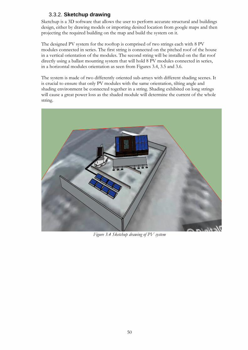
50
3.3.2. Sketchup drawing
Sketchup is a 3D software that allows the user to perform accurate structural and buildings design, either by drawing models or importing desired location from google maps and then projecting the required building on the map and build the system on it. The designed PV system for the rooftop is comprised of two strings each with 8 PV modules connected in series. The first string is connected on the pitched roof of the house in a vertical orientation of the modules. The second string will be installed on the flat roof directly using a ballast mounting system that will hold 8 PV modules connected in series, in a horizontal modules orientation as seen from Figures 3.4, 3.5 and 3.6. The system is made of two differently oriented sub-arrays with different shading scenes. It is crucial to ensure that only PV modules with the same orientation, tilting angle and shading environment be connected together in a string. Shading exhibited on long strings will cause a great power loss as the shaded module will determine the current of the whole string.
Figure 3.4 Sketchup drawing of PV system
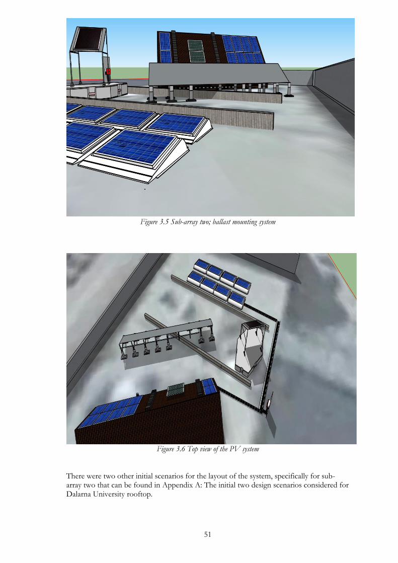
51
Figure 3.5 Sub-array two; ballast mounting system
Figure 3.6 Top view of the PV system
There were two other initial scenarios for the layout of the system, specifically for sub-array two that can be found in Appendix A: The initial two design scenarios considered for Dalarna University rooftop.

52
3.3.3. PVsyst simulation
The system with the chosen PV modules and inverter were simulated on PVsyst. All the electrical characteristics were entered, the 3D scene that was designed on Sketchup was imported to PVsyst for an accurate shading analysis of the system as seen in Figure 3.7.
Figure 3.7 Shading analysis in PVsyst
It is important to note that shading on sub-array one on the hut will not be a problem. This is because of the clear area around it and the fact that the height of the wall opposite to it is only about 1.75 m high. One the other hand, shading is a problem with sub-array two as it is too close to the surrounding walls which stand at 2 m – 2.5 m high. It is inevitable that there is great amount of shading during winter months because of the position of the sub-array. However, as stated previously, system performance was not the first priority when designing the system. The priority was constructing a system, which will be a learning platform for installers on how to install various PV systems appropriately according to the guidelines in this document. Cable calculations One of the important aspects when designing PV systems is to choose the correct diameter of DC cables used in the strings. Failure to do so can result in fire hazard of the whole system if the cable is undersized. If the cable is oversized, voltage drop will increase which leads to power loss. [29] The voltage of a string is the sum of individual voltages of each PV module connected in series in it. This voltage value is the one that will be applied to strings combiner box if present. [29]
𝑉𝑠𝑡𝑟𝑖𝑛𝑔 = 𝑉𝑀𝑃𝑃 ∗ 𝑁𝑚𝑜𝑑𝑢𝑙𝑒 Equation 3.3
Where VMPP is the voltage of an individual module at maximum power point, and
Nmodule is the number of PV modules connected in series in a string.

53
The current of a string is the same as the current value of a single PV module in the string. This is due to the fact that the modules are connected in series in a string. If there are many strings in the system, the current at the combiner box level that will be carried by the DC main cable will be the sum of the current of each string connected to the exact combiner box. For this PV system, this calculation is omitted as the strings are directly connected to the inverter.
𝐼 = 𝐼𝑀𝑃𝑃 ∗ 𝑁𝑠𝑡𝑟𝑖𝑛𝑔 Equation 3.4
Where IMPP is the current of a string at maximum power point and 𝑁𝑠𝑡𝑟𝑖𝑛𝑔 is the number of
strings per combiner box.
The current value for DC cables of each of the two strings designed will be 8.60 A, which is the value taken from the module’s manufacturer data sheet.
The maximum voltage drop that can occur in cable must be according to the relevant country’s installations standards and codes. In some countries like Malaysia, the maximum allowable voltage drop must be less than 5% between the PV array and the inverter. [29]
Equation 3.5 is used to calculate the cross section of the cable: [3]
A= 𝐿 ⋅ 𝑃
3 %⋅𝑉𝑠𝑡𝑟𝑖𝑛𝑔⋅𝐾 Equation 3.5
Where L= Cable length (plus cable + Minus cable) (m)
P= Transferred power (W)
A= Cable cross section (mm2)
K= Electrical Conductivity of copper (m/Ω mm2)
Vstring= System voltage (V)
The 3% represents the assumed voltage drop in the cable. The chosen cable cross section area is thus 4 mm2, which is the standard for PV systems.
The PV system is now complete and the simulation report generated by PVsyst can be located in Appendix D: PVsyst simulation report for the designed PV system on Högskolan Dalarna roof.
3.3.4. Electrical drawing
The final step in the system design was to construct a single line electrical drawing on AutoCAD Electrical. The schematic should be used by the system’s installers as a reference when mounting the system. It is important that installers know how to read electrical drawings and be able to translate it to the working ground. Residential PV systems are relatively uncomplicated, and installers must have the necessary knowledge to distinguish between parallel and series string connections. Wiring of PV modules together is perhaps the most crucial step on the DC side of PV systems installations. Any electrical schematic associated with the installation plan must be referred to at all times.

54
There are no standard procedures to do the electrical drawings on AutoCAD. It entirely depend on the design engineer, the complexity of the system to be designed, and how much details should be included in the schematic. Figure 3.8 is the AutoCAD Electrical drawing of the PV system designed.
Figure 3.8 PV system electrical diagram
Notice the orientation of PV modules in row one in sub-array 1. They are upside down to reduce the distance between (+) and (-) cables to minimize antenna losses. The same was done for sub-array 2 with modules number PV9 and PV16. It is always beneficial to put the sequence and orientation of system’s strings in the correct order on schematic drawing. This will make it easier for installers to visualize it as it mimics how the installed system will look like. The modules in each string are all connected in series and numbered accordingly. The two cable leads; the positive and negative, from each string will be directly connected to each of the two inverter’s DC inputs. There was no need for a combiner box and DC main cable for the two strings as it is a small system.
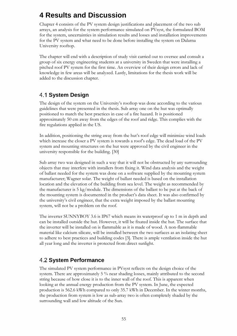
55
4 Results and Discussion Chapter 4 consists of the PV system design justifications and placement of the two sub arrays, an analysis for the system performance simulated on PVsyst, the formulated BOM for the system, uncertainties in simulation results and losses and installation improvements for the PV system and what need to be done before installing the system on Dalarna University rooftop. The chapter will end with a description of study visit carried out to oversee and consult a group of six energy engineering students at a university in Sweden that were installing a pitched roof PV system for the first time. An overview of their design errors and lack of knowledge in few areas will be analyzed. Lastly, limitations for the thesis work will be added to the discussion chapter.
System Design
The design of the system on the University’s rooftop was done according to the various guidelines that were presented in the thesis. Sub array one on the hut was optimally positioned to match the best practices in case of a fire hazard. It is positioned approximately 50 cm away from the edges of the roof and ridge. This complies with the fire regulations applied in the US. In addition, positioning the string away from the hut’s roof edge will minimize wind loads which increase the closer a PV system is towards a roof’s edge. The dead load of the PV system and mounting structures on the hut were approved by the civil engineer in the university responsible for the building. [30] Sub array two was designed in such a way that it will not be obstructed by any surrounding objects that may interfere with installers from fixing it. Wind data analysis and the weight of ballast needed for the system was done on a software supplied by the mounting system manufacturer; Wagner solar. The weight of ballast needed is based on the installation location and the elevation of the building from sea level. The weight as recommended by the manufacturer is 5 kg/module. The dimensions of the ballast to be put at the back of the mounting system is documented in the product’s data sheet. It was also confirmed by the university’s civil engineer, that the extra weight imposed by the ballast mounting system, will not be a problem on the roof. The inverter SUNNYBOY 3.6 is IP67 which means its waterproof up to 1 m in depth and can be installed outside the hut. However, it will be fixated inside the hut. The surface that the inverter will be installed on is flammable as it is made of wood. A non-flammable material like calcium silicate, will be installed between the two surfaces as an isolating sheet to adhere to best practices and building codes [3]. There is ample ventilation inside the hut all year long and the inverter is protected from direct sunlight.
System Performance
The simulated PV system performance in PVsyst reflects on the design choice of the system. There are approximately 5 % near shading losses, mainly attributed to the second string because of how close it is to the inner wall of the roof. This is apparent when looking at the annual energy production from the PV system. In June, the expected production is 562.6 kWh compared to only 35.7 kWh in December. In the winter months, the production from system is low as sub-array two is often completely shaded by the surrounding wall and low altitude of the Sun.
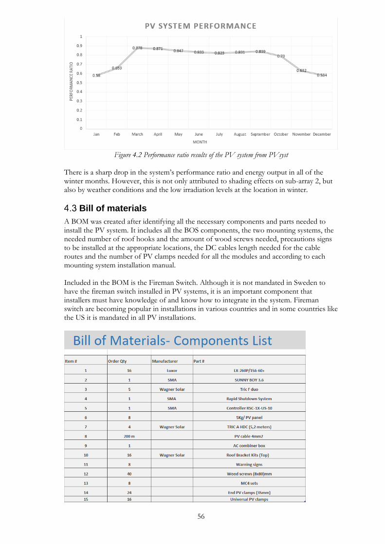
56
Figure 4.2 Performance ratio results of the PV system from PVsyst
There is a sharp drop in the system’s performance ratio and energy output in all of the winter months. However, this is not only attributed to shading effects on sub-array 2, but also by weather conditions and the low irradiation levels at the location in winter.
Bill of materials
A BOM was created after identifying all the necessary components and parts needed to install the PV system. It includes all the BOS components, the two mounting systems, the needed number of roof hooks and the amount of wood screws needed, precautions signs to be installed at the appropriate locations, the DC cables length needed for the cable routes and the number of PV clamps needed for all the modules and according to each mounting system installation manual. Included in the BOM is the Fireman Switch. Although it is not mandated in Sweden to have the fireman switch installed in PV systems, it is an important component that installers must have knowledge of and know how to integrate in the system. Fireman switch are becoming popular in installations in various countries and in some countries like the US it is mandated in all PV installations.
57
Figure 4.1 The designed PV system BOM. The vacant cells in manufacturer column are to be completed when settling on the appropriate seller in Sweden.
Uncertainties
There are three uncertainties associated with the system.
1. Soiling effects on the energy output of the PV system due to snow in the winter months. There is no accurate method to quantify the amount of snow that will fall on the modules Even if the values can be retrieved from meteorological data, the period, accumulation level of snow on PV modules and whether the module is partially or fully shaded, are very hard factors to determine. PVsyst does not offer a snow loss modeling due to the complexity of few factors like effect of snow on cell temperatures, insolation, tilt angle and evaluation of electrical mismatch effect in the case of partial shading. Different percentages of soiling were added to the simulation result with ranges from 10 % - 20 % for the winter months starting in November till February. Energy losses due to soiling effects were estimated at 1.6 % in PVsyst report. However, that value can be slightly higher or lower depending on the user’s estimation and input values for each month. In addition, while taking the University’s roof measurements for sub-array two, it was done during winter months. The roof was completely covered in snow at a level not less than 70 cm. Sub-array two will be installed on a ballast mounting system. Ballast systems sit low on flat roofs and will be completely covered by snow in winter months. However, this is unavoidable and the majority of ballast mounting systems installed in Sweden don’t have an up-keep and maintenance routine for winter months, to shovel snow on top of modules. It is not recommended to shovel snow on PV systems because the glass surface can be easily scratched or damaged by the metal surface of a shovel.
2. PVsyst uncertainty. Modelling a system with a simulation software like PVsyst is considered a source of uncertainty to end results. The degree of uncertainty varies between 3 % - 5 % since it is not easy to distinguish between errors due to input values or due to modelling of a system. [31]
3. Cable losses. There were two cable routes designed for the system. One of the bale routes will require approximately 15 m extra DC cables to connect to the inverter. It is not confirmed yet what route will be used for the system’s installation. However, the simulation done on PVsyst were done using the long routing option and the recorded system losses due to Ohmic losses were less than 1 %. This value can be slightly less depending on the route choice.
The PV system performance is sacrificed for practically. The system is designed as a learning platform for installers to assemble, connect and install a PV system mechanically and electrically correctly, according to best practices and taking into account the applicable standards and codes.
Installation improvements
The PV system was designed assuming that the installation surroundings will remain the same. However, there are a few reservations that should be addressed before commencing with the system installation plan.

58
• The inverter’s location. The inverter will be installed inside the hut near the door. However, there are many electrical equipment near the inverter’s location and few spare PV modules. This should all be cleared away from the inverter due to fire hazards for any occasions like an electric arc. It must also be stressed that a customized non-flammable sheet be installed at the back of the inverter as the hut wall is made of wood.
• The condition of the hut’s underlayment. The hut is more than 10 years old and it was rarely being inspected, especially when it comes to internal structuring. The state of the roof and its underlayment material should be inspected before drilling holes and installing rails mounting system for sub-array one. If there is any problem with the underlayment material, it should be rectified and restored or fully replaced if needed.
• The condition of the flat roof in sub-array two location. The state of the roof in that particular area is not great. There are visible billowing and uneven distribution in the roof’s material at that location. Adding more weight to it may increase the billowing effect and the ballast system will not sit even on the surface. Although the building’s civil engineer confirmed that the roof can handle the extra weight, the condition of the roof surface should be re-assessed, since the system will be used as an educational platform for installers and there will be constant foot presence on the roof.
Study visit
A group of six students in their bachelor’s degree in Energy engineering from Uppsala University in Sweden were working on a pitched roof PV system design. The system was to be installed on a mock up model of a pitched roof on the ground for educational purposes in an energy center. The author of this thesis was present during the system installation which was carried out by the six student engineers. However, there were glaring mistakes in the installation plan, the roof structure and the system installation that can be summed up as follow:
• The inverter was mounted to the side of the roof, exposed to all weather conditions. There were no careful considerations to its location or how the cable routing will be directed. The inverter was also IP21 rated which means it is not suitable for outside conditions and that it is not waterproof. Direct sunlight exposure was not assessed when choosing its location. In addition, it was directly mounted on the roof’s wooden structure which is flammable. A non -flammable material sheet must be installed between the two surfaces to prevent fire hazards.
• The roof structure was not correct regarding rafters and battens. They were wrongly spaced, and they were both inaccessible to mount roof hooks. The students wanted to install hooks on the thin, fragile wood that covers the roof as seen in Figure 4.2. This clearly violates buildings codes and if it was installed that way, the PV system would have collapsed by wind forces over time.
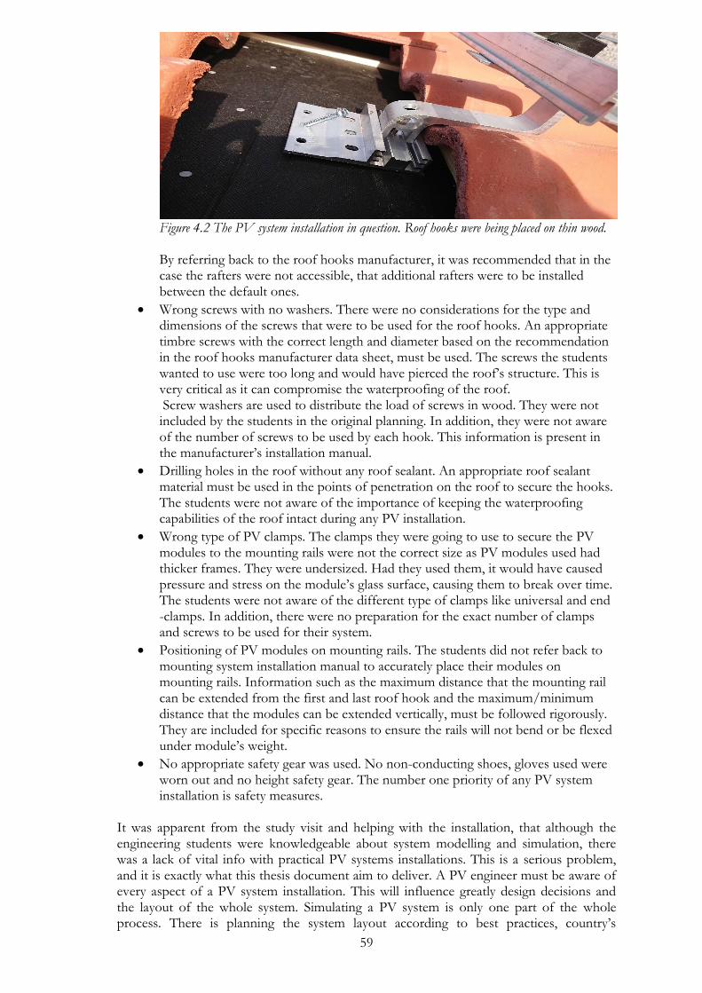
59
Figure 4.2 The PV system installation in question. Roof hooks were being placed on thin wood. By referring back to the roof hooks manufacturer, it was recommended that in the case the rafters were not accessible, that additional rafters were to be installed between the default ones.
• Wrong screws with no washers. There were no considerations for the type and dimensions of the screws that were to be used for the roof hooks. An appropriate timbre screws with the correct length and diameter based on the recommendation in the roof hooks manufacturer data sheet, must be used. The screws the students wanted to use were too long and would have pierced the roof’s structure. This is very critical as it can compromise the waterproofing of the roof. Screw washers are used to distribute the load of screws in wood. They were not included by the students in the original planning. In addition, they were not aware of the number of screws to be used by each hook. This information is present in the manufacturer’s installation manual.
• Drilling holes in the roof without any roof sealant. An appropriate roof sealant material must be used in the points of penetration on the roof to secure the hooks. The students were not aware of the importance of keeping the waterproofing capabilities of the roof intact during any PV installation.
• Wrong type of PV clamps. The clamps they were going to use to secure the PV modules to the mounting rails were not the correct size as PV modules used had thicker frames. They were undersized. Had they used them, it would have caused pressure and stress on the module’s glass surface, causing them to break over time. The students were not aware of the different type of clamps like universal and end -clamps. In addition, there were no preparation for the exact number of clamps and screws to be used for their system.
• Positioning of PV modules on mounting rails. The students did not refer back to mounting system installation manual to accurately place their modules on mounting rails. Information such as the maximum distance that the mounting rail can be extended from the first and last roof hook and the maximum/minimum distance that the modules can be extended vertically, must be followed rigorously. They are included for specific reasons to ensure the rails will not bend or be flexed under module’s weight.
• No appropriate safety gear was used. No non-conducting shoes, gloves used were worn out and no height safety gear. The number one priority of any PV system installation is safety measures.
It was apparent from the study visit and helping with the installation, that although the engineering students were knowledgeable about system modelling and simulation, there was a lack of vital info with practical PV systems installations. This is a serious problem, and it is exactly what this thesis document aim to deliver. A PV engineer must be aware of every aspect of a PV system installation. This will influence greatly design decisions and the layout of the whole system. Simulating a PV system is only one part of the whole process. There is planning the system layout according to best practices, country’s

60
regulations, building codes and fire codes. In addition, there is the system installation phase. A solar design engineer maybe required to oversee a system installation. The engineer must be aware of every installation step as he may be required to supervise the system’s installation, be a guidance to installers when necessary and finally responsible of system commissioning. PV systems engineers are tasked with making a BOM after completing a system’s design. This have to include everything from BOS components to how many screws and washers are needed. It have to be reiterated again that a PV system engineer is not only responsible for a system’s design and simulate its predicted energy yield. The engineer have to be comprehensive until commissioning documents are handed out to end users.
Limitations
The thesis content are mainly focused on regulations from US and some countries in EU like Germany and UK. The US specifically have the most complete standards when it comes to PV installations. States like California which is now a leader in Solar systems, have been adding more stringent and strict rules for PV installations since 2006. The California fire department have issued a guide for the safety of PV systems and firefighters in case of a fire break out. And they have instructions that must be followed by all PV installation companies to ensure the safety of the system and that firefighters are not obstructed from performing their critical job when there are fire outbreaks. There were too many incidents in the US where complete buildings were burnt down because of PV systems. In those cases, firefighters refused to go on rooftops to put down the fire because of the live DC cables which endangered their lives. That is why now in California fire codes for PV systems, they mandate specific firefighter’s routes with specific dimensions and width on flat roof installations for emergency cases and to allow firemen to perform their job. Those standards are now mandated in the majority of US states. So, the question becomes, can the various standards be applied here in Sweden? The answer is yes, and it should. All the various standards discussed in the thesis from various countries are important to implement in the Swedish solar market. There are already regulation in the Swedish NEC, but there are still no standards when it comes to safety standards like arc fault circuit interrupters (AFCI), firefighter switch and firefighters and no regulations for specific routes on pitched and flat roofs for fire hazards situations. In addition, particularly for pitched roofs installations, in the US penetration of roofs must comply with the roofing company and building codes. Roofing companies must approve a PV system installation and they must oversee the roof’s waterproof sealing after drilling holes in the roof. All the roofs are covered by warranties and any non- optimal installation that may compromise the integrity or the original function of the roof, will void its warranties. Such strict rules and emphasize on safety should be applied in Sweden. PV systems are supposed to function for 20 years or more, and more often than not, that does not happen because of bad installations workmanship. The standards and regulations present in the US are applied in all the states and the majority of them are justifiable and can be added here in Sweden. The statement “PV systems are generally safe” is not accurate. It is only safe to the structure it is installed on if all the standards and best practices like the ones presented here are followed during installation. Otherwise, PV systems can indeed be catastrophic and fire prone due to bad electrical and mechanical installations.

61
5 Conclusions This thesis work was aimed at making a comprehensive guide for PV systems installers and junior engineers who are required to have a solid foundation and a certain level of knowledge on how PV systems are installed. The guide is not limited to one type of PV system. It can be used as a reference to any PV system installation, with emphasize on flat and pitched roofs installations. Best practices and standards implemented in some countries that involves fire hazards safety considerations and NEC codes that must be followed in the US, Germany and UK were complied. A troubleshooting error scheme was conducted to guide installers on the necessary steps to perform to rectify an operational error in a PV system. The scheme can be used on all on-grid PV systems regardless of the mounting system used. Last but not least, a new PV system with two sub arrays consisting of a pitched roof mounting system and a ballast mounting system were 3D designed on Sketchup, Verified and simulated on PVsyst and an electrical diagram of the system was developed on AutoCAD electrical. The system will be used as an educational tool for installers to fix the PV system according to the guidelines in the thesis, commission and troubleshoot it for operational errors.
Future work
A questionnaire for Swedish PV installations companies should be conducted and statistical data can be collected. It is important to know what installations companies need from their installers before hiring them. In developing countries, an installer always work under the supervision of a technician or an electrical engineer to guide them to all installations procedures, positioning and connecting of PV modules in an array. Installers in such countries do not have the technical knowledge and scope of installations. However, this is different in Sweden and developed countries because of the higher wages. Installers must have good knowledge about PV systems, perform various installation tasks, and be able to read electrical and mechanical schematics. A list of some questions that can be aimed at installation companies is included in Appendix 6.7. In addition, a compilation of standards and PV systems installation electrical codes that must be adhered to in Sweden; is an important task to be performed as future work. Lastly, off-grid PV systems were not included in this thesis work. They have different procedures when it comes to commissioning, troubleshooting errors and storing BOS components in specific locations.
62
6 References [1] J. Lindahl, “National Survey Report of PV Power Applications in Sweden,” Upps. Univ.
Int. Energy Agency Upps. Swed., 2014. [2] E. SICO, “GREEN JOB ANALYSIS REPORT.” [3] D. G. für Sonnenenergie (DGS), Planning and installing photovoltaic systems: a guide for
installers, architects and engineers. Routledge, 2013. [4] W. Brooks and J. Dunlop, NABCEP PV Installation Professional Resource Guide. North
American Board of certified Energy Practitioners. 2013. [5] R. Mayfield, Flat roof mounting systems-solutions for the wide open commercial landscape.
SolarPro, 2009. [6] E. A. Franklin, Mounting Your Solar Phtovoltaic (PV) System. College of Agriculture,
University of Arizona (Tucson, AZ), 2017. [7] S. Namikawa and et.al, “Photovoltaics and Firefighters’ Operations: Best Practices in
Selected Countries,” Paris,FA, IEA-PVPS T12-09:2017, Apr. 2017. [8] H. Laukamp et al., “PV fire hazard-analysis and assessment of fire incidents,” 26th
EUPVSEC, 2013. [9] R. Authority, “RC62: RC62: Recommendations for fire safety with photovoltaic panel
installations.” RISCAuthority, Feb-2016. [10] M. Stornetta and J. Garcia, “Designing for Fire Code Compliance: Commercial
Rooftop PV Arrays,” no. 7.5, Aug-2014. [11] “SolarPro Magazine.” [Online]. Available: /articles/design-installation/dc-arc-fault-
circuit-protection-for-pv-systems. [Accessed: 02-Feb-2018]. [12] “SolarPro Magazine.” [Online]. Available: /articles/design-installation/fall-protection-
systems. [Accessed: 03-Feb-2018]. [13] “OSEIA Solar Safety 12-06 | Personal Protective Equipment | Occupational Safety
And Health Administration,” Scribd. [Online]. Available: https://www.scribd.com/document/46253277/OSEIA-Solar-Safety-12-06. [Accessed: 03-Feb-2018].
[14] PVTRIN, “Handbook for the Solar Installer,” TUC, GR, 2018. [15] Clean Energy Council, “Clean Energy Council Install And Supervise Guidlines For
Acrredited Installers,” 11, May 2017. [16] “Guide to the installation of pv systems 2nd edition,” Issuu. [Online]. Available:
https://issuu.com/kanagagnana/docs/guide_to_the_installation_of_pv_sys. [Accessed: 10-Feb-2018].
[17] F. Christian, “PHOTOVOLTAIC INSTALLATION BEST PRACTICES IN DUE CONSIDERATION OF ELECTROMAGNETIC RADIATION (DRAFT),” p. 12.
[18] C. O’Brien, “Roof-Mounted Solar Photovoltaic Arrays: Technical Issues For The Roofing Industry.” Mar-2006.
[19] Yumpu.com, “ROOFS WITH PHOTOVOLTAIC SYSTEMS - Index S.p.A.,” yumpu.com. [Online]. Available: https://www.yumpu.com/en/document/view/22656251/roofs-with-photovoltaic-systems-index-spa. [Accessed: 20-May-2018].
[20] “SolarPro Magazine.” [Online]. Available: /articles/design-installation/tile-roof-applications. [Accessed: 21-May-2018].
[21] Balfour and N. B. Nash, Advanced Photovoltaic Installations. Jones & Bartlett Publishers, 2011.
[22] “Free Guide to Solar PV Commissioning and Testing | Seaward,” Seaward Group USA. [Online]. Available: http://www.seaward-groupusa.com/userfiles/free-guide-solar-pv-testing.php. [Accessed: 21-Mar-2018].
63
[23] “PV System Commissioning | Home Power Magazine.” [Online]. Available: /articles/solar-electricity/design-installation/pv-system-commissioning. [Accessed: 20-Mar-2018].
[24] “SolarPro Magazine.” [Online]. Available: /articles/design-installation/pv-system-commissioning. [Accessed: 26-Mar-2018].
[25] R. Auvil, “As photovoltaic systems become more commonplace, knowing how to troubleshoot one is a technician’s best bet for quality service during a call.,” p. 4.
[26] “HiQ Solar - Home.” [Online]. Available: http://www.hiqsolar.com/. [Accessed: 02-Apr-2018].
[27] “Troubleshooting Photovoltaic Systems,” Electrical Construction & Maintenance (EC&M) Magazine, 21-Jun-2011. [Online]. Available: http://www.ecmweb.com/contractor/troubleshooting-photovoltaic-systems. [Accessed: 06-Apr-2018].
[28] “SolarPro Magazine.” [Online]. Available: /articles/design-installation/array-to-inverter-matching. [Accessed: 25-May-2018].
[29] A. D. Mosheer and C. K. Gan, “OPTIMAL SOLAR CABLE SELECTION FOR PHOTOVOLTAIC SYSTEMS,” Int. J. Renew. Energy Resour., vol. 5, no. 2, pp. 28–37, 2015.
[30] “SolarPro Magazine.” [Online]. Available: /articles/design-installation/wind-load-analysis-for-commercial-roof-mounted-arrays. [Accessed: 30-May-2018].
[31] D. Thevenard and S. Pelland, “Estimating the uncertainty in long-term photovoltaic yield predictions,” Sol. Energy, vol. 91, pp. 432–445, May 2013.
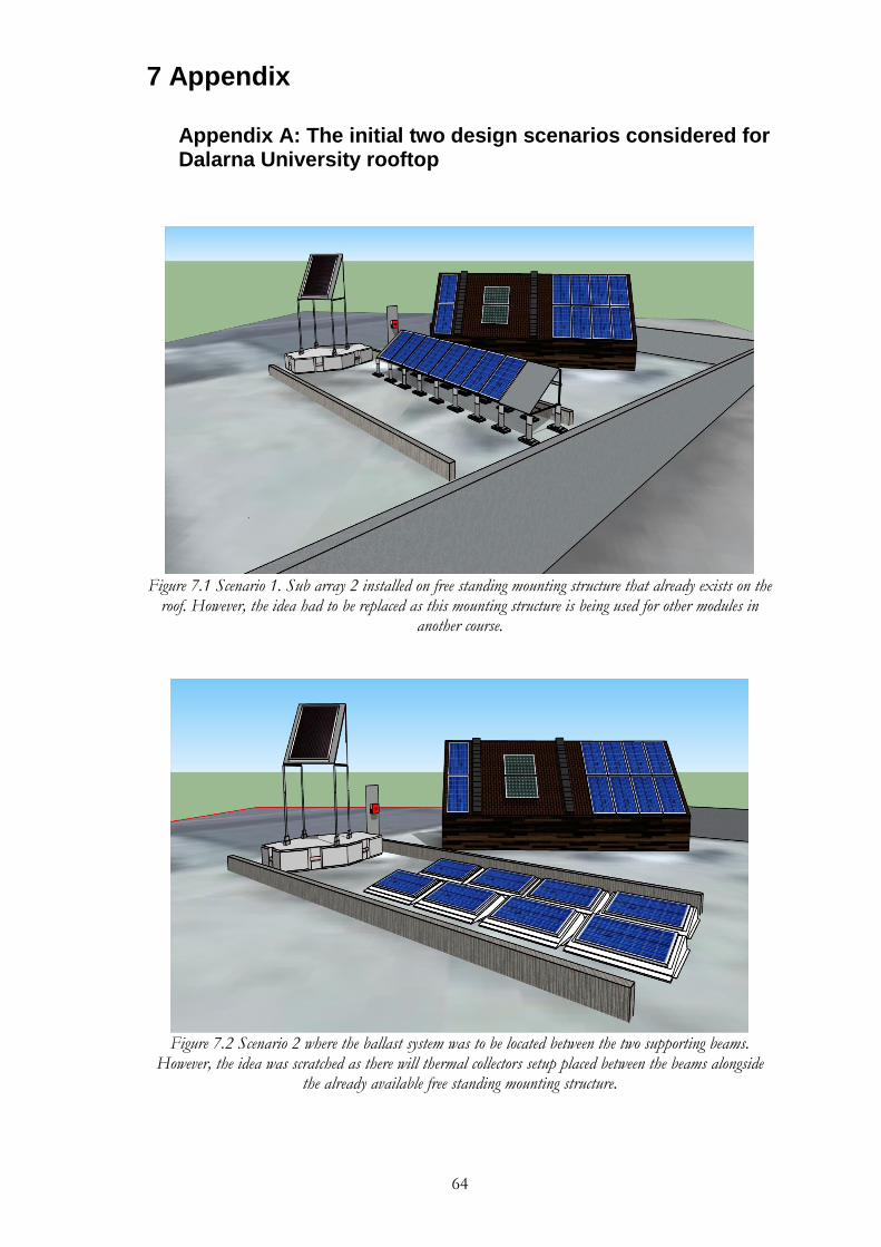
64
7 Appendix
Appendix A: The initial two design scenarios considered for Dalarna University rooftop
Figure 7.1 Scenario 1. Sub array 2 installed on free standing mounting structure that already exists on the
roof. However, the idea had to be replaced as this mounting structure is being used for other modules in another course.
Figure 7.2 Scenario 2 where the ballast system was to be located between the two supporting beams.
However, the idea was scratched as there will thermal collectors setup placed between the beams alongside the already available free standing mounting structure.
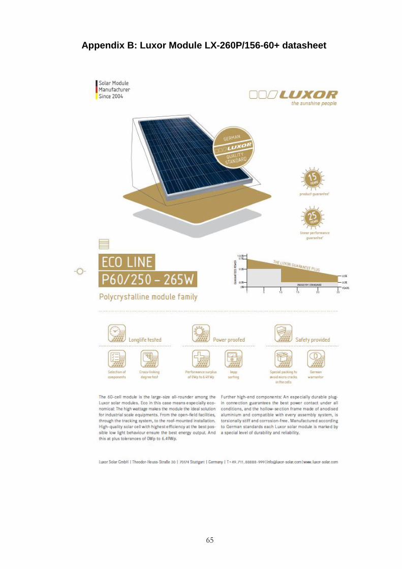
65
Appendix B: Luxor Module LX-260P/156-60+ datasheet
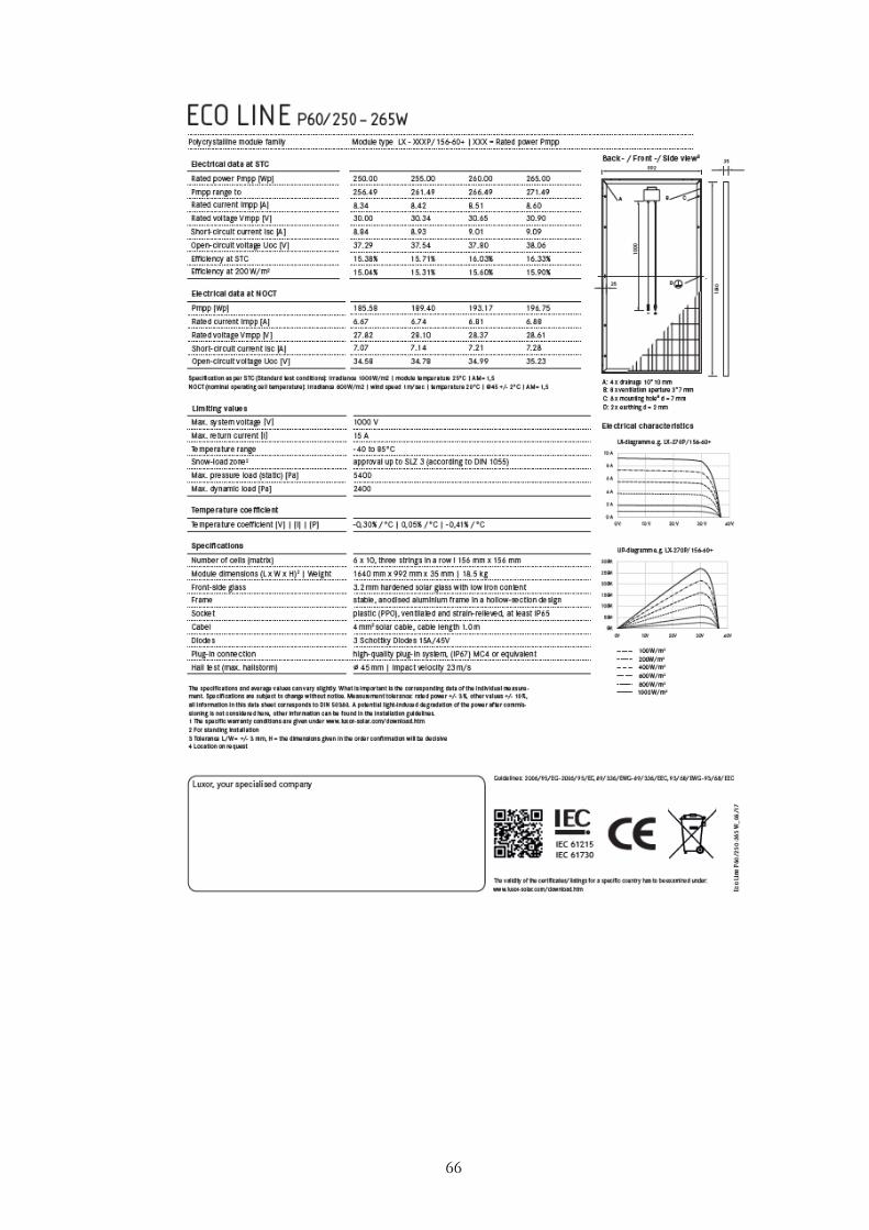
66

67
Appendix C: Inverter SMA SUNNYBOY 3.6 datasheet

68

69
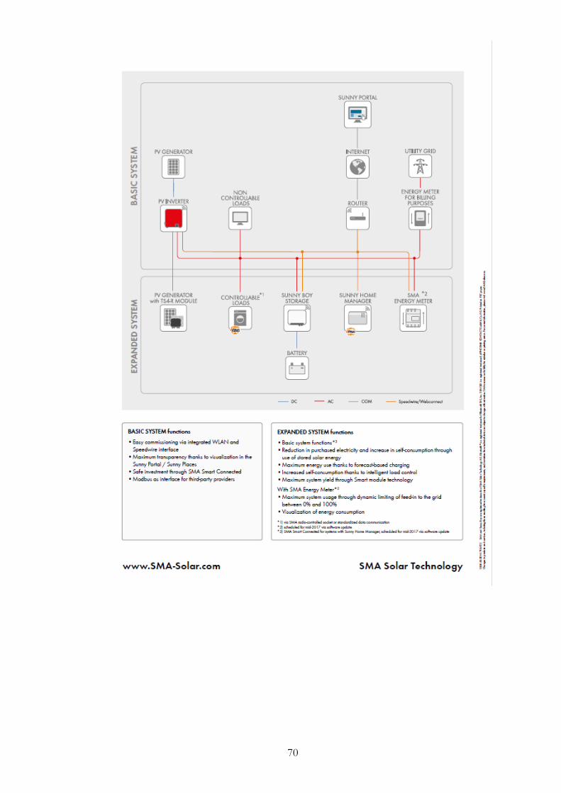
70
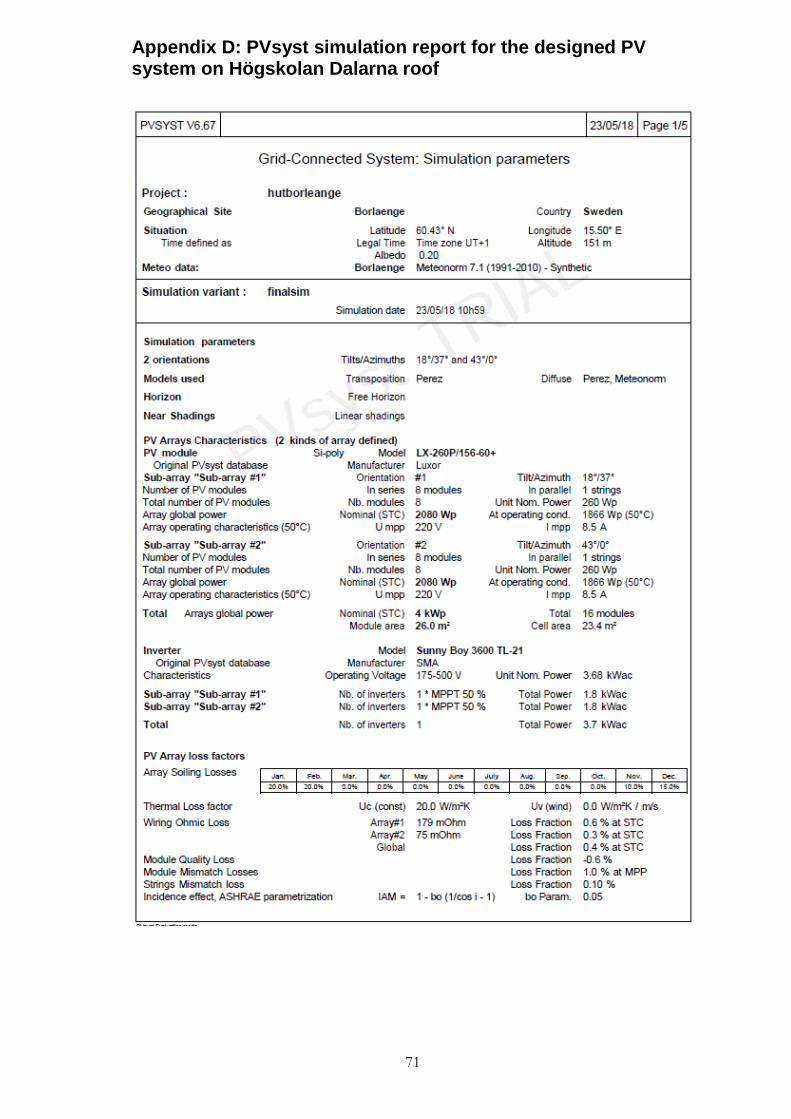
71
Appendix D: PVsyst simulation report for the designed PV system on Högskolan Dalarna roof
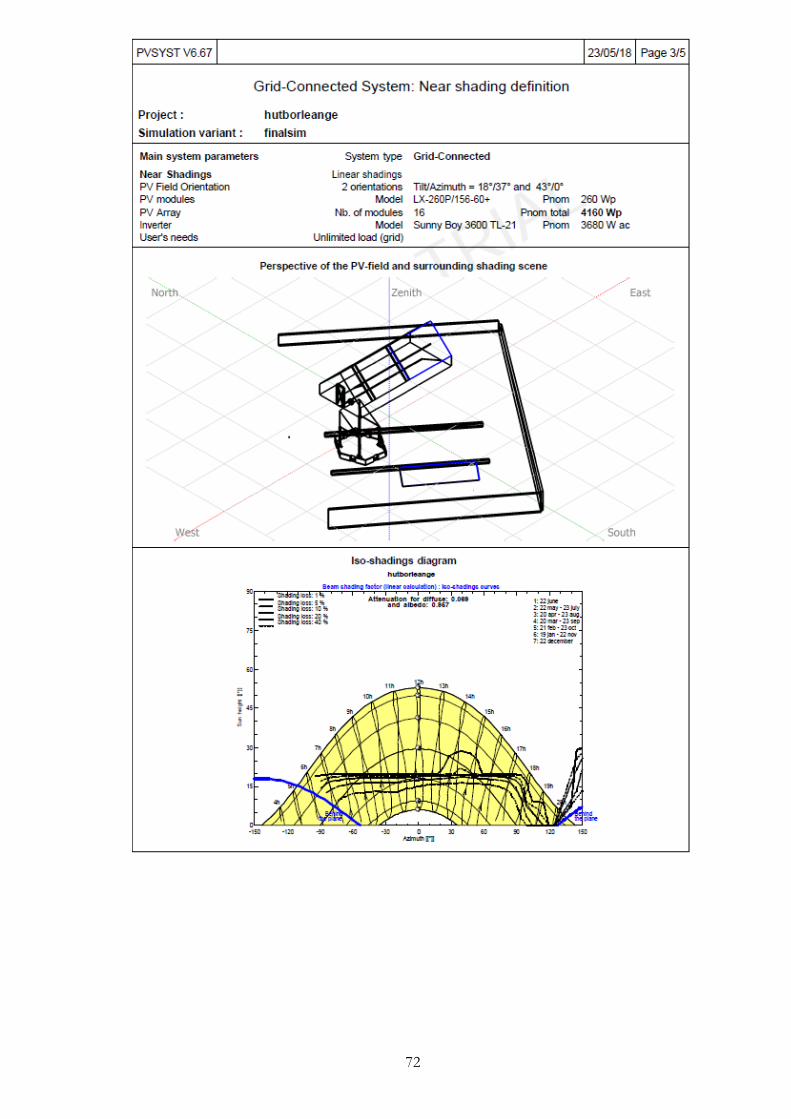
72
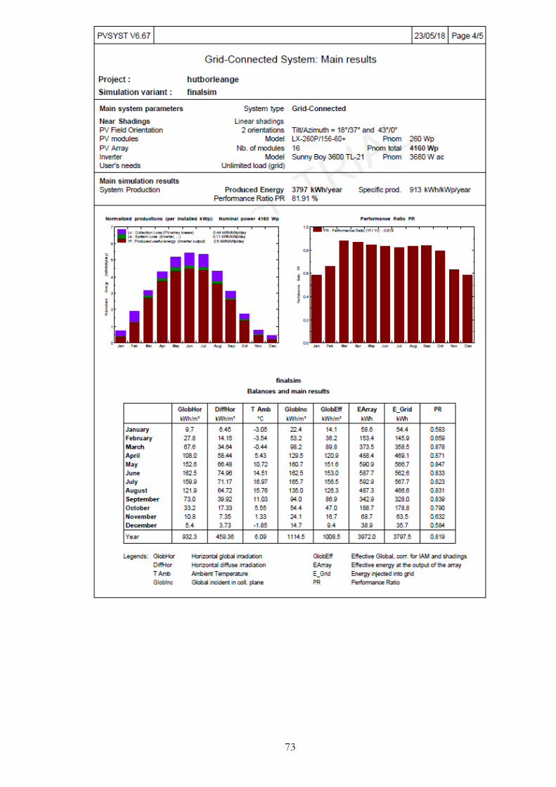
73

74

75
Appendix E: Questionnaire for PV Installation Companies