master specifications division 25 … specifications division 25 – integrated automation and hvac...
TRANSCRIPT
MASTER SPECIFICATIONS
Division 25 – INTEGRATED AUTOMATION AND HVAC
CONTROL
Release 1.0 [March] 2017 Released by: Northwestern University Facilities Management Operations 2020 Ridge Avenue, Suite 200 Evanston, IL 60208-4301
All information within this Document is considered CONFIDENTIAL and PROPRIETARY. By receipt and use of this Document, the recipient agrees not to divulge any of the information herein and attached hereto to persons other than those within the recipients’ organization that have specific need to know for the purposes of reviewing and referencing this information. Recipient also agrees not to use this information in any manner detrimental to the interests of Northwestern University.

Northwestern University
Master Specifications
Copyright © 2017
By Northwestern University
These Specifications, or parts thereof, may not be reproduced in any form without
the permission of the Northwestern University.

NORTHWESTERN UNIVERSITY PROJECT NAME ____________ FOR: ___________ JOB # ________ ISSUED: 03/29/2017
MASTER SPECIFICATIONS: DIVISION 25 – INTEGRATED AUTOMATION AND HVAC CONTROL
SECTION # TITLE
25 0000 INTEGRATED AUTOMATION AND HVAC TEMPERATURE CONTROL 25 0800 COMMISSIONING OF INTEGRATED AUTOMATION
** End of List **

NORTHWESTERN UNIVERSITY PROJECT NAME ____________ FOR: ___________ JOB # ________ ISSUED: 03/29/2017
INTEGRATED AUTOMATION 25 0000 - 1
SECTION 25 0000 - INTEGRATED AUTOMATION AND HVAC TEMPERATURE CONTROL
PART 1 - GENERAL
1.1 SUMMARY AND RESPONSIBILITIES
A. The work covered under this Division 25 of the project specifications is basically for:
1. Providing fully functioning facility/project HVAC system DDC controls. 2. Controlling systems locally, with communication up to the Tridium integration platform for
remote monitoring, trending, control, troubleshooting and adjustment by NU Engineering and Maintenance personnel.
3. Tying specified systems to the Northwestern University (NU) integration platform for remote monitoring, trending, control, management, troubleshooting and adjustment by NU Engineering and Maintenance personnel.
4. The Division 25 controls contractor to (subcontractor to the GC and also referred to herein as the DDC/BASC Contractor) provide a complete DDC Control and Building Automation system, which interfaces with the NU Tridium Integration platform through the University’s Ethernet infrastructure.. The Owners' normal day to day interface will be with the Tridium system. The configuration of graphics, trends, alarms, etc. for the Tridium system will be done by the System Integrator. [For this project, the System Integrator is to be hired by the University/General Contractor/Commissioning Authority, as determined during project design and finalized herein this section by the project AE. See Section 1.4]. The Division 25 Contractor is responsible for coordinating with the System Integrator to verify all points are properly integrated into the Tridium platform including alarm values and links to trend files. The Division 25 contractor is to provide sufficient manpower to work with the System Integrator to do a point to point test of alarms, trending, setpoint overrides, etc. Electric meters have static IP addresses. The SCADA system integrates with the electric meters through the static IP addresses, over NUIT infrastructure. Any communication between SCADA and BAS is done at the server level.
B. Related Sections
1. Section 25 0800 “Commissioning of Integrated Automation.”
1.2 PURPOSE OF THIS DOCUMENT
A. The purpose of this document is to describe, and assign responsibility for, the Integration Automation and DDC/BASC control systems at Northwestern University, to define the roles of the System Integrator and the Division 25 Contractor, and to describe the work required for the DDC control and Integrated Automation on this project.
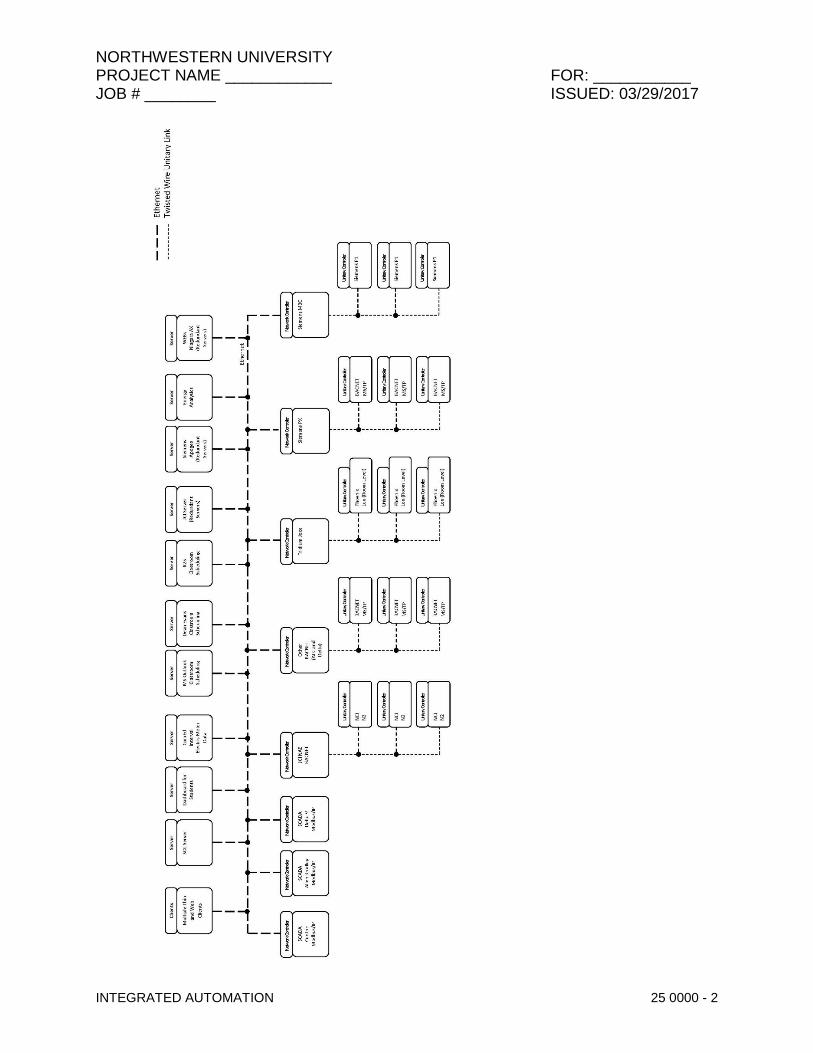
B. The Enterprise Server consists of the Honeywell Tridium WebsAX running on three Stratus EverRun redundant servers. Two servers are located on the Evanston Campus, and one server is located on the Chicago Campus. Both the JCI and Siemens head end servers currently reside on this redundant server.
C. The Figure on the next page shows a simple schematic of the NU Cloud based Automation Integration System. All Ethernet is NUIT.
NORTHWESTERN UNIVERSITY PROJECT NAME ____________ FOR: ___________ JOB # ________ ISSUED: 03/29/2017
INTEGRATED AUTOMATION 25 0000 - 2

NORTHWESTERN UNIVERSITY PROJECT NAME ____________ FOR: ___________ JOB # ________ ISSUED: 03/29/2017
INTEGRATED AUTOMATION 25 0000 - 3
1.3 ROLE OF THE BUILDING AUTOMATION SYSTEM CONTRACTOR (BASC):
A. All panels and devices shall be configured to utilize static IP addresses. These shall be provided by Owner, and are not to be assigned by the BASC. This process is to be managed through the project’s NU PM.
B. All BACNET instance numbers for network controllers shall be provided by the Owner, and are not to be assigned by the BASC. Instance numbers will utilize the vendor BACNET ID as the first digit(s).
C. BASC is to coordinate all third party BACNET devices with the vendor and Owner. These devices shall communicate to a local BASC panel, BACNET MS/TP is preferred. BACNET IP communication protocols shall be approved by Owner on a case-by-case basis only.
D. All systems are to be set up for a static BBMD, not dynamic.
E. Owner (specifically the DDC shop on the respective campus) shall be notified prior to any device or panel being brought online.
F. Provide the field devices and wiring including DDC controllers, relays, sensors, transducers, control devices, control panels, controller programming, controller programming software, controller input/output and power wiring and controller network wiring to provide a complete working system of the mechanical equipment.
G. Submittals: Provide an electronic copy of the specification sheets for the equipment and DDC controls being provided for the specific project. The drawings shall be drawn in Visio or AutoCAD, and shall include separate sections for the following: index page, a riser diagram, flow diagrams, panel detail, wiring schematics, termination of controllers, full points list including any global or virtual points, any valve schedules and damper schedules.
H. Use the Northwestern University DDC Standard document for point naming structure (see PART 4 herein).
I. Provide as-built drawings and O&M Manuals in electronic form (Visio or MS Word or Adobe pdf format).
J. Provide Network Controllers as required for a project. Coordinate quantity and locations of new network controller with Owner and System Integrator. Acceptable network controllers are manufactured by Siemens, Honeywell Jace, Johnson Controls, Delta Controls, and Automated Logic Corporation.
K. Network Controllers:
1. Johnson Controls:
a. Communication to field control devices shall be through BACNET MS/TP, not JCI N2.
2. Siemens Controls:
a. Provide most current Apogee controller compatible with the existing Siemens campus infrastructure. PXC Modular is preferred to PXC Compact.
b. Communications to field control devices shall be through BACNET MS/TP.
NORTHWESTERN UNIVERSITY PROJECT NAME ____________ FOR: ___________ JOB # ________ ISSUED: 03/29/2017
INTEGRATED AUTOMATION 25 0000 - 4
3. Honeywell Tridium (Honeywell is not approved for field control. It is to be used for integration of devices only):
a. Northwestern University has standardized on the Honeywell WEB-600-O-US NiagaraAX™ Controller, to follow a consistent standard of design and operation supporting overall system conformance standards. Other branded NiagaraAX™ network controllers are unacceptable.
b. All network controller hardware products shall be “Made in the USA” or come through the Tridium Richmond, Virginia shipping facility.
c. All network controllers shall include a lifetime license for free software upgrades. d. The network controllers shall be provided with no connectivity restrictions on which
brand stations or tools can interact with the system. The station and tool “NiCS” would be as follows:

NORTHWESTERN UNIVERSITY PROJECT NAME ____________ FOR: ___________ JOB # ________ ISSUED: 03/29/2017
INTEGRATED AUTOMATION 25 0000 - 5
Property Value
STATION COMPATIBILITY IN ALL
STATION COMPATIBILITY OUT ALL
TOOL COMPATIBILITY IN ALL
TOOL COMPATIBILITY OUT ALL
4. Delta Controls:
a. Northwestern University does not have a standard developed for Delta Controls at the time of publication.
b. Communications to field control devices shall be through BACNET MS/TP.
5. Automated Logic
a. Provide most current controller compatible with existing ALC campus infrastructure. b. Communications to field control devices shall be through BACNET MS/TP.
L. Point to point checkout with documentation.
M. Verify all physical alarms.
N. Setup alarms in the network controller in accordance with the Northwestern University DDC Standards document. Coordinate with Owner on alarm distribution. Work with the SI to make sure the NU Cloud is receiving the alarms.
O. Setup trends in the BASC’s associated server in accordance with the Northwestern University DDC Standards document. Work with the SI to make sure the Enterprise Server is receiving the trends.
P. Accessing controllers via PCAnywhere, Telnet or similar software is not allowed. Remote access shall be through Northwestern’s SSLVPN.
Q. Any software required for controller configuration shall be included as a leave-behind tool with enough license capability to support the installation. Provide the appropriate quantity of legal copies of all software tools, configuration tools, management tools, and utilities used during system commissioning and installation. All tools shall be generally available in the market. No closed and/or unavailable tools will be permitted. Contractor shall convey all software tools and their legal licenses at project close out.
1.4 Role of the System Integrator (Separate Contract and Cannot Be The Same Contractor as the BASC [For this project, the System Integrator is to be hired by the University/General Contractor/Commissioning Authority, as determined during project design and finalized herein this section by the project AE]. ):
A. The System Integrator (SI), Engineer, Owner and selected Building Automation System Contractor (BASC) meet to review the project so that all programming, design standards and job specific requirements are consistent with the NU DDC Standards (see PART 4).

NORTHWESTERN UNIVERSITY PROJECT NAME ____________ FOR: ___________ JOB # ________ ISSUED: 03/29/2017
INTEGRATED AUTOMATION 25 0000 - 6
B. Coordinate with the BASC to ensure point discovery and integration is scheduled at appropriate times during construction.
C. The SI shall be responsible to build/create the graphic layout/background slides in conformance with the Northwestern University DDC Standards document (see PART 4). The graphics shall be resident on the Enterprise Server.
D. Maintain point naming structure. Verify BASC is adhering to the naming convention.
E. Submittals: Sample graphics, list of trend and alarm points and parameters.
F. Coordinate with the BASC to verify proper alarm input to the NU Cloud, and display on the graphics.
G. Coordinate with the BASC to verify proper link to the trend files on the NU Cloud graphics.
H. Setup event log.
I. Merge project O&M documents, including the control drawings, into a common system O&M manual.
J. Work with the Owners IT Department to establish I/P network addresses with BACnet instance IDs and ensure the appropriate I/P addresses with BACnet instance IDs are used throughout the BAS.
1.5 REFERENCES
A. General: Reference NU Direct Digital Control (DDC) Standards for reference to Northwestern University Standards for Building Automation (BAS), Building Management Systems (BMS), Automatic Temperature Control (ATC) standards including control diagrams, sequences and equipment.
B. The publications listed below form a part of this specification to the extent referenced. The publications are referred to in the text by the basic designation only.
AIR MOVEMENT AND CONTROL ASSOCIATION INTERNATIONAL (AMCA)
AMCA 500-D (2007) Laboratory Methods of Testing Dampers for Rating
AMERICAN SOCIETY OF HEATING, REFRIGERATING AND AIR-CONDITIONING ENGINEERS (ASHRAE)
ASHRAE 90.1 ASHRAE 135
(2007) Energy Standard for Buildings Except Low-Rise Residential Buildings (2010; INT 1-3 2011; Addenda AD & AE 2011; Errata 2012) BACnet—A Data Communication Protocol for Building Automation and Control Networks
ARCNET TRADE ASSOCIATION (ATA)
ATA 878.1 (1999) Local Area Network: Token Bus

NORTHWESTERN UNIVERSITY PROJECT NAME ____________ FOR: ___________ JOB # ________ ISSUED: 03/29/2017
INTEGRATED AUTOMATION 25 0000 - 7
ASME INTERNATIONAL (ASME)
ASME B16.18 (2012) Cast Copper Alloy Solder Joint Pressure Fittings
ASME B16.22 (2001; R 2010) Standard for Wrought Copper and Copper Alloy Solder Joint Pressure Fittings
ASME B16.26 (2011) Standard for Cast Copper Alloy Fittings for Flared Copper Tubes
ASME B16.34 (2009; Supp 2010) Valves - Flanged, Threaded and Welding End
ASME B16.5 (2009) Pipe Flanges and Flanged Fittings: NPS 1/2 Through NPS 24 Met-ric/Inch Standard
ASME B31.1 (2010) Power Piping
ASME B40.100 (2005; R 2010) Pressure Gauges and Gauge Attachments
ASME BPVC (2010) Boiler and Pressure Vessels Code ASTM INTERNATIONAL (ASTM)
ASTM A126 (2004; R 2009) Standard Specification for Gray Iron Castings for Valves, Flanges, and Pipe Fittings
ASTM B117 (2011) Standard Practice for Operating Salt Spray (Fog) Apparatus
ASTM B32 (2008) Standard Specification for Solder Metal
ASTM B75 (2002; R 2010) Standard Specification for Seamless Copper Tube
ASTM B88 (2009) Standard Specification for Seamless Copper Water Tube
ASTM B88M (2005; R 2011) Standard Specification for Seamless Copper Water Tube (Met-ric)
ASTM D1238 (2010) Melt Flow Rates of Thermoplastics by Extrusion Plastometer
ASTM D1693 (2008) Standard Test Method for Environmental Stress-Cracking of Ethylene Plastics
ASTM D635 (2010) Standard Test Method for Rate of Burning and/or Extent and Time of Burning of Self-Supporting Plastics in a Horizontal Position
ASTM D638 (2010) Standard Test Method for Tensile Properties of Plastics
ASTM D792 (2008) Density and Specific Gravity (Relative Density) of Plastics by Displace-ment
CONSUMER ELECTRONICS ASSOCIATION (CEA)
CEA-709.1-C (2010) Control Network Protocol Specification
INSTITUTE OF ELECTRICAL AND ELECTRONICS ENGINEERS (IEEE)
IEEE C57.13 (2008) Standard Requirements for Instrument Transformers
IEEE C62.41.1 (2002; R 2008) Guide on the Surges Environment in Low-Voltage (1000 V and Less) AC Power Circuits
IEEE C62.41.2 (2002) Recommended Practice on Characterization of Surges in Low-Voltage (1000 V and Less) AC Power Circuits
NORTHWESTERN UNIVERSITY PROJECT NAME ____________ FOR: ___________ JOB # ________ ISSUED: 03/29/2017
INTEGRATED AUTOMATION 25 0000 - 8
IEEE C62.45 (2002; R 2008) Recommended Practice on Surge Testing for Equipment Con-nected to Low-Voltage (1000v and less)AC Power Circuits
INTERNATIONAL ORGANIZATION FOR STANDARDIZATION (ISO)
ISO 8802-3 (2000) Information Technology - Telecommunications and Information Ex-change Between Systems - Local and Metropolitan Area Networks - Specific Requirements - Part 3: Carrier Sense Multiple Access with Collision Detection (CSMA/CD)Access Method and Physical Layer Specifications
NATIONAL ELECTRICAL MANUFACTURERS ASSOCIATION (NEMA)
NEMA/ANSI C12.10
(2011) Physical Aspects of Watthour Meters- Safety Standards
NATIONAL FIRE PROTECTION ASSOCIATION (NFPA)
NFPA 70 (2011; Errata 2 2012) National Electrical Code
NFPA 72 (2010; TIA 10-4) National Fire Alarm and Signaling Code
NFPA 90A (2012) Standard for the Installation of Air Conditioning and Ventilating Systems
SHEET METAL AND AIR CONDITIONING CONTRACTORS' NATIONAL ASSOCIATION (SMACNA)
SMACNA 1966 (2005) HVAC Duct Construction Standards Metal and Flexible, 3rd Edition
UNDERWRITERS LABORATORIES (UL)
UL 1449 (2006; Reprint Feb 2011) Surge Protective Devices
UL 506 (2008; Reprint Mar 2010) Specialty Transformers
UL 508A (2001; Reprint Feb 2010) Industrial Control Panels
UL 916 (2007; Reprint Jun 2010) Standard for Energy Management Equipment
1.6 DEFINITIONS
A. Algorithm: A logical procedure for solving a recurrent mathematical problem. A prescribed set of well-defined rules or processes for solving a problem in a finite number of steps.
B. Analog: A continuously varying signal value, such as current, flow, pressure, or temperature.
C. ANSI/ASHRAE Standard 135
1. ANSI/ASHRAE Standard 135: BACnet - A Data Communication Protocol for Building Automation and Control Networks, referred to as "BACnet". ASHRAE developed BACnet to provide a method for diverse building automation devices to communicate and share data over a network.
D. ARCNET

NORTHWESTERN UNIVERSITY PROJECT NAME ____________ FOR: ___________ JOB # ________ ISSUED: 03/29/2017
INTEGRATED AUTOMATION 25 0000 - 9
1. ATA 878.1 - Attached Resource Computer Network. ARCNET is a deterministic LAN technology; meaning it's possible to determine the maximum delay before a device is able to transmit a message.
E. BACnet
1. Building Automation and Control Network; the common name for the communication standard ASHRAE 135. The standard defines methods and protocol for cooperating building automation devices to communicate over a variety of LAN technologies.
F. BACnet/IP
1. An extension of BACnet, Annex J, defines this mechanism using a reserved UDP socket to transmit BACnet messages over IP networks. A BACnet/IP network is a collection of one or more IP sub-networks that share the same BACnet network number. See also "BACnet Broadcast Management Device".
G. BACnet Internetwork
1. Two or more BACnet networks, possibly using different LAN technologies, connected with routers. In a BACnet internetwork, there exists only one message path between devices.
H. BACnet Network
1. One or more BACnet segments that have the same network address and are interconnected by bridges at the physical and data link layers.
I. BACnet Segment
1. One or more physical segments of BACnet devices on a BACnet network, connected at the physical layer by repeaters.
J. BBMD
1. BACnet Broadcast Management Device (BBMD). A communications device typically combined with a BACnet router. A BBMD forwards BACnet broadcast messages to BACnet/IP devices and other BBMDs connected to the same BACnet/IP network. Every IP sub-network that is part of a BACnet/IP network must have only one BBMD. See also "BACnet/IP".
K. Binary: Two-state signal where a high signal level represents ON" or "OPEN" condition and a low signal level represents "OFF" or "CLOSED" condition. "Digital" is sometimes used interchangeably with "Binary" to indicate a two-state signal.
L. Building Control Appliance (BCA)
1. The Building Control Appliance (BCA) local operator interface is served as a web page
from the JACE. The BCA contains all the standard backgrounds, graphic standards and naming conventions utilized by the Systems Integrator during programming.
M. BIBBs
NORTHWESTERN UNIVERSITY PROJECT NAME ____________ FOR: ___________ JOB # ________ ISSUED: 03/29/2017
INTEGRATED AUTOMATION 25 0000 - 10
1. BACnet Interoperability Building Blocks. A collection of BACnet services used to describe supported tasks. BIBBs are often described in terms of "A" (client) and "B" (server) devices. The “A” device uses data provided by the "B" device, or requests an action from the “B” device.
N. BI
1. BACnet International, formerly two organizations: the BACnet Manufacturers Association
(BMA) and the BACnet Interest Group - North America (BIG-NA).
O. BI/BTL
1. BACnet International/BACnet Testing Laboratories (Formerly BMA/BTL). The organization responsible for testing products for compliance with the BACnet standard, operated under the direction of BACnet International.
P. Bridge
1. Network hardware that connects two or more network (or BACnet internetwork) segments at the physical and data link layers. A bridge may also filter messages.
Q. Broadcast
1. A message sent to all devices on a network segment.
R. Controller: Generic term for any standalone, microprocessor-based, digital controller residing on a network, used for local or global control. Three types of controllers are indicated: Network Controller, Programmable Application Controller, and Application-Specific Controller.
S. Control System Integrator: An entity that assists in expansion of existing enterprise system and support of additional operator interfaces to I/O being added to existing enterprise system.
T. COV: Changes of value.
U. Device
1. Any control system component, usually a digital controller that contains a BACnet Device
Object and uses BACnet to communicate with other devices. See also "Digital Controller".
V. Device Object
1. Every BACnet device requires one Device Object, whose properties represent the network visible properties of that device.
2. Every Device Object requires a unique Object Identifier number on the BACnet internetwork. This number is often referred to as the device instance.
W. Device Profile
1. A collection of BIBBs determining minimum BACnet capabilities of a device, defined in ASHRAE Standard 135-2004, Annex L.
2. Standard device profiles include BACnet Operator Workstations (B-OWS), BACnet
Building Controllers (B-BC), BACnet Advanced Application Controllers (B-AAC), BACnet

NORTHWESTERN UNIVERSITY PROJECT NAME ____________ FOR: ___________ JOB # ________ ISSUED: 03/29/2017
INTEGRATED AUTOMATION 25 0000 - 11
Application Specific Controllers (B-ASC), BACnet Smart Actuator (B-SA), and BACnet Smart Sensor (B-SS).
3. Each device used in new construction is required to have a PICS statement listing BIBBs supported.
X. Digital Controller
1. An electronic controller, usually with internal programming logic and digital and analog input/output capability, which performs control functions. In most cases, synonymous with a BACnet device described in this specification.
2. See also "Device".
Y. Direct Digital Control (DDC)
1. Digital controllers performing control logic. 2. Usually the controller directly senses physical values, makes control decisions with internal
programs, and outputs control signals to directly operate switches, valves, dampers, and motor controllers.
Z. DDC System
1. A network of digital controllers, communication architecture, and user interfaces. A DDC system may include programming, sensors, actuators, switches, relays, factory controls, operator workstations, and various other devices, components, and attributes.
AA. DDC System Provider: Authorized representative of, and trained by, DDC system manufacturer and responsible for execution of DDC system Work indicated.
BB. Distributed Control: Processing of system data is decentralized and control decisions are made at subsystem level. System operational programs and information are provided to remote subsystems and status is reported back. On loss of communication, subsystems shall be capable of operating in a standalone mode using the last best available data.
CC. DOCSIS: Data-Over Cable Service Interface Specifications.
DD. Ethernet
1. A family of local-area-network technologies providing high-speed networking features over various media.
EE. Firmware
1. Software programmed into read only memory (ROM), flash memory, electrically erasable programmable read only memory (EEPROM), or erasable programmable read only memory (EPROM) chips.
FF. Gateway
1. Communication hardware connecting two or more different protocols, similar to human language translators.
2. The Gateway translates one protocol into equivalent concepts for the other protocol. 3. In BACnet applications, a gateway has BACnet on one side and non-BACnet (usually
proprietary) protocols on the other side.

NORTHWESTERN UNIVERSITY PROJECT NAME ____________ FOR: ___________ JOB # ________ ISSUED: 03/29/2017
INTEGRATED AUTOMATION 25 0000 - 12
GG. HLC: Heavy load conditions.
HH. Half Router
1. A device that participates as one partner in a BACnet point-to-point (PTP) connection. 2. Two half-routers in an active PTP connection combine to form a single router.
II. Hub
1. A common connection point for devices on a network.
JJ. Internet Protocol (IP, TCP/IP, UDP/IP)
1. A communication method, the most common use is the World Wide Web. 2. At the lowest level, it is based on Internet Protocol (IP), a method for conveying and routing
packets of information over various LAN media. 3. Two common protocols using IP are User Datagram Protocol (UDP) and Transmission
Control Protocol (TCP). UDP conveys information to well-known "sockets" without
confirmation of receipt. TCP establishes "sessions", which have end-to-end confirmation
and guaranteed sequence of delivery.
KK. I/O: System through which information is received and transmitted. I/O refers to analog input (AI), binary input (BI), analog output (AO) and binary output (BO). Analog signals are continuous and represent control influences such as flow, level, moisture, pressure, and temperature. Binary signals convert electronic signals to digital pulses (values) and generally represent two-position operating and alarm status. "Digital," (DI and (DO), is sometimes used interchangeably with "Binary," (BI) and (BO), respectively. Physical inputs and outputs to and from a device, although the term sometimes describes software, or "virtual" I/O. See also "Points".
LL. I/O Expansion Unit
1. An I/O expansion unit provides additional point capacity to a digital controller.
MM. IP subnet
1. Internet protocol (IP) identifies individual devices with a 32-bit number divided into four groups from 0 to 255.
2. Devices are often grouped and share some portion of this number. For example, one device has IP address 209.185.47.68 and another device has IP address 209.185.47.82. These two devices share Class C subnet 209.185.47.00
NN. Java Application Control Engine (JACE)
1. All JACEs shall communicate to a web based server application by Ethernet connection over a dedicated Local Area Network (LAN) as coordinated and approved by Owner IT
2. All JACEs shall communicate to all controlled or monitored equipment in a building utilizing pulse signals, digital and analog inputs and outputs via BACnet™ on IP networks and/or local serial network connections.
OO. Local-Area Network (LAN)

NORTHWESTERN UNIVERSITY PROJECT NAME ____________ FOR: ___________ JOB # ________ ISSUED: 03/29/2017
INTEGRATED AUTOMATION 25 0000 - 13
1. A communication network that spans a limited geographic area and uses the same basic communication technology throughout.
PP. LNS: LonWorks Network Services.
QQ. LON Specific Definitions:
1. FTT-10: Echelon Transmitter-Free Topology Transceiver. 2. LonMark: Association comprising suppliers and installers of LonTalk products.
Association provides guidelines for implementing LonTalk protocol to ensure interoperability through a standard or consistent implementation.
3. LonTalk: An open standard protocol developed by the Echelon Corporation that uses a "Neuron Chip" for communication. LonTalk is a register trademark of Echelon.
4. LonWorks: Network technology developed by Echelon. 5. Node: Device that communicates using CEA-709.1-C protocol and that is connected to a
CEA-709.1-C network. 6. Node Address: The logical address of a node on the network, consisting of a Domain
number, Subnet number, and Node number. "Node number" portion of an address is a number assigned to device during installation, is unique within a subnet, and is not a factory-set unique Node ID.
7. Node ID: A unique 48-bit identifier assigned at factory to each CEA-709.1-C device. Sometimes called a "Neuron ID."
8. Program ID: An identifier (number) stored in a device (usually EEPROM) that identifies node manufacturer, functionality of device (application and sequence), transceiver used, and intended device usage.
9. Standard Configuration Property Type (SCPT): Pronounced "skip-it." A standard format type maintained by LonMark International for configuration properties.
10. Standard Network Variable Type (SNVT): Pronounced "snivet." A standard format type maintained by LonMark used to define data information transmitted and received by individual nodes. "SNVT" is used in two ways. It is an acronym for "Standard Network Variable Type" and is often used to indicate a network variable itself (i.e., it can mean "a network variable of a standard network variable type").
11. Subnet: Consists of a logical grouping of up to 127 nodes, where logical grouping is defined by node addressing. Each subnet is assigned a number, which is unique within a Domain. See "Node Address."
12. TP/FT-10: Free Topology Twisted Pair network defined by CEA-709.3 and is most common media type for a CEA-709.1-C control network.
13. TP/XF-1250: High-speed, 1.25-Mbps, twisted-pair, doubly terminated bus network defined by "LonMark Interoperability Guidelines" typically used only to connect multiple TP/FT-10 networks.
14. User-Defined Configuration Property Type (UCPT): Pronounced "U-Keep-It." A Configuration Property format type that is defined by device manufacturer.
15. User-Defined Network Variable Type (UNVT): Network variable format defined by device manufacturer. UNVTs create non-standard communications that other vendors' devices may not correctly interpret and may negatively impact system operation. UNVTs are not allowed.
RR. Low Voltage: As defined in NFPA 70 for circuits and equipment operating at less than 50 V or for remote-control, signaling power-limited circuits.
SS. MAC Address
1. Media Access Control address. 2. The physical node address that identifies a device on a Local Area Network.
NORTHWESTERN UNIVERSITY PROJECT NAME ____________ FOR: ___________ JOB # ________ ISSUED: 03/29/2017
INTEGRATED AUTOMATION 25 0000 - 14
TT. Master-Slave/Token-Passing (MS/TP)
1. ISO 8802-3. One of the LAN options for BACnet.
2. MS/TP uses twisted-pair wiring for relatively low speed and low cost communication (up to 4,000 ft at 76.8K bps).
UU. Modbus TCP/IP: An open protocol for exchange of process data.
VV. Native BACnet Device
1. A device that uses BACnet as its primary, if not only, method of communication with other BACnet devices without intermediary gateways.
2. A system that uses native BACnet devices at all levels is a native BACnet system.
WW. Network
1. Communication technology for data communications. BACnet approved network types are BACnet over Internet Protocol (IP), Point to Point (PTP) Ethernet, ARCNET, MS/TP, and LonTalk®.
XX. Network Controller: Digital controller, which supports a family of programmable application controllers and application-specific controllers that communicates on peer-to-peer network for transmission of global data.
YY. Network Number
1. A site-specific number assigned to each network segment to identify for routing. 2. This network number must be unique throughout the BACnet internetwork.
ZZ. Network Repeater: Device that receives data packet from one network and rebroadcasts it to another network. No routing information is added to protocol.
AAA. Object
1. The concept of organizing BACnet information into standard components with various associated properties. Examples include analog input objects and binary output objects.
BBB. Object Identifier
1. An object property used to identify the object, including object type and instance. Object Identifiers must be unique within a device.
CCC. Object Properties
1. Attributes of an object. Examples include present value and high limit properties of an analog input object.
2. Properties are defined in ASHRAE 135; some are optional and some are required. Objects are controlled by reading from and writing to object properties.
DDD. Owner

NORTHWESTERN UNIVERSITY PROJECT NAME ____________ FOR: ___________ JOB # ________ ISSUED: 03/29/2017
INTEGRATED AUTOMATION 25 0000 - 15
1. Owner - IRG, Industrial Reality Group
EEE. PDA: Personal digital assistant.
FFF. Peer-to-Peer
1. Peer-to-peer refers to devices where any device can initiate and respond to communication with other devices.
GGG. Performance Verification Test (PVT)
1. The procedure for determining if the installed system meets design criteria prior to final acceptance. The PVT is performed after installation, testing, and balancing of mechanical systems. Typically the PVT is performed by the Contractor in the presence of the Engineer.
HHH. PID
1. Proportional, integral, and derivative control; three parameters used to control modulating equipment to maintain a setpoint. Derivative control is often not required for HVAC systems (leaving "PI" control).
III. PICS
1. Protocol Implementation Conformance Statement (PICS), describing the BACnet capabilities of a device. See BACnet, Annex A for the standard format and content of a PICS statement.
JJJ. Points
1. Physical and virtual inputs and outputs. See also "Input/Output".
KKK. POT: Portable operator's terminal.
LLL. PTP
1. Point-to-Point protocol connects individual BACnet devices or networks using serial connections like modem-to-modem links.
MMM. PVT
1. Performance Verification Testing
NNN. RAM: Random access memory.
OOO. Repeater
1. A network component that connects two or more physical segments at the physical layer.
PPP. RF: Radio frequency.
QQQ. Router

NORTHWESTERN UNIVERSITY PROJECT NAME ____________ FOR: ___________ JOB # ________ ISSUED: 03/29/2017
INTEGRATED AUTOMATION 25 0000 - 16
1. A BACnet router is a component that joins together two or more networks using different LAN technologies. Examples include joining a BACnet Ethernet LAN to a BACnet MS/TP LAN.
RRR. Stand-Alone Control
1. Refers to devices performing equipment-specific and small system control without communication to other devices or computers for physical I/O, excluding outside air and other common shared conditions.
2. Devices are located near controlled equipment, with physical input and output points limited to 64 or less per device, except for complex individual equipment or systems.
3. Failure of any single device will not cause other network devices to fail.
4. BACnet "Smart" actuators (B-SA profile) and sensors (B-SS profile) communicating on a network with a parent device are exempt from stand-alone requirements.
SSS. TCP/IP: Transport control protocol/Internet protocol incorporated into Microsoft Windows.
TTT. UPS: Uninterruptible power supply.
UUU. USB: Universal Serial Bus.
VVV. User Datagram Protocol (UDP): This protocol assumes that the IP is used as the underlying protocol.
WWW. VAV: Variable air volume.
XXX. WLED: White light emitting diode.
1.7 LIBRARY
A. A standard library of objects shall be included for development and setup of application logic, user interface displays, system services, and communication networks.
B. The objects in this library shall be capable of being copied and pasted into the user's database and shall be organized according to their function. In addition, the user shall have the capability to group objects created in their application and store the new instances of these objects in a user-defined library.
C. In addition to the standard libraries specified here, the supplier of the system shall maintain an on-line accessible (over -the Internet) library, available to all registered users to provide new or updated objects and applications as they are developed.
D. All control objects shall conform to the control objects specified in the BACnet specification.
E. The library shall include applications or objects for the following functions, at a minimum: 1. Scheduling Object. The schedule must conform to the schedule object as defined in the
BACnet specification, providing 7-day plus holiday & temporary scheduling features and a minimum of 10 on/off events per day. Data entry to be by graphical sliders to speed creation and selection of on-off events.

NORTHWESTERN UNIVERSITY PROJECT NAME ____________ FOR: ___________ JOB # ________ ISSUED: 03/29/2017
INTEGRATED AUTOMATION 25 0000 - 17
2. Calendar Object. The calendar must conform to the calendar object as defined in the BACnet specification, providing 12-month calendar features to allow for holiday or special event data entry. Data entry to be by graphical "point-and-click" selection. This object must be "linkable" to any or all scheduling objects for effective event control.
3. Duty Cycling Object. Provide a universal duty cycle object to allow repetitive on/off time control of equipment as an energy conserving measure. Any number of these objects may be created to control equipment at varying intervals
4. Temperature Override Object. Provide a temperature override object that is capable of overriding equipment turned off by other energy saving programs (scheduling, duty cycling etc.) to maintain occupant comfort or for equipment freeze protection.
5. Start-Stop Time Optimization Object. Provide a start-stop time optimization object to provide the capability of starting equipment just early enough to bring space conditions to desired conditions by the scheduled occupancy time. Also, allow equipment to be stopped before the scheduled un-occupancy time just far enough ahead to take advantage of the building's "flywheel" effect for energy savings. Provide automatic tuning of all start/stop time object properties based on the previous day's performance.
6. Demand Limiting Object. Provide a comprehensive demand-limiting object that is capable of controlling demand for any selected energy utility (electric, oil, and gas). The object shall provide the capability of monitoring a demand value and predicting (by use of a sliding window prediction algorithm) the demand at the end of the user defined interval Period (1-60 minutes). This object shall also accommodate a utility meter time sync pulse for fixed interval demand control. Upon a prediction that will exceed the user defined demand limit (supply a minimum of 6 per day), the demand limiting object shall issue shed commands to either turn off user specified loads or modify equipment set points to effect the desired energy reduction. If the list of sheddable equipment is not enough to reduce the demand to below the set point, a message shall be displayed on the users screen (as an alarm) instructing the user to take manual actions to maintain the desired demand. The shed lists are specified by the user and shall be selectable to be shed in either a fixed or rotating order to control which equipment is shed the most often. Upon suitable reductions in demand, the demand-limiting object shall restore the equipment that was shed in the reverse order in which it was shed. Each sheddable object shall have a minimum and maximum shed time property to effect both equipment protection and occupant comfort.
F. The library shall include control objects for the following functions. All control objects shall conform to the objects as specified in the BACnet specification. 1. Analog Input Object - Minimum requirement is to comply with the BACnet standard for data
sharing. Allow high, low and failure limits to be assigned for alarming. Also, provide a time delay filter property to prevent nuisance alarms caused by temporary excursions above or below the user defined alarm limits.
2. Analog Output Object - Minimum requirement is to comply with the BACnet standard for data sharing.
3. Binary Input Object - Minimum requirement is to comply with the BACnet standard for data sharing. The user must be able to specify either input condition for alarming. This object must also include the capability to record equipment run-time by counting the amount of time the hardware input is in an "on" condition. The user must be able to specify either input condition as the "on" condition.
4. Binary Output Object - Minimum requirement is to comply with the BACnet standard for data sharing. Properties to enable minimum on and off times for equipment protection as well as interstart delay must be provided. The BACnet Command Prioritization priority scheme shall be incorporated to allow multiple control applications to execute commands on this object with the highest priority command being invoked. Provide sixteen levels of priority as a minimum. Systems not employing the BACnet method of contention resolution shall not be acceptable.

NORTHWESTERN UNIVERSITY PROJECT NAME ____________ FOR: ___________ JOB # ________ ISSUED: 03/29/2017
INTEGRATED AUTOMATION 25 0000 - 18
5. PID Control Loop Object - Minimum requirement is to comply with the BACnet standard for data sharing. Each individual property must be adjustable as well as to be disabled to allow proportional control only, or proportional with integral control, as well as proportional, integral and derivative control.
6. Comparison Object- Allow a minimum of two analog objects to be compared to select either the highest, lowest, or equality between the two linked inputs. Also, allow limits to be applied to the output value for alarm generation.
7. Math Object - Allow a minimum of four analog objects to be tested for the minimum or maximum, or the sum, difference, or average of linked objects. Also, allow limits to be applied to the output value for alarm generation.
8. Custom Programming Objects - Provide a blank object template for the creation of new custom objects to meet specific user application requirements. This object must provide a simple BASIC-like programming language that is used to define object behavior. Provide a library of functions including math and logic functions, string manipulation, and e-mail as a minimum. Also, provide a comprehensive on-line debug tool to allow complete testing of the new object. Allow new objects to be stored in the library for re-use.
9. Interlock Object - Provide an interlock object that provides a means of coordination of objects within a piece of equipment such as an Air Handler or other similar types of equipment. An example is to link the return fan to the supply fan such that when the supply fan is started, the return fan object is also started automatically without the user having to issue separate commands or to link each object to a schedule object. In addition, the control loops, damper objects, and alarm monitoring (such as return air, supply air, and mixed air temperature objects) will be inhibited from alarming during a user-defined period after startup to allow for stabilization. When the air handler is stopped, the interlocked return fan is also stopped, the outside air damper is closed, and other related objects within the air handler unit are inhibited from alarming thereby eliminating nuisance alarms during the off period.
10. Temperature Override Object - Provide an object whose purpose is to provide the capability of overriding a binary output to an "On" state in the event a user specified high or low limit value is exceeded. This object is to be linked to the desired binary output object as well as to an analog object for temperature monitoring, to cause the override to be enabled. This object will execute a Start command at the Temperature Override level of start/stop command priority unless changed by the user.
11. Composite Object - Provide a container object that allows a collection of objects representing an application to be encapsulated to protect the application from tampering, or to more easily represent large applications. This object must have the ability to allow the user to select the appropriate parameters of the "contained" application that are represented on the graphical shell of this container.
1.8 DIRECT DIGITAL CONTROL SYSTEMS FOR HVAC DESCRIPTION
Design Requirements
A. Control System Drawings Title Sheet
1. Provide a title sheet for the control system drawing set. 2. Include the project title, project location, contract number, the controls contractor preparing
the drawings, an index of the control drawings in the set, and a legend of the symbols and abbreviations used throughout the control system drawings.
B. List of I/O Points
NORTHWESTERN UNIVERSITY PROJECT NAME ____________ FOR: ___________ JOB # ________ ISSUED: 03/29/2017
INTEGRATED AUTOMATION 25 0000 - 19
1. Also known as a Point Schedule, provide for each input and output point physically connected to a digital controller: a. Point name, Point description, Point type (Analog Output (AO), Analog Input (AI),
Binary Output (BO), Binary Input (BI)), point sensor range, point actuator range, point address, BACnet object, associated BIBBS (where applicable), and point connection terminal number.
b. Typical schedules for multiple identical equipment components are allowed unless otherwise requested in design or contract criteria.
C. Control System Components List
1. Provide a complete list of control system components installed on this project. a. Include for each controller and device: control system schematic name, control
system schematic designation, device description, manufacturer, and manufacturer part number.
b. For sensors, include point name, sensor range, and operating limits. c. For valves, include body style, Cv, design flow rate, pressure drop, valve
characteristic (linear or equal percentage), and pipe connection size. d. For actuators, include point name, spring or non-spring return, modulating or two-
position action, normal (power fail) position, nominal control signal operating range (0-10 volts DC or 4-20 milliamps), and operating limits.
D. Control System Schematics
1. Provide control system schematics. 2. Typical schematics for multiple identical equipment items are allowed unless otherwise
requested in design or contract criteria. Include the following: a. Location of each input and output device b. Flow diagram for each piece of HVAC equipment c. Name or symbol for each control system component, such as V-1 for a valve d. Setpoints, with differential or proportional band values e. Written sequence of operation for the HVAC equipment f. Valve and Damper Schedules, with normal (power fail) position
E. HVAC Equipment Electrical Ladder Diagrams
1. Provide HVAC equipment electrical ladder diagrams. Indicate required electrical interlocks.
F. Component Wiring Diagrams
1. Provide a wiring diagram for each type of input device and output device. Indicate how each device is wired and powered; showing typical connections at the digital controller and power supply. Show for all field connected devices such as control relays, motor starters, actuators, sensors, and transmitters.
G. Terminal Strip Diagrams
1. Provide a diagram of each terminal strip. Indicate the terminal strip location, termination numbers, and associated point names.
H. Communication Architecture Schematic
1. Provide a schematic showing the project's entire communication network, including addressing used for LANs, LAN devices including JACE’s, routers and bridges, gateways,

NORTHWESTERN UNIVERSITY PROJECT NAME ____________ FOR: ___________ JOB # ________ ISSUED: 03/29/2017
INTEGRATED AUTOMATION 25 0000 - 20
controllers, workstations, and field interface devices. If applicable, show connection to existing networks.
I. Web based server application as provided in this specification shall be based on a hierarchical architecture incorporating the Niagara AX Framework™. Equivalent products must be approved in writing by the Owner/Engineer and be submitted for approval ten (10) days prior to the date of the bid submittal. Systems not developed on the Niagara AX Framework™ platform are unacceptable. 1. The web based server application shall monitor and control equipment as called for by the
“sequence of operation” and points list. a. Home page to include a minimum of six critical points, i.e. Outside Air Temperature,
Outside Air Relative Humidity, Enthalpy, KWH, KW etc. The owner will clarify the critical points during the base project graphical interface design phase.
b. Graphic floor plans accurately depicting rooms, walls, hallways, and showing accurate locations of space sensors and major mechanical equipment, including thermostats and CO2 sensors. Space temperatures and CO2 readings are to be reported and updated on the graphic floor plans.
c. Detailed graphics for each mechanical and electrical system to include; VAV boxes, perimeter radiation, cabinet unit heaters, thermostats, boilers, pumps, chillers, air handler and associated variable frequency drives, exhaust fans, and domestic water heaters.
J. SUBMITTALS
1. Submit detailed and annotated manufacturer's data, drawings, and specification sheets for each item listed, that clearly show compliance with the project specifications.
2. Shop Drawings Include the following in the project's control system drawing set: a. Control system drawings title sheet b. List of I/O Points c. Control System Components List d. Control system schematics e. HVAC Equipment Electrical Ladder diagrams f. Component wiring diagrams g. Terminal strip diagrams h. BACnet communication architecture schematic i. Sequence of Operation
3. Product Data
a. Direct Digital Controllers
1) Include BACnet PICS for each controller/device type, including smart sensors
(B-SS) and smart actuators (B-SA).
b. BACnet Gateways 1) Include BACnet and workstation display information; bi-directional
communication ability; compliance with interoperability schedule; expansion capacity; handling of alarms, events, scheduling and trend data; and single device capability (not depending on multiple devices for exchanging information from either side of the gateway).

NORTHWESTERN UNIVERSITY PROJECT NAME ____________ FOR: ___________ JOB # ________ ISSUED: 03/29/2017
INTEGRATED AUTOMATION 25 0000 - 21
c. BACnet Protocol Analyzer 1) Include capability to store and report data traffic on BACnet networks,
measure bandwidth usage, filter information, and identify BACnet devices.
d. DDC Software e. BACnet Operator Workstation DDC Software
1) Include BACnet PICS for Operator Workstation software. f. Notebook Computer with appropriate software for Maintenance Department g. Sensors and Input Hardware h. Output Hardware i. Surge and transient protection j. Indicators k. Design Data l. Performance Verification Testing Plan m. Pre-Performance Verification Testing Checklist - Test Reports n. Performance Verification Testing Report - Certificates o. Contractor's Qualifications p. Manufacturer's Field Reports q. Pre-PVT Checklist r. Operation and Maintenance Data s. Controls System Operators Manuals t. Closeout Submittals u. Training documentation
K. The System Integrator shall provide an unlimited data point license of energy analytics software. The license shall be applied to each JACE installed or utilized on this project.
L. The System Integrator shall provide automated alarming software capable of sending messages to email compatible cellular telephones and pagers via the owner's e-mail service. The email alarm paging system shall be able to segregate users, time schedules, and equipment, and be capable of being programmed by the owner.
M. Any dedicated configuration tool required for controller configuration shall have the capability to be launched from within the applicable Network Management Software. If the configuration tool(s) cannot be launched from the Network Management Software, any software required for controller configuration shall be included as a leave-behind tool with full licensing to the owner. All JACE's shall be provided with preinstalled "Workbench".
N. The contractor shall provide the appropriate quantity of legal copies of all software tools, configuration tools, management tools, and utilities used during system commissioning and installation. All tools shall be generally available in the market. No closed and/or unavailable tools will be permitted. Contractor shall convey all software tools and their legal licenses to the Owner at project close out.
1.9 SOFTWARE LICENSE AGREEMENT
A. The Owner shall agree to the manufacturer's standard software and firmware licensing agreement as a condition of this contract. Such license shall grant use of all programs and application software to Owner as defined by the manufacturer's license agreement, but shall protect manufacturer's rights to disclosure of trade secrets contained within such software.

NORTHWESTERN UNIVERSITY PROJECT NAME ____________ FOR: ___________ JOB # ________ ISSUED: 03/29/2017
INTEGRATED AUTOMATION 25 0000 - 22
B. The Owner shall be the named license holder of all software associated with any and all incremental work on the project(s). In addition, the Owner shall receive ownership of all job specific configuration documentation, data files, and application-level software developed for the project. This shall include all custom, job specific software code and documentation for all configuration and programming that is generated for a given project and/or configured for use with the web based server application and JACE's, and any related LAN/WAN/Intranet and Internet connected routers and devices. Any and all required IDs and passwords for access to any component or software program shall be provided to the owner.
C. The owner shall receive ownership of all job specific software configuration documentation, data files, and application-level software developed for the project. This shall include all custom, job specific software code and documentation for all configuration and programming that is generated for a given project and /or configured for use within Niagara AX Framework based controllers and/or servers and any related LAN/WAN/Intranet and all connected routers and devices.
D. Software licensing for the JACE and server software shall give the Owner the capability to control their system and determine which contractors can bid and engineer their system.
E. It shall be possible to insure the Owner can prevent unauthorized partners from accessing the system for engineering changes.
F. Software licensing shall have the freedom to individually manage authorized parties and independent parties.
G. The software licensing shall have no restrictions on which brand of server software or System Programming tools can interact with the system. Station Compatibility must = ALL and Tool Compatibility must= ALL.
H. All JACE's shall be of an Open license type. The license shall never expire.
1.10 QUALITY ASSURANCE
A. If anything listed herein cannot be met, then all exceptions taken are to be included with the bid.
B. Provide with bid, detailed description describing how system temperatures and pressures are calculated. Refer to sequence of operation.
C. Provide with bid any and all licensing requirements.
D. Pre-Submittal Meeting
1. DDC System contractor shall convene a pre-submittal meeting with the engineer, commissioning agent and owner within one month of the notice to proceed. The purpose of this meeting is to review the sequences of operation, outline where the proposed system deviates from the specified sequence of operation, and identify potential problems with the specified sequence. Once the sequences of operation are agreed to by all parties, the contractor shall proceed with the formal controls submittal process. DDC System contractor shall submit a print out of all graphics proposed for the project within one month following submittal approval for review jointly by the owner, engineer, and commissioning agent. DDC System Contractor will be required to demonstrate the prescribed operations while in the Owners office. The Owner, Engineer, Construction Manager, Commissioning Agent and Mechanical Contractor may be present to observe and evaluate the
NORTHWESTERN UNIVERSITY PROJECT NAME ____________ FOR: ___________ JOB # ________ ISSUED: 03/29/2017
INTEGRATED AUTOMATION 25 0000 - 23
demonstration. In order to meet the specification and be considered acceptable they must meet these requirements.
2. The following items will be reviewed during the demonstration:
a. Access to the system through a standard web browser, Internet Explorer. b. Ease-of-use of the system relating to:
1) Changing Schedules 2) Changing Set Points 3) Modifying Program Logic 4) Modifying Graphics 5) Reviewing Historical Trends 6) Downloading Controllers 7) Review Activity Log 8) Review / Edit / Acknowledge Alarms 9) Programming remote alarms to cell phones and email
E. Standard Products
1. Provide material and equipment that are standard manufacturer's products currently in production and supported by a local service organization.
F. Delivery, Storage, and Handling
1. Handle, store, and protect equipment and materials to prevent damage before and during installation according to manufacturer's recommendations.
2. Replace damaged or defective items.
G. Operating Environment
1. Protect components from humidity and temperature variation, dust, and contaminants.
2. If components are stored before installation, keep them within the manufacturer's limits.
H. Finish of New Equipment
1. New equipment finishing shall be factory provided.
2. Manufacturer's standard factory finishing shall be proven to withstand 125 hours in a salt-spray fog test. a. Equipment located outdoors shall be proven to withstand 500 hours in a salt-spray
fog test. b. Salt-spray fog test shall be according to ASTM B117, with acceptance criteria as
follows: immediately after completion of the test, the finish shall show no signs of
degradation or loss of adhesion beyond 3.175 mm 0.125 inch on either side of the
scratch mark.
I. Verification of Dimensions
1. The contractor shall verify all dimensions in the field, and advise the Construction Manager
of any discrepancy before performing work.
J. Contractor's Qualifications

NORTHWESTERN UNIVERSITY PROJECT NAME ____________ FOR: ___________ JOB # ________ ISSUED: 03/29/2017
INTEGRATED AUTOMATION 25 0000 - 24
1. Submit documentation certifying the controls Contractor performing the work has completed at least three DDC systems installations of a similar design to this project, and programmed similar sequences of operation for at least two years.
2. All bidders must have a minimum of three (3), installed, web-based systems. Systems must be accessible via the Internet from the Owners office and shall be able to demonstrate these systems, prior to award of contract, using only an Owner provided web browser.
K. Project Sequence - The control system work for this project shall proceed in the following order:
1. Submit and receive approval on the Shop Drawings, Product Data, and Certificates specified under the paragraph entitled "SUBMITTALS."
2. Perform the control system installation work, including all field check-outs and tuning.
3. Provide support to TAB personnel as specified under the paragraph "TEST AND BALANCE SUPPORT."
4. Provide support to Commissioning Agent
5. Submit and receive approval of the Controls System Operators Manual specified under the paragraph "CONTROLS SYSTEM OPERATORS MANUALS."
6. Submit and receive approval of the Performance Verification Testing Plan and the Pre-PVT Checklist specified under the paragraph "PERFORMANCE VERIFICATION TESTING."
7. Perform the Performance Verification Testing.
8. Submit and receive approval on the PVT Report.
9. Provide one year trend data
10. Submit and receive approval on the Training Documentation at least 30 days before training.
11. Deliver the final Controls System Operators Manuals.
12. Conduct the Phase I Training.
13. Conduct the Phase II Training.
14. Submit and receive approval of Closeout Submittals
L. Control systems shall meet the requirements of ASHRAE Standard 90.1.
1.11 COORDINATION
A. Coordinate location of thermostats, room humidity sensors, CO2 sensors, and other exposed control sensors with plans and room details before installation.
B. Coordinate equipment with Section 28 3113 "Digital Addressable Fire detection and Alarm Systems" to achieve compatibility with equipment that interfaces with that system.

NORTHWESTERN UNIVERSITY PROJECT NAME ____________ FOR: ___________ JOB # ________ ISSUED: 03/29/2017
INTEGRATED AUTOMATION 25 0000 - 25
C. Coordinate equipment with Section 26 2416 "Panelboards" to achieve compatibility with starter coils and annunciation devices.
D. Coordinate equipment with Division 26 Section “Lighting Controls” to achieve compatibility with lighting control system.
E. Coordinate supply of conditioned electrical branch circuits for control units and operator workstation.
F. Coordinate size and location of concrete bases. Cast anchor-bolt inserts into bases. Concrete, reinforcement, and formwork requirements are specified in Division 3 "Cast-in-Place Concrete" section.
G. DDC System Contractor shall furnish and install:
1. A fully integrated BACnet building automation system, UL listed, incorporating direct digital control (DDC) for energy management, equipment monitoring and control.
2. Necessary conduit, wiring, enclosures, and panels, for all DDC temperature control equipment and devices. Installation shall comply with applicable local and national codes.
3. All components and control devices necessary to provide a complete and operable DDC system as specified herein.
4. All conduit and wiring for power to all DDC System devices, including but not limited to: 120 Volt, 24 Volts AC, 24 Volts DC, etc.
5. DDC System Contractor shall be responsible for all electrical work associated with the DDC System and as called for on the Drawings. This DDC System control wiring shall be furnished and installed in accordance with the Electrical requirements as specified in Division 26, the National Electric Code, and all applicable local codes.
6. DDC System Contractor shall provide programming modifications necessary to fine tune sequences during commissioning and through warranty period of systems at no additional cost.
7. DDC System Contractor shall be responsible for furnishing and installing all relays and contactors required for the building lighting control. Coordinate lighting control components with the Electrical Contractor to form an integrated interconnection of compatible components. a. Match components and interconnections for optimum performance of lighting control
functions. b. Display graphics showing building areas controlled; include the status of lighting
controls in each area.
H. Mechanical Contractor provides:
1. All wells and openings for water and air monitoring devices, temperature sensors, flow switches and alarms furnished by DDC System Contractor.
2. Installation of all control valves furnished by DDC System Contractor.
3. Installation of control dampers external to air handling units furnished by DDC System Contractor, and adjacent access doors for smoke; outdoor air, return air, exhaust air.
NORTHWESTERN UNIVERSITY PROJECT NAME ____________ FOR: ___________ JOB # ________ ISSUED: 03/29/2017
INTEGRATED AUTOMATION 25 0000 - 26
I. Electrical Contractor provides:
1. Electrical Contractor shall provide dedicated 120 volt, 20 amp circuits and circuit breakers from normal and/or emergency power panel for each Direct Digital Controller. Run power circuit within 5 feet of equipment installed and connected by DDC System Contractor.
2. Wall mounted junction box and conduit to ceiling space for all room temperature sensors, relative humidity sensors and Carbon Dioxide sensors.
3. Electrical Contractor shall furnish and install all lighting and lighting sensors and control devices per section 26 09 23 Lighting Control Devices, 26 51 00 Interior Lighting and 26 56 00 Exterior Lighting. Electrical Contractor shall furnish and install all line voltage wiring thru the contracts as furnished and installed by the DDC System Contractor.
1.12 WARRANTY
A. One (1) year manufacturer's warranty on all DDC control system components from universal warranty start date defined in front end documents.
1.13 PRE-INSTALLATION MEETINGS
A. Pre-installation Conference: Conduct conference at Project site. Attendees required are to be: BASC, SI, A/E, NU DDC.
PART 2 - PRODUCTS
2.1 DDC SYSTEM (OPEN, INTEROPERABLE, INTEGRATED ARCHITECTURE)
A. The intent of this specification is to provide a peer-to-peer networked, stand- alone, distributed control system with the capability to integrate ANSI/ASHRAETM Standard 135-2001 BACnet™, LonWorks™ technology, MODBUS ™, OPC, and other open and proprietary communication protocols into one open, interoperable system.
B. Adherence to industry standards including ANSI/ASHRAETM Standard 135-2001, BACnet and LonMark to assure interoperability between all system components is required. For each LonWorks device that does not have a LonMark certification, the device supplier must provide an XIF file and a resource file for the device. For each BACnet device, the device supplier must provide a PICS document showing the installed device's compliance level. Minimum compliance is Level 3; with the ability to support data read and write functionality. Physical connection of BACnet devices shall be via Ethernet (BACnet Ethernet/IP,) and/or RS-485 (BACnet MSTP) as specified.
C. All components and controllers supplied under contract shall be true "peer-to-peer" communicating devices. Components or controllers requiring "polling" by a host to pass data shall not be acceptable without the consent of the Owner or Engineer.
D. The supplied system must incorporate the ability to access all data using standard Web browsers without requiring proprietary operator interface and configuration programs. Systems requiring proprietary database and user interface programs shall not be acceptable.

NORTHWESTERN UNIVERSITY PROJECT NAME ____________ FOR: ___________ JOB # ________ ISSUED: 03/29/2017
INTEGRATED AUTOMATION 25 0000 - 27
E. A hierarchical topology is required to assure reasonable system response times and to manage the flow and sharing of data without unduly burdening the customer's internal Intranet network. Systems employing a "flat" single tiered architecture shall not be acceptable. 1. Maximum acceptable response time from any alarm occurrence (at the point of origin) to
the point of annunciation shall not exceed 5 seconds for local network connected user interfaces.
2.2 ADVANCED UNITARY CONTROLLER
A. The controller platform shall be designed specifically to control HVAC – ventilation, filtration, heating, cooling, humidification, and distribution. Equipment includes: constant volume air handlers, VAV air handlers, air cooled chillers, hot water boilers, pumps, HVAC split systems, unit vents, fan coils, natural convection units, radiant panels and all other heating and cooling devices. The controller platform shall provide options and advanced system functions, programmable and configurable using Niagara AX Framework™, that allow standard and customizable control solutions required in executing the "Sequence of Operation".
B. Minimum Requirements: 1. The controller shall be capable of either integrating with other devices or stand-alone
operation. 2. The controller shall have two microprocessors. The Host processor contains on-chip
FLASH program memory, FLASH information memory, and RAM to run the main HVAC application. The second processor for BACnet® network communications. a. FLASH Memory Capacity: 372 Kilobytes with 8 Kilobytes for application program. b. FLASH Memory settings retained for ten years. c. RAM: 8 Kilobytes
3. The controller shall have an internal time clock with the ability to automatically revert from a master time clock on failure. a. Operating Range: 24 hour, 365 day, multi-year calendar including day of week and
configuration for automatic day-light savings time adjustment to occur on configured start and stop dates.
b. Accuracy: ±1 minute per month at 77° F (25° C). c. Power Failure Backup: 24 hours at 32° to 100° F (0° to 38° C), 22 hours at 100° to
122° F (38° to 50° C). 4. The controller shall have an internal DC power supply to power external sensors. 5. The controller shall have a visual indication (LED) of the status of the device. 6. The controller shall have a visual indication (LED) of the BACnet MS/TP communication
status of the device: a. Processor missing bootloader image. b. Bootloader running and no MS/TP token present. c. Bootloader running and there is MS/TP communication. d. BACnet communications processor is not running.
7. The minimum controller Environmental ratings: a. Operating Temperature Ambient Rating: -40° to 150° F (-40° to 65.5° C). b. Storage Temperature Ambient Rating: -40° to 150° F (-40° to 65.5° C). c. Relative Humidity: 5% to 95% non-condensing.
8. The controller shall have the additional approval requirements, listings, and approvals: a. UL/cUL (E87741) listed under UL916 (Standard for Open Energy Management
Equipment) with plenum rating. b. BACnet Application Specific Controller (B-ASC) c. CSA (LR95329-3) Listed
9. The controller housing shall be UL plenum rated mounting to either a panel or DIN rail (standard EN50022; 7.5mm x 35mm).

NORTHWESTERN UNIVERSITY PROJECT NAME ____________ FOR: ___________ JOB # ________ ISSUED: 03/29/2017
INTEGRATED AUTOMATION 25 0000 - 28
10. The controller shall have sufficient on-board inputs and outputs to support the application. a. Analog outputs (AO) shall be capable of being configured to support 0-10 V, 2-10 V
or 4-20 mA devices. b. Triac outputs shall be capable of switching 30 Volts at 500 mA.
11. The controller shall provide "continuous" automated loop tuning with an Adaptive Integral Algorithm Control Loop.
12. The controller: platform shall have standard HVAC application programs that are modifiable to support both the traditional and specialized "sequence of operations". a. Discharge air control and low limit. b. Pressure-dependent dual duct without flow mixing. c. Variable air volume with return flow tracking. d. Economizer with differential enthalpy. e. Minimum air flow coordinated with CO2. f. Unit ventilator cycle - 2-pipe. g. Unit ventilator cycle - 2-pipe with face/bypass.
2.3 WEB BROWSER CLIENTS
A. The system shall be capable of supporting an unlimited number of clients using a standard Web browser such as Internet Explorer™ or Mozilla Firefox™. Systems requiring additional software (to enable a standard Web browser) to be resident on the client machine, or manufacture-specific browsers shall not be acceptable.
B. Web browser software shall run on any operating system and system configuration that is supported by the Web browser. Systems that require specific machine requirements in terms of processor speed, memory, etc., in order to allow the Web browser to function with the BMS, shall not be acceptable.
C. The Web browser shall provide the same view of the system, in terms of graphics, schedules, calendars, logs, etc., and provide the same interface methodology as is provided by the Graphical User Interface (if used). Systems that require different graphic views, different means of graphic generation, or that require different means of interacting with objects such as schedules, or logs, shall not be permitted.
D. The Web browser client shall support at a minimum, the following functions: 1. User log-on identification and password shall be required. If and unauthorized user
attempts access, a blank web page shall be displayed. Security using Java authentication and encryption techniques to prevent unauthorized access shall be implemented.
2. Graphical screens developed for the BCA shall be the same screens used for the Web browser client.
3. HTML programming shall not be required to display system graphics or data on a Web page. HTML editing of the Web page shall be allowed if the user desires a specific look or format.
4. Storage of the graphical screens shall be in the web based server application. 5. Real-time values displayed on a Web page shall update automatically without requiring a
manual "refresh" of the Web page. 6. Users shall have administrator-defined access privileges. Depending on the access
privileges assigned, the user shall be able to perform the following: a. Modify common application objects, such as schedules, calendars, and set points in
a graphical manner. 1) Schedule times will be adjusted using a graphical slider, without requiring any
keyboard entry from the operator.

NORTHWESTERN UNIVERSITY PROJECT NAME ____________ FOR: ___________ JOB # ________ ISSUED: 03/29/2017
INTEGRATED AUTOMATION 25 0000 - 29
2) Holidays shall be set by using a graphical calendar, without requiring any keyboard entry from the operator.
b. Commands to start and stop binary objects shall be done by right-clicking the selected object and selecting the appropriate command from the pop-up menu. No text entry shall be required.
c. View logs and charts d. View and acknowledge alarms e. Setup and execute SQL queries on log and archive information
7. The system shall provide the capability to specify a user's (as determined by the log-on user identification) home page. Provide the ability to set a specific home page for each user. From the home page, links to other views, or pages in the system shall be possible, if allowed by the system administrator.
8. Graphic screens on the Web Browser client shall support hypertext links to other locations on the Internet or on Intranet sites, by specifying the Uniform Resource Locator (URL) for the desired link
2.4 DDC CONTROL SYSTEM EQUIPMENT
A. MANUFACTURERS
1. Manufacturers: Subject to compliance with requirements, provide products by one of the manufacturers specified.
a. Johnson Controls. b. Siemens. c. Delta. d. Automated Logic Corporation
B. Control system shall consist of sensors, indicators, actuators, final control elements, interface equipment, other apparatus, and accessories to control mechanical systems.
C. Control system shall consist of sensors, indicators, actuators, final control elements, interface equipment, other apparatus, accessories, and software connected to distributed controllers operating in multiuser, multitasking environment on token-passing network and programmed to control mechanical systems. An operator workstation permits interface with the network via dynamic color graphics with each mechanical system, building floor plan, and control device depicted by point-and-click graphics.
D. All temperature control wiring shall be provided for a complete and operable system. All wiring shall be installed in accordance with Division 26, NEC and all local Codes.
E. The Controls Contractor will be responsible for all system graphics software, graphic creation, alarming as specified, scheduling as specified and, shall train the Owner on how to set-up alarms, trending and scheduling.
F. Control systems shall meet the requirements of ASHRAE Standard 90.1.
G. Direct Digital Controllers
1. Direct digital controllers shall be UL 916 rated.
H. I/O Point Limitation

NORTHWESTERN UNIVERSITY PROJECT NAME ____________ FOR: ___________ JOB # ________ ISSUED: 03/29/2017
INTEGRATED AUTOMATION 25 0000 - 30
1. The total number of I/O hardware points used by a single stand-alone digital controller, including I/O expansion units, shall not exceed 64, except for complex individual equipment or systems.
2. Place I/O expansion units in the same cabinet as the digital controller.
I. Environmental Limits
1. Controllers shall be suitable for, or placed in protective enclosures suitable for the environment (temperature, humidity, dust, and vibration) where they are located.
J. Stand-Alone Control
1. Provide stand-alone digital controllers.
K. Internal Clock
1. Provide internal clocks for all BACnet Building Controllers (B-BC) and BACnet Advanced
Application Controllers (B-AAC) using BACnet time synchronization services. a. Automatically synchronize system clocks daily from an operator-designated
controller. b. The system shall automatically adjust for daylight saving time.
L. Memory
1. Provide sufficient memory for each controller to support the required control, communication, trends, alarms, and messages. a. Protect programs residing in memory with EEPROM, flash memory, or by an
uninterruptible power source (battery or uninterruptible power supply). b. The backup power source shall have capacity to maintain the memory during a 72-
hour continuous power outage. c. Rechargeable power sources shall be constantly charged while the controller is
operating under normal line power. Batteries shall be replaceable without soldering. d. Trend and alarm history collected during normal operation shall not be lost during
power outages less than 72 hours long.
M. Immunity to Power Fluctuations
1. Controllers shall operate at 90 percent to 110 percent nominal voltage rating.
N. Transformer
1. The controller power supply shall be fused or current limiting and rated at 125 percent
power consumption.
O. Wiring Terminations
1. Use screw terminal wiring terminations for all field-installed controllers. a. Provide field-removable modular terminal strip or a termination card connected by a
ribbon cable for all controllers other than terminal units.
P. Input and Output Interface
1. Provide hard-wired input and output interface for all controllers as follows:
NORTHWESTERN UNIVERSITY PROJECT NAME ____________ FOR: ___________ JOB # ________ ISSUED: 03/29/2017
INTEGRATED AUTOMATION 25 0000 - 31
a. Protection: Shorting an input or output point to itself, to another point, or to ground shall cause no controller damage. Input or output point contact with sources up to 24 volts AC or DC for any duration shall cause no controller damage.
b. Binary Inputs: Binary inputs shall monitor on and off contacts from a "dry" remote device without external power, and external 5-24 VDC voltage inputs.
c. Pulse Accumulation Inputs: Pulse accumulation inputs shall conform to binary input requirements and accumulate pulses at a resolution suitable to the application.
d. Analog Inputs: Analog inputs shall monitor low-voltage (0-10 VDC), current (4-20 mA), or resistance (thermistor or RTD) signals.
e. Binary Outputs: Binary outputs shall send a pulsed 24 VDC low-voltage signal for modulation control, or provide a maintained open-closed position for on-off control.
f. Analog Outputs: Analog outputs shall send modulating 0-10 VDC or 4-20 mA signals to control output devices.
g. Tri-State Outputs: Tri-State outputs shall provide three-point floating control of terminal unit electronic actuators.
Q. Digital Controller BACnet Internetwork
1. Provide a BACnet internetwork with control products, communication media, connectors, repeaters, hubs, and routers.
2. Provide intermediate gateways, only when requested by the Engineer and shown on the contract drawings, to connect existing non-BACnet devices to the BACnet internetwork. Controller and operator interface communication shall conform to ASHRAE 135, BACnet. If a controller becomes non-responsive, the remaining controllers shall continue operating and not be affected by the failed controller.
R. Communications Ports
1. Direct-Connect Interface Ports: a. Provide at least one extra communication port at each local BACnet network for
direct connecting a notebook computer or BACnet hand-held terminal so all network BACnet objects and properties may be viewed and edited by the operator.
2. Telecommunications Interface Port: a. Provide telephone communication port so that DDC System can send alarms to cell
phones.
S. BACnet Gateways
1. Provide BACnet communication ports, whenever available as a plant equipment OEM standard option, for DDC integration via a single communication cable. Typical BACnet controlled plant equipment includes, but is not limited to, boilers, chillers, and variable frequency motor drives.
2. Provide gateways only when specifically requested and approved by the Engineer, and shown on the Engineer approved BACnet Communication Architecture Schematic.
3. Provide with each gateway an interoperability schedule [Use gateway interoperability schedules shown on design drawings or other project documents], showing each point or event on the legacy side that the BACnet "client" will read, and each parameter that the BACnet network will write to.
4. Describe this interoperability in terms of BACnet services, or Interoperability Building Blocks (BIBBS), defined in ASHRAE 135 Annex K. Provide two-year minimum warranty for each gateway, including parts and labor.
5. The following minimum capabilities are required:
NORTHWESTERN UNIVERSITY PROJECT NAME ____________ FOR: ___________ JOB # ________ ISSUED: 03/29/2017
INTEGRATED AUTOMATION 25 0000 - 32
a. Gateways shall be able to read and view all readable object properties listed in the interoperability schedule on the non-BACnet network to the BACnet network and vice versa where applicable.
b. Gateways shall be able to write to all writeable object properties listed in the interoperability schedule on the non-BACnet network from the BACnet network and vice versa where applicable.
c. Gateways shall provide single-pass (only one protocol to BACnet without intermediary protocols) translation from the non-BACnet protocol to BACnet and vice versa.
d. Gateways shall meet the requirements of Data Sharing Read Property (DS-RP-B), Data Sharing Write Property (DS-WP-B), Device Management Dynamic Device Binding-B (DM-DDB-B), and Device Management Communication Control (DM-DCC-B) BIBBs, in accordance with ASHRAE 135.
e. Gateways shall include all hardware, software, software licenses, and configuration tools for operator-to-gateway communications.
6. Provide backup programming and parameters on CD media and the ability to modify, download, backup, and restore gateway configuration.
T. Digital Controller Cabinet
1. Provide each digital controller in a factory fabricated cabinet enclosure. a. Cabinets located indoors shall protect against dust and have a minimum NEMA 1
rating, except where indicated otherwise. b. Cabinets located outdoors or in damp environments shall protect against all outdoor
conditions and have a minimum NEMA 4 rating.
2. Outdoor control panels and controllers must be able to withstand extreme ambient conditions, without malfunction or failure, whether or not the controlled equipment is running.
3. If necessary, provide a thermostatically controlled panel heater in freezing locations, and an internal ventilating fan in locations exposed to direct sunlight. Cabinets shall have a hinged lockable door and an offset removable metal back plate, except controllers integral with terminal units, like those mounted on VAV boxes.
4. Provide like-keyed locks for all hinged panels provided and a set of two keys at each panel, with one key inserted in the lock.
U. Main Power Switch and Receptacle
1. Provide each control cabinet with a main external power on/off switch located inside the cabinet.
2. Also provide each cabinet with a separate 120 VAC duplex receptacle.
V. Lighting Control System 1. The lighting control “system” shall include a fully distributed WAN/LAN network of global
controller/routers, individually addressable I/O controllers, sensors, switches, relays and other ancillary devices required for a complete and operable system. The system WAN/LAN shall be designed, engineered, installed and commissioned by certified individuals.
2. The basis of system design shall utilize non-propriety industry standard dimming and non-dimming (0-10v) ballasts. No Systems using proprietary components may be utilized unless approved by the owner and engineer.
3. All proprietary items must be listed and highlighted on the submittal for the owner to review. Pricing shall be listed and guaranteed for 10 years.

NORTHWESTERN UNIVERSITY PROJECT NAME ____________ FOR: ___________ JOB # ________ ISSUED: 03/29/2017
INTEGRATED AUTOMATION 25 0000 - 33
4. Any changes to the control and/or power wiring vs. what is shown on the drawings shall be submitted by the contractor to the engineer, with all changes highlighted in an alternate color, and reviewed by the engineer.
5. On-going system expansion, service and support shall be available from multiple factory certified vendors. Recommended service agreements shall be submitted at the time of bid complete with manufacturers suggested inventory and pricing for system parts and technical support labor
6. Lighting Control: The System shall offer two separate levels, web based and PC interface: (1) personal lighting control for the average building occupant to control and adjust basic lighting functions in their workspace, and (2) central energy control for the lighting administrator to perform energy management, configuration maintenance, monitoring operations, and providing support to building occupants. a. Shall provide a Windows-based graphical user interface (GUI) showing floor plans
and lighting layouts. The lighting control system shall be programmed and operated from a user interface that is based in a plan view graphical screen on the user’s computer or the lighting control system main Controller. All assignments of lighting loads to control strategies shall be executed from this GUI and editing shall be available from this GUI in a drag and drop format or from drop down menus. The GUI shall continuously indicate the status of each connected device on the system and implement a pop up warning if a device goes offline. Systems requiring spreadsheet editing for programming and that don’t offer live feedback are not acceptable. Systems employing a non-Windows GUI shall be provided with a Windows environment overlay/emulator such that the software operates as close as possible to Windows. Costs for said overlay/emulator shall be included in the lighting control system pricing and shall be demonstrated and accepted by Owner prior to approval of submittals.
b. Central Control: Energy Control Software interface shall provide current status and enable configuration of all System zones including selected individual fixture availability, current light level, maximum light level, on/off status, occupancy status, and emergency mode status.
c. Reports: Energy performance reports shall be printable in a printer friendly format and downloadable for use in spreadsheet applications, etc.
d. Energy consumption and demand by strategy. e. Occupancy senor and daylight harvesting information. f. Personal Lighting Controls: The Personal Control Software interface shall provide
current status and enable each user with the ability to dim and brighten lights, and turn them on and off by individual fixture or zone. The Software shall offer user configurable light scenes, which may be programmed and then selected via the Software. Personal lighting control shall be available in open/private office environments.
7. Daylight Harvesting (Light Regulation Averaging): In a photo sensor-equipped System, the Energy Control Unit shall rationalize changes to light levels when ambient (natural) light is available and shall maintain a steady light level when subjected to fluctuating ambient conditions where dimming ballast exist. Areas with standard ballast shall energize when natural light falls below foot-candle level specified on drawings. System shall utilize light level inputs from common and/or remote sensor locations to minimize the number of photo sensors required. The System shall operate with multiple users in harmony and not react adversely to manual override inputs. Daylight harvesting shall not impede personal lighting control and the ability to adjust light levels on a per fixture basis. Daylight harvesting be capable of closed loop operation by the monitoring the combination of natural and artificial light within an area.
8. Time Clock Scheduling: The System shall be programmable for scheduling lights on or off via the Energy Control Software interface.

NORTHWESTERN UNIVERSITY PROJECT NAME ____________ FOR: ___________ JOB # ________ ISSUED: 03/29/2017
INTEGRATED AUTOMATION 25 0000 - 34
a. Override: manual adjustments and occupancy sensor detection shall temporarily override off status imposed by time clock schedule.
b. Response to Power Failure: In the event of a power failure, the time clock shall execute schedules that would still be in progress had they begun during the power outage.
c. Flick Warning: Two minutes prior to a scheduled lights-off event or expiry of a temporary override, the System shall provide two short light level drops as a warning to the affected occupants.
9. Load Shed Mode: An automatic load shedding mode shall be available where, when activated through the System, the control unit will reduce its output to a programmable maximum electrical demand load. The System shall not shed more load than required and load shedding priority shall be centrally configurable by light fixture. The individual user shall retain the ability to override the system thru web based personal control.
10. Emergency Mode: There shall be a mode, when activated through the System, that will immediately adjust EM lights to full light output and retain that level until the mode is deactivated. This setting shall override all other inputs. The System shall interface with the building emergency monitoring system at a convenient point and not require multiple connections.
11. Addressing: Fluorescent ballasts shall be centrally addressable, on a per fixture or multiple fixtures/zone basis, through the Energy Control Software. The basis of design shall utilize a single common I/O device to communicate to industry standard 0-10V dimming ballasts, although proprietary digitally addressable ballasts may be substituted providing they meet all the provisions of 2.2.D and 2.2.E. To simplify ongoing maintenance, the System shall not require manual recording of addresses for commissioning or reconfiguration. Provide a demonstration of what work is involved to reprogram System when a dimming ballast must be replaced. In the event that said work involves reprogramming of System in any manner for digital dimming ballasts, provide an extended service contract to cover the additional programming time for the 25% additional ballasts included as spares.
12. Programmable Task Tuning: Maximum light level programmability shall be available by individual fixture.
13. Unoccupied State: The System shall provide two states when occupancy status is vacant as per an occupancy sensor: lights turn off or lights adjust to configurable light level.
14. Occupied State: The System shall not isolate occupants by turning off lights that are still required for convenience and safety, such as a hallway path to exit the premises.
15. LAN Operations: System shall operate independently of building’s existing network infrastructure and shall not rely on tenant supplied PCs for operation. Network infrastructure shall only be utilized for Personal Control Software. Manufacturer must provide software to facilitate communications. Manufacturer shall provide connection from the PC running energy management and lighting control software to the System communication bus.
16. Firewall Security: System firewall technology shall maintain network security. 17. Low-Voltage Wiring: Prefabricated, quick connecting wiring shall be utilized. The maximum
connected length of wiring shall be no less than 1,500 feet per channel. 18. Lamp Burn In: The System shall not permit dimming of new lamps prior to completion of
manufacturer recommended 100 hour accumulated operation at full brightness. 19. Re-configurability: the assignment of individual fixtures to zones shall be centrally
configurable by Energy Control Software such that physical rewiring will not be necessary when workspace reconfiguration is performed. Removal of covers, faceplates, ceiling tiles, etc. shall not be required.
20. Automatic Control Parameters: Occupancy sensor time delays shall configurable through software. Light level senor parameters shall be configurable through software.
21. Expandability: System shall be capable of increasing the number of control functions in the future by 25 percent of current capacity; to include equipment ratings, housing capacities, spare relays, terminals, and control software.

NORTHWESTERN UNIVERSITY PROJECT NAME ____________ FOR: ___________ JOB # ________ ISSUED: 03/29/2017
INTEGRATED AUTOMATION 25 0000 - 35
22. Automatic Time Adjustment: System shall automatically adjust for leap year and daylight savings time and shall provide weekly routine and annual holiday scheduling.
23. Contact closure input: System shall be capable of receiving a momentary and sustained contact closure input from third party sources to control lighting zones.
2.5 DDC Software
A. Programming
1. Provide programming to execute the sequence of operation indicated. Provide all programming and tools to configure and program all controllers.
2. Provide programming routines in simple, easy-to-follow logic with detailed text comments describing what the logic does and how it corresponds to the project's written sequence of operation. a. Graphic-based programming shall use a library of function blocks made from pre-
programmed code designed for DDC SYSTEM control. Function blocks shall be assembled with interconnecting lines, depicting the control sequence in a flowchart. If providing a computer with device programming tools as part of the project, graphic programs shall be viewable in real time showing present values and logical results from each function block.
b. Menu-based programming shall be done by entering parameters, definitions, conditions, requirements, and constraints.
c. For line-by-line and text-based programming, declare variable types (local, global, real, integer, etc.) at the beginning of the program. Use descriptive comments frequently to describe the programming.
d. If providing a computer with device programming tools as part of the project, provide a means for detecting program errors and testing software strategies with a simulation tool.
3. Simulation may be inherent within the programming software suite, or provided by physical controllers mounted in a NEMA 1 test enclosure.
4. The test enclosure shall contain one dedicated controller of each type provided under this contract, complete with power supply and relevant accessories.
B. Parameter Modification
1. All writeable object properties, and all other programming parameters needed to comply with the project specification shall be adjustable for devices at any network level, including those accessible with web-browser communication, and regardless of programming methods used to create the applications.
C. Short Cycling Prevention
1. Provide setpoint differentials and minimum on/off times to prevent equipment short cycling.
D. Equipment Status Delay
1. Provide an adjustable delay from when equipment is commanded on or off and when the control program looks to the status input for confirmation.
E. Run Time Accumulation
NORTHWESTERN UNIVERSITY PROJECT NAME ____________ FOR: ___________ JOB # ________ ISSUED: 03/29/2017
INTEGRATED AUTOMATION 25 0000 - 36
1. Use the Elapsed Time Property to provide re-settable run time accumulation for each Binary Output Object connected to mechanical loads greater than 1 HP, electrical loads greater than 10 KW, or wherever else specified.
F. Timed Local Override
1. Provide an adjustable override time for each push of a timed local override button.
G. Time Synchronization
1. Provide time synchronization, including adjustments for leap years, daylight saving time, and operator time adjustments.
H. Scheduling
1. Provide operating schedules as indicated, with equipment assigned to groups. Changing the schedule of a group shall change the operating schedule of all equipment in the group. Groups shall be capable of operator creation, modification, and deletion.
2. Provide capability to view and modify schedules in a seven-day week format. 3. Provide capability to enter holiday and override schedules one full year at a time.
I. Object Property Override
1. Allow writeable object property values to accept overrides to any valid value. Where specified or required for the sequence of control, the Out-Of-Service property of Objects shall be modifiable using BACnet's write property service.
2. When documented, exceptions to these requirements are allowed for life, machine, and process safeties.
J. Alarms and Events
1. Alarms and events shall be capable of having programmed time delays and high-low limits. 2. When a computer workstation or web server is connected to the BACnet internetwork,
alarms/events shall report to the computer, printer, e-mail, cell phone, as defined by an authorized operator. Otherwise alarms/events shall be stored within a device on the BACnet network until connected to a user interface device and retrieved. Provide alarms/events in agreement with the point schedule, sequence of operation, and the DDC SYSTEM Owner.
3. At a minimum, provide programming to initiate alarms/events any time a piece of equipment fails to operate, a control point is outside normal range or condition shown on schedules, communication to a device is lost, a device has failed, or a controller has lost its memory.
K. Trending
1. Provide BACnet trend services capable of trending all object present values set points, and other parameters indicated for trending on project schedules. a. Trends may be associated into groups, and a trend report may be set up for each
group. b. Trends are stored within a device on the BACnet network, with operator selectable
trend intervals from 10 seconds up to 60 minutes. The minimum number of consecutive trend values stored at one time shall be 100 per variable.
c. When trend memory is full, the most recent data shall overwrite the oldest data.

NORTHWESTERN UNIVERSITY PROJECT NAME ____________ FOR: ___________ JOB # ________ ISSUED: 03/29/2017
INTEGRATED AUTOMATION 25 0000 - 37
d. The operator workstation shall upload trends automatically upon reaching 3/4 of the device buffer limit (via Notification Threshold property), by operator request, or by time schedule for archiving.
e. Archived and real-time trend data shall be available for viewing numerically and graphically for at the workstation and connected notebook computers.
L. Device Diagnostics
1. Each controller shall have diagnostic LEDs for power, communication, and device fault condition.
2. The DDC system shall recognize and report a non-responsive controller.
M. Power Loss
1. Upon restoration of power, the DDC system shall perform an orderly restart and restoration of control.
N. Lighting Control Programming 1. Control system software application used to commission, configure and manage the
system. Configuration of every system parameter in a building (or campus of buildings) for each individual user or space and establishes the baseline settings for the following system features: a. Daylight harvesting. b. Occupancy control. c. Smart time scheduling. d. Task tuning. e. Personal control. f. Load shedding
2.6 BACnet Operator Workstation (if specified by design)
A. The workstation shall be capable of accessing all DDC system devices and communicate using the BACnet protocol.
1. The workstation shall be capable of displaying, modifying, creating, archiving, and deleting (as applicable): all points, objects, object properties, programming, alarms, trends, messages, schedules, and reports.
B. DDC System Contractor shall determine if a server or host computer (not server rated) is to be utilized.
C. Computer with minimum; 1. Windows 7 Home Premium 64 bit 2. Intel Core I5-2320 Processor 3. 8 GigaByte DDR3 memory, 1333 MHz 4. Quantity 2, 1 TB Hard Drives, SATA-6, setup as RAID 1 5. CD/DVD Writer/Reader 6. Radeon HD 6450, 1GB DDR3 7. 23 inch widescreen LED monitor 8. 2 USB 3.0 ports 9. 10/100/1000 Ethernet 10. Standard Tower Case 11. 460 watt power supply

NORTHWESTERN UNIVERSITY PROJECT NAME ____________ FOR: ___________ JOB # ________ ISSUED: 03/29/2017
INTEGRATED AUTOMATION 25 0000 - 38
12. 2 TB backup portable hard drive, USB 3.0 interface. 13. Uninterruptable Power Supply
D. Password Protection
1. Provide at least five levels of password protection for operator interfaces. a. The lowest level only allow viewing graphics b. The second level allows viewing graphics and changing space temperature
setpoints. c. The third level allows the previous level's capability, plus changing operating
schedules. d. The fourth level allows access to all functions except passwords. e. The highest level provides all administrator rights and allows full access to all
programming, including setting new passwords and access levels.
2. Provide the Owner with the highest level password access. 3. Provide automatic log out if no keyboard or mouse activity is detected after a user-defined
time delay.
E. BACnet Operator Workstation DDC Software
1. Provide the workstation software with the manufacturer's installation CDs and licenses. Configure the software according to the DDC system manufacturer's specifications and in agreement with BACnet Operator Workstation (B-OWS) device standards found in ASHRAE 135, Annex L.
2. The workstation software shall permit complete monitoring, modification, and troubleshooting interface with the DDC system. a. The operator interface with the software shall be menu-driven with appropriate
displays and menu commands to manipulate the DDC system's objects, point data, operating schedules, control routines, system configuration, trends, alarms, messages, graphics, and reports.
b. Trends shall be capable of graphic display in real time, with variables plotted as functions of time. Each alarmed point shall be capable of displaying its alarm history, showing when it went into alarm, if and when it was acknowledged, and when it went out of alarm. The modification of DDC system parameters and object properties shall be accomplished with "fill in the blank" and/or "point and drag" methods. Modifications shall download to the appropriate controllers at the operator's request.
F. Graphics Software
1. Provide system graphics as dictated by latest DDC policy. 2. Graphic displays shall have full-screen resolution when viewed on the workstation and
notebook computers. a. Dynamic data on graphics pages shall refresh within 10 seconds using an Internet
connection, b. Graphics viewing shall not require additional "plug-in" software like Java,
Shockwave and Flash applications unless the software is readily available for free over the Internet.
3. The graphics shall show the present value and object name for each of the project's I/O points on at least one graphic page. a. Arrange point values and names on the graphic displays in their appropriate physical
locations with respect to the floor plan or equipment graphic displayed. Graphics shall allow the operator to monitor current status, view zone and equipment

NORTHWESTERN UNIVERSITY PROJECT NAME ____________ FOR: ___________ JOB # ________ ISSUED: 03/29/2017
INTEGRATED AUTOMATION 25 0000 - 39
summaries, use point-and-click navigation between graphic pages, and edit setpoints and parameters directly from the screens. Items in alarm shall be displayed using a different color or other obvious visual indicator.
b. Provide graphics with the following:
4. Graphic Types: a. Provide at least one graphic display for each piece of HVAC equipment, building
floor, and controlled zone. b. Indicate dynamic point values, operating statuses, alarm conditions, and control
setpoints on each display. Provide summary pages where appropriate. 5. Building Floor Plans:
a. Provide a floor plan graphic for each of the building's floors with dynamic display of space temperature and other important data.
b. If used, indicate and provide links to sub-plan areas. c. If possible, use the project's electronic drawing files for the graphic backgrounds. d. Provide clear names for important areas, such as "Main Conference Room." Include
room names and numbers where applicable. e. Include features such as stairwells, elevators, and main entrances. f. Where applicable, include the mechanical room, HVAC equipment, and control
component locations, with corresponding links to the equipment graphics. 6. Sub-plan Areas:
a. Where a building's floor plan is too large to adequately display on the screen, sub-divide the plan into distinct areas, and provide a separate graphic display for each area. Provide same level of detail requested in building floor plan section above.
7. HVAC Equipment: a. Provide a graphic display for each piece of HVAC equipment, such as a fan coil unit,
VAV terminal, or air handling unit. Equipment shall be represented by a two or three-dimensional drawing.
b. Where multiple pieces of equipment combine to form a system, such as a central chiller plant or central heating plant, provide one graphic to depict the entire plant.
c. Indicate the equipment, piping, ductwork, dampers, and control valves in the installed location. Include labels for equipment, piping, ductwork, dampers, and control valves.
d. Show the direction of air and water flow. Include dynamic display of applicable object data with clear names in appropriate locations.
8. Sequence of Operation: a. Provide a graphic screen displaying the written out full sequence of operation for
each piece of HVAC equipment. Provide a link to the sequence of operation displays on their respective equipment graphics.
b. Include dynamic real-time data within the text for setpoints and variables.
9. Graphic Title: a. Provide a prominent, descriptive title on each graphic page.
10. Dynamic Update: a. When the workstation is on-line, all graphic I/O object values shall update with
change-of-value services, or by operator selected discrete intervals.
11. Graphic Linking: a. Provide forward and backward linking between floor plans, sub-plans, and
equipment.
12. Graphic Editing: Provide installed software to create, modify, and delete the DDC graphics.

NORTHWESTERN UNIVERSITY PROJECT NAME ____________ FOR: ___________ JOB # ________ ISSUED: 03/29/2017
INTEGRATED AUTOMATION 25 0000 - 40
a. Include the ability to store graphic symbols in a symbol directory and import these symbols into the graphics.
13. Dynamic Point Editing: a. Provide full editing capability for deleting, adding, and modifying dynamic points on
the graphics.
G. Notebook Computer (if specified in design):
1. Provide a notebook computer to be utilized by Maintenance personnel to directly access DDC System panels. Provide all software required for this purpose.
H. Notebook Computer with minimum; 1. Windows 7 Home Premium 64 bit 2. Inter Core I3-2350M Processor 3. 4 GigaByte DDR3 memory, 1066 MHz 4. 500 MB Hard Drive, SATA-6, setup as RAID 1 5. CD/DVD Writer/Reader 6. Intel® HD Graphics 3000 7. 15.6 inch widescreen LED monitor 8. 2 USB 2.0 ports 9. 10/100 Ethernet 10. 802.11b/g/n Wi-Fi CERTIFIED
I. BACnet Protocol Analyzer
1. Provide a BACnet protocol analyzer and required cables and fittings for connection to the BACnet network.
2. The analyzer shall include the following minimum capabilities: a. Capture and store to a file data traffic on all network levels. b. Measure bandwidth usage. c. Filtering options with ability to ignore select traffic.
2.7 SENSORS AND INPUT HARDWARE
A. Coordinate sensor types with the DDC SYSTEM Owner to keep them consistent with existing installations.

NORTHWESTERN UNIVERSITY PROJECT NAME ____________ FOR: ___________ JOB # ________ ISSUED: 03/29/2017
INTEGRATED AUTOMATION 25 0000 - 41
B. Reporting Accuracy: Listed below are minimum acceptable reporting end-to-end accuracies for all
values reported by the specified system:
Measured Variable Reported Accuracy
Space temperature ±1 F
Ducted air temperature ±1 F
Outdoor air temperature ±2 F
Dew Point ±3 F
Water temperature ±1 F
Relative humidity ±3% RH
Water flow ±1% of reading
Air flow (terminal) ±10% of reading
Air flow (measuring stations) ±5% of reading
Carbon Monoxide (CO) ±5% of reading
Carbon Dioxide (CO2) ±50 ppm
Air pressure (ducts) ±0.1"w.c.
Air pressure (space) ±0.001"w.c.
Water pressure ±2% of full scale *Note 1
Electrical Power ±0.5% of reading
Note 1: for both absolute and differential pressure
C. Control stability and accuracy: Control sequences shall maintain measured variable at setpoint within the following tolerances:
Controlled Variable Control Accuracy Range of Medium
Air Pressure ±0.2 in. w.g. 0–6 in. w.g.
Air Pressure ±0.01 in. w.g. -0.1 to 0.1 in. w.g.
Airflow ±10% of full scale
Space Temperature ±1.5ºF
Duct Temperature ±2ºF
Humidity ±5% RH
Fluid Pressure ±1.5 psi 1–150 psi
Fluid Pressure ±1.0 in. w.g. 0–50 in. w.g. differential
D. Extent of direct digital control: control design shall allow for at least the points indicated on the points lists on the drawings.
E. Field-Installed Temperature Sensors
1. Where feasible, provide the same sensor type throughout the project. Avoid using transmitters unless absolutely necessary.
F. Thermistors
NORTHWESTERN UNIVERSITY PROJECT NAME ____________ FOR: ___________ JOB # ________ ISSUED: 03/29/2017
INTEGRATED AUTOMATION 25 0000 - 42
1. Precision thermistors may be used in applications below 200 degrees F. Sensor accuracy over the application range shall be 0.36 degree F or less between 32 to 150 degrees F. Stability error of the thermistor over five years shall not exceed 0.25 degrees F cumulative. A/D conversion resolution error shall be kept to 0.1 degrees F. Total error for a thermistor circuit shall not exceed 0.5 degrees F.
G. Resistance Temperature Detectors (RTDs)
1. Provide RTD sensors with platinum elements compatible with the digital controllers. 2. Encapsulate sensors in epoxy, series 300 stainless steel, anodized aluminum, or copper.
Temperature sensor accuracy shall be 0.1 percent (1 ohm) of expected ohms (1000 ohms) at 32 degrees F.
3. Temperature sensor stability error over five years shall not exceed 0.25 degrees F cumulative.
4. Direct connection of RTDs to digital controllers without transmitters is preferred 5. When RTDs are connected directly, lead resistance error shall be less than 0.25 degrees
F. 6. The total error for a RTD circuit shall not exceed 0.5 degrees F.
H. Temperature Sensor Details
1. Room Type: a. Provide the sensing element components within a decorative protective cover
suitable for surrounding decor. Provide room temperature sensors with, setpoint adjustment lever, digital temperature display.
2. Duct Probe Type: a. Ensure the probe is long enough to properly sense the air stream temperature.
3. Duct Averaging Type: a. Continuous averaging sensors shall be one foot in length for each 4 square feet of
duct cross-sectional area, and a minimum length of 6 feet.
4. Pipe Immersion Type: a. Provide minimum three-inch immersion. Provide each sensor with a corresponding
pipe-mounted sensor well, unless indicated otherwise. b. Sensor wells shall be stainless steel when used in steel piping, and brass when used
in copper piping. Provide the sensor well with a heat-sensitive transfer agent between the sensor and the well interior.
5. Outside Air Type: a. Provide the sensing element on the building's north side with a protective weather
shade that positions the sensor approximately 3 inches off the wall surface, does not inhibit free air flow across the sensing element, and protects the sensor from snow, ice, and rain.
I. Transmitters
1. Provide transmitters with 4 to 20 mA or 0 to 10 VDC linear output scaled to the sensed input. Transmitters shall be matched to the respective sensor, factory calibrated, and sealed. Size transmitters for an output near 50 percent of its full-scale range at normal operating conditions. The total transmitter error shall not exceed 0.1 percent at any point across the measured span. Supply voltage shall be 12 to 24 volts AC or DC. Transmitters

NORTHWESTERN UNIVERSITY PROJECT NAME ____________ FOR: ___________ JOB # ________ ISSUED: 03/29/2017
INTEGRATED AUTOMATION 25 0000 - 43
shall have non-interactive offset and span adjustments. For temperature sensing, transmitter drift shall not exceed 0.03 degrees F a year.
2. Relative Humidity Transmitters a. Provide transmitters with an accuracy equal to plus or minus 3 percent from 0 to 90
percent scale, and less than one percent drift per year. b. Sensing elements shall be the polymer type. c. Sensor shall remain in calibration for 5 years. d. Sensor element shall be replaceable without replacing the entire sensor.
3. Pressure Transmitters a. Provide transmitters integral with the pressure transducer.
4. Current Transducers a. Provide current transducers to monitor motor amperage, unless current switches are
shown on design drawings or point tables.
J. CO2 Sensors
1. Provide photo-acoustic type CO2 sensors with integral transducers and linear output. The
devices shall read CO2 concentrations between 0 and 2000 ppm with full scale accuracy of at least plus or minus 100 ppm. Sensor shall remain in calibration for 10 years.
2.8 Input Switches
A. Timed Local Overrides
1. Provide buttons or switches to override the DDC occupancy schedule programming during unoccupied periods, and to return HVAC equipment to the occupied mode, for AHU-6 per the Sequence of Operation a. This requirement is waived for zones clearly intended for 24 hour continuous
operation.
B. Line-Voltage, On-Off Thermostats: Bimetal-actuated, open contact or bellows-actuated, enclosed, snap-switch or equivalent solid-state type, with heat anticipator; listed for electrical rating; with concealed set-point adjustment, 55 to 85 deg F set-point range, and 2 deg F maximum differential.
1. Electric Heating Thermostats: Equip with off position on dial wired to break ungrounded conductors.
2. Selector Switch: Integral, manual on-off-auto.
C. Power Monitor: 3-phase type with disconnect/shorting switch assembly, listed voltage and current transformers, with pulse kilowatt hour output and 4- to 20-mA kW output, with maximum 2 percent error at 1.0 power factor and 2.5 percent error at 0.5 power factor.
D. High Duct Static Pressure Switch
E. Static Pressure Sensors: Non-directional, temperature compensated.
1. 4-20 ma output signal. 2. 0 to 5 inches wg for duct static pressure range. 3. 0 to 0.25 inch wg for Building static pressure range.
NORTHWESTERN UNIVERSITY PROJECT NAME ____________ FOR: ___________ JOB # ________ ISSUED: 03/29/2017
INTEGRATED AUTOMATION 25 0000 - 44
F. Freeze Protection Thermostats
1. Provide special purpose thermostats with flexible capillary elements 20 feet minimum length for coil face areas up to 20 square feet.
2. Provide longer elements for larger coils at 1-foot of element for every 1 square feet of coil face area, or provide additional thermostats. Provide switch contacts rated for the respective motor starter's control circuit voltage. Include auxiliary contacts for the switch's status condition. a. A freezing condition at any 12-inch increment along the sensing element's length
shall activate the switch. b. The thermostat shall be equipped with a manual push-button reset switch so that
when tripped, the thermostat requires manual resetting before the HVAC equipment can restart.
G. Air Flow Measurement Stations 1. Air flow measurement stations shall have an array of velocity sensing elements and
straightening vanes inside a flanged sheet metal casing. The velocity sensing elements shall be the RTD or thermistor type, traversing the ducted air in at least two directions. The air flow pressure drop across the station shall not exceed 0.08 inch water gage at a velocity of 2,000 fpm. The station shall be suitable for air flows up to 5,000 fpm, and a temperature range of minus 20 to 120 degrees F. The station's measurement accuracy over the range of 125 to 2,500 fpm shall be plus or minus 3 percent of the measured velocity. Station transmitters shall provide a linear, temperature-compensated 4 to 20 mA or 0 to 10 VDC output. The output shall be capable of being accurately converted to a corresponding air
flow rate in cubic feet per minute. The output error of the transmitter shall not exceed 0.5
percent of the measurement. 2. Air Flow Measurement Stations shall be manufactured by Ebtron or equal meeting the
above specification. Model and accessories appropriate for the application.
H. Water flow sensors:
1. Transit Time Ultra Sonic, Spirax Sarco UTM10 Type Meter shall be required for Cooling Tower Water
2. Vortex Type: Spirax Sarco VLM-20 inline vortex type assembly shall be required for Condensate Return Water.
a. Shall measure in pounds x 1000.
3. Badger meter shall be used for Domestic Water and/or Makeup Water.
a. Pipe size: 1 to 24 inches. b. Controller:
1) Integral to unit. 2) Locally display flow rate and total. 3) Output flow signal to DDC System: 4) Digital pulse type to DDC System.
c. Performance: 1) Turndown: 20:1 2) Response time: Adjustable from 1 to 100 seconds. 3) Power: 24 volt DC
NORTHWESTERN UNIVERSITY PROJECT NAME ____________ FOR: ___________ JOB # ________ ISSUED: 03/29/2017
INTEGRATED AUTOMATION 25 0000 - 45
4. Transit Time Ultra Sonic Spirax Sarco UTM10-EA101 Sensor is approved for chilled water, heating hot water. Sensor shall be energy totalizing in ton/hours, inflow RTD, 1000 ohm insertion temperature sensors with isolation valve mounting, p/n ITS-1000Pt-3/4MNPT-M2 shall be used for all Energy flow meters. Sensor shall be non-magnetic, designed for water containing debris. Sensor accuracy shall be +/- 2% of rate of flow, minimum operating flow velocity shall be 1 foot per second. Sensor repeatability and linearity shall be +/- 1%. A certificate of calibration shall be provided with each flow meter. Materials which will be wetted shall be made from non-corrosive materials and shall not contaminate water. The transmitter housing shall be a NEMA 250 Type 4 enclosure. Sensor shall have output to DDC system.
5. Turbine or Paddle Sensor is approved for makeup water applications. Sensor shall be non-magnetic, with forward curved impeller blades designed for water containing debris. Sensor accuracy shall be +/- 5% of rate of flow, minimum operating flow velocity shall be 1 foot per second. Materials which will be wetted shall be made from non-corrosive materials and shall not contaminate water. The transmitter housing shall be a NEMA 250 Type 4 enclosure. Sensor shall have output to DDC system.
6. Install flow meters according to manufacturer’s recommendations. a. Where recommended by manufacturer because of mounting conditions, provide flow
rectifier.
I. Flow switches:
1. Shall be either paddle or differential pressure type. a. Paddle-type switches (liquid service only) shall be UL Listed, SPDT snap-acting,
adjustable sensitivity with NEMA 4 enclosure. b. Differential pressure type switches (air or water service) shall be UL listed, SPDT
snap acting, NEMA 4 enclosure, with scale range and differential suitable for specified application.
J. Current Switches:
1. Current operated switches shall be self-powered, solid state with adjustable trip current as well as status, power, and relay command status LED indication.
2. The switches shall be selected to match the current of the application and output requirements of the DDC systems.
K. Natural Gas Flow Meter :
1. The meter shall have a minimum requirement for accuracy of ±2.0% of reading accuracy from 100 to 500 SFPM and ±1.0% of reading from 500 to 7000 SFPM of natural gas. The Meter shall have analog output to the BACnet control system. A certificate of calibration shall be provided with each flow meter.
2.9 OUTPUT HARDWARE
A. Control Dampers
1. Provide factory manufactured galvanized steel dampers where indicated. Control dampers shall comply with SMACNA 1966 except as modified or supplemented by this specification. Published damper leakage rates and respective pressure drops shall have been verified by tests in compliance with AMCA 500-D requirements.

NORTHWESTERN UNIVERSITY PROJECT NAME ____________ FOR: ___________ JOB # ________ ISSUED: 03/29/2017
INTEGRATED AUTOMATION 25 0000 - 46
2. Provide damper assembly frames constructed of 0.064 inch minimum thickness galvanized steel channels with mitered and welded corners. Damper axles shall be 0.5 inches minimum diameter plated steel rods supported in the damper frame by stainless steel or bronze bearings. Blades mounted vertically shall be supported by thrust bearings.
3. Dampers shall be rated for not less than 2000 fpm air velocity. The pressure drop through each damper when full-open shall not exceed 0.04 inches water gage at 1000 fpm face velocity. Damper assemblies in ductwork subject to above 3-inch water gauge static air pressure shall be constructed to meet SMACNA Seal Class "A" construction requirements.
4. Provide the damper operating linkages outside of the air stream, including crank arms, connecting rods, and other hardware that transmits motion from the damper actuators to the dampers, shall be adjustable. Additionally, operating linkages shall be designed and constructed to have a 2 to 1 safety factor when loaded with the maximum required damper operating force. Linkages shall be brass, bronze, galvanized steel, or stainless steel.
5. Provide access doors or panels in hard ceilings and walls for access to all concealed damper operators and damper locking setscrews.
6. For field-installed control dampers, a single damper section shall have blades no longer than 48 inches and no higher than 72 inches. The maximum damper blade width shall be 12 inches. Larger sized dampers shall be built using a combination of sections.
7. Frames shall be at least 2 inches wide. Flat blades shall have edges folded for rigidity. Blades shall be provided with compressible gasket seals along the full length of the blades to prevent air leakage when closed.
8. The damper frames shall be provided with jamb seals to minimize air leakage. Seals shall be suitable for an operating temperature range of minus 40 degrees F to 200 degrees F.
9. The leakage rate of each damper when full-closed shall be no more than 4 cfm per sq. foot of damper face area at 1.0 inches water gage static pressure.
2.10 Control Valves
A. Valve Assembly
1. Valve bodies shall be designed for 125 psig minimum working pressure or 150 percent of the operating pressure, whichever is greater.
2. Valve stems shall be Type 316 stainless steel. Valve leakage ratings shall be 0.01 percent of rated Cv value.
3. Class 125 copper alloy valve bodies and Class 150 steel or stainless steel valves shall meet the requirements of ASME B16.5.
4. Cast iron valve components shall meet the requirements of ASTM A126 Class B or C.
B. Butterfly Valves
1. Butterfly valves shall be the threaded lug type suitable for dead-end service and for modulation to the fully-closed position, with stainless steel shafts supported by bearings, non-corrosive discs geometrically interlocked with or bolted to the shaft (no pins), and EPDM seats suitable for temperatures from minus 20 degrees F to plus 250 degrees F. Valves shall have a means of manual operation independent of the actuator.
C. Two-Way Valves
1. Two-way modulating valves shall have an equal percentage characteristic.
D. Three-Way Valves

NORTHWESTERN UNIVERSITY PROJECT NAME ____________ FOR: ___________ JOB # ________ ISSUED: 03/29/2017
INTEGRATED AUTOMATION 25 0000 - 47
1. Three-way valves shall have an equal percentage characteristic.
E. Valves for Chilled Water, and Condenser Water Service.
1. Bodies for valves 1-1/2 inches and smaller shall be brass or bronze, with threaded or union ends.
2. Bodies for valves from 2 inches to 3 inches inclusive shall be of brass, bronze, or iron. a. Bodies for 2 inch valves shall have threaded connections.
3. Bodies for valves from 2-1/2 to 3 inches shall have flanged connections. 4. Internal valve trim shall be brass or bronze, except that valve stems shall be stainless steel. 5. Unless indicated otherwise, provide modulating valves sized for 2 psi minimum and 4 psi
maximum differential across the valve at the design flow rate. 6. Valves 4 inches and larger shall be butterfly valves, unless indicated otherwise.
F. Valves for Hot Water Service below 250 Degrees F:
1. Bodies for valves 1-1/2 inches and smaller shall be brass or bronze, with threaded or union
ends. Bodies for valves from 2 inches to 3 inches inclusive shall be of brass, bronze, or iron. Bodies for 2 inch valves shall have threaded connections.
2. Bodies for valves from 2-1/2 inches and greater shall have flanged connections. 3. Internal trim (including seats, seat rings, modulation plugs, valve stems, and springs) of
valves controlling water above 210 degrees F shall be Type 316 stainless steel. 4. Internal trim for valves controlling water 210 degrees F or less shall be brass or bronze.
Valve stems shall be Type 316 stainless steel. 5. Non-metallic parts of hot water control valves shall be suitable for a minimum continuous
operating temperature of 121 250 degrees F or 50 degrees F above the system design temperature, whichever is higher.
6. Unless indicated otherwise, provide modulating valves sized for 2 psi minimum and 4 psi maximum differential across the valve at the design flow rate.
7. Valves 4 inches and larger shall be butterfly valves, unless indicated otherwise.
G. Pressure Independent Control Valves (PICV)
1. NPS 2 1/2 and Smaller: Forged brass body rated at no less than 400 PSI, chrome plated brass ball and stem, female NPT union ends, dual EPDM lubricated O-rings and TEFZEL characterizing disc.
2. Accuracy: The control valves shall accurately control the flow from 0 to 100% full rated flow with an operating pressure differential range of 5 to 50 PSID across the valve. The valves shall have equal percentage flow characteristics
3. Close-Off Pressure Rating: 200 PSI. 4. All actuators shall be electronically programmed by use of external computer software for
the adjustment of flow. Programming using actuator mounted switches or multi-turn actuators are not acceptable.
5. The actuator shall be the same manufacturer as the valve, integrally mounted to the valve at the factory with a single screw on a four-way DIN mounting-base.
6. The control valve shall require no maintenance and shall not include replaceable cartridges.
7. The manufacturer shall warrant all components for a period of 5 years from the date of production, with the first two years unconditional.
8. The use of pressure independent valves piped in parallel to achieve the rated coil flow shall be permitted. Actuators shall be electronically programmed to permit sequencing the flow
NORTHWESTERN UNIVERSITY PROJECT NAME ____________ FOR: ___________ JOB # ________ ISSUED: 03/29/2017
INTEGRATED AUTOMATION 25 0000 - 48
with a single control output point. The use of external devices to permit sequencing is not acceptable.
H. Actuators
1. Provide direct-drive electric actuators for all control applications, except where indicated otherwise.
I. Electric Actuators
1. Each actuator shall deliver the torque required for continuous uniform motion and shall have internal end switches to limit the travel, or be capable of withstanding continuous stalling without damage.
2. Actuators shall function properly within 85 to 110 percent of rated line voltage. a. Provide actuators with hardened steel running shafts and gears of steel or copper
alloy. 3. Fiber or reinforced nylon gears may be used for torques less than 16 inch-pounds.
a. Provide two-position actuators of single direction, spring return, or reversing type. b. Provide modulating actuators capable of stopping at any point in the cycle, and
starting in either direction from any point. 4. Actuators shall be equipped with a switch for reversing direction, and a button to disengage
the clutch to allow manual adjustments. a. Provide the actuator with a hand crank for manual adjustments, as applicable.
5. Thermal type actuators may only be used on terminal fan coil units, terminal VAV units, convectors, and unit heaters. Spring return actuators shall be provided on all control dampers and all control valves except terminal fan coil units, terminal VAV units, convectors, and unit heaters; unless indicated otherwise.
6. Each actuator shall have distinct markings indicating the full-open and full-closed position, and the points in-between.
2.11 OUTPUT SWITCHES
A. Control Relays
1. Field installed and DDC panel relays shall be double pole, double throw, UL listed, with contacts rated for the intended application, indicator light, and dust proof enclosure. a. The indicator light shall be lit when the coil is energized and off when coil is not
energized. 2. Relays shall be the socket type, plug into a fixed base, and replaceable without tools or
removing wiring. 3. Encapsulated "PAM" type relays may be used for terminal control applications. 4. BMS Contractor shall furnish and install all required relays required for lighting control.
2.12 ELECTRICAL POWER AND DISTRIBUTION
A. Transformers
1. Transformers shall conform to UL 506. a. For control power other than terminal level equipment, provide a fuse or circuit
breaker on the secondary side of each transformer.
B. Surge and Transient Protection
NORTHWESTERN UNIVERSITY PROJECT NAME ____________ FOR: ___________ JOB # ________ ISSUED: 03/29/2017
INTEGRATED AUTOMATION 25 0000 - 49
1. Provide each digital controller with surge and transient power protection. Surge and transient protection shall consist of the following devices, installed externally to the controllers.
2. UPS to be installed on network controllers controlling critical equipment or at owner’s discretion for panels requiring excessive reboot time.
C. Power Line Surge Protection
1. Provide surge suppressors on the incoming power at each controller or grouped terminal controllers.
2. Surge suppressors shall be rated in accordance with UL 1449, have a fault indicating light, and conform to the following: a. The device shall be a transient voltage surge suppressor, hard-wire type individual
equipment protector for 120 VAC/1 phase/2 wire plus ground. b. The device shall react within 5 nanoseconds and automatically reset. c. The type and level of protection shall be selected by the Controls Contractor, unless
noted otherwise. d. The device shall have an indication light to indicate the protection components are
functioning. e. All system functions of the transient suppression system shall be individually fused
and not short circuit the AC power line at any time.
f. Surge protection for Direct Digital Control panels serving the boiler and chiller plants shall be a combination surge protector and noise filter such as Leviton 51020-0WM or approved equal, and located within the Direct Digital Control panel enclosure.
D. Telephone and Communication Line Surge Protection
1. Provide surge and transient protection for DDC controllers and DDC network related devices connected to phone and network communication lines, in accordance with the following: a. The device shall provide continuous, non-interrupting protection, and shall
automatically reset after safely eliminating transient surges. b. The protection shall react within 5 nanoseconds using only solid-state silicon
avalanche technology. c. The device shall be installed at the distance recommended by its manufacturer.
E. Controller Input/Output Protection
1. Provide controller inputs and outputs with surge protection via optical isolation, metal oxide varistors (MOV), or silicon avalanche devices. Fuses are not permitted for surge protection.
F. Wiring
1. Provide complete less than 100 volts electrical wiring for the DDC System.
G. Power Wiring
1. All electrical wiring 100 volts and greater is furnished an installed by the Electrical Contractor. DDC System Contractor to coordinate with Electrical Contractor.
2. The following requirements are for field-installed wiring: a. Wiring for 24 V circuits shall be insulated copper 18 AWG minimum and rated for
300 VAC service.

NORTHWESTERN UNIVERSITY PROJECT NAME ____________ FOR: ___________ JOB # ________ ISSUED: 03/29/2017
INTEGRATED AUTOMATION 25 0000 - 50
H. BAS Signal Wiring
1. Field-installed BAS signal wiring shall be per manufacturer recommendation.
a. Contractor must provide reference.
2.13 CONTROL CABLE FOR DDC CONTROL SYSTEMS
A. Electronic and fiber-optic cables for control wiring are to meet the Universiy's IT cabling requirements.
2.14 LAB AIR VALVES
A. Lab air valves to be as manufactured by Phoenix, with the following features:
1. Venturi style, with continuously welded, 16 gage aluminum body, teflon shaft bearings, and pressure independent cone and spring assembly.
2. Phenolic coating for corrosive environments or PVDF coating for extreme chemical exposures, as scheduled.
3. Polyester or PPS slider assembly. 4. Set up for pressure independent constant volume, VAV, or 2-position as scheduled, with
associated low speed or high speed electric/electronic controller as scheduled. 5. Failsafe operation as required by the project application and sequence of operation. 6. Factory themal insulation if required. 7. Flow alarm by feedback or by pressure switch, as required by the project. 8. Operating range of 32-122F ambient and 10-90% non-condensing RH. 9. Volume control accurate to +/- 5%, 5 cfm of airflow command signal. 10. No additional straight duct runs needed before or after valves. 11. Controller inputs and outputs as required. 12. Meets CSA, CE, FCC requirements, and are OSHPD certified and NVLAP Accredited. 13. Room level communications: FTT-10, 78 KB, bus topology, LonTalk network. 14. Building level communications: TP-1250, 1.2 MB, bus topology, BACnet. 15. 5 year warranty.
PART 3 - EXECUTION
3.1 INSTALLATION
A. BACnet Naming and Addressing
1. Coordinate with the DDC SYSTEM Owner and provide unique naming and addressing for BACnet networks and devices.
a. MAC Address
2. Every BACnet device shall have an assigned and documented MAC Address unique to its network.
a. For Ethernet networks, document the MAC Address assigned at its creation.

NORTHWESTERN UNIVERSITY PROJECT NAME ____________ FOR: ___________ JOB # ________ ISSUED: 03/29/2017
INTEGRATED AUTOMATION 25 0000 - 51
b. For ARCNET or MS/TP, assign from 00 to 64.
3. Network Numbering
a. Assign unique numbers to each new network installed on the BACnet internetwork. b. Provide ability for changing the network number; either by device switches, network
computer, or field operator interface. The BACnet internetwork (all possible
connected networks) can contain up to 65,534 possible unique networks.
4. Device Object Identifier Property Number
a. Assign unique Device "Object_Identifier" property numbers or device instances for each device on the BACnet internetwork.
b. Provide for future modification of the device instance number; either by device
switches, network computer, or field interface. BACnet allows up to 4,194,302
possible unique devices per internetwork.
5. Device Object Name Property Text
a. The Device Object Name property field shall support 32 minimum printable characters.
b. Assign unique Device "Object_Name" property names with plain-English descriptive names for each device For example, the Device Object Name that for the device controlling the chiller plant at Building 3408 would be:
1) Device Object_Name = CW System B3408 2) A Device Object Name for a VAV box controller might be: Device
Object_Name = VAV BOX25
6. Object Name Property Text (Other than Device Objects)
a. The Object Name property field shall support 32 minimum printable characters. b. Assign Object Name properties with plain-English names descriptive of the
application.
1) Examples include "Zone 1 Temperature" and "Fan Start/Stop".
7. Object Identifier Property Number (Other than Device Objects)
a. Assign Object Identifier property numbers according to design drawings or tables if provided.
b. If not provided, Object Identifier property numbers may be assigned at the Contractor's discretion but must be approved by the Engineer. In this case they must be documented and unique for like object types within the device.
B. Minimum BACnet Object Requirements
1. Use of Standard BACnet Objects
a. For the following points and parameters, use standard BACnet objects, where all relevant object properties can be read using BACnet's Read Property Service, and all relevant object properties can be modified using BACnet's Write Property Service:
NORTHWESTERN UNIVERSITY PROJECT NAME ____________ FOR: ___________ JOB # ________ ISSUED: 03/29/2017
INTEGRATED AUTOMATION 25 0000 - 52
1) all device physical inputs and outputs, all set points, all PID tuning parameters, all calculated pressures, flow rates, and consumption values, all alarms, all trends, all schedules, and all equipment and lighting circuit operating status.
2. BACnet Object Description Property
a. The Object Description property shall support 32 minimum printable characters. b. For each object, complete the description property field using a brief, narrative, plain
English description specific to the object and project application.
1) For example: "HW Pump 1 Proof." Document compliance, length restrictions, and whether the description is writeable in the device PICS.
3. Analog Input, Output, and Value Objects
a. Support and provide Description and/or Device_Type text strings matching signal type and engineering units shown on the points list.
4. Binary Input, Output, and Value Objects
a. Support and provide Inactive_Text and Active_Text property descriptions matching conditions shown on the points list.
5. Calendar Object
a. For devices with scheduling capability, provide at least one Calendar Object with ten-entry capacity.
b. All operators may view Calendar Objects; authorized operators may make modifications from a workstation. Enable the writeable Date List property and support all calendar entry data types.
6. Schedule Object
a. Use Schedule Objects for all building system scheduling. b. All operators may view schedule entries; authorized operators may modify
schedules from a workstation.
7. Loop Object or Equal
a. Use Loop Objects or equivalent BACnet objects in each applicable field device for PID control.
b. Regardless of program method or object used, allow authorized operators to adjust the Update Interval, Setpoint, Proportional Constant, Integral Constant, and Derivative Constant using BACnet read/write services.

NORTHWESTERN UNIVERSITY PROJECT NAME ____________ FOR: ___________ JOB # ________ ISSUED: 03/29/2017
INTEGRATED AUTOMATION 25 0000 - 53
C. Minimum BACnet Service Requirements
1. Command Priorities
a. Use commandable BACnet objects to control machinery and systems, providing the priority levels listed below. If the sequence of operation requires a different priority, obtain approval from the Engineer.
Priority Level Application
1 Manual-Life Safety
2 Automatic-Life Safety
3 (User Defined)
4 (User Defined)
5 Critical Equipment Control
6 Minimum On/Off
7 (User Defined)
8 Manual Operator
9 (User Defined)
10 (User Defined)
11 Load Shedding
12 (User Defined)
13 (User Defined)
14 (User Defined)
15 (User Defined)
16 (User Defined)
2. Alarming
a. Alarm Priorities - Coordinate alarm and event notification with the DDC SYSTEM Owner.
b. Notification Class – Enable writeable Priority, Ack Required, and Recipient List properties of Notification Class objects.
c. Event Notification Message Texts - Use condition specific narrative text and numerical references for alarm and event notification.
3. Updating Displayed Property Values
a. Allow workstations to display property values at discrete polled intervals, or based on receipt of confirmed and unconfirmed Change of Value notifications. The COV increment shall be adjustable by an operator using BACnet services, and polled intervals shall be adjustable at the operator workstation.
D. Local Area Networks
1. Obtain Owner approval before connecting new networks with existing networks. Network numbers and device instance numbers shall remain unique when joining networks. Do not change existing network addressing without Owner approval. See also "BACnet Naming and Addressing".
NORTHWESTERN UNIVERSITY PROJECT NAME ____________ FOR: ___________ JOB # ________ ISSUED: 03/29/2017
INTEGRATED AUTOMATION 25 0000 - 54
E. BACnet Routers, Bridges, and Switches
1. Provide the quantity of BACnet routers, bridges, and switches necessary for communications shown on the BACnet Communication Architecture schematic. Provide BACnet routers with BACnet Broadcast Message Device (BBMD) capability on each BACnet internetwork communicating across an IP network. Configure each BACnet device
and bridge, router, or switch to communicate on its network segment.
F. Wiring Criteria
1. Run circuits operating at more than 100 volts in rigid or flexible conduit, metallic tubing, covered metal raceways, or armored cable.
2. Do not run control circuit wiring in the same conduit as power wiring over 100 volts.
a. Where analog signal wiring requires conduit, do not run in the same conduit with AC power circuits or control circuits operating at more than 100 volts.
3. Provide circuit and wiring protection required by NFPA 70. 4. Run all wiring located inside mechanical rooms in conduit. 5. Do not bury aluminum-sheathed cable or aluminum conduit in concrete. 6. Input/output identification:
a. Permanently label each field-installed wire, cable, and pneumatic tube at each end with descriptive text using a commercial wire marking system that fully encircles the wire, cable, or tube. Locate the markers within 2 inches of each termination. Match the names and I/O number to the project's point list. Similarly label all power wiring serving control devices, including the word "power" in the label.
7. Number each pneumatic tube every six feet. Label all terminal blocks with alpha/numeric labels. All wiring and the wiring methods shall be in accordance with UL 508A.
8. For controller power, provide new 120 VAC circuits, with ground.
9. Provide each circuit with a dedicated breaker, and run wiring in its own conduit, separate from any control wiring.
a. Connect the controller's ground wire to the electrical panel ground; conduit grounds are not acceptable.
10. Surge Protection:
a. Install surge protection according to manufacturer's instructions. Multiple controllers fed from a common power supply may be protected by a common surge protector, properly sized for the total connected devices.
11. Grounding:
a. Ground controllers and cabinets to a good earth ground as specified in Section 26. Conduit grounding is not acceptable; all grounding shall have a direct path to the building earth ground. Ground sensor drain wire shields at the controller end.
12. The Contractor shall be responsible for correcting all associated ground loop problems. 13. Run wiring in panel enclosures in covered wire track.
G. Accessibility

NORTHWESTERN UNIVERSITY PROJECT NAME ____________ FOR: ___________ JOB # ________ ISSUED: 03/29/2017
INTEGRATED AUTOMATION 25 0000 - 55
1. Install all equipment so that parts requiring periodic inspection, operation, maintenance, and repair are readily accessible.
2. Install digital controllers, data ports, and concealed actuators, valves, dampers, and like equipment in locations freely accessible through access doors.
H. Digital Controllers
1. Install as standalone control devices (see definitions). 2. Locate control cabinets at the locations shown on the drawings. 3. If not shown on the drawings, install in the most accessible space, close to the controlled
equipment.
I. Hand-Off-Auto Switches
1. Wire safety controls such as smoke detectors and freeze protection thermostats to protect the equipment during both hand and auto operation.
J. Temperature Sensors
1. Install temperature sensors in locations that are accessible and provide a good representation of sensed media. Installations in dead spaces are not acceptable. Calibrate
sensors according to manufacturer's instructions. Do not use sensors designed for one
application in a different application.
K. Room Temperature Sensors
1. Mount the sensors on interior walls to sense the average room temperature at the locations
indicated. 2. Avoid locations near heat sources such as copy machines or locations by supply air outlet
drafts. 3. Mount the center of the sensor 4 feet above the finished floor to meet ADA requirements.
L. Duct Temperature Sensors
1. Probe Type:
a. Provide a gasket between the sensor housing and the duct wall. b. Seal the duct penetration air tight. Seal the duct insulation penetration vapor tight.
2. Averaging Type (and coil freeze protection thermostats):
a. Weave the capillary tube sensing element in a serpentine fashion perpendicular to the flow, across the duct or air handler cross-section, using durable non-metal supports. Prevent contact between the capillary and the duct or air handler internals. Provide a duct access door at the sensor location. The access door shall be hinged on the side, factory insulated, have cam type locks, and be as large as the duct will permit, maximum 18 by 18 inches.
b. For sensors inside air handlers, the sensors shall be fully accessible through the air
handler's access doors without removing any of the air handler's internals.
M. Immersion Temperature Sensors
NORTHWESTERN UNIVERSITY PROJECT NAME ____________ FOR: ___________ JOB # ________ ISSUED: 03/29/2017
INTEGRATED AUTOMATION 25 0000 - 56
1. Provide thermowells for sensors measuring piping, tank, or pressure vessel temperatures. Locate wells to sense continuous flow conditions. Do not install wells using extension couplings. Where piping diameters are smaller than the length of the wells, provide wells in piping at elbows to sense flow across entire area of well. Wells shall not restrict flow area to less than 70 percent of pipe area. Increase piping size as required to avoid restriction.
2. Provide thermal conductivity material within the well to fully coat the inserted sensor.
N. Outside Air Temperature Sensors
1. Provide outside air temperature sensors in weatherproof enclosures on the north side of the building, away from exhaust hoods and other areas that may affect the reading. Provide a shield to shade the sensor from direct sunlight.
O. Energy Meters
1. Energy meters as indicated on drawings. 2. Connect each meter output to the DDC system, to measure both instantaneous and
accumulated energy usage, and as described in the sequence of operations.
P. Damper Actuators
1. Where possible, mount actuators outside the air stream in accessible areas.
Q. Thermometers and Gages
1. Mount devices to allow reading while standing on the floor or ground, as applicable.
R. Pressure Sensors
1. Locate pressure sensors as indicated.
S. Pneumatic Tubing
1. Run tubing concealed in finished areas, run tubing exposed in unfinished areas like mechanical rooms.
2. For tubing enclosed in concrete, provide rigid metal conduit. 3. Run tubing parallel and perpendicular to building walls.
a. Use 5 foot maximum spacing between tubing supports. b. With the compressor turned off, test each tubing system pneumatically at 1.5 times
the working pressure and prove it air tight, locating and correcting leaks as applicable. Caulking joints is not permitted. Do not run tubing and electrical power conductors in the same conduit.
T. Component Identification Labeling
1. Using an electronic hand-held label maker with white tape and bold black block lettering, provide an identification label on the exterior of each new control panel, control device, actuator, and sensor.
a. Also provide labels on the exterior of each new control actuator indicating the (full) open and (full) closed positions. For labels located outdoors, use exterior grade label tape, and provide labels on both the inside and outside of the panel door or device cover.

NORTHWESTERN UNIVERSITY PROJECT NAME ____________ FOR: ___________ JOB # ________ ISSUED: 03/29/2017
INTEGRATED AUTOMATION 25 0000 - 57
2. Acceptable alternatives are white plastic labels with engraved bold black block lettering permanently attached to the control panel, control device, actuator, and sensor. Have the labels and wording approved by the DDC SYSTEM Owner prior to installation.
U. Network Communication Lines
1. When network connections by the Owner are required, provide the Owner at least 60 days advance notice of need.
3.2 TEST AND BALANCE SUPPORT
A. The controls contractor shall coordinate with and provide on-site support to the test and balance (TAB) personnel [specified under Section 23 TESTING, ADJUSTING AND BALANCING.
1. This support shall include:
a. On-site operation and manipulation of control systems during the testing and balancing.
b. Control setpoint adjustments for balancing all relevant mechanical systems, including VAV boxes.
c. Tuning control loops with setpoints and adjustments determined by TAB personnel.
3.3 COMMISSIONING AGENT SUPPORT
A. The DDC System Contractor shall coordinate with the Commissioning Agent and provide on-site support to the Commissioning Agent.
B. The DDC System Contractor shall review the Commissioning Specifications and Commissioning Plan and include all stated and implied DDC System Contractor requirements in bid.
3.4 POST WARRANTY END DATE SUPPORT
A. See CONTROLS SYSTEM OPERATORS MANUALS below.
3.5 CONTROLS SYSTEM OPERATORS MANUALS
A. Provide four electronic and printed copies of a Controls System Operators Manual. The manual shall be specific to the project, written to actual project conditions, and provide a complete and concise depiction of the installed work.
1. Provide information in detail to clearly explain all operation requirements for the control system.
B. Provide with each manual: CDs of the project's control system drawings, control programs, data bases, graphics, and all items listed below. Include gateway back-up data and configuration tools where applicable.
C. Provide CDs in jewel case with printed and dated project-specific labels on both the CD and the case.
NORTHWESTERN UNIVERSITY PROJECT NAME ____________ FOR: ___________ JOB # ________ ISSUED: 03/29/2017
INTEGRATED AUTOMATION 25 0000 - 58
1. For text and drawings, use Adobe Acrobat or MS Office file types. 2. When approved by the Engineer, AutoCAD and Visio files are allowed. 3. Give files descriptive English names and organize in folders.
D. Provide printed manuals in sturdy 3-ring binders with a title sheet on the outside of each binder indicating the project title, project location, contract number, and the controls contractor name, address, and telephone number.
1. Each binder shall include a table of contents and tabbed dividers, with all material neatly organized.
2. Manuals shall include the following:
a. A copy of the as-built control system (shop) drawings set, with all items specified under the paragraph "Submittals." Indicate all field changes and modifications.
b. A copy of the project's mechanical design drawings, including any official modifications and revisions.
c. A copy of the project's approved Product Data submittals provided under the paragraph "Submittals."
d. A copy of the project's approved Performance Verification Testing Plan and Report. e. A copy of the project's approved final TAB Report. f. Printouts of all control system programs, including controller setup pages if used.
Include plain-English narratives of application programs, flowcharts, and source code.
g. Printouts of all physical input and output object properties, including tuning values, alarm limits, calibration factors, and set points.
h. A table entitled "AC Power Table" listing the electrical power source for each controller.
1) Include the building electrical panel number, panel location, and circuit breaker number.
i. The DDC manufacturer's hardware and software manuals in both print and CD format with printed project-specific labels. Include installation and technical manuals for all controller hardware, operator manuals for all controllers, programming manuals for all controllers, operator manuals for all workstation software, installation and technical manuals for the workstation and notebook, and programming manuals for the workstation and notebook software.
j. A list of qualified control system service organizations for the work provided under this contract.
1) Include their addresses and telephone numbers.
k. A written statement entitled "Technical Support" stating the control system manufacturer or authorized representative will provide toll-free telephone technical support at no additional cost to the Owner for a minimum of two years from warranty start date, shall be furnished by experienced service technicians, and will be available during normal weekday working hours.
1) Include the toll-free technical support telephone number.
l. A written statement entitled "Software Upgrades" stating software and firmware patches and updates shall be provided at no additional cost to the Owner for a minimum of two years from warranty start date. Include a table of all DDC system

NORTHWESTERN UNIVERSITY PROJECT NAME ____________ FOR: ___________ JOB # ________ ISSUED: 03/29/2017
INTEGRATED AUTOMATION 25 0000 - 59
software and firmware provided under this contract, listing the original release dates, version numbers, part numbers, and serial numbers.
3.6 PERFORMANCE VERIFICATION TESTING (PVT)
A. General
1. The PVT shall demonstrate compliance of the control system work with the contract requirements. The PVT shall be performed by the Contractor and witnessed and approved by the Engineer.
2. If the project is phased, provide separate testing for each phase. A Pre-PVT meeting to review the Pre-PVT Checklist is required to coordinate all aspects of the PVT and shall include the Contractor's QA representative, the Contractor's PVT administrator, and the Owner.
B. Performance Verification Testing Plan
C. Submit a detailed PVT Plan of the proposed testing for Engineer approval. Develop the PVT Plan specifically for the control system in this contract. The PVT Plan shall be a clear list of test items arranged in a logical sequence.
1. Include the intended test procedure, the expected response, and the pass/fail criteria for every component tested.
2. The plan shall clearly describe how each item is tested, indicate where assisting personnel are required (like the mechanical contractor), and include what procedures are used to simulate conditions.
3. Include a separate column for each checked item and extra space for comments.
D. PVT Sample Size
1. Test all central plant equipment and primary air handling unit controllers unless otherwise directed.
2. Twenty percent sample testing is allowed for identical controllers typical of terminal control like VAV boxes and fan coil units.
3. The Engineer may require testing of like controllers beyond a statistical sample if sample
controllers require retesting or do not have consistent results. 4. The Engineer may witness all testing, or random samples of PVT items. When only random
samples are witnessed, the Engineer may choose which ones.
E. Pre-Performance Verification Testing Checklist
1. Submit the following as a list with items checked off once verified. Provide a detailed explanation for any items that are not completed or verified.
a. Verify all required mechanical installation work is successfully completed, and all HVAC equipment is working correctly (or will be by the time the PVT is conducted).
b. Verify all required control system components, wiring, and accessories are installed. c. Verify the installed control system architecture matches approved drawings. d. Verify all control circuits operate at the proper voltage and are free from grounds or
faults. e. Verify all required surge protection is installed. f. Verify the A/C Power Table specified in "CONTROLS SYSTEM OPERATORS
MANUALS" is accurate.

NORTHWESTERN UNIVERSITY PROJECT NAME ____________ FOR: ___________ JOB # ________ ISSUED: 03/29/2017
INTEGRATED AUTOMATION 25 0000 - 60
g. Verify all DDC network communications function properly, including uploading and downloading programming changes.
h. Using the BACnet protocol analyzer, verify communications are error free. i. Verify each digital controller’s programming is backed up. j. Verify all wiring, components, and panels are properly labeled. k. Verify all required points are programmed into devices. l. Verify all TAB work affecting controls is complete. m. Verify all valve and actuator zero and span adjustments are set properly. n. Verify all sensor readings are accurate and calibrated. o. Verify each control valve and actuator goes to normal position upon loss of power.
p. Verify all control loops are tuned for smooth and stable operation. View trend data
where applicable. q. Verify each controller works properly in stand-alone mode. r. Verify all safety controls and devices function properly, including freeze protection
and interfaces with building fire alarm systems. s. Verify all electrical interlocks work properly. t. Verify all workstations, notebooks and maintenance personnel interface tools are
delivered, all system and database software is installed, and graphic pages are created for each workstation and notebook.
u. Verify the as-built (shop) control drawings are completed.
2. Conducting Performance Verification Testing
a. Conduct Engineer-witnessed PVT after approval of the PVT Plan and the completed Pre-PVT Checklist.
b. Notify the engineer of the planned PVT at least 15 days prior to testing. Provide an estimated time table required to perform the testing. Furnish personnel, equipment, instrumentation, and supplies necessary to perform all aspects of the PVT. Ensure that testing personnel are regularly employed in the testing and calibration of DDC systems. Using the project's as-built control system drawings, the project's mechanical design drawings, the approved Pre-PVT Checklist, and the approved PVT Plan, conduct the PVT.
c. During testing, identify any items that do not meet the contract requirements and if time permits, conduct immediate repairs and re-test. Otherwise, deficiencies shall be investigated, corrected, and re-tested later.
d. Document each deficiency and corrective action taken. e. If re-testing is required, follow the procedures for the initial PVT. f. The Engineer may require re-testing of any control system components affected by
the original failed test.
F. Controller Capability and Labeling
1. Test the following for each controller:
a. Memory:
1) Demonstrate that programmed data, parameters, and trend/ alarm history collected during normal operation is not lost during power failure.
b. Direct Connect Interface:
1) Demonstrate the ability to connect directly to each type of digital controller with a portable electronic device like a notebook computer.

NORTHWESTERN UNIVERSITY PROJECT NAME ____________ FOR: ___________ JOB # ________ ISSUED: 03/29/2017
INTEGRATED AUTOMATION 25 0000 - 61
2) Show that maintenance personnel interface tools perform as specified in the manufacturer's technical literature.
c. Stand Alone Ability:
1) Demonstrate controllers provide stable and reliable stand-alone operation using default values or other method for values normally read over the network.
d. Wiring and AC Power:
1) Demonstrate the ability to disconnect any controller safely from its power source using the AC Power Table. Demonstrate the ability to match wiring labels easily with the control drawings. Demonstrate the ability to locate a controller's location using the BACnet Communication Architecture Schematic and floor plans.
e. Nameplates and Tags:
1) Show the nameplates and tags are accurate and permanently attached to control panel doors, devices, sensors, and actuators.
G. Workstation and Software Operation
1. For every user workstation or notebook provided:
a. Show points lists agree with naming conventions. b. Show that graphics are complete.
H. BACnet Communications and Interoperability Areas
1. Demonstrate proper interoperability of data sharing, alarm and event management, trending, scheduling, and device and network management.
2. If available or required in this specification, use a BACnet protocol analyzer to assist with identifying devices, viewing network traffic, and verifying interoperability. These requirements must be met even if there is only one manufacturer of equipment installed. Testing includes the following:
a. Data Presentation: On each BACnet Operator Workstation, demonstrate graphic display capabilities.
b. Reading of Any Property: Demonstrate the ability to read and display any used readable object property of any device on the network.
c. Setpoint and Parameter Modifications: Show the ability to modify all setpoints and tuning parameters in the sequence of control or listed on project schedules. Modifications are made with BACnet messages and write services initiated by an operator using workstation graphics, or by completing a field in a menu with instructional text.
d. Peer-to-Peer Data Exchange: Show all BACnet devices are installed and configured to perform BACnet read/write services directly (without the need for operator or workstation intervention), to implement the project sequence of operation, and to share global data.
e. Alarm and Event Management: Show that alarms/events are installed and prioritized according to the DDC SYSTEM Owner.
NORTHWESTERN UNIVERSITY PROJECT NAME ____________ FOR: ___________ JOB # ________ ISSUED: 03/29/2017
INTEGRATED AUTOMATION 25 0000 - 62
f. Demonstrate time delays and other logic is set up to avoid nuisance tripping, e.g., no status alarms during unoccupied times or high supply air during cold morning start-up. Show that operators with sufficient privilege can read and write alarm/event parameters for all standard BACnet event types. Show that operators with sufficient privilege can change routing (BACnet notification classes) for each alarm/event including the destination, priority, day of week, time of day, and the type of transition involved (TO-OFF NORMAL, TO-NORMAL, etc.).
g. Schedule Lists: Show that schedules are configured for start/stop, mode change, occupant overrides, and night setback as defined in the sequence of operations.
h. Schedule Display and Modification: Show the ability to display any schedule with start and stop times for the calendar year. Show that all calendar entries and schedules are modifiable from any connected workstation by an operator with sufficient privilege.
i. Archival Storage of Data: Show that data archiving is handled by the operator workstation/server, and local trend archiving and display is accomplished with BACnet Trend Log objects.
j. Modification of Trend Log Object Parameters: Show that an operator with sufficient privilege can change the logged data points, sampling rate, and trend duration.
k. Device and Network Management: Show the following capabilities:
1) Display of Device Status Information 2) Display of BACnet Object Information 3) Silencing Devices that are Transmitting Erroneous Data 4) Time Synchronization 5) Remote Device Re-initialization 6) Backup and Restore Device Programming and Master Database(s)\ 7) Configuration Management of Half-Routers, Routers and BBMDs
I. Execution of Sequence of Operation: Demonstrate that the HVAC system operates properly through the complete sequence of operation. Use read/write property services to globally read and modify parameters over the internetwork.
J. Control Loop Stability and Accuracy
1. For all control loops tested, give the Engineer trend graphs of the control variable over time, demonstrating that the control loop responds to a 20 percent sudden change of the control variable set point without excessive overshoot and undershoot.
a. If the process does not allow a 20 percent set point change, use the largest change possible. Show that once the new set point is reached, it is stable and maintained.
b. Control loop trend data shall be in real-time with the time between data points 30 seconds or less.
K. Performance Verification Testing Report
1. Upon successful completion of the PVT, submit a PVT Report to the Engineer and prior to the Engineer taking use and possession of the facility. Do not submit the report until all problems are corrected and successfully re-tested.
a. The report shall include the annotated PVT Plan used during the PVT. b. Where problems were identified, explain each problem and the corrective action
taken. Include a written certification that the installation and testing of the control system is complete and meets all of the contract's requirements.
NORTHWESTERN UNIVERSITY PROJECT NAME ____________ FOR: ___________ JOB # ________ ISSUED: 03/29/2017
INTEGRATED AUTOMATION 25 0000 - 63
3.7 TRAINING REQUIREMENTS
A. Provide a qualified instructor (or instructors) with two years minimum field experience with the installation and programming of similar BACnet DDC systems.
1. Orient training to the specific systems installed. Coordinate training times with the Owner after receiving approval of the training course documentation. Training shall take place at
the job site. A training day shall occur during normal working hours, last no longer than 8
hours and include a one-hour break for lunch and two additional 15-minute breaks. 2. The project's approved Controls System Operators Manual shall be used as the training
text. 3. The Contractor shall ensure the manuals are submitted, approved, and available to hand
out to the trainees before the start of training.
B. Training Documentation
1. Submit training documentation for review 30 days minimum before training. Documentation shall include an agenda for each training day, objectives, a synopses of each lesson, and the instructor's background and qualifications.
2. The training documentation can be submitted at the same time as the project's Controls System Operators Manual.
C. Phase I Training - Fundamentals
1. The Phase I training session shall last one day and be conducted in a classroom environment with complete audio-visual aids provided by the contractor.
a. Provide each trainee a printed 8.5 by 11 inch hard-copy of all visual aids used.
2. Upon completion of the Phase I Training, each trainee should fully understand the project's DDC system fundamentals.
3. The training session shall include the following:
a. BACnet fundamentals (objects, services, addressing) and how/where they are used on this project
b. This project's list of control system components c. This project's list of points and objects d. This project's device and network communication architecture e. This project's sequences of control, and: f. Alarm capabilities g. Trending capabilities h. Troubleshooting communication errors i. Troubleshooting hardware errors
D. Phase II Training - Operation
1. Provide Phase II Training shortly after completing Phase I Training. 2. The Phase II training session shall last one day and be conducted at the DDC system
workstation, at a notebook computer connected to the DDC system in the field, and at other site locations as necessary. Upon completion of the Phase II Training, each trainee should fully understand the project's DDC system operation.
3. The training session shall include the following:
a. A walk-through tour of the mechanical system and the installed DDC components (controllers, valves, dampers, surge protection, switches, thermostats, sensors, etc.)

NORTHWESTERN UNIVERSITY PROJECT NAME ____________ FOR: ___________ JOB # ________ ISSUED: 03/29/2017
INTEGRATED AUTOMATION 25 0000 - 64
b. A discussion of the components and functions at each DDC panel c. Logging-in and navigating at each operator interface type d. Using each operator interface to find, read, and write to specific controllers and
objects e. Modifying and downloading control program changes f. Modifying setpoints g. Creating, editing, and viewing trends h. Creating, editing, and viewing alarms i. Creating, editing, and viewing operating schedules and schedule objects j. Backing-up and restoring programming and data bases k. Modifying graphic text, backgrounds, dynamic data displays, and links to other
graphics l. Creating new graphics and adding new dynamic data displays and links m. Alarm and Event management n. Adding and removing network devices
E. All training shall be video-taped by the HVAC contractor. Two copies shall be turned over to the Owner’s maintenance staff.
3.8 TREND LOG REQUIREMENTS
A. The DDC System Contractor shall perform data trend logging and reporting for monitoring the performance of the systems and facility through a one-year period commencing on the warranty start date. Trend points shall as be established by the Commissioning Agent and A/E. Trend reports shall be provided to the Commissioning Agent and A/E monthly.
3.9 PRESENCE AT THE TEN-MONTH WARRANTY WALK-THROUGH
A. The DDC System Contractor shall return to the site for the ten-month warranty walk-through and review with Commissioning Agent and facility staff the current building operation and the condition of outstanding issues related to the seasonal functional testing performed by the Commissioning Agent, and review trend data and other relevant documentation and reports.
3.10 INTERFACING
A. Tie DDC SYSTEM, electrical systems – generators, meters, automatic transfer switches, medium voltage switchgear, medium voltage transformers; fire protection, and fire alarms to NU Cloud through NU SCADA and Tridium System.
3.11 ADDITIONAL EXECUTION REQUIREMENTS FOR OVERALL INTERGRATION AUTOMATION
A. See NU DDC Standards.
3.12 ADDITIONAL EXECUTION REQUIREMENTS FOR SYSTEM INTEGRATOR
A. See NU DDC Standards.

NORTHWESTERN UNIVERSITY PROJECT NAME ____________ FOR: ___________ JOB # ________ ISSUED: 03/29/2017
INTEGRATED AUTOMATION 25 0000 - 65
PART 4 - NU DDC STANDARDS,
4.1 The following pages contain the NU DDC Standards document.
NORTHWESTERN UNIVERSITY PROJECT NAME ____________ FOR: ___________ JOB # ________ ISSUED: 03/29/2017
INTEGRATED AUTOMATION 25 0000 - 66

NORTHWESTERN UNIVERSITY PROJECT NAME ____________ FOR: ___________ JOB # ________ ISSUED: 03/29/2017
INTEGRATED AUTOMATION 25 0000 - 67

NORTHWESTERN UNIVERSITY PROJECT NAME ____________ FOR: ___________ JOB # ________ ISSUED: 03/29/2017
INTEGRATED AUTOMATION 25 0000 - 68

NORTHWESTERN UNIVERSITY PROJECT NAME ____________ FOR: ___________ JOB # ________ ISSUED: 03/29/2017
INTEGRATED AUTOMATION 25 0000 - 69
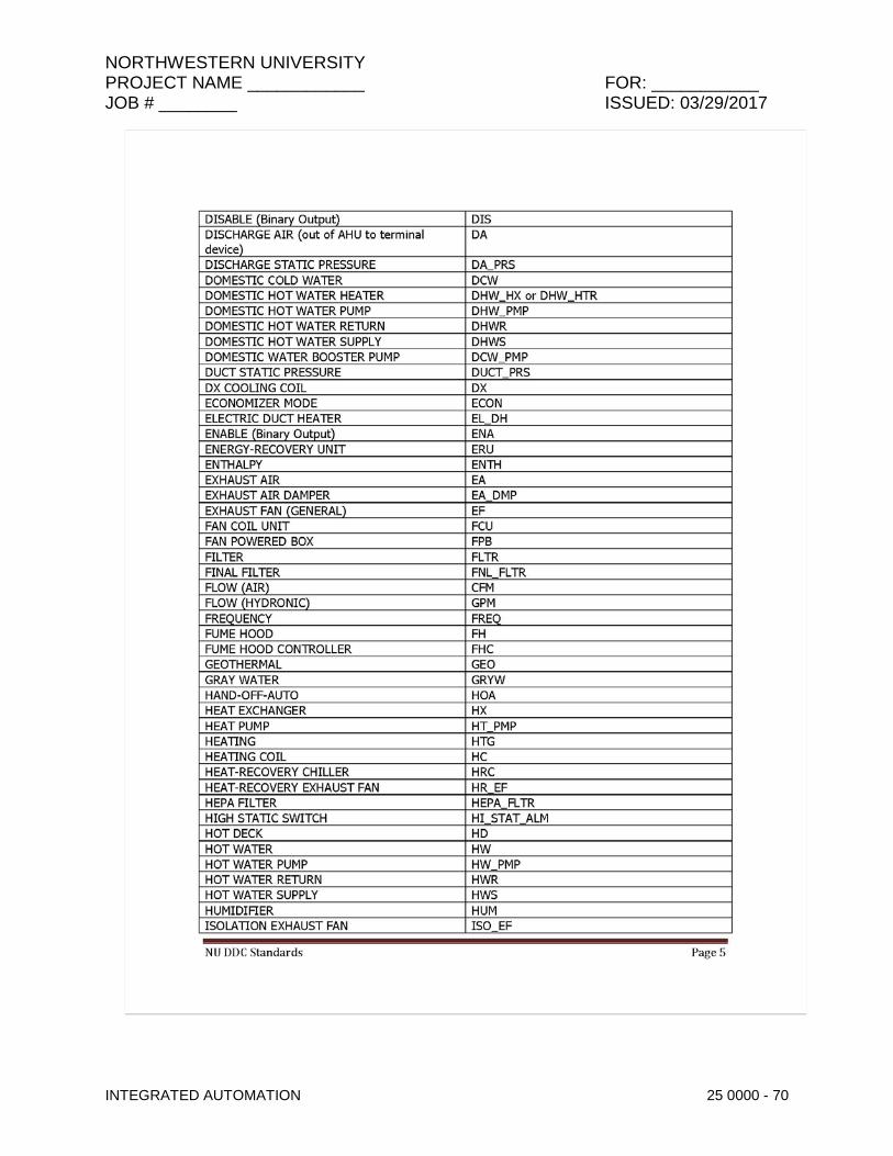
NORTHWESTERN UNIVERSITY PROJECT NAME ____________ FOR: ___________ JOB # ________ ISSUED: 03/29/2017
INTEGRATED AUTOMATION 25 0000 - 70

NORTHWESTERN UNIVERSITY PROJECT NAME ____________ FOR: ___________ JOB # ________ ISSUED: 03/29/2017
INTEGRATED AUTOMATION 25 0000 - 71

NORTHWESTERN UNIVERSITY PROJECT NAME ____________ FOR: ___________ JOB # ________ ISSUED: 03/29/2017
INTEGRATED AUTOMATION 25 0000 - 72

NORTHWESTERN UNIVERSITY PROJECT NAME ____________ FOR: ___________ JOB # ________ ISSUED: 03/29/2017
INTEGRATED AUTOMATION 25 0000 - 73

NORTHWESTERN UNIVERSITY PROJECT NAME ____________ FOR: ___________ JOB # ________ ISSUED: 03/29/2017
INTEGRATED AUTOMATION 25 0000 - 74

NORTHWESTERN UNIVERSITY PROJECT NAME ____________ FOR: ___________ JOB # ________ ISSUED: 03/29/2017
INTEGRATED AUTOMATION 25 0000 - 75
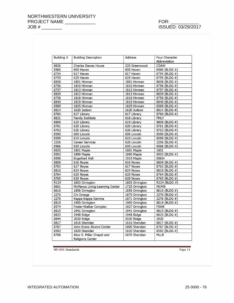
NORTHWESTERN UNIVERSITY PROJECT NAME ____________ FOR: ___________ JOB # ________ ISSUED: 03/29/2017
INTEGRATED AUTOMATION 25 0000 - 76

NORTHWESTERN UNIVERSITY PROJECT NAME ____________ FOR: ___________ JOB # ________ ISSUED: 03/29/2017
INTEGRATED AUTOMATION 25 0000 - 77
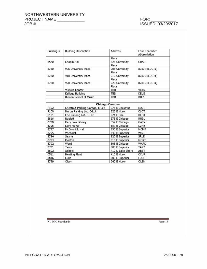
NORTHWESTERN UNIVERSITY PROJECT NAME ____________ FOR: ___________ JOB # ________ ISSUED: 03/29/2017
INTEGRATED AUTOMATION 25 0000 - 78

NORTHWESTERN UNIVERSITY PROJECT NAME ____________ FOR: ___________ JOB # ________ ISSUED: 03/29/2017
INTEGRATED AUTOMATION 25 0000 - 79

NORTHWESTERN UNIVERSITY PROJECT NAME ____________ FOR: ___________ JOB # ________ ISSUED: 03/29/2017
INTEGRATED AUTOMATION 25 0000 - 80

NORTHWESTERN UNIVERSITY PROJECT NAME ____________ FOR: ___________ JOB # ________ ISSUED: 03/29/2017
INTEGRATED AUTOMATION 25 0000 - 81

NORTHWESTERN UNIVERSITY PROJECT NAME ____________ FOR: ___________ JOB # ________ ISSUED: 03/29/2017
INTEGRATED AUTOMATION 25 0000 - 82
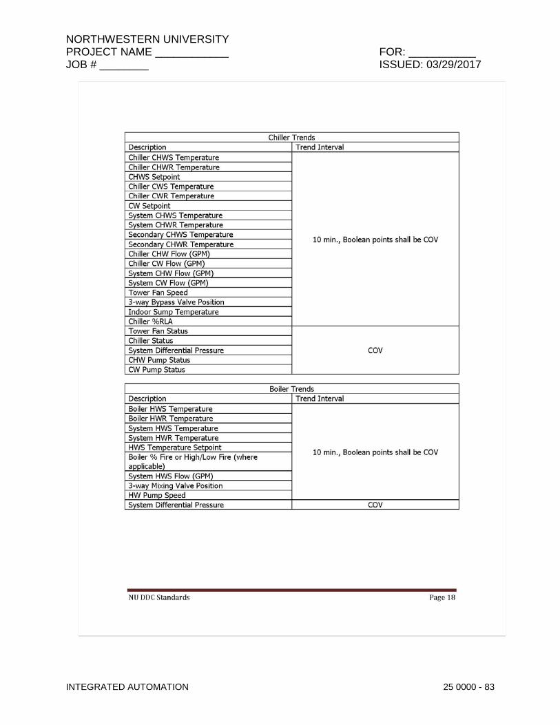
NORTHWESTERN UNIVERSITY PROJECT NAME ____________ FOR: ___________ JOB # ________ ISSUED: 03/29/2017
INTEGRATED AUTOMATION 25 0000 - 83

NORTHWESTERN UNIVERSITY PROJECT NAME ____________ FOR: ___________ JOB # ________ ISSUED: 03/29/2017
INTEGRATED AUTOMATION 25 0000 - 84

NORTHWESTERN UNIVERSITY PROJECT NAME ____________ FOR: ___________ JOB # ________ ISSUED: 03/29/2017
INTEGRATED AUTOMATION 25 0000 - 85

NORTHWESTERN UNIVERSITY PROJECT NAME ____________ FOR: ___________ JOB # ________ ISSUED: 03/29/2017
INTEGRATED AUTOMATION 25 0000 - 86

NORTHWESTERN UNIVERSITY PROJECT NAME ____________ FOR: ___________ JOB # ________ ISSUED: 03/29/2017
INTEGRATED AUTOMATION 25 0000 - 87

NORTHWESTERN UNIVERSITY PROJECT NAME ____________ FOR: ___________ JOB # ________ ISSUED: 03/29/2017
INTEGRATED AUTOMATION 25 0000 - 88

NORTHWESTERN UNIVERSITY PROJECT NAME ____________ FOR: ___________ JOB # ________ ISSUED: 03/29/2017
INTEGRATED AUTOMATION 25 0000 - 89

NORTHWESTERN UNIVERSITY PROJECT NAME ____________ FOR: ___________ JOB # ________ ISSUED: 03/29/2017
INTEGRATED AUTOMATION 25 0000 - 90

NORTHWESTERN UNIVERSITY PROJECT NAME ____________ FOR: ___________ JOB # ________ ISSUED: 03/29/2017
INTEGRATED AUTOMATION 25 0000 - 91

NORTHWESTERN UNIVERSITY PROJECT NAME ____________ FOR: ___________ JOB # ________ ISSUED: 03/29/2017
INTEGRATED AUTOMATION 25 0000 - 92

NORTHWESTERN UNIVERSITY PROJECT NAME ____________ FOR: ___________ JOB # ________ ISSUED: 03/29/2017
INTEGRATED AUTOMATION 25 0000 - 93

NORTHWESTERN UNIVERSITY PROJECT NAME ____________ FOR: ___________ JOB # ________ ISSUED: 03/29/2017
INTEGRATED AUTOMATION 25 0000 - 94
NORTHWESTERN UNIVERSITY PROJECT NAME ____________ FOR: ___________ JOB # ________ ISSUED: 03/29/2017
INTEGRATED AUTOMATION 25 0000 - 95

NORTHWESTERN UNIVERSITY PROJECT NAME ____________ FOR: ___________ JOB # ________ ISSUED: 03/29/2017
INTEGRATED AUTOMATION 25 0000 - 96

NORTHWESTERN UNIVERSITY PROJECT NAME ____________ FOR: ___________ JOB # ________ ISSUED: 03/29/2017
INTEGRATED AUTOMATION 25 0000 - 97
PART 5 - ADDITIONAL DIVISION 25 REQUIREMENTS
5.1 GENERAL: Reference NU SCADA Standards including control diagrams, sequences and equipment.
5.2 SCADA GENERAL
A. SUMMARY
This Section includes the following for the advanced metering, monitoring and control of the electrical energy systems of the University, referred to generically as Energy Monitoring and Control System(s) or ECMS. These systems include the electrical power, natural gas distribution (Gen Fuel), fuel gas and fuel oil, The energy systems in each facility are part of a University-Wide utility energy system, rendering the accurate and automated metering, monitoring and control of its facilities’ energy. ECMS systems are comprised of: Virtual servers, PC-based workstation, SoftwareCommunication network, LAN/WANCommunication, interface modules, gateways and media converters, electric meters, power and control, lighting control, volumetric flowmeters, temperature sensors, pressure transducers, and Programmable Logic Controllers (PLC) Relays/Controllers.
5.3 RELATED SECTIONS
The contractor is to ensure that all related work is coordinated among all specification sections, as well as between other Divisions, and that the tender price includes all related work. The referenced sections listed here are for guidance only and are not necessarily a complete list of related sections:Section 26 0511, REQUIREMENTS FOR ELECTRICAL INSTALLATIONS: General electrical requirements and items that are common to more than one section of Division 26. Section 26 0521, LOW-VOLTAGE ELECTRICAL POWER CONDUCTORS AND CABLES (600 VOLTS AND BELOW): Low voltage cable. Section 26 0526, GROUNDING AND BONDING FOR ELECTRICAL SYSTEMS: Requirements for personnel safety and to provide a low impedance path for possible ground fault currents. Section 26 0533, RACEWAY AND BOXES FOR ELECTRICAL SYSTEMS: Conduits. Section 26 1116, SECONDARY UNIT SUBSTATIONS: Unit secondary substation. Section 26 1300, MEDIUM-VOLTAGE SWITCHGEAR: High voltage switchgear. Section 26 1841, MEDIUM-VOLTAGE SWITCHES: High voltage switches. Section 26 2300, LOW-VOLTAGE SWITCHGEAR: Secondary distribution switchgear. Section 26 2411, DISTRIBUTION SWITCHBOARDS: Secondary distribution switchboards. Section 26 2419, MOTOR-CONTROL CENTERS: Motor control assemblies.

NORTHWESTERN UNIVERSITY PROJECT NAME ____________ FOR: ___________ JOB # ________ ISSUED: 03/29/2017
INTEGRATED AUTOMATION 25 0000 - 98
Generators
ATS /MTS
Invertors
Lighting controls
Fire Alarms Mass notification
5.4 OPERATION AND MAINTENANCE OF INTEGRATED AUTOMATION
A. General:
1. The maintenance program for SCADA systems shall consists of the following components.
a. A documented preventative maintenance program b. Concurrent maintenance capabilities, to allow the testing, troubleshooting, repair, and/or replacement of a component or subsystems while redundant components or subsystems are serving the load c. Retention of operational data – the deleted material goes well beyond requirements to ensure proper maintenance and operation.
2. SCADA systems shall be tested periodically under actual or simulated contingency and operations. Periodic systems testing procedures can duplicate or be derived from recommended functional performance testing procedures of individual components, as provided by the manufactures.
B. Maintenance and Testing
1. All maintenance and testing shall meet or exceed the recommended practices for electrical Equipment maintenance, See NFPA 70B- Current edition.
5.5 OPERATOR TRAINING
A. Every project shall include the costs of training for a human–machine interface or HMI which shall present the processed data to a human operator, and through this, the human operator shall learn how to monitor and interacts with the process.
5.6 COMMON WORK RESULTS FOR INTEGRATED AUTOMATION
A. The SCADA system for COPS loads shall be separated from the building management SCADA system –
B. The SCADA system shall be able to assess the damage and determine systems integrity after the “event” -
C. The SCADA systems shall have the capability to provide storage of critical system parameters as a 15-minute rate or more often when out of limited conditions exists
NORTHWESTERN UNIVERSITY PROJECT NAME ____________ FOR: ___________ JOB # ________ ISSUED: 03/29/2017
INTEGRATED AUTOMATION 25 0000 - 99
5.7 SCHEDULES FOR INTEGRATED DESIGN CRITERIA
A. Integrated automation devices and systems typically require Ethernet data circuits. Each Ethernet circuit that will be required for integrated automation devices and systems must be specified in a schedule.
B. Integrated automation systems include (but are not limited to):
1. Electric power and control 2. HVAC/DDC/BAS/BMS/ATC 3. Lighting control 4. Steam meters 5. Water meters 6. Air quality 7. Access control 8. Environmental monitoring 9. Lab systems monitoring
C. Network connectivity: typically automation equipment will be connected to Northwestern University’s private network. Some devices require a connection to the public Internet instead of, or in addition to a private network connection.
D. Preliminary Schedule
1. A preliminary schedule of all expected integrated automation data circuits must be provided at DD to allow Northwestern University IT to plan for future data needs. This schedule will be subject to revision as specific automation systems are selected and designed.
2. The preliminary schedule must indicate for each circuit: a. Building
b. Floor
c. Room
d. System type or purpose
e. Type of network connection: NU private or public internet
f. Required date of circuit activation (estimated)
E. Detailed Schedule/Circuit Request
1. General: Required data circuits must be specifically requested in detail after integrated automation systems are selected and designed.
2. Circuit request form: The FMIT Building Systems Data Circuit Request form must be used to request data circuits. Contractors should fill out the “Building/Campus” information and the due date, and then all information beginning with the “Vendor:” section. This form can be found at the end of this PART 5 section.
3. Information required: a. Due date
b. Vendor name, contact name, email, phone

NORTHWESTERN UNIVERSITY PROJECT NAME ____________ FOR: ___________ JOB # ________ ISSUED: 03/29/2017
INTEGRATED AUTOMATION 25 0000 - 100
c. Contractor name, contact name, email, phone
d. Building
e. Floor
f. Room
g. Purpose/system
h. Status of wiring and jack installation
i. Jack # (if installed)
j. NU circuit number (EDC or CDC) if the jack is labeled with one
k. Comments
4. NU’s FMIT group will fill in: a. IP address to be assigned to the equipment on the circuit
b. Subnet for the circuit
5. Submittal: Circuit request forms should be submitted to the Northwestern University project manager for verification and approval. The project manager will fill in the top part of the form as the requestor, and will provide work order and chartstring information. If the request is approved, the project manager will forward it to FMIT, and FMIT will work with NUIT to have the circuit activated.
6. Deadlines: timely circuit requests allow the automation systems to be brought online on schedule and the overall project to be completed efficiently. Circuit requests should be submitted as soon as possible, but no later than the following deadlines:
a. Wiring is in place and jack is installed: the NU project manager must receive the cir-
cuit request at least 10 business days before the requested activation date.
b. No wiring is in place: the NU project manager must receive the circuit request at least 30 business days before the requested activation.
7. Note on cables and jacks: existing data circuits and new circuits must conform to NUIT’s current standards for data cable and termination. Circuits must have passed NUIT’s required tests before they can be activated.
5.8 COMMISSIONING OF INTEGRATED AUTOMATION
A. Follow all NFPA 3 and 4 for commissioning requirements. All commissioning shall be integrated testing with all other related equipment.
5.9 INTEGRATED AUTOMATION NETWORK EQUIPMENT
A. GENERAL
1. SUMMARY AND RELATED SECTIONS
NORTHWESTERN UNIVERSITY PROJECT NAME ____________ FOR: ___________ JOB # ________ ISSUED: 03/29/2017
INTEGRATED AUTOMATION 25 0000 - 101
a. Section Includes: System requirements for Local Area Network (LAN) for Building Energy Monitoring and Control System (EMCS).
b. Related Sections: Section 25 0501 – EMCS: General Requirements.
2. REFERENCES
a. Institute of Electrical and Electronics Engineers (IEEE)/Standard for Information Technology – Telecommunications and information exchange between systems – Local and metropolitan area networks – Specific requirements. IEEE Std 802.3TM, Part 3: Carrier sense multiple access with collision detection (CSMA/CD) access method and physical layer specifications.
b. Telecommunications Industries Association (TIA)/Electronic Industries Alliance (EIA). TIA/EIA-568, Commercial Building Telecommunications Cabling Standards Set, Part 1 General Requirements, Part 2 Balanced Twisted- Pair Cabling Components, Part 3 Optical Fiber Cabling Components Standard. TIA/EIA-569-A, Commercial Building Standard for Telecommunications Pathways and Spaces.
3. DEFINITIONS
a. Acronyms and definitions: refer to Section 25 0501 – EMCS: General Requirements.
4. SYSTEM DESCRIPTION
a. Data communication network to link Operator Workstations and Master Control Units (MCU) in accordance with TIA/EIA-568 and TIA/EIA-569-A. Provide reliable and secure connectivity of adequate performance between different sections segments of network. Allow for future expansion of network, with selection of networking technology and communication protocols.
b. Data communication network to included, but not limited to: EMCS-LAN. Modems. Network interface cards. Network management hardware and software. Network components necessary for complete network. Network gateways Network media converters
5. DESIGN REQUIREMENTS
a. EMCS Local Area Network (EMCS-LAN). High Speed, high performance, local area network over MS/TP with MCUs and OWSs communicate with each other directly on peer to peer basis in accordance with IEEE 802.3/Ethernet Standard. EMCS-LAN may be any combination of devices using the protocols: ModbusTCP, DNP-TCP, AB Micrologix, or BACnet Protocol BACNet protocol shall only be applied in conditions where data on the network is fully contained and utilized within one network subnet. Each EMCS-LAN subnet to be capable of supporting at least 200 devices.

NORTHWESTERN UNIVERSITY PROJECT NAME ____________ FOR: ___________ JOB # ________ ISSUED: 03/29/2017
INTEGRATED AUTOMATION 25 0000 - 102
Support of combination of MCUs and OWSs directly connected to EMCS-LAN. High speed data transfer rates for alarm reporting, quick report generation from multiple controllers, upload/download information between network devices. Bit rate to be 10 Megabits per second minimum. Detection and accommodation of single or multiple failures of either OWSs, MCUs or network media. Operational equipment to continue to perform designated functions effectively in event of single or multiple failures. Commonly available, multiple sourced, networking components and protocols to allow system to co-exist with other networking applications including office automation.
b. Dynamic Data Access. LAN to provide capabilities for OWSs, either network resident or connected remotely to access point status and application report data or execute control functions for other devices via LAN. Access to data to be based upon logical identification of building equipment.
c. Network Medium. Network medium: twisted cable, shielded twisted cable, or fiber optic cable compatible with network protocol to be used. Cabling to be CAT-5E or CAT-6 Fiber optic cable to be used between buildings and between buildings and medium voltage switchgear.
5.10 INTEGRATED AUTOMATION NETWORK DEVICES
A. Should we drop in the numbering systems Jim Hall was talking about?
5.11 INTEGRATED AUTOMATION NETWORK GATEWAYS
A. GENERAL/SUMMARY
1. In the context of the ECMS, gateways are generally deployed to provide conversion of protocol, media or both.
2. Protocol conversion is generally limited to conversion between different physical forms of the same protocol, for example, from Modbus RTU to Modbus TCP. However protocol conversion may require conversion from one protocol to a completely different protocol, such as from BACnet to Modbus TCP.
3. Media conversion is generally understood to be conversion from two-wire or four-wire serial forms to Ethernet IP. Serial media will typically be connected through either RS-232, RS-422, or RS-485 formats.
4. All physical devices supplying data to the ECMS network must connect to the network using Ethernet. If a particular device does not support Ethernet connectivity directly, then a suitable gateway must be installed to connect the device to the North western Ethernet LAN.
5.12 INTEGRATED AUTOMATION SOFTWARE
A. GENERAL/SUMMARY
1. Integrated automation software shall consist of a suite of inter-operable software products that provide for data collection, data manipulation, historizing, and analysis, including dashboards.

NORTHWESTERN UNIVERSITY PROJECT NAME ____________ FOR: ___________ JOB # ________ ISSUED: 03/29/2017
INTEGRATED AUTOMATION 25 0000 - 103
B. PRODUCTS
1. ACCEPTABLE SYSTEMS, MANUFACTURERS
a. Schneider Electric products including Citect SCADA Vijeo Citect Wonderware Historian Ampla MES Ampla Dashboard
b. Software integration design and implementation by Centric Energy Systems; Contact Dennis Stewart, [email protected]
c. Proposed system as installed shall include capability of utilizing Modbus TCP, DNP-TCP, AB Micrologix, and BACnet protocols.
5.13 INTEGRATED AUTOMATION INSTRUMENTATION & TERMINAL DEVICES FOR ELECTRICAL SYSTEMS
A. GENERAL/SUMMARY
1. This section identifies hardware and data requirements for devices that are connected to the electric system.
B. Electric Metering
1. The following data must be provided by electrical power metering devices Three-phase voltage, phase-to-neutral for all wyee connected circuits Three-phase voltage, phase-to-phase for all circuits Three-phase amps for each phase Neutral amps Three-phase power load kW Three-phase reactive power load kVAR Three-phase apparent power load kVA Delivered energy kWh as an integer value Frequency Three-phase demand amps for each phase Meter date/time
2. Electric power meters must provide the following remote controls for meter data through the digital connection using the meter protocol Energy register reset Change meter date/time
3. Electric power meters shall communicate and provide data in one of the following protocols Modbus RTU Modbus TCP DNP DNP TCP
4. Electric power meters shall provide one or more of the following connection types RS-422/RS-485 Ethernet
C. Automatic Transfer Switches
NORTHWESTERN UNIVERSITY PROJECT NAME ____________ FOR: ___________ JOB # ________ ISSUED: 03/29/2017
INTEGRATED AUTOMATION 25 0000 - 104
1. The following data must be provided by electrical automatic transfer switches Three-phase voltage on the Normal and Emergency sides of the switch Transfer Switch position By-pass switch position Normal source available Emergency source available
2. Automatic transfer switches shall communicate and provide data in one of the following protocols Modbus RTU Modbus TCP DNP DNP TCP
3. Automatic transfer switches shall provide one or more of the following connection types RS-422/RS-485 Ethernet
D. Monitored Circuit Breakers (Low Voltage)
1. The following data must be provided by electrical circuit breakers Three-phase amps for each phase Switch position (open/closed/tripped) Fault targets (reason for Trip) Control failure or alarm flag Breaker operation count
2. Circuit breakers shall communicate and provide data in one of the following protocols Modbus RTU Modbus TCP DNP DNP TCP
3. Circuit breakers shall provide one or more of the following connection types RS-422/RS-485 Ethernet
4. Monitored circuit breakers must provide remote control through the data connection Breaker open command Breaker close command
E. Monitored Circuit Breakers (Medium Voltage)
1. The following data must be provided by electrical circuit breakers Three-phase voltage, phase-to-neutral for all wyee connected circuits Three-phase voltage, phase-to-phase for all circuits Three-phase amps for each phase Neutral amps Three-phase power load kW Three-phase reactive power load kVAR Three-phase apparent power load kVA Delivered energy kWh as an integer value Frequency Three-phase demand amps for each phase Switch position (open/closed/tripped) Fault targets (reason for Trip) Control failure or alarm flag Breaker operation count
2. Circuit breakers shall communicate and provide data in one of the following protocols

NORTHWESTERN UNIVERSITY PROJECT NAME ____________ FOR: ___________ JOB # ________ ISSUED: 03/29/2017
INTEGRATED AUTOMATION 25 0000 - 105
Modbus RTU Modbus TCP DNP DNP TCP
3. Circuit breakers shall provide one or more of the following connection types RS-422/RS-485 Ethernet
4. Monitored circuit breakers must provide remote control through the data connection Breaker open command Breaker close command Fault target reset Energy register reset Change meter date/time
F. Generators
G. Inverters
H. Fire Alarms
5.14 On the next page is the Building Systems Data Circuit Request Form, as referenced in paragraph 5.7.

NORTHWESTERN UNIVERSITY PROJECT NAME ____________ FOR: ___________ JOB # ________ ISSUED: 03/29/2017
INTEGRATED AUTOMATION 25 0000 - 106

NORTHWESTERN UNIVERSITY PROJECT NAME ____________ FOR: ___________ JOB # ________ ISSUED: 03/29/2017
INTEGRATED AUTOMATION 25 0000 - 107
PART 6 - DDC CONTROL SYSTEM SEQUENCES OF OPERATION
6.1 TBD by project AE.
END OF SECTION 25 0000

NORTHWESTERN UNIVERSITY PROJECT NAME ____________ FOR: ___________ JOB # ________ ISSUED: 03/29/2017
INTEGRATED AUTOMATION 25 0000 - 108
THIS PAGE IS INTENTIONALLY BLANK

NORTHWESTERN UNIVERSITY PROJECT NAME ____________ FOR: ___________ JOB # ________ ISSUED: 03/29/2017
COMMISSIONING OF INTEGRATED AUTOMATION 25 0800 - 1
SECTION 25 0800 - COMMISSIONING OF INTEGRATED AUTOMATION
GENERAL
1.1 SUMMARY
This section defines responsibilities of the Integrated Automation Contractor to facilitate the Commissioning process for the Building Automation System (BAS).
Commissioning is the process of ensuring that building systems are installed and perform interactively according to the design intent, the systems are efficient and cost effective and meet the Owner’s operational needs, and the installation is adequately documented and that the Operators are adequately trained. It serves as a tool to minimize post-occupancy operational problems. It establishes testing and communication protocols in an effort to advance the building systems from installation to full dynamic operation and optimization.
Commissioning Authority shall work with the GC and the A/E to direct and oversee the Cx process and perform functional performance testing.
The Commissioning Plan outlines the Commissioning Process. The Commissioning Plan is part of the Contract Documents and stipulates Contractor responsibilities that are part of this project. It also provides examples of functional performance testing that the contractor must participate in. The commissioning plan shall be referenced for details of the Cx process.
This section, along with Section 01 9113, defines responsibilities of the Contractor to facilitate the Commissioning process particularly during the Construction Phase.
This section includes:
1. BAS (Building Automation System) and equipment testing and start-up. 2. Validation of proper and thorough installation of BAS systems and equipment. 3. Functional testing of control systems. 4. Documentation of tests, procedures, and installations. 5. Coordination of BAS training. 6. Documentation of BAS Operation and Maintenance materials.
Refer to Division 01, Section 01 9113, for a full list of commissioning related definitions. A few critical definitions are included below:
1. Commissioning. A systematic process that provides documented confirmation that specific and interconnected building automation systems function according to the intended design criteria set forth in the project documents and satisfy the owner’s operational needs, including compliance requirements of any applicable laws, regulations, codes, and standards requiring building automation systems.
2. Commissioning Authority (CxA). The qualified person, company, or agency that plans, coordinates, and oversees the entire Cx process.
3. Commissioning Plan. The document prepared for each project, which identifies the processes and procedures necessary for a successful Cx process.

NORTHWESTERN UNIVERSITY PROJECT NAME ____________ FOR: ___________ JOB # ________ ISSUED: 03/29/2017
COMMISSIONING OF INTEGRATED AUTOMATION 25 0800 - 2
4. Commissioning Record. The complete set of commissioning documentation for the project, which is turned over to Northwestern facilities at the end of the construction phase.
5. Functional Testing. Tests performed to verify compliance with manufacturers’ specifications, applicable codes and standards, and the project Basis of Design (BOD) and Owner’s Project Requirement (OPR).
1.2 RELATED SECTIONS
Division 01 Section 01 9113 - General Commissioning Requirements
Division 21 Section 21 0800 - Commissioning of Fire Suppression
Division 22 Section 22 0800 - Commissioning of Plumbing Systems
Division 23 Section 23 0800 - Commissioning of HVAC Systems
Division 26 Section 26 0800 - Commissioning of Electrical Systems
Individual Division 01, 21, 22, 23, 25, and 26 sections contain requirements related to the commissioning process.
1.3 ROLES AND RESPONSIBILITIES
Refer to Section 01 9113 for Commissioning Authority, Owner, Architect, and General Contractor roles and responsibilities.
Refer to Section 21 0800 for fire protection contractor roles and responsibilities.
Refer to Section 22 0800 for plumbing contractor roles and responsibilities.
Refer to Section 23 0800 for mechanical contractor roles and responsibilities.
Refer to Section 26 0800 for electrical contractor roles and responsibilities.
Integrated Automation Contractors
1. Include cost for commissioning requirements in the contract price, including assisting the Commissioning Authority with implementation of Functional Test Procedures and reviewing control system operation with the Commissioning Authority.
2. Review design for controllability with respect to selected manufacturers equipment:
a. Verify proper hardware specification exists for functional performance required by specification and sequence of operation.
b. Verify proper safeties and interlocks are included in design. c. Verify proper sizing of control valves and actuators based on design pressure drops.
Verify control valve authority to control coil properly. d. Verify proper sizing of control dampers. Verify damper authority to control air
stream. Verify proper damper positioning for mixing to prevent stratification. Verify actuator and damper sections for smooth operation.
e. Verify proper selection of sensor ranges. f. Clarify all questions of operation.

NORTHWESTERN UNIVERSITY PROJECT NAME ____________ FOR: ___________ JOB # ________ ISSUED: 03/29/2017
COMMISSIONING OF INTEGRATED AUTOMATION 25 0800 - 3
3. Attend initial commissioning coordination meeting scheduled by the Commissioning Authority.
4. Provide the following submittals to the GC:
a. Hardware and software submittals. b. Control panel construction shop drawings. c. Narrative description of each control sequence for each piece of equipment
controlled. d. Diagrams showing all control points, sensor locations, point names, actuators,
controllers and, where necessary, points of access, superimposed on diagrams of the physical equipment.
e. Logic diagrams showing the logic flow of the system. f. A list of all control points, including analog inputs, analog outputs, digital inputs, and
digital outputs. Include the values of all parameters for each system point. Provide a separate list for each stand-alone control unit.
g. A complete control language program listing including all software routines employed in operating the control system. Also provide a program write-up, organized in the same manner as the control software. This narrative shall describe the logic flow of the software and the functions of each routine and sub-routine. It should also explain individual math or logic operations that are not clear from reading the software listing.
h. Hardware operation and maintenance manuals. i. Application software and project applications code manuals.
5. Verify proper installation and performance of controls/BAS hardware and software provided by others.
6. Integrate installation and programming schedule with construction and commissioning schedules.
7. Provide thorough training to operating personnel on hardware operations and programming, and the application program for the system.
8. Demonstrate system performance to Commissioning Authority including all modes of system operation (e.g. normal, abnormal, and emergency).
9. Provide control system technician for use during Pre-functional Checklists and Functional Performance Testing.
10. Provide system modifications as required. 11. Provide support and coordination with TAB contractor on all interfaces between their
scopes of work. Provide all devices, such as portable operator terminals, for TAB use in completing TAB procedures.
12. Provide trend logs as required to facilitate the Commissioning Process.
1.4 SEQUENCING
The following list outlines the general sequence of events for submittals and commissioning of the BAS.
1. Submit Product data and Shop Drawings, and receive A/E and Owner acceptance. 2. Submit Control Logic Documentation, and receive A/E and Owner acceptance. 3. Submit startup checklists and manufacturers startup procedures for all equipment provided
by the BAS contractor. 4. Install BAS controls. 5. Submit BAS startup test Agenda/schedule to CxA and GC for review and acceptance. 6. Submit Training Plan. 7. Place systems under BAS control. 8. Prepare and initiate Trend Log data storage and format trend graphs.

NORTHWESTERN UNIVERSITY PROJECT NAME ____________ FOR: ___________ JOB # ________ ISSUED: 03/29/2017
COMMISSIONING OF INTEGRATED AUTOMATION 25 0800 - 4
9. Perform BAS system startup. 10. Submit completed BAS startup reports. 11. Receive BAS startup report acceptance and approval to schedule Commissioning
Demonstrations. 12. Demonstrate system performance as requested by Owner and CxA. 13. Submit trend logs in format specified. 14. Receive Demonstration acceptance and approval to schedule Acceptance Period. 15. Train Owner on control system operation and maintenance. 16. Substantial Completion. 17. Begin Acceptance Phase. 18. Two-week Operational Test. 19. Perform Functional Performance Testing. 20. Receive Acceptance Period approval which is Functional Completion for the BAS. 21. Train Owner on final Sequences and modes of operation. 22. Install Framed Control Drawings. 23. Provide password access to Owner. 24. Revise and Re-Submit Record drawings and O&M manuals. 25. Begin Warranty Phase. 26. Schedule and begin Opposite Season Acceptance Period. 27. Receive Opposite Season Acceptance Period approval. 28. Submit As-Built drawings and O&M manuals. 29. Update Framed Control Drawings. 30. Complete Owner training. 31. Final Acceptance.
1.5 SCOPE OF WORK
Refer to Section 21 0800 for listing of fire suppression systems to be commissioned and requirements.
Refer to Section 22 0800 for listing of plumbing systems to be commissioned and requirements.
Refer to Section 23 0800 for listing of HVAC systems to be commissioned and requirements.
Refer to Section 26 0800 for listing of Electrical Systems to be commissioned and requirements.
Integrated Automation scope of work includes the controls and automation related to systems described in the above reverenced Divisions.
PRODUCTS
2.1 TEST EQUIPMENT
All industry standard test equipment required for performing the specified tests shall be provided by the applicable contractor (as specified) and shall be approved by the CxA. Any proprietary vendor specific test equipment shall be provided by the equipment vendor or manufacturer.
Any portable or hand-held setup / calibration devices required to initialize the control system shall be made available by the control vendor (at no cost) to the contract or CxA.

NORTHWESTERN UNIVERSITY PROJECT NAME ____________ FOR: ___________ JOB # ________ ISSUED: 03/29/2017
COMMISSIONING OF INTEGRATED AUTOMATION 25 0800 - 5
The instrumentation used in the commissioning process shall meet the following standards:
1. Be of sufficient quality and accuracy to test and/or measure system performance within the tolerances required.
2. Be calibrated at the manufacturer’s recommended intervals with calibration tags permanently affixed to the instrument
3. Be maintained in good repair and operating condition throughout the duration of use on this project.
4. Be immediately re-calibrated or repaired if dropped and/or damaged in any way during use on this project.
2.2 BAS HARDWARE AND SOFTWARE
Field Panel Software and Hardware
1. The BAS Contractor shall furnish the CxA with two (2) copies of all hardware and software needed to connect to, communicate with and command the BAS field panels and controllers at no additional charge to the CxA. This hardware and software will be used by the CxA for execution of the commissioning process. Software and hardware provided to the CxA for this purpose, does not include any provisions for use by the Test & Balance Contractor.
2. Hardware and software covered under this requirement includes, but is not limited to:
a. Latest versions of proprietary software such as Johnson Controls HVAC Pro, Siemens Building Technologies CIS, etc.
b. Communication modules, software keys, and similar hardware needed for communication from a laptop computer, PDA or similar device to field panels or controllers
c. Proprietary cables required for communication between laptop computers or PDAs to field panels or controllers
d. Passwords, access levels and similar software permissions necessary for execution of the Cx Process.
e. Software and hardware manuals for all control system hardware and software provided to the CxA.
3. This requirement is not meant to include provision of standard hardware such as laptop computers and PDAs nor provision of standard software such as Windows or MS Explorer.
4. At the conclusion of the Commissioning Process, this hardware and software will be turned over back to the contractor.
Front-End Software & Hardware
1. The BAS Contractor shall furnish the CxA with one (1) copy of their front-end software and associated hardware as needed to connect to, communicate with, and command the BAS at no additional charge to the CxA.
2. Hardware and software covered under this requirement includes, but is not limited to:
a. Proprietary software needed to communicate to field panels or controllers such as Johnson Controls Metasys, Siemens Building Technologies Apogee, ALC, Tridium etc. Revision levels for all software shall be identical with the revision level being provided to the project for the front-end operator workstation(s).
b. Communication modules, software keys, and similar hardware needed for operation of the software or to communicate with the BAS.

NORTHWESTERN UNIVERSITY PROJECT NAME ____________ FOR: ___________ JOB # ________ ISSUED: 03/29/2017
COMMISSIONING OF INTEGRATED AUTOMATION 25 0800 - 6
c. Proprietary cables required for communication between laptop computers and the BAS.
d. Passwords, access levels and similar software permissions necessary for execution of the Cx Process.
e. Software and hardware manuals for all control system hardware and software provided to the CxA.
3. This requirement is not meant to include provision of standard hardware such as laptop computers nor provision of standard software such as Windows or MS Explorer.
Operator Workstation Access
1. The BAS Contractor shall provide the CxA with software and hardware needed for accessing the BAS’ front-end operator workstation(s). At a minimum, this shall include appropriate level user identification names and passwords. Access level shall allow the CxA to fully execute all commissioning procedures and will include the ability to:
a. View system operation b. Override setpoints c. Command digital and analog output points d. View BAS programming source code (read-only) e. View and print graphics f. Create, view, modify, print and download trend logs, histories and reports
Technical Support
1. The BAS Contractor shall also provide technical support to the CxA as reasonably requested by the CxA regarding setting up and operating BAS hardware and software to support successful execution of the Cx Process.
Duration of Support
1. The BAS Contractor shall provide the CxA with technical support for the duration of the project, through the post occupancy phase commissioning activities, warranty period, and seasonal testing of the project to support the Cx process. The duration of this support is typically one year after turn over to Northwestern facilities, to provide time to complete deferred and seasonal testing and the warranty phase activities.
EXECUTION
3.1 GENERAL
A pre-construction meeting of all Commissioning Team members shall be held at a time and place designated by Northwestern University. The purpose shall be to familiarize all parties with the Commissioning Process, and to ensure that the responsibilities of each party are clearly understood.
The Contractor shall complete all phases of work so the systems can be started, tested, balanced, and commissioning procedures undertaken. This includes the complete installation of all equipment, materials, pipe, duct, wire, insulation, controls, etc., per the contract documents and related directives, clarifications, and change orders.
NORTHWESTERN UNIVERSITY PROJECT NAME ____________ FOR: ___________ JOB # ________ ISSUED: 03/29/2017
COMMISSIONING OF INTEGRATED AUTOMATION 25 0800 - 7
A Commissioning Plan shall be developed by the Commissioning Authority. The Contractor shall assist the Commissioning Authority in preparing the Commissioning Plan by providing all necessary information pertaining to the actual equipment and installation. If contractor-initiated system changes have been made that alter the Commissioning Process, the Commissioning Authority shall notify the Owner.
Acceptance procedures are normally intended to begin prior to completion of a system and/or sub-systems, and shall be coordinated with the Division 25 contractor. Start of acceptance procedures before system completion does not relieve the contractor from completing those systems as per the schedule.
3.2 PARTICIPATION IN COMMISSIONING
The Contractor shall provide skilled technicians to start-up and debug all systems within Divisions 21, 22, 23, 25, and 26. These same technicians shall be made available to assist the Commissioning Authority in completing the commissioning program. Work schedules, time required for testing, etc., shall be requested by the Commissioning Authority and coordinated by the contractor. Contractor shall ensure that the qualified technician(s) are available and present during the agreed upon schedules and of sufficient duration to complete the necessary tests, adjustments, and/or problem resolutions.
System performance problems and discrepancies may require additional technician time, Commissioning Authority time, reconstruction of systems, and/or replacement of system components. The additional technician time shall be made available for subsequent commissioning periods until the required system performance is obtained.
The Commissioning Authority reserves the right to question the appropriateness and qualifications of the technicians relative to each item of equipment, system, and/or sub-system. Qualifications of technicians shall include expert knowledge relative to the specific equipment involved and a willingness to work with the Commissioning Authority. Contractor shall provide adequate documentation and tools to start up and test the equipment, system, and/or sub-system.
3.3 DEFICIENCY RESOLUTION
In some systems, maladjustments, misapplied equipment, and/or deficient performance under varying loads will result in additional work being required to commission the systems. This work shall be completed under the direction of the Owner, with input from the contractor, equipment manufacturer, and Commissioning Authority. Whereas all members shall have input and the opportunity to discuss, debate, and work out problems, the Owner shall make final determination over any additional required work to achieve performance.
Corrective work shall be completed in a timely fashion to permit the completion of the Commissioning Process. Experimentation to demonstrate system performance may be permitted. If the Commissioning Authority deems the experimentation work to be ineffective or untimely as it relates to the Commissioning Process, the Commissioning Authority shall notify the Owner, indicating the nature of the problem, expected steps to be taken, and suggested deadline(s) for completion of activities. If the deadline(s) pass without resolution of the problem, the Owner reserves the right to obtain supplementary services and/or equipment to resolve the problem. Costs incurred to solve the problems in an expeditious manner shall be the contractor’s responsibility.
The Owner’s contract with the Commissioning Authority includes up to two Functional Performance Tests of each piece of equipment or system included in the commissioning scope.

NORTHWESTERN UNIVERSITY PROJECT NAME ____________ FOR: ___________ JOB # ________ ISSUED: 03/29/2017
COMMISSIONING OF INTEGRATED AUTOMATION 25 0800 - 8
Commissioning Authority time and expenses required for retests beyond two, if required, due to incomplete installation or otherwise, will be paid by the Owner and reimbursed by the contractor.
3.4 ADDITIONAL COMMISSIONING
Additional commissioning activities may be required after system adjustments, replacements, etc., are completed. The contractor(s), manufacturers, and Commissioning Authority shall include a 5% contingency allowance to complete this work as part of their contractual obligations.
3.5 SEASONAL COMMISSIONING
Seasonal commissioning pertains to testing under full load conditions during peak heating and peak cooling seasons, as well as part load conditions during off-peak periods. Initial commissioning shall be done as soon as contract work is completed, regardless of season. Subsequent commissioning may be undertaken at any time thereafter to ascertain adequate performance during the different peak and off-peak conditions. Each contractor and manufacturer shall be responsible to participate in the initial and the alternate peak and off-peak tests of the systems as required to demonstrate performance.
3.6 CONSTRUCTION PHASE OBSERVATION
Scope of Construction Phase Observation
1. The Commissioning Authority will conduct periodic observations during the Construction Phase to monitor progress and compliance with the design intent and contract documents. It is the responsibility of the contractor to address the issues noted on the Issues Log and notify Commissioning Authority of completion.
2. Commissioning Authority observations will coincide with Design Team observations and are not intended to take the place of this work.
Documentation and Reporting
1. Issues identified by the Commissioning Authority during Construction Phase will be documented on the Web-based Commissioning Software (WCxS) and distributed to Commissioning Team members.
2. Progress during the Construction Phase will also be documented by the Commissioning Authority using Commissioning Process Reports.
3.7 CONTRACTOR STARTUP TESTING
The contractors shall conduct all startup testing as required by the specifications, equipment manufacturer, the manufacturer's installation, operations and maintenance manual or as necessary to verify all equipment is properly installed.
Startup testing shall be documented. Appropriate documentation shall be by the contractor and/or the manufacturer's representative or entity specified in the construction documents.
The startup testing may be documented using the contractors or manufacturer's standard forms.

NORTHWESTERN UNIVERSITY PROJECT NAME ____________ FOR: ___________ JOB # ________ ISSUED: 03/29/2017
COMMISSIONING OF INTEGRATED AUTOMATION 25 0800 - 9
3.8 CONTROLS & INSTRUMENTATION TESTING
Prior to start of control system Functional Performance Testing, the Building Automation System (BAS) Contractor shall verify and document that all control systems are installed and operating properly including the following:
1. Control Panels & Hardware Installation shall be fully verified and the appropriate Pre-Functional checklists completed prior to proceeding to subsequent installation/checkout steps.
2. Point-to-Point Checkout shall be completed and documented per the requirements of Integrated Automation and Controls section of Division 25 and item 3 below.
3. Control Sequence Checkout. Contractor shall verify that operation of control system programming matches the specified sequences of operation. For these checkouts, the Contractor shall, as much as possible, simulate actual operating conditions for the various operating modes being tested (heating, cooling, etc) by false-loading systems, adjusting setpoints and similar techniques. The CxA will make the control sequence functional performance tests available to the BAS Contractor for use in these checkouts.
4. Tune all Control Loops to obtain the fastest stable response without unreasonable hunting, offset or overshoot. Record tuning parameters and response test results for each control loop and provide trend reports to document results. Trend logs shall show both steady-state operation and response to setpoint changes.
5. Test All Alarms and Safeties. Record all alarm parameters and alarm messages. Document all alarms and safeties have been tested and are functioning properly.
The BAS Contractor shall work with the TAB Contractor(s) to make sure that changes to the BAS made during TAB, such as flow coefficients, flow setpoints and duct areas are permanently archived in the BAS and become the initial or default values for their respective controllers. If BAS adjustments made by the TAB Contractor(s) get lost or overwritten prior to archiving, it shall be the BAS Contractor’s responsibility to re-enter this data at no additional cost to the Owner.
Point-to-Point Checkout Requirements
1. Items described in this section apply to and augment the requirements of the Integrated Automation and Controls section of the Division 25 specifications.
a. These procedures will verify the following for each physical control point:
1) Field device is installed per the manufacturer’s recommendations and the project drawings and specifications
2) Field verify calibration of all analog inputs and outputs 3) Verify labeling of controllers, field devices, and wiring 4) Physical points are correctly addressed and communicating properly between
its controller and the field device.
2. Detailed written procedures for execution of Point-to-Point Checkouts shall be submitted to the CxA and Engineer by the Contractor for review and acceptance prior to the start of testing. Include proposed test forms as part of this submittal.
3. The Contractor shall provide all tools and instrumentation necessary for execution of this testing. All instrumentation must be in calibration and meet the requirements of Part 2 of this specification.
4. The CxA reserves the right to field verify up to 5% of the Contractor’s Point-to-Point Checkout testing. The Contractor shall provide the technicians and instrumentation used for the original testing to assist the CxA with this field verification.
NORTHWESTERN UNIVERSITY PROJECT NAME ____________ FOR: ___________ JOB # ________ ISSUED: 03/29/2017
COMMISSIONING OF INTEGRATED AUTOMATION 25 0800 - 10
3.9 ACCEPTANCE PROCEDURES
The Commissioning Authority shall develop the pre-functional checklists (PFC) and distribute them to the GC.
The contractor shall complete the checklists online using the WCxS.
PFCs consist of a series of field observations and verification checks conducted by the contractors during the installation of commissioned equipment to verify the following:
a. Installed equipment matches the specifications and approved submittals b. Equipment is installed per the specifications, drawings and manufacturer’s
recommendations c. Utility connections to equipment, such as electrical, steam, chilled water, etc. have
been successfully completed d. Equipment is ready for functional performance testing
Contractors should expect to complete one (1) PFC for each piece of equipment covered by the commissioning process such as pumps, fans, air handling units, terminal units, control panels, and lighting control panels.
PFCs for mechanical equipment will include verification of the safety devices intended to stop and/or prevent equipment operation unless minimum safety standards or conditions are met. These may include adequate oil pressure, proof-of-flow, non-freezing conditions, maximum static pressure, maximum head pressure, etc. The CxA shall observe the actual performance of safety shutoffs in a real or closely simulated condition of failure.
Systems may include safety devices and components that control a variety of equipment operating as a system. Interlocks may be hard-wired or operate from software. Operation of these interlocks shall be verified by the CxA during functional performance testing.
Additional checklists will be required to verify installation of distribution systems such as piping, ductwork, electrical wire and conduit, etc. The number of required PFCs will vary from system to system, but will typically be limited to one form per system per floor or zone.
The PFC used for this project will be finalized by the CxA after receipt of equipment Installation, Operation & Maintenance (IOM) Manuals from the Contractors.
PFCs shall be completed by the contractor and maintained on-site per the requirements of this specification, Section 1.5 "Commissioning Documentation".
3.10 FUNCTIONAL PERFORMANCE TEST PROCEDURES
Scope
1. Functional Performance Test (FPT) procedures are executed after commissioned equipment and systems have been installed, started-up and balanced. The goal of these procedures is to conclusively verify that commissioned equipment, sub-systems and major systems operate and perform per the design intent, the project specifications and OPR.
2. FPTs will be used to verify operation and capacity of selected equipment and systems such as boilers, chillers, cooling towers, pumps, exhaust fans, air handling units, etc.
a. System operation under both normal and alternate operating conditions and modes b. Interactions between equipment and sub-systems

NORTHWESTERN UNIVERSITY PROJECT NAME ____________ FOR: ___________ JOB # ________ ISSUED: 03/29/2017
COMMISSIONING OF INTEGRATED AUTOMATION 25 0800 - 11
c. Operation of safeties and interlocks d. Control system operation, response time, stability and tuning e. System response to abnormal and/or emergency conditions such as fire, equipment
failure and power outages f. All control sequence of operation strategies, alarm generation and reporting shall
also be reviewed and proper operation verified by the CxA. g. The central work station graphics, point assignments, alarm messages, and logging
functions shall be verified.
Functional Performance Test Forms
1. The commissioning authority will upload the FPTs to the web-based commissioning software.
2. The FPTs used for this project will be finalized by the CxA after receipt of approved contractor submittals, including equipment Installation – Operations & Maintenance manuals.
Contractor Requirements
1. The Cx team will, in a joint effort, coordinate and schedule FPT activities. 2. Scheduling of FPTs shall be contingent on notification from the affected contractor(s) to
the GC and CxA that equipment and systems are ready for checkout. 3. Other prerequisites for execution of FPTs shall include the following:
a. All Pre-Functional Checklists, Contractor Startup Procedures have been completed and documented.
b. TAB has been completed. c. All Cx issues identified affecting equipment or system performance or operations
have been resolved.
4. Prior to claiming readiness for FPT, the controls contractor shall ensure that the following items are completed and documented:
a. Point-to-point checkouts b. Verify that network communication between all devices and systems is established c. Sequence of Operation checkouts d. Printed and annotated trend logs and alarm histories establishing acceptable
operation including
1) Stable control 2) Recovery from upset/changes (e.g., from setback) 3) Special and/or seasonal modes 4) Emergency and alarm modes including loss/restoration of power
5. Execution of the FPTs will be conducted by the contractors providing and installing the equipment and systems being commissioned and the BAS contractors and witnessed by the CxA.
6. Typical activities during FPT execution will include the following
a. Starting/stopping equipment b. Energizing/de-energizing electrical distribution gear c. Opening/closing valves and dampers d. Manipulating BAS inputs, outputs and setpoints e. Setup, collection and downloading of BAS trend data

NORTHWESTERN UNIVERSITY PROJECT NAME ____________ FOR: ___________ JOB # ________ ISSUED: 03/29/2017
COMMISSIONING OF INTEGRATED AUTOMATION 25 0800 - 12
f. Test all modes of operation (normal, failure, backup, emergency, etc.)
7. The Contractor(s) shall maintain full responsibility for the facility, equipment and systems operated during the FPTs, maintain all guarantees and warranties, and shall repair any damage to the facility caused during the FPTs.
8. Contractors shall conduct seasonal FPTs as necessary. This includes performing FPTs on equipment during the season it is intended to operate (i.e. test cooling equipment during the peak cooling season and test heating equipment during the peak heating season, etc.). All seasonal FPT's shall be witnessed by the CxA.
9. Tools, test equipment and instrumentation required for completion of the FPTs shall be provided by the contractor.
10. Special-purpose or proprietary tools, test equipment and instrumentation shall be provided by the contractors.
11. All instruments shall meet the requirements of Part 2 of this specification. 12. FPT acceptance shall confirm the performance of systems to the extent of the design
intent. When a system is accepted, the Owner shall be assured that the system is complete, works as intended, is correctly documented, and operator training has been performed.
3.11 COST OF RE-EVALUATION
The cost for Contractors to re-evaluate any Commissioning Procedure due to open issues shall be borne by the contractors.
The CxA will be available for two attempts of the Functional Performance Tests (one initial and one re-try) with minimal follow-up where necessary (due to deficiencies, systems not ready, incomplete work, etc.) to try to accomplish each test as part of the contract. When additional work is required because systems are not ready or because they do not successfully pass the FPT after they have been indicated as ready, the contractor will be charged for the CxA's additional retesting costs. Additional fees will be paid to the CxA by the Owner and shall be reimbursed by the Contractor.
Any required re-testing by any contractor shall not be allowed as a justified reason for a claim of delay or for a time extension by the contractor.
3.12 SOFTWARE DOCUMENTATION REVIEW
Review detailed software documentation for all DDC control systems. This includes review of vendor documentation, their programming approach, and the specific software routines applied to this project. Discrepancies in programming approaches and/or sequences shall be reported and coordinated in order to provide the Owner with the most appropriate, simple, and straightforward approach to software routines.
3.13 SYSTEMS MANUAL:
The Systems Manual shall be submitted in paper AND/OR electronic format and shall contain the following major sections:
System Descriptions:
1. The Commissioning Authority shall review the draft form of the Systems Manuals provided by the Division 21, 22, 23, 25, and 26 contractors. The review process shall verify that
NORTHWESTERN UNIVERSITY PROJECT NAME ____________ FOR: ___________ JOB # ________ ISSUED: 03/29/2017
COMMISSIONING OF INTEGRATED AUTOMATION 25 0800 - 13
O&M s meet specifications and are included for all equipment furnished by the contractor, and that the instructions and wiring diagrams are project specific (edited where necessary) to the actual equipment provided for this project.
2. Published literature shall be specifically oriented to the provided equipment indicating required operation and maintenance procedures, parts lists, assembly/disassembly diagrams, and related information.
3. The contractor shall incorporate the standard technical literature into system specific formats for this facility as designed and as actually installed. The resulting O&M information shall be project and system specific, concise, to the point, and tailored specifically to this facility. The CxA shall review and edit these documents as necessary for final corrections by the contractor.
The O&M manual review, and coordination efforts MUST be completed prior to Owner training sessions, as these documents are to be utilized in the training sessions.
In addition to the O&M manual requirements within specification Divisions 21, 22, 23, 25, and 26, O&M manuals shall include at a minimum the following:
1. An equipment data sheet with the equipment name tag, model#, serial # and any other relevant information for the equipment for entry into the owner’s central maintenance management system (CMMS).
a. The format of the data entry sheets will be provided by the owner and/or CxA. b. Data entry of the equipment information into the CMMS will be the responsibility of
the owner.
2. A copy of the approved submittal, indicating the exact make and model of the equipment installed.
3. A copy of the manufacturer's IOM manual 4. A copy of all warranties
a. If not included on warranty certificate, provide the start/end dates of warranty period, descriptions of what is and isn’t covered and contact information for warranty claims.
3.14 TRAINING
General
1. The Contractor shall train the Owner’s personnel in the operation and maintenance of systems and equipment listed in this Section and as mentioned in other sections.
2. The required training and demonstration required in the technical sections of the specifications is supplemental or in addition to the training required in this Section (where not a duplication).
Scope of Training
1. Training must be conducted in two parts and include both classroom and on-the-job (hands-on) instruction by qualified manufacturer’s representatives, vendors, installation/service technicians and operation personnel having the necessary knowledge, experience, and teaching skills.
2. The training shall provide comprehensive instruction on the operation and maintenance of building components, equipment, controls, and systems including procedures for startup,
NORTHWESTERN UNIVERSITY PROJECT NAME ____________ FOR: ___________ JOB # ________ ISSUED: 03/29/2017
COMMISSIONING OF INTEGRATED AUTOMATION 25 0800 - 14
shutdown, normal operation, abnormal operation, preventive maintenance, troubleshooting, and corrective maintenance.
3. The classroom portion of each training session, shall be based on the information contained in the approved O&M Manuals and will use copies of these manuals for reference. This shall include the following items as applicable:
a. Content and organization of appropriate O&M Manual materials b. Overall equipment / system layout and configuration c. Locations and tag numbers of major components d. Theory of Operation / Design Intent
1) Startup and Shutdown Procedures 2) Normal Operating Procedures 3) Non-normal Operating Procedures (unoccupied, seasonal operation, etc.) 4) Emergency procedures
e. Health and Safety issues (both to O&M personnel and building occupants) f. Energy Efficiency Issues g. Occupant Comfort and Indoor Air Quantity IAQ Issues h. Control System Sequence of Operation i. Preventive Maintenance Procedures j. Diagnostic & Troubleshooting Procedures k. Corrective Maintenance & Repair Procedures l. Review of the BAS front end operators work station. A temporary work station and/or
laptop shall be set up to review and train O&M staff on the actual BAS controls for this project.
4. The field portion of each training session shall at a minimum cover the following items as applicable:
a. Walk-down of covered equipment and systems b. Demonstration of startup, shutdown and operating procedures c. Demonstration of diagnostic, service, maintenance and repair procedures d. Emergency shutdown procedures e. Locations of critical isolation valves
5. Follow-up or post-occupancy training, where specified, shall be planned, scheduled and conducted per the requirements of this specification. This training will focus on seasonal issues that could not be addressed during the initial training and on addressing operational and maintenance issues identified by the Owner since turnover.
Coordination & Scheduling
1. Training shall not begin until the following items have been completed:
a. Building systems and equipment are complete and operational. b. Functional Performance Testing for the equipment and systems being trained on
have been successfully completed. c. The Owner has received and approved the final submittal copies of the Operation
and Maintenance Manuals d. The contractor’s proposed training plan and schedule have been approved by the
owner. e. The Building Automation System (BAS) has been completed and tested.
NORTHWESTERN UNIVERSITY PROJECT NAME ____________ FOR: ___________ JOB # ________ ISSUED: 03/29/2017
COMMISSIONING OF INTEGRATED AUTOMATION 25 0800 - 15
2. The contractor shall work closely with the Owner’s personnel and the CxA in the development and implementation of the training program. This may include preliminary meetings to map out the direction the training will take and development, with Owner acceptance, of the written training materials.
3. The minimum specific hours of training time provided for equipment and systems shall be in accordance with the requirements in the individual equipment spec sections.
4. All training shall include two identical training sessions. The first training session shall occur in the morning and shall cover the early morning and day shift staff and the second session shall occur in the late afternoon and cover the evening and night shift staff. Exact training plan and schedule shall be submitted to owner for acceptance prior to any training session.
5. OWNER retains the option of redistributing training time, subject to the total time specified. This may include repetition of selected training sessions or provision for follow-up training sessions after occupancy.
6. Specific schedules for all training sessions must be coordinated in advance with Owner.
Training Program and Materials
1. The contractor will submit a written training program outlining the proposed scope of training, training materials and instruction schedule for review and acceptance by the Owner approximately 30 days before the scheduled completion of the work for which training is to occur.
2. Copies of training materials furnished by the Contractor as part of their training program shall become the property of the Owner. This includes but is not limited to:
a. All lesson plans, teachers' guides or training aids used to instruct the students. One complete set shall be given to the Owner.
b. All written materials. e.g. workbooks, manufacturers' instructions, brochures, student tests, charts or other printed or photographed visual aids. Three (3) sets with one complete reproducible master shall be given to the Owner.
c. All audio-visual materials e.g. DVD's, CD's, video tapes, film and audio cassettes, overhead projector transparencies, software files of presentations, or other audio visual medium. Three sets shall be given to the Owner.
3. The Contractor shall provide all equipment related to the conveyance of the training program e.g. DVD's, CD,s projectors, TV monitors, overhead projector, or other related equipment. Non-permanent mounted white boards, cork board and projector screens. Equipment of this nature provided by the contractors for use during training sessions does NOT become the property of the Owner. Contractors shall promptly remove said equipment at the end of the training session(s).
Instructor Qualifications
1. Credentials of training instructors are subject to review and acceptance by the Owner. 2. Instructors must have knowledge and experience with the equipment on which they are
providing training 3. Instructors must be familiar with the organization and content of Operation and
Maintenance Manuals for the equipment on which they are providing training. 4. Instructors for controls must be knowledgeable and familiar with the specific controls
equipment, project applications, and specific sequences of operation for this project.
Classroom Training Facilities
1. Locations for classroom training sessions shall be coordinated with the Owner. All training shall be conducted on-site except by prior arrangement and acceptance by the Owner.
NORTHWESTERN UNIVERSITY PROJECT NAME ____________ FOR: ___________ JOB # ________ ISSUED: 03/29/2017
COMMISSIONING OF INTEGRATED AUTOMATION 25 0800 - 16
3.15 RECORD DRAWINGS
The Commissioning Authority shall review the as-built contract documents to verify incorporation of both design changes and as-built construction details. Discrepancies noted shall be corrected by the appropriate party.
3.16 EXCLUSIONS
Responsibility for construction means and methods: The CxA is not responsible for construction means, methods, job safety, or any construction management functions on the job site.
Hands-on work by the CxA: The contractors shall provide all services requiring tools or the use of tools to start-up, test, adjust, or otherwise bring equipment and systems into a fully operational state. The CxA shall coordinate and observe these procedures (and may make minor adjustments), but shall not perform construction or technician services other than verification of testing, adjusting, balancing, and control functions.
END OF SECTION