mastercam 2020 co2 shell car body toolpaths · mastercam 2020 co2 shell body toolpaths page 10-2...
TRANSCRIPT

Mastercam 2020 CO2 Shell Body Toolpaths Page 10-1Metric - Area Roughing/Raster - Finish Equal Scallop - Peck Drill
CO2 Shell Car Body Toolpaths Wheel Shells (Area Roughing & Raster)
Cut Body (Equal Scallop) Peck Drill
A. Machine Type and Stock Setup.Step 1. If necessary, open your Shell Car Body file.
Step 2. If necessary, display Toolpaths Manager. On the View tab click (Alt-O).
Step 3. If Machine Group is not displayed in the Toolpaths Manager,
Fig. 1 on the Machine tab , click Mill > De-fault from the menu.
Step 4. Expand Properties (click +) in Toolpaths Manager and click Stock setup in Toolpaths Manager, Fig. 1.
Step 5. Confirm Stock Plane is Bottom Cut, Fig. 2.
Step 6. Confirm Display check box is checked.
Step 7. Click top left corner of the red stock to move the Origin. After you click corner the arrow will point to corner.
Step 8. Key-in X, Y and Z stock dimension: X 305 Y 42 Z 70
Step 9. Key-in Stock Origin coordinates: X 0 Y -21 Z 0
Step 10. Click OK in the Machine Group Properties.
5/31/19
Mastercam 2020Chapter 10
Fig. 1
Fig. 2
Click corner to move arrow
© Cudacountry.net Tech Edhttp://www.cudacountry.net email:[email protected]

Mastercam 2020 CO2 Shell Body Toolpaths Page 10-2Metric - Area Roughing/Raster - Finish Equal Scallop - Peck Drill
B. Confirm WCS BOTTOM CUT.Step 1. The Stock is displayed as red wireframe, Fig. 3.
Step 2. In Status bar at bottom of display, confirm CPLANE:BOTTOM CUT, Fig. 3.
Step 3. Confirm Bottom Cut Origin. Use F9 to toggle axes.
C. REAR SHELL Rough Area Roughing Toolpath.Step 1. On the Toolpaths tab in the 3D group click expand gallery button and
click Area Roughing , Fig. 4.
Fig. 4
Fig. 3
BOTTOM CUT Origin
Stock

Mastercam 2020 CO2 Shell Body Toolpaths Page 10-3Metric - Area Roughing/Raster - Finish Equal Scallop - Peck Drill
Step 2. Select Model Geometry from the tree control and set: Under Machin-ing Geometry click Select en-
tities buttonFig. 5.
Step 3. Triple click the solid car body to select as machine geom-etry and click End Selection
(ENTER), Fig 6.
Step 4. Back in Model Geometry page set: Wall Stock 1 Floor Stock 1 To set, double click and key-in.Fig. 7.
Fig. 5
Fig. 7
Triple click solid car
body
Fig. 6
Mastercam 2020 CO2 Shell Body Toolpaths Page 10-4Metric - Area Roughing/Raster - Finish Equal Scallop - Peck Drill
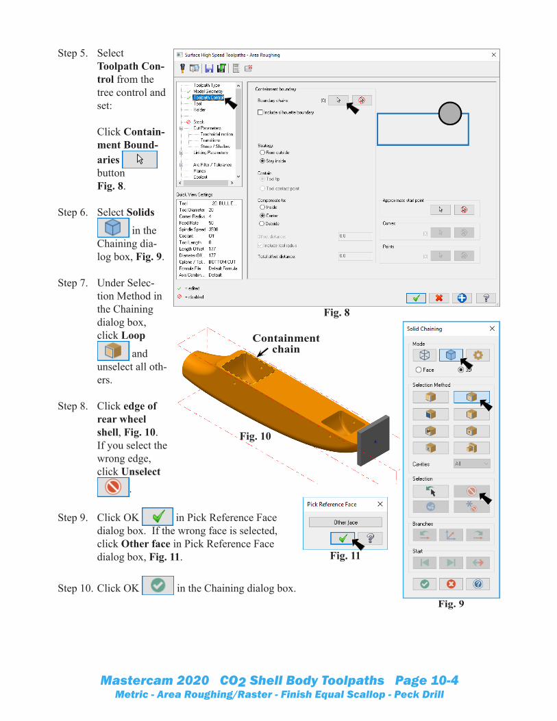
Step 5. Select Toolpath Con-trol from the tree control and set: Click Contain-ment Bound-aries button Fig. 8.
Step 6. Select Solids
in the Chaining dia-log box, Fig. 9.
Step 7. Under Selec-tion Method in the Chaining dialog box, click Loop
and unselect all oth-ers.
Step 8. Click edge of rear wheel shell, Fig. 10. If you select the wrong edge, click Unselect
.
Step 9. Click OK in Pick Reference Face dialog box. If the wrong face is selected, click Other face in Pick Reference Face dialog box, Fig. 11.
Step 10. Click OK in the Chaining dialog box.Fig. 9
Fig. 8
Fig. 11
Fig. 10
Containment chain

Mastercam 2020 CO2 Shell Body Toolpaths Page 10-5Metric - Area Roughing/Raster - Finish Equal Scallop - Peck Drill
Step 11. Back in Toolpath Con-trol page: Confirm 1 Boundary chain Compensate to Inside Uncheck Include tool radius Fig. 12.
Step 12. Select Tool from the tree control and: click Select library tool button Fig. 13.
Fig. 13
Fig. 12
Mastercam 2020 CO2 Shell Body Toolpaths Page 10-6Metric - Area Roughing/Raster - Finish Equal Scallop - Peck Drill
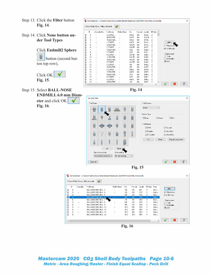
Step 13. Click the Filter buttonFig. 14.
Step 14. Click None button un-der Tool Types Click Endmill2 Sphere
button (second but-ton top row), Click OK Fig. 15.
Step 15. Select BALL-NOSE ENDMILL 6.0 mm Diam-eter and click OK Fig. 16.
Fig. 15
Fig. 14
Fig. 16

Mastercam 2020 CO2 Shell Body Toolpaths Page 10-7Metric - Area Roughing/Raster - Finish Equal Scallop - Peck Drill
Step 16. Back in Tool page set: Feed rate 300
Plunge rate 200 Fig. 17.
Step 17. Select Cut Pa-rameters from tree control and set: Cutting method Climb Stepdown 12.5 Keep tool down within % of tool diameter 500 XY stepover 50% Minimum 2 Maximum 3 Fig. 18.
Fig. 17
Fig. 18
Mastercam 2020 CO2 Shell Body Toolpaths Page 10-8Metric - Area Roughing/Raster - Finish Equal Scallop - Peck Drill
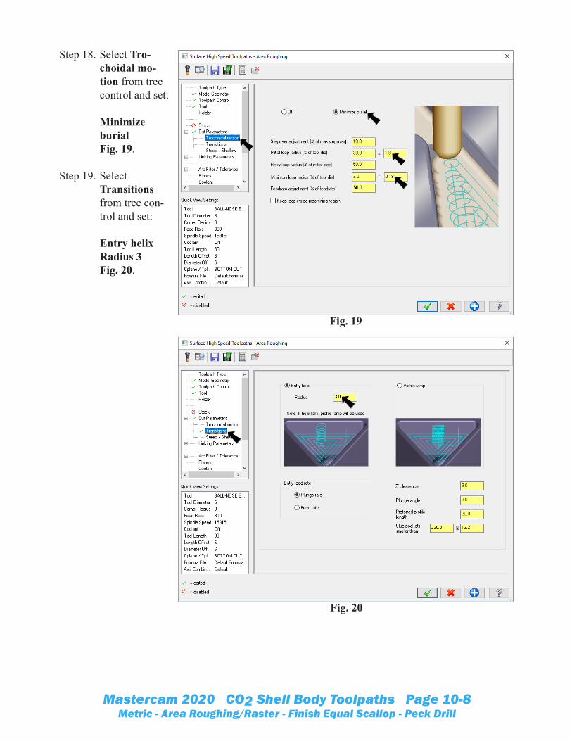
Step 18. Select Tro-choidal mo-tion from tree control and set: Minimize burialFig. 19.
Step 19. Select Transitions from tree con-trol and set: Entry helix Radius 3 Fig. 20.
Fig. 19
Fig. 20

Mastercam 2020 CO2 Shell Body Toolpaths Page 10-9Metric - Area Roughing/Raster - Finish Equal Scallop - Peck Drill
Step 20. Select Steep/Shallow from tree control and set: CheckMinimum depth -9 Check Maximum depth -35 Click Apply
Fig. 21.
Step 21. Select Linking Parameters from tree con-trol and set: Clearance plane 0 SelectMinimum Vertical Retract Part clearance 0 All Leads 0 Fig. 22.
Step 22. Click OK in Area
Roughing dia-log box.
Step 23. Allow Mastercam to calculate toolpath.
Step 24. Save (Ctrl-S).
Fig. 21
Fig. 22
Negative -9Negative -35
Mastercam 2020 CO2 Shell Body Toolpaths Page 10-10Metric - Area Roughing/Raster - Finish Equal Scallop - Peck Drill
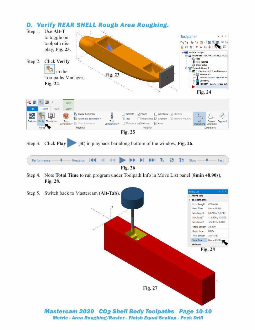
D. Verify REAR SHELL Rough Area Roughing.Step 1. Use Alt-T
to toggle on toolpath dis-play, Fig. 23.
Step 2. Click Verify
in the Toolpaths Manager, Fig. 24.
Step 3. Click Play (R) in playback bar along bottom of the window, Fig. 26.
Step 4. Note Total Time to run program under Toolpath Info in Move List panel (8min 48.90s), Fig. 28.
Step 5. Switch back to Mastercam (Alt-Tab).
Fig. 23
Fig. 26
Fig. 24
Fig. 25
Fig. 28
Fig. 27

Mastercam 2020 CO2 Shell Body Toolpaths Page 10-11Metric - Area Roughing/Raster - Finish Equal Scallop - Peck Drill
E. FRONT SHELL Area Roughing Surface Toolpath.Step 1. Use Alt-T to toggle off toolpath dis-
play.
Step 2. Copy Roughing toolpath in the Toolpaths Manager. To copy, click to select toolpath, Fig. 29. Then, use Ctrl-C and Ctrl-V, Fig. 30.
Step 3. Expand copied 2-Surface High Speed toolpath and click Param-eters, Fig. 30.
Step 4. Select Toolpath Control from tree control and set: Click Remove selected containment boundaries button Click Containment Boundaries buttonFig. 31.
Fig. 30
Fig. 29
Fig. 31

Mastercam 2020 CO2 Shell Body Toolpaths Page 10-12Metric - Area Roughing/Raster - Finish Equal Scallop - Peck Drill
Step 5. Select Solids
in the Chaining dialog box, Fig. 32.
Step 6. Under Selec-tion Method in the Chaining dialog box, click Loop
and unselect all others.
Step 7. Click edge of front wheel shell, Fig. 33.
Step 8. Click OK in Pick Reference Face dialog box. If the wrong face is selected, click Other face in Pick Reference Face dialog box, Fig. 34.
Step 9. Click the OK in the Chaining dialog box.
Step 10. Click OK in Area Roughing dialog box.
Step 11. In the Toolpaths Manager, click Regenerate all selected operations
, Fig. 35.
Step 12. Click the Toolpath Group-1 in the Toolpaths Manager to select both toolpaths, Fig. 36.
Step 13. Use Alt-T to toggle tool-path display.
Step 14. Save (Ctrl-S).
Fig. 32
Fig. 34
Fig. 33
Containment chain
Fig. 36Fig. 35
Fig. 37

Mastercam 2020 CO2 Shell Body Toolpaths Page 10-13Metric - Area Roughing/Raster - Finish Equal Scallop - Peck Drill
F. BOTH SHELLS Finish Raster Toolpath.Step 1. Use Alt-T to toggle off toolpath dis-
play.
Step 2. Copy the 2nd Area Roughing tool-path in the Toolpaths Manager. To copy, click to select 2nd toolpath, Fig. 38. Then, use Ctrl-C and Ctrl-V, Fig. 39.
Step 3. Expand the pasted 3-Surface High Speed and click Parameters, Fig. 39.
Step 4. Select Toolpath Type from the tree control and select: Finishing Raster Fig. 40.
Fig. 39
Fig. 38
Fig. 40

Mastercam 2020 CO2 Shell Body Toolpaths Page 10-14Metric - Area Roughing/Raster - Finish Equal Scallop - Peck Drill
Step 5. Select Model Geometry from the tree control and set: Wall Stock 0 Floor Stock 0 Fig. 41.
Step 6. Select Toolpath Con-trol from tree control and set: Under Contain select Tool contact point Click Contain-ment Bound-aries button Fig. 42.
Fig. 41
Fig. 42

Mastercam 2020 CO2 Shell Body Toolpaths Page 10-15Metric - Area Roughing/Raster - Finish Equal Scallop - Peck Drill
Step 7. Right click in the Chain manager dialog box and click Add from menu, Fig. 43.
Step 8. Select Solids in the Chaining dialog box and under Selection Method click Loop and unselect all others, Fig. 44.
Step 9. Click edge of rear wheel shell, Fig. 45.
Step 10. Click OK in Pick Reference Face dialog box, Fig. 46.
Step 11. Click the OK
in Chaining dialog box.
Step 12. Click OK in Chain
Manager dialog box, Fig. 47.
Fig. 44
Fig. 46
Fig. 45
Containment chain
Fig. 43
Fig. 47

Mastercam 2020 CO2 Shell Body Toolpaths Page 10-16Metric - Area Roughing/Raster - Finish Equal Scallop - Peck Drill
Step 13. Select Cut Pa-rameters from tree control and set: Cutting meth-od Zigzag Stepover .5 Fig. 48.
Step 14. Select Steep/Shallow from tree control and set: UncheckMinimum Uncheck Maximum Click Apply
Fig. 49.
Step 15. Click OK
inRaster dialog box.
Step 16. Save (Ctrl-S).
Fig. 48
Fig. 49

Mastercam 2020 CO2 Shell Body Toolpaths Page 10-17Metric - Area Roughing/Raster - Finish Equal Scallop - Peck Drill
G. Verify Wheel Shells.Step 1. In the Toolpaths Manager, click
Regenerate all selected operations , Fig. 50.
Step 2. Click Toolpath Group-1 to select all three shell toolpaths, Fig. 51.
Step 3. Click Verify in the Toolpaths Manager.
Step 4. Click Play (R) in playback bar along bottom of the window.
Step 5. Note Total Time to run program (31min 13.32s), Fig. 53.
Step 6. Switch back to Mastercam (Alt-Tab).
Fig. 51Fig. 50
Fig. 53
Fig. 52

Mastercam 2020 CO2 Shell Body Toolpaths Page 10-18Metric - Area Roughing/Raster - Finish Equal Scallop - Peck Drill
H. Rename Toolpath Group WHEEL SHELLS.Step 1. Rename Toolpath
Group-1 to WHEEL SHELLS in the Ops Man-ager. To rename, click and hover over Toolpath Group-1 then key-in WHEEL SHELLS, Fig. 54.
I. Insert LEFT CUT Toolpath Group.
Step 1. Insert new Toolpath group. To insert group, right click Ma-chine Group 1 at the very top of Ops Manager and click Groups > New Toolpath group, Fig. 55.
Step 2. Rename new Toolpath Group to LEFT CUT. To rename, click and hover over Toolpath Group-1 and key-in LEFT CUT, Fig. 56.
J. Switch to LEFT CUT WCS.Step 1. Display the Planes Manager. To display, click Planes tab
at the bottom of Ops Manager.
Step 2. In the Planes Manager set: under Name, Fig. 57 Click LEFT CUT Click Set All .
Step 3. Change to the Iso-metric View. Right click in the graphics window and click
(Alt-7).
Step 4. Confirm Left Cut Origin, Fig. 58. Use F9 to toggle axes.
Fig. 56
Fig. 54 Fig. 55
Right click
Fig. 57
LEFT CUT Origin
Fig. 58

Mastercam 2020 CO2 Shell Body Toolpaths Page 10-19Metric - Area Roughing/Raster - Finish Equal Scallop - Peck Drill
K. Left Cut Finish Equal Scallop Toolpath.Step 1. On the Toolpaths tab in the 3D
group click expand gallery button and click
Equal Scallop , Fig. 59.
Step 2. Select Model Geometry from the tree control and set: Under Machin-ing Geometry click Select en-
tities buttonFig. 60.
Step 3. Triple click the solid car body to select as machine geom-etry and click End Selection
(ENTER), Fig 61.
Fig. 59
Fig. 60
Fig. 61
Triple click solid car body

Mastercam 2020 CO2 Shell Body Toolpaths Page 10-20Metric - Area Roughing/Raster - Finish Equal Scallop - Peck Drill
Step 4. Back in Model Geometry page set: Wall Stock 0 Floor Stock 0 To set, double click and key-in. Under Avoid-ance Geom-etry click Select entities
buttonFig. 62.
Step 5. Triple click the check body to select as avoid-ance geometry, Fig 63.
Step 6. Rotate view to view bot-tom and rear surfaces, hold down middle mouse button (wheel) and drag to rotate view, Fig. 64.
Step 7. Click bottom and two rear surfaces to select as avoidance geometry and click End Selec-tion (EN-TER), Fig 64.
Fig. 62
Fig. 63
Triple click check solid
Fig. 64
Click bottom surface as avoidance geometry
Click both rear surfaces as avoidance
geometry

Mastercam 2020 CO2 Shell Body Toolpaths Page 10-21Metric - Area Roughing/Raster - Finish Equal Scallop - Peck Drill
Step 8. Back in Model Geometry page set: Confirm 9 Avoidance entities Fig. 65.
Step 9. Select Tool from tree con-trol and set: Feed rate 300
Plunge rate 200 Fig. 66.
Fig. 65
Fig. 66

Mastercam 2020 CO2 Shell Body Toolpaths Page 10-22Metric - Area Roughing/Raster - Finish Equal Scallop - Peck Drill
Step 10. Select Cut Pa-rameters from tree control and set: Cut styleBoth to Other Way Check Optimize cut order Stepover 1 Keep tool down within 100% Fig. 67.
Step 11. Select Steep/Shallow from tree control and set: CheckMinimum depth 0 Check Maximum depth -37 Click Apply
Fig. 68.
Fig. 67
Fig. 68
Negative -37

Mastercam 2020 CO2 Shell Body Toolpaths Page 10-23Metric - Area Roughing/Raster - Finish Equal Scallop - Peck Drill
Step 12. Select Linking Parameters from tree con-trol and set: Clearance plane 1 SelectMinimum Vertical Retract Part clearance 1 All Leads 0 Fig. 69.
Step 13. Select Arc Filter/Toler-ance from tree control and set: Total tolerance .0625 Check Line/Arc Filtering Settings Uncheck Cre-ate arcs in XY Check One way filtering Set Minimum arc radius .0625
Cut tolerance 10%Fig. 70.
Step 14. Click OK in Equal Scallop dialog box. Allow Mastercam to calculate toolpath , then Save (Ctrl-S).
Fig. 69
Fig. 70
Mastercam 2020 CO2 Shell Body Toolpaths Page 10-24Metric - Area Roughing/Raster - Finish Equal Scallop - Peck Drill
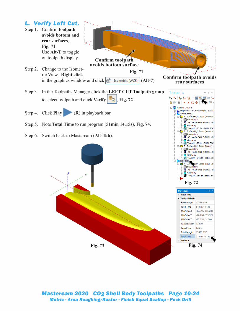
L. Verify Left Cut.Step 1. Confirm toolpath
avoids bottom and rear surfaces,Fig. 71.Use Alt-T to toggle on toolpath display.
Step 2. Change to the Isomet-ric View. Right click in the graphics window and click (Alt-7).
Step 3. In the Toolpaths Manager click the LEFT CUT Toolpath group
to select toolpath and click Verify , Fig. 72.
Step 4. Click Play (R) in playback bar.
Step 5. Note Total Time to run program (51min 14.15s), Fig. 74.
Step 6. Switch back to Mastercam (Alt-Tab).
Fig. 72
Fig. 74Fig. 73
Fig. 71
Confirm toolpath avoids bottom surface
Confirm toolpath avoids rear surfaces
Mastercam 2020 CO2 Shell Body Toolpaths Page 10-25Metric - Area Roughing/Raster - Finish Equal Scallop - Peck Drill
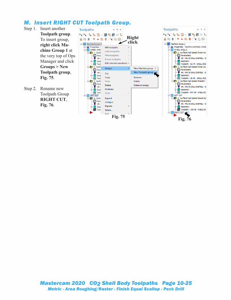
M. Insert RIGHT CUT Toolpath Group.Step 1. Insert another
Toolpath group. To insert group, right click Ma-chine Group 1 at the very top of Ops Manager and click Groups > New Toolpath group, Fig. 75.
Step 2. Rename new Toolpath Group RIGHT CUT, Fig. 76.
Fig. 75
Right click
Fig. 76
Mastercam 2020 CO2 Shell Body Toolpaths Page 10-26Metric - Area Roughing/Raster - Finish Equal Scallop - Peck Drill
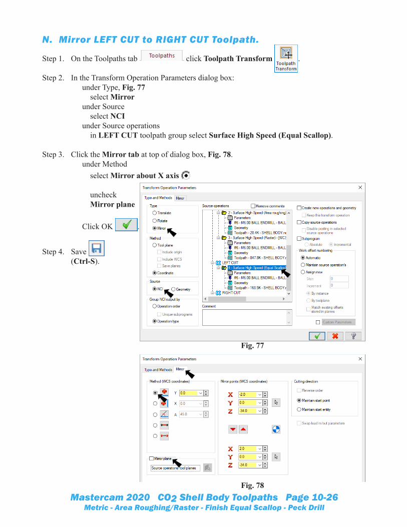
N. Mirror LEFT CUT to RIGHT CUT Toolpath.
Step 1. On the Toolpaths tab click Toolpath Transform .
Step 2. In the Transform Operation Parameters dialog box: under Type, Fig. 77 select Mirror under Source select NCI under Source operations in LEFT CUT toolpath group select Surface High Speed (Equal Scallop).
Step 3. Click the Mirror tab at top of dialog box, Fig. 78. under Method select Mirror about X axis uncheck Mirror plane Click OK .
Step 4. Save (Ctrl-S).
Fig. 78
Fig. 77

Mastercam 2020 CO2 Shell Body Toolpaths Page 10-27Metric - Area Roughing/Raster - Finish Equal Scallop - Peck Drill
O. Verify Right Cut.Step 1. In Toolpaths Manager, click
the Transform/Mirror tool-path, Fig. 80.
Step 2. Click Verify in Toolpaths Manager.
Step 3. Click Play (R) in play-back bar.
Step 4. Click Close to close Mastercam Simulation.
Fig. 79
Fig. 80Fig. 81
Mastercam 2020 CO2 Shell Body Toolpaths Page 10-28Metric - Area Roughing/Raster - Finish Equal Scallop - Peck Drill
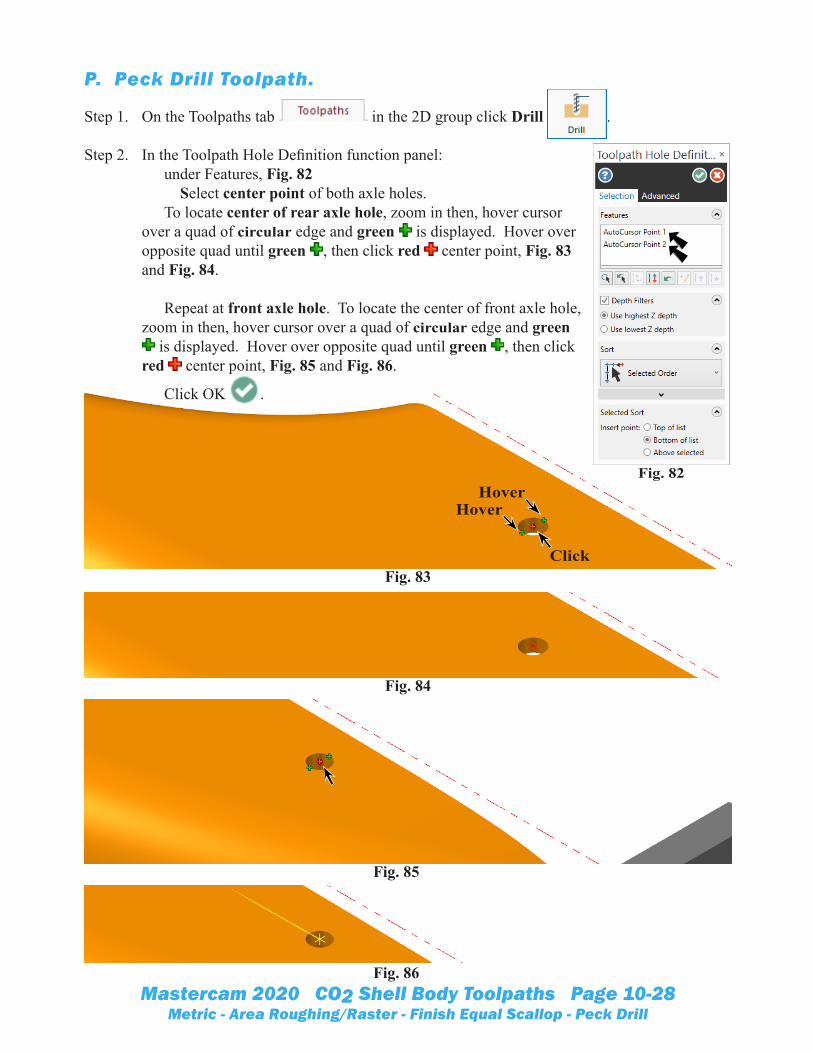
P. Peck Drill Toolpath.
Step 1. On the Toolpaths tab in the 2D group click Drill .
Step 2. In the Toolpath Hole Definition function panel: under Features, Fig. 82 Select center point of both axle holes. To locate center of rear axle hole, zoom in then, hover cursor over a quad of circular edge and green is displayed. Hover over opposite quad until green , then click red center point, Fig. 83 and Fig. 84. Repeat at front axle hole. To locate the center of front axle hole, zoom in then, hover cursor over a quad of circular edge and green
is displayed. Hover over opposite quad until green , then click red center point, Fig. 85 and Fig. 86.
Click OK .
Fig. 82
Fig. 85
Fig. 86
Fig. 83
Fig. 84
Click
HoverHover

Mastercam 2020 CO2 Shell Body Toolpaths Page 10-29Metric - Area Roughing/Raster - Finish Equal Scallop - Peck Drill
Step 3. In Toolpath page: Confirm 2 Points for geometry Fig. 87.
Step 4. Select Tool from the tree control and: Click Select library tool button Fig. 88.
Fig. 87
Fig. 88

Mastercam 2020 CO2 Shell Body Toolpaths Page 10-30Metric - Area Roughing/Raster - Finish Equal Scallop - Peck Drill
Step 5. Click the Filter buttonFig. 89.
Step 6. Click None button un-der Tool Types
Click Drill button Click OK Fig. 90.
Step 7. Sort by Diameter and select HSS DRILL 3 mm Diameter and click OK
Fig. 91.
Fig. 90
Fig. 89
Fig. 91
Mastercam 2020 CO2 Shell Body Toolpaths Page 10-31Metric - Area Roughing/Raster - Finish Equal Scallop - Peck Drill
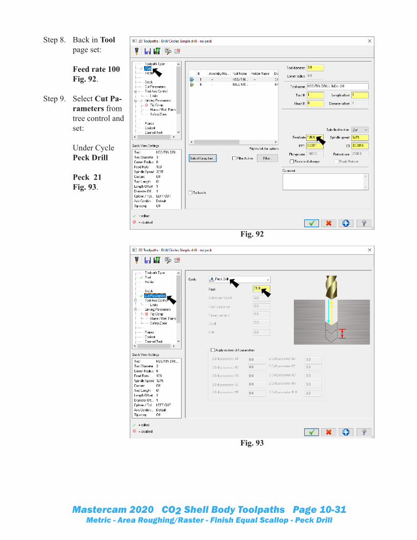
Step 8. Back in Tool page set: Feed rate 100 Fig. 92.
Step 9. Select Cut Pa-rameters from tree control and set: Under CyclePeck Drill Peck 21 Fig. 93.
Fig. 92
Fig. 93

Mastercam 2020 CO2 Shell Body Toolpaths Page 10-32Metric - Area Roughing/Raster - Finish Equal Scallop - Peck Drill
Step 10. Select Linking Parameters from tree con-trol and set: Uncheck Clearance Retract 1 Depth -55 Absolute (measures absolute values from the origin) Fig. 94.
Step 11. Click OK in Drill/
Circles Peck dialog box.
Step 12. Save (Ctrl-S).
Q. Backplot.Step 1. Change to Front View. Right click in the graphics window and
click (Alt-2).
Step 2. Use Ctrl-T to toggle Translucency on.
Step 3. Click Peck Drill toolpath in Toolpaths Manager, Fig. 95.
Step 4. Click Backplot in Toolpaths Manager.
Step 5. In the Backplot dialog box turn on Display Tool and Rapid Moves , Fig. 96.
Step 6. Click Play (R) in the Backplot playback bar.
Step 7. Click OK to close Backplot.
Fig. 94
Fig. 95
Fig. 97
Fig. 96