mastering the principle of radio network planning and
TRANSCRIPT

2013
Crystalfix Nig Ltd
Mastering the principle of RadioNetwork Planning and
Optimization(GSM/WCDMA)
2
What is Telecommunication?
Telecommunication is the transmission of signals over a distance for the purpose ofcommunication. Signals are transmitted in form of electromagnetic waves.
The Evolution of Mobile Telephone System Advance Mobile Phone System(AMPS) first deploy in North Americas in 1978. In 1990
D-AMPS took over. GSM and CDMA became the 'second generation' mobile phone systems in 1990s. GSM widely deployed in Europe while CDMA deployed in US and Asia market. Technology Improvement in Mid 1990 with Small phone, and Advanced Batteries
System. 1992 UK lunch SMS message on their GSM network followed in 1993 by the first
person-to-person SMS sent in Finland. In 1998 Supplementary services such as ring tone, access media, and advertisement
were implemented on the GSM platform. By 1999 exponential growth of mobile device. GSM took the largest share of the
mobile market. The first pre-commercial trial network with 3G was launched by NTT DoCoMo in Tokyo
Japan in 2001. Which began 3G (WCDMA) revolution? It was followed by CDMA2000 1xEV-DO.
During the development of 3G systems, 2.5G systems such as CDMA2000 1x and GPRS were developed as extensions to existing 2G networks.
In June of 2008, the Next Generation Mobile Networks Alliance (NGMN) selected LTE. This began the 4G revolution which has been deployed in America, Asia and Europe. Some Countries in Africa (Nigeria, S. Africa, Egypt) and Mideast are currently in deployment stateStandards Evolution
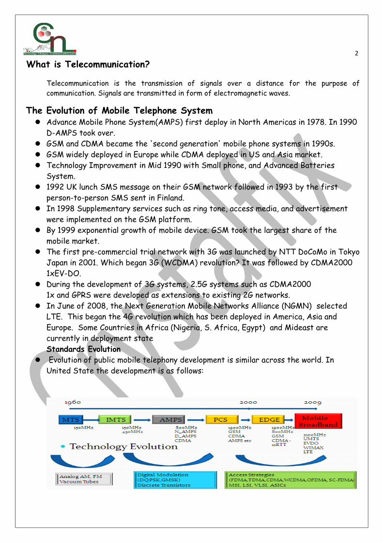
Evolution of public mobile telephony development is similar across the world. In United State the development is as follows:

3 System Capacity Evolution
System capacity have exponentially grown. The evolution of mobile broadband will bring in new data services and high data useage:
1982- GSM (Groupe Speciale Mobile) is formed by Confederation of European Posts Telecommunications (CEPT) to design a pan European mobile technology.
1985 – European Commission endorse GSM Project 1986- 900MHz spectrum band was reserve for GSM by the EC Telecommunication
council. France, Germany, Italy and UK on standard and MOU was signed by 15 members from 13 European countries.
1989- Groupe Speciale Mobile was define the GSM standard as the internationally accepted digital cellular telephony standard.
1990- GSM adaptation work started for DCS1800 band. 1991- The first GSM call was made in Finland. 1992 to 1995- GSM with SMS feature was deployed and roaming agreement between
some European telecom companies. DCS1800 GSM network was opened in UK. 1995- GSM global subscriber exceed 10 million and first North America PCS 1900 was
opened in US. 1996 to 1999 – GSM network has spread to over 100 countries. GSM subscriber has
surpass 100 million and WAP trial begin in France and Italy to launch GPRS. 2000 to present- GSM evolve to GPRS/EDGE due to increase in data usage. By 2001
WCDMA network goes live in France. LTE uses Orthogonal Frequency Division Multiple Access (OFDMA) on the downlink,
which is well suited to achieve high peak data rates in high spectrum bandwidth. WCDMA radio technology is, essentially, as efficient as Orthogonal Frequency DivisionMultiplexing (OFDM) for delivering peak data rates of about 10 Mbps in 5 MHz of bandwidth. Achieving peak rates in the 100 Mbps range with wider radio channels,

4however, would result in highly complex terminals and is not practical with current technology. This is where OFDM provides a practical implementation advantage.
The OFDMA approach is also highly flexible in channelization, and LTE will operate in various radio channel sizes ranging from 1.4 to 20 MHz. LTE also boosts spectral efficiency.
On the uplink, however, a pure OFDMA approach results in high Peak to Average Ratio (PAR) of the signal, which compromises power efficiency and, ultimately, battery life. Hence, LTE uses an approach for the uplink called Single Carrier FDMA (SC-FDMA), which is somewhat similar to OFDMA, but has a 2 to 6 dB PAR advantage over the OFDMA method used by other technologies such as WiMAX IEEE 802.16e.
LTE capabilities include: Downlink peak data rates up to 326 Mbps with 20 MHz bandwidth Uplink peak data rates up to 86.4 Mbps with 20 MHz bandwidth Operation in both TDD and FDD modes Scalable bandwidth up to 20 MHz, covering 1.4 MHz, 3 MHz, 5 MHz, 10 MHz, 15 MHz,
and 20 MHz in the study phase Increased spectral efficiency over Release 6 HSPA by two to four times Reduced latency, up to 10 milliseconds (ms) round-trip times between user equipment
and the base station, and to less than 100 ms transition times from inactive to active
Generations of Telecom
NMT-Nordic Mobile telephony TACS – Total Access Communication System AMPS-Advanced Mobile

5
Phone Systems GSM-Global System for Mobile Communication GPRS-General Packet Radio System
EDGE-Enhanced Data Rate for GSM Evolution TDMA-Time Division Multiple Access CDMA-Code
Division Multiple Access WCDMA-Wideband Code Division Multiple Access TD-SCDMA-Time Division
Synchronous Code Division Multiple Access HSPA-High Speed Packet Access HSUPA – High Speed
Uplink Packet Access HSDPA-High Speed Downlink Packet Access LTE-Long term Evolution

6
Limitations of analog systems
• Incompatibility – NMT Mobile equipment could not call or
communicate with AMPS Mobile equipment.
• Insufficient capacity – the number of subscribers exceeded the
network.
• Limited equipment market

7
MODES OF COMMUNICATION • Simplex Mode – signal travels in one direction alone. It is a point to multipoint mode of
communication. E.g. radio and TV stations
• Half Duplex – signal is propagated to and fro along one frequency. E.g. Walkie talkie
• Full Duplex – signals are propagated to and fro but along different frequency channels.
Radio Access Technique (RAT) The Multiple Access Technique allows many subscribers to use the same communication medium.
Types of MAT 1.
FDMA sometimes called channelization, means dividing the whole available spectrum into many single radio channels (transmit/receive carrier pair). The whole frequency spectrum available is divided into many individual channels (for transmitting and receiving), every channel can support the traffic for onesubscriber or some control information. Each frequency channel used for transmission and reception ofsignals is 0.2MHz away from the next adjacent channel.
2.
• Time Division Multiple Access means that the wireless carrier of one bandwidth is divided into multiple time division channels in terms of time (or called timeslot). Each user occupies a timeslot and receives/transmits signals within this specified timeslot.

8
3.
loose nothing after being mixed and transmitted together on the same frequency and at thesame time.
• CDMA can transmit the information of multiple users on a channel at the same time. Mutualinterference between users is permitted.
FREQUENCY ALLOCATION IN CDMA
Band Class 0 and Spreading Rate 1 For Base Station is: F=825+N*0.03
Where N: CDMA Channel NumberThe interval between the Forward and Reverse link is 45MHz
Band Class 1 and Spreading Rate 1
The interval between the Forward and Reverse link is 80MHz The transmit frequency for the Base station is calculated by: F=1930+N*0.05
The GSM Frequency Spectrum

9
Duplex Separation: 45MHz Channel Bandwidth: 200 KHz ARFCN: F (n) = 890 + 0.2n
Duplex Separation: 95MHz Channel Bandwidth: 200 KHz ARFCN: F (n) = 1710.2 + (n -512)
Duplex Separation: 190MHzChannel spacing: 5MHzARFCN: n = 5 * (Frequency in MHz)
Uplink–Frequency that propagates signals from the MS to the BTS
Downlink–Frequency that propagates signals from the BTS to the MS
Duplex Separation–the distance between the uplink frequency and the corresponding downlink frequency.
Channel bandwidth– the distance between adjacent carrier frequencies in the UL &
DL frequencies. It is needed to reduce interference.

10 ARFCN–Absolute Radio Frequency Channel Number: No. assigned to an already existing
frequency channel
UARFCN–UMTS Absolute Radio Frequency Channel Number: No. assigned to an already existing frequency channel on WCDMA Networks.
EARFCN–E-ULTRAN Absolute Radio Frequency Channel Number: No. assigned to an already existing frequency channel on LTE Networks
Guard Band- This is a spared(unused frequency)for an operator(either the start or the end frequency)
Assignment 1: Find out the frequency range, frequency bandwidth, and Duplex seperation for GSM 1900 and LTE Network.
MOBILE NETWORK RELATED IDENTITIES
MOBILE STATION MS = ME + SIM ME = Mobile Equipment SIM = Subscriber Identity Module
SIM REALATED IDENTITIES

11
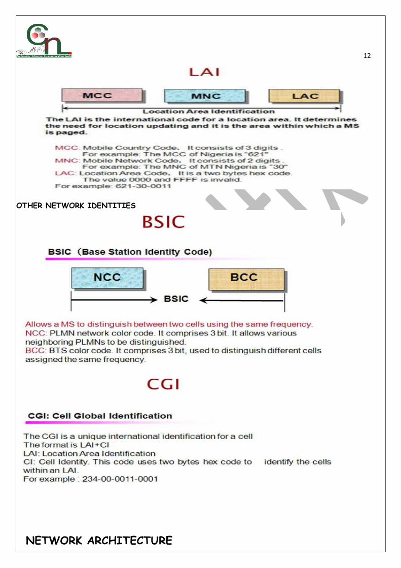
12
OTHER NETWORK IDENTITIES
NETWORK ARCHITECTURE
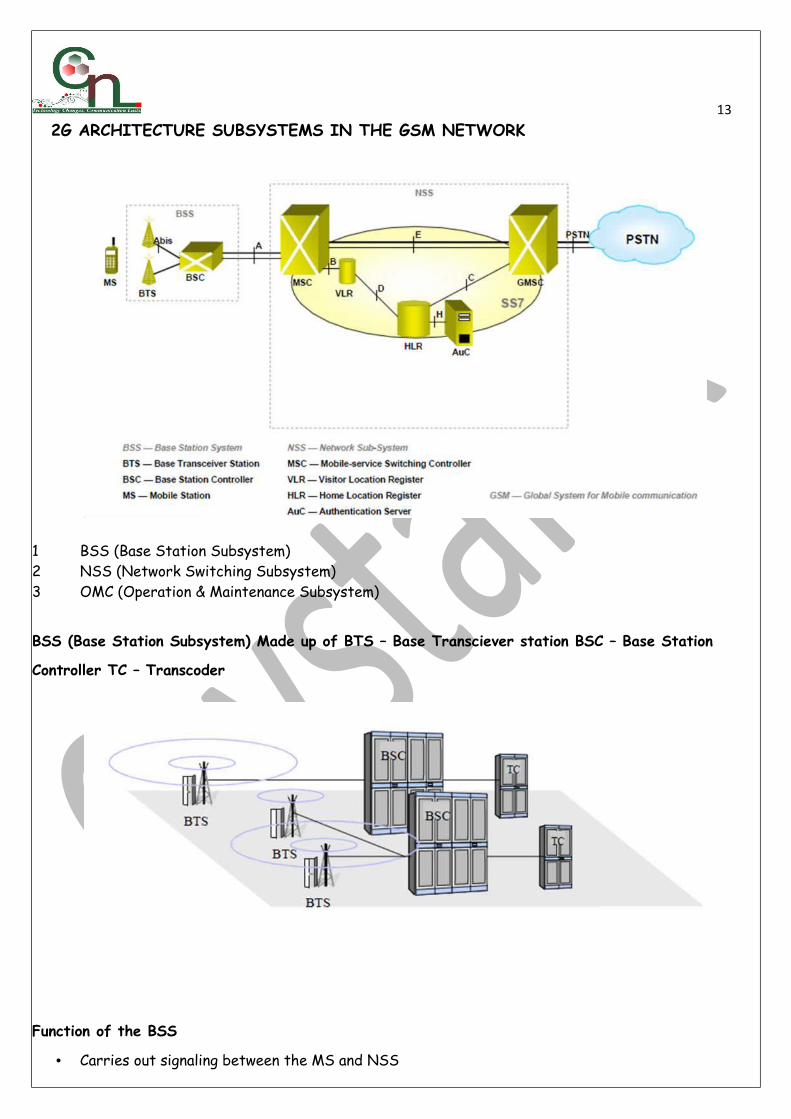
13 2G ARCHITECTURE SUBSYSTEMS IN THE GSM NETWORK
1 BSS (Base Station Subsystem) 2 NSS (Network Switching Subsystem) 3 OMC (Operation & Maintenance Subsystem)
BSS (Base Station Subsystem) Made up of BTS – Base Transciever station BSC – Base Station
Controller TC – Transcoder
Function of the BSS
• Carries out signaling between the MS and NSS

14• Handles traffic Carries out transcoding of speech signal
• Allocates radio channels to MS
Function of the BTS • Minimizing transmission problems • Ciphering • Speech processing • Maintaining the air interface
Function of the BSC • Establish connection between MS and NSS • Mobility Management • Collects information from the BTS, Transcoders and forwards it to the OSS • BTS and TC control
Function of the TC • For efficient transmission of speech over the air interface, the digital speech must be
compressed.For transmission over the air interface, the speech signal is compressed by the MS to13kbps (Full rate or enhanced full rate), or 5.6kbps (Half rate)The standard bit rate for speech is PSTN is 64kbps.

15NSS (Network Switching Subsytem)
• Call Control -Call setup and routing of the callsAllocation of access resourcesMobility Management -Location registrationInitiation of pagingReallocation of frequencies to BTSs in its areaCharging -Billing for all subscribers based in its area
• Function of VLR
• Database that stores information about subscribers currently being in the service area of theMSC.
• Information stored includes;1. Mobile Status (IMSI attached / detached / busy / idle etc.)2. Location Area Identity(LAI)3. Temporary Mobile Subscriber Identity(TMSI)4. Allocating the Roaming Number
Function of HLR
• Database that stores all the data of all subscribers available to a specific operator Information stored include;
1. Current subscriber VLR (current location)
2. Subscriber ID (IMSI and MSISDN)
3. Supplementary service information

164. Subscriber status (registered/deregistered)
5. Authentication key and AuC functionality
Function of AUC
• Provides security information to the network, so that we can verity the SIM cards (authentication between the MS and the VLR, ciphering the information transmitted in the air interface (between the MS and the BTS).
Function of EIR
• White List -contains list of IMEIs known to have been assigned to valid MSs.
• Black List -contains IMEIs that have been reported stolen/it is not allowed to operatewithin the network
• Grey List – contains IMEIs of MEs with faults not important enough for barring.
2.5G ARCHITECTURE
• Gb -Between the PCUSN Relay. • Gr -Between SGSN and Application Part (MAP). • Gn -Between SGSN and GGSN, the GTP (tunneling) protocol. • Gi -Between GGSN and PDNs (X.25 and Internet Protocol [IP]). • Gs -Between SGSN and MSC/VLR, for some simultaneous GPRS and GSM operations.

17• Gd -Delivers SMS messages via GPRS (same as MAP from GSM). Gc -Between GGSN and HLR.
Note;To understand GPRS system architecture it is helpful to first understand architecture of GSM system. . GPRS is an enhancement over the GSM and adds some nodes in the network to provide the packet switched services. These network GSNs (GPRS Support Nodes) and are responsible for the routing and delivery of the data packets to and from the MS and external packet data networks (PDN).
Network Addition of two network elements:Serving GPRS Support Node (SGSN)
Function: • Ciphering of GPRS data between the MS and SGSN
• Authentication of GPRS users
• Mobility Management
• Routing of data to the relevant GGSN when a connection to an external network is made Interaction with the NSS
• Collection of charging data
Gateway GPRS Support Node (GGSN) Function: • Routing Mobile destinated packets coming from external network to the relevant SGSN • Deals with security issues, interfaces to external IP Networks
Collects data and traffic statistics
GPRS BSS A software upgrade is required Transceiver Site (BTS). The Base Station Controller (BSC) also requires a software upgrade, and the installation of a new pieceof hardware called a packet control unit (PCU). The PCU directs the data traffic to the GPRS can be a separate hardware element associatedwith BSC. The PCU provides a physical and logical data interface out of BSS for packet data traffic.

183G ARCHITECTURE
GSM Network Geographic Area and Number Identities.
• Cell: A cell is the smallest area within a GSM network served by a BCCH.
• Location area: Location areas are comprised of one or several radio cells. Each location area is given an unique number within the network, the Location Area Code (LAC);This codeis used as a unique reference for the location of a mobile subscriber. This code is necessary to address the subscriber in the case of an incoming call.
The LAC forms part of the Location Area Identifier (LAI) and is broadcasted on the Broadcast Control Channel(BCCH).
• MSC Service Area: It consists of many Location area differentiated by a unique LAC.
• PLMN Service Area: This is an area within a cellular network that consists of one or more operators. Its uses a unique identifier,MNC to differentiate between each operators in the PLMN network.

19
GSM Network Geographic Area and Number GSM Network Geographic Area and Number
Remember;

20
GSM Characteristics Specifications for different Personal Communication Services (PCS) systems vary among the different PCS networks. The GSM specification is listed below with important characteristics.
• Modulation is a form of change process where we change the input information into a suitable format for the transmission medium. We also changed the information by demodulating the signal at the receiving end. The GSM uses Gaussian Minimum Shift Keying(GMSK) modulation method.
• Access Methods: Because radio spectrum is a limited resource shared by all users, a method must be devised to divide up the bandwidth among as many users as possible.GSM chose a combination of TDMA/FDMA as its method. The FDMA part involves the division by frequency of the total 25 MHz bandwidth into 124 carrier frequencies of 200 kHz bandwidth.
One or more carrier frequencies are then assigned to each BS. Each of these carrier frequencies is then divided in time, using a TDMA scheme, into eight time slots. One time slot is used for transmission by the mobile and one for reception. They are separated in time so that the mobile unit does not receive and transmit at the same time.
Transmission Rate: The total symbol rate for GSM at 1 bit per symbol in GMSK produces 270.833 K symbols/second. The gross transmission rate of the time slot is 22.8 Kbps.
GSM is a digital system with an over-the-air bit rate of 270 kbps. Frequency Band:The uplink frequency range specified for GSM is 933 - 960 MHz (basic
900 MHz band only). The downlink frequency band 890 - 915 MHz (basic 900 MHz band only).
Channel Spacing:This indicates separation between adjacent carrier frequencies. In GSM, this is 200 kHz.
21 Speech Coding:GSM uses linear predictive coding (LPC). The purpose of LPC is to reduce
the bit rate. The LPC provides parameters for a filter that mimics the vocal tract. The signal passes through this filter, leaving behind a residual signal. Speech is encoded at 13 kbps.
Duplex Distance:The duplex distance is 80 MHz. Duplex distance is the distance between the uplink and downlink frequencies. A channel has two frequencies, 80 MHz apart.
Frame duration: 4.615 mS Duplex Technique: Frequency Division Duplexing and Time Division Multiple access
(FDD/TDMA). Speech channels per RF channel: 8.
GSM Interfaces The Air interface is the wireless medium for carrying the user voice & data from MS to
BTS, hence it has to be an open interface to be able to support MS produced by various manufacturers.
The Abis interface is generally a wireless (microwave) or a wired (Copper/fiber optic) medium between BTS to BSC, the type of medium to be used depends on the capacity (Mbps) the link has to carry and also considering future expansion of the network. It is a proprietary interface i.e. the BTS & BSC should be from the same manufacturer to be ableto understand the signalling as well as traffic that is to be routed.
The next is the Ater interface between BSC to TCSM which is again proprietary as the BSC & the Transcoder should be compatible to each other to be able to understand each other. Generally the medium is a high capacity Fiber optic link using SDH Technology.
The A interface is between TCSM & MSC which again is an open interface, as the individual user info is to be converted to PSTN compatible 64Kbps rate. As for a large number of users there would be a large number of cables required between TCSM & MSC hence to minimize the cabling cost the TCSM is kept at the MSC.
GSM Physical/Logical Channels Physical Channels: It is a medium over which the information is carried at 200Khz and
0.577ms burst time (a burst is an information carried on one time slot). Time Division multiple access(TDMA) divides one Khz radio frequency channel into consecutive periods oftime, each one called a“TDMA frame". Each TDMA frame contains eight shorter periods of time called“timeslots”.These timeslots are called “Physical channels” since they are usedto physically move information from one place to another.
Logical Channels: It consists of the information carried on the physical channel. The contents of the physical channels are called the logical channels. They consist of the information carried on the physical channels.

22
Logical Channels are divided into two types; Traffic channels and Control Channelso Traffic Channels (TCH);TCH carries speech or subscriber data.
TCH provides the logical resources for the voice and data traffic that is exchanged over the network.
They contain general information about the network and the broadcasting cell. There are three types of BCH.
1. Broadcast Control Channel (BCCH) -Contains information detailed network and cell specific information such as: } Frequency used in the particular cells and neighboring cells } Frequency hopping sequence –designed to reduce the negative effect of the air interface that can sometimes result in loss of information. The may transmit information on different frequencies in one cell. The order in which the MS should change the frequencies is known as “frequency hopping sequence” Channel combination – all logical channels are mapped intotimeslot 0 or 1. The channel combination informs the MS on the mapping method of cannels on each cell. Paging groups – there is more than one paging cannel in one cell. Paging groups help prevent a MS from listening to all the paging channels for a paging message by dividing the paging channels in such a way that only a group of MS listens to a particular paging channel. These are referred to as paging groups. Information on surrounding cells –a MS has to know what the cells surrounding the serving cellare and the frequencies they broadcast since it has to constantly measure the signal strength and quality of the surrounding cells.

231 Frequency correction channel (FCCH) – the MS scans for this signal after it has been switched on since it has no information as to which frequency to use. 2 SCH contains the BSIC. The BSIC is needed to identify that the frequency strength beingmeasured by the MS is coming from a particular BS. It allows the MS to synchronize with the TDMA frame and for BTS identification.
Common Control channel (CCCH) The CCCH is responsible for transferring control information between all mobiles and the network. They are used to setup a point to point connection. There are three types of CCCH 1 Paging Channel (PCH) – a downlink channel that is broadcast by all BTS of a LA in the case of a mobile terminated call. 2 Random Access channel (RACH) – an uplink channel used by the MS to request for network resources e.g. Voice call, packet services. 3 Access grant Cannel – a downlink channel used by the network to answer a RACH application.
Dedicated Control Channel DCCH is assigned to MS to enable it to conduct point-to-point signaling transmission with BTS. There are three types of DCCH 1 Stand Alone Dedicated Control Channel (SDCCH) – for call set up, authentication, location update, assignment of traffic channel and transmission of short messages. 2 Slow Associated Control channel – transmits measurement reports and is used for power control. 3 Fast Associated Control Channel – is used when a handover is required. It is mapped unto a TCH. Also makes multiple calls possible
MODES OF MS The MS can exist in two modes
1 A ttached Mode Idle mode – MS is powered on but not in use (the MS is not assigned any DCCH) Active/Dedicated mode – MS is in use. It is assigned a DCCH 2 Detached Mode – MS is switched or powered off
Mapping of Logical Channels
Basically, GSM logical channels are mapped as below, several changes can be made in form of addition when the need for Data and capacity expansion arise.

24
Data Frame Numbering GSM frame structure uses slots, frames, multiframes, superframes and hyperframes to
give the required structure and timing to the data transmitted. The GSM system has a defined GSM frame structure to enable the orderly passage of
information. The GSM frame structure establishes schedules for the predetermined use of timeslots. By establishing these schedules by the use of a frame structure, both the mobile and the base station are able to communicate not only the voice data, but also signaling information without the various types of data becoming intermixed and both endsof the transmission knowing exactly what types of information are being transmitted. The GSM frame structure provides the basis for the various physical channels used within GSM, and accordingly it is at the heart of the overall system.
Basic GSM frame structure The basic element in the GSM frame structure is the frame itself. This comprises the eight slots, each used for different users within the TDMA system. As mentioned in another page of the tutorial, the slots for transmission and reception for a given mobile are offset in time so that the mobile does not transmit and receive at the same time.
GSM frame consisting of eight slots The basic GSM frame defines the structure upon which all the timing and structure of the GSM messaging and signalling is based. The fundamental unit of time is called a burst period and it lasts for approximately 0.577 ms (15/26 ms). Eight of these burst periods are grouped into what is known as a TDMA frame. This lasts for approximately 4.615 ms (i.e.120/26 ms) and it forms the basic unit for the definition of logical channels. One physical channel is one burst

25period allocated in each TDMA frame.
In simplified terms the base station transmits two types of channel, namely traffic and control. Accordingly the channel structure is organized into two different types of frame, one for the traffic on the main traffic carrier frequency, and the other for the control onthe beacon frequency.
GSM multiframe The GSM frames are grouped together to form multiframes and in this way it is possible to establish a time schedule for their operation and the network can be synchronized.
There are several GSM multiframe structures: Traffic multiframe: The Traffic Channel frames are organized into multiframes
consisting of 26 bursts and taking 120 ms. In a traffic multiframe, 24 bursts are used for traffic. These are numbered 0 to 11 and 13 to 24. One of the remaining bursts is then usedto accommodate the SACCH, the remaining frame remaining free. The actual position used alternates between position 12 and 25.
Control multiframe: the Control Channel multiframe that comprises 51 bursts and occupies 235.4 ms. This always occurs on the beacon frequency in time slot zero and it mayalso occur within slots 2, 4 and 6 of the beacon frequency as well. This multiframe is subdivided into logical channels which are time-scheduled. These logical channels and functions include the following: Frequency correction burst ,Synchronisation burst ,Broadcast channel (BCH),Paging and Access Grant Channel (PACCH) ,Stand Alone Dedicated Control Channel (SDCCH)
GSM Superframe:Multiframes are then constructed into superframes taking 6.12 seconds. These consist of 51 traffic multiframes or 26 control multiframes. As the traffic multiframes are 26 bursts long and the control multiframes are 51 bursts long, the different number of traffic and control multiframes within the superframe, brings them back into line again taking exactly the same interval.
GSM Hyperframe:Above this 2048 superframes (i.e. 2 to the power 11) are grouped to form one hyperframe which repeats every 3 hours 28 minutes 53.76 seconds. It is the largest time interval within the GSM frame structure.
Within the GSM hyperframe there is a counter and every time slot has a unique sequential number comprising the frame number and time slot number. This is used to maintain synchronisation of the different scheduled operations with the GSM frame structure. These include functions such as:
Frequency hopping: Frequency hopping is a feature that is optional within the GSM system. It can help reduce interference and fading issues, but for it to work, the transmitter and receiver must be synchronised so they hop to the same frequencies at thesame time.
Encryption: The encryption process is synchronised over the GSM hyperframe period where a counter is used and the encryption process will repeat with each hyperframe. However, it is unlikely that the cellphone conversation will be over 3 hours and accordingly it is unlikely that security will be compromised as a result.

26
The frame structure might be depicted as follows: 1 Frame =1250bits GMSK symbol= 2 bitsTotal symbols= 625 Symbols625 symbols occupies = 4.615 ms long.Consist of 8 time slots (0-7)1 slot =156.25bits
TRAFFIC CASES
IMSI DetachIMSI AttachLocation UpdateImplicit DetachPagingHandoverCell reselection
GSM Mobility Management IMSI Attach
When an MS is switch on, the IMSI attach procedure is executed. This involves the following steps:
1. The MS sends an IMSI attach message to the network indicating that it has change state to idle.
2. The VLR determines whether there is a record for the subscriber already present. If not the VLR contacts the subscriber’s HLR for a copy of subscription information.
3. The VLR updates the MS status to idle. 4. Acknowledgement is sent to the MS.
If the MS has change LA while powered off, the IMSI attach procedure may lead to an update to the location of MS. During IMSI attach, the VLR may determine that the current LAI of the MS is different from the LAI stored in the MS’s subscription information. If so, the VLR updates the LAI of the MS

27 IMSI Detach
IMSI detach enables the MS to indicate to the network that it is switch off. At poweroff, the MS sends an IMSI detach message to the network. On reception, the VLR marks the corresponding IMSI as detached. The HLR is not informed. No acknowledgement is sent to the MS. If the radio link quality is poor, the system might not be able to decode the information. Because no acknowledgement is sent to the MS, no further attempt is made. In this case, the system still regards the MS as attached. If the periodic registration is in use the system will eventually determine that the MS is detached. The VLR then performs an implicit detach, marking the MS as detached.
• A GSM mobile is in idle mode when the MS is switched ONand there is no dedicated connection. Idle mode management is necessary for mobile to camp on the best suitable cell just ;
For MS to receive system info from the NW on DL For MS to be able to initiate a call whenever needed For the NW to be able to locate the MS when there is a MT call/SMS• Idle Mode Tasks includes; PLMN selection, Cell selection and reselectionLocation update
Radio Power MeasurementdBm definition;dBm or decibel-milliwatt is an electrical power unit in decibels(dB),
referenced to 1 milliwatt (mW).The power in decibel-milliwatts (P(dBm)) is equal to the base 10 logarithm of the power
in milliwatts (P(mW)):P(dBm) = 10 · log10( P(mW) / 1mW )
dBs are brilliant and fun and make radio and signal level calculations a lot easier. Read herefor an explanation plus a handy calculator which will convert dB values into watts and vice versa.
In radio communications you have many items (amplifiers, attenuators, signal splitters and combiners, lossy cables etc) that either increase or decrease the signal level. To work out the end result for a signal going through a chain of such devices you use the dB gain or dB attenuation of each device and simply add all the dB values together.
Simple Dbm to watt conversion P(dBm) = 30+10logP(watt)
28
Antenna Basic Principles
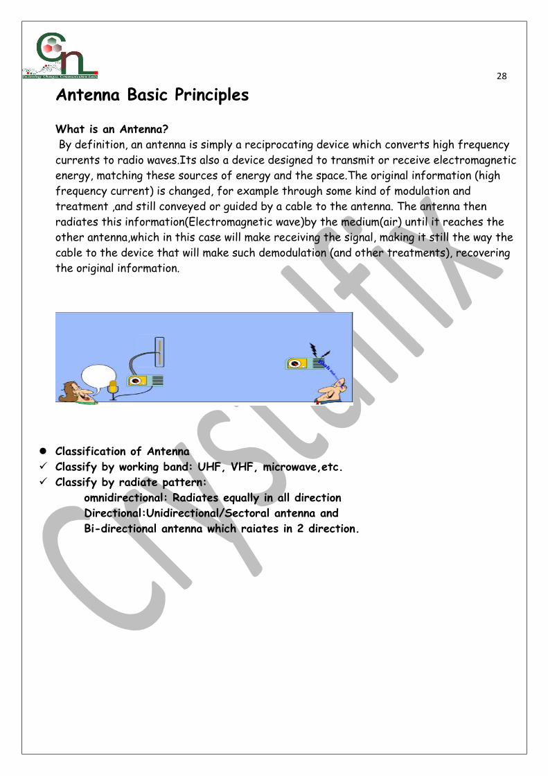
What is an Antenna? By definition, an antenna is simply a reciprocating device which converts high frequency currents to radio waves.Its also a device designed to transmit or receive electromagnetic energy, matching these sources of energy and the space.The original information (high frequency current) is changed, for example through some kind of modulation and treatment ,and still conveyed or guided by a cable to the antenna. The antenna then radiates this information(Electromagnetic wave)by the medium(air) until it reaches the other antenna,which in this case will make receiving the signal, making it still the way the cable to the device that will make such demodulation (and other treatments), recovering the original information.
Classification of Antenna Classify by working band: UHF, VHF, microwave,etc. Classify by radiate pattern:
omnidirectional: Radiates equally in all direction Directional:Unidirectional/Sectoral antenna and Bi-directional antenna which raiates in 2 direction.

29
Antenna Propagation A useful abstraction in the study of antennas is the isotropic radiator, which is an ideal antenna that radiates (or receives) equally in all directions, with a spherical pattern. The isotropic radiator is also sometimes called an omni-directional antenna, but this term is usually reserved for an antenna that radiates equally in all directions in one plane, such as a whip antenna, which radiates equally over azimuth angles but varies with elevation. Thepower density, S, due to an isotropic radiator is a function only of the distance, d, from the antenna and can be expressed as the total power divided by the area of a sphere with radius d.
That is, the power is uniformly distributed over the sphere. Thus for an isotropic radiator,the power density at a given range is constant over all angles and is equal to the average power density at that range. For a real antenna, there will be certain angles of radiation, which provide greater power density than others (when measured at the same range). The directivity of an antenna is defined as the ratio of the radiated power density at distance, d, in the direction of maximum intensity to the average power density over all angles at distance, d. This is equivalent to the ratio of the peak power density at distance d, to the average power density at d:
Antenna Gain Antenna Gain: This can be measured in terms of dipole and isotropic. Dipole radiates in 2 directions while isotropic radiates in all direction.

30 Antenna gain: dBi=dBd + 2.15dB Isotropic gain is 2.15 more than dipole gain Note: >16dBi ---- High gain , 14dBi – 16dBi ---- Medium gain , <13dBi----Low gain
Gain The radiation ability of certain antenna overlap dipole or isotropic. Indicates the antenna feauture of electrommagnetic radiation in a specific direction. Antenna Polarization Polarization is defined as the orientation of the plane that contains the electric field
component of the radiated waveform. In many cases, the polarization of an antenna can be determined by inspection. For instance, a vertical whip antenna generates and receives vertical polarization. Similarly, if the antenna element is horizontal, the wave polarization will be horizontal. Vertical and horizontal polarizations are both considered linear polarizations. Another type of polarization is circular or elliptical polarization. Circular polarization is similar to linear polarization, except that the polarization vector rotates either clockwise or counterclockwise, producing right-hand circular or left-hand circular polarization. Circular polarization is a special case of elliptical polarization, where the vertical and horizontal components of the polarization vector are of equal magnitude. In general, aperture antennas can support vertical, horizontal, or elliptical polarization, depending upon the type of feed that is used.
Vertical polarization antennas (also called mono-polarization antennas) Cross polarization antennas (also called dual polarization antennas).
Antenna Propagation Horizontal polarization antennas
Radiation Pattern Vertical and Horizontal pattern of an antenna is as below

31
Front to Back ratio: Front to back ratio of an isotropic antenna is 1.If FB ratio of a directional antenna is high ,that means the front lobe has much value than the Back.This kind of antenna are normally used in urban/suburban areas in order to avoid interference(with back lobe)
Non Zero field(Null Field): Its used to control under tower effect.High gain antenna especially adopt Null field technology to effectively improve nearby coverage. i.e It shall apply null field technology when zero depth is less than main beam for 26dB.
Beam width: See the polar radiation picture(PRP).
The main beam is the region around the direction of maximum radiation (usually the region that is within 3 dB of the peak of the main beam). The main beam in PRP is centered at 90 degrees.
The sidelobes are smaller beams that are away from the main beam. These sidelobes are usually radiation in undesired directions which can never be completely eliminated. The sidelobes in PRP occur at roughly 45 and 135 degrees.
The Half Power Beamwidth (HPBW) is the angular separation in which the magnitude of theradiation pattern decrease by 50% (or -3 dB) from the peak of the main beam. From PRP, the pattern decreases to -3 dB at 77.7 and 102.3 degrees. Hence the HPBW is 102.3-77.7 = 24.6 degrees.
Another commonly quoted beamwidth is the Null to Null Beamwidth. This is the angular separation from which the magnitude of the radiation pattern decreases to zero (negative infinity dB) away from the main beam. From PRP, the pattern goes to zero (or minus infinity) at 60 degrees and 120 degrees. Hence, the Null-Null Beamwidth is 120-60=60 degrees.

32
Antenna Feeder Line system
Cables and Types of Connectors Jumper cable is flexible or can be bent connected TMA to antenna Feeder cables are also connected to jumper cable using a connector or directly to an
antenna(depending on the site configuration. IMF cables(Intermediate frequency cables)treminates the microwave antenna. Duplexers /Diplexer /Combiner Combiner combines cables from multiple TRX into 1(Tx, Rx) outfeed to the antenna. Diplexer/Duplexer combines cables from 2 different frequency into 1,fed into an antenna.
Tower Mount/Top Amplifier(TMA/TTA) : It is used to √ Amplify weak uplink signals√ Balance Uplink/Downlink signals√ Compensate loss on feeder/cables/connectors
Antenna TiltAntenna Tilt; It is the inclination or angle of the antenna to its axis.We apply tilt to change the antenna radiation pattern. There are two possible types of Tilt (which can be applied singly/together):Mechanical tilt: tilting the antenna, through specific accessories on its bracket, without changing the phase of the input signal, the diagram (and consequently the signal propagation directions) is modified.

33
Electrical tilt:the modification of the diagram is obtained by changing the characteristicsof signal phase of each element of the antenna, as seen below.
Physical Site Optimization Antenna Azimuth Adjustment:Antenna azimuth/Direction means concentrating the beam
from an antenna to a specific/designed direction for better coverage(Traffic cncentrated area not bush or river)
Antenna E/M Tilt adjustment procedures:The efficiency of a cellular network depends of its correct configuration and adjustment of radiant systems: their transmit and receive antennas.And one of the more important system optimizations task is based on correct adjusting tilts, or the inclination of the antenna in relation to an axis. With the tilt, we direct irradiation further down (or higher), concentrating the energy in the new desired direction. When the antenna is tilted down, we call it 'downtilt', which is the most common use. Ifthe inclination is up (very rare and extreme cases), we call 'uptilt'. Note: for this reason, when we refer to tilt in this tutorial this means we're talking about 'downtilt'. When we need to talk about 'uptilt' we'll use this nomenclature, explicitly.
The tilt is used when we want to reduce interference and/or coverage in some specific areas, having each cell to meet only its designed area.Antenna Tilt sample pattern:

34
With the mechanical tilt, the coverage area is reduced in central direction, but the coverage area in side directions are increased.
With the electrical tilt, the coverage area suffers a uniform reduction in the direction of the antenna azimuth, that is, the gain is reduced uniformly.
Conclusion: the advantages of one tilt type to another tilt type are very based on its application – when one of the above two result is desired/required.But in General, the basicconcept of tilt is that when we apply the tilt to an antenna, we improve the signal in areas close to the site, and reduced the coverage in more remote locations. In other words, whenwe're adjusting the tilt we seek a signal as strong as possible in areas of interest (where the traffic must be), and similarly, a signal the weakest as possible beyond the borders of the cell.Of course everything depends on the 'variables' involved as tilt angle, height and type of antenna and also of topography and existing obstacles.Roughly, but that can be used in practice, the tilt angles can be estimated through simple calculation of the vertical angle between the antenna and the area of interest. In other words, we chose a tilt angle in such a way that the desired coverage areas arein the direction of vertical diagram.It is important to compare: the antenna angle toward the area of interest;the antenna vertical diagram.We must also take into account the antenna nulls. These null points in antenna diagrams should not be targeted to important areas.As basic formula, we have: Angle = ArcTAN (Height / Distance)
Note: the height and distance must be in the same measurement units.Recommendations
The main recommendation to be followed when applying tilts, is to use it with caution. Although the tilt can reduce interference, it can also reduce coverage, especially in indoor locations.

35 So, calculations (and measurements) must be made to predict (and check) the results, and if that means coverage loss, we should re-evaluate the tilt.
It is a good practice to define some 'same' typical values (default) of tilt to be applied on the network cells, varying only based on region, cell size, and antennas heights and types.
It is recommended not to use too aggressive values: it is better to start with a small tilt inall cells, and then go making any adjustments as needed to improve coverage/interference.
When using mechanical tilt, remember that the horizontal beamwidth is wider to the antenna sides, which can represent a problem in C/I ratio in the coverage of neighboring cells.
Always make a local verification, after changing any tilt, by less than it has been. This means assessing the coverage and quality in the area of the changed cell, and also in the affected region. Always remember that a problem may have been solved ... but another mayhave arisen!
Antenna Tilt; It is the inclination or angle of the antenna to its axis.We apply tilt to change the antenna radiation pattern. There are two possible types of Tilt (which can be applied singly/together):
Mechanical tilt: tilting the antenna, through specific accessories on its bracket, without changing the phase of the input signal, the diagram (and consequently the signal propagation directions) is modified.
Electrical tilt: tilting the antenna, through specific knob on the antenna.
Recommendations The main recommendation to be followed when applying tilts, is to use it with caution.
Although the tilt can reduce interference, it can also reduce coverage, especially in indoor locations.
So, calculations (and measurements) must be made to predict (and check) the results, and if that means coverage loss, we should re-evaluate the tilt.
It is a good practice to define some 'same' typical values (default) of tilt to be applied on the network cells, varying only based on region, cell size, and antennas heights and types.
It is recommended not to use too aggressive values: it is better to start with a small tilt inall cells, and then go making any adjustments as needed to improve coverage/interference.
When using mechanical tilt, remember that the horizontal beamwidth is wider to the antenna sides, which can represent a problem in C/I ratio in the coverage of neighboring cells.
Always make a local verification, after changing any tilt, by less than it has been. This means assessing the coverage and quality in the area of the changed cell, and also in the affected region. Always remember that a problem may have been solved ... but another mayhave arisen!
RF propagation Fundamentals(RF Terms) Network Problems;Most radio network problems occurs when the radio signal is

36interrupted by physical object or other signal ot when the distance between the BTS and MS becomes too much.1)Pathloss ;Occurs when the MS moves far away from the BTS,The signal becomes weeak and if there is no handover to other cell ,the call will drop.
2)Interference ; This happens when there is distortion in signal resulting to bad quality. Sources;
o Improper frequency planning(frequency reuse pattern)o External frequency(Interferer)o Multipath (Long Echo)o Types of interference is majourly co-channel(Same BCCH frequency) and Adjacent
channel(Adjacent BCCH Frequency) interference.Methods of reducing interference;
o Good Frequency planning(reuse pattern)o Suitable site locationo Discontinous Transmission;It takes advantage of the fact that a person speaks less
than 40% of the time in a normal conversation,thereby turning off the transmitter during silent periods.This also conserves power. Voice activity detection(VAD) is a component of DTX that distinguishes between voice and noise input.If a voice signal is misinterpreted as noise,the transmitter is turned off and a very annoying effect called ‘clipping’ is heard at the receiving end.
o Adaptive Channel allocationo Antenna optimizationo Using Adaptive Antenna.
3)Fading:It is the loss of signal strength or attenuation due to obstacles or obstructions..The wireless channel may experience fading in time or frequency.The two types of fading are;
o Lognormal or slow fading; Occurs when there is obstacle between the BTS and MS.Its called shadowing.Its a problem in the uplink direction because a BTS transmits information at a much higher power compared to the MS.
Solution; Adaptive power control; Based on the quality of the received signal,the BTS
informs the MS to increase or decrease its output power.The information is sent on SACCH. Power control;Both UL and DL power settings can be adjusted independentlyto reduce fading and interference
Rayleigh/Fast fading;Occurs when radio signal is reflected by obstacles within or near its enviroment,this causes frequency dips resulting in poor speech quality.
Solutions; Time diversity ;It involves channel coding and interleaving. Channel coding(user data is coded using standard algorithms for error detection and
correction purposes,It requires extra information to be added to the user data. Interleaving;Spreading of the coded speech into many bursts to be able to recover
the data even if one burst is lost.

37 Others are equalization techniques,Antenna diversity e.t.c
o Lognormal or slow fading; Occurs when there is obstacle between the BTS and MS.Its called shadowing.Its a problem in the uplink direction because a BTS transmits information at a much higher power compared to the MS.
Solution; Adaptive power control;Based on the quality of the received signal,the BTS informs the MS to increase or decrease its output power.The information is sent on SACCH.
o Frequency Hopping;The frequency on which information is transmitted is changed for every burst however if there are less than four frequencies in the cell it may not improve the performance significantly.
38
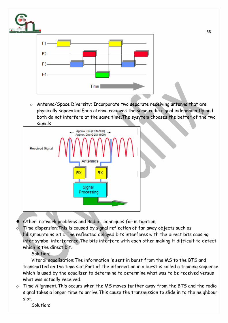
o Antenna/Space Diversity; Incorporate two separate receiving antenna that are physically seperated.Each atenna recieves the same radio rignal independently and both do not interfere at the same time.The sysytem chooses the better of the two signals
Other network problems and Radio Techniques for mitigation;o Time dispersion;This is caused by signal reflection of far away objects such as
hills,mountains e.t.c The reflected delayed bits interferes with the direct bits causing inter symbol interference.The bits interfere with each other making it difficult to detect which is the direct bit. Solution; Viterbi equalization;The information is sent in burst from the MS to the BTS and transmitted on the time slot.Part of the information in a burst is called a training sequencewhich is used by the equalizer to determine to determine what was to be received versus what was actually received.
o Time Alignment;This occurs when the MS moves further away from the BTS and the radio signal takes a longer time to arrive.This cause the transmission to slide in to the neighbourslot. Solution;

39 Timing Advance; When a MS is moving away from the BTS,the timing parameter tells the MS to transmit earlier so that the information on each timeslot stays in sequence.
Radio Network Planning
Radio Network Planning Flow A. Preplanning Stage - Decides the layout of the future network ,It entails; 1. Traffic and Coverage Analysis – the cell planning process starts with this. The analysis produces information about the geographical area and the expected need for capacity. Information collected includes:
Costs of building the network Capacity of the network Coverage and location of network elements Grade of service (max. congestion allowed) Quality of calls Further development of the network
Other information collected are: Population distribution Income distribution in the area Telephone subscription Car usage distribution Subscription charges, call charges
2. Simulation/Nominal Cell Plan – planning of subscriber distribution with the aid of planning software. E.g. ASSET, TCP ,Atoll At this stage, coverage and interference predictions are started. Coverage predictions are made to predict the coverage of the Network to be constructed according to the location and to see if it can meet the subscriber demands. Difficulties encountered in preplanning:
Complex emission environs, severely fluctuating signals
40 Severe Interference Limited frequency resources
B. Planning stage 1. Site surveys – assess the real environment to determine whether the proposed site is a suitable location.
Principles of site selection Population distribution Traffic distribution Subscriber flow direction Surrounding environment Accessibility to site Power supply Signal propagation model
2. Coverage planning – from the coverage predictions made, if the results do not meet the requirements, adjustments need to be made. (a) When there are subscribers outside the cell coverage area where it is not economical to set up a BTS, broadcast stations should be used.
(b) when the signal in the coverage area is weak or if there is a blind area, the micro cell technique is considered to solve this problem.
Micro cells are used in city areas to cover close by areas or distances. (c) If the cell coverage area does not overlap one another enough, consider
increasing the antenna height or the number of BS according to the cell splitting technique.
Cell Splitting - Involves splitting of a large omni-directional cell/BS into smaller cells and splitting of smaller sector cell into smaller cells.
Coverage planning includes selecting the design parameters: Antenna height (Above ground) ,Antenna azimuth angle ,Antenna gain, tilt ,BS height
above sea level ,BS type,Propagation models(Cost 231 HATA model,Okumura HATA model,Cost 231 Wallish Ikegami models e.t.c) and Transmitter output power
3. Capacity Planning – capacity analysis helps to make reasonable investment decisions.
Consider: income, telephone subscription, economic development of the area, population distribution.
Traffic of each subscriber is considered. Traffic is the usage of channels and it is measured in Erlangs.
The traffic a cell can carry depends on the number of traffic channels available and the acceptable probability that the system is congested (GoS) – no. of unsuccessful calls.
To calculate the number of subscriber = Traffic that 1 cell can offer (Acell) / Traffic per subscriber (Asub)

41
4. Radio Parameter Planning ;It involves Handover/cell reselection parameters, Idle mode parameters, MAIO/HSN parameters, cell attribute parameters e.t.c
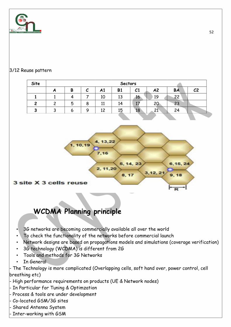
5. Frequency Planning - using radio channels of the same frequency in the cells of differentcoverage areas ,Towns and villages rich in capacity/ subscribers use 4/12 reuse pattern
Big and middle sized cities – 3/9 reuse pattern 6. LAC Planning – the planner presents the allocation and resource application of the
LAC based on network structure and scale 7. Cell Data Making – Configure the relevant data for each BS cell
Cell attribute parameter Cell handover band selection Channel allocation algorism selection If to use frequency hopping, power control or DTX
C. Cutover/Launch - system installation and commissioning and testing are performed following the planning stage.
D. Network Monitoring and Optimization – the system is continually evaluated to determine how well it meets the demand. Frequent optimization and adjustment is needed as subscribers increase.
Link Budget: Used to balance uplink and downlink. Its usually expressed as ; PBTS = PMS + G a –Kb
PBTS= BTS Power

42 PMS = MS Power G a = Antenna Gain Kb = Losses
A link budget is the accounting of all of the gains and losses from the transmitter, through the medium (free space, cable, waveguide, fiber, etc.) to the receiver in a telecommunication system. It accounts for the attenuation of the transmitted signal due to propagation, as well as the anatenna gains , feeder/cable loss and miscellaneous losses. Randomly varying channel gains such as fading are taken into account by adding some margin depending on the anticipated severity of its effects. The amount of margin required can be reduced by the use of mitigating techniques such as antenna diversity and frequency hopping.
A simple link budget equation looks like this: Received Power (dBm) = Transmitted Power (dBm) + Gains ( dB) − Losses (dB) VSWR (Voltage Standing Wave Ratio) VSWR=input/ output. VSWR tolerable value=1.15 Tool for Test/correction: Site Master.
Site Survey Engineering: It involves the process to assess the real environment to determine whether the proposed site is in a suitable location(After nominal cell planning).A nominal coordinate is given for an Engineer to carry out his survey.
We have 2 types of survey namely; Preliminary survey and Detailed survey. In preliminary survey, It is done randomly for a given area. Its the first stage of survey
and the survey must have at least 2 candidates for any point given. Detailed survey comes after deciding on the sites to use, after ITP getting list from
customers, Site Types(Indoor or Outdoor),Site ID, Site Name, Types of antenna and network capacity/site configuration.
Types of sites are New tower(Green field or new location),Roof top(especially in urban areas),Collocation(An existing tower of an operator).
Site Survey involves ; Visiting Target areas(Schools, mosques, hospitals, market e.t.c) Azimuth taken based on target areas,(Antenna type, Antenna height, Structure support,
Antenna model, Antenna quantity, Antenna height on structure with altitude, Antenna tilt, Terrain, population and comprehensive analysis of every other observations. Also Coordinates of search area is needed.
Panoramic view pictures in all direction and Pictures of each candidate Check out for possible obstructions, access roads and other Radio stations Ensure sand, clay or rocky areas are avoided. For roof tops, weak building should be avoided, Confirm enough space for equipment, know
the position of their power supply and earthling system. For collocation sites, ensure there are enough space for your outdoor and indoor units.
The final report can be output to Search area form(SAF),Preliminary site survey

43report(PSSR),Final site survey report(FSSR). Tools required Software incldes Digital Map, MapInfo, Google earth.
Hardware includes Digital Camera for taking pictures Survey GPS for tracing and marking location. It helps in taking coordinates ,your reference
point on earth surface. Compass for getting directions(Antenna orientation/azimuth. Altimeter can give an accurate measurement of altitude. Tape rule for measuring distance Binoculars for viewing environment and microwave link and other far distance objects. Laser meter is used to measure height of buildings, trees and towers. Laptop for easy storage and transfer of information on camera and also battery and
charger is a necessity. Site Configuration; Site configuration is determined by the type of service we want to
render to a particular area. Capacity of a site will determine the nos of TRx to be used on a site(per cell basis). For example;S111/222 configuration means the site has 1 TRx each on 900 band of sector A,B and C,and also 2 TRx each on 1800 band of sector A,B and C.
Practical exercise can be considered in the class on site configurations and Picking points (The Use of Compass, GPS and Digital Camera.)
Radio Base Station or Base Transciever Station
BTS Components ; it consists of BTS indoor and Outdoor Units
Indoor Unit BTS –Base Transceiver Station.
The Base transciever station, or BTS, contains the equipment for transmitting and receiving radio signals (Transcivers),Antennas, and equipment for encrypting and decrypting communications with the Base station controller (BSC).
Typically a BTS has several transceivers (TRXs) which allow it to serve several different frequencies and different sectors of the cell
Components of indoor units Transceiver (TRX) Quite widely referred to as the driver receiver (DRX). DRX are either
in the form of single (sTRU), double (dTRU) or a composite Double Radio Unit (DRU). It basically does transmission and reception of signals. Also does sending and reception of signals to/from higher network entities (like the Base station controller in mobile telephony)
Power amplifier (PA) amplifies the signal from DRX for transmission through antenna; may be integrated with DRX.

44 Combiner Combines feeds from several DRXs so that they could be sent out through a
single antenna. Allows for a reduction in the number of antenna used. Duplexer For separating sending and receiving signals to/from antenna. Does sending and
receiving signals through the same antenna ports (cables to antenna). Baseband receiver unit or RMU(Radio Main unit): This is the unit that performs processing
of traffic received. Outdoor Units are Antenna,Feeder Cable,Jumper cable
,TTA/TMA/RRU(3G),Tower,Aviation light,Lightning arrester e.t.c
Distributed Antenna System

45

46
Link budget Used to balance uplink and downlink. P P +G–K
BTS=MS a b
P = BTS Power BTS
P = MS Power MS
G = Antenna Gain a
K = Losses b
A link budget is the accounting of all of the gains and losses from the transmitter, through the medium (free space, cable, waveguide, fiber, etc.) to the receiver in a telecommunication system. It accounts for the attenuation of the transmitted signal due to propagation, as well asthe antenna gains, feedline and miscellaneous losses. Randomly varying channel gains such as fading are taken into account by adding some margin depending on the anticipated severity of its effects. The amount of margin required can be reduced by the use of mitigating techniquessuch as antenna diversity or frequency hopping.A simple link budget equation looks like this:Received Power (dBm) = Transmitted Power (dBm) + Gains (dB) − Losses (dB)
VSWR (Voltage Standing Wave Ratio)
VSWR=input/ output.
VSWR tolerable value=1.15
Tool for correction: Site Master.

47
Site Installation Workflow Process
TSS means Technical site survey(RF Survey for Green field site or existing one) LOS means Line of site survey for Microwave Transmission RND means Radio Network Design TND Means Transmission Network Design Tx Means transmission RAN Means Radio Access Network

48
Site Installation Steps
Site Installation Procedures(Process):The purpose of the work flow is to enable every Project member recorgnize the stage of the project , how critical it is and also the party involved in the execution.From the above workflow, We will go into the procedures involved in RAN Installation(Ericsson BTS 6301) for the purpose of this class. The installationsteps as to be carried out ON-Site is as listed below;
Antenna//RRU Installation Hoistling of Antennae Main Unit(eNode B) Installation SPD/Power Cabling Cleaning and Installation Checklist Validation(Site Completion checklist)
Antenna/RRU Installation The installation steps as to be carried on Antenna/RRU installation are as listed
below; Dismantling the equipment carton Coupling antenna clamp Attaching the male connector/Antenna jumper Assembling antenna support Fixing antenna to pole

49 Fixing Bracket to RRU Fixing RRU to Pole RRU/Antenna jumper connector Antenna Hoistling
The installation steps as to be carried is as listed below; Mounting Antenna on the tower Running cables and Clamping to tower Cleaning up tower terminations RMU (Node B) Installation
The installation steps as to be carried is as listed below; RMU Slab positioning and Hole drilling Use Plum to check cabinet is leveled Cable termination to RRU/Optical cable termination SPD cabling/Terminating Power cable
After RAN Installation, adequate check must be ensure to enable the installation meets required quality as in the Quality Checklist
Site implementation quality checks Adequate check must be ensure to enable the installation meets required quality;
Check Antenna azimuth,coordinate,tilt,supports. Retrace cable to ensure firm support, good termination Check antenna supports/Boltings Check Optical cable termination Check SPD cabling/Terminating Power cable Cabinet installed according to specifications, leveled & grouting done using insulation
washer & tube and OK. Top Cover, Door and locks are properly installed & working OK. Cable entry kits and sealing installed correctly, Cabinet gaskets not damaged. Air filter installed correctly (and cleaned according to requirements) Internal Plug-in unit / Modules installed correctly as per configuration requirements. Dummy panels & Doors ground straps installed correctly OD Cabinet grouted by using specified size nuts bolts & washers, usage of SS/Galvanized
nuts bolts only. Cabinet is isolated from floor. Check for vertical & horizontal level using sprit level.
eNodeB Cabinet grounded with specified cables and terminated to site main grounding bus bar.
Door Fan sensor installed and working OK ,All nuts bolts properly tightened,All SFP and CPRI cables properly connected,All internal cables properly routed
All Cables are labeled
Refer to Quality Checklist Document for others

50GEOGRAPHICAL NETWORK AREAS
Cell – the smallest radio coverage area of a network and it is supported by one BCCH Location area – the area in which a MS is free to move within without performing a location update. It is also a collection of cells. MSC service area – a collection of location areas PLMN service area – a collection of MSC service areas GSM service area – a collection of all PLMNs in a country
CELL TYPES Omni directional cell – is a cell that contains an omnidirectional antenna installed and broadcasts the same frequency signals in all directions Directional /120 Degree cell – is a cell that has sectoral antennas installed and broadcasts different frequencies. It transmits in only one direction.
FREQUENCY REUSE

51Frequency reuse consists in using the same frequency channel on areas that are separated enough to avoidinterference.
• It is the use of the same frequency pattern in more than one location. • The reason is because the frequency resource of mobile system is very limited. Interference:
distortion of signal resulting in poor signal quality. Types of interference: Co-channel Interference Adjacent channel interference
FREQUENCY REUSE PATTERNS 1(site) x3(sector) = 1/3 2(site) x3(sector) = 2/6 3(site) x3(sector) = 3/9 4(site) x3(sector) = 4/12
7(site) x1(sector) = 7/7 7(site) x3(sector) = 7/21 4/12 Reuse Pattern is the Commonly Used Pattern In GSM Cluster – region in which all the frequencies available to a network are totally utilized.
Distance of reuse between cells
Lower required C/I means shorter distance and higher capacity C/I >= 9dB Reuse separation distance ranges from 4 to 6 times the cell radius
R= Cell Radius D= Frequency reuse distance
Site Sectors A B C A1 B1 C1
1 1 5 9 13 17 21 2 2 6 10 14 18 22 3 3 7 11 15 19 23 4 4 8 12 16 20 24
52
3/12 Reuse pattern
Site Sectors A B C A1 B1 C1 A2 BA C2
1 1 4 7 10 13 16 19 22 2 2 5 8 11 14 17 20 23 3 3 6 9 12 15 18 21 24
WCDMA Planning principle
• 3G networks are becoming commercially available all over the world• To check the functionality of the networks before commercial launch• Network designs are based on propagations models and simulations (coverage verification)• 3G technology (WCDMA) is different from 2G• Tools and methods for 3G Networks • In General
- The Technology is more complicated (Overlapping cells, soft hand over, power control, cell breathing etc)- High performance requirements on products (UE & Network nodes)- In Particular for Tuning & Optimzation- Process & tools are under development- Co-located GSM/3G sites- Shared Antenna System- Inter-working with GSM

53• WCDMA is a wideband direct-sequence code division multiple access system.• User information is spread over a wide bandwidth by multiplying it with quasi-random bits
known as CDMA spreading codes.• Has a chip rate of 3.84Mcps which enables it to support high data rate and increased
multipath diversity.• Support highly variable user data rates which could be understood in the context of
“Bandwidth on Demand” BoD.• Supports soft handoff and Hard handover.• Has unique fast power control at the 15OOHz.
Bearer services
3G main resources are; Code,Power,Channel Element and IuB resource.
Multiple Access technology
Code Resource AllocationIn WCDMA, code resources are mainly divided into channelization codes and scrambling codes.

54 Channelization code:
Channelization codes are based on the orthogonal variable spreading factor (OVSF) technology. Transmission from a single source are separated by channelization codes.
Scrambling code: Scrambling codes are used after spreading, which will not change the signal
bandwidth. They are only used to differentiate different UEs or Node Bs. Premise of code allocation:
ensure not occupied for the code in the root direction and downwards subtree Result of code allocation:
block all low rate SC in subtree and high rate in upwards root direction
In addition to spreading, part of the process in the transmitter is the scrambling operation. This is needed to separate terminals or base stations from each other. Scrambling is used on top of spreading, so it does not change the signal bandwidth but only makes the signals from different
sources separable from each other.
Spreading code = Scrambling code + Channelization code Scrambling codes (Repeat period 10 ms=38400 chips)
– Separates different mobiles (in uplink)– Separates different cells (in downlink)

55– Channelization codes– Separates different channels that are transmitted on the same scrambling code– Orthogonal Variable Spreading Factor (OVSF) codes– Period depends on data rate– User information bits are spread into a number of chips by multiplying them with a
spreading code– The chip rate for the system is 3.84 Mchip/s and the signal is spread in 5 MHz– The Spreading Factor (SF) is the ratio between the chip rate and the symbol – The same code is used for de/spreading the information after it is sent over the
air interfaceChannelization Codes
Channelization Codes have different length depending In the Downlink, Channelization Codes are used to distinguish between data (and control)
channels coming from the same RBS on the bit rate.
In the Uplink, Channelization Codes are used to distinguish between data (and control) channels from the same UE
Scrambling Codes After the Channelization Codes, the data stream is multiplied by a special code to
distinguish between different transmitters. Scrambling codes are not orthogonal so they do not need to be synchronized The separation of scrambling codes is proportional to the code length – longer codes,
better separation (but not 100%) Scrambling codes are 38400 chips long In the Downlink, the Scrambling Codes are used to distinguish each cell (assigned by
operator – SC planning) In the Uplink, the Scrambling Codes are used to distinguish each UE (assigned by network)

56
Scrambling Code planning SC are organized in Code Groups. The first SC in each Code Group differs from the first SC in the subsequent Code
Group by a multiple of 8

57
Multi-path Diversity - the RAKE Receiver

58
•∆T = T2 - T1 > Tchip ⇒ Multi-path diversity
RAKE receiver combines multi-path diversity components
•4 Mcps ⇒ Tchip = 250 ns, corresponding to 75 m distance difference

59
Soft Handover
• Soft handover: A mobile station communicates with two base stations simultaneously.• Soft handover possible because of one-cell reuse • Soft handover necessary because of
one-cell reuse .• Two or more base stations receive the mobile’s signal, which is then combined in the
network
• Soft handover between cells (sectors) at same base station • In uplink, combining can be done in base station’s RAKE instead of in the network
• Less signaling in network • Better combining possible, e.g. maximum ratio combining
Power Control
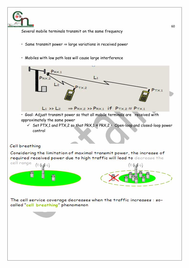
60Several mobile terminals transmit on the same frequency
• Same transmit power ⇒ large variations in received power
• Mobiles with low path loss will cause large interference
• Goal: Adjust transmit power so that all mobile terminals are received with approximately the same power
Set PTX,1 and PTX,2 so that PRX,1 ≈ PRX,2 • Open-loop and closed-loop power control

61
Common RF Terms;
RSCP(Received Signal Code Power); It’s the measurement of Pilot signal level/strength in WCDMA(Unit-dBm)
EcNo or EcIo or Ec/Io or Ec/No(Energy per Chip per Noise spectral density or Energy per Chip per Interference); It’s the measurement of Signal Quality in WCDMA(Unit-dB)
UeTx Power ; It’s the transmit power of the User Equipment ,Its measured in dB(Decibel) CQI(Channel Quality indicator);Its gives measurement about the quality of HSPA channels
during data session. Cell I.D – This is the identity or name given to a particular Node B and its cell by the
operator. UARFCN – It is the frequency band allotted to the operator. One spectrum bandwidth is
of 5MHz in WCDMA or 3G.This window shows us the centre frequency of the bandwidth
62allotted to the operator.
Cell Name – It is the name given to particular Node B’s by the operator generally along the lines of the name of the area the Node B is located in.
Scrambling Code – Scrambling code is a code assigned to a particular cell. There are 512 such codes for the network to differentiate among different Node B’s and these codes can be repetitive. They are of two types primary and secondary.
AS – This stands for Active Set. Active Set is the set of Scrambling Code which the U.E iscurrently latched on and there can be a maximum of 6 Scrambling codes in Active Set.
MN – MN Stands for monitored neighbor i.e the neighbor cell that is detected by the U.E as a neighbor and is also defined as a neighbor in the network. U.E will initiate a Handover onto the monitored neighbor in case the monitored neighbor has a stronger Rx level than the AS.
DN - DN stands for Detected Neighbor and as the name suggests it is the neighbor detected by the UE but, is not defined in our network . Hence, the U.E does not handover to the detected neighbor. It can be because of Overshooting of a site, incomplete neighbor list or in case of a new site. It is very important to optimize and have no DN’s as they are one of the major reasons of Call drops in 3G.
C/I (Carrier to Interference ratio); It must not be less than 12 practically. ARFCN ; Absolute Radio Frequency Channel number, It’s the frequency carrier number in
GSM. It depends on M900 or DCS 1800 Technology. UARFCN ; UMTS Absolute Radio Frequency Channel number, It’s the frequency carrier in
WCDMA. It depends on how many carrier an operator is using. BCCH(Broadcast Control Channel); It’s the Frequency channel that carries system
information and measurement between MS and BTS. MS Camps on this in Idle Mode. Cell ; It’s the coverage area of one BCCH Location Area; Its an area where an MS is allowed to roam without Location update. TCH (Traffic Channel); It’s a channel used when a mobile is in active or dedicated mode, i.e
in conversation. PSC(Primary scrambling Code) ;Its used by UE to differentiate between serving cells in
WCDMA HSDPA(High Speed Downlink Packet Access) ; Download session, Its throughput is greater
than 384 MbPs HSUPA(High Speed Uplink Packet Access) ; Upload session Its throughput is greater than
384 MbPs R99 (Release 99); A technology of WCDMA before HSPA.Its throughput is 384 Kbps
Azimuth/Antenna Orientation; Degree of the direction faced by an antenna. Coordinate; Geographical Location of a site Swapped sector/Cross cabling ;Mismatch of Cable A into B or vise-versa Overshooting; Cell serving outside its server distance Poor Coverage ;Its means poor signal strength Poor Quality/Interference ;It means poor quality No service mode; Emergency calls, no service at all Call set up failure/Blocked call ; A user is unable to make call

63 Dropped Calls; A user call drops during conversation. Handover failure ; A cell attempt to handover to the target cell fails IRAT Handover ; Inter Radio Access Technology Handover(3G to 2G) BSC/RNC ; Base station Controller /Radio Network Controller-Controls BTS or Node Bs BTS/Node B ;Base Transceiver station or Node Bs carries the physical RF equipment like
antennas, cables and the transceivers MS/UE ;Mobile Station/ User Equipment Cell ID/Sector ID ;Name of a particular cell Site ID/Site Name ;Name of a site Road Map ; A vector of the routes in an area. Cell ref/Cell file ; Database of cells or sites-All information enclosed RxLevel;Level of Received signal strength.In dBm or step.If the value inform of step
substract 110 to the value to get dBm value.Rx Level is received power level at MS (maximum Rx Level measured by MS is (±)–60dBm
RxQual;Received signal quality level,measured base on BER (bit error rate).The value is between 0-7,the lower the better.
SQI;The parameter used by TEMS to measure Speech Quality.SQI has been designed to cover all factors that Rx Qual lack to measure. SQI
computationconsiders the factors: the bit error rate(BER),the frame erasure rate(FER),data on
handover events,statistics on the distribution of these parameter. FER – Frame erasure rate; See on“Radio Parameter” windows Hopping ;Indicating if SFH implemented. See on “Current Channel” windows, on hopping
channel, hopping frequencies, MAIO,HSN‟ C/I Interference;The carrier-over-interference. Ratio is The Ratio between the signal
strength of the current ,Serving cell and the signal strength of undesired(interfering) signal components. The C/I measurement function built int oTEMS Investigation enables the identification of frequencies that are exposed to particularly high levels of interference, something which comes in useful in the verification and optimization of frequency plans.
TA Timing Advance.This is valid only in dedicated mode.;To measure the distance of MS from serving cell.. See on “Radio Parameter”windows.
C1 criteria used for cell selection and cell reselection C2 criteria used for cell reselection
o Radio Link Time out; Radio Link Timeout (T100 in the MS) is sent in the Cell Options information element. The mobile uses this value to determine whether there is still good radio contact with the base station. The S counter in the mobile is loaded withthis value, fixed at 8 SACCH frames, and the value is decremented by 1 if an SACCH message could not be decoded, or incremented by 2 if an SACCH message was properly received. If the value drops to 0, the mobile communicates that it has lost the base station.

64
Drive Test OptimizationDRIVE TEST
It is the process of data collection from the network in order to know or have an idea of the subscribers_ perception of the network from the view of a single subscriber. It is carried out to check the network performance by means of coverage evaluation, system availability, network capacity,network retainability and call quality. This is accomplished by checking for the status of the KPI(Key Performance Indicator) such Rx Level (Receive Level), Rx Quality (Receive Quality), SQI (Speech Quality Index), etc in order to make appropriate recommendations where necessary for effective optimization.
DRIVE TEST EQUIPMENT 1 Laptop 2 Dongle 3 TEMS software/Nemo/Xcal 4 Inverter -Power supply needed, usually using inverter in the car from laptop, GPS and MS 5 GPS (Global Positioning System) 6 MS -TEMS phones/Xcal phones 7 USB Hub 8 Scanner, AQM Module for MOS e.t.c
TYPES OF DRIVE TEST Pre-Launch Drive Test or Single Site Verification (SSV) which involves Trx test, Coverage test, Ftp test, PS attach & Detach and Handover test Cluster Drive Test Preswap and post swap Drive test Troubleshooting Drive Test Benchmarking
MODES OF DRIVE TEST 1. Long Call Mode Making continuous call along drive test activity. Before starting the route, call the
drive
test number, ex. 385 for a network. And only stop the call when the route (drive test) is
finished. This is carried out to see the quality and coverage of the network and to check
the network retainability or sustainability e.g Call Drop Rate, Handover Success Rate,
etc
2. IDLE MODE Along the drive test activity, the MS is “ON” but no call occur

65
3. Short Call Mode Creating the sequence of call along the drive test activity Before starting the route
create call sequence, for example:
Create call for 45s and idle for 10 s.
Short call; to check the network accessibility e.g Call Set-up Success Rate
1. RxLevel Level of Received signal strength. In dBm or step. If the value in form of step substract 110 to the value to get dBm value. RxLevel is received power level at MS (maximum RxLevel measured by MS is (±)– 60 dBm

662. RxQual
Received signal quality level, measured base on BER (bit error rate). The value is between 0-7, the lower the better.
3. SQI The parameter used by TEMS to measure Speech Quality.SQI has been designed to cover all factors that RxQual lack to measure.SQI computation considers the factors:the bit error rate (BER),the frame erasure rate (FER)and data on handover events statistics on the distribution of these parameters
4. Others FER -Frame erasure rate; See on “Radio Parameter” windows ARFCN BCCH-BSIC • Absolute Radio Frequency Channel Number of Broadcast Control Channel
• Base Station Identity Code Important data of a site • Hopping • Indicating if SFH implemented. See on “Current Channel” windows, on „hopping channel,
hopping frequencies, MAIO, HSN_ • C/I Interference; The carrier-over-interference ratio is the ratio between the signal strength
of the current serving cell and the signal strength of undesired (interfering) signal components. The C/I measurement function built into TEMS Investigation enables the identification of frequencies that are exposed to particularly high levels of interference, something which comes in useful in the verification and optimization of frequency plans.
• TA Timing Advance. This is valid only in dedicated mode. ; To measure the distance of MS from serving cell.. See on “Radio Parameter” windows.
• C1 • criteria used for cell selection and cell reselection • C2 criteria used for cell reselection
Starting off on TEMS for Drive Test Launch TEMS on your system (Desktop or Laptop) Open new workspace on TEMS Investigation: Data Collection The view is as below

67
To open the necessary windows needed for Data Collection; Click on Presentation>> GSM>> the following five windows:
• Current Channel
• Hopping channel
• Radio parameters
• Serving + Neighbor
• GSM line chart
• Map
These six windows are opened up for Drive testing
Arrange them to fit into screen
To connect equipments Insert the following into the available USB ports on the system or if there are limited ports, make use of a USB hub having multiple ports
DongleMS1MS2GPSTo open the map, click on presentation>> positioning>> map

68
To Load cell file Click on “Configuration” on the main tool bar>> General Small window tab “General” pops up on screen
Double click on “cellfile Load”. Window named “Properties” pops up
Click on “Add” -“Open cell name file” window pops up. Select location where cellfile is save on

69the systemDouble click on the cell file to load
Click on “ok”What you will have is a map with cluster spots as shown below
Click on “Zoom in” to expand cluster circled in red by dragging the “zoom in” icon to the the cluster and expanding as shown by the instructor.
To input Cell Label Click on “theme setting” on tool bar,Drop down cell layer>> double click on “Cell Theme 14”Shows “Edit theme cell theme 14” window>> check “cell label box”

70
Click “ok”>> close,Labels appear on each site as shown below.
To load route maps
Click on “Layer” control icon on map windowClick on “Add”Select Location where route map is saved on the system (Laptop/desktop)Highlight all required routes e.g. • Secondary road , Major road, Main road and Highway • Click on “open” Routes are loaded on TEMS
Setting the command sequence Click on control on menu bar>> command sequence Command sequence window pops up>>Edit Drop down on “Voice/Video” (depending on the test being carried out)>> Dial To initiate call Click “connect all” on menu bar of TEMS window

71
3G Workspace
2G Workspace

72

73
• During TuningNo traffic in the network, No subscribersNetwork tuned only based on drive test dataLabour intensive with repeated drive testAll is about Pre-launch activities
• During OptimizationCommercial traffic, subscribers using the networkStatistics used widely to monitor network performanceDrive testing just in caseAll is about Post–launch activities
Things to look out for in Drive Test• Voice /Video/PS calls
– Long calls– short calls
• Identify problem areas– Blocked calls– Dropped calls– Delay/Throughput– Call set-up failure and drops during short calls can be mainly– used to analysis Accessibility failure due to: – UE Failure– Unsuitable Parameters Setting– Coverage Problem
74– Interference– Others – Drops during long call can be used to identify:– Missing Neighbor Relation– Coverage Problem– UE Problems– Network Characteristics– Best Parameter Setting– Others
KEY PERFORMANCE INDICATORS – Accessability (Call set-up success rate)– Retainability (Dropped calls)– Mobility (Handover success rate)– Integrity (BLER and throughput)
LTE DRIVE TEST PARAMETERS
RSRP :- Reference signal receive power. RSRP (dBm) = RSSI (dBm) -10*log (12*N)
where RSSI = Received Signal Strength Indicator N: number of RBs across the RSSI is measured and depends on the BW
Significance : RSRP is the most basic of the UE physical layer measurements and is the linear average power (in watts) of the downlink reference signals (RS) across the channel bandwidth for the Resource elements that carry cell specific Reference Signals.
Knowledge of absolute RSRP provides the UE with essential information about the strength of cells from which path loss can be calculated and used in the algorithms for determining the optimum power settings for operating the network. Reference signal receive power is used both in idle and connected statesRange :- -44 to -140 dBm
RSRP term is used for coverage same as RSCP in 3G
RSRQ :Reference signal receive quality
RSRQ = RSRP / (RSSI / N)
N is the number of resource blocks over which the RSSI is measured
RSSI is wide band power, including intra cell power, interference and noise.

75
Significance :- It provides the Indication of Signal Quality . Measuring RSRQ becomes particularly important near the cell edge when decisions need to be made, regardless of absolute RSRP, to perform a handover to the next cell. Reference signal receive quality is used only during connected states
Range :- -3 to -19.5 dBRSRQ term is used for Quality same as Ec/No in 3G.SINR :- Signal to Noise Ratio.SINR = S / I + NS -- Average Received Signal PowerI -- Average Interference powerN -- Noise Power
Significance : Is a way to measure the Quality of LTE Wireless Connections. As the energy of signal fades with distance i.e Path Loss due to environmental parameters ( e.g. background noise , interfering strength of other simultaneous transmission)
RSSI :- Received Signal Strength Indicator.RSSI = wideband power = noise + serving cell power + interference powerRSSI=12*N*RSRPRSSI per resource block is measured over 12 resource elements.
N: number of RBs across the RSSI is measured and depends on the BW Based on the above:
RSRP (dBm) = RSSI (dBm) -10*log (12*N)
• Significance :– Is the parameter represents the entire received power including the wanted power from the serving cell as well as all the co channel power & other sources of noise
• CQI :- Channel Quality Indicator Range :- 1 to 15
Significance: CQI is a measurement of the communication quality of wireless channels i.e. it indicates the downlink mobile radio channel quality as experienced by the UE .CQI can be a value representing a measure of channel quality for a given channel. Typically, a high value CQI is indicative of a channel with high quality and vice versa.
• CQI is measured in the Dedicated mode only.•
• CQI depends on the RF conditions.•
• Better the CQI better the throughput will get and vice versa.

76• PCI :- Physical Cell Id
Range :- 0 to 503• Significance - PCI used to identify the cell & is used to transmit the data• PCI = PSS + 3*SSS
PSS is Primary Synchronization Signal ( Identifies Cell Id ). PSS value can be 0, 1 & 2 SSS is Secondary Synchronization Signal ( identifies Cell Id group). SSS value can be 0 to 167.
• BLER :- Block Error Rate• Block Error Ratio is defined as the ratio of the number of erroneous blocks
received to the total number of blocks transmitted Significance -
A simple method by which a UE can choose an appropriate CQI value could be based on a setof Block Error Rate (BLER) thresholds . The UE would report the CQI value corresponding to theModulation Coding Schemes that ensures BLER ≤ 10% based on the measured received signal quality
• BLER is Calculated using Cyclic Redundancy error Checking method High BLER leads to loss of Peak rates & efficiency
BLER threshold should be low i.e. ≤ 10%
Downlink Throughput -I n E-UTRAN may use a maximum of 2 Tx antennas at the ENodeB and 2 Rx antennas at the UE ( MIMO ). Significance - Target for averaged user throughput per MHz, 3 to 4 times Release 6 HSDPA i.e Higher user throughput as compared to 3G ( Over 300 Mbps downlink as
compared to 14 Mbps in UMTS) - The supported user throughput should scale with the spectrum bandwidth.
Uplink Throughput -I n E-UTRAN uses a maximum of a single Tx antenna at the UE and 2 Rx antennas at the E Node B. - Greater user throughput should be achievable using multiple Tx antennas at the UE ( MIMO - Significance-
Target for averaged user throughput per MHz, 2 to 3 times Release 6 Enhanced Uplink i.e Higher user throughput as compared to 3G (Over 50 Mbps Uplink as compared to 5.76 Mbps in UMTS).The user throughput should scale with the spectrum bandwidth provided that the maximum transmit power is also scaled.

77
Thank You!
Instructor;Ogundele Adeola