matamata-piako district council development manual · matamata-piako district council development...
TRANSCRIPT

Matamata-Piako District Council
Development Manual 2010

Matamata-Piako District Council Development Manual 2010
Version : October 2015 Contents Page 1

Matamata-Piako District Council Development Manual 2010
Version : October 2015 Contents Page 2
Contents
Part 1 General Information
1.0 Background 1.1 Introduction to the Manual 1.2 MPDC Infrastructure Code of Practice 1.3 Parties Involved 1.4 Development Manual Control 1.5 Interpretation and Abbreviations 1.6 Alternative Solutions
Part 2 Earthworks and Stability
2.0 Background 2.1 Variations: Earthworks 2.2 Standards 2.3 Scope 2.4 General 2.5 Technical Responsibilities 2.6 Planning and Design
Part 3 Road Works
3.0 Introduction 3.1 Variations: Road Works 3.2 Definitions 3.3 Road Classifications 3.4 Philosophy for Road Network Design 3.5 Parking 3.6 Road, Carriageway and Formation Widths 3.7 Road Geometry 3.8 Road Pavement 3.9 Road Drainage 3.10 Footpaths 3.11 Cycle Traffic 3.12 Vehicle Crossings 3.13 Berms 3.14 Road Lighting 3.15 Signs and Roadmarking 3.16 Service Lanes 3.17 Privateways 3.18 Parking Bays 3.19 Features and Berm Furniture 3.20 Pedestrian Accessways 3.21 Road Design Quality Assurance 3.22 Verandahs 3.23 Stock Crossings 3.24 Road–Rail Intersections
Drawings

Matamata-Piako District Council Development Manual 2010
Version : October 2015 Contents Page 3
Part 4 Stormwater Drainage
4.0 Introduction 4.1 General 4.2 MPDC Stormwater Management Bylaw 4.3 Variations: Stormwater Drainage 4.4 Definitions 4.5 Useful Documents and Standards 4.6 Stormwater System 4.7 Resource Consents Required 4.8 Design Requirements 4.9 Open Water Courses 4.10 The Hydraulic Design of Pipelines 4.11 Location of Pipelines 4.12 Pipes 4.13 Joints 4.14 Minimum Cover Over Pipes 4.15 Manholes 4.16 Connections 4.17 Ramped Risers 4.18 Connections to Deep Lines 4.19 Inlet and Outlet Structures 4.20 Catch pits and Catch pit Outlet-Pipes 4.21 Stormwater Soakholes 4.22 Subsoil Drainage 4.23 Planted Stormwater Devices
Part 5 Wastewater Drainage
5.0 Introduction 5.1 Variations – Wastewater Drainage 5.2 General 5.3 Calculation of Flows 5.4 Location of Pipelines 5.5 Pipes 5.6 Pipeline Minimum Grade Guideline 5.7 Joints 5.8 Structural Strength of Pipes and Bedding 5.9 Pipeline Construction 5.10 Minimum Cover Points 5.11 Manholes 5.12 Connections 5.13 Requirements for Service Pipe Size and Alignment 5.14 Ramped Risers 5.15 Connection to Trunk and Interceptor Pipelines 5.16 Connections to Deep Lines 5.17 Testing 5.18 Pumping Stations 5.19 Rising Mains

Matamata-Piako District Council Development Manual 2010
Version : October 2015 Contents Page 4
5.20 Commissioning Test – Pump Stations Drawings
Part 6 Water Supply
6.0 Introduction 6.1 Variations – Water Supply 6.2 General 6.3 Useful Documents and Standards 6.4 Design Requirements 6.5 Reticulation 6.6 Alignment of Water Mains in Street 6.7 Intersections 6.8 Rider Mains 6.9 Hydrants 6.10 Valves 6.11 Depth of Water Mains 6.12 Anchor or Thrust Blocks 6.13 Connections to Private Property
Drawings
Part 7 Street Landscaping
7.0 Introduction 7.1 Minimum Requirements 7.2 Means of Compliance 7.3 Standard and Non-Standard Options for Street Tree Location
Drawings
Part 8 Network Utilities
8.0 General 8.1 Conversion to Underground on Existing Streets 8.2 Industrial and Commercial Subdivisions 8.3 Location of Services 8.4 Waterway Crossings
Part 9 Landscaping Engineered Stormwater Devices
9.0 Introduction 9.1 Minimum Requirements 9.2 Means of Compliance 9.3 Planting 9.4 Plant Sourcing 9.5 Mulching 9.6 Useful Documents and Standards

Matamata-Piako District Council Development Manual 2010
Version : October 2015 Contents Page 5

Matamata-Piako District Council Development Manual 2010
Version: October 2015 Part 1 – General Page 1-1
Part 1 – General Information
1.0 Background It has been determined that the 2005 amendment to the Resource Management Act 1991 requires that the Development Manual be integrated into the District Plan in order to be enforceable. Matamata-Piako District Council (“MPDC” or the “Council”) has resolved that the MPDC Development Manual should become part of the District Plan, as the “preferred means of compliance”.
1.1 Introduction to the Manual The MPDC Development Manual sets out the processes and standards that are expected to be followed and met whenever any development project is undertaken in accordance with Matamata-Piako District Plan. The MPDC Development Manual recognises that Council and other network operators will become the owners of the infrastructure created in the subdivision or development process. Council and other network operators will assume responsibility for ongoing maintenance of these systems. To that end it is important that there is confidence that the systems are designed and constructed in a manner that ensures that they are fit for purpose at the time of transfer of ownership. The performance standards and rules for subdivision and developments are set out in the Matamata-Piako District Plan. The MPDC Development Manual represents the “preferred means of compliance” with the District Plan requirements. The Development Manual is not the only method that may be adopted to comply with the requirements of the District Plan. The Developer may produce an alternative design, however in that case must clearly demonstrate that the design meets the relevant District Plan requirements. The Development Manual also applies in the case of any renewal or improvement works that are to be carried out by or for Council. They are to be used for any design that is carried out for Council either internally or by an external design consultant. While it is acknowledged that there are objectives stated within the following section, all subdivision and development proposals will be considered against the provisions in Section 5.9 of the District Plan. The objectives stated within the MPDC Development Manual provide additional guidelines.
1.2 MPDC Infrastructure Code of Practice
The Development Manual is supplemented by MPDC’s Infrastructure Code of Practice. The relationship between the two documents can be described as follows:
• The purpose of the development Manual is to guide engineering design, whereas:
• The MPDC Infrastructure Code of Practice sets out the process, technical specifications and quality systems that apply to all infrastructure services within the District. It contains the standards for materials and construction that are required by MPDC and applies to all infrastructure works whether by way of direct contract to Council, or where the infrastructure assets will become part of the Council network, or will be vested in Council, following completion.

Matamata-Piako District Council Development Manual 2010
Version: October 2015 Part 1 – General Page 1-2
As such, the two documents are cross-referenced, and should be considered jointly. The Development Manual is incorporated into the District Plan and is an RMA document. The Infrastructure Code of Practice, on the other hand, is adopted through the Local Government Act process and will be amended and adopted as changes are identified on an ongoing basis.
1.3 Parties Involved An approval for subdivision is effectively an agreement between Council (as Territorial Local Authority) and the Developer as the owner of the land being subdivided or developed. Under this “agreement”, the Developer designs and constructs infrastructure services which become assets of the Council and network operators when completed. For its part, Council will issue the certificate(s) that are required before “Titles” will be issued for the separate lots that are created in a subdivision or sign off completion of a development, thus allowing the Developer to sell Title to those lots or to exercise the objectives of the development. The two key parties involved are: • Matamata-Piako District Council referred to as the “Council”. • The person who applies for approval for a subdivision or development,
referred to as the “Developer”. Each party may have associated parties as follows: Council may have associated parties including: • Network operators, e.g. Telecom New Zealand, Powerco Ltd. • Specialist technical advisers.
The Developer may have associated parties including: • Developer’s Representative. • Person engaged by the Developer to undertake the role of “Engineer”,
responsible for certifying the quality and compliance of the development works.
• Specialist technical advisers such as planning, design, engineering and survey consultants.
• Contractor (or Contractors) who carry out the construction works.
The Development Manual also applies to new, renewal or improvement works to be undertaken by Council.
1.4 Development Manual Control The MPDC Development Manual (2010) is controlled as part of the Council’s District Plan. It can only be modified through a Plan Change process.
1.4.1 Suggesting Improvements Any user of the Manual has the ability to submit an “Opportunity for Improvement” form (OFI) to Council where they feel that there is something in the Manual that could be improved.

Matamata-Piako District Council Development Manual 2010
Version: October 2015 Part 1 – General Page 1-3
1.5 Interpretations and Abbreviations
1.5.1 Interpretation In this Manual, unless inconsistent with the context, the following shall apply. Should a definition be in conflict with the definitions in the District Plan, then the District Plan shall prevail. Contractor Means the company engaged to undertake the physical
works. • In the case of land development, the Contractor shall be
responsible to the Developer. • In the case of works constructed by the Council, the
Contractor’s responsibility shall be as defined by the General Conditions of Contract for the works.
Council Means Matamata-Piako District Council, or an authorised
representative of the Matamata-Piako District Council.
Developer means the company or person who is applying for or who holds consent for the land being subdivided or developed.
Developer’s Representative
means the person or persons appointed by the Developer to represent them.
Engineer has a different meaning depending on the party relationships involved in the works: • Where the work is being carried out as part of a
subdivision or development, Engineer means a person who is commonly entitled to practice as a Chartered Professional Engineer/Registered Surveyor and has experience in utilities engineering acceptable to Council and who is engaged by the Developer to certify the quality and compliance of development works.
• Where the work is being carried out as a direct contract to Council, then Engineer has the meaning as set out in NZS 3910:2003 – Conditions of Contract for Building and Civil Engineering Construction.
Geotechnical Engineer
Means a person who has professional experience in soils engineering and carries Professional Indemnity Insurance cover.
Household Unit Means any building or group of buildings, or part thereof, used or intended to be used principally for residential purposes and occupied or intended to be occupied by not more than one household.
Means of Compliance
means a method by which the requirements of the District Plan may be complied with. It implies that there may be other methods which may meet the requirement, but which may be subject to specific consideration or approval.

Matamata-Piako District Council Development Manual 2010
Version: October 2015 Part 1 – General Page 1-4
Owner means the owner of the land being subdivided or developed.
The Works The works shall generally be defined as the works for which this specification is being used and shall have the definition of “Contract Works” as defined in NZS 3910:2003.
NZ Transport Agency
New Zealand Transport Agency.
1.5.2 Abbreviations DC (Document Controller)
is the District Planner of the Council.
DMM (Development Manual Manager)
is the Asset Manager – Strategy and Policy Department of the Council.
MPDC means the relevant authorised officer of the Council.
LESD means Landscaping of Engineered Stormwater Devices.
PGU or RPD means the Regulatory Planning Department of the Council.
NZ Transport Agency
means the New Zealand Transport Agency.
WEL means the relevant electricity network provider.
WHAP Means crushed general aggregate (WHAP) intended for use as sub-base material or shaping for stabilisation purposes (see Code of Practice).
1.6 Alternative Solutions
1.6.1 Procedure The MPDC Development Manual is a means of compliance to meet the provisions in section 5.9 of the District Plan. A developer may wish to depart from the preferred solution as set out in the MPDC Development Manual. The alternative details or specifications need to be raised with the Council as early as possible in the design process to ensure a collaborative solution can be reached before the resource consent application is made and before detailed construction plans have to be submitted for approval. This will involve submitting to Council a scoping report and Specification Variation Request form/s which will detail the proposed variation or alternative and identify how the alternative solution meets the design criteria. Council staff will consider any variation application and provide a response confirming, rejecting or requesting further information or clarification of aspects.

Matamata-Piako District Council Development Manual 2010
Version: October 2015 Part 1 – General Page 1-5
Provided the pre-application process has been successful, all variations from the MPDC Development Manual will be known by the Council, and approval should be a formality. Ultimately the discretion to accept the variation lies with the Council, under delegated authority. Council expects consultation at the earliest possible stage where alternative engineering solutions are to be sought. The process shall be undertaken without undue delay.
To best achieve these outcomes, the process leading to approval of a development must be collaborative. At the very least it must involve the developer, their professional advisers, Council Planning Staff and Engineering Staff. The Specific Variation Request form is attached at the end of this section. The following flow chart illustrates the process to be followed when preparing and submitting a development proposal:

Matamata-Piako District Council Development Manual 2010
Version: October 2015 Part 1 – General Page 1-6
Project Conceived
MPDC District Plan considered
NZ Urban Protocol
Crime Prevention through Environmental Design
(CPTED)
MPDC Design Guidelines
Concept meeting with MPDC planning and engineering staff (for complex and large scale
projects)
Prepare brief scoping report on proposal detailing any variations of the Development Manual 2010
Submit proposal, scoping report and Specification Variation
Request form to MPDC for review
Meet with MPDC staff as required to
discuss proposal
Written response from MPDC
Update proposal
Resource Consent application made including urban design statement and indication of
compliance with Development Manual
MPDC processes application
Resource Consent decision (subject to final approval of
engineering plans)
If approved, prepare and submit to MPDC detailed engineering plans for approval based on consented development proposal.
Detailed design documents assessed by MPDC planning and
engineering staff
Approval by MPDC planning and engineering staff
Commence Project Construction

Matamata-Piako District Council Development Manual 2010
Version: October 2015 Part 1 – General Page 1-7
1.6.2 Design Criteria A developer may depart from any aspect of the MPDC Development Manual, however any departure and the suggested alternative will be assessed against the following design criteria: 1. The provisions in section 5.9 of the Matamata-Piako District Plan. 2. The following overriding factors:
a) The desire to achieve the “Seven Cs” of the New Zealand Urban Design Protocol.
b) Safe and functional outcomes. c) Sustainability of alternatives. d) Economics of long term maintenance.
3. The criteria tables below. The following tables identify specific aspects of design relating to each section of the MPDC Development Manual. These aspects are some of the key criteria that will be considered when assessing an application for departure from the standards. It must be noted that these may not be the only criteria, by which an assessment is made, however these give some guidance as to the expectations of Council when accepting a variation. Only those departures from the MPDC Development Manual applied for and approved through the “Specific Variation Request Form” (included herein) shall be permitted.
Part 2: Earthworks and Land Stability
Element Factor Comment
Earthworks Design Standards for Earthworks
Minimum standards shall be met.
Part 3: Roading
Element Factor Comment
Parking Adequate Saturation Sufficient parking shall be provided to cater for a likely need given the neighbourhood environment, housing density, street function and future developments.
Carriageway Width
Street Function / Status / Traffic Volumes
Allowances shall be made to cater for emergency service vehicles. Functional priorities shall be provided for.
Safety of Cyclists and Pedestrians
The needs of the vulnerable road user shall be considered and incorporated into the development.
Traffic Safety All classes of vehicle shall use the carriageway in a safe manner without causing any measurable safety concerns.
Speed Environment The speed environment shall be appropriate to the function of the road, the type of surrounding development

Matamata-Piako District Council Development Manual 2010
Version: October 2015 Part 1 – General Page 1-8
and width of carriageway. Connectivity Roads connecting to the existing
network shall have a function and purpose consistent with that network and with future development.
Horizontal and Vertical Geometry
Safety for all road users shall be the priority and this shall be incorporated into the horizontal and vertical geometry.
Character Roads shall have an appropriate character that is consistent with the surrounding neighbourhood.
Intersection Spacing
Intersection Treatment Close offset intersection spacing may be acceptable if there is appropriate treatment of the intersection consistent with the likely traffic volumes.
Context Low speed environments can support less conventional intersections
Intersection Radii Context These shall be designed so that they cater for both pedestrian and vehicle movements.
Safety Radii on all intersections shall be designed so that they allow for vehicle and pedestrian movements in a safe and consistent manner.
Access Radii on roads leading to a business / industrial area shall be designed to cater for heavy commercial vehicle movements.
Sight Distances No Variation Permitted through the Development Manual variation process.
Adequate sight distances shall be provided in all situations.
Longitudinal Gradients (Increased)
Length of Grade The steepness shall not be increased so that it causes adverse safety, drainage, visibility alignment or future maintenance issues.
Location The location of sudden grade changes shall be located away from intersections and curves (including sag and crest)
Character Function and safety shall be maintained where the existing landscape or terrain is altered.
Road Pavement Construction and Testing
No Variation Permitted The pavement shall be designed to cater for likely traffic in the development, including heavy vehicles e.g. rubbish trucks
Road Drainage
Longevity, Reliability and Maintenance Requirements
Alternative stormwater systems can often require a greater level of servicing and cost to maintain them. Any alternative proposals shall identify the servicing requirements and all whole of life maintenance / capital costs.
Impact on Formal Reticulation
Any impacts on the downstream reticulation shall be identified and addressed, including positive ones to attenuate the flow.

Matamata-Piako District Council Development Manual 2010
Version: October 2015 Part 1 – General Page 1-9
Road Safety and Secondary Flowpaths
If the failure of the alternative system results in widespread ponding, this will impact on road safety. Secondary flow paths shall be designed to cater for the entire run-off, in the event of a system failure.
Local Subsoil Effects Subsoil drain discharge points shall be located away from the pavement, hillsides and embankments so that pavement saturation / or slope instability does not occur.
Footpaths Context Footpaths shall be provided to access public open spaces in a planned and logical manner, and shall meet present and future needs across the development.
Pram Crossings Safety / Desire Lines All pram crossings shall be located in a safe location that provides the user with the best visibility of approaching traffic.
Road Lighting Luminance – No Variation Permitted
Adequate lighting shall be provided throughout the development so that it is safe for all night-time users of footpaths and streets.
Road Markings Environment In some special cases a reduction in road markings may be appropriate, but only where other supporting treatments are present and safety is not comprised.
Street Furniture Context The provision of street furniture for seating, cycle racks, rubbish bins etc often enhances the built environment.
Character The inclusion of appropriate street features and public art can strengthen and enhance the development, neighbourhood and wider community.
Creativity The creation of a quality place to live and/or work is often related to the creativity of the space. Appropriate street furniture and its placement can aid in achieving this outcome.
Safety All street furniture shall be durable, safe and appropriately positioned so that it enhances the safety of the space.
Maintenance Durable street furniture shall be used that is easy and cost effective to maintain and renew.

Matamata-Piako District Council Development Manual 2010
Version: October 2015 Part 1 – General Page 1-10
Part 4: Stormwater Drainage
Element Factor Comment Location Access Accessing the pipeline for
maintenance and connections Disruption / Traffic Delay Locating the pipeline in the berm may
minimise the need for highly restrictive traffic management required during maintenance. This is important in both narrow carriageways and very busy roads.
Protection of Costly Surfacing
Within town centres or business areas, where special surface coatings may be used, locating pipelines in the berm may reduce the need to uplift and relay expensive paving materials.
Manhole Lids Availability / Cost The use of alternative lids, to match the surrounding paving can add to the character of a place, however the cost and availability of replacement lids must be considered.
Catch pits Efficiency A standard catch pit in an ideal installation has an entry capacity of 20–25 L/s. Any alternative must be shown to have at least this capacity.
Effective Screening The screening effectiveness of any alternative grating must be equivalent to a standard catch pit grating.
Cost The cost and ease of replacing the unit or components will be considered.
Part 5: Wastewater Drainage
Element Factor Comment Location Access Accessing the pipeline for
maintenance and connections Disruption / Traffic Delay Locating the pipeline in the berm may
minimise the need for highly restrictive traffic management during maintenance. This is important in both narrow carriageways and very busy roads.
Protection of Costly Surfacing
Within town centres or business areas, where special surface coatings may be used, locating pipelines in the berm may reduce the need to uplift expensive paving materials.
Manhole Lids Availability / Cost The use of alternative lids to match the surrounding paving can add to the character of a place. However the cost and availability of replacement lids must be considered.

Matamata-Piako District Council Development Manual 2010
Version: October 2015 Part 1 – General Page 1-11
Part 6: Water Supply
Element Factor Comment Reticulation Layout
Level of Service Applicant must show that all proposed and potential users can be serviced to the level of service required, including connectivity to provide through mains where available.
Alignment Access Sufficient access must be available for maintenance and future connections to the network.
Road Widening If road widening could be possible in the foreseeable future then the location of the main could be a consideration to this future work.

Matamata-Piako District Council Development Manual 2010
Version: October 2015 Part 1 – General Page 1-12
Specification Variation Request This form must be submitted where the applicant proposes to depart from the requirements of the Development Manual Application details Name of applicant:
Project name:
Project location:
Project description:
Resource consent number: Date:
Variation details Proposed variation to standard:
Section numbers in Development Manual affected:
Section No. Current standard Proposed standard
Reason for variation:
Sketch of alternative (if applicable):

Matamata-Piako District Council Development Manual 2010
Version: October 2015 Part 1 – General Page 1-13
Office use only Reviewing officer:
Position:
Decision: Approved Declined
Reason for decision:
Conditions:
Issued by: Position:
Signed: Date:

Matamata-Piako District Council Development Manual 2010
Version: October 2015 Part 1 – General Page 1-14

Matamata-Piako District Council Development Manual 2010
Version: October 2015 Part 2 – Earthworks and Stability Page 2-1
Part 2 – Earthworks and Land Stability
2.0 Background This section of the Manual sets out the basic design requirements for earthworks that are to be carried out as part of the subdivision or development. Some construction information is included for completeness. Note: Detailed information on construction standards are included in the MPDC Infrastructure Code of Practice.
2.1 Variations: Earthworks No variations from the Development Manual will be permitted in respect of earthworks.
2.2 Standards Any person who is involved in the design of earthworks for a development should be familiar with the following NZ Standards: NZS 4402:1986 – Methods of Testing Soils for Civil Engineering Purposes NZS 4431:1989 – Code of Practice for Earth Fill for Residential Development Note: Developers should also be familiar with the requirements of the Waikato Regional Council Guidelines – “Erosion and Sediment Control for Soil Disturbance Activities”.
2.3 Scope This part of the Manual sets out the requirements for the design of earthworks or preparation for foundations, or both, including: • The excavation and filling of land to form new contours. • The assessment and protection of slope stability. • The suitability of both natural and filled ground for the founding of roads,
buildings, services and other works. Because of the wide range of soil types, physical conditions and environmental factors applying in different areas of the district, it is not possible to lay down precise requirements which will be applicable in all cases.
2.4 General Earthmoving activities are subject to both Regional and District Council approvals. Resource consents, if required, shall be obtained before commencement of site work. Choice of final landform is dependent on many factors which may be specific to the development or subdivision. These include: • Relation with surrounding landscape. • Size. • Roading pattern. • Preservation of natural features. • Stability.

Matamata-Piako District Council Development Manual 2010
Version: October 2015 Part 2 – Earthworks and Stability Page 2-2
• Damage by flood or other natural occurrences such as erosion by sea, river, or surface water run-off.
The intent is that every lot shall contain a safe building platform suitable for the erection of building types appropriate to the zoning of the land. All resource consent applications for subdivision, or any other type of development where land stability needs to be addressed shall be accompanied by a Statement of Suitability for Development relevant to the site. Council may request that a more detailed geotechnical report be undertaken to prove the suitability of the site for its intended purpose after evaluating the engineer’s statement.
2.5 Technical Responsibilities Where any urban land subdivision or development involves carrying out bulk earthworks, or the assessment of slope stability, or the detailed evaluation of the suitability of natural ground for the foundations of buildings, streets, services or other works, then a geotechnical engineer shall be appointed by the developer to carry out the following functions: a) Prior to detailed planning of any development, to undertake a site inspection
and such investigations of subsurface conditions as may be required. b) To review the drawings and specifications defining the earthworks proposed,
and submit a written report to the Council on foundation and stability aspects and any proposed departures from this Manual and associated standards.
2.5.1 Preliminary Site Evaluation Prior to any detailed planning or design, the Developer or geotechnical engineer, as applicable, shall undertake a preliminary evaluation of the general nature and character of the site in sufficient detail to determine the likely requirements for earthworks or the need for further investigations into the suitability of foundation conditions, or both, and the stability of the natural ground. The preliminary evaluations should be carried out in the context of the total surroundings of the site. In simple cases a visual appraisal may be sufficient. In other cases, depending on the nature of the project, its locality, the scale of development proposed and individual site characteristics, particular attention may need to be given to the following matters, which should normally be considered prior to preparing a scheme of subdivision or development.
a) Drainage It is important to identify the existing natural drainage pattern of any area and to locate natural springs or seepage. Where any natural drainage paths are to be interfered with or altered by earthworks, appropriate measures should be taken to ensure that sufficient adequate alternative drainage facilities are provided.
b) Slope Stability Some natural slopes exist in a state of marginal stability and relatively minor works such as trenching, excavation for streets or building platforms, removal of scrub and vegetation, or the erection of buildings, can lead to failure. Signs of instability include cracked or hummocky surfaces, crescent shaped depressions, crooked fences, trees or power poles leaning uphill or downhill,

Matamata-Piako District Council Development Manual 2010
Version: October 2015 Part 2 – Earthworks and Stability Page 2-3
uneven surfaces, swamps or wet ground in elevated positions, plants such as rushes growing on a slope or water seeping from the ground.
c) Foundation Stability A study of the general topography of the site and its surroundings may indicate areas which have previously been built up as a result of natural ground movement or by the deliberate placing of fill material. Unless such fill has been placed and compacted under proper control, long-term differential settlement could occur causing damage to superimposed structures, roads, services or other subdivision works.
2.5.2 Specialists Services Where a soils report is required, then prior to or at the time of applying for a subdivision or development consent, the developer shall submit to Council a written report from a geotechnical engineer setting out the particulars of any investigations carried out. The report should include details of contours, natural features and modifications proposed thereto, and include a statement from the geotechnical engineer as to the suitability of the land for subdivision or development, with details of any special conditions that should be imposed. Note: A suitable format for this statement of opinion is included within the MPDC Infrastructure Code of Practice.
2.6 Planning and Design
2.6.1 Landform The final choice of landform should represent the most desirable compromise between taking account of the factors referred to in Section 2.6 and the preservation of natural features and the natural quality of the landscape including the retention of natural watercourses. The choice of a suitable landform is dependent on many factors which may be specific to a particular site. In general unnecessary earthworks should be avoided but considerations which may justify the carrying out of earthworks include: a) Minimising the possibility of damage to property occurring through ground
movement in the form of slips, subsidence, creep, erosion or settlement. b) Minimising the possibility of damage to property occurring through flooding, or
surface water run-off. c) The development of a more desirable roading pattern with improved
accessibility to and within the site and the creation of a better sense of orientation and identity for the area as a whole.
d) Efficient overall land utilisation including the quality of individual sites and amenity areas around buildings, the economics of providing engineering services, and the standard of roading and on-site vehicular access.
e) The need to create suitably graded areas for playing fields and other community facilities.
f) The enhancement of the general environmental character of the area by softening the landscape or by artificially creating or emphasising landforms of visual significance, particularly on flat sites or on areas devoid of landscape features.
g) The safety of the site by incorporating CPTED (Crime Prevention through Environmental Design) principles.

Matamata-Piako District Council Development Manual 2010
Version: October 2015 Part 2 – Earthworks and Stability Page 2-4
2.6.2 Soils and Investigations Where appropriate the general nature and shape of the ground should be studied and particular note taken of: a) The geological nature and distribution of soils. b) Existing and proposed drainage conditions and the likely effects on ground
water. c) The previous history of ground movements in similar soils in the area. d) The performance of comparable cuts and fills (if any) in adjacent areas. e) The existence of peat soils including consistency, depth and extent. Soil data should be obtained for areas which are intended to: a) Form in situ bases for fills. b) Yield material for construction of fills. c) Be exposed as permanent batters. Sufficient borings, probings, or open cuts should be made to: a) Classify the soil strata by field and visual methods. b) Evaluate the likely extent and variation in depths of the principal soil types. c) Establish the natural ground water levels. The soil information thus obtained should form the basis for: a) Further sampling and testing which may be required on representative soil
types. b) Relating subsequent soil test properties to relevant strata over the site. The appropriate test data for different areas shall be determined by the soils engineer.
2.6.3 Stability Criteria
Settlement The most important factor in ensuring satisfactory performance of stable fills is the limiting of post-construction differential settlements. The design and construction of fills should be such that these settlements are kept within acceptable limits.
Bearing Capacity The strength of the ground resisting general shear failure (and resulting gross deformation) under the footings of a house is a local phenomenon distinct from settlement. Fill constructed to minimise settlement in accordance with this Manual will have adequate shear strength.
Shrinkage and Expansion Where peat soils are present in the area of the subdivision then special provisions shall be made to limit drainage of the peat which would lead to shrinkage.
Slope Stability In most cases, it is unnecessary or impracticable to measure quantitatively the factor of safety of a slope against shear failure. Maximum slopes of cuts and fills may be determined by the geotechnical engineer from experience and from observation of

Matamata-Piako District Council Development Manual 2010
Version: October 2015 Part 2 – Earthworks and Stability Page 2-5
slopes in the vicinity which have a long-standing history of stability, are of similar height to the proposed slope, and are of apparently similar geological formation. Where necessary or where a precedent is not available, a special soils engineering investigation should be carried out by the geotechnical engineer to determine acceptable limits to cut and fill slopes. In assessing slope stability, account should be taken of possible future changes in ground water level or other conditions.

Matamata-Piako District Council Development Manual 2010
Version: October 2015 Part 2 – Earthworks and Stability Page 2-6

Matamata-Piako District Council Development Manual 2010
Version: October 2015 Part 3 – Roadworks Page 3-1
Part 3 – Road Works
3.0 Introduction The Matamata-Piako District Plan sets out the required performance standards and assessment criteria for development within the district. This Manual provides standards for the preferred means of compliance in terms of engineering design and construction. Other means of compliance will be considered in engineering design but must be supported by detailed design philosophy and calculations.
3.1 Variations: Road Works The way in which the roading and pedestrian networks are laid out, and the elements which contribute to them, are highly influential drivers of urban form and character and are key to how successful an urban area will be. The core design principles, context and site analysis are integral to establishing an appropriate design response and rationale for the road layout and its elements in individual subdivisions and developments and within the context of the surrounding area in which they are located. It is essential that the network of roads, lanes and footpaths in an urban area are well connected and designed to ensure safety, comfort, efficiency, reduced energy use and improved amenity for a range of users. Infrastructure also needs to share the road space and any above ground landscape elements and infrastructure requirements need to be considered in tandem with below ground infrastructure needs. Careful consideration needs to be given to the block and street layout, block size, street orientation, level of connectivity and width of the road reserve or connection. No change will be permitted to the requirements for road pavement construction and testing on the road carriageway, or to the luminance of street lighting.
3.2 Definitions RRU means Road Research Unit NZ Transport Agency means the New Zealand Transport Agency
3.3 Road Classification The MPDC District Plan identifies significant roads (state highways, and regional arterials as identified in the Proposed Waikato Regional Policy Statement: Decisions Version, November 2012), arterial roads, and collector roads within Section 9.1.1. Roads not specifically listed in the District Plan are local roads. Table 3.1 below provides some of the geometric and structural standards for the classifications. The Table distinguishes between collector and local roads based on indicative traffic volumes.

Matamata-Piako District Council Development Manual 2010
Version: October 2015 Part 3 – Roadworks Page 3-2

Matamata-Piako District Council Development Manual 2010
Version: October 2015 Part 3 – Road Works Page 3-3
Table 3.1: Matamata-Piako District Council Residential, Business and Industrial Zones
Road Type
General Seal Width Shoulders Berms Traffic Services Geometric Alignment
Are
a Se
rved
(no.
of
hous
ehol
d un
its)
Indi
cativ
e Tr
affic
Vo
lum
e (v
pd)
Des
ign
Spee
d (k
m/h
)
Roa
d R
eser
ve W
idth
(m
)
Leng
th (m
)
Min
. Sea
l Edg
e R
adiu
s of
Min
or
Roa
d
Pave
men
t C
onst
ruct
ion
Seal
ing
Surf
acin
g
Turn
ing
Are
a (fo
r no-
exit
road
s)
Min
. Tra
ffic
c/w
ay
Wid
th (m
)
Seal
ed S
houl
der
Wid
th (m
)
Park
ing
Prov
isio
n W
idth
(m)
Tota
l Wid
th (m
)
Met
al S
houl
der
Wid
th (m
)
Ker
b an
d C
hann
el
Nom
. Fea
ther
edg
e (m
)
Feat
her E
dge
Slop
e
(H:V
)
Cle
ar Z
one
(m)
Foot
path
/Cyc
lew
ay
Serv
ices
C/li
ne M
arki
ngs
Edge
Lin
e M
arki
ngs
Min
Gra
de (%
)
Max
Gra
de (%
)
Max
Sup
er E
leva
tion
on C
urve
(%)
Max
Sup
er E
leva
tion
at In
ters
ectio
n (%
)
Access Leg to an allotment 1 8
3.5 m access
leg
14
Private Access, including Right of
Ways (ROW’s) 2 to 3 16–24 4 10–70
150 mm WHAP40 25 mm AC
Subject to specific design
2.8 2.8
Nib one side.
Mountable on other
0.60 m on one or
both sides
No
0.5
75 mm compacted WHAP20
125 mm concrete (20 MPa)
Private Access, ROW’s 4 to 6 32–48 6 71–150
150 mm WHAP40 25 mm AC
Yes
4.8 Optional ≥4.8 Optional 75 mm
compacted WHAP20
125 mm concrete (20 MPa)
Service Lane (industrial / business)
48–800 30 10 0–500 6*
Subject to specific Design (Austroads)
Asphalt surface for turning heads
Subject to specific design
6 No parking 6
Non-mountable
Optional
Local Road (cul-de-sac) 7 to 25 56–200
50–80 (max)
18
6
Yes
3.5 1 × 2.5 m 6–7
2 5:1
1.5 m on one side
Subject to specific design
Subject to specific design
Local Road (residential) >25 200–1000
20
6 3.5
2 × 2.5 m
8.5 1.5 m on both side
At Council’s discretion Local Road (industrial / business)
≤1000 15 4–6 9–11 1.5 m on one side 10
4 4
Sub Collector Road (residential) 800–1200 12
7 11
1.5 m on both sides
14
Collector Road (residential) 1000–2500 12
7
2 × 2.5 m 12
Non-mountable
2 6:1
Subject to specific design
Yes Yes
Subject to specific design
Subject to specific design
Collector Road (industrial / business)
1000+ 15
Arterial Road 2500+ Subject to specific design 3 7
* Minimum radius to allow for vehicle turning paths

Matamata-Piako District Council Development Manual 2010
Version: October 2015 Part 3 – Road Works Page 3-4
Table 3.1: Matamata-Piako District Council Rural and Rural Residential Zones
ROAD TYPE
General Seal Width Shoulders Berms Traffic Services Geometric Alignment
Are
a Se
rved
(no.
of
hous
ehol
d un
its)
Indi
cativ
e Tr
affic
Vo
lum
e (v
pd)
Des
ign
Spee
d
(km
/hr)
Roa
d R
eser
ve W
idth
(m
)
Leng
th (m
)
Min
. Sea
l Edg
e R
adiu
s of
Min
or
Roa
d
Pave
men
t C
onst
ruct
ion
Seal
ing
Surf
acin
g
Turn
ing
Are
a (fo
r no-
exit
road
s)
Min
. Tra
ffic
c/w
ay
Wid
th (m
)
Seal
ed S
houl
der
Wid
th (m
)
Tota
l Wid
th (m
)
Met
al S
houl
der
Wid
th (m
)
Ker
b an
d C
hann
el
Nom
. Fea
ther
edg
e (m
)
Feat
her E
dge
Slop
e
(H:V
)
Cle
ar Z
one
(m)
Foot
path
/Cyc
lew
ay
Serv
ices
Mar
ker P
osts
C/li
ne M
arki
ngs
Edge
Lin
e M
arki
ngs
No
Pass
Lin
es
(whe
re re
qd)
Rai
sed
Ref
lect
oris
ed
Pave
men
t Mar
kers
Min
Gra
de (%
)
Max
Gra
de (%
)
Max
Sup
er E
leva
tion
on C
urve
(%)
Max
Sup
er E
leva
tion
at In
ters
ectio
n (%
)
Access leg to an
allotment
Rural 1 N/A 9* 14
Rural Res
12*
Private Access,
including Rights of
Way (ROWs)
Rural
2 to 3 N/A
9
0–1000 6*
150 mm WHAP 40
Subject to specific design
3 (6 m for first 20 m) 3
Not preferred and subject to approval
Side slope or
boundary No
Optional
Rural Res 12
3 lots +
Grade 3/5 two coat chipseal Private
Access ROWs
Rural
4 to 6 N/A
9 150 mm
WHAP 40 Yes 4 (6 m for first 20 m)
4 12.5
Rural Res 12**
Local Road >25 48–350 100
20
500+
15
Subject to specific Design
(Austroads)
Grade 3/5 two coat chipseal
Yes 6 0 6
0.5 Subject to specific design
1.5 5:1
3
Subject to specific design
Adjacent to
boundary Yes
At Council’s Discretion
At Council’s Discretion
At Council’s Discretion
0.4
10 6 Collector Road
250–1500 100
Yes 6–7 0.1 6–7 4
Yes
0.4 10
Arterial Road 1500+ 100 7 0.5–1 8–9 0.5–1 1.5–2 5:1 / 6:1 4 Yes 0.4 8
* Minimum radius to allow for vehicle turning paths ** Rural-Residential – For lots that will not yield more than 6 lots consideration will be given to reducing the reserve width to a min of 6 m

Matamata-Piako District Council Development Manual 2010
Version: October 2015 Part 3 – Roadworks Page 3-5
Standards for Table 3.1 a) The compacted sub-grade for all private accesses or rights of way in this table
shall have a CBR of no less than three to four at a depth of 250mm, otherwise pavement depth shall be increased or the sub-grade improved.
b) The trafficable carriageway shall generally be located centrally within the road
reserve or private access to enable future development including more seal width.
c) The natural gradient along the access way within 10 m of the road boundary
shall be less than 8%. d) All public no-exit roads shall have sufficient turning dimension to enable a 90
percentile car to enter and leave in a forward direction without reversing (See Figure 3A). The design dimensions should be sufficient to enable a 90 percentile two axle truck (HGV) to undertake a three-point turn (See Figure 3B).
e) Construction of a road or access servicing four or more allotments, or two or
more activities, shall have sufficient road reserve width to: • Accommodate any retaining structure or slope necessary to support
the road or adjacent property, and • Achieve a complying horizontal alignment, and • Accommodate any turning area required by these standards, and • Service the traffic generation from non-residential activities likely to
use the access, and • Include passing bays on ROWs, where necessary having regard to
topography of land, sight distances and usage, and • Either
• Include an area at the end of a private right of way/access to allow for a 90 percentile car to enter and leave in a forward direction without reversing onto the public road; or:
• When manoeuvring within a lot, demonstrate that a 90 percentile car can enter and leave in a forward direction without reversing onto a public road, by using land unobstructed by existing or future buildings, and
• Accommodate utility services.
f) Traffic volume – as a guideline allow for 8 vpd / hu (hu = household unit). g) All Rural and Rural Residential ROWs/Private access shall provide a passing
bay every 200 m, or subject to specific design. h) No ROW or private access shall serve more than six allotments. i) Cul-de-sac = a road having the same exit and entry location off another road
with no potential for future extension of the road. j) The maximum length of an access strip or a private way shall be 1,000 m. No
access lot or private way shall serve more than six allotments and if three or more lots are served then the access lot or private way shall be sealed.

Matamata-Piako District Council Development Manual 2010
Version: October 2015 Part 3 – Roadworks Page 3-6
3.4 Philosophy for Road Network Design To improve the living environment, local roads providing property access should be designed to form a network which does not attract external through traffic. Through their design and layout, local roads should encourage vehicle speeds appropriate to the environment, while providing convenience of access to residents and essential services.
T-junctions and right to left staggers are preferred to cross intersections particularly for local roads. Acute-angle and Y-junctions are to be avoided. Multi-leg intersections may require control by roundabouts. Intersections on curves, particularly on the inside of curves, other than large radius curves, should be avoided. Generally, roads should intersect only with roads in the same class or those immediately above or below in classification. Other than in specifically designed shared environments, pedestrian, cyclist and vehicular traffic should be separated and areas of potential conflict between pedestrians, cyclists and vehicles should be designed to minimise risk. The advantages of pedestrian walkways outside of road reserves should be considered. The District encourages cycling in accordance with the Urban Design Protocols. Road networks should provide a convenient and safe cycle access, through a combination of on and off road facilities. See Section 3.11 for further details. All landscape planting design and implementation within the road reserve shall be as per Part 7.
3.5 Parking
3.5.1 General Provision shall be made for the parking of vehicles on all roads. The carriageway widths and design speeds specified in Table 3.1 recognise that carriageway parking will occur. Alternative widths and layouts may be suitable which provide for parking in defined areas clear of the through traffic.
3.5.2 Carriageway Parking As the traffic function of a road becomes more important, it is necessary to provide more specifically for vehicle parking so that moving traffic is not impeded. Any parking on the carriageway shall be constructed in accordance with Table 3.1. In industrial roads, because of the mixing of light vehicles with long, less manoeuvrable, heavy vehicles, parking width shall be provided on each side of the carriageway to leave a clear line for moving traffic.
3.5.3 Dimensional Requirements All parking dimensions shall be in accordance with Figure 3.1.

Matamata-Piako District Council Development Manual 2010
Version: October 2015 Part 3 – Roadworks Page 3-7
See also Drawings DG 305 and DG 306 noting that if there is any conflict Figure 3.1 takes precedence.
3.5.4 Indented Parking To facilitate a clear traffic pathway, indented parking bays and parking in the middle of cul-de-sac heads should be considered.
3.5.5 Mobility Parking Mobility parking spaces shall be designed according to the dimensions shown in Figure 3.1. Note: NZS4121:2001 Design for Access and Mobility – Buildings and Associated Facilities provides a useful guide.
3.5.6 Construction The surfacing of off-street parking for more than 5 parking spaces and loading areas (excluding temporary parking) shall meet the following standard: • The area shall be constructed on a well drained subgrade developed to give a
CBR of not less than 7, with 200 mm of compacted WHAP 40 basecourse. The area shall be sealed with a two coat Grade 3 / Grade 5 chip seal sprayed 180/200 bitumen to seal the surface, spread Grade 4 or 5 chip to work over so as to avoid disturbing the bitumen, then paved with 25mm of asphaltic concrete. Concrete is an acceptable alternative construction material (as per the MPDC Infrastructure Code of Practice); or:
• A specifically designed formation standard approved by the Council’s Asset Manager – Strategy and Policy.
All stormwater shall be controlled within the area, and discharge to approved outfalls. All parking areas shall be marked to define required staff and visitor parking spaces.

Matamata-Piako District Council Development Manual 2010
Version: October 2015 Part 3 – Roadworks Page 3-8
Figure 3A
90 percentile car tracking curves

Matamata-Piako District Council Development Manual 2010
Version: October 2015 Part 3 – Roadworks Page 3-9
Figure 3B
90 percentile truck tracking curves

Matamata-Piako District Council Development Manual 2010
Version: October 2015 Part 3 – Roadworks Page 3-10

Matamata-Piako District Council Development Manual 2010
Version: October 2015 Part 3 – Roadworks Page 3-11
3.6 Road, Carriageway and Formation Widths
3.6.1 Road Width The road width is to provide for: • Carriageway. • Parking. • Cycling. • Footpaths. • Berms. • Services. • Traffic facilities. • Landscaping. • Road furniture. Minimum road widths are scheduled in Table 3.1. Preservation, or capitalisation, of some natural feature of a landscape or existing specimen trees may dictate an irregular shaped road width. Certain carriageway and berm geometrics may require that the road width be increased, usually locally.
Adequate width of road reserve is important and is normally 20 m. Additional width is likely to be required where earthworks are extensive. A minimum clearance of 3 m is desirable between the road reserve boundary and tops of cuttings or toes of embankments.
In rural and rural residential areas fences, if constructed, shall be placed on boundary lines unless written permission is received to do otherwise.
3.6.2 Carriageway Width Two lanes for moving traffic shall be provided on all roads except where a device is used for traffic control or there is a shared environment (as defined in Table 3.1). The minimum lane width for moving traffic is 3.0 m, and this should be increased to 3.5 m where the traffic function is dominant. Where there is significant cycle traffic on high volume collector roads, the lane width should be increased and in some cases a marked cycle lane should be provided. In residential areas, the carriageway may be split into separate one-way lanes for aesthetic or landscaping reasons or to suit ground levels on steep terrain, whilst still retaining adequate manoeuvrability and property access. Carriageway widths shall be not less than those shown in Table 3.1, except for “local roads” narrower widths may be appropriate for special conditions and designs for these shall be based on actual vehicle and turning dimensions. Where topography or other considerations make carriageway and berm widths technically difficult and/or uneconomical, the developer may apply for a Variation to allow them to be reduced providing that there is no loss of functionality.

Matamata-Piako District Council Development Manual 2010
Version: October 2015 Part 3 – Roadworks Page 3-12
3.6.3 Formation Width Formation width shall be sufficient to contain the functions described in 3.6.1 above. Where topography permits, the formation width should extend beyond the road carriageway by 500 mm, with batters providing a smooth transition to the adjacent building lot grades. Where structures retaining private lots are required, these shall be fully located on the lot, not on the road.
3.7 Road Geometry The requirements in this section generally apply to urban areas where the speed environment is up to 50 km/h. Many of the requirements can also apply in the rural areas where there is a higher speed environment. Where there are requirements that specifically apply to the rural areas these are identified and detailed. In areas of rural character the geometric design shall include gradients, super-elevation and road widening. Note: The Austroads publication “Rural Road Design – A Guide to the Geometric Design of Rural Roads” provides useful guidelines.
3.7.1 Road Alignment Horizontal alignment of roads should be based on terrain and the design speed applicable to the road function. Vertical alignment of residential roads should ensure that inclines can be negotiated during all weather conditions and sight distances are adequate for safety. The ideal gradient should be considered as a planning factor when selecting locations for shopping centres, service centres, walks or footpaths. Generally local roads will not require super-elevation or transition curves.
a) Intersection Spacings The table below sets out minimum spacings between adjacent intersections on different categories of road. All distances are measured along the centreline of the more major road between the centrelines of the intersecting roads.

Matamata-Piako District Council Development Manual 2010
Version: October 2015 Part 3 – Roadworks Page 3-13
Intersection Spacing Standards (Same side of the road) – Residential, Rural-Residential, Business and Industrial Zones
85th percentile
operating speed
Minimum Intersection Spacing Standards – Intersections on the same side of the road (e – Fig
3.2) Industrial Roads Arterial Roads Collector and
Local Roads 50 km/h 200 m 90 m 60 m 60 km/h 200 m 90 m 60 m 70 km/h 200 m 90 m 60 m 80 km/h 200 m 90 m 60 m
Intersection Spacing Standards (Opposite sides of the road) – Residential, Rural-Residential, Business and Industrial Zones
85th percentile
operating speed
Minimum Intersection Spacing Standards – Intersections on opposite sides of the road (d – Fig
3.2) Industrial Roads Arterial Roads Collector and
Local Roads 50 km/h 100 m 45 m 30 m 60 km/h 100 m 45 m 30 m 70 km/h 100 m 45 m 30 m 80 km/h 100 m 45 m 30 m
Intersection Spacing Standards – Rural Zone
85th percentile
operating speed
Minimum Intersection Spacing Standards – Irrespective whether the intersection is on the same or
opposite sides of the road (d and e – Fig 3.2)
Arterial Roads Collector and Local Roads
50 km/h 125 m 100 m 70 km/h 220 m 200 m 80 km/h 550 m 200 m
100 km/h 800 m 500 m
In all cases a right/left stagger is preferred. If cross roads are unavoidable a roundabout is required for all but low volume roads. The following shall apply: • The location of intersections shall be chosen to ensure adequate spacing and sight
distance is available for all vehicle movements. • New intersections shall not be designed to form crossroads with existing roads. • Safe Intersection Sight Distance (SISD) shall be provided at any intersection, in
accordance with the following table.

Matamata-Piako District Council Development Manual 2010
Version: October 2015 Part 3 – Roadworks Page 3-14
Note: The Austroads publication “Guide to Traffic Engineering Practice Part 5: Intersections at Grade” provides a useful guide.
Safe Intersection Sight Distance Standards (SISD) – All Roads/All Zones
85th Percentile
Operating Speed
Safe Intersection Sight Distance
Standard 40 km/h 70 m 50 km/h 90 m 60 km/h 115 m 70 km/h 140 m 80 km/h 175 m 90 km/h 210 m
100 km/h 250 m 110 km/h 290 m
b) Intersection Alignments The preferred angle of intersection shall be 90º. Kerb radius shall not be less than 6 m (refer Table 3.1).
c) Grades at Intersections Gradients within 30 m of intersections shall be: • For Local Roads – a maximum of 1 in 20; ideally less than 1 in 33. • For Collector and Arterial Roads – less than 1 in 50.
d) Roadmarking and Signing Priority intersections shall be either “Give Way” or “Stop”. Note: The NZ Transport Agency’s “Traffic Control Devices Manual” provides a useful guide.
e) Channelisation at Intersections
All side roads which have a direct access to a state highway or regional arterial road shall be channelised using either kerb extensions and/or a central throat island at the intersection with the state highway or regional arterial road. Such treatments are to be designed and constructed in accordance with this Development Manual. Side roads expected to carry less than 120 vpd (15 dwellings) and which have a carriageway width of 8 m or less do not require channelisation.
3.7.2 Visibility Requirement Driver sight distances need to be related to traffic function and vehicle speeds and the resulting visibility splays and envelopes may require the road boundary to be set back.

Matamata-Piako District Council Development Manual 2010
Version: October 2015 Part 3 – Roadworks Page 3-15
Tree planting should not be placed in the visibility splay. Only road lighting columns and road signs shall be considered. More detail on requirements for planting within visibility splays is given in Part 7 of this Manual – Street Landscaping.
a) Mid-Block Visibility Requirement The designer shall submit with the engineering plans the criteria used in determining the visibility distances. The stopping sight distance measured round a curve shall be along a line 1.5 m into the lane width from the inside kerb. Note: The Austroads publication “Rural Road Design” provides a guide for the design of horizontal and vertical sight distances along a road.
b) Intersections The design shall show on the engineering plans, the sight distance provided at each intersection, plus the following information:
• Design Speed. • Design Vehicle. • LV – Distance from limit lines to viewpoint. • ASD – Approach Sight Distance. • ESD – Entering Sight Distance. • SISD – Safe Intersection Sight Distance. • All Radii.
For the SISD determination an object height of 1.25m shall be used. Note: The Austroads publication “Guide to Traffic Engineering Practice Part 5: Intersections at Grade” provides a guide for the design of intersections.
c) Deceleration / Acceleration Lanes Any intersection with a Collector or higher classification road in a rural area, with a speed environment of greater than 50 km/h shall require properly designed deceleration / acceleration lanes and widening opposite the intersection. A central right-turn waiting bay may be required in certain circumstances. The intersection is to be properly designed by a qualified roading engineer. Note: The publication “Intersections at Grade” by Austroads is a useful design guide.
d) Roundabouts
The size of a roundabout has a significant role in the performance for capacity, traffic safety and turning movements of vehicles. Note: The Austroads publication “Guide to Road Design Part 4b – Roundabouts” provides a guide to the design of roundabouts. Minimum criteria may be reduced where: • Physical constraints such as a building/structure prevent practical
implementation of minimum design criteria.

Matamata-Piako District Council Development Manual 2010
Version: October 2015 Part 3 – Roadworks Page 3-16
• A roundabout can be shown to form a traffic control device as part of a Local Area traffic management scheme (mini Roundabouts).
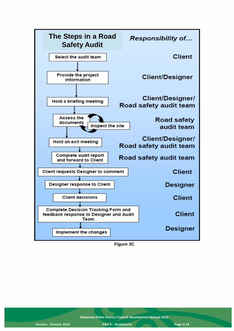
Approval of any roundabout below minimum design criteria will be subject to procedures for a Variation. The application for Variation shall include evidence from the designer supporting that the design will meet capacity, safety and turning movements of intended vehicles. Traffic modelling shall be required that shows that the design can mitigate the effects of traffic generation due to the development. Where applicable, consideration should be given for future network growth and development. This could include intersection modelling using software such as SIDRA. Prior to submitting Engineering Plans the designer shall have a Traffic Safety Audit carried out. The audit shall be undertaken in accordance with the NZ Transport Agency’s “Road Safety Procedures for Projects 2004” (refer also to Figure 3C). Any issues rated as serious must be rectified and items rated important will be evaluated and addressed in a Design Report. The designer shall show on Engineering Plans the visibility splays for each approach of each roundabout, landscaping details, signage, road marking, and state the:
• Design Speed. • Design Vehicle. • LV Distance. • Central Island Diameter. • Circulating Width. • Level of Service.
Note: The NZ Transport Agency’s Safety Audit Procedures is a useful guide.
e) Integrated Transport Assessments An Integrated Transport Assessment (ITA) may be required where road works are proposed. For the specific requirements see “Section 9: Transportation” of the District Plan.
3.7.3 Gradients a) Longitudinal Gradient
Longitudinal gradient will depend on terrain: • Minimum gradient subject to evidence that 0.40% is unobtainable up
to 0.33% • Minimum gradient 0.40% • Maximum gradient (on collector and industrial roads) 8.33% • Maximum gradient (on residential roads) 12.50%

Matamata-Piako District Council Development Manual 2010
Version: October 2015 Part 3 – Roadworks Page 3-17
b) Vertical Curves
For areas where the design speed is ≤ 50 km/h, vertical curves shall have a minimum length of 20 m, except where the grade change is ≤ 1% where the minimum vertical curve length is 10 m. Note: The Austroads “Rural Road Design” publication provides a guide to the design of vertical curves on rural roads.
c) Super-Elevation
Super-elevation will not normally be needed on local and collector roads (where speed restriction is 50km/h or less) and shall not normally be required on curves in rural residential subdivisions.
d) Crossfall
Normal crossfall = 3%. Single crossfall will be considered on carriageways up to 7.0 m where normal crossfall is unobtainable. The maximum longitudinal, or cross sectional slope in turning heads is 6.0%, with the desirable matching normal camber for the pavement type.
3.7.4 Horizontal Curves The minimum centreline radius for industrial roads, residential collector and sub-collector roads is 80 m. The minimum centreline radius for local residential roads is 15 m. Reverse curves are to be separated by an adequate length of straight.
3.7.5 Extra Widening Where the centreline radius is greater than 60 m, extra widening on curves is not required. Where curves are less than 60 m radius, extra widening may be applied to the carriageway. In such cases the minimum berm width shall not be reduced.
3.7.6 Cul-de-Sac Heads In rural and rural residential areas turning heads will be required at the end of all no-exit roads. In all other cases every cul-de-sac should be provided with a carriageway such that the Design Car may turn without reversing. Note: The Austroads “Rural Road Design” publication provides a guide to the design of cul-de-sac turning heads. Provision should also be made, near the end of a cul-de-sac, for three-point turning utilising insets in the kerbline or kerb crossings for the design single unit vehicle. Such kerb crossings shall be specifically designed, such that: • Outside radius turning circle – minimum radius 6.3 m • For simple bulbous head – ” ” 9.0 m

Matamata-Piako District Council Development Manual 2010
Version: October 2015 Part 3 – Roadworks Page 3-18
• For simple bulbous head in industrial roads – ” ” 13.0 m Off-carriageway parking may be provided in cul-de-sac heads (refer to Section 3.5).
3.7.7 Crossfall on Berms Footpath crossfall – typical 2.5% Balance of grass berm crossfall – typical 4.0% Localised footpath crossfalls in the range of 2% to 4% may be permitted where levels make the typical crossfalls impractical. Localised grass berm crossfalls may similarly range between 2% and 10%. Engineering drawings should identify any variances from the typical crossfalls. Berm crossfall shall be satisfactory for vehicle crossings.
3.7.8 Bridges Where bridging is required this shall be subject to specific design. Note: Approval to cross a waterway area shall be obtained from the Waikato Regional Council and the bridge design shall be prepared and certified by a Chartered Professional Engineer. Design calculations shall be provided to Council. Note: The NZ Transport Agency’s “Bridge Manual” standards provide a useful guide.
Matamata-Piako District Council Development Manual 2010
Version: October 2015 Part 3 – Roadworks Page 3-19
Figure 3C
The Steps in a Road Safety Audit

Matamata-Piako District Council Development Manual 2010
Version: October 2015 Part 3 – Roadworks Page 3-20
3.8 Road Pavement
3.8.1 Flexible Pavement Design Pavement design shall be undertaken by an engineer experienced in pavement design. It shall apply to all industrial, local residential roads and any roads of higher classification. a) Design Method Factors to be included in the design are: • Design Period – 30 years • Annual HCV Growth Factor – 3% • Load factor EDA/HCA – 0.6 local roads
– 0.7 collector roads – 0.9 arterial and industrial roads
• % HCV – 2.5% local road – 3.5% collector and higher
classification – 10% industrial roads
The designer shall provide a design report with the engineering drawings, including the following information as a minimum. • Results of soils investigations. • Design assumptions and figures. • QA measures for consideration. Note: The design charts in the State Highway Pavement Design and Rehabilitation Manual, or in the Austroads Pavement Design Guide, provide useful guides. The NZ Transport Agency’s design process shall be for Lower Grade Pavements up to the collector classification and the Premium Flexible Pavements process for roads of higher classification. For Premium Flexible Pavements the NZ Transport Agency’s design document provides a useful guide.
b) CBR Tests All designs shall be based on soaked CBRs. In situ CBR results used for compliance shall be the 10 percentile value of tests.
3.8.2 Subgrade Compliance The subgrade shall be tested for compliance with the CBR and other properties required by the MPDC Infrastructure Code of Practice or as an approved variation to a design method. Subgrade compliance shall be subject to approval by Council before construction of the next pavement layer. Note: The MPDC Infrastructure Code of Practice provides useful guidelines.

Matamata-Piako District Council Development Manual 2010
Version: October 2015 Part 3 – Roadworks Page 3-21
3.8.3 Sub-Base Layer
• Compaction to CBR ≥ 40. Sub-base compliance shall be subject to approval by Council before construction of the next pavement layer. For arterial and collector roads a single layer sub-base or upper sub-base layers shall be constructed from WHAP 65 material only with a minimum thickness of 150 mm.
3.8.4 Basecourse For Arterial and Collector roads the aggregate shall be NZ Transport Agency M4 only. • Compaction to CBR ≥ 80. For all other roads an aggregate complying with the WHAP 40 standard is acceptable.
3.8.5 Pavement Layer Construction Pavement construction below the kerb and channel shall extend 500 mm behind the kerb face.
3.8.6 Surface Sealing Immediately prior to surfacing the basecourse, a 600 mm wide strip adjacent to the channel must be sprayed with an approved sterilising weed killer. Asphaltic concrete on first coat seal is mandatory on industrial carriageways and all cul-de-sac turning circles. On residential cul-de-sac heads, asphalt shall be applied until the carriageway becomes constant width. a) Chip Seal Surfaces
(i) Either: A two coat chip seal comprising a first coat of Grade 3 wet locked with a second coat of Grade 5 is appropriate for most residential roads. Application of the second coat seal shall be delayed until the first coat has had adequate time to mature and should be applied in late summer or autumn. The developer will be responsible for maintenance of the surface until the second seal has been applied and accepted; or:
(ii) An alternative seal standard that complies with the Code of Practice, or such specific designed standard as agreed to by the Council’s Asset Manager – Strategy and Policy.
Note: Council will require a bond from the developer at the time of 224(c) certificate to cover the cost of the second coat seal. The bond will be held until the second seal is completed to the standards set out in the Code of Practice, or as agreed with the Council’s Asset Manager – Strategy and Policy. Note: For both first and second coat chip seal, the bitumen application shall extend over the channel lip, but not by more than 25 mm.

Matamata-Piako District Council Development Manual 2010
Version: October 2015 Part 3 – Roadworks Page 3-22
b) Asphaltic Concrete on First Coat Chip Seal An asphaltic concrete layer must be applied over a waterproofing chip seal of
Grade 5 chip with a residual bitumen application of 1.0 L/m². A NZ Transport Agency M/10 specification Mix 10 is appropriate for residential
applications but industrial sites and arterial roads should consider use of SMA 10. Selection of an appropriate mix for arterial roads and industrial sites should be agreed with the Asset Manager – Strategy and Policy.
Ramp asphalt to existing sealed surfaces. Minimum thickness asphaltic
concrete 25 mm at Mix 10.
3.8.7 Concrete Block Paving The road pavement may be surfaced with concrete block pavers. The concrete blocks shall comply, and laying shall be in accordance with recognized good practice. NZS 3116:2002 “Interlocking Concrete Block Paving” and the RRU Technical Recommendation TR10: “Interlocking Concrete Block Paving” provide useful guides. Pavements specifically for “Light vehicular” use are not acceptable. Pavers shall be 80 mm thick Firth Holland Autumn Tones or Black Sands pavers, or similar approved by Council’s Asset Manager – Strategy and Policy. On carriageways, pavers shall be laid in a herringbone pattern at 45º to the centreline with the long zigzag parallel to the centreline. Note: There are useful guidelines in the MPDC Infrastructure Code of Practice.
3.8.8 Unsealed Pavements in Rural Areas Where approved by the Asset Manager – Strategy and Policy in rural and rural residential areas an unsealed pavement may be constructed. This shall have a minimum compacted thickness of 300 mm of well graded granular material with a minimum soaked CBR of 20. This pavement material shall have sufficient fines to ensure that it does not unravel under the action of traffic. A typical material used on the Council’s unsealed roads is a WHAP 40. A 50 mm minimum compacted thickness wearing course shall then be constructed using WHAP 20 or TNZ B/3 AP 20. Normal camber of unsealed pavements shall be 5% to 6%.
3.9 Road Drainage
3.9.1 Subsoil Drains Where topography dictates or soils are not free draining, subsoil drains will be required behind the kerb as follows: Minimum subsoil pipe size – 110 mm Nexus Minimum depth to pipe invert – 700 mm Minimum width – 300 mm
3.9.2 Batter Drains Batter drains behind the boundary may be required to prevent water entering into or onto the berm. They must be constructed as for 3.9.1 above.

Matamata-Piako District Council Development Manual 2010
Version: October 2015 Part 3 – Roadworks Page 3-23
3.9.3 Drain Outlet Inverts Subsoil and batter drain outlets shall be to catchpits or manholes.
3.9.4 Kerb and Channel, Vertical Kerb and Island Kerb (i) All profiles are to be founded on subgrade with CBR of 7. Where pavement
depth (refer Table 3.1) is greater than 150 mm, profile shall be laid on a minimum of 75 mm of compacted GAP20 or WHAP 20; or:
(ii) The construction shall be in accordance with a specific design approved by the Council’s Asset Manager – Strategy and Policy.
For kerbs with radii tighter than the minimum specified in Table 3.1, or carriageway narrower than standard, “Heavy Duty Kerb and Channel” shall be used. Note: Suitable kerb profiles are detailed in the MPDC Infrastructure Code of Practice.
3.9.5 Catchpits a) For developments where the stormwater connection is direct from each lot to
stormwater drainage pipes, the area drained per catchpit:
- Gross area drained (carriageway, berm and footpath) Maximum 900m² - Area of carriageway Maximum 450m² - Maximum spacing of catchpits 100 m - Maximum spacing of catchpits where private
houses connect stormwater to kerb and channel 60 m b) Preferred location of catchpits:
- At intersections, at the kerbline tangent point - Upstream of pram crossings - At changes of gradient on steep roads - Cul-de-sac heads
c) A double catchpit will be required:
- At the lowest point in a sag vertical curve - At the ends of a cul-de-sac where water falls to the end - On all channels where the gradient is steeper than 5% - Grates shall be the alternative type with bars parallel or perpendicular
to the kerb
3.9.6 Dish Channels For dish channels with footpaths or accessways, concrete is to be on subgrade with CBR not less than 7.
Where possible, the design should avoid a requirement for dish channels. Note: Suitable dish channel profiles are provided in the MPDC Infrastructure Code of Practice.

Matamata-Piako District Council Development Manual 2010
Version: October 2015 Part 3 – Roadworks Page 3-24
3.9.7 Road Drainage in Rural and Rural Residential Areas Channels shall generally be provided for the efficient drainage of surface water and shall be graded to outlets at regular intervals not exceeding 150 m. On steep grades where channels are subject to scouring protection work and outlets at more frequent intervals may be required. Traversable culvert ends should be installed at suitable locations, particularly on arterial and collector roads. Swale drains may be allowed in suitable locations. Culverts, where required, shall be designed in accordance with approved engineering standards. Notwithstanding the outcome of any design calculations, no culvert traversing a road or vehicle entrance shall be smaller than 300 mm in diameter. In non-urban subdivisions where stormwater from the road formation and adjoining properties cannot be discharged via either open channels or a piped system to an approved outlet, the construction of drilled and lined soakholes and/or roadside berm drainage beds is an option. Any application for this type of disposal system must be accompanied by results of soil percolation tests, specifications and design calculations for Council’s approval. The design and testing of these drainage systems shall be carried out by an approved geotechnical engineer. Note: The MPDC Soakage Guidelines provide a useful guide.
3.10 Footpaths
3.10.1 General In general, all roads shall have a footpath on both sides. In the following cases, consideration will be given to one path only: • Where a short cul-de-sac has been deliberately designed to create a slow
speed environment; and • On minor roads in industrial areas where it can be demonstrated that a
second footpath is not justified. In the case of a properly designed shared environment, i.e. where both vehicles and pedestrians have equal priority, a footpath will not be required. In locations with high concentrations of pedestrians, e.g. shopping area, outside schools and leading to schools, footpath widths require design in consultation with the Council’s Asset Manager – Strategy and Policy.
• Footpath crossfall shall be as specified in Section 3.7.7. • Where footpath gradients are steeper than 8.33%, a non-skid surface shall be
provided. • Footpaths shall not be depressed by vehicular crossings. • In new subdivisions, footpaths should generally be constructed in concrete. • Footpaths shall generally be located centrally in the berm – refer to Drawing
DG 302. • All footpaths shall provide for safe and convenient access for blind and
visually impaired pedestrians.

Matamata-Piako District Council Development Manual 2010
Version: October 2015 Part 3 – Roadworks Page 3-25
Note: The NZ Transport Agency’s publication RTX 14 “Guidelines for Facilities that Assist Blind and Visually Impaired Pedestrians” provides full guidelines.
Chip seal footpaths will not be acceptable. Rural residential subdivisions should make provision for pedestrian access along grass berms – refer to Table 3.1.
3.10.2 Footpath Width All footpaths are to be 1.5 m wide.
3.10.3 Concrete Footpaths
• Minimum depth of concrete on 25 mm compacted fine granular material 100 mm
Subgrade preparation is not required to extend beyond the edges of footpath.
3.10.4 Asphalt Surfaced Footpaths
• Minimum depth asphalt 25 mm Mix 10 • Minimum depth basecourse 75 mm GAP 20 • Subgrade CBR Minimum 7 • Timber edging and stakes are required. Note: The MPDC Infrastructure Code of Practice provides guidelines.
3.10.5 Paved Footpaths
• 50 mm Firth Holland Autumn Leaves Pavers or approved equivalent • 25 mm bedding Sanford Park
Subgrade preparation shall extend at least 100 mm beyond the edge of the pavers.
3.10.6 Pram – Wheelchair Crossings Pram crossings shall be provided at all intersections. Details are provided in the MPDC Infrastructure Code of Practice. • Maximum gradient 8.33% The lip of the crossing shall be flush with the invert of the channel.
3.11 Cycle Traffic Provision for cyclists on and off the carriageway shall be subject to scheme plan approvals and designed as required. Provision for cyclists on the carriageway should be in line with “engineering best practice”. The preferred width of an on road cycle lane is 1.5 m. Paths designed for use by cyclists, either exclusively or shared with pedestrians, shall be in line with engineering best practice. The preferred width of shared use paths is 3.0 m.

Matamata-Piako District Council Development Manual 2010
Version: October 2015 Part 3 – Roadworks Page 3-26
Note: The Austroads “Guide to Traffic Engineering Practice Part 14: Bicycles” publication provides a useful guide.
3.12 Vehicle Crossings
3.12.1 Definitions In this section the following definitions apply. Should a definition be in conflict with the definitions in the District Plan, then the District Plan shall prevail. Road Intersections Public or private roads, rights of way and vehicle
entrances generating more than 100 traffic movements per day shall be treated as an intersection.
Entrance Up to 2 individual vehicle entrances adjacent to each
other. Vehicle Crossing Vehicle access from a public or private road to public or
private land or right of way. Speed or Design Speed Means the 85 percentile of the normal operating speed
on the through road.
3.12.2 Vehicle Crossings in Urban Areas Vehicle crossings shall be provided where an entrance requires that vehicles are crossing the kerb and berm.
Vehicle crossings shall be provided as part of the subdivision or development for private ways and to lots with road frontage less than 5 m in width. Crossings shall be designed so that the footpath is continuous through the site. In particular: • Vehicle crossings shall not interfere with the profile of the footpath or the berm
except that minor filling may be permitted between the property boundary and the footpath. No retaining walls or structures are permitted to encroach onto the berm and no lowering of the berm is permitted.
• Vehicle crossings shall be constructed with the same material as the adjacent footpath except that for chipsealed or slurry sealed footpaths, the crossing shall be surfaced with asphaltic concrete. Where there is no existing footpath the crossing may be surfaced with concrete or asphalt.
• The vehicle crossing standards apply to the full width of the berm between the kerb and road boundary.
• When constructing a new vehicle crossing, if an existing footpath exists, the footpath is to be cut out and reconstructed to the vehicle crossing standard.
• Where the existing kerb and channel is cracked, the kerb and channel is to be removed and incorporated into the vehicle crossing construction works.
• Chip seal surface applies only in rural environments. • Sub-grade and sub-base preparation is to extend 100 mm beyond the edges
of the crossing. • Industrial vehicle crossings shall be designed with consideration given to their
rate of usage, loading, and the type of activity undertaken on the site.

Matamata-Piako District Council Development Manual 2010
Version: October 2015 Part 3 – Roadworks Page 3-27
For properties at intersections, the vehicle crossing should be off the minor road rather than the major road. Residential crossings shall possess the following dimensions: • Single width entrances shall use a crossing width and cut down length of
2.5 m. • Double width entrances shall use a crossing width and cut down length of
5.4 m. Business and Industrial crossings shall possess the following dimensions: • Single width entrances shall use a crossing width and cut down length of
3.5 m. • Double width entrances shall use a crossing width and cut down length of
6.0 m. All urban crossings shall be: • Located to comply with:
o Minimum sight distance standards at vehicle crossings – Table 3-A; o Minimum vehicle crossing separation standards – Table 3-B; and: o Standards for minimum separation between vehicle crossings and
intersections – Table 3–C; and: • Designed and constructed in accordance with Drawing DG 308. Note: The MPDC Infrastructure Code of Practice provides details for the construction of crossings.
3.12.3 Rural and Rural-Residential Vehicle Crossings Vehicle crossings in rural and rural-residential areas shall be constructed to the same standard as the road they come off. Design shall be as per: • Drawing DG 307 (District Roads); or: • Diagrams C, D, or E (State Highways) as required by the table below:.
*Equivalent car movements per day. This is calculated either as an average or as weekly average whichever is greater, to cater for the seasonal peaks. Minimum sight distance shall be in accordance with Table 3-A.
Access drives shall be formed and maintained so as to adequately control stormwater and to prevent materials such as mud, stones, chip gravel or stock effluent being carried onto public road. Where a large vehicle entrance is proposed off a roadway with a carriageway width of 6 metres or less then carriageway widening will be required as part of the
Type of traffic using accessway (more than one slow, heavy or long vehicle movements per
week?)
Volume of traffic using accessway
(ecm/day*)
Volume of traffic using state
highway (vpd)
Accessway type
No 1–30 <10,000 Diagram C ≥10,000 Diagram D
31–100 <10,000 Diagram D ≥10,000 Diagram E
Yes 1–30 All Diagram D 31–100 All Diagram E

Matamata-Piako District Council Development Manual 2010
Version: October 2015 Part 3 – Roadworks Page 3-28
development. The widening is required to provide a total carriageway width of 6 metres for a length of 15 metres. 5:1 tapering shall then be used to terminate back to the existing edge of seal. Note: For further information regarding road widening see MPDC Infrastructure Code of Practice. Separation distances between rural entranceways and to intersections are to be as shown in Tables 3-B and 3-C. No new entrances shall be located closer than 30 metres from a rail crossing without the approval of the NZ Railways Corporation. Table 3-A: Minimum Sight Distance Standards at Vehicle Crossings (All Zones) 85th percentile
operating speed
Minimum Sight Distance Standard Significant Roads All other
Roads State Highways
(> 10,000 vpd)
State Highways
(<10,000 vpd) Tahuna-
Ohinewai Road;
Paeroa-Tahuna Road; Morrinsville-Tahuna Road
40 km/h Not applicable Not applicable 28 m 50 km/h 125 m 89m 44 m 60 km/h 160 m 113m 63 m 70 km/h 220 m 140m 86 m 80 km/h 305 m 170m 115 m 90 km/h 400 m 203m 140 m 100 km/h 500 m 240m 170 m 110 km/h 500 m 282m 210 m

Matamata-Piako District Council Development Manual 2010
Version: October 2015 Part 3 – Roadworks Page 3-29
Table 3-B: Minimum vehicle crossing separation standards
85th percentile operating
speed
Minimum Spacing between Vehicle Crossings (b – Figure 3.2)
Significant Roads Arterial Roads
Collector and Local Roads State
Highways (> 10,000
vpd)
State Highways (<10,000
vpd) Tahuna-
Ohinewai Road;
Paeroa-Tahuna Road;
Morrinsville-Tahuna Road
50 km/h 125 m 15m 15 m One crossing per title irrespective of spacing and 15m minimum spacing for second or multiple
entrances 60 km/h 160 m 15m 15m One crossing per title irrespective
of spacing and 15m minimum spacing for second or multiple
entrances 70 km/h 220 m 40m 40m One crossing per title irrespective
of spacing and 30m minimum spacing for second or multiple
entrances 80 km/h 306 m 40 m 40m One crossing per title irrespective
of spacing and 30m minimum spacing for second or multiple
entrances 90 km/h 400 m 100 m 100m One crossing per title irrespective
of spacing and 30m minimum spacing for second or multiple
entrances 100 km/h 500 m 200 m 200m One crossing per title irrespective
of spacing and 80m minimum spacing for second or multiple
entrances 110 km/h 500 m 200 m 200m One crossing per title irrespective
of spacing and 80m minimum spacing for second or multiple
entrances

Matamata-Piako District Council Development Manual 2010
Version: October 2015 Part 3 – Roadworks Page 3-30
Table 3-C: Standards for minimum separation between vehicle crossings and intersections
85th
percentile operating
speed
Minimum Spacing between Vehicle Crossings and Intersections Significant Roads Arterial Roads Collector
and Local Roads
State Highways (> 10,000
vpd)
State Highways (<10,000 vpd)
Tahuna-Ohinewai Road;
Paeroa-Tahuna Road;
Morrinsville-Tahuna Road
Crossing on state highway or side
road (a and c in
Fig 3.2)
Crossing on state highway (a in Fig
3.2)
Crossing on side
road (c in Fig
3.2)
Crossing on
arterial road
(a in Fig 3.2)
Crossing on side
road (c in Fig
3.2)
Crossing on either main or
side road (a or c in Fig
3.2)
50 km/h 125 m 30 m 20 m 30 m 20 m 20 m 60 km/h 160 m 30 m 20 m 30 m 20 m 20 m 70 km/h 220 m 30 m 20 m 30 m 20 m 20 m 80 km/h 305 m 100 m 45 m 100 m 45 m 45 m 90 km/h 400 m 100 m 45 m 100 m 45 m 45 m
100 km/h 500 m 200 m 60 m 200 m 60 m 60 m 110 km/h 500 m 200 m 60 m 200 m 60 m 60 m
3.12.4 Rural and Rural-Residential Vehicle Crossings – Seal Distance from the Carriageway to the Property Boundary For new vehicle entranceways/crossings or those over which there is a change or increase in intensity in scale of use, they should be constructed in accordance with Drawing DG 307. The seal distance shall be determined based on the following categories: • Visibility at the Entranceway • Gradient of Entranceway • Vehicles Per Day Past the Entranceway • Posted Speed Limited • Locality of Other Entranceways • Effects of Other Entranceways • Width of Road The following assessment matrix shall determine the minimum seal distance required from the edge of the carriageway (measured at the centrepoint of the crossing):
Category Criteria Weighting Evaluation Explanation
Visibility at Entranceway
Excellent visibility 10 More than 300 m
In accordance with DM 5 Meets requirement as per DM
Poor visibility 0 Does not meet

Matamata-Piako District Council Development Manual 2010
Version: October 2015 Part 3 – Roadworks Page 3-31
requirement
Gradient of Entrance (12 m back)
Flat gradient 20 Gradient between 1:12 and 12:1
Steep gradient 0 Gradient steeper than 1:12 and 12:1
VPD past the Entranceway
Very low volume traffic 30 Less than 150 Low to medium traffic volume 20 150–500
Medium to high traffic volume 10 500–1500
Very high traffic volume 0 above 1500 Posted Speed Limit
Low speed limit 5 less than 100 km/h
Open road 0 100 km/h or more
Locality of other Entranceways
Entrances are well away from others 5 Meets requirement
as per DM Very close to other entranceways 0 Does not meet
requirement
Effects of Activity on Entranceway
Only cars use it 15 Light vehicles only Occasional stock/delivery truck 10 Occasional
stock/delivery truck
Tanker and occasional stock truck 5
Tanker and occasional stock
truck
Higher use than tanker and occasional stock truck
0
Higher use than tanker and
occasional stock truck
Width of Road (sealed carriageway)
Wide road way 15 Wider than 7 m Medium width road way 10 Between 7 and 6 m
Narrow road way 0 Less than 6 m
Total 100 Scoring Score >70 1 m of seal required Score 50–70 3 m of seal required Score <50 5 m of seal required Exclusions For roads that are not sealed no seal shall be required for the entranceway. For rights of way or access legs serving 3 or more lots the seal from the carriageway shall extend to the property boundary.

Matamata-Piako District Council Development Manual 2010
Version: October 2015 Part 3 – Roadworks Page 3-32
Figure 3.2

Matamata-Piako District Council Development Manual 2010
Version: October 2015 Part 3 – Roadworks Page 3-33
3.13 Berms Berms shall accommodate footpath, road lighting, underground services, landscaping and grass areas. The minimum width of berm shall be 4.5 m except for private ways and shared environments. (For layout see Drawings DG 300 and DG 302.)
• Minimum compacted depth of topsoil 75 mm. • Approved grass seed = Perennial Rye • Sowing Rate = 1.5 kg/100 m² Berms are to be mown during the defects liability period as well as prior to take over by Council. All landscape planting design and implementation within the road reserve shall be as per Part 7 – Street Landscaping. This includes, but is not restricted to the Dedicated Tree Planting Corridor referenced in Section 7.2.2.2 that requires a minimum 900 mm wide service free corridor within the berm.
3.14 Road Lighting Road lighting is to be provided on all roads, service lanes, cycle ways, footpaths through reserves and other pedestrian accessways / areas where the lighting is (or will be) managed by the Council and connected to the Electricity Network Operator’s road lighting network.
3.14.1 General Requirements The lighting design shall maximise safety and efficiency while minimising the life cycle cost and impact on the environment. It is important to design the lighting to blend in with adjacent road lighting, complement the neighbourhood character and – as far as is reasonably practicable – minimise the impact on the neighbouring properties and environment with regard to aesthetics, glare and spill light. For rural intersections where the total volume on all legs has an AADT > 500, intersection flag lighting shall be used. In rural areas where design speeds are greater than 70 km/h or in areas where there is an obvious hazard slip-base frangible approved lighting columns shall be used.
3.14.2 Lighting Parameters Lighting installations shall be designed by a qualified lighting designer who is familiar with the requirements of AS/NZS 1158:2005. Note: Designers shall also be familiar with the relevant technical specifications included in the MPDC Infrastructure Code of Practice. The following sections apply to the lighting design:
3.14.2.1 Category V (Traffic Route) Lighting Category V lighting shall provide a lit environment conducive to the safe and comfortable movement of vehicular and pedestrian traffic at night and

Matamata-Piako District Council Development Manual 2010
Version: October 2015 Part 3 – Roadworks Page 3-34
discourage illegal acts. The visual requirements of motorists shall predominate.
3.14.2.2 Category P (Local Roads and Pedestrians Area) Lighting Category P lighting shall be designed to help pedestrians to orientate themselves and detect potential hazards, and discourage fear of crime against the person. The designer shall take into consideration the Category P requirements and the principles of “Crime Prevention through Environmental Design”. To maximise efficiency and minimize the number of lights installed the following Table applies:
Legal Road Width (m) 20 18 16 14 12
Minimum design spacing P3 (m)
40 45 50 Consult with Council
Consult with Council
Minimum design spacing P4 (m)
54 55 55 Consult with Council
Consult with Council
As a guide the following are the preferred mounting heights for the luminaires: • 6.0 m in residential areas, and • 7.0 m in industrial areas.
3.14.2.3 Traffic Management Devices Traffic management devices shall be considered as an integral part of the lighting design and appropriate standards shall be applied. Lighting of traffic management devices shall be designed to support the purpose of the device: • Where the device is intended to slow traffic, lighting may need to
be installed to a higher standard than normal for that area. This will be to provide sufficient visibility to alert drivers of the presence and speed constraint of the device.
• Where the device is intended to deter through traffic, the device may be identified by signage or by road lighting.
3.14.2.4 Column Locations Ideally lighting columns should be positioned in line with the side boundary between properties; however these locations do not always coincide with the spacing requirements of the lighting design. If an adjacent property has not been developed (e.g. a new subdivision) and the column cannot be positioned in line with the common boundary, locate the column at least six metres from the boundary to allow for a future vehicle entrance.
Position columns at least one metre away from a vehicle entrance or kerb cut-down. Keep columns clear of any tree canopies in the road or in adjacent properties to prevent shading of the luminaire. Trees in a legal

Matamata-Piako District Council Development Manual 2010
Version: October 2015 Part 3 – Roadworks Page 3-35
road or on Council land must be at least six metres away from lighting columns and more clearance may be necessary for some tree species or if the tree is protected. Consider the Council requirements for working near to existing trees when locating lighting columns. When positioning a column against the building line, ensure that it is installed within the legal road or on Council land, and not in private property. Where possible, columns should be located close to reserve entrances, bus stops and other open spaces to improve safety. Consider traffic safety when placing lighting columns, especially when they are on or near bends, intersections, threshold treatments, road humps and roundabouts.
3.14.2.5 Column Installation and Foundations Columns shall be installed as per the manufacturer’s requirements. If the road is at a different level from where the column is being located, design for columns that will achieve the correct mounting height above the road surface to ensure the installed lighting complies with the design requirements. For each light type the mounting height must be uniform and consistent. Where the longitudinal grade may exceed 1 in 6 or the cross-fall of a road may exceed 6%, it may not be possible to service the light from a cherry-picker. In these situations discuss alternative column types with Council (e.g. columns that will allow the light to be serviced via a ladder). When a special foundation is required provide a producer statement when applying for engineering approval. Include a hold-point for construction to allow inspection of the foundation before concrete is poured. When columns requiring special maintenance visits are specified (e.g. frangible – shear base columns), provide Council with a maintenance plan detailing maintenance intervals and work/inspections that need to be carried out.
3.14.2.6 Lighting Equipment The design life of equipment shall be as shown in the following table:
Component Design Life Columns (concrete and steel) 40 years Outreach arms 40 years Luminaires 20 years Lamps HPS MH Fluorescent
16,000 hours 12,000 hours 12,000 hours
Painted/powder coated surfaces 10 years

Matamata-Piako District Council Development Manual 2010
Version: October 2015 Part 3 – Roadworks Page 3-36
Notes: All bolts and fittings shall have the same life expectancy as the component. The design life of luminaires is the expected service life based on manufacturer’s data and expected 5% failure rate. Note that lamp manufacturers may publish average rated life at 50% failure rate; this is too long if a lamp replacement programme is implemented. Typical operating hours of road lighting networks within New Zealand is approximately 4,200 hours per annum. Luminaires, columns and outreach arms that are used in new schemes should be compatible with adjacent lighting and, where practicable, visually match the existing road lighting. For efficient maintenance, the types of lighting equipment used are usually limited to those already in the lighting network. Introduction of new equipment requires approval from Council prior to use. Provide detailed information on the design drawings about the columns, outreach arms, luminaires and lamps proposed to be used in the scheme.
3.14.2.7 Category P Lighting in Cycleways and Paths in Reserves Category P lighting for cycleways and paths in reserves shall be designed to help users to orientate themselves and detect potential hazards. The designer shall take into consideration the Category P requirements and the principles of “Crime Prevention through Environmental Design”. The minimum mounting height is 5.5 m and the maximum is 7.5 m. However, if the lights are located near trees it may be appropriate for the lights to be mounted at a lower height to illuminate underneath the tree canopy and avoid shadowing. In this case a minimum mounting height of 4.5 m may be accepted.
3.14.3 Circuit Cabling Design of cabling, including control method shall be in accordance to the specifications and requirements of the local Network Owner.
3.14.4 Design Check In order to demonstrate compliance with the required standard a PS1 design certificate shall be provided by the designer. The documentation listed in Appendix C of AS/NZS1158: 2005 Part 1.1 and Part 3.1 will meet this requirement.
3.14.5 Audit Lighting System Upon installation and commissioning the streetlights may be audited by Council. This final audit will ensure that the asset’s performance and quality of the work comply with Council’s requirements.
3.15 Signs and Roadmarking All regulatory signs and road name signs shall be provided. White powder coated steel poles shall be used.

Matamata-Piako District Council Development Manual 2010
Version: October 2015 Part 3 – Roadworks Page 3-37
Proposed road marking shall be shown on the drawings. Note: The MPDC Infrastructure Code of Practice provides a guide to the location or mounting of signs and the requirements for road marking.
3.16 Service Lanes Minimum carriageway width is 6.0 m. Carriageway is to have concrete edging both sides. Stormwater is to be collected and disposed of. Specific geometric and pavement design is required. Carriageway is to be asphalt.
3.17 Privateways
3.17.1 Urban Residential Privateways For layout refer to Drawing DG 301. For dimensions and sealed pavement structure, see Table 3.1. The minimum inside radius of curves shall be 9.0 m. The gradient shall not exceed 1:6 unless approved by the Engineer. Where the gradient exceeds 1:6, such safety provisions as may be required by the Engineer shall be provided. Privateways longer than 75 m shall provide a passing bay. Particular design requirements are provided in Table 3.1. Stormwater shall be collected and piped into the stormwater collection system. Stormwater shall not discharge across the vehicle crossing from the privateway to the road. Vehicle crossing to privateway shall be designed and constructed in accordance with Section 3.12 and Drawings DG 301 and DG 308.
3.17.2 Rural Residential Privateways Particular design requirements are provided in Table 3.1.
3.17.3 Right of Way Producer Statement A producer statement shall be provided for the design and construction of rights of way with a length of more than 20 metres. On completion of construction the applicant shall provide a producer statement (PS4 or similar) signed by a suitably qualified person. Note: It is recommended that you discuss with Council prior to work being undertaken to determine who is considered suitable for a particular situation.
3.18 Parking Bays Parking bays shall be constructed to the same standard as the road and continue the carriageway crossfall. If the parking bay is offset from the road carriageway, a dish channel could be used.

Matamata-Piako District Council Development Manual 2010
Version: October 2015 Part 3 – Roadworks Page 3-38
3.19 Features and Berm Furniture
3.19.1 Feature Walls Feature walls will be permitted providing that the following criteria are adhered to: • All permanent structures shall be erected on land other than road reserve. • The structure must comply with all building consent and District Plan
requirements. • The structure shall be constructed from durable materials such as concrete,
brick, stone, metal, timber. • No lighting shall be installed that could potentially be hazardous to motorists
or irritating to residents, nor shall it compromise the required road lighting. • Plaque type name plates may be attached to the walls provided the sign
complies with the District Plan. • No services shall be affected by the location and construction of the structure. • All maintenance costs (including electricity supply if required) shall be at the
expense of the owner of the land upon which the structure is sited. • The structures shall not create traffic safety problems. • The structure shall be set to permanent levels. • Prior to construction, a safety audit shall be carried out. The feature walls
shall be constructed in accordance with the recommendations of the safety audit.
3.19.2 Berm Furniture Structures or features which are not part of signage or traffic control will not be permitted on road.
3.20 Pedestrian Accessways Access ways may be required to link one road to another in order to improve pedestrian and cyclist access. • Access ways shall be a minimum of 5 m wide (boundary to boundary). • Access ways shall be provided with lighting to P1 standard. • Footpaths shall be a minimum of 3 m wide. • Access paths bounded by private lots and linking between public roads shall
be fenced both sides by the Developer. The fence shall be a minimum of 1.2 m high, 3 rails with timber palings.
• Access ways should have sight lines from one end to the other. • The fence shall provide security for the resident and allow passive
surveillance of the walkway. Note: All fencing shall meet the principles of “Crime Prevention Through Environmental Design” (CPTED). The MPDC Guide to Urban Design Considerations provides useful information.
3.21 Road Design Quality Assurance The Council requires the following information to be submitted with the engineering drawings: • A specific Roading Engineering Drawing Quality Assurance checklist shall be
completed. • The name of the appointed representative experienced in
development/construction work with whom all discussions and

Matamata-Piako District Council Development Manual 2010
Version: October 2015 Part 3 – Roadworks Page 3-39
correspondence relating to engineering matters will be undertaken with Council stall shall be identified.
• A Quality Management Plan that shall be compiled to a level of sophistication appropriate to the nature and scale of the proposed works. In the case of minor works this may entail documentation of an inspection by a suitably qualified person. More extensive works will require an appropriate level of quality management.
The Council is to provide a set of standard checklists and quality assurance management plan.
3.22 Verandahs Where required by the District Plan, verandahs shall be provided to meet the dimensions shown in Figure 3.3.
Figure 3.3 – Verandah Details
Verandahs shall be constructed in accordance with the above diagram and the following: • The outer edge of the verandah shall be set back by 0.5 m from the pavement
kerb. • Continuous with any adjacent verandahs to provide continuity of pedestrian
shelter. • An appropriate height above the footpath to provide pedestrians with shelter
from rain at a height of no less than 2.8 m and no higher than 3.5 m. • Of solid construction. • Any sign below the verandah shall be no less than 2.5 m from the footpath
level and it’s size shall comply with District Plan requirements. • If under-verandah lighting is required, all fittings shall be vandal proof.
PAVEMENT
0.5m
S IGNAGE
KERB
POST
FOOTPATH
0.4m
SIGNAGE
min 2.5m min 2.8m
SIGNAGEBUILDING
max 0.6m
Not to scale

Matamata-Piako District Council Development Manual 2010
Version: October 2015 Part 3 – Roadworks Page 3-40
• Awnings shall be a minimum of 2.5 m above the footpath level. • All drainage pipes for stormwater from the verandah shall not be exposed and
be contained within the post or adjacent structure. • Any new posts shall be located as indicated on the drawing above and shall
not interfere with any pedestrian or vehicular access.
3.23 Stock Crossings
3.23.1 General Where there is a need for stock to cross a road on a regular basis due to a farm
being located astride the road then the decision as to whether an underpass will be required will be made by the use of the chart in Figure 3.4.
Figure 3.4 – Stock Crossings
3.23.2 Stock Crossing If a Stock Underpass is not required, a mat shall be placed over the road crossing used by stock for dairy farm units and shall comply with the following:
• That stock shall not be driven across the road during the hours of darkness. • The stock crossing shall be maintained and operated as to ensure that the road
is clean at all times and to eliminate damage to the road carriageway. • That the area between the farm gates and the road carriageway on both sides of
the road shall be formed to a hard standing metal surface. • At the request of Council staff, any damage to the road formation, seal, or road
drainage attributable to the stock crossing shall be made good at the owners expense.
• The entry and exit points of the stock crossing shall be directly opposite each other.
• The stock crossing shall be located at sites which achieve visibility distances.

Matamata-Piako District Council Development Manual 2010
Version: October 2015 Part 3 – Roadworks Page 3-41
• The mat width shall extend 2 m wide either side of the gateway.
3.23.3 Stock Underpass If a Stock Underpass is required it shall comply with the following: • The Stock Underpass length shall be a minimum of 7 m either side of the centre
of the road. However the final length of the underpass will depend on traffic volume, seal and shoulder width, in situ soil conditions, depth and angle of underpass, construction of wingwalls, roadside drainage requirements, traffic safety/risk assessment or any other site specific factors. The developer shall discuss the requirements for the underpass with the Asset Manager – Strategy and Policy before finalising the design.
• The Underpass shall be designed in accordance with the NZ Transport Agency Bridge Manual (September 2004) to HN-HO-72 loading.
• The minimum cover for the underpass shall be as per manufacturing specifications.
• The Underpass shall allow for drainage of the underpass floor and surrounding ground.
• Retaining/wing walls shall be designed to retain the embankment fill. • Any cut slopes shall be laid back to a safe slope or retained with a properly
designed retaining wall. • A producer statement from the designer of the proposed underpass structure
shall be submitted. • Barrier rails to warn approaching traffic of the hazard shall be installed. The
ends may require bridge end or hazard markers as determined by Council’s Roading Engineer. A white painted post and rail fence (minimum two coats white acrylic paint) shall be erected from the property boundary fence around the top of the batter of the underpass and back to the boundary fence. The fence shall consist of a minimum of three rails made with timber posts with a diameter of 150 mm and rails of 150 mm by 50 mm.
• The ends of the underpass shall be sufficiently retained to prevent the loss of fill material and stormwater into the underpass openings.
• The pavement shall be reinstated to the same line and levels that existed prior to the construction of the underpass. The pavement material shall comply with Section 3.8 – Road Pavement.
• The applicant shall be responsible for locating and managing all services within the road reserve in vicinity of the works.
• A suitably qualified Engineer shall sign off the design, construction works and the finished Stock Underpass. (Note: It is recommended that you discuss with Council prior to work being undertaken to determine who is considered suitable for a particular situation.)
• A suitably qualified Contractor who shall construct the Stock Underpass, having the relevant health and safety procedures and having undertaken similar works in the past.
3.23.4 Stock Crossings / Stock Underpasses of the Rail Network In addition to the requirements of 3.23.2 and 3.23.3 above, if a new stock crossing or underpass is proposed over/under the railway premises the applicant shall obtain the written approval of the NZ Railways Corporation.

Matamata-Piako District Council Development Manual 2010
Version: October 2015 Part 3 – Roadworks Page 3-42
3.24 Road–Rail Intersections Where a railway and a road intersect on the same level, no building or other obstruction which may block the sight lines shall be permitted within an area bounded as set out in Figures 3.5 and 3.6, and Tables 3.5 and 3.6.
3.24.1 Level Crossing Sight Triangles and Explanations Developments near Existing Level Crossings It is important to maintain clear visibility around level crossings to reduce the risk of collisions. All the conditions set out in this standard apply during both the construction and operation stages of any development.
Approach sight triangles at level crossings with Stop or Give Way signs On sites adjacent to rail level crossings controlled by Stop or Give Way Signs, no building, structure or planting shall be located within the shaded areas shown in Figure 3.5. These are defined by a sight triangle taken 30 metres from the outside rail and 320 metres along the railway track. Figure 3.5: Approach Sight Triangles for Level Crossings with “Stop” or “Give Way” Signs Advice Note: The approach sight triangles ensure that clear visibility is achieved around rail level crossings with Stop or Give Way signs so that a driver approaching a rail level crossing can either:
• See a train and stop before the crossing; or • Continue at the approach speed and cross the level crossing safely.
Of particular concern are developments that include shelter belts, tree planting, or a series of building extensions. These conditions apply irrespective of whether any visual obstructions already exist.
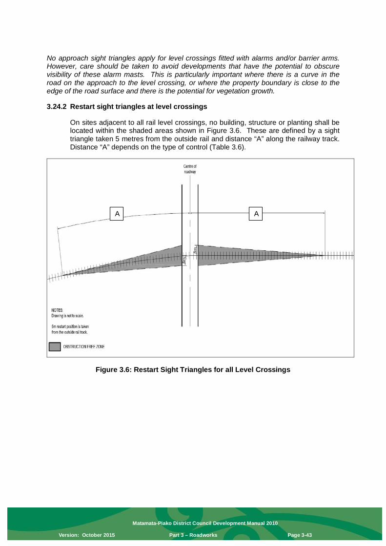
Matamata-Piako District Council Development Manual 2010
Version: October 2015 Part 3 – Roadworks Page 3-43
No approach sight triangles apply for level crossings fitted with alarms and/or barrier arms. However, care should be taken to avoid developments that have the potential to obscure visibility of these alarm masts. This is particularly important where there is a curve in the road on the approach to the level crossing, or where the property boundary is close to the edge of the road surface and there is the potential for vegetation growth. 3.24.2 Restart sight triangles at level crossings
On sites adjacent to all rail level crossings, no building, structure or planting shall be located within the shaded areas shown in Figure 3.6. These are defined by a sight triangle taken 5 metres from the outside rail and distance “A” along the railway track. Distance “A” depends on the type of control (Table 3.6).
Figure 3.6: Restart Sight Triangles for all Level Crossings
A A

Matamata-Piako District Council Development Manual 2010
Version: October 2015 Part 3 – Roadworks Page 3-44
Table 3.6: Required Restart Sight Distances For Figure 3.6
Required approach visibility “A” along tracks (m)
Signs only Alarms only Alarms and barriers 677 m 677 m 60 m
Advice Note: The restart sight line triangles ensure that a road vehicle driver stopped at a level crossing can see far enough along the railway to be able to start off, cross and clear the level crossing safely before the arrival of any previously unseen train. Of particular concern are developments that include shelter belts, tree planting, or a series of building extensions. These conditions apply irrespective of whether any visual obstructions already exist. Notes: 1. Figures 3.5 and 3.6 show a single set of rail tracks only. For each additional set of tracks
add 25 m to the along-track distance in Figure 3.5, and 50 m to the along-track distance in Figure 3.6.
2. All figures are based on the sighting distance formula used in NZ Transport Agency’s Traffic Control Devices Manual 2008, Part 9 Level Crossings. The formulae in this document are performance based; however the rule contains fixed parameters to enable easy application of the standard. Approach and restart distances are derived from a: • train speed of 110 km/h • vehicle approach speed of 20 km/h • fall of 8 % on the approach to the level crossing and a rise of 8 % at the level
crossing • 25 m design truck length • 90° angle between road and rail

Matamata-Piako District Council Development Manual 2010
Version: October 2015 Part 3 – Roadworks Page 3-45

Matamata-Piako District Council Development Manual 2010
Version: October 2015 Part 3 – Roadworks Page 3-46
Note: Drain is required only when surface water from private property will otherwise flow onto the footpath
Note: Drain is required only when surface water from private property will otherwise flow onto the footpath.

Matamata-Piako District Council Development Manual 2010
Version: October 2015 Part 3 – Roadworks Page 3-47

Matamata-Piako District Council Development Manual 2010
Version: October 2015 Part 3 – Roadworks Page 3-48
MATAMATA-PIAKO DISTRICT COUNCIL
MATAMATA-PIAKO DISTRICT COUNCIL

Matamata-Piako District Council Development Manual 2010
Version: October 2015 Part 3 – Roadworks Page 3-49

Matamata-Piako District Council Development Manual 2010
Version: October 2015 Part 3 – Roadworks Page 3-50

Matamata-Piako District Council Development Manual 2010
Version: October 2015 Part 3 – Roadworks Page 3-51

Matamata-Piako District Council Development Manual 2010
Version: October 2015 Part 3 – Roadworks Page 3-52

Matamata-Piako District Council Development Manual 2010
Version: October 2015 Part 3 – Roadworks Page 3-53

Matamata-Piako District Council Development Manual 2010
Version: October 2015 Part 3 – Roadworks Page 3-54

Matamata-Piako District Council Development Manual 2010
Version: October 2015 Part 3 – Roadworks Page 3-55

Matamata-Piako District Council Development Manual 2010
Version: October 2015 Part 3 – Roadworks Page 3-56
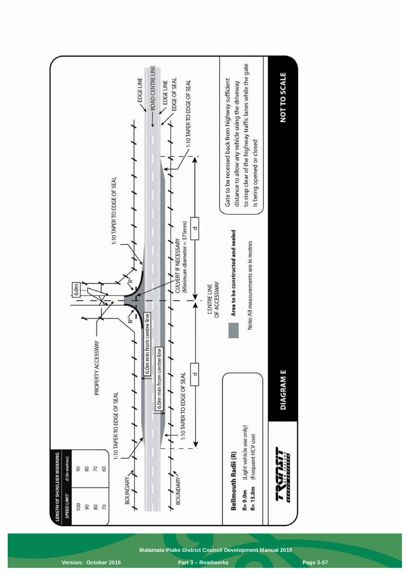
Matamata-Piako District Council Development Manual 2010
Version: October 2015 Part 3 – Roadworks Page 3-57

Matamata-Piako District Council Development Manual 2010
Version: October 2015 Part 3 – Roadworks Page 3-58

Matamata-Piako District Council Development Manual 2010
Version: October 2015 Part 4 – Stormwater Drainage Page 4-1
Part 4 – Stormwater Drainage
4.0 Introduction This Manual sets out the basic design principles for drainage of stormwater.
4.1 General All lots shall be provided with a means of stormwater drainage at or within the lot boundary. Where the property in question already has a connection to a public stormwater system then that connection can continue to be used, but the discharge through this connection shall be limited to the discharge rates from the pre-developed site and any excess discharge rate (e.g. overland flow) created shall be dealt with by the development to the pre-development disposal rates. Developers should be familiar with the MPDC Stormwater Management Bylaw. In some cases a new connection to a public stormwater system may be approved by Council. In those cases the design of the new stormwater system shall conform with the MPDC Development Manual requirements. In all cases where stormwater is to be disposed through on-site soakage then the developer will find that the MPDC Soakage Design Procedures and Guidelines (known as the Soakage Guideline) provides a useful reference guide. This guideline is to assist designers to provide a soakage system that will deal with the calculated stormwater discharge rates. It also allows for convenient maintenance of the soakage system so that there can be confidence that it will continue to work effectively for the long term. In cases where connection to a public stormwater system is not available and ground soakage is not adequate then an alternative system may be approved. Council opinion is that ‘wet pond’ type detention dams should be avoided The design intention is to incorporate natural environment-based systems within new works. A natural environment-focused stormwater system may include features such as groundwater recharge, overland flow, open drains, and storm peak mitigation through dams, lake and wetland systems. Key objectives are:
1. Optimise the amount of stormwater entering the piped drainage system; 2. Facilitate groundwater recharge; 3. Cover the immediate needs as well as those of foreseeable future
developments; 4. Avoid detrimental effects on downstream properties; 5. Build infrastructure to minimise lifecycle maintenance costs.
Where stormwater is designed to flow into existing drainage systems, there shall be no increase in peak discharge flow rates from the construction of the subdivision or development. Where a stormwater system is proposed for the collection and discharge of stormwater within the land being developed, it shall also have capacity to deal with drainage from the entire catchment upstream of the development site.

Matamata-Piako District Council Development Manual 2010
Version: October 2015 Part 4 – Stormwater Drainage Page 4-2
Stormwater proposals must take into account the requirements of Council’s current stormwater discharge consents from the Regional Council. All proposals must be consistent with the conditions of these consents including requirements for low impact design principles, stormwater management devices and best practicable options. Where the discharge is to an existing Council pipe network it is Council’s responsibility to assess compliance for all new connections to its pipe network. It will require the same conditions as applying to any new municipal stormwater system diversion or discharge activities. In particular it will require that the new diversion or discharge does not increase peak discharge rates to receiving waters above that which would occur at the time of the application for Council’s current discharge consents – unless it is demonstrated that there shall be no adverse effects on the environment or downstream properties as a result of such increase. Acceptance will also be subject to compliance with the requirements for connections to the municipal stormwater system. Where the new stormwater will discharge to other than an existing Council pipe network, the subdivider or developer is required to obtain appropriate resource consents for discharge for the work from the regional council in the Developer’s name. Evidence of this is required before the subdivision can be approved. If Council is to take over the finished system, it will need to add the discharge to its own consent at the time of transfer. The consent must therefore specifically state that the work will comply with the requirements for a new municipal discharge as set out in Council’s Comprehensive Storm Water Discharge Consent (refer to Section 4.2 below). Secondary flow paths shall be provided and must be able to cater for a minimum of a 1 in 100 year return period storm. Secondary flow paths within the development must be protected by an easement registered against the titles affected. Where secondary flow paths are not feasible the piped system must cater for a minimum of a 1 in 100 year return period storm. This shall also ensure that the peak flow rate from the developed site does not exceed the 100 year pre-development peak flow rate. Where disposal is to ground soakage with no available secondary flow path, the soakage system must cater for a 1 in 100 year return period storm.
4.2 MPDC Stormwater Management Bylaw The intention of stormwater management bylaws is to manage stormwater within the Matamata-Piako District so as to protect people, property and the environment by minimising the impact of flooding, erosion and environmental pollution.
Stormwater management bylaws are in addition to controls on stormwater imposed by the Waikato Regional Council and the Matamata-Piako District Council under the Resource Management Act 1991, the Building Act 2004, or any other Act, Regulation or Bylaw.
Designers should be familiar with the Council’s stormwater management bylaws in their entirety. A copy of the relevant bylaws can be found on Council’s website.

Matamata-Piako District Council Development Manual 2010
Version: October 2015 Part 4 – Stormwater Drainage Page 4-3
4.3 Variations: Stormwater Drainage The management of stormwater has a functional role in the urban and rural environments. It also has important cultural, aesthetic and environmental implications. The core design principles, context and site analysis are important components of establishing an appropriate design response and rationale for the stormwater management systems chosen for individual subdivisions and developments, within the overall context of the area. Stormwater run-off within a catchment shall be carefully managed in order to avoid (often cumulative) problems of flooding, erosion and pollution of water bodies. If stormwater disposal is managed in a sustainable manner, the impact on the environment will not be increased and longer-term maintenance costs are minimised. Understanding the implications of future land use and its design elements, such as the extent of site coverage, including paved surfaces, is important and should be taken into account. Swales, larger grass verges, and detention basins can allow groundwater recharge, slow the movement of water, and reduce pollutants in receiving water bodies. These areas may also be used to enhance the amenity and natural quality of the subdivision or development and adjacent areas, contributing more widely to the environmental quality of the towns and district.
4.4 Definitions Should a definition be in conflict with the definitions in the District Plan, then the District Plan shall prevail. Design Level of Service Council’s design for capacity (expressed as an
average Storm return period) for the stormwater reticulation and this is dependant on the zoning of land serviced by the reticulation.
Groundwater Drainage Any subsoil drainage system as designed by
respective landowners. Subsoil drainage systems are permitted to discharge into land drainage systems provided they prevent any transport of fine sediment. Ground water drainage systems remain the responsibility of the landowners.
Infill Development Redevelopment of urban land through either
subdivision/development or Building Consent. Land Drainage System The flow of stormwater and groundwater but
concentrates mainly on peak surface discharges and their reticulation under urban conditions.
Primary Design Flow The estimated run-off selected to provide a reasonable
degree of protection to the surrounding land. In most cases this flow will be piped or contained within relatively narrow confines under public control by means of a reserve or easement.
Secondary Flow Path The path taken by run-off in excess of the primary
drainage system capacity. It shall be capable of

Matamata-Piako District Council Development Manual 2010
Version: October 2015 Part 4 – Stormwater Drainage Page 4-4
producing protection for a once in a 100 years return period rain event for commercial, industrial and habitable residential floor levels with allowable freeboard of 500 mm.
Pre Development The state of a site before any works, permitted or as
part of a resource consent, have been undertaken.
4.5 Useful Documents and Standards The designer of the stormwater system should be familiar with all of the following documents. They provide useful guides for the design procedures. • “Procedure for Hydrological Design of Urban Storm-water Systems”.
Institution of Professional Engineers, New Zealand.
• Hydraulic Research Paper No. 2 “Charts for the Hydraulic Design of Channels and Pipes”. Third Edition. H.M.S.O. London. 1969. Peter Ackers.
• Approved Document for NZ Building Code – Clause E1 “Surface Water” • Auckland Council Stormwater Management Devices: Design Guidelines
Manual – revision to Technical Publication 10
• Erosion and Sediment Control Guidelines for Soil Disturbing Activities May 2003, Waikato Regional Councils Technical Report 2002/01
• Matamata-Piako District Council Consolidated Bylaw • Matamata-Piako District Council Soakage Design Procedures and Guidelines
(known as the MPDC Soakage Guideline).
• MPDC Infrastructure Code of Practice.
• HIRDS High Intensity Rainfall Data, available from NIWA. • Climate Change Effects and Impacts Assessment “A Guidance Manual for
Local Government in NZ – 2nd Edition” published by the Ministry for the Environment.
4.6 Stormwater System Drainage systems both during construction and completion shall be designed such that principally only urban stormwater is conveyed. The Developer shall be responsible for ensuring that mechanisms exist to prevent water-borne litter, such as paper and plastics, and gross sediments from entering the system. Proposed design plans shall demonstrate how this is to be achieved. Developers are required to provide for stormwater discharge on and from all lots. On-site stormwater soakage for individual lots will form part of the building consent for each lot.

Matamata-Piako District Council Development Manual 2010
Version: October 2015 Part 4 – Stormwater Drainage Page 4-5
4.7 Resource Consents Required Resource Consents from the Waikato Regional Council may be required for the following work: • The discharge of contaminants during construction work • The diversion of natural water during construction work • The permanent diversion of natural water as a consequence of the
development • The discharge of stormwater into natural waterways In the case of both discharge of contaminants and diversion of natural water during construction, the necessary Resource Consent shall be applied for by the Developer and is to be exercised in the name of the Developer. The Resource Consent, in respect of the permanent diversion of natural water, or where the discharge of stormwater into natural waterways is solely from the subdivision or development, shall initially be applied for in the name of the Developer. It will be a matter of negotiation between the Developer and Council as to what scope the consents shall have. Generally construction related consents will not be transferred to the Council. The Resource Consent will not be taken over by Council until: • All earthworks including building sites have been completed • All consent conditions are approved by Council The Developer must obtain agreement from the Waikato Regional Council that the consent has been complied with.
4.8 Design Requirements (a) The land drainage system shall be capable of serving the entire catchment
upstream of the subdivision or development and must take due regard to the effect it may have on downstream waterways and adjoining areas. It shall be designed within the terms of any approved comprehensive drainage scheme.
(b) The design storms shall be in accordance with Section 4.8.1.1 below. Note the MPDC Soakage Guidelines provide 100 year with climate change rainfall events for each of the four (4) townships and surrounding areas.
(c) Where open watercourses are to form part of the land drainage system this shall be determined at scheme plan approval stage, and the Developer shall submit sufficient engineering design to enable Council to evaluate the proposals.
(d) The means of stormwater disposal shall be capable of serving the whole of the lot (including upstream) to pre-development conditions. Generally each lot will have a single stormwater connection.
(e) Where further subdivision or development upstream of the one under
consideration is provided for in the MPDC District Plan or Structure Plan, any stormwater pipelines proposed under the Development under consideration shall be to the upper limits of the subdivision or development under consideration. This will allow for the future upstream development to connect into the downstream pipe system.

Matamata-Piako District Council Development Manual 2010
Version: October 2015 Part 4 – Stormwater Drainage Page 4-6
(f) In new developments the stormwater disposal design shall adopt stormwater control measures that retain the secondary overland flow run-off for the particular development to pre-development conditions.
(g) Stormwater treatment devices such as stormwater detention areas, rain
gardens, vegetated filters and swales are to be landscaped with vegetative cover as set out in this MPDC Development Manual, Part 9 – Landscaping Engineered Stormwater Devices. Landscape plans shall be accepted by Council prior to planting. For treatment devices constructed in conjunction with sub-division or land use consents, planting shall be completed and maintained for at least one year prior to vesting the treatment device to Council.
(h) Under no circumstances shall stormwater be led to or permitted to enter a
wastewater system. (i) Stormwater secondary flow paths shall be identified for the following
situations:
• Catchpit blockage. • Culvert blockage (or alternatively provide an unobstructed waterway
capable of passing the once in 100 year return period rainfall event while maintaining at least 0. 5 m freeboard to building floor levels on upstream property).
• Rainfall in excess of design levels of service as outlined in section 4.8.1.1.
(j) Stormwater secondary flow paths, including peak flow depths, velocities and
flow rates, shall be shown on design plans for pre and post development of the site for a once in 100 years return period.
(k) All stormwater secondary flow paths across private land shall be protected by an easement. The easement shall cover the full extent of the secondary flow path and shall not be less than 3 m wide. The easement shall have the effect of preventing alteration of the ground surface and prohibit location of structures that might impede the flow of water across the land. The easement shall be in favour of the Council. The easement shall be duly granted, reserved and shown on the survey plan.
(l) To ensure that the critical duration storm is utilised for each site (including
upstream) the 24 hour duration nested storms with a minimum of 10 minutes duration should be used for the proposed development.
(m) Auckland Council TP10 can be utilised as a guideline for water quantity and
quality control design methods.
4.8.1 Stormwater Design Criteria
4.8.1.1 Design Storms
All new stormwater systems shall be designed to comply with at least the AEP as set out in the following table for storm durations of 10 minutes and 24 hours.

Matamata-Piako District Council Development Manual 2010
Version: October 2015 Part 4 – Stormwater Drainage Page 4-7
Function AEP (%)
Equivalent ARI (years)
Primary Systems - Rural 20 5 Residential and rural residential areas 10 10 Industrial areas 10 10 Business areas 10 10 All areas where no secondary flow path is available 1 100 Secondary Systems 1 100
4.8.1.2 Time of Concentration
The time of concentration shall be determined as the “time of entry” plus the “time of flow” from the furthest part of the whole catchment to the point of discharge. The minimum time of concentration to be used is 10 minutes. Time of entry to the system shall be calculated from the Overland Flow Graph in Figure 4.2 or an equivalent published graph and the formula from which it was derived. Time of flow can be calculated from the flow velocity in pipes and channels (note since this is not known initially, an iterative type solution is necessary with time of concentration recalculated from the catchment flow calculation).
4.8.1.3 Rainfall Rainfall data is to be derived from the HIRDS data for the relevant area of the District and then adjusted as below to allow for climate change factors. Note: Design rainfall events are shown in the MPDC Soakage Guidelines for the four (4) townships in the MPDC area.
Factors for Deriving Extreme Rainfall Information in Matamata-Piako District
ARI (years)
Duration 2 5 10 20 30 50 100 <10 mins 16.8 16.8 16.8 16.8 16.8 16.8 16.8 10 mins 16.8 16.8 16.8 16.8 16.8 16.8 16.8 30 mins 15.1 15.5 16.0 16.4 16.8 16.8 16.8 1 hour 14.1 14.9 15.5 16.2 16.8 16.8 16.8 2 hours 13.0 14.1 15.1 16.0 16.8 16.8 16.8 3 hours 12.4 13.7 14.7 15.8 16.8 16.8 16.8 6 hours 11.1 12.8 14.3 15.5 16.8 16.8 16.8 12 hours 10.1 12.2 13.7 15.3 16.8 16.8 16.8 24 hours 9.0 11.3 13.2 15.1 16.8 16.8 16.8 48 hours 8.0 10.5 12.8 14.9 16.4 16.8 16.8 72 hours 7.4 10.1 12.4 14.7 16.2 16.8 16.8

Matamata-Piako District Council Development Manual 2010
Version: October 2015 Part 4 – Stormwater Drainage Page 4-8
4.8.1.4 Soakage Systems
All soakage systems shall be designed by a suitably qualified person.
All new soakage systems shall be designed to comply with at least the 10% AEP (10 year ARI) 24 hour nested storm where a flow path already exists to accommodate the balance of a 1% AEP (100 year ARI) 24 hour nested storm. The impermeable area draining to a soakage device will be the maximum potential impermeable area for that device.
MATAMATA-PIAKO DISTRICT COUNCIL

Matamata-Piako District Council Development Manual 2010
Version: October 2015 Part 4 – Stormwater Drainage Page 4-9
The system shall be designed to achieve a satisfactory solution recognising that the performance of soakage systems deteriorates over time. A performance deterioration factor of 50% must be allowed for and this is applied to the on-site soakage test results to achieve the “design soakage rate”. The proposed soakage dimensions and associated area shall be based on the appropriate design AEP and the “design soakage rate”.
Note: The MPDC Soakage Guidelines provide guidelines to assess the design soakage rate and soakage dimensions which meets the requirements of the New Zealand Building Code section E1 and the Waikato Regional Council for individual lots. Council can also provide a “Residential Soakage Calculator”.

Matamata-Piako District Council Development Manual 2010
Version: October 2015 Part 4 – Stormwater Drainage Page 4-10
MATAMATA-PIAKO DISTRICT COUNCIL

Matamata-Piako District Council Development Manual 2010
Version: October 2015 Part 4 – Stormwater Drainage Page 4-11
MATAMATA-PIAKO DISTRICT COUNCIL

Matamata-Piako District Council Development Manual 2010
Version: October 2015 Part 4 – Stormwater Drainage Page 4-12
4.9 Open water courses Natural watercourses are expected to be retained. The District Plan sets out requirements which must be incorporated into any design. The extent of stream drainage work shall be designed to achieve a satisfactory solution recognising community flood protection, bank stability, the retention of the natural topography and ecological values, maintenance, hydraulic and safety considerations, including the downstream effects of the work. Constructed watercourses (open drains) may be piped if there are valid engineering or design considerations and approved by Council. The Engineering Plans should be noted accordingly.
4.10 The Hydraulic Design of Pipelines The hydraulic capacity of stormwater pipelines shall be sufficient to convey the design flow as determined by the procedure outlined in Section 4.8.1 All pipes shall be of adequate size to carry the designed flow without surcharge. The design shall provide that: • No stormwater pipeline, other than connections to individual lots, shall be less
than 300mm diameter pipes. This will be dependent on pipe hydraulic design. • All public stormwater pipes shall be adequate for all potential loadings and
proposed construction methods based on pipe location and depth. The preferred method of demonstrating the pipe strength grade is a software printout from the Concrete Pipe Association of Australasia for Concrete Pipes. For other accepted pipe materials the relevant manufacturer’s strength recommendations shall be provided with the pipe design.
• Catch pit outlets (leads) shall not be less than 200 mm diameter and shall be of sufficient strength dependent on the proposed location and potential loadings. The minimum velocity for pipes flowing full shall be 0.7 m/s.
• The maximum velocity for pipe flow shall be 4.0 m/s. Special measures to dissipate energy shall be designed at all outfalls to natural and constructed receiving waterways.
4.11 Location of Pipelines (a) Stormwater pipelines within the Residential Zone shall normally be located
within the road reserve.
(b) Stormwater pipelines in the Industrial Zone shall either be located in the road reserve or in the front yard area.
(c) Stormwater reticulation pipelines (and connections) in the Business Zone shall
be either in the rear service lane or in the rear yard of properties where no service lane exists. Major reticulation and trunk lines shall be in the road reserve (as for residential zones).
Where stormwater pipelines are in the road reserve, they shall conform to the standard location of underground services and shall generally be 1.5 m out from the

Matamata-Piako District Council Development Manual 2010
Version: October 2015 Part 4 – Stormwater Drainage Page 4-13
kerb. Where the offset from the kerb varies due to curves in the street, the manholes shall be generally 1.5 m out from the kerb. Where a stormwater pipeline changes location within a street, it shall do so at an angle of 45 degrees or greater. Where a stormwater pipeline crosses other utility services, it shall do so at an angle of 45 degrees or greater. On the limited occasions where a stormwater pipeline is within a private property, it is preferable to be parallel to and as near to the boundary as possible so as not to reduce the building area available but also to provide future Council maintenance access to it. No part of the manhole construction shall cross a private property boundary such that a fence or other structure cannot be built over it. On sloping ground, the stormwater pipeline should be within the property of the higher land (to avoid conflict with excavation levelling of the lower property). An easement is required for all pipelines within private property. Where the pipeline gradients are greater than 1 in 5, it is expected that anchor and/or anti-scour blocks shall be constructed. No new private drains shall pass between one property and another. If crossing of private property is unavoidable, those parts of the pipeline serving more than one lot shall be Council mains with service connections to the property boundaries. Where Council pipes pass through private property the requirements of the stormwater bylaw in regard to building over or adjacent to a stormwater pipeline shall apply – see section 4.2 of this Part. Pipe location for works under all consents should facilitate future subdivision.
4.12 Pipes
4.12.1 General Pipes acceptable for use in stormwater drainage work in Matamata-Piako District are: • Concrete Pipes. • uPVC pipes. • Ceramic pipes. • PE pipes (grade 80 or 100). • PP StormBoss pipes.
4.13 Joints All pipes shall be jointed to ensure no leakage (in or out of the pipe) occurs. This considers the effects on groundwater levels – particularly in peat soils where all efforts are required to minimise groundwater level reduction.
All pipes shall be rubber ring jointed apart from the PE pipes which shall be welded. Note: Special jointing at manholes shall generally be in accordance with the manufacturer’s recommendations or as detailed by the MPDC Infrastructure Code of Practice, whichever is approved by Council for the specific case.

Matamata-Piako District Council Development Manual 2010
Version: October 2015 Part 4 – Stormwater Drainage Page 4-14
4.14 Minimum Cover Over Pipes
4.14.1 General All pipelines shall be specifically designed to support the likely loadings in relation to the minimum cover to be provided. Note: NZS/AS 3725: 2007 provides a useful guide. The minimum cover for all types of pipes shall be 600 mm except as otherwise specified in Section 4.14.2 below, or otherwise agreed by the Asset Manager – Strategy and Policy.
4.14.2 Private Property The minimum cover over Council pipes in private property shall be 500 mm. Where due to the topography this cover cannot be provided, specific design and approval will be required by Council. Where the reticulation lines are located in the front yard of lots, the invert level shall be deep enough not to interfere with any future development such as driveway construction.
4.14.3 Private Pipes The depth of cover of private pipes is dealt with under the Building Act 2004 and overseen by the Council Building Department.
4.15 Manholes
4.15.1 General Manholes shall normally be designed at each change of direction or gradient, and at each branching line and at a spacing of not more than 100 m. On stormwater pipelines equal to or greater than 900 mm diameter, the spacing of manholes may be extended up to 200 m, and uniform curvature on the pipeline may be permitted providing that joint deflections are within the limits of the manufacturer’s recommendations. On stormwater pipelines equal to or greater than 1.8 m, the spacing of manholes may be extended up to 300 m between manholes.
4.15.2 Shallow Manholes Shallow manholes less than 1 m deep shall be a minimum of 750 mm diameter. Note: The MPDC Infrastructure Code of Practice provides acceptable details.
4.15.3 Stormwater Manholes on Larger Pipelines Manholes on stormwater pipelines more than 600 mm diameter and on smaller pipelines where the use of standard manholes are not suitable should be specifically designed. The minimum diameter of the manhole shall be equal to the largest pipe size plus 450 mm.
4.15.4 Hydraulic Flows in Manholes In addition to the normal pipeline gradient, all manholes for pipelines less than 1 m in diameter shall have a minimum drop of 20 mm plus 5 mm per 10 degrees of the angle of change of flow within the manhole.

Matamata-Piako District Council Development Manual 2010
Version: October 2015 Part 4 – Stormwater Drainage Page 4-15
In addition to the normal pipeline gradient, all manholes on pipelines greater than 1 m in diameter shall have the drop through the manhole designed to a minimum of 20 mm plus compensation for the energy lost due to the flow through the manhole at the deviation angle (see Figure 4.4 of this Part).
4.15.5 Junctions Catchpit leads not more than 300 mm diameter and not more than 20 m in length may be saddled on to pipes 600 mm diameter and larger, with manholes not required. Branch lines should normally be connected into a manhole. However branch lines 300 mm diameter and smaller may be saddled on to pipelines 600 mm diameter or larger, providing a manhole is supplied on the branching line within 40 m of the main line. Proprietary “Y” connections shall be used where possible.
4.15.6 Step Irons and Steps All manholes other than shallow manholes shall be provided with approved manhole steps in order to give reasonable access. Steps to be included and located on the downstream side of the manhole. Note: The MPDC Infrastructure Code of Practice provides acceptable details.
4.15.7 Manhole Covers and Frames Manhole covers and frames shall be designed to be fit for purpose at their location. Note: The MPDC Infrastructure Code of Practice provides acceptable details.
4.15.8 Drop Connections Drop connections on stormwater manholes may be avoided by allowing pipes up to and including 300 mm diameter to have an open “cascade” inside the manhole, providing the steps are clear of any cascade. Otherwise a short ramped section must be provided on the connecting line.
4.16 Connections
4.16.1 General Connections shall be capable of taking the full primary design flow from the area to be serviced by the connection (refer Section 4.8). Where a secondary flowpath needs to be directed to a Council pipe it shall be detained to reduce the flow rate to the level of service provided for the zone. Service connections shall be generally located on the lot road frontage. Where a property does not have a road frontage, pipes should be located within that property’s legal access (right of way). Where feasible: • Private pipes shall not cross property boundaries. • Existing private connections crossing boundaries shall be replaced by public
connections. Existing private pipe work shall not be acceptable for vesting to Council.

Matamata-Piako District Council Development Manual 2010
Version: October 2015 Part 4 – Stormwater Drainage Page 4-16
The standard size and material for single lot domestic connections is 100 mm RRJ SN16 uPVC. The standard depth of a new connection at the boundary is on average 1.2 m (range 0.9–1.5 m).
4.16.2 Infill Developments Connection proposals for infill developments shall be fully documented with regard to depth to invert, pipe size and distances to boundaries. (Where Council records are not available, applicants must determine the details of existing connections). Note: Any private pipe work needs a Drainage Consent from Council’s Building Department. All connections and disconnections of Council services to the property boundary shall be undertaken by council approved contractors.
4.17 Ramped Risers Unless required otherwise by Council, a ramped riser shall be constructed to bring the connection to within 0.9–1.5 m of ground level, or to such depth that will permit a gravity connection to service the whole lot. Note: The MPDC Infrastructure Code of Practice provides acceptable details.
4.18 Connections to Deep Lines Where an existing or proposed stormwater pipeline is more than 5 m deep to the top of the pipe, connections shall be provided to lots from a shallower branch pipeline connected to the deep stormwater line at a manhole. This method may also be used where ground conditions preclude direct connection to pipelines less than 5 m deep.
4.19 Inlet and Outlet Structures Approved structures shall be constructed at the inlets and outlets of pipelines. Factory built proprietary structures are permissible subject to specific approval by Council. Provision must be made for energy dissipation and the design shall ensure non-scouring velocities at the point of discharge. Note: The MPDC Infrastructure Code of Practice provides acceptable details.
4.20 Catch pits and Catch pit outlet pipes (leads) Design requirements for catchpits are included in Part 3 – Roadworks of this Manual. Note: The MPDC Infrastructure Code of Practice provides acceptable details.
4.21 Stormwater Soakholes Factory built proprietary structures are permissible subject to specific approval by Council. Provision must be made for secondary overland flow in compliance with the requirements of the NZ Building Code section E1 and the requirements of the Waikato Regional Council. Note: The MPDC Soakage Guidelines provide a useful guide.
4.22 Subsoil Drainage Subsoil drainage shall be designed as private drainage so that it does not result in increased run-off, erosion and sedimentation on neighbouring properties.

Matamata-Piako District Council Development Manual 2010
Version: October 2015 Part 4 – Stormwater Drainage Page 4-17
Note: Sub-soil drainage is subject to approval under the Building Act 2004. Building Consents shall be obtained before commencement of site work. To prevent instability of the local ground, the design should ensure that no fine soil particles are transported into the stormwater system through the subsoil drainage. Any subsoil drainage design must consider the effects on groundwater, particularly in peat areas where water level reduction is not permitted without prior Council approval.
4.23 Planted Stormwater Devices The type and planting requirements of Landscaping Engineered Stormwater Devices are contained in Part 9 of this Manual. In order to provide for maintenance of these facilities, an all weather access track shall be provided to at least the following specifications: • Width 3.0 m. • Maximum grade 1:8. • Where the access road is longer than 25 metres, provide a 3-point turning
area for a 10 tonne rigid truck adjacent to the device (in addition to the excavator working platform).
• The excavator working platform shall be level and adjacent to the clean out area and shall be no higher than 2.0 m above the base of the clean out area.

Matamata-Piako District Council Development Manual 2010
Version: October 2015 Part 4 – Stormwater Drainage Page 4-18

Matamata-Piako District Council Development Manual 2010
Version: October 2015 Part 5 – Wastewater Drainage Page 5-1
Part 5 – Wastewater Drainage
5.0 Introduction This Manual sets out the basic design principles for drainage of wastewater. Some construction information is included for completeness. Note: Detailed information on construction standards can be found in the MPDC Infrastructure Code of Practice.
5.1 Variations: Wastewater Drainage Where consideration is given to alternative wastewater systems, such as, for example, pressure sewer technology, attention is drawn to the overriding factors that will be used in evaluating alternatives, particularly, but not restricted to, safe and functional outcomes, sustainability of alternatives and economics of long term maintenance.
5.2 General
If there is a Council-owned reticulation system available the lots shall each be provided with a single connection to the reticulation. If there is no reticulation system available then on-site treatment and disposal shall be provided. Council does not permit lots to be served by multiple connections. The wastewater drainage system shall be designed to serve the whole of the natural upstream catchment area. The flow from all portions of the upper catchment within the district boundary shall be calculated assuming complete urbanisation (excluding reserves). The system shall have a design life of not less than 100 years for in-ground pipeline components. Designers shall confirm with Council the specific requirements for each subdivision or development, including such information as areas of catchment to be either included or excluded in any design calculation. This will be particularly important where further subdivision or development, upstream of the one under consideration, is provided for in the district or regional planning scheme. In these cases the wastewater network shall be constructed to the upstream boundaries of the subdivision development.
5.3 Calculations of Flows
A statement is to be submitted with each plan to show that the design of the wastewater network has been calculated to meet the projected flows of the area under consideration. The designer shall consider the appropriate allowances for growth and clearly define any assumptions or basis for design inputs. The pipe system shall be designed to ensure that the system is self cleaning and that the pipe gradients are such that the velocity at peak daily flow meets this requirement. Design shall be in accordance with the information given in Figure 5.1. (See also Section 5.6 Pipeline Minimum Grade Guideline.)

Matamata-Piako District Council Development Manual 2010
Version: October 2015 Part 5 – Wastewater Drainage Page 5-2
Figure 5.1 Design Data Calculation of Flows 2.1 Domestic wastewater flows are a function of water consumption, ground water
infiltration and surface water ingress and shall be calculated as follows:
2.2 The wastewater flow is calculated as the product of the water consumption, the peaking factor, and the population equivalent of the area being served. The water consumption is 200 litres per person per day. The variable peaking factor dependent on population density for residential areas is determined from Figure 5.2. The following equivalent population densities per hectare should be adopted in the absence of specific supportable design data:
Urban Commercial
= 45 persons per hectare = 30 persons per hectare (except central business area)
Other establishments should be treated as follows: Primary Schools
Secondary Schools Hospitals Boarding houses/motels
= equivalent to 45 persons = equivalent to 150 persons = equivalent to 3.5 persons/bed = equivalent to 0.6 persons/bed
2.3
2.4
2.5
2.6
2.7
The infiltration allowance is 2250 litres per hectare per day.
The surface water ingress allowance is 16,500 litres per hectare per day.
The Average Daily Flow is calculated as the sum of the infiltration allowance and the daily wastewater flow (product of water consumption and the population equivalent).
The Peak Daily Flow is calculated as the sum of 2.2 and 2.3.
The Peak Wet Weather Flow is calculated as the sum of 2.2, 2.3 and 2.4. Industrial Domestic Flow and Trade Waste 2.8 2.9 2.10
Where the industrial domestic waste and trade waste flows from a particular industry are known, these shall be used as the basis for the wastewater design. When this information is not available, then flows shall be calculated as above, except that the industrial peaking factor shall be used as shown on Figure 5.2 and the equivalent population density shall be 45 persons per hectare. Provision for liquid trade wastes and ‘wet’ industries shall be considered and provided for by the design. Peak Daily and Peak Wet Weather flows shall be calculated as in 2.6 and 2.7.
The Hydraulic Design of Pipelines 2.11 2.12
All wastewater pipelines shall be designed such that they have sufficient capacity to cater for the design wet weather flow from the area they serve without surcharge and that on at least one occasion every day a minimum velocity for solids re-suspension (self cleaning) is achieved. The minimum velocity for self cleaning at peak daily flow will be deemed to be 0.6 m/s. The capacity and velocity of flow in wastewater pipelines shall be determined by using the Colebrook White formula as shown in Figure 4.5 in Part

Matamata-Piako District Council Development Manual 2010
Version: October 2015 Part 5 – Wastewater Drainage Page 5-3
4 – Stormwater Design with a roughness coefficient (k) of 1.5 mm. Figure 5.3 can be used as a check of the design so that if the operational point falls within the appropriate envelope, then the pipeline will have adequate capacity for peak wet weather flows and achieve a self cleaning velocity at least once every day.

Matamata-Piako District Council Development Manual 2010
Version: October 2015 Part 5 – Wastewater Drainage Page 5-4
Figure 5.2 Wastewater Peaking Factors
Population Equivalent for
Catchment or Sub-Catchment Area
Wastewater Peaking Factor
Residential Commercial
10 15 20 25 30 35 40 45 50 55 60 65 70 75 80 90
100 125 150 175 200 250 300 350 400 450 500 600 700 800 900
1000 1500 2000 2500 3000 3500
14 12 10 9.1 8.5 8.0 7.5 7.0 6.8 6.7 6.3 6.2 6.0 5.9 5.8 5.5 5.3 5.0 4.8 4.4 4.1 4.0 3.8 3.7 3.5 3.4 3.3 3.2 3.2 3.1 3.0 3.0 2.9 2.8 2.8 2.7 2.6
13 11 9.5 8.5 8.0 7.5 7.2 6.9 6.3 6.0 5.7 5.5 5.4 5.3 5.1 5.0 4.8 4.2 4.0 3.8 3.7 3.5 3.3 3.1 3.0 2.9 2.8 2.7 2.6 2.55 2.5 2.4 2.2 2.1 2.0 1.9 1.85

Matamata-Piako District Council Development Manual 2010
Version: October 2015 Part 5 – Wastewater Drainage Page 5-5
MATAMATA-PIAKO DISTRICT COUNCIL

Matamata-Piako District Council Development Manual 2010
Version: October 2015 Part 5 – Wastewater Drainage Page 5-6
5.4 Location of Pipelines a) Wastewater pipelines within the Residential Zone shall normally be within the
road reserve except where the properties served are below road level.
b) Wastewater pipelines in the Industrial Zone shall either be in the road reserve or in the front yard area.
c) Wastewater networks (and connections) in the Business Zone shall be either
in the rear service lane or at the rear of properties to be served where no service lane exists. The major reticulation and trunk lines, however, shall be in the road reserve (as for Residential Zones).
Where the pipelines are in the road reserve they shall conform to the standard location of underground services and shall be sited within the carriageway, normally 1.5 m from the kerb. Where the offset from the kerb varies due to curves in the street, the manholes shall be located 1.5 m out from the kerb. Where a wastewater pipeline changes location within a street, it shall do so at an angle of 45 degrees or greater. Where a wastewater pipeline crosses other utility services, it shall do so at an angle of 45 degrees or greater. On the limited occasions where a wastewater pipeline is within a property, it is required to be parallel to and within 0.5–1.0 m (preferably 0.75 m) from a boundary so as not to reduce the building area available. On sloping ground, the wastewater pipeline should be within the property on the higher land (to avoid conflict with excavation levelling of the lower property). Where Section 221 of the Resource Management Act 1991 applies a consent notice shall be registered on the Certificate of Title of any allotment having a Council owned pipeline crossing the property. The consent notice shall advise that a public stormwater or wastewater (as appropriate) pipeline crosses under the property and conditions will be placed on any building consent for a structure over the pipeline. Manhole structures shall be clear of all boundary lines by at least 1.5 m to the centre. Where the pipeline gradients are greater than 1 in 5, it is expected that anchor and/or anti-scour blocks shall be constructed. No new private drains shall pass between one lot and another. If crossing of private property is unavoidable, those parts of the pipeline serving more than one lot shall be Council mains with service connections to the property boundaries. Where Council pipes pass through private property, refer to Section 5.10.2. Pipe location for works under all consents should facilitate future fee-simple subdivision. Note: A useful guide is provided in the MPDC Infrastructure Code of Practice.

Matamata-Piako District Council Development Manual 2010
Version: October 2015 Part 5 – Wastewater Drainage Page 5-7
5.5 Pipes Acceptable pipeline products that may be used for wastewater pipe work are: • Concrete pipes • uPVC pipes • Ceramic pipes • HDPE/MDPE pipes • PP SewerBoss pipes Concrete pipes intended for wastewater applications shall be manufactured using a sulphate resistant concrete mix and, in addition to the standard thickness of concrete mix around steel reinforcing, the pipes shall have a 25 mm thick internal sacrificial lining of concrete mix. This reduced internal diameter shall be taken into account when determining the flow capacity of concrete pipes. uPVC wastewater pipe may be used for pipe sizes ranging from 100 mm to and including 375 mm nominal diameter. Stiffness class SN16 pipes shall be specified in all cases.
5.6 Pipeline Minimum Grade Guideline Section 5.3 “Calculation of Flows” does not lend itself to determining the grade applicable to pipelines draining upper parts of a catchment. Council experience is that the minimum gradients shown in the following table provide satisfactory flow conditions for 150NB Pipe in both general soils and peat soils (those with greater than 300 mm of peat between 0.5 and 4.0 m depth of the natural ground surface). Where the depth of soil exceeds 2.0 metres then specific design is required.
Houses Population General Minimum Grade Peat Soil Grades
3–4* 7–10 1:100 1.0% 1:60 5–8 12–20 1:120 0.83% 1:80
9–18 22–45 1:150 0.67% 1:80 More than 18 45 and above 1:200 0.50% 1:80
*see also the requirements for service connections Section 5.13 Advice Note: A 1:180 grade to the last lot is acceptable, for existing urban areas with less than 18 houses. Flatter grades will need specific approval from the Development Engineer to assess future maintenance impacts of any proposals.
5.7 Joints Specification of joints shall be as follows:
• All pipes shall normally have flexible joints of an approved type, such as RRJ. • Steel pipes shall be flexibly jointed (gibault or approved rubber ring). • Solvent cement joints shall only be used for PVC if specifically required by
Council. • Joints shall be provided adjacent to manholes. Proprietary connections may
be used in the case of PVC pipelines. • All joints are to be designed and constructed to remain fully watertight for the
design life (100 years) of the pipe network.

Matamata-Piako District Council Development Manual 2010
Version: October 2015 Part 5 – Wastewater Drainage Page 5-8
5.8 Structural Strength of Pipes and Bedding Pipe bedding will be designed to meet the requirements of the class of pipe used under the design loading conditions set out in the manufacturer’s specifications.
5.9 Pipeline Construction The construction of the pipelines shall be carried out in accordance with good engineering practice. Note: The MPDC Infrastructure Code of Practice provides a useful guide.
5.9.1 Requirements for Building near to or over Drainage Pipelines.
• No structural loads are to be placed on public drainage pipelines. - The first row of piles must be at least 1 m clear of the outside of the
pipe and down to a depth of at least 1 m below the invert of the pipe. - Subsequent rows of piles must be constructed to a depth of at least
1 m below the 45 degree influence line form the pipe invert. - All structural loads on piles shall be absorbed outside the 45 degree
envelope and below the pipe invert level of the first row of pipes. • No pile ramming is permitted within 5 m from the sewer centre line, or within
the 45 degree envelope (piles within 5 m must be drilled). • The building or other work must be designed and constructed so that the
sewer and trench line is not adversely affected by any future excavation necessary for maintenance of the sewer.
• The structure must allow for settlement of the sewer trench line and backfill. • Drawings of the proposed works must accurately identify the location of the
drainage pipeline affected and the distances with cross section details for all structures, footings or piles within the 45 degree line.
• Buildings are not permitted to be located over connections to pipes or manholes.
• Pipes to be built over shall be jetted and CCTV’d before and after construction work.
5.10 Minimum Cover Points
5.10.1 General All pipelines other than those in private property shall be specifically designed to support the likely loading in relation to the minimum cover to be provided. The minimum cover for all types of pipes (other than those in private property) shall be 600 mm or as agreed by the Asset Manager – Strategy & Policy. Note: NZS 3725 provides useful guidelines.
5.10.2 Private Property The minimum cover over unreinforced Council pipes in private property shall be 500 mm. Where, due to the topography, this cover cannot be provided, the pipeline shall be protected. Specific design information will be required.
Where the reticulation lines are located in the front yard of lots, the invert level shall be deep enough so as not to interfere with any future development such as driveway construction.
5.10.3 Under Carriageways

Matamata-Piako District Council Development Manual 2010
Version: October 2015 Part 5 – Wastewater Drainage Page 5-9
Where pipes are designed below carriageway, they shall be specifically designed to support the pavement design loading appropriate to the minimum cover to be provided at both subgrade and finished level.
5.10.4 Private Pipes The depth of cover of private pipes is dealt with under the Building Act 2004.
5.11 Manholes
5.11.1 General Manholes shall be located away from areas likely to pond water and away from potential building sites. They are to be designed and constructed to exclude groundwater for the life of the network. Manholes up to 2400 mm deep shall be constructed using a single riser with a pre-cast external flange base. Manholes in excess of 2400 mm deep shall be constructed using a 2400 mm long pre-cast riser with external flange base and then completed to final ground level using no more than a single riser for manholes up to 5.0 m deep. Three risers are allowable for manholes in excess of 5.0 m depth. In no case shall a series of short risers be permitted. Manholes shall be a minimum of 1050 mm diameter for depths of 1.0 m or more. Manholes of 750 mm diameter may be used for depths less than 1.0 m (typically infill situation). Manholes on pipelines less than 300 mm diameter shall be provided at each change of direction or gradient, and at each branching pipe, and at a spacing of not more than 100 m. Manholes in pipelines 300 mm diameter and over may have the spacing increased with the specific approval of Council. For infill developments, manholes shall not be required for a 150 mm connection on a 150 mm pipeline where a manhole is provided immediately inside the property being served and another manhole exists within 20 metres on the existing pipe and these provide adequate accessibility without needing another manhole. Manhole lid rings may be used to a maximum depth of 150 mm. For depths over 150 mm, manhole risers shall be installed. Drop manholes are to be constructed with internal drops only; external drops are not permitted.
5.11.2 Standard Manholes These are to be circular manholes with a minimum internal diameter of 1050 mm and are to be used on pipelines up to and including 600 mm diameter. Manhole steps shall be provided. Note: The MPDC Infrastructure Code of Practice provides a useful guide.

Matamata-Piako District Council Development Manual 2010
Version: October 2015 Part 5 – Wastewater Drainage Page 5-10
5.11.3 Specific Design Manholes Where manholes are more than 4.0m deep they shall be specifically designed (wall strength, foundation support and adequate ballast to resist buoyancy). Where a manhole is to be constructed in soft ground, the area under the manhole shall be undercut down to solid and backfilled with suitable hard fill to provide an adequate foundation for the manhole base. Where undercutting exceeds 1.5m, a special design will be required.
5.11.4 Hydraulic flow in Manholes In addition to the normal pipeline gradient, all manholes for pipelines less than 1 metre in diameter shall have a minimum drop of 20mm plus 5mm per 10 degrees of the angle of change of flow within the manhole. In addition to the normal pipeline gradient, all manholes on pipelines greater than 1metre in diameter shall have the drop through the manhole designed to a minimum of 20mm plus compensation for the energy lost due to the flow through the manhole at the deviation angle.
5.12 Connections
5.12.1 General A single connection provided at the boundary of each lot shall be of a type capable of taking an approved pipe of 100 mm nominal diameter, unless a larger size is required by design. Council does not permit lots to be served by multiple connections. Each connection shall be capable of serving the whole of the lot by gravity. This requirement shall allow adequately graded drains within the lot, together with the depth required for gully traps. The standard depth of a new connection at the boundary is 1.2 m (range 0.9–1.5 m). Note: Private wastewater pumps will not be approved where gravity discharge is feasible. In laying “greenfield” service connections which are capped pending connection of house drainage the maximum depth at the end of the service connection pipe shall be 1.5 m. Sections which slope away from the drainage direction may require a service connection which is deeper than 1.5 m at the boundary in order to comply with the requirement to drain the whole of the lot. In such cases the service pipe shall be extended into the property on grade and to the extent that its end cap is no deeper than 1.5 m. Note the service pipe needs to be located near the boundary or within a right of way in order to avoid conflict with possible building locations. This detail shall be shown on construction plans. Where the wastewater pipe is outside the lot to be served by it, the connection shall be extended to the boundary of the lot. If the above conditions cannot be met, then contact Council for further advice. All connections, which are to be made directly to the line, shall be designed using a factory manufactured “wye” or “London Junction” and shall be watertight. Service connections shall generally enter each lot from the road frontage. Where a property has no road frontage, pipes are located within that property’s legal access (right of way).

Matamata-Piako District Council Development Manual 2010
Version: October 2015 Part 5 – Wastewater Drainage Page 5-11
Where feasible: • Private pipes shall not cross property boundaries; • Existing private connections crossing boundaries shall be replaced by a
public connection; and • Existing private pipe work will not usually be acceptable for vesting to Council.
All connections, which are to be made directly to the line up to 150 mm diameter, shall be cut into the main line using a PVC “wye” and approved rubber adapters. Larger diameter connections shall be designed using a factory manufactured “wye” or “London Junction”. All connections shall be watertight.
5.12.2 Infill Developments Connection proposals for infill developments shall be fully documented with regard to depth to invert, pipe size and distances to boundaries. (Where Council records are not available, applicants must determine the details of existing connections.) Any private pipe work needs a Drainage Consent. Note: All connections and disconnections of Council services to the property boundary are undertaken by Kaimai Valley Services.
5.13 Requirements for Service Pipe Size and Alignment
• For 1 to 4 dwellings a 100 mm nominal bore service pipeline is adequate. • For 5 or 6 dwellings the capacity of a 100 mm nominal bore service is only
adequate if installed at a grade 1:60 or steeper. • The service pipeline shall be laid to a public drain as a straight pipeline
between boundary inspection fitting and manhole, or between boundary inspection fitting and a wye connection on the wastewater main, or between a boundary inspection fitting and a wye connection on a service pipeline conforming to either of the previously listed variations.
• The minimum acceptable grade is 1:80 (preferred grade 1:60) • It shall be no longer than 50 m. • It must comply generally with the in-roadway alignment guideline, ie where a
wastewater pipeline changes location within a street, it shall do so at an angle of 45 degrees or greater. Where a wastewater pipeline crosses other utility services, it shall do so at an angle of 45 degrees or greater.
More than 6 dwellings (also suitable for 3 or more dwellings) – requires the capacity of a 150 mm nominal bore pipeline. (Refer Section 5.6.)
5.14 Ramped Risers Unless required otherwise by Council, a ramped riser shall be constructed to bring the connection to within 0.9–1.5 m of ground level, or to such depth that will permit a gravity connection to service the whole lot. Note: The MPDC Infrastructure Code of Practice provides acceptable details.
5.15 Connection to Trunk and Interceptor Pipelines Connections to wastewater trunk pipelines shall only occur at manholes.

Matamata-Piako District Council Development Manual 2010
Version: October 2015 Part 5 – Wastewater Drainage Page 5-12
5.16 Connections to Deep Lines Where an existing or proposed sewer is more than 5 m deep to the top of the pipe, or where required by the ground conditions, the connection shall be designed as a manhole constructed on the deep line and a shallower branch sewer shall be laid from the manhole.
5.17 Testing All wastewater mains and branch pipelines, including extended connections, are to be flushed, CCTV inspected, then tested using the low pressure air test. Note: The low pressure air test is described in the MPDC Infrastructure Code of Practice.
5.18 Pumping Stations
5.18.1 General All equipment and/or components used for similar functions and purposes must be of the same design, make or model for ease of operation and maintenance. This includes new pumping stations. The requirements for the design of new pumping stations are detailed on Drawing TS 503. Note: The MPDC Infrastructure Code of Practice provides useful guides for pump station layout.
5.18.2 Structural Stability The pump station wet well shall be designed to have negative or zero buoyancy. Ground water level shall be assumed to be at ground level. The mass of the wet-well structure included in the stability analysis shall not include the associated mechanical and electrical components of the pump station. Nor can the soil friction forces of backfill around the wet well chamber be taken into account. Any additional weight needed shall be added in the form of mass concrete in the bottom of the chamber. The pump station drawings shall provide dimensions of the extent of mass concrete needed to counter buoyancy of the chamber.
5.18.3 Pumps, Rising Main, Delivery Point and Overflow Pumps shall be Flygt MT pumps (medium head performance range) models CP or NP versions 3085, 3102, 3127 or 3152 or Homa equivalent for the 3152 models. The pumping range shall be selected to give between 1 and 15 starts per hour at peak daily flow. The pump system shall be an N + 1 system where N pumps are required for duty and a standby pump identical to the duty pumps shall be installed. Exceptions to the duty plus one standby pump requirement can be made in small installations serving no more than 12 residential dwellings. In such installations the wet well shall be designed to have a minimum storage capacity sufficient to contain 12 hours of the catchment’s Average Daily Flow. The rising main will be a minimum size of 80 mm and designed such that the minimum velocity, with one pump operating, is 1 m/s and the maximum velocity, with all duty pumps operating, is 3 m/s.

Matamata-Piako District Council Development Manual 2010
Version: October 2015 Part 5 – Wastewater Drainage Page 5-13
The point at which the pumping station is connected to Council’s system will be governed by the capacity of the network downstream from that point. The emergency overflow pipeline shall be of sufficient capacity to carry peak wet weather flow from the station without surcharge. The inlet to the overflow pipe shall be baffled to restrict the entry of solid floatable material. This can normally be done using a 90 degree downturn bend. The overflow pipe shall be from the pump station chamber to the nearest stormwater system. A backflow device shall be fitted where there is potential for stormwater to backflow into the pump well. The upstream impacts of a pump station overflow shall be checked to ensure no overflow occurs elsewhere.
5.18.4 Pump Chamber, Valve Chamber and Manifolding The layout of the pumping chamber, valve chamber and pipe work shall be similar to that shown on Drawing TS 503. The valve chamber shall be attached to the pumping chamber. Where the delivery point is within close proximity to the pumping station the valve chamber may be dispensed with and a separate rising main from each pump laid to the delivery point. The floor of the pumping station shall be set at such a level below the inlet pipe so that the inlet pipe will not surcharge during the normal pump operation cycle. The floor shall be designed to be of sufficient thickness to ensure that the pump station cannot become buoyant with groundwater at ground level and in any case not less than 600 mm thick. Note: The MPDC Infrastructure Code of Practice provides useful information related to wastewater pumping stations
5.18.5 Pump Station Storage Pump stations shall provide for wastewater storage in the event of pump failure, control malfunction, electricity outage etc. A minimum of twelve hours storage at Average Daily Flow shall be provided before emergency overflow occurs. The required storage volume shall be provided in the volume of the wet well, plus any additional ancillary storage chambers, plus the volume of pipelines (below overflow level) draining to the facility. The wet well volume below pump switch off level shall be excluded from the calculation of available storage volume. If necessary the required storage capacity can be obtained through use of an associated storage chamber constructed as an adjacent manhole haunched and connected to the wet well so as to completely drain into the wet well before the pump shuts off on the pump out cycle. Preferably the storage volume shall be provided in the pumping wet well structure and upstream pipelines. Where this is impractical, additional storage can be provided in an additional manhole type structure adjoining the wet well. Or if this configuration is impractical, the storage shall be provided in a horizontal chamber made from large pipes.

Matamata-Piako District Council Development Manual 2010
Version: October 2015 Part 5 – Wastewater Drainage Page 5-14
5.18.6 Water Supply A standard 630D MDPE pipeline as used for water supply rider mains shall be provided to the pump station. Wastewater pump stations are a “High Hazard” risk requiring reduced pressure zone type backflow prevention devices installed above ground level. The backflow prevention device is to be positioned adjacent to the electrical control cabinet.
5.18.7 Access A permanent concrete all-weather vehicle access shall be provided to the pump station to allow maintenance vehicles to access wet wells.
5.19 Rising Mains Rising mains shall meet the requirements for water supply pressure mains. Rising mains in private property shall be located clear of building sites and the alignment protected by 'Easement in Gross'. The test pressure shall be at least twice the maximum working pressure and the final test must be witnessed by Council. Only polyethylene pipe may be used for wastewater rising mains. Air relief valves shall be fitted as necessary and/or as required by Council.
5.20 Commissioning Test – Pump Stations All pumping stations shall undergo a commissioning test witnessed by Council. A minimum of 24 hours’ notice shall be given prior to the test taking place.

Matamata-Piako District Council Development Manual 2010
Version: October 2015 Part 5 – Wastewater Drainage Page 5-15
MAT
AM
ATA
-PIA
KO
D
ISTR
ICT
CO
UN
CIL

Matamata-Piako District Council Development Manual 2010
Version: October 2015 Part 5 – Wastewater Drainage Page 5-16

Matamata-Piako District Council Development Manual 2010
Version: October 2015 Part 6 – Water Supply Page 6-1
Part 6 – Water Supply
6.0 Introduction This Manual sets out the basic design principles for the provision of reticulation for the supply of water. Some construction information is included for completeness. Note: Detailed information on construction standards can be found in the MPDC Infrastructure Code of Practice.
6.1 Variations: Water Supply Where it is proposed to provide a private water supply serving more than one property. Note: Attention is drawn to the requirements of the Health (Drinking Water) Amendment Act 2007. In particular the water supply shall be registered with the Director General (of Health) and shall comply with various requirements laid down in the Act where applicable.
6.2 General
6.2.1 Design Life The water supply system shall have a design life of not less than 100 years for in-ground pipeline components.
6.2.2 Level of Services Note: Designers should be familiar with the New Zealand Fire Service Fire Fighting Water Supplies Code of Practice (SNZ PAS 4509:2008). The design of the reticulation shall be such that a water supply connection can be readily provided to the “front” of each allotment (i.e. where the driveway will be installed). The water supply reticulation shall comply with the New Zealand Fire Service Fire Fighting Water Supplies 2008 requirements (see also Section 6.4.4). For fire fighting, the minimum residual running water pressure shall be 100 kPa (1 atmosphere, 10 m head of water) at any hydrant. The Council reticulated working residual water pressure in other than fire fighting conditions shall in all areas be no less than 150 kPa (1.5 atmospheres, 15 m head of water) at ground level at the building site in each lot in urban areas, and at the point of connection in rural and rural residential areas. Note: Designers may be limited by the water pressure available and Council will consider the implications of any such limitations in assessing the engineering plans with the possible outcome that special water supply conditions may apply to the affected properties. Where a proposed development is currently outside an Urban Fire District, Council will require that all water mains that will be vested with Council shall have hydrants affixed in accordance with the New Zealand Fire Service Code of Practice for Fire

Matamata-Piako District Council Development Manual 2010
Version: October 2015 Part 6 – Water Supply Page 6-2
Fighting Water Supplies 2008 as applying within Urban Fire Districts. See also section 6.4.4. New dwellings not served by a public supply shall install adequate water storage to meet the New Zealand Fire Service Fire Fighting Water Supplies Code of Practice requirements. Individual rainwater tanks, individual privately owned bores, wells or restricted supply may adequately serve isolated small subdivisions in rural settings. Note that rural trickle feed water supply schemes are not required to provide fire fighting capacity. To protect the level of service of new subdivisions, no more than 100 lots are to be serviced, at any point in time, from a single ended water main. Connectivity of the water network is to be established prior to further lots being brought forward for 224(c) release.
6.3 Useful Documents and Standards
• New Zealand Fire Service Fire Fighting Water Supplies Code of Practice (SNZ PAS 4509:2008)
• MPDC Infrastructure Code of Practice • Matamata-Piako District Council Consolidated Bylaw
6.4 Design Requirements Tables 1 and 2 from SNZ PAS 4509:2008 are copied below and form part of the design requirements for water reticulation.
6.4.1 Water Demand and Pressure The water supply system shall be designed for the worst case flow and pressure requirements. In most subdivision design, the fire fighting requirements will control the design. The designed network should be checked to ensure that the annual, seasonal and peak demands are met using the available pressures in existing mains. Calculations supporting the proposed design are required.
6.4.2 Domestic Supply
The design shall provide for a domestic demand of 260 litres/person/day with a peak flow rate of five times this amount. A population density of 45 persons per hectare shall be the basis of the design.
6.4.3 Commercial and Industrial Supply The water demand for commercial and industrial areas shall be analysed and specifically allowed for in the design.
6.4.4 Fire Fighting Supply The water reticulation shall be designed to comply with the New Zealand Fire Service Fire Fighting (2008) requirements as shown in Table 1 and Table 2 which are copied from the manual. Designs shall meet the requirements with regard to fire fighting flows, running pressure and the spacing of hydrants, together with any additional requirements set out herein, including storage where applicable. In addition designs shall provide for a minimum flow to each hydrant of 25 L/s flowing as a single hydrant test with residual flow pressure of 100 kPa.

Matamata-Piako District Council Development Manual 2010
Version: October 2015 Part 6 – Water Supply Page 6-3
Unless stated otherwise in a subdivision, land-use or building consent, the minimum fire fighting water supply classification shall be as follows: • Detached or semi-detached housing in suburban areas FW2 • Schools, local suburban shopping areas and equivalent development FW3 • Commercial and Industrial areas FW4 Note: Designers should be familiar with New Zealand Fire Service Fire Fighting Water Supplies Code of Practice (SNZ/PAS 4509:2008).
6.4.5 Design Basis Details of the working pressure or pressures at the point or points of connection to the existing reticulation can be obtained from Council. These details shall be used for design purposes
6.4.6 Pipe Working Pressures The minimum acceptable pipe class in the Matamata-Piako District Water Supply Areas is PN12. Note: Council hold the maps showing these areas.
6.4.7 Pipes Pipes for water reticulation shall be uPVC, Ductile Iron or Polyethylene. Note: The MPDC Infrastructure Code of Practice provides a useful guide and reference to standards.

Matamata-Piako District Council Development Manual 2010
Version: October 2015 Part 6 – Water Supply Page 6-4

Matamata-Piako District Council Development Manual 2010
Version: October 2015 Part 6 – Water Supply Page 6-5
Appendices B, H, J & K are contained in New Zealand Fire Service Firefighting Water Supplies Code of Practice. SNZ PAS 4509:2009

Matamata-Piako District Council Development Manual 2010
Version: October 2015 Part 6 – Water Supply Page 6-6
6.5 Reticulation A water main of a minimum of 150 mm nominal bore fitted with fire hydrants (hereinafter referred to as the principal main) shall be laid and on one side of all through-streets and one side of every cul-de-sac to the head of the cul-de-sac, subject to the requirements for hydrant spacing and required flow.
A rider main shall be laid to the road frontage of all lots not fronted by a principal main. Rider main street crossings shall be kept to a minimum.
In the case of arterial and dual carriageway streets, principal mains may be required to be laid on both sides of the street.
In order to provide Fire Fighting Water Supplies in excess of the W3 standard, principal mains shall be laid on both sides of the street (note: generally in Matamata-Piako District a 150NB pipeline barely provides adequate flow to 2 hydrants flowing simultaneously from the same pipeline). To provide sufficient flow for fire fighting, principal mains may need to be larger than the minimum 150 mm nominal bore; this will depend on the proximity of trunk water mains and the adequacy of the selected pipe size may need to be proved with reticulation flow modelling. At street intersections the arrangement of pipe connections shall spread fire fighting flow rates to both sides of the adjoining street. In order to provide Fire Fighting Water Supplies in excess of the FW2 standard, principal mains shall be laid on both sides of the street. To provide sufficient flow for fire fighting, principal mains may need to be larger than the minimum 150 mm nominal bore; this will depend on the proximity of trunk water mains and the adequacy of the selected pipe size may need to be proved with reticulation flow modelling. At street intersections the arrangement of pipe connections shall spread fire fighting flow rates to both sides of the adjoining street.
6.6 Alignment of Water Mains in Street The standard position of water mains in the street shall be in the roadway berm and 1.5 m behind the kerb face. Where water mains cannot be laid in the standard alignment, an alternative alignment showing the relative locations of all services shall be designed and proposed with the engineering plans.
6.7 Intersections At street intersections, two 45 degree bends are preferred rather than single 90 degree bends so that valves can be located in grass berms wherever possible (refer to Drawing DCS 604.
6.8 Rider Mains Rider mains shall be 63 mm OD MDPE. Table 6.3 below sets out the maximum number of domestic connections permitted to be served by a rider mains.

Matamata-Piako District Council Development Manual 2010
Version: October 2015 Part 6 – Water Supply Page 6-7
Table 6.3 – Rider Mains: Service Connections Maximum number of dwelling units (service connections)
Medium-Pressure areas¹ Low pressure areas²
One-end Supply Two-end Supply One-end Supply Two-end Supply 15 30 7 15
Notes: (1) Medium-pressure means sites where the static pressure measured at the
nearest hydrant is 450 kpa or above. (2) Low-pressure means sites where the static pressure measured at the
nearest hydrant is below 450 kpa. Rider mains with supply from only one end shall have a flushing valve at the terminal end. In general 150 mm diameter mains will give adequate fire flows in the urban areas. Council may take the opportunity to increase the water main size to allow for future growth beyond the development being considered. Separate pressure zones are discouraged as this may compromise water quality and fire flows.
6.9 Hydrants
6.9.1 Spacing Hydrants shall be spaced at intervals not exceeding the following: • Residential areas 135 m • Commercial and industrial areas 90 m (on each side of the road)
In a cul-de-sac or in other terminal streets, the last hydrant shall be not more than 65 m from the end of the street measured at the property boundary. Where houses or residential units are situated on private ways, there shall be a hydrant within 135 metres of any house or unit. Where a residential private way is more than 65 metres long, a hydrant shall be sited at the street end of the private way or on the other side of the street immediately opposite the entrance. If necessary, a principal main shall be constructed and a hydrant placed within the private way in order to ensure each house or unit is within 135 m of a hydrant. Hydrants should be located clear of property entranceways (in the grassed roadway berm). In new developments, where formation of property entranceways are deferred until construction of the buildings, hydrants should be located in the centre of the street frontage to avoid the most likely location of the entranceways along side boundaries. In addition to hydrant spacing for fire fighting, hydrants shall be positioned at high points to facilitate flushing air from the mains and at low points to facilitate flushing sediment from the mains. Hydrants shall be placed within hydrant boxes and the location of the hydrants marked.

Matamata-Piako District Council Development Manual 2010
Version: October 2015 Part 6 – Water Supply Page 6-8
Note: The MPDC Infrastructure Code of Practice provides a useful guide.
6.10 Valves Valves shall be installed as necessary to permit isolation of sections of the pipe network for maintenance purposes. The spacing and location of valves shall be such as to limit the number of dwellings affected by a shutdown to no more than 30. Valves shall be placed on at least two of the three legs leading from each T intersection. The maximum spacing of valves shall be 250 m. Air release valves are not normally required on principal mains. Automatic air release valves shall be installed when required by Council; they must be positioned so that ground water cannot enter the main should it become depressurised.
6.11 Depth of Water Mains Both principal mains and rider mains shall have the following minimum cover. Greater depths may be required by specific design of the system: • Under grass berms and footpaths : Principal mains 750 mm
: Rider mains 500 mm • Under carriageways : Principal mains 900 mm
: Rider mains 600 mm The sections of main adjacent to a carriageway crossing shall be gradually deepened, to allow the required cover under the carriageway without the provision of vertical bends. Similar provision shall be made to ensure the necessary cover over valve and hydrant spindles. Service connection pipes shall have a minimum cover of 350 mm.
6.12 Anchor Or Thrust Blocks Concrete anchor blocks shall be provided on mains exceeding 50 mm internal diameter at all points where an external thrust occurs. The design of anchor blocks shall be based on the allowable bearing capacity of the site soil conditions, except that the maximum value used shall be 75 kPa. The inner face of the block shall not be of a lesser thickness than the diameter of the fittings, and shall be constructed so as not to impair access to the bolts on the fittings. Concrete shall have a minimum compressive strength of 17.5 MPa at 28 days.
6.13 Connections to Private Property
6.13.1 Point of Supply to Consumer The point of supply to the consumer is shown on Drawing TS 627. The following practices are deemed acceptable and should be followed: • One connection per lot to be provided. • No water supply pipes shall pass between one lot and another except where
lots are amalgamated under one rating assessment. • Services shall be located against the boundary at the centre of each front lot
or close to one side boundary of the access ways to rear lots. • Meter box shall be located clear of any vehicle movements, immediately
outside the property boundary.

Matamata-Piako District Council Development Manual 2010
Version: October 2015 Part 6 – Water Supply Page 6-9
• Easements for water supply through road frontage lots to back lots will require specific approval and generally will only be considered in “two-lots-from-one” type developments in situations where it is impractical to locate the connection within the ROW or access lot boundary.
6.13.2 Services in Accessways, Access Lots or Right of Ways The following shall apply: a) Urban Areas
• One connection approved manifold including dual check valve, and standard meter box per lot to be provided.
b) Where 5 or more service connections will be required in an access lot or right
of way, a single pipe shall be used, subject to the following design criteria:
• Pipework shall be 63 mm OD MDPE unless fire fighting requirements control the design.
• Service pipes crossing the access lot shall be 25 mm OD MDPE and
shall be placed in 50 mm internal diameter ducts. • The supply pipe shall be designed to be in the grass berm. • Service connections, meters (where applicable), manifold boxes and
gate valves shall be laid and marked in accordance with Drawing TS 627
• The supply pipe shall have a flushing valve of minimum 50 mm internal
diameter at the furthest point from the reticulation Note: The MPDC Infrastructure Code of Practice provides details.
• Metallic detector tape, laid directly above the supply pipe at a
maximum depth of 200 mm is required where the alignment of the pipe is not clearly defined as a straight line between valve box lids and, in other circumstances as required by Council.
• An “Easement in Gross” shall be granted in favour of the Council to
allow access for maintenance of the pipe. • The Council’s responsibility for maintenance of the supply pipes shall
cease at the boundary to each individual lot
6.13.3 Diameter of Service Connections All service pipes, and associated fittings shall normally be 20 mm internal diameter. In elevated areas where there is a low pressure supply, a 25 mm diameter connection and fittings shall be required where site elevation dictates or an access leg is over 45m length.
6.13.4 Connections for Fire Fighting Pipes and fitting arrangements for fire fighting water supply shall meet local requirements.

Matamata-Piako District Council Development Manual 2010
Version: October 2015 Part 6 – Water Supply Page 6-10
Note: The DBH Building Code and the Matamata-Piako District Council Consolidated Bylaw provide details.
6.13.5 Connections to the Unit Title Developments Council does not own or operate pipelines on private property. While Unit Title developments are required to conform to service connection layouts described in Sections 6.13.1–6.13.4 this is in order to facilitate for subsequent subdivision should this be required as a future development of the site. Note: Isolation valves for individual units shall be located outside of the building platform.

Matamata-Piako District Council Development Manual 2010
Version: October 2015 Part 6 – Water Supply Page 6-11
MATAMATA-PIAKO DISTRICT COUNCIL

Matamata-Piako District Council Development Manual 2010
Version: October 2015 Part 6 – Water Supply Page 6-12
Drawing WS 01

Matamata-Piako District Council Development Manual 2010
Version: October 2015 Part 6 – Water Supply Page 6-13
Drawing WS 02

Matamata-Piako District Council Development Manual 2010
Version: October 2015 Part 6 – Water Supply Page 6-14
Drawing WS 03

Matamata-Piako District Council Development Manual 2010
Version: October 2015 Part 6 – Water Supply Page 6-15
Drawing WS 04

Matamata-Piako District Council Development Manual 2010
Version: October 2015 Part 6 – Water Supply Page 6-16
MATAMATA-PIAKO DISTRICT COUNCIL

Matamata-Piako District Council Development Manual 2010
Version: October 2015 Part 7 – Street Landscaping Page 7-1
Part 7 – Street Landscaping
7.0 Introduction This section applies to all proposed road reserve landscape design or works in any part of the Council road network, in respect to both existing and proposed roads, including any subdivision or where required as a condition of subdivision consent. Designers of proposed landscape works shall be familiar with the MPDC District Tree Strategy 2010 which has objectives to: • Recognise the importance of high quality landscape. • Recognise the role of tree planting in achieving a high quality landscape. • Provide for appropriate planned tree planting in the Matamata-Piako District. • Maintain and enhance the amenity, landscape, historical, cultural and
botanical value of all trees on Council land, Parks, Reserves, Cemeteries, Esplanades, Street Trees, Corporate buildings.
• Avoid the adverse effects of trees for existing areas. • Complement the reserve Management Plans where the plans have a specific
policy for the management of trees on reserves Street landscaping includes street trees and permanent planting on traffic islands and other sites within the road reserve. Landscape Plans will be required by Council and are to be submitted for approval with the Engineering Plans. The street landscape is the backbone of a high quality urban environment. The standard and appearance of street trees, plantings, paving, walls, fences, seats and other structures play an important role in establishing the identity, quality, safety, amenity, visual interest and ecological contribution of the subdivision. The core design principles, context and site analysis are integral to establishing an appropriate design response and rationale for the street landscapes within individual subdivisions and in the context of the surrounding area in which they are located. As densities and development increases there is more reliance on the street to provide public open space and amenity, contributing to the natural environment. Therefore, the quality and design of the street is very important in the overall context of urban development. However it is important that consideration be given to road widths, utility assets above and underground, on-going maintenance, the life-cycle, and the effects on adjoining building sites and properties. Street landscaping, and the nature of it, can play a role in Crime Prevention through Environmental Design (CPTED). In a rural environment the landscape elements are primarily located in private space alongside the road, or the public space tends toward a more naturalised character and low key environment. The rural character should be reflected through the simplicity of the design and a less structured approach.

Matamata-Piako District Council Development Manual 2010
Version: October 2015 Part 7 – Street Landscaping Page 7-2
7.1 Minimum Requirements Minimum planting provision requirements are: • Planting of street trees generally at an equivalent rate of 1 tree per residential
property; groups of trees may be approved where the kerbline and location of services allow for local features.
• Planting of all approved traffic islands and traffic control devices necessary for traffic management purposes.
• Protection of existing trees or vegetation identified as being of value in the District Plan and/or as a condition of any consent.
Generally, all landscape works must have low long-term maintenance characteristics. Note : Topsoiling and sowing of grass verges is dealt with under Part 3 – Roadworks of this Manual.
7.2 Means of Compliance
7.2.1 Location Trees and garden plantings shall be located so that they do not compromise the integrity and efficient operation of infrastructural services. The minimum separation and site distances referred to in Part 3 of this Manual should be observed for tree planting. These distances are guidelines and may have to be increased depending on the road geometry. Alternative location and design proposals may be considered, such as provision of trees in a dedicated “non-services” berm, either side of a footpath. “Curved” footpaths may allow for tree planting in groups, and may help to accentuate road groups and road perception. Strategically placed grouped plantings of trees may be of greater benefit and impact than individual trees placed outside each house. (Refer to Drawings DG 702–703.) Where traffic control devices are required as part of the road works, they shall be planted as traffic island planting (refer to Drawings DG 704–705). The Council will maintain an MPDC Tree Strategy that provides a useful guide to location, species and quantities.
7.2.2 Street Trees Street tree planting is required to be provided by the Developer in all subdivisions incorporating new roads to vest in Council with details of the planting to be supplied at the time of application for engineering plan approval. The following matters are to be considered for species selection: • Suitability to environmental conditions, e.g. ground moisture, wind. • Pest and disease resistance. • Non-suckering habit. • Longevity. • Shading consistent with location. • Minimum maintenance requirements. • Compliance with Part 3 of this Manual in regard to sight distances.

Matamata-Piako District Council Development Manual 2010
Version: October 2015 Part 7 – Street Landscaping Page 7-3
• Minimal leaf fall in autumn (which can block catchpits). The Council will maintain an MPDC Tree Strategy that provides a useful guide to location, species and quantities.
7.2.2.1 Species Any new development shall use species selected from the street tree species for the relevant neighbourhood. Normally only one species will be used for street trees in any one street although this will depend on associated design requirements and considerations.
7.2.2.2 Dedicated Tree Planting Corridor A service-free corridor, minimum 900 mm wide, shall be located within the berm on both sides of the road. Alternative tree planting areas shall be provided where streets are narrow or such a corridor cannot be provided. Alternative areas are equivalent to 1 m² per metre of street length with any one area having a minimum site area of 12 m². Areas protecting existing trees may be accepted as contributing to dedicated tree planting areas.
7.2.2.3 Location Typically, tree planting locations should conform to those shown on Drawing DG 701. Normally one tree per property frontage is acceptable. No trees are to be planted within the SISD at intersections or within the minimum sight distance standards at vehicle crossings. Refer to Part 3 of this Manual for visibility splay specifications.
7.2.3 Traffic Island and Berm Planting Traffic islands and berms to be planted shall be shown on the Landscape Plans submitted with the Engineering Plans, and must have particular regard for the SISD and sight distance standards at vehicle crossings specified in Part 3 of this Manual. All shrub and groundcover planting shall comply with the visibility requirements specified in Part 3. Within all SISD at intersections or within the minimum sight distance standards at vehicle crossings, planting shall be designed to be no more than 450 mm high. In front of low sign boards at intersections, planting shall be designed to be not more than 100 mm high or these areas are to be paved. In general, traffic islands with an infill area of less than 4 m² shall not be planted. The width of the planted area should not be less than 600 mm. Tapered or curved areas should be squared off and paved or concreted when the infill width is less than 600 mm. Single or isolated islands should generally be larger than 4 m² to be considered for planting, whereas islands smaller than 4 m² will be considered where they are an integral part of a larger landscaping scheme, or there are traffic engineering reasons for planting. For roundabouts greater than 12 m diameter, it is preferably that 65% of the internal area be planted up with approved intersection plant species while ensuring that visibility splays, frangibility requirements and utility services remain uncompromised. Tree framework, the centre of roundabouts greater than 12 m diameter, shall be planted with taller approved shrub and tree species to aid in slowing traffic and act as a visual nodal reference.

Matamata-Piako District Council Development Manual 2010
Version: October 2015 Part 7 – Street Landscaping Page 7-4
When planting in traffic islands, ensure that mature plants are at the required heights and at centres that will not spread over the back of the kerb and channel into the road lanes, with a minimum setback of 200 mm from the back of kerb. This is especially pertinent in respect to flax species.
Likewise, plants are to be located at centres so that at maturity they cover as much of the traffic island planter bed area as possible to reduce weed maintenance. Ensure that planting does not impair sightlines to road signs.
7.3 Standard and Non-Standard Options for Street Tree Location Design of streets may include kerb extensions for intersections and speed controls which allow non-standard tree planting where utilities are not a problem and visibility requirements are designed to incorporate planting as a means of slowing traffic (refer to Drawings DG 702–705).

Matamata-Piako District Council Development Manual 2010
Version: October 2015 Part 7 – Street Landscaping Page 7-5
MATAMATA-PIAKO DISTRICT COUNCIL
Where street trees are required – depart from DG 302 to avoid conflict between location of trees and services.
NOTE: This diagram is for the typical situation With a full complement of utilities, the minimum berm width required for street tree planting is 4150mm. Without the HT Power or Telecom, the minimum berm width for street tree planting is 3850mm. If the footpath is wider than normal at 1800mm, the required berm widths are increased to 4700mm and 4400mm respectively with and without HT Power or Telecom Utilities If these minima cannot be met, Clause 7.2.1 applies (i.e. Trees provided in alternative locations).

Matamata-Piako District Council Development Manual 2010
Version: October 2015 Part 7 – Street Landscaping Page 7-6
MATAMATA-PIAKO DISTRICT COUNCIL

Matamata-Piako District Council Development Manual 2010
Version: October 2015 Part 7 – Street Landscaping Page 7-7
MATAMATA-PIAKO DISTRICT COUNCIL

Matamata-Piako District Council Development Manual 2010
Version: October 2015 Part 7 – Street Landscaping Page 7-8
MATAMATA-PIAKO DISTRICT COUNCIL

Matamata-Piako District Council Development Manual 2010
Version: October 2015 Part 7 – Street Landscaping Page 7-9
MATAMATA-PIAKO DISTRICT COUNCIL

Matamata-Piako District Council Development Manual 2010
Version: October 2015 Part 7 – Street Landscaping Page 7-10

Matamata-Piako District Council Development Manual 2010
Version: October 2015 Part 8 – Network Utilities Page 8-1
Part 8 – Network Utilities
8.0 General The developer is required to make all arrangements with the appropriate network utility for the supply and installation of services for: • Electric power. • Telephone.
All reticulation shall be in underground systems in a services corridor of a width acceptable to all utilities (refer to Drawing DG 302). Under road carriageways and vehicle crossings to private ways, ducts shall be installed to facilitate the installation of the services and future extensions of the networks. The developer will be required to provide in the road width for the above ground structures required by the utilities which may include: • Power transformers. • Switching stations. • Phone boxes. • Telecommunications radio infrastructure.
Where the developer is required to install ducts, the developer shall advise the network utility operator before ducts are backfilled to enable the network utility operator to plot the location. Council will not issue a certificate under Section 224 of the Resource Management Act 1991 until the relevant clearance certificates are completed and provided to Council. Where a water or gas main is on the kerb side of a proposed cable, delaying the installation of service connection pipes will facilitate laying of the cable. Stormwater connections from the boundary to the stormwater system should be carried out before the installation of utility services. In preparing the engineering plans, due regard shall be given to the requirements of the network utility operators as to: • Minimum cover to cables. • Standard alignment. • Minimum separation distances between power or telephone cables, and gas
or water mains. • The width of berm which must be clear of other services and obstructions to
enable efficient service laying operations. The Developer shall obtain work clearance from each network operator, as appropriate. These work clearances shall be submitted to Council with the application for 224(c) Certificate.

Matamata-Piako District Council Development Manual 2010
Version: October 2015 Part 8 – Network Utilities Page 8-2
8.1 Conversion to Underground on Existing Streets Where a proposed subdivision fronts onto an existing street, the conversion of overhead reticulation to underground will usually be desirable. Agreement on the feasibility and benefit will first be agreed between the electrical network utility operator, telephone network utility operator, and Council. In some circumstances there may be justification for a contribution from Council to the cost of undergrounding.
8.2 Industrial and Commercial Subdivisions The service requirements for industrial and commercial areas are often indeterminate. Close liaison between the developer and the network utility operator is essential, particularly immediately before cabling or piping is installed so that changes can be incorporated to accommodate extra sites or the requirements of a particular industry.
8.3 Location of Services Network utility operators are required to maintain a procedure for recording the location of underground services on plans.
It is essential that all services are laid to predictable lines if there is to be a reasonable opportunity of laying new services within existing systems. These should generally be parallel or perpendicular to the legal land area. In addition to specifying the location of any service in the street berm, there should also be a tolerance which must on no account be exceeded without proper measurement and recording on the detailed record plan. A maximum tolerance of no more than ± 100 mm is required.
8.4 Waterway Crossings Any services crossing drains or waterways within the road reserve shall do so without utilising Council road bridges or culvert crossings unless specifically authorised by the Planning Department. If requested by Council, the services shall be relocated, at the service owners cost.

Matamata-Piako District Council Development Manual 2010
Version: October 2015 Part 9 – Landscaping Engineered Stormwater Devices Page 9-1
Part 9 – Landscaping Engineered Stormwater Devices
9.0 Introduction This section applies to engineered stormwater devices that have a planted component (planted stormwater devices or “PSDs”) or works in any way related to the use of landscaping as either an amenity or water mechanism in the development of new engineered stormwater devices and the remediation of existing engineered stormwater devices. This Design Guide Part 9 is supplementary to Part 7 – Street Landscaping of this Development Manual and is to be read in conjunction with Part 4 – Stormwater Drainage. Note: Where there is a conflict between the requirements of the PSD Design Guide (Part 9) and the requirements of Parts 4 and 7, this Part 9 takes precedence. These design guidelines apply to all PSDs that are located in any part of a road reserve, drainage reserve, subdivision or vested reserve, or where required as a condition of resource consent. These include, (but may also include other stormwater devices as required by resource consent conditions): • Permanent stormwater ponds. • Rain gardens. • Swales. • Vegetated filters. Proposed landscape designs or works shall be approved or rejected at the sole discretion of Council or its delegated officer. Landscape Plans will be submitted for approval with the Engineering Plans.
Applicable Engineered Stormwater Devices Examples of devices that require a landscaping component are as follows: Note: The Auckland Council publication TP10 Stormwater Management Devices: Design Guidelines Manual provides in-depth definitions of engineered stormwater devices.
Permanent Stormwater Ponds
These are either wet ponds (where there is a permanent pool of water) or detention ponds (which have temporary pooling dependent on rain events). Note: Council opinion is that “wet pond” type detention dams should be avoided if possible. Both are used to capture and store stormwater in rain events and then release it at a slow rate. This rate is intended to be consistent with pre-urbanisation stormwater flow from the catchment. Landscape planting is used to: • Prevent erosion and stabilise the pond slopes and flood zone. • Minimise long-term maintenance costs. • Increase run-off water quality. • Increase local amenity values.

Matamata-Piako District Council Development Manual 2010
Version: October 2015 Part 9 – Landscaping Engineered Stormwater Devices Page 9-2
• Increase the quality of ecological greenbelts throughout the city for regional flora and fauna.
Raingardens
These are temporary stormwater detention devices that retain water and release it into the stormwater catchment over a designed period of time, such as 24 hours, when peak stormwater flows have diminished. Water is absorbed by the plants and released through vegetative evapotranspiration. Plants also use trapped sediments for nutritional requirements. Depending on the design, stormwater flows and the trapped sediment loading, these last for 15-30 years, after which they will need to be excavated and replanted.
Swales
These are mechanisms to control stormwater flow velocities from or through a site. Engineered ditches, they reduce the impermeable area of sites and assist with groundwater recharge. To be effective, they need to have low water velocities and are normally planted with a grass cover that is maintained at a calculated height so that velocities are slowed but not impeded. On slowing, suspended solids drop and aid in the soil nutritional value. Other plants may be used depending on the swale design.
Vegetated Filters
Vegetated filters act as stormwater water quality filters that rely on a distributed waterflow to produce a thin layer of water passing through the vegetation to be effective. They are often used in conjunction with other stormwater treatment practices.
9.1 Minimum Requirements Minimum PSD design requirements are as follows: • Stormwater Devices may be permanently grassed if the slope ratio is more
than 1 (vertical) to 4 (horizontal). Should Council deem the slope too steep for safe maintenance, the slope shall be mulched and planted with permanent landscaping.
• Any embankment that the engineer determines is either too inaccessible or unsafe for regular grass mowing shall be permanently planted.
• All inlet pipes must have a 1 m wide concrete apron or band around the external portion. Between this apron and 2 m from the inlet pipe, Carex virgata and/or Carex germinata shall be planted on the embankment with mulch matting, unless otherwise specified by the engineer. No other plant species, including grassing, may be installed within 2 m of the inlet pipe.
• PSDs need to enhance and strengthen the existing character and intended future character of neighbourhood areas
• Any landscaping shall provide maximum long-term benefit with minimum ongoing maintenance. It shall not compromise the safety of adjacent property owners nor the local community
• PSDs are to be landscaped so that they: - Comply with engineering requirements; - Improve stormwater water quality discharge where possible; - Become a community asset and positive visual amenity; and - Provide, where possible, forage and habitats for native flora and fauna.

Matamata-Piako District Council Development Manual 2010
Version: October 2015 Part 9 – Landscaping Engineered Stormwater Devices Page 9-3
• Safety of the site is paramount by incorporating CPTED (Crime Prevention through Environmental Design) principles (refer to Part 7 – Street Landscaping).
• Plant species allocations are to be specific to soil type and conditions, site topography and exposure, post-development groundwater table levels and alignment with local indigenous native plant species.
• Plant species are to be indigenous to the Waikato Region, although native New Zealand grasses are permitted. Likewise, plants are to be eco-sourced where possible from the Waikato Region.
• Planting plans are to be detailed, indicating different mixes and/or individual planting as applicable to the different Planting Zones, topographical, ecological and amenity zones within the PSD and surrounding environment.
Pond planting may be staged to minimise slope erosion. The initial stage shall be grassing the site with the Council approved PSD grass mix, followed by landscape planting once grass has established.
Minimum planting provision requirements are: • Quick establishment of plant cover is required for PSDs throughout the site,
as engineering requirements permit. • PSDs are to be landscaped with groundcovers, shrubs and trees where site
conditions and engineering requirements permit, otherwise the PSDs are to be grassed or turfed as site design permits.
• Of the vegetation mix in Stormwater Ponds, at least 10% and no more than 25% must be staked 1.5 m high grade trees.
• Avoid planting woody vegetation near the slope toe of Stormwater Ponds to prevent future bank stability issues when the plant reaches the end of its lifecycle and its root systems decompose.
• Swale surface treatments shall be preferably established with low maintenance treatments such as rolled turf (for short lengths) or planted up in approved Carex species or laid with loose river rocks. Swales sown with grass seed, though low cost to construct are often difficult to establish and maintain. Acceptance of grassed swales or other swale surface treatments shall be at the Engineer’s discretion.
• Where mulch is used, it is to be contained within the plant area that it is providing cover for. Other mulch applications are to be utilised on slopes greater than 1:3.
Appropriate maintenance is required post-landscaping. Note: The MPDC Infrastructure Code of Practice includes a PSD Defects Liability minimum standards and Maintenance Schedule.
9.2 Means of Compliance
9.2.1 Location Planting shall be located so that the integrity and efficient operation of the engineering stormwater device or any other infrastructural service or structure both within and adjacent to the site are not compromised in any way.

Matamata-Piako District Council Development Manual 2010
Version: October 2015 Part 9 – Landscaping Engineered Stormwater Devices Page 9-4
9.2.2 Site Preparation In regard to adjacent water bodies and/or courses, ensure that no debris or chemical spray enters or impedes the functionality of the water body, whether it is natural or manmade.
9.2.3 Planting Zones In addition to the aesthetic appeal and ecological benefits, plants in and around PSDs contribute to the stormwater device functional requirements such as trapping sediment and preventing scouring of the embankments. The following planting zones define the planting regimes within PSDs. They are intended for stormwater ponds but can be applied to other PSDs and are based on vegetative tolerances to wet/damp roots and frequent/infrequent inundation. Refer to Table 9.2 for approved plant species. Due to site conditions and PSD configuration it may not be feasible for all Planting Zones to be used within a PSD. Consult with the Engineer to confirm the applicable Planting Zones. The Planting Zones are:
Wet Zone This area is where the pond ground surface is designed to be permanently submerged and where the plant roots may be permanently water logged. Note: Council opinion is that “wet pond” type detention dams should be avoided if possible.
Marginal Zone This area is likely to be submerged or partially submerged in a
2-year return storm event. Lower Bank Zone This is the planting zone between the Marginal Zone and Upper
Bank Zone where plants may be occasionally submerged (storm events more severe than the 2-year return period storm). Plants are able to withstand inundation for short periods of time.
Upper Bank Zone This planting zone is generally above the spillway level. Plants
are able to sustain damp roots for periods but should not be fully inundated.
9.3 Planting
9.3.1 Site Screening Site vegetative screening is to comply with Council requirements.
9.3.2 Planting Grades Planting grades are to be of a suitable size to ensure that vegetation establishes rapidly with minimum mortality rates and/or replacement requirements. Refer to Table 9.2 for the minimum plant grades. Trees are to be a minimum grade of 1.5 m high.
9.3.3 Plant Spacing and Selection (a) Species Selection
Species are to be selected with regard to good conformation, healthy robust root systems, and low maintenance. Planting species are to be selected according to the planting list indicated in Table 9.2 and corresponding site topography and ecology unless there are

Matamata-Piako District Council Development Manual 2010
Version: October 2015 Part 9 – Landscaping Engineered Stormwater Devices Page 9-5
more suitable plants according to site conditions and/or local ecology. Where trees, shrubs and groundcovers are to be planted within a road reserve, the provisions of Part 7 – Street Landscaping design shall also apply. Species selection considerations include: • Compliance with Part 3 of this Manual in regard to sight distances
where the PSD is within or near the road reserve • Engineering requirements, including improving post-treatment
stormwater water quality • Ensure that intended plants are not classified as regionally noxious
weed or pest species. • Longevity and corresponding maintenance requirements • Minimal leaf fall in autumn (which can reduce PSD efficiency) • Pest and disease resistance • Services, including overhead cables • Shading consistent with location and adjacent landowners • Suitability to environmental conditions, for example, modified
groundwater table, exposure to wind and frost, vehicular and cycle traffic.
• Ensure that no species that drop branches, debris, or may in any other way cause damming and/or unplanned flooding in and adjacent to watercourses (such as streams and spillways) are planted within 5.0 m of watercourses
(b) Plant Selection for Specific Landscaped Engineering Stormwater
Devices
Raingardens Plants selected shall be a mix of groundcovers, shrubs and/or small trees (up to 4 m high) that are able to withstand periods of soil waterlogging according to the Marginal and Lower Bank Planting Zone plant species. Where PSDs occur in the road reserve species indicated in Table 9.2 may be used. Ensure that no large trees are selected that may impede maintenance requirements and/or require a resource consent for removal should this be required in the future. Should Council approved biodegradable matting be used for mulch, this shall not be visible once plants are fully established. Stormwater Ponds Stormwater ponds are to be planted up as soon as possible after civil construction is completed according to the Planting Zones indicated in 9.2.3. All stormwater ponds with an inner batter slope ratio of 1 (vertical) to 4 (horizontal) or steeper must be landscaped as the slope is too great for safe maintenance. Where site conditions such as unstable soil structures require a more rapid groundcover than shrubs and trees provide, exposed surfaces above the Upper Bank and Lower Bank Planting Zones shall be stabilised with grassing first prior to landscape planting.

Matamata-Piako District Council Development Manual 2010
Version: October 2015 Part 9 – Landscaping Engineered Stormwater Devices Page 9-6
Planting within the Marginal Zone shall be installed at the same time that the upper slopes receive grassing to minimise slope toe erosion. The Wet Zone shall be planted up once the normal standing water level has been achieved. Note: Council opinion is that “wet pond” type detention dams should be avoided if possible. Refer to Figure 9.1, Stormwater Pond Staged Landscape Planting. Pond plant species shall be a mix of Council approved groundcovers, shrubs and trees from Table 9.2 as site conditions and engineering requirements permit. Vegetated Filters Species shall be a mix of Council approved groundcovers, shrubs and trees from Table 9.2 according to the Planting Zone criteria, as site conditions and engineering requirements permit. Swales Swales may be turfed to ensure rapid establishment and mitigate channel surface scouring. Generally, grass needs to be maintained at heights between 50 and 150 mm, depending on engineering design parameters. Where engineering requirements permit, Carex virgata or Carex germinate may be planted in the wet and marginal zones. No other ground cover, shrub or tree species are permitted in these zones. These need to be planted with mulch rounds.
(c) Plant Spacing
Plants are to be planted according to the following spacing allocations: • Trees, shrubs and groundcovers, as per Table 7.2 required spacings. • Within the Marginal Zone, Carex shall be evenly staggered at 1.0 m
intervals. • Where plantings are to include approved partially submerged species,
these are to be irregularly clumped in groups of 3 to 7 plants along the circumference of the stormwater pond.
• For permanent stormwater ponds, plant 0.4 m below the designed normal standing waterline, approved sedges and rushes.
• Amenity plantings of tussocks are to be clumped in groups of 3 to 10 plants.
• Trees shall be spaced at minimum 2.5 m intervals from other trees and underplanted with 4 equidistant same-species groundcovers, installed 0.75 m from the plant stem. The groundcover species shall provide a weed suppression canopy while the tree is establishing, and as such will have no more than 1 m mature height and minimum 0.75 m spread. Ensure that the groundcover species does not compete with the tree establishment requirements. Depending on the zone planting locations, possible plants would be Phormium “Green Dwarf”, various Carex such as Carex Virgata, and Coprosma groundcovers such as Coprosma kirkii “Minogue”.
• In respect to the pond maintenance access track: - No shrub or groundcover centres are to be located within 1.0 m
of the track. - No trees centres are to be located within 2.5 m of the track.

Matamata-Piako District Council Development Manual 2010
Version: October 2015 Part 9 – Landscaping Engineered Stormwater Devices Page 9-7
- Plantings within 2.0 m either side of the access track are to have species that are able to recover quickly should they become damaged during pond maintenance.
- In subdivision and shopping precincts, planting design either side of the access track should also ensure that the track may be used for pedestrian amenity purposes.
9.3.4 Planting Definitions The following definitions are applicable when implementing PSD planting:
“Established”
Plants are established when they: 1. Are healthy and free of pests, disease, spray and weed-trimmer
damage; and 2. Are grown to the approximate species mature height; and 3. Have obtained a shape and form generally consistent with the species
type; and 4. Are producing seeds/propagating naturally.
“Establishing”
Plants are establishing when they: 1. Are healthy and free of pests, disease, spray and weed-trimmer
damage; and 2. Are growing generally consistent with the species type shape and form.
“Failed” or “Failure”
Plants have failed when they have one or more of the following: 1. Stunted growth (up to 5 years post installation). This requires further
investigation to determine the cause and who or what is responsible. 2. Been more than irreparably damaged by pests and/or disease and/or
weed cover suppression. 3. Been severely spray damaged. 4. Been ring barked or severely damaged by a weed-trimmer or manual
tool. 5. Died.
“Installed” Installed plants are those that have been planted intentionally according to the PSD planting plan.
9.4 Plant Sourcing Plants are to be eco-sourced from the Waikato Region where possible, at grades that minimize potential mortality rates, from reputable nursery stock. It is strictly prohibited to transplant vegetation from existing wetlands and other such environments to be used in PSD landscaping.
9.5 Mulching The types of mulching specified are to ensure rapid planting establishment while maintaining good ground infiltration without souring the soil or causing negative amenity values, and allowing some scope for landscape design variations. Mulching for the PSDs shall be as detailed in Table 9.1.

Matamata-Piako District Council Development Manual 2010
Version: October 2015 Part 9 – Landscaping Engineered Stormwater Devices Page 9-8
Council favours biodegradable weedmats over synthetic geotextile weedmatting. No synthetic geotextile weedmatting is to be utilised in the installation of the landscaping portion of landscaping engineered stormwater devices. However, synthetic geotextiles and other materials may be used, as applicable, to meet device engineering requirements; for example, at inlets, outlets and high velocity channels. Biodegradable matting must:
• Have a lifespan of at least 12 months. • Prevent weed growth within the mulched area. • Help stabilize the soil while plants are establishing. • Not easily lift from the ground if submerged for periods of time. • Appear reasonably tidy from a visual amenity perspective.
Examples of approved biodegradable matting products include: • Coir matting, 10 mm thick minimum. • Jute-Hessian weed control mats, 800 g/m² minimum. • Densely woven flax matting. Where shredded tree mulch is used, it is to be contained within the plant area that it is providing cover for. Shredded tree mulch is not permitted in any PSD: • Within 3.0 m of any watercourse or water body. • Where water ponding or flooding may occur. • On slope gradients of greater than a 1:3 ratio. Table 9.1 – Council Approved Landscape Mulching for PSDs
Engineering device Planting Zone Mulch Type Raingarden All Council approved
biodegradable weed matting. 50–150 mm diameter River Rocks in 100–300 mm deep Council approved gabion matting.
Stormwater Pond Amenity Planting – Site Entrance and Drainage Reserve Boundary Line to Upper Bank Zone where no ponding, flooding, or mulch travel is possible Amenity Planting – Site Entrance and Drainage Reserve Boundary Line to Upper Bank Zone where ponding or flooding is possible Upper Bank and Lower Bank Zones Marginal Zone
Council approved Bark and/or aged Woodchip Council approved biodegradable weed matting Council approved 0.5 m diameter biodegradable weed matting rounds Council approved

Matamata-Piako District Council Development Manual 2010
Version: October 2015 Part 9 – Landscaping Engineered Stormwater Devices Page 9-9
Wet Zone
biodegradable weed matting No mulch
Swale – River Rocks All Loose River Rocks on Council approved biodegradable weed matting 50–150 mm diameter River Rocks in 100–300 mm deep Council approved gabion matting
Swale – Roll on Turfing All No mulch Swale – Vegetated (Carex Grasses)
All Council approved biodegradable weed matting
Vegetated Filters All Council approved biodegradable weed matting

Matamata-Piako District Council Development Manual 2010
Version: October 2015 Part 9 – Landscaping Engineered Stormwater Devices Page 9-10
Figure 9.1 – Stormwater Pond Staged Landscape Planting

Matamata-Piako District Council Development Manual 2010
Version: October 2015 Part 9 – Landscaping Engineered Stormwater Devices Page 9-11
Table 9.2 – Approved PSD Plant Species

Matamata-Piako District Council Development Manual 2010
Version: October 2015 Part 9 – Landscaping Engineered Stormwater Devices Page 9-12
9.6 Useful Documents and Standards Auckland Council, (2003), TP10: Stormwater Management Devices – Design Guidelines Manual Clarkson, B.D., Clarkson, B.R., Downs, T.M., (2001), Indigenous Vegetation Types of Hamilton Ecological District, The University of Waikato: Centre for Biodiversity and Ecology Research Clarkson, B.D. and Wall, K., (2002), Gully Restoration Guide: A Guide to Assist in the Ecological Restoration of Hamilton’s Gully Systems, Hamilton City Council Waikato Regional Council, (1995), Design Guidelines for Earthworks, Tracking and Crossing Waikato Regional Council, Volumes 1 and 2, Erosion and Sediment Control: Guidelines for Soil Disturbing Activities