material and geometric nonlinear analysis … · josé s. moita, aurélio l. araújo, cristóvão...
TRANSCRIPT

10th International Conference on Composite Science and Technology
ICCST/10
A.L. Araújo, J.R. Correia, C.M. Mota Soares, et al. (Editors)
© IDMEC 2015
MATERIAL AND GEOMETRIC NONLINEAR ANALYSIS OF FUNCTIONALLY GRADED PLATE-SHELL TYPE STRUCTURES
José S. Moita† *, Aurélio L. Araújo †, Cristóvão M. Mota Soares †, Carlos A. Mota Soares †
*FANOR, Faculdades Nordeste, Av. Santos Dumont, 7800, Fortaleza, Brazil
†LAETA, IDMEC, Instituto Superior Técnico, Universidade de Lisboa
Av. Rovisco Pais, 1049-001 Lisboa, Portugal [email protected]
This work is dedicated in honour of Professor J.N. Reddy on his 70th birthday and for his contribution and impact to
research and education on mechanics of advanced composite materials and structures. The authors also express their
gratitude for his friendship and scientific advices.
Key words: Functionally Graded Materials, Finite Element, Nonlinear Analysis.
Summary: A nonlinear formulation for general Functionally Graded Material (FGM) plate-
shell type structures is presented. The formulation accounts for geometric and material
nonlinear behaviour of these structures. Using the Newton-Raphson incremental-iterative
method, the incremental equilibrium path is obtained, and in case of snap-through
occurrence the automatic arc-length method is used. This simple and fast element model is a
non-conforming triangular flat plate-shell element with 24 degrees of freedom for the
generalized displacements. It is benchmarked in the solution of some illustrative plate- shell
examples and the results are presented and discussed with numerical alternative models.
1 INTRODUCTION
In an effort to develop the super heat resistant materials, Koizumi [1] first proposed the
concept of Functionally Graded Material (FGM). Typical FGM plate-shell type structures are
made of materials which are characterized by a continuous variation of the material
properties over the thickness direction by mixing two different materials, metal and ceramic.
The metal–ceramic FGM plates and shells are widely used in aircraft, space vehicles, reactor
vessels, and other engineering applications.
Structures made of composite materials have been widely used to satisfy high
performance demands. In such structures stress singularities may occur at the interface
between two different materials. In contrast, in FGM plate-shell structures the smooth and
continuous variation of the properties from one surface to the other eliminates abrupt changes
in the stress and displacement distributions.
In certain applications, structures can experience large elastic deformations and finite
rotations. Geometric nonlinearity plays a significant role in the behaviour of a plate or shell
structures, especially when it undergoes large deformations. Also material nonlinearity has a
significant role in the behaviour of these structures. However a review of the literature shows

José S. Moita, Aurélio L. Araújo, Cristóvão M. Mota Soares,Carlos A. Mota Soares
2
that few studies have been carried out in nonlinear bending response of plates and shells. This
is the main reason to the present work, which include the behaviour response of this type of
structures due to the material and geometric nonlinearities.
Research in FGM structures has been done in the recent years. Among others, here we cite
the following works: Reddy and Chin [2] analyzed the dynamic thermo elastic response of
functionally graded cylinders and plates. Praveen and Reddy [3] carried out a nonlinear
thermoplastic analysis of functionally graded ceramic–metal plates using a finite element
model based on the First-Order Shear Deformation Theory (FSDT). Reddy [4] studied the
bending and vibration analyses of FGMs plates. Woo and Meguid [5] provided an analytical
solution for large deflection of FGM plates and shells under mechanical and thermal loading.
Yang and Shen [6, 7] carried out the analyses of nonlinear bending and post buckling
behavior for FGM plates under thermo mechanical load and with various boundary
conditions. Ma and Wang [8] investigated the nonlinear thermal bending and post-buckling
of circular functionally graded plates using FSDT and the Third -Order Shear Deformation
Theories (THSDT). Na and Kim [9], examined the effect of thermal loading and uniform
pressure on the bending response of FGM plates. Reddy and Arciniega [10, 11] presented the
thermo-mechanical buckling, as well as bending and free vibration analysis, of FGM plates.
The same authors [12] carried out the large deformation analysis of FGM shells. Kim et al.
[13] presented the geometric nonlinear analysis of functionally graded material plates and
shells using a four-node quasi-conforming shell element. Barbosa and Ferreira [14]
performed the geometric nonlinear analysis of functionally graded (FGM) plates and shells,
using the Marguerre shell element.
The plasticity formulation follows a composite model proposed by Tamura et al. [15]
referred as the TTO model. Nakamura et al. [16] and Gu et al. [17] proposed an inverse
analysis procedure based on the Kalman filter and instrumented micro-indentation. Jin et al.
[18] studied the fracture issues in elastic–plastic FGMs.
A comprehensive review of the various methods employed to study the static, dynamic
and stability behaviour of FGM plates was recently presented by Swaminathan et al. [19]
considering analytical and numerical methods.
In this paper, a large deformation analysis for functionally graded plate-shell structures is
presented. The formulation includes material and geometric nonlinearities and is
implemented in a finite element model based on a non-conforming triangular flat plate-shell
finite element in conjugation with the Reddy’s third-order shear deformation theory.
2 FORMULATION OF FGM MODEL
A FGM is made by mixing two distinct isotropic material phases, for example a ceramic
and a metal. The material properties of an FGM plate/shell structures are assumed to change
continuously throughout the thickness, according to the volume fraction of the constituent
materials. Power-law function [20] and exponential function [21] are commonly used to
describe the variations of material properties of FGM. However, in both power-law and
exponential functions, the stress concentrations appear in one of the interfaces in which the
material is continuously but rapidly changing. Therefore, Chung and Chi [22] proposed a
sigmoid FGM, which was composed of two power-law functions to define a new volume
fraction. Chi and Chung [23] indicated that the use of a sigmoid FGM can significantly
reduce the stress intensity factors of a cracked body.
To describe the volume fractions, the power-law function, and sigmoid function are used
here. Thus, in this work, two models for estimating the effective material properties of the

José S. Moita, Aurélio L. Araújo, Cristóvão M. Mota Soares,Carlos A. Mota Soares
3
FGM at a point are considered.
2.1 Power-law function: P-FGM
The volume fraction of the ceramic phase is defined according to the power-law [20]:
p
ch
z5.0)z(V
(1)
being z(-h/2; h/2), h the thickness of structure, and the exponent p a parameter that defines
gradation of material properties across the thickness direction.
Thus, the metal volume fraction is
kcm V0.1)z(V (2)
2.2 Sigmoid function: S-FGM
The volume fraction uses two power-law functions which ensure smooth distribution of
stresses [22]:
p
c2h
z2h
2
10.1)z(V
for
2
hz0 (3a)
p
m2h
z2h
2
1)z(V
for 0z
2
h (3b)
In the present work, the continuous variation of the materials mixture is approximated by
the using a certain number of layers throughout the thickness direction (virtual layer
approach). In this sense, the previous equations can be written for each layer as follows (P-
FGM):
p kc
h
z5.0V
; k
ckm V0.1V (4)
where z is the thickness coordinate of mid-surface of each layer
Once the volume fraction kcV and
kmV have been defined, the material properties (H) of
each layer of a FGM can be determined by the rule of mixtures.
mkmc
kc
k H VH VH (5)
where H stands for Young’s modulus E, the Poisson’s ratio υ, the mass density ρ, or any
other mechanical property.
Figure 1 show the variation of Young’s modulus E through the thickness, obtained using
the sigmoid function and 20 layers.
3 NONLINEAR ANALYSIS THEORY
The objective of this work is to investigate the geometrically non-linear behaviour of

José S. Moita, Aurélio L. Araújo, Cristóvão M. Mota Soares,Carlos A. Mota Soares
4
FGM plate-shell type structures under mechanical loading. The present theory considers large
displacements with small strains.
Figure 1. Variation of Young’s modulus through the thickness.
3.1 Displacement Field and Strains
The displacement field is based on the Reddy’s third-order shear deformation theory [24]
x
w y,xc zy,x zy,xuz,y,xu 0
y13
yc0
y
w y,x c zy,x zy,xvz,y,xv 0
x13
xc0 (6)
y,xwz,y,xw 0
where 0cc ,w, vu00
are displacements of a generic point in the middle plane of the core layer
referred to the local axes - x,y,z directions, ,, θθ yx are the rotations of the normal to the
middle plane, about the x axis (clockwise) and y axis (anticlockwise), xwyw 00 ,
are the slopes of the tangents of the deformed mid-surface in x,y directions, and 2
1 h 34c ,
with h denoting the total thickness of the structure.
To the geometrically nonlinear behaviour, the Green’s strain tensor is here considered. Its
components are conveniently represented in terms of the linear and nonlinear parts of the
strain tensor as
NLL (7)
The linear strain components associated with the displacement field defined above, can be
represented in a synthetic form as [25]:
-0.5
-0.4
-0.3
-0.2
-0.1
0
0.1
0.2
0.3
0.4
0.5
7.00E+10 9.00E+10 1.10E+11 1.30E+11 1.50E+11
z/h
Young's modulus
p=0.2
p=0.5
p=1.0
p=2.0

José S. Moita, Aurélio L. Araújo, Cristóvão M. Mota Soares,Carlos A. Mota Soares
5
*s
2s
b3
bmL
z
z z + (8)
or in de developed form, as:
2
2y
1
y0
x
w
xcz
x
z
x
u 03
xx
2
2x
13x0
y
w
ycz+
y
z
y
v = 0
yy
y x
w2
xy cz+
x
+
y
z+
x
v
y
u 02
xy
1xy00 3
xy+
x
wcz
x
w 0
y220
yxz
y
wcz
y
w 0
x220
xyz (9)
where2
2 h4c .
The nonlinear strain components are given by
222NL
x
w
x
v
x
u
2
1=
xx
222NL
y
w
y
v
y
u
2
1=
yy
y
w
x
w
y
v
x
v
y
u
x
u=NL
xy
z
w
x
w
z
v
x
v
z
u
x
u=NL
xz
z
w
y
w
z
v
y
v
z
u
y
u=NL
yz (10)
3.2 Constitutive Relations of FGM Structures
The stress-strain relations for each layer k, can be written as follows
kkk Q (11)
José S. Moita, Aurélio L. Araújo, Cristóvão M. Mota Soares,Carlos A. Mota Soares
6
where Tyzxzxyyxk is the stress vector and T
yzxzxyyxk is the
strain vector, kQ is the elasticity matrix, whose non-zero elements are given by:
2k
k
2211
1
EQQ
11k
2112 QQQ
k
k
k
665544 G)1( 2
EQQQ
(12)
For each layer, linear elastic constitutive equation is given by [25]:
k
*s
s
*b
b
m
kss
ss
k
*
*
EC000
CA000
00GED
00ECB
00DBA
Q
Q
M
M
N
(13)
where for instance k4ijkij H QD , with 4zzH 4
k4
1k4
Equation (13) can be written in the following form
kkk Dˆ (14)
where k̂ are the resultant forces and moments.
4 ELASTO-PLASTIC FORMULATION
The yield condition can be written in the form
0f,F Y (15)
where the yield level, Y , can be a function of the hardening parameter κ.
From the Huber-Mises criterion, for the case of an isotropic material the effective stress
is given by
2232
132
1222112
222
112 3 3 3 f (16)
4.1 Stress-strain relations in elastoplasticity
The elasto-plastic increments of total strains can be calculated by summing up the elastic
and the plastic strain components,
pe d d d (17)
4.2 Flow rule
The plastic strain increment is defined as proportional to the stress gradient of a plastic
potential Q, which is taken equal to the yield surface condition for an associated flow rule:

José S. Moita, Aurélio L. Araújo, Cristóvão M. Mota Soares,Carlos A. Mota Soares
7
d
dε d p Q
(18)
where is a proportional constant that determines the magnitude of the plastic strain
increment and ddQ defines its direction to be perpendicular to the yield surface.
Introducing the flow vector dda Q and p' ddHA where the hardening
parameter A can be taken from uniaxial testing, it can be obtained
a aA
d TQ
QaT
(19)
a QaA
dε a Qaε d
T
Tp
(20)
The incremental constitutive elastoplastic relation is given by, [26, 27]
dQdd(Qd eppe ) (21)
Introducing the equations (11) and (20) into equation (21), comes:
d
aQaA
Qa aQQ d
T
T
(22)
From this equation the elastoplastic constitutive matrix is obtained as:
a QaA
Qa a QQQ
T
Tep
(23)
EC000
CA000
0
0
0
kss
ss
0GED
0ECB
0DBA
D epepep
epepep
epepep
epk (24)
where for instance k
3epijk
epij HQC , with 3zzH 3
k3
1k3
The present work uses an extended Tamura–Tomota–Ozawa (TTO) model to describe the
elastic–plastic behaviour of ceramic/metal FGM. Ceramic materials are, in general, brittle
materials of relatively higher elastic modulus and strength than those of metallic materials,
which have typically ductile properties. Thus the ceramic constituent in FGM is assumed to
be elastic when deformation takes place. The elasto-plastic deformation occurs mainly by the
plastic flowing of the metallic constituent. It is adopted the modified rule-of-mixture which
uses the stress-strain transfer parameter q, which depends on the constituent material
properties and the microstructural interaction within the composite, and is given by [18]:
mc
mcq
(25)

José S. Moita, Aurélio L. Araújo, Cristóvão M. Mota Soares,Carlos A. Mota Soares
8
Using this parameter, the thickness variation of Young’s modulus and the yield stress, ,Y
may be obtained as follows [18]:
c
c
mmcc
m
cmm
k VEq
EqVEV
Eq
EqEV E (26)
c
m
c
c
mmYm
kY V
E
E
Eq
EqV (27)
5 VIRTUAL WORK PRINCIPLE
The governing equations of the nonlinear problem are obtained from the principle of
virtual work in conjugation with an updated Lagrangian formulation [28, 29]. A reference
configuration is associated with time t and the actualized configuration is associated with the
current time 't t t . Thus we have:
tt
tt
ijttt
Vtij
ttt Vd S (28)
where the first and second member are the internal and external virtual work, respectively,
and ij and ijS are the Green-Lagrange strain components and the second Piola-Kirchhoff
stress components respectively.
Taking the Virtual Work Principle equation (28) and doing the incremental decomposition
of the stress and strain tensors, we obtain a new equation in an incremental form, and
linearized.
Vd e Vd Vd e e C tijt
V
ijttt
tt
ijt
V
ijtt
ijt rst
V
ijrstttt
(29)
where ij rsC is the constitutive tensor, ijt are the incremental components of the Cauchy
stress tensor, ijt e are the incremental components of the linear strain vector, and ijt are the
incremental components of the nonlinear strain vector.
5.1 Finite Element Formulation
In the present works it is used a non-conforming triangular plate/shell finite element
model having three nodes and eight degrees of freedom per node: the displacements
iii 000 , w , vu , the slopes i0i
xw , yw0 and the rotations ziyixi , θ, θθ . The
rotation zi is introduced to consider a fictitious stiffness coefficient ZK to eliminate the
problem of a singular stiffness matrix for general shape structures [27]. The element local
displacements, rotations and slopes, are expressed in terms of nodal variables through shape
functions iNj given in terms of area co-ordinates ,L i [27]. The displacement field can be
represented in matrix form as:
e
i( a NZdN Zu = ) =3
1=ii ;
ei a NdN d = =
3
1=ii (30)
José S. Moita, Aurélio L. Araújo, Cristóvão M. Mota Soares,Carlos A. Mota Soares
9
where the appropriate matrix Z containing powers of zk, and the element and nodal
displacement vectors, ae and id respectively, are given in [25,30].
The membrane, bending and shear strains, as well the higher order bending and shear
strains can be represented by:
em
m aB ; eb
b aB ; es
s aB ; e*b
baB ;
e*a B *s
s (31)
where them
B , bB , *b
B , s
B , *s
B , are components of the strain-displacement matrix ,B and
are given explicitly in [30].
The Virtual Work Principle equation (29) applied to a finite element can be written in the
form:
N
1k eAt
kk
1kh
etLk
tLkt
eΔttt
N
1k eAt
kk
1kh eAt
kk
1kh
etLk
tNLkt
etLktk
Lkt
dAdz δ
dAdz δ dAdz Q δ
(32)
From this equation we obtain the element linear stiffness matrix ,eLK the element
geometric stiffness matrix eK , as well as element external load vector
eextF and the element
internal force vector ,eintF and their definition are explicitly given in [30]. For the element
geometric stiffness matrix ,eK
et A
Te etdA GGK (33)
the matrices G and τ are obtained with a fully development, in the same way as shown in [31]
for the case of eight node isoparametric finite element.
These matrices and vectors are initially computed in the local coordinate system attached
to the element. To solve general structures, local - global transformations are needed [27].
Doing these transformations, and after adding the contributions of all the elements in the
domain, the system equilibrium equations are obtained as:
1iint
tt
ttexttti1i
L
tt
tt
FFqKK (34)
Using the Newton-Raphson incremental-iterative method [28,29], the incremental
equilibrium path is obtained, and in case of snap-through occurrence the automatic arc-length
method is used [25,32]. Eq. (34) is then written in the form:
1iint
tt
tt
0ext
i1ii1iL
tt
tt
FF qKK (35)
and an additional equation is employed to constrain the length of a load step:
2iTi l qq (36)

José S. Moita, Aurélio L. Araújo, Cristóvão M. Mota Soares,Carlos A. Mota Soares
10
where 0extF is a fixed (reference) load vector, is a load factor, is the incremental load
factor within the load step, and l is the arc-length.
6 APPLICATIONS
6.1 Simply Supported Square S- FGM Plate.Linear Analysis
A simply supported square (axa) plate under uniformly distributed load of intensity 2
0 m/N 0.1q , presented by Kim et al. [13], is analyzed using the present model. The
mechanical properties of the isotropic ceramic material are Ec = 151 x 109 N/m
2, cν = 0.3 and
for isotropic metal material are Em = 70 x109 N/m
2, mν = 0.30. The side to thickness ratio is
a/h=100. The S-FGM plate is modelled by using different finite element meshes from 4x4
(32 triangular elements) to 24x24 (1152 triangular elements). In this application and all the
the FGM cases, the layered approach was carried out with 10 layers. This value for the
number of layers has been chosen based on a convergence study.
The non-dimensional centre deflections w*= 40
3c a qh E w are shown in Table 1. From
this table it can be observed that the results given by the present finite element FGM model
using a 24x24 element mesh have an excellent agreement with the ones obtained by a FSDT
Navier analytical solution [13].
For the same application, Figure 2 shows the centre deflection as a function of the power-
law index. The discrepancies between the results of present model and the analytical solution
are about of 0.4%. Also is observed that under the same load, the case of p=10 has the largest
centre deflection. This is due to the fact that it has the lowest Young’s modulus.
Mesh Normalized deflection Discrepancy [%]
8x8 0.06209 7.6
12x12 0.06572 2.2
16x16 0.06660 0.9
20x20 0.06680 0.6
24x24 0.06699 0.3
Analytical 0.06721
Table 1. Normalized centre deflection of S-FGM plate (index p=10).
6.2 Geometrically nonlinear analysis of a functionally graded plate strip
A cantilevered P-FGM plate strip subjected to a bending distributed moment on the other
end is considered. The material properties for the ceramic and metal constituents are Ec = 151
x 109 N/m
2, cν = 0.3, Em = 70 x10
9 N/m
2, mν = 0.30. The geometry of the plate is L =12.0
m, b = 1.0 m, h = 0.1 m and the total bending moment MRef = 65, 886.17926 N.m. The strip
is modelled with a 32x4 finite element mesh with 256 triangular elements, with ten layers,
having a total of 642 free Degrees OF Freedom (DOF). Figure 3 show the results for the tip
deflection due to a bending distributed moment M for the different power-law p-index
considered, obtained by the present model (PM). In the same figure are presented discrete
results taken from Arciniega and Reddy [12] with a 1x8Q25 element mesh with a total of

José S. Moita, Aurélio L. Araújo, Cristóvão M. Mota Soares,Carlos A. Mota Soares
11
1120 free DOF. It is observed a good agreement between both solutions. In Figure 4 are
shown the initial and deformed shapes of the plate strip for specific load levels, in the case of
p-index p=2.0
Figure 2. Centre deflection versus power law index.
Figure 3. Tip-deflection W vs. end moment M for the FGM plate strip.
6.3 Geometrically nonlinear analysis of a hinged functionally graded cylindrical panel
A S-FGM cylindrical shell panel represented in Figure 5 has the straight sides simply-
supported (hinged) and the curved sides free. The geometry is defined by: R= 2.54 m, L =
0.508 m and subtended angle 2 =0.2 rad, h=0.0126 m, and it is modelled by a 16x16 finite
element mesh, considering ten layers. The constituents are zirconia and aluminium and
several power-law p-indexes are considered.
Figure 6 shows the centre deflection due to a centre point applied load P for the different
p-index considered, and as expected, the case of pure metal has the largest centre deflection.
This is due to the fact that it has the lowest Young’s modulus. Also, when the load-
displacements curves obtained with the present model are compared with those obtained of
Kim et al. [13], a very good agreement is observed. Here we present the results comparison
0 1 2 3 4 5 6 7 8 9 10
0.06
0.061
0.062
0.063
0.064
0.065
0.066
0.067
0.068
S-FGM power law index No
rmal
ized
cen
ter
def
lect
ion
Analytical solution [13]
Present model
0
0.1
0.2
0.3
0.4
0.5
0.6
0.7
0.8
0 2 4 6 8 10 12 14 16
M /
Mre
f
Deflection at the tip
CERAMIC (P M)
CERAMIC Ref. [12]
p=0.2 (PM)
p=0.2
p=0.5 (PM)
p=0.5
p=1.0 (PM)
p=1.0
p=2.0 (PM)
p=2.0
p=5.0 (PM)
p=5.0
METAL (PM)
METAL

José S. Moita, Aurélio L. Araújo, Cristóvão M. Mota Soares,Carlos A. Mota Soares
12
for ceramic and p-index=10.0 cases, Figures 6a and 6b, respectively.
Figure 4. Initial and deformed shapes of plate strip.
Figure 5. Cylindrical panel.
0
2
4
6
8
10
12
-8 -3 2 7 12
M/Mref=0.0
M/Mref=0.25
M/Mref=0.40
M/Mref=0.50
0
20000
40000
60000
80000
100000
120000
140000
-5 5 15 25 35
Cen
tral
po
int
load
(N
)
Central deflection Wc (mm)
Metal p=0.2
p=2.0 p=10.0
Ceramic

José S. Moita, Aurélio L. Araújo, Cristóvão M. Mota Soares,Carlos A. Mota Soares
13
Figure 6. Load-deflection curve for different power law index.
Figure 6a. Load-deflection curve for ceramic.
Figure 6b. Load-deflection curve for power law index p=10.0
6.4 Nonlinear analysis of a simply-supported square plate
The linear and nonlinear bending behaviour of a square (axa) plate with the four sides
simply supported is analyzed using the present model. This application is proposed by
Supriyono and Aliabadi [33] and presented by Waidemam [34]. The mechanical properties of
the isotropic material are E = 100 x 106 N/m
2, ν = 0.316 and uniaxial yield stress
0.12500Y N/m2. The side is a=1.0 m, and the thickness is h=0.01 m. The plate is
modelled by using a 16x16 finite element mesh, corresponding to 512 triangular finite
elements. Figure 7 shows the centre deflection w*=w/h due to a uniformly distributed
pressure load44 h E/a q*q .
0
20000
40000
60000
80000
100000
120000
140000
0 5 10 15 20 25 30
Cen
ter
po
int
load
(N
)
Center deflection Wc (mm)
Ceramic Present model
Kim et al. [13]
0
20000
40000
60000
80000
100000
120000
140000
0 10 20 30 40
Cen
ter
poin
t lo
ad (
N)
Center deflection Wc (mm)
p=10.0
Present model
Kim et al. [13]

José S. Moita, Aurélio L. Araújo, Cristóvão M. Mota Soares,Carlos A. Mota Soares
14
It can be observed very good correlations between solutions obtained with the present
model (PM) and the model based in boundary elements used by Waidemam [34], for Linear,
Geometrically Nonlinear (G_NLinear), Material Nonlinear (M_NLinear) and Material and
Geometrically Nonlinear (G+M_NLinear) analyses.
Following the conclusions taken from Figure 7, two similar applications are extended for a
FGM structure, and proposed for benchmark purposes in sections 6.5 and 6.6.
Figure 7. Centre point deflection for different analyses.
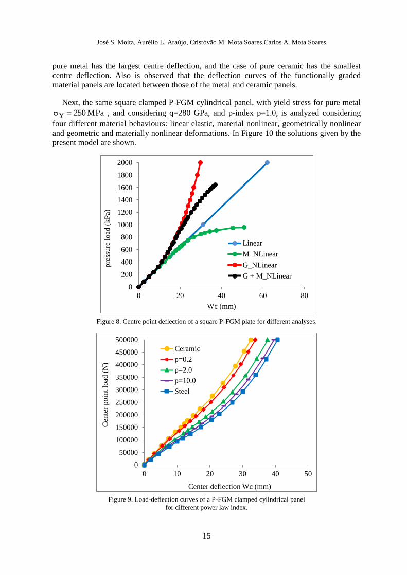
6.5 Simply Supported Square P- FGM Plate
A simply supported square (axa) with side dimension a=1.0 m and side to thickness ratio
a/h=50, is under a uniformly distributed load of intensity 2
0 m/N 1000q . The material
properties for the ceramic and metal constituents are Ec = 350 GPa, cν = 0.24, Em = 70 GPa,
mν = 0.30. The yield stress for pure metal is MPa 225Y , the ratio q/Ec is taken as 0.80,
based on the micro- indentation experiments by Gu et al. [17], and is considered q=290 GPa.
This P-FGM plate with p-index power-law function p=1.0, is analyzed considering four
different material behaviours: elastic deformation, materially nonlinear deformation,
geometrically nonlinear deformation and geometrically and material nonlinear deformation.
In Figure 8 the results obtained with the present model are shown, considering ten layers.
6.6 Geometrically nonlinear analysis of a clamped functionally graded cylindrical panel
A square clamped P-FGM cylindrical shell panel with constituents silicon nitride and
stainless steel, side-to-thickness ratio a/h=100, side-to-radius ratio a/R=0.1, and several
power law exponents p are presented. The material properties for the ceramic and metal
constituents are Ec = 322.27 GPa, cν = 0.24, Em = 207.78 GPa, mν = 0.3177. The panel is
modelled by a 12x12 finite element mesh (288 triangular elements), and considering ten
layers. Using the present model, Figure 9 shows the centre deflection due to a centre point
applied load P for the different power-law p-index considered, and as expected, the case of
0 0.5 1 1.5 2
0
2.5
5
7.5
10
12.5
15
17.5
20
W*
q*
Linear (PM) Linear [34 ]
G_NLinear (PM) G_NLinear [34 ]
M_NLinear (PM) M_NLinear [34 ]
G+M_NLinear (PM) G+M_NLinear [34 ]
José S. Moita, Aurélio L. Araújo, Cristóvão M. Mota Soares,Carlos A. Mota Soares
15
pure metal has the largest centre deflection, and the case of pure ceramic has the smallest
centre deflection. Also is observed that the deflection curves of the functionally graded
material panels are located between those of the metal and ceramic panels.
Next, the same square clamped P-FGM cylindrical panel, with yield stress for pure metal
MPa 250Y , and considering q=280 GPa, and p-index p=1.0, is analyzed considering
four different material behaviours: linear elastic, material nonlinear, geometrically nonlinear
and geometric and materially nonlinear deformations. In Figure 10 the solutions given by the
present model are shown.
Figure 8. Centre point deflection of a square P-FGM plate for different analyses.
Figure 9. Load-deflection curves of a P-FGM clamped cylindrical panel
for different power law index.
0
200
400
600
800
1000
1200
1400
1600
1800
2000
0 20 40 60 80
pre
ssure
load
(kP
a)
Wc (mm)
Linear
M_NLinear
G_NLinear
G + M_NLinear
0
50000
100000
150000
200000
250000
300000
350000
400000
450000
500000
0 10 20 30 40 50
Cen
ter
po
int
load
(N
)
Center deflection Wc (mm)
Ceramic
p=0.2
p=2.0
p=10.0
Steel

José S. Moita, Aurélio L. Araújo, Cristóvão M. Mota Soares,Carlos A. Mota Soares
16
Figure 10. Centre point deflection of a P-FGM clamped cylindrical panel for different analyses.
7 CONCLUSIONS
A finite element model for the static analysis of functionally graded material plate-shell
structures is extended for the material and geometrically nonlinear analysis. The model is
based on the Reddy’s third order shear deformation theory, implemented in a non-
conforming flat triangular plate/shell element with 24 degrees of freedom for the generalized
displacements. The continuous variation of the mechanical properties through the thickness is
approximated by only ten layers for all FGM applications, which preserves the reduced
computational time of the model.
From the results obtained by the present model, a very good accuracy is found with the
available comparing solutions obtained by alternative models. Two examples are also
proposed which can be used as benchmark tests for FGM plate-shell structures with material
and geometrically nonlinear behaviour.
ACKNOWLEDGEMENTS: This work was supported by FCT, Fundação para a Ciência e
Tecnologia, through IDMEC, under LAETA, project UID/EMS/50022/2013.
REFERENCES
[1] M. Koizumi, The concept of FGM Ceram. Trans. Funct. Grad. Mater., 34, 3–10, 1993.
[2] J.N. Reddy, C.D. Chin, Thermomechanical analysis of functionally cylinders and plates.
J. Thermal Stress. 21, 593–626, 1998.
[3] G.N. Praveen, J.N. Reddy, Nonlinear transient thermoelastic analysis of functionally
graded ceramic–metal plates. Int. J. Solids Struct., 35, 4457–4476, 1998.
[4] J.N. Reddy, Analysis of Functionally Graded Plates, International Journal for Numerical
Methods in Engineering, 58, 2177–2200, 2000.
[5] J. Woo, S.A. Meguid, Nonlinear analysis of functionally graded plates and shallow
shells. Int. J. Solids Struct., 38, 7409–7421, 2001.
0
50
100
150
200
250
300
350
400
450
500
0 10 20 30 40 50
Cen
tre
Po
int
Lo
ad (
kN
)
Centre deflection Wc (mm)
power law p-index=1.0
Linear
G_NLinear
M_NLinear
G+M_NLinear

José S. Moita, Aurélio L. Araújo, Cristóvão M. Mota Soares,Carlos A. Mota Soares
17
[6] J.Yang, H.S.Shen, Nonlinear bending analysis of shear deformable functionally graded
plates subjected to thermomechanical loads under various boundary conditions. Compos.
Part B: Eng., 34, 103–115, 2003.
[7] J. Yang, H.S. Shen, Nonlinear analysis of functionally graded plates under transverse
and in-plane loads. Int. J. Nonlinear Mech., 38 , 467–482, 2003.
[8] L.S. Ma, T.J. Wang, Nonlinear bending and postbuckling of functionally graded circular
plates under mechanical and thermal loadings. Int. J. Nonlinear Mech. 40, 3311–3330, 2003.
[9] K.S. Na, J.H. Kim, Nonlinear bending response of functionally graded plates under
thermal loads. J. Thermal Stress., 29, 245–261, 2005.
[10] J.N. Reddy, R.A. Arciniega, Mechanical and thermal buckling of functionally graded
ceramic–metal plates. In: Analysis and Design of Plated Structures: Stability. Woodhead
Publishing, Cambridge, UK, 2006.
[11] J.N. Reddy, R.A. Arciniega, Free vibration analysis of functionally graded plates. In:
Analysis and Design of Plated Structures: Dynamics. Woodhead Publishing, Cambridge, UK,
2006.
[12] R.A.Arciniega, J.N. Reddy, Large deformation analysis of functionally graded shells.
International Journal of Solids and Structures, 44, 2036–2052, 2007.
[13] K.D. Kim, G.R. Lomboy, S.C. Han, Geometrically nonlinear analysis of functionally
graded material (FGM) plates and shells using a four-node quasi-conforming shell element.
Journal of Composite Materials, 42, 5, 485-511, 2008.
[14] A.T. Barbosa, A.J.M. Ferreira, Geometrically nonlinear analysis of functionally graded
plates and shells. Mechanics of Advanced Materials and Structures, 17, 40–48, 2010.
[15] I. Tamura, Y. Tomota, H. Ozawa, Strength and ductility of Fe–Ni–C alloys composed
of austenite and martensite with various strength.Proceedings of the Third International
Conference on Strength of Metals and Alloys, vol. 1, Cambridge: Institute of Metals, 611–5,
1973.
[16] T. Nakamura, T. Wang, S. Sampath, Determination of properties of graded materials by
inverse analysis and instrumented indentation. Acta Mater., 48, 4293–306, 2000.
[17] Y. Gu, T. Nakamura, L. Prchlik, S. Sampath, J. Wallace, Micro-indentation and inverse
analysis to characterize elastic–plastic graded materials. Materials Science and Engineering
A, 345, 223–233, 2003.
[18] J.H.Jin, G .H. Paulino, R.H.Dodds Jr, Cohesive fracture modeling of elastic–plastic
crack growth in functionally graded materials. Eng Fract Mech, 70 (14), 1885–912, 2003.
[19]K. Swaminathan, D.T. Naveenkumar, A.M. Zenkour, E. Carrera. Stress, vibration and
buckling analyses of FGM plates: A state-of-the-art review. Composite Structures, 120, 10–
31, 2015.
[20] G.Bao, L. Wang. Multiple Cracking in Functionally Graded Ceramic/Metal Coatings,
International Journal of Solids and Structures, 32, 2853–2871, 1995.
[21] F. Delale, F. Erdogan, The crack problem for a nonhomogeneous plane, ASME Journal
of Applied Mechanics, 50, 609–614, 1983.
[22]Y.L. Chung, S.H. Chi, The residual stress of functionally graded materials, Journal of
Chinese Institute of Civil and Hydraulic Engineering, 13, 1–9, 2001.
[23]S.H.Chi, Y.L. Chung.Cracking in Sigmoid functionally graded coating, Journal of
Mechanics, 18, 41–53, 2002.
[24] J.N.Reddy. Mechanics of Laminated Composite Plates and Shells, 2 nd Edition, CRC
Press, 2004.

José S. Moita, Aurélio L. Araújo, Cristóvão M. Mota Soares,Carlos A. Mota Soares
18
[25] J.S. Moita, J.I.Barbosa, C.M. Mota Soares, C.A. Mota Soares, Sensitivity analysis and
optimal design of geometric nonlinear laminated plates and shells.Computers and Structures,
76, 407-420, 2000.
[26] E. Hinton, D.R.J Owen. Finite Element Software for Plates and Shells. Swansea, UK:
Pineridge Press, 1984.
[27] O.C. Zienkiewicz, The Finite Element Method. New York, USA: McGraw-Hill, 1977.
[28] K.J. Bathe, Finite Element Procedures in Engineering Analysis. Prentice-Hall Inc,
Englewood Cliffs, New Jersey, 1982.
[29]K.J. Bathe, L.W. Ho, A simple and effective element for analysis of general shell
structures. Computers and Structures, 13, 673-681, 1981.
[30]J.S. Moita, A.L. Araújo, P.G. Martins, C.M. Mota Soares, C.A. Mota Soares, Analysis of
active-passive plate structures using a simple and efficient finite element model. Mechanics
of Advanced Materials and Structures, 18, 159-169, 2011.
[31]J.S. Moita, C.M. Mota Soares, C.A. Mota Soares, Buckling behaviour of laminated
composite structures using a discrete higher-order displacement model. Composite
Structures 35, 75-92, 1996.
[32]M.A. Crisfield, A fast incremental/iterative solution procedure that handles snap-
through. Computers and Structures, 62, 13-55, 1980.
[33]Supriyomo, M.H. Aliabadi, M. H., Boundary element method for shear deformable plates
with combined geometric and material nonlinearities. Engineering Analysis with Boundary
Elements, 30, 31-42, 2006.
[34]L.Waidemam, Formulação do método dos elementos de contorno para placas enrigecidas
considerando-se não-linearidades física e geométrica. Tese de Doutorado, Universidade de S.
Paulo, Escola de Engenharia de S. Carlos, 2008 (In Portuguese).
http://www.teses.usp.br/teses/disponiveis/18/18134/tde-10092008-102729/en.php