material handling systems - iowa mold tooling co., inc. · material handling systems 20120920 iowa...
TRANSCRIPT

OPERATION : 99903422: PAGE - 1
CRANE SPECIFICATIONS &OPERATION MANUAL
MODELS 0.5/4, 1.5/10, 2.0/15T, 2.6/19T
IOWA MOLD TOOLING CO., INC.BOX 189, GARNER, IA 50438-0189
641-923-3711
MANUAL PART NO: 99903422
MATERIAL HANDLING SYSTEMS
20120920
Iowa Mold Tooling Co., Inc. is an Oshkosh Corporation Ccompany.

OPERATION : 99903422: PAGE - 2
TABLE OF CONTENTS
20020515
1.0 CRANE DESCRIPTION................................................................................................. 5MODEL 0.5/4 .................................................................................................................. 5MODEL 1.5/10, 2.0/15T, 2.6/19T ..................................................................................... 6
2.0 OPERATING INSTRUCTIONS ...................................................................................... 72.1 START UP ................................................................................................................ 72.1.1 STABILIZER SET-UP (IF APPLICABLE) .............................................................. 72.2.2 STARTING THE HYDRAULIC SYSTEM ............................................................... 82.3 FOLDING / UNFOLDING THE CRANE.................................................................... 82.4 SAFE DISTANCES TO ELECTRICAL WIRES ........................................................ 92.5 ATTACHING THE LOAD .......................................................................................... 92.6 LOADER REACH & CAPACITY............................................................................... 92.6.1 MODEL 0.5/4 CAPACITY CHART ....................................................................... 102.6.2 MODEL 1.5/10 CAPACITY CHART ..................................................................... 102.6.4 MODEL 2.0/15T CAPACITY CHART................................................................... 112.6.5 MODEL 2.6/19T CAPACITY CHART................................................................... 112.7 CRANE OPERATION ............................................................................................. 122.7.1 OPERATION - MODEL 0.5/4 ............................................................................... 122.7.2 OPERATION - MODELS 1.5/10, 2.0/15T & 2.6/19T ............................................ 12
4.0 HYDRAULIC SAFETY SYSTEM ................................................................................. 134.1 MODEL 1.5/10, 2.0/15T, 2.6/19T HYDRAULIC SAFETY SYSTEM ........................ 134.3 MODEL 1.5/10 ELECTRO-HYDRAULIC DIAGRAM .............................................. 144.3.2 MODEL 1.5/10 HYDRAULIC DIAGRAM.............................................................. 154.3.3 MODEL 2.0/15T ELECTRO-HYDRAULIC DIAGRAM ......................................... 164.3.4 MODEL 2.0/15T HYDRAULIC DIAGRAM ........................................................... 174.3.5 MODEL 2.6/19T ELECTRO-HYDRAULIC DIAGRAM ......................................... 184.3.6 MODEL 2.6/19T HYDRAULIC DIAGRAM ........................................................... 19
5.0 MAINTENANCE ........................................................................................................... 205.1 MODEL 0.5/4 - DAILY MAINTENANCE POINTS ................................................... 205.2 MODEL 1.5/10, 2.0/15T, 2.6/19T - DAILY MAINTENANCE POINTS ...................... 21
6.0 LUBRICATION & OIL CHANGE .................................................................................. 226.1 MODEL 1.5/10, 2.0/15T, 2.6/19T GREASE ZERK LOCATIONS ............................ 226.3 CHANGING THE OIL AND OIL FILTER ................................................................. 236.3.1 MODEL 1.5/10, 2.0/15T, 2.6/19T - CHANGING THE OIL & OIL FILTER BY THE
ELECTRIC POWER PACK..................................................................................... 236.3.2 MODEL 1.5/10, 2.0/15T, 2.6/19T - CHANGING THE OIL & OIL FILTER BY PTO-
HYDRAULIC ........................................................................................................... 236.3.4 HYDRAULIC OIL & GREASE SPECIFICATIONS............................................... 24
7.0 BLEEDING AIR FROM CYLINDERS .......................................................................... 257.1 MODEL 1.5/10, 2.0/15T, 2.6/19T ............................................................................. 257.3 ACCESSORIES (MODELS 1.5/10, 2.0/15T, 2.6/19T ONLY) ................................... 26
8.0 CHANGE OF SLEWING AREA ................................................................................... 278.1 MODEL 1.5/10, 2.0/15T, 2.6/19T CHANGE OF SLEWING AREA .......................... 27
9.0 TECHNICAL DATA ...................................................................................................... 289.1A MODEL 0.5/4 DIMENSIONAL DRAWINGS ......................................................... 289.1B MODEL 0.5/4 TECHNICAL DATA ....................................................................... 29

OPERATION : 99903422: PAGE - 320020515
9.2A MODEL 1.5/10 T1 (T2) DIMENSIONAL DRAWINGS ........................................... 309.2B MODEL 1.5/10 T1 M (T2 M) DIMENSIONAL DRAWINGS ................................... 319.2C MODEL 1.5/10 TECHNICAL DATA ..................................................................... 329.2D POWER CONSUMPTION / PUMP PERFORMANCE ......................................... 329.4A: DIMENSIONAL DRAWING, 2.0/15T.................................................................... 339.4B: DIMENSIONAL DRAWING, 2.0/15T STATIONARY MOUNT .............................. 349.4C: 2.0/15T TECHNICAL DATA................................................................................ 359.5A: DIMENSIONAL DRAWING, 2.6/19T.................................................................... 369.5B: 2.6/19T TECHNICAL DATA................................................................................ 37
11.0 REPAIR ...................................................................................................................... 38
TABLE OF CONTENTS, CONTINUED

OPERATION : 99903422: PAGE - 4
In addition to the information presented in thismanual, read and understand the IMT Crane
Operator's Safety Manual before operating orperforming any maintenance on your crane.
DATE LOCATION DESCRIPTION OF CHANGE
REVISIONS LIST
20030611 11 REVISED CAPACITY PLACARD TO INCLUDE MANUAL EXTENSION NOTE20070228 COVER UPDATED OWNERSHIP STATEMENT20091120 ADDED MODEL 2.0/15T20100414 ADDED MODEL 2.6/19T20111129 ECN 11628 - UPDATED STABILIZER VERBIAGE, ELEC. DISTANCES20120920 REMOVED OBSOLETE MODEL 1.7/20

OPERATION : 99903422: PAGE - 5
1.0 CRANE DESCRIPTION
MODEL 0.5/41. BASE2. MAST3. LOWER BOOM4. EXTENSION BOOM5. HINGE PIN6. CYLINDER BOLT7. EXTENSION PIN8. LOWER BOOM CYLINDER9. ROTATION / SLEWING CRANK10. HAND PUMP11. PUMP LEVER12. HOOK
20020515

OPERATION : 99903422: PAGE - 6
MODEL 1.5/10, 2.0/15T, 2.6/19T1. BASE2. ROTATION / SLEWING CYLINDER3. MECHANICAL STABILIZER LEG4. STABILIZER BEAM5. MAST6. LOWER BOOM CYLIINDER7. HINGE PIN8. LOWER BOOM9. EXTENSION CYLINDER10. 1st EXTENSION BOOM, 100 MM (1.5/10) or 120 MM (2.0/15T or 2.6/19T)11. 2nd EXTENSION BOOM, 83 MM (1.5/10) or 100 MM (2.0/15T or 2.6/19T)12. HOOK13. CONTROL VALVE BLOCK14. MOUNTING HARDWARE
20111129

OPERATION : 99903422: PAGE - 7
2.0 OPERATING INSTRUCTIONS
2.1 START UP
Before operatingthe loader:- Set vehicle parking brake.- Check oil levels in the tank and power pack.- Check hoses for damage, twists, or kinks.- Check all hooks, slings, and chains, if applicable.- Check that manual extensions are correctly fas-tened with lock bolts and split pins, if applicable.- DO NOT exceed the maximum load on manualextensions, if applicable.
2.1.1 STABILIZER SET-UP (IFAPPLICABLE)
CAUTIONNEVER OPERATE THE LOADER IF THE
STABILIZERS ARE NOT LOWERED!
For proper operation, the stabilizer legs should belowered just enough to raise the truck chassissuspension slightly. The truck, including the crane,should be parked on even ground to give a nearlyperfect slew of the crane.
If the job is on soft ground, put wooden blocks or steelplates under the stabilizer legs to ensure stability.(On Model 1.5/10, the weight on the stabilizer leg canexceed 1.3 tons.)
To set-up the stabilizer leg, release the stabilizer lockand extend the stabilizer beam completely. Then, re-lock it.
If the loader is equipped with swing-up stabilizer legs,they must be vertically locked.
20020515

OPERATION : 99903422: PAGE - 8
2.2.2 STARTING THE HYDRAULICSYSTEMStart the engine, disengage the clutch, and engage thePTO by pulling the handle located in the truck cab.
2.3 FOLDING / UNFOLDING THE CRANEAfter the stabilizer leg has been lowered (if applicable),unfold the boom as shown.
NOTENEVER STAND UNDER A CRANEWHEN IT IS BEING UNFOLDED.
NEVER START UNFOLDING DURINGA SLEWING MOVEMENT.
20120920
UNFOLDING MODEL 0.5/4, 1.5/10, 2.0/15T, 2.6/10T

OPERATION : 99903422: PAGE - 9
2.4 SAFE DISTANCES TO ELECTRICALWIRES
NORMAL VOLTAGE MINIMUM REQUIREDkV (Phase to Phase) CLEARANCE Feet (meters)
OPERATION NEAR From 0 to 350 20 ( 6.10)HIGH VOLTAGE Over 350 or unknown 50 (15.24)
OPERATION IN From 0 to 0.75 4 ( 0.22)TRANSIT WITH From 0.75 to 50 6 ( 0.83)NO LOAD AND From 50 to 345 10 ( 3.05)BOOM OR MAST From 345 to 750 16 ( 4.87)LOWERED. From 750 to 1000 20 ( 8.10)
2.5 ATTACHING THE LOADAttach the load and auxiliary equipment securely and carefully to the hook directly or by use of straps or chains.
2.6 LOADER REACH & CAPACITYFigures for reach and capacity are shown on the capacity charts on the following pages. Your crane is designedfor specific loads which are defined on the capacity placard which is mounted near the operator’s station and onthe crane. Exceeding the limits presented on the capacity placard will create severe safety hazards and willshorten the life ot the crane. The operator and other concerned personnel must know the load capacity of thecrane and the weight of the load being lifted!
WARNINGNEVER EXCEED THE CRANE’S RATED LOAD CAPACITIES. DOING SO WILL CAUSE STRUCTURALDAMAGE AND DAMAGE TO WINCHES AND CABLES WHICH CAN LEAD TO SERIOUS INJURIES OR
DEATH.
NOTELOAD LIMIT INFORMATION ON THE CAPACITY PLACARD IS FORMULATED ON 85% OF TIPPING.
“TIPPING” REFERS TO THE CRANE ACTUALLY TIPPING WITH ITS OPPOSITE STABILIZER AND TIRESHAVING BROKEN CONTACT WITH THE SURFACE.
Prior to lifting a load:1. Determine the weight of the load.2. Determine the weight of any load handling devices.3. Add the weight of the load and the weight of the load handling devices. The sum will be the total weight ofthe load being lifted.4. Determine the distance from the centerline of crane rotation to the centerline of the load being lifted.5. Determine the distance from the centerline of crane rotation to the centerline of where the location to whichthe load is to be moved.6. The actual distance used should be figured as the larger of items 4 and 5 above.7. Determine at what angle the crane will be operated (for example 30°, 45°, etc.) by referencing the angleindicator on the lower boom.8. Make certain that 2-part line is used for any lift which requires 2-part line.
20120920

OPERATION : 99903422: PAGE - 10
2.6.1 MODEL 0.5/4 CAPACITY CHART
2.6.2 MODEL 1.5/10 CAPACITY CHART
Model 0.5 / 4
0CENTERLINE�
2’-0"(0.61m)
3’-9"(1.15m)
6’-6"(2.00m)
8’-0"(2.44m)
0MOUNTINGSURFACE
2’-0"(0.61m)
4’-0"(1.22m)
70396145
Working loads will be limited to those shown. Deduct the weight of load handling devices.
Before lift is made, stabilitymust be checked perSAE J765A.
5’-0"(1.52m)
70396146
0CENTERLINE
3’-0"(0.91m)
4’-1"(1.25m)
6’-11"(2.10m)
12’-0"(3.66m)
9’-8"(2.95m)
-3’-0"(0.91m)
0MOUNTINGSURFACE
-3’-0"(-0.91m)
3’-0"(0.91m)
6’-0"(1.83m)
Model 1.5 / 10
Working loads will be limited to those shown. Deduct the weight of load handling devices.
Before lift is made, check stability per SAE J765A.
20120920

OPERATION : 99903422: PAGE - 11
2.6.4 MODEL 2.0/15T CAPACITY CHART
20091120
70398855
Model 2.0/15T Limit working loads to those
dispositivos de manipulaci�n de cargas es parte de la carga levantada y se debe descontar de la capacidad nominal.
shown. Deduct the weightof load handling devices.
El peso propio (tara) de los
0
0SURFACEMOUNTING
CENTERLINE3’
(.91m)6’
(1.83m)9’
(2.74m)12’
(3.67m)
3’(0.91m)
6’(1.83m)
36801670
1985900
1325600
2.6.5 MODEL 2.6/19T CAPACITY CHART
70398904
Model 2.6/19T Limit working loads to those
dispositivos de manipulaci�n de cargas es parte de la carga levantada y se debe descontar de la capacidad nominal.
shown. Deduct the weightof load handling devices.
El peso propio (tara) de los
38801760
22701030
1610730
0
0SURFACEMOUNTING
CENTERLINE3’
(.91m)6’
(1.83m)9’
(2.74m)12’
(3.67m)
6’(1.83m)lb
kg

OPERATION : 99903422: PAGE - 12
2.7 CRANE OPERATION
2.7.1 OPERATION - MODEL 0.5/4Crane model 0.5/4 is operated using pumps andcranks. The lifting and lowering functions of the craneare operated using a hand pump with a needle valve,and the crane slew is operated by turning a crank. Anoptional power unit is available instead of the handpump for lifting, if ordered with the crane.
2.7.2 OPERATION - MODELS 1.5/10,2.0/15T & 2.6/19TThese crane models are operated using controlvalves. Move the control valves gently, especiallywhen working with heavy loads. The working speed ofthe crane is controlled using the valves. Jerky controlvalve operation causes the load to swing and moveuncontrollably and put unnecessary strain on thecrane.
NOTEALWAYS OPERATE CONTROL LEVERS
GENTLY AND STEADILY.
20020515

OPERATION : 99903422: PAGE - 13
4.0 HYDRAULIC SAFETY SYSTEMNOTE: Model 0.5/4 has manual extensions andcontrols, so this section does not apply to that model.
4.1 MODEL 1.5/10, 2.0/15T, 2.6/19THYDRAULIC SAFETY SYSTEM
1) Control ValveMain relief valve- Safeguard in case of overload.
2) Rotation/Slewing CylinderDouble port-relief valve- Safeguard in case of overload.
3) Lower Boom CylinderSingle-acting load-holding valve- Safeguard in case of hose failure/ overload- Keeps the boom in position by relieving pressure
on pipes and hoses
4) Stabilizer CylinderPiloted check valve- Safeguard in case of hose failure / overload
5) Extension CylinderDouble-acting, load-holding valve- Safeguard in case of hose failure / overload- Keeps the boom in position by relieving pressure
on pipes and hoses
20111129
OPERATION : 99903422: PAGE - 14
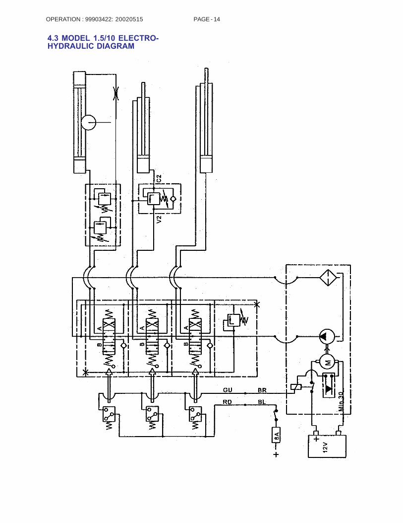
4.3 MODEL 1.5/10 ELECTRO-HYDRAULIC DIAGRAM
20020515

OPERATION : 99903422: PAGE - 15
4.3.2 MODEL 1.5/10 HYDRAULICDIAGRAM
20020515
OPERATION : 99903422: PAGE - 16
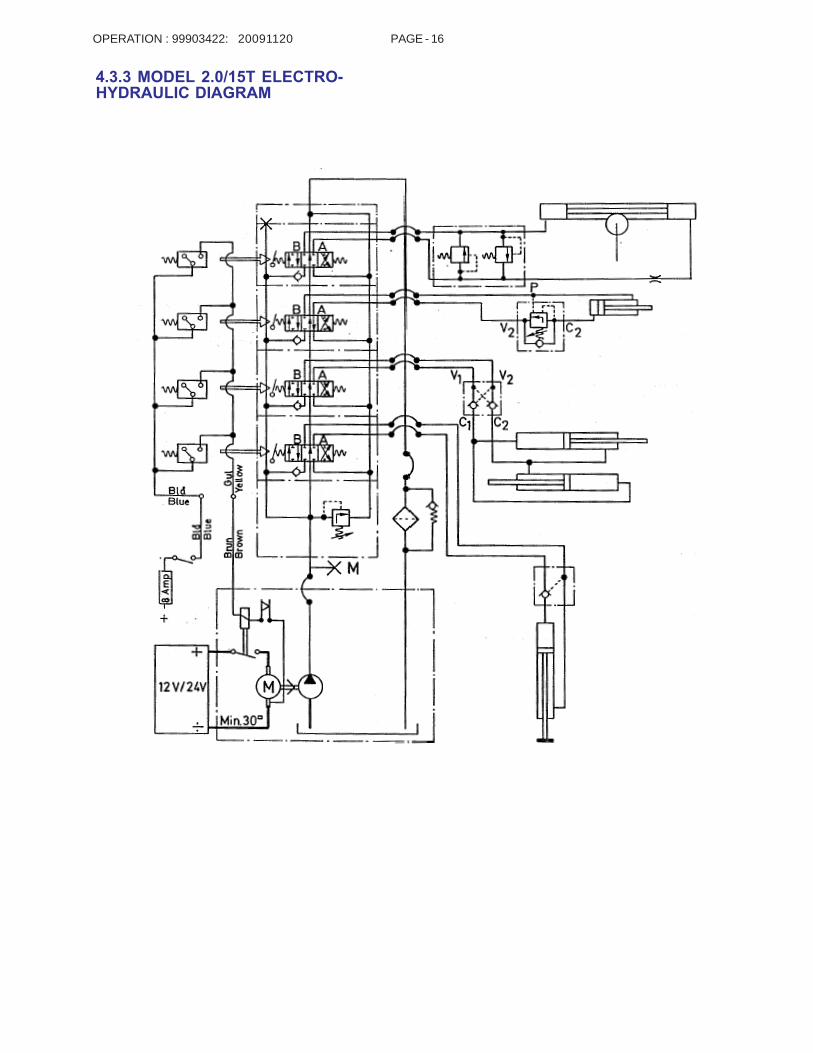
4.3.3 MODEL 2.0/15T ELECTRO-HYDRAULIC DIAGRAM
20091120

OPERATION : 99903422: PAGE - 17
4.3.4 MODEL 2.0/15T HYDRAULICDIAGRAM
20091120

OPERATION : 99903422: PAGE - 18
4.3.5 MODEL 2.6/19T ELECTRO-HYDRAULIC DIAGRAM
20100414

OPERATION : 99903422: PAGE - 19
4.3.6 MODEL 2.6/19T HYDRAULICDIAGRAM
20100414

OPERATION : 99903422: PAGE - 20
5.0 MAINTENANCE
5.1 MODEL 0.5/4 - DAILYMAINTENANCE POINTS
Check pins, splits, etc.
Tighten bolts if necessary.
Lubricate with oil can.
- Replenish the tank (base) if needed.- Check hoses for damage and leaks.
20020515

OPERATION : 99903422: PAGE - 21
5.2 MODEL 1.5/10, 2.0/15T, 2.6/19T- DAILY MAINTENANCE POINTS- Check the oil level in the base.
- Periodically check hoses and pipes for damageand leaks.
Check pins, splits, etc.
Tighten bolts if necessary.
20020515

OPERATION : 99903422: PAGE - 22
6.0 LUBRICATION & OIL CHANGEThe crane should be lubricatedt horoughly at thesame intervals as the truck. However, in case ofintensive use, it should be lubricated weekly. If thecrane is used continuously, it should be lubricateddaily.
NOTE:Check the oil level in the base periodically.
KEY - GREASE ZERK CHARTS
Fill with oil at these locations.
Grease zerk locations.
Apply grease with a spatula.
Apply grease with a brush.6.1 MODEL 1.5/10, 2.0/15T, 2.6/19TGREASE ZERK LOCATIONS
NOTES:
Change oil and oil filter on an annualbasis.
Keep water and impurities from the oiltank.
If necessary, refill the oil tank afterbleeding air from the system.
Do not mix different brands of oil.
20120920

OPERATION : 99903422: PAGE - 23
6.3 CHANGING THE OIL AND OILFILTER
6.3.1 MODEL 1.5/10, 2.0/15T, 2.6/19T -CHANGING THE OIL & OIL FILTER BYTHE ELECTRIC POWER PACK
1. Fold the crane completely.
2. Remove the air filter (1), and empty the oil tank.
3. Dismantle the nut (3) in the end plate of the oiltank, remove the tank, and change the oil filter (2) ifnecessary.
4. Mount the tank and fill it with oil.
NOTE: Fill the tank with 2.11 gallons (8 l) of oil, even ifthe base is not used as a tank.
6.3.2 MODEL 1.5/10, 2.0/15T, 2.6/19T -CHANGING THE OIL & OIL FILTER BYPTO-HYDRAULIC
1. Remove the air filter (1) and the drain plug. Emptythe oil tank.
2. Change the oil filter (2).
3. Mount the drain plug. Fill the tank with oil.
4. Mount the air filter (1).
20091120

OPERATION : 99903422: PAGE - 24
6.3.4 HYDRAULIC OIL & GREASESPECIFICATIONS
Choose hydraulic oils and greases using the tablesbelow as guides. If the loader will be working below32° F (0° C), select an oil designed for low tempera-tures, which has a higher viscosity index. Oil typesnot specified on the charts may be used if theycorrespond to the quality and specifications indicated.
In the winter, 1% isopropyl alcohol may be added tothe oil to avoid condensed water problems.
During extreme temperatures, -40° F / + 167 °F (-40°C / +75° C), select hydraulic oil such as Esso UnivisJ26 or another comparable brand.
Grease telescopic jibs with Esso ESL 454. Applygrease where the telescopic jibs contact the slideblocks.
HYDRAULIC OIL SPECIFICATIONS AND APPLICATION POINTS
LUBRICANT SPECIFICATIONS
20020515
AMBIENT TEMPERATURE RANGE 0 - 90° BELOW 0° ABOVE 90°Minimum Pour Point, °F -40° -40° -10°Maximum Viscosity, SSU @ 0°F 5000 1500 ---Minimum Viscosity, SSU @ 100°F 140-195 80-90 200-335Minimum Viscosity, SSU @ 210°F 48 39 49Minimum Viscosity Index 139 139 95ISO VG Grade 32 15 46Mobil Oils (Reference) DTE 13M DTE 11M DTE 25
APPLICATION POINT LUBRICATION PRODUCT APPLICATION MEANS INTERVALPinion and Drive Gear Shell Alvania 2EPRotation Brake ORWinch Brake Shell Retinax “A” Hand Grease Gun WeeklyWinch Sheave OR ORTurntable Bearing Mobilith AW2 Pneumatic PressureCylinder Pins OR GunBoom Hinge Pins EquivalentBoom Rollers
Rotation Worm Gear Molub-Alloy 936 or Equiv. Brush On Weekly
PTO Transmission Mobilube HD 80W90 Fill to Check MonthlyWinch Sump Plug
OPERATION : 99903422: PAGE - 25
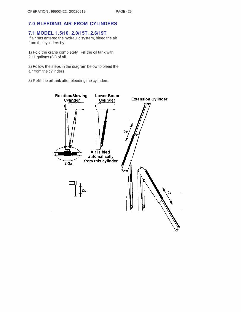
7.0 BLEEDING AIR FROM CYLINDERS
7.1 MODEL 1.5/10, 2.0/15T, 2.6/19TIf air has entered the hydraulic system, bleed the airfrom the cylinders by:
1) Fold the crane completely. Fill the oil tank with2.11 gallons (8 l) of oil.
2) Follow the steps in the diagram below to bleed theair from the cylinders.
3) Refill the oil tank after bleeding the cylinders.
20020515

OPERATION : 99903422: PAGE - 2620120920
7.3 ACCESSORIES (MODELS 1.5/10,2.0/15T, 2.6/19T ONLY)
MANUAL EXTENSIONS
An extra jib extension can be supplied for the loader.The manual extension is adapted especially for theparticular type of loader. It should not be shortened orlengthened.
Use only factory original manual extensions.

OPERATION : 99903422: PAGE - 2720091120
8.0 CHANGE OF SLEWING AREA
8.1 MODEL 1.5/10, 2.0/15T, 2.6/19TCHANGE OF SLEWING AREA1) Position the crane so that the slew to both sides isexactly the same (neutral position).
2) Remove oil from the base using the drain plug (5).
3) Remove the slewing cylinder (1).
4) Pull out the slide block (4) using the M8 threadedhole.
5) Pull out the rack (3).
6) Manually turn the loader column to the required “C”(Figure 2).
7) Place the rack (3) in the slewing house. Thedistance between the outer part of the rack (3) andthe end plate must be approximately 2.8” ± .3” (71.5mm ± 8 mm), depending on the mutual mesh of theteeth.
8) Place the slide block (4) behind the rack (3).Remount the slewing cylinder (1).
9) Lubricate the bolts (2) with Locktite Normal orLocktite No. 242. Screw the bolts back in.
10) Replace the drain plug (5). Replace oil if needed.

OPERATION : 99903422: PAGE - 28
9.0 TECHNICAL DATA
9.1A MODEL 0.5/4 DIMENSIONAL DRAWINGS
20020515
OPERATION : 99903422: PAGE - 29
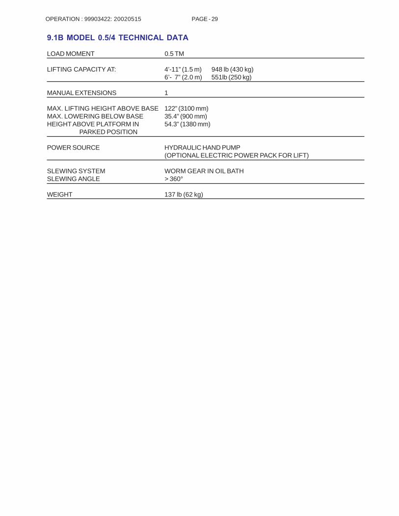
9.1B MODEL 0.5/4 TECHNICAL DATA
LOAD MOMENT 0.5 TM
LIFTING CAPACITY AT: 4’-11” (1.5 m) 948 lb (430 kg)6’- 7” (2.0 m) 551lb (250 kg)
MANUAL EXTENSIONS 1
MAX. LIFTING HEIGHT ABOVE BASE 122” (3100 mm)MAX. LOWERING BELOW BASE 35.4” (900 mm)HEIGHT ABOVE PLATFORM IN 54.3” (1380 mm)
PARKED POSITION
POWER SOURCE HYDRAULIC HAND PUMP(OPTIONAL ELECTRIC POWER PACK FOR LIFT)
SLEWING SYSTEM WORM GEAR IN OIL BATHSLEWING ANGLE > 360°
WEIGHT 137 lb (62 kg)
20020515

OPERATION : 99903422: PAGE - 30
9.2A MODEL 1.5/10 T1 (T2)DIMENSIONAL DRAWINGS
20020515
OPERATION : 99903422: PAGE - 31
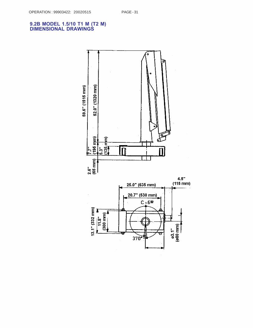
9.2B MODEL 1.5/10 T1 M (T2 M)DIMENSIONAL DRAWINGS
20020515

OPERATION : 99903422: PAGE - 32
9.2C MODEL 1.5/10 TECHNICAL DATAT1 T2 T1 M T2 M
LOAD MOMENT 1.5 tm 1.5 tm 1.5 tm 1.5 tmHYDRAULIC REACH 6-’11” (2.1 m) 9’-8” (2.95 m) 6-’11” (2.1 m) 9’-8” (2.95 m)SLEWING TORQUE 1013 ft-lb 1013 ft-lb 1013 ft-lb 1013 ft-lb
(140 kgm) (140 kgm) (140 kgm) (140 kgm)HEIGHT ABOVE CHASSIS 61.6” 61.6” 59.6” 59.6”WHEN FOLDED (1565 mm) (1565 mm) (1515 mm) (1515 mm)WIDTH WHEN FOLDED 20.5” 20.5” 20.5” 20.5”
(520 mm) (520 mm) (520 mm) (520 mm)STABILIZER SPREAD, 13.8” 13.8” -- --EXTENSION (350 mm) (350 mm)WEIGHT, LOADER INCL. 407.9 lb 440.9 lb -- --STABILIZER LEG & (185 kg) (200 kg)POWER PACKWEIGHT, LOADER EXCL. -- -- 352.7 lb 385.8 lbSTABILIZER LEG & (160 kg) (175 kg)POWER PACKOIL IN BASE 17.6 lb (8 kg) 17.6 lb (8 kg) 17.6 lb (8 kg) 17.6 lb (8 kg)OIL IN CYLINDERS & 8.8 lb (4 kg) 8.8 lb (4 kg) 8.8 lb (4 kg) 8.8 lb (4 kg)HOSES
9.2D POWER CONSUMPTION / PUMP PERFORMANCEALL MODELS
WORKING PRESSURE 2248 psi(15.5 MPa)
PUMP PERFORMANCE 1.06-2.11 gpm(4 - 8 l/min)
MAX. POWER CONSUMPTION 12 volt: 155 Amp 24 volt: 80 AmpBATTERY CAPACITY 12 volt: 120 Ah 24 volt: 80 AhOIL CAPACITY IN BASE 2.11 gal
(8 l)
20111129

OPERATION : 99903422: PAGE - 33
9.4A: DIMENSIONAL DRAWING, 2.0/15T
20091119
6’-1
" (1
850)
5’-2
" (1
565)
10.6"
9" MAX. 10’-6"(3200)
3’-11"(1200)
5’-1"(1560)
6"
(270)
(230)
22" (560)
13"(330)
(150)8"(205)
16"(410)
5’-6
" (1
680)
4’-1
1" (
1515
)
4.7"(120)
2.8"(70)
17"(435)
24"(610)
3"(80)
16"(400)
16/22"(405/560)
5’-3" (1600)
14"(350)
7"(170)
14"(360)
Dimensionsshown infeet-inches(mm).

OPERATION : 99903422: PAGE - 34
9.4B: DIMENSIONAL DRAWING, 2.0/15T STATIONARY MOUNT
20091119
4’-1
0" (
1470
)
5’-6
" (1
670)
8"(200)
Dimensionsshown infeet-inches(mm).
7"(180)
2’-6" (766)
1’-4" (400)
3.1"
(80
)
1’-4"(400)
8 3/4" (17)

OPERATION : 99903422: PAGE - 35
9.4C: 2.0/15T TECHNICAL DATA
20111129
2.0/15T 2-HYDRAULIC 2-HYDRAULIC STATIONARY-MOUNTCrane Rating* 14,465 ft-lb (2.0 tm) 14,465 ft-lb (2.0 tm)Maximum Horizontal Reach 10' 6" (3.2 m) 10' 6" (3.2 m)Maximum Vertical Reach 15' 9" (4.8 m) 15' 9" (4.8 m)Maximum Capacity 3680 lb (1670 kg) 3680 lb (1670 kg)Max Cap @ Max Reach 1325 lb (600 kg) 1325 lb (600 kg)Crane Weight, incl. stabilizer 530 lb (240 kg) and power packCrane Weight, exluding 660 lb (300 kg) power packCenter of Gravity - Stored Vertical 16" (405 mm) Horizontal (C/L RotTo Bridge) 4" (100 mm)Stabilizer Pad Diameter 6" (160 mm) 6" (160 mm)Crane Storage Height 5' 6" (1680 mm) 5' 6" (1670 mm)Mounting Space 1' 10" (560 mm) 1' 10" (560 mm)Rotational Torque 1375 ft lb (190 kg-m) 1375 ft lb (190 kg-m)Rotation 365 degrees 365 degreesOptimum Pump Performance 1.6 - 2.1 gpm (6-8 L/min) 1.6 - 2.1 gpm (6-8 L/min)System Pressure 2610 psi (180 bar) 2610 psi (180 bar)Oil Capacity in Base 1.7 gal (6.5 L) 1.7 gal (6.5 L)Stabilizers Extension 2'-0" (610 mm) -- Weight 440 lb (200 kg) --
PRESSURE SETTINGSUse a pressure gauge when setting pressures. Check pressure with annual inspection and after all majorrepairs.
WORKING PRESURE ON PORT-RELIEF VALVEMain relief valve 2610 psi (180 bar) 2610 psi (180 bar)Rotation (slewing) system 1815 psi (125 bar) 1815 psi (125 bar)
OPENING PRESURE ON LOAD-HOLDING VALVESBoom cylinder 2755 psi (190 bar) 2755 psi (190 bar)
PRESURE SETTINGS90% load 2320 psi (160 bar) 2320 psi (160 bar)100% load 2610 psi (180 bar) 2610 psi (180 bar)
PRESSURE SETTINGS FOR LOAD-MOMENT LIMITATIONSet the working pressure of the load-moment limitation to 145 psi (10 bar) less than the opening pressure of theload-holding valves of the boom cylinder. Thus, the setting is 2610 psi (180 bar).
* Crane rating (ft-lb) is the rated load (lb) multiplied by the respective distance (ft) from centerline of rotation withall extensions retracted and the inner and outer booms in a horizontal position, per ANSI B30.22.

OPERATION : 99903422: PAGE - 36
9.5A: DIMENSIONAL DRAWING, 2.6/19T
20100414
5’-9
" (1
750)
5’-4
" (1
645)
4’-8
" (1
425)
6.5"(165)
7"(180)
8.5"(215)
4’-11" MAX 11’-6" (1500 MAX 3500)
6.5"(165)
1’-5"(437)
9"(231)
2’-6" (770)3’-9" (1135) 1’-3"
(385)6.5"(165)
5’-0
" (1
520)
4’-5
" (1
350)
4.7"(120)
11.3"(286)
2’-10"(875)
15.7"(400)
16"/22"(405/560)
2.8"(70)
5’-7" (1695)
8.8" (223) 5.6" (143)
15"(385)

OPERATION : 99903422: PAGE - 37
9.5B: 2.6/19T TECHNICAL DATA
20111129
2.6/19T 2-HYDRAULICCrane Rating* 18,806 ft-lb (2.6 tm)Maximum Horizontal Reach 11' 6" (3.5 m)Maximum Vertical Reach 16' 1" (4.9 m)Maximum Capacity 3880 lb (1760 kg)Max Cap @ Max Reach 1610 lb (730 kg)Crane Weight 605 lb (275 kg)Center of Gravity - Stored Vertical 15" (380 mm) Horizontal (C/L RotTo Bridge) 12" (310 mm)Stabilizer Pad Diameter 5.5" (140 mm)Crane Storage Height 5' 0" (1520 mm)Mounting Space 1' 7" (475 mm)Rotational Torque 2460 ft lb (340 kg-m)Rotation 360 degreesOptimum Pump Performance 3.2 gpm (12 L/min)System Pressure 2683 psi (185 bar)Oil Capacity in Base 2.8 gal (10.5 L)Stabilizers Extension 2'-10" (875 mm) Weight 62 lb (28 kg)
PRESSURE SETTINGS (Continue from here)Use a pressure gauge when setting pressures. Check pressure with annual inspection and after all majorrepairs.
WORKING PRESURE ON MAIN-RELIEF VALVES AND PORT-RELIEF VALVEMain relief valve A & B-ports 2683 psi (185 bar)Stabilizer legs, grab, rotator Up & Down 2540 psi (175 bar)Extension cylinders Extend (B-port) 1815 psi (125 bar)
Retract (A-port) PBoom cylinder Down (B-port) 1815 psi (125 bar)
Up (A-port) 2683 psi (185 bar)Rotation system Right (B-port) 1450 psi (100 bar)
Left (A-port) 1450 psi (100 bar)
OPENING PRESURE ON LOAD-HOLDING VALVESBoom cylinder 2830 psi (195 bar)Extension cylinders 3625 psi (250 bar)
PRESURE SETTINGS FOR LOAD-MOMENT LIMITATION + 100% load 2685 psi (185 bar)PRESURE SETTINGS FOR LOAD-MOMENT LIMITATION + 90% load 2395 psi (165 bar)
* Crane rating (ft-lb) is the rated load (lb) multiplied by the respective distance (ft) from centerline of rotation withall extensions retracted and the inner and outer booms in a horizontal position, per ANSI B30.22.

OPERATION : 99903422: PAGE - 38
11.0 REPAIRIf your crane needs repair, always use an authorizedIMT dealer.
When ordering spare parts, know the:
Crane Model i.e. Model 1.5/10
Serial Number i.e. 421397
Reference number of the spare part required.
If you do not have a spare parts manual, contact yourdealer to order one.
20020515

OPERATION : 99903422: PAGE - 39

OPERATION : 99903422: PAGE - 40
IOWA MOLD TOOLING CO., INC.BOX 189, GARNER, IA 50438-0189
641-923-3711TECHNICAL SUPPORT FAX: 641-923-2424
20020515