material requirements for steel and composite...
TRANSCRIPT

Material Requirements for Steel and Composite Structures
Chiew Sing-PingSchool of Civil and Environmental EngineeringNanyang Technological University, SINGAPORE
22 January 2015

2
Scope
Higher Strength Materials Concrete (fck ≥ 50 MPa) Reinforcing steel (fsk ≥ 500 MPa) Structural steel (fyk ≥ 460 MPa)
Seismic Requirements (BC3: 2013) Materials for seismic design Detailing for seismic design
3
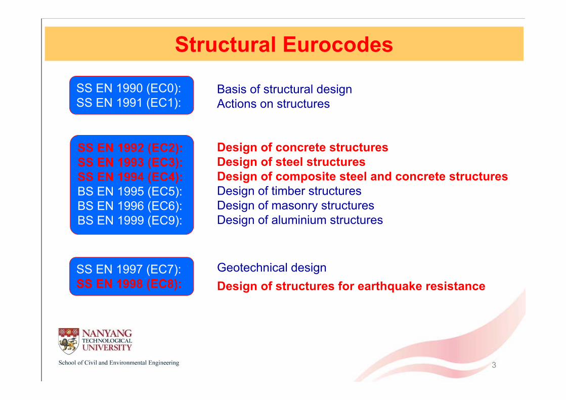
Structural Eurocodes
SS EN 1990 (EC0):SS EN 1991 (EC1):
Basis of structural designActions on structures
Design of concrete structuresDesign of steel structuresDesign of composite steel and concrete structuresDesign of timber structuresDesign of masonry structuresDesign of aluminium structures
Geotechnical designDesign of structures for earthquake resistance
SS EN 1992 (EC2):SS EN 1993 (EC3):SS EN 1994 (EC4):BS EN 1995 (EC5):BS EN 1996 (EC6):BS EN 1999 (EC9):
SS EN 1997 (EC7):SS EN 1998 (EC8):
4
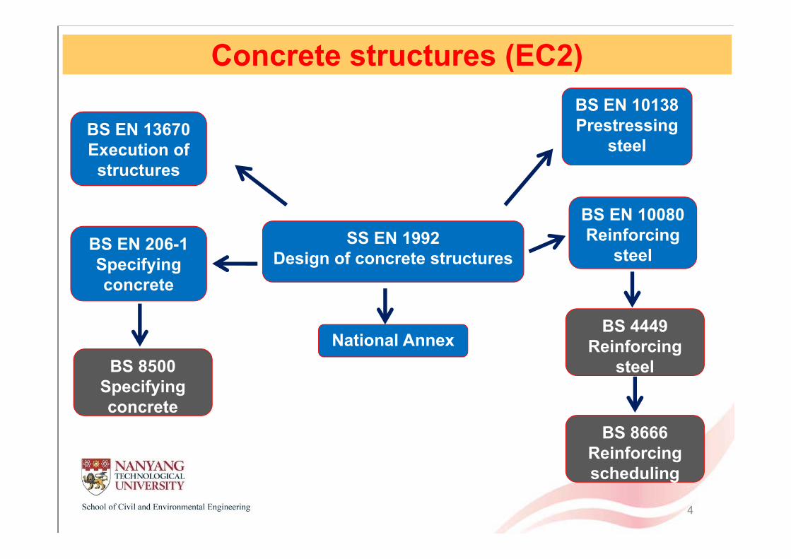
SS EN 1992Design of concrete structures
BS EN 206-1Specifying concrete
BS EN 10080Reinforcing
steel
BS EN 13670Execution of structures
BS EN 10138Prestressing
steel
National Annex BS 8500
Specifying concrete
BS 4449Reinforcing
steel
BS 8666Reinforcing scheduling
Concrete structures (EC2)

5
Concrete
Six density classes of lightweight concrete are defined in EN206-1.Density class 1.0 1.2 1.4 1.6 1.8 2.0Density (kg/m3) 801-
10001001-1200
1201-1400
1401-1600
1601-1800
1801-2000
Density (kg/m3)
Plain concrete 1050 1250 1450 1650 1850 2050Reinforced concrete 1150 1350 1550 1750 1950 2150
Normal concrete• Strength class C12/15 – C90/105
• Density 2400 kg/m3
Lightweight concrete• Strength class LC12/13 – LC80/88
• Density ≤ 2200 kg/m3
used in design to calculate self-weight

6
fck (MPa) 12 16 20 25 30 35 40 45 50 55 60 70 80 90
fck,cube (MPa) 15 20 25 30 37 45 50 55 60 67 75 85 95 105
fcm (MPa) 20 24 28 33 38 43 48 53 58 63 68 78 88 98
fctm (MPa) 1.6 1.9 2.2 2.6 2.9 3.2 3.5 3.8 4.1 4.2 4.4 4.6 4.8 5.0
fctk, 0.05 (MPa) 1.1 1.3 1.5 1.8 2.0 2.2 2.5 2.7 2.9 3.0 3.1 3.2 3.4 3.5
fctk, 0.95 (MPa) 2.0 2.5 2.9 3.3 3.8 4.2 4.6 4.9 5.3 5.5 5.7 6.0 6.3 6.6
Ecm (GPa) 27 29 30 31 33 34 35 36 37 38 39 41 42 44
εc1 (%) 1.8 1.9 2.0 2.1 2.2 2.25 2.3 2.4 2.45 2.5 2.6 2.7 2.8 2.8
εcu1 (%) 3.5 3.2 3.0 2.8 2.8 2.8
εc2 (%) 2.0 2.2 2.3 2.4 2.5 2.6
εcu2 (%) 3.5 3.1 2.9 2.7 2.6 2.6
n 2.0 1.75 1.6 1.45 1.4 1.4
εc3 (%) 1.75 1.8 1.9 2.0 2.2 2.3
εcu3 (%) 3.5 3.1 2.9 2.7 2.6 2.6
Strength and deformation characteristic for normal concrete
Concrete

7
fck (MPa) 12 16 20 25 30 35 40 45 50 55 60 70 80
fck,cube (MPa) 13 18 22 28 33 38 44 50 55 60 66 77 88
fcm (MPa) 17 22 28 33 38 43 48 53 58 63 68 78 88
fctm (MPa) flctm = fctm η1
fctk, 0.05 (MPa) flctk, 0.05 = fctk, 0.05 η1
fctk, 0.95 (MPa) flctk, 0.95 = fctk, 0.95 η1
Ecm (GPa) Elcm = Ecm ηE
εc1 (%) kflcm (Ecm ηE)
εcu1 (%) εlc1
εc2 (%) 2.0 2.2 2.3 2.4 2.5
εcu2 (%) 3.5 η1 3.1 η1 2.9 η1 2.7 η1 2.6 η1
n 2.0 1.75 1.6 1.45 1.4
εc3 (%) 1.75 1.8 1.9 2.0 2.2
εcu3 (%) 3.5 η1 3.1 η1 2.9 η1 2.7 η1 2.6 η1
Strength and deformation characteristic for lightweight concrete
Concrete
η1 = 0.40+0.60ρ/2200 ηE = (ρ/2200)2
8
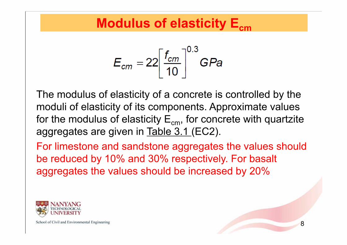
Modulus of elasticity Ecm
The modulus of elasticity of a concrete is controlled by the moduli of elasticity of its components. Approximate values for the modulus of elasticity Ecm, for concrete with quartzite aggregates are given in Table 3.1 (EC2).For limestone and sandstone aggregates the values should be reduced by 10% and 30% respectively. For basalt aggregates the values should be increased by 20%

9
Creep and ShrinkageCreep coefficient is determined by the following factors:
• Relative humidity • Element geometry• Strength class• Age at loading• Cement class• Stress/strength ratio at loading

10
Creep and ShrinkageTotal shrinkage strain is taken as the sum of the autogenous shrinkage and drying shrinkage strains:
εcs = εca + εcd
Autogenous shrinkage strain is related to concrete class.Drying shrinkage strain is affected by the following factors:
• Relative humidity • Element geometry• Strength class• Cement class
0
50
100
150
200
250
0 100 200 300 400
C50/60C45/55C40/50C35/45C30/37C25/30C20/25
C55/67C60/75
C70/85
C80/95
C90/105
Time (days)
Aut
ogen
ous
shrin
kage

11
Stress-strain relationsParabolic-Rectangular Bi-Linear
4
0.53
1 1 0
2.0 50
1.4 2.34 90 /100 50
2.0 50
2.0 0.085 50 503.5
n
cc cd c c2
c2
c cd c2 c cu2
ck
ck ck
c2 ck
c2 ck ck
cu2 ck
for
for for MPa
for MPa
for MPa
for MPafor
f
fn f
n f f
f
f ff
(?)
(?)
(?)
4
50
2.6 35 90 /100 50cu2 ck ck
MPa
for MPaf f (?)
4
1.75 50
1.75 0.55 50 / 40 50
3.5 50
2.6 35 90 /100 50
c3 ck
c3 ck ck
cu3 ck
cu3 ck ck
for MPa
for MPa
for MPa
for MPa
f
f f
f
f f
(?)
(?)
(?)
(?)

12
Stress-strain relations- higher strength concrete shows more brittle behavior.
concrete stress-strain relations under ambient temperature
0
10
20
30
40
50
60
70
0 0.0005 0.001 0.0015 0.002 0.0025 0.003 0.0035 0.004
C50/60C45/55C40/50C35/45C30/37C25/30C20/25
C55/67C60/75
C70/85
C80/95
C90/105
σc (MPa)
ε
Note: under elevated temperature (fire situation), no design recommendations beyond Class 1 Concrete Grade C60/75 in EC2 Part 1-2

13
EC2 permits a rectangular stress block to be used for section design
Rectangular stress distribution
λ = 0.8 for fck ≤ 50 MPaλ = 0.8 – (fck – 50)/400 for 50 < fck ≤ 90 MPa
η = 1.0 for fck ≤ 50 MPaη = 1.0 – (fck – 50)/200 for 50 < fck ≤ 90 MPa
fck (MPa) λ η
≤ 50 0.800 1.0060 0.775 0.9570 0.750 0.9080 0.725 0.8590 0.700 0.80
Stress-strain relations
λ: defining the effective height of the compression zone η: defining the effective strength.

14
Reinforcing steel
Reinforcing barsCoils
Welded fabric Lattice girders

Cold-reduced steel wires
Hot-rolled Wire RodDia. 5.5mm to 14mmYS : 300 N/mm2
Profiling Rollers- Dia. Reductione.g. 8mm > 7mmFinished Wire Coils
Dia. 5mm to 13mm,YS : 500 N/mm2
15

Welded fabric
Resistance Welding
Welded Mesh
Cold Rolled Wire
Straightening & Cutting
Computerised Machine
Wires in coil / pre-cut form
16

17
Reinforcing steel
EC2 does not cover the use of plain or mild steel reinforcement.Principles and rules are given for deformed bars, de-coiled rods, welded fabric and lattice girders.
There is no technical reason why other types of reinforcement should not be used. Relevant authoritative publications should be consulted when other types reinforcement are used.
EN 10080 provides the performance characteristic and testing methods but does not specify the material properties. These are given in Annex C of EC2.

18
Reinforcing steel Performance requirements
• Strength (fyk or f0.2k, ft)• Ductility (εuk and ft/fyk)• Weldability• Bendability • Bond characteristics (fR)

19
Reinforcing steel
Stress-strain relations for reinforcing steel
StrengthYield strength fyk or f0.2k and tensile strength ft.
Ductility Ratio of tensile strength to yield strength ft/fykElongation at maximum force εuk.
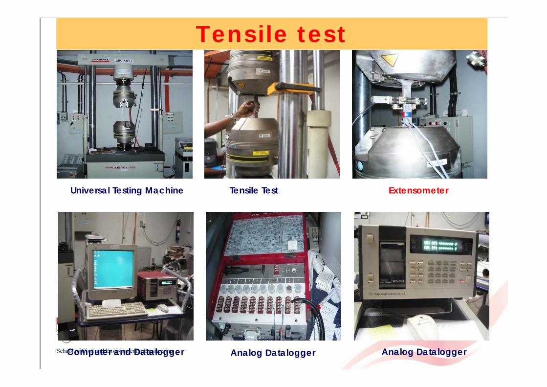
Tensile test
Universal Testing Machine Tensile Test Coupon Extensometer
Computer and Datalogger Analog Datalogger Analog Datalogger

21
WeldabilityWeldability is usually defined by two parameters: Carbon equivalent value (CEV) Limitations on the content of certain elements
The maximum values of individual elements and the carbon equivalent value are given below.
Table Chemical composition (% by mass)Carbon
Max.
Sulphur
Max.
Phosphorus
Max.
Nitrogen
Max.
Copper
Max.
CEV
Max.Cast analysis 0.22 0.050 0.050 0.012 0.80 0.50
Product analysis 0.24 0.055 0.055 0.014 0.85 0.52

22
Properties of reinforcement
Product form Bars and De-coiled rods Wire fabrics
Class A B C A B C
Characteristic yield strengthfyk or f0.2k (MPa) 400 to 600
k = (ft/fy)k ≥1.05 ≥1.08 ≥1.15<1.35 ≥1.05 ≥1.08 ≥1.15
<1.35
Characteristic strain at maximum force εuk(%) ≥2.5 ≥5.0 ≥7.5 ≥2.5 ≥5.0 ≥7.5
Bendability Bend/Re-bend test -
Maximum bar sizedeviation from ≤ 8mmnormal mass (%) > 8mm
± 6.0± 4.5
Properties of reinforcement (Annex C – EC2)
The UK has chosen a maximum value of characteristic yield strength, fyk= 600 MPa,But 500 MPa is the value assumed in BS4449 for normal supply.

23
Reduces congestion• Fewer bars needed• Increases bar spacing• Reduces bar diameter
Faster construction• Placing/tying bars (labor)• Less weight (crane)
Concrete placement is easier
Higher strength reinforcing steel
Advantage of higher strength reinforcing steel:
There is a push to use reinforcing steel with higher yield strength of 600 MPa because EC2 permits it but there is a lack of experiment data to calibrate/support its use.

24
Structural steel (EC3)
Performance requirements
• Strength — able to carry load
• Ductility — able to sustain permanent deformation
• Weldability — able to transfer load
• Toughness — able to absorb damage without fracture

25
High strength steel (HSS) Normal strength steel: Steel grades S235 to S460High strength steel: Steel grades greater than S460 up to S690
Compared to normal strength steel, high strength steel has lower ductility.

26
Why use HSS
When strength-to-weight is important, for example, inbridges to facilitate construction, retractable roofs andlifting crane structures.
Studies show that the ratio of the tensile residual stressto yield stress of the member seems to decrease withincreasing yield strength in hot-rolled sections.
More favorable buckling curves may be used for highstrength steel for S460.
Higher buckling resistance due to favorable bucklingcurves.

27
Buckling curves

28
Buckling curves

29
EC3 has additional ductility requirements compared to BS5950 in terms of stress ratio, %elongation and strain ratio.
Ductility requirements
Normal strength steel (fy ≤ 460 N/mm2)
• fu/fy ≥ 1.10
• Elongation at failure not less than 15%
• εu ≥ 15εy εy is the yield stain
High strength steel(460 N/mm2 < fy ≤ 700 N/mm2)
• fu/fy ≥ 1.05 (EC3-1-12)
• fu/fy ≥ 1.10 ( UK NA to EC3-1-12)
• Elongation at failure not less than 10%
• εu ≥ 15 εy

30
Some product standards have requirements on nominal yield and tensile strength, or their minimum values only. The stress ratio calculated according to these nominal values cannot comply with EC3, for e.g. profiled sheet sheeting..
Problem
Standard Grade Nominal yield strength (MPa) Nominal tensile strength (MPa) Stress ratio
AS 1397
G450 450 480 1.07
G500 500 520 1.04
G550 550 550 1.00
AS 1595 CA 500 500 510 1.02
EN 10149
S 550MC 550 600 1.09
S 600MC 600 650 1.08
S 650MC 650 700 1.08
S 700MC 700 750 1.07
EN 10326 S550GD 550 560 1.02
ISO 4997 CH550 550 550 1.00

31
Reinforcement Structural steelA B C Normal strength High strength
Yield strength (MPa) 400 to 600 ≤ 460 > 460
≤ 700Modulus of elasticity (GPa) 200 210
ft/fy or fu/fy ≥ 1.05 ≥ 1.08 ≥ 1.15< 1.35 ≥ 1.10 ≥ 1.05
≥ 1.10 (NA)Elongation (%) ≥ 2.5 ≥ 5.0 ≥ 7.5 ≥ 15 ≥ 10Ultimate strain εu ≥ 15εy
Comparison of structural steel and reinforcing steel
Structural steel and reinforcing steel

32
EC2 EC3 EC4
ConcreteNormal C12/15- C90/105
_C20/25 - C60/75
Light weight LC12/13 – LC80/88 LC20/22 - LC60/66
Reinforcing steel 400 - 600 N/mm2 _ 400 - 600 N/mm2
Structural steel _ ≤ 700 N/mm2 ≤ 460 N/mm2
Material comparison
These ranges in EC4 are narrower than those given in EC2 ( C12/15 –C90/105) and EC3 ( ≤ 700 N/mm2) because there is limited knowledgeand experimental data on composite members with very high strengthconcrete and high strength steel.
33
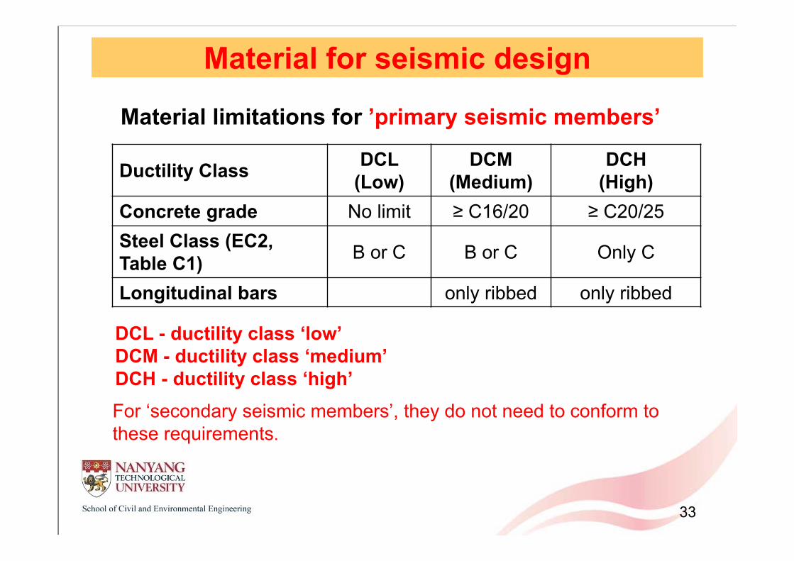
Material for seismic design
Ductility Class DCL (Low)
DCM (Medium)
DCH (High)
Concrete grade No limit ≥ C16/20 ≥ C20/25Steel Class (EC2, Table C1) B or C B or C Only C
Longitudinal bars only ribbed only ribbed
Material limitations for ’primary seismic members’
DCL - ductility class ‘low’DCM - ductility class ‘medium’DCH - ductility class ‘high’For ‘secondary seismic members’, they do not need to conform to these requirements.

34
Detailing for seismic designIn addition, for seismic detailing, there are stringent requirements for reinforcing steel mainly focusing on:
Bar diameter Bar spacing Minimum bar numbers Minimum reinforcement area Maximum reinforcement area

35
Detailing of primary seismic beams
For DCL following EC2 For DCM&DCH critical regions (detailing to EC8)
out of critical regions (detailing to EC2)
Critical region lcr = hw (depth of beam) for DCMlcr = 1.5hw for DCH
< 50 mm
lcr
Standard Detailing to EC2
s
h w
lcr
critical region critical region
Beam-column Joint “special” confinement toclause 5.4.3.3 (EC8)

36
DCH DCM DCLLongitudinal barsρmin 0.5 fctm/fyk (EC2)ρmax ρ'+0.0018fcd/(μφεsy,dfyd) 0.04 (EC2)
dbl/hc bar crossing interior joint -
dbl/hc bar anchored at exterior joint -
Transverse reinforcement
Out critical regions
spacing Min {0.75d; 15Φ; 600} (EC2)
ρmin (EC2)
In critical regions
dbw,min 6mm -
spacing Min{hw/4;24dbw;175;6dbl} Min{hw/4;24dbw;225;8dbl} -
ctm ykMax 0.26f f ; 0.13%
d ctm
yd
max
6.25 1+0.8v ffρ1+0.75
ρ
7.5 d ctm
yd
max
1+0.8v ffρ1+0.5
ρ
ctmd
yd
f6.25 1+0.8vf
7.5 ctmd
yd
f1+0.8vf
Detailing of primary seismic beams
ck yk0.08 f f

37
Detailing of primary seismic columns
l crs
l cr
criticalregion
criticalregion
horizontal confinement reinforcementin beam-column joint not less than
that in critical region of column
For DCL detailing to EC2
For DCM&DCH critical regions (detailing to EC8)out of critical regions (detailing to EC2)
Critical region
for DCMfor DCH
hc is the largest cross-sectional dimension of columnlcl is the clear length of the column
max ; 6;0.45cr c cll h l
max 1.5 ; 6;0.6cr c cll h l
Beam-column joint “special” confinement toclause 5.4.3.3 (EC8)

38
Detailing of primary seismic columnsDCH DCM DCL
Cross-section hc,bc,min 250 mm - -Longitudinal barsρmin 1% (EC2)ρmax 4% 4% (EC2)dbl,min 8 mmBars per column side 3 2 (EC2)Transverse reinforcementOut critical regionsspacing Min {20dbl;bc; hc; 400} (EC2)dbw Max {0.25dbl; 6} (EC2)Within critical regionsdbw,min Max {0.25dbl; 6} (EC2)spacing Min{b0/3;125;6dbl} Min{b0/2;175;8dbl} -Volumetric ratio ωwd 0.08 -αωwd -In critical region at column base:ωwd 0.12 0.08 -αωwd -
Ed yd cMax 0.1N f ; 0.002A
bl yd ywdMax 6;0.4d f f
φ d sy,d c 030μ ν ε b b -0.05
φ d sy,d c 030μ ν ε b b -0.05

39
Detailing for primary seismic wallsDCH DCM DCL
Boundary elements:In critical region:Longitudinal barsρmin 0.5% 0.2% (EC2)ρmax 4% (EC2)Transverse barsdbw,min 6 mm Max {0.25dbl; 6} (EC2)spacing Min{b0/3;125;6dbl} Min{b0/2;175;8dbl} Min {20dbl;bc; hc; 400} (EC2)Volumetric ratio ωwd 0.12 0.08 -αωwd -Web:Vertical barsρv,min Wherever εc >0.2%: 0.5%; elsewhere 0.2% 0.2% (EC2)ρv,max 4% (EC2)dbv,min 8mm -dbv,max bwo/8 -spacing Min (25dbv; 250mm) Min (3bwo; 400mm) (EC2)Horizontal barsρh,min 0.2% Max (0.2%; 0.25ρv) (EC2)dbv,min 8mm -dbv,max bwo/8 -spacing Min (25dbh; 250mm) 400mm (EC2)
bl yd ywdMax 6;0.4d f f
φ d sy,d c 030μ ν ε b b -0.05

40
Conclusions There is clear advantage in using higher strength grade
concrete, reinforcing steel and structural steel but there are still some work to be done.
Be careful with some products; they may not comply with more stringent Eurocode ductility requirements, for e.g. AS1397, SS2 vs. SS560, etc.
For seismic design, there are more stringent requirements for ductility in reinforcing steel in terms of higher steel class (B or C only).
In addition, there are stringent requirements for seismic detailing for reinforcing steel in terms of bar diameter and bar spacing, and minimum and maximum reinforcement.