materials and methods for corrosion control of reinforced and
TRANSCRIPT

Materials and Methods for CorrosionControl of Reinforced and PrestressedConcrete Structures in NewConstruction
Research, Development, and TechnologyTurner-Fairbank Highway Research Center6300 Georgetown PikeMcLean, VA 22101-2296
PUBLICATION NO. 00-081 AUGUST 2000

FOREWORD
Salt-induced reinforcing steel corrosion in concrete bridges has undoubtedly become a considerableeconomic burden to many State and local transportation agencies. Since the iron in the steel has anatural tendency to revert eventually to its most stable oxide state, this problem will, unfortunately, stillbe with us, but to a much lesser degree due to the use of various corrosion protection strategiescurrently used in new construction. The adoption of corrosion protection measures in new construction,such as the use of good design and construction practices, adequate concrete cover depth,low-permeability concrete, corrosion inhibitors, and coated reinforcing steel, is significantly reducing theoccurrence of reinforcing steel corrosion in new bridges. This report summarizes the results of variousresearch investigations in developing and evaluating the performance of various corrosion protectionsystems. This report describes materials and measures that can be used for corrosion control inreinforced and prestressed concrete bridge structures in new construction.
This report will be of interest to materials and bridge engineers, reinforced concrete corrosionspecialists, and those concerned with the performance of reinforced and prestressed concrete bridges.
T. Paul Teng, P.E.Director, Office of Infrastructure Research and Development
NOTICE
This document is disseminated under the sponsorship of the Department of Transportation in theinterest of information exchange. The United States Government assumes no liability for its contents oruse thereof. This report does not constitute a standard, specification, or regulation.
The United States Government does not endorse products or manufacturers. Trade and manufacturers’names appear in this report only because they are considered essential to the object of the document.

10. Work Unit No. (TRAIS)
14. Sponsoring Agency Code
7. Author(s)J.L. Smith* and Y.P. Virmani**
13. Type of Report and Period Covered
Final Report
1. Report No.
FHWA-RD-00-081
2. Government Accession No.
4. Title and SubtitleMATERIALS AND METHODS FOR CORROSION CONTROL OF REINFORCEDAND PRESTRESSED CONCRETE STRUCTURES IN NEW CONSTRUCTION
3. Recipient's Catalog No.
17. Key WordsReinforced concrete, prestressed concrete, chlorides,corrosion, corrosion protection, reinforcing steel, grout,corrosion inhibitors.
18. Distribution StatementNo restrictions. This document is available to the public throughthe National Technical Information Service, Springfield, Virginia22161.
16. AbstractSalt-induced reinforcing steel corrosion in concrete bridges has undoubtedly be come a considerable economic burden to manyState and local transportation agencies. Since the iron in the steel has a nat ural tendency to revert eventually to its most stableoxide state, this problem will, unfortunately, still be with us, but to a much lesser degree due to the use of various corrosionprotection strategies currently used in new construction. The adoption of corr osion protection measures in new construction,such as the use of good design and construction practices, adequate concrete co ver depth, low-permeability concrete, corrosioninhibitors, and coated reinforcing steel is significantly reducing the occurren ce of reinforcing steel corrosion in new bridges.
Because concrete has a tendency to crack, the use of good design and constructi on practices, adequate concrete cover depth,corrosion-inhibiting admixtures, and low-permeability concrete alone will not a bate the problem. Even corrosion-inhibitingadmixtures for concrete would probably not be of use when the concrete is crack ed. This situation essentially leaves thereinforcing steel itself as the last line of defense against corrosion, and the use of a barrier system on the reinforcing steel, suchas epoxy coating, another organic coating, or metallic coatings, is even more c ritical.
It is likely that there may never be any organic coating that can withstand the extreme combination of constant wetting and hightemperature and high humidity that reinforcing steel is exposed to in some mari ne environments. Either steel bars coated with asufficiently stable metallic coating or some type of corrosion-resistant solid metal bars would have to be used. There are somevery convincing reports of good corrosion-resistance performance shown by epoxy -coated steel bars in concrete bridge deckswhere the concrete does not remain constantly wet and other exposure conditions are not as severe. Recent improvements tothe epoxy coating specifications and the tightening of requirements on the prop er storage and handling of epoxy-coatedreinforcing steel at construction sites will ensure good corrosion protection.
For construction of new prestressed concrete bridge members (where for structur al or other considerations epoxy-coatedstrands cannot be used), the use of a corrosion-inhibitor admixture in the conc rete or in the grout, in conjunction with goodconstruction designs and practices, would provide adequate corrosion protection . However, the long-term effectiveness of allcommercial inhibitor admixtures has not been fully verified
15. Supplementary Notes
19. Security Classif. (of this report)
Unclassified
20. Security Classif. (of this page)
Unclassified
21. No. of Pages
82
22. Price
8. Performing Organization Report No.
11. Contract or Grant No.
Technical Report Documentation Page
5. Report Date
6. Performing Organization Code
HRDI-09 and HIO-SO
Form DOT F 1700.7 (8-72) Reproduction of completed page authorized
9. Performing Organization Name and Address* Southern Resource Center ** Office of Infrastructure R&DFederal Highway Administration Federal Highway Administration61 Forsyth Street, SW, Suite 17T26 6300 Georgetown PikeAtlanta, Georgia 30303-3104 McLean, Virginia 22101-229612. Sponsoring Agency Name and AddressOffice of Infrastructure Research and DevelopmentFederal Highway Administration6300 Georgetown PikeMcLean, Virginia 22101-2296
This form was electronically produced by Elite Federal Forms, Inc.

iii
TABLE OF CONTENTS
Page No.
INTRODUCTION . . . . . . . . . . . . . . . . . . . . . . . . . . . . . . . . . . . . . . . . . . . . . . . . . . . . . . . . . . . . 1
CORROSION PROCESS . . . . . . . . . . . . . . . . . . . . . . . . . . . . . . . . . . . . . . . . . . . . . . . . . . . . 3
CORROSION CONTROL MEASURES . . . . . . . . . . . . . . . . . . . . . . . . . . . . . . . . . . . . . . . . 14
GENERAL DESIGN PROVISIONS . . . . . . . . . . . . . . . . . . . . . . . . . . . . . . . . . . . . . . . . . . . . 17
GENERAL CONSTRUCTION PROVISIONS . . . . . . . . . . . . . . . . . . . . . . . . . . . . . . . . . . . 20
CONCRETE . . . . . . . . . . . . . . . . . . . . . . . . . . . . . . . . . . . . . . . . . . . . . . . . . . . . . . . . . . . . . . . 22
PRESTRESSED CONCRETE . . . . . . . . . . . . . . . . . . . . . . . . . . . . . . . . . . . . . . . . . . . . . . . . . 27
POST-TENSIONED CONCRETE . . . . . . . . . . . . . . . . . . . . . . . . . . . . . . . . . . . . . . . . . . . . . 30
GROUTS FOR BONDED POST-TENSIONED CONCRETE . . . . . . . . . . . . . . . . . . . . . . . 33
TEST METHODS FOR BONDED POST-TENSIONED CONCRETE . . . . . . . . . . . . . . . . 43
CORROSION INHIBITORS . . . . . . . . . . . . . . . . . . . . . . . . . . . . . . . . . . . . . . . . . . . . . . . . . 47
FIELD PERFORMANCE OF EPOXY-COATED REINFORCING STEEL . . . . . . . . . . . . 51
CORROSION-RESISTANT REINFORCING BARS . . . . . . . . . . . . . . . . . . . . . . . . . . . . . 60
SUMMARY . . . . . . . . . . . . . . . . . . . . . . . . . . . . . . . . . . . . . . . . . . . . . . . . . . . . . . . . . . . . . . . 66
REFERENCES . . . . . . . . . . . . . . . . . . . . . . . . . . . . . . . . . . . . . . . . . . . . . . . . . . . . . . . . . . . . . 68

iv
LIST OF FIGURES
Figure No. Page No.
1. Corrosion-induced deterioration on a bridge column . . . . . . . . . . . . . . . . . . . . . . . . . . . . . . 12. Electrochemical corrosion cell . . . . . . . . . . . . . . . . . . . . . . . . . . . . . . . . . . . . . . . . . . . . . . . 33. Corrosion cell in reinforced concrete . . . . . . . . . . . . . . . . . . . . . . . . . . . . . . . . . . . . . . . . . . 44. Microcell versus macrocell corrosion . . . . . . . . . . . . . . . . . . . . . . . . . . . . . . . . . . . . . . . . . . 45. Electrolytic corrosion of reinforcement in concrete exposed to chloride and moisture . . . . . . . 56. Passivated steel in concrete . . . . . . . . . . . . . . . . . . . . . . . . . . . . . . . . . . . . . . . . . . . . . . . . . 57. Three-dimensional plot of oxygen concentration, chloride concentration, and pH,
illustrating regions of corrosion and no corrosion . . . . . . . . . . . . . . . . . . . . . . . . . . . . . . . . . 98. Simple deterioration model, corrosion of steel in concrete . . . . . . . . . . . . . . . . . . . . . . . . . . . 10
LIST OF TABLES
Table No. Page No.
1. Summary of the effects of material variables on concrete properties and corrosionbehavior . . . . . . . . . . . . . . . . . . . . . . . . . . . . . . . . . . . . . . . . . . . . . . . . . . . . . . . . . . . . . . . 23
2. ACI-recommended chloride limits for new construction . . . . . . . . . . . . . . . . . . . . . . . . . . . . 263. Grout mix proportions for Classes A, B, and C . . . . . . . . . . . . . . . . . . . . . . . . . . . . . . . . . . 394. Minimum testing requirements . . . . . . . . . . . . . . . . . . . . . . . . . . . . . . . . . . . . . . . . . . . . . . . 425. Calcium nitrite dosage rates . . . . . . . . . . . . . . . . . . . . . . . . . . . . . . . . . . . . . . . . . . . . . . . . . 49

1
Figure 1. Corrosion-induceddeterioration on a bridge column.
INTRODUCTION
The deterioration of reinforced concrete structures is a major problem. The cost of repairing orreplacing deteriorated structures has become a major liability for highway agencies, estimated to be
more than $20 billion and to be increasing at $500million per year.(1) The primary cause of this deterioration(cracking, delamination, and spalling) is the corrosion ofsteel reinforcing bars due to chlorides. The two mainsources of chlorides are deicing chemicals and seawater.The bare pavement policies of many highway agenciesfor winter snow and ice removal have resulted inextensive use of salt-based deicing chemicals. The mostcommon chemical used has been sodium chloride. Manybridges have also been built in coastal areas and areexposed to seawater.
Bridges built with black reinforcing steel are showingprogressive concrete deterioration as the concentrationof chloride ions increases. According to a May 1997report, The Status of the Nation’s Highway Bridges:Highway Bridge Replacement and RehabilitationProgram and National Bridge Inventory, ThirteenthReport to the United States Congress, about 80,000
bridges on the Federal-aid system and 103,000 bridges off the Federal-aid system are deficient in someway. This includes both structurally deficient and functionally obsolete bridges. The average bridgedeck located in a snow-belt State with black reinforcing steel and 40 mm (1.5 in) of concrete cover hasshown spalling in about 7 to 10 years after construction and has required rehabilitation in about 20years after construction.
The increase in the amount and severity of bridge deck deterioration in the late 1960's and early 1970'salarmed the State Highway Agencies and posed serious safety hazards to the traveling motorist. As aresult several measures have been developed and implemented to prevent the chloride-inducedcorrosion of steel reinforcing bars and the resulting deterioration. Some of the early measures usedincluded lowering the water-cement ratio of the concrete and increasing the concrete cover over thesteel reinforcing bars. Concrete permeability can also be reduced by the use of admixtures. Corrosioninhibitors are also being used. Epoxy-coated reinforcing steel (ECR) was introduced in the mid 1970'sas a protection system for new bridge decks. Another protection measure is the use of corrosion-resistant solid reinforcing bars or clad black reinforcing bars. The use of waterproof membranes inconjunction with asphaltic concrete overlays as a protective system has produced variable results. Amultiple protection strategy is the simultaneous use of two or more protection measures, such as epoxy-coated reinforcing steel and a corrosion inhibitor.

2
The use of prestressed concrete members in bridges is a relatively new practice and consequently mostbridge applications are relatively young. As a result, corrosion-induced deterioration of these membersonly became evident in the early 1980's. Although prestressed concrete members are generallymanufactured with a higher strength concrete under better quality control, they are subject to the sameeffects of corrosion as is conventionally reinforced concrete. However, because of the high stresses inthe prestressing strands, the corrosion process is accelerated. Even small corrosion pits could cause astrand to fracture, compared to conventional reinforcing that may rust to virtually nothing beforebreaking. There have been documented cases of prestressing strands breaking due to corrosion. This isa serious problem as prestressed concrete members rely on the tensile strength of the strands to resistapplied loads.
Protective systems for prestressed concrete bridge superstructure members (girders and beams) andsubstructure members (piles, piers, etc.) are still under investigation and are being improved anddeveloped further. These members are generally built with black prestressing steel. Current researchshows promise for the use of epoxy-coated prestressing strands for prestressed concrete members. Asof now, there is no generally accepted protective system for concrete bridge substructure members orprestressed concrete bridge members. However, because of the use of uncoated prestressing steel, theuse of corrosion inhibitors in prestressed, concrete members has gained acceptance.
For most corrosion-protection measures, the basic principle is to prevent the chloride ions fromreacting with the steel surface and also to increase the time needed for the chloride ions to penetratethrough the concrete cover. While these measures generally do not stop corrosion from eventuallyinitiating, they do increase the service life of reinforced concrete structures by slowing the corrosionprocess. Cathodic protection, however, has proven to be a successful corrosion-protection measure forconventionally reinforced and pretensioned, prestressed concrete bridge members.

3
Figure 2. Electrochemical corrosion cell.
CORROSION PROCESS
The corrosion of steel reinforcing bars is an electrochemical process that requires a flow of electriccurrent and several chemical reactions. The three essential components of a galvanic corrosion cell are:
< Anode.< Cathode.< Electrolyte.
The general relationship between the components of a corrosion cell is illustrated in figure 2.(2)
The anode and cathode can be on the same steel reinforcing bar. Figure 3 illustrates a corrosion cell fora steel reinforcing bar embedded in concrete.(2) The anode is the location on a steel reinforcing barwhere corrosion is taking place and metal is being lost. At the anode, iron atoms lose electrons to
become iron ions (Fe+2). This oxidation reaction is referred to as the anodic reaction. The cathode isthe location on a steel reinforcing bar where metal is not consumed. At the cathode, oxygen, in thepresence of water, accepts electrons to form hydroxyl ions (OH-). This reduction reaction is referred toas the cathodic reaction.
The electrolyte is the medium that facilitates the flow of electrons (electric current) between the anodeand the cathode. Concrete, when exposed to wet-dry cycles, has sufficient conductivity to serve as anelectrolyte.
Both the anodic and cathodic reactions are necessary for the corrosion process to occur and they needto take place concurrently. The anode and cathode can be located next to each other or can be separated. When they are located immediately next to each other, i.e., on a
4
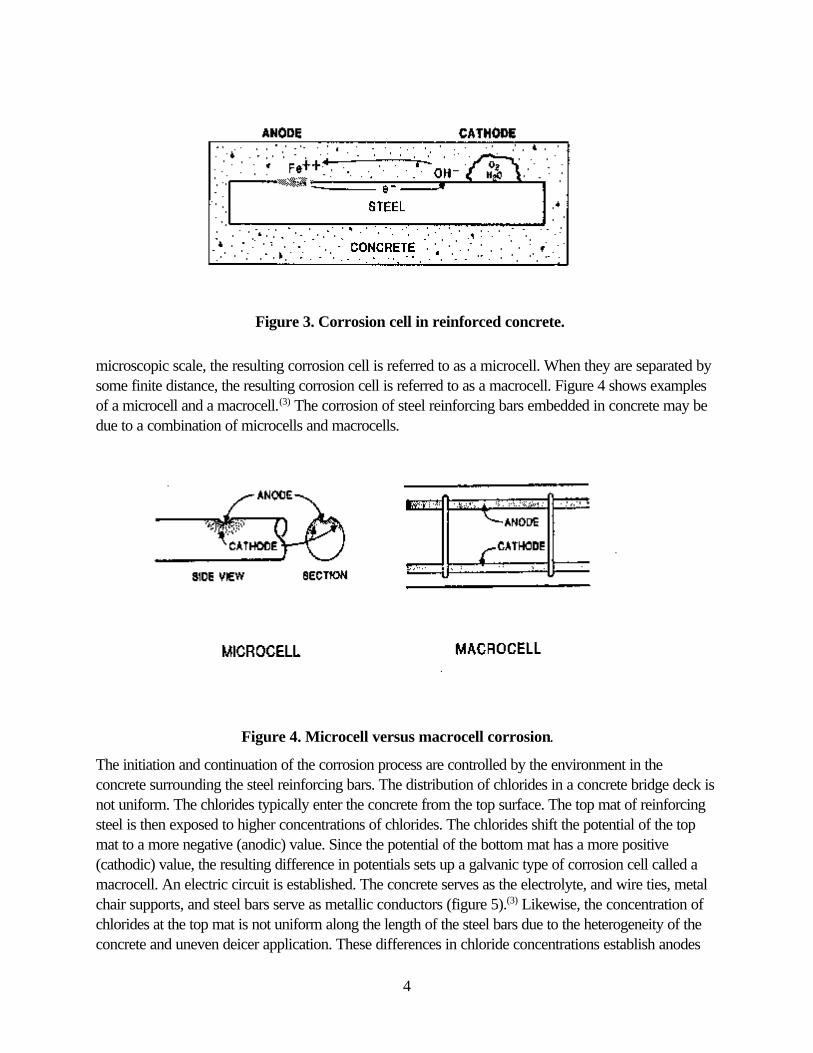
Figure 3. Corrosion cell in reinforced concrete.
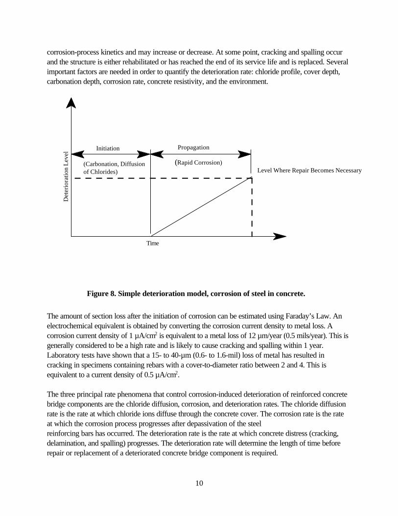
Figure 4. Microcell versus macrocell corrosion.
microscopic scale, the resulting corrosion cell is referred to as a microcell. When they are separated bysome finite distance, the resulting corrosion cell is referred to as a macrocell. Figure 4 shows examplesof a microcell and a macrocell.(3) The corrosion of steel reinforcing bars embedded in concrete may bedue to a combination of microcells and macrocells.
The initiation and continuation of the corrosion process are controlled by the environment in theconcrete surrounding the steel reinforcing bars. The distribution of chlorides in a concrete bridge deck isnot uniform. The chlorides typically enter the concrete from the top surface. The top mat of reinforcingsteel is then exposed to higher concentrations of chlorides. The chlorides shift the potential of the topmat to a more negative (anodic) value. Since the potential of the bottom mat has a more positive(cathodic) value, the resulting difference in potentials sets up a galvanic type of corrosion cell called amacrocell. An electric circuit is established. The concrete serves as the electrolyte, and wire ties, metalchair supports, and steel bars serve as metallic conductors (figure 5).(3) Likewise, the concentration ofchlorides at the top mat is not uniform along the length of the steel bars due to the heterogeneity of theconcrete and uneven deicer application. These differences in chloride concentrations establish anodes

5
Figure 5. Electrolytic corrosion of reinforcement in concrete exposed tochloride and moisture.
Figure 6. Passivated steel in concrete.
and cathodes on individual steel bars in the top mat and result in the formation of microcells.
Concrete is alkaline due to the presence of Ca(OH)2, KOH, and NaOH and has an alkalinity typicallybetween pH 12 and 13. The concrete pore solution consists primarily of KOH and NaOH. Due to thehigh alkalinity of the concrete porewater, the steel reinforcing bars are passivated by an iron oxide film(ã @ Fe2O3) that protects the steel (figure 6).(2) The oxide film itself is a product of the initial corrosion ofthe steel reinforcing bar. In the initial stages of corrosion, a ferrous hydroxide (Fe(OH)2) compound isformed. Ferrous hydroxide has low solubility and, in the presence of oxygen and water, is oxidized toiron oxide (Fe2O3) to form the passivation film. As the film is being formed, the oxygen diffusion rate isreduced, which, in turn, reduces the corrosion rate.

6
In order for corrosion to occur, the steel reinforcing bar needs to be depassivated. Oxygen, water, andan aggressive ion such as chloride need to be available, and the concrete needs to have low resistivity.In addition, all conditions need to be present simultaneously.
However, the intrusion of chloride ions is the most important factor in the corrosion of steel reinforcingbars embedded in concrete. Possible sources of chlorides include:
< Aggregates.< Mix water.< Admixtures (in particular, accelerators).< Deicing chemicals.< Seawater.
The chloride content of portland cement, fly ash, and silica fume is typically very low. However, thechloride content of ground granulated blast-furnace slag is variable and depends on the water used inthe quenching process. The chloride content can be significantly high if saltwater is used.
Aggregates may contain chlorides, especially if they are obtained from sites associated with seawater orwith groundwater containing chlorides. Depending on the amount of chlorides present in the aggregatesand the mix proportions, it is possible to produce a concrete that already has a chloride concentrationat or above the limit for corrosion initiation.
Potable water can contain small amounts of chlorides (20 to 100 ppm). This amount of chlorides isgenerally considered to be insignificant. When used in concretes with typical mix proportions, theresulting concrete has a chloride concentration that is much lower than the threshold limit.
Besides admixtures based on calcium chloride (CaCl2), some water reducers and setting admixturescontain chlorides. The amount is considered to be insignificant if the chloride content is less than 0.01percent by mass of the cementitious material. The use of admixtures should be evaluated on a case-by-case basis for any impacts on the corrosion process. Calcium formate, sodium thiocyanate, calciumnitrate, and calcium nitrite are the commonly used chemicals. Calcium nitrite has been shown to be aneffective corrosion inhibitor for steel embedded in concrete. Non-chloride accelerators should not beassumed to be non-corrosive. Sodium thiocyanate in high dosage rates has been reported to promotecorrosion.
The process by which steel reinforcing bars are depassivated is not fully understood. Several theorieshave been presented to explain the role of chloride ions. Chloride ions reach the reinforcing steel bypenetrating the concrete via the porewater and through cracks in the concrete. In the oxide film theory,the chloride ions break down the passive oxide film. At this point, the steel reinforcing bar becomesdepassivated and corrosion may be initiated. In the adsorption theory, chloride ions are adsorbed intothe surface of the steel reinforcing bar and attack the steel directly. In the transitory complex theory,chloride ions act as a catalyst. The chloride ions combine with the ferrous ions to form a soluble iron-chloride complex that diffuses away from the anode. Subsequent breakdown of the iron-chloride

7
complex frees the chloride ions for reuse when ferrous hydroxide is formed.
When carbon dioxide (CO2) penetrates concrete and dissolves in the pore solution, carbonic acid isformed. This acid reacts with the alkali in the cement to form carbonates and to lower the pH of theconcrete. When the alkalinity reaches a low enough level, the steel reinforcing bar becomesdepassivated and, in the presence of sufficient water and oxygen, corrosion is initiated and proceeds.However, carbonation advances very slowly in sound concrete and is generally not a factor.
The corrosion of steel in concrete in the presence of oxygen, but without chlorides, takes place inseveral steps:
1. At the anode, iron is oxidized to the ferrous state and releases electrons.
Fe ÷ Fe++ + 2e-
2. These electrons migrate to the cathode where they combine with water and oxygen to formhydroxyl ions.
2e- + H2O + ½O2 ÷ 2OH-
3. The hydroxyl ions combine with the ferrous ions to form ferrous hydroxide.
Fe++ + 2OH- ÷ Fe(OH)2
4. In the presence of water and oxygen, the ferrous hydroxide is further oxidized to form Fe2O3.
4Fe(OH)2 + O2 + H2O ÷ 4Fe(OH)3
2Fe(OH)3 ÷ Fe2O3 @ 2H2O
The corrosion of steel in concrete in the presence of chlorides, but with no oxygen (at the anode), takesplace in several steps:
1. At the anode, iron reacts with chloride ions to form an intermediate soluble iron-chloridecomplex.(4)
Fe + 2Cl- ÷ (Fe++ + 2Cl-) + 2e-
2. When the iron-chloride complex diffuses away from the bar to an area with a higher pH andconcentration of oxygen, it reacts with hydroxyl ions to form Fe(OH)2. This complex reactswith water to form ferrous hydroxide.(5)
(Fe++ + 2Cl-) + 2H2O + 2e- ÷ Fe(OH)2 + 2H+ + 2Cl-

8
3. The hydrogen ions then combine with electrons to form hydrogen gas.
2H+ + 2e- ÷ H28
4. As in the case of the corrosion of steel without chlorides, the ferrous hydroxide, in the presenceof water and oxygen, is further oxidized to form Fe2O3.
4Fe(OH)2 + O2 + H2O ÷ 4Fe(OH)3
2Fe(OH)3 ÷ Fe2O3 @ 2H2O
The corrosion products resulting from the corrosion of steel reinforcing bars occupy a volume equal tothree to six times that of the original steel. This increase in volume induces stresses in the concrete thatresult in cracks, delaminations, and spalls. This accelerates the corrosion process by providing an easypathway for the water and chlorides to reach the steel.
There are two main types of chloride contents that are tested for and reported – acid-soluble chlorides,sometimes referred to as total chlorides, and water-soluble chlorides. Acid-soluble chlorides are thechlorides extracted from a concrete sample using an acid. Water-soluble chlorides are those chloridespresent that can dissolve in water. The amount of water-soluble chlorides is less than the total or acid-soluble amount of chlorides present in a concrete sample.
The minimum chloride ion concentration needed to initiate corrosion of steel reinforcing bars is alsocalled the corrosion chloride threshold. Although the concept of a chloride threshold is generallyaccepted, there is little agreement on what the threshold value is. Several factors influence the chloridethreshold value: the composition of the concrete (resistivity), the amount of moisture present, and theatmospheric conditions (temperature and humidity). The threshold concentration depends on the pHlevel and the concentration of oxygen. When chlorides are uniformly distributed, higher concentrationsare needed to initiate corrosion. The amount of tricalcium aluminate (C3A) present in the cementinfluences the threshold level. Regardless of what concentration of chloride ions is needed to initiatecorrosion, an increase in the chloride ion concentration increases the probability that corrosion of thesteel reinforcing bars will occur.
In general, the concentration of chloride ions needs to be more than 0.71 kg/m3 (1.2 lb/yd3). The ratioof chloride ions to hydroxyl ions also needs to be greater than 0.6.(5) However, the corrosion of steelreinforcing bars embedded in concrete is a complex process. The use of a single value or criteria for achloride threshold may not be appropriate or accurate. This is illustrated in figure 7, which shows thatthe chloride threshold may be dependent on both pH and oxygen concentration.(6)
Whenever a difference in potentials on a metallic surface or between two metals is established,corrosion is initiated. This potential difference is referred to as the driving force. One area on thesurface of the metal or one of the metals displays anodic behavior and the other displays cathodicbehavior. Potential differences can be due to variations in the composition of the metal or in theenvironment surrounding the metal. Variations in the environment may be due to differences in pH,

9
Figure 7. Three-dimensional plot of oxygenconcentration, chloride concentration, and pH,
illustrating regions of corrosion and no corrosion.
oxygen concentration, chloride concentration, moisture, or temperature. When the corrosion cell iscreated as a result of differences in the concentration of oxygen, chloride, or water, the cell is referredto as a concentration cell.
The four stages of chloride-induced deterioration of reinforced concrete are:
1. Chloride contamination and corrosion initiation.
2. Cracking – Occurs when the corrosion-induced tensile stresses exceed the tensile strength ofthe concrete (can be inclined or parallel to the roadway surface).
3. Delamination – Occurs when the cracks are parallel to the roadway surface and results in afracture plane (often at the rebar level).
4. Spalling – When inclined cracks reach the roadway surface, freeze-thaw cycles and trafficloading cause the cracked delaminated portions to break away (accelerates the corrosionprocess).
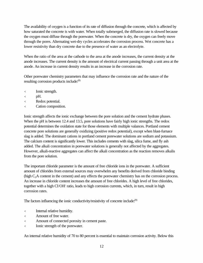
A simple model for the corrosion of steel in concrete is shown in figure 8.(7) This service-life model forreinforced concrete structures has two stages – initiation and propagation. This model depicts the timeto corrosion initiation and the subsequent deterioration rate. Some structures have been found to followthis model with reasonable accuracy. The initiation time is the length of time until depassivation of thesteel reinforcing bars and the initiation of corrosion have occurred. The corrosion rate is controlled by
10
Figure 8. Simple deterioration model, corrosion of steel in concrete.
Det
erio
ratio
n L
evel
PropagationInitiation
(Rapid Corrosion)(Carbonation, Diffusionof Chlorides)
Time
Level Where Repair Becomes Necessary
corrosion-process kinetics and may increase or decrease. At some point, cracking and spalling occurand the structure is either rehabilitated or has reached the end of its service life and is replaced. Severalimportant factors are needed in order to quantify the deterioration rate: chloride profile, cover depth,carbonation depth, corrosion rate, concrete resistivity, and the environment.
The amount of section loss after the initiation of corrosion can be estimated using Faraday’s Law. Anelectrochemical equivalent is obtained by converting the corrosion current density to metal loss. Acorrosion current density of 1 µA/cm2 is equivalent to a metal loss of 12 µm/year (0.5 mils/year). This isgenerally considered to be a high rate and is likely to cause cracking and spalling within 1 year.Laboratory tests have shown that a 15- to 40-µm (0.6- to 1.6-mil) loss of metal has resulted incracking in specimens containing rebars with a cover-to-diameter ratio between 2 and 4. This isequivalent to a current density of 0.5 µA/cm2.
The three principal rate phenomena that control corrosion-induced deterioration of reinforced concretebridge components are the chloride diffusion, corrosion, and deterioration rates. The chloride diffusionrate is the rate at which chloride ions diffuse through the concrete cover. The corrosion rate is the rateat which the corrosion process progresses after depassivation of the steelreinforcing bars has occurred. The deterioration rate is the rate at which concrete distress (cracking,delamination, and spalling) progresses. The deterioration rate will determine the length of time beforerepair or replacement of a deteriorated concrete bridge component is required.

11
FACTORS INFLUENCING THE CHLORIDE DIFFUSION RATE
The main factor that controls the diffusion of chloride ions in concrete is concrete permeability.Concrete permeability can be reduced by:
< Reducing the water-cement ratio of the concrete.< Adding pozzolanic and pozzolanic/cementitious materials to the concrete.< Adding polymer modifiers to the concrete.< Aggregate gradation.
Some other factors influencing the diffusion of chloride ions in concrete include:(8)
< Surface charge on the hydrated cement paste.< Formation of porous transition zones at the aggregate/cement paste interface.< Microcracking.
An increase in microcracking can increase the rate of chloride ion permeability for structures subjectedto cyclic loadings. Static compressive stresses do not appear to have any significant effect on chlorideion permeability. However, concrete exhibits a significant increase in permeability when loaded withcyclic compressive loads that are 60 to 80 percent of its ultimate strength. The rate of chloride ionpermeability increases as residual strength decreases.
The prediction/calculation of chloride penetration into concrete is generally done using Fick’s SecondLaw. However, the application of Fick’s Second Law to predict chloride penetration yields results thatare very conservative. This is mainly due to the description of concrete as a homogeneous medium tomodel the transport of dissolved ions (i.e., it is too simple a model and is not due to any fundamentalproblem with Fick’s Law). In addition, the prediction of chloride ion penetration using diffusivity maybe uncertain as the assumption of a constant chloride ion diffusivity is seldom seen in real structures.
FACTORS INFLUENCING CORROSION RATE
Once a sufficient amount of chlorides has reached the steel reinforcing bars to depassivate the bars andinitiate corrosion, factors influencing the corrosion rate of steel reinforcing bars embedded in concreteinclude:(8)
< Availability of water and oxygen.< Ratio of the steel surface area at the anode to that at the cathode.< Amount of chloride ions in the porewater.< Resistivity of the concrete.< Temperature.< Relative humidity (both internal and external).< Concrete microstructure.
12
The availability of oxygen is a function of its rate of diffusion through the concrete, which is affected byhow saturated the concrete is with water. When totally submerged, the diffusion rate is slowed becausethe oxygen must diffuse through the porewater. When the concrete is dry, the oxygen can freely movethrough the pores. Alternating wet-dry cycles accelerates the corrosion process. Wet concrete has alower resistivity than dry concrete due to the presence of water as an electrolyte.
When the ratio of the area at the cathode to the area at the anode increases, the current density at theanode increases. The current density is the amount of electrical current passing through a unit area at theanode. An increase in current density results in an increase in the corrosion rate.
Other porewater chemistry parameters that may influence the corrosion rate and the nature of theresulting corrosion products include:(8)
< Ionic strength.< pH.< Redox potential.< Cation composition.
Ionic strength affects the ionic exchange between the pore solution and the cement hydrate phases.When the pH is between 12.4 and 13.5, pore solutions have fairly high ionic strengths. The redoxpotential determines the oxidation state for those elements with multiple valances. Portland cementconcrete pore solutions are generally oxidizing (positive redox potential), except when blast-furnaceslag is added. The dominant cations in portland cement porewater solutions are sodium and potassium.The calcium content is significantly lower. This includes cements with slag, silica fume, and fly ashadded. The alkali concentration in porewater solutions is generally not affected by the aggregates.However, alkali-reactive aggregates can affect the alkali concentration as the reaction removes alkalisfrom the pore solution.
The important chloride parameter is the amount of free chloride ions in the porewater. A sufficientamount of chlorides from external sources may overwhelm any benefits derived from chloride binding(high C3A content in the cement) and any effects the porewater chemistry has on the corrosion process.An increase in chloride content increases the amount of free chlorides. A high level of free chlorides,together with a high Cl-/OH- ratio, leads to high corrosion currents, which, in turn, result in highcorrosion rates.
The factors influencing the ionic conductivity/resistivity of concrete include:(8)
< Internal relative humidity.< Amount of free water.< Amount of connected porosity in cement paste.< Ionic strength of the porewater.
An internal relative humidity of 70 to 80 percent is essential to maintain corrosion activity. Below this

13
level of relative humidity, active corrosion does not occur. The threshold varies with the concrete typeand the ambient conditions.
When free water evaporates, electrical conductivity decreases to a low level. A high porewater contentand the presence of electrolyte salts lead to lower resistivity. Lower resistivity generally increases thecorrosion activity.
The controlling factors in the amount of connected porosity are the water-cement ratio and the use ofmineral admixtures. Dense concretes have higher resistivity and inhibit ionic transport (i.e., they havelow corrosion currents). Less dense concretes have lower resistivity and do not inhibit ionic transport(i.e., they have higher corrosion currents). This is particularly important when corrosion currents arebetween two layers of steel reinforcing bars (i.e., macrocell corrosion).
The heterogeneous nature of concrete, along with the non-uniform distribution of chlorides, results inlocalized depassivation and corrosion (both micro and macro) of the steel reinforcing bars. Corrosion isnot uniform over the entire surface of steel reinforcing bars. The particle sizes in portland cementconcrete range from sub-micron-sized hydrated cement phase crystallites to large coarse aggregates.The water-cement ratio and the use of mineral admixtures influence pore size distribution as well as totalporosity. There is a difference in the porosity of the cement paste at the interface between the paste andthe embedded items (steel reinforcing bars and aggregates), and away from these embedded items. Thedistribution of air voids may also be non-uniform. The air voids prefer to accumulate around the coarseaggregates and steel reinforcing bars.
FACTORS INFLUENCING DETERIORATION RATE
To date, not much research has been done in this area. The main focus has been on the depth of theconcrete cover and permeability. High-strength concretes generally have low water-cement ratios, lowporosity, and a relatively high modulus of elasticity. Because of its low porosity, high-strength concretemay have less ability to absorb corrosion products (i.e., they have fewer voids where corrosionproducts may accumulate without exerting any internal pressure on the concrete). In general, high-strength concretes have a higher modulus of elasticity and are less forgiving than concretes with a lowermodulus. Concretes with a lower modulus may deflect without cracking, while in concretes with ahigher modulus, stresses may build up and cause fracturing.(8) On the other hand, higher strengthconcretes generally have lower permeability and therefore it takes longer for chlorides to accumulate atthe reinforcement level compared to lower strength concretes.

14
CORROSION-CONTROL MEASURES
Corrosion-induced deterioration of reinforced concrete structures occurs when the environmentalloading on the structure is greater than the ability of the structure to resist the environmental loading(environmental resistance). One can either decrease the loading or increase the resistance or do acombination of both. The main deterioration mechanisms (chloride-induced corrosion of rebar) focuson the reinforcement and its protection.
Corrosion can also occur as a result of other deterioration processes: freeze-thaw cycles, expansivereactions, excessive deflections, fatigue, etc. These processes cause the concrete to crack, whichsubsequently allows water and chlorides easy access to the interior of the concrete and the steelreinforcing bars. These other deterioration mechanisms create conditions more conducive to thecorrosion of the embedded steel reinforcing bars, which leads to further deterioration of the concrete.
The factors that influence the corrosion of steel reinforcing bars embedded in concrete are the amountof chloride ions at the steel level, the resistivity of the concrete, temperature, relative humidity (bothinternal and external), and the concrete microstructure. In general, by controlling these factors to anacceptable level, the corrosion of the steel reinforcing bars and resulting concrete deterioration can beminimized. This is the first step in most corrosion-control strategies in addition to other suitablecorrosion-protection systems. Corrosion-control methods or systems are classified as mechanical orelectrochemical.
Mechanical methods are physical barriers that prevent or delay the ingress of chlorides, oxygen, andmoisture through the concrete cover to the reinforcing steel. They include admixtures, sealers andmembranes, overlays, and coatings on steel reinforcing bars. Sealers and membranes made withmaterials such as resins, epoxies, emulsions, etc. are used to reduce the ingress of deleterious species.There are concerns about their effectiveness and durability on the traffic-bearing surfaces (bridgedecks) due to the abrasion of applied sealers or the cracking of installed membranes. Portland cementconcrete, low-slump dense concrete, latex-modified concrete, silica fume-modified concrete, andpolymer concrete overlays are commonly used. Coatings used on steel reinforcing bars are eitherorganic or metallic. Organic coatings include the non-metallic fusion-bonded epoxy coatings. Metalliccoatings include materials such as nickel, stainless steel, and zinc. The nickel and stainless steel coatingsprotect steel by being a barrier system and more noble, i.e., have a lower potential than iron to corrode.The zinc coating protects steel by being sacrificial or more active (i.e., it has a greater potential than ironto corrode). Corrosion-resistant materials include austenitic stainless steels and fiber-reinforcedpolymer (FRP) rebars.
Electrochemical methods force the steel reinforcing bars to be cathodic. They include chlorideextraction and cathodic protection. Chloride ion extraction and cathodic protection are typically used inthe rehabilitation of reinforced concrete structures and not as a corrosion-control measure for newconstruction.
There are three categories of variables that influence the corrosion process and the extent of the
15
corrosion-induced deterioration of reinforced and prestressed concrete members – material, design,and environmental variables. Material variables for making durable concrete include cement type,admixtures, aggregate type and gradation, and the water-cement ratio. Design variables include thedepth of concrete cover, physical properties of the hardened concrete, the size and spacing of the steelreinforcing bars, and the efficiency of drainage from the structure. Environmental variables include thesource of chloride ions; temperature extremes; wet-dry cycles; relative humidity; and, to a certainextent, applied live loading.
Although little can be done to control environmental variables, material and design variables can beadjusted to build durable concrete structures that can resist corrosion-induced deterioration inenvironments conducive to the initiation and sustenance of the corrosion process.
SELECTION OF PROTECTION SYSTEMS
The proper corrosion-protection strategy will vary from structure to structure. Some factors to beconsidered during the design of a structure include:(9)
< Intended design life of the structure.< Effects of corrosion and corrosion-induced deterioration – This includes the costs due to
closure (either permanent or temporary) for repair. Bridges on major roads are more criticalthan bridges on local roads.
< Quality of workmanship in construction – The quality of construction entails good consolidation,proper rebar placement, sufficient concrete cover over the steel reinforcing bars, and othermeasures.
< Possible rehabilitation methods – The design of structures should include provisions for thepossible future rehabilitation of corrosion-induced deterioration.
< Initial costs – May need to consider more than just initial costs (i.e., life-cycle costs). As therehabilitation and replacement costs increase, corrosion-control measures become more cost-effective.
Multiple protection strategies may be cost-effective for long-term corrosion protection.(9) One suchstrategy is the use of epoxy-coated rebar in combination with a durable concrete containing corrosioninhibitors, having a low permeability, and adequate concrete cover. Silica fume and fly ash can beadded to the concrete to reduce permeability and provide additional corrosion control. However, thereis a need to balance the costs of the additional control measures against how much additional servicelife can be expected as a result of the added control measures. The additional costs can usually bejustified based on a life-cycle cost analysis.
Some factors to be considered when choosing a corrosion-control measure include:(10)
< Reliability and effectiveness of the measure.< Risk of unintended side effects.< Possibility of future installation of other control measures.

16
< Life expectancy of the measure.< Any incremental costs over the “do nothing” option.< Any impacts on the cost of other elements in the structure.< How aggressive the environment is where the structure will be located. Corrosion-protection strategies for steel reinforcing bars embedded in concrete can be grouped intofour general categories: design, concrete, corrosion inhibitors, and reinforcement type.
The design category includes such items as:
< Concrete cover.< Maximum allowable crack widths in service.< Reinforcement distribution (crack control provisions).< Rigid overlays (silica fume concrete, latex-modified concrete, dense concrete, polymer
concrete).
The concrete category includes such items as:
< Water-cement ratio.< Pozzolans (silica fume, fly ash, slag).< Latex, epoxy, and polymer admixtures.< Cement type.< Aggregate gradation.
The inhibitor category includes such items as:
< Organic corrosion inhibitors.< Inorganic corrosion inhibitors.< Mixed corrosion inhibitors.
The reinforcement category includes such items as:
< Epoxy-coated bars.< Galvanized bars.< Nickel-clad bars.< Copper-clad bars.< Stainless steel-clad bars.< Stainless steel bars.< Corrosion-resistant alloyed bars.< Non-metallic bars.

17
GENERAL DESIGN PROVISIONS
It is generally the design details that influence the overall performance and durability of bridge decksand other bridge components, both conventionally reinforced concrete and prestressed concrete. Somedesign factors that affect the durability of concrete structures include:
< Construction type.< Expansion joints.< Construction joints.< Tendency of concrete to crack.< Duct and anchorage layout in post-tensioned concrete.< Drainage details.< Access for inspection and maintenance.< Proximity to seawater.< Exposure to deicing chemicals.
The effectiveness and lifespan of expansion joints depend on how well they are installed. Wheneverpossible, construct continuous structures and integral abutments to eliminate expansion joints. However,when joints are used, provide adequate and proper drainage so that water does not reach theanchorages or bearings and does not pond. Include provisions for the inspection of the joints andstructural components under the joint. Even well-constructed joints leak. Whenever possible, locatedeck construction joints away from critical areas (prestressed anchorages in particular).
Cracks may be thermal or shrinkage. Cracking may also be due to creep or to the high modulus ofelasticity of the hardened concrete. Exercise proper care in the layout and sequencing of concrete poursto minimize the risk of cracking. For post-tensioned structures, provide an adequate amount anddistribution of reinforcement in the anchorage areas.
In post-tensioned concrete structures, the ease of grouting will influence the quality of the completedgrouting operation. Both tendon profiles and duct size affect the ease of grouting. The location ofanchorages affects the ease of stressing and inspection, as well as susceptibility to the ingress of water.Anchorages located in the top surfaces of decks are easy to construct, stress, and grout. However, dueto their location, it is easier for chloride-contaminated water to penetrate and reach tendons.
Several design parameters can be adjusted as cost-effective corrosion-control measures. These includethe use of adequate concrete cover, reinforcement distribution, the size and spacing of reinforcing steelfor crack control, the use of rigid overlays, and provisions for good roadway drainage.
The use of well-consolidated, low-permeability adequate concrete cover is a cost-effective corrosion-control measure. The amount of concrete cover significantly influences the time-to-corrosion of the steelreinforcing bars and its quality influences the diffusion rate of chloride ions through the concrete. Sincethe diffusion of chloride ions in concrete is non-linear with increasing cover thickness, there is asignificant increase in the time required for the chloride ions to reach the steel reinforcing bars.

18
However, with increased concrete cover, there is an increase in the potential for concrete cracking fromshrinkage and thermal effects. The reinforcing steel bars become less effective for crack control withincreasing cover thickness.
Chloride concentrations in the top 12 mm (0.5 in) of a concrete slab can be very high when comparedto the concentrations at depths of 25 to 50 mm (2 to 3 in). A concrete cover of 25 mm (1 in) has beenshown to be inadequate in severe environments, even with a water-cement ratio as low as 0.30. Formoderate to severe environments, the amount of concrete cover should be at least 38 mm (1.5 in) and,preferably, 50 mm (2 in). Since 1974, the American Association of State Highway and TransportationOfficials (AASHTO) Standard Specifications for Highway Bridges has required a minimum of 50 mm(2 in) of concrete cover over the top bars in bridge deck slabs.(9) The minimum cover for the mainreinforcing steel with no positive corrosion protection in concrete deck slabs frequently exposed todeicing chemicals is 65 mm (2.5 in) for the top reinforcement and 25 mm (1 in) for the bottomreinforcement. The minimum concrete cover for reinforcing steel embedded in concrete with directexposure to saltwater is 100 mm (4 in); it is 75 mm (3 in) for concrete cast against earth.(11)
The width of cracks in concrete is more of a concern than the number of cracks. The use of anincreased number of well-distributed reinforcing steel bars is more effective in controlling crack widthsthan a smaller number of larger bars. The AASHTO Standard Specifications for Highway Bridges andthe AASHTO Load and Resistance Factor Design Specifications both require reinforcement forshrinkage and temperature stresses.(11-12)
The minimum practical bridge deck thickness is 200 mm (8 in).(13) This is based on the typicalreinforcement pattern in bridge decks (#4 and #5 bars), a 50-mm (2-in) concrete cover over the topbars, 25-mm (1-in) concrete cover over the bottom bars, consideration of the typical tolerances inplacing the bars, and sufficient clearance between the two mats of steel to place and adequatelyconsolidate the concrete. There is also more latitude in the placement of the reinforcing steel bars inthicker decks. Once deterioration of a concrete deck has started, it progresses more rapidly in thinnerdecks. Thinner decks also have more construction problems associated with increased reinforcementcongestion and poor consolidation in particular.
There are some precautions that can be taken during the design of a structure to help minimize thepotential for corrosion. The number of deck joints should be as few as possible and unnecessary jointsshould be eliminated. Open joints should be located as far as is practical from critical structuralcomponents. Place bearing devices on pedestals and use sloped surfaces on the tops of pier caps andabutment seats to reduce the ponding of salt-contaminated water and minimize the potentialdeterioration of these bridge elements. Gaps in railings also allow water and chlorides to reach beams.The coupling of dissimilar metals should be avoided to minimize galvanic corrosion.
Rigid overlay systems have been used to help prevent the penetration of salt-contaminated water intostructural components. One such system involves the construction of a two-course deck. The firstcourse (or sub-deck) contains the main load-carrying reinforcing steel. The concrete cover over the topmat of reinforcing steel is 35 mm (1.375 in) and the concrete cover over the bottom mat of reinforcing

19
steel is 30 mm (1.25 in). The second course consists of a 40-mm (1.5-in) silica fume overlay. Once therigid overlay is in place, the completed deck system then has a total of 75 mm (3 in) of concrete coverover the top mat of reinforcing steel. With this system, the rigid overlay can be replaced when it beginsto deteriorate and debond from the sub-deck and before chloride ions can begin to penetrate into thesub-deck. The condition of the rigid overlay should be periodically monitored. An adequate overlaymaintenance program should either replace or repair deteriorated rigid overlays. This will extend theservice life of the deck system (i.e., the time period before the sub-deck needs to be replaced).
With careful attention to details, proper deck slopes, and the size and spacing of deck drains, adequatedeck drainage can be provided. This ensures that water will drain and not pond on the deck. Pondingprolongs the exposure to salt-contaminated water and allows water and chlorides more time topenetrate into the concrete. The use of fewer larger deck drains is generally more effective than moresmaller drains. In addition, larger drains are not as apt to clog. Drains should be long enough andlocated so that salt-contaminated water is not discharged onto beams, pier columns, and abutments.
Some characteristics of a good drainage system are:
< Sufficient size of intake – a minimum of 200 mm by 200 mm (8 in by 8 in).< Removable intake grates.< Sufficient pipe diameter – a minimum of 150 mm (6 in).< Adequate pipe slopes – a minimum of 60E.< Properly located – away from expansion and contraction joints.
Inadequate drainage systems and leaky expansion joints allow water and chlorides to reach beam endsas well as piers and abutments. Expansion joints and drainage systems need to be properly maintained.Some common joint defects are deterioration of the joint sealer, lack of a joint sealer, and cracking ofthe concrete around the joints. No joint is perfect and traffic and environmental forces eventually resultin joint deterioration and leakage. An adequate joint maintenance program should either replace orrepair deteriorated joints.

20
GENERAL CONSTRUCTION PROVISIONS
There are several construction variables that influence the durability of concrete structures. Theseinclude concrete placing, consolidating, and curing; rebar placement; duct and tendon placement; andgrouting procedures and materials. Poor construction practices can easily negate the best designprovisions taken to produce a durable concrete structure.
Good consolidation practices help to avoid segregation and honeycombing, while yielding a uniformconcrete with low permeability. A well-consolidated concrete can be achieved through the use ofproper construction techniques and equipment. Poor consolidation results in concrete with higherpermeability and voids, cavities, and poor bonding. Voids, cavities, and areas of poor bonding aid inthe corrosion process. Poor procedures for grouting post-tensioning ducts can leave voids wheremoisture can accumulate and initiate corrosion of the prestressing tendons. In post-tensioned structures,certain grouts can cause severe corrosion if the excess mix water bleeds into the voided areas and isnot absorbed into the grout during hardening. A recent example is the severe corrosion of all 19 seven-wire strands in the external post-tensioning ducts of the Niles Channel Bridge in Florida.
The proper and through consolidation of the concrete ensures that concrete is in intimate contact withthe steel reinforcing bars. A good bond between the steel reinforcing bars and the surrounding concreteis critical for corrosion control. As a result of the intimate contact between the steel reinforcing bars andthe concrete, the steel will be in the high-alkaline environment, necessary for the formation andmaintenance of the passive oxide film. Exercise extra care when placing and consolidating concretearound embedded or partially embedded items so that water and chlorides do not have easy access tothe steel reinforcing bars. When using epoxy-coated reinforcing steel, concrete consolidation should bedone with a vibrator having a rubber-coated head.
Concrete curing procedures are an important part of workmanship. Proper and adequate curingprovides durable concrete through increased cement hydration. A minimum of 7 days of uninterruptedmoist cure is recommended. Whatever the curing method used, the surface of the concrete must bekept wet. Alternating wet-dry cycles promotes cracking in the concrete. There are three generalcategories of curing methods. A continuous water cure is done by a continuous spray, ponded water,or saturated surface coverings (burlap). Curing compounds seal the surface of the concrete. Moisturebarrier materials, such as plastic sheets or waterproof paper, cover the surface of the concrete. Acontinuous water cure supplies sufficient water to prevent the surface of the concrete from drying. Bothmembranes and moisture barriers work by preventing evaporation of the mix water from the surface ofthe concrete.(14)
The accurate placement of steel reinforcing bars ensures that an adequate concrete cover over the barswill be obtained. Methods for placing and tying bars to ensure proper cover include the use of chairs,spacers, and form ties. Allowances for tolerances in bending bars may also be needed. Reinforcingsteel should be adequately tied to prevent it from moving from the desired location during concreteplacement and consolidation. Reinforcement support and ties should have adequate strength to carryconstruction loading before and during concrete placement and to avoid excessive deflection of the

21
reinforcing steel. The AASHTO Standard Specifications for Highway Bridges contains provisions fortying reinforcing bars.(11) All intersections around the perimeter of the reinforcing steel mat should betied. Elsewhere within the reinforcing steel mat, the tie spacing should be not less than 0.6-m (2-ft)centers or every intersection, whichever is greater. Ties for epoxy-coated reinforcing steel should beplastic or epoxy-coated. Damage to the coating of epoxy-coated reinforcing steel should be properlyrepaired. Work platforms should be supported on the forms and not the reinforcing steel.
Mechanical finishing machines (screeds) are used to strike off the concrete to the desired profile grades.In order to not reduce the amount of concrete cover over the reinforcing steel bars, allowances fordeflection, settlement, and camber need to be made. When the finishing machine is supported on rails,the rail supports need to be placed to minimize or eliminate any deflection of the rail between railsupports due to the weight of the finishing machine. A "dry run" is highly recommended to verify that thedesired amount of concrete cover over the top layer of reinforcing steel is obtained. This will allow thecontractor to make needed adjustments.
For post-tensioned concrete structures, grouting procedures are as important as the mix design. Thegrout needs to fully encapsulate tendons within the ducts in order to be an effective corrosion-controlmeasure. Some common problems related to grouting procedures are line plugs, water and air voids,bleed water due to segregation, and shrinkage cracks. Line plugs can be due to duct damage, thepresence of foreign material within the duct, and rapid stiffening of the grout.

22
CONCRETE
In new structures with good-quality concrete, the concrete can protect the steel reinforcing bars fromcorrosion for the service life of the structure. For steel in good-quality sound concrete –"uncontaminated" (little or no chlorides), uncarbonated, and uncracked – the steel is passivated and nocorrosion, or a corrosion rate that is very low, can be expected. Any corrosion-induced concretedeterioration is not likely to reach a point where repair or rehabilitation will be required during theexpected service life of the structure. However, the concrete quality can be violated by either chemicalor mechanical means. Chemical means are chloride diffusion and carbonation, and the primarymechanical means is cracking. Cracks in concrete allow water, oxygen, and chlorides to enter theconcrete at a faster rate and reach the reinforcing steel sooner than by the diffusion process alone.
In a recently completed research study, the effect of changes in independent concrete material variableson measured variables was evaluated and is summarized in table 1.(8, 15) This table shows wherechanges in the material components of concrete can improve its corrosion-control qualities.
The material variables included:
< Cement type (six types).< Mineral admixture type (four types).< Fine aggregate type (two types).< Coarse aggregate type (two types).< Water-cement ratio (three ratios).< Air content (three values).
The measured variables included:
< Rapid chloride permeability.< Compressive strength.< Electrical resistivity.< Corrosion rate.< Corrosion potential.< Final chloride concentration at the reinforcing steel surface resulting from diffusion through the
concrete.

Table 1. Summary of the effects of material variables on concrete properties and corrosion behavior.
Independent Variables
Dependent Variables
RapidChloride
Permeability ResistivityCompressive
Strength
CorrosionRate
(Moderate)
CorrosionRate
(Aggressive)
CorrosionPotential*(Moderate)
CorrosionPotential*
(Aggressive)
Chloride atSteel Surface
(Moderate)
Chloride atSteel
Surface(Aggressive )
Water-Cement Ratio > ? ? > > > > =< >Air Content =< =< ? =< ? > > =< =<
Coarse Aggregate** ? > > ? ? =< > =< =<Fine Aggregate** ? > > ? ? =< =< =< =<Mineral Admixture ?> ?> ?> ?> ?> =< ?> ?> ?>
Cement Type ?> ?> ?> ?> ?> ?> ?> ?> ?>
? Decrease in dependent variable with an increase in independent variable.> Increase in dependent variable with an increase in independent variable.=< No trend in dependent variable with an increase in independent variable.?> Significant change in dependent variable with change in independent variable.* Increase in corrosion potential is an increasingly more negative potential.** Increasing aggregate refers to increasing absorbent resistance(going from limestone to quartz or glacial sand to quartz increases absorbent resistance).Moderate Environment: 21EC (70EF), 75% Relative Humidity, 1.8 kg/m3 (3 lb/yd3) Cl-
Aggressive Environment: 38EC (100EF), 98% Relative Humidity, 6 kg/m3 (10 lb/yd3) Cl-

24
The key to long-term durability of reinforced concrete structures is the use of portland cement concretewith low permeability and adequate concrete cover. A concrete with low permeability has an improvedresistance to chloride ion penetration or diffusion. This keeps chlorides, as well as water and oxygen,from reaching the steel reinforcing bars. An adequate concrete cover increases the amount of timerequired for any chlorides to reach the steel reinforcing bars.
A lower water-cement ratio generally makes concrete less permeable. Although a low water-cementratio does not ensure that the concrete will have a low permeability, concretes with the propergradation and type of fine and coarse aggregates and mineral admixtures that have a higher resistance tochloride penetration are those with a lower water-cement ratio. Concrete also needs to be properlyproportioned and well-consolidated. A decrease in the water-cement ratio results in concrete with areduced porosity and a reduced permeability. A reduction in water-cement ratio and the use of latexpolymer modifiers or mineral admixtures, especially silica fume, are very effective strategies for reducingthe permeability of the hardened concrete. With adequate cover, concrete with lower water-cementratios perform better than those with higher water-cement ratios.
Changes in the water-cement ratio do not significantly influence resistivity at an earlier age. Theelectrical resistance of concretes at 28 days and with water-cement ratios varying from 0.30 to 0.50have been shown in tests to be similar, but are significantly altered at 90 days. The improvedperformance of concretes with lower water-cement ratios is due to a reduction in concrete permeabilityand an increase in resistivity. The resistivity of concretes with a water-cement ratio of 0.3 is much higherthan the resistivity of concretes with a water-cement ratio of 0.4 or 0.5 at 90 days.
Mineral admixtures can be used to enhance the corrosion-control potential of the concrete by reducingpermeability. Some common admixtures used are fly ash, blast-furnace slag, and silica fume. Formineral additives, the additional calcium silicate hydrate that the mineral admixtures contribute lead to areduction in permeability and a reduced chloride diffusion rate. The availability of hydroxyl ions istypically expected to decrease. The sources of ground granulated blast-furnace slag and fly ash shouldbe evaluated for changes in their chemistry. Any changes can significantly affect the characteristics ofthe concrete and ultimately its performance.
Silica fume is a byproduct of silicon metal and ferrosilicon alloy production. Silica fume consists of fineglassy spheres with a specific surface area of 20,025 m2/kg (97,650 ft2/lb). The specific surface area ofportland cement is 300 to 400 m2/kg (1465 to 1950 ft2/lb). The particle size of silica fume allows it to fitinto the small spaces usually occupied by water, which results in a denser mix.
Concrete mixes containing silica fume are highly impermeable to chloride penetration and are resistantto the flow of corrosion currents due to their high electrical resistivity. Compressive strengths are alsohigher. Silica fume has been shown to offer the largest and most consistent reduction in penetrationrates for chloride ions in concrete. However, these mixes are more susceptible to cracking. Silica fumemixes require more mix water in order to produce a mix with a workability comparable to a portlandcement concrete mix without silica fume. A superplasticizer can be used to reduce the amount of mixwater needed and to improve workability.

25
Latex-modified concrete (LMC) is made by incorporating a polymeric latex emulsion into freshportland cement concrete. Latex consists of a polymer suspended colloidally in water. Speciallyformulated polymers are used in concrete. Styrene-butadiene latexes are most commonly used. Due tothe high material cost, it is generally used only for bridge deck overlay. These overlays are usually notvery thick, 40 to 50 mm (1.5 to 2 in), in order to minimize costs.
Latex-modified concretes exhibit improved durability. This is due to a reduced permeability, a highdegree of resistance to chloride ion penetration, and an increase in resistance to tensile cracking. Theuse of a latex also allows for a reduction in the water-cement ratio since some of the mix water isreplaced by latex. The reduced water-cement ratio leads to an increase in strength as well as areduction in drying shrinkage cracking. The spherical polymer particles are very small (~0.01 to 1 µm indiameter). They act like entrained air and improve workability and decrease bleeding. In general, thelatex also contains air and there may be a need to add an antifoaming agent to limit the entrained aircontent, usually 6.5 percent. Higher entrained air contents reduce the flexural, compressive, and bondstrength of the LMC. If the air content is greater than 9 percent, the permeability to chloride ionpenetration increases.
It is believed that the reduced permeability in latex-modified concrete is achieved through the formationof a continuous polymer film lining the pores. Film formation is aided by the removal of water throughthe hydration reaction. Therefore, there is a need to minimize the amount of continuous wet cure. It isgenerally recommended that a 2-day moist cure be followed by a dry cure for 72 h. Although this cureprocedure does not allow the full strength of the paste to develop, the drying is needed for filmdevelopment. In hot weather placement, rapid drying makes LMC more difficult to finish and promotesshrinkage cracking. As a result, nighttime placement has been done to compensate for this.
The aggregate permeability may be an important factor in the migration rate of chloride ions. Forconcretes with a normal pH (12.5 to 13.8), the typical coarse and fine aggregates used in bridgestructures can be thought of as an “inert material.”
Cement type appears to influence the diffusion of chloride ions through concrete. It is thought that this isaccomplished through chloride binding. Chloride binding is the chemical reaction between chloride ionsin solution and cement hydration products. It results in the formation of calcium chloroaluminates, aninsoluble chloride phase. This removes chlorides from the porewater and reduces the amount of freechlorides available to participate in the depassivation and corrosion processes. The amount of freechloride ions in the porewater is more important than the amount of total chloride ions.
Some correlations between cement chemistry and the cement’s ability to bind chlorides have beenproposed. The key constituent is speculated to be the tricalcium aluminate (C3A) content. Others havespeculated that it is total alkalinity and not the C3A content. Chlorides diffuse more in cements with lowC3A content. A calcium aluminate cement may bond a large amount of chlorides, while a magnesiumphosphate cement binds little or no chlorides. Concrete mixes containing cements with high C3Acontents and ground granulated blast-furnace slag exhibit a significantly greater ability to bind chlorides.However, the amount of chlorides bound is low relative to chloride contents typically found in bridge

26
decks.
Although there is still a considerable amount of disagreement on the value of placing limits on chloridecontent in mix ingredients, some recommendations have been made by AASHTO and the AmericanConcrete Institute (ACI). Since chlorides added in the concrete mix tend to be more uniformlydistributed than chlorides from external sources, it is not as likely to lead to the creation ofconcentration cells. However, when concrete members are expected to be exposed to chlorides, it isadvisable to keep any chlorides added to the concrete from the mix ingredients to a minimum. TheAASHTO Standard Specifications for Highway Bridges recommends a maximum chloride ionconcentration in the concrete mixing water of 1000 ppm.(11) The ACI committee report, ACI 222R-96,Corrosion of Metals in Concrete, contains recommended chloride limits in concrete for newconstruction to minimize the risk of chloride-induced corrosion.(16) These limits are summarized in table2 and are expressed as a percent by weight of portland cement. A limit on the amount of chlorides inthe fine and coarse aggregates is also presented. The amount of acid-soluble chlorides in the fine andcoarse aggregates together should not exceed 0.06 percent by mass of aggregates.
Table 2. ACI-recommended chloride limits for new construction.
Acid Soluble(Performed by ASTM C1152)
Water Soluble(Performed byASTM C1218)
Prestressed Concrete 0.08 0.06
Reinforced Concretein Wet Conditions
0.10 0.08
Reinforced Concretein Dry Conditions
0.20 0.15
A significant amount of research has shown that corrosion can initiate at chloride concentrations as lowas 0.71 kg/m3 (1.2 lb/yd3) [approximately 0.15 percent for 341 kg (752 lb) of cement mix]. For wetconditions and 341 kg (752 lb) of cement mix, the ACI criteria allows for chloride concentrations up to0.47 kg/m3 (0.8 lb/yd3). This leaves little room for the ingress of additional chlorides from theapplication of deicers or from exposure to seawater. In addition, ACI provisions are primarily used forbuilding structures where the chloride exposure is significantly different than that for bridges.

27
PRESTRESSED CONCRETE
In prestressed concrete structures, high-strength prestressing steel is used to increase load capacity,improve crack control, and allow the construction of more slender components. There are two maintypes of prestressed concrete: pretensioned and post-tensioned.
In pretensioned concrete, the tendons (wires or strands) are tensioned before the concrete is placedand cured. After a predetermined required strength is achieved, the tendons are released. Prestressedconcrete members are normally produced in a controlled environment. As a result, a higher qualityconcrete can be achieved. Standardized sections have been developed: I-beams, box beams, bulb-T,and modified bulb-T. Prestressed concrete deck panels are also produced.
In post-tensioned concrete, the tendons are tensioned after the concrete is placed and cured, and hasachieved a predetermined required strength. After the tendons are stressed, they are anchored throughthe use of mechanical anchorages at each end of the member. There are two categories of post-tensioning tendons: bonded and unbonded. Bonded tendons are placed within ducts that werepreviously cast into the concrete. After the tendons are stressed and anchored, the ducts are filled withgrout. Unbonded tendons are greased and then sheathed in plastic. Unbonded tendons are not usedvery much since it is difficult to ensure adequate corrosion protection. However, they have been usedas external tendons to increase structural strength and integrity. In general, external tendons can bemore easily inspected than internal tendons. Segmental bridges are a type of post-tensioned concretestructure where precast segments are joined together by post-tensioning tendons or bars.
The two main forms of corrosive attack of prestressing strands and tendons are pitting corrosion andstress corrosion (environmentally induced) cracking.
Pitting corrosion is a localized galvanic corrosion cell at weak points or ruptures in the passivation film.The resulting pits reduce the cross-sectional area of the tendons and are stress risers (i.e., they increasethe magnitude of applied tensile stresses). This can lead to brittle fracture of individual wires in a strandor tendon and ultimately the failure of the tendon and prestressed concrete member. Pitting corrosion isalso a source of atomic hydrogen that can contribute to possible hydrogen embrittlement of the high-strength steel strands.
Environmentally induced cracking (EIC) is when the combination of a corrosive environment and tensilestresses induces a brittle fracture in a normally ductile alloy. The tensile stress is static and there is athreshold stress below which EIC will not occur. The cracks can be either transgranular or intergranularand propagate normally to the direction of applied tensile stress. There are two main categories of EIC– stress corrosion cracking (SCC) and hydrogen-induced cracking (HIC). The cracking in HIC ispredominately transgranular, usually unbranched, and very brittle and fast growing. The cracking inSCC is predominately intergranular, usually branched, and propagates at a slower rate.(17)
Stress corrosion cracking is when corrosion of the prestressing steel in combination with high tensilestresses in the prestressing steel lead to cracking perpendicular to the direction of the applied stress.

28
Hydrogen-induced cracking is commonly recognized as a form of stress corrosion and is due tohydrogen embrittlement. This is when atomic hydrogen diffuses into the steel and combines to formhydrogen gas. The hydrogen molecule exerts an internal pressure that when added to the applied tensilestress can lead to fracture of the steel wires in a strand or tendon.
Because of the high level of stress in prestressed concrete bridge members, corrosion is more of aconcern for prestressed structures than for conventionally reinforced concrete structures. Because ofthe very high tensile stresses in prestressing steel strands, any reduction in cross-sectional area due topitting may lead to fracture of individual wires. As a result, the ACI limit on chlorides in prestressedconcrete members is half of that for conventionally reinforced concrete.
The main causes of failure for prestressing steel in bridges are the corrosion of the steel strands ortendons, deterioration of protective sheaths and ducts, and end anchorage failure. Although prestressingsteel may fail due to manufacturing defects, this is not very common. Corrosion of the prestressing steelprior to its placement in concrete may be due to manufacturing defects or improper handling. The mostcommon type of improper handling of steel prestressing tendons is not protecting the steel tendons fromthe environment (i.e., the weather).
Corrosion of pretensioning tendons may be due to one or more of the following:(18)
< Voids under or next to the tendons.< Lack of passivation of the tendons due to a decrease in alkalinity.< A corrosive environment at the tendons due to the presence of chlorides, water, and oxygen.< Joints that are not sealed or not watertight.< Chlorides from the mix water or aggregates.< Inadequate concrete cover due to poor construction practices.< Concrete with a high permeability due to a high water-cement ratio and/or poor consolidation.
Corrosion of post-tensioning tendons may be due to one or more of the following:(18)
< No protection between the time when the tendon is placed in the ducts and is stressed andgrouted.
< Poor-quality concrete and improper construction practices.< A corrosive environment at the tendons due to the presence of chlorides, water, and oxygen
(for bonded or unbonded tendons).< Chlorides in the grout mix.< Contact between dissimilar metals, such as the aluminum casings at the anchorages and the steel
strands.< Voids in the ducts, due to poor grouting procedures, leading to inadequate bonding between
the tendon and the grout.< Inadequate sheathing (damaged during transportation and placement within the structure)
leading to possible exposure of the steel tendons to a corrosive environment.< Excessive bleed water.
29
< Chlorides from external sources penetrating the concrete and accumulating at the tendonsthrough perforated ducts or sheathings and at anchorages.
Corrosion of prestressing steel should not be a problem if:
< Uncracked good-quality concrete is used.< Adequate cover (AASHTO recommendations) is provided.< Adequate protection of prestressing steel during shipment and storage is provided.< Good grouting practices to minimize or eliminate voids in ducts are used.
A good-quality concrete with low permeability is a primary corrosion-control measure for bothpretensioned and post-tensioned concrete. Low permeability can be achieved in a well-consolidatedconcrete with a low water-cement ratio. Admixtures such as silica fume and fly ash may also be used.The use of a corrosion inhibitor is also possible. In very corrosive environments, it may be necessary touse very high-quality concretes with an extremely low permeability. High-quality concrete with a lowwater-cement ratio and low permeability are typical characteristics of precast pretensioned concretethat is produced in a controlled environment.
There are some corrosion-protection measures that can be applied to the tendons themselves. Epoxy-coated strands are coated with an extra-thick coating of epoxy to allow for elongation, and often have acoarse grit embedded in the epoxy to aid in bonding. The epoxy coating provides a mechanicalmoisture barrier. The coating thickness is considerably more than that on epoxy-coated steel reinforcingbars. The performance of epoxy-coated strands in both pretensioned and post-tensioned specimensunder severe exposure conditions has been excellent. However, there are a number of issues besidescost-effectiveness that need to be resolved before epoxy-coated strands are commonly used in eitherpretensioned or post-tensioned construction. An "intelligent strand" is a strand where a fiber-opticsensor is placed through the center wire. It can be used to monitor strains and for any breaks in thestrands.
Precautions can be taken during the design of prestressed concrete beam structures that will enhancethe corrosion performance. The exposure of the ends of prestressed concrete beams to deicingchemicals can be minimized by using continuous prestressed concrete beams or encasing theprestressed concrete beam ends in concrete diaphragms or abutments. The structural capacity can alsobe enhanced by making the structure continuous for live load. Minimize the number of deck joints toavoid leakage of water and chlorides to the bridge superstructure and substructure members. Bridgesas long as 850 m (2800 ft) have been constructed without joints except at the abutments.
There are also some precautions that can be taken during the design of pretensioned box beamstructures that will enhance the corrosion performance. These include the use of rigid wearing surfacesor composite deck slabs, stiffeners to prevent movement of beam faces, transverse post-tensioning tohold beams together, and adequate slope and drainage details.

30
POST-TENSIONED CONCRETE
Durable bonded post-tensioned concrete structures can be achieved through improved design details,specifications, and workmanship. Design details include anchorages, ducts, and provisions for theprotection of the tendons. Specifications include materials, testing, and grouting processes.Workmanship includes construction practices, the grouting process in particular, and inspection andtesting, both during and after construction. In post-tensioned concrete structures, the prestressingtendons are enclosed in a duct. A bonded post-tensioned concrete structure is when the duct is filledwith grout.
Failures of corrosion-protection systems for bonded post-tensioned concrete structures are commonlydue to ineffective grouting materials and methods, poor workmanship, construction defects, and poordesign details. Poor design details provide easy access for chloride-contaminated water to reachtendons. Some design factors that affect the durability of post-tensioned concrete structures include:(19)
< Expansion joints.< Construction joints.< Concrete cracking.< Duct and anchorage layout.< Segmental construction and joint type.< Deicing chemicals and drainage.< Waterproofing systems.< Access for inspection and maintenance.< Proximity to seawater.
Both tendon profiles and duct size affect the ease of grouting. The ease of grouting will, in turn, influencethe quality of the completed grouting operation. The location of anchorages affects the ease of stressingand inspection, as well as susceptibility for ingress of water. Anchorages located in the top surfaces ofdecks are easy to construct, stress, and grout. However, due to their location, it is easier for chloride-contaminated water to penetrate and reach tendons.
Although concrete provides a measure of corrosion protection for tendons, it makes it more difficult toinspect and monitor the tendons for possible corrosion, and in some locations, it is practicallyimpossible. Therefore, a multi-strategy protection system is recommended. This consists of a number ofprotective measures applied to a post-tensioned concrete structure. Even if an individual measurebecomes ineffective, the other remaining measures give adequate corrosion protection.
There are numerous corrosion-protection measures that can be used for post-tensioned concretestructures and some of these measures on their own can be sufficient to protect the tendons. However,as is usually the case, none are truly fully effective as a corrosion-control measure and the multi-strategyapproach is appropriate. The designer needs to consider the risk of corrosion and the service life of thevarious measures, as well as future inspection needs. The use of a multi-strategy protection concept forthe protection of anchorages is recommended. Some possible protective measures that are available

31
that can be combined to form a multi-strategy protection system for tendons include:(19)
< Use adequate concrete cover over the ducts.< Completely fill the ducts with grout.< Use durable and corrosion-resistant duct materials.< Design the ducts to keep out water and associated contaminates.< Pay careful attention to design details.< Provide access for inspection, testing, and maintenance (especially at anchorages).< Use corrosion-resistant or "intelligent" strands.
The use of a good-quality low-permeability concrete and an adequate concrete cover are good cost-effective corrosion-control measures for post-tensioned concrete structures. An increase in concretecover is viable up to the point at which the added dead load requires additional prestressing force,resulting in increased cost and weight. The same steps that are taken to reduce concrete permeabilityfor conventionally reinforced concrete structures can be used for post-tensioned concrete structures: alow water-cement ratio and the addition of silica fume, ground blast-furnace slag, or latex and otherpolymer modifiers.
The main benefit from grouting is that a suitable grout mix design creates an alkaline environment withinthe ducts. This benefit is highly dependant on satisfactorily filling the ducts. Voids do not necessarilycause corrosion if the ducts are sealed from chlorides as part of a multi-strategy protection system,along with good-quality concrete cover and corrosion-resistant non-metallic pressure-tested ducts.Suitability trials can be used to evaluate the pumpability and performance of a grout. Variations in age,chemical composition, fineness, and temperature of bagged cement can significantly influence groutperformance.
In post-tensioned concrete structures, the penetration of chlorides to the steel strands is much moredifficult if the ducts are intact and a good-quality grout is used. A good-quality concrete is also neededto protect the ducts and the anchorages. Field studies of existing post-tensioned concrete bridges haveshown that strands inside ducts that were surrounded by grout were not corroding. Paper conduits filledwith grease were found to have provided the least amount of corrosion protection. Bonded post-tensioned tendons rely on the concrete cover, ducts, and grout for corrosion protection. Unbondedpost-tensioned tendons rely on special corrosion prevention greases and plastic coatings (sheaths) forcorrosion protection.
The duct system (ducts and couplers), together with a good-quality grout, form a multi-strategyprotection system for the prestressing tendons. A sealed-duct system forms an air- and water-resistantbarrier. It should also be strong enough to retain its shape and resist damage during installation andconcrete placement. When used as part of a multi-strategy protection system, if the duct is notcompletely filled with grout, then the sealed system is able to provide some measure of corrosionprotection. However, in order for the ducts to be an integral part of a multi-layered strategy, the ductitself should not be subject to corrosion. It should not adversely react with the concrete or the grout.Several types of ducts are available: corrugated steel, smooth steel, and polyethylene or polypropylene.

32
Non-metallic ducts are made of high-density polyethylene or polypropylene. The main advantage ofnon-metallic ducts is that they will not corrode metallurgically; but the material will degrade with time.Non-metallic duct systems can also be pressure-tested before placing concrete to test for systemintegrity. It is also advisable to pressure test them after placing concrete to again test for systemintegrity. The minimum wall thickness for polyethylene or polypropylene ducts is 1.5 mm (0.06 in). Theminimum wall thickness for polyvinyl chloride ducts is 1 mm (0.04 in).(20)
Metallic ducts are the type of ducts most commonly used in post-tensioned concrete bridges. Holes inducts may allow concrete to enter and make it more difficult to place the strands (tendons) and pumpthe grout. Galvanized ducts offer better corrosion resistance than bare steel. Polyethylene ducts havedemonstrated better performance. The minimum thickness of the strip steel used to fabricate corrugatedsteel ducts is 0.45 mm (26 gauge) for ducts less than 65 mm (2.625 in) in diameter and 0.6 mm (24gauge) for ducts greater than 65 mm (2.625 in) in diameter.(20)
Adequately sealed and protected anchorages prevent water and chlorides from penetrating to theprestressing steel. The protection of anchorages depends on the performance of the surroundingconcrete. A good-quality mortar is needed to protect the ends of anchorages (ends exposed duringstressing operation). Non-shrink grout did not perform any better than conventional mortar inlaboratory studies. Epoxy coating of anchorages and associated hardware has provided very goodcorrosion protection. It may be necessary to encapsulate anchorages in an impermeable material inorder to protect them.
The inside duct diameter should be large enough to readily permit placement of the tendons and allowcomplete grouting of the tendons. The duct diameter depends on the size of the tendon, the curvature ofthe tendon profile, and the length of the tendon. The AASHTO minimum recommended duct size is:(12)
< Duct diameter should be 6 mm (0.25 in) larger than the nominal diameter of the single bar orstrand.
< Cross-sectional area (internal) should be 2.0 times the net area of the prestressing strands formultiple bars or strands.
< Cross-sectional area (internal) should be 2.5 times the net area of the prestressing strandswhere the tendons will be placed by the pull-through method.
< Should not exceed 0.4 times the least gross concrete thickness at the duct.
The Post-Tensioning Institute’s minimum recommended duct size is:(20)
< Duct diameter should be 6 mm (0.25 in) larger than the outside diameter (maximum dimension)of the prestressing bars.
< Net duct area (gross area minus the area of the prestressing bars or strands) should be 1.25times the net area of the prestressing strands.
If the actual area varies from this, use grout tests to verify that adequate grouting can be accomplished.

33
GROUTS FOR BONDED POST-TENSIONED CONCRETE
Most corrosion problems with bonded post-tensioned concrete structures are associated with poorgrouting practices and grouting materials. The primary purpose of the grout is to provide a non-corrosive environment and corrosion protection to the steel prestressing tendons. The grout alsoprovides bonding between the prestressing steel and the concrete to transfer tensile stresses from thetendon to the concrete along the length of the prestressed concrete member. Grout consists of portlandcement, water, and admixtures. The high alkalinity of the cement passivates the steel. As in conventionalconcrete mixes, the corrosion resistance for grouts is also related to its permeability to oxygen andchloride ions. The permeability of grouts can be reduced by lowering the water-cement ratio andadding silica fume, ground blast-furnace slag, or latex modifiers. When the chloride ion permeability isreduced, the time to initiation of corrosion is increased and subsequent corrosion rates are decreased. Itis also important that potentially corrosive materials are not added to grouts.
Currently, there is no single American Society for Testing and Materials (ASTM) or industryspecification covering grouts for post-tensioning tendons. The Post-Tensioning Institute is in the processof publishing a Guide Specification for Grouting of Post-Tensioned Structures.(20) Some idealcharacteristics of grouts for bonded post-tensioned concrete are:
< Low permeability to chlorides.< Ability to inhibit corrosion if chlorides reach the prestressing steel.< Adequate fluidity and the ability to retain that fluidity during the time needed to fill the ducts.< Volume stability – Ability to keep the duct filled over an extended period of time and not
undergo a reduction in volume in the plastic or hardened state.< Acceptable consistency to minimize potential for bleeding, segregation, or the creation of water
lenses or voids when under pressure or in contact with steel prestressing strands.< Adequate bonding and compressive strength.< Resistance to vibration and shock.< Minimal shrinkage to avoid shrinkage cracking.
Grout viscosity during grouting should be high enough to be effectively and adequately pumped,completely filling the post-tensioning duct, but low enough to expel air and any water from the duct. Thegrout must exhibit a suitable viscosity that can be maintained for the length of time needed to performthe grouting operation. The rheological properties of grouts can vary widely. The time period duringwhich the grout can be pumped is referred to as the open time. Several methods are used to measurethe flowability of grouts. For pourable grouts, the flow cone test can be used. With ASTM C939, theflow cone method, grout is allowed to flow due to its own weight. However, the fluidity of a thixotropicgrout cannot be determined by using the flow cone. Thixotropic grouts that can be satisfactorilypumped may not pass through the flow cone. Most grout mixes used are thixotropic. In a thixotropicmaterial, the apparent viscosity decreases when a shear stress is applied (shear thinning). There is agradual recovery in viscosity after the stress is removed. The viscosity recovery is time-dependant.Thixotropic grouts may not exhibit flowability until a shear stress is applied, either by applying pressureor by agitation.

34
A common problem associated with the grouting of bonded post-tensioning tendons is the segregationof water from the grout mixture (pressure-induced bleeding). There are two forms of bleeding. In oneform, water rises to top of the duct and the heavier cement and aggregates settle to the bottom due todifferences in unit weights. In the other form, when the tendons are made up of strands, bleeding is dueto the filtering action of the strands. In this form, water permeates through the spaces between the outerand center strands, but solid particles (cement) do not. In both instances, water accumulates near thetop of the ducts. Air voids are created when water is reabsorbed into the hardened grout. Voids mayallow air, water, and chlorides into the ducts, which may cause corrosion of the steel tendons.
The factors that influence the corrosion protection provided by the grout in post-tensioned concretestructures can be grouped into three main categories: mix design, grout properties in the fresh or plasticstate, and grout properties in the hardened state.(21)
Mix design factors include:
< Type and amount of portland cement.< Water-cement ratio.< Type and amount of mineral and other admixtures.< Type and amount of fine aggregate.
Grout properties in the fresh or plastic state include:
< Grout fluidity (open time, the time period during which the grout has a measurable time ofefflux).
< Bleeding characteristics of the grout.< Expansion of the grout.
Grout properties in the hardened state include:
< Grout strength.< Permeability of the grout.
GROUT MIX DESIGN FACTORS
The mix design components of grouts used in bonded post-tensioned construction are portland cement,mineral admixtures, chemical admixtures, aggregates, and water.
Use portland cement, Type I or Type II, that meets ASTM C150, Standard Specification for PortlandCement. Use Type II cement when a slower heat of hydration is desired. Blended cements (ASTMC595, Standard Specification for Blended Hydraulic Cements) may be used if they do not containground calcium carbonate, which will extend the setting time. This will allow this filler to rise with thebleed water, resulting in reduced pH and cementing qualities. Type K expansive cements (ASTM

35
C845, Standard Specification for Expansive Hydraulic Cement) can be used if special attention is paidto their interaction with admixtures and how the expansion properties may be influenced.
Mineral admixtures may be used to reduce the heat of hydration, increase long-term strength, decreasepermeability, and control bleeding. The commonly used mineral admixtures are fly ash, groundgranulated blast-furnace slag, and silica fume or microsilica. Silica fume and latex modifiers are addedto reduce permeability for improved corrosion performance.
Fly ash (Class C and Class F) should meet ASTM C618, Standard Specification for Coal Fly Ash andRaw or Calcinated Natural Pozzolan for Use as a Mineral Admixture in Concrete. Use the sameamount of fly ash as used in producing portland cement concrete, typically 10 to 25 percent by weightof the portland cement. Some fly ash may be susceptible to a reaction with admixtures, which mayadversely affect setting time and expansion.
Ground granulated blast-furnace slag should meet ASTM C989, Standard Specification for GroundGranulated Blast-Furnace Slag for Use in Concrete and Mortars. The slag activity test classifies blast-furnace slags into three grades: Grades 80, 100, and 120. Only Grade 120 should be specified for usein grouts for post-tensioned concrete structures. The amount of slag used typically ranges from 30 to 55percent by weight of the portland cement. The slag may delay strength development and extend settingtimes.
Silica fume is added to grouts to improve its corrosion-protection capability. Silica fume grouts havelower chloride permeability, lower porosity, and finer pore size distribution. They also have a highercompressive strength. An added benefit is that bleeding and segregation are significantly reduced. Silicafume grouts are thixotropic and have a much higher viscosity. Thixotropic grouts stiffen in a short timewhen at rest, but viscosity is lowered when the grout is mechanically agitated. A high-range waterreducer can be used to obtain the desired fluidity (flowability). More high-range water reducer isneeded as the silica fume content increases. Although the viscosity of silica fume grouts can increasevery rapidly, relatively high fluidities can be maintained for several hours when the mix proportions areadjusted to achieve an initial low viscosity. Silica fume should meet ASTM C1240, StandardSpecification for Silica Fume for Use as a Mineral Admixture in Hydraulic-Cement Concrete, Mortar,and Grout. The amount of silica fume used is typically 5 to 15 percent by weight of the portlandcement.
Latex has been added to grouts to improve its corrosion performance. Grouts with latex have showedthe least amount of shrinkage. However, the compressive strength is lowered. Latex andsuperplasticizers do not appear to be a good combination in grouts as bleeding and segregation becomea problem. The equipment is also harder to clean. As a result, the use of latex modifiers has not beenpursued any further.
Chemical admixtures are commonly added to grout mixtures to improve the corrosion performance ofthe grout, improve workability, stop bleeding, reduce shrinkage, control set time, entrain air, causeexpansion, and aid in pumping. High-range water-reducing admixtures are added to improve

36
workability. Anti-bleed additives are used to reduce bleeding. The compatibility of all admixtures withthe other components in the grout mix needs to be established through trial mixes. Admixtures are boththe expanding and non-expanding type. They should not contain thiocyanate, nitrate, formate, chlorides,and sulphides.
Set-controlling and water-reducing admixtures are covered by ASTM C494, Standard Specificationfor Chemical Admixtures for Concrete. For normal water reducers (ASTM C494 Type A), typicaldosage rates are 130 to 390 mL per 100 kg (2 to 6 oz per 100 lb) of cement. For high-range waterreducers (also referred to as superplasticizers) (ASTM C494 Type F and Type G), dosage rates areup to 3000 mL per 100 kg (45 oz per 100 lb) of cement. Water reducers can be used to increasefluidity for a given water content or to maintain a desired fluidity while reducing the water content in thegrout.
High-range water reducers can provide highly fluid grouts with water-cement ratios from 0.3 to 0.4.They have been used to provide up to a 20-percent water reduction and yet maintain adequate fluidityat reduced water-cement ratios in grouts with silica fume, fly ash, and polymer modifiers. The length ofopen time is controlled by the superplasticizer dosage rate. Styrene-butadiene latex modifiers, whenused in conjunction with superplasticizers, produce fluid grouts with prolonged open times.
Air-entraining admixtures (ASTM C260, Standard Specification for Air-Entraining Admixtures forConcrete) are normally not used for bonded post-tensioned concrete construction. Historically, freeze-thaw damage has not been a problem.
Anti-bleeding admixtures are used to control the bleeding characteristics of the fresh grout. Althoughthere is currently no specification for anti-bleeding admixtures, test method ASTM C940, StandardTest Method for Expansion and Bleeding of Freshly Mixed Grouts for Preplaced-Aggregate Concretein the Laboratory, is an attempt to measure bleeding in grouts. The use of an anti-bleeding admixture is important where strands are used in high vertical lifts or whenbleed water may collect and form an air pocket. Their use should be permitted if the resulting grout mixsatisfies the test requirements for setting time, strength, permeability, volume change, fluidity, bleed, andcorrosion. When used in post-tensioning grouts, their performance should also meet the performancecriteria for the modified ASTM C490 Test and the Pressure Bleed Test.
Several methods are available to control pressure-induced bleeding. Reducing the water-cement ratioof the grout has some effect on pressure-induced bleeding and, therefore, the water-cement ratio of thegrout mixture should be less than 0.45. In addition to a low water-cement ratio, anti-bleed admixturesare also effective in reducing pressure-induced bleeding. Anti-bleeding admixtures thicken grouts byreducing its apparent fluidity or by making it thixotropic. The addition of styrene-butadiene latex in arelatively high dosage rate, 15 percent by weight of cement, also results in a significant reduction inpressure-induced bleeding. Other measures for improving the anti-bleed properties are the use of finesand and silica fume. The addition of silica fume to the grout, in combination with a low water-cementratio, results in a significant reduction in pressure-induced bleeding.

37
Expansion-causing admixtures are normally used to offset drying shrinkage by causing expansion whilethe grout is still in the plastic state. Two common gas-forming additives are aluminum powder and cokebreeze. Although there is currently no specification for expansion-causing admixtures, test methodsASTM C937, Standard Specification for Grout Fluidizer for Preplaced-Aggregate Concrete, andASTM C940 attempt to measure expansion. It is yet to be determined if gas-forming expansionadmixtures improve the volume stability of the grout.
Expansive additives are added to the grout mixture in order to increase the volume of the grout andensure the complete filling of the ducts without shrinkage. The U.S. Army Corps of Engineers hasdefined four categories of non-shrink grouts:(22)
< Gas-Liberating – These additives contain ingredients that generate or release hydrogen, oxygen,or nitrogen gases when they react. The expansion may continue until either the reactants areused up or the grout has hardened enough to resist further expansion.
< Metal-Oxidizing – These additives contain an oxidizable metal and an oxidation-promotingingredient. The oxidation of the metal causes an increase in the volume of metal and the grout.The expansion may continue until the metal is completely oxidized or the metal is sealed offfrom its oxygen supply.
< Gypsum-Forming – With these additives, the non-shrink properties are due to the reaction ofcalcium sulfate hemihydrate (plaster of Paris) and water to form gypsum. The expansion maycontinue until all the calcium sulfate hemihydrate has been converted to gypsum or all the waterhas been used up.
< Expansive-Cement – The expansive agent normally used in expansive cement is aluminumpowder, which reacts with the alkali in cement to form molecular hydrogen.
There are some problems with the use of expansive additives. For gas-forming additives, it is difficult topredict when the reaction will occur and it may take place before the grout has been placed in the duct.Expansive additives have been found to reduce compressive strengths and increase chloride ionpermeability. For those grouts that expand in the plastic state, they may still be subject to normal dryingshrinkage and a possible reduction in volume is possible. Recent research has shown that aluminumpowder admixtures will provide an interconnected air-void system that will increase chloridepermeability. Other gas-forming admixtures may behave similar to aluminum powder. Therefore, theyshould not be used in Class A or B grouts. (20)
Corrosion inhibitors have been used in conventionally reinforced concrete structures as a corrosion-control measure. There is currently no ASTM specification that covers inhibitors for grouts.
Aggregates normally have not been used in grouts for bonded post-tensioned concrete structures.Aggregates can be used in grouts to reduce permeability and improve volume stability (reduce dryingshrinkage). If aggregates are used, the maximum size needs to be small enough (1 mm) to allow grout to

38
move through the duct and completely encapsulate the strands and should meet all other requirements inASTM C33, Standard Specification for Concrete Aggregates.
Any potable water can be used to mix grouts. If a public water supply is not used, the water shouldhave a chloride ion concentration of less than 500 ppm and contain no organics. If there is any doubt asto the suitability of a water source, testing should be done. The physical properties of the grout madewith the actual water being used should not vary by more than ±5 percent from a mix made withpotable water from a known source.
GROUT PROPERTIES
Performance specifications for the grout properties for grouts used in bonded post-tensioned concretestructures should include provisions for:
< Initial fluidity.< Fluidity as a function of time and temperature (open time).< Maximum amount of pressure-induced bleeding.< Maximum chloride ion permeability.< Minimum compressive strength.< Rate of compressive strength gain.
The material specifications for the grout should consider:
< Type and amount of portland cement.< Maximum water-cement ratio.< Type and amount of anti-bleed additive (for pressure-induced bleeding).< Type and amount of corrosion-protection additive.< Type and amount of additive for initial fluidity requirement.< Type and amount of additive for open-time requirement.
PERFORMANCE AND MIX DESIGN REQUIREMENTS
The Post-Tensioning Institute has identified four classes of grouts: Classes A, B, C, and D.(20) Thechoice of which grout to use is dependant on the severity of the anticipated exposure conditions(environment) that the structure will be in. Class A grouts are for a non-aggressive exposure. Class Bgrouts are for aggressive exposure. Class C grouts are prepackaged grouts suitable for aggressiveexposure, but which can also be used in non-aggressive exposure. Class D grouts are specializedgrouts for critical applications when properties and performance must be carefully controlled. Class A,B, and C grouts are applied under positive pressure grouting [pressure less than or equal to 1 MPa(145 lb/in2)]. There are laboratory testing requirements for all classes except Class C, if the Class Cgrout has been demonstrated to already meet performance requirements. On-site testing of Class Cgrouts may still be performed.
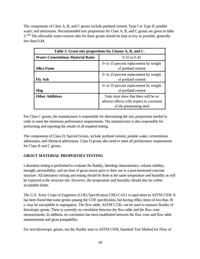
39
The components of Class A, B, and C grouts include portland cement, Type I or Type II; potablewater; and admixtures. Recommended mix proportions for Class A, B, and C grouts are given in table3.(20) The allowable water-cement ratio for these grouts should be kept as low as possible, generallyless than 0.44.
Table 3. Grout mix proportions for Classes A, B, and C.
Water-Cementitious Material Ratio 0.35 to 0.45
Silica Fume0- to 15-percent replacement by weight
of portland cement
Fly Ash0- to 25-percent replacement by weight
of portland cement
Slag0- to 55-percent replacement by weight
of portland cement
Other Additives Tests must show that there will be noadverse effects with respect to corrosion
of the prestressing steel
For Class C grouts, the manufacturer is responsible for determining the mix proportions needed inorder to meet the minimum performance requirements. The manufacturer is also responsible forperforming and reporting the results of all required testing.
The components of Class D, Special Grouts, include portland cement, potable water, cementitiousadmixtures, and chemical admixtures. Class D grouts also need to meet all performance requirementsfor Class B and C grouts.
GROUT MATERIAL PROPERTIES TESTING
Laboratory testing is performed to evaluate the fluidity, bleeding characteristics, volume stability,strength, permeability, and set time of grout mixes prior to their use in a post-tensioned concretestructure. All laboratory mixing and testing should be done at the same temperature and humidity as willbe expected at the structure site. However, the temperature and humidity should also be withinacceptable limits.
The U.S. Army Corps of Engineers (COE) Specification CRD-C-611 is equivalent to ASTM C939. Ithas been found that some grouts passing the COE specification, but having efflux times of less than 30s, may be susceptible to segregation. The flow table, ASTM C230, can be used to measure fluidity ofthixotropic grouts. There is currently no correlation between the flow table and the flow conemeasurements. In addition, no correlation has been established between the flow cone and flow tablemeasurements and grout pumpability.
For non-thixotropic grouts, use the fluidity tests in ASTM C939, Standard Test Method for Flow of
40
Grout for Preplaced-Aggregate Concrete (Flow Cone Method). The efflux time immediately afterthorough mixing should be between 11 and 20 s. After the grout has rested for 30 min without agitation,the efflux time should not be more than 30 s. Remix the grout for 30 s prior to the final flowmeasurement.
For thixotropic grouts, use a modified version of ASTM C939. Thixotropic grouts should not be testedby the flow cone method. In the modified C939 test, the flow cone is completely filled with grout andthe efflux time is the time taken to fill a 1-L container placed under the cone orifice. The efflux timeimmediately after thorough mixing should be between 11 and 20 s. After the grout has rested for 30 minwithout agitation, the efflux time should not be more than 30 s. Remix the grout for 30 s prior to the finalflow measurement.
Other tests for the pumpability of thixotropic grouts are the pressurized flow method that is described inReport No. FHWA-RD-92-095, Performance of Grouts for Post-Tensioned Bridge Structures.(23)
In the pressurized flow method, an orifice plate is placed in the bottom cap of a cylindrical brasscontainer. The time between the opening of the orifice until the first break in the continuous flow ofgrout is measured and compared with an acceptance criteria. For pressure-grouting operations, theinitial flow and the flow 30 min after mixing the grout, as determined using the test method described inReport No. FHWA-RD-90-102, Grouting Technology for Bonded Tendons in Post-TensionedBridge Structures, have an acceptable range of 10 to 15 s.(22)
Two bleed tests are used to determine the bleeding characteristics of grout. They are the Wick InducedBleed Test and the Pressure Bleed Test. The Wick Induced Bleed Test is a modification of ASTMC940 and should be performed for Class B, C, and D grouts. The maximum permissible bleed after 4 his 0 percent. The Pressure Bleed Test requires the use of the Gelman Pressure Filtration Funnel todetermine the bleeding characteristics of grouts used in pressure grouting for all four grout classes. ForClass A, B, and C grouts, bleeding should be less than 2 percent. For Class D grouts, bleeding shouldbe less than 1 percent. The grout should reabsorb water during the 24 h after mixing.
The volume change testing of grout should be performed according to ASTM C1090, Standard TestMethod for Measuring Changes in the Height of Cylindrical Specimens From Hydraulic-Cement Grout.The total volume change of the grout should be between 0.0 and 0.3 percent at 28 days. The expansionand shrinkage tests described in Report No. FHWA-RD-92-095 may also be performed whenspecified.
Compressive strength of the grout is determined using ASTM C942, Standard Test Method forCompressive Strength of Grouts for Preplaced-Aggregate Concrete in the Laboratory. Thecompressive strength of restrained cubes should be at least 21 MPa (3000 lb/in2) at 7 days and 35MPa (5000 lb/in2) at 28 days.
Permeability of the grout as determined by ASTM C1202, Standard Test Method for ElectricalIndication of Concrete’s Ability to Resist Chloride Ion Penetration, should be less than 3000 coulombsafter 6 h when tested at 30V and when testing the grout at 28 days.

41
The setting time as determined by ASTM C953, Standard Test Method for Time of Setting of Groutsfor Preplaced-Aggregate Concrete in the Laboratory, should be greater than 3 h and less than 12 h.
The acid-soluble chloride ion content in the grout as determined by ASTM C1152, Standard TestMethod for Acid-Soluble Chloride in Mortar and Concrete, should be less than or equal to 0.08percent by weight of portland cement. The acid-soluble chloride ion content in dry mix ingredients asdetermined by ASTM C114, Standard Test Methods for Chemical Analysis of Hydraulic Cement,should be less than or equal to 0.08 percent. One should not intentionally add chlorides to the groutmix.
Corrosion tests may be required by either the engineer or the contract documents. When a corrosioninhibitor is used, the Accelerated Corrosion Test (ACT) procedure described in Report No. FHWA-RD-91-092, Improved Grouts for Bonded Tendons in Post-Tensioned Bridge Structures, shouldbe performed.
SUITABILITY AND ACCEPTANCE TESTING
Suitability testing assesses the materials prior to their use. Acceptance and production testing evaluatesthe actual materials being used and whether or not they meet performance requirements. Field testinguses the same testing procedures as in laboratory testing. A production test frequency recommended bythe Post Tensioning Institute and the minimum testing requirements for suitability and acceptance testingproposed by the Concrete Society in the United Kingdom are summarized in table 4.(19-20) The PostTensioning Institute recommends which production tests should be performed based on the class of thegrout:
< Class A grouts – Bleed, strength, and fluidity tests.< Classes B and D, and thixotropic grouts – Bleed, volume change, strength, and fluidity tests.< Class C grouts – Fluidity.

42
Table 4. Minimum testing requirements.
Test Grout Property Concrete Society, United Kingdom Post Tensioning Institute, United States
Suitability Fluidity Sampled immediately after mixing, one test.Common grout: after estimated time to groutduct or minimum of 30 min.Special grout: after 90 min.Two tests averaged (both cases).
BleedVolume ChangeStrength
Each sampled immediately after mixing, three tests averaged.
ProductionAcceptance
Bleed Two tests per day, one sample taken fromgrout after flow through duct, at the endanchorage outlet, and the other from mixer.
Two tests per 1.5 m3 (2 ydOne sample taken at the mixer and one at theduct outlet when the grout at the outlet hassatisfactory fluidity.
Volume Change Two tests per day, one sample taken fromgrout after flow through duct, at the endanchorage outlet, and the other from mixer.
One test per day or per each 1.5 mgrout.
Strength Two tests per day, one sample taken fromgrout after flow through duct, at the endanchorage outlet, and the other from mixer.
A minimum of one strength test per 1.5 myd3) of grout.
Fluidity One test immediately after mixing, onesample from mixer.One test after flow through duct, one samplefrom each anchorage outlet.One test on completion of the grout job, onesample from mixer.
A minimum of one test per 2 h of groutingoperations or per 1.5 m

43
TEST METHODS FOR BONDED POST-TENSIONED CONCRETE
Prestressed concrete structures – pretensioned and post-tensioned – rely on the integrity of high-strength bars and strands for their primary safe load-carrying capability. The deterioration and ultimatefailure of one or more of these high-strength bars and strands could lead to the catastrophic failure ofpart or all of a structure. In post-tensioned structures, the prestressing tendons are normally enclosed inducts. It is desirable to have these tendons fully grouted as a corrosion-protection measure. If they arenot fully grouted (i.e., voids are present), moisture and aggressive chemicals could penetrate the duct,resulting in corrosion of the prestressing steel.
The test methods should be able to demonstrate that the structure was built according to specificationsand the tendons are fully grouted and no voids are present. Testing should preferably be done beforeacceptance to ensure that a durable structure was constructed. Testing can be done later in the servicelife of the structure to evaluate its long-term performance.
TESTS BEFORE AND DURING GROUTING
Tests performed during the initial stage of the construction of a bonded post-tensioned concretestructure have the most potential for preventing the formation of voids. Perform a pressure test toevaluate the sealing of the duct system before grouting. Perform a grout stiffness test during grouting. Inthis test, apply pressure to the grout in the duct while it is still in a plastic state and measure its response.This test is based on the principle that any gas in the grout will compress and the grout will not. Itsstiffness, a "spongy" response, could then indicate the presence of voids (trapped air). If inadequategrouting is detected (voids), stop grouting and flush the ducts or make adjustments to the groutingoperation and then continue. The "Spongeometer" Testing Device has been able to detect voids in full-scale ducts 60 m (197 ft) from where the measurement was taken.(19) However, entrained air couldinfluence the results and there still remains some uncertainty regarding its accuracy and reliability. Theequipment is still under development and should not yet be used for acceptance testing. A pressure testdone after concreting could be used to determine if any major damage has occurred during concretingand to evaluate the duct in its final condition. This more closely approximates actual service conditions.
TESTS FOR VOIDS IN DUCT – HARDENED GROUT
Several different methods of evaluating the extent of grouting in post-tensioning ducts have beendeveloped over the years.(24) Although it is more difficult to correct defects after the grout hashardened, an evaluation at this time can reveal any future potential corrosion problems due to thepresence of voids in the ducts. At this point, the bridge owner can decide if corrective measures areneeded.
The pressure method is used to check for small voids in locations not accessible by other methods. Apathway to the void is needed – a vent pipe, tube, or drilled hole. However, the likely location of thevoids needs to be known. Holes should not routinely be drilled as a method for searching for voids. Thepressure method requires specialized equipment. Although the hole can be used to re-grout any

44
detected voids, vacuum-grouting is needed to effectively fill these small voids.
Radiography uses gamma rays or x-rays to detect voids in the ducts. This test shows changes in densitythat are easy to see and understand. It can be used in concrete sections up to 800 mm (31.5 in) thick.Most equipment used for radiography requires the development of film. New versions now providereal-time images. The equipment is expensive. Radiography is also time-consuming and requires specialsafety considerations due to the high-energy output. It is not practical for very thick sections thatcontain heavy reinforcement and overlapping ducts.
Impulse radar is cheaper and safer. Access from only one side of the section being evaluated is needed.It can be used on thicker sections. The results, however, are less clear and some interpretation isrequired. It is also currently not precise enough to detect voids inside post-tensioning ducts.
The drilling and monitoring of the air flow method is a destructive method. There is a chance that theprestressing steel may be damaged or cut. The drilled hole, even after being filled, becomes an avenuefor future corrosion. Since the holes are drilled at suspected locations, one needs to know where totest.
The boroscope method is also a destructive method. A fiber-optic cable is used to view the inside ofthe post-tensioning duct. The test is performed at the locations of suspected voids. It typically uses acamera to record the images. It has the same disadvantages as the drilling and monitoring of the air flowmethod.
A recent development in the nondestructive evaluation of concrete structures that has good potential forapplication to concrete bridge structures is the impact-echo (IE) method.(25) It has been successfullyused to detect honeycombing and delaminations in the laboratory and in the field.
A mechanical impactor is applied to the concrete surface that introduces a transient stress pulse into theconcrete member. The stress pulse propagates into the member along spherical wavefronts. Dilatational(or compression) waves (P-waves) are parallel to the direction of propagation. Distortional (or shear)waves (S-waves) are perpendicular to the direction of propagation. There are also surface waves,referred to as Rayleigh waves (R-waves), that travel along the surface away from the impact point. Theamplitude of these waves decreases exponentially with depth into the member.
The P- and S-waves travel through the material and are reflected back by internal or external interfaces(i.e., internal defects or external boundaries). When the reflected waves arrive back at the surface pointwhere initial impact was generated, the resulting surface particle displacement is converted into anelectrical voltage by a receiving transducer. When this transducer is placed close to the impact point, P-wave arrivals dominate the displacement. In order to evaluate the displacement waveform, the traveltime (Ät) between pulse initiation and the arrival of the first reflected P-wave is determined. When theP-wave propagation velocity (C1) is known, the distance to the reflecting interface (d) can becalculated.

45
fC
d01
2 =
d Cf
= 1
02
The time-domain data interpretation is both time-consuming and tedious. A more effective approach isto perform a frequency analysis on the displacement waveform. This involves the construction of thefrequency spectrum time-domain data versus amplitude plot. As the stress pulse propagates betweenthe top surface and the internal or boundary interfaces, it produces a characteristic displacement eachtime it arrives at the top surface. This displacement is periodic and can be recorded as a waveform witha period (t), a travel path (2d), and a frequency (f0). The frequency is given by the following:
With a known velocity and frequency, either the slab thickness or the distance to an internal interface(defect) can be calculated using:
The P-wave propagation velocity is measured experimentally using a simple calibration method. TheFast Fourier Transformation (FFT) algorithm is then used to obtain the frequency content of therecorded waveform.
An impact-echo method consists of three major elements – an impact source, a displacementtransducer, and a data-acquisition system. Loading durations range from 10 to 55 ms and depend onthe size of the steel ball. The impact source is a small steel ball dropped on the concrete surface orapplied using a spring-loaded impactor. The transducer is normally a displacement sensor that is free ofstrong characteristic resonances, especially in the frequency range used in impact-echo testing. Thedata-acquisition system should be capable of performing waveform analysis in both the time andfrequency domains.
The impact duration affects both the propagating waves wavelength and the size of the flaws ordiscontinuities that can be detected. Only flaws with lateral dimensions greater than the wavelength canbe detected. Therefore, it is important to apply an impact load of an appropriate duration in order todetect the desired flaw sizes. While shorter contact times can detect smaller flaws, the ability of a stresswave to penetrate concrete is reduced as the contact time decreases.
Studies have shown that with the impact-echo method, it is possible to detect and examine the extent ofvoids in post-tensioning ducts. It may also detect honeycombing, delaminations, voids, and low-qualityconcrete. The studies performed included laboratory and field evaluations.
A series of laboratory tests were performed to determine the effects of various parameters on thereceiving signals: planar flaws, grouted and ungrouted metal ducts, grouted and ungrouted polyvinyl

46
chloride ducts, honeycombing, and various steel reinforcing bar sizes. Concrete samples with knowndefects were fabricated and tested.
A field evaluation of the grouting status of the ducts in an existing post-tensioned concrete box-girderbridge in Milwaukee, Wisconsin, was performed.(24) The bridge is a two-span continuous structure with24.38-m (80-ft) spans. Each girder web contains two post-tensioning tendons. The upper tendonconsists of 31 seven-wire strands and the lower tendon consists of 19 seven-wire strands. The fieldresults agreed with the laboratory experimental and numerical studies.
In another field study, 14 post-tensioning ducts were tested using the impact-echo method.(26) Thelocation of the structure was not reported. Of these ducts, 11 were found to be fully grouted and 3were found to contain voids. The results were verified by opening and visually inspecting the ducts; theresults were accurate. The impact-echo method was able to determine the extent of the grouting, eventhough test complications were present – cracking along the centerline of the duct, the presence ofmultiple ducts in close proximity to each other, and a varying concrete cover thickness.

47
CORROSION INHIBITORS
Corrosion inhibitors are chemical admixtures added to portland cement concrete mixes during batching– usually in very small concentrations – as a corrosion-protection measure. Corrosion inhibitors are aviable corrosion-protection measure for the long-term durability of both conventionally reinforced andprestressed concrete bridge structures. When used as part of a multiple-strategy corrosion-protectionsystem, they are promising materials to delay the onset of reinforcing and prestressing steel corrosion.
Inhibitors are often used in combination with low-permeability concrete and usually they have the effectof increasing the threshold chloride concentration needed to initiate corrosion. Inhibitors play animportant role in protecting uncoated high-strength steel strands used in prestressed concrete bridgemembers and stays used in cable-stayed bridges. They are also used in cementitious grouts for filling theducts of bonded post-tensioned bridges. Inhibitors may also reduce the subsequent corrosion rate afterthe initiation of corrosion, which ultimately leads to less corrosion-induced concrete deterioration.
There are three major concerns regarding the use of corrosion inhibitors. The first one is the long-termstability and performance of the inhibitor. The second is the inhibitor’s effect on corrosion propagationafter corrosion initiation. The third is the inhibitor’s effect on the concrete’s physical properties over theservice life of the structure.
In order for a corrosion inhibitor to be an effective long-term corrosion-protection measure, it needs tobe able to maintain long-term stability. It should be chemically intact and physically present (not leachingor evaporating) to retain its effectiveness.
Inhibitors may have an effect on the corrosion process after corrosion initiation. An insufficient dosagewill have a negative impact on corrosion progression. Some inhibitors will have an effect on chloridetransport and can reduce the rate of chloride ion migration.
Inhibitors should not have any negative effects on the concrete properties. The use of an inhibitor shouldnot cause an undue increase in the amount of any concrete cracking. Some inhibitors decrease theconcrete resistivity, which has a tendency to increase the corrosion rate. This effect is offset due to theinhibition provided by a suitable corrosion inhibitor.
Corrosion inhibitors are either inorganic or organic and, in general, are classified based on theirprotection mechanism. They can protect by affecting the anodic reaction, the cathodic reaction, or bothreactions (mixed). An active type of inhibitor (anodic) facilitates the formation of an oxide film on thesurface of the steel reinforcing bars. Passive systems protect by reducing the rate of chloride ionmigration. Calcium nitrite is an inorganic inhibitor. It protects the steel reinforcing bars throughoxidation-reduction reactions at the steel surface. Organic inhibitors consist primarily of amines andesters. They form a protective film on the surface of steel reinforcing bars and sometimes delay thearrival of chloride ions at the steel reinforcing bars.

48
There are four major commercially available corrosion inhibitors:
< DCI (Darex Corrosion Inhibitor) and DCI-S.< Rheocrete 222 and Rheocrete 222+.< Armatec 2000, Ferrogard 901, and MCI 2000.< Catexol 1000 Cl.
DCI (Darex Corrosion Inhibitor) and DCI-S(27)
DCI (calcium nitrite) is an inorganic corrosion-inhibiting concrete admixture. It has been commerciallyavailable since 1978 and up to now it was only marketed by W.R. Grace and Company. Recently,Master Builders, Inc. also started marketing a calcium nitrite inhibitor similar to DCI. DCI hasapproximately a 30-percent concentration of calcium nitrite. DCI-S is the same as DCI, but alsoincludes a set retarder. When silica fume is used in combination with calcium nitrite, the silica fumereduces the rate of chloride ion penetration (migration) and the calcium nitrite increases the threshold forcorrosion initiation. Calcium nitrite reduces the resistivity values of concrete, but the addition of silicafume offsets this reduction and, in fact, there is a net gain in resistivity.
DCI is an anodic type of inhibitor (active) and functions by passivating the anode. The oxidation-reduction protection mechanism is electro-chemical in nature and, as a result, its effectiveness isunderstandable and quantitatively measurable. The chloride and nitrite ions are involved in simultaneous,complicated, competing reactions at the surface of the steel reinforcing bars: corrosion vs. passivation.Chloride ions accelerate corrosion through the formation of Fe++ ions. Nitrite ions inhibit corrosionthrough the formation of passive iron oxide (Fe2O3).
Calcium nitrite inhibits or interferes with the removal of Fe++ ions through the following reaction:
2Fe++ + 2OH- + 2NO2- 6 2NO8 + Fe2O3 + H2O
The relative rates of the two processes (corrosion and passivation) are unknown.
This prevents further corrosion. However, nitrite ions are reduced to nitric oxide gas. This reduces thenitrite concentration in the concrete in the immediate vicinity of the reinforcing steel. As the chloride ioncontent increases, the ability to maintain passivity is reduced (with a constant amount of nitrite).
DCI appears to be primarily effective because it does not allow the development of large electricalpotentials between areas that otherwise would be anodic and cathodic – adjacent steel areas in the topmat of reinforcing steel bars and between top and bottom mats of reinforcing steel bars in a bridgedeck. Electrical potentials are maintained at similar values that are also at or near the passive range.Large electrical potential between otherwise anodic and cathodic areas allows the flow of a corrosioncurrent and subsequent dissolution of iron in the top mat.
The relative concentrations of nitrite and chloride ions are important. For a low Cl-/NO2- ratio (less than

49
1), the potentially anodic rebar is passivated. For a high Cl-/NO2- ratio, the eventual corrosion of the
steel reinforcing bar is certain.
In general, the corrosion rate increases as the Cl-/NO2- ratio increases. A long-term study on the
effectiveness of calcium nitrite as a corrosion inhibitor was performed by the Federal HighwayAdministration.(28) Earlier results showed that with a Cl-/NO2
- ratio up to 1.25, the corrosion rate wasreduced by at least an order of magnitude. In other words, it would take more than 10 years toconsume an equal amount of iron as in 1 year for a slab with an equal chloride ion content, uncoatedsteel, and no calcium nitrite.
Subsequent data showed that in order for calcium nitrite to be an effective corrosion inhibitor, the Cl-
/NO2- ratio should be less than or equal to 1.1. For ratios between 0.3 and 1.1, the corrosion rate is
reduced by a factor of approximately 10. When the Cl-/NO2- ratio was above 1.1, the corrosion rates
were reduced by a factor of about 2 and test slabs had cracks, major rust stains, and hollow andspalled areas.
The amount of calcium nitrite that should be added to the concrete during mixing depends on expectedchloride ion concentration at the rebar for the desired corrosion-free service life. There is no significantbenefit in using calcium nitrite as an inhibitor for Cl-/NO2
- ratios greater than 1. Therefore, therecommended dosage is that which will yield a Cl-/NO2
- ratio at the rebar level that is less than or equalto 1 during the service life of the structure. This conclusion is based on research where the chloride ionswere mixed into the fresh concrete along with DCI, which is not the normal practice in the field.Therefore, the inhibitor has a better chance of performing under normal circumstances when chlorideions diffuse through the concrete. With time, the chloride ion level is the expected accumulative contentat the surface of the steel reinforcing bars due to deicer applications or marine exposure. Long-termstability is an issue as the inhibitor is not needed until a sufficient amount of chloride ions reach the steeland corrosion is initiated. Recommended dosage rates for different expected chloride ion contents for acorrosion-free service life are shown in table 5.(29)
Table 5. Calcium nitrite dosage rates.
Calcium Nitrite [L/m3 (gal/yd3)]
Chloride Ion Content[kg/m3 (lb/yd3)]
10 (2) 3.6 (6.0)
15 (3) 5.9 (9.9)
20 (4) 7.7 (13.0)
25 (5) 8.9 (15.0)
30 (6) 9.5 (16.0)

50
Rheocrete 222 and Rheocrete 222+(27)
Rheocrete 222+ is an organic corrosion-inhibiting concrete admixture. It is manufactured and marketedby Master Builders, Inc. It is an improved formulation of Rheocrete 222 and contains amines and estersin a water medium. Rheocrete 222 is a combination inhibitor, both anodic and cathodic (passive-activemixed type). It protects the steel reinforcing bars in two ways: First, it forms a corrosion-resistantorganic film that is adsorbed on the steel surface. Secondly, it also coats the pores of the concretematrix, which slows the migration of chloride ions.
Both Rheocrete 222 and Rheocrete 222+ have not been available for a very long time, compared tocalcium nitrite. As a result, there is less published data on their performance. Rheocrete 222 has beenused in a number of parking garages, and in a few bridges and marine structures. The recommendeddosage rate is 5 L/m3 (1 gal/yd3). It is typically added to the concrete batch water. The dosage rate isnot adjusted for the anticipated corrosiveness of the expected service environment.
Armatec 2000, Ferrogard 901, and MCI 2000(27,30)
These inhibitors are a blend of surfactants and amine salts [specifically dimethylethanolamine (DMEA),also referred to as alkanolamines or amino-alcohols (AMA)] in a water medium. Armatec 2000 andMCI 2000 are manufactured and marketed by Cortec Corporation. Armatec is reported to have aslightly different formulation from MCI. Ferrogard 901 is manufactured and marketed by SikaCorporation.
According to the manufacturers, they protect the steel reinforcing bars by forming a continuous mono-molecular film on the steel surface and they cover both the anodic and cathodic sites (mixed type). Thisfilm consists of an adsorbed layer of amino-alcohol that leads to the formation of insoluble iron oxidecomplexes. These stabilize the oxide surface and inhibit further corrosion. The film is typically 10-8 mthick and also acts as a barrier to aggressive ions migrating through the concrete. It has been reportedthat incoming chloride ions on the steel surface can be displaced by amino alcohols. The recommendeddosage rate for Ferrogard 901 is 10 L/m3 (2 gal/yd3). The dosage is not adjusted for the corrosivenessof the anticipated service environment.
Catexol 1000 Cl(30)
This inhibitor is a water-based formulation of amine derivatives. Catexol 1000 Cl is manufactured andmarketed by the Axim Concrete Technologies, Inc. The manufacture claims that protection is providedby formation of a protective barrier. This barrier reportedly stabilizes the passive iron oxide layer. Thisinhibitor appears to exhibit the characteristics of an organic film-forming inhibitor, as well as those of anitrite-based inhibitor.

51
FIELD PERFORMANCE OF EPOXY-COATED REINFORCING STEEL
The primary cause of the deterioration of reinforced concrete structures is the corrosion of steelreinforcing bars due to chlorides. Epoxy-coated reinforcing steel (ECR) was developed andimplemented in the mid-1970's to minimize concrete deterioration caused by corrosion of thereinforcing steel and to extend the useful life of highway structures. The epoxy coating is a barriersystem intended to prevent moisture and chlorides from reaching the surface of the reinforcing steel andto electrically insulate the steel to minimize the flow of corrosion current.
Epoxy coatings (sometimes referred to as powders or fusion-bonded coatings) are 100-percent solid,dry powders. These dry epoxy powders are electrostatically sprayed over cleaned and preheated steelreinforcing bars. The coatings achieve their toughness and adhesion to the steel substrate as a result of achemical reaction initiated by heat. These epoxy powders are thermosetting materials and their physicalproperties do not change readily with changes in temperature.
The coating process consists of several steps:(31)
1. Steel reinforcing bars between 6.0 and 18.3 m (20 and 60 ft) in length and of various diametersmove along powered rollers at speeds of 6 m/min to more than 15 m/min (20 to 50 ft/min).Typically, eight bars move parallel to each other on a set of rollers.
2. The bars are blast-cleaned with grit or shot in a grit-blasting booth to a near-white blast asspecified in the Society for Protective Coatings Specification SSPC-SP-10.
3. In some plants, the bars pass through a pretreatment application unit where a pretreatmentsolution is applied, the excess is removed, and the bars are dried prior to leaving the unit. Todate, there is not enough data to verify the usefulness of this process.
4. The bars are then heated very rapidly (within 1 to 3 s) to 246EC (475EF) as they pass throughan induction coil.
5. As the bars enter the spray booth, epoxy powder is electrostatically sprayed onto the bars bystationary automatic spray guns. When the powder hits the hot bars, it melts and becomes fluidto form a smooth coating.
6. After the bars leave the powder-coating booth, the ambient air begins to cool them. The coatingcontinues to cure due to the heat retained within the bars. The powder coating is formulated tobe tough enough not to be marked by the rollers while it is curing. The line speed is adjusted sothat the coating has enough time to fully cure.
7. The bars are then either sprayed with cold water or completely immersed in water to cool thebars so that they can be handled.
52
8. When the cooled bars reach the end of the line, they are automatically lifted off of the rollersand stacked.
Numerous studies on the corrosion performance of ECR have been conducted. The initial study wasfunded by the Federal Highway Administration (FHWA) and performed by the National Bureau ofStandards (now called the National Institute of Standards and Technology). The results were containedin the 1974 FHWA Report, Non-Metallic Coatings for Concrete Reinforcing Bars (Report No.FHWA-RD-74-018). The optimum epoxy coating thickness was found to be 0.18 ±0.05 mm whenconsidering corrosion protection, bond strength, creep characteristics, and flexibility.(32) The coatingprocess was adapted from the method used for epoxy coating small-diameter pipes used by utilitycompanies and the petroleum industry. Epoxy-coated reinforcing bars for a bridge deck were first usedin 1973 in Pennsylvania. The bars were coated in a pipe-coating facility. The main problems influencingthe corrosion performance at the time were considered to be damage to the coating duringtransportation and handling, and the process of bending the bars, which cracks the coating.
In the 1980's, FHWA initiated outdoor exposure tests. The purpose was to determine the benefits ofcoating both mats of reinforcing steel in bridge decks. The study intentionally used bars with excessiveholidays, damage, and bare areas. Three different combinations for the top and bottom mats ofreinforcing steel were investigated: black-black, epoxy-epoxy, and epoxy-black. Even poor-qualityepoxy-coated reinforcing steel was found to have reduced corrosion by 11.5 times when only the topmat was coated and by 41 times when both mats were coated. The reduced corrosion rate wasattributed to the high electrical resistance of the coating and a reduced cathodic area.(33)
As a result of observed corrosion in the Florida Keys bridges, the Florida Department ofTransportation (DOT) initiated several studies to determine the extent and cause of the corrosion. Thesubstructure showed signs of corrosion in only 5 to 7 years after construction in the area 0.6 to 2.4 m(2 to 8 ft) above the mean high-water mark (splash zone). The corrosion affected both straight and bentbars. The early studies showed that corrosion was aggravated by bending, coating defects, andcorrosion macrocells. Coating disbondment could be due to exposure to saltwater, a mild level ofcathodic polarization, and also to the anodic conditions present while the bar was corroding. Coatingdisbondment could also occur in chloride-free concrete. In an investigation of 30 bridges, most did notshow visible signs of corrosion. The coating thicknesses were generally within the specification limits ineffect at the time of construction. The median amount of coating damage was found to be 0.4 percent ofthe bar surface. There was a reduction in adhesion in the extracted coated steel specimens from most ofthe bridges compared to the coated steel at the time of construction. No evidence of rebar corrosionwas found except for the Keys bridges. It appears that a sequence of events may have led to thepremature corrosion in the Keys bridges.
PERFORMANCE OF EPOXY-COATED REBARS IN BRIDGE DECKS
In response to reports of poor performance of ECR, most notably in the substructure units in theFlorida Keys, FHWA recommended that States evaluate the performance of ECR in existing bridgedecks. This is because FHWA supported the use of ECR in bridge decks alone; however, due to its

53
good performance, States started to use ECR in reinforced concrete bridge substructures. As a result,several States initiated investigations and prepared reports documenting their findings and results.
The FHWA report, Performance of Epoxy-Coated Rebars in Bridge Decks (Report No. FHWA-RD-96-092), summarizes the results of those investigations, as well as others that have been performedby highway agencies in the United States and Canada, by academia, and by the Canadian StrategicHighway Research Program (C-SHRP).(34) A total of 92 bridge decks, 2 bridge barrier walls, and 1noise barrier wall located in California, Indiana, Kansas, Michigan, Minnesota, New York, Ohio,Pennsylvania, Virginia, West Virginia, and Wisconsin, and the provinces of Alberta, Nova Scotia, andOntario were evaluated. At the time of the investigations, the ECR had been in service for 3 to 20years. For the majority of the bridges, the ECR had been in service for about 10 years.
The investigations typically included field and laboratory evaluation phases. The field evaluation phasesconsisted of some or all of the following:
< Visual examination of the deck concrete for cracking, spalling, and patches.< Chain drag to locate areas of delamination.< Use of a pachometer to determine the amount of concrete cover and to locate the top mat of
reinforcing steel for concrete coring.< Drilling for concrete powder samples for chloride content.< Concrete coring to evaluate the quality of the concrete and for chloride content.< Overall deck condition ratings.< Half-cell potentials.< Resistivity readings.< Three-electrode linear polarization resistances to determine the rate of corrosion.
The laboratory evaluation phases consisted of some or all of the following:
< Visual examination of the concrete in the extracted cores.< Measurement of concrete cover over the ECR in the extracted cores.< Evaluation of the extracted ECR segments.< Measurement of the epoxy-coating thickness on the extracted ECR segments.< Determination of total or water-soluble chloride ion content in the concrete using the extracted
cores or the concrete powder samples.< Permeability of the concrete in the extracted cores.< Determination of pH in the concrete adjacent to the ECR in the extracted cores.< Compressive strength of the concrete in the extracted cores.< Unit weight of concrete using the extracted cores.
The summary of the findings and discussion are based on the results of field evaluations of the structuresand the laboratory evaluations of concrete cores taken from the various structures as documented inreports by the various departments of transportation. A total of 92 bridge decks, 2 bridge barrier walls(parapets), and 1 noise barrier wall were evaluated in the field for cracking, delaminations, and spalls.

54
Overall, the structures were generally found to be in good condition. Concrete deterioration wasgenerally in isolated areas and often not related to corrosion of the ECR.
The extent of deck cracking ranged from very little or none, to extensive. Cracking, when present, wasgenerally transverse in nature. Deck cracking was not thought to be the result of any corrosion of ECR.The cracking in the bridge barrier walls consisted of scattered pattern cracking with some verticalcracks. The noise barrier wall consists of precast concrete panels and the panels that are closest to theroadway surface were cracked the most and exhibited rust staining and spalling.
Very few spalls or delaminations were found in the bridge decks. Delaminations were detected in only10 of the bridge decks. Approximately half of these delaminations were small (0.1 m2 (1 ft2) in size).The others varied from 0.3 m2 (3 ft2) to approximately 2.8 m2 (30 ft2) in size. Several other detecteddelaminations were associated with expansion devices (uncoated metal) and were not due to anycorrosion of ECR.
The depth of concrete cover over the top rebar was measured in each of the cores. Average concretecover was generally found to be adequate, at least 51 mm (2 in). However, some instances ofinadequate concrete cover were found.
Most investigators determined the total chloride (acid-soluble) content at the rebar level or chlorideprofiles. The concrete samples were either obtained from the concrete cores or from holes drilled intothe concrete. In most cases the average chloride concentrations at the rebar level were at or above thethreshold level to initiate corrosion in black steel.
The total chloride concentration at the rebar level was determined in 40 bridge decks. The averagechloride concentration of all these decks was 2.2 kg/m3 (3.7 lb/yd3). The chloride concentration wasgreater than or equal to 0.6 kg/m3 (1.0 lb/yd3) in 33 (83 percent) of these decks and was greater thanor equal to 1.2 kg/m3 (2.0 lb/yd3) in 24 (60 percent) of these decks. In addition, the chlorideconcentration was greater than or equal to 3.0 kg/m3 (5.0 lb/yd3) in 11 (28 percent) decks, with thehighest concentration being 6.8 kg/m3 (11.5 lb/yd3).
The water-soluble chloride concentration at the rebar level was determined in 16 other bridge decks.The average chloride concentration of all these decks was 0.7 kg/m3 (1.1 lb/yd3). The chlorideconcentration was greater than or equal to 0.6 kg/m3 (1.0 lb/yd3) in five (31 percent) of these decksand was greater than or equal to 1.2 kg/m3 (2.0 lb/yd3) in two (13 percent) of these decks. None ofthese decks had chloride concentrations greater than 3.0 kg/m3 (5.0 lb/yd3), with the highestconcentration being 2.6 kg/m3 (4.3 lb/yd3).
Some of the ECR segments extracted from the cores were examined for visual defects in the coating(holidays), thickness of epoxy coating, and the blast profile on selected bars. Most, if not all, of thesegments that were examined contained holidays or bare areas. The thickness of the coatings wasgenerally within the limits specified at the time of construction. In most of the instances when the coatingthickness did not meet specifications, it exceeded the upper limit. The blast profiles that were evaluated
55
were found to have met applicable specifications.
The same ECR segments extracted from the cores were examined to determine the condition of thesteel surface under the coating. Approximately 212 different ECR segments were examined. This totaldoes not include ECR segments evaluated in the C-SHRP study from the five bridge decks and onebarrier wall that were previously evaluated by others. It also does not include ECR segments fromPennsylvania as that report did not indicate how many segments were examined. For the majority ofECR segments, no corrosion was present.
Approximately 202 ECR segments were extracted from bridge decks. Out of these segments, 162 (81percent) did not have any corrosion present. For some of the remaining segments that exhibitedevidence of corrosion, the corrosion may have been present at the time of construction since chloridecontents at the time of the evaluation were below the initiation threshold. Only four ECR segments (2percent) were reported as having experienced significant corrosion. The areas of corrosion weretypically at locations of visible holidays or bare areas. The more heavily corroded ECR segments werealso from locations of relatively shallow concrete cover with high chloride concentrations.
Ten ECR segments were extracted from the barrier and noise walls. Out of these segments, eight (80percent) did not have any corrosion present. Only one ECR segment (10 percent) was reported ashaving experienced significant corrosion. The areas of corrosion were typically at locations of visibleholidays or bare areas. The more heavily corroded ECR segment was also from a location of veryshallow concrete cover, highly permeable concrete, and with high chloride concentration.
Some ECR segments extracted from the cores were also examined for any coating disbondment. Theextent of coating disbondment varied and was found in both corroded and non-corroded areas. Visibleholidays were generally present on ECR segments that experienced coating disbondment. In mostcases, the coating was generally still bonded to the steel surface. California reported coating disbondment on 12 ECR segments (out of 32 total) in both corroded andnon-corroded areas. Except for one segment, visible holidays were present on all ECR segments thatexperienced coating disbondment. The extent of coating disbondment varied from 3 to 100 percent ofthe rebar surface, with six segments having coating disbondment of more than 75 percent of its surface.Indiana reported that no ECR segments showed any signs of debondment of the epoxy coating. Thecoatings were difficult to strip with a knife. Some segments were mechanically stripped of their coatingin order to examine the underside of the film. Michigan reported that the epoxy coatings on ECRsegments extracted from the experimental decks and with moist concrete were easily removed by handwith the use of a fingernail. Virginia reported that the epoxy coatings remained tightly bonded to thesteel and could only be removed with a knife.
The results of two separate investigations done in Ontario were reported. In the first investigation, twobarrier walls were evaluated. None of the ECR segments in one of the barrier walls showed evidenceof any coating disbondment. There was evidence of isolated locations in the second wall with poorbonding between the epoxy coating and the ribs of the rebars where the coating could be removed witha knife. However, the coating on the body of the bar could not be removed by a knife after scoring a
56
cross into the coating.
In a second investigation, ECR segments were extracted from 12 bridges in exposed concretecomponents – barrier walls, end dams, sidewalks, and decks built without waterproofing. Theextracted ECR segments were tested for adhesion of the epoxy coating to the steel surface. Of theECR segments extracted from structures built in 1979 and 1980, 27 percent had a well-adheredcoating that could not be lifted from the steel substrate. Of the ECR segments extracted from structuresbuilt between 1982 and 1985, 60 percent had a well-adhered coating. Of the ECR segments extractedfrom structures built in 1990, 88 percent had a well-adhered coating. It appears that adhesion of theepoxy coating decreases with time as ECR segments extracted from bridges with the longest service lifeexhibited the most adhesion loss.
In the C-SHRP study, the extent of coating disbondment was determined using the dry knife adhesiontest. Of the 44 tests performed on ECR segments from the 19 structures, 54 percent had a very well-bonded coating, 14 percent had a coating that was somewhat easy to remove, and 32 percent had acoating that was easy to remove or totally disbonded. The coatings on slightly more than half of theECR segments still had good adhesion.
The following conclusions are based on the results and findings from these evaluations of theperformance of ECR in bridge decks, bridge barrier walls (parapets), and a noise barrier wall:
< The overall condition of the bridge decks was considered to be good. Even though deckcracking was prevalent, it did not appear to be corrosion-related. Very few of the decks hadany delaminations and/or spalls. Most of the delamination was not associated with the ECR.The maximum extent of delamination reported was less than 1 percent of the deck area.However, the actual extent of delamination was not reported.
< A bridge in West Virginia had a total of approximately 3.7 m2 (40 ft2) of delaminated area outof a total deck area of 1653.6 m2 (17,800 ft2), approximately 0.25 percent of the deck area,after 19 years of service life. The largest of these delaminations was centered on a constructionjoint and was most likely not corrosion-related. Chloride contents are not available for this deckand the report does not indicate whether the delaminations were corrosion-induced. The Stateof West Virginia indicated in their report that based on their previous experience, a typical deckof the same design, but with black steel, would have more delaminations (5 to 20 percent of thedeck area is common).
< The chloride concentrations at the rebar level for most bridges were at or above the corrosionthreshold for black steel. However, the chloride levels in some others were still below thethreshold.
< Corrosion on the extracted ECR segments was determined to be minor in most of the extractedcores. No evidence of corrosion was found on 81 percent of the extracted ECR segments,even though chloride concentrations up to 3.8 kg/m3 (6.4 lb/yd3) were well above the chloride

57
threshold level for initiating corrosion in black steel.
< ECR did not appear to perform as well when the concrete was cracked as when the concretewas not cracked. There was more corrosion activity on ECR segments extracted from corestaken at locations where the deck was cracked. Even with high chloride concentrations up to7.6 kg/m3 (12.8 lb/yd3), no visible or negligible corrosion was found on ECR segmentsextracted from cores taken in uncracked locations. The cracks give both chlorides and moistureeasy and direct access to the ECR, which appears to accelerate the corrosion process.
< In California, corrosion on the extracted ECR segments was more severe at locations of heavycracking, shallow concrete cover (15 to 25 mm [0.6 to 1.0 in]), and high chlorideconcentrations (9.7 to 15.0 kg/m3 [16.4 to 25.3 lb/yd3]). Moisture/water and a high chloridecontent present at the rebar level for a considerable length of time are responsible for theobserved corrosion.
< The Ontario Ministry of Transportation reported that corrosion on the extracted ECR segmentswas more severe at a location of heavy cracking, shallow concrete cover (15 mm [0.58 in]),and a high chloride concentration (9.4 kg/m3 [15.8 lb/yd3]). This ECR segment was extractedfrom a noise barrier wall panel that had significant corrosion-induced concrete distress.Moisture/water and a high chloride concentration at the rebar level are once again responsiblefor the corrosion observed. The concrete in this barrier wall was also very permeable (21,293and 22,722 coulombs). A typical bridge deck does not have such a low concrete cover and/orhighly permeable concrete.
< Reduction in adhesion and softening occurred as a result of prolonged exposure to a moistenvironment. In California, a reduction in adhesion occurred at both corroded and non-corroded areas and was generally detected at visible holidays. In Indiana, the ECR segmentsshowed no signs of a reduction in coating adhesion. In Michigan, coatings on ECR segmentsextracted from moist concrete could easily be removed. In New York, coating deteriorationwas not found on any of the ECR segments. Tests performed in Ontario showed that adhesionof the epoxy coating to the steel substrate decreases with time. Approximately 54 percent ofthe ECR segments evaluated under the Canadian Strategic Highway Research Program (C-SHRP) still had good adhesion of the epoxy coating.
< The number of defects in the epoxy coating and the amount of disbondment influence theperformance of ECR. Many of the extracted ECR segments contained defects – holidays, bareareas, mashed areas, or a combination of one or more of these. In California, high chlorideconcentrations up to 4.6 kg/m3 (7.7 lb/yd3) did not initiate corrosion when there were nodefects (holidays) in the coating, indicating that undamaged epoxy coatings provide an adequatebarrier to chlorides. In Virginia, there were no indications of significant corrosion, even thoughthe initial condition of the coating was poor and numerous holidays and bare areas werepresent.

58
< A comparison of the performance of ECR in decks with only the top mat of reinforcing steelepoxy-coated, and decks with both the top and bottom mat of reinforcing steel epoxy-coated,suggests superior performance when both mats are epoxy-coated.
< The bridges evaluated in California were originally constructed with black steel. Based on thedates of original construction and first redecking, it appears that the use of black steel onlyprovided 10 to 12 years of service life. However, it is possible that there were othercontributing factors besides the use of black steel, including shallow cover and a lower qualityof concrete.
< The use of an adequate good-quality concrete cover, adequate inspection, finishing, and curingof the concrete, and the proper manufacturing and handling of ECR complement the use ofECR in providing effective corrosion protection for concrete bridge decks.
< ECR has provided effective corrosion protection for up to 20 years of service. Corrosion wasnot a significant problem in any of the decks evaluated. No signs of distress were found in thefirst bridge decks built with ECR. There was no evidence of any significant premature concretedeterioration that could be attributed to corrosion of the ECR. Some of the cores wereintentionally taken at locations representing a worst-case scenerio. Therefore, these cores maynot be representative or indicative of the overall performance that can be obtained from ECR.Little or no maintenance or repair work has been done on most of the decks.
As a result of renewed concerns about the effectiveness of ECR as a corrosion-protection measure, theState of Virginia performed another evaluation of three additional bridges in 1996. The results of thisevaluation are presented in a 1997 report entitled Field Investigation of the Corrosion ProtectionPerformance of Bridge Decks Constructed With Epoxy-Coated Reinforcing Steel in Virginia.(35)
The three bridge decks are located in a high deicer application area and are among the oldest bridgedecks built with ECR in Virginia. All three were constructed with ECR in the upper mat of reinforcingsteel and black steel in the lower mat of reinforcing steel. The decks were 17 years old at time of theinvestigation. The evaluation used the results of NCHRP Project 10-37B, A Protocol for theEvaluation of Existing Bridges Containing Epoxy-Coated Reinforcing Steel, which providesmeasurable performance indicators, investigative procedures and plans, and methods of analysis.
These are some comments on the results and findings of this evaluation of three additional bridge decksin Virginia:
< The same corrosion mechanism applies to substructures and bridge decks.< Coating disbondment occurs at a faster rate in lower quality concrete.< It takes longer for ECR bars in bridge decks to disbond compared to ECR bars in piles in
marine environments.< Epoxy coatings are expected to disbond in humid environments.< If sufficient chlorides reach the ECR before the coating disbonds, the epoxy coating provides
additional service life.
59
< Based on a statistical analysis of bridge deck service life, it is estimated that for 95 percent ofbridge decks in Virginia, the coating will disbond before chlorides reach the ECR and thecoating will not provide any additional service life.
< The authors conclude that ECR is not a cost-effective corrosion-protection measure for bridgedecks in Virginia.
However, the actual field performance and condition of the decks as reported (minimal cracking anddelamination, as well as no visual signs of corrosion-induced deterioration) does not seem to supportthis conclusion.
ECR, especially when used in bridge decks, has demonstrated excellent performance in resistingcorrosion and avoiding any corrosion-induced concrete deterioration. However, when used insubstructures, ECR has not performed as expected in a few bridges that were exposed to a severelycorrosive environment. ECR performs better than black bars and can extend the time to corrosion-induced deterioration in reinforced concrete structures. Since its introduction coincided with the use ofimproved concrete quality and increased concrete cover over the reinforcing steel, both of which alsoimpact the time to corrosion initiation, it may be too soon to tell how much ECR contributes toimproved performance. The factors that would accelerate ECR corrosion, such as damaged coating,poor concrete quality, low concrete cover, and severe exposure, all need to be addressed. In general,the conclusions on the performance of ECR as a corrosion-control measure vary from satisfactoryperformance in decks to poor performance in substructures exposed to marine environments.
The Ontario Ministry of Transportation has implemented several measures to address some of thesefactors. One is time limits on the storage of ECR bars – a 30-day maximum for unprotected bars and a120-day maximum total for on-site storage. Bars with more than 1-percent surface area damaged arerejected and repair is not allowed. For those bars that are accepted, any visually detected damage is tobe repaired. The use of plastic-coated concrete vibrators when consolidating the concrete is stronglyrecommended. Additional requirements for cathodic disbondment and salt-spray testing have beenimplemented.

60
CORROSION-RESISTANT REINFORCING BARS
Steel reinforcing bars are subject to various severe environments before being placed in concrete(during transportation, storage, and installation) and in service while embedded in the concrete. Coatedreinforcing bars are subject to abrasion or other damage during fabrication, transport, handling,installation, and concrete placement. During storage, reinforcing bars can be exposed to condensation,rain, deicing chemicals, and seawater. After the reinforcing bars are embedded in concrete, they areinitially exposed to a high pH and moist environment, which, over time, is changed to high and low pHareas, high chloride, and moist environment. The coatings need to be stable in all these environmentsand should not deteriorate.
Coating defects are a major factor in coating deterioration. Holidays and coating defects providechloride ions direct access to the steel surface and also reduce the overall electrical resistance and,hence, the durability of the coating. Typical coating defects are due to manufacturing, handling, bending,and abrasion, and are often found at bar marks. The typical specification limit is a maximum of 3.3holidays per meter (1.0 holidays per foot). Holiday counts are made using a 67.5V, 80,000-ohmholiday detector in accordance with ASTM G62. Additional new holidays may be introduced as aresult of the bending operation. Coating failure modes include crushing failure (cold flow), cracking, andholidays.
Coating thickness is covered by both AASHTO and ASTM specifications. Older specifications calledfor 90 percent of the coating thickness population to fall between 0.125 and 0.30 mm (5 and 12 mils).Present specifications call for 90 percent of the coating thickness population to fall between 0.175 and0.30 mm (7 and 12 mils). This results in a more stringent coating variability requirement than for theolder specifications using an assumed normal distribution of coating thickness. The coefficient ofvariation is a measure of the variability of coating thickness and is defined as the standard deviationdivided by the average. Low coefficients are an indication of uniform rates of coating application. Inorder to meet the 90-percent confidence limits under the older ASTM/AASHTO thicknessspecification of 0.125 to 0.30 mm (5 to 12 mils), a coefficient of variation of 25 percent was needed. Inorder to meet the 90-percent confidence limits under the newer ASTM/AASHTO thicknessspecification of 0.175 to 0.30 mm (7 to 12 mils), a coefficient of variation of less than 16 percent isneeded.
The maintenance of coating adhesion is a factor in the long-term effectiveness of a coating system as acorrosion-protection mechanism. Although a reduction in coating adhesion by itself may not necessarilyresult in corrosion under the coating, a reduction in adhesion does provide a pathway for the migrationof chloride ions, water, and oxygen through the defective coating to the steel surface.
The cathodic delamination mechanism causes a disbondment of coatings from the steel surface. Water,ions, and oxygen must be present at the steel surface in order for cathodic disbondment to occur. In thecathodic disbondment mechanism, the cathodic reaction produces OH- and locally increases the pH atthe coating/steel surface interface. The pH may increase to 14 or greater. The organic polar bondsbetween the coating and steel are significantly reduced. In order for cathodic reaction to proceed,

61
cations (Na+ or K+) are needed at the cathode to neutralize the negative charge produced by the OH-.The cations move either through coating or along the coating/steel interface. It is generally thought thatcations move along the interface (unless a potential is applied) and the rate of cation transport to thecathode is the limiting step in the cathodic disbondment mechanism.
The use of highly corrosion-resistant reinforcing bars can provide an additional layer of corrosionprotection for reinforced concrete structures. Although there is a significant initial cost for corrosion-resistant reinforcing bars, the increase in overall initial structure cost may be justified. An extendedservice life decreases life-cycle costs. When considering the consequences of unintended low concretecover, poor curing, permeable concrete, concrete cracking, and harsh service environments, the use ofcorrosion-resistant materials may be very cost-effective, especially when repair of corrosion-induceddeterioration is costly and/or hard to do.
A 75- to 100-year design life can be achieved by extending the corrosion initiation period and reducingcorrosion rates. The use of reinforcing material that is less sensitive to depassivation can extend thecorrosion initiation period. A reduced corrosion rate results in a decreased amount of metal loss andextends the time period until subsequent cracking. Due to the controversy on the effectiveness ofepoxy-coated reinforcing bars, a study was initiated to evaluate new corrosion-resistant reinforcing barsand new reinforcing bar coatings to find the most cost-effective system to achieve a desired 75- to 100-year design life. The reinforcing bars evaluated included organic coatings and inorganic-, ceramic-, andmetallic-claddings on conventional bars and solid metallic rebars.(36-39)
In the first phase of the study, prescreening tests were performed on 22 bendable and 11 non-bendableorganic coatings on steel reinforcing bars. Bendable coatings are those coatings that are considered tobe bendable after they are applied to the steel reinforcing bar (i.e., the reinforcing bars are bent to theirrequired shape after being coated). Non-bendable coatings are those coatings that are not consideredto be bendable and are applied after the reinforcing bar is bent to its final shape. Some of these coatingsused new cleaning and chemical pretreatments on the steel surface to enhance adhesion (17 of the 33coating systems). Prior to testing, straight sections of holiday-free bars coated with bendable coatingswere bent 180E around a mandrel with a diameter four times the bar diameter (4D) and examined forholidays, cracks, and crushing or cold flow of the coating.
The prescreening solution tests were selected to represent four exposure conditions – rain, seawater,chloride-free concrete, and chloride-contaminated concrete. The adhesion of the coatings wasevaluated on the straight and bent sections of the bars.
Cathodic disbondment (CD) tests were conducted on organic-coated reinforcing bars bent to 4D. Thetests were conducted at a potential of -1000 mV versus the rest potential over a period of 28 days at23EC (73EF) in a 0.3N KOH + 0.05N NaOH solution at pH 13.3. During the testing, the specimenswere monitored using ac impedance techniques. Adhesion tests were also performed.
In the prescreening tests, excellent adhesion was observed for both bendable and non-bendablecoatings on straight bars following the severe immersion tests. Excellent adhesion was also obtained for

62
the prebent bars using non-bendable coatings. As poor adhesion was obtained on bent bars usingbendable coatings, it was necessary to initiate additional screening tests to determine the extent ofbendability of the bendable coatings. This research was carried out in Phase II. In this phase, seven ofthe best-performing coatings from Phase I and three new coatings were vigorously screened. Theadhesion of these 10 coating systems on straight, 4D, 6D, and 8D bars was tested after solutionimmersion and cathodic disbondment tests.
In addition, screening tests were conducted on 14 different ceramic-, inorganic-, and metallic-clad bartypes. Clad bars included the following:
< Hot-dipped galvanized bars.< Bars coated with zinc using the Delot process.< Nickel-clad bars.< Inorganic zinc silicate-clad bars.< Ceramic-clad bars.< Several bars with proprietary zinc-rich claddings.< Copper-clad bars.< Type 304 stainless steel-clad bars.< Copper-based alloy-clad bars.< Bars clad with reactive copper in an organic coating.< Galvalum (aluminum and zinc)-coated bars.
Screening tests were also conducted on 10 different solid metallic bar types. These included thefollowing bar types:
< Normal A615 reinforcing bars.< Type 304 stainless steel bars.< Type 304 stainless steel bars (European).< Type XM-19 stainless steel bars.< Nitronic 33 stainless steel bars.< Type 316 stainless steel bars.< Type 317 stainless steel bars.< Corrosion-resistant steel alloy bars.< Type C613000 aluminum bronze bars.< Titanium bars.
For each type of clad bar, bars were tested in three different conditions in two different test solutions.The bent and straight bars were tested as received, with a hole drilled through the cladding, and afterabrasion. Corrosion rates of the bars were evaluated using polarization resistance (PR) measurements.
Two solutions were used for the tests – a 3 percent NaCl solution and a 0.3N KOH + 0.05N NaOH+ 3 percent NaCl solution. The tests used specially constructed machines that dipped the bent andstraight specimens into the solutions (1.25 h of dipping in specified solutions and 4.75 h of drying in air)

63
for a specified period. At the end of the testing, the bars were visually assessed.
Initially, the clad-bars that performed well in the screening tests were the zinc-rich clad, the Type 304stainless steel-clad, the copper-clad, and the ceramic-clad bars. These four clad-bar types wereselected for further testing along side the solid metallic bars in longer, more aggressive solutions. Thedata from the stainless steel-clad, solid stainless steels, and solid titanium bars suggested that asignificant corrosion-free life can be obtained.
Finally, the two best bendable and the two best non-bendable epoxies from the screening tests wereselected for the in-concrete tests. Since Scotchkote 213 was used almost exclusively in concretestructures until 1993, it was also selected for the in-concrete tests. A post-baked epoxy was alsochosen based on the prescreening tests.
Three metallic-clad and two solid metallic bar types were also selected for the in-concrete evaluation.Types 304 and 316 stainless steel bars were chosen as they also exhibited excellent durability inprevious long-term concrete test programs. Due to inconsistent corrosion performance in someresearch tests, galvanized bars were also selected. It was found that a newer zinc alloy-clad barperformed significantly better than the galvanized bars. Researchers wanted to determine whether theadvances shown through the use of a newer zinc alloy cladding would be exhibited during the in-concrete tests. Copper-clad bars were also found to have good performance and a limited study ofthose bars was included.
The in-concrete testing phase used both uncracked and precracked concrete slabs. The 12 bar typesselected for the in-concrete tests were:
< ASTM A615 black reinforcing bars.< Epoxy-coated bars coated with 3M Scotchkote 213.< Two bendable epoxy-coated bar types.< Two non-bendable epoxy-coated bar types.< One post-baked non-bendable epoxy-coated bar type.< ASTM A767 galvanized bars.< Zinc alloy-clad bars.< ASTM A955 Type 304 stainless steel bars.< ASTM A955 Type 316 stainless steel bars.< Copper-clad bars.
Three of the epoxies utilized a steel surface pretreatment prior to coating and three did not. Two of theepoxies used a chromate pretreatment. For the third epoxy, the manufacturer of the product did notreveal the chemical used for the pretreatment.
The concrete slabs used in the tests measured 300 x 300 x 175 mm (12 x 12 x 7 in). Each slabcontained two mats of 16-mm (No. 5) reinforcing bars. The top mat contained two straight or two bentreinforcing bars. The bottom mat contained four straight reinforcing bars. Each top-mat bar was
64
connected to two bottom-mat bars using a 10-ohm resistor. Nine specimen configurations were usedfor the tests for each bar type, including uncracked and precracked concretes. The clear concretecover used was 25 mm (1 in). In order to simulate damage from shipping, handling, installation, andconcreting, all bars were intentionally damaged by drilling holes through the coating or cladding, or intothe bar surface to achieve two levels of damage (0.5 percent and 0.004 percent of the bar surfacearea). A concrete with a nominal water-cement ratio of 0.47 was used. The slabs were cured with wetburlap and polyethylene film for 3 days to simulate field curing.
Fifty-nine days after casting the slabs, a wetting and drying cycle to accelerate the corrosion process ofthe steel reinforcing bars embedded in the concrete slabs was started. The wet-dry cycle consisted of 3days of drying at 38EC (100EF) at 60- to 80-percent relative humidity, followed by 4 days of pondingwith a 15 percent NaCl solution at 16 to 27EC (80EF) and 60- to 80-percent relative humidity. Thiswet-dry cycle was repeated for 12 weeks. After 12 weeks, the slabs were continuously ponded with a15 percent NaCl solution. This 24-week schedule was repeated four times for a total of 96 weeks ofaccelerated exposure.
Measurements were made to enable the corrosion rates of the reinforcing bars to be determined,including macrocell currents, linear polarization, and ac impedance. These measurements were used toevaluate the different corrosion-resistant bar systems and are based on the results of a very acceleratedand aggressive testing procedure. A concrete with a moderate diffusion rate was purposely used tofabricate the concrete test slabs. The 15-percent saltwater ponding solution had a very high chlorideconcentration, about five times the concentration for normal seawater. However, almost all testspecimens had corrosion rates that were relatively uniform over time. No rapidly increasing rates wereobserved that would indicate a catastrophic and rapid failure of the bar system.
CONCLUSIONS
The Type 316 stainless steel bars should be considered during the design stage as a potentialcorrosion-protection measure to achieve a 75- to 100-year crack-free design life. The additional costmay be justified by a life-cycle cost analysis. This is especially true for structures that carry a significantamount of traffic and where repairs are difficult and/or costly and closures are a problem. An alternativeto solid bars may be a stainless steel-clad bar. Methods for manufacturing stainless steel-clad bars at acompetitive cost are currently being investigated. At this time, one manufacturer is producing Type 316stainless steel-clad reinforcing bars using a patented process at a cost slightly higher than some of theother conventional corrosion-protection systems currently in use.
The Type 304 stainless steel bars had excellent performance when straight bars were cast in uncrackedconcrete. However, when bent bars were used with a black bar cathode, moderate corrosion resulted.Therefore, Type 304 stainless steel bars are not recommended, particularly in combination with a blackbar cathode.
The copper-clad bars performed relatively well with low corrosion rates. It is known that lead, copper,and zinc salts can retard the portland cement hydration process. Any possible structural effects due to

65
the retardation of the cement paste adjacent to the surface of copper-clad bars need to be investigated(bond strength in particular).
Hot-dipped zinc (galvanized) coatings have been used since the early 1940's. They are currentlycovered by ASTM A767, Standard Specification for Zinc-Coated (Galvanized) Steel Bars forConcrete Reinforcement. ASTM A767 requires a chromate treatment after coating to preclude anyadverse reaction between the zinc and the fresh portland cement paste. Corrosion protection isprovided by a protective zinc coating. However, zinc will corrode in concrete when exposed tochloride ions. The coating is applied by dipping the properly prepared steel reinforcing bars into amolten zinc bath.
Galvanized bars, when used in both mats in uncracked concrete, had relatively good performance.When used in precracked concrete, their performance decreased considerably. When used with ablack bar cathode, their performance was not much better than when using all black bars. If used, careshould be exercised to eliminate any electrical contact between the galvanized steel and other metals.
The zinc alloy-clad bars had a better performance than black steel in almost all cases. However, theimprovements in corrosion protection were not considered to be sufficient enough to warrant their usein concrete.
The straight epoxy-coated bars, when used in both mats in uncracked concrete, had macrocell currentsalmost as low as those for the stainless steel bars. However, when used in combination with a black barcathode, the corrosion rates significantly increased. The bars that received a pretreatment did notperform significantly better than those that did not receive a pretreatment. Based on this latest research,epoxy-coated reinforcing steel still appears to be a viable corrosion-protection measure for reinforcedconcrete bridge decks. In addition, when epoxy bars are used:
< Use them in both mats or for all reinforcing in a component.< Minimize coating damage in shipment and placement.< Repair coating damage on site.< Repair concrete cracks.

66
SUMMARY
Salt-induced reinforcing steel corrosion in concrete bridges has undoubtedly become a considerableeconomic burden to many State and local transportation agencies. Since the iron in the steel has anatural tendency to revert eventually to its most stable oxide state, this problem will, unfortunately, stillbe with us for the next few decades, although probably to a lesser extent because of some of thecorrosion-protection measures that came into practice in the last 2 decades in building new concretebridges. There is no doubt that adoption of corrosion-protection measures, such as use of good designand construction practices, adequate concrete cover depth, low-permeability concrete, corrosioninhibitors, coated reinforcing steel, clad reinforcing steel, and corrosion-resistant alloy reinforcing steelin new construction, will help in significantly delaying the occurrence of reinforcing steel corrosion inreinforced concrete bridges.
The use of good design and construction practices, adequate concrete cover depth, corrosion-inhibitingadmixtures, and low-permeability concrete alone will not abate the problem, because concrete has atendency to crack inordinately. In fact, it has been observed lately that low permeability orhigh-performance concrete (made from partial substitution of portland cement with silica fume or flyash) has an even more pronounced tendency than conventional concrete to crack, thereby potentiallytrading a normally slow intrusion of chloride ions into the concrete (by the diffusion process) for apotentially faster gravity-assisted flow of salt-laden water. Even corrosion-inhibiting admixtures forconcrete would probably not be of use when the concrete is cracked. This situation essentially leavesthe reinforcing steel itself as the last line of defense against corrosion. For this very reason, the use of abarrier system on the reinforcing steel, such as epoxy coating or other organic or even other possiblemetallic coatings or corrosion-resistant alloys, is even more critical in abating this costly corrosionproblem.
It is likely that there may never be any organic coating that can hold up to the extreme combination ofconstant wetting and high temperature and high humidity that reinforcing steel is exposed to in themarine environment in Florida, especially in the splash zone. For these severe exposure applications,rebars clad with Type 316 stainless steel or a type of corrosion-resistant solid metal bars would have tobe used in conjunction with the use of durable concrete and sound design and construction practices.However, there are some very convincing reports of good corrosion resistance performance shown byepoxy-coated steel bars in concrete bridge decks, where unlike bridge members in the tidal zones ofcoastal bridges in Florida, the concrete does not remain constantly wet and the other exposureconditions are not as severe. And, just recently, good performance by epoxy-coated bars has beenobserved in bridge decks surveyed in Pennsylvania and New York by researchers from a corrosionengineering firm in Virginia, and in cracked and uncracked concrete by researchers from the Universityof New Brunswick. It must also be mentioned that unfavorable performance by epoxy-coated bars hasrecently been claimed, albeit unconvincingly. In one latter case, the poor-performing epoxy-coatedrebars were located mostly in noise walls, where the quality of the concrete was known to be poor, andin concrete expansion dams (beside expansion joints), where it is suspected that the coated rebars mayhave been cleaned by abrasive blasting before the pouring of the concrete.

67
The many successful performances of embedded epoxy-coated steel bars in places outside of Floridaand possibly in other similar locations indicate that when used in exposure conditions that do not keepthe concrete constantly wet, the epoxy coating will provide a certain degree of protection to the steelbars and, thereby, delay the initiation of corrosion. The recent claims of poor performance ofepoxy-coated rebars serve, at most, to indicate that the corrosion protection provided by ECR (moreaccurately, the old generation of ECR) is not permanent, and also to raise the question – How longdoes the use of ECR in a particular exposure condition delay the initiation of steel corrosion in theconcrete? And, for a prospective user, the next question is – Is the savings in maintenance and trafficcontrol costs resulting from this extra time worth the initial extra cost of using ECR instead of black steelbars? Unfortunately, accurate determination of the actual field performance of ECR in a particular Stateor region or exposure condition is extremely difficult, if not impossible, since many contributing factorsare involved and have to be accounted for. Needless to say, the recent improvement of specificationsfor ECR by the industry and the tightening of requirements on proper storage and handling of ECR atconstruction sites will ensure good corrosion protection. Some States are now using epoxy-coatedreinforcing steel in combination with certain corrosion inhibitors as a multiple corrosion protectionsystem for use in marine environments.
The ongoing research study on steel bars coated with new organic and metallic coatings and alternativesolid metal bars should result in identification of more corrosion-resistant and, hopefully, morecost-effective alternative reinforcement for future use in concrete bridges.
For construction of new prestressed concrete bridge members, the use of a corrosion-inhibitingadmixture in the concrete or the grout, in conjunction with the use of good construction designs andpractices, would provide corrosion protection. However, the long-term effectiveness of variouscommercially available inhibitors is under evaluation.

68
REFERENCES
1. Gannon, E.J. and Cady, P.D. (1992). Condition Evaluation of Concrete Bridges Relativeto Reinforcement Corrosion, Volume 1: State of the Art of Existing Methods (Report No.SHRP-S/FR-92-103), Strategic Highway Research Program, Washington DC, 70 pp.
2. Hime, W. and Erlin, B. (1987). “Some Chemical and Physical Aspects of PhenomenaAssociated With Chloride-Induced Corrosion,” Corrosion, Concrete, and Chlorides – SteelCorrosion in Concrete: Causes and Restraints, SP-102, American Concrete Institute,Detroit, MI, pp. 1-12.
3. Holm, J. (1987). “Comparison of the Corrosion Potential of Calcium Chloride and a CalciumNitrate-Based Non-Chloride Accelerator – A Macro-Cell Corrosion Approach,” Corrosion,Concrete, and Chlorides – Steel Corrosion in Concrete: Causes and Restraints (SP-102),American Concrete Institute, Detroit, MI, pp. 35-48.
4. Fraczek, J. (1987). “A Review of Electrochemical Principles as Applied to Corrosion of Steelin a Concrete or Grout Environment,” Corrosion, Concrete, and Chlorides – SteelCorrosion in Concrete: Causes and Restraints (SP-102), American Concrete Institute,Detroit, MI, pp. 13-24.
5. Dillard, J.G.; Glanville, J.D.; Collins, W.D.; Weyers, R.E.; and Al-Qadi, I.L. (1993). ConcreteBridge Protection and Rehabilitation: Chemical and Physical Techniques, FeasibilityStudies of New Rehabilitation Techniques (Report No. SHRP-S-665), Strategic HighwayResearch Program, Washington, DC, 169 pp.
6. Escalante, E. and Ito, S. (1990). “Measuring the Rate of Corrosion of Steel in Concrete,”Corrosion Rates of Steel in Concrete (STP 1065), American Society for Testing andMaterials, Philadelphia, PA, pp. 86-102.
7. Broomfield, J.P. (1997). “Rebar Corrosion – What Do We Know for Sure,” Proceedings,International Conference on the Repair of Concrete Structures, Norwegian Road ResearchLaboratory, Oslo, Norway, pp. 35-47.
8. Thompson, N.G. and Lankard, D.R. (1997). Improved Concretes for Corrosion Resistance(Report No. FHWA-RD-96-207), Federal Highway Administration, Washington, DC, 176pp.
9. McDonald, D. (1995). “Design Options for Corrosion Protection,” Concrete 95 – TowardBetter Concrete Structures, Concrete Institute of Australia, pp. 75-83.
10. Kompen, R. (1997). “What Can Be Done To Improve the Quality of New ConcreteStructures?”, Proceedings, International Conference on the Repair of Concrete

69
Structures, Norwegian Road Research Laboratory, Oslo, Norway, pp. 529-536.
11. AASHTO (1993). Standard Specifications for Highway Bridges, 16th Edition, AmericanAssociation of State Highway and Transportation Officials, Washington, DC, 760 pp.
12. AASHTO (1998). AASHTO LRFD Bridge Design Specifications, 2nd Edition, AmericanAssociation of State Highway and Transportation Officials, Washington, DC, 1216 pp.
13. Manning, D.G. (1979). Durability of Concrete Bridge Decks, National Cooperative HighwayResearch Program Synthesis of Highway Practice 57, Transportation Research Board,National Research Council, Washington, DC, 61 pp.
14. ACI (1991). Guide for Concrete Highway Bridge Deck Construction (Report No. ACI345R-91), American Concrete Institute, Detroit, MI, 38 pp.
15. Virmani, Y.P. and Clemena, G.G. Corrosion Protection – Concrete Bridges (Report No.FHWA-RD-98-088), Federal Highway Administration, Washington, DC, 72 pp.
16. ACI (1996). Corrosion of Metals in Concrete, Report No. ACI 222R-96, AmericanConcrete Institute, Detroit, MI, 30 pp.
17. Whiting, D.; Stejskal, B.; and Nagi, M. (1993). Condition of Prestressed Concrete BridgeComponents: Technology Review and Field Surveys (Report No. FHWA-RD-93-037),Federal Highway Administration, Washington, DC, 286 pp.
18. Novokshchenov, V. (1989). Salt Penetration and Corrosion in Prestressed ConcreteMembers (Report No. FHWA-RD-88-269), Federal Highway Administration, Washington,DC, 212 pp.
19. Concrete Society (1996). “Durable Bonded Post-Tensioned Concrete Bridges,” ConcreteSociety Technical Report No 47, The Concrete Society, Berkshire, England, 64 pp.
20. PTI (1999). Guide Specification for Grouting of Post-Tensioned Structures, 7th Draft,Post Tensioning Institute, Phoenix, AZ, 76 pp.
21. Thompson, N.G.; Lankard, D.; and Sprinkel, M. (1992). Improved Grouts for BondedTendons in Post-Tensioned Bridge Structures (Report No. FHWA-RD-91-092), FederalHighway Administration, Washington, DC, 146 pp.
22. Thompson, N.G.; Lankard, D.; and Sprinkel, M. (1990). Grouting Technology for BondedTendons in Post-Tensioned Bridge Structures (Report No. FHWA-RD-90-102), FederalHighway Administration, Washington, DC, 44 pp.

70
23. Ghorbanpoor, A. and Madathanapalli, S.C. (1993). Performance of Grouts for Post-Tensioned Bridge Structures (Report No. FHWA-RD-92-095), Federal HighwayAdministration, Washington, DC, 51 pp.
24. Ghorbanpoor, A.; McGogney, C.H.; and Virmani, Y.P. “Recent Developments in NDE ofConcrete Bridge Structures,” 16 pp.
25. Ghorbanpoor, A. (1993). Evaluation of Post-Tensioned Concrete Bridge Structures by theImpact-Echo Technique (Report No. FHWA-RD-92-096), Federal Highway Administration,Washington, DC, 92 pp.
26. Jaeger, B.J. “Evaluation of Grouted Tendon Ducts of an Existing Post-Tensioned Bridge Usingthe Impact-Echo Method,” Graduate Student Paper, Cornell University, Ithaca, NY, 7 pp.
27. Virmani, Y.P. (1997). “Corrosion Inhibitors for New Bridge Members,” Technical Note onCorrosion Protection Systems, Federal Highway Administration, Washington, DC, 5 pp.
28. Virmani, Y.P. (1988). Time-to-Corrosion of Reinforcing Steel in Concrete Slabs, VolumeVI, Calcium Nitrite Admixture (Report No. FHWA-RD-88-165), Federal HighwayAdministration, Washington, DC, 50 pp.
29. Berke, N.S. and Rosenberg, R. (1989). “Technical Review of Calcium Nitrite CorrosionInhibitor in Concrete,” Concrete Bridge Design and Maintenance: Steel Corrosion inConcrete, Transportation Research Record 1211, Transportation Research Board, NationalResearch Council, Washington, DC, pp. 18-27.
30. Thompson, N.G.; Yunovich, M.; and Lankard, D. (1997). Update Report, State-of-the-Artof Corrosion Inhibiting Admixtures, CC Technologies Laboratories, Dublin, OH, 58 pp.
31. Virmani, Y.P. (1997). “Epoxy-Coated Rebars in Bridge Decks,” Technical Note onCorrosion Protection Systems, Federal Highway Administration, Washington, DC, 7 pp.
32. Clifton, J. R., Beeghley, H. F., Mathey, R. G., (1974). Non-Metallic Coatings for ConcreteReinforcing Bars, Report No. FHWA RD-74-18, Federal Highway Administration,Washington, D.C., 87 pp.
33. Virmani, Y.P.; Clear, K.C.; and Pasko, T.J. (1983). Time-to-Corrosion of Reinforcing Steelin Concrete Slabs, Volume 5 (Report No. FHWA-RD-83-012), Federal HighwayAdministration, Washington, DC, 76 pp.
34. Smith, J.L. and Virmani, Y.P. (1996). Performance of Epoxy-Coated Rebars in BridgeDecks (Report No. FHWA-RD-96-092), Federal Highway Administration, Washington, DC,104 pp.

71
35. Weyers, R.E.; Zemajtis, J.; Pyc, W.; Liu, Y.; Mokarem D.; and Sprinkel, M.M. (January1997). “Field Investigation of the Corrosion Protection Performance of Bridge DecksConstructed With Epoxy-Coated Reinforcing Steel in Virginia,” Transportation ResearchBoard, National Research Council, Washington, DC, 22 pp.
36. McDonald, D.B.; Sherman, M.R.; and Pfeifer, D.W. (1995). The Performance of Bendableand Nonbendable Organic Coatings for Reinforcing Bars in Solution and CathodicDebonding Tests: Interim Report (Report No. FHWA-RD-94-103), Federal HighwayAdministration, Washington, DC, 148 pp.
37. McDonald, D.B.; Sherman, M.R.; and Pfeifer, D.W. (1996). The Performance of Bendableand Nonbendable Organic Coatings for Reinforcing Bars in Solution and CathodicDebonding Tests – Phase II Screening Tests (Report No. FHWA-RD-96-021), FederalHighway Administration, Washington, DC, 121 pp.
38. McDonald, M.R.; Pfeifer, D.W.; and Blake, G.T. (1996). The Corrosion Performance ofInorganic-, Ceramic-, and Metallic-Clad Reinforcing Bars and Solid Metallic ReinforcingBars in Accelerated Screening Tests (Report No. FHWA-RD-96-085), Federal HighwayAdministration, Washington, DC, 112 pp.
39. McDonald, D.B.; Pfeifer, D.W.; and Sherman, M.R. (1998). Corrosion Evaluation ofEpoxy-Coated, Metallic-Clad, and Solid Metallic Bars in Concrete (Report No. FHWA-RD-98-153), Federal Highway Administration, Washington, DC, 137 pp.