materials: engineering, science, processing and design plasticity, ductility
TRANSCRIPT
Materials: engineering, science, processing and design
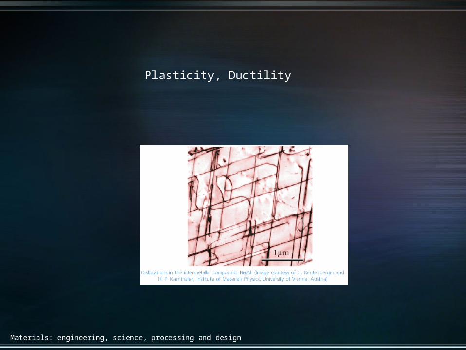
Plasticity, Ductility
Materials: engineering, science, processing and design
Yield strength is the stress beyond which a material becomes plastic – deformation is permanent
Determined by standard tensile testing proceduresUnits: Mpa - MN/m2 or psi - lb/in2
1 Mpa = 145.05 psi
Materials: engineering, science, processing and design
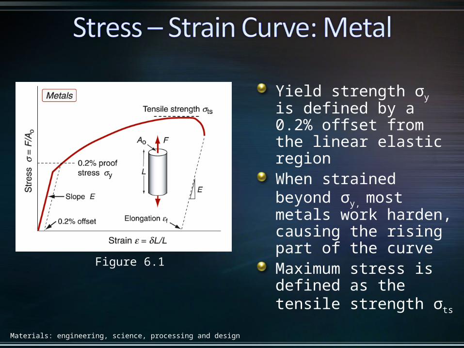
Figure 6.1
Yield strength σy is defined by a 0.2% offset from the linear elastic regionWhen strained beyond σy, most metals work harden, causing the rising part of the curveMaximum stress is defined as the tensile strength σts
Materials: engineering, science, processing and design
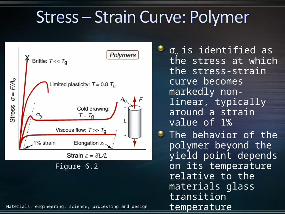
Figure 6.2
σy is identified as the stress at which the stress-strain curve becomes markedly non-linear, typically around a strain value of 1%The behavior of the polymer beyond the yield point depends on its temperature relative to the materials glass transition temperature
Materials: engineering, science, processing and design
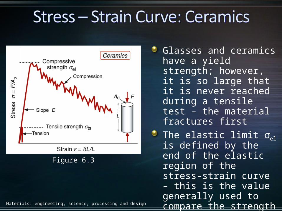
Figure 6.3
Glasses and ceramics have a yield strength; however, it is so large that it is never reached during a tensile test – the material fractures firstThe elastic limit σel is defined by the end of the elastic region of the stress-strain curve – this is the value generally used to compare the strength of ceramics with other materials
Materials: engineering, science, processing and design
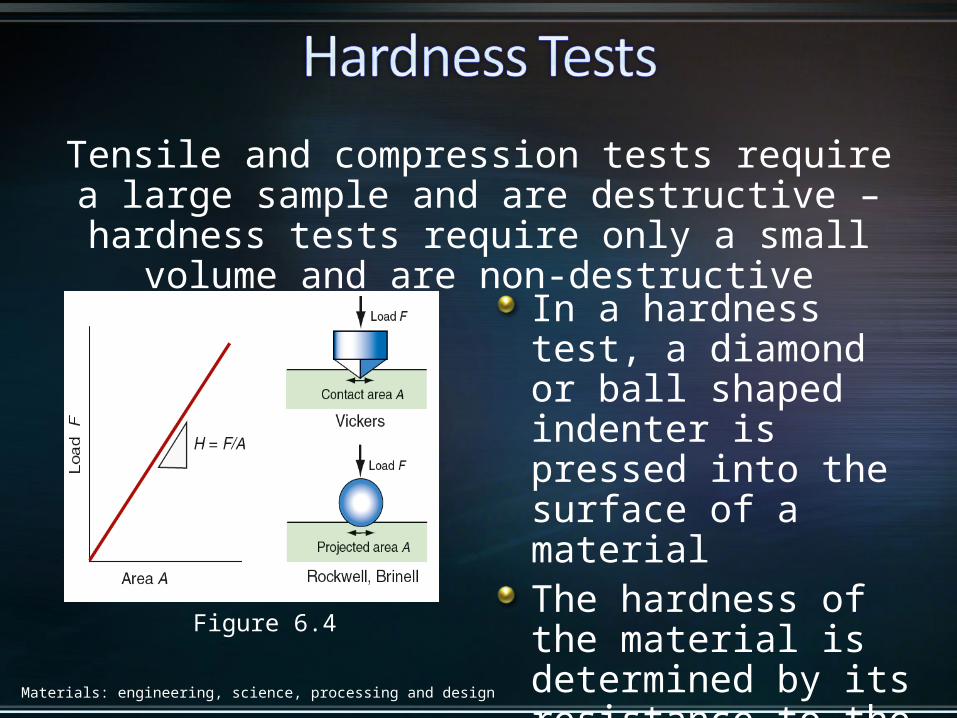
Figure 6.4
Tensile and compression tests require a large sample and are destructive – hardness tests require only a small
volume and are non-destructive
In a hardness test, a diamond or ball shaped indenter is pressed into the surface of a materialThe hardness of the material is determined by its resistance to the indentation
Materials: engineering, science, processing and design
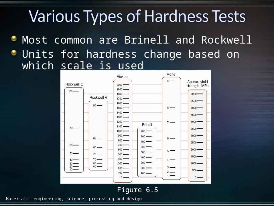
Figure 6.5
Most common are Brinell and RockwellUnits for hardness change based on which scale is used
Materials: engineering, science, processing and design
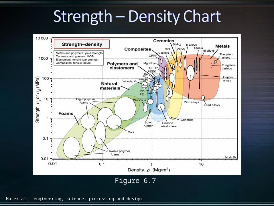
Figure 6.7
Materials: engineering, science, processing and design
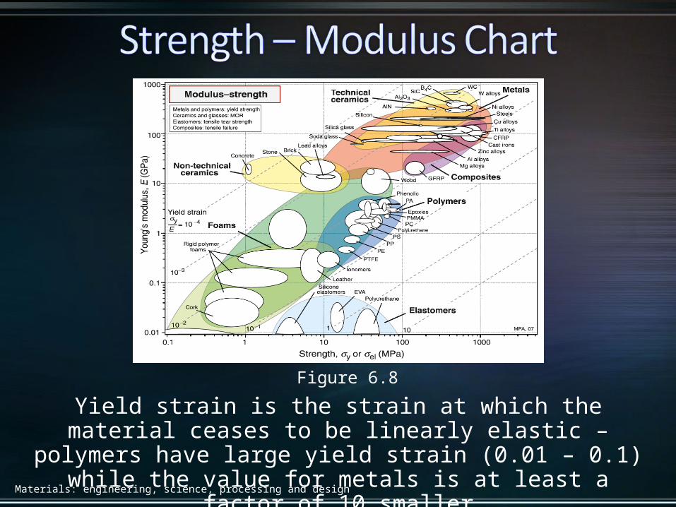
Figure 6.8
Yield strain is the strain at which the material ceases to be linearly elastic – polymers have large yield strain (0.01 – 0.1) while the
value for metals is at least a factor of 10 smaller

Materials: engineering, science, processing and design
Figure 6.9
Stress – strain curve for a single atomic bond Ideally, the strength of a
material is the force necessary to break inter-atomic bondsA bond is broken if it is stretched beyond about 10% of its original length – therefore the force needed to break a bond is roughly:

Materials: engineering, science, processing and design
Figure 6.10
Further calculations that account for the curvature of the force-distance curve predict a ratio of 1/15
Materials: engineering, science, processing and design
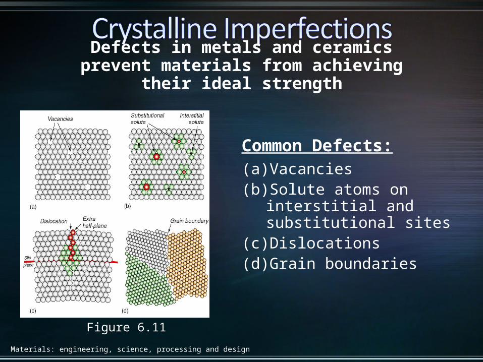
Figure 6.11
Defects in metals and ceramics prevent materials from achieving their ideal strength
Common Defects:(a) Vacancies(b) Solute atoms on interstitial
and substitutional sites(c) Dislocations(d) Grain boundaries
Materials: engineering, science, processing and design
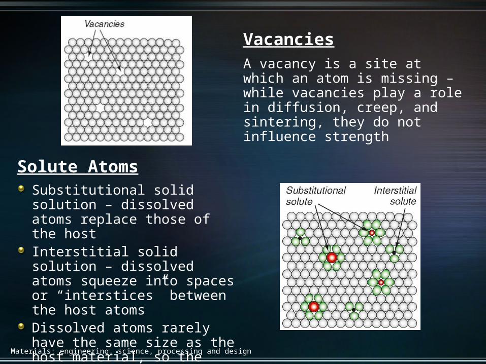
Solute AtomsSubstitutional solid solution – dissolved atoms replace those of the hostInterstitial solid solution – dissolved atoms squeeze into spaces or “interstices” between the host atomsDissolved atoms rarely have the same size as the host material, so the surrounding lattice is distorted
VacanciesA vacancy is a site at which an atom is missing – while vacancies play a role in diffusion, creep, and sintering, they do not influence strength

Materials: engineering, science, processing and design
DislocationsA dislocation is an extra half-plane of atoms in the crystal – in the figure, the upper part of the crystal has one more double-layer of atoms than the lower part – dislocations distort the lattice and make metals soft and ductile
Grain BoundariesGrain boundaries form when differently oriented crystals meet – the individual crystals are called grains, the meeting surfaces are grain boundaries

Materials: engineering, science, processing and design
Figure 6.12
The edge dislocation is made by cutting, slipping, and rejoining bonds across a slip planeThe dislocation line separates the part of the plane that has slipped from the part that has not(b) represents the resulting atomic configuration – called an edge dislocation because it is formed by the edge of the extra half-plan
Materials: engineering, science, processing and design
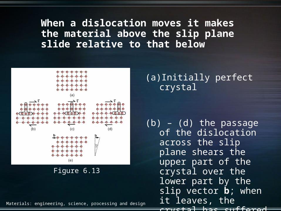
Figure 6.13
When a dislocation moves it makes the material above the slip plane slide relative to that below
(a) Initially perfect crystal
(b) – (d) the passage of the dislocation across the slip plane shears the upper part of the crystal over the lower part by the slip vector b; when it leaves, the crystal has suffered a shear strain
Materials: engineering, science, processing and design
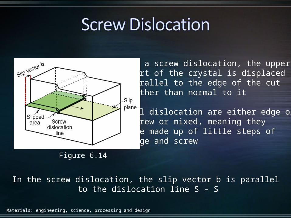
Figure 6.14
In a screw dislocation, the upperpart of the crystal is displacedparallel to the edge of the cutrather than normal to it
All dislocation are either edge or screw or mixed, meaning theyare made up of little steps of edge and screw
In the screw dislocation, the slip vector b is parallel to the dislocation line S – S
Materials: engineering, science, processing and design
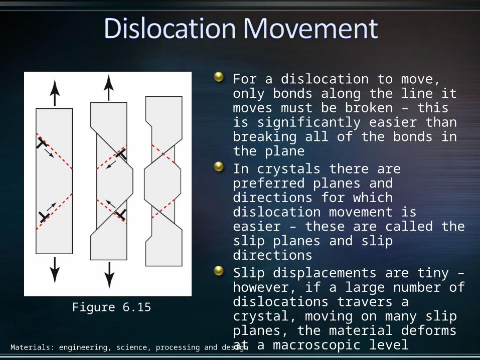
Figure 6.15
For a dislocation to move, only bonds along the line it moves must be broken – this is significantly easier than breaking all of the bonds in the planeIn crystals there are preferred planes and directions for which dislocation movement is easier – these are called the slip planes and slip directionsSlip displacements are tiny – however, if a large number of dislocations travers a crystal, moving on many slip planes, the material deforms at a macroscopic level

Materials: engineering, science, processing and design
Figure 6.16
Crystals resist the motion of dislocations with a friction-like resistance f per unit length
Dislocations move from an applied shear stress τ – as they movethe upper half of the crystal shifts relative to the lower half by
a distance b
Dislocations move if τ exceeds f/b
Materials: engineering, science, processing and design
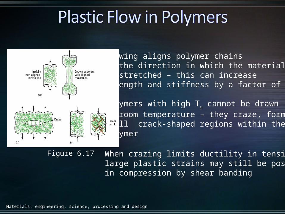
Figure 6.17
Drawing aligns polymer chainsin the direction in which the materialis stretched – this can increase strength and stiffness by a factor of 8
Polymers with high Tg cannot be drawnat room temperature – they craze, formingsmall crack-shaped regions within the polymer
When crazing limits ductility in tension,large plastic strains may still be possiblein compression by shear banding
Materials: engineering, science, processing and design
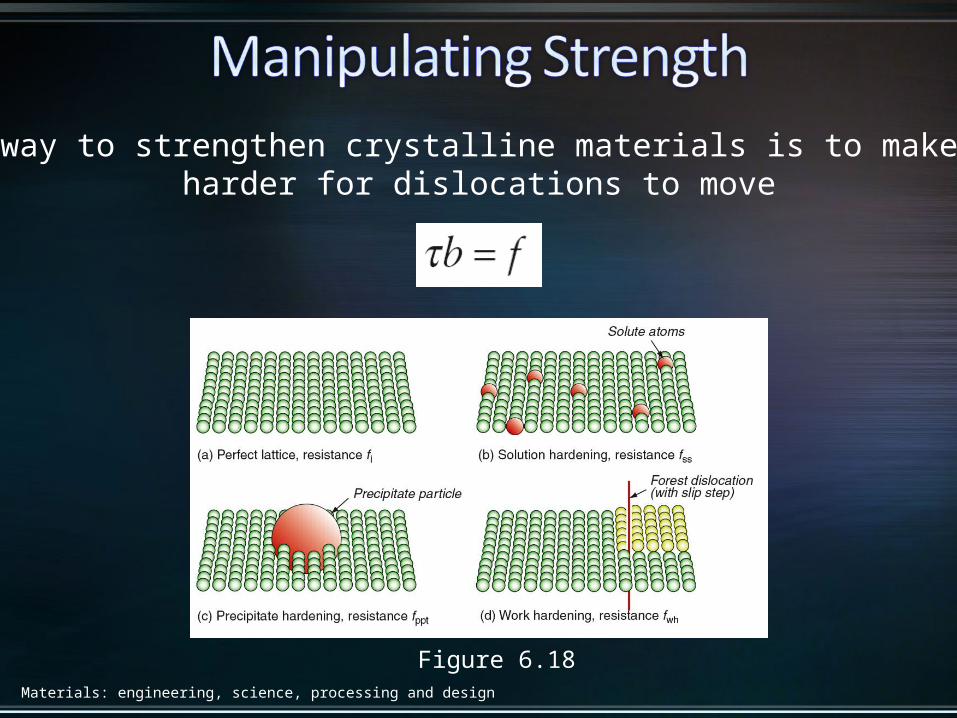
Figure 6.18
The way to strengthen crystalline materials is to make it harder for dislocations to move
Materials: engineering, science, processing and design
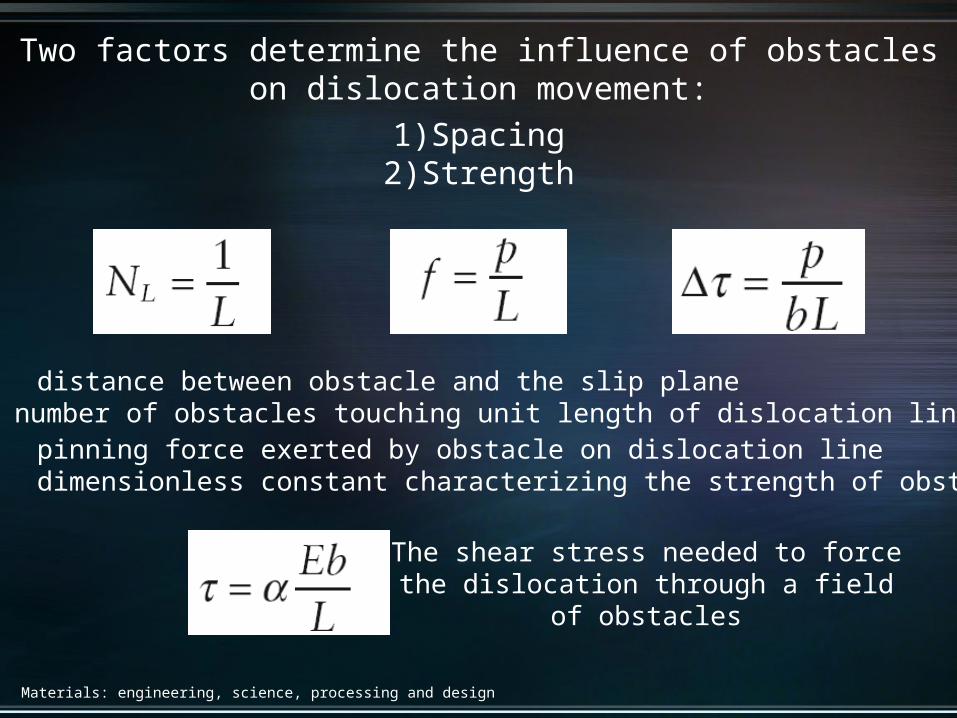
Two factors determine the influence of obstacleson dislocation movement:
1)Spacing2)Strength
L: distance between obstacle and the slip planeNL: number of obstacles touching unit length of dislocation linep: pinning force exerted by obstacle on dislocation lineα: dimensionless constant characterizing the strength of obstacle
The shear stress needed to forcethe dislocation through a field
of obstacles
Materials: engineering, science, processing and design
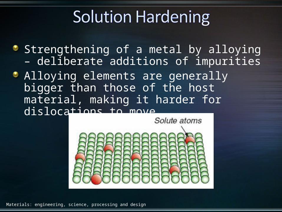
Strengthening of a metal by alloying – deliberate additions of impuritiesAlloying elements are generally bigger than those of the host material, making it harder for dislocations to move
Materials: engineering, science, processing and design
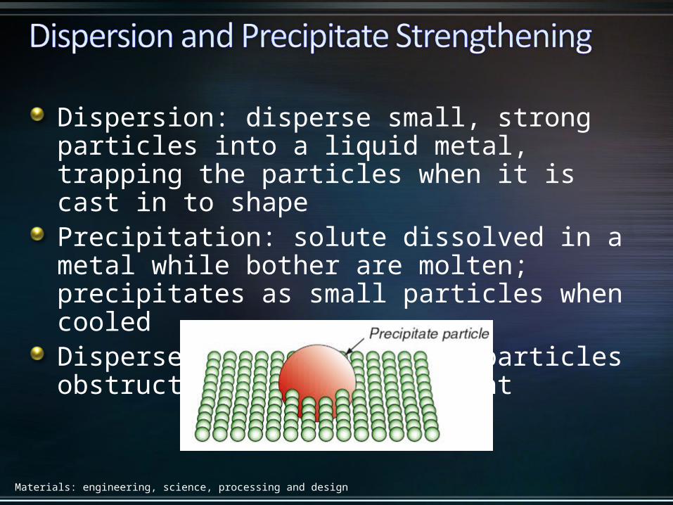
Dispersion: disperse small, strong particles into a liquid metal, trapping the particles when it is cast in to shapePrecipitation: solute dissolved in a metal while bother are molten; precipitates as small particles when cooledDispersed and precipitated particles obstruct dislocation movement

Materials: engineering, science, processing and design
Caused by the accumulation of dislocations generated by plastic deformationDislocation density is defined as the length of dislocation line per unit volume
Materials: engineering, science, processing and design
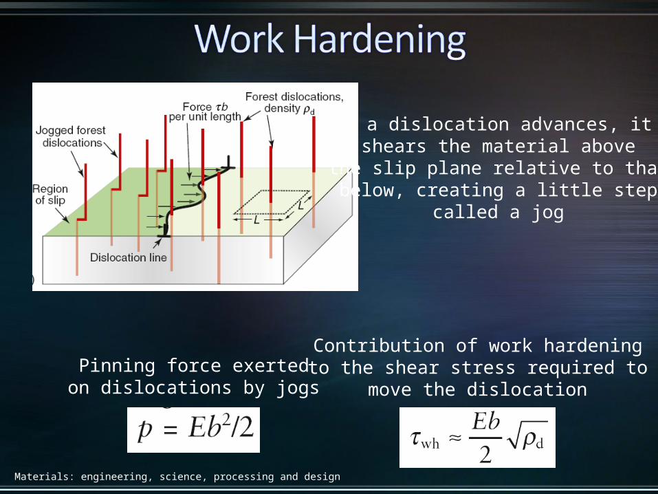
Pinning force exertedon dislocations by jogs
Contribution of work hardeningto the shear stress required to
move the dislocation
If a dislocation advances, it shears the material above
the slip plane relative to thatbelow, creating a little step
called a jog
Materials: engineering, science, processing and design
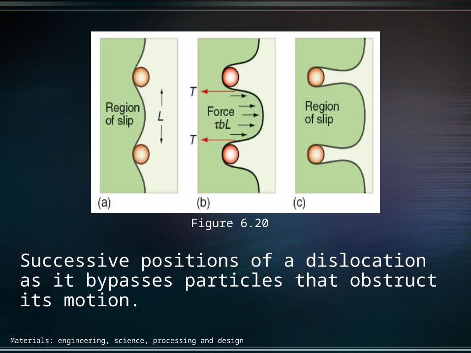
Figure 6.20
Successive positions of a dislocation as it bypasses particles that obstruct its motion.
Materials: engineering, science, processing and design
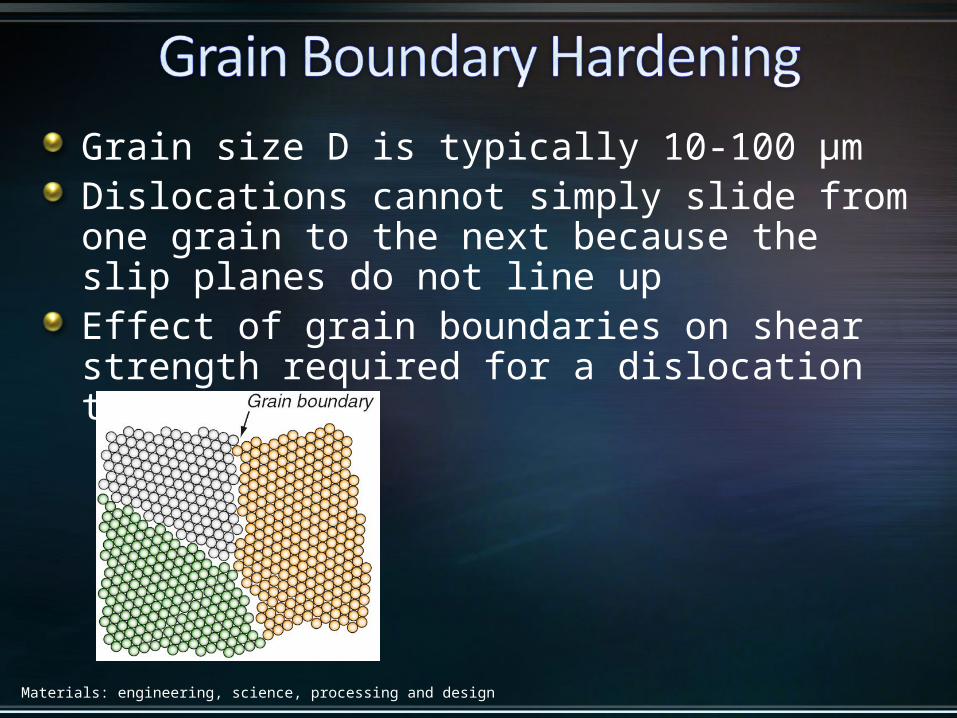
Grain size D is typically 10-100 μmDislocations cannot simply slide from one grain to the next because the slip planes do not line upEffect of grain boundaries on shear strength required for a dislocation to move
Materials: engineering, science, processing and design
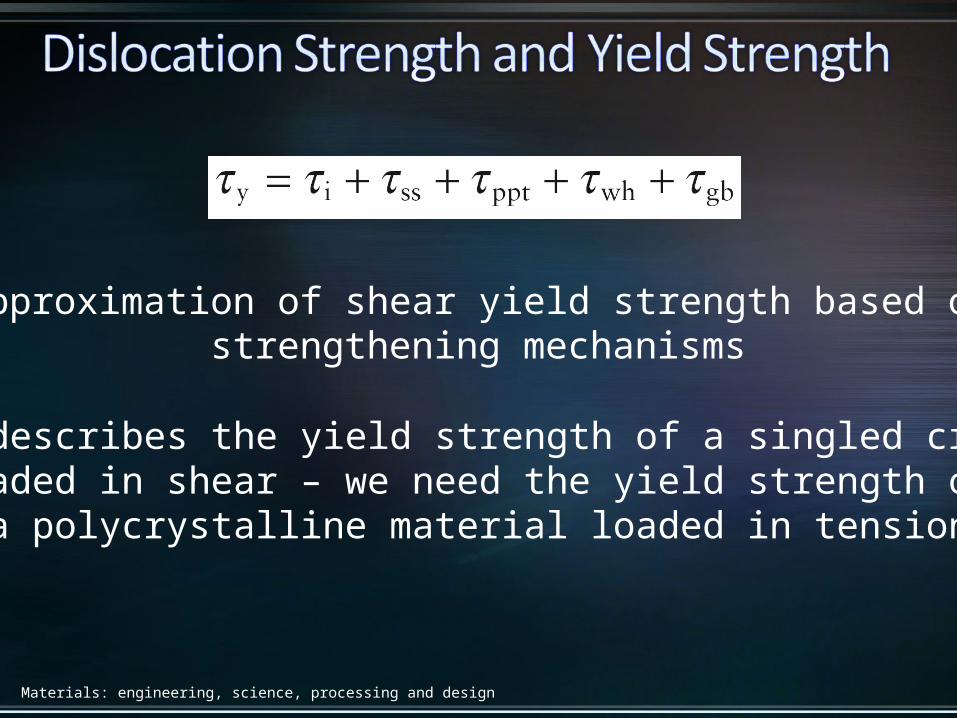
Approximation of shear yield strength based onstrengthening mechanisms
This describes the yield strength of a singled crystalloaded in shear – we need the yield strength of
a polycrystalline material loaded in tension
Materials: engineering, science, processing and design
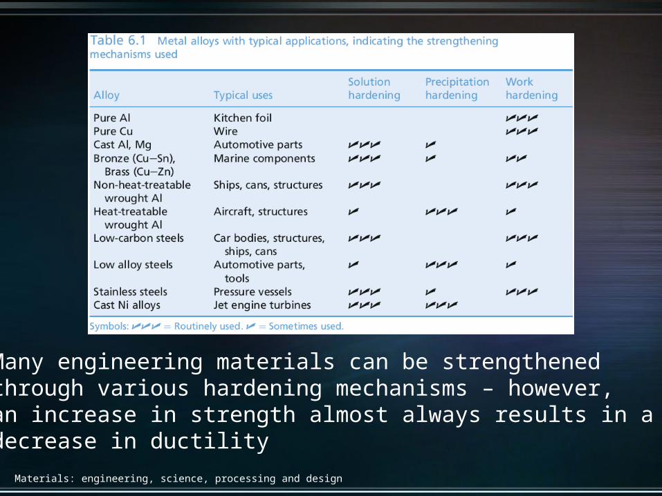
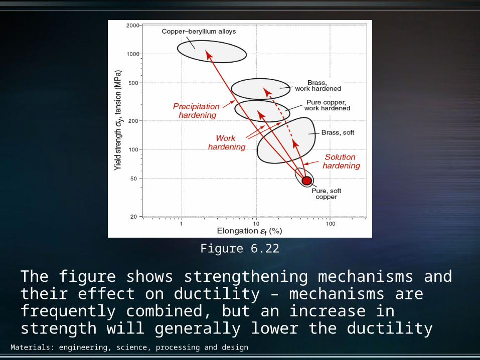
Many engineering materials can be strengthened through various hardening mechanisms – however,an increase in strength almost always results in a decrease in ductility
Materials: engineering, science, processing and design
Figure 6.22
The figure shows strengthening mechanisms and their effect on ductility – mechanisms are frequently combined, but an increase in strength will generally lower the ductility
Materials: engineering, science, processing and design
Dislocations do not play a role in the strength of non-crystalline solids – instead, the relative slippage of two segments of a polymer chain must be consideredImpeding the slippage of molecular chains can be done through blending, drawing, cross-linking, and by reinforcement with particles, fiber, and fabrics
Materials: engineering, science, processing and design
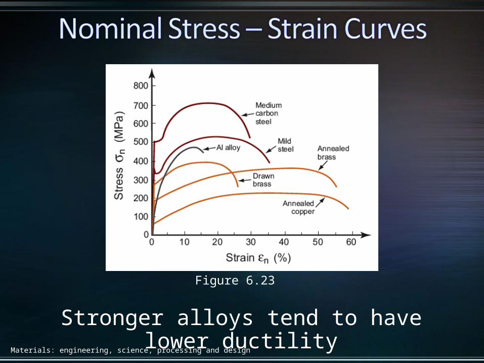
Figure 6.23
Stronger alloys tend to have lower ductility
Materials: engineering, science, processing and design
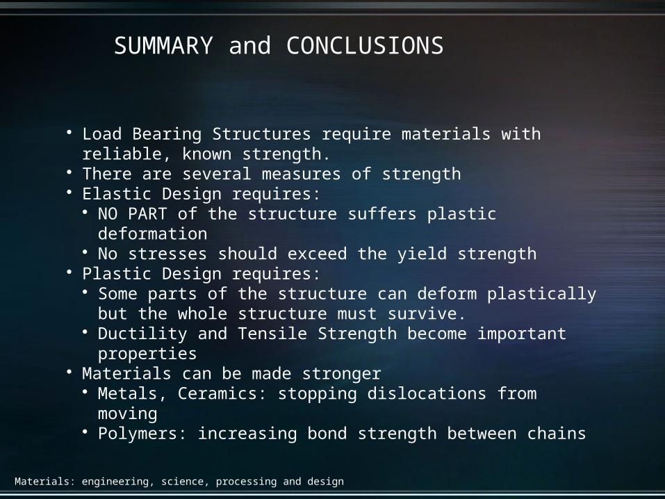
Load Bearing Structures require materials with reliable, known strength. There are several measures of strength Elastic Design requires:
NO PART of the structure suffers plastic deformation No stresses should exceed the yield strength
Plastic Design requires: Some parts of the structure can deform plastically but the whole structure
must survive. Ductility and Tensile Strength become important properties
Materials can be made stronger Metals, Ceramics: stopping dislocations from moving Polymers: increasing bond strength between chains
SUMMARY and CONCLUSIONS