materials in extreme environments for energy, accelerators ... · sis100 heavy ion synchrotron at...
TRANSCRIPT

Materials in extreme environments for energy, accelerators and spaceapplications at ELI-NP.
Asavei, T., Tomut, M., Bobeica, M., Aogaki, S., Cernaianu, M. O., Ganciu, M., ... Zamfir, N. V. (2016). Materialsin extreme environments for energy, accelerators and space applications at ELI-NP. Romanian Reports inPhysics, 68(Supplement), S275-S347.
Published in:Romanian Reports in Physics
Document Version:Peer reviewed version
Queen's University Belfast - Research Portal:Link to publication record in Queen's University Belfast Research Portal
Publisher rights© 2016 Editura Academiei Romane
General rightsCopyright for the publications made accessible via the Queen's University Belfast Research Portal is retained by the author(s) and / or othercopyright owners and it is a condition of accessing these publications that users recognise and abide by the legal requirements associatedwith these rights.
Take down policyThe Research Portal is Queen's institutional repository that provides access to Queen's research output. Every effort has been made toensure that content in the Research Portal does not infringe any person's rights, or applicable UK laws. If you discover content in theResearch Portal that you believe breaches copyright or violates any law, please contact [email protected].
Download date:31. Jan. 2020
HPLS–TDR4 MATERIALS IN EXTREME ENVIRONMENTS FOR
ENERGY, ACCELERATORS AND SPACE APPLICATIONS AT
ELI-NP
T. ASAVEI1,*, M. TOMUT2, M. BOBEICA1, S. AOGAKI1, M.O. CERNAIANU1, M. GANCIU3,
S. KAR4, G. MANDA5, N. MOCANU6, L. NEAGU1, C. POSTOLACHE6, D. SAVU6,
D. STUTMAN1, D. VIZMAN7, D. URSESCU1, S. GALES1, N. V. ZAMFIR1
1Extreme Light Infrastructure-Nuclear Physics, Horia Hulubei National Institute for Nuclear Physics
and Engineering, P.O.Box MG-6, 077125, Magurele, Romania,
2GSI Helmholzzentrum für Schwerionenforschung GmbH, 64291 Darmstadt, Germany,
3National Institute for Laser, Plasma and Radiation Physics, 409 Atomistilor Street, P.O. Box MG-36,
077125, Magurele, Romania,
4School of Mathematics and Physics, The Queen’s University of Belfast, BT7 1NN Belfast, UK,
5Cellular and Molecular Medicine Department, “Victor Babes” National Institute of Pathology,
99-101 Splaiul Independentei, Bucharest 050096, Romania,
6Horia Hulubei National Institute for Nuclear Physics and Engineering, P.O.Box MG-6, 077125,
Magurele, Romania,
7Faculty of Physics, West University of Timisoara, Bd. V. Parvan 4, 300223 Timisoara, Romania,
*Corresponding author: [email protected]
Abstract. As a leading facility in laser-driven nuclear physics, ELI-NP will develop
innovative research in the fields of materials behavior in extreme environments and radiobiology,
with applications in the development of accelerator components, new materials for next generation
fusion and fission reactors, shielding solutions for equipment and human crew in long term space
missions and new biomedical technologies. The specific properties of the laser-driven radiation
produced with two lasers of 1 PW at a pulse repetition rate of 1 Hz each are an ultra-short time scale,
a relatively broadband spectrum and the possibility to provide simultaneously several types of
radiation. Complex, cosmic-like radiation will be produced in a ground-based laboratory allowing
comprehensive investigations of their effects on materials and biological systems. The expected
maximum energy and intensity of the radiation beams are 19 MeV with 109 photon/pulse for photon
radiation, 2 GeV with 108 electron/pulse for electron beams, 60 MeV with 1012 proton/pulse for
proton and ion beams and 60 MeV with 107 neutron/pulse for a neutron source. Research efforts will
be directed also towards measurements for radioprotection of the prompt and activated dose, as a
function of laser and target characteristics and to the development and testing of various dosimetric
methods and equipment.
Key words: ELI-NP, material science, space science

T. Asavei et al.
2
1. INTRODUCTION
Dosimetry, ionizing radiation metrology and radiation induced biological damage
are major active research areas in nuclear (bio)physics and engineering. Their
applications extend from the nuclear power plants to medicine and from space
science to material science and to accelerators engineering. Typical research that
will be described in this paper relates to testing of materials for accelerator sub-
systems, testing of materials for space science (electronics components), material
science research (surface and volume modification, nanotechnology), biomedical
research (radiation effects on cells, tissues, organisms), testing and development of
detectors as well as testing of irradiated optical components.
2. PHYSICS CASES
2.1 TESTING OF NEW MATERIALS FOR ACCELERATOR
COMPONENTS
In the framework of this technical design report (TDR) the study of
materials behaviour in extreme environments will be a central topic, with a direct
application to the development of accelerator components and societal applications
like the understanding of structural materials degradation in next generation fusion
and fission reactors or the shielding of equipment and human missions in outer
space. Testing of novel materials for accelerator components at the future high–
power facilities like the Facility for Antiproton and Ion Research (FAIR), the High
Luminosity Large Hadron Collider (HL-LHC), the Facility for Rare Isotope Beams
(FRIB), neutrino factories and the European Spallation Source (ESS) in conditions
of radiation, temperature and pressure similar to the operation scenarios would be
possible by using “cocktails” of laser driven particles and laser induced shock
waves. The Extreme Light Infrastructure-Nuclear Physics (ELI-NP) through the
experimental area E5 offers a unique testing facility complementary to accelerator
irradiation. The availability of two high-intensity short-pulse lasers would enable
pump-probe experiments using laser based diagnostic enabling structural
degradation studies during irradiation on a much finer time scale.
HPLS–TDR4 Materials in extreme environments at ELI-NP
3
2.1.1. Testing of accelerator materials at fast energy deposition and mixed radiation
fields
With the development of new high-power accelerator facilities, materials
that have been traditionally used for targets, beam protection elements, beam tube
and windows are facing new challenges, being solicited to their limits by extreme
thermo-mechanical loads and radiation fields during operation. Particularly in the
case of accelerators using bunched beams like FAIR, the Large Hadron Collider
(LHC) and neutrino production facilities, targets and selected accelerator
components will experience shock waves induced by energy deposited within the
beam spot. Experiments under similar operation conditions are required to develop
and apply high speed monitoring techniques, and to supply more detailed
information for better understanding the failure mechanism by crack formation,
propagation, and fracture processes. Experimental results will allow lifetime
estimates for these elements and additionally provide input data for simulations.
A. Super-FRS target at FAIR
At the future FAIR facility, to be built at GSI Darmstadt, it will be possible
to perform experiments in different fields of physics in a parameter range that is
presently inaccessible. A wide range of particles with energies up to 1.5 A GeV
will be used for the production of fragments by projectile fragmentation/fission at
the proposed superconducting fragment separator (Super-FRS) [1]. The Super-FRS
will be the most powerful in-flight separator for exotic nuclei at relativistic
energies. Rare isotopes of all elements up to uranium will be produced and
spatially separated within some hundred nanoseconds, enabling the study of very
short-lived nuclei.
As the resolving power of the Super-FRS is inversely proportional to the
beam spot radius, it is required to minimize the transversal beam dimensions at the
position of the production target. The final goal would be a primary driver beam
radius in x and y direction of the order of 1-2 mm. The combination of high
intensities of a driver beam, large projectile Z-values, and small radii of the driver-
beam spot will lead to high induced power densities inside the targets. Similar to
the present fragment separator facility, both slow and fast extraction from the
SIS100 heavy ion synchrotron at FAIR will be used: the former with typical
extraction times of a few seconds for counter experiments at the experimental
caves, the latter for experiments with radioactive secondary beams in the storage
rings where driver beams with a typical pulse length of 50 ns are required.
The high instantaneous power-deposition in the target by fast-extracted
beams (up to 200 GW) may lead to explosive regimes [2]. As a result, the target

T. Asavei et al.
4
could be destroyed by a single beam pulse. Therefore, new technical developments
for the production targets are required in order to profit from the full potential of
the Super-FRS for exotic nuclei production. Furthermore, the high intensities of a
driver beam will change the technical requirements for the beam dump. A proper
technical solution to the problems connected with the specific energy deposition of
heavy ions in the fast and the slow extraction modes has to be found.
In slow extraction mode, the expected maximum deposited beam power of
12 kW induced by 238
U driver beam is comparable to the values found in operating
facilities (e.g., at the Paul Scherrer Institute (PSI) [3]). Following the longstanding
experience at PSI, a concept of rotating graphite wheel as a Super-FRS target has
been chosen [4]. On the other hand, in fast extraction mode, two options were
initially considered namely, the same rotating-wheel concept which is also chosen
for fast extraction with a low deposited specific beam power (low projectile Z
and/or low intensities, extended size of the beam spot) and, for the highest power
densities a windowless liquid-metal has been initially considered, but simulation
have shown that the jet will be destroyed by the pulsed beam.
The concept of a rotating-wheel target should be applied for fast-extracted
beams, as long as the critical parameters of graphite (e.g., temperature, pressure)
are not exceeded. For this purpose, a detailed knowledge on the response of
graphite material induced by pulsed high-intensity ion beams is essential. The steep
temperature gradients generated in solid materials during a passage of beam
particles excite stress waves. These stress waves propagate then in different
directions towards the surface of the solid target, where they are rejected and excite
natural oscillations of the target. After a few reflections the stress waves vanish due
to damping.
Experiments on graphite target response under pulsed ion beams have been
done up to now at the high energy, high temperature (HHT) beamline at the GSI
Helmholtz Center for Heavy Ion Research with fast extracted relativistic ion beams
and at the Universal Linear Accelerator (UNILAC) based also at GSI with GeV U
ions pulses 100 μs long. In both type of experiments, the beam intensity was not
high enough to lead to thermo-mechanical failure of the pristine target. Failure in
the last situation was due to decreased fatigue resistance of target material that has
been accumulating radiation damage (Fig. 1). The energy deposition/pulse can be
increased by using very intense proton and ion beams produced by laser
acceleration or directly by exposing the material to laser beam.

HPLS–TDR4 Materials in extreme environments at ELI-NP
5
Fig. 1 – Failure of graphite target foils exposed to 5×10¹⁴ 238U ions/cm2, 150 μs pulse length, 0.4 Hz,
4.8 MeV/u.
B. Secondary collimators for HL-LHC
Particle beam propagation is associated with unavoidable losses. The
losses include: primary halo of protons – managed by primary collimator,
secondary halo – managed by secondary collimator and tertiary halo managed by
absorber.
At each stage there are electron and hadron showers accompanying proton
halos. Behind the collimators there are SC magnets and particle physics
experiments. In some solutions, like in SIS 100 at FAIR, the primary collimator is
a thin foil which acts like a scatterer of the halo particles and the secondary
collimators in a form of bulky blocks are necessary to absorb the scattered
particles. Crystals (acting as primary aperture) assisted collimation assumes usage
of elastic and diffractive scattering. The crystal is bent and behaves like a Bragg
grating for scattered particles.
The collimation system must satisfy two main functions: Multi-stage Beam
Cleaning (BC), i.e. removing stray particles which would induce quenches in SC
magnets; and Machine Protection, i.e. shielding the other machine components

T. Asavei et al.
6
from the catastrophic consequences of beam orbit errors. Classical C-C carbon
composite collimators are affected by intrinsic limitations which may ultimately
limit LHC performances: low Z-material of the collimator limits cleaning
efficiency, poor electrical conductivity material of collimator means high RF
impedance, limited radiation hardness of collimator material means reduced
lifetime.
Innovative materials are needed for accelerator collimator jaws for the
upgrade of the LHC. The research on collimator and materials for higher beam
power (ColMat) consists of research and development of novel materials, advanced
numerical simulations, material testing, prototype design and manufacturing.
ColMat research and development within the European Coordination for
Accelerator Research and Development (EuCARD) project focuses on Metal
Matrix Composites (MMC) with diamond and graphite reinforcement as they have
the potential to combine the properties of diamond and graphite (high thermal
conductivity, low density, low CTE) with those of metals (strength, high Poisson
ratio, high Young’s modulus). Sintering techniques include rapid hot pressing
(RHP) and liquid infiltration. Spark plasma sintering (SPS) is a technology of the
future. Materials under investigation are Copper-diamond (Cu-CD) and
Molybdenum- Graphite (Mo-Gr). The materials are tested for: shock wave
analysis, smooth particle hydrodynamics (material fragmentation), irradiation
studies with proton and carbon ion beams – swelling measurements and
mechanical tests.
Cu-CD composites are produced by RHP from 60% diamond and 40% Cu.
No diamond degradation in reducing atmosphere is observed. Diamond
graphitization starts at approximately 1300 C. Thermal conductivity is around
500 W/mK, and electrical conductivity 12.6 MS/m. There is no direct interface
between Cu and CD because of a lack of affinity. Mechanical strength is average
120 MPa. Cu low melting point limits applications for highly energetic accidents.
Mo-Gr composites are under intense research and development. Graphite
addition has low CTE, low density, high thermal conductivity, high melting point
and high shock wave damping. The properties are similar to Mo-CD but the
mechanical strength is not yet satisfactory. One of the solutions is to use Mo-
Gr/Mo sandwich which consists of Mo-Gr core with Mo layers.
The aims of collimator material experiments at ELI-NP are: to test
traditional and novel materials under extreme conditions they may encounter in
case of accidental beam impacts; to quantify material damage for LHC operating
scenarios; to fully characterize novel materials currently under development for
new generation of collimators; to benchmark advanced numerical solutions, in-
depth but based on limited and scarce published data on material constitutive
models; to collect, mostly in real time, experimental data on constitutive models of
HPLS–TDR4 Materials in extreme environments at ELI-NP
7
materials, including equation of state, strength models, failure models.
There are several main objectives for material research and development
for accelerator technology. These objectives have been turned into a set of figures
of merit (FoM) to assess relevant materials. For instance, in order to reduce the RF
impedance of the material one needs to maximize its electrical conductivity, to
maintain/improve geometrical stability in nominal conditions one needs to
maximize the stability indicator Steady-state Stability Normalized Index (SSNI), to
maintain the robustness in accidental scenarios one needs to maximize the
robustness indicator Transient Thermal Shock Normalized Index (TSNI), to
improve cleaning efficiency by relevant absorption rate one needs to increase
radiation and nuclear interaction length by high enough atomic number, to improve
the maximum operational temperature one needs to increase the melting
temperature. Additional standard requirements include radiation hardness, ultra-
high vacuum (UHV) compatibility and so forth.
C. Experiments
We propose to perform the experiment with exposure of thin targets, as
primary or secondary target, to increasing intensities of laser, or laser-generated
proton, electron and ion beams.
For in-situ monitoring and alignment of our graphite foil targets, cameras
will be used. The vibration amplitudes and velocities of the sample surface and
spalled fragments will be measured by means of a VISAR and streak cameras
placed outside the target chamber. Mirrors will be used for alignment on the
targets. The survival to increasing energy density, of materials foreseen as
candidates for accelerator components will be investigated by varying the intensity
of laser accelerated particle beams. This will be achieved either by changing the
intensity of the laser pulse or by changing the distance between the target for laser
acceleration and our secondary target.
Off-line tests of exposed samples will include structural investigations using
profilometry XRD, electron microscopy, Raman spectroscopy and mechanical tests
using nanoindentation. These experimental techniques will help in understanding
what is the failure mechanism of targets for high intensity pulsed beams and
determine failure criteria for these targets. Post-irradiation microstructural
investigations and positron annihilation will provide insight into the physics of
defect evolution and recombination at short time scale in target materials.
Advanced multi-scale materials simulations can be used in conjunction with these
experiments to develop models of the physical phenomena governing the response
of materials under extreme environments.

T. Asavei et al.
8
2.1.2. Laser induced shock waves
By focusing a short-pulsed laser (ns to fs pulses) on the surface of a solid target,
reaction shock waves can be induced provided that the power density of the
focused beam is high enough (larger than 109 W/cm
2). The laser induced shock
waves are of great importance for studies of matter in extreme conditions, as they
permit investigations of high-temperature high-pressure regimes in solids. The
pressure obtained in the case of shock wave compression is of the order of
magnitude of hundreds of GPa.
A laser pulse creates a spherical shock wave in the target material.
Overlapping of multiple shock waves is also possible by generating spatially
separated pulses and thus shock waves interference can be achieved [5].
2.1.3. On-line laser based diagnostic
Testing novel composite materials and proposed beam protection elements
and target designs will aim at increasing the performance at nominal beam
intensities. Online imaging techniques based on PW laser-generated X-rays,
protons, and neutrons are new means for acquiring time-resolved information of
transient phenomena involved in ion-beam induced shock propagation. For lifetime
estimation of the Super-FRS target and beam catchers at FAIR and collimators at
LHC, shock and stress waves experiments will be performed on samples that
already accumulated radiation damage in-situ and which cannot be transported
outside irradiation facilities for experiments due to radiation safety concerns.
Detecting the generation of such extreme conditions in dense samples and actually
measuring its properties will require advanced diagnostic capabilities based on
highly penetrating probe radiation. In addition, extreme brightness is necessary to
provide sufficient flux within the short life-time of the samples at extreme
conditions. High-energy high-intensity laser systems allow generation of a variety
of highly penetrating secondary radiation at ultra-high intensities.
2.1.4. Pump-probe experiments on radiation-induced defect cluster
evolution and ion track formation processes in solids
Time-resolved in-situ analysis will permit us to explore ultra-short
processes associated with the formation of ion tracks in solids using ultrafast laser-

HPLS–TDR4 Materials in extreme environments at ELI-NP
9
based diagnostic. At present, the coupling of the densely excited electron
subsystem to the motion of the atoms in the lattice is neither understood nor
experimentally accessible. Electronic excitation processes and subsequent lattice
heating and relaxation occur on a time scale spanning from hundreds of
femtoseconds to tens of picoseconds. Access to experimental data in this short time
window will allow benchmarking of existing track models at ambient or high-
pressure. Besides the track formation process, it is also important to monitor in-situ
the dynamics of irradiation induced defects on larger time scales. Clustering,
defect-sinks annihilation and temperature-induced annealing are all important
processes that determine dimensional changes, thermo-mechanical and electrical
properties of irradiated materials with large impact on their nuclear application. A
very dynamic field of using laser-generated particles and radiation such as X-rays,
positrons, protons and neutrons as probes for investigating these processes in
pump-probe experiments is now spreading in different scientific communities from
hard condensed matter to high-energy density matter.
2.1.5. Laser modification of materials for accelerator applications
Femtosecond lasers can be used for materials micromachining and local
generation of non-equilibrium phases. 3D architectures can be generated using both
beams. One example would be “writing” of complex graphitized electrode
structures in diamond detectors for increased radiation hardness.
2.2 TESTING AND DEVELOPMENT OF DETECTORS
Building of the new ELI-NP facility should comply with Romanian Radiation
Safety Norms developed by Romanian Regulatory Body – National Commission
for Nuclear Activity Control (CNCAN). In this way the licensing of ELI-NP will
be performed in steps. First step is Construction License. Construction License
allows to mount the accelerator and high intensity laser source. Also the
construction license allows checking the radiation protection shielding. Radiation
protection shielding refers to walls, doors, ceilings and so forth. Radiation
protection measurements should be given priority during all mounting steps: for
accelerator mounting, for high intensity PW laser and at the end for both
accelerator and laser. There are needs to measure the primary electron beam and
gamma beams. Due to high energy gamma beams (19.5 MeV) we expect to have
photo-neutron contamination too. From these reasons the radiation protection of
workers is very important and should comply with Radiation Safety Norms.

T. Asavei et al.
10
Radiation protection measurement performed in order to check the
radiation protection shielding will address the worst operating conditions: highest
energy and highest intensity of the electron and gamma beams. Measurements will
be performed for: primary beam (electron or gamma beam), measurement in
controlled area (irradiation room and control room), and in the survey area (area
close to control area). Radiation protection measurements in primary beam will be
performed using ionization chambers like STARDOOR. These chambers are
calibrated to primary standard at PTB which provide higher measurement
precision. The ISO 17025:2005 accreditation provides high quality in delivered
measurement results according to applicable standards.
The field characteristics can be tested using a film densitometry method. A
special film is exposed to electron or gamma beam, and then is read using a high
precision analogical densitometer. 3D reconstruction in film densitometry provides
information regarding radiation field characteristics, e.g. beam distribution, field
homogeneity, penumbra etc., as well as amount of exposure.
The measurement in controlled area involves measurements of all leakage
photons, direct beam photons, scattered photons, electrons and neutrons. Because
there is a combined exposure field, the radiation protection measurements will be
performed to obtain isodose area distribution. These measurements will provide
information on hot point of exposure. The measurement will be performed with
high precision spherical ionization chamber. The photoneutrons will be measured
with Kuhn ionization chamber. All measurements will be doubled with film
dosimetry method.
The investigations in control room and all survey area will provide
information on exposure level of professional exposure occupational personnel and
for public exposure. The measurement for radiation protection of workers and
public should be performed with ionization chamber. The STARDOOR laboratory
will perform measurements with spherical chamber. All measurements will be
doubled with film dosimetry method. The exposure to ionizing radiation in control
room and in survey area should comply with CNCAN requirements.
New research will be performed by STARDOOR laboratory in development of
new radiation detection systems for example continuing the work on new radiation
detection development based on optical fiber. The previous laboratory’s work
shows a possibility to use optical fiber as real time dosimeter.
We would like to investigate also the possibility to use SSNTD type CR39 as
neutron detectors. Shape of neutron track in CR39 detector could provide
information on neutron energy. STARDOOR laboratory also will study the thin
film reaction to electron and photon beam.

HPLS–TDR4 Materials in extreme environments at ELI-NP
11
2.3 EVALUATION OF HIGH ENERGY IONIZING RADIATION EFFECTS
IN MATERIALS
2.3.1. High energy ionizing radiation in space environment
Space vehicles, satellites, equipment and astronauts must perform current activities
in a hostile environment under stress agents such as: natural space radiation,
exposure at cryogenic or high temperature conditions, high vacuum environment
and high velocity cosmic dust and micrometeorites.
A. Space radiation environments
Cosmic rays (CR), discovered in 1912 by Victor Hess, are high energy particles
generated by astrophysical phenomena [6]. The CR can be classified in two main
classes: (a) transient radiation and (b) trapped radiation.
A.1 The transient radiation
The transient CR consists of Galactic Cosmic Ray (GCR) and Solar Cosmic
Radiation (SCR). GCR generated in Milky Way space and outside of the galaxy,
contain mainly hadrons components (about 85% protons, 12% helium nuclei, and
less than 1% heavy ions with composition [7], almost 2% leptons [8] and
electromagnetic particles (gamma and X-rays). Maximum energy of the particles is
more than 1.610-17
J (1 TeV).
SCR is composed of two categories of radiation, low energy solar-wind
particles that are constantly emitted from the sun, and highly energetic Solar
Particle Events (SPEs). Solar wind is a neutral, continuous stream of charged
particles emanating from Sun’s corona. Solar wind consists of protons (95%
relative abundance), helium nuclei (approximately 4% relative abundance), other
heavy ions (less than 1% relative abundance) and electrons. The solar wind
particles energies are lower than a few keVs.
SPEs are high energy and high density particles generated by two solar
storm phenomena, (a) solar flares, and (b) coronal mass ejections (CMEs). Solar
flares are large explosive events associated with intense releases of energy
(electromagnetic rays) and accelerated particles, (especially protons and electrons).
Energy of the charges particles and gamma rays can reach values of the 1.610-10
J
(1 GeV). CMEs are material ejections from Sun’s photosphere into the
interplanetary space. A large CME can eject approximately 1017
grams of plasma

T. Asavei et al.
12
into solar system space in several hours. The frequency of CME is correlated with
the Sun and sunspots cycles [9].
The typical 11 year cycle of the sun is characterized by a period of four
years of relative inactivity, followed by seven years with increased numbers of
SPE's. These ejections of high energy particles are highly directed, affecting only
small regions of space, but are characterized by very high particle fluxes and can
be extremely hazardous to space systems and crewed space vehicles and astronauts.
During the period of minimum solar activity, about one CME per week has been
determined; during maximum solar activity, two to three CME per day were
observed [9]. The energy is usually up to order of 1.610-9
J (100 MeV), but
exceptionally can reach approximately 1.610-11
J (10 GeV). The flux is strongly
related to the solar cycle, varying therefore also by several orders of magnitude
[10, 11].
A.2. Trapped radiations
The trapped radiations represent energetic charged particles long time retained by
the magnetic traps of the planetary magnetic fields. For the Earth, the interaction
between solar wind and GCR with terrestrial magnetic field results in two distinct
torus-shaped layers around the Earth, named Van Allen belts. In the inner belt
consists of trapped protons with energies between 6.410-12
J (40 keV) and
0.810-10
J (500 MeV) [12]. The outer belt consist mainly of trapped electrons with
energies in 6.410-12
J (40 keV) and 1.1210-9
J (7 MeV) range. In addition, the Van
Allen belts contain also small amounts of 4He nuclei and low energy heavier ions
[13].
Similar radiation belts have been discovered around other planets with
sufficiently large dipole magnetic moment. High radiation fields were identified
near Jupiter, Saturn, and Uranus [14] associated with trapped radiation belts similar
to Earth’s belts. Jupiter’s magnetosphere is very extensive. Its linear dimensions
exceed the size of Earth’s magnetosphere by 2 orders of magnitude. The front bow-
shock is located at a distance of around 8 million km from Jupiter.

HPLS–TDR4 Materials in extreme environments at ELI-NP
13
A.3. Space radiation effect
Effect of space radiation in matter
The CR interacts with matter through energy and impulse transfer processes.
Energy transfer is accomplished especially by radiation interaction with electrons
resulting in excited and ionized atoms or molecules. The high energy hadrons,
leptons, and electromagnetic rays can interact with nuclei of targets with
displacement from the equilibrium position. The deposited energy is quantified
using absorbed dose (D) equal to absorbed energy per mass unit. The SI unit for D
is J·kg-1
and is represented by the equivalent SI unit, Gray (Gy).
The value of D depends on radiation energy, mass and electronic densities
of the absorbent material. Linear energy transfer (LET) is a significant aspect,
especially in the microelectronics and biological damage effects evaluation. LET
represent the energy transfer rate in irradiated target, expressed in terms of
keVm-1
or MeVm-1
. Gamma, X and Beta rays have small LET values, while
hadrons are associated with huge LET values.
For particle radiation, the absorbed dose is expressed as the product of the
fluence of particles (the number per unit area), F, LET:
D = F∙LET
where F and LET are in the appropriate SI units.
In 2001 and 2003, Benghin et al. [15] determined the doses at multiple points of
the International Space Station Russian Module during four solar proton events.
The obtained values lie in the range 0.14-2 mGy/day. Through an inappropriate
linear extension, these values correspond to 50.4 mGy/year and 730 mGy/year,
respectively. Mewaldt et al. [16] reported a 500 mSv equivalent dose per year,
corresponding to a D approximately 77 to 100 mGy/year.
For dose prediction in future human missions to the Mars, Mewaldt et al.
[16] simulated D in the interplanetary space. The estimated D was in 60-160
mGy/year range, depending on solar activity. Huge values of cumulative D were
reported in the case of long time exposure on deep-space missions [14]. These high
values must be associated with radiation Jupiter’s belts that were crossed during the
space missions.

T. Asavei et al.
14
Radiation effects on electronic devices
The CR can affect electronics through three mechanisms [17, 18]: Total Ionizing
Dose (TID), Displacement Damage (DD) and Single Event Effects (SSEs).
(i) TID has a cumulative physical dimension and depends on dose rate in
the throughput space zone and exposure time for each space zone ti, i.e.
( ) i i
i
TIDD dt
(ii) DD is a non-ionizing energy loss (NIEL) and represents the change of
the arrangement of the atoms in the crystalline lattice due to interaction between
ionizing radiations and target nuclei. DD is generated especially by the hadrons
components of the CRs. Leptons and electromagnetic rays with high energies have
a lower contribution. The CRs damage effects in electronic devices was analyzed
in ionizing doses and DD point of view. Liu et al. [19] analyzed the damage effects
induced by CRs in NPN bipolar junction transistors using the partial absorbed
doses, ionizing dose Di and displacement dose Dd, calculated as:
)(106.1
)(106.1
10
10
xNIELD
xLETD
d
i
where 1.6·10
-10 is the unit conversion, x is the depth in the device (mm) and is
the incident particle flux.
Lu Ming et al. [20] evaluated the degradation induced by protons on triple-
junction space solar cells and proposed a new method to determinate NIEL which
can be used to calculate the corresponding displacement damage dose:
00 1
1(,) ()[()()]
n
j
E
j j jEENIELE NIELERERE
x
where En is cutoff energy, is the angle between incident direction and the normal
to the surface, R is the range of protons in materials and x is the thickness of the
active region. Goiffon et al. [21] analysed the proton irradiation effects on
increasing the CMOS image sensors dark current, and concludes that the DD
contribution was negligible in comparison with the ionization effects.
(iii) SEEs are individual events which occur when an ionizing radiation
transfer enough energy to cause a perceptible effect in a devices [22]. SEEs are
generated by CRs with high LET value, like hadrons, and can take on many forms:

HPLS–TDR4 Materials in extreme environments at ELI-NP
15
Single-event upsets (SEUs) or transient radiation effects are software
errors, non-destructive hard effects [23].
Single-Event Latchup (SEL) identified in any chip with a parasitic PNPN structure and Single-event snapback, similar to SEL but not
requiring the PNPN structure.
Single-Event Transient (SET) represent de facto an electrostatic
discharge through the electronic circuit.
Single-Event induced Burnout (SEB) associated with high current and
local overheating generation then may destroy the device.
B. Extreme temperature
The average temperature of the space is about 2.725 K, a theoretical
expression of the cosmic background radiation, in other words, the energy still left
over from the Big Bang [24]. Inside our solar system, there is a wide range of
temperatures due to different distances from the Sun and local environmental
conditions. The highest values were found near Sun in the specific case of Mercury
planet exposed surface, namely 738 K. On the opposite side are dwarf planets and
outer planet’s moons with 30-40 K surface temperatures [25]. Around Earth,
temperatures range from 393 K for sun exposed surfaces to less than 90 K for
unexposed surfaces [25].
For astronauts’ spacewalks and Extra Vehicular Activities (EVAs), NASA
reports that the bulky white spacesuits are subject up to 423 K difference from one
side to the other. This can happen if an astronaut has one side of the suit facing the
sun with the other side facing deep space. When continuously orbiting the sun,
some bare metals can reach temperatures above 533 K; consequently, according to
NASA’“to reduce the temperature hazards to astronauts performing EVAs, bare
metals outside the Space Station and other spacecraft will have special coatings or
blankets on them. These cautionary measures typically tend to keep “touch
temperatures” between 400 K and 150 K”.
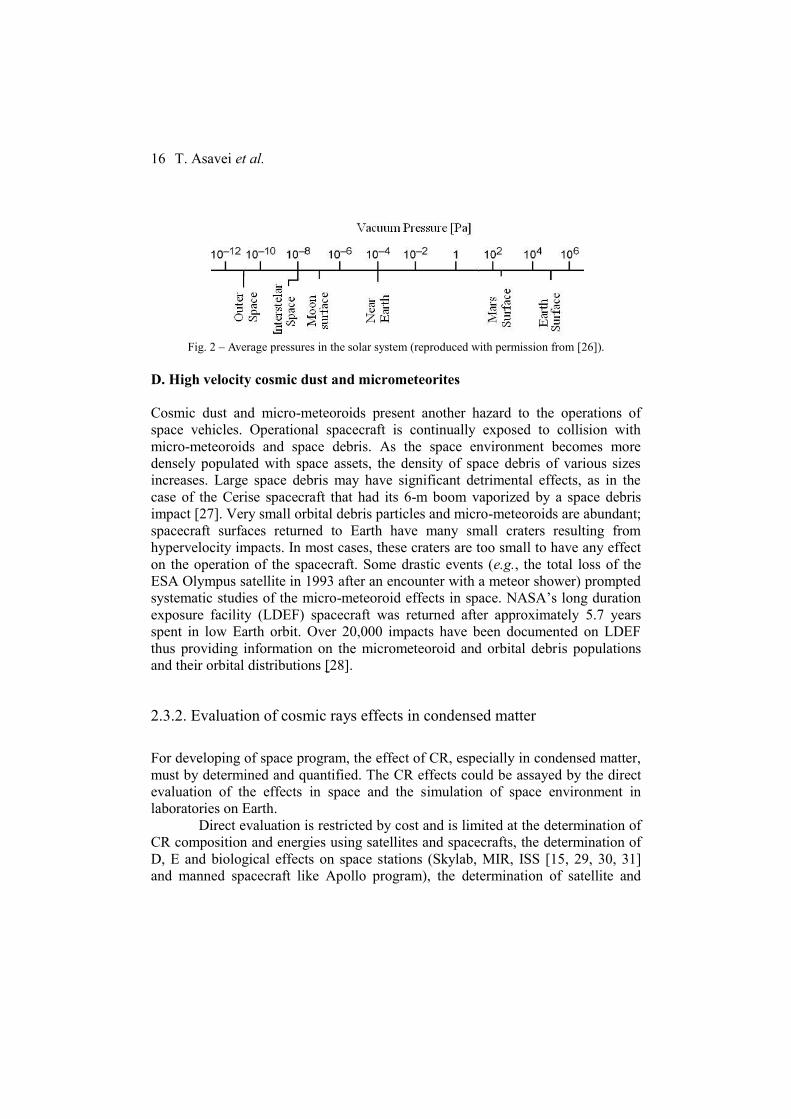
C. High vacuum environment
The outer space vacuum can reaches pressures down to 10-14
Pa. In solar system,
due to molecules accretion phenomenon induced by gravitational forces, the local
pressures values have a relative large distribution. Fig. 2 shows vacuum pressure
distribution in solar system reported by Miyoshi [26].
.
T. Asavei et al.
16
Fig. 2 – Average pressures in the solar system (reproduced with permission from [26]).
D. High velocity cosmic dust and micrometeorites
Cosmic dust and micro-meteoroids present another hazard to the operations of
space vehicles. Operational spacecraft is continually exposed to collision with
micro-meteoroids and space debris. As the space environment becomes more
densely populated with space assets, the density of space debris of various sizes
increases. Large space debris may have significant detrimental effects, as in the
case of the Cerise spacecraft that had its 6-m boom vaporized by a space debris
impact [27]. Very small orbital debris particles and micro-meteoroids are abundant;
spacecraft surfaces returned to Earth have many small craters resulting from
hypervelocity impacts. In most cases, these craters are too small to have any effect
on the operation of the spacecraft. Some drastic events (e.g., the total loss of the
ESA Olympus satellite in 1993 after an encounter with a meteor shower) prompted
systematic studies of the micro-meteoroid effects in space. NASA’s long duration
exposure facility (LDEF) spacecraft was returned after approximately 5.7 years
spent in low Earth orbit. Over 20,000 impacts have been documented on LDEF
thus providing information on the micrometeoroid and orbital debris populations
and their orbital distributions [28].
2.3.2. Evaluation of cosmic rays effects in condensed matter
For developing of space program, the effect of CR, especially in condensed matter,
must by determined and quantified. The CR effects could be assayed by the direct
evaluation of the effects in space and the simulation of space environment in
laboratories on Earth.
Direct evaluation is restricted by cost and is limited at the determination of
CR composition and energies using satellites and spacecrafts, the determination of
D, E and biological effects on space stations (Skylab, MIR, ISS [15, 29, 30, 31]
and manned spacecraft like Apollo program), the determination of satellite and
HPLS–TDR4 Materials in extreme environments at ELI-NP
17
spacecraft malfunction and the correlation with specific space environment
conditions [32, 33].
The most of our knowledge on the CR effects is based on experiments
performed using gamma sources [34], nuclear reactors [17] and particle
accelerators [35–39]. Gamma (Co-60) and neutron sources (nuclear reactors and
Cyclotrons) can be used especially for endurance testing on electronic devices.
Simulation CR effects using low energy particles (below 50 MeV) are less
relevant, especially for space radiation protection [40]. Using new accelerators, the
ions with 1 < Z < 28 should be accelerated up to energies in the range of 0.1–10
GeV/particle, around the energy spectrum of GCR.
An exceptional opportunity to boost research in this field comes from the
construction of the laser-plasma accelerators [41]. This novel radiation sources will
present unique opportunities for CR research, including the ability to produce a
wide panel of particle species (gamma, electrons, protons, medium weight nuclei)
with very high energies.
The ESA and NASA established space exploration programs for the
coming decades, including long-term missions. Development of new programs
implied evaluation of the potential CR effects to microelectronics, optoelectronics,
electrical systems, sensors/ detectors, materials and astronaut crews. The proposal
project aim is to simulate and quantify the space environment effects on condensed
matter. The space stressors analyzed in this proposal are: CR, extreme temperature
and high vacuum pressure.
The main research areas are: dosimetry of radiation fields with similar
characteristics with the CR, fundamental researches in the field area of energetic
and multi-component ionising radiation fields effect on condensed matter as well
as effects of space environment on electronic devices, plastics and composite
materials with applications in future space programs and endurance testing of
experimental models and prototypes.
A. Dosimetry of radiation fields with similar characteristics with the CR
The complex radiation fields generated by interaction of 0.1-1 PW laser beam with
specific targets must be characterised in terms of absorbed dose rate and total
absorbed dose in condensed matter. Adsorbed dose will be quantified by:
- Determination of experimental radiochemical yields (standard chemical
dosimeters like a Fricke ferrous-sulphate, cerium sulphate, free radical
accumulation etc.)
- Inter-comparisons of obtained results due to complexes radiation fields
generated by ELI NP facility and standard sources like Co-60 (using
IFIN-HH DRMR, IRASM and INFLPR infrastructure)
T. Asavei et al.
18
- Calibration of commercial dosimetric films for specific ELI-NP radiation
fields and use in experiments (using IFIN-HH DRMR and INFLPR
infrastructure)
B. Fundamental research in the area of energetic and multi-component
ionising radiation field effect on condensed matter
For understanding of the degradation phenomena, the fundamental processes in
terms of radiation chemistry will be analysed. In this research direction will be
assessed:
- Determination of active unstable chemical species (free radicals and
activated molecules)
- Establish of the chemical fundamental processes in specific case of
multicomponent and energetic ionising radiation fields
Determination of active unstable chemical species will be carried out using ESR
spectrometer (determination of free radicals).
Establish of the chemical fundamental processes Intermediate and final products can be determined using FTIR ATR, Raman and
NMR spectrometers (in the ISO 17025/CNCAN accredited laboratories within
IFIN HH-DRMR and IRASM) and GC MS, HPLC chromatographic techniques (in
the ISO 17025/CNCAN accredited laboratories within IFIN-HH DRMR and
IRASM). Experimental results will be inter-compared with obtained data using
quantum-chemical simulations.
C. Effects of space environment on electronic devices, plastics and composite
materials with applications in future space programs and endurance testing of
experimental models and prototypes
The experiments consist of complex radiation fields exposure of targets, in a sealed
vacuumed enclosure with a cryogenic and thermostatic mantle.
The CR will be simulated by complex radiation fields generated by interaction of
0.1-1 PW LASER beam with specific targets. The radiation fields will consist on
electron (400-600 MeV maximum energy), protons (400-600 MeV maximum
energy), gamma rays (approximately 400 MeV maximum energy) and, if is
possible nucleus with 4 < Z < 14 (approximately 400 MeV maximum energy).
Extreme temperature will be carried out using thermostatic mantle cooled with
liquid He as cryostat agent (about 5 K) and heated with hot air (almost 800 K).

HPLS–TDR4 Materials in extreme environments at ELI-NP
19
The proposed high vacuum pressure experimental condition is in the range
of 10-4
to 10-6
Pa. Depending on the nature of irradiated targets and purposes,
samples will be characterised using:
- Scanning electronic microscope (SEM) and Atomic Force Microscope
(AFM) for identification of micro-structural changes (using INCDFM and
IFIN-HH DFNA laboratories)
- Infrared spectrometer (FTIR) with Attenuated Total Reflectance (ATR) for
identification of chemical modifications (using IFIN-HH DRMR and
IRASM facilities)
- Mechanical testing post-irradiation facilities (using IFIN-HH IRASM
laboratory)
- Functional characteristic in specific case of electronic devices and
optoelectronics (external partners)
D. Degradation of optical crystals and solar cells in space
1. Objective
To use ELI-NP facilities for accelerated testing of the degradation of
optical crystals and solar cells performance in space-like irradiation conditions.
Beyond the scientific experiments, it can be thought as a testing service that ELI-
NP can provide to manufactures of space solar cells or optical components
designed to be used for satellites.
2. Physics case
Due to the high cost of direct investigations in space, the effects of cosmic
radiation on condensed matter can be evaluated with ground based experiments and
ELI-NP facility is a very important candidate. Mainly because the high power
lasers could be a better alternative for reproducing cosmic ray interaction with
condensed matter, since the energy spectrum of laser accelerated particles is similar
to the broad, multi-MeV-scale spectra of natural cosmic radiation, as opposed to
the quasi-monoenergetic spectrum of particle beams in classical accelerators [41].
In the last years at the West University of Timisoara, the crystal growth group has
gained an important experience in the field of growth and characterization of
fluoride type crystals doped with rare earth elements [42, 43], while at the PV
Laboratory an expertise in the monitoring, estimation and forecasting of PV
systems operation has been developed (http://solar.physcis.uvt.ro). Therefore, an

T. Asavei et al.
20
interesting topic that can be covered is the effect of radiation on solar cells, calcium
fluorite and barium fluorite crystals.
Calcium fluoride (CaF2) has much to offer as an optical material. Besides
being highly transparent in the deep UV region, it also has excellent lifetime
stability and relatively high damage threshold in the deep UV. Furthermore, CaF2
has a broad transmission range, from 140 nm to 7.5 µm and beyond, featuring a
low refractive index, removing the need for an anti-reflection coating. Therefore,
CaF2 optical windows are ideal for use as spectrophotometer windows. CaF2 optical
lenses are used in many spectroscopy applications used by NASA in CRISM and
UCIS devices [44]. Likewise, CaF2 grating prisms (grisms) have been successfully
used in the NICMOS camera on board HST [45]. Barium fluoride crystal finds
applications as a transmitting window over a wide wavelength range and as a fast
scintillator involving emission at 195 nm and 220 nm, which is fairly temperature
independent around 300 K [46], used for the detection of X-rays, gamma rays or
other high energy particles. As it is one of the fastest scintillators known, it may be
employed in outer space radiation detection devices. The damage of BaF2 is caused
by the formation of color centers, which cause a self-absorption of the scintillation
light [47] At the Crystal Growth Laboratory at the West University of Timisoara
good optical quality CaF2 and BaF2 crystals can be obtained. For this reason, it is
important to investigate how cosmic radiation exposure influences the defect
structure and optical proprieties of such fluorides, as those employed in the
manufacturing of optical components installed in space satellites.
On the other hand, the solar generator is the only spacecraft subsystem
where electrically active semiconductor devices are directly exposed to space with
a minimum protection. The most influential aspects of the space environment
typically depend on the altitude and inclination of the mission orbit (the main
operational position of satellites are the geostationary orbit (GEO at 36 000 km)
and the low-earth-orbit (LEO at several hundred km altitude with various
inclination).
Trapped electrons and protons have the main contribution to the
degradation of the solar cells efficiency. The main parameter in selection a space
solar cell is the end-of-life (EOL) power output. A variety of novel devices and
materials are under development world-wide: III-V compound solar cells
comprising GaAs on Ge mono-, dual- and triple-junction devices (e.g. [48]). The
current efficiency of the space solar cells is over 30% on space PV market and over

HPLS–TDR4 Materials in extreme environments at ELI-NP
21
44% on research and development lab [49]. As example of solar cells degradation
in space, the table below shows a comparison for the electrical performance for
high efficiency silicon, dual-junction (2J) and triple-junction (3J) commercial space
solar cells covered by thin glass film [50].
Table 1
Electrical performances for various space solar cells
There are two main approaches for evaluating the solar cell degradation in
space [51]. At the US Jet Propulsion Laboratory (JPL) the goal of the approach is
the determination of the normal-incidence 1MeV electron fluence which produces
the same level of damage to the cell as a specified space radiation environment. At
the US Naval Research Laboratory (NRL), the approach is the calculation of the
displacement damage dose for a given mission using the spectral damage
coefficients and the proton and electron spectra incident on the cell.
E. Doped fluoride crystals irradiation for fundamental studies of optical
properties modification
1. Objective
To use of laser plasma accelerated particle radiation from ELI-NP in order
to study the change in optical and dielectric properties of irradiated crystalline
materials with perspective novel laser applications.
2. Physics case
T. Asavei et al.
22
Interest on crystal growth and characterization at the West University of
Timişoara, Faculty of Physics began 40 years ago. The Crystal research laboratory
- growth and characterization is part of the Physics Department of the West
University of Timişoara. The main goal has been to design set-ups and elaborate
technology to obtain and to characterize the crystals. The participation of the WUT
in the ELI collaboration will have a significant impact on the organization research
in the field of crystal growth mainly at two levels:
- At the fundamental research level - the studies of material behavior in
extreme environments (which is a central topic in the ELI-NP proposed
experiments), will give a fundamental understanding of the radiation induced
damage in crystals, taking advantage of the specific properties of laser driven
radiation production, such as ultrashort time scale when the radiation is generated
and the relatively broadband spectrum of radiation, complementary to the
traditional nuclear physics research laboratories [41].
- At the applied research level – the experiments performed under high
energy irradiation processes could be very helpful to obtain new laser materials for
biomedical applications through crystal doping elements charge conversion
radiation mechanisms.
The fluorides type single crystals are an important class of materials in the
modern technologies of the solid state laser elaboration and radiation detectors.
Rare earth doped CaF2 and BaF2 crystals are used as laser active media due to the
well-known good optical properties of the fluoride host and due to the broadband
transition of the different of rare earth ions used as dopants in the crystals. For
example, the Er3+
ion properties have been intensively studied due to the its strong
IR luminescence used for laser resurfacing of human skin [52] and the Yb2+
ions
luminescence (around 314 nm) can be used in psoriasis phototherapy [53–55]. By
doping CaF2 and BaF2 crystalline host with YbF3, both Yb2+
and Yb3+
ions will
coexists in the crystal. Yb2+
ions are responsible for emission in UV and VIS
[56, 57] spectral domain and Yb3+
ions are responsible for the emission in near IR
domain [58, 59].
Modification of ionization states of Yb3+
ions doped in CaF2 crystals can
take place due to γ ray irradiation [60]. Color center formation takes place after
electron irradiation [61]. Also, there exists a possibility that the site symmetry of
the rare earth trivalent ions may change through radiation bombardment by
electron or protons capture from the incoming radiation, which change the
crystalline field around the dopant. Such formed rich multisite structure changes
the crystalline field effects on the impurity ions, generating different electronic
levels; some of these levels may be metastable and give rise to possibly useful laser
applications. The proprieties of rare earth ions doped in CaF2 and CaBa2 after

HPLS–TDR4 Materials in extreme environments at ELI-NP
23
irradiation can be studied using optical and dielectric spectroscopy for the
fundamental understanding of the defect structure formed after irradiation.
2.3.3 Laser-plasma acceleration of particles for radiation hardness testing
High-reliability, radiation-hardened and radiation-tolerant components and
software are of vital importance in space applications, where satellite equipment
implies much more complexity and miniaturization than before. In this context, the
radiation environment used for ground testing should ideally be similar to the
natural environment probed by the satellite, a condition which is difficult to
achieve by traditional accelerator facilities. Recently, it was suggested that high
power lasers could be a better alternative for testing applications [41], since the
energy spectrum of laser accelerated particles is indeed rather similar to the natural
one, as opposed to the quasi-mono-energetic spectrum of accelerated particle
beams in classical accelerators. Moreover, additional advantages are related to the
dimension of the ground experiment volume and the simultaneous availability of
different radiation types. Our progress in filamentary plasma assisted laser
acceleration of the electrons ensures better control of electron beams parameters
(energy, intensity, spectrum, and divergence), by proper synchronization [62],
duration, and intensity of the initial current in the filamentary plasma produced in
different capillary configurations.
2.4 TESTING OF IRRADIATED OPTICAL COMPONENTS
With the advance of ultrashort and ultra-intense laser systems optical components
are now placed in the vicinity of laser driven secondary radiation sources produced
by the interaction of the laser with targets.
It is highly desirable to qualify the modification of the optical properties
(reflectivity, transmission, absorption) as well as the damage threshold
modification for the optical components exposed to such secondary radiation
sources. ELI-NP will be a suitable place for studying such effects since at this
facility a combination of many types of radiation will be generated simultaneously.
At INFLPR, which is located very close to ELI-NP, there is one of the very few
laboratories in the world (ISOTEST) that can qualify the damage threshold of
optical components according to ISO standards.
ISOTEST Laboratory certifies that the Laser Induced Damage Threshold
of a specific sample is tested according to recommendations of the
ISO 21254-1,2,3,4:2011 standards. At the same time ISOTEST Laboratory can
provide laser beam diagnosis. This kind of the laser beam diagnosis includes three

T. Asavei et al.
24
types of measurements: measurement of the energetic characteristic (in the range of
hundreds of nJ up to few J) of the laser beams, temporal characteristic (in the range
of ns and tens of fs) and spatial characteristics of the laser beams. An arrangement
set-up for the laser beam diagnosis is presented in Fig. 3.
Fig. 3 – Experimental set-up for the laser beam diagnosis. LB – laser beam, PB – positioning beam
(generally mirrors for testing the reflectivity, transmission, absorption), BS 1,2,3,4,5 – beam splitters,
D 1,2 – dumpers, PC- personal computer.
The existence of ISOTEST and the specific needs of ELI-NP related to the
qualification of the damage threshold of optical components in the vicinity of laser
driven secondary radiation sources represents an excellent opportunity for this
research direction at ELI-NP.
In the next paragraphs the ISOTEST capabilities of characterizing the
optical surfaces in terms of damage threshold, for nanosecond laser pulses (Fig. 4)
as well as femtosecond laser pulses are briefly described. The experimental set-up
for S-on-1 procedure and feasability study executed with nanosecond laser pulses
is shown in the figure below.

HPLS–TDR4 Materials in extreme environments at ELI-NP
25
Fig. 4 – L, half wave plate; P, thin film polarizer at incident angle 45o; D, dumper for laser beam; OF,
shatter for high energy laser beam; M1; M2, high reflectivity optical mirrors at 45o incident angle;
SP, polarization selector: half wave plate; LC, convergent lens; SH, holografic beam splitter; DT,
detector temporal beam profile; DS, detector spatial beam profile FireWare BeamPro model 2523;
DE1, energy detector laser beam (measurement range 0,1 mJ – 10 J); DE2, energy detector laser
beam (measurement range 0,005mJ – 2 J); ME, two channel energy monitoring; DSP, high speed
digitizer (2 Gsa / s) of 10 bit, with high speed signal processor (FPGA structure); XY, motorised
translation stage system for displacement and positioning the sample in the laser beam; DDS, detector damage sit: module photodiode C10439-03 with active aperture of 10 mm x 10 mm
(HAMAMATSU) and lens with negative aperture; PC, personal computer.
Fig. 4 presents the architecture of the automated system for characterisation of the
optical components and materials in the laser field. The laser beam delivered by a
laser with emission in pulses of nanosecond and femtosecond pulse duration (with
laser beam characteristic stable and reproducible) is set at the desired pulse energy
by means of the variable attenuator controlled by the computer. Then the laser
pulse is sent on the surface of the sample which is hold in the focal plane of the
focusing system.
The sample is mounted on the multiple-axis (xy) micrometric system used
for positioning the test -beam on the sites of the tested sample and also for the
angle of incidence of the test-beam. The polarization state of the laser beam is set
T. Asavei et al.
26
using a half wave plate or quarter wave plate. A small portion of the laser beam is
diverted to the diagnose module, which simultaneously monitor the laser beam
energy (in real time), laser beam profile and the temporal beam profile. The spatial
beam profile is monitored using a camera connected to the personal computer. The
beam profile camera has attached a specialized software which estimates and
calculates the effective area of the beam. The measurement plane of the spatial
beam profile corresponds to the sample plane. The spatial beam profile of the laser
beam measured with the beam profiler is identical with the spatial beam profile on
the surface of the sample. The spatial beam profile is an important factor to
determine the power density applied to the sample.
The temporal beam profile of the nanosecond laser is measured with a fast
photodiode coupled through fiber optics to the oscilloscope. The electrical signal
delivered by the photodiode is sent to the digital signal processor via the
oscilloscope. The digital signal processor sends the information to the personal
computer which commands the irradiation process. For the femtosecond laser, the
temporal pulse duration is a lot more difficult because the time response of the
electro-optic devices (photodiodes, oscilloscopes) is, in the best cases, in the range
of picoseconds.
With the evolution of technology for ultrashort laser systems, some
techniques and advanced devices (FROG, GRENOUILLE, SPIDER and
WIZZLER) have been developed in order to determine the characteristics of
femtosecond laser pulses in the time-frequency domain. These devices process the
laser pulses and reconstruct with a very good accuracy the intensity temporal
profile or the trace of the laser pulses. Temporal beam profile and pulse duration is
very important for a correct evaluation of the power density of the ultrashort laser
pulses applied on the sample, information which is essential in the ISO procedure.
In the cases of the procedures of the ISO measurement/diagnose of the
ultrashort (fs range) laser pulses for the temporal beam profile and pulse duration
an advanced device is used (FROG) which is coupled to the personal computer in
order to control the irradiation process of the sample. The software which runs the
entire procedure of the damage test is designed to control the movement of the
sample along the x and y directions, to attenuate and to block the laser pulses, to
count the site distribution and the number of pulses applied on each site until the
damage has occurred. At the same time the software will detect the optical damage
of the site exposed to the laser pulses. The software will also make a statistical
analysis of the experimental data and it will calculate the damage probability of the
tested sample versus the energy density of the laser pulse. After the automated
measurement procedures, the software will automatically generate the
measurement test report.
HPLS–TDR4 Materials in extreme environments at ELI-NP
27
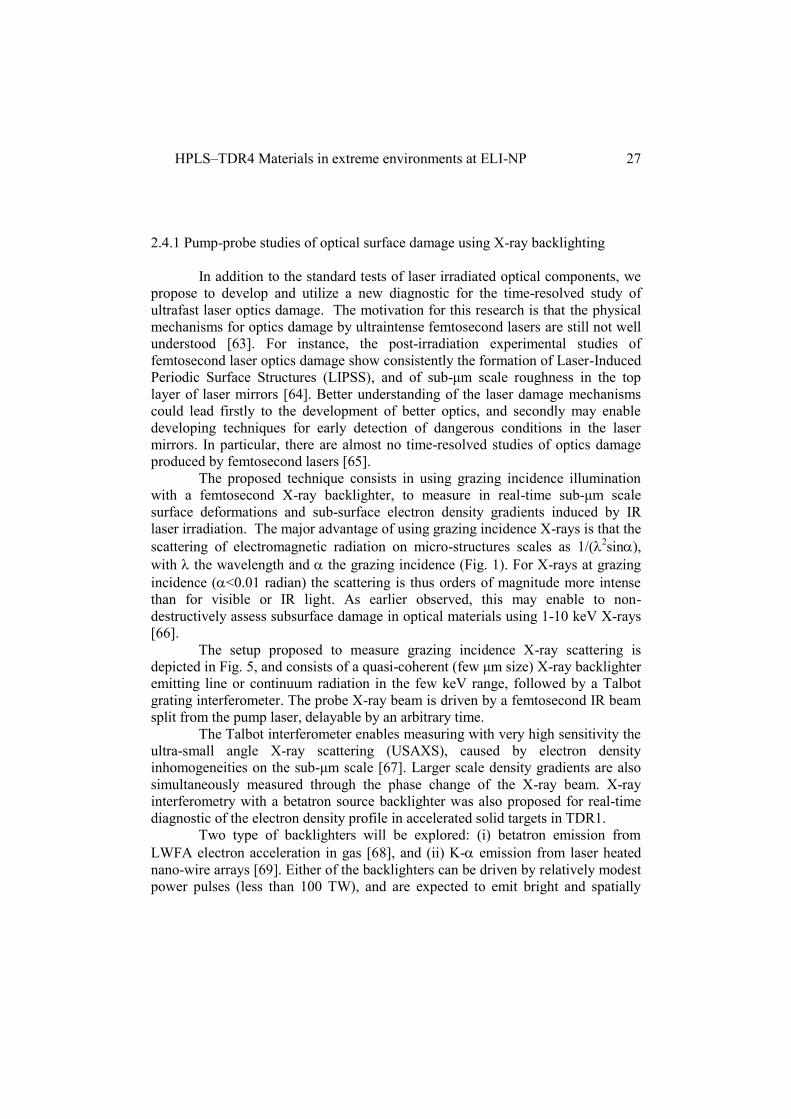
2.4.1 Pump-probe studies of optical surface damage using X-ray backlighting
In addition to the standard tests of laser irradiated optical components, we
propose to develop and utilize a new diagnostic for the time-resolved study of
ultrafast laser optics damage. The motivation for this research is that the physical
mechanisms for optics damage by ultraintense femtosecond lasers are still not well
understood [63]. For instance, the post-irradiation experimental studies of
femtosecond laser optics damage show consistently the formation of Laser-Induced
Periodic Surface Structures (LIPSS), and of sub-μm scale roughness in the top
layer of laser mirrors [64]. Better understanding of the laser damage mechanisms
could lead firstly to the development of better optics, and secondly may enable
developing techniques for early detection of dangerous conditions in the laser
mirrors. In particular, there are almost no time-resolved studies of optics damage
produced by femtosecond lasers [65].
The proposed technique consists in using grazing incidence illumination
with a femtosecond X-ray backlighter, to measure in real-time sub-μm scale
surface deformations and sub-surface electron density gradients induced by IR
laser irradiation. The major advantage of using grazing incidence X-rays is that the
scattering of electromagnetic radiation on micro-structures scales as 1/(2sin),
with the wavelength and the grazing incidence (Fig. 1). For X-rays at grazing
incidence (<0.01 radian) the scattering is thus orders of magnitude more intense
than for visible or IR light. As earlier observed, this may enable to non-
destructively assess subsurface damage in optical materials using 1-10 keV X-rays
[66].
The setup proposed to measure grazing incidence X-ray scattering is
depicted in Fig. 5, and consists of a quasi-coherent (few μm size) X-ray backlighter
emitting line or continuum radiation in the few keV range, followed by a Talbot
grating interferometer. The probe X-ray beam is driven by a femtosecond IR beam
split from the pump laser, delayable by an arbitrary time.
The Talbot interferometer enables measuring with very high sensitivity the
ultra-small angle X-ray scattering (USAXS), caused by electron density
inhomogeneities on the sub-μm scale [67]. Larger scale density gradients are also
simultaneously measured through the phase change of the X-ray beam. X-ray
interferometry with a betatron source backlighter was also proposed for real-time
diagnostic of the electron density profile in accelerated solid targets in TDR1.
Two type of backlighters will be explored: (i) betatron emission from
LWFA electron acceleration in gas [68], and (ii) K- emission from laser heated
nano-wire arrays [69]. Either of the backlighters can be driven by relatively modest
power pulses (less than 100 TW), and are expected to emit bright and spatially
T. Asavei et al.
28
coherent, femtosecond duration X-rays. The coherence can be improved using a
third grating close to the backlighter. A HHG emission based XUV backlighter can
also be considered.
Fig. 5 – Layout of IR pump / X-ray probe diagnostic for time-resolved optical damage studies. G1
and G2 are μm-period transmission and absorption gratings, respectively.
The optical surface to be studied will be irradiated with a low intensity
(less than 1 J/cm2), large area IR beam, simulating the operating conditions of the
mirrors at ELI-NP. The pump power density will be varied and its effects on the
mirror surface measured in real-time, with μm spatial resolution. By varying the
delay of the X-ray probe with respect to the IR pump it will be also possible to
study the dynamics of damage formation. Lastly, another benefit of the proposed
technique is that due to the grazing incidence of the X-rays, it will be possible to
probe a large area (several cm2 at least), in a single shot.
Using this method we hope to develop a predictive understanding of the
laser damage mechanisms to the ELI-NP mirrors, and possibly a real-time method
for detecting low damage levels, before they can compromise the mirror and
subsequent optics.
2.5 Studies of materials for nuclear facilities
Energy production using fusion plasma is an expected goal and a research
domain very well explored at the international level. In present the most reliable
method to produce fusion nuclear reactions is those of the hot plasma, magnetically
confined in a tokamak type reactor. The fusion device ITER (International
Thermonuclear Experimental Reactor), to be operated at Cadarache, France is,
probably the largest scientific project started ever. An important problem still
unresolved is the material composition of the reactor main chamber (the first wall),
materials to resist to the high energy fluxes of 10-100 MW/m2. These energy fluxes
appear during the plasma instabilities, when the magnetic field lines are losing the
stable configuration and the ionized plasma particles having over 10 eV
temperatures are directed toward the first wall. As instabilities examples we
Pump IR laser
Probe X-ray beam
FemtosecondX-ray backlighter
Optical component
Talbot interferometer
G1
G2X-ray cameraIR backlighter driver

HPLS–TDR4 Materials in extreme environments at ELI-NP
29
mention the edge localized modes (ELMs), disruptions, etc. Accordingly, for the
wall protection was proposed to use tungsten plates in the divertor region, knowing
the desired properties; low sputtering rate and the high melting temperature. The
other materials are carbon (as form of CFC- carbon fiber composite) and beryllium
(a light element with a relative high melting temperature – 1551.15 K). However,
the behavior of W, C and Be at high flux energies is not yet fully understood and is
intensively investigated.
2.5.2 Direct laser irradiation of first wall materials
Preliminary experiments on direct exposure of first wall materials to fs laser have
been performed. Irradiation of C, W and Be targets was performed by focusing an
800 nm femtosecond laser with the incident energy of 6.3 mJ, pulse duration of
70 fs at a repetition rate of 10 Hz on the target [70]. After irradiation the samples
were investigated by means of SEM. Different morphologies of the irradiated areas
were observed, depending on the target material (as seen in Fig. 6).
Fig. 6 – SEM image of a W
sample after direct irradiation
SEM image of a C sample after
direct irradiation
SEM image of a Be sample after
direct irradiation
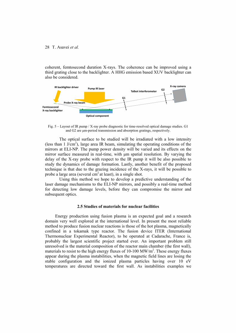
2.5.3 Laser-driven plasma effects on first wall materials
Indirect irradiation of solid targets has been performed, by producing plasma close
to the target (femtosecond filamentation in air). The plasma-target interaction has
been observed by SEM analysis of the samples as seen in Fig. 7 [70].
T. Asavei et al.
30
Fig. 7 – Plasma effect on the W sample Plasma effect on the C sample Plasma effect on the Be sample
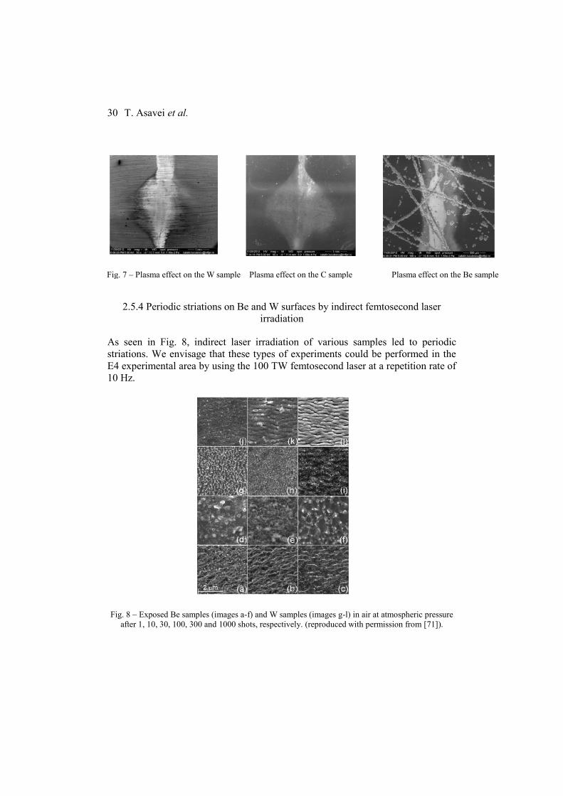
2.5.4 Periodic striations on Be and W surfaces by indirect femtosecond laser
irradiation
As seen in Fig. 8, indirect laser irradiation of various samples led to periodic
striations. We envisage that these types of experiments could be performed in the
E4 experimental area by using the 100 TW femtosecond laser at a repetition rate of
10 Hz.
Fig. 8 – Exposed Be samples (images a-f) and W samples (images g-l) in air at atmospheric pressure
after 1, 10, 30, 100, 300 and 1000 shots, respectively. (reproduced with permission from [71]).
HPLS–TDR4 Materials in extreme environments at ELI-NP
31
2.6 BIOLOGICAL SYSTEMS UNDER IRRADIATION
The main objective of the proposed facility development described here is the
investigation in the fields of bio-physics, radiobiology and biomedical studies,
particularly the investigation of the interaction of biological systems with tunable
multi-component, multi-energetic radiation, with relevance for improving biologic
radioprotection in space missions, and for radiobiology studies with relevance in
cancer treatment, especially for resistant cells, using the unique ELI-NP laser-
generated radiation. The ELI-NP Experimental area E5 has the capability to
operate two laser beams simultaneously and thus can provide two different types of
radiation, some of them multi-component and multi-energetic, from solid or
gaseous targets. The radiation beams can be superimposed on a biological sample
or applied with a short delay between them to mimic the exposure to cosmic
radiation.
2.6.1. Areas of biomedical research at ELI-NP
A. The impact of galactic cosmic radiation (GCR) on biological systems
The new experimental development will allow achievements that will provide a
comprehensive scientific understanding of the effect of multi-component radiation
on cells and organisms and an improvement of the biological radioprotection
measures for astronauts in space mission, and for the airline crews.
The following objectives will be pursued:
– To establish an advanced “ground-based laboratory model” mimicking the
complex high-energy and charge particle environment in space (GCR)
– To draw comprehensive biological networks of molecular events which
might be altered by GCR, along with the corresponding repair-mechanisms
– To (re)classify the biological hazards due to space radiation exposure
based on these molecular networks
– To identify molecular markers which underlie the biological susceptibility
to the damaging effects of GCR, relevant for crew selection
– To develop biosensors for real-time biological monitoring of astronauts
during space flight
– To (re)shape the biological radioprotection system for astronauts and air
crews, taking into account the subtle functional changes possibly induced
T. Asavei et al.
32
by repeated or long-term exposure to the complex, although low-dose
cosmic radiation
– To develop therapies for preventing or counteracting the deleterious effects
of chronic exposure to cosmic radiation.
B. Development of new approaches in biomedical and biomolecular studies for
cancer treatment
The ELI-NP facility will have two 1 PW laser beams in the experimental area E5,
which will further provide multi-component and multi-energy radiation beams.
Thus it will have the capability to offer unique experimental conditions allowing
biomedical studies which could deliver a new approach in cancer treatment and the
associated medical technologies, to improve the efficacy by attacking cancer cells
with highly targeted multi-component ionizing radiation and aiming to overcome
the resistance to treatment of particular cancer cells.
The following objectives will be pursued:
– Using the high power laser at ELI-NP, to obtain highly-controlled and
tunable multi-component radiation beams to be used for cellular and tissue
irradiation
– To define at molecular level the mechanism of action of this complex
radiation on normal and diseased cells/tissue, aiming to increase survival
whilst reducing the treatment side effects by enhancing the radiation effect
with nanoparticles
– To develop targeted theranostic strategies in cancer by joining this
complex radiation approach with chemotherapy/immunotherapy and
concomitant 3D imagistic monitoring of tumors
– To develop co-therapies for counteracting the deleterious action of the
complex radiation, by specifically targeting the molecular events
underlying the direct deleterious action of irradiation.
2.6.2. Motivations
A. Beyond state-of-the-art study
Due to the extensive space missions and current plans for permanent planetary
bases, the issue of space radiation protection against Galactic Cosmic Rays (GCR),
solar energetic particles (SEP), and trapped energetic particles in a planetary
magnetic field, combined with a stressful microgravity environment, is becoming
increasingly important.

HPLS–TDR4 Materials in extreme environments at ELI-NP
33
GCRs consist of highly energetic nuclei, predominately protons and He, but also
trace amounts of C, O, Ne, Si, Ca, and Fe ions. Particle energies can range from
100 MeV to 10 GeV per nucleon. Although the high charge and energy (HZE)
nuclei are in trace amounts, they can cause more damage than protons, since they
are more highly ionizing. Although typically being in the low-dose range, they are
chronic and can significantly increase with solar events. Furthermore, GCR and
SEP impinging on the shielding material, atmosphere, or surface of a planet can
produce secondary radiation, including energetic neutrons [72].
This complex charged particle environment in space raises considerable challenges
with regard to potential health consequences that can impact mission design and
crew selection. The limited knowledge of the biological effects of different ions, in
isolation and in combination, is a particular concern because the risk uncertainties
are very high for both cancer and non-cancer late effects [73].
Although intensive research was done in this field, an obvious conclusion could not
be drawn, mainly because the existing laboratory models of GCR were far from
reflecting the complexity of charged particles in space, due to technological
limitation. From the biological point of view, the published studies were only
scattered parts of a complex puzzle, which could not be put together due to
important experimental design differences at the level of radiation type, dose and
irradiation geometry, cells and biological endpoints, etc).
Maalouf et al. [74] reviewed the knowledge evolution regarding the biological
effects of space radiation on human cells, and the new investigations in this area of
research are required by the complexity of spacecraft geometry and by the variety
of used materials. Also the knowledge regarding the cellular response to complex
radiation is fragmented and requires a comprehensive genomic and proteomic
studies.
Regarding the exposure to low-dose radiation [74] this could be considered a useful
model for the radiation environment of other planets with thinner atmospheres and
weaker magnetic fields.
The ELI-NP facility will have the capability to respond to the challenge of
generating a complex, multi-component and multi-energetic radiation which will
closely mimic the GCR. We emphasize herein that synergistic biological effects of
GCR components, along with thermal stress, hyper-oxygenation and microgravity,
are expected. Therefore, to create such complex conditions at least at the level of a
tightly controlled multi-component radiation is mandatory for obtaining reliable
preclinical data regarding the biological effects of GCR on humans.

T. Asavei et al.
34
The ELI-emerging complex radiation will be modeled according to the data
collected during space missions (World Data Center for Cosmic Rays) to mimic as
realistic as possible the stressful conditions to which astronauts are exposed.
Preclinical investigations to be developed at ELI-NP and partner institutions, as
part of a comprehensive molecular study [75, 76] using genomics and proteomics
approaches will be performed such to:
– To document early and late health risks associated to chronic or
repeated exposure to GCR, which may guide the evidence-based
development of radioprotection measures, including new shielding
materials and strategies.
– To discover specific biomarkers of susceptibility/resistance to GCR,
which will sustain a medically rational selection of astronauts.
– To establish biological endpoints relevant for monitoring the exposed
space crew (real-time monitoring during the space mission and long-
term monitoring for potential late effects).
– To develop biosensors for real-time biologic monitoring of the space
crew, which should be highly sensitive to molecular markers or
processes which are altered rapidly by the ionizing radiation.
– To develop targeted therapies to counteract the deleterious action of
GCR, by specifically addressing molecular networks responsible for
the spreading of the damaging effects of ionizing radiation. In
example, limitation of oxidative stress by transient activation of
antioxidant elements transcription might provide protection against the
damaging effects of GCR [77]. As shielding space radiation is
seemingly quite challenging, the advances in biomedicine may reveal
some more tools for radiation protection [78].
HPLS–TDR4 Materials in extreme environments at ELI-NP
35
B. Exploring new approaches for improving treatment in cancer
Ionizing radiation is harmful in terms of risks to health, mainly due to its role as a
carcinogen, but non-cancer effects were also recently demonstrated [79].
On the other side, ionizing radiation proved beneficial action in various diagnostic
and therapeutic procedures in cancer (Table 2). Historically, there are three main
types of irradiation: external beam irradiation or teletherapy; brachytherapy or
sealed source irradiation, in which radiation is delivered internally inside or next to
the diseased tissue; systemic radioisotope therapy or unsealed source irradiation, in
which the radioisotopes are administered by infusion/oral ingestion.
Particle irradiation uses subatomic particles (electrons, protons, neutrons, carbon
ions, alpha particles, and beta particles) to produce damaging ionization in tumor
tissues. When a charged particle enters a medium the energy it deposits is
approximately inversely proportional to the square of its velocity. Accordingly, as
the particle slows, the probability of causing ionization events increases and a rapid
accumulation of ionization events occurs in the irradiated tumor. The physical
depth-dose distribution of particle beams in tissue is characterized by a small
entrance dose and a distinct maximum (Bragg peak) near the end of range, with a
sharp fall-off at the distal edge [80]. The particles have very little energy beyond
the Bragg peak, which is seen at a tissue depth that is proportional to the energy of
the particle [81]. Taking full advantage of the well-defined range and the small
lateral beam spread, modern scanning beam systems allow delivery of the dose
with millimeter precision.
Examples of particle irradiation treatments:
– Neutron beams are used for some cancers of the head, neck, prostate and for
certain inoperable tumors. Because neutrons can damage DNA more than
photons, effects on normal tissue can be more severe [82] but still show great
promise in inoperable salivary gland cancers.
– Electron beams, produced by linear accelerators, are negatively charged, have
a low energy level and do not penetrate deeply into the body. This type of
radiation is used mostly to treat skin, tumors, and lymph nodes that are close
to the surface of the body [83].
– Proton beams cause less damage to tissues, but are very good at killing cells
at the end of their path. Therefore, proton beams are able to deliver more
radiation to the tumor, whilst causing fewer side effects to normal tissues
[84]. Protons therapy is used routinely for certain types of cancer, but it
requires highly specialized equipment and is not widely available.

T. Asavei et al.
36
– Carbon ion radiation, are heavy particles which exhibit an enhanced
biological effectiveness in the Bragg peak region, caused by the dense
ionization of individual particle tracks, resulting in reduced cellular repair.
This makes them particularly attractive for the treatment of radio-resistant
tumors localized near organs at risk [85, 86]. This type of radiation is only
available in a few centers in the world and is used in treating cancers that do
not usually respond to radiation.
Table 2
Irradiation procedures and the corresponding delivery technologies
Technique Delivery Technology
Image Guided Radiotherapy
(IGRT) 2D IGRT, 3D IGRT, MRI guided IGRT
Intensity Modulated
Radiotherapy (IMRT)
Linac based IMRT, VMAT ,
Tomotherapy
Stereotactic Radiation Treatment
Linac based SRS, Gamma Knife,
Tomotherapy
Cyber Knife
Advanced Imaging for Treatment
Planning
4DCT, MRI – CT Fusion, PET – CT
Fusion
Motion Management Gated Radiotherapy, Tumor Tracking
Adaptive Radiotherapy Adaptive Radiotherapy Procedures and
Processes
Particle Therapy
3D Conformal Proton Therapy, Intensity
Modulated Proton Therapy, Heavy Ion
Therapy
Brachytherapy
Electronic Brachytherapy, Permanent
LDR Implant, Directional LDR
Permanent Brachytherapy
The irradiation technique proves to have important limitations, due to:
– Resistance to irradiation of particular cancer cells, mainly cancer stem cells
(CSC) which are responsible for disease recurrence, having the exclusive ability
to self-renew, differentiate into diverse type of progeny cancer cells, and initiate
tumors [87]. Recently, it was shown that the irradiation itself can induce the
development of CSC [88]. The radio-resistance of CSC resides in enhanced
repair mechanisms, upregulated cell cycle control and increased free radical
scavenging. Moreover, CSC are apparently also involved in memorizing and
spreading of radiation-induced genomic instability [89] Protons preferentially

HPLS–TDR4 Materials in extreme environments at ELI-NP
37
target CSC and promising results were obtained by internal irradiation with 64
Cu-ATSM [90].
– Significant side-effects, more or less associated to the uncontrollable radiation-
induced bystander and abscopal effects [91, 92]. The symptoms of late effects
can be moderate-to-severe and show worsening over time, even 20–34 years
after irradiation. These lesions often include fibrosis, tissue necrosis, atrophy,
vascular damage and, in very severe cases, radiation-induced cancers [93].
Despite advanced treatment modalities, cancer still plagues us as a largely
incurable disease, especially for the patients who detect the malignant neoplasm at
a late stage. In addition, frequent metastasis and recurrence further frustrates even
the best treatments currently available.
2.6.3. Proposed experimental investigations
A. Multi-modal irradiation approach
For responding to the need to overcome resistance to irradiation, taking into
account the tumor intrinsic heterogeneity [94], we propose a research direction at
ELI-NP that will investigate a novel strategy by multi-modal attack of cancer cells,
with:
– Highly targeted and tunable multi-component, multi–energetic ionizing
radiation, laser-generated, to be administered to the diseased tissue either
successively or simultaneously, each component being efficient for
destroying particular types of cancer cells within a heterogeneous tumor.
This new approach has at least theoretically the potential to kill all types of
cancer cells, but combination with chemotherapy is not excluded.
Concomitantly, its multi-component nature raises the risk of important
side-effects deriving from an increased dose delivered to the body.
Therefore we should focus from the beginning on precisely targeting the
irradiation, by using advanced imaging techniques for obtaining an
accurate 3D image of the tumor to guide a clear-cut irradiation. For
improving the imaging component of the multi-modal irradiation approach,
biocompatible nanoparticles could be used as contrast agents, such as
super-paramagnetic nanoparticles for MRI [95] or gold nanoparticles for
X-ray imaging [96].
– Radio-sensitizers, for increasing the sensitivity of cancer cells to ionizing
radiation, thus decreasing the irradiation dose and consequently the
potential adverse effects [97].

T. Asavei et al.
38
Radio-sensitizations might be achieved by a) altering cancer cell
metabolism (i.e. with nucleoside analogs); b) transient lowering of the
antioxidant response of the tumor for sustaining the cytotoxic mechanisms
of irradiation (oxidative stress).
We emphasize that nanoparticles which increase the power of existent
imagistic methods, such as gold nanoparticles, were recently proved to
have radiosensitizing properties [98].
– Radio-protectors, for limiting the effects of radiation-induced oxidative
stress on normal tissues; recently, evidence exists that modification of key
molecular targets to induce biological changes in the host can protect tissue
from radiation damage.
– Immune-modulators, for protecting or reinforcing the host ability to fight
against tumor cells, using conventional methods or emerging ones, such as
intervention of the intestinal microbiota [99].
We emphasize herein that the very same nanoparticles used for improving tumor
imaging, could be functionalized and used as drug carriers for radiosensitizers,
chemotherapeutic agents and/or immunomodulators. Delivery through a carrier can
significantly increase the efficacy of a drug by its tumor-specific targeting utilizing
the enhanced permeability and retention effect [100].
Such a multi-modal irradiation strategy is a theranostic approach [101],
joining imagistic and multi-modal treatment within a single procedure, which will
allow for an efficacious personalized procedure [102] based on the patient’s
disease variant, characterized by a particular molecular profile of the patient and of
the tumor. Besides the proof-of-concept-study, extensive molecular research should
be done for assessing markers which will guide the selection of patients which will
mostly benefit from this multi-modal strategy such as biomarkers which
characterize the particular response of cells/tissues to the multi-modal irradiation
(type of tumor cell death, repair mechanisms, response to oxidative stress) and
biomarkers which define the susceptibility/resistance of various cancer and normal
cells/tissues to this particular approach the impact of the multi-modal irradiation on
the anti-tumor immune response, also taking into account that radiation-killed
tumor cells might release tumor antigens which might trigger an efficient immune
response against the tumor [103]. Such mechanistic studies will also draw the lines
for developing co-therapies to counteract the deleterious effect of ionizing radiation
in healthy tissue.
B. Molecular mechanisms underlying the deleterious action of radiation on
biological systems

HPLS–TDR4 Materials in extreme environments at ELI-NP
39
The molecular mechanisms involved in radiation-induced responses are complex,
and multiple complementary approaches are needed to understand the overall
reaction process.
Preclinical investigations in the above mentioned studies will go beyond
conventional biomedical methods and procedures for toxicological/treatment
efficacy assessments. We will take advantage of the latest technological and
conceptual gains provided by proteomics [104] and genomics [105] to generate a
large volume of data regarding the molecular basis of the biological effects exerted
by ionizing radiation on a large panel of human cells, of cellular responses and
individual susceptibility to this challenge. Data will be further integrated into
complex biological pathways networks, which will be finally validated in animal
models.
The extensive molecular study we are proposing aims to respond to challenging
issues regarding the exposure to low-dose radiation, as defined in the Strategic
Research Agenda of the Multidisciplinary European Low Dose Initiative
(MELODI) [79] such as dose and dose rate dependence of cancer risk, non-cancer
effects and individual radiation sensitivity.
The new experimental approach regarding biological effects of space-like radiation
that will be developed at ELI-NP will bring innovation and valuable new
preclinical data regarding potential synergistic effects exerted by a multi-
component radiation, focusing on the molecular basis of the interaction and the
corresponding cell/tissue response.
Important biomedical issues to be tackled at molecular level are [79]:
– The nature of the normal target cells for the radiation-induced deleterious
effects (such as stem cells which may have specific responses to radiation
and are thus involved in radiation-induced carcinogenesis).
– The contribution of DNA damage / mutational processes and epigenetic
modifications (specific genes and genetic regulatory mechanisms can
contribute to refining novel risk extrapolation models and the identification
of radiation relevant biomarkers).
– The influence of cell micro-environmental and systemic processes, such as
inflammatory reactions and effectiveness of both adaptive and immune
surveillance.
– The molecular vehicles propagating radiation-triggered signals, such as
soluble molecules (cytokines, oxidized molecules) and/or gap junction (by-
stander effect [106, 107]).
T. Asavei et al.
40
– The nature of oxidative stress triggered in biological structures by
radiation, its involvement in signal transduction [108] and cell/tissue
functionality [109]; the specific anti-oxidant response developed by various
types of cells following irradiation [110] which might a key element of
individual resistance to irradiation.
– The (epi)genomic profile which underlies the sensitivity of particular cells
and individuals to ionizing radiation (whilst being a benefit in cancer
treatment, radiosensitivity may be the cause of dramatic side-effects of
even low dose-radiation).
By characterizing the molecular profile of the interaction between multi-
component radiations and biological systems, valuable information will be
obtained to foster the development of targeted therapies to counteract the
deleterious action of ionizing radiation on normal tissues. Special emphasis will be
given to subtle effects of low-dose radiation, which have apparently no immediate
consequences, but which may alter homeostasis in the long-term and have
important health consequences.
2.6.4. Multidisciplinary concerted approach
Such vast biological data can be obtained and integrated only by a sustained
programmatic research effort, joining international expertise and state-of-the-art
facilities for building a rational study based on concerted actions, unified protocols
and a unique database.
By the very nature of the proposed research to be developed at ELI-NP and in
partner institutions, multidisciplinary teams should be involved, joining at least the
expertise of physicists, engineers, mathematicians, biologists, biochemists,
biophysicist, physicians etc. ELI-NP should build the frame of multidisciplinary
cooperation, by sustaining and promoting the dialogue between experts with
various expertise.
3. TECHNICAL PROPOSAL
3.1. EXPERIMENTAL AREA
The experiments envisaged in this TDR will take place in the E5 experimental area,
except the tests on the irradiated optical components which will take place in the

HPLS–TDR4 Materials in extreme environments at ELI-NP
41
E4 experimental area. In the figure below the two experimental areas (E4 and E5)
are shown with respect to the laser room. E4 will host the two arms of the 0.1 PW
laser with a repetition rate of 10 Hz, while in E5 the 1 PW lasers (25 J of energy
with a pulse duration of 25 fs, at a repetition rate of 1 Hz) will be accommodated.
Fig. 9 – E4 and E5 experimental areas.
The experiments proposed at E5 will be irradiation of materials with secondary
radiation beams for example electron beams, proton beams, neutron beams; we can
foresee electron production by means of laser irradiation of gaseous targets and
proton and neutron production by means of laser-solid targets interaction. A
scheme of an interaction chamber in E5 that will allow production of the above
mentioned laser-driven secondary beams is shown below.

T. Asavei et al.
42
Fig. 10 – Schematic of a proposed interaction chamber in E5 for laser-driven secondary beams.
A CAD design of the experimental area E5 is shown in the figure below:
Fig. 11 – CAD design of E5 experimental area.
The ELI-NP E5 area will have the experiment monitoring and control systems
architecture similar to the High Power Laser System of ELI-NP. The architecture is
based on TANGO, which will permit local distributed control of the equipment and
additional clients to remotely supervise/control the experiment.

HPLS–TDR4 Materials in extreme environments at ELI-NP
43
This solution will allow a standardization of the control systems inside ELI-NP,
while providing easy maintenance, better security, better logging and interfacing
methods between the experimental area and the HPLS.
A dedicated UserRoom will be used to remotely control from outside the
E5 area the equipment as the experiment is running. A TANGO framework will be
developed to link the experimental area to the UserRoom using a dedicated client –
server architecture that will allow maintenance and upgrades to be performed
without interacting with other systems.
A data storage server will be available for short term experimental data
saving and this shall benefit in general from dedicated data busses, separated from
the client – server TANGO architecture that controls and monitors the equipment
itself, in order to achieve the highest data throughput. Dedicated TANGO servers
are envisaged to interface the equipment necessary in the experiment such as focal
spot monitoring, solid target alignment, solid target manipulation, target insertion
system, delay generators, monitoring CCDs and vacuum system for the E5
interaction chamber.
The above equipment will have a Human Machine Interface able to locally
(from inside the interaction area) or remotely (from the user room) monitor and
control the parameters needed to run the equipment and the experiment. Other
equipment that do not allow an easy TANGO binding will be remotely controlled
using its proprietary software through a remote desktop (or similar) connection.
The user room will also provide to the users information regarding the HPLS
parameters. However, the laser parameters will be controlled from the HPLS
control room by the operators, from personnel and machine safety reasons.
3.1.1. Sample manipulation
For the experiments involving solid targets, the sample manipulation will be based
on a load-lock system designed and developed in collaboration with the National
Institute of Cryogenics and Isotopes ICSI Ramnicu Valcea. As seen in the figure
below, the samples will be loaded on top of the chamber onto the xyz translation
stage in the interaction chamber.
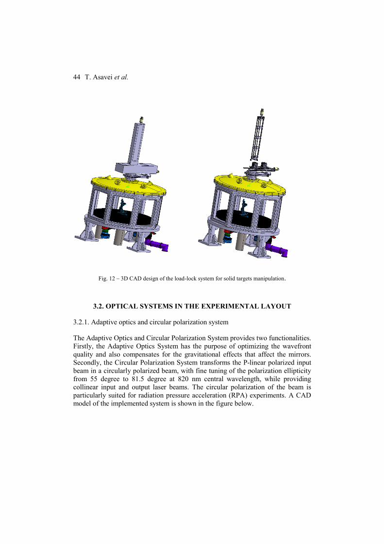
T. Asavei et al.
44
Fig. 12 – 3D CAD design of the load-lock system for solid targets manipulation.
3.2. OPTICAL SYSTEMS IN THE EXPERIMENTAL LAYOUT
3.2.1. Adaptive optics and circular polarization system
The Adaptive Optics and Circular Polarization System provides two functionalities.
Firstly, the Adaptive Optics System has the purpose of optimizing the wavefront
quality and also compensates for the gravitational effects that affect the mirrors.
Secondly, the Circular Polarization System transforms the P-linear polarized input
beam in a circularly polarized beam, with fine tuning of the polarization ellipticity
from 55 degree to 81.5 degree at 820 nm central wavelength, while providing
collinear input and output laser beams. The circular polarization of the beam is
particularly suited for radiation pressure acceleration (RPA) experiments. A CAD
model of the implemented system is shown in the figure below.
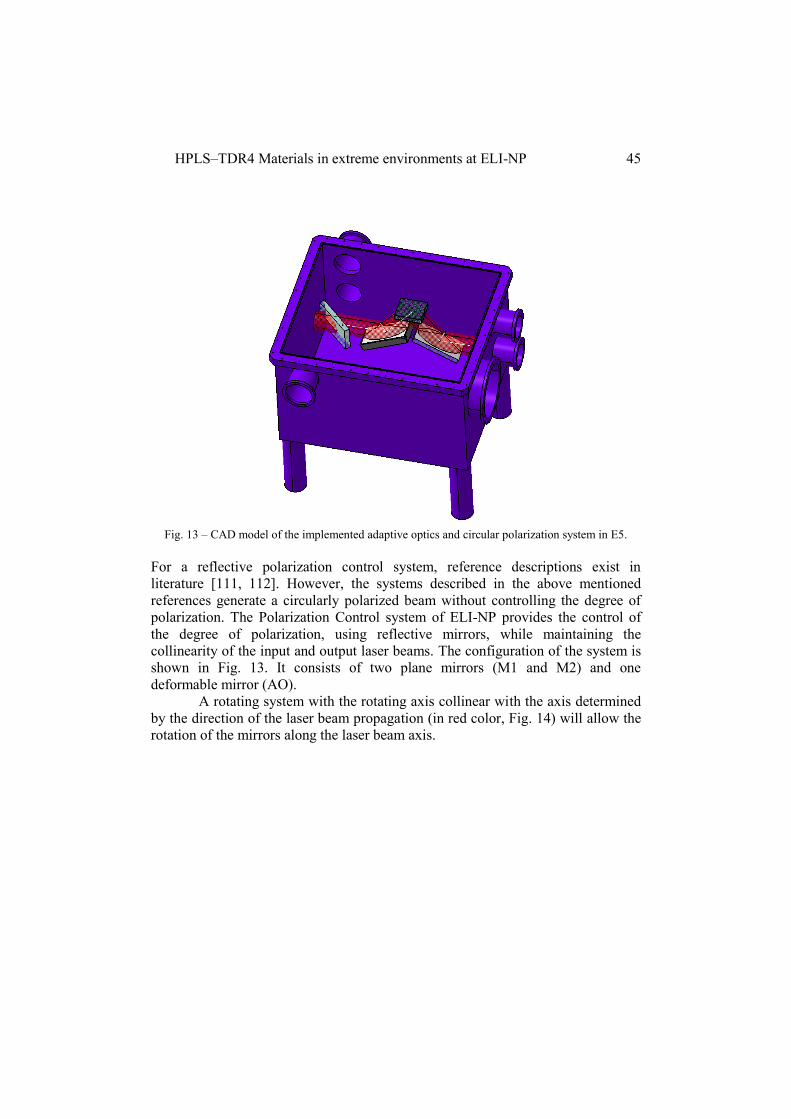
HPLS–TDR4 Materials in extreme environments at ELI-NP
45
Fig. 13 – CAD model of the implemented adaptive optics and circular polarization system in E5.
For a reflective polarization control system, reference descriptions exist in
literature [111, 112]. However, the systems described in the above mentioned
references generate a circularly polarized beam without controlling the degree of
polarization. The Polarization Control system of ELI-NP provides the control of
the degree of polarization, using reflective mirrors, while maintaining the
collinearity of the input and output laser beams. The configuration of the system is
shown in Fig. 13. It consists of two plane mirrors (M1 and M2) and one
deformable mirror (AO).
A rotating system with the rotating axis collinear with the axis determined
by the direction of the laser beam propagation (in red color, Fig. 14) will allow the
rotation of the mirrors along the laser beam axis.

T. Asavei et al.
46
Fig. 14 – Side view of the circular polarization system.
The first plane mirror (M1) has one degree of freedom (rotation, as seen in Fig.
14), while the second one (M2) has both translation and rotation. The deformable
mirror (AO) has one degree of freedom for translation hence allowing fine tuning
of the degree of ellipticity.
Fig. 15 – Schematic view of the system along the laser propagation direction, showing its working
principle.

HPLS–TDR4 Materials in extreme environments at ELI-NP
47
3.2.2. Plasma mirror system
In order to improve the temporal contrast of the 1 PW laser pulse after the
compressor, a double plasma mirror system will be used, as schematically shown in
the figure below.
Fig. 16 – Schematic of a double plasma mirror system to be used in the E5 experimental room.
With such a system a high contrast of 1011
was achieved at 6 ps before the main
pulse [113]. The double PM scheme is composed of two flat mirrors, two off-axis
parabolic mirrors and two dielectric plates with antireflection (AR) coating. The
off-axis parabolic mirror (F/10) will be designed for an angle of incidence of 5
degrees.
The two dielectric plates acting as plasma mirrors will be accommodated in
a separate vacuum chamber. Typically, the improvement of contrast is around 2
orders of magnitude for one dielectric plate with AR coating.
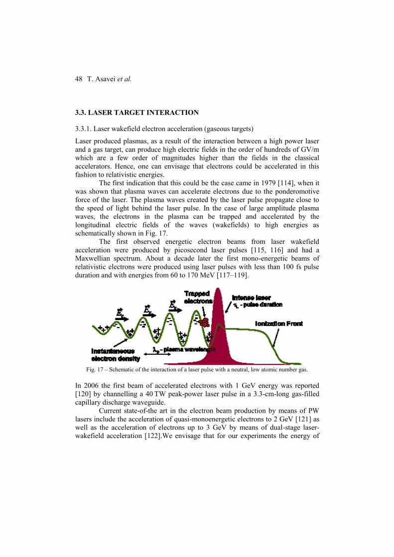
T. Asavei et al.
48
3.3. LASER TARGET INTERACTION
3.3.1. Laser wakefield electron acceleration (gaseous targets)
Laser produced plasmas, as a result of the interaction between a high power laser
and a gas target, can produce high electric fields in the order of hundreds of GV/m
which are a few order of magnitudes higher than the fields in the classical
accelerators. Hence, one can envisage that electrons could be accelerated in this
fashion to relativistic energies.
The first indication that this could be the case came in 1979 [114], when it
was shown that plasma waves can accelerate electrons due to the ponderomotive
force of the laser. The plasma waves created by the laser pulse propagate close to
the speed of light behind the laser pulse. In the case of large amplitude plasma
waves, the electrons in the plasma can be trapped and accelerated by the
longitudinal electric fields of the waves (wakefields) to high energies as
schematically shown in Fig. 17.
The first observed energetic electron beams from laser wakefield
acceleration were produced by picosecond laser pulses [115, 116] and had a
Maxwellian spectrum. About a decade later the first mono-energetic beams of
relativistic electrons were produced using laser pulses with less than 100 fs pulse
duration and with energies from 60 to 170 MeV [117–119].
Fig. 17 – Schematic of the interaction of a laser pulse with a neutral, low atomic number gas.
In 2006 the first beam of accelerated electrons with 1 GeV energy was reported
[120] by channelling a 40 TW peak-power laser pulse in a 3.3-cm-long gas-filled
capillary discharge waveguide.
Current state-of-the art in the electron beam production by means of PW
lasers include the acceleration of quasi-monoenergetic electrons to 2 GeV [121] as
well as the acceleration of electrons up to 3 GeV by means of dual-stage laser-
wakefield acceleration [122].We envisage that for our experiments the energy of
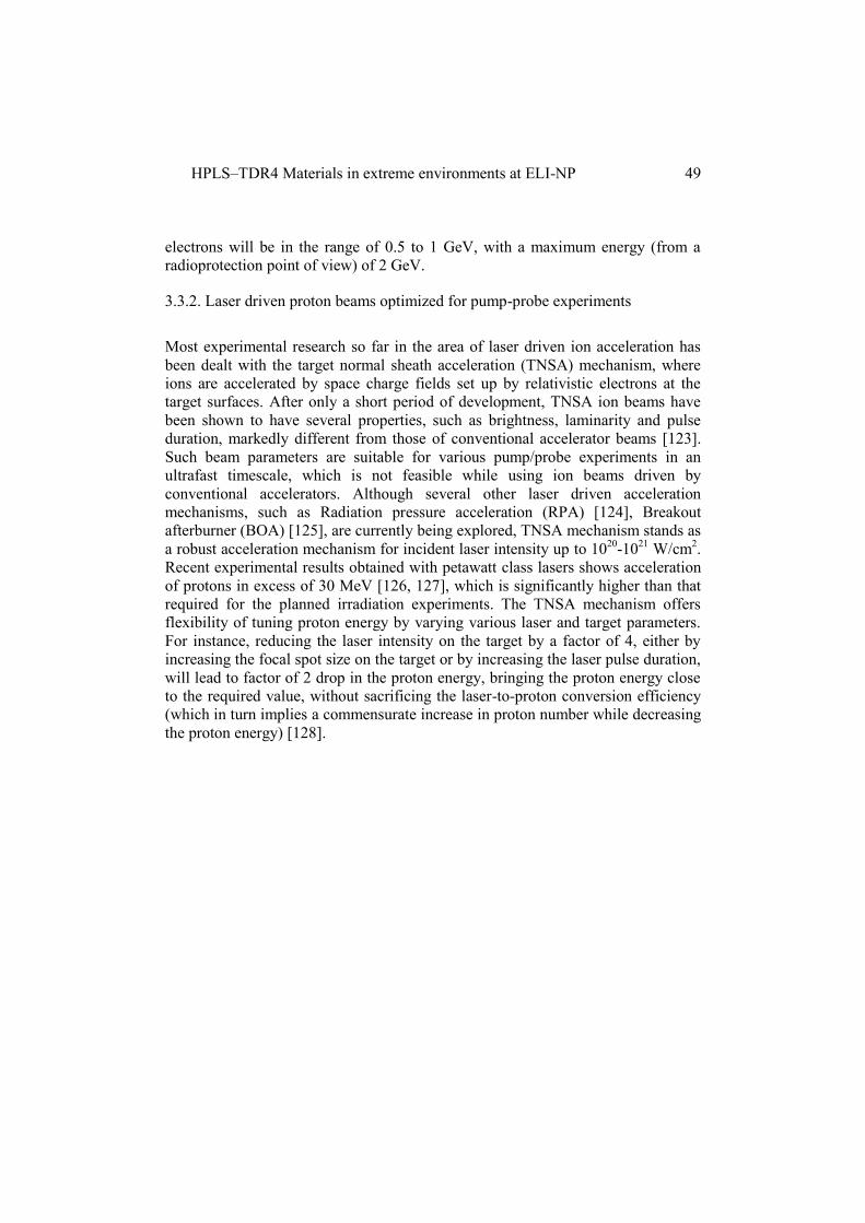
HPLS–TDR4 Materials in extreme environments at ELI-NP
49
electrons will be in the range of 0.5 to 1 GeV, with a maximum energy (from a
radioprotection point of view) of 2 GeV.
3.3.2. Laser driven proton beams optimized for pump-probe experiments
Most experimental research so far in the area of laser driven ion acceleration has
been dealt with the target normal sheath acceleration (TNSA) mechanism, where
ions are accelerated by space charge fields set up by relativistic electrons at the
target surfaces. After only a short period of development, TNSA ion beams have
been shown to have several properties, such as brightness, laminarity and pulse
duration, markedly different from those of conventional accelerator beams [123].
Such beam parameters are suitable for various pump/probe experiments in an
ultrafast timescale, which is not feasible while using ion beams driven by
conventional accelerators. Although several other laser driven acceleration
mechanisms, such as Radiation pressure acceleration (RPA) [124], Breakout
afterburner (BOA) [125], are currently being explored, TNSA mechanism stands as
a robust acceleration mechanism for incident laser intensity up to 1020
-1021
W/cm2.
Recent experimental results obtained with petawatt class lasers shows acceleration
of protons in excess of 30 MeV [126, 127], which is significantly higher than that
required for the planned irradiation experiments. The TNSA mechanism offers
flexibility of tuning proton energy by varying various laser and target parameters.
For instance, reducing the laser intensity on the target by a factor of 4, either by
increasing the focal spot size on the target or by increasing the laser pulse duration,
will lead to factor of 2 drop in the proton energy, bringing the proton energy close
to the required value, without sacrificing the laser-to-proton conversion efficiency
(which in turn implies a commensurate increase in proton number while decreasing
the proton energy) [128].

T. Asavei et al.
50
Fig. 18 – Graphs (a) and (b) show the recent experimental data on maximum proton energy produced
from the interaction of petawatt class laser with thin foils. (c) and (d) show previously reported
scaling for proton energy and conversion efficiency with respect to laser intensity and energy
(reproduced with permission from [126, 127]).
TNSA driven proton beam is an extremely suitable candidate for probing highly
transient phenomena with ps temporal and micron spatial resolutions. Where the
micrometre scale source size of the protons (due to the micrometre scale focal spot
size of the intense laser on the target) allows 2D radiograph of an object to be taken
in a point-projection imaging scheme, broad energy spectrum of the source provide
multi-frame probing capability due to different time of flights of different energy
protons arriving at the probed object [129]. Proton radiography is a well-
established diagnostics used in the laser plasma interaction experiments to study
underlying physical mechanisms by mapping, spatially and temporally, the
evolution of transient electric and magnetic fields associated with the interaction.
Proton radiography is also suitable for studying small density variation across a
probed object due to small-angle scattering of protons sensitive to material type
and density [130]. With the dual pulse capability of the E5 experimental area, the
(a)
(b)
(c) (d)
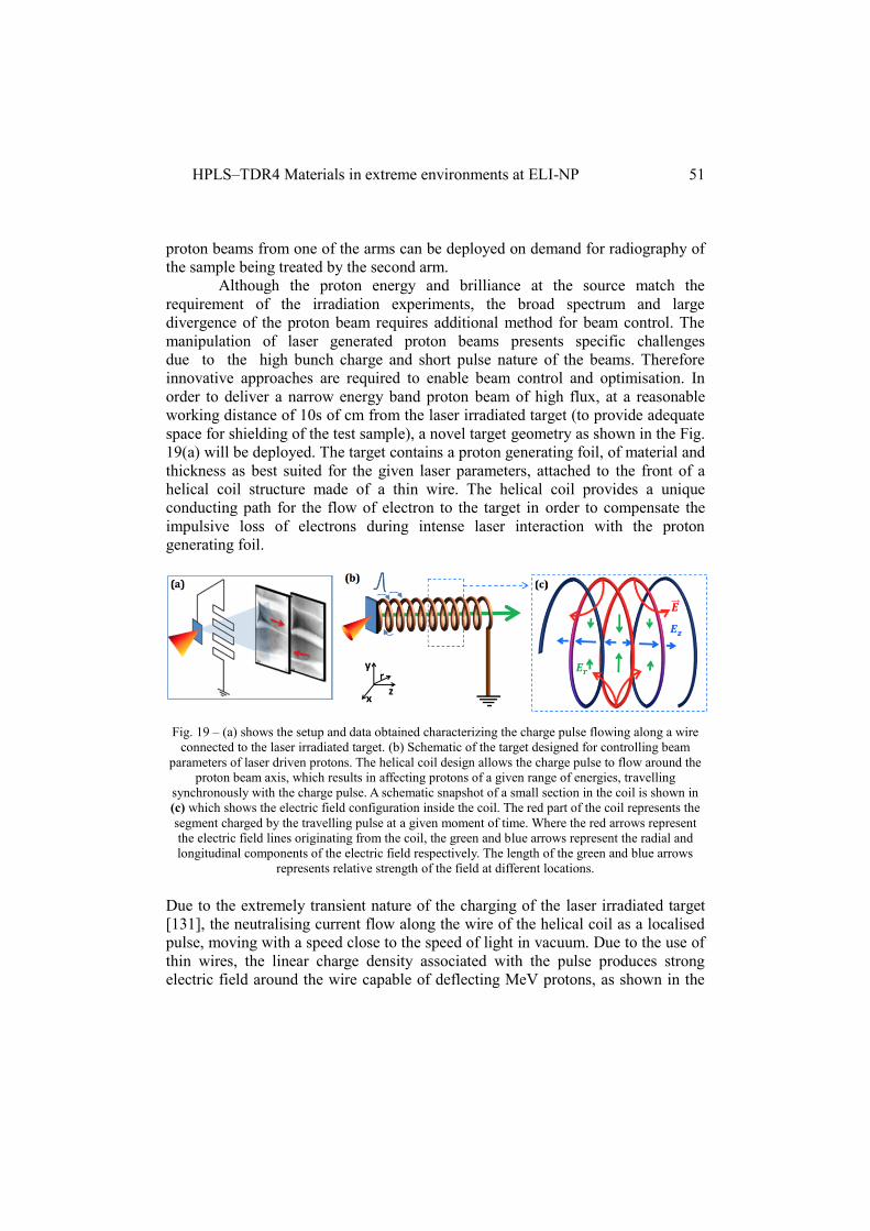
HPLS–TDR4 Materials in extreme environments at ELI-NP
51
proton beams from one of the arms can be deployed on demand for radiography of
the sample being treated by the second arm.
Although the proton energy and brilliance at the source match the
requirement of the irradiation experiments, the broad spectrum and large
divergence of the proton beam requires additional method for beam control. The
manipulation of laser generated proton beams presents specific challenges
due to the high bunch charge and short pulse nature of the beams. Therefore
innovative approaches are required to enable beam control and optimisation. In
order to deliver a narrow energy band proton beam of high flux, at a reasonable
working distance of 10s of cm from the laser irradiated target (to provide adequate
space for shielding of the test sample), a novel target geometry as shown in the Fig.
19(a) will be deployed. The target contains a proton generating foil, of material and
thickness as best suited for the given laser parameters, attached to the front of a
helical coil structure made of a thin wire. The helical coil provides a unique
conducting path for the flow of electron to the target in order to compensate the
impulsive loss of electrons during intense laser interaction with the proton
generating foil.
Fig. 19 – (a) shows the setup and data obtained characterizing the charge pulse flowing along a wire
connected to the laser irradiated target. (b) Schematic of the target designed for controlling beam
parameters of laser driven protons. The helical coil design allows the charge pulse to flow around the
proton beam axis, which results in affecting protons of a given range of energies, travelling
synchronously with the charge pulse. A schematic snapshot of a small section in the coil is shown in
(c) which shows the electric field configuration inside the coil. The red part of the coil represents the
segment charged by the travelling pulse at a given moment of time. Where the red arrows represent
the electric field lines originating from the coil, the green and blue arrows represent the radial and
longitudinal components of the electric field respectively. The length of the green and blue arrows
represents relative strength of the field at different locations.
Due to the extremely transient nature of the charging of the laser irradiated target
[131], the neutralising current flow along the wire of the helical coil as a localised
pulse, moving with a speed close to the speed of light in vacuum. Due to the use of
thin wires, the linear charge density associated with the pulse produces strong
electric field around the wire capable of deflecting MeV protons, as shown in the

T. Asavei et al.
52
(e)
proton radiographs of the charged wires taken by MeV protons (see Fig. 19a). The
helical target geometry aims to employ this field for simultaneous focussing,
energy selection and post-acceleration of MeV protons, by allowing the charge
pulse to travel in a helical path around the proton beam axis, as shown by the
schematic in Fig.19b. The effective longitudinal velocity of the associated electric
field pulse is determined by the coil geometry, and, with an appropriate choice of
parameters (e.g. coil diameter and pitch), the field can co-move with a desired
section of the TNSA proton spectrum, over an extended propagation length. In this
configuration, the radial and longitudinal components of the electric field act,
respectively, towards focussing and further acceleration of the co-moving protons
(or deceleration for the protons lagging behind the charge pulse).
For an illustration, Fig. 20 shows a typical data obtained at the in-house
TARANIS laser (10 TW CPA laser delivering intensity of a few times 1019
W/cm2
on target) facility at the Queen’s University Belfast (QUB). The foil-coil target in
this case has produced a highly collimated/focussed beam of protons, with a
commensurate (nearly an order of magnitude) enhancement of proton flux, in
comparison to the typical divergent proton beam produced by a normal flat foil. By
varying the radius and pitch of the coil, the flow of the charge pulse was
synchronized with different ranges of proton energies, resulting in focused beams
of different energies. The unsynchronized protons in this case maintain their
intrinsic divergence, which will allow spectral tailoring by using a spatial aperture
at a far distance from the target.
Fig. 20 – (a) and (c) shows the schematic of the experimental setups for the reference flat foil and the
proposed coil target respectively. (b) and (d) shows the proton beam profile obtained over different
layers of detectors (corresponding to different beam energy) for the case (a) and (c) respectively. (e)
shows the comparison between the horizontal lineouts across the proton beams obtained in the 4th
layer of (b) and (d).
The peak charge density/current in the wire depends on hot electron temperature
and flux, which in turn depends on the intensity and energy of the incident laser
pulse. Therefore one can expect a significant increase in electric field strength

HPLS–TDR4 Materials in extreme environments at ELI-NP
53
inside the helical coil while using this technique at the E5 target area equipped with
Petawatt laser.
Experimental Plan:
The helical coil targetry is made of thin metal wires (approximately 100 µm
diameter) winded into the shape of a helix, where the diameter and pitch is chosen
as per the required beam output. For example, a helical coil of mm-sized diameter,
few hundreds of µm pitch and a few cm long is suitable for generating a pencil
beam 10-20 MeV protons, which is the desired energy range for most of the
planned experiments in the E4 and E5 target areas. Being connected directly to the
rear of the proton generating target, the “foil+coil” assembly stands up as a single
target which provides greater flexibility in terms of target deployment and
alignment. A number of “foil+coil” targets can be mounted on a
translational/rotational stage for shooting at a fast repetition, without the need for
breaking the vacuum of the interaction chamber. The coil targets will be mass-
manufactured with high precision and reproducibility, and will be provided by
QUB.
Since TNSA acceleration is not prone to low contrast of laser, as long as a
suitable thickness of the proton generating foil is chosen (typically a few µm up to
10 µm, depending on the laser), one could benefit in terms of proton energy and
flux by bypassing the lossy plasma mirror system. Due to the compactness of the
target, the multi-target stage can be easily fielded inside the interaction chambers at
E5 target area. The targets can be aligned in the same way as one would do so for
simple flat foil targets. The output beam from the coil targets is highly collimated
(less than 0.5 degrees divergence), which mitigates the technical and radiation
issues associated with setting a secondary target in a close proximity to the primary
proton generating target. The pointing of the proton beam exiting the coil target
solely depends on the axis of the coil, which can be controlled with micron
precision. Therefore, one could simply use an appropriate shielding in between the
primary and secondary targets, with a sub-mm pinhole aperture for the proton
beam to pass through. Due to extremely low divergence of the proton beam, the
secondary target can be placed several tens of cm from the coil target, which will
provide enough room for using a thick shielding of high Z material in order to
reduce significantly the exposure of other intense radiations, such as X-rays,
produced by the laser plasma interaction. In order to assure a cleaner irradiation
environment, one can also use a setup as shown in the Fig. 21. In this case, a pair of
strong magnets (approximately 1T) can be used to steer the pencil beam of protons
exiting the coil target by a small angle as adequate for blocking the direct line of
sight between the sample and the laser interaction point. The proton flux on the

T. Asavei et al.
54
sample will not be compromised in this case because of the low divergence and
energy bandwidth of the beam produced by the coil targets.
Fig. 21 – A schematic (not to scale) of the experimental setup using magnets to steer the pencil beam
of narrow energy bandwidth protons coming out of the coil target. In this case the shielding can be
placed obliquely in order to obscure the direct line of sight from the laser interaction. This setup will
therefore allow an extremely clean irradiation environment. Tentative dimensions and separation
between different objects are mentioned.
3.3.3. Neutron production from secondary protons
Over the past decade, significant attention has been paid to laser driven sources
capable of producing short neutron bursts due to the advantages in terms of cost
reduction and compactness, reduction of radioactive pollution and ability of
radiation confinement by closely-coupled experiments. Among the possible laser
energised nuclear phenomena, the most established route to create a neutron source
is employing laser accelerated ions in either fusion or spallation reactions. Since
spallation reactions require high energy projectile ions, fusion reactions based on
low atomic mass nuclei, such as 7Li(p,n)
7Be,
9Be(p,n)
9B,
13C(p,n)
13N, d(d,n)
3He,
T(d,n)4He,
7Li(d,xn),
7Be(d,xn), are particularly relevant. The neutron yield from
fusion reactions scales with the product of fusing ion densities and cross-section σ,
which for most common reactions reaches high values for centre-of-mass energy in
MeV range (see Fig. 23). Such a source is expected to provide not only a short
initial pulse width (in sub-nanosecond range), but also a narrow band energy
spectrum so that the pulse duration is maintained over a reasonable distance from
the source.

HPLS–TDR4 Materials in extreme environments at ELI-NP
55
(a) (b)
Fig. 22 – Comparison between cross-sections of a few fusionreactions. D-D reaction have high yield
for sub-MeV ions, D-low Z reaction have significantly high yield for higher ion energies.
Fig. 23 – (a) In-target Fusion: Experimentally obtained neutron yields [133, 134, 135, 136, 137, 138,
139, 140, 141, 142, 143, 144, 145] (red circles) collected from literature for vs. estimated (black)
neutron yield at different laser intensities is shown. Increase in deuterium ion energy from the front
surface of a solid deuterated plastic foil, driven by hole-boring mechanism, with increase in laser
intensity is shown as blue solid line. (b) Pitcher-catcher setup: Experimentally obtained on-axis
neutron flux collected from literature as a function of laser intensity. Red, black and blue dots shows
the data obtained for TNSA driven proton and deuterium ions on Li Catcher [145, 146, 147, 148,
149], TNSA driven deuterium ions on deuterium catcher [150] and BOA driven deuterium ions on Cu
and Be catcher [151].
Producing high flux of MeV ions using intense lasers is currently an area of intense
research [123]. Where a number of emerging ion acceleration mechanisms, such as
Radiation Pressure acceleration (RPA) [124] and Breakout afterburner (BOA)
[125], hold the promise for producing higher energy ions with higher efficiency,
Target Normal Sheath acceleration (TNSA) is a well-established and robust
mechanism which produces MeV ions with high flux and narrow divergence. Such
beams can be readily deployed in a pitcher-catcher setting for neutron generation
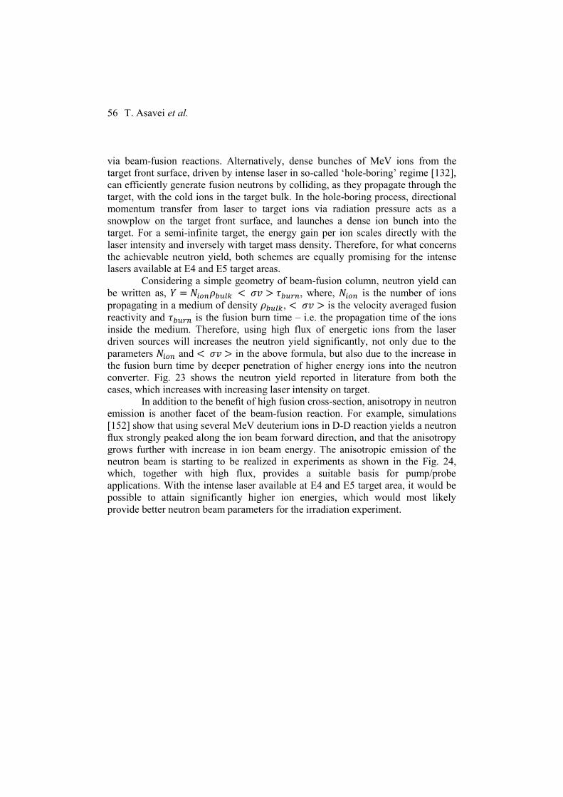
T. Asavei et al.
56
via beam-fusion reactions. Alternatively, dense bunches of MeV ions from the
target front surface, driven by intense laser in so-called ‘hole-boring’ regime [132],
can efficiently generate fusion neutrons by colliding, as they propagate through the
target, with the cold ions in the target bulk. In the hole-boring process, directional
momentum transfer from laser to target ions via radiation pressure acts as a
snowplow on the target front surface, and launches a dense ion bunch into the
target. For a semi-infinite target, the energy gain per ion scales directly with the
laser intensity and inversely with target mass density. Therefore, for what concerns
the achievable neutron yield, both schemes are equally promising for the intense
lasers available at E4 and E5 target areas.
Considering a simple geometry of beam-fusion column, neutron yield can
be written as, 𝑌 = 𝑁𝑖𝑜𝑛𝜌𝑏𝑢𝑙𝑘 < 𝜎𝑣 > 𝜏𝑏𝑢𝑟𝑛, where, 𝑁𝑖𝑜𝑛 is the number of ions
propagating in a medium of density 𝜌𝑏𝑢𝑙𝑘, < 𝜎𝑣 > is the velocity averaged fusion
reactivity and 𝜏𝑏𝑢𝑟𝑛 is the fusion burn time – i.e. the propagation time of the ions
inside the medium. Therefore, using high flux of energetic ions from the laser
driven sources will increases the neutron yield significantly, not only due to the
parameters 𝑁𝑖𝑜𝑛 and < 𝜎𝑣 > in the above formula, but also due to the increase in
the fusion burn time by deeper penetration of higher energy ions into the neutron
converter. Fig. 23 shows the neutron yield reported in literature from both the
cases, which increases with increasing laser intensity on target.
In addition to the benefit of high fusion cross-section, anisotropy in neutron
emission is another facet of the beam-fusion reaction. For example, simulations
[152] show that using several MeV deuterium ions in D-D reaction yields a neutron
flux strongly peaked along the ion beam forward direction, and that the anisotropy
grows further with increase in ion beam energy. The anisotropic emission of the
neutron beam is starting to be realized in experiments as shown in the Fig. 24,
which, together with high flux, provides a suitable basis for pump/probe
applications. With the intense laser available at E4 and E5 target area, it would be
possible to attain significantly higher ion energies, which would most likely
provide better neutron beam parameters for the irradiation experiment.
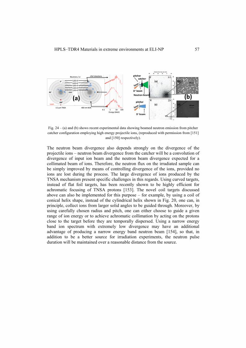
HPLS–TDR4 Materials in extreme environments at ELI-NP
57
(a) (b)
Fig. 24 – (a) and (b) shows recent experimental data showing beamed neutron emission from pitcher
catcher configuration employing high energy projectile ions, (reproduced with permission from [151]
and [150] respectively).
The neutron beam divergence also depends strongly on the divergence of the
projectile ions – neutron beam divergence from the catcher will be a convolution of
divergence of input ion beam and the neutron beam divergence expected for a
collimated beam of ions. Therefore, the neutron flux on the irradiated sample can
be simply improved by means of controlling divergence of the ions, provided no
ions are lost during the process. The large divergence of ions produced by the
TNSA mechanism present specific challenges in this regards. Using curved targets,
instead of flat foil targets, has been recently shown to be highly efficient for
achromatic focusing of TNSA protons [153]. The novel coil targets discussed
above can also be implemented for this purpose – for example, by using a coil of
conical helix shape, instead of the cylindrical helix shown in Fig. 20, one can, in
principle, collect ions from larger solid angles to be guided through. Moreover, by
using carefully chosen radius and pitch, one can either choose to guide a given
range of ion energy or to achieve achromatic collimation by acting on the protons
close to the target before they are temporally dispersed. Using a narrow energy
band ion spectrum with extremely low divergence may have an additional
advantage of producing a narrow energy band neutron beam [154], so that, in
addition to be a better source for irradiation experiments, the neutron pulse
duration will be maintained over a reasonable distance from the source.

T. Asavei et al.
58
3.3.4. Gamma and X-ray generation from laser-target interaction
A. Betatron radiation
Similarly to classical synchrotrons, X-rays can be generated by high-power lasers
interacting with gas jets. This application of high intensity laser has been
demonstrated [155] by focusing the laser onto a gas jet and hence the accelerated
electrons underwent betatron oscillations. The outcome was the generation of
femtosecond pulsed synchrotron radiation with up to 10 keV energy. Also, the
radiation was highly collimated, with a 50 mrad cone angle.
It has also been shown [156] that gamma rays can also be produced by
enhancing the betatron amplitude when the electrons interact with the rear of the
laser pulse. Thus, for 700 MeV accelerated electrons, gamma rays with spectra
peaking between 20 and 150 keV were observed as well as high energy photons
between 1 and 7 MeV.
B. X-rays generated by laser-solid target interaction
When a high power laser is focused onto a solid target, a high-temperature plasma
is formed. Subsequently an ultrafast X-ray pulse is emitted when the incident laser
pulse has femtosecond duration [157]. In this way, Kα sources can be obtained
with energies as a function of the irradiated material (Al at 1.5 keV; Ca at 3.7 keV;
Fe at 6.4 keV) [158]. This type of radiation is particularly suited to laser-based X-
ray diagnostic. Recently [69] it has been shown that femtosecond lived laser pulses
can be trapped in an array of metallic nanowires and X-ray M-shell spectra were
observed.
C. All-optical Compton gamma-ray source
Another interesting way of producing gamma-rays by means of femtosecond laser
pulses is the method based on the Compton scattering of photons by the relativistic
electrons produced by laser plasma acceleration. In this way [159] gamma rays
with hundreds of keV.
We envisage that in the experimental room E5, we will be able to generate X-rays
by means of at least two of the above methods (A and B) for X-ray diagnostics as
well as direct X-ray material irradiation.

HPLS–TDR4 Materials in extreme environments at ELI-NP
59
3.4. DIAGNOSTICS
3.4.1. Electron spectrometer
For the characterization of the electron beam obtained in the gas jet, the main tool
will be a dipole magnet spectrometer as shown in the figure below.
Fig. 25 – Schematic description of a 1.2 T magnetic spectrometer with an energy range 0.03-1.1 GeV
(reproduced with permission from [160]).
In our configuration the electron spectrometer will be placed outside the interaction
chamber as depicted in the Fig. 26.

T. Asavei et al.
60
Fig. 26 – 3D CAD design of the interaction chamber and electron spectrometer in the long focal
length (F/20) configuration.
3.4.2. Thomson Parabola
The “positive-ray” parabola, nowadays called the Thomson parabola, was
constructed in 1913 by J.J. Thomson in Cambridge by means of which, he
discovered two isotopes of neon. The operation principle of the Thomson parabola
is as follows: charged particles entering a pinhole, pass through parallel electric
and magnetic fields, and hence are deflected according to their charge to mass
ratio.
A scheme of such a device used in the diagnostics of laser accelerated
charged particles is shown in the figure below [161].
Fig. 27 – Schematic of a Thomson parabola (reproduced with permission from [161]).

HPLS–TDR4 Materials in extreme environments at ELI-NP
61
In our configuration the Thomson parabola will be placed inside the interaction
chamber as depicted in the figure below.
Fig. 28 – 3D CAD design of the interaction chamber in the short focal length configuration and the
Thomson parabola for proton/ion diagnostic.
3.4.3. Synchronized few-cycle probe pulse set-up
If the acceleration dynamics is to be investigated experimentally, diagnostics are
required which can resolve the temporal and spatial scales inherent to the
acceleration process. In recent experiments, its potential to give an insight into,
e.g., laser-wakefield acceleration of electrons could be shown. With this technique,
the laser-generated plasma wave could be visualized with unprecedented detail (see
Fig. 29). Having such a diagnostic tool available will significantly enhance the
experimental possibilities of this laser-facility.

T. Asavei et al.
62
Fig. 29 – Image of a laser-driven plasma wave obtained with a few-cycle probe pulse, (reproduced
with permission from [162]).
This implementation should be planned from the beginning, since space and access
constraints might reduce the possibilities with this diagnostic when implemented at
a later stage. To provide such a synchronized, few-cycle probe pulse for
experiments, a fraction of the compressed main beam needs to be split off, sent
e.g., into a noble-gas filled hollow core fiber for spectral broadening and then
compressed e.g., by reflections off of chirped mirrors. As a result, this probe pulse
can easily be shorter by a factor of 5-6 when compared to the main pulse. This
allows for sub-main pulse probing of laser-plasma interactions. When used in a
transverse probing configuration, the laser-generated plasma is backlighted from
the side and then imaged onto a CCD camera with a high-resolution
Certain detailed aspects should be taken into account when planning the setup for
this probe-pulse facility.
1. The laser energy available in the probe pulse should be high enough to provide
an intense backlighter for the plasma, i.e. that the probe pulse can outshine
self-emission from the plasma or scattering from the main laser pulse. When
using a hollow-core fiber, the energy throughput is limited to around 1 mJ for
an input pulse of 30 fs. Here, the intensity and power need to lie in between the
thresholds necessary to trigger the non-linear frequency conversion (which in
principle works better for higher intensities in the gas) and the threshold for
plasma formation (which sets an upper limit to the intensity).
2. The possibility to vary the probe beam spectrum (especially when the duration
of the probe pulse is not most important) should be taken into account. For
some applications, a probe frequency which is well-separated from a multiple
of the fundamental laser frequency might be useful. Here, spectral broadening
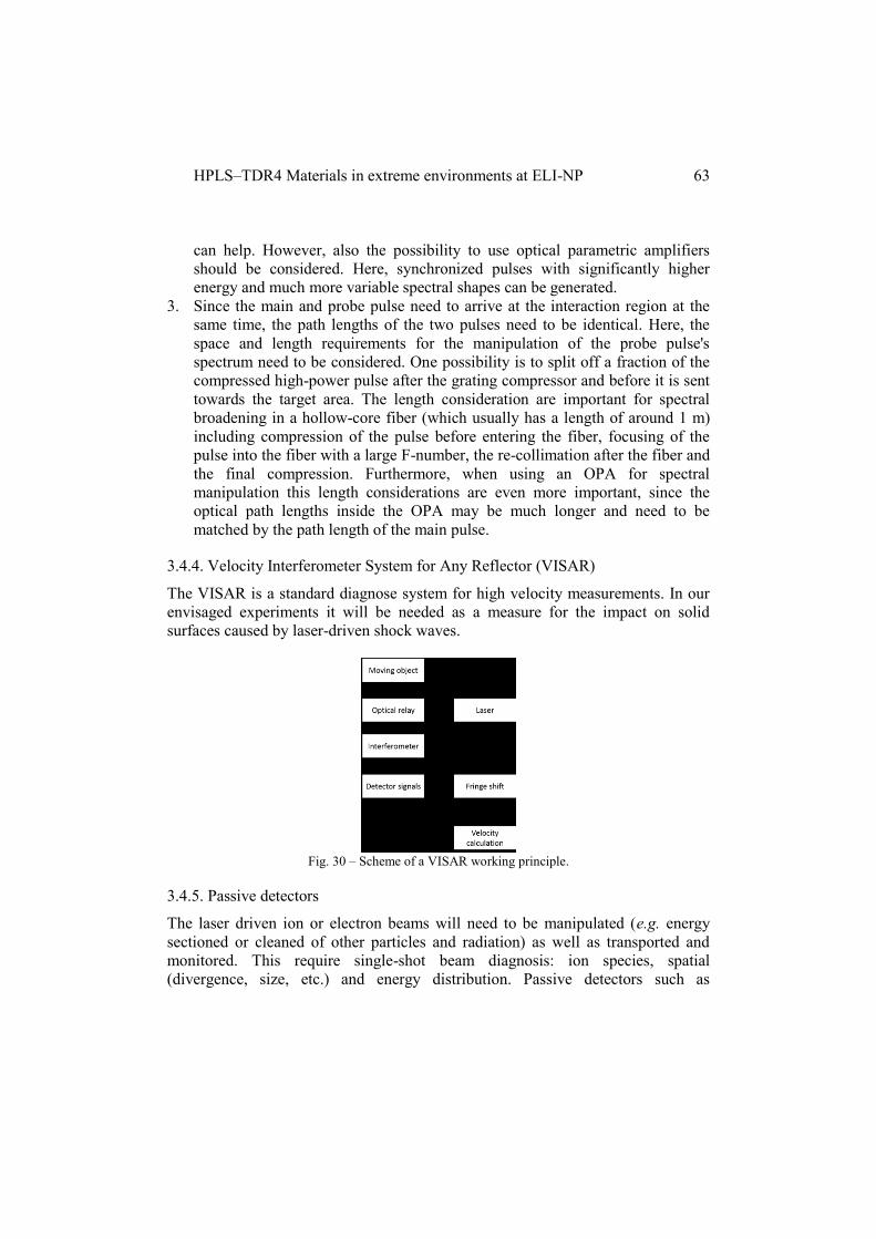
HPLS–TDR4 Materials in extreme environments at ELI-NP
63
can help. However, also the possibility to use optical parametric amplifiers
should be considered. Here, synchronized pulses with significantly higher
energy and much more variable spectral shapes can be generated.
3. Since the main and probe pulse need to arrive at the interaction region at the
same time, the path lengths of the two pulses need to be identical. Here, the
space and length requirements for the manipulation of the probe pulse's
spectrum need to be considered. One possibility is to split off a fraction of the
compressed high-power pulse after the grating compressor and before it is sent
towards the target area. The length consideration are important for spectral
broadening in a hollow-core fiber (which usually has a length of around 1 m)
including compression of the pulse before entering the fiber, focusing of the
pulse into the fiber with a large F-number, the re-collimation after the fiber and
the final compression. Furthermore, when using an OPA for spectral
manipulation this length considerations are even more important, since the
optical path lengths inside the OPA may be much longer and need to be
matched by the path length of the main pulse.
3.4.4. Velocity Interferometer System for Any Reflector (VISAR)
The VISAR is a standard diagnose system for high velocity measurements. In our
envisaged experiments it will be needed as a measure for the impact on solid
surfaces caused by laser-driven shock waves.
Fig. 30 – Scheme of a VISAR working principle.
3.4.5. Passive detectors
The laser driven ion or electron beams will need to be manipulated (e.g. energy
sectioned or cleaned of other particles and radiation) as well as transported and
monitored. This require single-shot beam diagnosis: ion species, spatial
(divergence, size, etc.) and energy distribution. Passive detectors such as

T. Asavei et al.
64
Gafchromic films, image plates, CR39 track detectors are routinely used in high
intensity laser mater interaction [163, 164]. While not fully suited for extensive use
at the high repetition rate of the ELI-NP lasers, they are necessary in certain
experiments and for calibration and validation of online detectors as they have
broader spectral sensitivity, excellent resolution and specificity.
A Radiochromic (Gafchromic) Films
Radiochromic films, which changes its optical density when irradiated by
ionization radiation (electrons, X-ray, ions, etc) are going to be used primarily in
the diagnosis of the laser accelerated beam. The optical density of RCF’s depend
linearly to the dose delivered up to high values (1000 Gy), thus being suited for
high fluxes of radiation. Radiochromic films (RCF), placed in a stack configuration
and optionally sandwiched between copper or aluminium absorbing layer, are
going to be used to obtain 3D image of the spatial and energy distribution of the
laser accelerated ions (radio-chromic imaging spectroscopy [165]. They will be
also used in conjunction with Thomson parabola or ion wide angle spectrometers to
obtain the ion species composition. The mean range in these films is around 25
MeV/u). As a passive, plastic detector, is immune to electromagnetic pulse thus
can be placed close (few centimeters) behind the target. RCF films batches need to
be calibrated with a known ion beam flux and are post-processed at latest 24h after
exposure. For post processing a CCD based document scanner can be used.
B CR39
CR39 are plastic polymer track detector that can be used in a stack configuration
for beam profiling as well as detector for Thomson parabolas or ion wide angle
spectral detector. The advantage of using them is insensitivity to photons, electrons
or above 10 MeV protons. Thus they are especially required when different species
of ions must be characterized [125].
C. Image Plates (IP)
Image plates are 2D imagining sensors used in conjunction with Thomson
parabola’s and ion/electron spectrometers. Similar to RCF, image plates are
sensitive to broader range of radiation kinds, have great dynamic range and
sensitivity making them suited for the high radiation fluxes present in high power
laser experiments [166]. The IP films contains layers of phosphorus elements that
are driven in metastable excited states when excited by radiation and post-
processed through optically stimulated luminescence by a laser scanner. The spatial
resolution is in the range of 25-50 mm. One advantage of IPs is that they are
reusable.
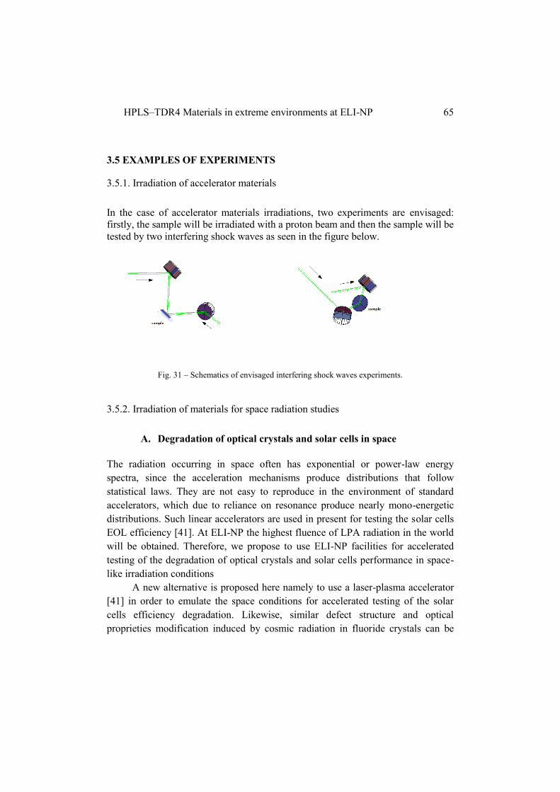
HPLS–TDR4 Materials in extreme environments at ELI-NP
65
3.5 EXAMPLES OF EXPERIMENTS
3.5.1. Irradiation of accelerator materials
In the case of accelerator materials irradiations, two experiments are envisaged:
firstly, the sample will be irradiated with a proton beam and then the sample will be
tested by two interfering shock waves as seen in the figure below.
Fig. 31 – Schematics of envisaged interfering shock waves experiments.
3.5.2. Irradiation of materials for space radiation studies
A. Degradation of optical crystals and solar cells in space
The radiation occurring in space often has exponential or power-law energy
spectra, since the acceleration mechanisms produce distributions that follow
statistical laws. They are not easy to reproduce in the environment of standard
accelerators, which due to reliance on resonance produce nearly mono-energetic
distributions. Such linear accelerators are used in present for testing the solar cells
EOL efficiency [41]. At ELI-NP the highest fluence of LPA radiation in the world
will be obtained. Therefore, we propose to use ELI-NP facilities for accelerated
testing of the degradation of optical crystals and solar cells performance in space-
like irradiation conditions
A new alternative is proposed here namely to use a laser-plasma accelerator
[41] in order to emulate the space conditions for accelerated testing of the solar
cells efficiency degradation. Likewise, similar defect structure and optical
proprieties modification induced by cosmic radiation in fluoride crystals can be

T. Asavei et al.
66
studied in such a configuration. The effects of irradiation on the luminescence
efficiency as well on the other spectral and thermal properties of the fluorides will
be investigated.
Tasks:
– To measure the solar cell parameters at BOL (beginning of life).
– To study the structural defects-dislocations in (Ba/Ca)F2 crystals before
irradiation.
– Absorption/transmission IR-VIS-UV spectroscopy of (Ba/Ca)F2 crystals
before irradiation.
– To expose the solar cells and grown fluoride crystals to an electrons and
protons flux generated by LPA – ELI.
– To measure the solar cell parameters at EOL (end of life).
– To study the structural defects-dislocations in (Ba/Ca)F2 crystals after
irradiation.
– Absorption/transmission IR-VIS-UV spectroscopy of (Ba/Ca)F2 crystals
after irradiation.
All electrical parameters of the solar cell should be carried out under AM0
condition.
B. Doped fluoride crystals irradiation for fundamental studies of
optical properties modification
The irradiated induced defect structure depends on the energy of the particle
radiation. The possibility to obtain a heterogeneous energy spectra of the electron
and proton beams though LPA in a single laser shot is useful for making a fast,
cost-effective and simultaneous exposure of different segments of a crystalline
probe (or of various probes) at different energies in different positions by using a
deflecting magnetic field, as proposed in [41]. A very important aspect of LPA use
for radiation induced optical defects in crystals also concerns the availability of an
easily tunable and cheap proton source, compared to the high costs involved with
classical proton accelerators. Also, charge conversions from Yb3+
to Yb2+
could be
rapidly reached with the high dose per pulse of the LPA radiation obtained at ELI-
NP, for the improvement of the UV emission intensity of Yb2+
, which can be used
in lasers for psoriasis treatment.

HPLS–TDR4 Materials in extreme environments at ELI-NP
67
Tasks:
– Growth of various rare earth concentrations doped (Ba/Ca)F2 crystals at WUT.
– Absorption/transmission IR-VIS-UV spectroscopy of various concentrations
rare earth doped (Ba/Ca)F2 crystals before and after irradiation.
– Dielectric spectra of various concentrations rare earth doped (Ba/Ca)F2
crystals before and after irradiation.
3.5.3 Technical proposal for irradiation of biological systems
Various technical aspects regarding the irradiation of biological samples are
detailed below.
A. Irradiation platforms for preclinical studies
As a preparation of a logistic support for irradiation of bio-materials studies at ELI-
NP, the facility will provide a Bio-Lab Unit for cell culture and animal tissue
handling, sample conservation and measurements necessary immediately after
irradiation. This unit will also offer support and preparation of experiments prior to
moving the samples in the irradiation area. The Bio-Lab Unit should provide
adequate conditions for long-term cell cultures, i.e. 37oC, controlled CO2 and O2
environment, and humidity, temporary handling of small animals (mice) and tissue
harvesting. It is not envisioned any experimental development using pathogenic
agents (viruses, bacteria, fungi) at ELI-NP.
After the primary processing of samples (normal/diseased cells or animal
tissue) at ELI-NP, more processing, test-oriented will follow in the specialized
laboratories at the National Institute of Pathology Victor Babes (INCDVB), located
in Bucharest. Support will be provided also by relevant departments at the National
Institute for Physics and Nuclear Engineering Horia Hulubei (IFIN-HH). For
exposure to radiation of in-vitro and in-vivo samples, adequate small chambers will
be designed and built to adapt 2D cell monolayers, 3D cell volumes or laboratory
animals, depending on specific study requirements. For the in vivo studies on
animal models regarding the new irradiation approach in cancer (2nd
stage of the
study) the irradiation platform will be connected to a performant imagistic
equipment, such as mini CT or PET-CT. This is necessary for precisely locating
the tumor for directing the radiation beam towards tumors, whilst sparing normal
tissues. The irradiation platforms will provide both diffuse radiation, relevant for
T. Asavei et al.
68
mimicking GCR-like effects, and a highly focused radiation beam, relevant for
cellular irradiation and thus attenuators and collimators will be designed and built.
The use of small laboratory animals will only be limited for studies where
significant understanding from in-vitro experiments will first be achieved and will
follow the European and Romanian laws and regulations. All licenses necessary
will be obtained from the appropriate regulatory agency ANSVSA (“Autoritatea
Nationala Sanitar-Veterinara si pentru Siguranta Alimentelor”- National Agency
for Animal Welfare and Food Safety). In addition an ethical committee for welfare
of animals used in experiments similar to those acting in universities and the
affiliated research institutes from other European countries (i.e. UK, France,
Belgium), will be based in the Department of Life and Environmental Sciences at
National Institute of Physics and Nuclear Engineering (IFIN-HH) and will approve
the experimental protocols that will guarantee the welfare of animals during
experiments.
The new development at ELI-NP facility will be from in-vitro
investigations to animal studies, from “rough” effects to molecular mechanisms of
action, from multi-parameter screening using “omics” technologies to validation of
particular biomarkers and mechanisms. Due to the absolute novelty of the ELI-
generated ionizing radiation, such a comprehensive approach is mandatory.
Previous results obtained using less complex irradiation models will only guide this
study. Many physiologic processes should be tackled for generating a realistic
biologic image of the multi-component radiation effects on complex organisms.
B. General Protocols
a. Biological samples
– 2D and 3D cultures of normal, cancer and inflammatory cells
(primary cells and cell lines) will be used.
– Normal and transgenic small laboratory animals (animal models
for various pathological conditions), will be purchased from The
Jackson Laboratory, USA, and will be further maintained in
standardized conditions at the animal care facility of INCDVB and
IFIN-HH.
– Tissues/cells harvested from the irradiated animals, preserved for
various biomedical tests, will be stored until use in the deep
freezing unit of INCDVB, using standardized bio-banking
procedures.
b. Biomedical investigations
– In vitro cellular studies

HPLS–TDR4 Materials in extreme environments at ELI-NP
69
– phenotyping (immunochemistry, confocal microscopy, flow
cytometry), viability tests, taking into account a panel of
cellular death types (confocal microscopy, flow cytometry)
– cell proliferation (flow cytometry, impedance measurements
on adherent cells)
– genotoxicity (micronuclei test on bone marrow cells)
– oxidative stress and the antioxidant response (flow
cytometry, pathway-focused PCR array, signal reporter
assay)
– cellular secretory activity (ELISA, protein multiplexing by
Luminex or protein microarray)
– signal transduction pathways (Western blot, intracellular
protein multiplexing using Luminex)
– genetic instability assessed by karyotyping
– gene expression profile (PCR array, gene microarray)
– epigenomic investigation (total and specific methylation
status, chromatin immuno-precipitation, micro RNA profile)
– In vivo studies in animal models
– in vivo imaging of animals (IFIN-HH)
– (ultra)structural ex vivo investigation of cells/tissues (high
resolution transmission electron microscopy, histological
and immuno-histochemical investigation)
– organ toxicity and signal transduction events (gene
expression by pathway-focused PCR arrays, gene
microarray) and further validation of candidate genes by RT-
PCR
– classical cytogenetic investigation (karyotyping) for
assessing genetic instability
– epigenomic investigation (microRNAs profile in
cells/tissues/serum)
– protein profiling in serum (Luminex, protein microarray,
SELDI-TOF mass spectrometry) and further validation of
protein biomarkers by ELISA/Western blot
– immunologic screening: immuno-phenotype, functional
investigation of the adaptive and innate immune response (T
lymphocytes and macrophages polarization, the cytokine
profile, oxidative stress and the antioxidant response)

T. Asavei et al.
70
A flow chart describing the experimental steps and data management is shown in
Fig. 32.
Fig. 32 – Flowchart of activities for envisaged biological research at ELI-NP.
A specific study is detailed below:

HPLS–TDR4 Materials in extreme environments at ELI-NP
71
Non-targeted effects induced by low dose “mix” of secondary radiation beams
accessible at ELI-NP. Bystander and adaptive responses to space like radiation
exposures.
The project is based on the irradiation capabilities offered by ELI-NP facility: a
complex tunable, multicomponent and multienergetic radiation which will mimic
Cosmic ray stressful conditions. For the near future the most important problem to
address in this domain is the radiation risk estimation for the solar system travels.
The lack of detailed knowledge of the biological effects of energetic heavy
ions especially at low dose and low dose rates (low fluences) constitutes the major
source of uncertainty for risk estimates [167, 74]. The exposure risks for astronauts
to solar system irradiation has 2 components [168, 169]:
- Acute risks can be associated to solar energetic particle events (SEP) (up to
900 mSv).
- Late stochastic risks associated to the chronic exposure to galactic cosmic
rays (GCR) providing doses up to 100-fold Earth’s background
(approximately 100-300 mSv/year).
The predominance of protons for each of the sources of space radiation was
demonstrated and dose measurements have been performed during space missions.
The conditions estimated to be offered by ELI-NP for proton irradiation mimics the
lowest part of the galactic radiation component in terms of particle energy (around
20 MeV) and the solar flare radiation in terms of fluency (more than
1010
particles/pulse).
The radiobiology literature outlines some specific research issues
separately for acute effects or for late stochastic effects [170, 171, 35].
Main research issues for acute effects: (i) how is the RBE of protons or heavier
ions modified at low dose rate (low fluency); (ii) how is the radiosensitivity of
individuals modified by the space environment, i.e. microgravity conditions or
hipergravity; (iii) what are the most effective biomedical countermeasures for acute
effects as long as the present radioprotective drugs are toxic and the antioxidants
not effective.
Main research issues for late stochastic effects point to cancer risk, central
nervous system (CNS) risk or to cardiovascular risk. Damage at low fluencies
induced by heavy ions may be both quantitatively and qualitatively different from
low dose low LET exposures. In vitro acceleration studies are needed at DNA,
chromosomal, tissue and gene expression level to assess the relevance of the
different types of damage and different potential processing. Furthermore, multiple
stressors in the cosmic environment can lead to synergistic or antagonistic effects.
T. Asavei et al.
72
Regarding the CNS risk, accelerator experiments using innovative model systems
are needed, e.g. human tissues. It is also important to conclude if there is or not a
threshold for late non-cancer irradiation effects.
It is important to keep in mind that exposures in CR environment occur at
low fluencies and fluency rates, meaning that particle traversals through cells in the
body are well separated as tissue location and time. Non-targeted effects as
bystander response may have increased significance [172]. Our research proposal
intend to address some of the problems not-understood yet in the low dose
radiobiology domain which concern also space radiation exposures - like
bystander responses, hyper radiation sensitivity, adaptive or synergic response to
repetitive low dose exposure or to alternation of repetitive low dose and acute high
dose of energetic protons or heavy ions. The group will take advantage of our
previous experience in the low dose and bystander effects of irradiation [173–177].
Proposed irradiation protocols:
- Separate irradiations: proton single dose irradiation (dose domain 0-5 Gy);
electron single irradiation (dose domain 0-5 Gy); and reference X ray or
gama irradiation (dose domain 0-5 Gy).
- Repetitive irradiations – sequences of exposures of lower doses (0.1-0.5
Gy), up to total doses of 5 Gy.
- Alternative irradiations in the experiments of bystander and adaptive
responses: low dose irradiations (less than 0.5Gy) followed by repetitive or
single irradiations of doses up to 2-5 Gy.
- The alternative irradiation protocols will combine exposures to different
beam types (protons, electrons, gamma, brilliant X-ray).
- The irradiation regimes will include repetitive low fluence exposures,
single short high fluence exposures or combination of them.
Biological models and end-points:
The experiments will be performed on human and rodent cell lines, especially
fibroblasts and brain cells. Normal human cell lines expressing fluorescent markers
will be preferred, as being the most promising biological systems for preliminary
radiobiology experiments on CR. Genetically engineered cell lines to
constitutionally express fluorescent markers (such as green-fluorescent proteins or
luciferase) will allow to monitor transcriptional activity of specific promoters, thus
providing real time information on the viability and metabolic activity of the cells.
In addition this biological model will allow live visualization (by fluorescent
microscopy) of recruitment of DNA repair proteins to sites of particle hits and the
temporal evolution of such damage tracks. Bioluminescence assays will be applied
to monitor metabolic pathways activated in response to radiation and stress or other

HPLS–TDR4 Materials in extreme environments at ELI-NP
73
end-points expected to be altered in reduced microgravity, such as cytoskeleton
functional status [178]. In parallel, we intend to develop a 3-dimentional tissue
model in order to study mechanisms and importance of bystander responses in the
used regime of irradiation.
The investigated end-points in the experiments about DNA toxicity and
repair, cellular toxicity and genomic instability will be: MN induction (light and
fluorescent microscopy), H2AX expression (using fluorescent image analysis,
other DNA repair pathways (using western blotting, PCR), clonogenic cell survival
(microscopy assays), apoptosis induction and mitochondrial transmembranal
potential (using fluorescent image analysis). The bystander experiments will be
performed predominantly in co-culture arrangements.
Irradiation experiments of biological samples with multi-component,
multi-energetic beams require development of several experimental setups
depending on the specifics goal of the study and the type of bio-sample. Cell
monolayers are usually grown inside a standard 96 well plate (127.7×85.48×14.6
mm3). The plate can be sealed with polyethylene sealing film. The 96 well plates
are made of hard plastic (polystyrene). The advantage of irradiating a large number
of samples simultaneously is the relevant statistics, a requirement in the
experimental studies in-vitro. In addition a 96 well plate is accommodated by most
assay equipment for post processing and measurements.
SRIM-TRIM simulations were used for set-up design and optimization.
For irradiation of the 96 well plate inside the interaction chamber a cassette will be
built to protect the samples from vacuum environment but still allowing the
irradiation through the Al or Ni window. This cassette will be filled with air at
atmospheric pressure and the content will be maintained at 37C.
Geant4 simulations have shown that depending on the thickness of the
window and the material used doses ranging from 0.1 to 1.5 Gy can be applied to
the cell monolayer as seen in Fig. 33. The target insertion system can be used to
manipulate the cassette containing the samples. Suspensions of cell, organoids or
tissue will require variations of the experimental setup to ensure uniform
irradiation.

T. Asavei et al.
74
Fig. 33 – Average dose deposited in a cell monolayer as a function of window thickness (preliminary
results from Geant4 simulations of the irradiation setup).
4. CONCLUSIONS
This paper described the future experiments that will take place in the E5
experimental area of ELI-NP. This particular station within the facility will host
two arms of the high power laser system, namely two 1 PW lasers with a repetition
rate of 1 Hz. This capability will enable researchers to perform various experiments
with high power lasers as well as secondary sources generated by these lasers, in
the fields of materials science as well as biological physics.
ACKNOWLEDGEMENTS
The work was performed within the project The Extreme Light
Infrastructure Nuclear Physics (ELI-NP) – Phase I. The project is co-funded by the
European Union through the European Regional Development Fund.
REFERENCES
[1] H. Geissel et al., Technical Report on the Design, Construction, Commissioning
and Operation of the Super-FRS of FAIR, GSI Report 2005-02, (2005).
HPLS–TDR4 Materials in extreme environments at ELI-NP
75
[2] N. A. Tahir, A. Kozyreva, P. Spiller, D. H. H. Hoffmann, and A. Shutov, Phys.
Rev. E 63, 036407 (2001).
[3] G. Heidenreich, AIP Conf. Proc. 642,122-124 (2002).
[4] H. Geissel, H. Weick, M. Winkler, G. Münzenberg, V. Chichkine, M. Yavor, T.
Aumann, K. H.Behr, M. Böhmer, and A. Brünle, Nucl. Instrum. Methods Phys.
Res. B 204, 71-85 (2003).
[5] R. Bernath, C. G. Brown, J. Aspiotis, M. Fisher, M. Richardson, Proc. SPIE
6219, 62109A (2006).
[6] P.K.F. Grieder, Cosmic Rays at Earth (Elsevier, Amsterdam, 2001).
[7] R. A. Mewaldt, Adv. Space Res. 14, 737-747 (1994).
[8] K. Yoshida, Adv. Space Res. 42, 477–485 (2008).
[9] M Kim, J Wilson, and F Cucinotta, Adv. Space Res. 37, 1741-1748 (2006).
[10] R. Battiston, P. Blasi, M.T. Brunetti, D. De Marco, P. Lipari, B. Sacco, and A.
Santangelo, Adv. Space Res. 37, 1834–1840 (2006).
[11] R. Nymmik, Adv. Space Res. 38, 1182–1190 (2006).
[12] J. L. Barth, C. S. Dyer, and E. G. Stassinopoulos, IEEE Transactions on
nuclear science 50, 446-482 (2003).
[13] G Reitz, Z. Med. Phys. 18, 233–243 (2008).
[14] M.V. Podzolko, I.V. Getselev, Y.I. Gubar, I.S. Veselovsky, and A.A.
Sukhanov, Adv. Space Res. 48, 651–660 (2011).
[15] V. Benghin, V. Petrov, S. Kireeva, A. Markov, A. Volkov, A. Aleksandrin, M.
Panasjuk, J. Kutuzov, O. Morozov, and M. Teltsov, Adv. Space Res. 36, 1749–
1752 (2005).
[16] R. Mewaldt, A. Davis, W. Binns, G. Nolfo, J. George, M. Israel, R. Leske, E.
Stone, M. Wiedenbeck, and T. Rosenvinge, 29th International Cosmic Ray
Conference, 101-104 (2005).
[17] O. Zeynali, D. Masti, M. Nezafat, and A. Mallahzadeh, J. Mod. Phys. 2, 1567-
1573 (2011).
[18] S. Rathod, A. Saxena, and S. Dasgupta, IETE Tech. Rev. 28, 451-469 (2011).
[19] C. Liu, X. Li, H. Geng, E. Rui, L. Guo, J. Yang, and L. Xiao, Nucl. Instrum.
Meth. A 677, 61–66 (2012).
[20] L. Ming, W. Rong, L. Hong, H. Tao, F. Zhao, and H. Lei, Nucl. Instrum.
Meth. B 269, 1884–1886 (2011).
[21] V. Goiffon, P. Magnan, O. Saint-Pé, F. Bernard, and G. Rolland, Nucl.
Instrum. Meth. A 610, 225–229 (2009).
[22] G. Hubert, S. Bourdarie, L. Artola, S. Duzellier, and J. Roussel, Acta
Astronaut., 69, 526–536 (2011).

T. Asavei et al.
76
[23] J. Alvarado, E. Boufouss, V. Kilchytska, and D. Flandre, Microelectron.
Reliab. 50, 1852–1856 (2010).
[24] D. Fixsen, Astrophys. J. 707, 916–920 (2009).
[25] V. Ramachandran, M. Gadlage, J. Ahlbin, B. Narasimham, M. Alles, R. A.
Reed, B. Bhuva, L. Massengill, J. Black, and C. N. Foster, Solid State Electron. 54,
1052–1059 (2010).
[26] K. Miyoshi, NASA/TM-2007-214668 (2007).
[27] D. Doyle, W. Reynolds, and B. Arritt, ASME 2010 SMASIS (2010).
[28] Orbital Debris Surface Examinations, NASA Orbital Debris Program office,
(http://orbitaldebris.jsc.nasa.gov/measure/surfaceexam.html).
[29] C. Hellweg, M. Thelen, A. Arenz, and C. Baumstark-Khan, Adv. Space Res.
39, 1011–1018 (2007).
[30] K. Georgea, J. Rhone, A. Beitman, and F.A. Cucinotta, Mutation Research
756, 165– 169 (2013).
[31] Z. Koliskova, L. Sihver, I. Ambrozova, T. Sato, F. Spurny, and V.
Shurshakov, Adv. Space Res. 49, 230–236 (2012).
[32] P. Brekke, NATO Science Series 176, (2003).
[33] R. Maurer, M. Fraeman, M. Martin, and D. Roth, Technical Digest 28, 17-28
(2008).
[34] J. Schwank, M. Shnmeyfelt, and P. Dodd, Sandia National Laboratories
SAND-2008-6851P (2008).
[35] M. Durante, G. Kraft, P. O’Neill, G. Reitz, L. Sabatier, and U. Schneider,
Adv. Space Res. 39, 1082–1086 (2007).
[36] L. Sihver, Acta Astronautica 63, 886–898 (2008).
[37] L. Sihver, Z. Med. Phys. 18, 253–264 (2008).
[38] B. Tseng, M. Lan, K. Tran, M. Acharya, E. Giedzinski, and C. Limoli, Redox
Biology 1, 153–162 (2013).
[39] E. Blakely and P. Chang, Advances in Space Research 40, 461–469 (2007).
[40] M. Durante and A. Kronenberg, Adv. Space Res. 35, 180–184 (2005).
[41] B. Hidding, T. Köigstein, O. Willi, J. B. Rosenzweig, K. Nakajima, and G.
Pretzler, Nuclear Instruments and Methods in Physics Research A 636, 31–40
(2011).
[42] I. Nicoara et al., J. Cryst. Growth 310, 1470 (2008).
[43] M. Stef, I. Nicoara, and F. Stef, European Physical Journal B 86, 152 (2013).
[44] B. Van Gorp, P. Mouroulis, D. Blaney, R. O. Green, B. L. Ehlmann, and J. I.
Rodriguez, J. Appl. Remote Sens. 8, 084988 (2014).
[45] J. Ge, A. S. Kutyrev, B. H. Dean, H. S. Moseley, B. E. Woodgate, and C.
Marx, Proc. SPIE 4850, 535 (2003).
HPLS–TDR4 Materials in extreme environments at ELI-NP
77
[46] H.B. Newman, in Heavy Scintillators for Scientific Industrial Applications,
edited by F. De. Notaristefani, P. Lecoq, and M. Schneegans (Editions Frontieres,
Gif-sur-Yvette, 1993), p. 5.
[47]R. Zhu, Lauritsen Laboratory, California Institute of Technology, Pasadena,
USA, (1993).
[48] H.L. Cotal, D.C. Law, N.H. Karam, and S.M. Bedair, in Physics of
Nanostructured Solar Cells, edited by V. Badescu and M. Paulescu (Nova Science,
New York, 2010) pp. 251-270.
[49] F. Dimroth, World Record Solar Cell with 44.7% Efficiency. Fraunhofer ISE,
Press Release 22/13 (2013).
[50]N.S. Fatermi, H.E. Pollard, H.Q. Huo, and P.R. Sharps, Proc. 28th IEEE PVSC
September (2000).
[51] S.R. Messenger, G.P. Summers, E.A. Burke, R.J. Walters, and M.A. Xapsos,
Progress in Photovoltaics: Research and Applications 9, 103-121 (2001).
[52] S. Majewski and D. Anderson, Nucl. Instr. and Meth. A 241, 76 (1985).
[53] V. Mysore, Indian J. Dermatol. Venereol. Leprol. 75, 119 (2009).
[54] T. Mudigonda et al., J. Am. Acad. Dermatol. 66, 664 (2011).
[55] J. M. Carrrascosa et al., Actas Dermosifiliogr. 103, 175 (2011).
[56] J. Rubio, J. Phys. Chem. Solids 52, 101 (1991).
[57] I. Nicoara, L. Lighezan, M. Enculescu, and I. Enculescu, J. Cryst. Growth 310,
2026 (2007).
[58] V. Petit, P. Camy, J.L. Doualan, and R. Moncorgé, Appl. Phys. Lett. 88,
051111 (2006).
[59] J. L. Doualan et al., Laser Physics 20, 533 (2010).
[60] S.M. Kaczmarek et al., J. Phys. Condens. Matter 17, 3771–3786 (2005).
[61] W.J. Scouler and A. Smakula, Phys Rev 120, 1154-1161 (1960).
[62] S. Abuazoum, S. M. Wiggins, R. C. Issac, G. H. Welsh, G. Vieux, M. Ganciu,
and D. A. Jaroszynski, Rev. Scient. Instrum. 82, 063505 (2011).
[63] M. Sozet, J. Néauport, E. Lavastre, N. Roquin, L. Gallaisband, and L.
Lamaignère, Proc. of SPIE 9513, 951316 (2015).
[64] J. Z. P. Skolski, G. R. B. E. Römer, J. Vincenc Obona, and A. J. Huis in 't
Veld, Journal of Applied Physics 115, 103102 (2014).
[65] N. Šiaulys, L. Gallais, and A. Melninkaitis, Optics Letters 39, 2164 (2014).
[66] G.S. Lodha, K. Yamashita, H. Kunieda, Y. Tawara, J. Yu, Y. Namba, and
J.M. Bennett, Applied Optics 37, 5239 (1998).
[67] D. Stutman and M. Finkenthal, Rev Sci Instrum. 82, 113508 (2011).
[68] S. Corde, K. Ta Phuoc, G. Lambert, R. Fitour, V. Malka and A. Rousse, Rev.
Mod. Phys. 85 (2013).
T. Asavei et al.
78
[69] M. A. Purvis, V. N. Shlyaptsev, R. Hollinger, C. Bargsten, A. Pukhov, A.
Prieto, Y. Wang, B. M. Luther, L. Yin, S. Wang, and J. J. Rocca, Nature Photonics
7, 796 (2013).
[70] C.P. Lungu, Giga and tera-watt laser interaction with carbon, tungsten and
beryllium films, Internal report.
[71] C.P. Lungu, C.M. Ticos, C. Porosnicu, I. Jepu, M. Lungu, A. Marcu, C.
Luculescu, G. Cojocaru, D. Ursescu, R. Banici, and G.R. Ungureanu, Applied
Physics Letters 104, 101604 (2014).
[72] Ad Hoc Committee on the Solar System Radiation Environment and NASA's
Vision for Space Exploration. Space Radiation Hazards and the Vision for Space
Exploration. Washington DC: The National Academies Press, 7–37 (2006).
[73] A. Kronenberg, and F.A. Cucinotta, Health. Phys. 103, 556-567 (2012).
[74] M. Maalouf, M. Durante, and N. Foray, J. Radiat. Res. 52, 126–146 (2011).
[75] MELODI: Multidisciplinary European Low Dose Initiative 2010
(http://www.melodi-online.eu/m_docs.html).
[76] MELODI Statement, 15 April 2013.
[77] W. Hur et al., Chemistry & Biology 17, 537–547 (2010).
[78] E.N. Parker, Shielding Space Travelers, Scientific American, 40–47 (2006).
[79] M. Kreuzer et al., Strategic Research Agenda of the Multidisciplinary
European Low Dose Initiative (MELODI), 13 June 2014.
[80] A.J. Lomax, Cancer J. 15, 285-291 (2009).
[81] A. Brown and H. Suit, Radiother. Oncol. 73, 265-268 (2004).
[82] X. Yan, U Titt, and A.M. Koehler, Nucl. Instr. Meth. Phys. Res. A 476, 429-
434 (2002)
[83] E.E. Klein, in Perez and Brady's Principles and Practice of Radiation
Oncology, edited by E. C. Halperin, C. A. Perez, and L. W. Brady (Lippincott
Williams & Wilkins, Philadelphia 2008), p. 190.
[84] R.L. Foote et al., Radiation Oncology 7,174 (2012).
[85] D. Schardt et al., Rev. Mod. Phys. 82, 383 (2010).
[86] C.D. Schlaff et al., Radiation Oncology 9, 88 (2014).
[87] S.H. Sahlberg et al., PLOS One 9, e94621 (2014).
[88] C. Prontz, Cancer 118, 3225 (2012).
[89] J. Bensimon et al., Oncogene 32, 251-258 (2013).
[90] K. Ogawa et al., Anticancer Res. 33, 747-54 (2013).
[91] M. Veldwijk et al., PLOS One 9, e84991 (2014).
[92] I. Sologuren et al., Transl. Cancer Res. 3, 18-31 (2014).
[93] H.B. Stone et al., Lancet Oncol. 4, 529-536 (2003).
[94] A. Marusyk and K. Polyak, Biochim. Biophys. Acta 1805, 105 (2010).
[95] M. Levi et al., J. Phys. Chem. C 117, 15369–15374 (2013).
[96] H.C. Huang et al., Nano LIFE 1, 289 (2010).

HPLS–TDR4 Materials in extreme environments at ELI-NP
79
[97] D. Katz et al., Int. J. Radiation Oncology 73, 988–996 (2009).
[98] I. Miladi et al., Small 10, 1116–1124 (2014).
[99] S. Viaud et al., Cancer Res. 74, 4217 (2014).
[100] A.Z. Wang et al., Annual Review of Medicine 63, 185-198 (2012).
[101] Z. Fan et al., J. Food Drug Analysis 22, (2014).
[102] D. Henderson et al., Biotechnology Journal 9, 1104–1114 (2014).
[103] T. Westdorp et al., Front Immunol 10,00191 (2014).
[104] M. Vidal et al., Clin. Proteomics 9, 6 (2012).
[105] J.J. McCarthy, H.L. McLeod, and G.S. Ginsburg, Sci. Transl. Med. 5, 189
(2013).
[106] R. Baskar, Genome Integrity 1, 13 (2013).
[107] P.C. Lara et al., Cancer Lett. 13, 00659-9 (2013).
[108] T. Finkel, J.Chem. Biol. 194, 7-15 (2011).
[109] H. Hulsmans and P. Holvoet, J. Cell. Mol. Med. 14, 70-78 (2010).
[110] J.T. McDonald, Cancer Res. 70, 1–10 (2013).
[111] B. Aurand et al., Optics Express 19, 17151 (2011).
[112] S. Keppler, M. Hornung, R. Bodefeld, M. Kahle, J. Hein, and M. C. Kaluza,
Optics Express 20, 20742 (2012).
[113] I.J. Kim, I.W. Choi, S.K. Lee, K.A. Janulewicz,·J.H. Sung, T.J. Yu, H.T.
Kim, H. Yun, T.M. Jeong,·and J. Lee, Applied Physics B 104, 81-86 (2011).
[114] T. Tajima and J.M. Dawson, Phys. Rev. Lett. 43, 267 (1979).
[115] A. Modena, Z. Najmudln, A. E. Dangor, C. E. Clayton, K. A. Marsh, C.
Joshi, V. Malka, C. B. Darrow, C. Danson, D. Neely and F. N. Walsh, Nature 337,
606 (1995).
[116] D. Umstadter, S.-Y. Chen, A. Maksimchuk, G. Mourou, and R. Wagner,
Science 273, 472-475 (1996).
[117] S. P. D. Mangles, C. D. Murphy, Z. Najmudin, A. G. R Thomas, J. L.Collier,
A.E. Dangor, P. S. Foster, J. L. Collier, E. J. Divall, J. G. .Gallacher, C. J. Hooker,
D. A. Jaroszynski, A. J. Langley, W. B. Mori, P. A. Norreys, F. S. Tsung, R.
Viskup, B. R. Walton and K. Krushelnick, Nature 431, 535 (2004).
[118] J. Faure, Y. Glinec, A. Pukhov, S. Kiselev, S. Gordienko, E. Lefebvre,J.-P.
Rousseau, F. Burgy and V. Malka, Nature 431,541 (2004).
[119] C. G. R. Geddes, Cs. Toth, J. van Tilborg, E. Esarey, C. B. Schroeder,
D.Bruhwiler, C. Nieter, J. Cary, and W. P. Leemans, Nature 431, 538 (2004).
[120] W. P. Leemans, B. Nagler, A. J. Gonsalves, Cs. Tóth, K. Nakamura, C. G. R.
Geddes, E. Esarey, C. B. Schroeder and S. M. Hooker, Nature Physics 2, 696
(2006).
[121] X. Wang, R. Zgadzaj, N. Fazel, Z. Li, S. A. Yi, X. Zhang, W. Henderson, Y.-
Y. Chang, R. Korzekwa, H.-E. Tsai, C.-H. Pai, H. Quevedo, G. Dyer, E. Gaul, M.
T. Asavei et al.
80
Martinez, A. C. Bernstein, T. Borger, M. Spinks, M. Donovan, V. Khudik, G.
Shvets, T. Ditmire and M. C. Downer, Nature Communications 4, 1988 (2013).
[122] I. J. Kim et. al., Phys. Rev. Lett. 111, 165003 (2013).
[123] A. Macchi et. al., Rev. Mod. Physics 85, 751 (2013)
[124] S. Kar et al., Phys. Rev. Lett. 109, 185006 (2012).
[125] D. Jung et al., New Journal of Physics 15, 123035 (2013).
[126] H. T. Kim, K. H. Pae, H. J. Cha, I. J. Kim, T. J. Yu, J. H. Sung, S. K. Lee, T.
M. Jeong and J. Lee, Phys. Rev. Lett. 111, 165002 (2013).
[127] J. Green et al., Appl. Phys. Lett. 104, 214101 (2014).
[128] J. Fuchs et al., Nat. Phys. 2, 48 (2006).
[129] M. Borghesi et al., Appl. Phys. Lett. 82, 1529 (2003).
[130] S. Kar et al., High Energy Density Phys. 4, 26 (2008).
[131] S. Kar et al., Phys. Rev. Lett. 100, 105004 (2008).
[132] S.C. Wilks et al., Phys. Rev. Lett. 69, 1383 (1992).
[133] L. Disdier et al., Phys. Rev. Lett. 82, 1454 (1999).
[134] H. Habara et al., Phys. Rev. E 70, 046414 (2004).
[135] H. Habara et al., Phys. Rev. E 69, 036407 (2004).
[136] D. Hilscher et al., Phys. Rev. E 64, 016414 (2001).
[137] N. Izumi et al., Phys. Rev. E 65, 036413 (2002).
[138] G. Pretzler et al., Phys. Rev. E 58, 1165 (1998).
[139] A. Kodama et al., Plasma Phys. Controlled Fusion 41, A419 (1999).
[140] A. Youssef et al., Nucl. Fusion 50, 035010 (2010).
[141] V.S. Belyaev et al., Laser Phys. 16, 1647 (2006).
[142] V.S. Belyaev et al., Journal of Experimental and Theoretical Physics 98,
1133 (2004).
[143] L. Williangle et al., Phys. Plasmas 18, 083106 (2011).
[144] P. Norreys et al., Plasma Phys. Controlled Fusion 40, 175 (1998).
[145] C. Zulick et al., Applied Physics Letters 102, 124101 (2013).
[146] G.M. Petrov et al., Phys. Plasmas 19, 093106 (2012).
[147] D.P. Higginson et al., Phys. Plasma 18, 100703 (2011).
[148] D. P. Higginson et al., Phys. Plasma 17, 100701 (2010).
[149] K.L. Lancaster et al., Phys. Plasma 11, 3404 (2004).
[150] S. Kar et al., arXiv:1507.04511.
[151] M. Roth et al., Phys. Rev. Lett. 110, 044802 (2013).
[152] J. Davis and G.M. Petrov, Plasma Phys. Control. Fusion 50, 065016 (2008).
[153] S. Kar et al., Phys. Rev. Lett. 106, 225003 (2011).
[154] C. A. Ellison and J. Fuchs, Phys. Plasmas 17, 113105 (2010).
[155] A. Rousse, K.T. Phuoc, R. Shah, A. Pukhov, E. Lefebvre, V. Malka, S.
Kiselev, F. Burgy, J. Rousseau, D. Umstadter, and D. Hulin, Phys. Rev. Lett. 93,

HPLS–TDR4 Materials in extreme environments at ELI-NP
81
135005 (2004).
[156] S. Cipiccia et al., Nature Physics 7, 867-871 (2011).
[157] M. M. Murnane, H. C. Kapteyn, M. D. Rosen, and R. W. Falcone, Science
251, 531 (1991).
[158] A. Rousse, P. Audebert, J. P. Geindre, F. Fallies, J. C. Gauthier, A.
Mysyrowicz, G. Grillon, and A. Antonetti, Phys. Rev. E 50, 2200 (1994).
[159] K. Ta Phuoc, S. Corde, C. Thaury, V. Malka, A. Tafzi, J. P. Goddet, R. C.
Shah, S. Sebban, and A. Rousse, Nature Photonics 6, 308 (2012).
[160] K. Nakamura, B. Nagler, Cs. Tóth, C. G. R. Geddes, C. B. Schroeder, E.
Esarey, and W. P. Leemans, A. J. Gonsalves and S. M. Hooker, Physics of Plasmas
14, 056708 (2007).
[161] C. G. Freeman, G. Fiksel, C. Stoeckl, N. Sinenian, M. J. Canfield, G. B.
Graeper, A. T. Lombardo, C. R. Stillman, S. J. Padalino, C. Mileham, T. C.
Sangster, J. A. Frenje, Review of Scientific Instruments 82, 073301 (2011).
[162] M. B. Schwab, A. Saevert, O. Jaeckel, J. Polz, M. Schnell, T. Rinck, L.
Veisz, M. Moeller, P. Hansinger, G. G. Paulus, and M. C. Kaluza, Applied Physics
Letters 103, 191118 (2013).
[163] P. Bolton et al., Physica Medica 30, 255 (2014).
[164] M. Roth, Journal of Instrumentation 6, R09001 (2011).
[165] F. Nuernberg et al., Review of Scientific Instruments 80, 033301 (2009).
[166] I.J. Paterson, R.J. Clarke, N.C. Woolsey, and G. Gregori, Measurement
Science and Technology 19, 095301 (2008).
[167] K. Held, Int. J. Radiat. Biol. 85, 379-390 (2009).
[168] J.H. Adams et al., Advances in Space Research 40, 338–341 (2007).
[169]M. Durante, Planetary and Space Science 74, 72-77 (2012).
[170]ESA-IBER Preparatory Study of Investigations into Biological Effects of
Radiation—Final Report ESA-CR(P) 4585 (2006).
[171] NASA. Bioastronautics Roadmap. NASA SLSD (2008).
[172] J. Domogauer and E.I. Azzam, Bystander effects and space radiation, NASA
Summer School 2013 (2014).
[173] D.I.Savu, N. Moisoi, and I. M. Petcu, Journal of Radioanalytical and Nuclear
Chemistry 253, 21-23 (2002).
[174] I. Petcu, D. Savu, H. Thierens, G. Nagels, and A. Vral, International Journal
of Radiation Biology 82, 793-803 (2006).
[175] D. Savu, I. Petcu, M. Temelie, C. Mustaciosu, and N. Moisoi, Mutation
Research – Fundamental and Molecular Mechanisms of Mutagenesis 771, 13–20
(2015).
[176] I. Petcu, D. Savu, A. Vral, H. Thierens, Guy Nagels, and L. De Ridder,
International Journal of Radiation Biology 80, 663-672 (2004).

T. Asavei et al.
82
[177] M. Bacalu, B. Zorila, and M. Radu, Analyt. Biochem. 440, 123–129 (2013).
[178] E.L. Kordyum et al., Acta astronautica 56, 613-621 (2005).