materials in extreme thz fields at facet slac, march 18, 2010 facet workshop aaron lindenberg...
Post on 19-Dec-2015
215 views
TRANSCRIPT

Materials in extreme THz fields at FACET
SLAC, March 18, 2010FACET Workshop
Aaron LindenbergDepartment of Materials Science and Engineering, Stanford University
PULSE Institute, SLAC National Accelerator Laboratory

Collaborators and Acknowledgements
The SPPS Collaboration
Stanford UniversityH. Wen, D. Daranciang, T.A. Miller, E. Szilagyi, J. Goodfellow, J. Wittenberg
Lawrence Berkeley National LaboratoryN. Huse, R.W. Schoenlein
Advanced Photon SourceM. Highland, P. Fuoss, B. Stephenson
MITB. Perkins, N. Brandt, M. Hoffman, K. Nelson
Overview
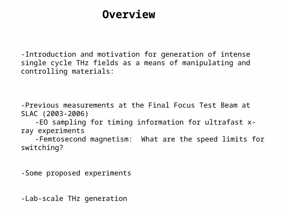
-Introduction and motivation for generation of intense single cycle THz fields as a means of manipulating and controlling materials:
-Previous measurements at the Final Focus Test Beam at SLAC (2003-2006)-EO sampling for timing information for ultrafast x-ray experiments-Femtosecond magnetism: What are the speed limits for switching?
-Some proposed experiments
-Lab-scale THz generation
-Parallel source after LCLS undulator
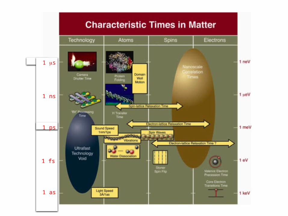
1 ms
1 ns
1 ps
1 fs
1 as


-Extreme electric fields: First steps in dielectric breakdown. What is the maximum fieldstrength a material can withstand?
-Long-distance transmission lines
-Extreme fields in nanoscale devices, integrated circuitry
-Magnetic fields: Highest peak fields generated in destructive explosive devices (~1000 T)
-Superconducting materials: Critical fields and currents.
Materials under Extreme Electromagnetic Fields
G. Crabtree et al.
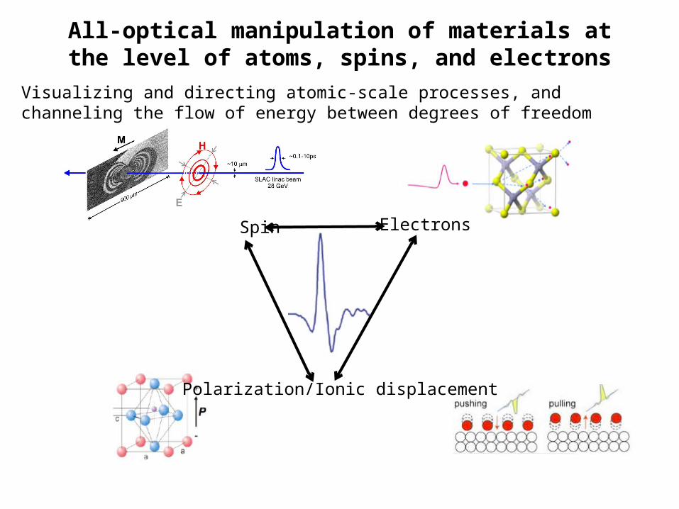
All-optical manipulation of materials at the level of atoms, spins, and electrons
Spin
Polarization/Ionic displacement
Electrons
Visualizing and directing atomic-scale processes, and channeling the flow of energy between degrees of freedom
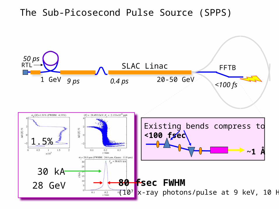
SLAC Linac
1 GeV 20-50 GeV
FFTBRTL
28 GeV30 kA
80 fsec FWHM(107 x-ray photons/pulse at 9 keV, 10 Hz)
1.5%
9 ps 0.4 ps <100 fs
50 ps
Existing bends compress to <100 fsec
~1 Å
The Sub-Picosecond Pulse Source (SPPS)

The SLAC Research Yard

Single-shot timing measurements

~ 200 fsτΔ
Single-Shot EOS Data at SPPS (100µm ZnTe)
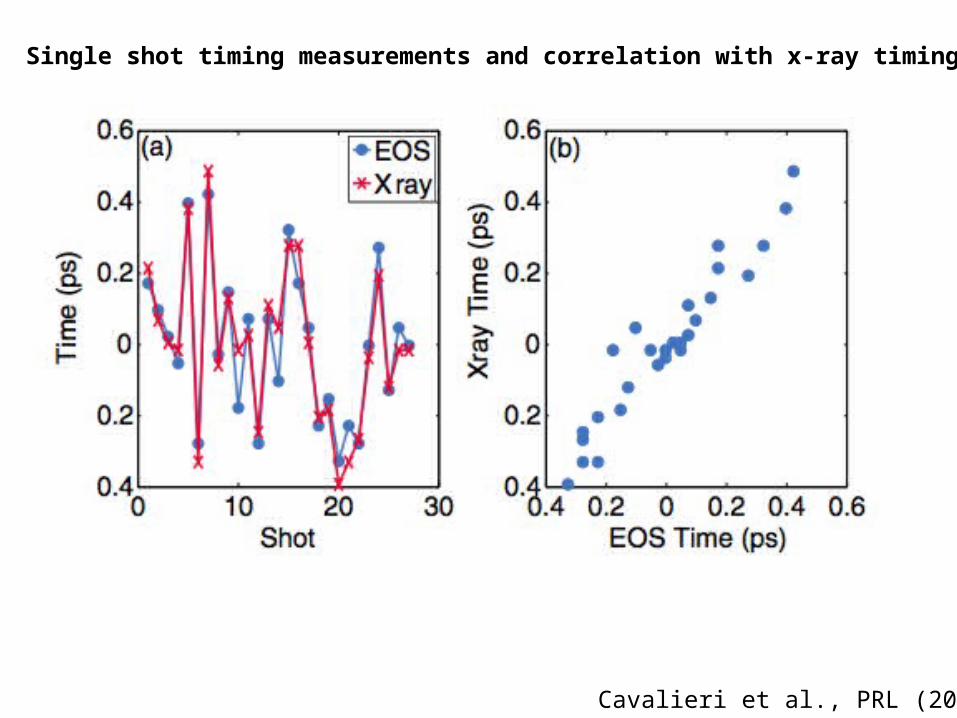
Cavalieri et al., PRL (2005)
Single shot timing measurements and correlation with x-ray timing

Lindenberg et al. PRL (2008)
Fritz et al. Science (2007)
Lindenberg et al. Science (2005)
Experiments

High-Field Effects in Metallic Ferromagnets on the Femtosecond TimescaleGoals:1. Study ultrafast magnetization dynamics induced by ultrastrong magnetic and electric fields
2. Study electrical transport and high field radiative effects excited by the fast, strong field pulses
Previous SLAC and FFTB Publications:
1. S.J. Gamble et. al., Electric field induced magnetic anisotropy in a ferromagnet, PRL 102, 217201 (2009)2. J. Stöhr et. al., Magnetization switching without charge or spin currents, APL 94, 072504 (2009)3. C. Stamm et. al., Dissipation of spin angular momentum in magnetic switching, PRL 94, 197603 (2005)4. I. Tudosa et. al., The ultimate speed of magnetic switching in granular recording media, Nature 428, 831 (2004)5. C.H. Back et. al., Magnetization reversal in ultrashort magnetic field pulses, PRL 81, 3251 (1998)6. C.H. Back et. al., Minimum field strength in precessional magnetization reversal, Science 285, 864 (1999)7. H.C. Siegmann et. al., Magnetism with picosecond field pulses, J. Mag. Mag. Mat. 151, L8 (1995)
Gamble, Stohr et al.

Open Questions
Magnetism:1. Do the properties of the electric field induced magnetoelectronic anisotropy change in different in-plane magnetic materials?2. Can we demonstrate the presence of a magnetoelectronic anisotropy in perpendicular materials?
Heating:
zooms
Magnetic Contrast Topographic
The longer, lower field picosecond length bunch heats the sample leading to the formation of stripe domains.
The picosecond bunch also ablates the sample and/or changes its chemical properties at the point of bunch impact.
The femtosecond pattern does not heat and is damage freeWhy???

Set-Up and Wish ListPrevious Set-Up at the FFTB
Manipulator arm andmotor controllers for sample movement
The beam and the samples pass through the six-way cross
Direction of theelectron beam
Wire Scanners to measurethe transverse beam profile
Sample Fork:10 samples are mounted at a time
Example sample parameters:0.5 mm insulating substrate (eg, MgO)10 nm thick magnetic thin film
Wish List (in rough order of importance):
For the beam:- Extremely well focused and well characterized pulses (essential!)- Ideal transverse beam size: <1-5 microns- Variable bunch lengths: 10-12 – 10-15 seconds- Variable bunch charge- 1 Hz repetition rate for sample exposure (30 Hz for measuring the transverse focus)
For the tunnel:- Ability to insert our set-up at the point of tightest beam focus- Downstream gamma ray detector for measuring the transverse beam profile (measuring the beam is essential!)- Sufficient ceiling height to insert our present manipulator and six-way cross (~6 feet)- Solid angle detector to measure emitted radiation from films in the backward direction
All of our experiments are single shot, and donot require an in-situ measurement technique –ie, with a well characterized beam we don’t need that much time per experiment!

All-optical Control of Ferroelectric Materials
Li et al., APL (2004)
Shin et al. Nature (2007)
-Ferroelectrics for non-volatile memory storage, sensors. What are the speed limits for switching?
-Phase transition behavior at the nanoscale
-Development of all-optical (electrode-less) techniques for manipulating and controlling materials
Korff Schmising et al., PRL (2007)

T=550 C (nanoscale stripe phase)
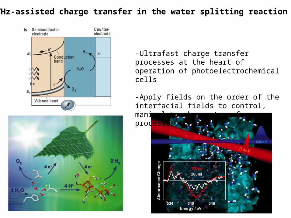
THz-assisted charge transfer in the water splitting reaction
-Ultrafast charge transfer processes at the heart of operation of photoelectrochemical cells
-Apply fields on the order of the interfacial fields to control, manipulate charge transfer processes.
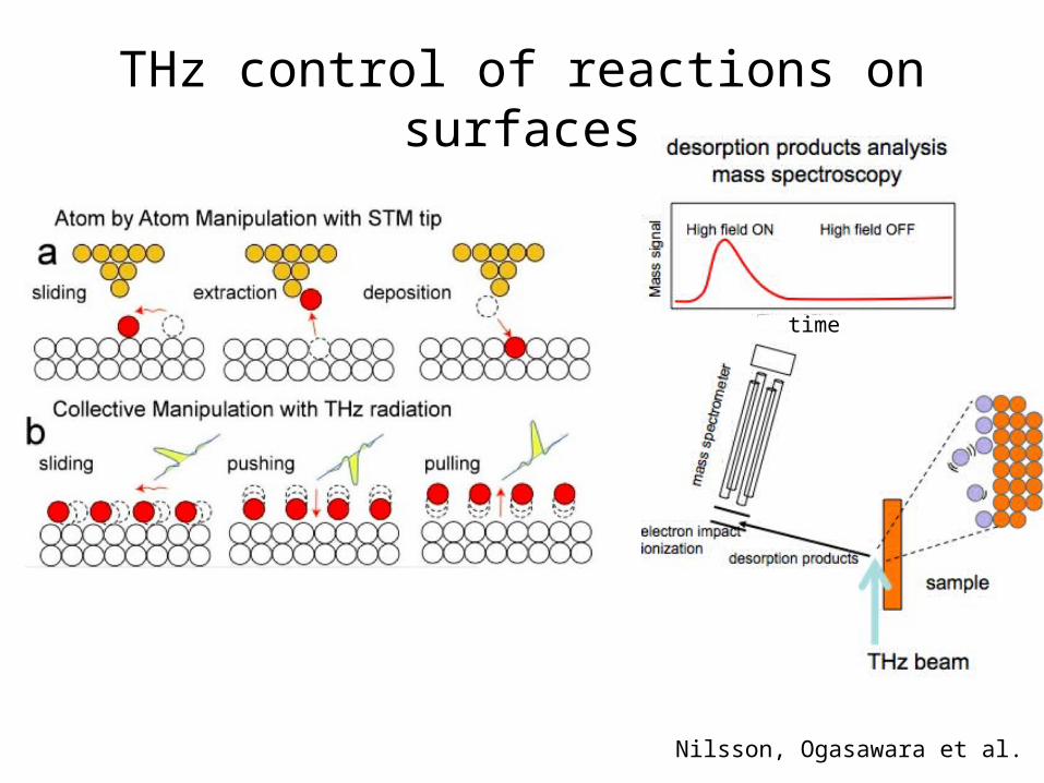
THz control of reactions on surfaces
time
Nilsson, Ogasawara et al.
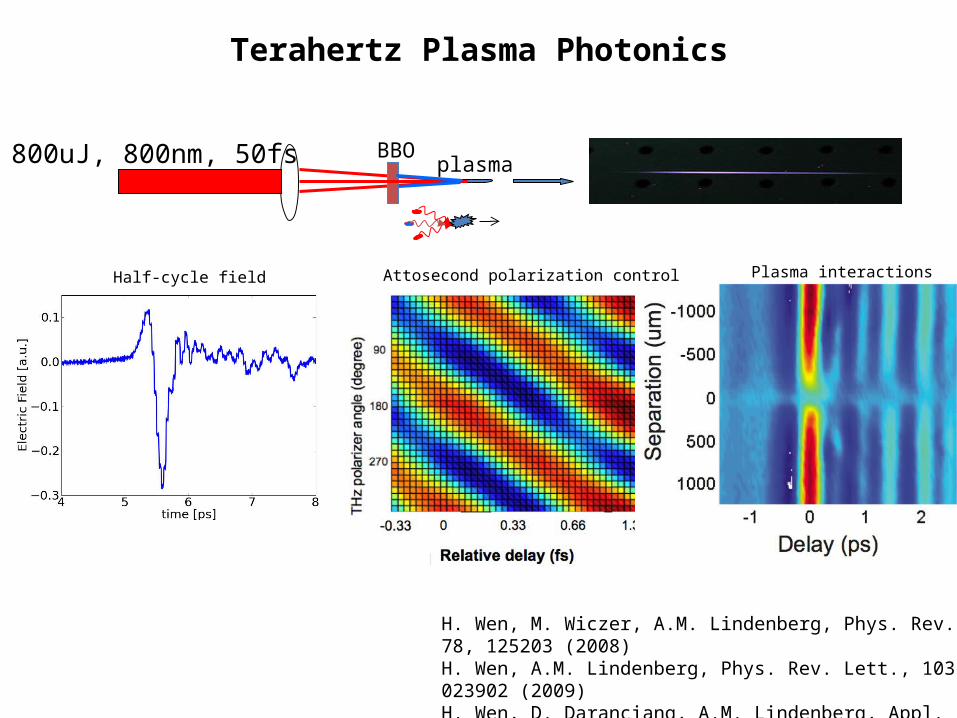
Terahertz Plasma Photonics
plasmaBBO800uJ, 800nm, 50fs
H. Wen, M. Wiczer, A.M. Lindenberg, Phys. Rev. B, 78, 125203 (2008)H. Wen, A.M. Lindenberg, Phys. Rev. Lett., 103, 023902 (2009)H. Wen, D. Daranciang, A.M. Lindenberg, Appl. Phys. Lett. (2010).
Half-cycle field Attosecond polarization control Plasma interactions

1D model of electron in asymmetric field
Phase control of THz polarity:
Xie et al., PRL (2006)

(sum over electron birth times)
Electron trajectories in transverse plane
Experiment
Theory

THz-induced breakdown processes/Directing charges in materials
H. Wen et al. PRB (2008)
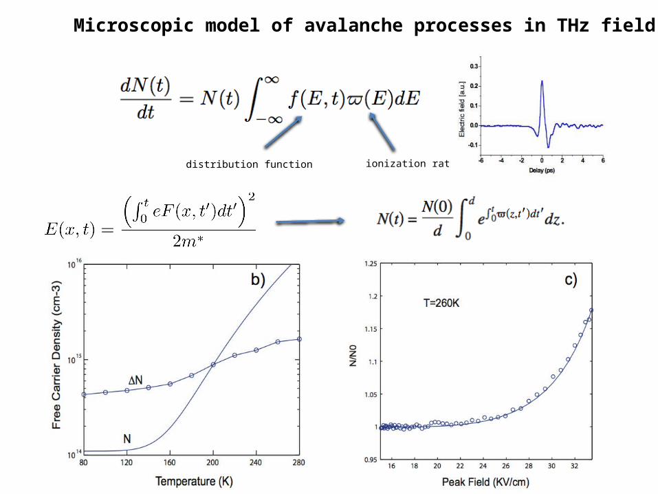
ionization ratedistribution function
Microscopic model of avalanche processes in THz field.
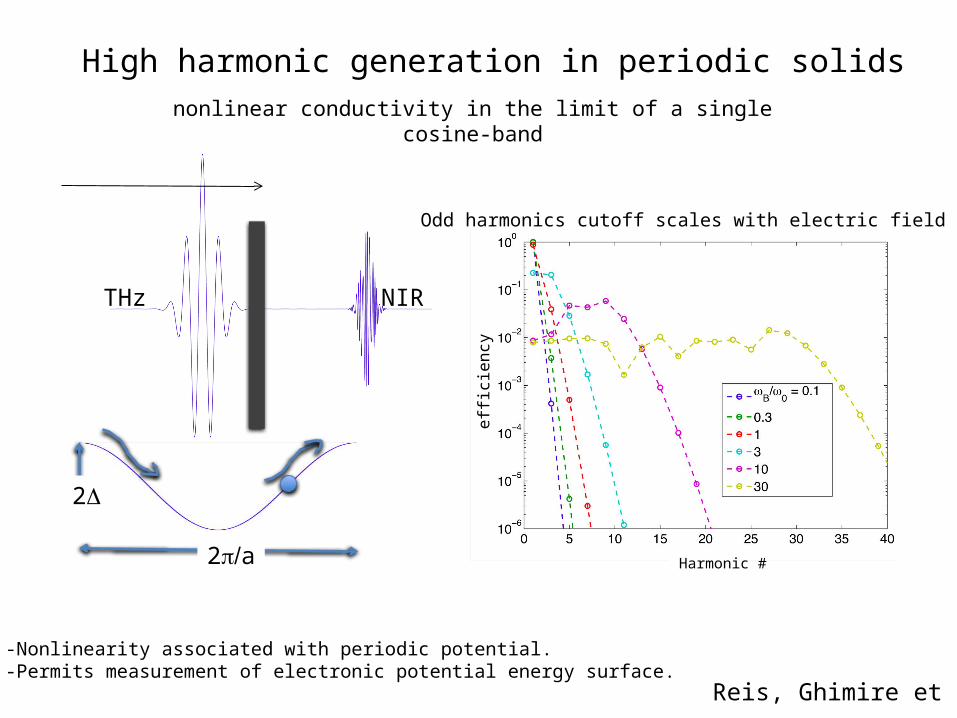
High harmonic generation in periodic solids
2D
2 /p a
THz NIR
nonlinear conductivity in the limit of a single cosine-band
Odd harmonics cutoff scales with electric field
-Nonlinearity associated with periodic potential. -Permits measurement of electronic potential energy surface.
Harmonic #
effici
ency
Reis, Ghimire et al.

Extraction of intense THz fields from relativistic electron bunches after the LCLS undulator
• Coherent transition radiation from x-ray transparent foil
• Electric fields approaching 300 MV/cm
• Peak magnetic fields of order 300 T
• Couple to LCLS x-ray experiments with THz transport line

Half rack Chiller
Pneumaticdrive
Cantilevered support
Earthquake braces (4X)
Existing bellows and stand
Relocated stand
Optical table
Existing beampipe, relocated
New beampipe
Beamline with Optical TableBefoil
Diamond window

Time (ps)
Rad
ius
(m
m)
-0.4 -0.2 0 0.2 0.4-1
-0.5
0
0.5
1
-0.4 -0.2 0 0.2 0.4-100
-50
0
50
100
150
Time (ps)
Ele
ctric
Fie
ld (
MV
/cm
)
-0.4 -0.2 0 0.2 0.4-5
0
5
10
15
Time (ps)
Cur
ren
t (k
A)
0 500 10000
20
40
60
80
100
Wavenumber (cm-1)
Fo
rmfa
ctor
(%
)
Calculations by H. Loos et al.
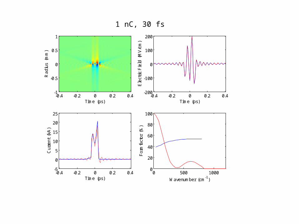
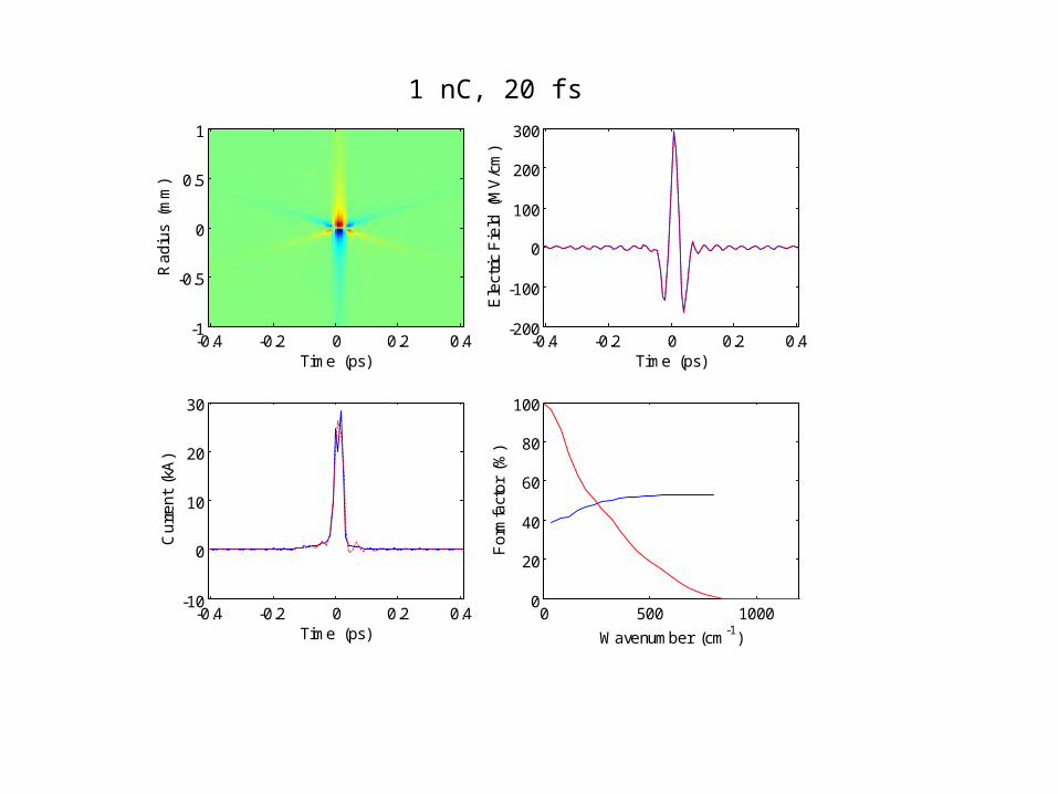
Simulations of THz field at focus
1 nC, 60 fs
Time (ps)
Rad
ius
(m
m)
-0.4 -0.2 0 0.2 0.4-1
-0.5
0
0.5
1
-0.4 -0.2 0 0.2 0.4-200
-100
0
100
200
Time (ps)
Ele
ctric
Fie
ld (
MV
/cm
)
-0.4 -0.2 0 0.2 0.4-5
0
5
10
15
20
25
Time (ps)
Cur
ren
t (k
A)
0 500 10000
20
40
60
80
100
Wavenumber (cm-1)
Fo
rmfa
ctor
(%
)
1 nC, 30 fs
Time (ps)
Rad
ius
(m
m)
-0.4 -0.2 0 0.2 0.4-1
-0.5
0
0.5
1
-0.4 -0.2 0 0.2 0.4-200
-100
0
100
200
300
Time (ps)
Ele
ctric
Fie
ld (
MV
/cm
)
-0.4 -0.2 0 0.2 0.4-10
0
10
20
30
Time (ps)
Cur
ren
t (k
A)
0 500 10000
20
40
60
80
100
Wavenumber (cm-1)
Fo
rmfa
ctor
(%
)
1 nC, 20 fs
Conclusions
• Unique opportunities for THz-manipulation of materials, using electromagnetic fields of strength not achievable in the laboratory
• Experiments will be carried out using samples placed directly in the electron beam as well as through use of extracted THz fields
• Real-time measurements are critical: Development of THz pump/optical probe; THz pump/THz probe geometries.