materials information service profiles - metallic... · the materials information service ... the...
TRANSCRIPT

MATERIALS INFORMATION SERVICE
The Materials Information Service helps those
interested in improving their knowledge of
engineering materials and highlights the
national network of materials expertise.
This Profile is one of a series produced by the
Materials Information Service.
For advice relating to your particular materials
problem, you can contact the MIS at:
The Materials Information Service
The Institute of Materials, Minerals and Mining
Danum House, South Parade
Doncaster DN1 2DY
Tel: 01302 320 486
Fax: 01302 380 900
MIS Profiles are produced by IOM Communications Ltd, a wholly owned subsidiary of the Institute of Materials, Minerals & Mining

Ref: 12/97
Introduction
Corrosion can be defined as the reaction of a material with its environment. Theproblem of corrosion arises in various environments ranging from urban and marineatmospheres to industrial chemical plant installations. It is a major factor governingthe design and operation of plant and equipment as it reduces their useful life andcan often result in unscheduled shutdowns or, in some cases, catastrophic failure.The control of corrosion presents a considerable challenge to engineers and, in spiteof our best efforts, the annual costs of corrosion damage and corrosion relatedservice failures run into many millions of pounds, estimated at about 4% of the GNPfor an industrial country. However, there is scope to reduce this cost burden bymaking improvements in materials selection, methods of protection, design and in-service monitoring.
In aqueous environments, corrosion may occur as uniform (general) or non- uniform(local) attack. Uniform corrosion results in general wastage, is reasonably easy toinspect and to predict from weight-loss experiments or electrochemical data. Localcorrosion can take a number of various forms and is much less predictable. It canresult in more serious damage to structures. In order to understand both general andlocal forms of wet corrosion of metallic materials, the role of oxide films on theirsurfaces must be considered. All metals except gold will have a surface air-formedoxide film, the nature of the film depending on alloy composition and the conditionsand temperature of its formation. Films which are strongly adherent and which do notcontain imperfections are protective and can protect the underlying substrate againstfurther dry oxidation or wet corrosive attack. Oxide films on the surfaces of metalsare therefore seen to play a significant part in the mechanism of aqueous corrosion,as illustrated by the rusting of mild steel. Failures so caused are difficult to preventdue to the complex nature of the interaction of different corrosion mechanisms andresidual and mechanical stresses in service. These mechanisms quite often giverise to non-uniform forms of corrosion which can result in severe local attach leadingto failure.
Rusting of mild steel
If mild steel is exposed to an aerated neutral aqueous solution, for example dilutesolution of sodium chloride in water, then corrosive attack will begin at defects in theoxide film on the steel. These defects may be present as a result of mechanicaldamage such as scratches, or may be due to natural discontinuities in the film, i.e.inclusions, grain boundaries or dislocation networks at the surface of the steel. At
METALLIC CORROSION
Dr John Pearce, The Central Test Centre Ltd

The hydroxyl ions react with the ferrous ions produced by the anodic reaction to formferrous hydroxide, which is then converted into a hydrated oxide called ’rust’.Gradually a scab of rust may form over the top of the pit, but this is too porous tocompletely block the anodic area. This allows the corrosion process to continue,resulting in deeper attack and a widening of the anodic area as the surface oxide filmbreaks away.
If the pH of the solution in contact with the steel is low, for example a dilute acid,then the surface oxide film will be removed and the cathodic reaction will be different.Hydrogen gas will be liberated as gradual dissolution of the steel occurs. Withoxidising acids, a number of alternate cathodic reactions may take place.
In all cases of corrosion the anodic reaction cannot proceed in isolation from thecathodic reaction and if either reaction can be limited or stopped then less or nocorrosion will occur.
Differential aeration
Uniform corrosion will tend to occur when some surface regions become anodic for ashort period, but their location and that of the cathodic regions constantly change.General rusting of mild steel will take place when there is a uniform supply of oxygenavailable across the surface of the steel and there is a uniform distribution of defectsin the oxide film (this is usually the case in the non protective films formed onunalloyed steel). In the absence of areas of high internal stress (cold-workedregions) or segregated zones (such as non-uniform distributions of sulphideinclusions), a number of anodic regions will develop across the surface. Someareas will become less active while new anodic regions become available.Therefore, overall attack takes place at a number of anodic sites whose positionsmay change, leading to general rusting across the surface.
If the supply of oxygen is not uniform across a surface then any regions which aredepleted in oxygen will become anodic, for example within a crevice, at a joint orbeneath a surface deposit. The remainder of the surface has oxygen available to itand therefore acts as a large cathodic area. When the cathodic area is so muchlarger, severe local attack will occur in the small anodic region. This can result in
each defect the steel is exposed to thesolution (electrolyte) and an anodicreaction occurs, resulting in the formationof iron ions and free electrons. Theseelectrons are then conducted through theoxide film to take part in a cathodicreaction at the surface of the film. Thisreaction requires the presence ofdissolved oxygen in the electrolyte andresults in the formation of hydroxyl ions,Figure 1. Fig. 1: Rusting of mild steel

perforation of a container or damaging local loss of load-bearing capacity instructural members. In motor cars local corrosion damage caused by mud and roaddirt (especially from salted roads) which is trapped inside bodywork provides an alltoo familiar example of the effects of differential aeration. Likewise, in partly-filledtanks corrosion becomes concentrated just below the wateriine, where there is apronounced fall in the oxygen availability and a short electron path to the water levelwhere hydroxyl ions are formed.
Crevice and deposit forms of corrosion can be minimised by correct design, forexample by the sealing of joints, by the prevention of deposits and fouling viaefficient maintenance and water treatment. The rate of supply of oxygen will governthe rate and mechanism of rusting. Differences in oxygen concentration can result inhighly localised damage. Without oxygen the cathodic reaction could not take place;hence in closed environments such as boiler and heating systems the removal ofoxygen from feedwaters by suitable treatment reduces the corrosion rate. In othersystems where the water is in contact with air corrosion in the system may bereduced by the addition of anodic or cathodic inhibitors to the water,
Cathodic inhibitors promote insoluble deposits which have an insulating effect andblock the flow of electrons, limiting the cathodic reaction and hence anodicdissolution. Anodic inhibitors assist film repair over the metal at anodic sites andhence passivate these areas. When using anodic inhibitors it is vital to maintain theircorrect concentration, since if the anodic sites are not completely blocked then theremaining exposed anodic area will be much smaller than before. The cathodicreaction is not affected and this will give higher current densities at the anode sites,causing highly localised attack called pitting and leading to rapid perforation ofsections.
Pitting
Pitting results from local breakdown of the barrier film which allows an anodicreaction to begin at point sites on the exposed metal. The cause of the point site
Severe local attack suchas pitting, Figure 2 andcrevice corrosion can bea particular problem instainless steels andother alloys whichdepend on the presenceof self- healing (whenoxygen is available),adherent and relativelydefect-free oxide filmsfor their resistance tocorrosion. Fig. 2: Pitting attack. (a) possible defect sites;
(b) growth from defects

may be local mechanical damage or chemical breakdown of the surface film, oxygendepletion beneath debris particles on the surface or chemical (galvanic effect)differences between second-phase particles or inclusions and the matrix.
Pitting is quite often self-accelerating due to local rises in acidity in the pits and isusually associated with the presence of certain ions, for example chloride andsulphide, in the corrosive environment. Such ions contribute to film breakdown andprevent film repair.
In stainless steels a minimum of 12% chromium is required in solid solution in thematrix to give passivation by protective oxide film formation. Nickel additions(normally 6-10%), molybdenum and nitrogen are also used to improve generalcorrosion and pitting resistance. They also help to control matrix structure, forexample to give austenitic or duplex grades. In these steels, carbon content is keptas low as possible during alloy production. Subsequent processing, welding and heattreatment variables are carefully controlled to avoid the formation of Cr-rich carbideprecipitates and other damaging second phases which can not only reducetoughness but also cause severe pitting and intergranular attack due to micro-galvanic effects.
A row of pits can form along deep scratches as the oxide film will not be imperviousand the underlying metal will contain additional internal stress. Larger pits can format dross and sand inclusions, highlighting the damaging effect of inadequate castingcleanliness. Casting defects such as shrinkage pores and inclusions can also resultin severe local attack,
To minimise pitting, stainless steels are solution treated and quenched to dissolvesecond phase precipitates and to prevent their reformation on cooling. Due to thepresence of chloride ions, conventional austenitic and duplex grades are prone toboth pitting and crevice corrosion in seawaters but their resistance can be improvedby additions of up to 6% Mo and 0.2-0.5% N.
The relative behaviour of various grades can be compared by an empiricalrelationship for Pitting Resistance Equivalent (PREN), based upon laboratorycorrosion tests in chloride containing solutions:
PREN = %Cr+3.3% Mo+X%N
where X = 16 for duplex and X = 30 for austenitic steels. The higher the PREN valuethe better the pitting resistance. Hence super-duplex and super-austenitic gradesgive PREN values of 40-50, lean alloy duplex 27-30 and 18/8 (type 304) austenitic avalue of about 20. For duplex structures, alloys are designed to produce ferrite andaustenite phases with the same pitting resistance to avoid preferential attack ofeither phase.
Research into pitting and the growth of corrosion fatigue and stress corrosion crackswhich are believed to originate at pits can now be aided by the use of specialtechniques which allow real-time mapping of local corrosion activity and the

determination of localised corrosion rates. Such information is essential in theaccurate prediction of safe working life.
Galvanic attack
Fig. 3: Galvanic attack
Table 1: Simplified galvanic series for metals and alloys. The relative position in agalvanic series will depend on the corrosive environment and on the passivity of the
surface of the metal or alloy.
Due to the potential differencethat develops when twodissimilar metals or alloys areconnected together in anaqueous solution the base metalwill become anodic and themore noble metal will act as acathode. The noble metal is, ineffect, cathodically protected bythe more reactive metal which iscorroded Figure 3.
A galvanic series of metals andalloys can be listed for givencorrosive environments, forexample seawater, to showwhich material is liable tocorrode in a galvanic couple,Table 1.

Attack on the base metal will usually be more severe at the junction with the noblemetal, but the extent of the damage will depend on the electrochemical differencesbetween them, i.e. the wider their separation in the galvanic series, the greater is theattack on the base partner. The relative surface areas of the two metals exposed tothe corrosive media and the nature of that media will also have an affect. Whensmall surface areas of base metal are connected to much larger areas of noblematerial the attack on the base metal will be rapid.
This is illustrated by the first recorded example of the galvanic effect with thedetachment of copper sheets from the hull of HMS Alarm in 1761. This was as aresult from attack on the iron nails which had been used to attach the copper to thetimbers.
Galvanic attack can be minimised, as can other forms of corrosion, by correctdesign. The use of galvanically compatible materials and the use of electricalinsulation between dissimilar materials will help. Not coating the anodic surface incase of pinhole damage to it is also useful as this could give rapid local attack.
The galvanic effect is the reason why different phases and segregated regions inalloy microstructures will have varying resistance to corrosion. This effect is madegood use of when polished specimens are selectively attacked by etching in orderto reveal and study microstructural features under the microscope. In stainlesssteels Cr-depleted zones around Cr-rich second phases will be less noble and assuch will be subject to highly localised attack, leading to interdendritic and/orintergranular forms of corrosion.
Intergranular attack Preferential local attackat grain boundaries in polycrystalline metalsarises due to the higher internal energy of thegrain boundary regions. This is enhanced bythe segregation of impurities to theboundaries and by the precipitation of secondphases which may be more noble and whichmay also lower the resistance of thesurrounding matrix by denudation. The extentof intergranular corrosion will depend on thelevel of sensitisation and the aggressivenessof the corrosive environment.
In austenitic stainless steel sensitisation dueto grain boundary precipitation of Cr carbidescan occur on heating in the temperaturerange 450¡- 900¡C, for example duringannealing or stress relieving, at service in thisrange or during welding, when it is calledWeld decay, Figure 4.
Fig. 4 . Schematic views ofintergranular corrosion inaustenitic stainless steel, forexample weld decay

Sensitisation can be reduced by use of very low carbon grades and by stabilisationby the addition of titanium or niobium. These elements have a greater affinity to formcarbides than chromium, hence any carbide precipitation that occurs will not removeCr from the matrix.
Leaching (selective corrosion)
The removal of one element from a solid solution alloy is often called leaching. Thegradual loss of zinc from brass (dezincification) is perhaps the most well-knownexample of this type of corrosion, but aluminium can also be leached from aluminiumbronzes (dealuminification) and nickel from 70/30 Cupronickel alloysdenickelification).
In each case initial corrosion dissolves both components of the alloy but the morenoble metal, copper, is then precipitated from solution at the surface. This leads toincreased solution of the parent alloy due to galvanic effects and hence furtherdeposition of copper. The overall effect is to reduce the surface and underlyingregions of a component to a spongy mass of material with much reduced mechanicalstrength, leading to possible collapse under normal working stresses.
Figure 5 (top) Leaching, (bottom) Selective attack
dimensions of components and pipes remain unaffected. This highlights theimportance of correct application of ultrasonic testing in the assessment of conditionof cast-iron sections which may have suffered this form of attack.
In water pipes both internal and external graphitisation may occur where soilchemistry is aggressive. Corrosion mechanisms will also be subject to the influence
The tendency to this form of attackcan be decreased by additionalalloying such as the addition ofarsenic to brass and nickel to Al-bronzes. Leaching and otherexamples of the selective attack areillustrated schematically in Figure 5.
A common form of leaching is thegraphitisation of cast-irons. In slightlyacidic waters both flake graphite(grey) and nodular graphite (ductile)irons are corroded due to the anodicbehaviour of the matrix with respectto the cathodic graphite. This resultsin the conversion of the structure to aweak porous mass of corrosionproduct and graphite residue.However, there is often little sign ofthe extent of this damage from theoutwards appearance of the material,since the original shape and

of microbiological activity. In some cases, in effluent lines and older water mains,pipe sections can be almost fully graphitised whilst still holding water. They havebeen severely weakened, however, and are prone to sudden failure if water pressurechanges, if supporting soil moves or vibration from overhead traffic increases.
The graphitised surface can be easily penetrated by a screwdriver or knife and theextent of the damage revealed by a examination under a microscope. Where it iscost-effective graphitisation is avoided by the use of high nickel austenitic cast- irons.
Corrosion and erosion
The combined effects of corrosion and erosive damage will arise when fluid velocityis high and when mechanical wear takes place due to abrasion by suspended solidparticles.
Protective surface films are more readily damaged and their repair by passivatingeffects are prevented. This leads to increased rates of local corrosion, calledimpingement attack, at areas of turbulence. The effect can be reduced by design tolower flow rates and to void sudden changes in flow direction.
Cavitation attack can occur in pump impellers and propellers when the collapse ofbubbles formed in the surrounding liquid can cause severe local damage at theirsurfaces. Vibration and other relative movement under load between surfaces canalso continually damage the oxide layers resulting in fretting corrosion, this caninitiate pitting and nucleate fatigue cracks.
Stress Corrosion Cracking (SCC)
The effects of residual and applied stresses and corrosive environments in serviceare closely interrelated. The more highly stressed (higher energy) regions of a metalwill become anodic and corrosive cells will be set up due to differences in localstress levels. Cold-worked regions, for example tube or sheet bends and cut edges,will be corroded in preference to uniform parts of sections in the same way that grainboundaries are attacked more than grain interiors on the microscopic scale.
The combined effects of stress and corrosion can result in a special type of failureknown as Stress Corrosion Cracking (SCC). This arises under a particular set ofcircumstances for a given alloy: specific alloy condition plus specific corrosive mediaand sufficient local tensile stress. Chloride-induced cracking of stainless, causticcracking of plain C-steels and ammonia damage to Cu-alloys are typical examples ofthis problem. The mechanism of SCC is shown as a simple representation in Fig 6.

Fig.6: Schematic view of Stress Corrosion Cracking (SCC) and Corrosion Fatiguecracks
SCC is believed to be nucleated at pitting damage sites and develops under theaction of local tensile stresses as a highly branched network of fine cracks. At eachcrack-tip the combined action of the tensile stress and specific ions in the corrosivemedia cause continual crack propagation with little evidence of local deformation.
In austenitic stainless steels, for example, warm chloride solutions in the presence ofresidual tensile stress can lead to cracking, SCC tendency is slight in low-Ni ferriticand martensitic grades but is severe in the 8-10% Ni austenitic steels. Duplexstainless steels have greater SCC resistance than austenitic since the duplexmicrostructure helps to inhibit the growth of SCC cracks, which tend to be deflectedor arrested at austenite-ferrite interfaces. Maximum resistance is obtained with 50/50austenite-ferrite microstructures and the dispersion of the two phases should be asfine as possible. The increased interest in the duplex grades stems not only fromtheir high pitting and SCC resistance but also from their higher proof stress levelwhich offers savings in material and weight over austenitic material.
Stress corrosion cracking presents an especially difficult problem, since not only is ithighly localised but it can occur in environments that are merely mildly corrosive tothe material. The damaging concentration of the harmful ions in that environmentmay be quite small and difficult to detect and, even in the absence of applied stress,residual stresses in a structure can often be of a sufficiently high level to cause SCCand failure in service.
In a given situation the time of exposure needed to cause SCC failure depends onthe stress intensity at any pre-existing or developed crack-tip. The concentration ofstress at the tip of a sharp crack or flaw can be quantified in terms of the StressIntensity Factor, K1C. It determines the growth-rate of SCC cracks for a specific alloy-environment combination. Catastrophic failure of a component will occur when thisfactor reaches a critical value, the Fracture toughness of the material, K1C. Thisenables the determination of allowable defect size in design to avoid failure undergiven loading conditions.
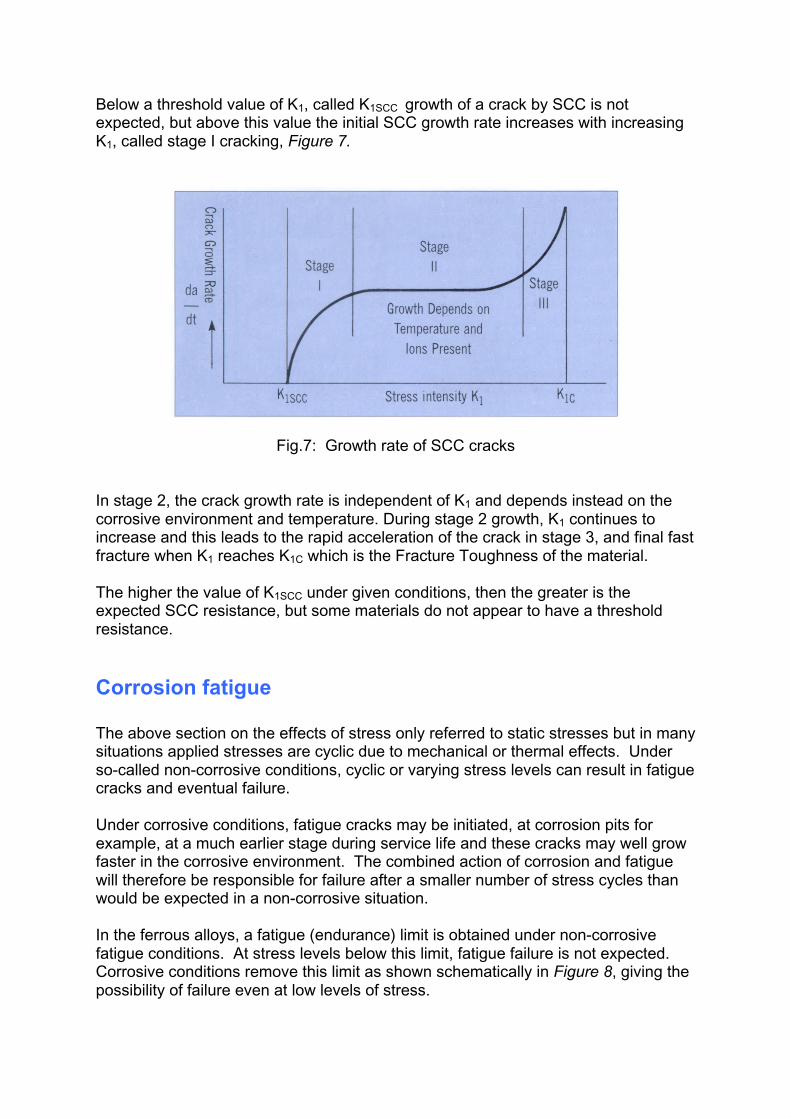
Below a threshold value of K1, called K1SCC growth of a crack by SCC is notexpected, but above this value the initial SCC growth rate increases with increasingK1, called stage I cracking, Figure 7.
Fig.7: Growth rate of SCC cracks
In stage 2, the crack growth rate is independent of K1 and depends instead on thecorrosive environment and temperature. During stage 2 growth, K1 continues toincrease and this leads to the rapid acceleration of the crack in stage 3, and final fastfracture when K1 reaches K1C which is the Fracture Toughness of the material.
The higher the value of K1SCC under given conditions, then the greater is theexpected SCC resistance, but some materials do not appear to have a thresholdresistance.
Corrosion fatigue
The above section on the effects of stress only referred to static stresses but in manysituations applied stresses are cyclic due to mechanical or thermal effects. Underso-called non-corrosive conditions, cyclic or varying stress levels can result in fatiguecracks and eventual failure.
Under corrosive conditions, fatigue cracks may be initiated, at corrosion pits forexample, at a much earlier stage during service life and these cracks may well growfaster in the corrosive environment. The combined action of corrosion and fatiguewill therefore be responsible for failure after a smaller number of stress cycles thanwould be expected in a non-corrosive situation.
In the ferrous alloys, a fatigue (endurance) limit is obtained under non-corrosivefatigue conditions. At stress levels below this limit, fatigue failure is not expected.Corrosive conditions remove this limit as shown schematically in Figure 8, giving thepossibility of failure even at low levels of stress.

Fig.8: Schematic curves for fatigue behaviour of a steel under non-corrosive andcorrosive conditions
Corrosion fatigue tends to produce a number of growing cracks, rather than the morenormal single crack in fatigue under conditions where corrosion has no influence.The corrosion fatigue cracks usually develop normal to the main tensile stress anddo not branch, whereas SCC cracks are highly branched.
Corrosion fatigue surfaces may or may not be coated with corrosion productdepending on the relative effects of corrosion and stress. There will be moreevidence of corrosion at lower stress levels or lower frequencies of stress cycling,because of the increased time of exposure. Unlike stress corrosion cracking,corrosion fatigue is a general problem and is not confined to a specific alloy-environment combination.
Hydrogen damage
Hydrogen can diffuse into metals and alloys from a number of sources during bothprocessing and subsequent service. These sources include dissociation of moistureduring casting and welding, thermal decomposition of gases and pickling and platingoperations. Hydrogen can also be generated from cathodic reactions duringcorrosion in service and from cathodic protection measures by sacrificial anodes andimpressed current.
The effects of hydrogen are well known in ferritic and martensitic steels, where it candiffuse to suitable sites in the microstructure and develop local internal pressureresulting in the characteristic form of hydrogen embrittlement.
Failure is time-dependent and occurs at low rates of strain as the load-bearing cross-section is reduced during slow crack growth in the embrittled region. Susceptibilityfor embrittlement is higher in alloys with higher yield strengths, i.e. those that arecold-worked, age-hardened or in the martensitic form. The sites at which hydrogenis trapped include the original austenite grain boundaries and the interfaces betweenthe matrix and nonmetallic inclusions, for example manganese sulphides. These

then result in both intergranular cracking (with separation at the prior austeniteboundaries) and transgranular cracking (flaking or quasi-cleavage) which isassociated with the inclusions.
In low-C steels, which have inherent ductility, hydrogen may not give cracking butwill cause blisters to develop at inclusions. This can lead to delamination in platedue to the directional nature of the inclusions.
Steels for sour gas service, where the environment contains wet hydrogen sulphide,must have very low sulphur levels or have been treated with additions to control theshape of the inclusions during deoxidation to minimise the danger of hydrogenembrittlement and blistering.
Hydrogen can assist in the propagation of corrosion fatigue cracks and can alsocause sulphide stress corrosion cracking in ferritic and martensitic steels, includingthe stainless grades.
Conclusion
Corrosion damage takes many forms resulting from a wide variety ofmaterial/environment/stress interactions.
In selecting materials to resist corrosion or taking corrosion protection measures,then total life-cycle cost is probably the’ most significant factor. In this respect, theextra costs for inspection, maintenance and earlier replacement of cheaper, lowercorrosion resistant materials have to be considered.
Materials have to be selected on the basis of their ability to resist specific corrosiveenvironments and to withstand the levels of service stresses. The ease of fabricatingthe materials into the shapes required by the design is also an importantconsideration.
In the design process, potential corrosion problems may be prevented by avoiding:
• shapes with crevices which might cause differential aeration• contact between incompatible materials which might give galvanic attack• situations where small anodic sites are in contact with large cathodic areas
Where to get advice
This is not an exhaustive list, but the following are often good starting points:
The Central Test CentreProspect RoadHalesowen B62 8DZTel/Fax: (+44) (0)121 585 7616

National Corrosion ServiceNational Physical LaboratoryTeddingtonMiddlesex TWII OLWTel: 0181 943 6179 Fax: 0181 943 6177
Institute of Corrosion4 Leek HouseLake StreetLeighton BuzzardBeds LU7 8TQTel: 01525 851771 Fax: 01525 376690
Cortest Laboratories Ltd56 Nursery StreetSheffield S3 8GPTel: 0114 275 2101 Fax: 0114 275 1989
Lithgow AssociatesThe Corrosion Centre87a Pennine wayFarnboroughHants GU14 9JATel: 01252 371173 Fax: 01252 372972
CAPCIS LtdBainbridge HouseGranby RowManchester MI 2PWTel: 0161 236 6573 Fax: 0161 228 7846
British Institute of Non-DestructiveTestingI Spencer ParadeNorthamptonNNI 5AATel: 01604 30124 Fax: 01604 231489
Further reading
Corrosion Resistance Tablesby Philip A Schweitzer.Marcel Dekker Inc.Vol I ISBN 0-8247-8372-7Vol 2 ISBN 0-8247-8373-5
CorrosionEd by LL Shreir.Newnes Butterworths.

ISBN 0-408-00109-7An Introduction to Metallic Corrosionby Ulrick B EvansEdward Amold Ltd.ISBN 0-7131-2758-9
Corrosion for Students of Science andEngineeringby KR Trethaway & J ChamberlainLongman Scientific & Technical.ISBN 0-582-45089-6
Source:This document is based on 'Corrosion-alayman's guide' first published in Insight',the journal of the British Institute of NDT,Vol. 39 Vol January 1997.