materials selection for concrete overlays : information survey
TRANSCRIPT
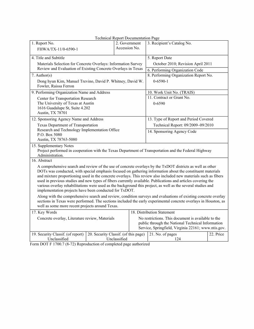
Technical Report Documentation Page
1. Report No.
FHWA/TX-11/0-6590-1
2. Government Accession No.
3. Recipient’s Catalog No.
4. Title and Subtitle
Materials Selection for Concrete Overlays: Information Survey Review and Evaluation of Existing Concrete Overlays in Texas
5. Report Date
October 2010; Revision April 2011
6. Performing Organization Code 7. Author(s)
Dong hyun Kim, Manuel Trevino, David P. Whitney, David W. Fowler, Raissa Ferron
8. Performing Organization Report No.
0-6590-1
9. Performing Organization Name and Address
Center for Transportation Research The University of Texas at Austin 1616 Guadalupe St, Suite 4.202 Austin, TX 78701
10. Work Unit No. (TRAIS) 11. Contract or Grant No.
0-6590
12. Sponsoring Agency Name and Address
Texas Department of Transportation Research and Technology Implementation Office P.O. Box 5080 Austin, TX 78763-5080
13. Type of Report and Period Covered
Technical Report: 09/2009–09/2010
14. Sponsoring Agency Code
15. Supplementary Notes Project performed in cooperation with the Texas Department of Transportation and the Federal Highway Administration.
16. Abstract
A comprehensive search and review of the use of concrete overlays by the TxDOT districts as well as other DOTs was conducted, with special emphasis focused on gathering information about the constituent materials and mixture proportioning used in the concrete overlays. This review also included new materials such as fibers used in previous studies and new types of fibers currently available. Publications and articles covering the various overlay rehabilitations were used as the background this project, as well as the several studies and implementation projects have been conducted for TxDOT.
Along with the comprehensive search and review, condition surveys and evaluations of existing concrete overlay sections in Texas were performed. The sections included the early experimental concrete overlays in Houston, as well as some more recent projects around Texas.
17. Key Words
Concrete overlay, Literature review, Materials
18. Distribution Statement
No restrictions. This document is available to the public through the National Technical Information Service, Springfield, Virginia 22161; www.ntis.gov.
19. Security Classif. (of report) Unclassified
20. Security Classif. (of this page) Unclassified
21. No. of pages 124
22. Price
Form DOT F 1700.7 (8-72) Reproduction of completed page authorized

Materials Selection for Concrete Overlays: Information Survey Review and Evaluation of Existing Concrete Overlays in Texas Dong hyun Kim Manuel Trevino David P. Whitney David W. Fowler Raissa Ferron CTR Technical Report: 0-6590-1 Report Date: October 2010; April 2011 Project: 0-6590 Project Title: Materials Selection for Concrete Overlays Sponsoring Agency: Texas Department of Transportation Performing Agency: Center for Transportation Research at The University of Texas at Austin Project performed in cooperation with the Texas Department of Transportation and the Federal Highway Administration.
iv
Center for Transportation Research The University of Texas at Austin 1616 Guadalupe St, Suite 4.202 Austin, TX 78701 www.utexas.edu/research/ctr Copyright (c) 2010 Center for Transportation Research The University of Texas at Austin All rights reserved Printed in the United States of America
v
Disclaimers Author's Disclaimer: The contents of this report reflect the views of the authors, who
are responsible for the facts and the accuracy of the data presented herein. The contents do not necessarily reflect the official view or policies of the Federal Highway Administration or the Texas Department of Transportation (TxDOT). This report does not constitute a standard, specification, or regulation.
Patent Disclaimer: There was no invention or discovery conceived or first actually reduced to practice in the course of or under this contract, including any art, method, process, machine manufacture, design or composition of matter, or any new useful improvement thereof, or any variety of plant, which is or may be patentable under the patent laws of the United States of America or any foreign country.
Notice: The United States Government and the State of Texas do not endorse products or manufacturers. If trade or manufacturers' names appear herein, it is solely because they are considered essential to the object of this report.
Engineering Disclaimer NOT INTENDED FOR CONSTRUCTION, BIDDING, OR PERMIT PURPOSES.
Project Engineer: Dr. David W. Fowler
Professional Engineer License State and Number: Texas No. 27859 P. E. Designation: Research Supervisor

vi
Acknowledgments The researchers acknowledge the invaluable assistance provided by Clifford Halvorson,
TxDOT project director for Project 0-6590. Also appreciated is the guidance provided by German Claros and Ryan Barborak with TxDOT.
vii
Table of Contents Chapter 1. Introduction................................................................................................................ 1
1.1 Information Survey Review ...................................................................................................1 1.2 Condition/Evaluation Surveys in Texas ................................................................................1
Chapter 2. Overview of Concrete Overlays Types .................................................................... 3 2.1 Whitetopping .........................................................................................................................3
2.1.1 Purpose and Uses ........................................................................................................... 3 2.1.2 Performance Factors ...................................................................................................... 3 2.1.3 Common Modes of Failure ............................................................................................ 4
2.2 Bonded Concrete Overlay ......................................................................................................4 2.2.1 Purpose and Uses ........................................................................................................... 4 2.2.2 Performance Factors ...................................................................................................... 4 2.2.3 Common Modes of Failure ............................................................................................ 5
2.3 Unbonded Concrete Overlay .................................................................................................5 2.3.1 Purpose and Uses ........................................................................................................... 5 2.3.2 Performance Factors ...................................................................................................... 5 2.3.3 Common Modes of Failure ............................................................................................ 5
Chapter 3. Materials Selection ..................................................................................................... 7 3.1 Cement ...................................................................................................................................7
3.1.1 High-Strength Concrete (Ref 4) ..................................................................................... 7 3.2 Aggregates .............................................................................................................................7
3.2.1 Coarse Aggregates (CA) ................................................................................................ 8 3.2.2 Fine Aggregates (FA) .................................................................................................... 8 3.2.3 Gradation ........................................................................................................................ 8
3.3 Fly Ash ...................................................................................................................................9 3.4 Slag ........................................................................................................................................9 3.5 Silica Fume ............................................................................................................................9 3.6 Admixtures .............................................................................................................................9
3.6.1 Air Entrainment ............................................................................................................. 9 3.6.2 High Range Water Reducers (HRWR) ........................................................................ 10 3.6.3 Shrinkage Reducers (SRA) .......................................................................................... 10 3.6.4 Retarders ...................................................................................................................... 10
3.7 Reinforcements ....................................................................................................................10 3.7.1 Wire Mesh .................................................................................................................... 10 3.7.2 Reinforcement Bars (Ref 4) ......................................................................................... 10 3.7.3 Fibers ............................................................................................................................ 12
3.8 Bonding Agents (Ref 11) .....................................................................................................13 3.8.1 Grout ............................................................................................................................ 14 3.8.2 Epoxy ........................................................................................................................... 15 3.8.3 Shear Connectors or “Jumbo Nails” ............................................................................ 15
3.9 Incidental Materials (Ref 4) .................................................................................................15 3.9.1 Dowel Bars ................................................................................................................... 15 3.9.2 Tie Bars ........................................................................................................................ 15 3.9.3 Joint Sealant Materials ................................................................................................. 16

viii
3.10 Separation Layer Material for UBCOs ..............................................................................16
Chapter 4. Mixture Design/Proportioning ............................................................................... 17 4.1 Cementitious Materials Content ..........................................................................................17 4.2 Water-to-Cementitious Materials Ratio (w/cm) ..................................................................17 4.3 Fly Ash Content ...................................................................................................................17 4.4 Aggregate Ratio ...................................................................................................................17 4.5 Fiber Content .......................................................................................................................18 4.6 Air Entrainment Content ......................................................................................................18 4.7 Admixture Dosage ...............................................................................................................18
Chapter 5. Construction ............................................................................................................. 19 5.1 Environmental Limitations ..................................................................................................19 5.2 Surface Preparation ..............................................................................................................19
5.2.1 Bonded Concrete Overlay ............................................................................................ 20 5.2.2 Whitetopping/UBCO ................................................................................................... 22
5.3 Surface Cleaning ..................................................................................................................22 5.4 Fiber Incorporation ..............................................................................................................23 5.5 Placement .............................................................................................................................24 5.6 Jointing .................................................................................................................................25 5.7 Curing (Ref 11) ....................................................................................................................25
Chapter 6. Analysis of Forensic and Evaluation Studies in Texas ......................................... 27 6.1 Forensic Study of BCO on IH 10 in El Paso (Ref 45) .........................................................27 6.2 Forensic Study of BCO on IH 30 in Fort Worth (Ref 46) ...................................................27 6.3 Evaluation Study of First BCO in Texas .............................................................................28 6.4 Evaluation Study of Second BCO in Texas .........................................................................29 6.5 Evaluation Study of Third BCO in Texas ............................................................................29
Chapter 7. Review of Other State and RILEM Reports ......................................................... 31 7.1 Reports from Other States ....................................................................................................31
7.1.1 Virginia (Ref 51) .......................................................................................................... 31 7.1.2 Missouri (Ref 23) ......................................................................................................... 32 7.1.3 Louisiana (Ref 29) ....................................................................................................... 33 7.1.4 Illinois (Ref 28) ............................................................................................................ 34 7.1.5 Iowa (Ref 52) ............................................................................................................... 34
7.2 Review of RILEM Report ....................................................................................................35 7.2.1 Materials Consideration ............................................................................................... 35 7.2.2 Construction Procedures .............................................................................................. 35 7.2.3 Curing .......................................................................................................................... 36
Chapter 8. Condition/Evaluation Surveys in Texas ................................................................ 37 8.1 Houston—SH 146 and SH 225 ............................................................................................37
8.1.1 SH 146 Survey ............................................................................................................. 37 8.2 Houston—Beltway 8 ............................................................................................................39
8.2.1 Condition Survey ......................................................................................................... 39 8.3 Houston—IH 610 North ......................................................................................................40
8.3.2 Condition Survey ......................................................................................................... 42 8.4 Houston—IH 610 South ......................................................................................................42
ix
8.5 Sherman—US 75 (Pre-construction) ...................................................................................45 8.5.1 Existing Pavement ....................................................................................................... 45 8.5.1 Proposed Overlay ......................................................................................................... 46 8.5.1 US 75 Survey ............................................................................................................... 46
8.6 Sherman—US 75 (Construction) .........................................................................................46 8.6.1 Surface Preparation and Placement of Reinforcements ............................................... 47 8.6.2 Construction ................................................................................................................. 50 8.6.3 Finishing and Curing .................................................................................................... 51 8.6.4 Conclusion ................................................................................................................... 53
8.7 Wichita Falls—US 281 ........................................................................................................53 8.7.1 Condition Survey ......................................................................................................... 53
8.8 Laredo—IH 35 .....................................................................................................................55 8.8.1 IH 35 Whitetopping Construction ................................................................................ 56 8.8.1 Condition Survey Results ............................................................................................ 57 8.8.1 Previous Condition Surveys ......................................................................................... 58 8.8.1 Discussion and Recommendations .............................................................................. 60
8.9 El Paso—IH 10 ....................................................................................................................61 8.9.1 Condition Survey ......................................................................................................... 62
Chapter 9. Conclusions ............................................................................................................... 63 9.1 Materials Selection ..............................................................................................................63 9.2 Materials Design ..................................................................................................................63 9.3 Construction Methods ..........................................................................................................64
9.3.1 Environmental Limitations .......................................................................................... 64 9.3.2 Surface Preparation ...................................................................................................... 64 9.3.3 Surface Cleaning .......................................................................................................... 65 9.3.4 Fiber Incorporation ...................................................................................................... 65 9.3.5 Placement ..................................................................................................................... 65 9.3.6 Jointing ......................................................................................................................... 66 9.3.7 Curing .......................................................................................................................... 66
References .................................................................................................................................... 69
Appendix A .................................................................................................................................. 75
Appendix B .................................................................................................................................. 79
Appendix C .................................................................................................................................. 83
Appendix D .................................................................................................................................. 85
Appendix E .................................................................................................................................. 91
Appendix F .................................................................................................................................. 97
Appendix G ................................................................................................................................ 101
Appendix H ................................................................................................................................ 105
Appendix I ................................................................................................................................. 107

x
xi
List of Figures
Figure 3.1: Experiment on reinforcement location ....................................................................... 11
Figure 3.2: Steel placed directly on top of substrate ..................................................................... 12
Figure 3.3: Spraying grout immediately ahead of paver ............................................................... 14
Figure 3.4: Purpose of interlayer .................................................................................................. 16
Figure 5.1: Cooling down the prepared surface before placement ............................................... 22
Figure 5.2: Cleaning the surface with hydrocleaning equipment ................................................. 23
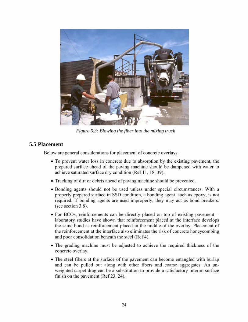
Figure 5.3: Blowing the fiber into the mixing truck ..................................................................... 24
Figure 5.4: Failed joints in wheel path.......................................................................................... 25
Figure 5.5: Prompt curing following the paver ............................................................................. 26
Figure 8.1: Layout of IH 610 North experimental sections .......................................................... 41
Figure 8.2: Typical section of US 75 in Sherman ......................................................................... 45
Figure 8.3: Typical section of the proposed BCO ........................................................................ 46
Figure 8.4: Prepared surface prior to the yellow stripe removal ................................................... 47
Figure 8.5: After the removal of the yellow stripe........................................................................ 48
Figure 8.6: Reinforcement detail .................................................................................................. 48
Figure 8.7: Transition reinforcement detail .................................................................................. 49
Figure 8.8: Transition reinforcement detail close-up .................................................................... 49
Figure 8.9: A worker spraying water on the surface ..................................................................... 50
Figure 8.10: Concrete too far ahead of the paving machine ......................................................... 51
Figure 8.11: Dried surface around concrete .................................................................................. 51
Figure 8.12: Carpet dragging, tining, and spraying curing compound ......................................... 52
Figure 8.13: Laying down burlaps ................................................................................................ 52
Figure 8.14: Crack spacing distribution ........................................................................................ 57
Figure 8.15: Average cracking spacing by station ........................................................................ 58
Figure 8.16: Crack spacing distribution ........................................................................................ 59
Figure 8.17: Average crack spacing with time by station ............................................................. 60

xii

xiii
List of Tables
Table 5.1: Surface preparation procedures ................................................................................... 20
Table 8.1: SH 146 survey—northbound direction ........................................................................ 38
Table 8.2: SH 146 survey—southbound direction ........................................................................ 38
Table 8.3: Beltway 8 survey—westbound direction ..................................................................... 40
Table 8.4: Beltway 8 survey—eastbound direction ...................................................................... 40
Table 8.5: Experimental section factorial (Section number) ........................................................ 41
Table 8.6: Summary of condition survey on IH 610 North .......................................................... 42
Table 8.7: South Loop factorial for 1983 BCO experiment ......................................................... 43
Table 8.8: South Loop IH 610 experimental factors for 1989–1990 BCO ................................... 44
Table 8.9: US 281 survey—southbound direction ........................................................................ 54
Table 8.10: US 281 survey—eastbound direction ........................................................................ 55
Table 8.11: Summary of crack spacing results ............................................................................. 59
Table 8.12: Summary of westbound condition survey on IH 10 .................................................. 62
Table 8.13: Summary of eastbound condition survey on IH 10 ................................................... 62

xiv
1
Chapter 1. Introduction
This technical report is divided into two parts: Information Survey Review and Condition Surveys/Evaluation of the Existing Overlays in Texas. These two topics were the first two tasks performed for CTR Project 0-6590: Materials Selection for Concrete Overlays.
1.1 Information Survey Review
The purpose of the information survey review is to gather and organize information about the current state of knowledge on the material selection, mixture design/proportioning, and construction for portland cement concrete overlays (herein referred to as concrete overlays). This task involved conducting a comprehensive literature review on concrete overlays applications by the Texas Department of Transportation (TxDOT) as well as other states, with special emphasis focused on gathering information about the constituent materials, mixture design/proportioning, and recommended construction methods. The research team also reviewed performance and characteristics of fibers used in overlays for concrete paving and for bridge deck applications.
1.2 Condition/Evaluation Surveys in Texas
Several existing concrete overlays in Texas were surveyed to evaluate their current condition. TxDOT districts were contacted to find out about concrete overlay projects that were performed in the past and any upcoming projects. Once contacts were established with the districts, researchers visited the project sites with their assistance to survey the area. Condition surveys include following sites.
Houston – SH 146 and SH 225
Houston – Beltway 8
Houston – IH 610 North
Houston – IH 610 South
Sherman – US 75 South (Pre-construction)
Sherman – US 75 South (Construction)
Wichita Falls – US 281
Laredo – IH 35
El Paso – IH 10

2
3
Chapter 2. Overview of Concrete Overlays Types
The term “concrete overlay” is used when a layer of portland cement concrete (herein referred to as concrete) is used to resurface an existing pavement as a rehabilitation method. Concrete overlays in Texas are categorized in three ways: whitetopping, bonded concrete overlay, and unbonded concrete overlay. A fourth category, partially bonded overlays, is not discussed in this report because it is not used for highway applications in Texas.
2.1 Whitetopping
The term “whitetopping” indicates a concrete overlay that is used to resurface an existing asphalt pavement. Whitetoppings are subcategorized by the thickness and the bond conditions. There are three types: ultra-thin, thin, and conventional.
2.1.1 Purpose and Uses
The purposes of whitetopping are to rehabilitate deteriorating asphalt pavements, to increase load capacity and improve ride quality. Because whitetoppings do not develop typical distresses that are found in asphalt pavements, it is a good alternative to placing an asphalt overlay.
Ultra-thin Whitetopping (UTW): This type of application typically consists of a 2 to 4-in.-thick concrete overlay and is used when the existing pavement is considered to be in fair or better condition with minor surface distresses (shoving, rutting, alligator cracking, etc.). The overlay relies on existing pavement to carry much of the load and good bond will promote monolithic behavior. Monolithic behavior reduces flexural stresses in the overly, which can lead to early cracking and failure. UTWs are generally used in light traffic applications.
Thin Whitetopping (TWT): Identical to UTW, but in this application the overlay is thicker (typically around 5 to 8 in.) and is used when the existing pavement is considered to be more deteriorated than for UTW requirements. The overlay relies on existing pavement to carry some of the load by monolithic behavior through bond. TWTs are generally used when moderate traffic is present.
Conventional Whitetopping (CWT): This concrete overlay is typically 9 in. or thicker and is used when the existing pavement is in severely deteriorated condition. CWT design assumes unbonded condition, so the existing pavement is expected to serve only as a subbase. The new overlay will carry the entire traffic load. CWTs are generally used when heavy traffic is of concern.
2.1.2 Performance Factors
Following factors determine the performance of whitetoppings.
Effectiveness of bond: Properly achieved bond will promote monolithic behavior. This behavior is crucial in ensuring that the stiffness of the rehabilitated pavement (overlay and existing pavement) will carry the traffic load as one structure.
4
Existing pavement condition: Because UTWs and TWTs rely on the existing pavement to assist in carrying the traffic load, the condition of the existing pavement affects the performance of the rehabilitated pavement. Proper repairs or upgrades should be made to the substrate to provide adequate support as required by design.
Proper joint spacing: If joints are made, well designed joint spacing helps to reduce curling stresses and bending stresses due to traffic loads. This is especially true for UTW and TWT because of their thinness.
2.1.3 Common Modes of Failure
Following failure modes are commonly seen in whitetoppings.
Loss of bond: The bond between the overlay and the existing pavement can be lost due to lack of quality control in surface preparation or placement during construction.
Rapid transition zone failure: Accelerated deterioration in the transition zones can occur where asphalt and the concrete overlay meet. Thicker concrete overlay sections are recommended in these areas (Ref 1).
2.2 Bonded Concrete Overlay
The term bonded concrete overlay (BCO) is used to categorize relatively thin concrete overlays that are used to resurface an existing concrete pavement. This type of overlay is typically 2 to 4 in. thick and its performance depends on good bond to the existing pavement.
2.2.1 Purpose and Uses
The purpose of BCO is to rehabilitate deteriorating concrete pavements to increase load capacity and ride quality. BCO is recommended when the existing pavement is considered to be in fair or better condition with minor surface distresses.
2.2.2 Performance Factors
Assuming adequate flexural strengths of at least 500 psi are achieved in the BCO mixture, the following factors determine the performance of BCOs.
Effectiveness of bond: Proper bond will provide monolithic behavior, ensuring that the stiffness of the rehabilitated pavement (overlay and existing pavement) will carry the traffic load as one structure.
Existing pavement condition: Because BCOs rely on the existing pavement to assist in carrying the traffic load, the condition of the existing pavement affects the performance of the rehabilitated pavement. Proper repairs or upgrades should be made to provide adequate support as required by design.
Proper joint spacing: If joints are made, well designed joint spacing helps to reduce curling stresses and bending stresses due to traffic and environmental loads. It is crucial that the transverse joints in the BCOs match those in the existing pavement to promote monolithic behavior.
5
2.2.3 Common Modes of Failure
The following failure modes are commonly seen in BCOs.
Loss of bond: The bond between the overlay and the existing pavement can be lost due to lack of quality control during construction, especially in the surface preparation.
Delamination due to difference in Coefficient of Thermal Expansion (CTE): If BCO has a CTE that is equal to or greater than the CTE of the existing pavement, then the overlay will expand or contract more than the existing pavement. This results in shear stresses forming in the bond, and these induced stresses can cause the overlay to crack and delaminate.
Higher stresses at boundaries: Boundary conditions in BCOs at the edges of the overlay and along cracks are higher than in the bonded areas away from them. The effect is highest at the very edge and diminishes rapidly to the standard uniformly distributed stresses. This due to curling and warping stresses in the top of the overlay as temperatures and moisture conditions change more rapidly there than in the rest of the slab depth.
2.3 Unbonded Concrete Overlay
The term unbonded concrete overlay (UBCO) is used to categorize relatively thick concrete overlays that are used to resurface the existing concrete pavement. This type of overlay is typically 5 to 11 in. and is designed to perform without bonding to the existing pavement.
2.3.1 Purpose and Uses
The purpose of UBCO is to rehabilitate deteriorating concrete pavements, improving load capacity and ride quality. UBCO is used when the existing pavement is severely deteriorated with major surface distresses.
2.3.2 Performance Factors
The following factors determine the performance of UBCOs.
Effectiveness of the separation layer: An effective separation layer will act as a shear plane that will prevent cracks from reflecting up from the existing pavement into the overlay. In addition, the separation layer provides a level support surface on top of severely deteriorated existing pavement for the overlay construction.
Effective drainage: A well constructed drainage system will prevent the building up of pore pressure from the traffic loads. The system serves to prolong the life of the overlay by reducing pumping, asphalt stripping of the separation layer, faulting, and cracking.
2.3.3 Common Modes of Failure
The following failure modes are commonly seen in UBCOs.
Failure to consider at-grade and overhead structures: The elevation of the pavement after an UBCO placement will significantly increase. Therefore, at-grade and
6
overhead structures should be raised, or existing pavement should be removed and replaced near these structures (Ref 2).
Inadequate separation layer: The separation layer prevents reflective cracks from occurring. If the new overlay is not structurally separated from the deteriorated existing pavement, the movement of two structures will be dependent, which will induce heavy reflective stress to the overlay from underneath.
Poor drainage: The higher elevation of the pavement necessitates a change in the drainage grade lines. Additional right-of-way may be required to provide the proper slopes for the ditches (Ref 3).
7
Chapter 3. Materials Selection
This chapter discusses general guidelines for materials selection for concrete overlays. Following these guidelines will ensure that appropriate materials are chosen for each type of concrete overlays.
3.1 Cement
The most commonly used cement types are Type I, Type I/II, and Type III. Type I is usually used because this type of cement develops less heat of hydration, avoiding many of the problems associated with high temperature development (Ref 4, 5).
When high early strength is desired, a Type III or more finely ground Type I cement is used. However, the use of these cements will result in an increased heat of hydration and caution should be taken to reduce thermal cracking. Other characteristics to consider when selecting cement are long-term mechanical properties, toughness, volume stability, and long life in severe environments (Ref 4, 6).
Where local sulfate contamination of the roadway is an issue, Type II or V cements are desirable because they are resistant to sulfate attack and have lower heat of hydration than other cements. Strength gain and set time may be regulated with admixtures and mixture proportioning (Ref 7, 8).
To prevent alkali-silica reaction (ASR), low alkali cement should be used for any type of cement. When siliceous aggregates are used, alkalis from cement react to form expansive gel causing deleterious effects. Cement should contain low alkali content and SEM substitutions to prevent from ASR from occurring.
3.1.1 High-Strength Concrete (Ref 4)
High-early-strength concrete is appropriate for opening overlays to traffic in ≤24 hours, but normal strength concrete may be used if traffic loading may be delayed for 48 or 72 hours. For larger projects, where paving continues to 72 hours or more before traffic loading begins, normal-strength mixtures can be used and high-strength mixtures used for the last day’s construction. This will maximize economy while permitting early traffic on the pavement. Abrasion resistance and durability should also be considered and may favor the use of high-strength concrete with fly-ash or slag replacement.
When the time for opening to traffic is an issue, rapid strength concrete mixtures with high cementitious materials content, low water to cementitious materials ratio, smaller top size aggregate, and synthetic fibers can be used to expedite the construction process (Ref 4, 9).
3.2 Aggregates
To construct an efficient concrete overlay, the aggregate should be adequately strong, physically stable, and chemically stable. The aggregates make up between 65 and 75% of the total concrete volume; therefore, their properties have a definite influence on those of the concrete.
Available aggregates should be evaluated carefully to determine which best meet early age and long term performance requirements. Performance requirements may justify purchase of more expensive (high-strength, crushed) aggregates, or careful aggregate blending (Ref 10). Aggregates that conform to Item 421 of TxDOT Standard Specifications Should be used, but

8
extensive laboratory testing on trial mixes or demonstrated field performance is required to ensure selection of suitable aggregates.
To prevent ASR, non-reactive aggregates should be selected. Many durability problems result from the reaction between the silica in the aggregates (e.g., siliceous river gravel) and alkalis contained in the cement (Ref 11).
Unsaturated absorptive aggregates have a higher moisture demand and can contribute to debonding during curing. These aggregates will absorb available moisture, hindering the curing procedure and affecting shrinkage (Ref 4, 10, 12).
3.2.1 Coarse Aggregates (CA)
The maximum CA size is a function of the overlay thickness. It is recommended that the largest practical maximum CA size is used in order to minimize paste requirements, reduce shrinkage, minimize costs, and improve mechanical interlock properties at joints and cracks (Ref 4, 9). Maximum CA sizes of 0.75 to 1 in. have been commonly used, but the reduction in size may be necessary for thinner overlays. For non-reinforced pavement structures, a maximum aggregate size of one-third of the slab thickness is recommended (Ref 5, 4, 11). The lowest allowable maximum aggregate size specified should be 0.5-in.
In the case of BCO, the compatibility of materials between the old concrete and the new concrete is fundamental for the success of the bond. The CTE of the concrete overlay should be less or at least similar to that of the existing pavement (Ref 10, 18, 42). This is because higher slab stresses and wider joint openings can occur when aggregates with higher CTE are used (Ref 8). Because the CTE of the overlay is governed by the coarse aggregate properties, the CTE of the coarse aggregates used in the overlay should be less or at least similar to that of the existing pavement. Significant difference should be avoided in order to reduce the differential movement.
Also, the elastic modulus should be lower than that of the existing pavement, for BCOs (Ref 11). It is recommended that the coarse aggregate in the BCO should have a thermal coefficient no higher than that of the coarse aggregate in the existing pavement. For instance, it is advisable to utilize a limestone aggregate for the BCO concrete if the existing concrete has siliceous river gravel as coarse aggregate, because of the limestone’s lower thermal coefficient, but the opposite arrangement will make up for an overlay prone to delamination (Ref 11).
3.2.2 Fine Aggregates (FA)
FA must be sound and nonreactive. It is necessary that FA be sufficiently resistant to tire wear (polishing) to prevent loss of skid resistance. The polish resistance may be improved by using durable and angular fine aggregates (Ref 4, 6, 10).
3.2.3 Gradation
Using uniformly and densely graded aggregates is recommended to reduce shrinkage because it reduces required paste. This is helpful in thin concrete overlays, because the risk of debonding due to shrinkage and curling potential is decreased (Ref 10). Both the top size and gradation of the aggregate will also affect aggregate interlock at the joint, which is another important consideration, because thin concrete overlay joints are typically not dowelled (Ref 8).
9
3.3 Fly Ash
Cement may be partially replaced with fly ash. Use of Class C fly ash leads to higher ultimate concrete strengths and lower permeability (Ref 7). Due to the lower specific gravity of fly ash, as compared to cement, replacement of cement with fly ash increases the volume of cementitious paste in the mixture. This increased volume of paste provides an improved coating of fibers and aggregate in the mixture, leading to improved workability and fiber distribution (Ref 4).
Although it generates less strength at early ages than Class C fly ash, Class F fly ash should also be considered for concrete overlays. The reasons are that Class C fly ash is typically not as effective as Class F fly ash in mitigating ASR, and, also, Class C fly ash will generate more heat of hydration than Class F fly ash.
3.4 Slag
For concrete overlays, slag cement is typically used in replacement proportions of 25 to 35%. It is normally substituted for cement on a one-to-one basis by mass. The proportion of slag cement is usually dictated by requirements for strength, durability, time of set, and the resistance of the concrete to ASR. Mixtures should be optimized for strength and durability using trial batches and the appropriate test methods. It is not uncommon to find that total cementitious material can be reduced by using appropriate levels of slag cement to replace cement when strength is used as the evaluating criteria.
3.5 Silica Fume
Generally, addition of silica fume will increase the compressive strength. However, an unbalanced addition will attract agglomerated silica fume particles to provide fast crack propagation path within the matrix (Ref 13). Higher compressive strengths usually mean higher modulus for concrete, and that may not be desirable in thin overlays on very low-modulus asphalt substrates.
Also, typically, silica fume is relatively expensive, rarely available, and difficult to handle, so the use of silica fume is not recommended for overlays.
3.6 Admixtures
Typical admixtures used in concrete overlays include air entrainment, high range water reducers, and retarders. When combinations of these admixtures are used, their combined effects should be observed. Care must be taken to avoid any admixtures that cause unnecessary reduction in the rate of strength gain. In all cases, preliminary bond tests should be conducted with similar concretes—both with and without the chemical admixtures—to ensure that comparable bond strengths are obtained at early ages (Ref 5).
3.6.1 Air Entrainment
Air entrainment protects the hardened concrete from freeze-thaw damage and deicer scaling. Air entrainment also helps increase the workability of fresh concrete, significantly reducing segregation and bleeding (Ref 4).
10
3.6.2 High Range Water Reducers (HRWR)
HRWRs can make concrete with a low ratio of water to cementitious materials workable enough for placement (Ref 10). This allows for a lowering of the w/cm, while maintaining a desired slump. This has the beneficial effect of increasing strength and reducing permeability, while keeping good workability. Whenever fibers are used in concrete overlays, using HRWR is highly recommended.
3.6.3 Shrinkage Reducers (SRA)
Although SRAs are not in common use yet for concrete overlays, they offer considerable potential for reducing overlay stresses and thus providing additional safety against cracking and debonding (Ref 10). Shrinkage reducing admixtures have shown to reduce both the time to first crack and the overall cracking (Ref 14, 15, 16). Incorporation of SRAs can reduce plastic shrinkage cracking substantially by lowering the evaporation rate, delaying the peak capillary pressure due to the development of menisci in the pores, and decreasing settlement (Ref 17). The downside of using SRAs is their high cost. Further research in this area is highly recommended.
3.6.4 Retarders
Retarders delay set in hot weather, and may be combined with HRWR in a single admixture (Ref 10). Using retarders in cold weather is not recommended.
3.7 Reinforcements
Because concrete is weak in tension, proper reinforcements can be added to increase the performance of concrete overlays. Reinforcement installation is a time-consuming aspect of construction; therefore, careful planning is needed to minimize time spent while maximizing benefits from using reinforcements.
3.7.1 Wire Mesh
Based on an evaluation survey done on IH 610 in Houston, welded wire mesh fabric provides more effective restraint on concrete volume change potential than steel fibers (Ref 18). The increase in volume change restraint can achieve better bond between concrete overlay and the existing pavement. Wire mesh is relatively easier to install than reinforcement bars; however, it still takes careful placement and notable additional construction time compared to using fibers.
3.7.2 Reinforcement Bars (Ref 4)
When reinforcement bars are placed in concrete overlays, typically No. 5 and No. 6 bars are used for longitudinal and transverse reinforcement. Larger bar sizes are likely to cause segregation of the coarse aggregates and voids in the mixture. It is recommended that No. 5 or No. 6 bars should be used.
11
BCO Application Steel bars can be placed directly over the surface of the existing pavement, rather than at
mid-depth of the overlay. The performance of the steel has been demonstrated to be the same, but placing it on top of the existing pavement saves construction time and costs, because it is much easier and economical to lay it over the surface than to place it on chairs at mid-depth (Ref 11).
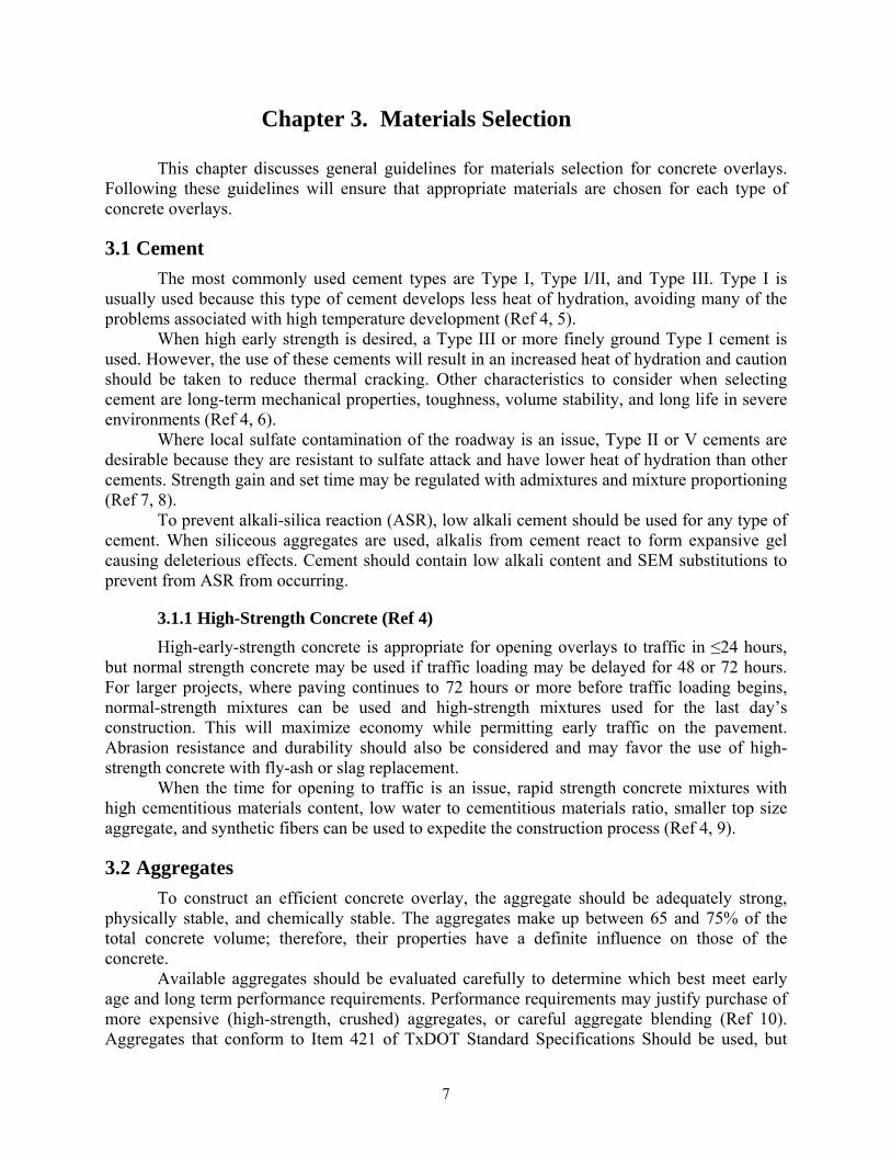
An experiment was conducted at Center for Transportation (CTR) at The University of Texas at Austin to determine the effect of the steel position on its bonding to the concrete (Ref 43). Two types of concrete slabs were cast in the laboratory. The first group consisted of 12 slabs, 12-in. by 12-in. by 3-in.-thick. Steel bars were laid on the 3-in.-thick base, after the surfaces were scarified and before placing an overlay. For the second set of slabs, 12 more specimens were cast, this time placing the steel at mid-depth. All slabs were cured under normal laboratory conditions. Schematics of both types of specimens are shown in Figure 3.1.
Figure 3.1: Experiment on reinforcement location
The test consisted of pulling the steel bars from the slabs. All bars failed in tension before they could be pulled out from the slab, showing that its bond strength is higher than the steel tensile strength, regardless of the position of the bars. From the test, it is inferred that the bars will not fail in anchorage, even when placed directly on the surface of an existing pavement. Therefore, the reinforcement steel can be placed directly on the surface, as is shown in Figure 3.2, saving construction time, labor, and money. Furthermore, the reinforcement placed directly on top of the substrate helps to restrain the movement of the new concrete slab due to environmental changes, which, in turn, improves the bond between both pavement layers. The steel will restrain concrete volume changes at the interface most effectively, which will prevent or retard debonding. It is most desirable that strains near the interface be minimized.
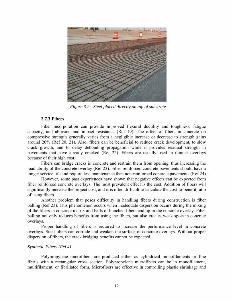
12
Figure 3.2: Steel placed directly on top of substrate
3.7.3 Fibers
Fiber incorporation can provide improved flexural ductility and toughness, fatigue capacity, and abrasion and impact resistance (Ref 19). The effect of fibers in concrete on compressive strength generally varies from a negligible increase or decrease to strength gains around 20% (Ref 20, 21). Also, fibers can be beneficial to reduce crack development, to slow crack growth, and to delay debonding propagation while it provides residual strength in pavements that have already cracked (Ref 22). Fibers are usually used in thinner overlays because of their high cost.
Fibers can bridge cracks in concrete and restrain them from opening, thus increasing the load ability of the concrete overlay (Ref 23). Fiber-reinforced concrete pavements should have a longer service life and require less maintenance than non-reinforced concrete pavements (Ref 24).
However, some past experiences have shown that negative effects can be expected from fiber reinforced concrete overlays. The most prevalent effect is the cost. Addition of fibers will significantly increase the project cost, and it is often difficult to calculate the cost-to-benefit ratio of using fibers.
Another problem that poses difficulty in handling fibers during construction is fiber balling (Ref 23). This phenomenon occurs when inadequate dispersion occurs during the mixing of the fibers in concrete matrix and balls of bunched fibers end up in the concrete overlay. Fiber balling not only reduces benefits from using the fibers, but also creates weak spots in concrete overlays.
Proper handling of fibers is required to increase the performance level in concrete overlays. Steel fibers can corrode and weaken the surface of concrete overlays. Without proper dispersion of fibers, the crack bridging benefits cannot be expected.
Synthetic Fibers (Ref 4)
Polypropylene microfibers are produced either as cylindrical monofilaments or fine fibrils with a rectangular cross section. Polypropylene microfibers can be in monofilament, multifilament, or fibrillated form. Microfibers are effective in controlling plastic shrinkage and
13
settlement cracking. The fibrillation process greatly enhances the bonding between the concrete and the polypropylene fibers and can provide residual strength in pavement that has already cracked (Ref 6).
Polypropylene macrofibers are coarse fibers that allow greater surface area contact within the concrete, resulting in increased interfacial bonding and flexural toughness. Polypropylene macrofibers can be used as secondary reinforcement and can provide greater post-crack strength and concrete slab capacity. Additional benefits include improved impact, abrasion, and shatter resistance.
Polyester fibers are available only in monofilament form. They commonly have relatively low fiber content and are used to control plastic shrinkage-induced cracking. Synthetic fibers do not absorb water and therefore do not affect the mixing requirements.
Steel Fibers (Ref 4)
Steel fibers are primarily made of carbon steel, although stainless steel fibers are also manufactured. Perhaps the biggest advantage of steel fibers is their high tensile strength and their ability to bridge joints and cracks to provide tighter aggregate interlock, resulting in increased load-carrying capacity. Steel fiber-reinforced pavements exhibit excellent toughness and pre- and post-crack capacity (Ref 19).
The aspect ratio is an important parameter influencing the bond between the concrete and the fiber, with longer fibers providing greater bond strength and toughness, often at the expense of workability. Steel fibers may also have certain geometric features to enhance pullout or anchorage within the concrete mixture. These features may include crimped or hooked ends or surface deformations and irregularities.
Blended Fibers (Ref 4)
Blended fiber systems combine macrofibers with microfibers or steel fibers. The microfibers in these systems provide resistance to plastic shrinkage and settlement cracking, while the macrofibers or steel fibers provide long-term secondary reinforcement. Blended systems provide higher levels of fatigue resistance, greater flexural toughness, and improved durability. Additional benefits include improved impact, abrasion, and shatter resistance.
3.8 Bonding Agents (Ref 11)
Bonding agents, e.g., portland cement grout, latex modified portland cement grout, and epoxy resins, are sometimes used to improve bond. However, bonding agents cannot compensate for bad substrate surface preparation and may act as a bond breaker when used inappropriately; therefore it is not recommended to use bonding agents unless under special circumstances. The use of bonding agents leads to two interfaces and thus to the creation of two possible planes of weakness instead of one. In addition, grout often has a high water-cement ratio leading to low strength and the risk of a cohesive failure within the bonding agent itself.
Under normal placement conditions, the performance of the BCOs and whitetoppings is better if no bonding agent is utilized (Ref 25), as long as the surface has adequate texture and has been cleaned as to be completely dry and free of dust, white water, and other debris. Moreover, the bonding at the interface becomes less critical as the BCO thickness increases. This is because

14
the thicker the BCO, the less it relies on the existing pavement to carry the load. However, under special conditions, additional means to assure good bonding can be utilized.
The shear strength at the bond interface should be at least 1.4 MPa (200 psi) (Ref 11, 26). Bond strength can be improved by increased surface roughness, which exposes aggregates to lock the layers together (Ref 1).
3.8.1 Grout
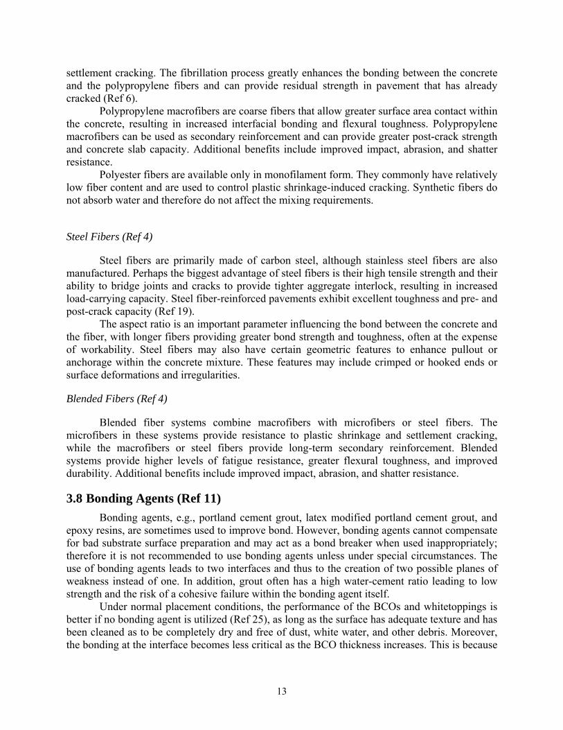
If the surface happens to be wet, a concrete grout will assure better bond strength. If a grout is used, the overlay should be placed before the grout dries; otherwise, the bond strength of the overly may be significantly reduced, because dried grout increases the probability of delamination by acting as a bond breaker (Ref 11). Past experiences have shown that grouting is not needed especially when the existing surface has been milled and cleaned well. A cleaned and properly moistened surface is enough to ensure proper BCO bonding.
Figure 3.3 shows that, immediately before paving, a grout can be uniformly broomed over the full width of the prepared surface. Nevertheless, it would be much safer if the construction can wait until the surface is dry. Typically the water-to-cement ratio of the grout is around 0.62 to 0.70 by weight, or approximately seven gallons of water per sack of cement (Ref 27).
Figure 3.3: Spraying grout immediately ahead of paver
There are reports that grout has the potential to slightly improve bond strength (Ref 28). However, if used properly with a clean, textured surface, good bond can be achieved (Ref 29). Nevertheless, placing grout is just an additional step that will slow the paving process. The BCO placed in Houston, on the South Loop (Ref 36), showed that dry grout could act as a bond breaker between the existing pavement and the overlay: the experimental sections where the grout was used and allowed to dry prior to the paving of the overlay caused early delaminations. The overlay in those sections had to be removed shortly after construction. Because the grout is not needed when the surface preparation and cleaning are adequate, its use is not recommended, as it could cause debonding.

15
3.8.2 Epoxy
For a condition when the surface texture has been treated only by a less expensive surface roughening procedure and, therefore, is not rough enough to guarantee an adequate bond, liquid epoxy materials have been reported to provide extremely high bonding strengths in the laboratory (higher than 5000 psi) (Ref 30). When epoxy is used, it is very important to apply the epoxy immediately ahead of paving. If not, the epoxy will harden and act as a bond breaker, which will cause a very expensive repair.
3.8.3 Shear Connectors or “Jumbo Nails”
Use of shear connectors or “jumbo nails” can effectively controlled development of the overlay drying shrinkage cracks at early age (Ref 31). These nails are installed along the pavement edges and longitudinal saw cuts—the areas more susceptible to debonding. Nails are installed on the original pavement prior to the overlay placement. Installation consists of a three-step process: drilling, drill-hole cleaning, and nail driving. The high-strength steel nails are driven into the predrilled holes in the existing pavement by an actuator that makes use of an explosive charge. The top part of the nail remains out of the existing pavement to be covered by the concrete overlay when the new concrete is cast.
Similar to shear connectors, curb-type reinforcement bars epoxied into the existing pavement surface have been used successfully to prevent edge curling and warping (Ref 29). Usage of nails is at about 6-in. part from the edge or joint, with spacing between nails of 15 to 30-in. Smaller nail spacing results in a higher number of cracks of smaller width.
3.9 Incidental Materials (Ref 4)
It is not practical to install dowel bars, tie bars, or keyway in thin concrete overlays because of the lack of concrete coverage. Field evaluation has indicated that the load transfer provided by aggregate interlock is generally high because of the joint spacing and the support provided by the asphalt layer. (Ref 1, 23) However, dowel bars, tie bars, and key ways play an important role in improving the load transfer efficiently in UBCO applications when just aggregate interlock is not enough. Unlike whitetoppings or BCOs, UBCO offers thicker layer of concrete so that these material can stay safely embedded.
3.9.1 Dowel Bars
Typically, billet steel, grade 60 bars that conform to ASTM A615 or AASHTO M31 are used. Sometimes the sizes are reduced. The recommended number and spacing of dowels is the same as those for new pavements. In general, uniform 12-in. spacing is recommended, but non-uniform spacing has also been used successfully. In the non-uniform dowel spacing design, the dowels are concentrated in the wheel paths (Ref 4, 32).
3.9.2 Tie Bars
Typically, billet steel, grade 40 bars that meet ASTM A615 or AASHTO M31 specifications are used.
16
3.9.3 Joint Sealant Materials
If used, joint sealant materials are (1) hot-poured rubberized materials conforming to ASTM D660, AASHTO M301, or per normal design, (2) silicone materials conforming to a governing state specification, or (3) reformed compression seals conforming to ASTM D2628, AASHTO M220, or a governing state specification. When small panel sizes are constructed, sealant is often not used.
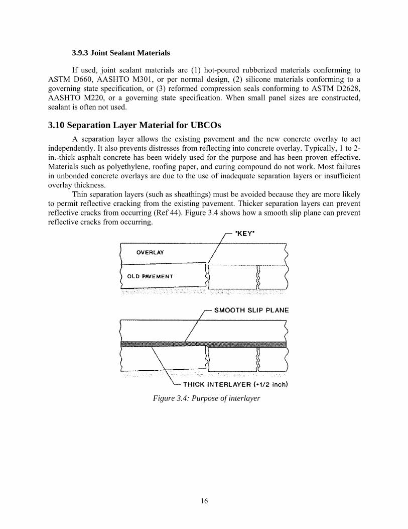
3.10 Separation Layer Material for UBCOs
A separation layer allows the existing pavement and the new concrete overlay to act independently. It also prevents distresses from reflecting into concrete overlay. Typically, 1 to 2-in.-thick asphalt concrete has been widely used for the purpose and has been proven effective. Materials such as polyethylene, roofing paper, and curing compound do not work. Most failures in unbonded concrete overlays are due to the use of inadequate separation layers or insufficient overlay thickness.
Thin separation layers (such as sheathings) must be avoided because they are more likely to permit reflective cracking from the existing pavement. Thicker separation layers can prevent reflective cracks from occurring (Ref 44). Figure 3.4 shows how a smooth slip plane can prevent reflective cracks from occurring.
Figure 3.4: Purpose of interlayer
17
Chapter 4. Mixture Design/Proportioning
Once the potential materials are selected, proper design/proportioning of those materials is very important to ensure desired concrete overlay performance. In this section, brief discussions for each design/proportioning criteria and recommendations are given.
4.1 Cementitious Materials Content
A concrete overlay must have enough cementitious paste to coat the aggregates, have enough workability, and coat the interface layer (Ref 6, 7). An insufficiency of cementitious material content can lead to low early strength. However, using too much cementitious paste will increase the chance of durability issues such as shrinkage and akali-silica reaction (ASR) and issues caused by high heat of hydration. Based on publications, as high as 7 to 7.5 sack of cement content is recommended (Ref 10, 23, 29).
4.2 Water-to-Cementitious Materials Ratio (w/cm)
Lower w/cm values are often used for concrete overlays to minimize drying shrinkage. However, lack of water leads less than ideal amount of paste formation and can hinder coating the aggregates, having enough workability, and coating the interface layer (Ref 6, 7). The low w/cm of the El Paso BCO concrete, coupled with a very dry surface, is thought to have contributed to overlay debonding. However, too much water can increase the chance of shrinkage, increase heat of hydration, and increase evaporation rate (Ref 12, 15). Higher the water content, the greater the potential for shrinkage as the water evaporates (Ref 4, 18).
For normal placement, 0.40 to 0.45 w/cm is recommended and maximum of 0.35 w/cm is recommended for expedited placement.
4.3 Fly Ash Content
A study showed that addition of Class C Fly-ash resulted in increased cracking in the cement replacement range of 0 to 15%. However, beyond this replacement rate, one can expect beneficial effects of fly ash addition. In other words, there appears to be a threshold cement replacement rate (around 20%) at which beneficial effects of fly-ash addition on shrinkage cracking occurs (Ref 15). A 30% replacement of cement with fly ash improved workability, reduced heat of hydration, increased long-term strength, and enhanced resistance to environmental attack. Too much fly ash will reduce short term strength gain. At least 25% of fly ash replacement is recommended.
4.4 Aggregate Ratio
Because cement shrinks and expands more than aggregates, using as much aggregate as possible while using as little cement possible is beneficial (while meeting other requirements). An increase in the aggregate/cement (a/c) ratio was highly effective in reducing shrinkage cracking (Ref 15). Also, the performance changes in concrete due to varying coarse/fine aggregate ratio need to be studied.
18
4.5 Fiber Content
Addition of fibers impacts water demand and workability. Changes to water content and/or water-reducing admixture dosage will be required for adequate workability. The severity of these changes will be dependent on fiber type and fiber dosage rate (Ref 19). A main factor that will determine the content or even the usage of fiber at all will be the economic feasibility. Cost–benefit analysis will need to be performed to determine if or which fibers can reduce long-term cost (obviously, short-term is going to be much higher).
Each type of fiber has recommended dosage from the manufacturer. Typical amounts of synthetic fibers used are at least 0.1% by volume or around 3 lb/yd³. Normal steel fiber contents are approximately 0.25% to 2% by volume or 33 to 265 lb/yd³.
Numerous studies have shown indefinite trend of compressive and/or tensile strength change due to the addition of fibers (Ref 19, 21, 23, 33). There were instances where the strengths increased, decreased, or stayed the same. For each project, amount of fiber desired should be calculated in terms of cost and required strength. TxDOT has developed minimum average residual strength (ARS) requirement by performing ASTM C1399.
4.6 Air Entrainment Content
Enough air must be entrained for durability as required per project. Typically, 4 to 7% of air is entrained depending on project specifications. The interaction between air entrainment and other admixtures should be considered.
4.7 Admixture Dosage
Admixture dosage can be different for each batch. The dosage should be adjusted through trial batches, and the interaction between admixtures should be considered. Too much HRWR can cause the mixture to get sticky and will make finishing more difficult.

19
Chapter 5. Construction
Construction is a crucial phase in any type of concrete overlays and will determine the level of performance. Many failures in concrete overlays are caused by poor construction (Ref 34). Good selection and mixture/proportioning of the materials need to be supplemented with good construction practice to produce desired performance in concrete overlays.
5.1 Environmental Limitations
Weather conditions prevailing during concrete overlay construction can be critical to the performance; environmental variables that play a key role in the behavior of the concrete overlay are temperature and moisture surrounding the concrete. Hot and dry climates pose the most problematic setting for concrete overlay placement, because these conditions favor the loss of moisture from fresh concrete. Excessive water evaporation from the concrete can cause plastic shrinkage cracking, which reduces the integrity of the concrete surface and reduces its durability.
A combination of high wind velocity, high air temperature, low relative humidity, and high concrete temperature is the most harmful for paving conditions, because it results in high water evaporation. Placing during low temperature months, i.e., December and January, can minimize climatic stresses and cracking (Ref 35).
Caution need to be taken in hot, dry, and/or windy climates, which can cause excessive evaporation of water from concrete and produce plastic shrinkage cracking. Weather stations should be used to monitor the weather condition and the monograph should be used to decide the severity of the environment condition. The following adverse conditions must be monitored in construction (Ref 4, 36).
Surface of the existing pavement should not exceed 125 °F immediately before placement.
Temperature differential within 24 hours after the placement must be less than 25 °F.
A condition where water evaporation rates exceeding 0.2 lb/ft²/hr based on the ACI monograph.
If any of the adverse conditions mentioned above occurs during the placement of
concrete, the placement should be avoided unless following conditions can be achieved.
Cooling the aggregate or concrete.
Special curing methods (see section 2.3.7).
Use of fly ash as cement replacement to lower the heat of hydration.
5.2 Surface Preparation
Surface preparation encompasses the operations conducted on the existing pavement to roughen its texture in such a way that enables the new concrete layer to become bonded to it as if both layers were a single component structure. The level of surface preparation will determine to a significant extent the longevity of a concrete overlay. Surface preparation is crucial for any type of concrete overlays (Ref 28).
20
5.2.1 Bonded Concrete Overlay
It is not an overstatement to say that the longevity of a BCO is mainly determined by the effectiveness of the bond at the interface. This statement is truer the thinner the BCOs because thin BCOs rely on the existing pavement to carry much of the traffic load; thus good bond is the most important factor.
If the existing pavement is overlaid with AC layers, these layers should be milled prior to BCO placing and prior to surface preparation and repair of distresses. Remnants of AC will hinder the bonding of both concrete layers and are likely to trigger delaminations, because AC works as a bond-breaking layer between concrete layers. Complete milling of these layers will ensure that all surface contaminants such as oil, carbonates, and acids are removed.
Three typical means of surface preparation for BCOs are shotblasting, milling, and sand blasting. The most efficient method is by means of shotblasting equipment, such as the Skidabrader machine, although a milling machine, such as the Rotomill, could also be used. Shotblasting can achieve adequate depth without causing microcracking. It can remove concrete matrix, leaving the CA intact undamaged. Milling is another efficient method to prepare a large volume of work, but it tends to cause microcracking, which creates a weak zone at the interface. Sandblasting is suitable for small and hard-to-reach areas. It is not recommended for large areas because of its uneven removal of surface. Surface preparation procedures are listed in Table 5.1.
Depth of scarification and type of aggregate of the existing concrete may dictate the type of surface preparation to use. Cost is also a factor to take into consideration. Typically shotblasting is the most inexpensive option and produces better prepared surface (Ref 29).
The scarification depth and texture should be specified for each project, depending on economical considerations as well as the materials properties, both of the existing pavement and the new overlay. For instance, if the existing pavement grout paste is relatively soft and the coarse aggregate is especially hard, a light shotblasting will be sufficiently strong to remove the paste to reach the specified depth, leaving the aggregate intact, and resulting in a good surface texture.
Typically, the depth of surface removal is about 0.25-in. into the coarse aggregate (Ref 42). It can also be specified in terms of some standardized texture test methods, such as the Sand Patch test. Typical texture readings from this test are between 0.050 in. and 0.099 in.

21
Table 5.1: Surface preparation procedures
Removal method
Principle behavior Depth action (mm)
Important advantages
Important disadvantages
Shotblasting Blasting with steel
balls. No (12)
No microcracking, no dust.
Not selective.
Milling (scari-fying)
Longitudinal tracks are introduced by rotating
metal lamellas.
Yes (75)
Suitable for large volume work, good bond if followed by
water flushing.
Microcracking is likely, reinforcement
may be damaged, dust development,
noisy, not selective.
Sandblasting Blasting with sands. No No microcracking. Not selective, leaves considerable sand.
Scrabbling Pneumatically driven
bits impact the surface. No (6)
No microcracking, no dust.
Not selective.
Grinding (planning)
Grinding with rotating lamella.
No (12)
Removes uneven parts.
Dust development, not selective.
Flame-cleaning Thermal lance No
Effective against pollutions and
painting, useful in industrial and nuclear
facilities.
The reinforcement may be damaged,
smoke and gas development, safety considerations limit use, not selective.
Pneumatic (jack)
hammers (chipping),
hand-held or boom-mounted
Compressed-air-operated chipping
Yes Simple and flexible use, large ones are
effective.
Microcracking, damages
reinforcement, poor working
environment, slow production rate, not
selective.
Explosive blasting
Controlled blasting using small, densely
spaced blasting charges.
Yes Effective for large removal volumes.
Difficult to limit to solely damaged
concrete, safety and environmental
regulations limit use, not selective.
Water-jetting (hydro-
demolition)
High pressure water jet from a unit with a movable nozzle
Yes
Effective (especially on horizontal
surfaces), selective, does not damage reinforcement or
concrete, improved working environment.
Water handling, removal in frost
degrees, costs for establishment.
22
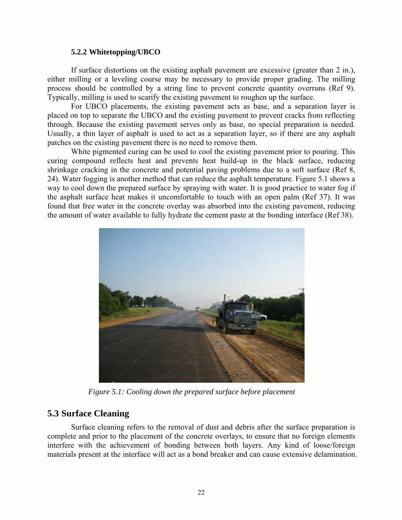
5.2.2 Whitetopping/UBCO If surface distortions on the existing asphalt pavement are excessive (greater than 2 in.),
either milling or a leveling course may be necessary to provide proper grading. The milling process should be controlled by a string line to prevent concrete quantity overruns (Ref 9). Typically, milling is used to scarify the existing pavement to roughen up the surface.
For UBCO placements, the existing pavement acts as base, and a separation layer is placed on top to separate the UBCO and the existing pavement to prevent cracks from reflecting through. Because the existing pavement serves only as base, no special preparation is needed. Usually, a thin layer of asphalt is used to act as a separation layer, so if there are any asphalt patches on the existing pavement there is no need to remove them.
White pigmented curing can be used to cool the existing pavement prior to pouring. This curing compound reflects heat and prevents heat build-up in the black surface, reducing shrinkage cracking in the concrete and potential paving problems due to a soft surface (Ref 8, 24). Water fogging is another method that can reduce the asphalt temperature. Figure 5.1 shows a way to cool down the prepared surface by spraying with water. It is good practice to water fog if the asphalt surface heat makes it uncomfortable to touch with an open palm (Ref 37). It was found that free water in the concrete overlay was absorbed into the existing pavement, reducing the amount of water available to fully hydrate the cement paste at the bonding interface (Ref 38).
Figure 5.1: Cooling down the prepared surface before placement
5.3 Surface Cleaning
Surface cleaning refers to the removal of dust and debris after the surface preparation is complete and prior to the placement of the concrete overlays, to ensure that no foreign elements interfere with the achievement of bonding between both layers. Any kind of loose/foreign materials present at the interface will act as a bond breaker and can cause extensive delamination.
23
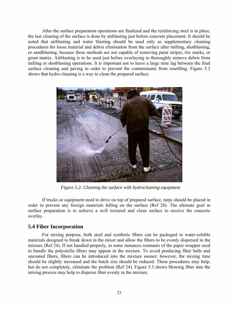
After the surface preparation operations are finalized and the reinforcing steel is in place, the last cleaning of the surface is done by airblasting just before concrete placement. It should be noted that airblasting and water blasting should be used only as supplementary cleaning procedures for loose material and debris elimination from the surface after milling, shotblasting, or sandblasting, because these methods are not capable of removing paint stripes, tire marks, or grout matrix. Airblasting is to be used just before overlaying to thoroughly remove debris from milling or shotblasting operations. It is important not to leave a large time lag between the final surface cleaning and paving in order to prevent the contaminants from resettling. Figure 5.2 shows that hydro cleaning is a way to clean the prepared surface.
Figure 5.2: Cleaning the surface with hydrocleaning equipment
If trucks or equipment need to drive on top of prepared surface, tarps should be placed in order to prevent any foreign materials falling on the surface (Ref 28). The ultimate goal in surface preparation is to achieve a well textured and clean surface to receive the concrete overlay.
5.4 Fiber Incorporation
For mixing purpose, both steel and synthetic fibers can be packaged in water-soluble materials designed to break down in the mixer and allow the fibers to be evenly dispersed in the mixture (Ref 24). If not handled properly, in some instances remnants of the paper wrapper used to bundle the polyolefin fibers may appear in the mixture. To avoid producing fiber balls and uncoated fibers, fibers can be introduced into the mixture sooner; however, the mixing time should be slightly increased and the batch size should be reduced. These procedures may help, but do not completely, eliminate the problem (Ref 24). Figure 5.3 shows blowing fiber into the mixing process may help to disperse fiber evenly in the mixture.
24
Figure 5.3: Blowing the fiber into the mixing truck
5.5 Placement
Below are general considerations for placement of concrete overlays.
To prevent water loss in concrete due to absorption by the existing pavement, the prepared surface ahead of the paving machine should be dampened with water to achieve saturated surface dry condition (Ref 11, 18, 39).
Tracking of dirt or debris ahead of paving machine should be prevented.
Bonding agents should not be used unless under special circumstances. With a properly prepared surface in SSD condition, a bonding agent, such as epoxy, is not required. If bonding agents are used improperly, they may act as bond breakers. (see section 3.8).
For BCOs, reinforcements can be directly placed on top of existing pavement—laboratory studies have shown that reinforcement placed at the interface develops the same bond as reinforcement placed in the middle of the overlay. Placement of the reinforcement at the interface also eliminates the risk of concrete honeycombing and poor consolidation beneath the steel (Ref 4).
The grading machine must be adjusted to achieve the required thickness of the concrete overlay.
The steel fibers at the surface of the pavement can become entangled with burlap and can be pulled out along with other fibers and coarse aggregates. An un-weighted carpet drag can be a substitution to provide a satisfactory interim surface finish on the pavement (Ref 23, 24).
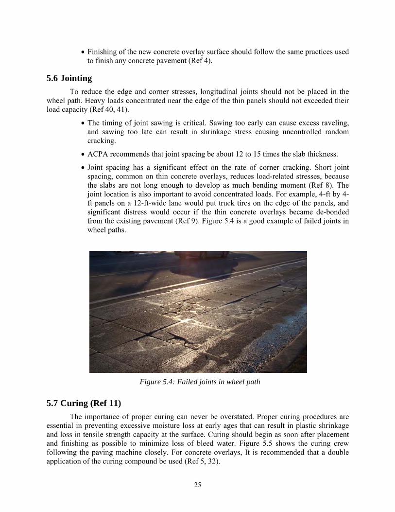
25
Finishing of the new concrete overlay surface should follow the same practices used to finish any concrete pavement (Ref 4).
5.6 Jointing
To reduce the edge and corner stresses, longitudinal joints should not be placed in the wheel path. Heavy loads concentrated near the edge of the thin panels should not exceeded their load capacity (Ref 40, 41).
The timing of joint sawing is critical. Sawing too early can cause excess raveling, and sawing too late can result in shrinkage stress causing uncontrolled random cracking.
ACPA recommends that joint spacing be about 12 to 15 times the slab thickness.
Joint spacing has a significant effect on the rate of corner cracking. Short joint spacing, common on thin concrete overlays, reduces load-related stresses, because the slabs are not long enough to develop as much bending moment (Ref 8). The joint location is also important to avoid concentrated loads. For example, 4-ft by 4-ft panels on a 12-ft-wide lane would put truck tires on the edge of the panels, and significant distress would occur if the thin concrete overlays became de-bonded from the existing pavement (Ref 9). Figure 5.4 is a good example of failed joints in wheel paths.
Figure 5.4: Failed joints in wheel path
5.7 Curing (Ref 11)
The importance of proper curing can never be overstated. Proper curing procedures are essential in preventing excessive moisture loss at early ages that can result in plastic shrinkage and loss in tensile strength capacity at the surface. Curing should begin as soon after placement and finishing as possible to minimize loss of bleed water. Figure 5.5 shows the curing crew following the paving machine closely. For concrete overlays, It is recommended that a double application of the curing compound be used (Ref 5, 32).
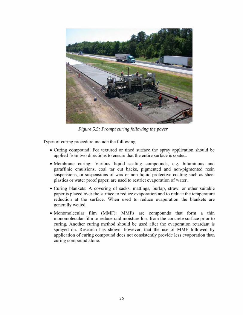
26
Figure 5.5: Prompt curing following the paver
Types of curing procedure include the following.
Curing compound: For textured or tined surface the spray application should be applied from two directions to ensure that the entire surface is coated.
Membrane curing: Various liquid sealing compounds, e.g. bituminous and paraffinic emulsions, coal tar cut backs, pigmented and non-pigmented resin suspensions, or suspensions of wax or non-liquid protective coating such as sheet plastics or water proof paper, are used to restrict evaporation of water.
Curing blankets: A covering of sacks, mattings, burlap, straw, or other suitable paper is placed over the surface to reduce evaporation and to reduce the temperature reduction at the surface. When used to reduce evaporation the blankets are generally wetted.
Monomolecular film (MMF): MMFs are compounds that form a thin monomolecular film to reduce raid moisture loss from the concrete surface prior to curing. Another curing method should be used after the evaporation retardant is sprayed on. Research has shown, however, that the use of MMF followed by application of curing compound does not consistently provide less evaporation than curing compound alone.
27
Chapter 6. Analysis of Forensic and Evaluation Studies in Texas
Forensic studies conducted on bonded concrete overlays (BCO) that had construction problems in Texas were reviewed. Understanding the causes of problems and knowing the appropriate recommendations will help to build better concrete overlays in the future.
6.1 Forensic Study of BCO on IH 10 in El Paso (Ref 45)
This bonded concrete overlay experienced delaminations in several areas soon after the construction. This report provides the causes of failure and recommendations for future expedited concrete overlays. Delamination of the overlay was due mainly to inadequate paste adhesion. Factors that led to delaminations include the following.
Low initial water content of the concrete mixture.
Loss of available water to substrate absorption.
Evaporation.
Withholding water from the mixture at batching
The following recommendations were made based on the forensics report.
Surface preparation: Shotblasted and/or hydrocleaned surface should be in saturated surface dry at placement of the overlay and should be air blasted within an hour before placement.
Evaporation rate: Placement only under acceptable environmental condition (typically evaporation rate of less than 0.2 lb/ft²/hr).
Opening to traffic: Must be at least 12 hours old and has attained splitting tensile strength of at least 500 psi.
Timing of Curing: Apply curing as soon as possible to prevent water loss due to evaporation.
6.2 Forensic Study of BCO on IH 30 in Fort Worth (Ref 46)
This project also experienced early delaminations after construction. After extensive forensics work, the cause of the problem was due to negligence in surface preparation in construction and was not a design failure. Debris was found in core samples that were extracted where the delaminations occurred. The conclusions to the problem are following.
Surface preparation and cleaning was done in a hurried way.
The debris was carried by surface water prior to concrete placement.
The debris accumulated just ahead of the paving machine.
The following recommendations were made based on the forensics report.
Monitor for severe weather conditions.
Proper surface preparation and cleaning.
28
Prompt application of curing compound.
Special curing, if necessary, when adverse weather condition warrants it.
6.3 Evaluation Study of First BCO in Texas
The first BCO project in Texas was implemented in 1983, on IH 610 (south loop). The project was an experimental BCO on a 1000-ft. continuously reinforced concrete pavement (CRCP) segment, built in July and August of 1983. It consisted of five 200-ft. test segments, with several combinations of reinforcement (no reinforcement, welded wire fabric, and steel fibers) and BCO thicknesses (2 and 3 in.), all constructed on the four eastbound lanes, between Cullen Boulevard and Calais Street. The surface was prepared by cold milling and sandblasting; portland cement grout was used as a bonding agent for the vast majority of the section.
The following lists the findings from the construction report (Ref 47):
Adding an overlay to an aged pavement improves the structural quality of the pavement as measured by the reduction in deflection both at cracks and at mid-span positions.
Overlaying on a dry surface results in better bond strength at the interface than overlaying on a wet surface. Specifically, overlaying when the surface is wet results in the weakest interface bond strength. Under this condition, it is advisable to apply a grouting agent or to dry the surface before overlaying. If the surface is dry, there is no need for using a grouting agent.
Roughening the surface as by milling or scarifying helps produce a better bond.
The effect of positioning overlay reinforcements on interface bond strength is insignificant. Hence reinforcing bars can be placed on the original surface in the interests of cost saving.
Fiber-reinforced overlays are a good alternative to plain or bar-reinforced concrete overlays.
The following lists the findings from an evaluation report after 2 years of service (Ref 43).
In BCO construction, a mixture of water, cement, and plasticizer is an adequate bonding agent.
Two to three years after BCO placement, no significant debonding seems to have occurred.
The fiber sections proved to be far superior in their ability to control longitudinal and transverse cracking.
After almost two years of BCO service virtually none of the cracks showed evidence of spalling.
The five test sections on South Lop 610 have been monitored for approximately two years. During this period, satisfactory performance has been noted on most of the pavement response variables. However, the long-term performance still needs to be established.
29
A sounding survey conducted in 1990 on this section revealed some minimal delamination of the overlay (Ref 5). Condition surveys conducted in 1996 showed few distresses on the section and no major performance problems (Ref 48). The success of this first experience led TxDOT to implement a second BCO project.
6.4 Evaluation Study of Second BCO in Texas
The second BCO was implemented on the north side of IH 610. The section in question consisted of a 3.5-mile stretch on the northwest part of the loop, between East T.C. Jester Boulevard and IH 45. Originally built in the late 1950s, the 8-in. slab of CRCP on a 6-in.-thick cement stabilized subbase was overlaid with a 4-in.-thick BCO in 1986 (Ref 30). This overlay project experimented with several variables, including reinforcement, coarse aggregates, bonding agents and existing pavement conditions (various levels of distress).
Within the project limits, ten test subsections were identified, with lengths ranging from 400 to 600 ft, each including different combinations of the aforementioned variables. During and after construction, some delamination took place between the BCO and the original pavement. It was found that most the delaminations occurred within the first 24 hours after placement due to the presence of adverse environmental conditions during overlay placement, i.e., high evaporation rates and high daily temperature differentials, and always occurred at a joint, crack or edge.
The following lists the findings from the evaluation report (Ref 47).
Bonded concrete overlays significantly reduce the pavement deflection. The deflection reduction magnitudes indicate the slab performed monolithically. The section of CRC with siliceous river gravel reduced deflection the most as expected due to its higher modulus of elasticity.
The existing pavement conditions did not affect the overlay pavement performance as long as most of the existing distresses were repaired before the overlay was placed.
Roughening the surface by milling or scarifying helps produce a better bond.
Overall, there was a significant decrease in the amount of all types of distress. The section of CRCP with limestone had the least number of transverse cracks, and the siliceous river gravel and fiber-reinforced sections were second and third, respectively. Spalling and punchouts did not exist on any of the test sections.
Even though in some segments the delamination was extensive, it did not continue to deteriorate over time and did not appear to significantly affect performance (Ref 49). Relatively recent condition surveys conducted on this segment in November 2000 and June 2006 revealed that, in spite of the heavy traffic, after 20 years of service, the BCO was still in excellent shape, presenting a minimal number of distresses (Ref 18, 50).
6.5 Evaluation Study of Third BCO in Texas
The third BCO rehabilitation in Texas was also implemented on the IH 610 Loop in Houston. In this case, the rehabilitated section was located on the southeast quadrant of the urban interstate loop. Important lessons learned in the IH 610 North project were applied in the construction of this rehabilitation, such as limiting the evaporation rate during construction to
30
less than 0.2 lb/ft²/hr and allowing concrete placement only when the temperature differential expected between placement and the following day is less than 25°F, as adverse environmental conditions surpassing these limits were identified as the primary triggers of the IH 610 North BCO delaminations.
The 8-in.-thick CRCP section is about 4 miles long, and it included the aforementioned BCO built in 1983. The approximate project limits are from just east of SH 288, to just west of Telephone Rd. (Ref 30). This project started in 1989 and was completed in 1990. It consisted of a 4-in.-thick BCO placed on 112 lane miles. The reinforcement was wire mesh and the coarse aggregate was limestone. Portland cement grout was used as the bonding agent (Ref 5, 30).
The BCO included ten experimental sections, each 400 ft long and four lanes wide, in which several combinations of bonding agents, reinforcements, and surface treatments were implemented (Ref 36). Substantial early delaminations occurred in the sections where a latex modified portland cement grout was used as bonding agent, which prompted the removal of the overlay shortly after construction. The reason for the delamination was that the grout was being sprayed too far ahead of the paving machine, allowing much of the grout to dry. Before the concrete overlay was placed the contractor applied new grout over the dried grout, in which the solid latex at the interface behaved as a bond-breaking layer. The BCO was replaced within 30 days, after the sections received the same treatment as the control sections (cold milling and PC grout). Aside from dismissing the use of latex as a bonding agent, another important lesson learned is that the bond failures were induced at relatively low stresses (under 50 psi), while the overlay is still in its early age. The experiment results also emphasized the importance of good surface preparation.
31
Chapter 7. Review of Other State and RILEM Reports
Various overlay studies that were performed outside of Texas were reviewed in order to broaden the current knowledge database. This section includes summarized experiences from other states and a review of RILEM report done by Dr. David W. Fowler and Dr. Manuel Trevino.
7.1 Reports from Other States
Unlike Texas, other states have numerous experiences in unbonded concrete overlays, other types of overlays, and fiber usage. Most of UBCO knowledge of this deliverable came from reviewing their reports.
7.1.1 Virginia (Ref 51)
Three fiber-reinforced concrete pavements placed in Virginia in June and July 1995 are being evaluated to establish the relationship between the properties of fiber-reinforced concrete overlay and field performance. The concretes used in these projects contained steel (hooked-end) (0.4 and 0.6% by volume), fibrillated polypropylene (0.2% by volume), monofilament polypropylene (0.1 and 0.3% by volume), and polyolefin (1.3 and 1.6% by volume). The properties of the concretes in these overlay projects and in the concretes prepared for this study were similar, and the laboratory testing of field concretes yielded results similar to the ones obtained in this study.
After a preliminary evaluation of the overlays after construction and at one year, it appears that the fiber-reinforced concrete overlay in the field is functioning as expected, controlling crack propagation and widening. In one project, the concrete shows extensive cracking toward the end sections, which contained concretes with and without fibers. The cracks have widened over the year. Indications are that the widths of the cracks in areas with fibers were less than those in the control section. Cracks in areas with steel and polyolefin fibers had the narrowest widths.
Based on the research, following conclusions were made.
The use of fibers reduces the workability of concrete. However, with the addition of high range water reducers, workability similar to that of concretes without fibers is achieved.
Although the ultimate splitting tensile strength, compressive strength, and first crack strength are higher in most fiber-reinforced concrete overlays, only a few demonstrate increased strength after adjustments for air content.
The impact resistance of concretes is greatly improved with increases in fiber volume and length. Concretes with polyolefin and steel fibers have the highest impact resistance.
The toughness of concretes improves with increases in fiber volume. The highest toughness values are achieved with steel fibers, followed by polyolefin and then polypropylene fibers.
32
Field results are in accordance with laboratory results. After 1 year, crack propagation and widening appear to be controlled in fiber-reinforced concrete overlays in the field.
7.1.2 Missouri (Ref 23)
An UBCO was designed and built on 1-29 in Atchison County in northwestern Missouri. The location of the project is between Route A and US 136 in the southbound lanes. Eight test sections were established in the UBCO. Three of the test sections were reinforced with steel fibers, three of the test sections were reinforced with polyolefin fibers, and two of the test sections were non-reinforced concrete overlay. There were fiber-reinforced test sections 9-in., 6-in., and 5-in.-thick for each type of fiber reinforcement. Transverse joint spacing varied in the fiber-reinforced sections from 15 ft. to 200 ft. The two non reinforced concrete overlay test sections were 9-in. and 11-in. and all transverse joints were spaced 15 ft.
The concrete overlay was designed as an UBCO, using a 1-in. bituminous interlayer, to decrease the reflective cracking of joints and cracks from the existing pavement into the new overlay. The following conclusions were made.
In this study, the use of polyolefin fibers mixed at 25 lb/yd³ in concrete lead to a significant decrease in compressive and flexural strength at 28 days when compared to a non-reinforced concrete of similar mixture proportions. The use of steel fibers in concrete had little effect on the compressive and flexural strength at 28 days.
The use of a burlap drag to provide the interim surface finish for the fiber-reinforced UBCO resulted in a poor finish because the fibers became entangled in the burlap leading to other fibers and coarse aggregate being pulled from the surface of the pavement. An unweighted carpet drag provided an acceptable interim finish.
Both the steel fibers and the polyolefin fibers exhibited some non-uniform distribution of fibers in the concrete. The polyolefin fibers appeared more susceptible to mixing inconsistencies such as fiber balling and the presence of uncoated fibers in the mixture than the steel fibers.
Diamond grinding of the UBCO provided a smooth profile with no detrimental effect on the friction characteristics of the pavement.
Based on data from one year of service, the 1-in.-thick asphalt interlayer appears adequate to prevent major reflective cracking on this project.
The steel fiber-reinforced sections of the UBCO exhibited more transverse cracking than the polyolefin fiber-reinforced sections.
Based on the one-year survey data, the 6-in. polyolefin fiber-reinforced section has performed nearly as well, in terms of crack development, as the 9-in. polyolefin fiber-reinforced section.
To date, the steel fibers have restricted the opening of cracks more than the polyolefin fibers.

33
The thickness of the concrete overlay greatly impacted the development of transverse cracks in the overlay. In general, the thinner sections developed more transverse cracking than thicker sections.
The small coverage of concrete over the dowel bars at transverse joints in the 5-in. steel fiber-reinforced sections contributed to spalling over those dowel bars.
The polyolefin fiber-reinforced sections with transverse joint spacing of thirty feet exhibited nearly no transverse cracking based on the one-year survey. Also, the 9-in. polyolefin fiber-reinforced section with 60-ft panels showed very little transverse cracking.
7.1.3 Louisiana (Ref 29)
A BCO was constructed on an 8-in.-thick 4-lane section of Interstate 10 CRCP, located in the southern part of East Baton Rouge. The entire construction project length was 5.2 miles located between Siegen Lane in Baton Rouge and LA 42 (Highland Road). The project objectives were to provide an overlay with a high probability for long term success by incorporating design variables to increase the probability of long term performance. The variables included the following.
Concrete reinforced with steel fibers and a high cement factor.
A clean, textured bonding surface.
Edge bond reinforcement which pinned the overlay along slab edges.
Full-width, tied concrete shoulders.
Before the placement of the concrete overlay, severe edge failures and any longitudinal cracks were patched. The contractor successfully used shotblasting equipment to achieve the required surface texture. Grout slurry (seven gallons of water to one bag of cement), in the effort to increase the bonding, was applied as a thin, even coat onto the cleaned dry concrete surface just ahead of the paver.
Mixture design consisted of a minimum of 7.5 sacks of cement per cubic yard with a maximum w/c of 0.40. The steel fibers were added in with the aggregates via a conveyor belt and mixed using 85 to 90 lb of fibers per cubic yard.
An artificial turf drag was selected as the drag finish but was discontinued due to fibers catching on the material. A burlap drag was then substituted with no apparent problems. Due to the thinness of the concrete overlay, a white pigmented curing compound was applied at one and one half times the normal application rate to enhance curing process.
The 4-in. BCO has been successfully bonded to a 16-year-old CRCP which had carried twice its design load. After three years of service, 35% of the transverse cracks had reflected through and held tight by internal steel fiber reinforcement and edge reinforcement. A combination of water-cement grout and a clean, textured surface provided excellent bond between fresh and hardened concrete. Slab deflections at the edge of the pavement were reduced an estimated total of 60%. This major reduction in deflection reflects a significant enhancement in load carrying capacity.
34
7.1.4 Illinois (Ref 28)
A section of Interstate 80 near the Illinois–Iowa border was chosen for the experiment. In December 1993 and January 1994, the Bureau of Materials and Physical Research (BMPR) conducted a laboratory experiment using microsilica and bonding agents. The investigation examined two variables.
The differences in compressive strengths of mixture designs using various percentages of microsilica.
The differences in bond strengths using various bonding agents.
Because the surface of the existing concrete pavement had large areas of bituminous materials, they were cold milled and, then, the surface was shot blasted. Sandblasting equipment was used to prepare the areas that were difficult to maneuver the shotblasting equipment. After the construction and an evaluation, the following conclusions were made.
Surface preparation for the BCO is crucial to obtaining a good overlay.
Bond strength of the overlay did not vary significant either with or without grout as a bonding agent.
Placing the grout was cumbersome and slowed down the paving process.
Addition of microsilica did not improve the strength of the mixture greatly.
Based on the experience, the following recommendations were made.
Tarps should be required if trucks or other equipment will be driving on the cleaned surface.
The use of grout should be eliminated, because the bond strength was not increased significantly and to keep from slowing down the paving process.
The addition of micro silica to the mixture could be eliminated if the permeability of chloride is not drastically affected.
Shot blasting fines should not be piled along the side of the road.
Shotblasting/sandblasting should be kept near the paving operation.
7.1.5 Iowa (Ref 52)
The Iowa Highway 13 project is a stretch of roadway that extends 9.6 miles from Manchester, Iowa to Iowa Highway 3 in Delaware County. This portion of Iowa 13 is a two-lane rural roadway, 24 ft wide. It has a narrow granular-surfaced shoulder and a rolling longitudinal grade with minimum ditch depths approximately 3 to 6 ft below the top of the pavement. The following conclusions were made.
Concrete overlay depths of 3.5 in. or greater can be built without the use of fiber inclusion.
Adding fibers to concrete overlay depths of 4 in. or less will provide insurance against loss of materials in the event of an individual slab loss-of-support and multiple cracking.
35
Structural fibers can provide an opportunity for larger slab sizes without loss of load transfer or increased cracking rates in overlays of 4.5-in. or less.
Minimal scarification of the base asphaltic concrete surface is shown to be the most efficient way to control concrete overlay quantities, assure proper cross slope, and minimize overlay thickness design while placing additional concrete in the rutted areas of existing surface.
7.2 Review of RILEM Report
The latest Reunion Internationale des Laboratoires et Experts des Materiaux (RILEM) draft report on bonded concrete overlays was the source of most of the information for this particular task. Dr. David W. Fowler and Dr. Manuel Trevino were asked to author several chapters in the report, which provides great insight on U.S. and European experience using BCOs. Many reports from other DOTs and international groups also were researched for this task.
7.2.1 Materials Consideration
When designing the concrete mixture, the cement content must be high enough to ensure that the available paste will promote sufficient bonding. However, the cement content must be low enough to minimize cost and heat of hydration. Therefore, there must be a balance. Using fly ash may reduce heat of hydration and cost while durability and ultimate strength may be increased.
Generally, a w/cm ratio of 0.40 will provide good durability and strength. One specification requires a w/cm ratio of 0.40 for normal concrete overlay and 0.32 for dense overlay concrete.
Proper aggregate selection for workability with adequate durability is important. Improved gradation may reduce paste requirements and may be helpful when steel fibers are used. Aggregates used in the concrete overlay should have lower thermal coefficients that can normally be obtained by using limestone materials.
Air entrainment and admixtures used to help workability and improve freezing and thawing resistance. When fly ash is incorporated into the mixture, greater dosages of air entraining may be required. Also, high range water reducers are often specified based on trial batches. Retarders can be used in hot weather to preserve workability.
Reinforcements include tie bars, welded mats, and the mixture of steel and synthetic fibers. Steel fibers are used to control cracks and to minimize drying shrinkage cracking. Normal steel fiber contents for steel fiber-reinforced concrete are normally in the range of 1 to 2% by volume. The type and dimensions of the fiber will dictate the amount of fibers required. Synthetic fibers should be used at a minimum of 0.25% by volume; however, significant benefits have been obtained by using up to 1% volume.
7.2.2 Construction Procedures
Direct Reinforcement Placement: Research has shown that the reinforcing placed on the substrate of a 3-in.-thick slab with a 3-in. concrete overlay cast on the surface will achieve the same pull-out bond strength as reinforcing placed at mid-depth of a 6-in.-thick slab. Placing the reinforcements directly on the substrate saves construction time and labor.
36
Surface Preparation: Surface must be adequately cleaned, preferably by shot blasting and using steel shot to a moderate roughness. The surface must be kept clean prior to placement of concrete. Bonding agents are not necessary and should be avoided because they provide an additional step that can cause failure, e.g., a bonding agent that is allowed to cure prior to concrete placement, becoming a bond breaker (Ref 53).
Weather Conditions: Weather conditions, during and after the construction can be critical to the quality of overlay. Hot and dry climates can cause a detrimental effect due to excessive evaporation of water from the concrete, which in turn causes plastic shrinkage cracking. There are published monographs that can help to estimate evaporation rate depending on the weather and materials condition. The evaporation should be monitored throughout the construction using a weather station. When threshold value of evaporation rate is approached, appropriate action should be taken to discontinue the placement of the overlay or provide measures to reduce evaporation rate.
7.2.3 Curing
The importance of proper curing can never be overstated. Proper curing procedures are essential in preventing excessive moisture loss at early ages that can result in plastic shrinkage and loss in tensile strength capacity at the surface. Curing should begin as soon after placement and finishing as possible to minimize loss of bleed water.
Types of curing include the following.
Curing compound: For textured or tined surface the spray application should be applied from two directions to ensure that the entire surface is coated.
Membrane curing: Various liquid sealing compounds, e.g. bituminous and paraffinic emulsions, coal tar cut backs, pigmented and non-pigmented resin suspensions, or suspensions of wax or non-liquid protective coating such as sheet plastics or water proof paper, are used to restrict evaporation of water.
Curing blankets: A covering of sacks, mattings, burlap, straw, or other suitable paper is placed over the surface to reduce evaporation and to reduce the temperature reduction at the surface. When used to reduce evaporation the blankets are generally wetted.
Monomolecular film: MMFs are compounds that form a thin monomolecular film to reduce raid moisture loss from the concrete surface prior to curing. Another curing method should be used after the evaporation retardant is sprayed on. Research has shown, however, that the use of MMF followed by application of curing compound does not consistently provide less evaporation than curing compound alone.

37
Chapter 8. Condition/Evaluation Surveys in Texas
A number of sites were visited throughout Texas to perform condition/evaluation surveys. The following sections summarize the results of these surveys.
8.1 Houston—SH 146 and SH 225
On June 8, 2010, a field trip was conducted to visit two bonded concrete overlay projects in the Houston area. The purpose of the trip was to perform visual condition surveys on the BCOs on SH 146 and SH 225, as part of Task 2 of the study, Condition Survey and Evaluation of Existing Concrete Overlays in Texas. The research in this task entails the review and visit of existing concrete overlays in the state to evaluate their performance.
Unfortunately, only one of the overlay surveys could be done as planned: just at the time of setting up for the survey, it was found that the 4.25-mi-long BCO segment on SH 225, from the IH 610 Loop to Redbluff, has been resurfaced with asphalt, making it impossible to perform the survey on this section.
The survey on SH 146 was conducted. The BCO is located in Harris County in Baytown, and its limits are from the Chambers County line to North Main Street, for an approximate length of 4.5 mi.
The overlay consists of a 3-in.-thick BCO on top of the existing 11-in.-thick CRCP. This BCO was designed in 1998, and it was constructed in the early 2000s.
8.1.1 SH 146 Survey
The survey consisted of a visual inspection of the outside lane of the BCO, observing the cracks and distress, including photographs. Because the road was open for traffic, it was not possible to conduct this survey in more detail. The survey was conducted while driving at a very low speed in the outside traffic lane, while a cushion truck and a shadow vehicle, provided by the district, moved along behind the survey vehicle for protection. During part of the survey, there was rain, which made it hard to see the pavement at times. The rain was particularly intense during the surveying of the southbound lanes; therefore, the level of detail of this part of the survey was not optimal. The survey started with the northbound direction, from North Main Street to the Chambers County line, and then the southbound direction followed.
The distresses found consist mainly of punchouts and minor spalls. There were a number of punchouts at the south end of the section in the southbound lanes, where the pavement showed a limited number of cracks, but some distresses had been repaired and were failing again. There were also some sections in very good condition without many cracks or distresses.
Table 8.1 shows the results of the northbound direction, and Table 8.2 presents the southbound direction.
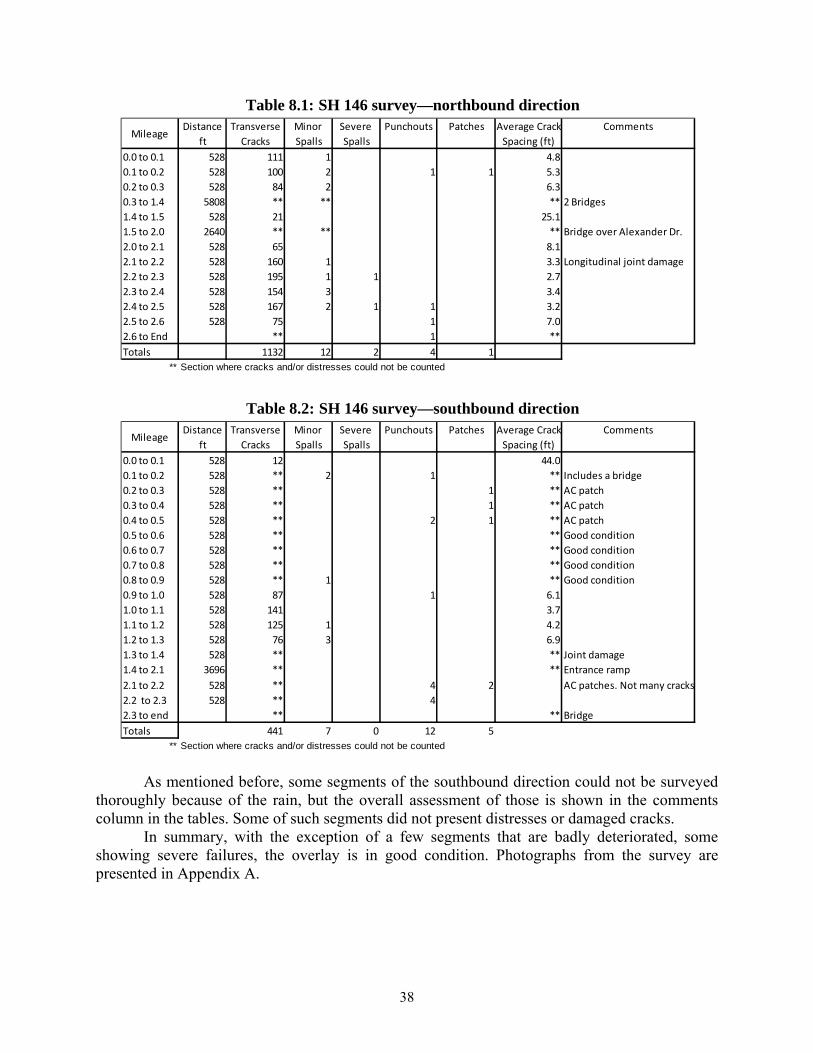
38
Table 8.1: SH 146 survey—northbound direction
Table 8.2: SH 146 survey—southbound direction
As mentioned before, some segments of the southbound direction could not be surveyed
thoroughly because of the rain, but the overall assessment of those is shown in the comments column in the tables. Some of such segments did not present distresses or damaged cracks.
In summary, with the exception of a few segments that are badly deteriorated, some showing severe failures, the overlay is in good condition. Photographs from the survey are presented in Appendix A.
Distance Transverse Minor Severe Punchouts Patches Average Crack
ft Cracks Spalls Spalls Spacing (ft)
0.0 to 0.1 528 111 1 4.8
0.1 to 0.2 528 100 2 1 1 5.3
0.2 to 0.3 528 84 2 6.3
0.3 to 1.4 5808 ** ** ** 2 Bridges
1.4 to 1.5 528 21 25.1
1.5 to 2.0 2640 ** ** ** Bridge over Alexander Dr.
2.0 to 2.1 528 65 8.1
2.1 to 2.2 528 160 1 3.3 Longitudinal joint damage
2.2 to 2.3 528 195 1 1 2.7
2.3 to 2.4 528 154 3 3.4
2.4 to 2.5 528 167 2 1 1 3.2
2.5 to 2.6 528 75 1 7.0
2.6 to End ** 1 **
Totals 1132 12 2 4 1
** Section where cracks and/or distresses could not be counted
MileageComments
Distance Transverse Minor Severe Punchouts Patches Average Crack
ft Cracks Spalls Spalls Spacing (ft)
0.0 to 0.1 528 12 44.0
0.1 to 0.2 528 ** 2 1 ** Includes a bridge
0.2 to 0.3 528 ** 1 ** AC patch
0.3 to 0.4 528 ** 1 ** AC patch
0.4 to 0.5 528 ** 2 1 ** AC patch
0.5 to 0.6 528 ** ** Good condition
0.6 to 0.7 528 ** ** Good condition
0.7 to 0.8 528 ** ** Good condition
0.8 to 0.9 528 ** 1 ** Good condition
0.9 to 1.0 528 87 1 6.1
1.0 to 1.1 528 141 3.7
1.1 to 1.2 528 125 1 4.2
1.2 to 1.3 528 76 3 6.9
1.3 to 1.4 528 ** ** Joint damage
1.4 to 2.1 3696 ** ** Entrance ramp
2.1 to 2.2 528 ** 4 2 AC patches. Not many cracks
2.2 to 2.3 528 ** 4
2.3 to end ** ** Bridge
Totals 441 7 0 12 5
** Section where cracks and/or distresses could not be counted
MileageComments
39
8.2 Houston—Beltway 8
On May 19, 2010, a field trip was conducted to visit the BCO project on Beltway 8 in Houston. The pavement in question is a 2-in.-thick BCO with fibers constructed in 1996, on Beltway 8, the urban outer loop that surrounds IH 610 in Houston. The project section, approximately 5.3 miles long, is located between Greenspoint Drive, just east of IH 45, and Aldine Westfield, near Houston Intercontinental Airport. The original 13-in.-thick CRCP structure, built in 1984, experienced a severe spalling problem just a few years after construction. By 1995, when the overlay rehabilitation project was undertaken, the CRCP section was in poor condition. A CTR investigation on that pavement concluded that the reason for the spalling was high evaporation rates and high daily temperature differentials that occurred during the construction time. Deflection tests and core samples were extracted at the time to evaluate the structural integrity of the pavement. The tests showed that the spalling problem was only superficial, and it did not significantly affect the load-carrying capacity of the pavement, making it a good candidate for BCO rehabilitation. As a result of that study, a 2-in.-thick BCO reinforced with steel fibers was designed and constructed in 1996.
8.2.1 Condition Survey
The survey consisted of a visual inspection of the outside lane of the BCO, observing the cracks and distress, including photographs. Because the road was open for traffic, it was not possible to walk the section to conduct this survey in more detail. The survey was performed while driving at a very low speed on the outside traffic lane, while a cushion truck and a shadow vehicle, provided by the district, moved along behind the surveyor vehicle for protection. The survey started with the westbound direction, from Aldine Westfield, and proceeded to Greenspoint Dr., followed by the eastbound direction.
The transverse cracks appeared to be in good shape, were not wide, and the spacing seemed to be adequate. The few distresses found consisted mainly of minor spalls. There was a very long longitudinal crack that extended for a few tenths of a mile on the westbound outside lane. However, this crack was narrow and despite its length, it did not seem to be associated to additional distresses. The eastbound direction also presented asphalt some patches, but mainly concrete patches. There was a particularly long portland cement concrete (PCC) patch that extended for about 45 ft. on the eastbound inside lane.
Table 8.3 summarizes the results of the westbound direction, and Table 8.4 presents the eastbound direction results.
In summary, the overlay was in excellent condition. The few spalls that were present, mainly in the westbound direction, were all minor. Even though there are a handful of distresses, none of them appeared to be severe. No punchouts were observed. Photographs from the survey are presented in Appendix B.
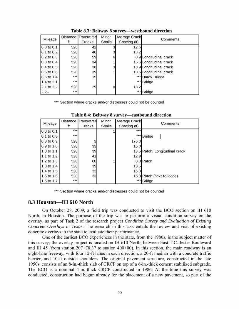
40
Table 8.3: Beltway 8 survey—westbound direction
Table 8.4: Beltway 8 survey—eastbound direction
8.3 Houston—IH 610 North
On October 28, 2009, a field trip was conducted to visit the BCO section on IH 610 North, in Houston. The purpose of the trip was to perform a visual condition survey on the overlay, as part of Task 2 of the research project Condition Survey and Evaluation of Existing Concrete Overlays in Texas. The research in this task entails the review and visit of existing concrete overlays in the state to evaluate their performance.
One of the earliest BCO experiences in the state, from the 1980s, is the subject matter of this survey; the overlay project is located on IH 610 North, between East T.C. Jester Boulevard and IH 45 (from station 207+78.37 to station 400+00). In this section, the main roadway is an eight-lane freeway, with four 12-ft lanes in each direction, a 20-ft median with a concrete traffic barrier, and 10-ft outside shoulders. The original pavement structure, constructed in the late 1950s, consists of an 8-in.-thick slab of CRCP on top of a 6-in.-thick cement stabilized subgrade. The BCO is a nominal 4-in.-thick CRCP constructed in 1986. At the time this survey was conducted, construction had begun already for the placement of a new pavement, so part of the
Distance Transverse Minor Average Crackft Cracks Spalls Spacing (ft)
0.0 to 0.1 528 42 3 12.60.1 to 0.2 528 40 3 13.20.2 to 0.3 528 59 6 8.9 Longitudinal crack0.3 to 0.4 528 34 1 15.5 Longitudinal crack0.4 to 0.5 528 38 3 13.9 Longitudinal crack0.5 to 0.6 528 39 1 13.5 Longitudinal crack0.6 to 1.4 *** 15 *** Hardy Bridge1.4 to 2.1 *** *** Bridge2.1 to 2.2 528 29 0 18.22.2-- *** *** Bridge
*** Section where cracks and/or distresses could not be counted
Mileage Comments
Distance Transverse Minor Average Crackft Cracks Spalls Spacing (ft)
0.0 to 0.1 *** 1 ***0.1 to 0.8 *** *** Bridge0.8 to 0.9 528 3 176.00.9 to 1.0 528 33 16.01.0 to 1.1 528 39 13.5 Patch, Longitudinal crack1.1 to 1.2 528 41 12.91.2 to 1.3 528 60 1 8.8 Patch1.3 to 1.4 528 39 13.51.4 to 1.5 528 33 16.01.5 to 1.6 528 33 16.0 Patch (next to loops)1.6 to 1.7 *** *** Bridge
*** Section where cracks and/or distresses could not be counted
Mileage Comments
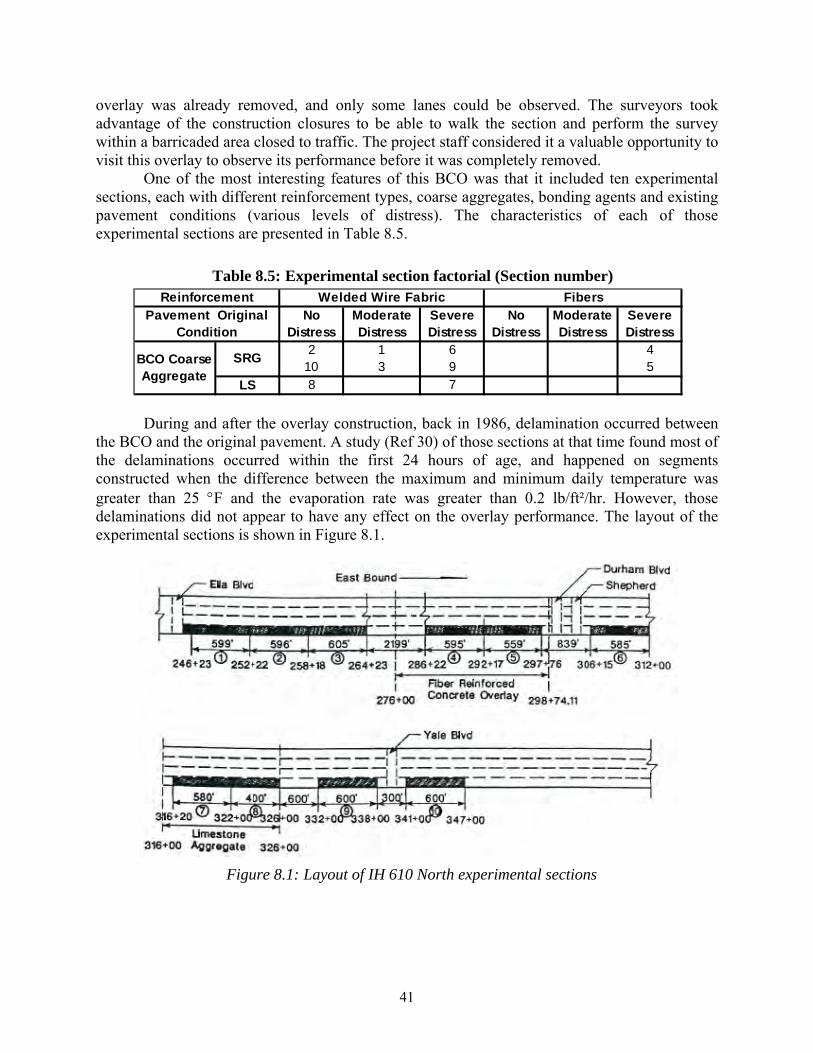
41
overlay was already removed, and only some lanes could be observed. The surveyors took advantage of the construction closures to be able to walk the section and perform the survey within a barricaded area closed to traffic. The project staff considered it a valuable opportunity to visit this overlay to observe its performance before it was completely removed.
One of the most interesting features of this BCO was that it included ten experimental sections, each with different reinforcement types, coarse aggregates, bonding agents and existing pavement conditions (various levels of distress). The characteristics of each of those experimental sections are presented in Table 8.5.
Table 8.5: Experimental section factorial (Section number)
During and after the overlay construction, back in 1986, delamination occurred between the BCO and the original pavement. A study (Ref 30) of those sections at that time found most of the delaminations occurred within the first 24 hours of age, and happened on segments constructed when the difference between the maximum and minimum daily temperature was greater than 25 F and the evaporation rate was greater than 0.2 lb/ft²/hr. However, those delaminations did not appear to have any effect on the overlay performance. The layout of the experimental sections is shown in Figure 8.1.
Figure 8.1: Layout of IH 610 North experimental sections
No Distress
Moderate Distress
Severe Distress
No Distress
Moderate Distress
Severe Distress
2 1 6 410 3 9 5
LS 8 7
Reinforcement Welded Wire Fabric FibersPavement Original
Condition
BCO Coarse Aggregate
SRG
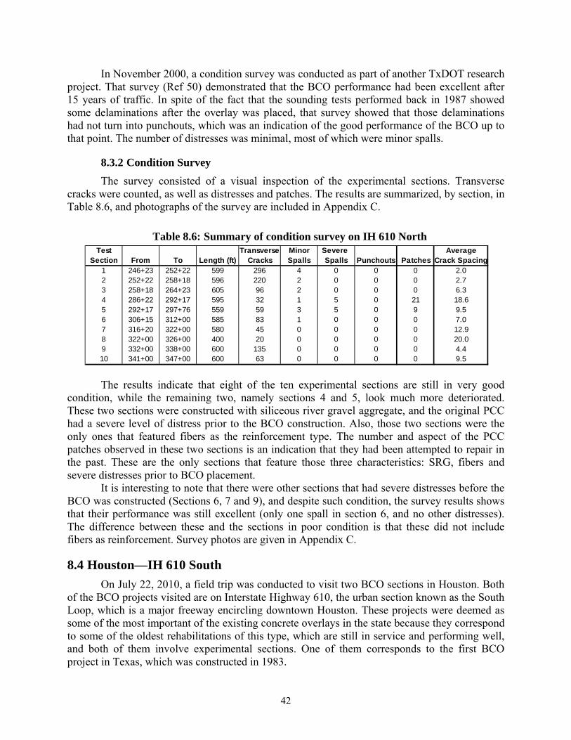
42
In November 2000, a condition survey was conducted as part of another TxDOT research project. That survey (Ref 50) demonstrated that the BCO performance had been excellent after 15 years of traffic. In spite of the fact that the sounding tests performed back in 1987 showed some delaminations after the overlay was placed, that survey showed that those delaminations had not turn into punchouts, which was an indication of the good performance of the BCO up to that point. The number of distresses was minimal, most of which were minor spalls.
8.3.2 Condition Survey
The survey consisted of a visual inspection of the experimental sections. Transverse cracks were counted, as well as distresses and patches. The results are summarized, by section, in Table 8.6, and photographs of the survey are included in Appendix C.
Table 8.6: Summary of condition survey on IH 610 North
The results indicate that eight of the ten experimental sections are still in very good condition, while the remaining two, namely sections 4 and 5, look much more deteriorated. These two sections were constructed with siliceous river gravel aggregate, and the original PCC had a severe level of distress prior to the BCO construction. Also, those two sections were the only ones that featured fibers as the reinforcement type. The number and aspect of the PCC patches observed in these two sections is an indication that they had been attempted to repair in the past. These are the only sections that feature those three characteristics: SRG, fibers and severe distresses prior to BCO placement.
It is interesting to note that there were other sections that had severe distresses before the BCO was constructed (Sections 6, 7 and 9), and despite such condition, the survey results shows that their performance was still excellent (only one spall in section 6, and no other distresses). The difference between these and the sections in poor condition is that these did not include fibers as reinforcement. Survey photos are given in Appendix C.
8.4 Houston—IH 610 South
On July 22, 2010, a field trip was conducted to visit two BCO sections in Houston. Both of the BCO projects visited are on Interstate Highway 610, the urban section known as the South Loop, which is a major freeway encircling downtown Houston. These projects were deemed as some of the most important of the existing concrete overlays in the state because they correspond to some of the oldest rehabilitations of this type, which are still in service and performing well, and both of them involve experimental sections. One of them corresponds to the first BCO project in Texas, which was constructed in 1983.
Test Transverse Minor Severe AverageSection From To Length (ft) Cracks Spalls Spalls Punchouts Patches Crack Spacing
1 246+23 252+22 599 296 4 0 0 0 2.02 252+22 258+18 596 220 2 0 0 0 2.73 258+18 264+23 605 96 2 0 0 0 6.34 286+22 292+17 595 32 1 5 0 21 18.65 292+17 297+76 559 59 3 5 0 9 9.56 306+15 312+00 585 83 1 0 0 0 7.07 316+20 322+00 580 45 0 0 0 0 12.98 322+00 326+00 400 20 0 0 0 0 20.09 332+00 338+00 600 135 0 0 0 0 4.410 341+00 347+00 600 63 0 0 0 0 9.5
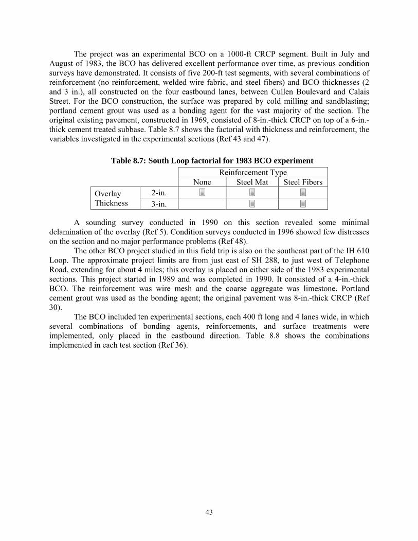
43
The project was an experimental BCO on a 1000-ft CRCP segment. Built in July and August of 1983, the BCO has delivered excellent performance over time, as previous condition surveys have demonstrated. It consists of five 200-ft test segments, with several combinations of reinforcement (no reinforcement, welded wire fabric, and steel fibers) and BCO thicknesses (2 and 3 in.), all constructed on the four eastbound lanes, between Cullen Boulevard and Calais Street. For the BCO construction, the surface was prepared by cold milling and sandblasting; portland cement grout was used as a bonding agent for the vast majority of the section. The original existing pavement, constructed in 1969, consisted of 8-in.-thick CRCP on top of a 6-in.-thick cement treated subbase. Table 8.7 shows the factorial with thickness and reinforcement, the variables investigated in the experimental sections (Ref 43 and 47).
Table 8.7: South Loop factorial for 1983 BCO experiment
Reinforcement Type None Steel Mat Steel Fibers
Overlay Thickness
2-in. 3-in.
A sounding survey conducted in 1990 on this section revealed some minimal
delamination of the overlay (Ref 5). Condition surveys conducted in 1996 showed few distresses on the section and no major performance problems (Ref 48).
The other BCO project studied in this field trip is also on the southeast part of the IH 610 Loop. The approximate project limits are from just east of SH 288, to just west of Telephone Road, extending for about 4 miles; this overlay is placed on either side of the 1983 experimental sections. This project started in 1989 and was completed in 1990. It consisted of a 4-in.-thick BCO. The reinforcement was wire mesh and the coarse aggregate was limestone. Portland cement grout was used as the bonding agent; the original pavement was 8-in.-thick CRCP (Ref 30).
The BCO included ten experimental sections, each 400 ft long and 4 lanes wide, in which several combinations of bonding agents, reinforcements, and surface treatments were implemented, only placed in the eastbound direction. Table 8.8 shows the combinations implemented in each test section (Ref 36).
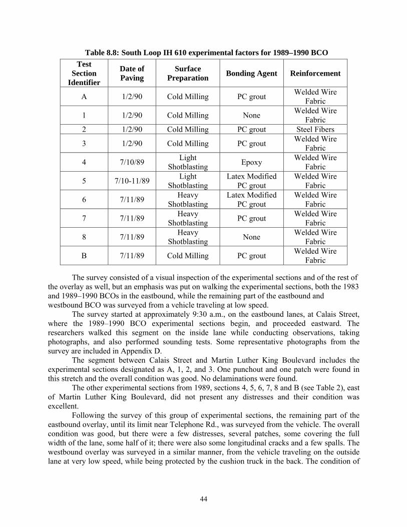
44
Table 8.8: South Loop IH 610 experimental factors for 1989–1990 BCO
Test Section
Identifier
Date of Paving
Surface Preparation
Bonding Agent Reinforcement
A 1/2/90 Cold Milling PC grout Welded Wire
Fabric
1 1/2/90 Cold Milling None Welded Wire
Fabric 2 1/2/90 Cold Milling PC grout Steel Fibers
3 1/2/90 Cold Milling PC grout Welded Wire
Fabric
4 7/10/89 Light
Shotblasting Epoxy
Welded Wire Fabric
5 7/10-11/89 Light
Shotblasting Latex Modified
PC grout Welded Wire
Fabric
6 7/11/89 Heavy
Shotblasting Latex Modified
PC grout Welded Wire
Fabric
7 7/11/89 Heavy
Shotblasting PC grout
Welded Wire Fabric
8 7/11/89 Heavy
Shotblasting None
Welded Wire Fabric
B 7/11/89 Cold Milling PC grout Welded Wire
Fabric
The survey consisted of a visual inspection of the experimental sections and of the rest of the overlay as well, but an emphasis was put on walking the experimental sections, both the 1983 and 1989–1990 BCOs in the eastbound, while the remaining part of the eastbound and westbound BCO was surveyed from a vehicle traveling at low speed.
The survey started at approximately 9:30 a.m., on the eastbound lanes, at Calais Street, where the 1989–1990 BCO experimental sections begin, and proceeded eastward. The researchers walked this segment on the inside lane while conducting observations, taking photographs, and also performed sounding tests. Some representative photographs from the survey are included in Appendix D.
The segment between Calais Street and Martin Luther King Boulevard includes the experimental sections designated as A, 1, 2, and 3. One punchout and one patch were found in this stretch and the overall condition was good. No delaminations were found.
The other experimental sections from 1989, sections 4, 5, 6, 7, 8 and B (see Table 2), east of Martin Luther King Boulevard, did not present any distresses and their condition was excellent.
Following the survey of this group of experimental sections, the remaining part of the eastbound overlay, until its limit near Telephone Rd., was surveyed from the vehicle. The overall condition was good, but there were a few distresses, several patches, some covering the full width of the lane, some half of it; there were also some longitudinal cracks and a few spalls. The westbound overlay was surveyed in a similar manner, from the vehicle traveling on the outside lane at very low speed, while being protected by the cushion truck in the back. The condition of
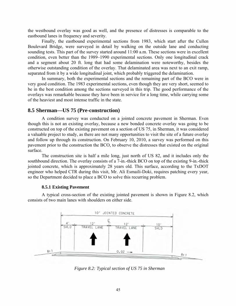
45
the westbound overlay was good as well, and the presence of distresses is comparable to the eastbound lanes in frequency and severity.
Finally, the eastbound experimental sections from 1983, which start after the Cullen Boulevard Bridge, were surveyed in detail by walking on the outside lane and conducting sounding tests. This part of the survey started around 11:00 a.m. These sections were in excellent condition, even better than the 1989–1990 experimental sections. Only one longitudinal crack and a segment about 20 ft. long that had some delamination were noteworthy, besides the otherwise outstanding condition of the overlay. That delaminated area was next to an exit ramp, separated from it by a wide longitudinal joint, which probably triggered the delamination.
In summary, both the experimental sections and the remaining part of the BCO were in very good condition. The 1983 experimental sections, even though they are very short, seemed to be in the best condition among the sections surveyed in this trip. The good performance of the overlays was remarkable because they have been in service for a long time, while carrying some of the heaviest and most intense traffic in the state.
8.5 Sherman—US 75 (Pre-construction)
A condition survey was conducted on a jointed concrete pavement in Sherman. Even though this is not an existing overlay, because a new bonded concrete overlay was going to be constructed on top of the existing pavement on a section of US 75, in Sherman, it was considered a valuable project to study, as there are not many opportunities to visit the site of a future overlay and follow up through its construction. On February 10, 2010, a survey was performed on this pavement prior to the construction the BCO, to observe the distresses that existed on the original surface.
The construction site is half a mile long, just north of US 82, and it includes only the southbound direction. The overlay consists of a 7-in.-thick BCO on top of the existing 9-in.-thick jointed concrete, which is approximately 28 years old. This surface, according to the TxDOT engineer who helped CTR during this visit, Mr. Ali Esmaili-Doki, requires patching every year, so the Department decided to place a BCO to solve this recurring problem.
8.5.1 Existing Pavement
A typical cross-section of the existing jointed pavement is shown in Figure 8.2, which consists of two main lanes with shoulders on either side.
Figure 8.2: Typical section of US 75 in Sherman
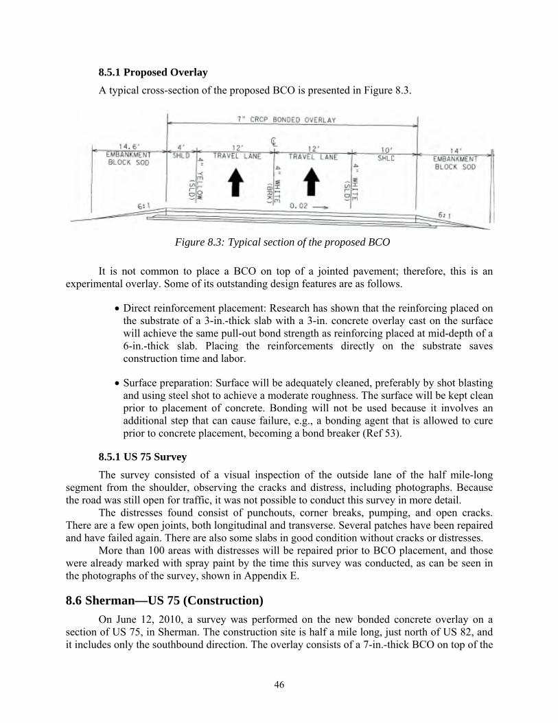
46
8.5.1 Proposed Overlay
A typical cross-section of the proposed BCO is presented in Figure 8.3.
Figure 8.3: Typical section of the proposed BCO
It is not common to place a BCO on top of a jointed pavement; therefore, this is an experimental overlay. Some of its outstanding design features are as follows.
Direct reinforcement placement: Research has shown that the reinforcing placed on the substrate of a 3-in.-thick slab with a 3-in. concrete overlay cast on the surface will achieve the same pull-out bond strength as reinforcing placed at mid-depth of a 6-in.-thick slab. Placing the reinforcements directly on the substrate saves construction time and labor.
Surface preparation: Surface will be adequately cleaned, preferably by shot blasting and using steel shot to achieve a moderate roughness. The surface will be kept clean prior to placement of concrete. Bonding will not be used because it involves an additional step that can cause failure, e.g., a bonding agent that is allowed to cure prior to concrete placement, becoming a bond breaker (Ref 53).
8.5.1 US 75 Survey
The survey consisted of a visual inspection of the outside lane of the half mile-long segment from the shoulder, observing the cracks and distress, including photographs. Because the road was still open for traffic, it was not possible to conduct this survey in more detail.
The distresses found consist of punchouts, corner breaks, pumping, and open cracks. There are a few open joints, both longitudinal and transverse. Several patches have been repaired and have failed again. There are also some slabs in good condition without cracks or distresses.
More than 100 areas with distresses will be repaired prior to BCO placement, and those were already marked with spray paint by the time this survey was conducted, as can be seen in the photographs of the survey, shown in Appendix E.
8.6 Sherman—US 75 (Construction)
On June 12, 2010, a survey was performed on the new bonded concrete overlay on a section of US 75, in Sherman. The construction site is half a mile long, just north of US 82, and it includes only the southbound direction. The overlay consists of a 7-in.-thick BCO on top of the

47
existing 9-in.-thick jointed concrete, which is approximately 28 years old. This surface, according to the TxDOT engineer who helped CTR during this visit, Mr. Ali Esmaili-Doki, requires patching every year, so the Department has decided on the placement of a BCO to solve this recurring problem.
The survey consisted of visually inspecting the construction of the outside lane of the half a mile-long segment taking photographs. The prepared surface was checked to see if there was any possible debris that would cause debonding and if the surface ahead of the paver was kept in saturated surface dry (SSD) condition by spraying water. Also, quality control was performed by monitoring the construction, finishing, and curing process.
8.6.1 Surface Preparation and Placement of Reinforcements
The surface was roughened up and cleaned before the BCO placement. However, the survey team noticed that the yellow pavement stripe was still intact, which raised a concern for the possibility of the stripe acting as a debonder. Therefore, the contractor was asked to remove the yellow stripe and thoroughly clean the surface again before the construction began. Figure 8.4 shows the pavement before the yellow strip was removed, and Figure 8.5 shows it after removal.
Figure 8.4: Prepared surface prior to the yellow stripe removal

48
Figure 8.5: After the removal of the yellow stripe
Because the BCO was relatively thick to provide enough concrete cover for reinforcement bars, reinforcements were placed on top of the prepared surface of the existing pavement. Figure 8.6 shows that chairs were used to elevate the reinforcement bars. The workers were asked to wet the surface before the construction began.
Figure 8.6: Reinforcement detail
The transition reinforcement details are provided in Figures 8.7 and 8.8. Transition areas typically have the highest concentration of traffic load; therefore, proper reinforcement is very important. If a bond fails at a transition area, the failure can propagate through the concrete
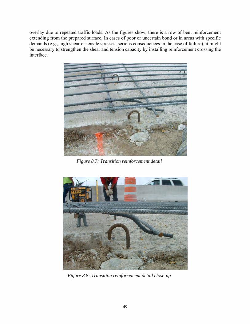
49
overlay due to repeated traffic loads. As the figures show, there is a row of bent reinforcement extending from the prepared surface. In cases of poor or uncertain bond or in areas with specific demands (e.g., high shear or tensile stresses, serious consequences in the case of failure), it might be necessary to strengthen the shear and tension capacity by installing reinforcement crossing the interface.
Figure 8.7: Transition reinforcement detail
Figure 8.8: Transition reinforcement detail close-up
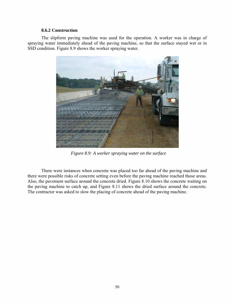
50
8.6.2 Construction
The slipform paving machine was used for the operation. A worker was in charge of spraying water immediately ahead of the paving machine, so that the surface stayed wet or in SSD condition. Figure 8.9 shows the worker spraying water.
Figure 8.9: A worker spraying water on the surface
There were instances when concrete was placed too far ahead of the paving machine and there were possible risks of concrete setting even before the paving machine reached those areas. Also, the pavement surface around the concrete dried. Figure 8.10 shows the concrete waiting on the paving machine to catch up, and Figure 8.11 shows the dried surface around the concrete. The contractor was asked to slow the placing of concrete ahead of the paving machine.
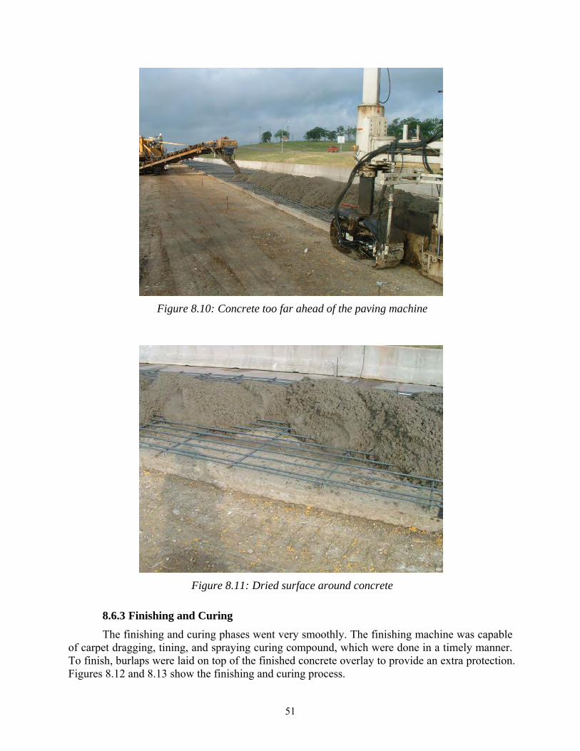
51
Figure 8.10: Concrete too far ahead of the paving machine
Figure 8.11: Dried surface around concrete
8.6.3 Finishing and Curing
The finishing and curing phases went very smoothly. The finishing machine was capable of carpet dragging, tining, and spraying curing compound, which were done in a timely manner. To finish, burlaps were laid on top of the finished concrete overlay to provide an extra protection. Figures 8.12 and 8.13 show the finishing and curing process.
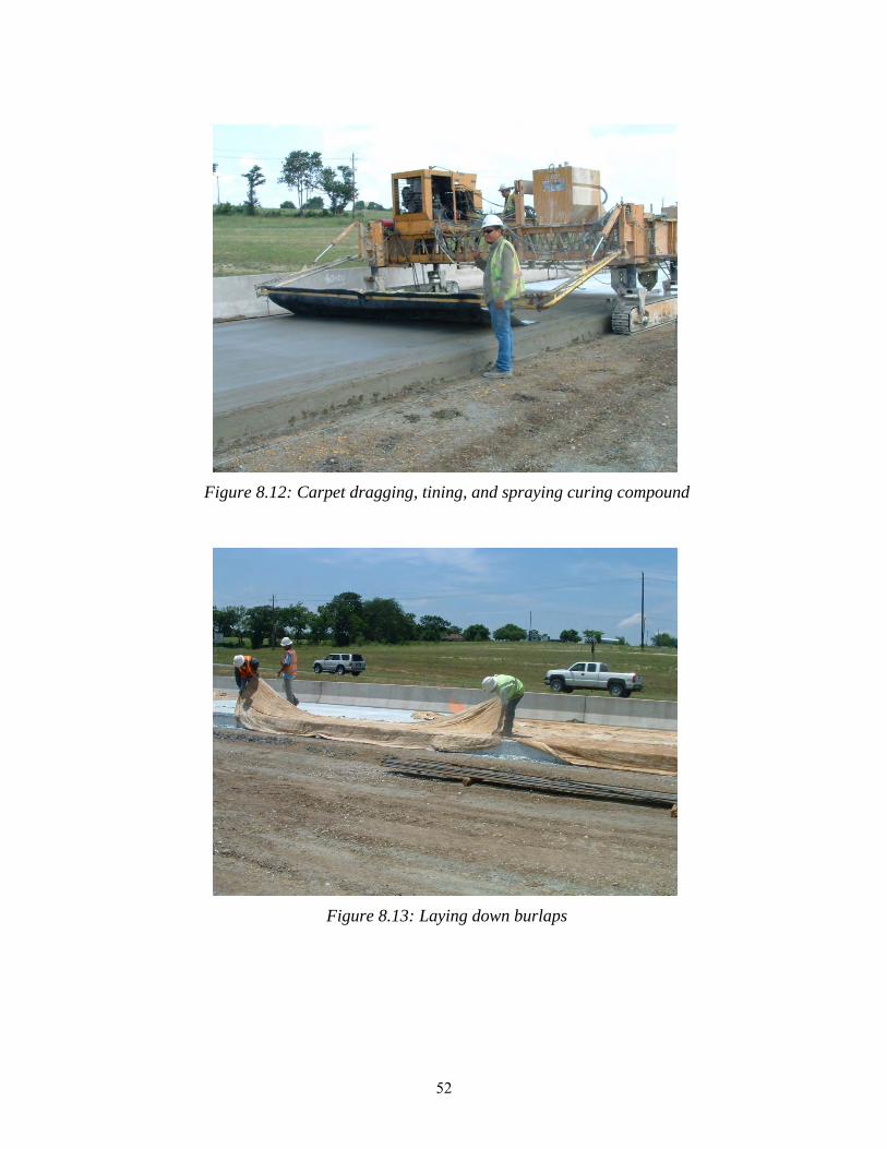
52
Figure 8.12: Carpet dragging, tining, and spraying curing compound
Figure 8.13: Laying down burlaps
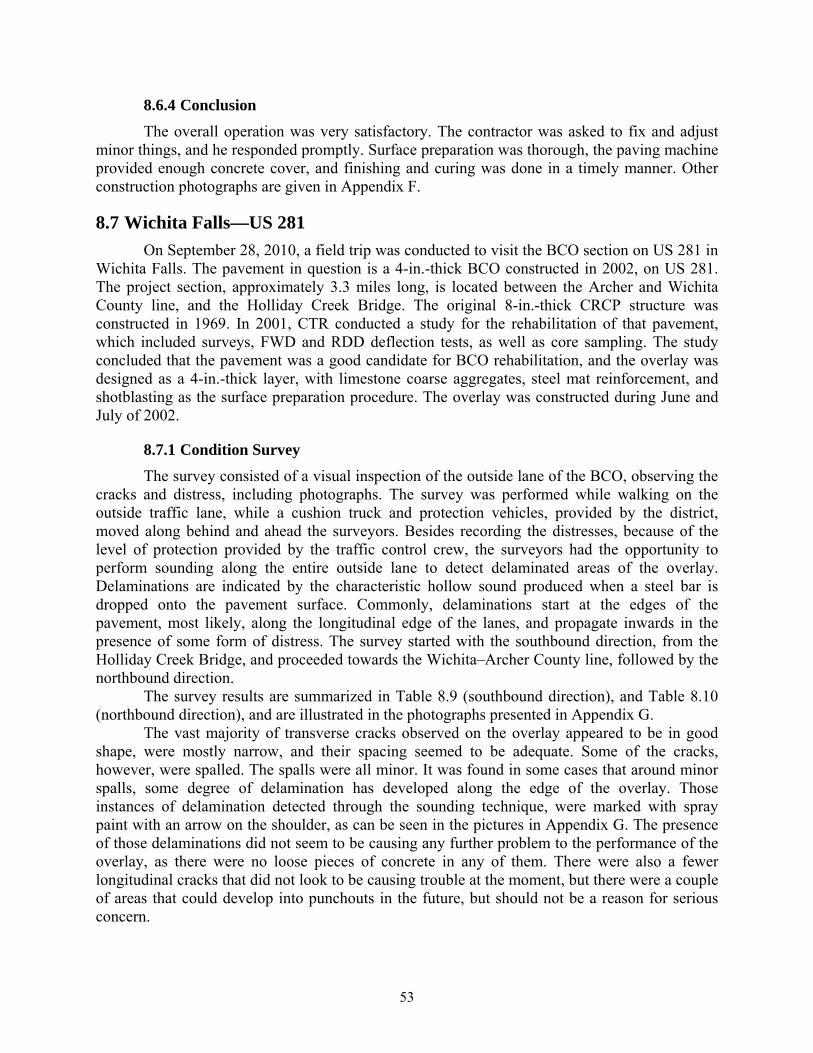
53
8.6.4 Conclusion
The overall operation was very satisfactory. The contractor was asked to fix and adjust minor things, and he responded promptly. Surface preparation was thorough, the paving machine provided enough concrete cover, and finishing and curing was done in a timely manner. Other construction photographs are given in Appendix F.
8.7 Wichita Falls—US 281
On September 28, 2010, a field trip was conducted to visit the BCO section on US 281 in Wichita Falls. The pavement in question is a 4-in.-thick BCO constructed in 2002, on US 281. The project section, approximately 3.3 miles long, is located between the Archer and Wichita County line, and the Holliday Creek Bridge. The original 8-in.-thick CRCP structure was constructed in 1969. In 2001, CTR conducted a study for the rehabilitation of that pavement, which included surveys, FWD and RDD deflection tests, as well as core sampling. The study concluded that the pavement was a good candidate for BCO rehabilitation, and the overlay was designed as a 4-in.-thick layer, with limestone coarse aggregates, steel mat reinforcement, and shotblasting as the surface preparation procedure. The overlay was constructed during June and July of 2002.
8.7.1 Condition Survey
The survey consisted of a visual inspection of the outside lane of the BCO, observing the cracks and distress, including photographs. The survey was performed while walking on the outside traffic lane, while a cushion truck and protection vehicles, provided by the district, moved along behind and ahead the surveyors. Besides recording the distresses, because of the level of protection provided by the traffic control crew, the surveyors had the opportunity to perform sounding along the entire outside lane to detect delaminated areas of the overlay. Delaminations are indicated by the characteristic hollow sound produced when a steel bar is dropped onto the pavement surface. Commonly, delaminations start at the edges of the pavement, most likely, along the longitudinal edge of the lanes, and propagate inwards in the presence of some form of distress. The survey started with the southbound direction, from the Holliday Creek Bridge, and proceeded towards the Wichita–Archer County line, followed by the northbound direction.
The survey results are summarized in Table 8.9 (southbound direction), and Table 8.10 (northbound direction), and are illustrated in the photographs presented in Appendix G.
The vast majority of transverse cracks observed on the overlay appeared to be in good shape, were mostly narrow, and their spacing seemed to be adequate. Some of the cracks, however, were spalled. The spalls were all minor. It was found in some cases that around minor spalls, some degree of delamination has developed along the edge of the overlay. Those instances of delamination detected through the sounding technique, were marked with spray paint with an arrow on the shoulder, as can be seen in the pictures in Appendix G. The presence of those delaminations did not seem to be causing any further problem to the performance of the overlay, as there were no loose pieces of concrete in any of them. There were also a fewer longitudinal cracks that did not look to be causing trouble at the moment, but there were a couple of areas that could develop into punchouts in the future, but should not be a reason for serious concern.

54
Throughout the entire BCO section there was one serious problem that stood out. It was a large punchout that developed at a transverse joint on the inside lane only, in the southbound direction, between 2.1 and 2.2 miles from the start of the overlay section. The survey, as mentioned above, was conducted on the outside lanes only, but the presence of this distress was very noticeable. The punchout extends for the entire width of the lane.
Other than the few delaminated areas and the minor spalls, the condition of the pavement was very good. In general, the northbound direction could be considered in slightly better shape than the southbound, only because there were fewer spalls in the northbound BCO, but the aspect of the cracks, spalls, and delaminations was very similar for both directions.
Table 8.9: US 281 survey—southbound direction
Cumulative Minor Distance (ft) Spalls
0.0 to 0.1 528 10.1 to 0.2 1056 3 1 Small delamination at construction joint (966)0.2 to 0.3 1584 1 Diamond grinding starts at 11600.3 to 0.4 2112 Diamond grinding ends at 19140.4 to 0.5 2640 20.5 to 0.6 31680.6 to 0.7 3696 Bridge starts at 36200.7 to 0.8 42240.8 to 0.9 47520.9 to 1.0 52801.0 to 1.1 5808 3 Bridge ends at 54201.1 to 1.2 63361.2 to 1.3 6864 2 Small delamination at 6450
Small delamination at 6666Bridge starts at 6819RM 194 at 7148
1.3 to 1.4 73921.4 to 1.5 79201.5 to 1.6 84481.6 to 1.7 8976 2 Bridge ends at 86291.7 to 1.8 9504 51.8 to 1.9 10032 11.9 to 2.0 10560 22.0 to 2.1 11088 12.1 to 2.2 11616 1 Punchout at joint (inside lane)2.2 to 2.3 12144 Bridge starts at 117922.3 to 2.4 126722.4 to 2.5 132002.5 to 2.6 13728 Bridge ends at 136642.6 to 2.7 14256 12.7 to 2.8 147842.8 to 2.9 15312 1 Small delamination at 151882.9 to 3.0 15840 Bridge starts at 155823.0 to 3.1 163683.1 to 3.2 168963.2 to 3.3 17420 RM 196 at 17341
End of BCO at 17420
Mileage CommentsDelaminations
55
Table 8.10: US 281 survey—eastbound direction
8.8 Laredo—IH 35
On December 15, 2009, a survey was performed on the Laredo Whitetopping Project on IH 35. The segment in question is located north of Laredo, near Artesia Wells in LaSalle County, between mileposts 51 and 52. The IH 35 Whitetopping section, placed on the northbound lanes only, was constructed in December of 2001 and January of 2002, and consists of a 9-in.-thick layer of CRCP on top of the existing ACP, from which approximately 3 inches were milled off (Ref 35).
Cumulative Minor Distance (ft) Spalls
0.0 to 0.1 528 RM 196 at 81Bridge
0.1 to 0.2 10560.2 to 0.3 15840.3 to 0.4 2112 3 Bridge ends at 18120.4 to 0.5 2640 1 1 Small delamination at 24850.5 to 0.6 3168 4 1 Large delaminated area at 28760.6 to 0.7 3696 Bridge starts at 34780.7 to 0.8 42240.8 to 0.9 47520.9 to 1.0 52801.0 to 1.1 58081.1 to 1.2 6336 Bridge ends at 62351.2 to 1.3 68641.3 to 1.4 73921.4 to 1.5 7920 11.5 to 1.6 8448 1 1 Small delamination at 87461.6 to 1.7 8976 Bridge starts at 87801.7 to 1.8 95041.8 to 1.9 100321.9 to 2.0 10560 RM 194 at 102442.0 to 2.1 11088 Bridge ends at 105642.1 to 2.2 116162.2 to 2.3 12144 Bridge starts at 119562.3 to 2.4 126722.4 to 2.5 132002.5 to 2.6 137282.6 to 2.7 14256 Bridge ends at 137492.7 to 2.8 147842.8 to 2.9 15312 1 1 Small delamination at 148772.9 to 3.0 15840 13.0 to 3.1 163683.1 to 3.2 16896 13.2 to 3.3 17424
17631 End of BCO at 17631
Mileage CommentsDelaminations

56
This project has been monitored by CTR since its construction. The fact that two other surveys have been conducted before the current one allows for an evaluation of its performance over time.
The survey this time consisted of a visual inspection of the outside lane of the mile-long segment from the shoulder, recording the location of every crack and distress, including photographs. In the next section, some of the details of the overlay construction are presented.
8.8.1 IH 35 Whitetopping Construction
Being an experimental project, a number of features related to the design and construction of the overlay were carefully selected to insure its success over time. The first one of them was the time of placement for the concrete pavement. Over a number of years of observing PCC pavement performance using a rigid pavement database system and other studies, it has been found that pavements constructed under extremely hot conditions have a higher probability of developing failures, because of the increased climatic stresses, which in turn result in cracking. The adverse climatic conditions subject the freshly placed concrete to higher evaporation of water from the pavement surface, which may cause increased plastic shrinkage cracking. Furthermore, placing PCC on a hot AC surface can lead to excessive thermal restraint stresses resulting from the large gradient between the PCC at hardening and overnight low temperatures (Ref 12). Therefore, any construction during the summer months was ruled out for this project, and it was recommended to schedule the construction for the winter months.
In order to provide a structure able to carry the heavy traffic that traverses IH 35, PCC shoulders were used in lieu of asphalt shoulders. Tied PCC shoulders provide support to the edge of the slab, where the stress concentration is critical, thus, reducing the stresses and deflections in the main slab, decreasing fatigue and damage. Also, the tied PCC shoulders are better able to carry main lane traffic during construction and maintenance operations.
Excellent performance has been experienced over the state where pavements have been constructed using coarse aggregates with low coefficient of thermal expansion and lower modulus of elasticity (Ref 54). Generally, these characteristics are provided by coarse aggregates from limestone. Hence, considering the availability of aggregates in the area, the specification required that a limestone source be used, establishing a limit design value of 5.5x10⁻⁶/°F for the coefficient of thermal expansion.
Another critical design feature was the requirement for a carpet drag finish in lieu of tining. Tining has evolved as the standard finishing for PCC pavements, and has generally been required by the FHWA since the 1970s. The need for tining originated from efforts to eliminate hydroplaning where concrete pavements had polished to a glass-like finish (Ref 55).
In Texas, at the same time that some early pavements were tined, limestone fines had been eliminated from use in PCC paving mixes by the use of an acid insoluble test. In parallel to this development, several extensive studies in Texas have found a major loss of pavement performance due to spalling that occurs as a consequence of the delay that the tining operations cause in the placement of the curing compound (Ref 54 and 56). When the pavement is tined, the curing compound is not applied immediately, because the concrete is allowed to take its initial set so that the surface can be properly tined. During this period there may be a considerable loss of moisture in the pavement, and consequently, an increase in the incidence of plastic shrinkage cracking, which in turn, may result in spalling. Studies comparing pavements constructed with tining and normal carpet drag finish have found that the accident rates are similar for both surface finishings when the limestone fines had been eliminated. Thus,
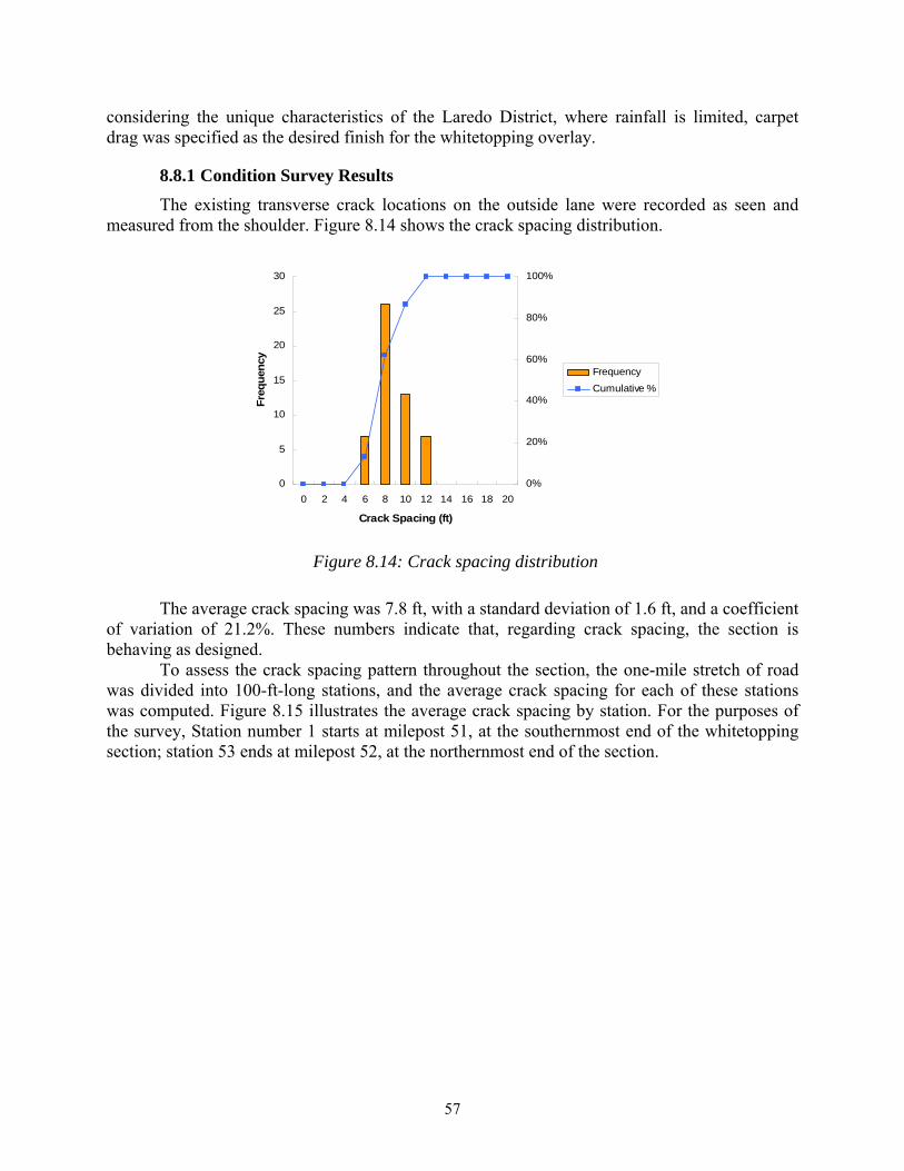
57
considering the unique characteristics of the Laredo District, where rainfall is limited, carpet drag was specified as the desired finish for the whitetopping overlay.
8.8.1 Condition Survey Results
The existing transverse crack locations on the outside lane were recorded as seen and measured from the shoulder. Figure 8.14 shows the crack spacing distribution.
Figure 8.14: Crack spacing distribution
The average crack spacing was 7.8 ft, with a standard deviation of 1.6 ft, and a coefficient of variation of 21.2%. These numbers indicate that, regarding crack spacing, the section is behaving as designed. To assess the crack spacing pattern throughout the section, the one-mile stretch of road was divided into 100-ft-long stations, and the average crack spacing for each of these stations was computed. Figure 8.15 illustrates the average crack spacing by station. For the purposes of the survey, Station number 1 starts at milepost 51, at the southernmost end of the whitetopping section; station 53 ends at milepost 52, at the northernmost end of the section.
0
5
10
15
20
25
30
0 2 4 6 8 10 12 14 16 18 20
Crack Spacing (ft)
Fre
qu
ency
0%
20%
40%
60%
80%
100%
Frequency
Cumulative %
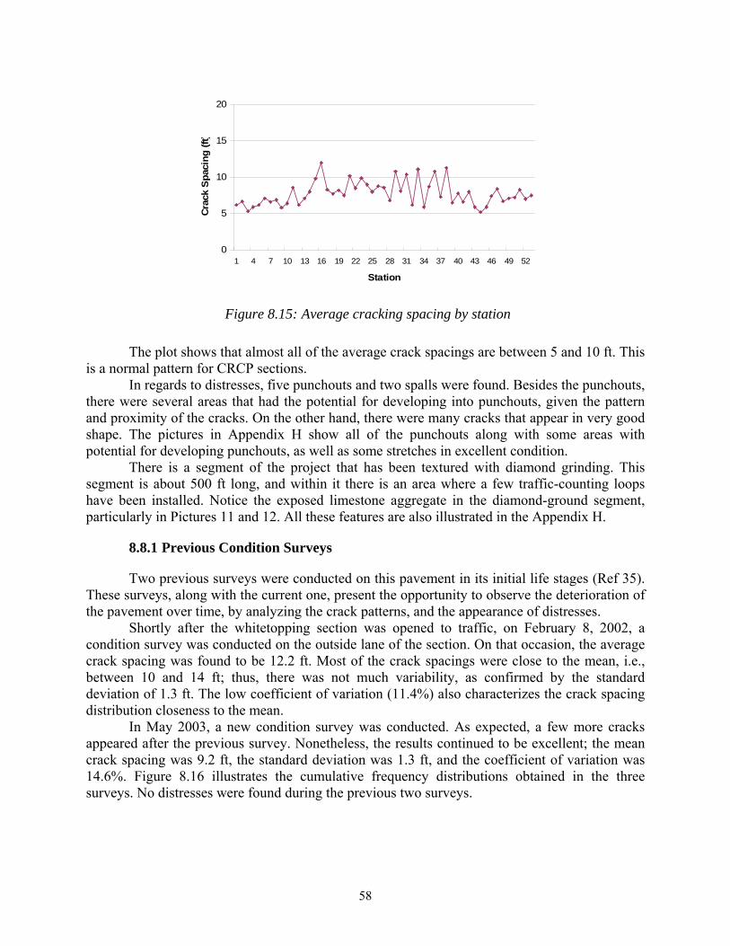
58
Figure 8.15: Average cracking spacing by station
The plot shows that almost all of the average crack spacings are between 5 and 10 ft. This is a normal pattern for CRCP sections. In regards to distresses, five punchouts and two spalls were found. Besides the punchouts, there were several areas that had the potential for developing into punchouts, given the pattern and proximity of the cracks. On the other hand, there were many cracks that appear in very good shape. The pictures in Appendix H show all of the punchouts along with some areas with potential for developing punchouts, as well as some stretches in excellent condition. There is a segment of the project that has been textured with diamond grinding. This segment is about 500 ft long, and within it there is an area where a few traffic-counting loops have been installed. Notice the exposed limestone aggregate in the diamond-ground segment, particularly in Pictures 11 and 12. All these features are also illustrated in the Appendix H.
8.8.1 Previous Condition Surveys
Two previous surveys were conducted on this pavement in its initial life stages (Ref 35). These surveys, along with the current one, present the opportunity to observe the deterioration of the pavement over time, by analyzing the crack patterns, and the appearance of distresses. Shortly after the whitetopping section was opened to traffic, on February 8, 2002, a condition survey was conducted on the outside lane of the section. On that occasion, the average crack spacing was found to be 12.2 ft. Most of the crack spacings were close to the mean, i.e., between 10 and 14 ft; thus, there was not much variability, as confirmed by the standard deviation of 1.3 ft. The low coefficient of variation (11.4%) also characterizes the crack spacing distribution closeness to the mean. In May 2003, a new condition survey was conducted. As expected, a few more cracks appeared after the previous survey. Nonetheless, the results continued to be excellent; the mean crack spacing was 9.2 ft, the standard deviation was 1.3 ft, and the coefficient of variation was 14.6%. Figure 8.16 illustrates the cumulative frequency distributions obtained in the three surveys. No distresses were found during the previous two surveys.
0
5
10
15
20
1 4 7 10 13 16 19 22 25 28 31 34 37 40 43 46 49 52
Station
Cra
ck S
pac
ing
(ft
)
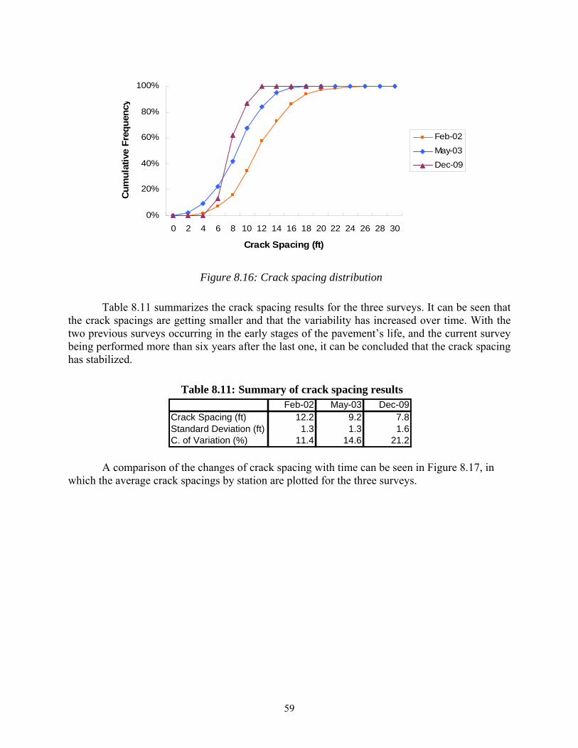
59
Figure 8.16: Crack spacing distribution
Table 8.11 summarizes the crack spacing results for the three surveys. It can be seen that the crack spacings are getting smaller and that the variability has increased over time. With the two previous surveys occurring in the early stages of the pavement’s life, and the current survey being performed more than six years after the last one, it can be concluded that the crack spacing has stabilized.
Table 8.11: Summary of crack spacing results
A comparison of the changes of crack spacing with time can be seen in Figure 8.17, in which the average crack spacings by station are plotted for the three surveys.
0%
20%
40%
60%
80%
100%
0 2 4 6 8 10 12 14 16 18 20 22 24 26 28 30
Crack Spacing (ft)
Cu
mu
lati
ve F
req
uen
cyFeb-02
May-03
Dec-09
Feb-02 May-03 Dec-09Crack Spacing (ft) 12.2 9.2 7.8Standard Deviation (ft) 1.3 1.3 1.6C. of Variation (%) 11.4 14.6 21.2
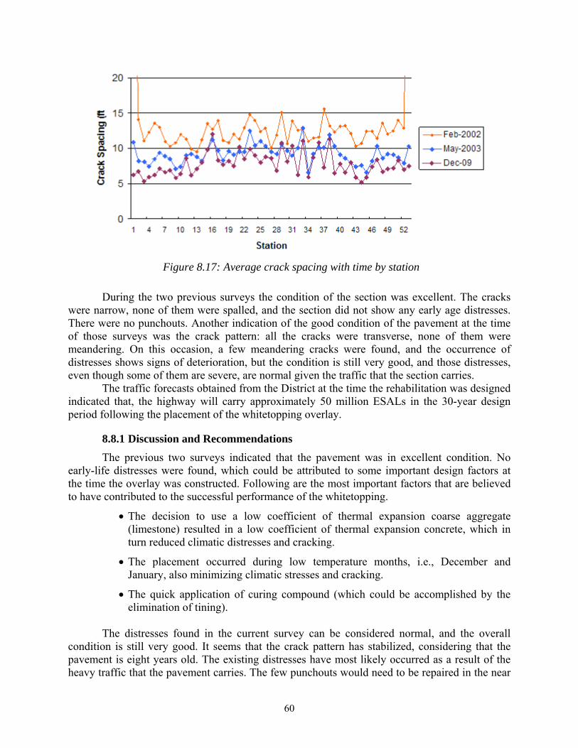
60
Figure 8.17: Average crack spacing with time by station
During the two previous surveys the condition of the section was excellent. The cracks were narrow, none of them were spalled, and the section did not show any early age distresses. There were no punchouts. Another indication of the good condition of the pavement at the time of those surveys was the crack pattern: all the cracks were transverse, none of them were meandering. On this occasion, a few meandering cracks were found, and the occurrence of distresses shows signs of deterioration, but the condition is still very good, and those distresses, even though some of them are severe, are normal given the traffic that the section carries.
The traffic forecasts obtained from the District at the time the rehabilitation was designed indicated that, the highway will carry approximately 50 million ESALs in the 30-year design period following the placement of the whitetopping overlay.
8.8.1 Discussion and Recommendations
The previous two surveys indicated that the pavement was in excellent condition. No early-life distresses were found, which could be attributed to some important design factors at the time the overlay was constructed. Following are the most important factors that are believed to have contributed to the successful performance of the whitetopping.
The decision to use a low coefficient of thermal expansion coarse aggregate (limestone) resulted in a low coefficient of thermal expansion concrete, which in turn reduced climatic distresses and cracking.
The placement occurred during low temperature months, i.e., December and January, also minimizing climatic stresses and cracking.
The quick application of curing compound (which could be accomplished by the elimination of tining).
The distresses found in the current survey can be considered normal, and the overall
condition is still very good. It seems that the crack pattern has stabilized, considering that the pavement is eight years old. The existing distresses have most likely occurred as a result of the heavy traffic that the pavement carries. The few punchouts would need to be repaired in the near
61
future to prevent further deterioration. Those few locations will need full-depth repairs. Further evaluation to assess the extent of the need for full-depth repairs at those locations will include sounding, which could indicate the possibility of delaminated areas in the vicinity of the punchouts. An even more comprehensive evaluation could be done by the measurement of deflections. Regarding the spalls, it seems that the few existing spalls are of low severity, and will not affect the ride quality, so those may not require repair for the time being, or perhaps some patching could be enough for those repairs in the future.
8.9 El Paso—IH 10
On October 20 and 21, 2010, CTR conducted a field trip to the site of the BCO section on IH 10 in El Paso. The overlay in question is significantly thicker (6.5-in.) than other BCOs in Texas studied under this project. The project was intended as an expedited BCO when it was constructed. Between Franklin St. Bridge and Missouri St. Bridge in downtown El Paso lies a segment of IH 10 known as the “depressed section” because it goes from four lanes in each direction to three lanes without a decrease in traffic (Ref 57). It has heavy traffic and the District asked the researchers to conduct the survey after 10:00 p.m., so that the traffic would be less intense and allow for lane closures.
The original pavement section consisted of 8-in.-thick CRCP built in 1965; a feasibility study recommended that this section could be rehabilitated with a BCO in 1993 (Ref 57). In June and July of 1996, a segment about three-quarters of a mile long in each direction was overlaid with a BCO.
The overlay was planned as an expedited BCO (Ref 58 and 59), which means that paving methods were planned to reduce the normal time between placement and opening the lanes to traffic. With this, the overall cost of the project would have been reduced and the burden to the public originated by lane closures and detours would have been diminished.
However, in spite of the planning and research invested in the project, problems with the concrete mixture resulted in the delamination of most of the eastbound and some of the westbound BCO. Shortly after construction, some delaminations were identified during the extraction of core samples from the pavement. Coring and seismic tests confirmed the severity and extension of the delaminations. The comprehensive investigation that followed these events identified the high amount of water lost by the concrete before the curing compound was applied as the major cause of the debonding problem. A number of factors contributed to these unusual moisture losses from the concrete: the delay in applying the curing compound in conjunction with high evaporation rates and inadequate surface preparation originated a stiff mixture, not workable, which had lost its adhesion. The mixture had low water content to begin with, because of the higher strength requirement of an expedited BCO. Then, the surface of the existing pavement slab was not dampened before placing the overlay, which caused moisture losses through the bottom of the slab. To prevent these water losses, the substrate surface should have been prepared by spraying water on it before pouring the concrete (Ref 45).
The BCO had to be repaired by means of injected epoxy into spaced holes in order to bond the delaminated overlay to the existing surface. The repair work took three weeks to complete, and Falling Weight Deflectometer (FWD) tests confirmed the success of the remedy. However, subsequent pullout tests indicated that some areas were not completely filled with epoxy, and some locations had deflections higher than expected so it was considered at the time that those areas were still debonded (Ref 45). These observations from shortly after the repairs were finished to support the results observed in this survey.
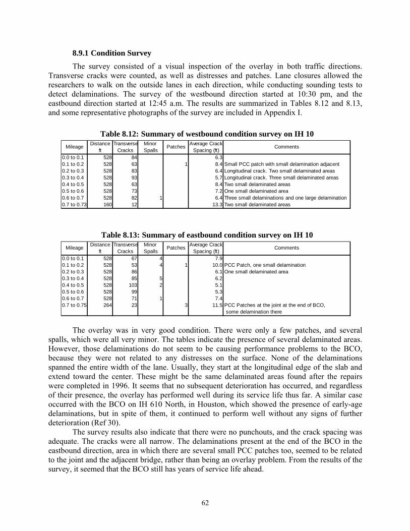
62
8.9.1 Condition Survey
The survey consisted of a visual inspection of the overlay in both traffic directions. Transverse cracks were counted, as well as distresses and patches. Lane closures allowed the researchers to walk on the outside lanes in each direction, while conducting sounding tests to detect delaminations. The survey of the westbound direction started at 10:30 pm, and the eastbound direction started at 12:45 a.m. The results are summarized in Tables 8.12 and 8.13, and some representative photographs of the survey are included in Appendix I.
Table 8.12: Summary of westbound condition survey on IH 10
Table 8.13: Summary of eastbound condition survey on IH 10
The overlay was in very good condition. There were only a few patches, and several spalls, which were all very minor. The tables indicate the presence of several delaminated areas. However, those delaminations do not seem to be causing performance problems to the BCO, because they were not related to any distresses on the surface. None of the delaminations spanned the entire width of the lane. Usually, they start at the longitudinal edge of the slab and extend toward the center. These might be the same delaminated areas found after the repairs were completed in 1996. It seems that no subsequent deterioration has occurred, and regardless of their presence, the overlay has performed well during its service life thus far. A similar case occurred with the BCO on IH 610 North, in Houston, which showed the presence of early-age delaminations, but in spite of them, it continued to perform well without any signs of further deterioration (Ref 30).
The survey results also indicate that there were no punchouts, and the crack spacing was adequate. The cracks were all narrow. The delaminations present at the end of the BCO in the eastbound direction, area in which there are several small PCC patches too, seemed to be related to the joint and the adjacent bridge, rather than being an overlay problem. From the results of the survey, it seemed that the BCO still has years of service life ahead.
Distance Transverse Minor Average Crackft Cracks Spalls Spacing (ft)
0.0 to 0.1 528 84 6.30.1 to 0.2 528 63 1 8.4 Small PCC patch with small delamination adjacent0.2 to 0.3 528 83 6.4 Longitudinal crack. Two small delaminated areas0.3 to 0.4 528 93 5.7 Longitudinal crack. Three small delaminated areas0.4 to 0.5 528 63 8.4 Two small delaminated areas0.5 to 0.6 528 73 7.2 One small delaminated area0.6 to 0.7 528 82 1 6.4 Three small delaminations and one large delamination0.7 to 0.73 160 12 13.3 Two small delaminated areas
Mileage CommentsPatches
Distance Transverse Minor Average Crackft Cracks Spalls Spacing (ft)
0.0 to 0.1 528 67 4 7.90.1 to 0.2 528 53 4 1 10.0 PCC Patch, one small delamination0.2 to 0.3 528 86 6.1 One small delaminated area0.3 to 0.4 528 85 5 6.20.4 to 0.5 528 103 2 5.10.5 to 0.6 528 99 5.30.6 to 0.7 528 71 1 7.40.7 to 0.75 264 23 3 11.5 PCC Patches at the joint at the end of BCO,
some delamination there
Mileage CommentsPatches
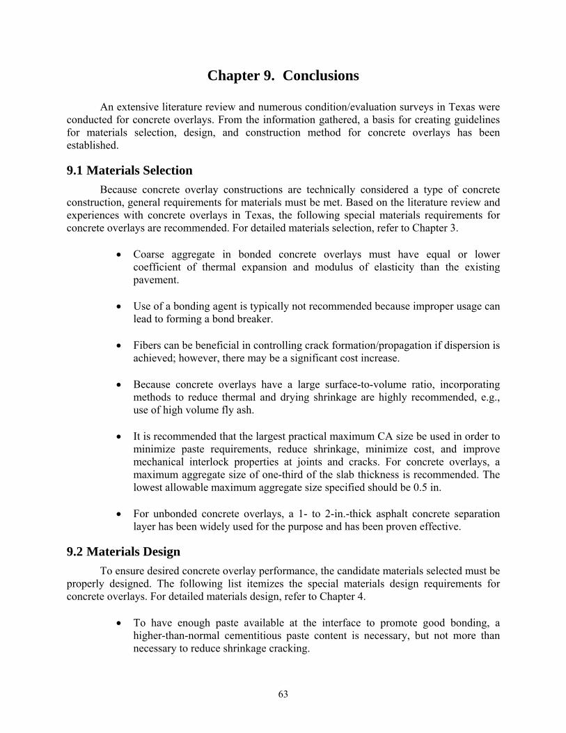
63
Chapter 9. Conclusions
An extensive literature review and numerous condition/evaluation surveys in Texas were conducted for concrete overlays. From the information gathered, a basis for creating guidelines for materials selection, design, and construction method for concrete overlays has been established.
9.1 Materials Selection
Because concrete overlay constructions are technically considered a type of concrete construction, general requirements for materials must be met. Based on the literature review and experiences with concrete overlays in Texas, the following special materials requirements for concrete overlays are recommended. For detailed materials selection, refer to Chapter 3.
Coarse aggregate in bonded concrete overlays must have equal or lower
coefficient of thermal expansion and modulus of elasticity than the existing pavement.
Use of a bonding agent is typically not recommended because improper usage can lead to forming a bond breaker.
Fibers can be beneficial in controlling crack formation/propagation if dispersion is
achieved; however, there may be a significant cost increase.
Because concrete overlays have a large surface-to-volume ratio, incorporating methods to reduce thermal and drying shrinkage are highly recommended, e.g., use of high volume fly ash.
It is recommended that the largest practical maximum CA size be used in order to
minimize paste requirements, reduce shrinkage, minimize cost, and improve mechanical interlock properties at joints and cracks. For concrete overlays, a maximum aggregate size of one-third of the slab thickness is recommended. The lowest allowable maximum aggregate size specified should be 0.5 in.
For unbonded concrete overlays, a 1- to 2-in.-thick asphalt concrete separation
layer has been widely used for the purpose and has been proven effective.
9.2 Materials Design
To ensure desired concrete overlay performance, the candidate materials selected must be properly designed. The following list itemizes the special materials design requirements for concrete overlays. For detailed materials design, refer to Chapter 4.
To have enough paste available at the interface to promote good bonding, a higher-than-normal cementitious paste content is necessary, but not more than necessary to reduce shrinkage cracking.
64
Coupled with cement paste content, the w/cm must be sufficiently high to promote enough paste available at the surface.
The use of the maximum allowed amount of fly ash is highly recommended.
If economically feasible, the use of the manufacturer’s recommended dosage of
fibers is recommended. When using fibers, the focus should be on proper fiber dispersion in concrete to prevent balling.
Admixture dosage and types are different in each project. Sample batches must be
made in order to properly design the mixture when using various admixtures.
9.3 Construction Methods
9.3.1 Environmental Limitations
Even if the materials are selected and designed properly, the use of proper construction methods is essential to achieving the desired performance of concrete overlays. The following limits must be monitored during construction.
Surface of the existing pavement should not exceed 125 °F immediately before placement.
Air temperature differential within 24 hours after the placement must be less than 25 °F.
Water evaporation rates should not exceed 0.2 lb/ft²/hr based on air temperature, concrete temperature, wind speed, and relative humidity as noted in the ACI Hot Weather Concreting nomograph.
The use of weather stations is recommended during concrete placement to monitor evaporation rates. If any of these limits are exceeded during the placement of concrete, the placement should be avoided unless following conditions can be achieved.
Cooling the aggregate or concrete.
Special curing methods (see section 2.3.7).
Use of fly ash as cement replacement to lower the heat of hydration
9.3.2 Surface Preparation
Surface preparation and cleaning is the most important factor that determines the performance and the longevity of concrete overlays. Each type of concrete overlay requires different procedures, and the following guidelines should be used.
Bonded Concrete Overlays: Before surface preparation of the existing concrete
pavement, any existing asphalt patches or other unsound materials should be removed. After texturing (by shotblasting, for example), the surface should be thoroughly cleaned so as to not leave any foreign materials or debris that may act as bond breakers. Before placing concrete, the prepared and cleaned surface
65
should be in a saturated surface dry condition (SSD) to prevent absorption of moisture from the fresh concrete by the existing pavement.
Whitetoppings: If surface distortions on the existing asphalt pavement are excessive (greater than 2-in.), either milling or a leveling course may be necessary to provide proper grading. The surface should then be prepared by milling to give texture to the existing pavement. Some methods, such as white pigmented curing and water fogging, can be used to cool the prepared surface just before the concrete placement in order to prevent heat build-up.
Unbonded Concrete Overlays: Because the existing pavement acts as a subbase,
no special preparation is required. However, seriously damaged areas must be repaired in order to place the separation layer on top. Typically, a 1- to 2-in.-thick asphalt layer is used as a separation layer to prevent bonding to the existing concrete pavement. Once the separation layer is in place, the surface is treated as whitetopping.
9.3.3 Surface Cleaning
Once the surface preparation is finished, proper surface cleaning is required. Foreign objects, loose materials, and debris can act as bond breakers resulting in delamination and reduced overlay life. Shotblasting should normally occur the day the overlay is applied, with airblasting just before concrete placement in order to remove dust or other containments. If water blasting is required for cleaning, the surface should be permitted to dry to a SSD condition. Removal of paint stripes, tire marks, or grout matrix may require additional methods of cleaning. It is important not to leave a large time lag between the final surface cleaning and paving in order to prevent the contaminants from resettling. If trucks or equipment must drive on top of prepared surface, tarpaulins or plastic layers should be placed in order to prevent any foreign materials falling on the surface. The ultimate goal in surface preparation is to achieve a well textured and clean surface to receive the concrete overlay.
9.3.4 Fiber Incorporation
For mixing, both steel and synthetic fibers can be packaged in water-soluble materials designed to break down in the mixer and allow the fibers to be evenly dispersed in the mixture. If not handled properly, in some instances remnants of the paper wrapper used to bundle the polyolefin fibers may appear in the mixture. To avoid producing fiber balls and uncoated fibers, fibers can be introduced into the mixture earlier; however, the mixing time should be slightly increased and the batch size should be reduced. These procedures may help, but not completely eliminate, the problem.
9.3.5 Placement
Below are general considerations for placement of concrete overlays.
To prevent water loss in concrete due to absorption by the existing pavement, the prepared surface ahead of the paving machine should be dampened with water to achieve a saturated surface dry condition.
66
Tracking of dirt, debris or runoff of contaminated water ahead of paving machine should be prevented.
Bonding agents should not be used unless under special circumstances. With a properly prepared surface in SSD condition, a bonding agent, such as epoxy or latex, is not required. If bonding agents are used improperly, they may act as bond breakers.
For BCOs, reinforcements can be directly placed on top of existing pavement—laboratory studies have shown that reinforcement placed at the interface develops the same bond as reinforcement placed in the middle of the overlay. Placement of the reinforcement at the interface also eliminates the risk of concrete honeycombing and poor consolidation beneath the steel.
The grading machine must be adjusted to achieve the required thickness of the concrete overlay.
The steel fibers at the surface of the pavement can become entangled with burlap and can be pulled out along with other fibers and coarse aggregates. An un-weighted carpet drag can be a substitution to provide a satisfactory interim surface finish on the pavement.
Finishing of the new concrete overlay surface should follow the same practices used to finish any concrete pavement.
9.3.6 Jointing
To reduce the edge and corner stresses, longitudinal joints should not be placed in the wheel path. Heavy loads concentrated near the edge of the thin panels should not exceed their load capacity.
The timing of joint sawing is critical. Sawing too early can cause excess raveling, and sawing too late can result in shrinkage stress, causing uncontrolled random cracking.
ACPA recommends that joint spacing be about 12 to 15 times the slab thickness.
Joint spacing has a significant effect on the rate of corner cracking. Short joint spacing, common on thin concrete overlays, reduces load-related stresses, because the slabs are not long enough to develop as much bending moment. The joint location is also important to avoid concentrated loads. For example, 4-ft by 4-ft panels on a 12-ft-wide lane would put truck tires on the edge of the panels, and significant distress would occur if the thin concrete overlays became de-bonded from the existing pavement. Figure 5.4 is a good example of failed joints in wheel paths.
9.3.7 Curing
Curing should begin as soon after placement and finishing as possible to minimize loss of bleed water. For concrete overlays, it is recommended that a double application of the curing compound be used.
67
Types of curing procedure include the following.
Curing compound: For textured or tined surfaces, the spray application should be applied from two directions to ensure that the entire surface is coated.
Membrane curing: Various liquid sealing compounds, e.g., bituminous and paraffinic emulsions, coal tar cut backs, pigmented and non-pigmented resin suspensions, or suspensions of wax or non-liquid protective coating such as sheet plastics or water proof paper, are used to restrict evaporation of water.
Curing blankets: A coving of sacks, mattings, burlap, straw, or other suitable paper is placed over the surface to reduce evaporation and to reduce the temperature reduction at the surface. When used to reduce evaporation the blankets are generally wetted.
Monomolecular film (MMF): MMFs are compounds that form a thin monomolecular film to reduce raid moisture loss from the concrete surface prior to curing. Another curing method should be used after the evaporation retardant is sprayed on. Research has shown, however, that the use of MMF followed by the application of curing compound does not consistently result in less evaporation than curing compound alone.

69
References
1. Wu, C.L., M. Tia, and B. Choubane, “Forensic Investigation of Ultrathin Whitetopping Pavements in Florida,” Journal of Performance of Constructed Facilities, ASCE, pp.78-88., Feb. 2007
2. McNeal, A.F., “Planning, Design and Construction of an Unbonded Concrete Overlay,” Illinois Department of Transportation, Report No. FHWA/IL/PR-122, Jul. 1996.
3. Heckel, L. B., “Performance of an Unbonded Concrete Overlay on I-74,” Report No. IL-PRR-140, Illinois Department of Transportation, Bureau of Materials and Physical Research, Apr. 2002.
4. Harrington, D., “Guide to Concrete Overlays,” National Concrete Pavement Technology Center, 2nd Edition, Sep. 2008.
5. McCullough, B. F., Fowler, D. W., “Bonded Concrete Overlay (BCO) Project Selection Design, and Construction,” Research Report 920-6F, Center for Transportation Research, The University of Texas at Austin, Texas, Nov. 1994.
6. Delatte, N., A. Sehdev, “Mechanical Properties and Durability of Bonded-Concrete Overlays and Ultrathin Whitetopping Concrete,” Transportation research record 1834, Paper No. 03-2831.
7. Delatte, N.J., D.W. Fowler, B.F. McCullough, “High Early Strength Concrete Overlay Designs and Construction Methods for Rehabilitation of CRCP,” Center for Transportation Research, The University of Texas at Austin, Report no. TX-98/2911-4, Nov. 1996.
8. NCHRP Synthesis 338, “Thin and Ultra-Thin Whitetopping,” A Synthesis of Highway Practice, Transportation Research Board.
9. Han, C.H., “Synthesis of Current Minnesota Practices of Thin and Ultra-thin Whitetopping,” Braun Intertec Corporation, Minnesota Department of Transportation, Report no. MN/RC-2005-27, Jul. 2005.
10. Delatte, N. et al., “Design and Quality Control of Concrete Overlays,” University Transportation Center for Alabama, Report No. FHWA/CA/OR, Dec. 2001.
11. Trevino, M. et al., “Techniques and Procedures for Bonded Concrete Overlays,” Center for Transportation Research, Report No. FHWA/TX-05/0-4398-2, Apr. 2003.
12. Smith, K. D., Yu, H. T., and Peshkin, D. G., “Portland Cement Concrete Overlays: State of the Technology Synthesis,” FHWA-IF-02-045, Applied Pavement Technology, Inc., Apr. 2002.
70
13. Ostertag, C.P., C.K. Yi, “Crack/Fiber Interaction and Crack Growth Resistance Behavior in Microfiber Reinforced Mortar Specimens,” Materials and Structures, No. 40, 2007, pp. 679-691.
14. Ambrosia, M.D., S.A. Altoubat, C. Park, and D.A. Lange, “Early Age Tensile Creep and Shrinkage of Concrete with Shrinkage Reducing Admixtures,” Creep, Shrinkage and Durability Mechanics of Concrete and Other Quasi-Brittle Materials, 2001, pp. 685-690.
15. Banthia, N., and R. Gupta, “Plastic Shrinkage Cracking in Cementitious Repairs and Overlays,” Materials and Structures, Vol. 42, 2009, pp. 567-579.
16. Passuello, A., G. Moriconi, S.P. Shah, “Cracking Behavior of Concrete with Shrinkage Reducing admixtures and PVA Fibers,” Cement & Concrete Composites, Vol. 31, 2009, pp.699-704.
17. Mora-Ruacho, J., R. Gettu, A. Aguado, “Influence of Shrinkage-Reducing Admixtures on the Reduction of Plastic Shrinkage Cracking in Concrete,” Cement Concrete Research, Vol. 39, pp.141-146, 2009.
18. Kim, D.H., M. Won, “Evaluation of Bonded Concrete Overlay on IH 610 Houston, Texas,” Center for Transporation Research, The University of Texas at Austin, Report no. FHWA/TX-08/0-4893-3, Feb. 2008.
19. Folliard, K., et al. “Fiber in Continuously Reinforced Concrete Pavements,” Center for Transportation Research, The University of Texas at Austin, Report no. FHWA/TX-07/0-4392-2, Dec. 2006.
20. Bayasi, Z., P. Soroushian, “Optimum Use of Pozzolanic Materials in Steel Fiber-reinforced Concrete,” Transportation Research Record 1226, 1989.
21. Ramakrishnan, V., S. Kakodkar, “Evaluation of Non-Metallic Fiber-reinforced Concrete in PCC Pavements and Structures,” Interim Report, Study SD94-04, South Dakota Department of Transportation, Sep. 1995.
22. Tran, Q.T., A. Toumi, A. Turatsinze, “Modeling of Debonding Between Old Concrete and Overlay: Fatigue Loading and Delayed Effects,” Materials and Structures, Vol. 40, pp. 1045-1059, 2007.
23. Chojnacki, T., “Evaluation of Fiber-reinforced Unbonded Overlay,” Report No. RDT 00-015, Missouri Department of Transportation, Research, Development and Technology, Dec. 2000.
24. ACPA, “Guidelines for Unbonded Concrete Overlays,” Technical Bulletin T-005.0D, 1990.
25. Tschegg, E.K., et al., “Mechanical and Fracture-Mechanical Properties of Asphalt-Concrete Interfaces,” ACI Materials Journal, Title no. 104-M2, pp.474-480, 2007.
71
26. Kuo, S.S., et al., “Accelerated Pavement Performance Testing of Ultra-Thin Fiber Reinforced Concrete Overlay, Recycled Concrete Aggregate, and Patching materials,” University of Central Florida.
27. Alkier, K.W. and Ward, W.V., “Final Construction Report: Experimental Thin Bonded Concrete Overlay Pavement in Houston, Texas,” Center for Transportation Research, Report No. Tx-91/561-1F, Mar. 1991.
28. Rowden, L.R., “Thin Bonded Concrete Overlay and Bonding Agents,” Illinois Department of Transportation, FHWA/IL/PR-123, Jun. 1996.
29. King, W.M., “Design and Construction of a Bonded Fiber Concrete Overlay of CRCP (Louisiana, Interstate Route 10, August 1990),” Louisiana Transporation Research Center, Report no. FHWA/LA-92/266, Jan. 1992.
30. Koesno, K., and B. F. McCullough, “Evaluation of the performance of the Bonded Concrete Overlay on Interstate Highway 610 North, Houston, Texas,” Research Report 920-2, Center for Transportation Research, The University of Texas at Austin, Dec. 1987.
31. Choi, D.U. et al, “Use of Shear Connectors to Improve Bond in Concrete Overlay,” The University of Texas at Austin.
32. Smith, K. D., Yu, H. T., and Peshkin, D. G., “Portland Cement Concrete Overlays: State of the Technology Synthesis,” FHWA-IF-02-045, Applied Pavement Technology, Inc., April 2002.
33. ACI Committee 544, “Measurement of Properties of Fiber-reinforced Concrete,” ACI 544.2R-80, ACI manual of Concrete Practice, Part 5, 1997.
34. Burham, T., D. Rettner, “Whitetopping and Hot-Mixture Asphalt Overlay Treatments for Flexible Pavement,” Transportation Research Record, Vol. 1823, Paper no. 03-3076, pp.3-10.
35. Trevino, M., B.F. McCullough, “Experimental CRCP Whitetopping Project on Interstate Highway 35 in Texas,” Center for Transporation Research, The University of Texas at Austin, Jul. 2004.
36. Whitney, D.P, et al., “An Investication of Various Factors Affecting Bond in Bonded Concrete Overlays,” Center for Transportation Research, Report no. TX-92+920-5, Jun. 1992.
37. American Concrete Pavement Association, “Whitetopping-State of Practice,” ACPA Publication EB210P, Jun. 1998.
38. Shin, H.C., and D.A. Lange, “Effects of Shrinkage and Temperature in Bonded Concrete Overlays,” ACI Materials Journal, V.101, No. 5, October 2004.
72
39. Missouri Department of Transportation, “Evaluation of Ultra-Thin Whitetopping,” RDT 01-014, Construction Report, Oct. 2001.
40. Vandenbossche, J.M., “Performance Analysis of Ultrathin Whitetopping Intersections on US-169,” Transportation Research Record, Vol. 1823, Paper No. 03-4437, pp. 18-27.
41. Burnham, T., “Whitetopping: Concrete Overlays of Asphalt Pavements,” Minnesota Department of Tranportation, Office of Materials and Road Research.
42. McCullough, B.F., D.W. Folwer, “Delamination of Bonded Concrete Overlays at Early Ages,” Center for Transportation Research, The University of Texas at Austin, Report no. FHWA/TX-91+1205-2, Jan. 1991.
43. Kailasananthan, K., B. F. McCullough, and D. W. Fowler, “A Study of the Effects of Interface Condition on Thin Bonded PCC Overlays,” Research Report 357-1, Center for Transportation Research, The University of Texas at Austin, October 1984.
44. McGhee, K.H., “Synthesis of Highway Practice 204: Portland Cement Concrete Resurfacing,” Transportation Research Board, 1994.
45. Delatte, N. J., S. F. Grater, M. Trevino, D. W. Fowler, B. F. McCullough, “Partial Construction Report of a Bonded Concrete Overlay on IH 10, El Paso, and Guide for Expedited BCO Design and Construction,” Research Report 2911-5F, Center for Transportation Research, The University of Texas at Austin, Dec. 1996.
46. Trevino, M., B. F. McCullough, “Monitoring and Forensic Study on Full-Scale Bonded Concrete Overlay on IH 30 in Fort Worth, Texas,” Report No. 9-572-4, Center for Transportation Research, The University of Texas at Austin, Mar. 2002.
47. Bagate, M., B. F. McCullough, D. W. Fowler, and M. Muthu, “An Experimental Thin-Bonded Concrete Overlay Pavement,” Research Report 357-2F, Center for Transportation Research, The University of Texas at Austin, Nov. 1985.
48. Trevino, M., Y. H. Cho, J. Weismann, and B. F. McCullough, “Rehabilitation of Beltway 8 Pavement Spalling with Concrete Overlays,” Research Report LOA 96-01-1, Center for Transportation Research, The University of Texas at Austin, 1996.
49. Teo, K., D. W. Fowler, and B. F. McCullough, “Monitoring and Testing of the Bonded Concrete Overlay on Interstate Highway 610 North in Houston, Texas,” Research Report 920-3, Center for Transportation Research, The University of Texas at Austin, Feb. 1989.
50. Trevino, M., “Condition Survey of Bonded Concrete Overlay on IH 610 North in Houston,” Technical Memorandum 0147-1, Center for Transportation Research, The University of Texas at Austin, Dec. 2000.
51. Ozyildirim, C., C. Moen, S. Hladky, “Investigation of Fiber-Reinforced Concrete for Use in Transportation Structures,” Virginia Transportation Research Council, Report no. FHWA/VTRC 97-R15, Apr. 1997.
73
52. Cable, J.K., J.L. Morud, T.R. Tabbert, “Evaluation of Composite Pavement Unbonded Overlay: Phase III,” Center for Tranportation Research and Education, Iowa State Univeristy, Report no. IHRB Project TR-478, Aug. 2006.
53. Suh, Y. C., J. R. Lindy, B. F. McCullough, D. W. Fowler, “A Summary of Studies of Bonded Concrete Overlays,” Research Report 457-5F, Center for Transportation Research, The University of Texas at Austin, Austin Texas, 1988.
54. McCullough, B. F., D. Zollinger, and T. Dossey, “Evaluation of the Performance of Texas Pavements Made with Different Aggregates,” Research Report No. 3925-1, Center for Transportation Research, The University of Texas at Austin, Austin, Texas, 1999.
55. Hilgers, H. F., and B. F. McCullough, ”Slick When Wet,” Texas Highways, January 1963.
56. Rochefort, J. L., B. F. McCullough, T. Dossey, and D. W. Fowler, “Evaluation of the Effects of the Tining Operation on the Performance of Portland Cement Concrete Pavements,” Research Report 7-4978-1, Center for Transportation Research, The University of Texas at Austin, October 2000.
57. Allison, B. T., B. F. McCullough, and D. W. Fowler, “Feasibility Study for a Full-Scale Bonded Concrete Overlay on IH 10 in El Paso, Texas,” Research Report 1957-1F, Center for Transportation Research, The University of Texas at Austin, January 1993.
58. Wade, D. M., D. W. Fowler, and B. F. McCullough, “Concrete Bond Characteristics for a Bonded Concrete Overlay on IH 10 in El Paso,” Research Report 2911-2, Center for Transportation Research, The University of Texas at Austin, July 1995.
59. Huddleston, J. L., D. W. Fowler, and B. F. McCullough, “Effects of Early Traffic Loading on a Bonded Concrete Overlay,” Research Report 2911-3, Center for Transportation Research, The University of Texas at Austin, September 1995.


75
Appendix A
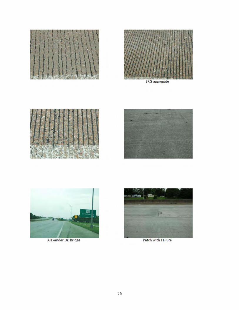
76
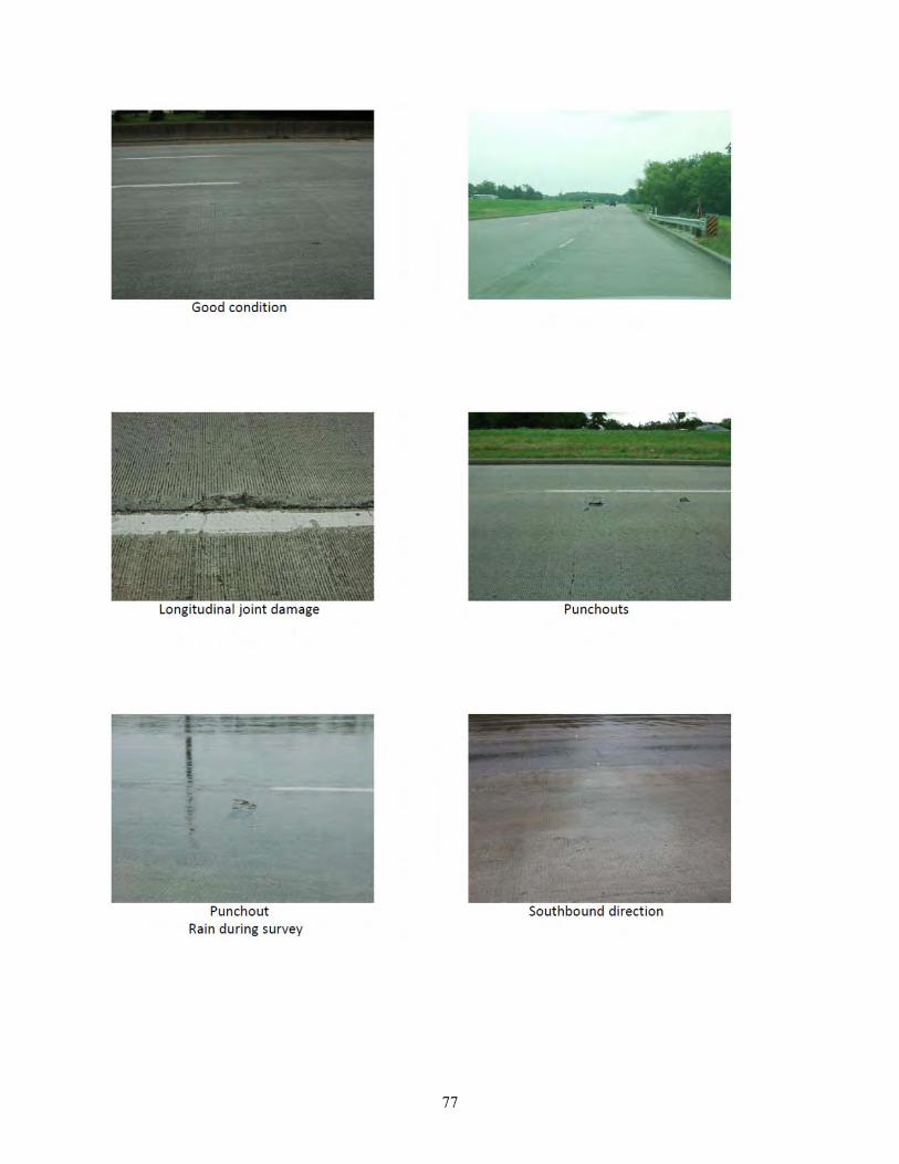
77

78
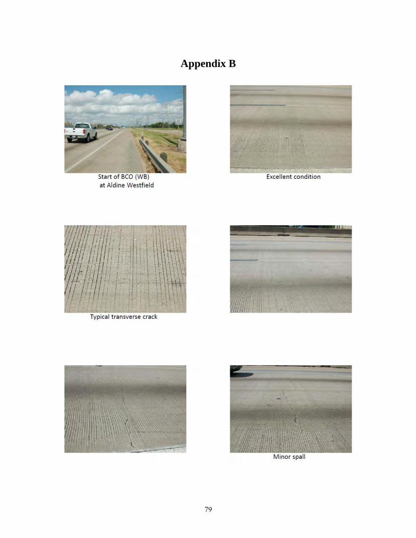
79
Appendix B
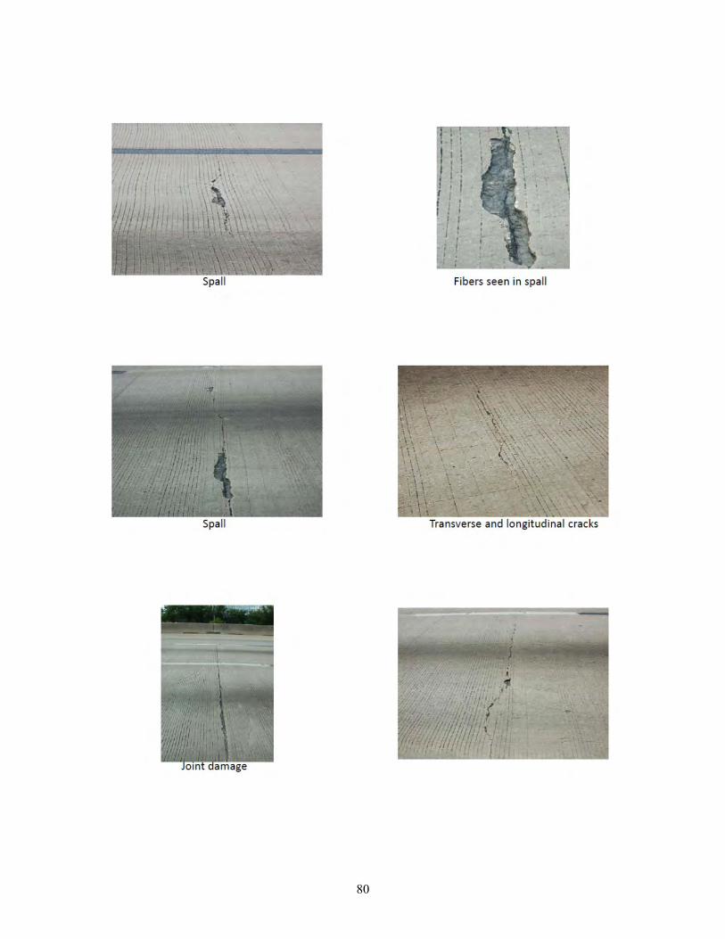
80
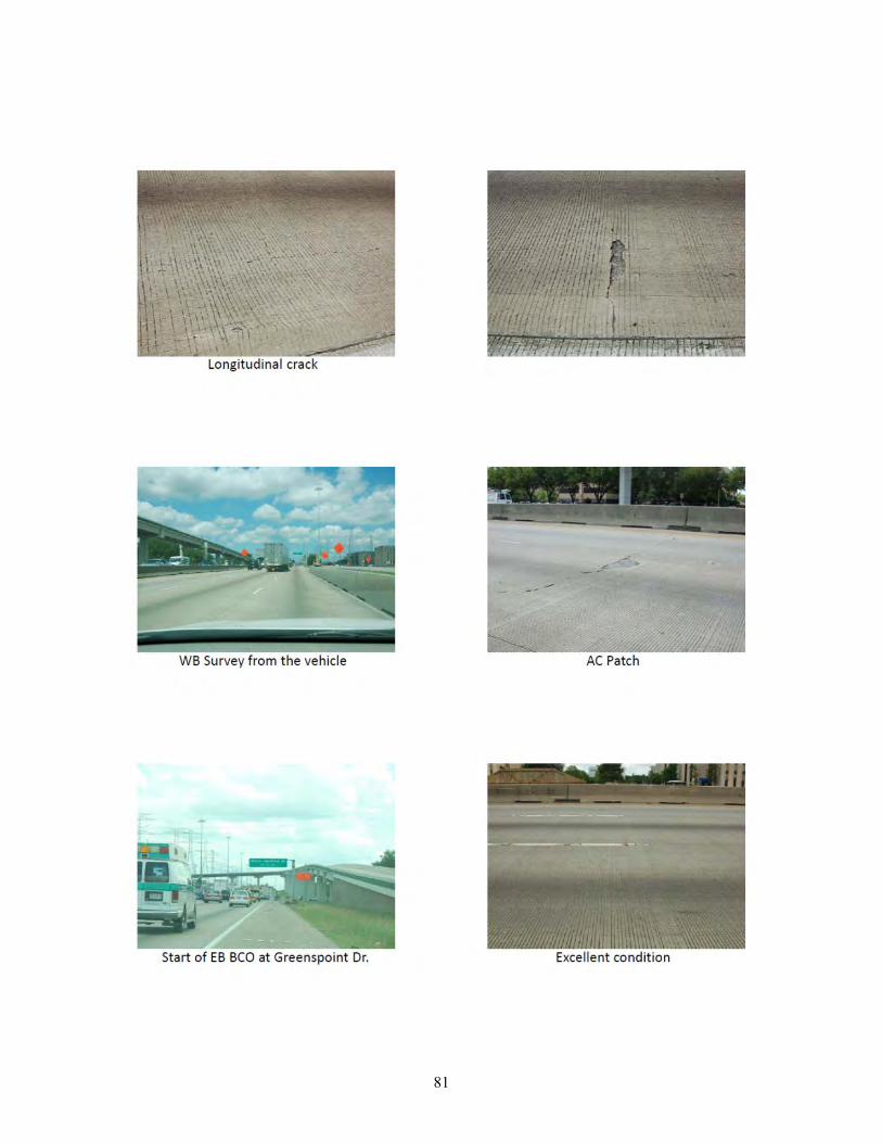
81
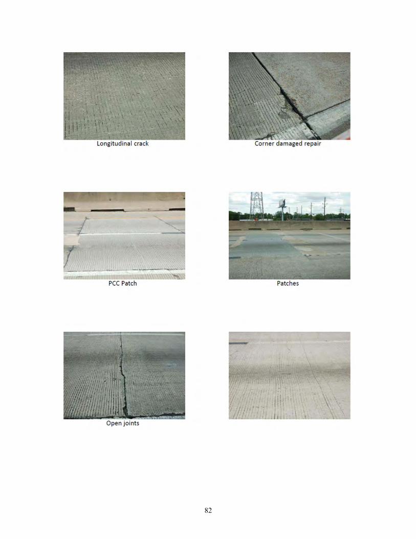
82

83
Appendix C
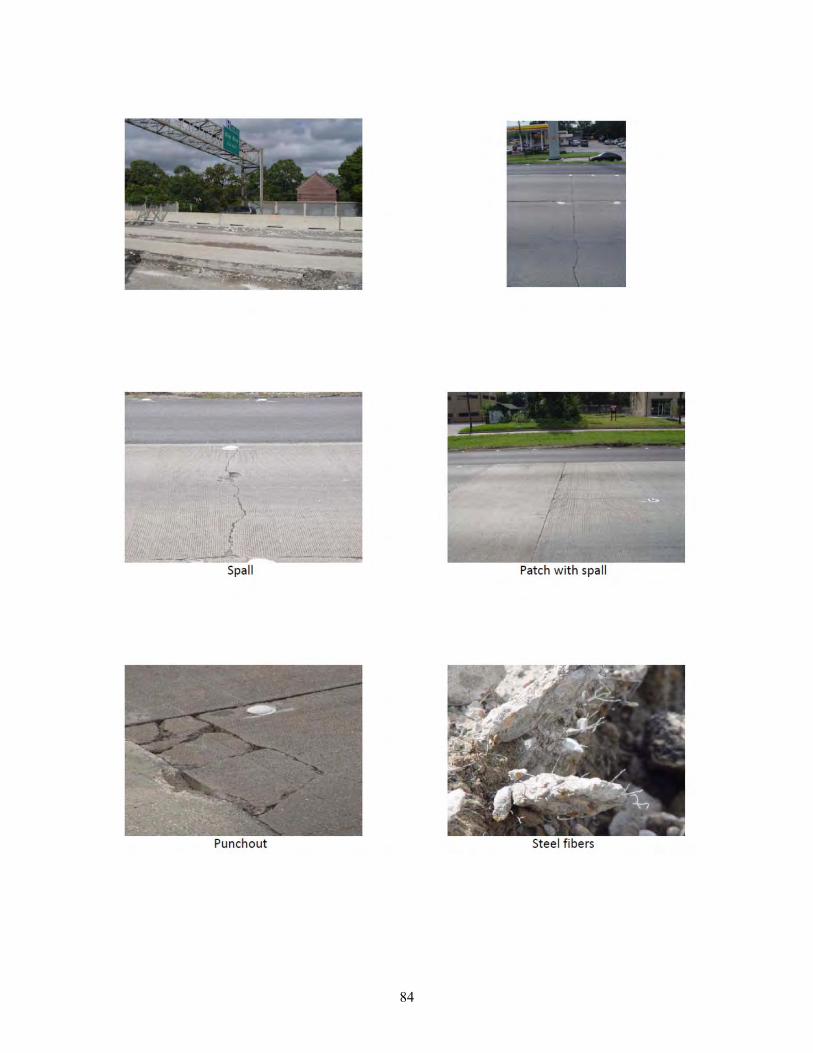
84

85
Appendix D
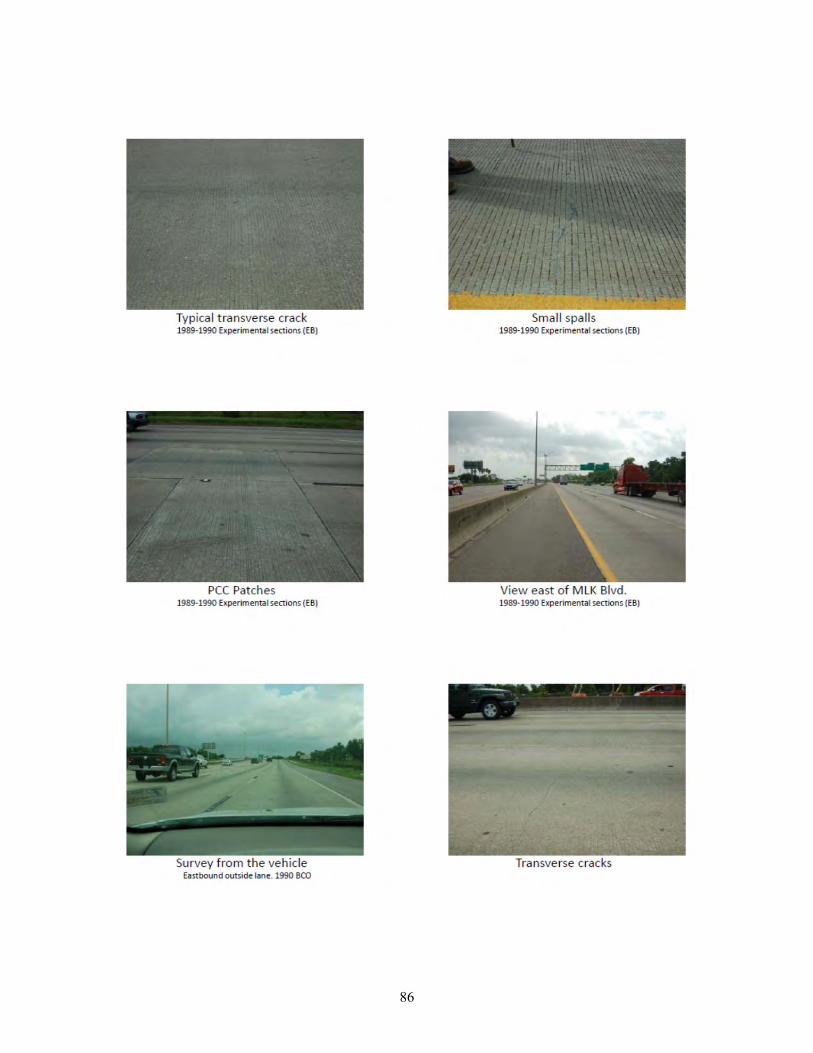
86
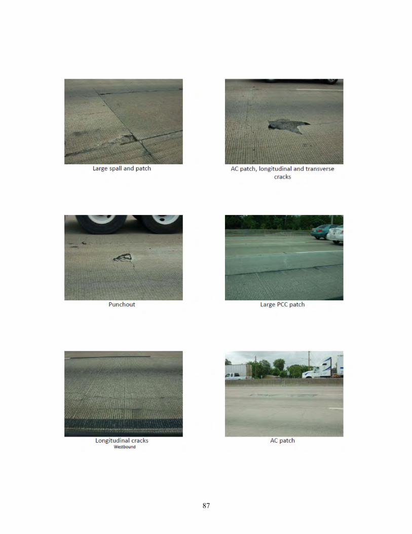
87
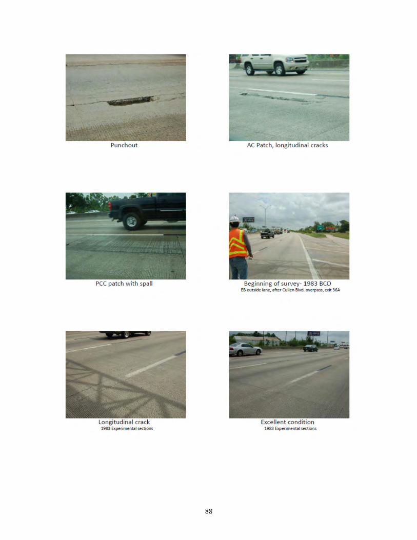
88
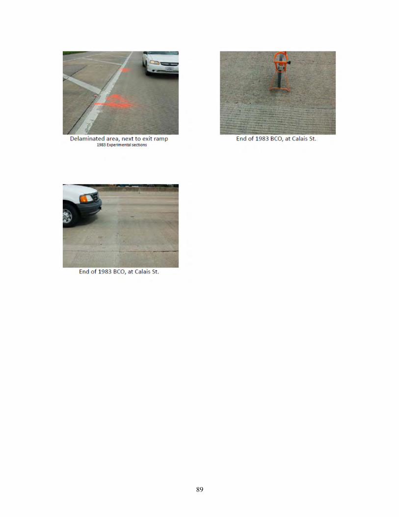
89

90
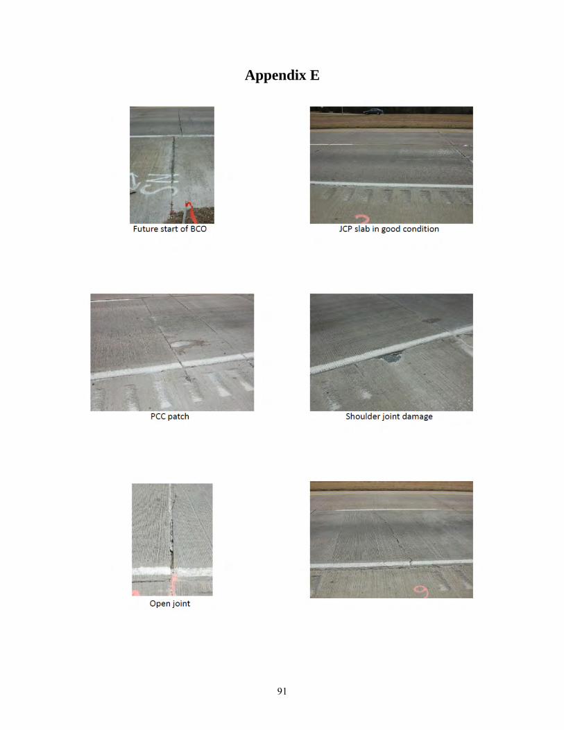
91
Appendix E

92

93

94
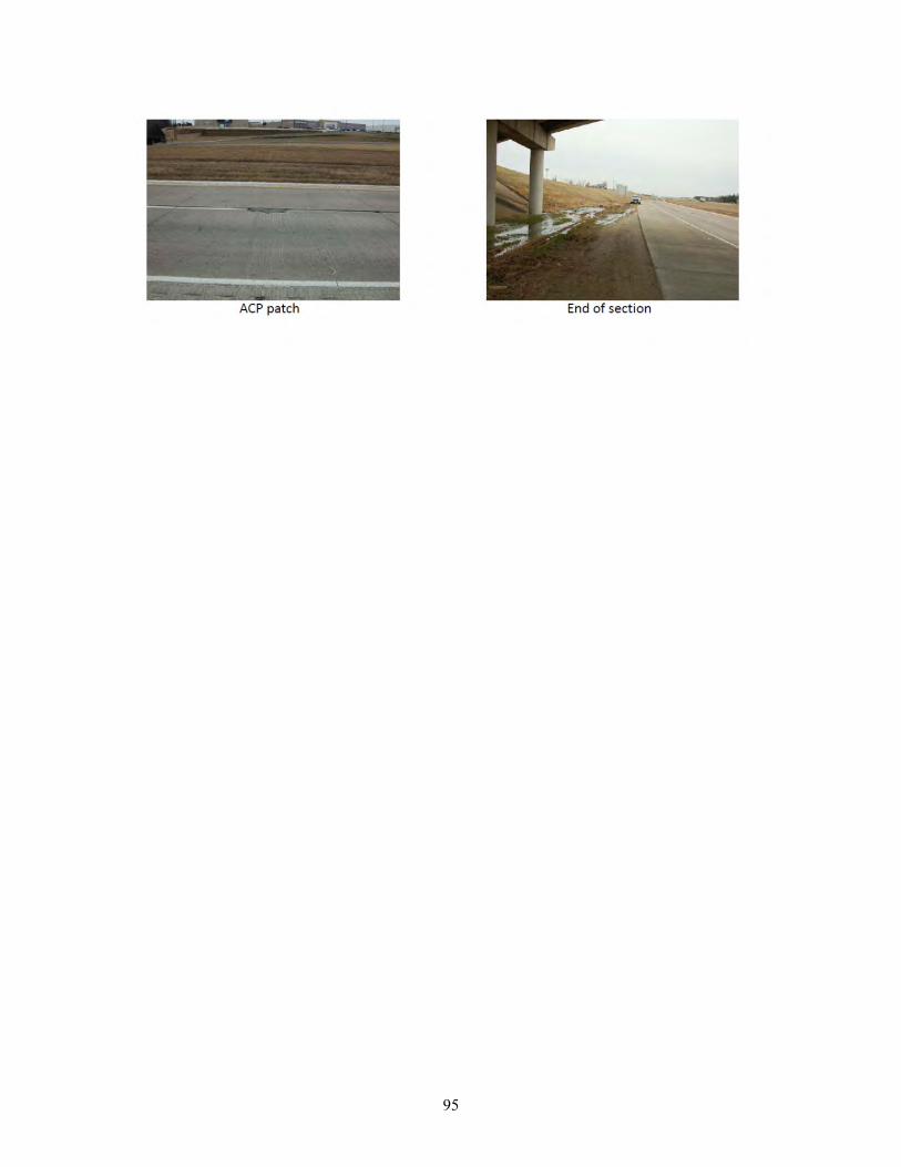
95

96
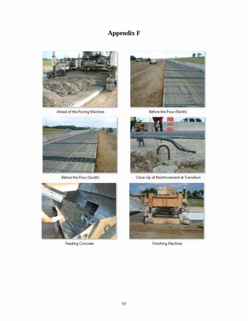
97
Appendix F

98
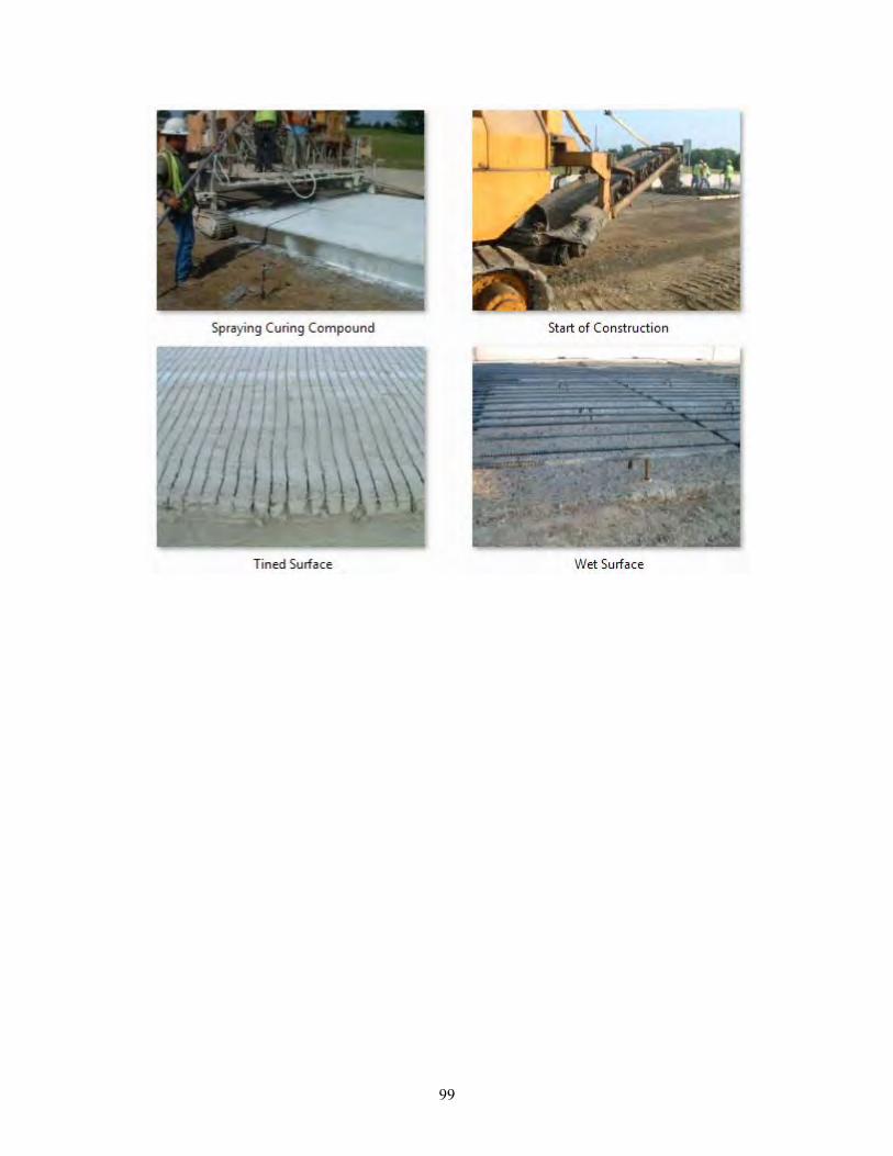
99

100
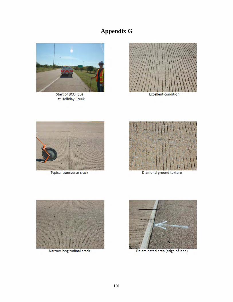
101
Appendix G

102
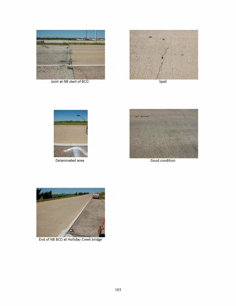
103

104
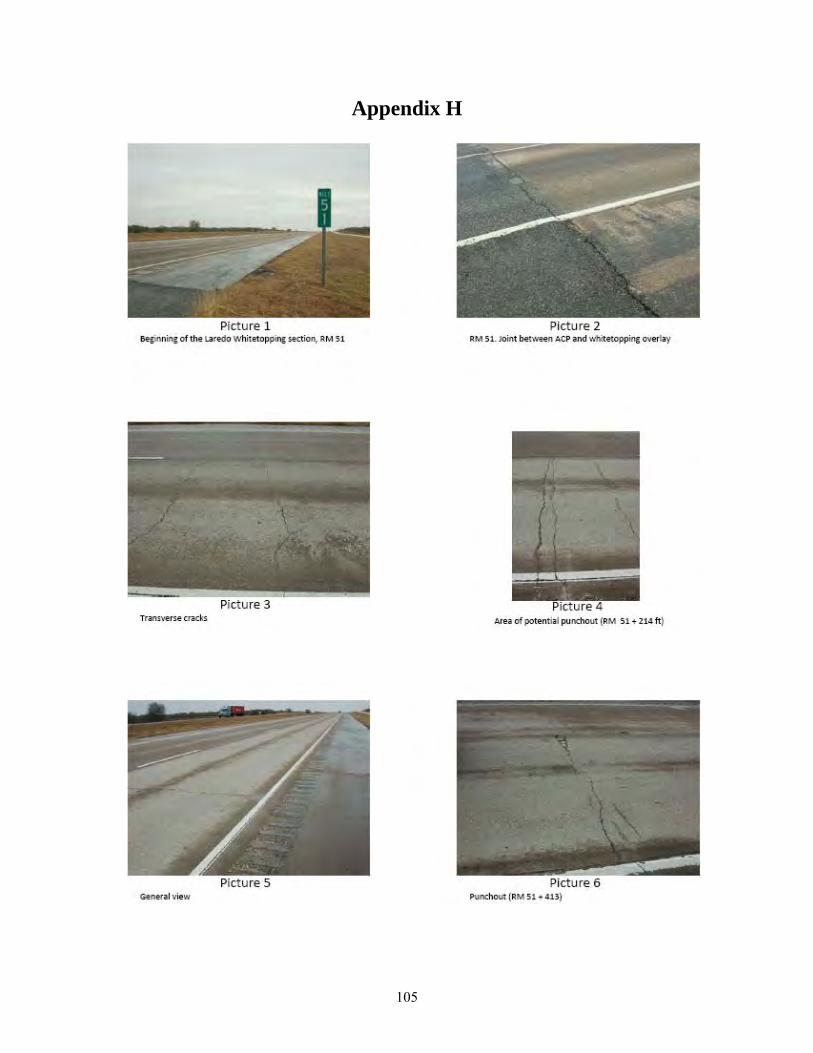
105
Appendix H

106
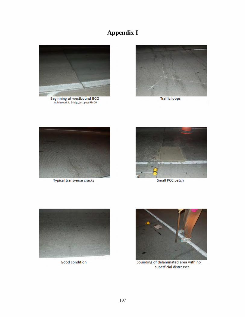
107
Appendix I
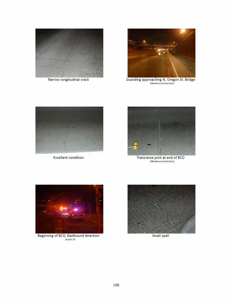
108
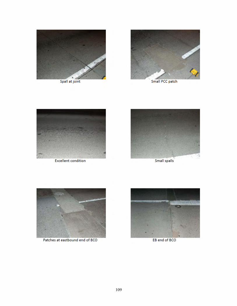
109
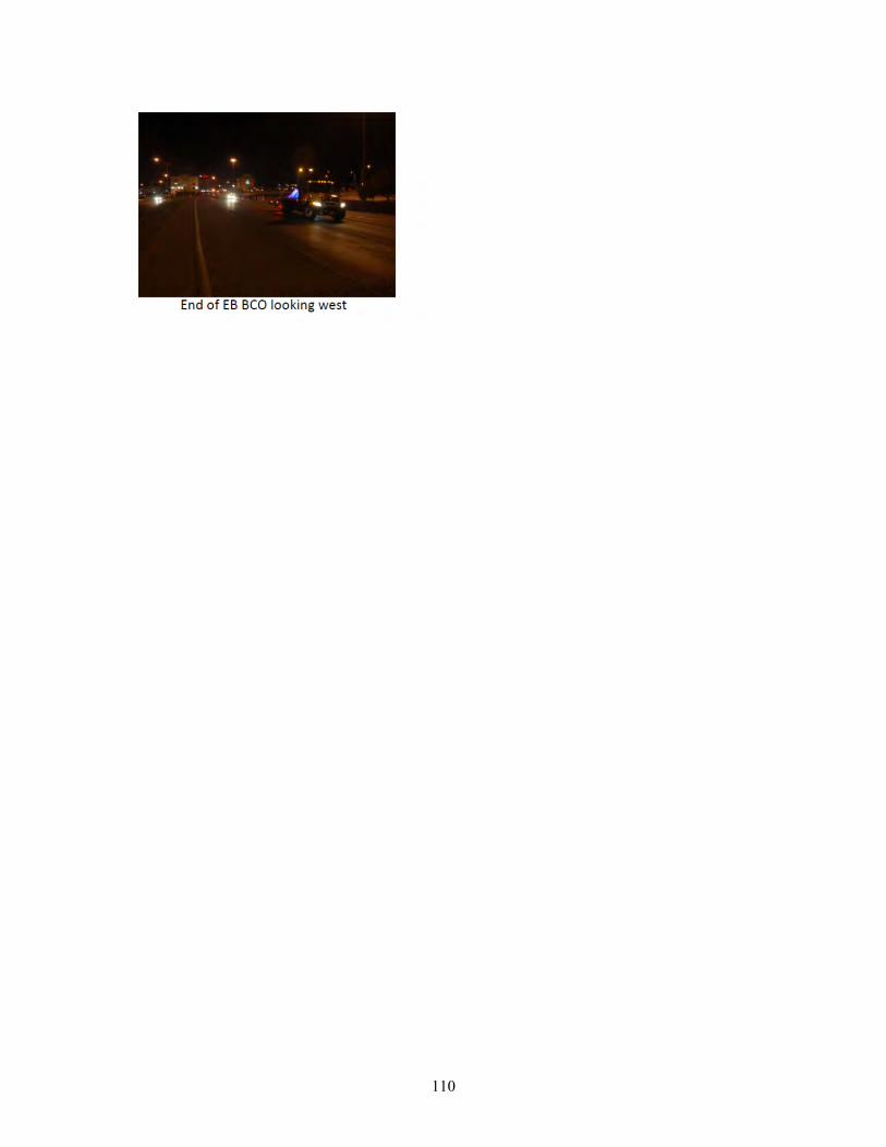
110