materials technology in power generation in the u.k
TRANSCRIPT

Review Paper
Materials Technology in Power Generation in the U.K.
L. M. WYATT
Central Electricity Generating Board, London (Gt. Britain)
(Received January 4, 1971)
CONTENTS
1. Introduction 2. Power generation 3. The reactor core
3.1. The Magnox reactor 3.1.1. Growth in ~-uranium metal 3.1.2. Swelling of uranium 3.1.3. The Magnox can
3.2. The advanced gas cooled reactor (AGR) 3.2.1. Thermal expansion effects 3.2.2. Fission gas release from uranium oxide 3.2.3. The stainless steel AGR can
3.3. High temperature reactor (HTR) 3.3.1. Manufacture of HTR fuel
4. Reactor circuit effects
5. The boiler 5.1. Environmental attack 5.2. Resistance to imposed stresses
6. Steampipes 7. The turbine
7.1. Discs, shafts and casings 7.2. Blading 7.3. Other turbine components
8. The condenser 9. The generator
10. The transformer References
1. INTRODUCTION
The variety of materials used in conventional elec- trical generation and transmission is comparatively small. The materials consist mainly of steels for the stressed components, copper (or aluminium) for conductors and organic compositions or ceramics for insulators.
The introduction of nuclear generation has sig- nificantly widened the range of materials. Reactor cores include the fissile and fertile metals, uranium, plutonium and thorium or their oxides or carbides; materials of low neutron absorption, magnesium and zirconium; moderators such as graphite; neu- tron absorbers, boron, hafnium and the rare earths ; and heat transfer media such as carbon dioxide, helium and sodium.
Materials are supplied to specifications which dif- fer not only internationally but between organi- sations in the same country. For simplicity materials are referred to in this text by short descriptive titles which are listed together with the complete analysis
and application of each material in Tables 1, 2 and 3. Items of plant manufactured from these materials
may be subjected to very severe conditions of stress, temperature and environment and may be very large in size or else present in very large numbers. All components except fuels have very long lives, over 100,000 hours operating or 30 years life and periods in the region of two years between overhauls.
Capital is a major item, contributing in the case of a modern nuclear station approximately 70 ~ of the cost of generation, and 40 ~ in the case of an equivalent conventional station. This in itself makes reliability the most important parameter, since the running cost of a 660 MW unit is of the order of £15,000 per day.
Next in importance comes fuel cost which is controlled by maximum cycle temperature, and lastly, but not to be neglected, the wages of the oper- ating staff.
The criteria which govern the choice of materials and fabrication processes for electrical generation are therefore first, reliability; second, cost; and
Materials Science and Engineering American Society for Metals, Metals Park, Ohio, and Elsevier Sequoia S.A., Lausanne-Printed in the Netherlands

238 L.M. WYATT
third, the capacity to resist high temperatures and stresses. The task of the materials technologist is to optimise these conflicting requirements.
TABLE 1 : BOILER MATERIALS
Steel type Typical chemical composition (%)
C Mn Si Ni Cr Mo V Nb Ti Cu Al B
Application
Carbon Carbon manganese Cr-Mn-Mn-V (Ducol W.30) Carbon
1 Cr-~ M~c 2¼ Cr-1 Mo 9 Cr-I Mo 12 Cr-Mo-V ½ Cr-Mo-V 18 Cr-Ni-Nb (AISI 347) 18 Cr-Ni-Ti (AISI 321) 17 Cr-Ni-Mo (AISI 316) Esshete 1250 Ificoloy alloy 800
20 Cr-25 Ni-Nb
0.20 0.9 0.25 • 0.20 1 .25 0.25 0.15 1.25 0.25 0.6 0.25
0.12 0.5 0.3 0.15 1.0 0.3 0.1 0.5 0.3 1.0 0.5 0.1 0.5 0.3 2.25 1.0 0.1 0.5 0.7 9.0 1.0 0.2 0.5 0.5 12.0 1.0 0.1 0.5 0.3 0.5 0.5 0.08 1.5 0.3 12.0 18.0
0.1
0.3 0.25
1.0
0.08 1.5 0.3 12.0 18.0 0.5
0.08 1.5 0.3 13.0 17.0 2.5
0.1 6.0 0.5 10.5 15.0 1.0 0.25 1.0 0.1 1.5 1.0 30 to 19 to 0.15/ 0 .75 0.15/ max. max. max. 35 23 0.6 max. 0.6 0.2 0.7 0.6 25.0 20.0 0.7
0.005
Boiler drums Boiler drums Boiler drums; by pass vessels
Boiler tubing Boiler tubing Superheater tubing, headers Superheater tubing, headers Superheater/reheat, er tubing Superheater/reheater tubing Steam pipe Superheater tubing, steam pipe
Superheater tubing
Superheater/reheater tubing, steam pipe Superheater tubing, steam pipe Superheater tubing
AGR fuel element can.
TABLE 3: TUBES FOR CONDENSERS/FEEDWATER HEATERS
Material Typical chemical composition (%)
Cu Zn Sn Ni Al Mn Fe As Ti
Application
Commercial brass Admiralty mixture Aluminium brass
Cupro-nickels
Titanium
70 Bal. 70 Bal. 1.25 76 Bal. 2 Bal. 30 2 2 Bal. 30 1 1 Bal. 10 1 1
C Mn Si Mo B
0.4 0.4 0.4
Condensers Condensers Condensers
Condensers
99 Condensers
Carbon steel
Fortiweld (low carbon) steel
0.12 0.6 0.25 max. 0.06 0.6 0.25 to 0.10
0.5 0.003
Feedwater heaters
Feedwater heaters
Mater. Sci. Eng., 7 (1971) 237-267

r,
/4
<
o o
' o o o o o o ~ o o o o o o o
z ~
o o
o~ ~ o ~ ~ -
~ o o
o ~ e,i
o . o .
eq c5
o o c 5
c 5 ~
0 ~ ee5 tt3 ttq ~ o c 5 c5
• --; c s , - J 06
c5 ~ c 5 o ~ c~
Mater. Sci. Eng., 7 ( 1 9 7 1 ) 2 3 7 267
240 L.M. WYATT
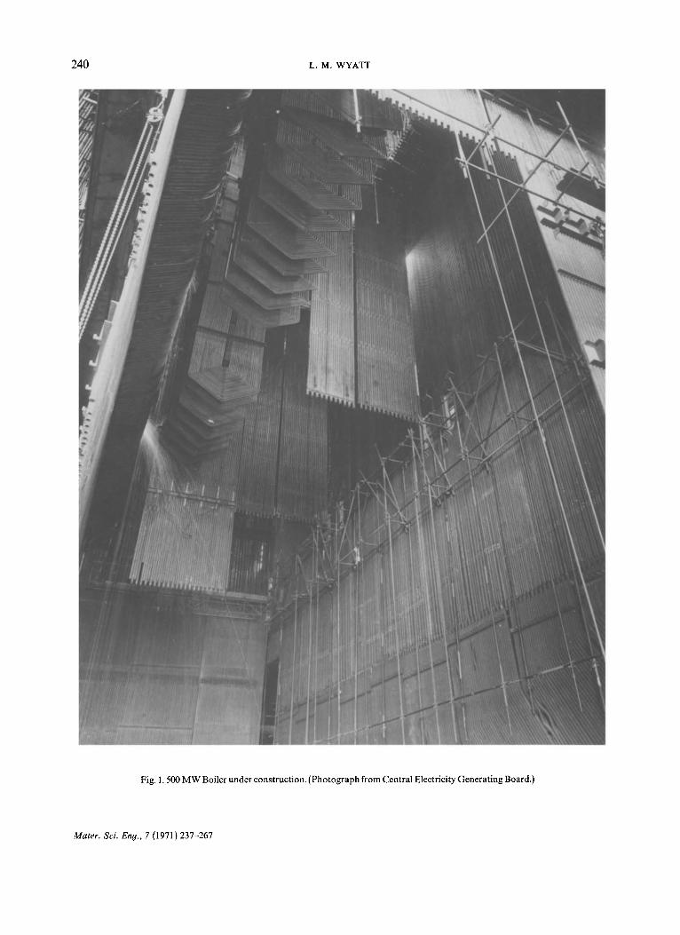
Fig. 1. 500 MW Boiler under construction. (Photograph from Central Electricity Generating Board.)
Mater. Sci. Eng., 7 (1971) 237-267

MATERIALS TECHNOLOGY IN POWER GENERATION 241
2. POWER GENERATION
Generating plant can be steam, gas turbine, diesel or hydro. Steam generating plant operates on the same basic principles whether nuclear or fossil fuelled. There is firstly the heat source. This is either a combustion chamber in which coal, oil or
gas is burned, or a reactor core, a lattice of rods of fissile and fertile materials, usually interspersed in a moderator.
Heat generated by combustion, or nuclear fission, is applied directly or via a primary coolant to high pressure water which is contained in the boiler (or heat exchanger) (Fig. 1).
A B i ! .... :i;ii i~i~iiiil . . . . . . . . . . ~;~ ~ c
Fig. 2. 500 MW Turbine showing high (A), intermediate (B) andJow-pressure (C) stages. (Photograph from AE! Turbine-Generators Ltd.)
n r
Fig. 3. 500 MW Generator. ( Photograph from AEI Turbine-Generators Ltd.)
Mater. Sci. Eng., 7 (1971)237 267

242 L.M. WYATT
The water is heated in the economiser, converted to steam in the evaporator, and superheated in the superheater--three component parts of the boiler. The steam is transmitted through steam pipes to pass through the high, intermediate and low pres- sure stages of a turbine (Fig. 2), where it is converted into rotational energy. Between the high pressure and intermediate pressure stages of the turbine the steam is returned to the reheater, a fourth boiler component. On leaving the low pressure stage of the turbine the steam, now at a low temperature and under vacuum, passes into the condenser.
After this the pressure of the condensed water is raised by a series of feed pumps, its temperature is raised by a series of feed heaters and it finally passes back into the economiser.
The rotational energy produced in the turbine is transmitted through shaft and couplings to the generator (Fig. 3), which converts it into electricity.
The relatively low voltage electricity produced by the generator passes along busbars to a transformer where its voltage is raised to that required for econo- mic transmission.
The problems raised have in many cases very similar characteristics throughout the plant, and the account which follows illustrates this by high- lighting the typical problems of each of them.
3. THE REACTOR CORE
The nuclear power programme in the U.K. is based on the gas-cooled reactor system in its various developments: the Magnox reactor, the advanced gas cooled reactor and the high temperature reactor.
The fuel element problems of these reactors will be described as they are typical of those found in most systems.
One feature common to all these reactors is that the basic core structure is provided by a moderator built of graphite blocks, through which are machined vertical channels in which are stacked the fuel ele- ments and through which passes coolant gas.
The graphite stack is restrained on the outside to prevent relative movement of the graphite blocks, but since graphite is strong in compression there is no requirement for an additional in-core structure to support the fuel elements.
3.1. The Magnox reactor
The Magnox reactor channel is approximately 4
Fig. 4. Magnox reactor fuel element. (Photograph from United Kingdom Atomic Energy Authority.)
inches in diameter and 20 feet long and the fuel elements, a typical example of which is shown in Fig. 4, are stacked in this one above the other 1. The weight of the superimposed fuel elements or asym- metry in either temperature or irradiation of the individual fuel element may lead to bending in creep. This bending is restrained by lugs on the fuel element can; it is important to minimise the bending and for this purpose to understand the parameters which cause it, so that it can be controlled. It is also necessary to maintain a smooth uranium surface and prevent significant changes in length.
All these require a knowledge of the phenomenon of growth which is characteristic of uranium irradia- ted at temperatures below 400°C.
3.1.1. Growth in a-uranium metal If fission occurs in a single crystal of uranium
within the temperature range described it changes in shape as shown diagrammatically in Fig. 52, in- creasing in length in the [010] direction, contracting in length in the [100] direction and remaining di- mensionally stable in the [001] direction. This phe- nomenon is the result of the condensation of vacan- cies and interstitials produced during the fission process in an anisotropic crystal, and the formation thereby of dislocation loops (Fig. 6). No significant density change occurs. Growth is highly tempera- ture dependent, increasing approximately linearly as the temperature is lowered below 500°C. The percentage elongation per atomic percent burn up, measured in the [010] direction, is negligible at 500°C but is 11000 at -196°C 3. Growth can also
Mater. Sci. Eng., 7 (1971) 237-267

MATERIALS TECHNOLOGY IN POWER GENERATION 243
GROWTH OF SINGLE CRYSTAL
O10 OO1 OIO IOO O 1 0
GP, OWTH WITH WRINKLING
o r o I o o O l O IOO
C O A R S E W R I N K L I N G
kl I I I I I I I.I I I I I I I ~ ~ FINE WPq NKLING
Fig. 5. Diagrammat ic representa t ion of growth.
t t
m
D
Fig. 6. Deformat ion and dis locat ion loops created by extra layers of a toms ab cd and missing layers ef, gh. (After Buckley3.)
occur as the result of thermal cycling uranium because of the mismatches in thermal expansion between adjacent grains which result from the anisotropy of the uranium crystal 4.
These processes have three results of significance to reactor technology. Firstly, uranium which has any preferred orientation will increase in dimen- sions in that direction which contains more than the normal proportion of crystals orientated in the [010] direction.
Secondly, any area of the surface of the uranium containing a crystal grain with its [010] direction perpendicular to the surface will rise and any area containing a crystal grain with its [100] direction perpendicular to the surface will sink. The surface will therefore roughen, and the effect can be sub-
stantial in highly irradiated coarse grained uranium (Fig. 7) 5 .
The third effect is a decrease in creep resistance. If two adjacent crystals are so orientated that the [010] direction in one is parallel to the [1100] direc- tion in the other, the growth process will force each of them to strain plastically so that they are compa- tible in size at the interface. Any additional force however small applied in the grain boundary plane will therefore cause creep or plastic flow and this flow will be proportional to the magnitude of the applied force. The anisotropy of the uranium gives rise to enhanced creep under irradiation or thermal cycling. There is little that can be done to reduce irradiation creep in s-uranium and its effect on the bending of the bar must be taken account of in design and opera- tion.
The prevention of bending, length, change and surface roughening as a result of irradiation is however highly important and fuel elements must be produced with a fine grain size and the minimum preferred orientation.
If uranium is cooled rapidly from the fi or 1' phase, recrystallisation occurs during transformation. In pure uranium the grains grow to substantial size, but fl and ? soluble additions such as aluminium and iron modify the nucleation processes occurring during transformation and facilitate the production of a fine grain size by quenching. In practice, this is carried out by passing the uranium bar through an induction coil and then through a water spray.
It is not possible to produce a material with absolutely random orientation for two reasons 6. The first is that s-uranium crystals grow preferen- tially in the [010] direction along the temperature gradient during transformation from the fl phase and the second that the original orientation tends to persist after heat treatment. It is therefore impossi- ble to produce a random orientation in a material in which a substantial preferred orientation has previously been produced, for example, by mecha- nical working, but the cast material normally used is itself substantially randomly orientated and cast and heat treated material has very little orientation.
3.1.2. Swellin9 of uranium The second process needing control in uranium
metal under irradiation is swelling 7. The fission process converts one uranium atom into two atoms, the combined atomic weights of which are slightly less than that of the parent uranium, together with a number of light particles. The bulk of these fission
Mater. Sci. Eng., 7 (1971)237-267

244 L.M. WYATT
Fig. 7. Irradiated uranium bar of varying grain size (a) composite photograph of bar (b) micro-section of light wrinkling showing small grain size (c) micro-section of coarse wrinkling showing large grain size. (After Grainger and MclntoshS.)

MATERIALS TECHNOLOGY IN POWER GENERATION 245
products are solids but roughly 1 0 ~ are the inert gases krypton and xenon. These gases diffuse in the ,o uranium until they coalesce into bubbles which grow is size by the diffusion of further inert gas atoms (Fig. 8) 9. When these bubbles are small in ~ 30 size their increase in diameter is controlled by the surface tension of uranium ~°. As they increase in size the effect of surface tension diminishes and the ~ 2 o restraining force is the creep strength of the ura- nium 11 - ~ 3. If the inert gas mixture can be persuaded to distribute itself between a very large number of ,o bubbles, the overall swelling will be much less than that which would take place if there were only a few relatively large bubbles. Swelling is highly tempera- o ture dependent, there being a general increase with temperature on which is superimposed a break- away condition of high swelling which is rating and temperature dependent.
I I I I 0 1 0 0 0 2 0 0 0 3 0 0 0 4 0 0 0 SO00
LOCAL IRRADIATION M W D / r e
Fig. 9. Volume changes of fuel elements in a typical reactor in the temperature range 390 + 20°C.
because of the need to maintain the integrity of the can which prevents the ingress of the oxidising coolant, and the egress of radioactive fission pro- ducts. The magnesium alloy cans used in the Mag- nox reactors have little inherent strength at opera- ting temperatures and will therefore substantially follow the changes in dimensions of the uranium bar. Fortunately, magnesium is a very ductile metal and if correctly manufactured can accommodate very considerable deformation without cracking.
The optimum structure is achieved by a metal working and heat treatment process designed to produce a fine grain size in the can. When magne- sium (in common with many other metals) is subjec- ted to creep or fatigue, vacancies are produced at the grain boundaries which coalesce to form cavities (F ig . 10) 17 . As this progresses the cavities link up
Fig. 8. Gas bu[pbles formed by irradiation and subsequent annealing of uranium. (After Eldredg.)
Fortunately the addition of aluminium and iron to control transformation during heat treatment and give a fine grain size produces a structure with a very large number of fine UA12/Fe particles which together with the aluminium in solution promote the formation of a large number of very small bubbles rather than a few large ones 14. This uranium is extremely resistant to swelling is (Fig. 916).
3.1.3. The Magnox can Clearly, large changes in diameter or length of the
uranium bar are to be avoided in themselves but they are particularly important in fuel elements
Fig. 10. Voids formed at grain boundaries of coarse grained magnox can by strain at low temperature. (After Eldred".)
Mater. Sci. Eng., 7 (1971) 237-267

246 L.M. WYATT
and form continuous leakage paths along the grain boundaries. If the grain size is large so that the whole thickness of the can is effectively composed of one grain, these linked up cavities can form a con- tinuous path through the wall permitting the ingress of coolant and oxidation of the uranium. This can occur at low reactor temperatures where the rela- tively low ductility of the magnesium and growth of the uranium may lead to failure of the can by cavitation. It is overcome by producing a bar with a fine random grain size and a can with a fine grain size which at the low operating temperatures where growth presents a problem persists through the life of the fuel elements.
At the higher reactor temperatures at which grain growth occurs in Magnox even the large grain size material is highly ductile; however, at the highest irradiations localised swelling can cause stretching of the can sufficient to lead to failure.
Magnesium and uranium are completely compa- tible, being immiscible at all temperatures. There- fore there is no possibility of any uranium diffusing through the can. Plutonium which is formed during service in the reactor is, however, readily soluble in pure magnesium and will diffuse through (Fig. 11) 18-21. This in itself would not be dangerous
z i.-
0 2 J o
'o x
#
1 0 0 o ~ X I o o o
I00
\
\o \
O \
\ (*)
\
o k \
\ 0
0 IO 2 0 3 0 4 0 5 0 60 D E P T H BELOW INNER SURFACE~ /urn
Fig. 11. Diffusion of plutonium through magnesium alloys (a) containing aluminium (b) aluminium free. (After Pearce~8.)
because the plutonium content of the rod builds up only slowly during irradiation; only a small pro- portion of this would actually diffuse through the can. It would however interfere with apparatus designed to isolate failed cans by detecting fission products in the coolant stream and must therefore be prevented. This is done by using a magnesium alloy (Magnox A1 80) containing about a half per- centage of aluminium; when plutonium is trans- ferred from the uranium to the can it reacts with the aluminium to form Pu A13 which does no diffuse through the magnesium and therefore remains on the inner surface.
Magnox is an excellent canning material, but its range of operating temperature is restricted to about 500°C by its melting point and tendency to soften. This operating temperature is very well matched by the tendency of uranium to swell, and the need to avoid the dimensional changes that would result from extensive cycling of this fuel across the ~/fl phase boundary.
A change, both in fuel and in canning material, is therefore required for a reactor designed to gener- ate heat at a higher temperature and heat rating.
3.2. The advanced gas cooled reactor (AGR)
The AGR, which is the logical next development of the Magnox reactor, uses an oxide fuel and a stainless steel can. Uranium oxide retains its mechanical strength up to about 1200°C but is extremely brittle and difficult to produce by casting. It is therefore manufactured by pressing and sinter- ing into solid or annular pellets which are stacked inside a steel can. The neutron absorption cross section of steel is substantially higher than that of magnesium and it is essential to keep volume and thickness to the minimum. A typical AGR fuel element is shown in Fig. 12. Each fuel pin is about 3 feet long, 0.57 inch in diameter and contains hollow pellets of about 0.2 inch bore in a can of 0.015 inch thickness. There are 36 of these fuel pins in a cluster housed within a graphite sleeve.
3.2.1. Thermal expansion effects Relative diameter changes between the oxide and
the can impose strains on the can which if continued indefinitely cause failure by fatigue 22. The mecha- nism is as follows:
An increase in power leads to an increase in dia- meter of the oxide pellet. This puts a tensile stress on the can at constant temperature and the can is
Mater. Sci. Eng., 7 (1971) 237-267

MATERIALS TECHNOLOGY IN POWER GENERATION 247
The straining effect is enhanced by cracking of the oxide caused by the thermal stresses, the cracks tending to localise the strain in the adjacent canning material. This effect is reduced by the use of annular pellets.
3.2.2. Fission 9as release from uranium oxide Fisssion gas can cause swelling of the oxide fuel
but the most important effect is its diffusion to the surface of the pellet (which occurs only to a very slight extent with metal fuel) which generates a pressure inside the can 23'24. Clearly, this pressure cannot be allowed to rise to a level where can failure would occur even in a hypothetical transient. It is therefore important to reduce the diffusion of fission product gas as far as possible and this can be done in two ways.
Firstly diffusion occurs more readily in oxide not compacted and sintered to a high density; secondly the self diffusion coefficient which also controls the inert gas diffusion is an order of magnitude lower in stoichiometric uranium oxide--UO2 than in the non-stoichiometric form UO2.2. It is therefore essential to manufacture only stoichiometric UO2 and this can be achieved by reducing the powder, or the preformed pellet, in hydrogen under closely controlled conditions.
Fig. 12. Typical AGR fuel element. (Photograph from United Kingdom Atomic Energy Authority.)
therefore stretched. When power is reduced the oxide contracts and the coolant pressure forces the can to creep down. An increase in power re-imposes a tensile strain and if the cycle is repeated sufficiently often the can may fail by fatigue. If an increase or decrease in can temperature accompanies the increa- se or decrease in power the effect is reduced parti- cularly when a canning material with a coefficient of thermal expansion greater than that of uranium oxide is used. Theoretically, it is possible to operate individual fuel elements without imposing any fatigue strain on the can; in practice this is impossi- ble with thousands of fuel elements all at different levels of temperature and power.
3.2.3. The stainless steel AGR can The operating temperature of up to 4, 810°C im-
posed on an AGR fuel element is limited partly by the mechanical properties of the can, but also by its tendency to oxidise in the CO2 atmosphere. The combination of strength and resistance to oxidation by CO2 at high temperatures with a high coefficient of thermal expansion and the minimum possible neutron absorption favours the choice of an austeni- tic steel as a canning material.
For the AGR the rate of oxidation is reduced by raising the chromium content to 2 0 ~ compared with the 1 8 ~ of the normal austenitic steel and compensating for the effect of this on ductility associated with the formation of sigma phase during long term heating by increasing the nickel content to
8/o, additional 2 5 ~ compared with the normal o/. creep strength is provided by the addition of 0.5 ~o niobium. This steel has excellent mechanical prop- erties, and if close attention is paid to the main- tenance of the optimum grain size and other para- meters it can be shown to have in the manufactured condition ample ductility and strength to accept any strain regime that is likely to be imposed.
Mater. Sci. En#., 7 (1971) 237 267

248 L.M. WYATT
During irradiation, however, a naturally occurring isotope of boron which is present in small a m o u n t s in steel interacts with thermal neutrons to produce helium which substantially reduces the high temper- ature ductility 25 - 2 8 .
This not only makes it impossible to take ad- vantage of the beneficial effects of boron additions but it also requires positive action in the choice of alloying and crucible materials to minimise the content of this element.
Clearly, in cans of wall thickness of only 0.015 inch it is impossible to tolerate inclusions of the size normally occurring in commercial steels. Steel of the requisite quality can be achieved by double vacuum melting. The steel is made in a high fre- quency furnace and then remelted in a consumable arc furnace to remove or disperse the non-metallic inclusions.
3.3. High temperature reactor (HTR)
Fuel based on the coated particle concept for the high temperature reactor 29 differs quite significantly from either of the fuels described previously. The reactor coolant is helium and this permits the use of carbon as a canning material both as a structural material and as an envelope for retaining fission products. The advantages of carbon are firstly a very low neutron capture cross section and secondly strength at very high operating temperatures.
3.3.1. Manufacture of HTR fuel The fuel is made in the form of spherical particles
(Fig. 13) each about 800/~ in diameter coated with layers of carbon and other compatible materials.
The coated spheres are placed either loose or bonded together into a graphite tube which provi- des rigidity and dimensional stability. The bond can be a thin layer of organic material, or more usually a graphite/polymer matrix in which the particles are embedded. The fuel tubes are mounted in moderator blocks (Fig. 14) so that the whole assembly can be removed during refuelling.
The problems of design and manufacture are two-fold 3°. Firstly, it is essential to maintain the integrity of the coated particles during manufacture, handling and operation so that contamination of the coolant by fission products is minimised. Se- condly, it is essential to maintain the dimensions of the compact so that dimensional changes do not cause failure of the graphite tube.
The fuel particles, which may be uranium, ura-
Fig. 13. Spherical particle HTR fuel (a) before (b) after irradiation. (After Shepherd3°.)
nium/plutonium or uranium/thorium, can be made of either oxide or carbide. Oxide particles are made by a process of agglomeration followed by sintering; carbide particles are made by a melting process.
Particle coating is carried out by pyrolytic de- composition of a gas in a fluidised bed. In a common- ly used design of coated particle the first layer is of low density carbon which forms both a reservoir
Mater. Sei. Eng., 7 (1971) 237-267

MATERIALS TECHNOLOGY IN POWER GENERATION 249
i ¸ i i i i i i i i
i, ,J
changing the temperature and composition of the gas from which they are deposited 31.
If the wrong conditions are chosen, the pyro carbon layers tend to contract on to the particle and crack. This results in the escape of fission product gas and when the cracking becomes severe enough the matrix also cracks and may lead to cracking of the tube.
The purpose of the silicon carbide layer is to form a strong member in compression which controls the dimensional changes of the kernel and also acts as a barrier for metallic fission products 32.
A mode of failure which is apparently due to chemical causes is observed at high temperatures in beds of loose particles; this is the so-called Amoeba failure in which the kernels of particles have been observed to migrate into the coating with the even- tual result that the latter is completely penetrated. This effect appears to be associated with the exis- tence of high temperature gradients across the particles (Fig. 15).
4. REACTOR CIRCUIT EFFECTS
!!i . . . . . . . . . . . . . . . . . . . . . i! ~ ~?~ : ii( :i
Fig. 14. HTR fuel tubes contained in graphite moderator block. (After Shepherd3°.)
for fission product gases and a buffer to accommo- date changes in size and shape of the particle and the outer layers. The next layer is of high density carbon, after which comes a layer of silicon carbide and an outer layer of high density carbon. Deposited carbon layers of this type can be highly anisotropic, but the degree of anisotropy can be controlled by
The two requirements of the reactor circuit are that the containing member shall be strong and ductile enough to prevent failure under the influence of gas pressure, and that the integrity of the components of the circuit generally shall not be impaired by the corrosive effect of the coolant gas.
Corrosion has presented a serious problem in carbon steel circuit components of the Magnox reactors 33'34. The amount of penetration has been insufficient to have a direct effect on the strength of any given component, but an indirect effect whereby the increase in dimensions caused by oxidation in crevices leads to component failure by strain has more serious consequences. This can be severe in bolts. Frequently a bolt secures a considerable num- ber of separate components so that the bolt head and the nut may have 10 or more surfaces between them. Oxidation of carbon steels by CO:, occurs as rapidly in crevices as on free surfaces. The bolt thread acts as a notch reducing the effective duc- tility to a very low value. The rate of oxidation is highly temperature dependent, the doubling time being approximately 25°C. It is also pressure depen- dent, increases with increased wetness of the coolant gas and is very strongly influenced by the silicon content of the steel 35'36.
The only really effective countermeasure is to
Mater. Sci. Eng., 7 (1971) 237-267

250 L .M. WYATT
Fig. 15. "Amoeba" type failure of HTR fuel showing migration of core into coating. (After Shepherd3°.)
reduce the temperature of the gas; the rate Of attack on carbon steel is sufficiently small at temperatures below 360°C to present little problem in reactor lifetimes z'33. Fortunately, reactor struc- tures usually have a fair degree of built-in redun- dancy and the failure of a considerable proportion of the bolts in a given reactor can be tolerated.
In the AGR at low temperatures, the problem of resistance to CO2 attack is simply one of choosing the correct temperature at which carbon steel gives place to chrome and higher alloy steels. An interest- ing aspect is the effect of silicon on the 9 Cr-1 Mo steels. Figure 1637 shows that this is quite as impor-
.9
.B
.7
.c 0 0 0 .6
E
~ .5 _Z
0 I- .4 I"
.3
x x
i i i i i i i i .I . 2 . 3 , 4 . 5 . 6 .7 -8
O/o SILICON
Fig. 16. Oxidation of 9 Cr-1 Mo Steels at 500°C in CO 2 atmos- phere.
Mater. Sei. Eng., 7 (1971) 237 267

MATERIALS TECHNOLOGY IN POWER GENERATION 251
tant to these steels as for the carbon steels at lower temperatures. Chromium additions of the order of 12 ~o and above mask this beneficial effect of silicon.
In the high temperature areas of the AGR, austenitic steels must be used.
Circuit problems of the HTR which might be expected to be of a simpler nature are in some ways more complex than those of the lower temper- ature carbon dioxide cooled reactors 38. The com- plexities arise from the impurities present in the helium in small amounts. The reactor circuit will certainly contain hydrogen by diffusion through the boiler tubes and in addition there will be leakage of water both at a relatively constant rate and in sudden bursts. The water will react with the graphite and produce an atmosphere containing hydrogen, methane, carbon monoxide, carbon dioxide and possibly residual water. The coolant atmosphere can therefore vary from oxidising to carburising. The effect on ferritic steels at their operating temperatures is negligible but the combination of carburising and oxidising gas can lead to rapid inter-granular penetrations of austenitic steels at temperatures of 700°C and above. Additionally the high strength alloys creep at rates approximately three times greater than those in air in a helium atmosphere. It is not clear whether this is due to the absence of some protective action normally provi- ded by the air environment such as internal oxida- tion or nitriding or is the result of inter-granular penetration by the carburising atmosphere.
Clearly, however, the effects of these atmospheres will require careful study for which data from long time corrosion tests are required.
5.1. Environmental attack
The resistance to attack of boiler materials depends on the temperature of operation, the composition of the steel and the nature of the environment.
In pure, oxygen-free water at tempertures above 230°C and below 567°C, and at pH greater than 8 (and in CO2 at low temperatures), a stable imper- vious magnetite Fe30 4 film is formed (Fig. 17). In more oxidising conditions, haematite, which is less resistant but still confers appreciable protection, is formed at temperatures below 567°C. At tempera- tures above 567°C wfistite, FeO which confers little protection, is formed.
Oxidation at all temperatures is reduced by the addition of certain alloying elements, the most effective of which is chromium.
At high temperatures the oxidation rate increases with small additions of chromium up to 2 O//o but for larger additions in the range of 2-15 o~ (Fe, Cr).~O4
¸ ,ioi+i
5. THE BOILER
The materials problems of the boiler are twofold. First, the material of the tubes, headers and pipes must resist environmental attack by the contained water and steam, and by the external gases, prod- ucts of combustion in the case of fossil fuelled boilers, and CO2 or helium at varying degrees of purity in the case of nuclear boilers.
Second, the materials must resist the stresses imposed during operation by the pressure of the working fluid, by differential temperatures during operation, by temperature gradients introduced during welding and heat treatment, and by hydraulic pressure during testing.
ili ̧ ii i li i l i i ~
(b) . . . . lo~,,
Fig. 17. Compar ison between magnetite film grown in power station and in the laboratory. (a) Boiler tube after 10,000 hours in service. (b) Mild steel oxidised for 250 hours at 300~C in 15% N a O H soln. NaOH promotes the formation of a thick dense
magneti te film.
Mater. Sci. Eng.. 7 (1971) 237 267
252 L . M . WYATT
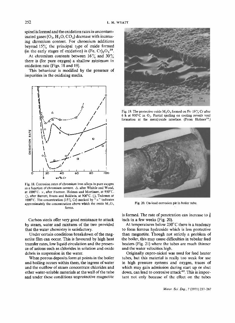
spinel is formed and the oxidation rates in uncontam- inated gases (02, H20, CO2) decrease with increas- ing chromium content. For chromium additions beyond 15~ the principal type of oxide formed (in the early stages of oxidation) is (Fe, C r ) 2 0 3 3 9 .
At chromium contents between 16~o and 30~ there is (for pure oxygen) a shallow minimum in oxidation rate (Figs. 18 and 19).
This behaviour is modified by the presence of impurities in the oxidising media.
I I I I I I 1 I
o /
: / , I
i: " ,,' /
o x /
~ \x I / o
\ o _ 1 ° f f I I I I f I I
O 20 4 0 60 8 0 I O0
X wt°lo Cr
Fig. 18. Corrosion rates of chromium iron alloys in pure oxygen as a function of chromium content. A, after Whittle and Wood, at 1000°C. x, after Footner, Holmes and Mortimer, at 950°C. (3, after Barrett, Evans and Baldwin, at 900°C. Fq, Tedomm at 1000°C. The concentration (15 ~ Cr) marked by " x " indicates approximately the concentration above which the oxide M20 a
forms.
Carbon steels offer very good resistance to attack by steam, water and mixtures of the two provided that the water chemistry is satisfactory.
Under certain conditions breakdown of the mag- netite film can occur. This is favoured by high heat transfer rates, low liquid circulation and the presen- ce of anions such as chlorides in solution and oxide debris in suspension in the water.
When porous deposits form at points in the boiler and boiling occurs within them, the ingress of water and the outflow of steam concentrate chlorides and other water-soluble materials at the wall of the tube and under these conditions unprotective magnetite
Fig. 19. The protective oxide M203 formed on Fe-19 ~o Cr after 6 h at 950°C in 02. Partial spalling on cooling reveals void formation at the metal/oxide interface. (From Holmes39.)
Fig. 20. On-load corrosion pit in boiler tube.
is formed. The rate of penetration can increase to inch in a few weeks (Fig. 20).
At temperatures below 230°C there is a tendency to form ferrous hydroxide which is less protective than magnetite. Though not strictly a problem of the boiler, this may cause difficulties in tubular feed heaters (Fig. 21) where the tubes are much thinner and the water velocities high.
Originally cupro-nickel was used for feed heater tubes, but this material is really too weak for use in high pressure systems and oxygen, traces of which may gain admission during start up or shut down, can lead to corrosive attack 4°. This is impor- tant not only because of the effect on the tubes
Mater. Sci. En#., 7 (1971) 237 267

MATERIAPS TECHNOLOGY IN POWER GENERATION 253
If higher chromium additions are needed, they must be accompanied by nickel and possibly manganese, giving an austenitic structure. This substantially increases the rupture strength of the steel, but the addition of nickel has disadvantages from the point of view of corrosion.
In the first place the austenitic steels are much more subject to stress corrosion than are the ferritic steels. This poses problems in operation which are usually overcome by ensuring that only dry steam enters an austenitic superheater, and also vastly increases the precautions needed during fabrication, particularly those designed to avoid chloride pick up. Where stress corrosion is a serious danger, and the high creep strength of the austenitic matrix is es- sential, additions of higher quantities of nickel up to 40 ~ are beneficial. The nickel, by reducing stack- ing fault energy and increasing stacking fault width, reduces the susceptibility to stress corrosion but at a considerable economic penalty. A further disad- vantage of nickel additions is that in oil-fired boilers where appreciable percentages of sulphur combined with vanadium are present, nickel markedly re- duces the corrosion resistance of the steels so that an 18 Cr-8 Ni austenitic steel is inferior to a 2¼ Cr-1 Mo ferritic steel (Fig. 22) 41.
Fig. 21. Typical feed heater before inserting into casing. (Photo- graph from Weir Pumps Ltd., Glassgow.)
themselves, but also because the dissolved copper and nickel may deposit in the boiler, or in the case of supercritical boilers, in the turbine.
The use of copper base alloys for feed heaters has therefore been abandoned in favour of carbon steel, with considerable advantage in capital cost. Unfortunately attack by water resulting from occasional excursions into an oxidising condition throws doubt on the life of tubes of this material, and corrosion resistant and at the same time welda- ble alloys are now being investigated.
Tubular feed heaters are now giving way to the direct contact type the problems of which do not include corrosion.
The oxidation resistance conferred by chromium can be used to advantage in many parts of the water/steam circuit. For relatively low temperature components additions of up to 17 ~ are practicable and confer very significant resistance to attack.
For high temperature parts, the addition of chromium to the ferritic matrix is limited to 12 ~.
2.5
u l
~ 1.5
I
0 _1
0,5
I00
7O
i
60 o
x
so ~ - r
U Z
4O
30
20
Io
0 I i 400 500 600 700
AVERAGE MID-WALL METAL TEMPERATURE (°C')
Fig. 22. Corrosion of superheater tube materials in oil fired boiler showing maximum metal loss after 10,000 hours.
Mater. Sci. Eng., 7 (1971} 237 267

2 5 4 L . M . WYATT
The austenitic steels, because of their combination of creep strength and corrosion resistance, are however used extensively in both coal-fired and nuclear boilers where in general they give satis- factory service. In certain aggressive coals with a high alkali content however the molten alkali sul- phates contained in the flue ash migrate towards the tube and increase the rate of oxidation.
5.2. Resistance to imposed stresses
The strength requirements of boiler steels are high yield or proof stress at low operating temperatures and a high creep strength at high operating tempera- tures with adequate ductility. These properties must be achieved by the addition of the minimum possible quantity of expensive alloying metals.
These requirements can best be met in ferritic steels by the addition of molybdenum which in conjunction with the chromium required for oxida- tion resistance can generate a range of alloys in which a bainitic structure can be produced by heat treatment.
The relative economics of the higher yield strength 1 Cr-~ Mo steel as compared with the weaker but cheaper carbon manganese steel for low temperature operation depends on local condi- tions of steel pricing and code requirements. As, however, progressive stages of superheat and reheat raise the temperature of the steam and its contain- ment 1 Cr-~ Mo steel is used for its superior creep strength. This is progressively replaced first by 2¼ Cr-1 Mo, and then with 9 Cr and 12 Cr ferritic steels, or by the austenitic steels, AISI 316 and Esshete 1250, for improved creep strength and corrosion resistance.
Whatever steel is used, the very high cost of plant outage and the multiplicity of tubes and welds demand the highest standard of tube manufacture and inspection and the choice of the most consistent welding procedure.
High alloy superheater tubes are made by ex- trusion followed by drawing. Carbon and 1 Cr-~ Mo steel economiser boiler and superheater tubes have been made by the electric resistance welding (ERW) process which has the advantage of good finish and dimensional control. This requires a high standard of ultrasonic inspection and multi-head ultrasonic devices have been produced to maintain a very fine pattern of inspection.
More recently however there has been a trend away from the ERW tube because as a result of
improvements in tooling and furnace atmospheres it is now possible to obtain almost equivalent dimensions and surface finish by Mannesman piercing and hot finishing.
Considerable advances have also been made in welding. A few years ago the established techniques were flash butt welding in the shop and gas welding on site. Flash butt welding however suffers from the need to optimise two opposing requirements.
The process includes an "arcing" stage which heats the two tube ends which are to be welded followed by an "upsetting" stage which completes the weld. (There may also be a "post heat" stage to heat treat or stress relieve the weld.) It is necessary on the one hand to control the upsetting process very closely to minimise any protrusion into the bore of the tube (Fig. 23). On the other hand the larger the upset the stronger is the weld and the more complete is the penetration. Very careful control is needed to ensure an acceptably low proportion of reject welds.
Gas welding on site is satisfactory provided that the welder has the necessary skill and the conditions
Fig. 23. Protrusion on tube wall in flash butt welded tubes.
Mater. Sci. Eno., 7 (1971} 237-267

MATERIALS TECHNOLOGY IN POWER GENERATION 255
Fig. 24. Orbital welding equipment for tube butt welds. (Photo- graph from Superheater Co.)
can result in a very high proport ion of unsatisfactory welds.
The present trend in welding is to use TIG* for the root pass and metal arc or MIG** (either continuous or pulsed arc) for the filler metal passes. These processes can be automated on the shop floor and to a limited extent in the field.
Orbital welding equipment (Fig. 24) is available which can operate satisfactorily in both environ- ments. The automated equipment has an advantage in that unlike the skilled welder who can overcome incorrect setting up at least so far as appearance is concerned, it does not accept bad setting up.
The large number of welds in the boiler and the need to inspect all of them have encouraged the development of rapid testing equipment such as the
permit him to exercise it but it is very difficult to control heat input satisfactorily and bad access, bad setting up and poor protection from the weather
* TIG: A process of inert gas welding using a tungsten electrode which is not consumed. ** MIG: A process of inert gas welding with an electrode made of filled metal which melts and is transferred to the weldment.
Fig. 25. "Bracelet" probe device for rapid and consistent inspection of tube butt welds.
Mater. Sci. Eny.. 7 (1971 237 267

256 L.M. WYATT
bracelet device incorporating several probes (Fig, 25) which can satisfactorily achieve a preliminary sorting inspection in a few minutes.
The 5 ~ or so welds which it rejects are then exam- ined either by manual ultrasonic techniques or by radiography.
The thicker section components of the boiler present a much more serious problem than do the tubes. The heavy sections and the low cooling rates which result from them make it more difficult to get satisfactory properties in materials, increase the risk of brittle fracture in plane strain and add to the difficulties of welding because the high temperature differentials on cooling leave high multiaxial stres- ses.
The very large size of some of the components makes it essential to use high strength steels to minimise the section thicknesses and the weights of the components which must be fabricated and transported. The thrusts and moments exerted by
pipework must be limited because of their effects on other components, since there is usually not room in a power station layout for large expansion loops, even if these were justifiable on ground of cost and pressure drop. For this reason higher strength materials must often be chosen to minimise the wall thickness and stiffness of the pipe.
To overcome the difficulties inherent in the fabri- cation of plant of this nature requires care in overall design,, care in detail design of each weld- ment so that it can be satisfactorily made and inspected, a satisfactory structure and heat treat- ment condition of the base material, a proper choice of consumable, correct preheat, welding procedure and post heat treatment and adequate inspection. Neglect of one or several of these pre- cautions has, in the past, led to failures during fab- rication, inspection or service.
There are several examples of failures which illustrate the importance of these aspects. A Ducol
Fig. 26. Failure of Ducol W.30 boiler drum during hydraulic pressure test. (Photograph from South of Scotland Electricity Board.)
Mater. Sei. Eng., 7 (1971) 237-267

MATERIALS TECHNOLOGY IN POWER GENERATION 257
W 30 boiler drum (Fig. 26) in the Cockenzie Power Station 4~ failed by brittle fracture during a final hydraulic pressure test (7°C). The failure was traced to a pre-existing, arrested brittle crack about 13 in. long and 3 in. deep (Fig. 27). There was no defect found in the plate material or weld metal which could have initiated such a crack. The character of the crack was typical of that associated with stress cracking of highly restrained nozzle welds.
Nozzle
(a)
Crack
Drum U nfused "Land "
Fig. 27. Pre-existing crack from which failure in Cockenzie boiler drum propagated. (Photograph from South of Scotland
Electricity Board.)
The crack was associated with an economiser nozzle which had been replaced during drum manufacture, but there was no evidence to suggest that the nozzle replacement contributed to the formation of the crack. The presence of an angle bracket welded to the shell immediately adjacent to the nozzle probably resulted in an undesirable stress concentration in the zone where the crack was initiated. The crack was present during the stress relieving treatment which this section of the drum received and the evidence indicates that the crack occurred during the initial heating up stages of the stress relieving treament.
Fig. 28. (a) Sketch of drum nozzle showing cracking in weld metal starting at unfused land. (b) Crack in weld metal of boiler
drum nozzle.
Mater. Sci. En9., 7 (1971) 237 267

258 L.M. WYATT
A related problem encountered on a number of thick walled boiler drums concerned the discovery of hairline cracks in the vicinity of nozzles welded into the drums (Fig. 28). Small cracks were noticed on the surface of the weld which could not be dressed out. This led to a thorough ultrasonic examination of the drum/nozzle welds and confirmed the presen- ce of cracking starting at the root of the weld, next to the land and running towards the weld surface. It is highly probable that crack initiation occurred at the land root during fabrication from small cracks at the base of the weld not capable of detec- tion by non destructive examination. Residual stresses of the order of 10 t.s.i, were measured on the cracked nozzle welds, and it is believed that substantial stresses were induced during the welding process and that these, combined with the stress intensification at the land root, caused the cracks to propagate during post-weld heat treatment. These drums were repaired by changing the design to produce a through weld eliminating the unwelded land, and by changing the weld metal to a softer, more ductile type. It is interesting to observe that very little propagation occurred in service and no incidents arose as a result.
6. STEAMPIPES
The main steam pipework material used in most generating units is ½ Cr-~ Mo-~ V, since this mate- rial offers the best ratio of creep strength to cost, but no matching electrode is available, and the weld metal used is the lower creep strength 2¼ Cr-1 Mo material. The minor constituents of the weld metal, in particular the ratio of silicon to manganese, have been shown to exert a marked influence on the quality of the weld. Important advances have been made in the understanding of this, and an electrode composition based on fundamental understanding has been developed, and has effectively overcome weld metal cracking 43.
More serious problems arise at the terminal joints where pipes are welded to castings. Welds of this kind are very sensitive to design of the weldment, and to the correct choice of preheat temperature. An example of a failure due to incorrect joint design and insufficient preheat is shown in Fig. 29.
Great advantages would result if higher strength ferritic material were avaialable. However, the use of more creep-resistant ferritic material may bring complications as was found in the use of Rex 500.
Fig. 29. Terminal weld failure in steampipe.
Because of the difficulty of welding this material with a matching electrode, welds were produced using 2¼ Cr-1 Mo. These welds failed in service at very low ductility by creep at a weak layer at the junction of the weld and the parent metal (Fig. 30).
Where high temperatures or long service lives
Fig. 30. Creep cracking through weak layer at weld and parent metal junction of Rex 500 welded with 2 ~ Cr-1 Mo.
Mater. Sci. Eng., 7 (1971) 237-267

MATERIALS TECHNOLOGY IN POWER GENERATION 259
demand material of rupture strength greater than that achievable in ferritic materials steam pipes (and headers) are made from austenitic steel. This material costs more per lb. and has a higher coeffi- cient of thermal expansion in comparison with ½ Cr-~ Mo-~ V, but because of the thinner sections which can be used the finished pipework generates lower stresses and moments, and the cost may be comparable, or even lower in some countries. The two most commonly used austenitic steels are the molybdenum containing AISI 316, and the high creep, and high temperature proof stress, Esshete 1250 steel.
These steels are relatively free from the weld cracking troubles originally associated with weld- ing AISI 347 (Fig. 31). These were eventually traced to the use of an excessively strong weld metal which imposed strains on the low ductility heat affected zone produced by precipitation of niobium carbide under the temperature regime produced by welding.
(o)
/
Fig. 31. (a) Fine cracking at edge of large lug weld (unetched, × 8). (After Jackson and Forrester-Coles.) (b) Mouth of cracking of
Fig. 31(a) showing intergranular double crack system.
The use of a lower strength weld metal, and a post weld solution treatment of the joint (or for repairs to existing welds the latter alone), removed the sus- ceptibility to cracking.
The most serious problem in austenitic pipework however arises at the junctions with ferritic pipes. These troubles arise partly from the different ex- pansion coefficients of the two materials which gener- ate shear stresses at the interface proportional to the diameter of the joint and also from t ~ presence of material with unsatisfactory properties at the interfaces between austenitic steel and weld metal, and weld metal and ferritic steel.
Lines of weakness can take one of two forms. One, more commonly found in nickel/ferritic alloy interfaces, takes the form of a series of brittle inter- metallic compounds which are liable to cleavage fracture in fatigue. The other, associated with aus- tenitic/ferritic alloy interfaces, takes the form of a zone of low resistance to deformation, typically where the ferritic alloy is weakened by carbon mi- gration into the austenitic. ~l though the ductility of such a material is high, its presence as a thin film can lead to a low ductility type fracture.
There are several different types of transition joint but the ones most commonly in use at present are effectively butt welds, with either iron or nickel base filler metal. Satisfactory experience has been achieved with a controlled ferrite molybdenum bearing austenitic steel weld metal using a design of joint in which carbon migration from the ferritic steel to the austenitic weld metal is prevented by a barrier layer of niobium bearing 2~ Cr-1 Mo ~4 (Fig. 32).
Good results have been achieved in the United States by the use of nickel base weld metals. These have the advantage of thermal expansion coeffi- cients intermediate between those of the austenitic and the ferritic parts of the pipework.
A most attractive technique, which was used for some of the earliest successful joints and is now being redeveloped for the more difficult requirements, is to cast (and subsequently forge) a member in
\\ .............. f 7 1 \ MOLYBOENUM- BEAF~ING~'
"\\ ~.@ ~21]4 Cr Mo Nb C A R ~ N DIFFUSION gARR~ER
Fig. 32. Diagrammatic sketch of transition joint using austenitic weld metal and barrier layer to prevent carbon diffusion.
Mater. Sci. Eng., 7 (1971)237 267

2 6 0 L .M. WYATT
such a way that the composition changes smoothly from the fully austenitic to the fully ferritic.
It should not be supposed that this has the effect of producing a series of alloys with properties varying smoothly from those of the austenitic to the ferritic steels in the same way as the composition varies. Property changes are sudden, and there may be several intermediate phases, some with undesira- ble characteristics of ductility, creep resistance or thermal expansion, but in a properly manufactured joint of this type any undesirable features are distri- buted throughout the joint, and do not form a continuous line of weakness, or stress intensity.
7. THE TURBINE
The main material problems in the turbine stem from the large size of the moving parts in which very high stresses are generated by centrifugal force and the thick sections of the stationary parts which result from a combination of large size, high steam pressure and the relatively poor properties of heavy castings.
7.1. Discs, shafts and casings
The main failure effects which have to be guarded against are :
In high temperature rotors and casings (i) Distortions caused by creep, temperature differ-
entials or unsatisfactory heat treatment (ii) Cracking in creep (iii) Cracking in high strain fatigue.
In low temperature rotors and discs Brittle fracture.
These problems are compounded by the problems which arise during manufacture of components of this size. Some of the turbine rotors and in particular the generator rotors are so large as to stretch the resources in melting, handling, forging and heat treatment facilities of the forgemasters.
Superimposed on the actual handling problems are the solidification problems which occur in the very large ingots. Compositions must be chosen which are not prone to excessive segregation and the methods used in pouring the ingots must minimise these effects.
The high creep and high yield strength at temper- ature required in intermediate pressure rotors are produced by controlling the form of the vanadium
carbide precipitates in a bainitic structure (Fig. 33) in a 1 Cr-Mo-V steel. Complicated heat treatments are required.
In the low temperature rotors (and in generator rotors) the main problem is to provide a material which combines high yield strength with a high fracture toughness in very large sizes. In the last few years considerable advances have been made both in the understanding and solution of the prob- lems involved in the provision of the very large low pressure turbine (and generator) rotors. A compo- nent must be produced of shape and dimensions similar to that shown in Fig. 34, with properties such that any defect (pre-existing, enlarged by fa- tigue or produced by corrosion) will not lead to brittle fracture in normal running or at overspeed during a fault condition or during testing.
The development of the concepts of fracture toughness and fatigue crack propagation has
Fig. 33. Bainitic structures in 1 C r - M o - V steel showing (a) high creep strength structure, (b) low creep strength structure ( x 5000).
Mater. Sci. Eng., 7 (1971)237-267

MATERIALS TECHNOLOGY IN POWER GENERATION 261
Fig. 34. "Gashed" forgings of 660 MW L.P. rotor (on lathe) and 660 MW I.P. rotor (suspended by crane). (Photograph from British Steel Corporation.)
enabled the material properties and the permissible defect configurations to be specified with greater ,2o accuracy, and the improvements in ultrasonic testing have greatly increased the precision with ,oo which the sizes of inclusions and other defects can be determined. ~ Bo
The fracture toughness itself has been improved partly by the developments in alloy composition ~, (Fig. 35) and partly by improvements in steelmaking ~ 6o which reduce or eliminate undesirable residual ~ alloying elements, o 4o
The first improvement has arisen from the intro- duction of the electric arc furnace in place of the ~ 20
F-
open hearth for steel making. This has the effect of reducing the contents of phosphorus and sulphur, o and also non-metallic inclusions. The second im- provement lies in the careful choice of raw materials by which means the contents of copper, tin, anti- -3o mony, arsenic, etc., can be controlled and reduced. 2.2
The third and possibly the most significant ad- vance lies in the introduction of vacuum techniques
x
x x
×
x
X
X
X
X X
x x
X
x X
x X
x
X X
x x X
X x X
× I I I I
2 . 6 3.0 3.,4 3.8
N I C K E L CONTEr~r~, O/o
Fig. 35. Effect of nickel content on toughness of Ni Cr Mo V L.P. rotors.
Mater. Sci. Eng., 7 (1!)71)237 267

262 L M. WYATT
of steel making and pouring. Besides eliminating troubles associated with hydrogen this allows much more freedom in choosing deoxidation methods and can improve both fracture toughness and in- clusion content by eliminating the need for silicon additions.
The improvements in steel making have been accompanied by corresponding improvements in forging and heat treatment. The use of double up- setting has increased the forging deformation which can be applied to all parts of the ingot, and ways have been found of increasing cooling from the austenitis- ing temperature, which reduces grain size, and hence increases low temperature ductility, and from the tempering temperature, which reduces temper embrittlement which is also reduced by the reduc- tion in prior austenitic grain size. Very large vertical heat treatment and quenching facilities have been installed for this purpose.
Originally most LP rotors were of shrunk on disc construction. This minimises the size of the forgings, but can lead to v~ry high stresses at the bore of the disc, particularly where a key is used to prevent rotation (Fig. 36). In addition the interface between the bore of the disc and the shaft can act as a crevice
to concentrate any soluble impurities carried over in the steam, and this can be the cause of stress cor- rosion (Fig. 37) 45 .
The improved techniques described have made it possible to use monobloc forgings instead of the shrunk on construction for 3,000 r.p.m, turbines of up to about 900 MW. The basic alloy composition has also been improved, and the accepted compo- sition for large monobloc low temperature forgings is now the 3½ Ni~Cr-Mo-V. Further advances will however be needed for turbines in excess of 1000 MW.
Another way of producing large LP rotors is by welding together individually forged and machined discs, employing argon arc root fusion and sub- merged arc bulk welding. Experience has already been gained by providing some 500 MW and 660 MW LP welded rotors for current stations. The process could be developed to large machine sizes but requires research into suitably weldable steels of higher strength both for the discs and filler weld metal. The quality of the discs has to be extremely good in the region of the weld and the design de- mands discs without a central bore hole. There are considerable difficulties in selecting a composition
1.55
1.44
1.33
RADIUS "~ORE RADIUS
1.22
I . I I
I I O 2
TANGENTIAL STRESS BORE TANGENTIAL STRESS
O,52 t O. 69
O. SS _ O, 75
O,64~~O'59, O. 861.151.O
0.7
hO
CONTOURS OF:- TANGENTIAL STRESS
WITHOUT sO~'~ TANGENTIAL STRESS WITH K E Y WAY KEY WAY
;5
4
3
2
I I i i O I 2 S TANGENTIAL STRI~SS
BORE TANGENTIAl. STRESS
Fig. 36. The inf luence of a k e y w a y o n the t a n g e n t i a l s tresses in a typ ica l s h r u n k - o n t u r b i n e disc.
Mater. Sei. Eng., 7 ( 1 9 7 1 ) 2 3 7 - 2 6 7

MATERIALS TECHNOLOGY IN POWER GENERATION 263
the 36 in. blades of the 660 MW turbines, but higher strengths will be required for the larger blades of the future larger sets. Austeno-ferritic steels of the Rex 520 type have adequate strength properties for these blades.
The large last stage blades operate in an atmos- phere of water droplets which is strongly erosive at the high, tip speeds. Protection is provided by attaching shields of erosion resistant material to the leading edge. The best materials have been found to be stellites (alloys of cobalt with tungsten carbide) and the metallurgical problems of producing these amount to the dispersing of the maximum possible amount of carbide as finely as possible. This has been achieved by consumable arc melting followed by mechanical working and optimisation of the proportion of tungsten carbide (Fig. 38). Higher concentrations of carbide lead to better resistance to erosion but increase the difficulty of working.
The attachment of the shields to the austeno-ferri- tic steels presents a problem because the lower tern-
Fig. 37. Stress corrosion crack in turbine LP disc material.
for the discs with a tempering temperature compati- ble with that required for stress relief of the weld as the strength requirements are increased to that needed for 1300 MW rotor. For these reasons, the development of monobloc techniques is preferred.
One important development, which has not yet been applied to the largest forgings, is ingot produc- tion by electroslag melting. This method allows production of an ingot for subsequent forging vir- tually free from centre shrinkage, segregation and inclusions with consequent reduction in amount of top and bottom end discards. A very much smaller ingot may be used as the starting point for a forged monobloc and the ingot requires less forging for centre consolidation with the avoidance of upsetting operations. It is also claimed that the greater clean- liness of the steel results in improved fracture toughness, and the freedom from centre line defects should allow forgings to be manufactured without central bore holes.
7.2. Bladin9
Turbine blades of current design do not present serious problems as far as strength is concerned. 12 Cr -Mo-V-Nb steels are adequate for sizes up to
Fig. 38. Stellite erosion resistant alloy. (a) Fine structure produced by consumable arc casting and forging ( x 350). (b) Coarse struc-
ture produced by casting ( x 350). (From Baker47.)
Mater. Sci. Eno., 7 (1971)237 267

264 L.M. WYATT
pering temperature of these steels precludes the brazing method which is satisfactory with the ferritic 12 Cr steels. It is necessary therefore to de- velop methods of welding the stellites to the steels, and the very narrow fusion zone of the electron beam process makes this a favoured technique.
7.3. Other turbine components
Turbine bolts have in the past presented problems. These components are very highly stressed, and steels must be developed which combine a very high resistance to relaxation, with adequate notch ductility.
Both engineering and materials techniques have contributed to the solution of this problem. Bolts have been designed with reduced shanks so that the strain is not concentrated at the root of the first few threads, and both the technique and number of retightenings have been rigidly controlled.
Fig. 39. Differing behaviour of (a) carbon steel and (b) 3 Cr-Mo steel journals on rubbing by swarf. Transformation of surface of
steel A prevents failure. (From Burns and Hill46.)
Steels of the 1 Cr-Mo-V type have been developed with additions of zirconium and boron which are satisfactory for steam temperatures of up to 565°C.
Higher steam temperatures or difficult designs require more advanced bolting materials. Warm worked austenitic steels, nickel alloys and more com- plex alloys have been used successfully.
An interesting problem arose in the performance of white metal bearings in large turbines. Failures occurred when the journals were "improved" by a change in material from carbon steel to 3 Cr-Mo steel. There was evidence that the failures were asso- ciated with the presence of swarf in the bearing, but it was not clear for some time why the alloy steel should be worse than the carbon steel. It was found that with the carbon steel the heat generated by interaction with swarf was sufficient to form a layer of martensite (Fig. 39 (a)) 46. This was hard enough to wear away the swarf and the bearing then ran nor- mally. In contrast, with the 3 Cr-Mo shaft the stabi- lity of the carbide C r 7 C 3 w a s sufficient to prevent the formation of a protective layer of martensite (Fig. 39(b)) and the rotor was liable to be grooved by any swarf entering the bearing, producing the charac- teristic "wire-wool" debris.
8. THE CONDENSER
The condenser consists essentially of a nest of tubes, held betweentube plates with cooling water inside the tubes and the condensing steam on the outside. Tube integrity is of great importance because of the need to maintain the purity of the condensate.
The extent of the materials problem is related to the cooling water composition, admiralty brass being adequate for the purest water, but sea water and the reducing sulphide conditions present in many estuaries require the more expensive alumi- nium brass or cupro-nickel.
Very severe conditions, where reducing sulphide pollution may alternate with oxidising sea water, may tax the ability of any copper alloy to withstand attack. In situations like this titanium tubes have given very good service. However, there are two main difficulties. The first is that, in spite of the recent cost reductions, titanium tubes still cost ap- preciably more than most copper alloys used. The second arises from the electrochemical potentials developed between titanium and copper alloys, which would cause preferential corrosion of an admiralty brass tube plate used with titanium tubes.
Mater . Sci. Eng. , 7 (1971) 237-267

MATERIALS TECHNOLOGY IN POWER GENERATION 265
Experiments are in hand on means of protecting the tube plate with rubber and plastics coatings, with the manufacture of titanium sheathed steel tube plates (which have to be welded to produce the necessarily large size of plate for a modern condenser) and in the assessment of the relative resistance to attack of various alternative copper alloys.
There are apparent advantages in the use of stainless steel for condenser tubes. This material might be expected to resist corrosion by aggressive waters, would have the advantage of eliminating copper-containing materials from the steam circuit and might reduce cost in some areas of the world. However, trials in the U.K. have been disappointing, and the stainless steels have not been introduced for condenser applications. The trials showed that in even slightly brackish water the tubes suddenly develop deep, isolated pits, in material which is otherwise uncorroded 4v.
9. THE GENERATOR
The main problem in the generator is the vastly increased size of the rotor forgings which poses problems similar to those discussed in the section on the turbine.
A generator component in which the combined size (48 in. diam. and 4 in. wall thickness) and strength
requirements (70 tons/sq.in, yield) have caused particular difficulty is the end ring (Fig. 40) which must in addition be non-magnetic.
This component is made by forging a ring in 18 Mn~4 C r ~ C steel which is, after solution treatment, warm worked to increase its diameter. This of course works the material to a different extent across the section, and the mechanical and thermal treat- ments must be chosen carefully if a satisfactory strength at the outside where the elongation is least is to be combined with satisfactory toughness prop- erties at the bore where the maximum work occurs.
A problem which will arise in the larger generators now under consideration is the development of high strength, higher conductivity copper alloys for the outer turns of the rotor winding which sustain a high crushing load as a result of high centrifugal force.
Strength and conductivity are of course mutually exclusive properties in copper, but the recently developed alloys containing magnesium and zir- conium 4s show promise of the most acceptable combination yet achieved.
10. THE TRANSFORMER
The materials problems in the transformer consist in the production of low loss core material with low magnetostrictive properties.
/ i i ! ! ! i _
Fig. 40. Coil retaining generator end ring.
Mater. Sci. Eny., 7 (1971) 237 267

266 L.M. WYATT
The best commercial solution yet found is to use cold rolled oriented 3 ~ silicon-iron strip. A fine grain "roof top" longitudinal orientation is pro- duced in this strip by a process of rolling a high sulphur material. This orients the sulphides present and the preferred texture nucleates from them dur- ing annealing. The sulphur is removed by the action of hydrogen, and the strip is then cold rolled, coated With a mineral insulant and finally annealed.
Very careful control of residual elements and roll- ing and heat treatment schedules is needed to main- tain the high degree of orientation and uniform grain size needed to achieve low electrical losses and noise, level in the final transformer.
ACKNOWLEDGEMENT
The author is indebted to the Central Electricity Generating Board for permission to publish this paper.
REFERENCES
1 H. M. FINNISTON, The nuclear fuel elements--an exercise in metallurgy, J. Inst. Metals, 92 (1964) 385.
2 R. A. O. HUDDLE AND L. M. WYATT, Early metallurgical problems, J. Brit. Nucl. Energy Conf., 2 (1957) ll0.
3 S. N. BUCKLEY, Irradiation growth, Properties of Reactor Materials, Butterworth, London, 1962.
4 R. C. LOBB, E. C. SYKES AND R. H. JOHNSON, Density changes in uranium thermally cycled between 400 and 650 ° C, J. Inst. Metals, 96 (1968) 262.
5 L. GRAINGER AND A. B. MCINTOSH, Metallurgical develop- ments, J. Brit. Nucl. Energy Conf., 2 (1957) 121.
6 F. C. DUCKWORTH AND i . V. SPEIGHT, Evidence for a helical crystallographic texture in uranium bars of Magnox clad fuel elements, J. Nucl. Mater., 20 (1966) 307.
7 R. S. BARNES AND R. S. NELSON, Theories of swelling and gas retention in reactor materials, in W. F. SHELLY (ed.), Radia- tion Effects, Gordon and Breach, New York, 1967, p. 225.
8 G. L. KULCINSKI AND R. D. LEGGETT, Reversibility of fission gas swelling in uranium, J. Nucl. Mater., 31 (1969) 279.
9 V. W. ELDRED, Swelling of irradiated uranium on subsequent out-of-pile heating, Second UN Conf. on Peaceful Uses o f Atomic Energy, Sept. 1968.
10 M. V. SPEIGHT AND G. W. GREENWOOD, The effects of dislocation movement in enhancing swelling in uranium under irradiation, J. NucL Mater., 16 (1965) 327.
11 J. W. HARRISON, The growth of gas bubbles in a stressed medium and their application to stress enhanced swelling in alpha uranium, J. Nucl. Mater., 23 (1967) 139.
12 B. HUDSON, Distribution and swelling produced by fission gas bubbles in uranium-metal fuel elements irradiated under 16w stress, J. Nucl. Mater., 22 (1967) 121.
13 R. W. WEEKS AND R. O. SCATTERGOOD, Analysis of bubble release from dislocations in nuclear fuel, J. NucL Mater., 33 (1969) 333.
14 R. L. RYDER AND J. NUTTING, The precipitation of inter- metallic compounds in adjusted uranium, J. Inst. Metals, 93 (1965) 178.
15 M. n . JEPSON AND F. HINDMARCH, The metallographic examination of uranium-metal fuel elements irradiated in Calder Hall reactors to 4660 MWD/te or less, J. Inst. Metals, 93 (1965) 495.
16 T. MOLLOY, L. J. B. BENDALL AND G. F. HINES, personal communication.
17 V. W. ELDRED, G. B. GREENouGH AND P. LEACH, Fuel ele- ment behaviour "under irradiation, Second UN Conf. on Peaceful Uses of Atomic Energy, Sept. 1968.
18 J. H. PEARCE, Precipitation of plutonium compounds in irradiated magnesium alloy fuel element cans, 3". Nucl. Mater., 34 (1970) 1.
19 E. D. HYAM AND R. SUMERLING, Measurement of the rate of diffusion of plutonium in irradiated Mg/0.5 wt. ~o Zr fuel element cans by controlled abrasion and alpha counting, J. Nucl. Mater., 34 (1970) 21.
20 M. MOUCHNINO AND C. PRIOL, Reaction du plutonium avec les elements d'addition des Colonnes III et NB du Tableau Periodique dans le magnesium allie, J. Nucl. Mater., 32 (1969) 39.
21 E. D. HYAM AND R. SUMMERLING, Plutonium and fission product distribution in some irradiated experimental Magnox fuel element cans, J. Nucl. Mater., 34 (1970) 11.
22 G. SUMNER, The low endurance fatigue bchaviour of a 20~ Cr 259~ , Ni-0.7~ Nb stainless steel at 25 °, 650 ° and 750°C, Proc. Thermal and High Strain Fatigue Conf., Inst. Metals, London, 1967.
23 R. M. CORNELL, M. V. SPEIGHT AND B. C. MASTERS, The role of bubbles in fission gas release from uranium dioxide, J. Nucl. Mater., 30 (1969) 170.
24 J. I. BRAMMAN, R. M. SHARPE, D. THOMSON AND G. YATES, Metallic fission-product inclusions in irradiated oxide fuels, J. Nucl. Mater., 25 (1968) 201.
25 I. R. BIRSS, Helium production in reactor materials, J. NucL Mater., 34 (1970) 241.
26 P. C. L. PFEIL AND P. BARTON, The effect of impregnation with 10B and 11B on the elevated temperature tensile prop- erties of an irradiated austenitic steel, At. Energy Res. Estab. (Gt. Brit.) Rept. R. 5027, 1965.
27 D. KRAMER, K. R. GAHR, C. G. RHODES AND M. G. PARD, Helium embrittlement of type 316 stainless steel, J. Iron Steel Inst. (London), 207 (1969) 1141.
28 D. A. WOODFORD, J. P. SMITH AND J. MOTEFF, Effect of helium gas bubbles on the creep ductility of an austenitic alloy, J. Nucl. Mater., 29 (1969) 103.
29 R. A. U. HUDDLE, Fuel elements for high temperature reac- tors; basic materials philosophy of the Dragon programme, Symp. on Advanced and High Temperature Gas Cooled Reactors, Jiilich, 1968.
30 L. R. SHEPHERD, Development of coated particle fuels for high temperature reactors, J. Brit. Nucl. Energy Sac., 9 (1970) 173.
31 J. BOKROS, R. W. DUNLAP AND A. S. SCHWARTZ, The effect of high neutron exposure on the dimensions of pyrolytic carbons, Carbon, 7 (1969) 143.
32 J. L. KAAE, A mathematical model for calculating stresses in a four-layer carbon-silicon carbide coated fuel particle, d. Nucl. Mater., 32 (1969) 322.
33 First Rept. from Select Comm. on Science and Technology Generating Plant Breakdowns, Winter 1969/70, HMSO, London, 1970.
Mater. Sci. Eng., 7 (1971) 237-267

MATERIALS TECHNOLOGY IN POWER GENERATION 267
34 A. F. VOWLES, Remotely controlled and supervised work within a reactor pressure vessel, J. Brit. Nucl. Energy Soc., 8 (1969) 189.
35 D. GOODISON, R. J. HARRIS AND P. GOLDENBAUM, Influence of gas pressure on the long term oxidation behaviour of mild and low alloy steels in carbon dioxide atmospheres at 350 450°C, Brit. Corrosion J., 4 (1969) 293.
36 D. GOODISON AND K. J. HARRIS, Oxidation of rimming steels in carbon dioxide atmospheres, Brit. Corrosion J., 4 (1969) 146.
37 R. B. HILL, personal communication. 38 J. BOARD, The effect of a helium environment on the high
temperature properties of structural materials, J. Brit. Nucl. Energy Sob., 9 (1970) 101.
39 K. A. HAY, F. G. HICKS AND D. R. HOLMES, The transport properties and defect structure of the oxide (Fe,Cr)eOs. formed on Fe-Cr alloys, Werkstqffe Korrosion, to be published
40 G. J. EVANS AND H. G. MASTERSON, The corrosion of cupro- nickel feedwater heater tubes in CEGB stations, First Intern. Congr. Metal Corrosion.
41 N.H. HOLLAND AND J. G. PARKER, personal communication. 42 Rept. on the Brittle Fracture of a High Pressure Boiler Drum
at Cockenzie Power Station, South of Scotland Electricity Board, 1967.
43 T. BONISZEWSKI, Formulation of a basic flux coating for an experimental 2 C ~ M o electrode, Welding Institute, Autumn Meeting, London, 1970.
44 L. M. WYATT, Dissimilar metal joints used in the steam circuit of electrical generating plant, Welding Inst. Conf. Welding Dissimilar Metals, 1969, p. 66.
45 H. M. CURRAN, B. R. SEGUIN, J. F. QU1NLAN AND S. TONEY, Stress corrosion cracking of steam turbine materials, Proc. S.E. Elect. Exchange, Clearwater, Fla., 1969, p. 3.
46 K. W. BURNS AND B. A. HILL, personal communication. 47 D.W.C. BAKER AND W. E. HEATON, personal communication. 48 W. R. OPIE, Y. T. HSU AND R. J. SMITH, Properties ofCu M ~
Zr and Cu Cr Z ~ M g alloys with improved conductivity/ strength characteristics, J. Inst. Metals, 98 (1970) 240.
Mater. Sci. Eng., 7 (1971) 237 267