materials testing · is plotted which allows the young’s modulus (e) of the material to be...
TRANSCRIPT

Materials Testing
Comparison of 3D printing materials [1]
Acrylonitrile Butadiene Styrene (ABS): Its strength, flexibility, machinability, and higher temperatureresistance make it often a preferred plastic for engineers, and professional applications. The ’hot plastic’ smelldeters some, as does the plastic’s petroleum based origin. The additional requirement of a heated print bedmeans some printers are simply incapable of printing ABS with any reliability. ABS is strong, flexible, withgood machinability and a higher temperature resistance.
Polylactic Acid (PLA): The wide range of available colours and translucencies and the glossy feel oftenattract those who print for display or small household uses. Many appreciate the plant-based origins and preferthe semisweet smell over that of ABS. When properly cooled, PLA seems to have higher maximum printingspeeds, lower layer heights, and sharper printed corners. Combined with low warping on parts, all of theseproperties make it a popular plastic for home printers, hobbyists, and schools.
Material Property PLA ABSDensity ρ (Mg/m3) 1.25 1.01-1.21Young’s Modulus E (GPa) 3.5 1.1-2.9Elongation at break (%) 6 3-75Melting (softening) temperature Tm (◦C) 160 88-128Glass transition temperature Tt(
◦C) 60 100Yield Stress σy (MPa) - 18.5-51Tensile Strength σts (MPa) 36-55 25-50Ultimate Tensile Strength UTS (MPa) 35 33-110Fracture Toughness (Plane strain) KIC (MPasqrtm) - 1.19-4.3Thermal expansion (µm/m×K) - 83-95Strength to weight ratio (kNm/kg) 40 31-80Shear modulus G (GPa) 2.4 -
Table 1: Material properties of PLA and ABS [2, 3, 4]
Makerbot Material Properties PLA ABSImpact Strength (Unnotched) IZOD 1 (J/m) 96.1 219 304 331Compressive Strength (peak) (MPa) 17.9 93.8 7.6 49Tensile Strength (peak) (MPa) 46.8 65.7 34 38.1Flexural Strength (peak) (MPa) 61.8 94.7 36.8 59.6
Table 2: Makerbot material properties chart for PLA and ABS [5].
Testing OpenScope prototype stage
• Struts across the top of stageThe two parallel struts on each side of the diamond (labelled 1 on Figure1) during translation can beeither in tension or compression. Also, there is a twisting that occurs, creating an S-shape. The strutclosest to the inside is longer (≈1.5 times) than the outside strut so will be affected more. The actualmodel will have a flat stage on the top and so this will not be a problem.Fast fracture of the material under tensile strain could occur due to crack propagation. The resolution
1
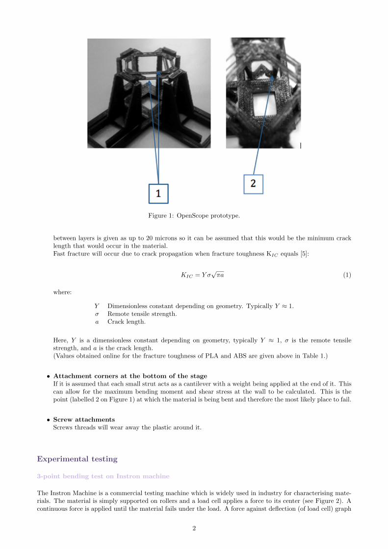
Figure 1: OpenScope prototype.
between layers is given as up to 20 microns so it can be assumed that this would be the minimum cracklength that would occur in the material.Fast fracture will occur due to crack propagation when fracture toughness KIC equals [5]:
KIC = Y σ√πa (1)
where:
Y Dimensionless constant depending on geometry. Typically Y ≈ 1.σ Remote tensile strength.a Crack length.
Here, Y is a dimensionless constant depending on geometry, typically Y ≈ 1, σ is the remote tensilestrength, and a is the crack length.(Values obtained online for the fracture toughness of PLA and ABS are given above in Table 1.)
• Attachment corners at the bottom of the stageIf it is assumed that each small strut acts as a cantilever with a weight being applied at the end of it. Thiscan allow for the maximum bending moment and shear stress at the wall to be calculated. This is thepoint (labelled 2 on Figure 1) at which the material is being bent and therefore the most likely place to fail.
• Screw attachmentsScrews threads will wear away the plastic around it.
Experimental testing
3-point bending test on Instron machine
The Instron Machine is a commercial testing machine which is widely used in industry for characterising mate-rials. The material is simply supported on rollers and a load cell applies a force to its center (see Figure 2). Acontinuous force is applied until the material fails under the load. A force against deflection (of load cell) graph
2

(a) Test 1 (b) Test 3
Figure 2: Instron machine carrying out 3 point bending tests
is plotted which allows the Young’s modulus (E) of the material to be calculated using Equation 2.
E =kL3
4bd3(2)
where:
k Gradient of the linear part of the force-deflection graph.L Distance between supports.b Width of sample.d Thickness of sample.
aaaaaaaaa
BeamThickness (mm)
3D PrinterHead II Makerbot Ultimaker 2
0.8 7 31 3 33 3 3
Table 3: Beams tested . The print settings are as follows, Infill:20%, Layer Resolution:0.2mm, Print speed:50mms, Travel speed: 150mms, Print-bed temperature: 72◦C. The Makerbot beams were of length 100mmwhile the Ultimaker 2 beams were of length 150mm.
Samplenumber
Details Length(mm)
Base(mm)
Thickness(mm)
Young’s Modulus(GPa)
1 Makerbot , PLA 100 200 3 2.472 Makerbot, PLA 100 20 1 1.553 Ultimaker 2, PLA
(printed base side down)150 20 3 32.1
4 Ultimaker 2, PLA(printed base side up)
150 20 3 27.2
5 Ultimaker 2, PLA 150 20 1 31.16 Ultimaker 2, PLA 150 20 0.8 52.0
Table 4: Samples used in three point bending test with corresponding calculated Young’s Modulus value.
3
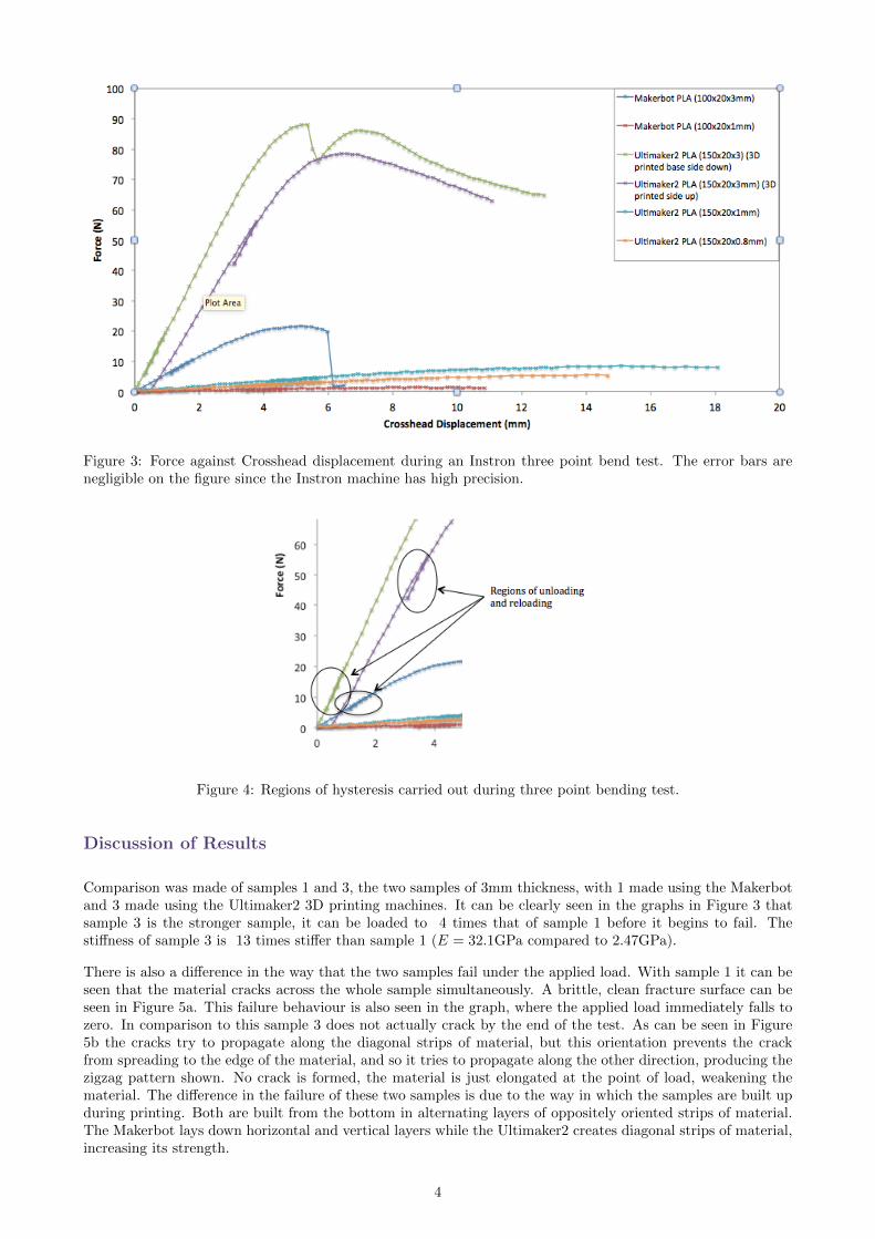
Figure 3: Force against Crosshead displacement during an Instron three point bend test. The error bars arenegligible on the figure since the Instron machine has high precision.
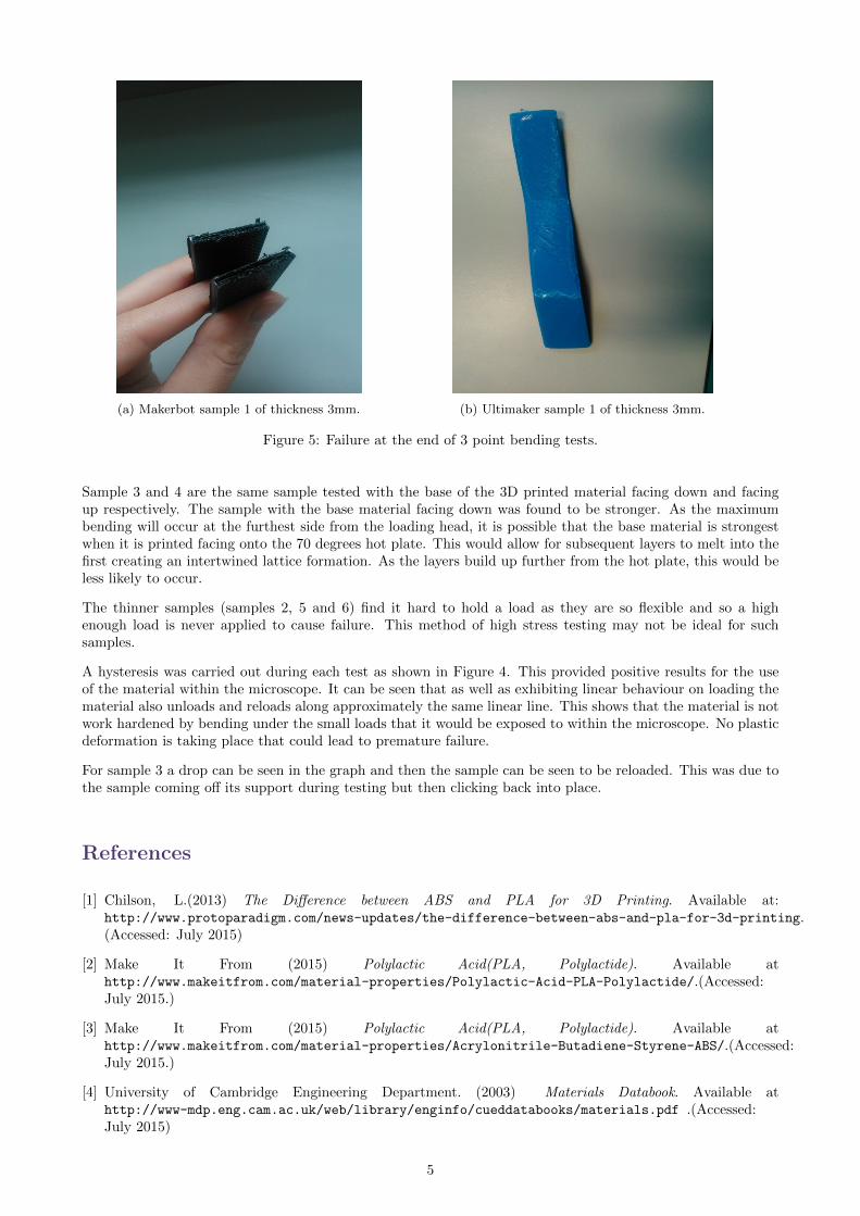
Figure 4: Regions of hysteresis carried out during three point bending test.
Discussion of Results
Comparison was made of samples 1 and 3, the two samples of 3mm thickness, with 1 made using the Makerbotand 3 made using the Ultimaker2 3D printing machines. It can be clearly seen in the graphs in Figure 3 thatsample 3 is the stronger sample, it can be loaded to 4 times that of sample 1 before it begins to fail. Thestiffness of sample 3 is 13 times stiffer than sample 1 (E = 32.1GPa compared to 2.47GPa).
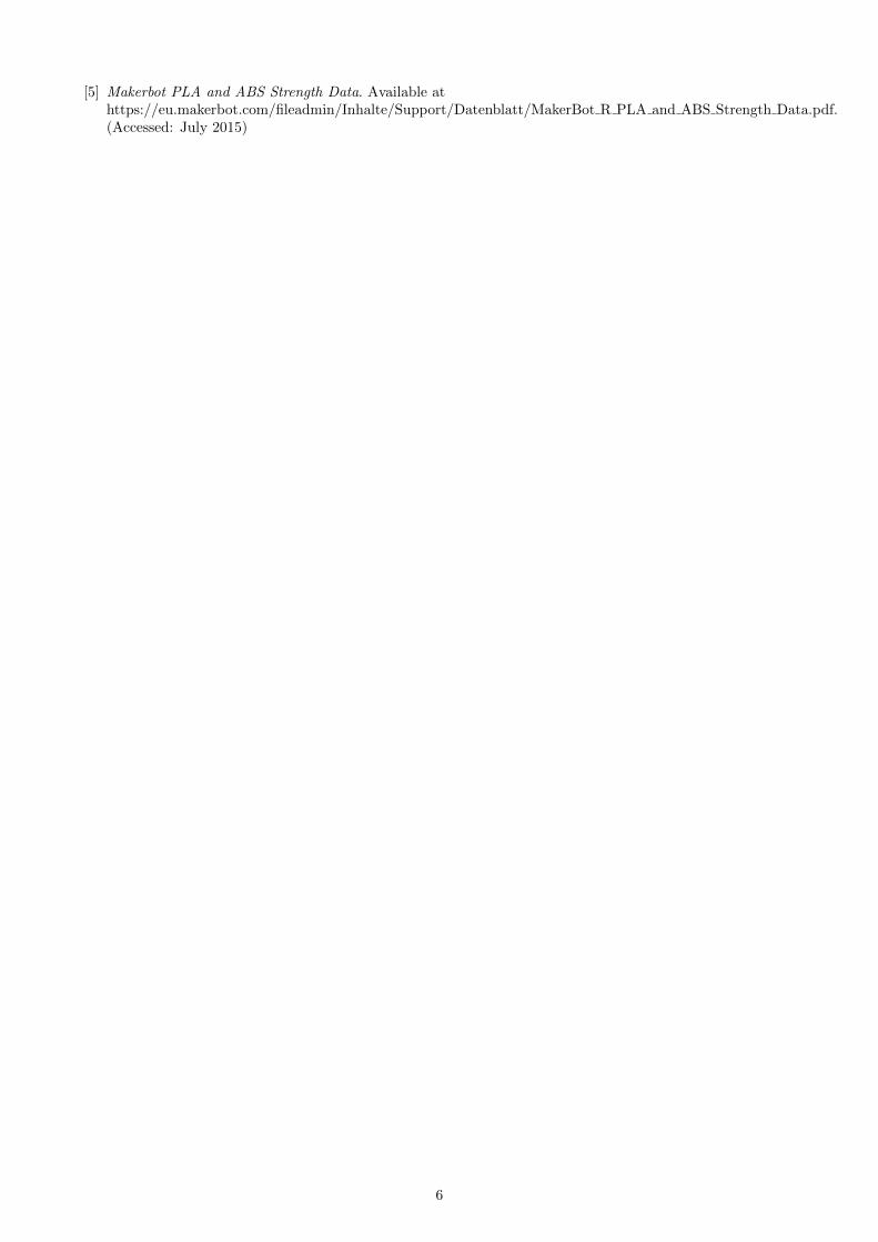
There is also a difference in the way that the two samples fail under the applied load. With sample 1 it can beseen that the material cracks across the whole sample simultaneously. A brittle, clean fracture surface can beseen in Figure 5a. This failure behaviour is also seen in the graph, where the applied load immediately falls tozero. In comparison to this sample 3 does not actually crack by the end of the test. As can be seen in Figure5b the cracks try to propagate along the diagonal strips of material, but this orientation prevents the crackfrom spreading to the edge of the material, and so it tries to propagate along the other direction, producing thezigzag pattern shown. No crack is formed, the material is just elongated at the point of load, weakening thematerial. The difference in the failure of these two samples is due to the way in which the samples are built upduring printing. Both are built from the bottom in alternating layers of oppositely oriented strips of material.The Makerbot lays down horizontal and vertical layers while the Ultimaker2 creates diagonal strips of material,increasing its strength.
4
(a) Makerbot sample 1 of thickness 3mm. (b) Ultimaker sample 1 of thickness 3mm.
Figure 5: Failure at the end of 3 point bending tests.
Sample 3 and 4 are the same sample tested with the base of the 3D printed material facing down and facingup respectively. The sample with the base material facing down was found to be stronger. As the maximumbending will occur at the furthest side from the loading head, it is possible that the base material is strongestwhen it is printed facing onto the 70 degrees hot plate. This would allow for subsequent layers to melt into thefirst creating an intertwined lattice formation. As the layers build up further from the hot plate, this would beless likely to occur.
The thinner samples (samples 2, 5 and 6) find it hard to hold a load as they are so flexible and so a highenough load is never applied to cause failure. This method of high stress testing may not be ideal for suchsamples.
A hysteresis was carried out during each test as shown in Figure 4. This provided positive results for the useof the material within the microscope. It can be seen that as well as exhibiting linear behaviour on loading thematerial also unloads and reloads along approximately the same linear line. This shows that the material is notwork hardened by bending under the small loads that it would be exposed to within the microscope. No plasticdeformation is taking place that could lead to premature failure.
For sample 3 a drop can be seen in the graph and then the sample can be seen to be reloaded. This was due tothe sample coming off its support during testing but then clicking back into place.
References
[1] Chilson, L.(2013) The Difference between ABS and PLA for 3D Printing. Available at:http://www.protoparadigm.com/news-updates/the-difference-between-abs-and-pla-for-3d-printing.(Accessed: July 2015)
[2] Make It From (2015) Polylactic Acid(PLA, Polylactide). Available athttp://www.makeitfrom.com/material-properties/Polylactic-Acid-PLA-Polylactide/.(Accessed:July 2015.)
[3] Make It From (2015) Polylactic Acid(PLA, Polylactide). Available athttp://www.makeitfrom.com/material-properties/Acrylonitrile-Butadiene-Styrene-ABS/.(Accessed:July 2015.)
[4] University of Cambridge Engineering Department. (2003) Materials Databook. Available athttp://www-mdp.eng.cam.ac.uk/web/library/enginfo/cueddatabooks/materials.pdf .(Accessed:July 2015)
5
[5] Makerbot PLA and ABS Strength Data. Available athttps://eu.makerbot.com/fileadmin/Inhalte/Support/Datenblatt/MakerBot R PLA and ABS Strength Data.pdf.(Accessed: July 2015)
6