matrix decomposition architecture for mimo systems: …studer/papers/07asilomar-svd.pdf · matrix...
TRANSCRIPT

Matrix Decomposition Architecture for MIMOSystems: Design and Implementation Trade-offs
C. Studer∗, P. Blösch, P. Friedli, and A. Burg∗
∗Integrated Systems Laboratory, ETH Zurich, Switzerlandemail: {studer, apburg}@iis.ee.ethz.ch
Abstract— The singular value decomposition (SVD) and theQR decomposition (QRD) are two prominent matrix decomposi-tion algorithms used in various signal processing applications.In the field of multiple-input multiple-output (MIMO) com-munication systems, the SVD and the QRD are employed forbeamforming and for channel-matrix preprocessing for MIMOdetection, respectively. In this paper, we describe a minimum-area matrix decomposition architecture that is programmableto perform QRD and SVD with variable precision and weinvestigate the associated design and implementation trade-offs.Our reference implementation achieves a hardware efficiency ofup to 325 k SVDs/s/mm2 and 1.92 M QRDs/s/mm2 for complex-valued 4× 4-matrices in 0.18 µm CMOS technology.
I. INTRODUCTION
Multiple-input multiple-output (MIMO) communicationsystems [1] constitute the basis for many upcoming wirelesscommunication standards (e.g., IEEE 802.11n) and offer in-creased spectral efficiency (compared to single-antenna sys-tems) by transmitting multiple data streams concurrently in thesame frequency band. Matrix decomposition algorithms [2],such as the singular value decomposition (SVD) or the QRdecomposition (QRD), have applications in various signalprocessing fields. The SVD, for example, is used in arrayprocessing or data compression, but can also be applied toMIMO systems in order to increase the system performanceby the use of beamforming and power allocation. The QRD,for example, is a key prerequisite for many advanced MIMOdetectors, such as the sphere decoder [3].
The SVD and the QRD mainly base on a specific sequenceof Givens rotations [2]. CORDIC (coordinate rotation digitalcomputer) algorithms have shown to be a suitable tool toefficiently perform Givens rotations in hardware [4]. Sincethe QRD only requires a subset of operations required for theSVD, an architecture which allows to compute the SVD wouldalso provide all the functionality to compute the QRD. Hence,a programmable matrix decomposition architecture based onCORDIC arithmetic results in a single matrix decompositionunit (MDU) and is suitable for both decomposition algorithms.
Due to the relatively high computational complexity of theSVD, systolic arrays based on the Jacobi method have beenproposed [4]–[6]. As illustrated in Fig. 1, systolic arrays lie onone end of the area/delay trade-off and are usually designed toachieve short computation time at the cost of large circuit area.However, in MIMO-OFDM systems [1] for example, multiple
This work was supported by the STREP project No. IST-026905(MASCOT) within the Sixth Framework Programme (FP6) of the EuropeanCommission.
problems need to be solved concurrently, where the numberof parallel tasks corresponds to the number of OFDM tones.The throughput of fast but large architectures (e.g., systolicarrays) is often difficult to match to an arbitrary number ofproblems, e.g., one systolic array might be insufficient in termsof throughput but two might exceed the available circuit area.Low-area architectures can be obtained by the use of time-sharing and lie on the other end of the area/delay trade-off (seeFig. 1). Ideally, time-shared architectures are equally efficient(in terms of area times the computation time) as systolic arraysand have the key advantage to be easily adaptable to individualthroughput requirements by the use of parallel instantiation,i.e., the target throughput can be achieved by replication of alow-area instance. Additional area savings, while not reducingthe decomposition throughput, can be obtained by iterativedecomposition of each instance (see Fig. 1).
Contributions: We present reference VLSI implementationresults of two MDUs optimzied for MIMO systems. The low-area implementation mainly bases on CORDIC arithmetic andis able to perform the QRD and the SVD of complex-valued4× 4 matrices. In order to improve the overall efficiency, theinvolved design and implementation trade-offs are investigatedin detail. We present two architecture variants: one unit hasbeen optimized for throughput and the other offers enhancedflexibility by controlling a precision/throughput trade-off.
Outline: The remainder of this paper is organized as fol-lows. In Sec. II the SVD and QRD algorithms are describedand all required operations are identified. The time-shared ma-trix decomposition archtecture is described in Sec. III and theassociated design and implementation trade-offs are exploredin Sec. IV. In Sec. V, we provide VLSI implementation resultsand conclude in Sec. VI.
log(Time)
log(Area)
time sharing
replication
1
2 systolic array
ideal effect
1
2 time-sharedarchitecture
constanthardware-efficiency
iterativedecomposition
Fig. 1. Ideal impact of architectural transformations [7] on systolic arraysand time-shared architectures. The dashed box corresponds to the investigateddesign-space exploration for both MDUs by the use of iterative decomposition.

A =
C C C
C C C
C C C
C C
C C
C C
R
0
0
C C
C C
R
0
0
R 0
C
C
R
0
0
R 0
R
0
0
0
0
R
0
R
R
R
0
R 0
R
0
R
R
R
R
0
R
R
0
R
R
0
R R
0
R
R R
R
0
0
R
R
0
R
R R
R
0
0
0
Bk =
= Bk+1
= B0
LHS
Bidiagonalization:
Diagonalization:
R
0
R
R R0
0
0
0
0
0
0
d1
d2
d3
f1
f2=
R
0
R
R R
R
0
0
0C
RHS LHS
RHS LHS
RHS∗ LHS
RHS LHS
x y
Fig. 2. Illustration of the bidiagonalization and diagonalization phases of theSVD according to [2] for a complex-valued 3×3 matrix. The entries affectedin the corresponding update have been highlighted.
II. MATRIX DECOMPOSITION ALGORITHMS
To identify all required arithmetic operations and the under-lying computational sequences, the SVD and QRD algorithmsare briefly summarized below. More details for both matrixdecomposition algorithms can be found in [2].
A. Singular Value DecompositionThe SVD of a complex-valued M ×N -dimensional matrix
A is defined1 as [8]
A = UΣVH (1)
where U and V are complex-valued unitary matrices ofdimension M ×M and N ×N , respectively. The M ×N -matrix Σ contains the real-valued singular values on itsmain diagonal, i.e., diag(Σ) = {σ1, σ2, . . . , σr}, where r =min{N,M} and σ1 ≥ σ2 ≥ . . . ≥ σr. The SVD procedureunder consideration bases on the Golub-Kahan algorithmdescribed in [2] and mainly performs the SVD in two phases:
1) Bidiagonalization: First, a memory is initialized withM = {IM ,A, IN} where IL stands for a L × L identitymatrix. During the bidiagonalization phase, Givens rotationsare successively applied to A from the left-hand side (LHS)and from the right-hand side (RHS), such that the M × N -dimensional inner matrix A gets bidiagonal and real-valued(denoted by B0) as illustrated in Fig. 2. All Givens rotationsapplied to A from the LHS and RHS are applied to thecorresponding identity matrices. The resulting unitary matricesare denoted by U and VH and the memory content after thebidiagonalization phase corresponds to M =
{U,B0, VH
}where A = UB0VH .
2) Diagonalization: The diagonalization phase consists ofmultiple diagonalization steps (indicated with k) and is illus-trated in Fig. 2. Givens rotations are subsequently applied fromthe LHS and from the RHS to the bidiagonal matrix Bk such
1In the following, the superscripts H and T stand for conjugate transposi-tion and transposition, respectively.
Matrix Memory
Sequencer
Instr. RAM64x20 bit
48x32 bit SRAM
CORDIC MAC
Arithmetic Unit
FSM
input/output interface
Fig. 3. Matrix decomposition architecture overview: the instruction-basedsequencer controls the arithmetic unit and the matrix memory, in order toperform the decomposition sequence stored in the instruction RAM.
that all off-diagonal entries fi (for i = 1, 2, . . . , r − 1) of Bk
become zero. The diagonalization phase is stopped wheneverall fi are considered to be zero and all di (for i = 1, 2, . . . , r)correspond to the unordered singular values. In order to ensureconvergence of the diagonalization phase and to reduce theoverall computation time of the SVD, the first Givens rotationof each diagonalization step (indicated with RHS∗ in Fig. 2) isperformed with a modified input vector [x y]T , where y = t12and x = t11 − µ uses the Wilkinson shift [2]
µ = an + c− sign(c)√
a2 + b2n−1 (2)
with c = 12 (an−1−an), T = BH
k Bk, and the trailing non-zerosub-matrix of T corresponds to
T(n− 1 : n, n− 1 : n) =(
an−1 bn−1
b∗n−1 an
). (3)
Analogous to the bidiagonalization phase, all Givens rotationsare also applied to the corresponding unitary matrices suchthat finally, M =
{U,Σ,VH
}is the SVD in (1).
B. QR Decomposition
The QR decomposition of a M ×N -dimensional complex-valued matrix A is defined as [8]
A = QR (4)
where Q is a complex-valued M×N -matrix with orthonormalcolums and the upper-triangular N × N -matrix R has real-valued entries on its main diagonal. The QRD is performedin a similar fashion as the bidiagonalization phase of theSVD (cf. Fig. 2) where only the LHS Givens rotations areapplied. This minor modification of the SVD algorthm resultsin an upper-triangular matrix R with real-valued entries on itsmain diagonal. All Givens rotations applied from the LHSto A are also applied to the unitary matrix Q such thatM = {Q,R, IN} corresponds to the QRD in (4).
III. VLSI ARCHITECTURE
In contrast to a systolic array implementation, we describe alow-area matrix decomposition architecture, which is designedto operate on complex-valued 4×4-dimensional matrices. Thetime-shared architecture is depicted in Fig. 3 and consists oftree main components described in the following.

register
multiplexer
arith. shift right
add/subtract unit
unroll factor: 1unroll factor: 3
+/-+/-+/-
+/- +/-
+/- +/- +/- +/-
ASR
ASR ASR
ASR ASR
ASR ASR
ASR ASR
MUX
MUXMUXMUX MUX
Fig. 4. CORDIC architecture overview: iterative decomposition can (ideally)reduce the area without affecting the computation time per CORDIC. Theunroll factor corresponds to the number of micro-rotations per clock cycle.
A. Matrix Memory
The matrix memory provides storage for three complex-valued 4× 4 matrices M =
{M1,M2,M3
}, which is suffi-
cient to store the result of an SVD and of a QRD (see Sec. II).A complex value in M is stored at a single memory adress, is32 bits wide, and each real and imaginary part requires 16 bits.The matrix memory consists of a two-port 48× 32 bit SRAMand requires 0.06 mm2 in 0.18 µm CMOS technology. Thematrix memory interface allows to read or write two differentreal or imaginary parts in at most two clock cycles.
B. Arithmetic Unit
In order to design a high-level VLSI architecture of thearithmetic unit (AU), Givens rotations, square-roots, multi-plications, and additions/subtractions are required to computethe SVD and the QRD (cf. Sec. II). Givens rotations and thesquare root can efficiently be computed by CORDIC, whereasmultiplications and additions/subtractions are computed in amultiply-accumulate (MAC) unit.
CORDIC Unit: CORDICs can efficiently compute two-dimensional rotations [9] by performing a series of micro-rotations with the aid of shifts and additions/subtractions(cf. Fig. 4). To keep the circuit area low, a single CORDICis used by the means of time sharing and has been designedto support vectoring and rotation. A complex-valued Givensrotation is performed by three real-valued vectoring CORDICs(denoted by C1, C2, and C3), i.e.,[
CC
]C1→
[RC
]C2→
[RR
]C3→
[R0
].
In order to perform the corresponding rotation on a complex-valued 2-dimensional vector, four rotation CORDICs are re-quired: the first two (C1 and C2) rotate each complex entryindependently, whereas the third and fourth CORDICs rotatesthe real and imaginary part of both complex values by C3.
We emphasize that the square-root required in (2) canefficiently be computed with the CORDIC in vectoring mode,
since√
d2 + b2n−1 corresponds to the nonzero result of the
CORDIC with [d bn−1]T applied to the input.Multiply-Accumulate Unit: To compute the trailing sub-
matrix of T = BHk Bk as described in (3), a real-valued
multiply-accumulate (MAC) unit has been instantiated. Themultiplier can be switched off in order to perform additionsor subtractions required in (2).
C. Instruction-Based SequencerThe programmable MDU contains a micro-code controlled
sequencer. This sequencer consists of a 64× 20 bit instructionRAM (of size 0.04 mm2 in 0.18 µm CMOS technology) thatprovides storage for 64 instructions. The finite state machine(FSM) decodes instructions, generatates memory adresses, andprovides control signals for the AU.
Instruction Set: The SVD and QRD mainly base on aspecific rotation sequence applied to the matrices in M(cf. Sec. III-A). To this end, a set of eight instructions hasbeen defined. Four instructions are used to apply CORDICsfrom the left-hand side (LHS) or the right-hand side (RHS) toone complex-value or two real/imaginary-valued entries of M2
and to update all other affected entries in M. One instructionis used to initialize the diagonalization phase of the SVDwhich subsequently performs all required diagonalization stepsin a self-controlled manner. The remaining instructions arereserved to configure the number of CORDIC micro-rotations(see Sec. IV-A) or to control the program flow. The SVD of acomplex-valued 4×4 matrix requires 27 instructions, whereasa QRD of equal size requires only 17 instructions.
SVD-Algorithm Modifications: To simplify the diagonaliza-tion phase of the SVD and to obtain a fixed throughput, thefollowing modifications have been applied to [2]:
1) Off-diagonal entries of Bk (see Fig. 2) are consideredto be zero, whenever fi < 2−ε for i = 1, 2, . . . , r − 1.
2) Since the computational complexity of the diagonaliza-tion phase is data dependent, an early-stopping criterionhas been introduced to obtain a fixed decompositionthroughput. Whenever k = Kmax, the diagonalizationphase is stopped and the current M is used as anestimate of (1).
Note that ε and Kmax can be defined in the SVD-initializationinstruction, which allows to reconfigure the arithmetic preci-sion and the decomposition throughput at run time.
IV. IMPLEMENTATION TRADE-OFFS
To reduce the area of the MDU and to improve the overallefficiency, implementation trade-offs associated with arith-metic precision, circuit area, and throughput are investigatedin the following.
A. Fixed-Point Implementation Trade-offsThe arithmetic precision of a fixed-point implementation is
assessed by the bit error rate (BER) of an IEEE 802.11n-based MIMO-OFDM system with coded beamforming [10].The baseband input-output relation of the wireless channelis y = Hs + n where H corresponds to the MR × MT -dimensional channel matrix, s denotes the MT -dimensional

5 10 15 20 2510-6
10-5
10-4
10-3
10-2
10-1
100
SNR [dB]
BER
CORDIC m=12CORDIC m=10CORDIC m=8CORDIC m=6Floating-point
Fig. 5. Fixed-point SVD performance (16 fractional bits in the CORDIC,ε = 7, and Kmax = 7), measured in a beamformed MIMO-OFDM system.The number of micro-rotations in the CORDIC (denoted by m) has asignificant impact on the BER.
transmit signal, n the MR-dimensional Gaussian noise vector,and y the MR-dimensional receive signal. Beamforming issimulated by computing the fixed-point SVD of the channelmatrix H and by transmitting s = Vs. The receiver convertsthe input-output relation into MT single-input single-outputchannels
yi = σisi + ni for i = 1, 2, . . . ,MT
where y = UHy, σi is the ith singular value, and thenoise vector n has equal statistics as n. Finally, a soft-outputdemapper produces reliability information for the subsequentsoft-input channel decoder.
Fixed-Point Implementation: To convert the floating-pointmodel in a fixed-point implementation, the floating-point SVDhas been simulated to determine the threshold parameter εand the required maximum number of diagonalization steps.Simulations have shown that setting ε = 7 and Kmax = 7 doesnot result in a significant BER performance loss. Note thatreducing ε or increasing Kmax only increases the computa-tional complexity of the SVD and does not improve the errorrate performance. Further simulations have shown that a near-optimal BER is achieved by using 16 fractional bits withinthe CORDIC. Finally, the required number of micro-rotationsin the CORDIC has been evaluated. Figure Fig. 5 showsthe impact of micro-rotations to the BER of a beamformedMIMO-OFDM simuation2. At least 12 micro-rotations arerequired to acheive a BER less than 10−6. Reducing thenumber of micro-rotations results in a BER floor, which isnot suitable for the scenario under consideration.
Precision/Throughput Trade-off: The number of micro ro-tations in the CORDIC directly influences the arithmeticprecision of the MDU (see Fig. 5) and has also a significantimpact on the throughput. A lower number of micro-rotations
2We consider a convolutionally encoded (rate 1/2, generator polynomials[133o 171o], constraint length 7, random interleaving) MIMO-OFDM systemwith beamforming [10], four transmit and receive antennas, 16-QAM (usingGray mapping), 64 tones, and soft-input Viterbi decoding. One codeblockcorresponds to 1024 bits, a TGn type C [11] channel model is used, andperfect channel state information at the transmitter and receiver is assumed.
0 5 10 15 20 25 300
0.05
0.1
0.15
0.2
0.25
Maximum SVD computation time [µs]
Area
of a
rithm
etic
unit
[mm
2 ]
12 CORDIC micro-rotations10 CORDIC micro-rotations8 CORDIC micro-rotations6 CORDIC micro-rotations
6
43
2
1111
222
345
AU II
AU I
Fig. 6. Area/delay trade-off achievable by iterative decomposition of theCORDIC: the fast AU I computes the SVD with high precision (i.e., 12micro-rotations). The precision of AU II can be adjusted at run time to 12,10, 8, and 6 micro-rotations. The numbers next to the curves correspond tothe CORDIC unroll factor.
requires less clock cycles, which results in lowered computa-tional complexity. We emphasize that the arithmetic precisionrequirements of a QRD for MIMO detection are usually lowerthan the precision for the SVD in the scenario consideredabove. As noted in [12], nine micro-rotations have found tobe sufficient for a QRD and thus, it is beneficial to lower theprecision in order to increase the decomposition speed. To thisend, we propose a tunable arithmetic unit (denoted by AU II),where the number of micro-rotations is programmable, whichallows to adjust the precision/throughput trade-off at run time.The maximum number of micro-rotations has been set to 12to support sufficient precision for computing the SVD. Anunroll factor of two has been chosen which allows to chose thenumber of micro-rotations from 12, 10, 8, and 6, dependingon the application and precision requirements. Note that allBERs achievable by AU II are shown in Fig. 5.
B. Area/Delay Trade-offReplication of a low-area unit can be used to achieve a given
throughput. Lower area implies that the target throughput canbe obtained more accurately. Hence, additional reduction interms of area per decomposition unit, without a significantthroughput decrease is highly desirable. To this end, iterativedecomposition has been applied to the CORDIC unit todetermine the optimum choice of the unroll factor. Sinceonly the area of the AU is affected, the area/delay trade-offassociated with the maximum number of micro-rotations andthe CORDIC unroll factor is shown in Fig. 6. Two differentMDUs have been designed: MDU I uses of the faster butless-flexible AU I (using 12 micro rotations and an unrollfactor of six), whereas MDU II employs the slightly slowerbut configurable AU II (using an unroll factor of two with12, 10, 8, and 6 micro rotations), which allows to control theprecision/throughput trade-off at run time. Note that the criticalpath is not only determined by the CORDIC, but also by theMAC unit. Thus, to align the critical paths of both units, onepipelining register has been inserted in the multiplier if theCORDIC unroll factor is less than four.
M MC C
MDU IMDU II
unrelated design
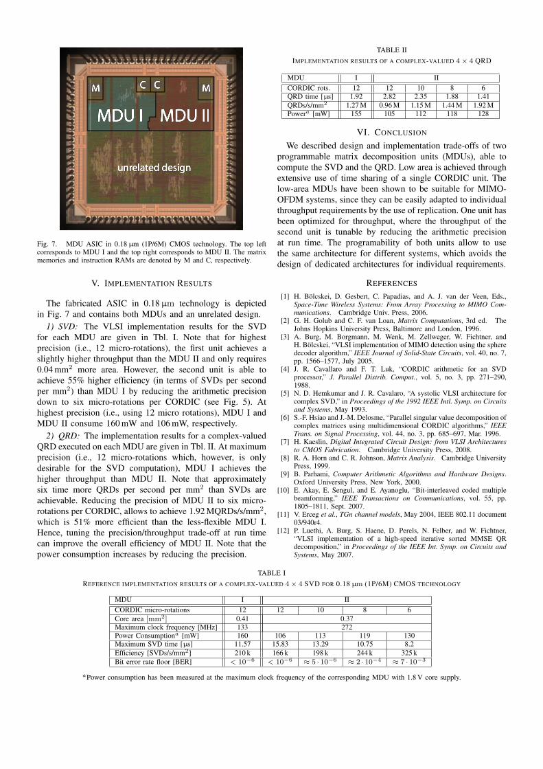
Fig. 7. MDU ASIC in 0.18 µm (1P/6M) CMOS technology. The top leftcorresponds to MDU I and the top right corresponds to MDU II. The matrixmemories and instruction RAMs are denoted by M and C, respectively.
V. IMPLEMENTATION RESULTS
The fabricated ASIC in 0.18 µm technology is depictedin Fig. 7 and contains both MDUs and an unrelated design.
1) SVD: The VLSI implementation results for the SVDfor each MDU are given in Tbl. I. Note that for highestprecision (i.e., 12 micro-rotations), the first unit achieves aslightly higher throughput than the MDU II and only requires0.04 mm2 more area. However, the second unit is able toachieve 55% higher efficiency (in terms of SVDs per secondper mm2) than MDU I by reducing the arithmetic precisiondown to six micro-rotations per CORDIC (see Fig. 5). Athighest precision (i.e., using 12 micro rotations), MDU I andMDU II consume 160 mW and 106 mW, respectively.
2) QRD: The implementation results for a complex-valuedQRD executed on each MDU are given in Tbl. II. At maximumprecision (i.e., 12 micro-rotations which, however, is onlydesirable for the SVD computation), MDU I achieves thehigher throughput than MDU II. Note that approximatelysix time more QRDs per second per mm2 than SVDs areachievable. Reducing the precision of MDU II to six micro-rotations per CORDIC, allows to achieve 1.92 MQRDs/s/mm2,which is 51% more efficient than the less-flexible MDU I.Hence, tuning the precision/throughput trade-off at run timecan improve the overall efficiency of MDU II. Note that thepower consumption increases by reducing the precision.
TABLE IIIMPLEMENTATION RESULTS OF A COMPLEX-VALUED 4× 4 QRD
MDU I IICORDIC rots. 12 12 10 8 6QRD time [µs] 1.92 2.82 2.35 1.88 1.41QRDs/s/mm2 1.27 M 0.96 M 1.15 M 1.44 M 1.92 MPowera [mW] 155 105 112 118 128
VI. CONCLUSION
We described design and implementation trade-offs of twoprogrammable matrix decomposition units (MDUs), able tocompute the SVD and the QRD. Low area is achieved throughextensive use of time sharing of a single CORDIC unit. Thelow-area MDUs have been shown to be suitable for MIMO-OFDM systems, since they can be easily adapted to individualthroughput requirements by the use of replication. One unit hasbeen optimized for throughput, where the throughput of thesecond unit is tunable by reducing the arithmetic precisionat run time. The programability of both units allow to usethe same architecture for different systems, which avoids thedesign of dedicated architectures for individual requirements.
REFERENCES
[1] H. Bölcskei, D. Gesbert, C. Papadias, and A. J. van der Veen, Eds.,Space-Time Wireless Systems: From Array Processing to MIMO Com-munications. Cambridge Univ. Press, 2006.
[2] G. H. Golub and C. F. van Loan, Matrix Computations, 3rd ed. TheJohns Hopkins University Press, Baltimore and London, 1996.
[3] A. Burg, M. Borgmann, M. Wenk, M. Zellweger, W. Fichtner, andH. Bölcskei, “VLSI implementation of MIMO detection using the spheredecoder algorithm,” IEEE Journal of Solid-State Circuits, vol. 40, no. 7,pp. 1566–1577, July 2005.
[4] J. R. Cavallaro and F. T. Luk, “CORDIC arithmetic for an SVDprocessor,” J. Parallel Distrib. Comput., vol. 5, no. 3, pp. 271–290,1988.
[5] N. D. Hemkumar and J. R. Cavalaro, “A systolic VLSI architecture forcomplex SVD,” in Proceedings of the 1992 IEEE Intl. Symp. on Circuitsand Systems, May 1993.
[6] S.-F. Hsiao and J.-M. Delosme, “Parallel singular value decomposition ofcomplex matrices using multidimensional CORDIC algorithms,” IEEETrans. on Signal Processing, vol. 44, no. 3, pp. 685–697, Mar. 1996.
[7] H. Kaeslin, Digital Integrated Circuit Design: from VLSI Architecturesto CMOS Fabrication. Cambridge University Press, 2008.
[8] R. A. Horn and C. R. Johnson, Matrix Analysis. Cambridge UniversityPress, 1999.
[9] B. Parhami, Computer Arithmetic Algorithms and Hardware Designs.Oxford University Press, New York, 2000.
[10] E. Akay, E. Sengul, and E. Ayanoglu, “Bit-interleaved coded multiplebeamforming,” IEEE Transactions on Communications, vol. 55, pp.1805–1811, Sept. 2007.
[11] V. Erceg et al., TGn channel models, May 2004, IEEE 802.11 document03/940r4.
[12] P. Luethi, A. Burg, S. Haene, D. Perels, N. Felber, and W. Fichtner,“VLSI implementation of a high-speed iterative sorted MMSE QRdecomposition,” in Proceedings of the IEEE Int. Symp. on Circuits andSystems, May 2007.
TABLE IREFERENCE IMPLEMENTATION RESULTS OF A COMPLEX-VALUED 4× 4 SVD FOR 0.18 µm (1P/6M) CMOS TECHNOLOGY
MDU I IICORDIC micro-rotations 12 12 10 8 6Core area [mm2] 0.41 0.37Maximum clock frequency [MHz] 133 272Power Consumptiona [mW] 160 106 113 119 130Maximum SVD time [µs] 11.57 15.83 13.29 10.75 8.2Efficiency [SVDs/s/mm2] 210 k 166 k 198 k 244 k 325 kBit error rate floor [BER] < 10−6 < 10−6 ≈ 5 · 10−6 ≈ 2 · 10−4 ≈ 7 · 10−3
aPower consumption has been measured at the maximum clock frequency of the corresponding MDU with 1.8 V core supply.