matsushita - pi4 - home · as with all matsushita products, the plcs undergo extre-mely rigorous...
TRANSCRIPT
MatsushitaProgrammable Logic Controllers
2
The Matsushita PAdvantages o
Powerful Hardware SolutionsPLCs offer an outstanding price-performance ratio
which incorporates numerous functions into a very compactbody. Even in the smallest size they provide a powerful in-struction set which allows the system to handle demandingtasks such as analogue control, networking and positioningcontrol.
Innovative Programming SoftwareOur PLC programming software was one of the first on themarket according to the international standard IEC 61131-3.Numerous libraries that incorporate a lot of our know-howensure the reusability of ready-made functions and functionblocks and save time for programming and debugging.
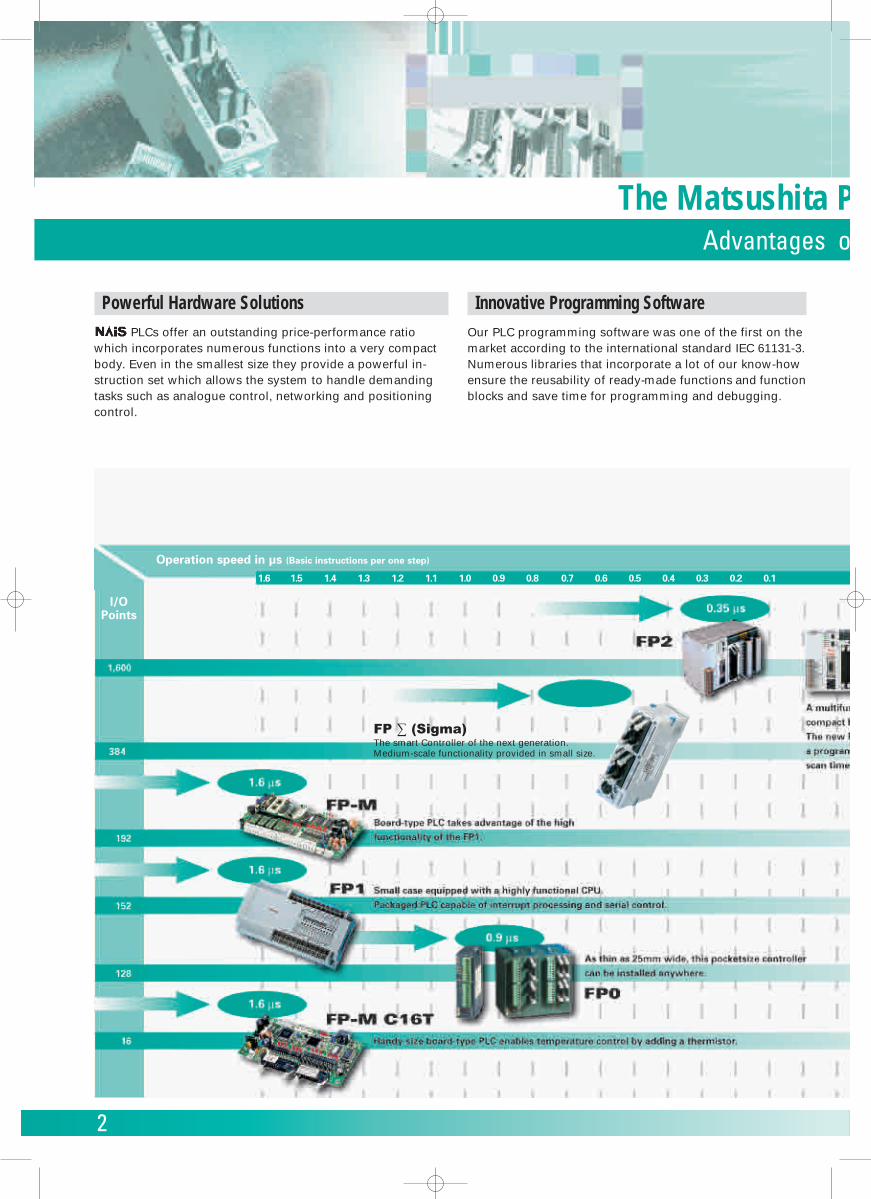
FP ∑ (Sigma)The smart Controller of the next generation.Medium-scale functionality provided in small size.
I/OPoints
Operation speed in µs (Basic instructions per one step)
1.6 1.5 1.4 1.3 1.2 1.1 1.0 0.9 0.8 0.7 0.6 0.5 0.4 0.3 0.2 0.1
a PLC Range es of PLC Control
3
Long-Life QualityAs with all Matsushita products, the PLCs undergo extre-mely rigorous testing during development that far ex-ceeds the demands that will actually be placed on them.This is a guaranty for the long life of the product in theapplication.
Benefit from good serviceIn addition to a comprehensive PLC range, Matsushita alsooffers the high-quality care demanded from a service-orientedcompany certified according to ISO 9001.Highly trained application engineers can provide customdesigned systems. A sales staff regularly participates in hard-ware and software training courses.
Contents:
FP0 Series ..................................................................................... 5-9
FP ∑ (Sigma)............................................................................. 10-11
Microcontroller FP-M ............................................................... 13-15
FP1 Series ................................................................................. 17-19
FP2 Series ................................................................................. 21-27
Networking Technology........................................................... 28-29
FP Web-Server ............................................................................... 30
FP Modem-EU................................................................................ 31
Programming Software FPWIN Pro............................................. 32
Programming Software FPWIN GR ............................................. 33
PCWAY............................................................................................ 34
Control CommX............................................................................. 35
G-Series Operator Terminals................................................... 36-37
Power Supplies.............................................................................. 38
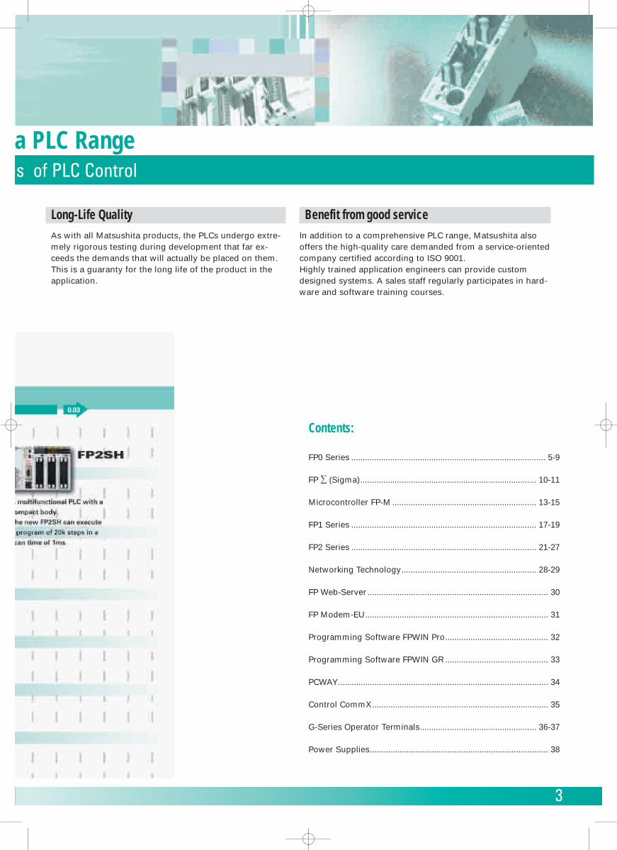
0.03
4
PLC Programming Software conforming to IEC61131-3
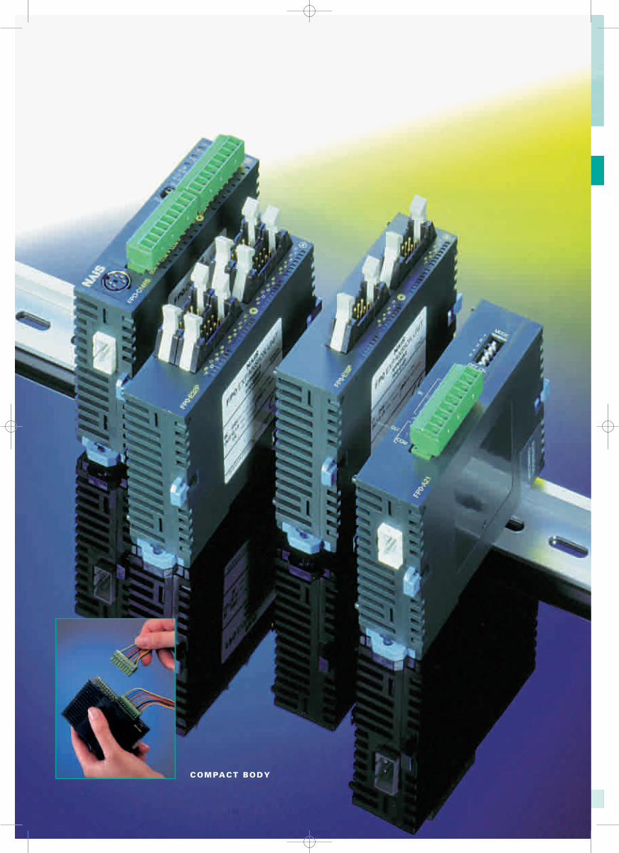
COMPACT BODY
5
FP0 SeriesIncredibly small, as single or even as multiple combined units
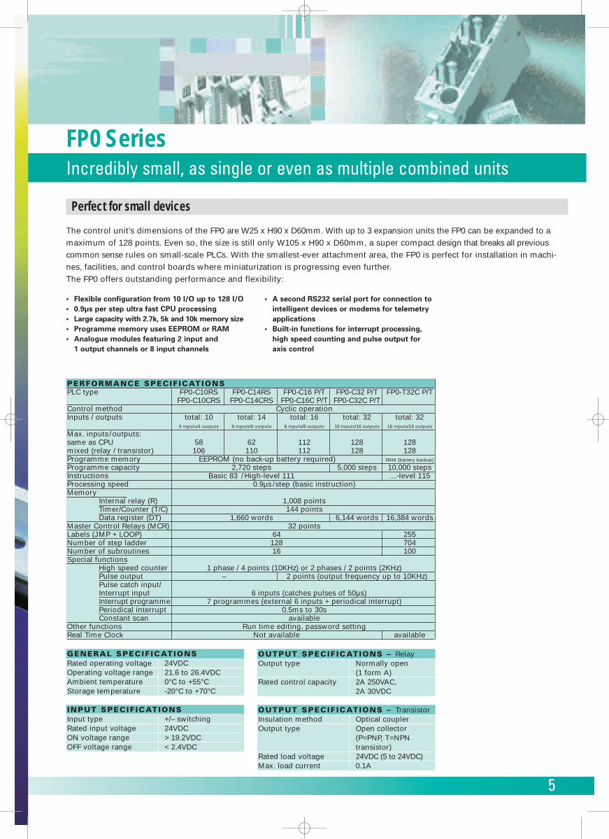
PERFORMANCE SPECIFICATIONSPLC type FP0-C10RS FP0-C14RS FP0-C16 P/T FP0-C32 P/T FP0-T32C P/T
FP0-C10CRS FP0-C14CRS FP0-C16C P/T FP0-C32C P/TControl method Cyclic operationInputs / outputs total: 10 total: 14 total: 16 total: 32 total: 32
6 inputs/4 outputs 8 inputs/6 outputs 8 inputs/8 outputs 16 inputs/16 outputs 16 inputs/16 outputs
Max. inputs/outputs:same as CPU 58 62 112 128 128mixed (relay / transistor) 106 110 112 128 128Programme memory EEPROM (no back-up battery required) RAM (battery backup)
Programme capacity 2,720 steps 5,000 steps 10,000 stepsInstructions Basic 83 / High-level 111 …-level 115Processing speed 0.9µs/step (basic instruction)Memory
Internal relay (R) 1,008 pointsTimer/Counter (T/C) 144 pointsData register (DT) 1,660 words 6,144 words 16,384 words
Master Control Relays (MCR) 32 pointsLabels (JMP + LOOP) 64 255Number of step ladder 128 704Number of subroutines 16 100Special functions
High speed counter 1 phase / 4 points (10KHz) or 2 phases / 2 points (2KHz)Pulse output – 2 points (output frequency up to 10KHz)Pulse catch input/Interrupt input 6 inputs (catches pulses of 50µs)Interrupt programme 7 programmes (external 6 inputs + periodical interrupt)Periodical interrupt 0.5ms to 30sConstant scan available
Other functions Run time editing, password settingReal Time Clock Not available available
OUTPUT SPECIFICATIONS – RelayOutput type Normally open
(1 form A)Rated control capacity 2A 250VAC,
2A 30VDC
OUTPUT SPECIFICATIONS – TransistorInsulation method Optical couplerOutput type Open collector
(P=PNP, T=NPNtransistor)
Rated load voltage 24VDC (5 to 24VDC)Max. load current 0.1A
GENERAL SPECIFICATIONSRated operating voltage 24VDCOperating voltage range 21.6 to 26.4VDCAmbient temperature 0°C to +55°CStorage temperature -20°C to +70°C
INPUT SPECIFICATIONSInput type +/– switchingRated input voltage 24VDCON voltage range > 19.2VDCOFF voltage range < 2.4VDC
Perfect for small devices
The control unit’s dimensions of the FP0 are W25 x H90 x D60mm. With up to 3 expansion units the FP0 can be expanded to amaximum of 128 points. Even so, the size is still only W105 x H90 x D60mm, a super compact design that breaks all previouscommon sense rules on small-scale PLCs. With the smallest-ever attachment area, the FP0 is perfect for installation in machi-nes, facilities, and control boards where miniaturization is progressing even further. The FP0 offers outstanding performance and flexibility:
• Flexible configuration from 10 I/O up to 128 I/O• 0.9µs per step ultra fast CPU processing• Large capacity with 2.7k, 5k and 10k memory size• Programme memory uses EEPROM or RAM• Analogue modules featuring 2 input and
1 output channels or 8 input channels
• A second RS232 serial port for connection to intelligent devices or modems for telemetry applications
• Built-in functions for interrupt processing, high speed counting and pulse output foraxis control
6
FP0 SeriesA wide variety of both single and combined units
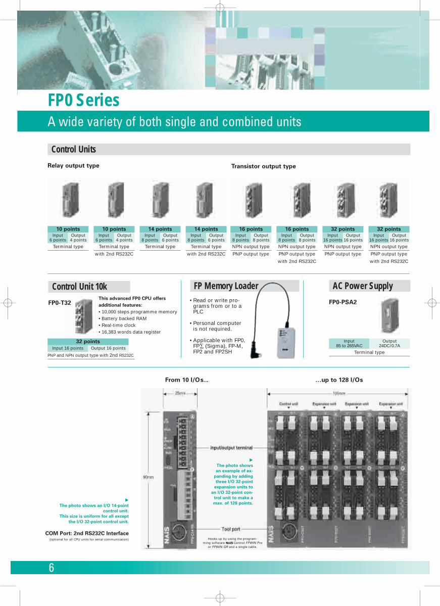
Control Units
Relay output type Transistor output type
AC Power Supply
FP0-PSA2
Control Unit 10k
FP0-T32
Terminal type Terminal type
with 2nd RS232C
Terminal type
with 2nd RS232C
Terminal type
10 pointsInput
6 pointsOutput4 points
10 pointsInput
6 pointsOutput4 points
14 pointsInput
8 pointsOutput6 points
14 pointsInput
8 pointsOutput6 points
NPN output type
PNP output type
NPN output type
PNP output type
NPN output type
PNP output type
with 2nd RS232C
NPN output type
PNP output type
with 2nd RS232C
16 pointsInput
8 pointsOutput8 points
16 pointsInput
8 pointsOutput8 points
32 pointsInput
16 pointsOutput
16 points
32 pointsInput
16 pointsOutput
16 points
From 10 I/Os... …up to 128 I/Os
�The photo shows an I/O 14-point
control unit. This size is uniform for all except
the I/O 32-point control unit.
32 pointsInput 16 points
PNP and NPN output type with 2nd RS232C
Output 16 points
This advanced FP0 CPU offers additional features:• 10,000 steps programme memory• Battery backed RAM• Real-time clock• 16,383 words data register
• Read or write pro-grams from or to aPLC
• Personal computeris not required.
• Applicable with FP0,FP∑ (Sigma), FP-M,FP2 and FP2SH
�The photo showsan example of ex-
panding by addingthree I/O 32-point
expansion units toan I/O 32-point con-
trol unit to make amax. of 128 points.
Hooks up by using the program-ming software Control FPWIN Pro
or FPWIN GR and a single cable.
COM Port: 2nd RS232C Interface(optional for all CPU units for serial communication)
Input85 to 265VAC
Terminal type
Output24DC/0.7A
FP Memory Loader
7
Transistor output type
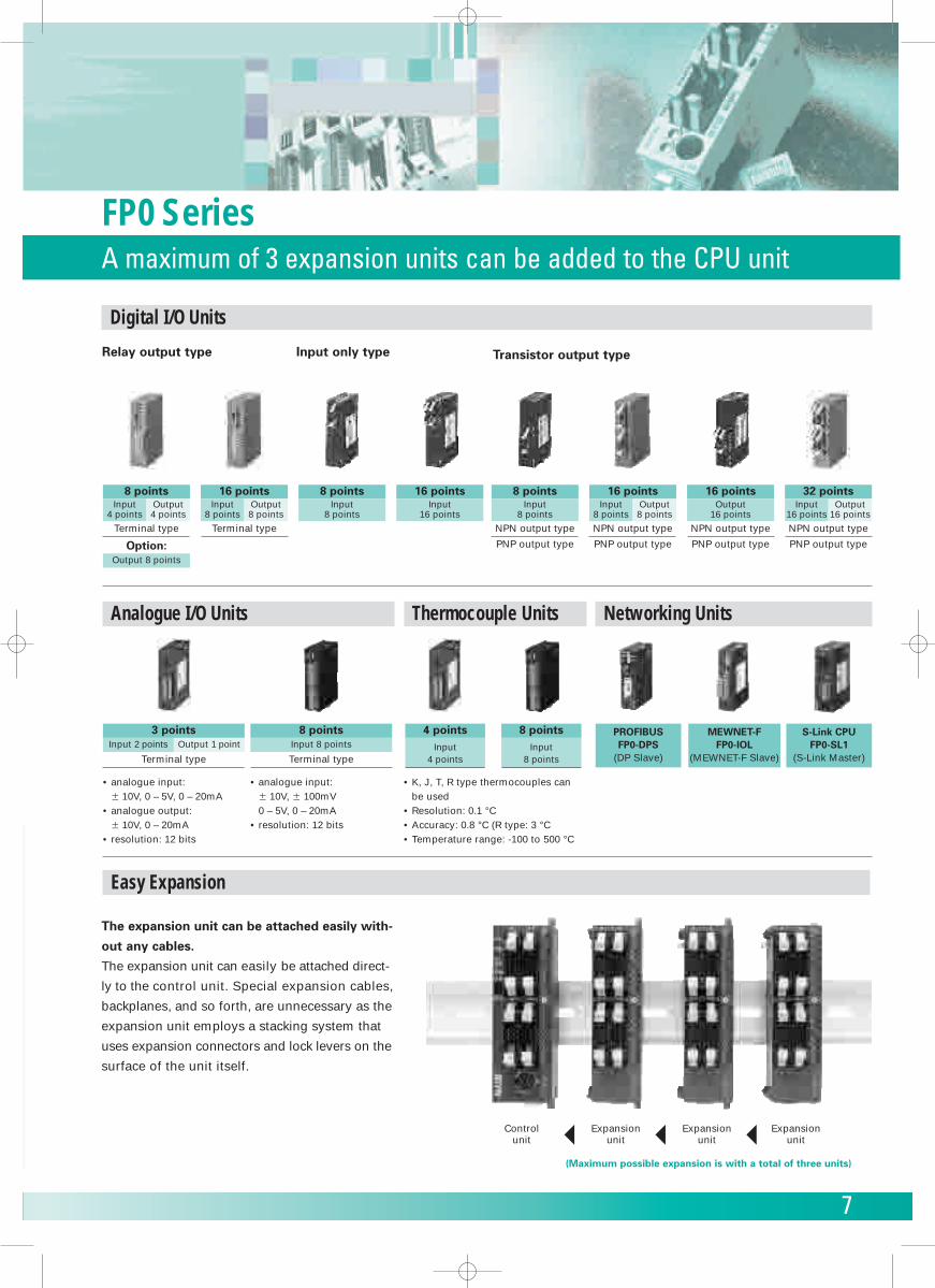
Digital I/O Units
Relay output type Input only type
Terminal typeTerminal type
8 pointsInput
8 points
16 pointsInput
16 points
8 pointsInput
4 points
Option:Output 8 points
Output4 points
16 pointsInput
8 pointsOutput8 points
NPN output type
PNP output type
NPN output type
PNP output type
NPN output type
PNP output type
NPN output type
PNP output type
8 pointsInput
8 points
16 pointsInput
8 pointsOutput8 points
16 pointsOutput
16 points
32 pointsInput
16 pointsOutput
16 points
Analogue I/O Units Thermocouple Units Networking Units
8 points3 pointsInput 8 points
Terminal type
• analogue input:� 10V, 0 – 5V, 0 – 20mA
• analogue output:� 10V, 0 – 20mA
• resolution: 12 bits
• analogue input:� 10V, � 100mV0 – 5V, 0 – 20mA
• resolution: 12 bits
4 pointsInput
4 points
8 pointsInput
8 points
• K, J, T, R type thermocouples canbe used
• Resolution: 0.1 °C• Accuracy: 0.8 °C (R type: 3 °C• Temperature range: -100 to 500 °C
Input 2 points
Terminal type
Output 1 pointPROFIBUSFP0-DPS
(DP Slave)
MEWNET-FFP0-IOL
(MEWNET-F Slave)
S-Link CPUFP0-SL1
(S-Link Master)
Controlunit
Expansionunit
Expansionunit
Expansionunit
(Maximum possible expansion is with a total of three units)
The expansion unit can be attached easily with-
out any cables.
The expansion unit can easily be attached direct-
ly to the control unit. Special expansion cables,
backplanes, and so forth, are unnecessary as the
expansion unit employs a stacking system that
uses expansion connectors and lock levers on the
surface of the unit itself.
FP0 SeriesA maximum of 3 expansion units can be added to the CPU unit
Easy Expansion
8
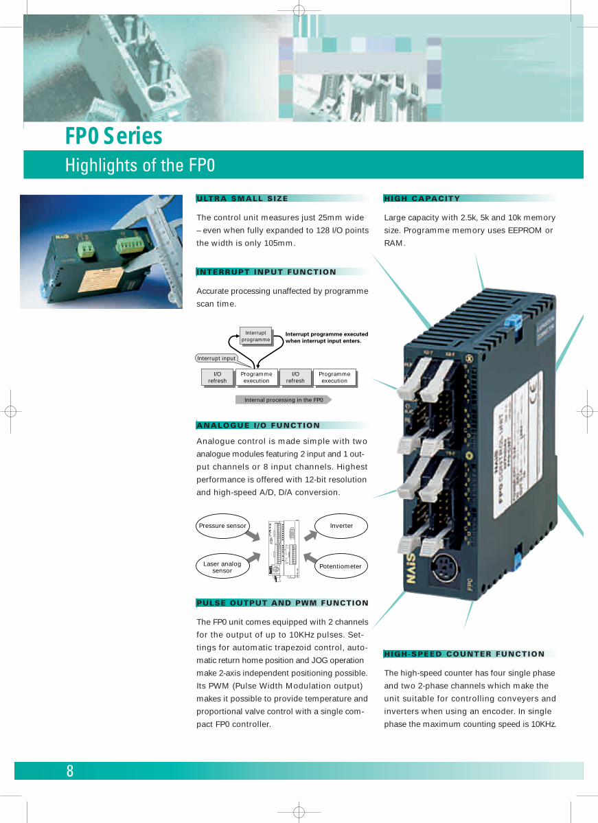
FP0 SeriesHighlights of the FP0
ULTRA SMALL SIZE
The control unit measures just 25mm wide
– even when fully expanded to 128 I/O points
the width is only 105mm.
INTERRUPT INPUT FUNCTION
Accurate processing unaffected by programme
scan time.
ANALOGUE I /O FUNCTION
Analogue control is made simple with two
analogue modules featuring 2 input and 1 out-
put channels or 8 input channels. Highest
performance is offered with 12-bit resolution
and high-speed A/D, D/A conversion.
PULSE OUTPUT AND PWM FUNCTION
The FP0 unit comes equipped with 2 channels
for the output of up to 10KHz pulses. Set-
tings for automatic trapezoid control, auto-
matic return home position and JOG operation
make 2-axis independent positioning possible.
Its PWM (Pulse Width Modulation output)
makes it possible to provide temperature and
proportional valve control with a single com-
pact FP0 controller.
Internal processing in the FP0
I/Orefresh
Programmeexecution
I/Orefresh
Programmeexecution
Interruptprogramme
Interrupt input
Interrupt programme executed when interrupt input enters.
PROG.
RUNALARM
ERROR
PROG
RUNPressure sensor
Laser analogsensor
Inverter
Potentiometer
MODE
OFF ON
V 0
IN
I 0
COM
FP
0 -
A21
OUT
I 1
V
I
12345
HIGH CAPACITY
Large capacity with 2.5k, 5k and 10k memory
size. Programme memory uses EEPROM or
RAM.
HIGH-SPEED COUNTER FUNCTION
The high-speed counter has four single phase
and two 2-phase channels which make the
unit suitable for controlling conveyers and
inverters when using an encoder. In single
phase the maximum counting speed is 10KHz.
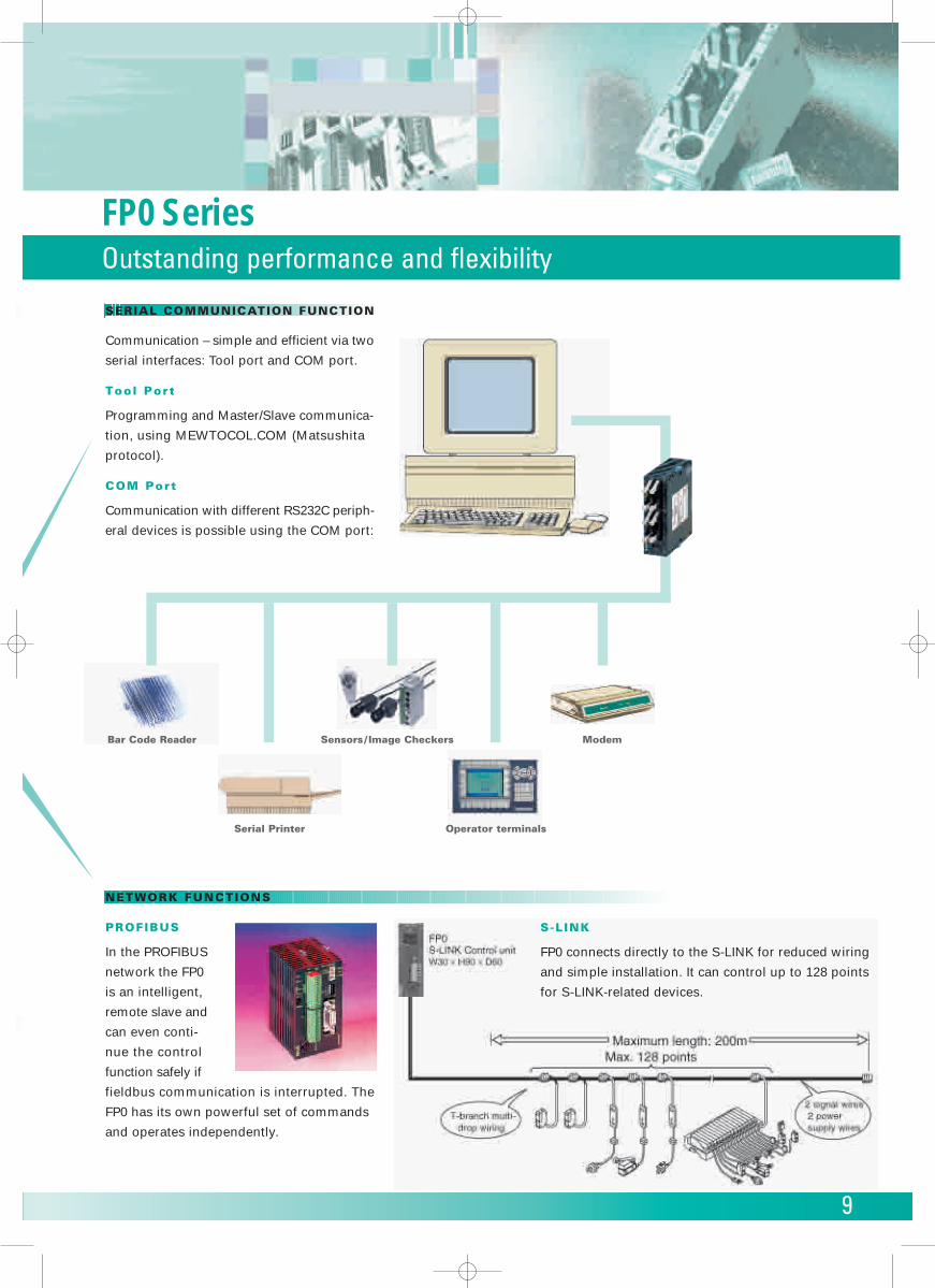
SERIAL COMMUNICATION FUNCTION
Communication – simple and efficient via two
serial interfaces: Tool port and COM port.
Tool Port
Programming and Master/Slave communica-
tion, using MEWTOCOL.COM (Matsushita
protocol).
COM Port
Communication with different RS232C periph-
eral devices is possible using the COM port:
NETWORK FUNCTIONS
PROFIBUS
In the PROFIBUS
network the FP0
is an intelligent,
remote slave and
can even conti-
nue the control
function safely if
fieldbus communication is interrupted. The
FP0 has its own powerful set of commands
and operates independently.
ModemBar Code Reader Sensors / Image Checkers
Operator terminalsSerial Printer
S-L INK
FP0 connects directly to the S-LINK for reduced wiring
and simple installation. It can control up to 128 points
for S-LINK-related devices.
FP0 SeriesOutstanding performance and flexibility
9
10
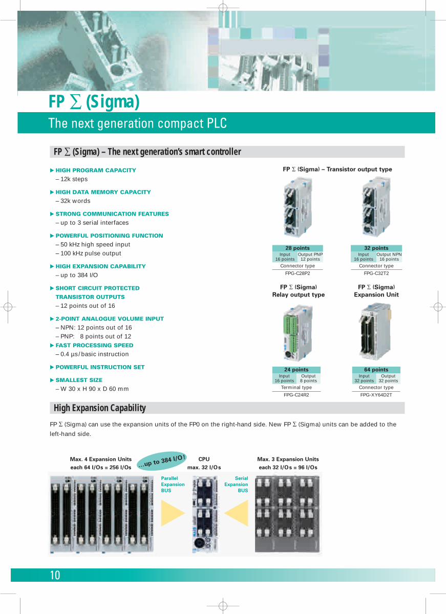
FP ∑ (Sigma)The next generation compact PLC
FP ∑ (Sigma)Relay output type
FP ∑ (Sigma)Expansion Unit
� HIGH PROGRAM CAPACITY
– 12k steps
� HIGH DATA MEMORY CAPACITY
– 32k words
� STRONG COMMUNICATION FEATURES
– up to 3 serial interfaces
� POWERFUL POSITIONING FUNCTION
– 50 kHz high speed input– 100 kHz pulse output
� HIGH EXPANSION CAPABILITY
– up to 384 I/O
� SHORT CIRCUIT PROTECTED
TRANSISTOR OUTPUTS
– 12 points out of 16
� 2-POINT ANALOGUE VOLUME INPUT
– NPN: 12 points out of 16– PNP: 8 points out of 12
� FAST PROCESSING SPEED
– 0.4 µs/ basic instruction
� POWERFUL INSTRUCTION SET
� SMALLEST SIZE
– W 30 x H 90 x D 60 mm
High Expansion Capability
FP ∑ (Sigma) can use the expansion units of the FP0 on the right-hand side. New FP ∑ (Sigma) units can be added to the
left-hand side.
Terminal type
FPG-C24R2
24 pointsInput
16 pointsOutput8 points
Connector type
FPG-XY64D2T
64 pointsInput
32 pointsOutput
32 points
FP ∑ (Sigma) – Transistor output type
Connector type
FPG-C32T2
32 pointsInput
16 pointsOutput NPN
16 points
Connector type
FPG-C28P2
28 pointsInput
16 pointsOutput PNP
12 points
Max. 4 Expansion Unitseach 64 I/Os = 256 I/Os
ParallelExpansionBUS
SerialExpansion
BUS
CPUmax. 32 I/Os
Max. 3 Expansion Unitseach 32 I/Os = 96 I/Os
FP ∑ (Sigma) – The next generation’s smart controller
…up to 384 I/O!
11
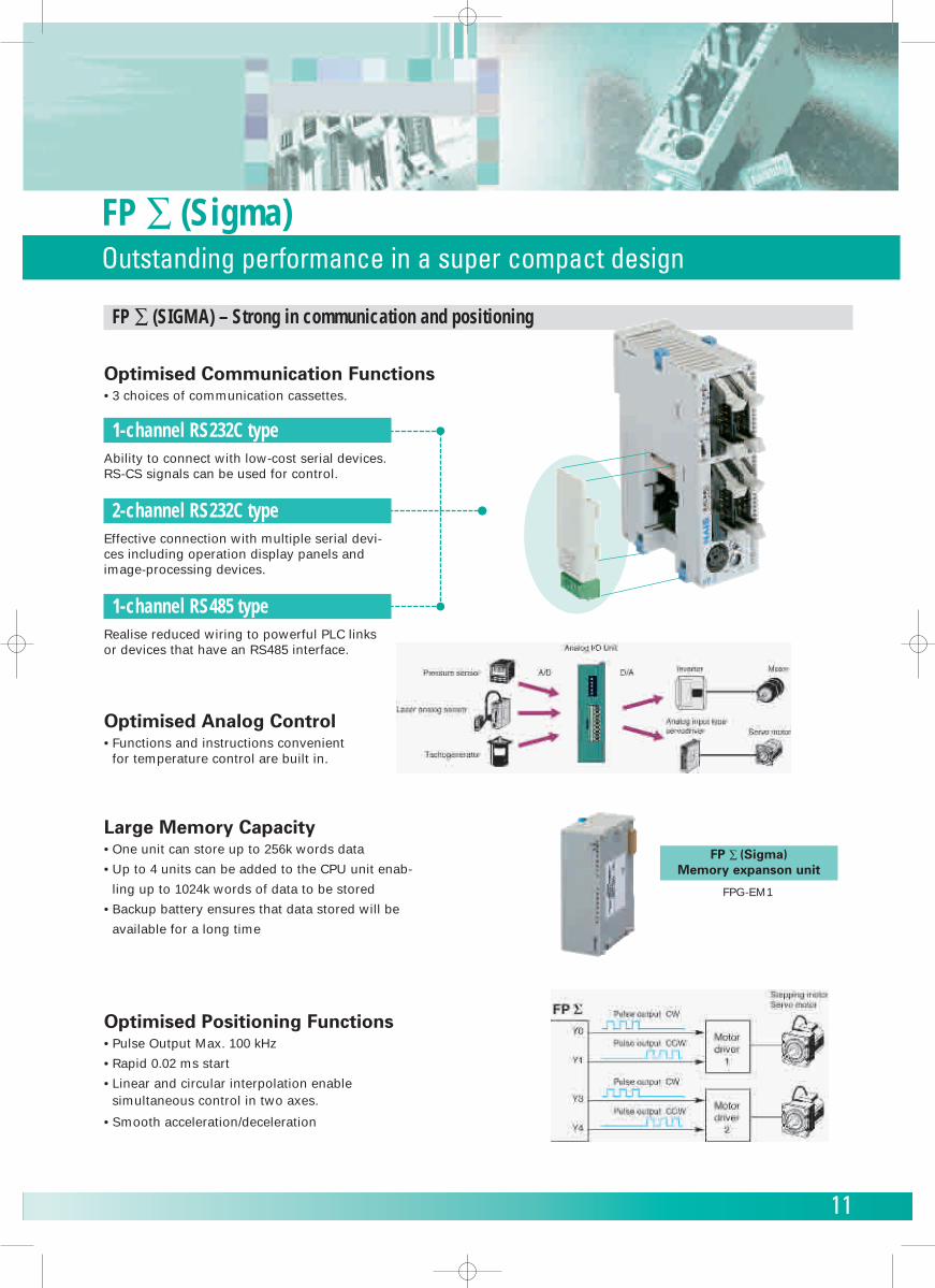
FP ∑ (Sigma)Outstanding performance in a super compact design
Optimised Communication Functions• 3 choices of communication cassettes.
FP ∑ (SIGMA) – Strong in communication and positioning
Large Memory Capacity• One unit can store up to 256k words data
• Up to 4 units can be added to the CPU unit enab-
ling up to 1024k words of data to be stored
• Backup battery ensures that data stored will be
available for a long time
Optimised Positioning Functions• Pulse Output Max. 100 kHz
• Rapid 0.02 ms start
• Linear and circular interpolation enablesimultaneous control in two axes.
• Smooth acceleration/deceleration
1-channel RS232C typeAbility to connect with low-cost serial devices.RS-CS signals can be used for control.
2-channel RS232C typeEffective connection with multiple serial devi-ces including operation display panels andimage-processing devices.
1-channel RS485 typeRealise reduced wiring to powerful PLC linksor devices that have an RS485 interface.
Optimised Analog Control• Functions and instructions convenient
for temperature control are built in.
FP ∑ (Sigma)Memory expanson unit
FPG-EM1
12
Control FPWIN ProPLC Programming Software conforming to IEC61131-3
13
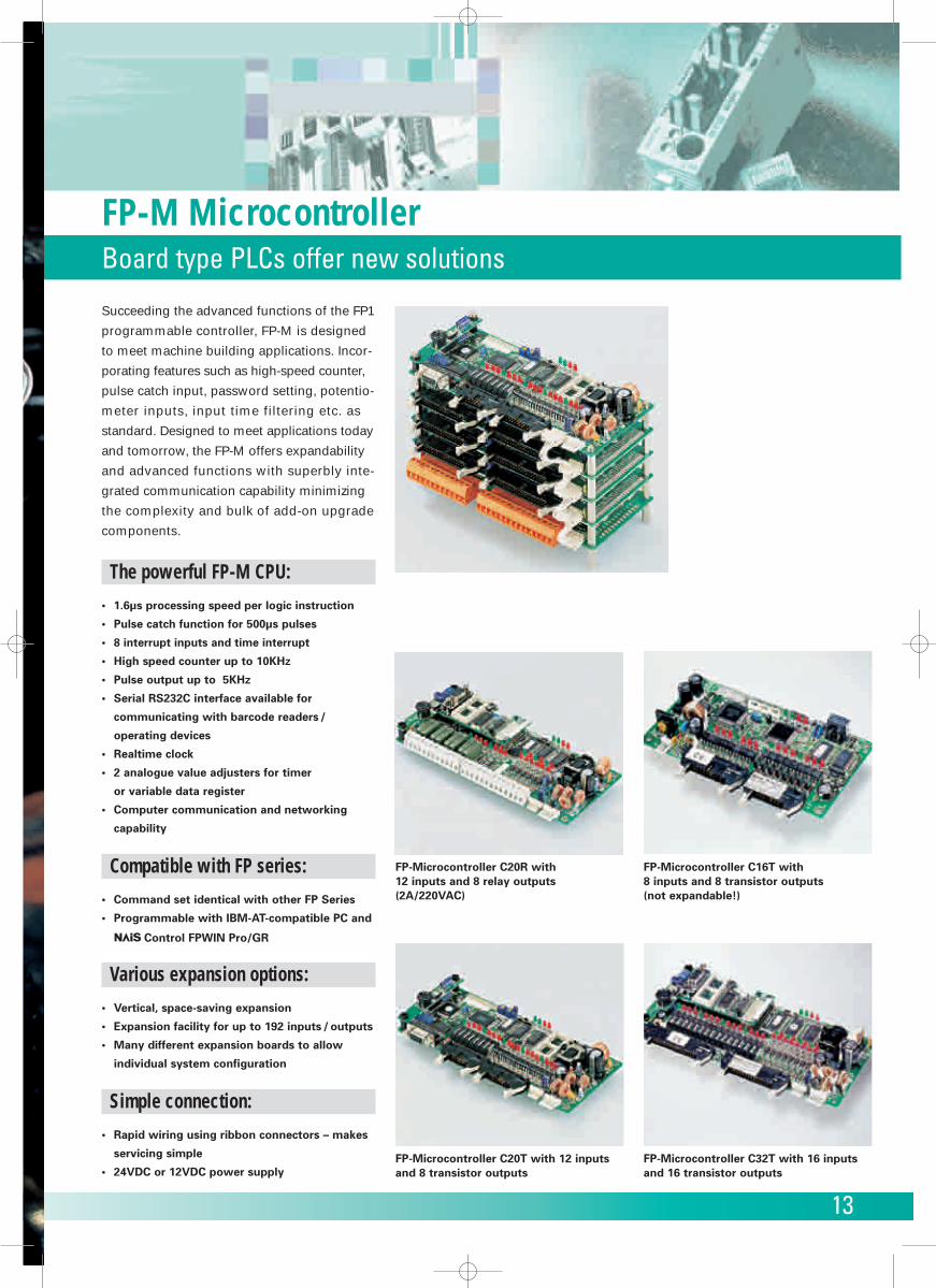
Succeeding the advanced functions of the FP1
programmable controller, FP-M is designed
to meet machine building applications. Incor-
porating features such as high-speed counter,
pulse catch input, password setting, potentio-
meter inputs, input time filtering etc. as
standard. Designed to meet applications today
and tomorrow, the FP-M offers expandability
and advanced functions with superbly inte-
grated communication capability minimizing
the complexity and bulk of add-on upgrade
components.
The powerful FP-M CPU:
• 1.6µs processing speed per logic instruction
• Pulse catch function for 500µs pulses
• 8 interrupt inputs and time interrupt
• High speed counter up to 10KHz
• Pulse output up to 5KHz
• Serial RS232C interface available for
communicating with barcode readers /
operating devices
• Realtime clock
• 2 analogue value adjusters for timer
or variable data register
• Computer communication and networking
capability
Compatible with FP series:
• Command set identical with other FP Series
• Programmable with IBM-AT-compatible PC and
Control FPWIN Pro/GR
Various expansion options:
• Vertical, space-saving expansion
• Expansion facility for up to 192 inputs / outputs
• Many different expansion boards to allow
individual system configuration
Simple connection:
• Rapid wiring using ribbon connectors – makes
servicing simple
• 24VDC or 12VDC power supply
FP-Microcontroller C20R with 12 inputs and 8 relay outputs(2A/220VAC)
FP-Microcontroller C20T with 12 inputsand 8 transistor outputs
FP-Microcontroller C16T with 8 inputs and 8 transistor outputs (not expandable!)
FP-Microcontroller C32T with 16 inputsand 16 transistor outputs
FP-M MicrocontrollerBoard type PLCs offer new solutions
14
FP-M MicrocontrollerExpansion options
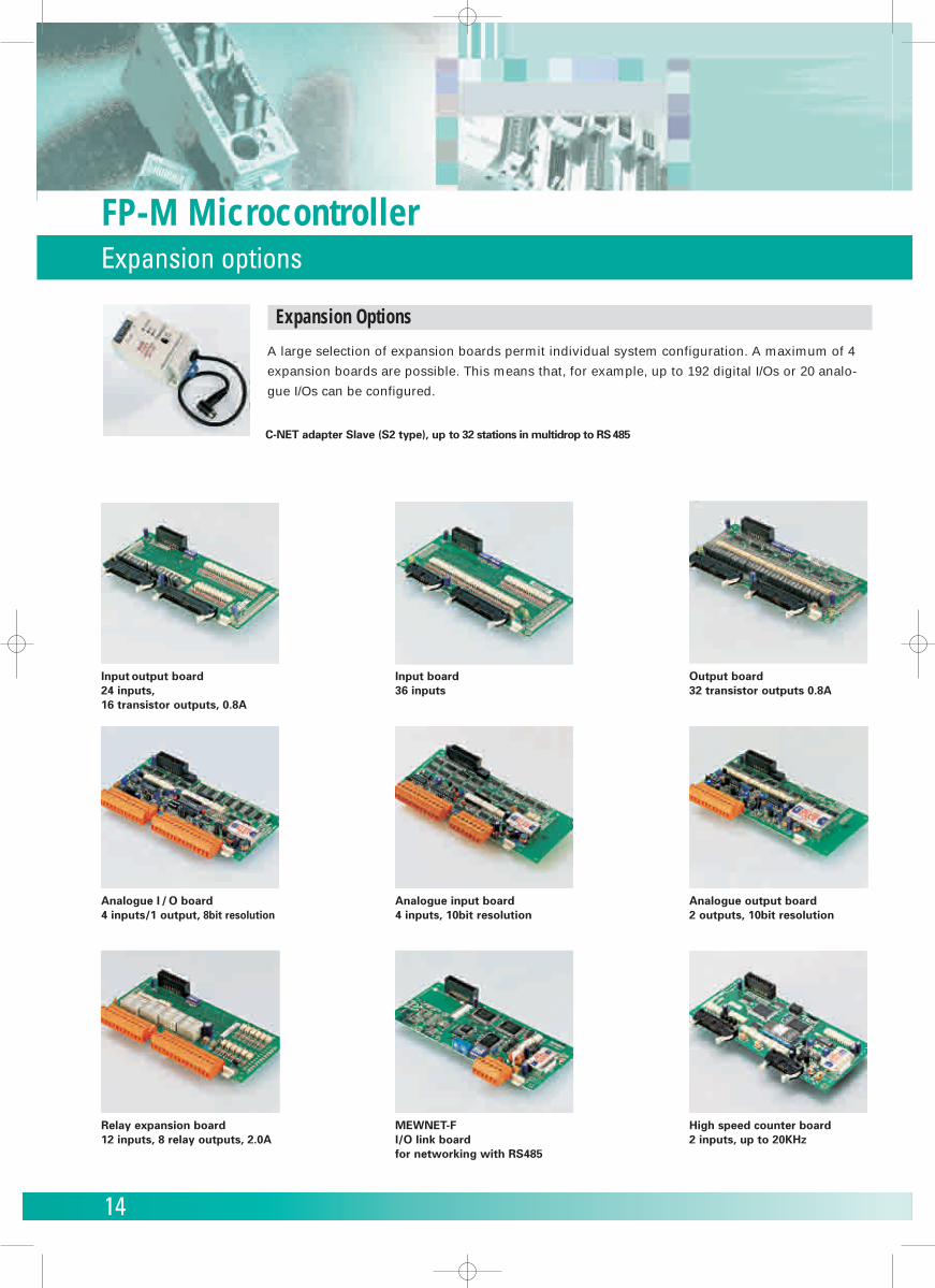
Expansion Options
A large selection of expansion boards permit individual system configuration. A maximum of 4
expansion boards are possible. This means that, for example, up to 192 digital I/Os or 20 analo-
gue I/Os can be configured.
Input output board 24 inputs, 16 transistor outputs, 0.8A
Analogue I / O board4 inputs/1 output, 8bit resolution
C-NET adapter Slave (S2 type), up to 32 stations in multidrop to RS485
Input board36 inputs
Analogue input board4 inputs, 10bit resolution
MEWNET-FI/O link boardfor networking with RS485
Output board32 transistor outputs 0.8A
Analogue output board2 outputs, 10bit resolution
High speed counter board2 inputs, up to 20KHz
Relay expansion board12 inputs, 8 relay outputs, 2.0A
15
FP-M MicrocontrollerSpecifications
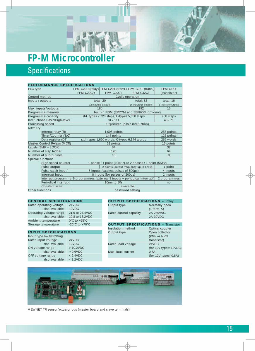
PERFORMANCE SPECIFICATIONSPLC type FPM C20R (relay) FPM C20T (trans.) FPM C32T (trans.) FPM C16T
FPM C20CR FPM C20CT FPM C32CT (transistor)Control method Cyclic operationInputs / outputs total: 20 total: 32 total: 16
12 inputs/8 outputs 16 inputs/16 outputs 8 inputs/8 outputs
Max. inputs/outputs: 180 192 16Programme memory built-in ROM (EPROM and EEPROM optional)Programme capacity std. types 2,720 steps, C-types 5,000 steps 900 stepsInstructions Basic/High-level 81 / 111 43 / 71Processing speed 1.6µs/step (basic instruction)Memory
Internal relay (R) 1,008 points 256 pointsTimer/Counter (T/C) 144 points 128 pointsData register (DT) std. types 1,660 words, C-types 6,144 words 256 words
Master Control Relays (MCR) 32 points 16 pointsLabels (JMP + LOOP) 64 32Number of step ladder 128 64Number of subroutines 16 8Special functions
High speed counter 1 phase / 1 point (10KHz) or 2 phases / 1 point (5KHz)Pulse output 2 points (output frequency up to 5KHz) 1 pointPulse catch input/ 8 inputs (catches pulses of 500µs) 4 inputsInterrupt input 8 inputs (for pulses of 200µs) 2 inputsInterrupt programme 9 programmes (external 8 inputs + periodical interrupt) 2 programmesPeriodical interrupt 10ms to 30s noConstant scan available
Other functions password setting
OUTPUT SPECIFICATIONS – RelayOutput type Normally open
(1 form A)Rated control capacity 2A 250VAC,
2A 30VDC
OUTPUT SPECIFICATIONS – TransistorInsulation method Optical couplerOutput type Open collector
(PNP or NPNtransistor)
Rated load voltage 24VDC (for 12V types: 12VDC)
Max. load current 0.8A(for 12V types: 0.8A)
GENERAL SPECIFICATIONSRated operating voltage 24VDC
also available 12VDCOperating voltage range 21.6 to 26.4VDC
also available 10.8 to 13.2VDCAmbient temperature 0°C to +55°CStorage temperature -20°C to +70°C
INPUT SPECIFICATIONSInput type +/– switchingRated input voltage 24VDC
also available 12VDCON voltage range > 19.2VDC
also available > 9.6VDCOFF voltage range < 2.4VDC
also available < 1.2VDC
MEWNET TR sensor/actuator bus (master board and slave terminals)
16
Control FPWIN ProPLC Programming Software conforming to IEC61131-3
17
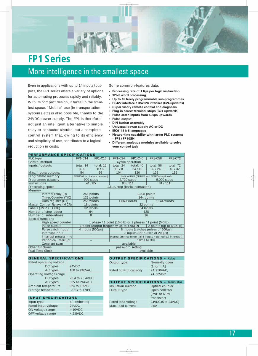
FP1 SeriesMore intelligence in the smallest space
PERFORMANCE SPECIFICATIONSPLC type FP1-C14 FP1-C16 FP1-C24 FP1-C40 FP1-C56 FP1-C72Control method Cyclic operationInputs / outputs total: 14 total: 16 total: 24 total: 40 total: 56 total: 72
8 / 6 8 / 8 16 / 8 24 / 16 32 / 24 40 / 32Max. inputs/outputs: 54 56 104 120 136 152Programme memory EEPROM (no battery required) built in ROM (EPROM and EEPROM optional)Programme capacity 900 steps 2,720 steps 5,000 stepsInstructions 41 / 85 80 / 111 81 / 111Processing speed 1.6µs/step (basic instruction)Memory
Internal relay (R) 256 points 1,008 pointsTimer/Counter (T/C) 128 points 144 pointsData register (DT) 256 words 1,660 words 6,144 words
Master Control Relays (MCR) 16 points 32 pointsLabels (JMP + LOOP) 32 labels 64 labelsNumber of step ladder 64 128Number of subroutines 8 16Special functions
High speed counter 1 phase / 1 point (10KHz) or 2 phases / 1 point (5KHz)Pulse output 1 point (output frequency up to 4.9KHz) 2 points (up to 4.9KHz)Pulse catch input/ 4 inputs (500µs) 8 inputs (catches pulses of 500µs)Interrupt input – 8 inputs (for pulses of 200µs)Interrupt programme – 9 programmes (external 6 inputs + periodical interrupt)Periodical interrupt – 10ms to 30sConstant scan available
Other functions password settingReal Time Clock – available
OUTPUT SPECIFICATIONS – RelayOutput type Normally open
(1 form A)Rated control capacity 2A 250VAC,
2A 30VDC
OUTPUT SPECIFICATIONS – TransistorInsulation method Optical couplerOutput type Open collector
(PNP or NPNtransistor)
Rated load voltage 24VDC (5 to 24VDC)Max. load current 0.5A
GENERAL SPECIFICATIONSRated operating voltage
DC types: 24VDCAC types: 100 to 240VAC
Operating voltage rangeDC types: 20.4 to 26.4VDCAC types: 85V to 264VAC
Ambient temperature 0°C to +55°CStorage temperature -20°C to +70°C
INPUT SPECIFICATIONSInput type +/– switchingRated input voltage 24VDCON voltage range > 10VDCOFF voltage range < 2.5VDC
Even in applications with up to 14 inputs / out-
puts, the FP1 series offers a variety of options
for automating processes rapidly and reliably.
With its compact design, it takes up the smal-
lest space. ”Mobile“ use (in transportation
systems etc) is also possible, thanks to the
24VDC power supply. The FP1 is therefore
not just an intelligent alternative to simple
relay or contactor circuits, but a complete
control system that, owing to its efficiency
and simplicity of use, contributes to a logical
reduction in costs.
Some common-features data:
• Processing rate of 1.6µs per logic instruction• 32bit word processing• Up to 16 freely programmable sub-programmes• RS422 interface / RS232C interface (C24 upwards)• Super visory remote control and diagnosis• Plug-in screw terminal strips (C24 upwards)• Pulse catch inputs from 500µs upwards• Pulse output• DIN busbar assembly• Universal power supply AC or DC• IEC61131: 5 languages• Networking capability with larger PLC systems
– FP3 / FP10SH• Different analogue modules available to solve
your control task
18
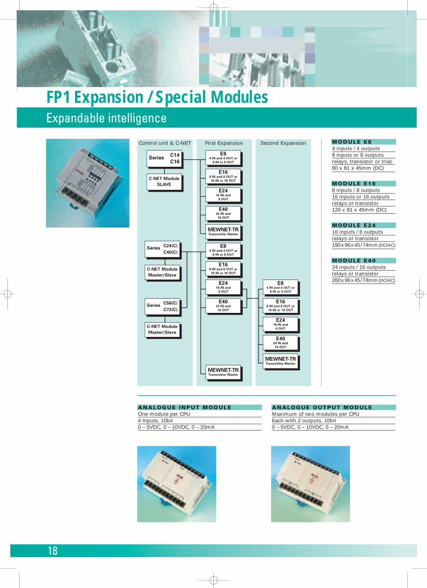
FP1 Expansion / Special ModulesExpandable intelligence
Control unit & C-NET First Expansion Second Expansion
Series C14C16
C-NET ModuleSLAVE
Series C24(C)C40(C)
C-NET ModuleMaster/Slave
Series C56(C)C72(C)
C-NET ModuleMaster/Slave
E84 IN and 4 OUT or
8 IN or 8 OUT
E168 IN and 8 OUT or16 IN or 16 OUT
E2416 IN and
8 OUT
E4024 IN and16 OUT
MEWNET-TRTransmitter Master
MEWNET-TRTransmitter Master
E84 IN and 4 OUT or
8 IN or 8 OUT
E168 IN and 8 OUT or16 IN or 16 OUT
E2416 IN and
8 OUT
E4024 IN and16 OUT
E84 IN and 4 OUT or
8 IN or 8 OUT
E168 IN and 8 OUT or16 IN or 16 OUT
E2416 IN and
8 OUT
E4024 IN and16 OUT
MEWNET-TRTransmitter Master
MODULE E8 4 inputs / 4 outputs8 inputs or 8 outputsrelays, transistor or triac80 x 81 x 45mm (DC)
MODULE E16 8 inputs / 8 outputs16 inputs or 16 outputsrelays or transistor120 x 81 x 45mm (DC)
MODULE E24 16 inputs / 8 outputsrelays or transistor190x96x45/74mm(DC/AC)
MODULE E40 24 inputs / 16 outputsrelays or transistor260x96x45/74mm(DC/AC)
ANALOGUE INPUT MODULE One module per CPU4 Inputs, 10bit0 – 5VDC, 0 – 10VDC, 0 – 20mA
ANALOGUE OUTPUT MODULE Maximum of two modules per CPUEach with 2 outputs, 10bit0 – 5VDC, 0 – 10VDC, 0 – 20mA
19
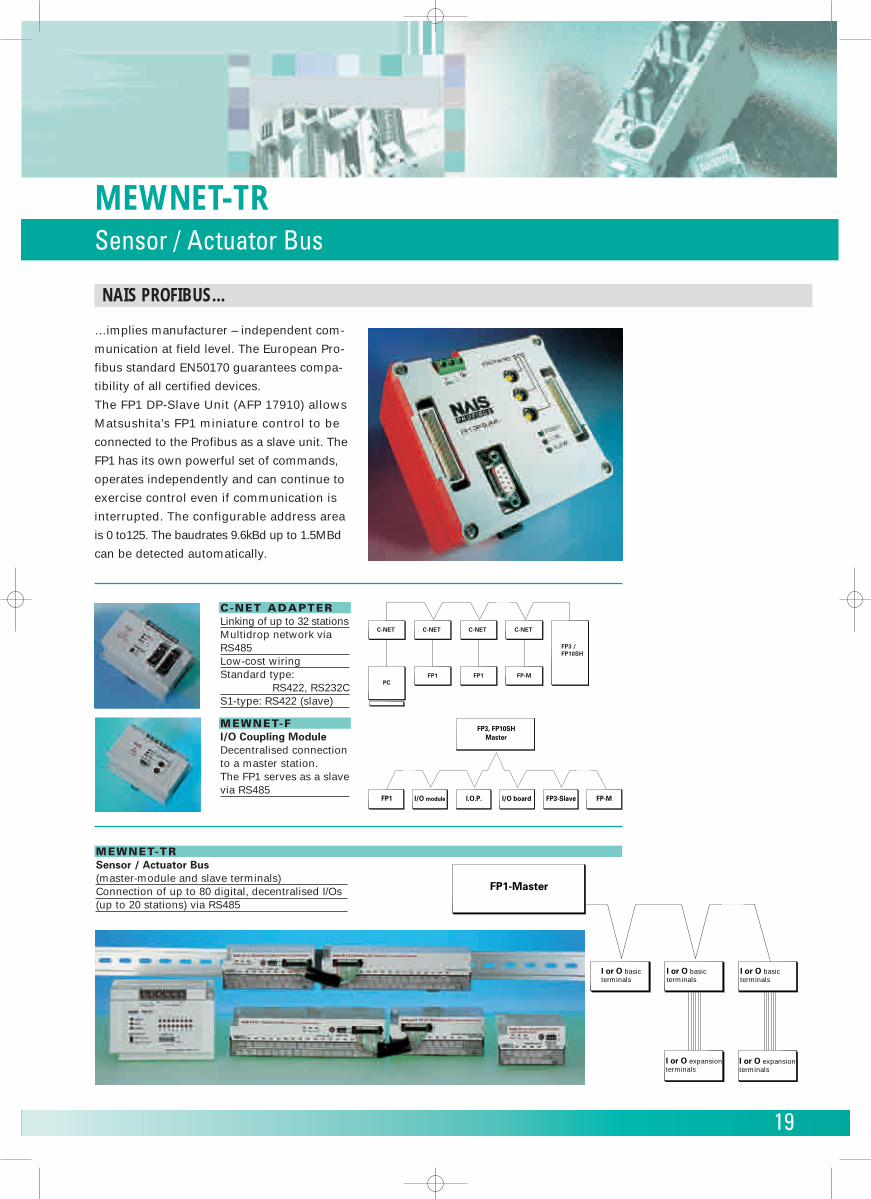
MEWNET-TRSensor / Actuator Bus
C-NET C-NET C-NET C-NET
FP1PC
FP1 FP-M
FP3 /FP10SH
FP1 I/O module I.O.P.
FP3, FP10SHMaster
I/O board FP3-Slave FP-M
C-NET ADAPTER Linking of up to 32 stationsMultidrop network viaRS485Low-cost wiringStandard type:
RS422, RS232CS1-type: RS422 (slave)
MEWNET-F I/O Coupling ModuleDecentralised connectionto a master station. The FP1 serves as a slavevia RS485
MEWNET-TR Sensor / Actuator Bus(master-module and slave terminals)Connection of up to 80 digital, decentralised I/Os(up to 20 stations) via RS485
FP1-Master
I or O basic terminals
I or O expansion terminals
I or O expansion terminals
I or O basic terminals
I or O basic terminals
…implies manufacturer – independent com-
munication at field level. The European Pro-
fibus standard EN50170 guarantees compa-
tibility of all certified devices.
The FP1 DP-Slave Unit (AFP 17910) allows
Matsushita’s FP1 miniature control to be
connected to the Profibus as a slave unit. The
FP1 has its own powerful set of commands,
operates independently and can continue to
exercise control even if communication is
interrupted. The configurable address area
is 0 to125. The baudrates 9.6kBd up to 1.5MBd
can be detected automatically.
NAIS PROFIBUS…
20
Control FPWIN ProPLC Programming Software conforming to IEC61131-3
21
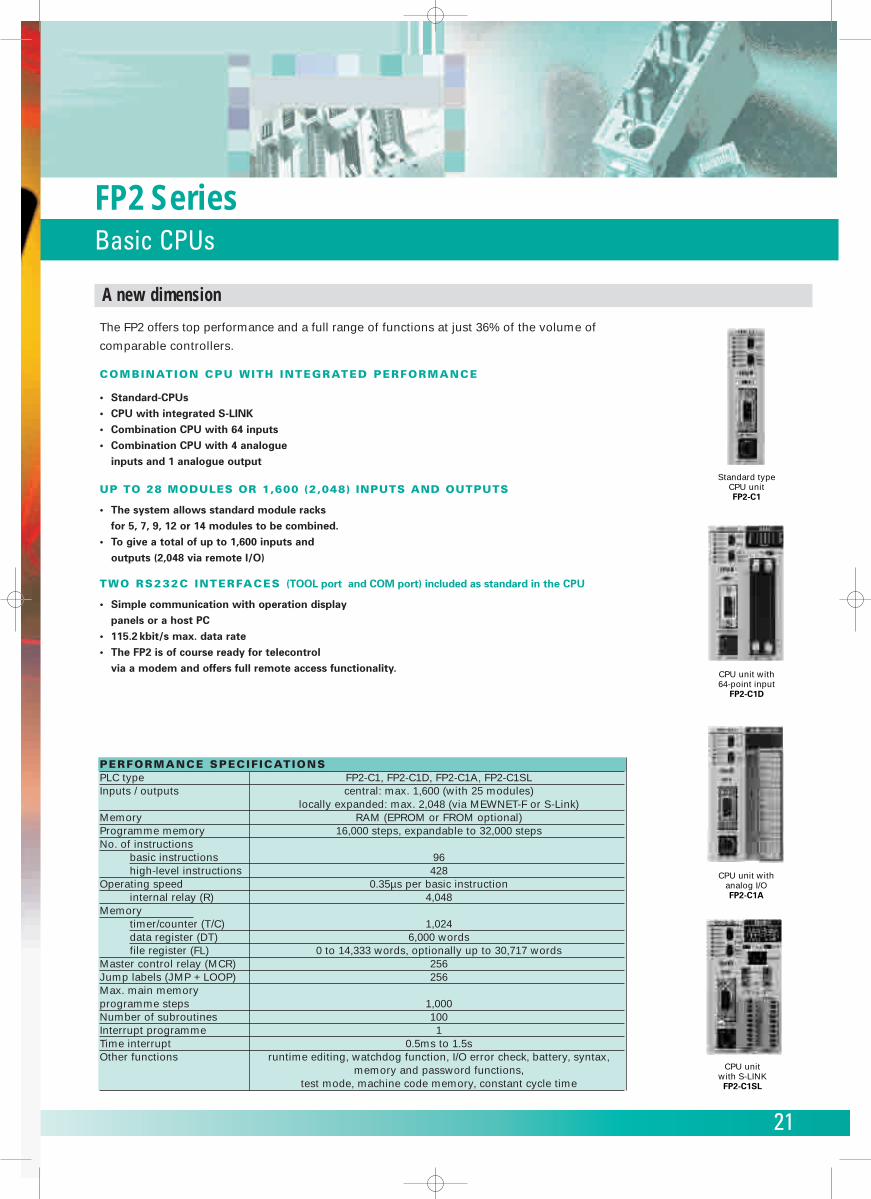
FP2 SeriesBasic CPUs
The FP2 offers top performance and a full range of functions at just 36% of the volume of
comparable controllers.
COMBINATION CPU WITH INTEGRATED PERFORMANCE
• Standard-CPUs• CPU with integrated S-LINK• Combination CPU with 64 inputs • Combination CPU with 4 analogue
inputs and 1 analogue output
UP TO 28 MODULES OR 1,600 (2,048) INPUTS AND OUTPUTS
• The system allows standard module racks for 5, 7, 9, 12 or 14 modules to be combined.
• To give a total of up to 1,600 inputs and outputs (2,048 via remote I/O)
TWO RS232C INTERFACES (TOOL port and COM port) included as standard in the CPU
• Simple communication with operation display panels or a host PC
• 115.2 kbit/s max. data rate • The FP2 is of course ready for telecontrol
via a modem and offers full remote access functionality.
PERFORMANCE SPECIFICATIONSPLC type FP2-C1, FP2-C1D, FP2-C1A, FP2-C1SLInputs / outputs central: max. 1,600 (with 25 modules)
locally expanded: max. 2,048 (via MEWNET-F or S-Link)Memory RAM (EPROM or FROM optional)Programme memory 16,000 steps, expandable to 32,000 stepsNo. of instructions
basic instructions 96high-level instructions 428
Operating speed 0.35µs per basic instructioninternal relay (R) 4,048
Memorytimer/counter (T/C) 1,024data register (DT) 6,000 wordsfile register (FL) 0 to 14,333 words, optionally up to 30,717 words
Master control relay (MCR) 256Jump labels (JMP + LOOP) 256Max. main memoryprogramme steps 1,000Number of subroutines 100Interrupt programme 1Time interrupt 0.5ms to 1.5sOther functions runtime editing, watchdog function, I/O error check, battery, syntax,
memory and password functions,test mode, machine code memory, constant cycle time
Standard typeCPU unitFP2-C1
CPU unit with64-point input
FP2-C1D
CPU unit withanalog I/OFP2-C1A
CPU unitwith S-LINKFP2-C1SL
A new dimension
22
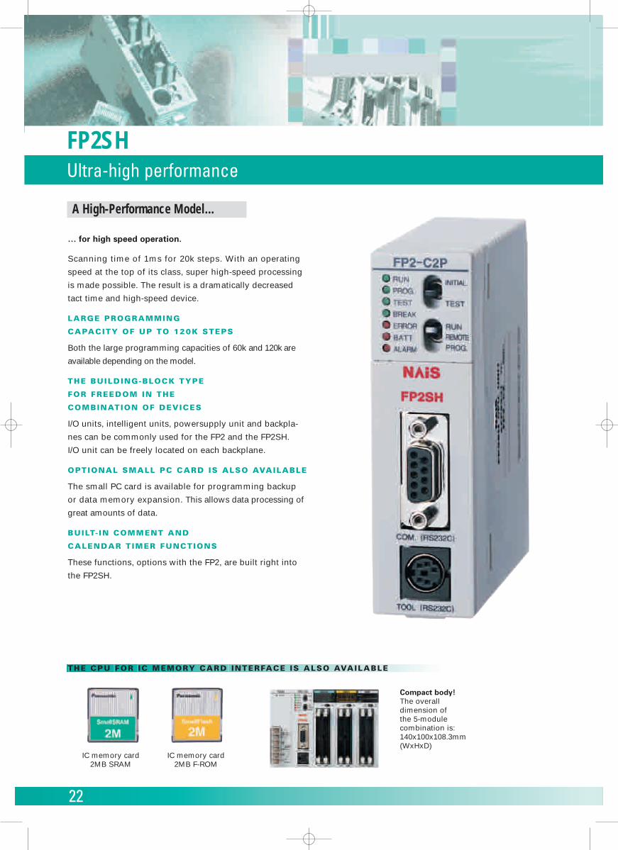
FP2SHUltra-high performance
IC memory card2MB SRAM
IC memory card2MB F-ROM
Compact body!The overall dimension of the 5-module combination is:140x100x108.3mm(WxHxD)
A High-Performance Model…
… for high speed operation.
Scanning time of 1ms for 20k steps. With an operating
speed at the top of its class, super high-speed processing
is made possible. The result is a dramatically decreased
tact time and high-speed device.
LARGE PROGRAMMING
CAPACITY OF UP TO 120K STEPS
Both the large programming capacities of 60k and 120k are
available depending on the model.
THE BUILDING-BLOCK TYPE
FOR FREEDOM IN THE
COMBINATION OF DEVICES
I/O units, intelligent units, powersupply unit and backpla-
nes can be commonly used for the FP2 and the FP2SH.
I/O unit can be freely located on each backplane.
OPTIONAL SMALL PC CARD IS ALSO AVAILABLE
The small PC card is available for programming backup
or data memory expansion. This allows data processing of
great amounts of data.
BUILT- IN COMMENT AND
CALENDAR TIMER FUNCTIONS
These functions, options with the FP2, are built right into
the FP2SH.
THE CPU FOR IC MEMORY CARD INTERFACE IS ALSO AVAILABLE
23
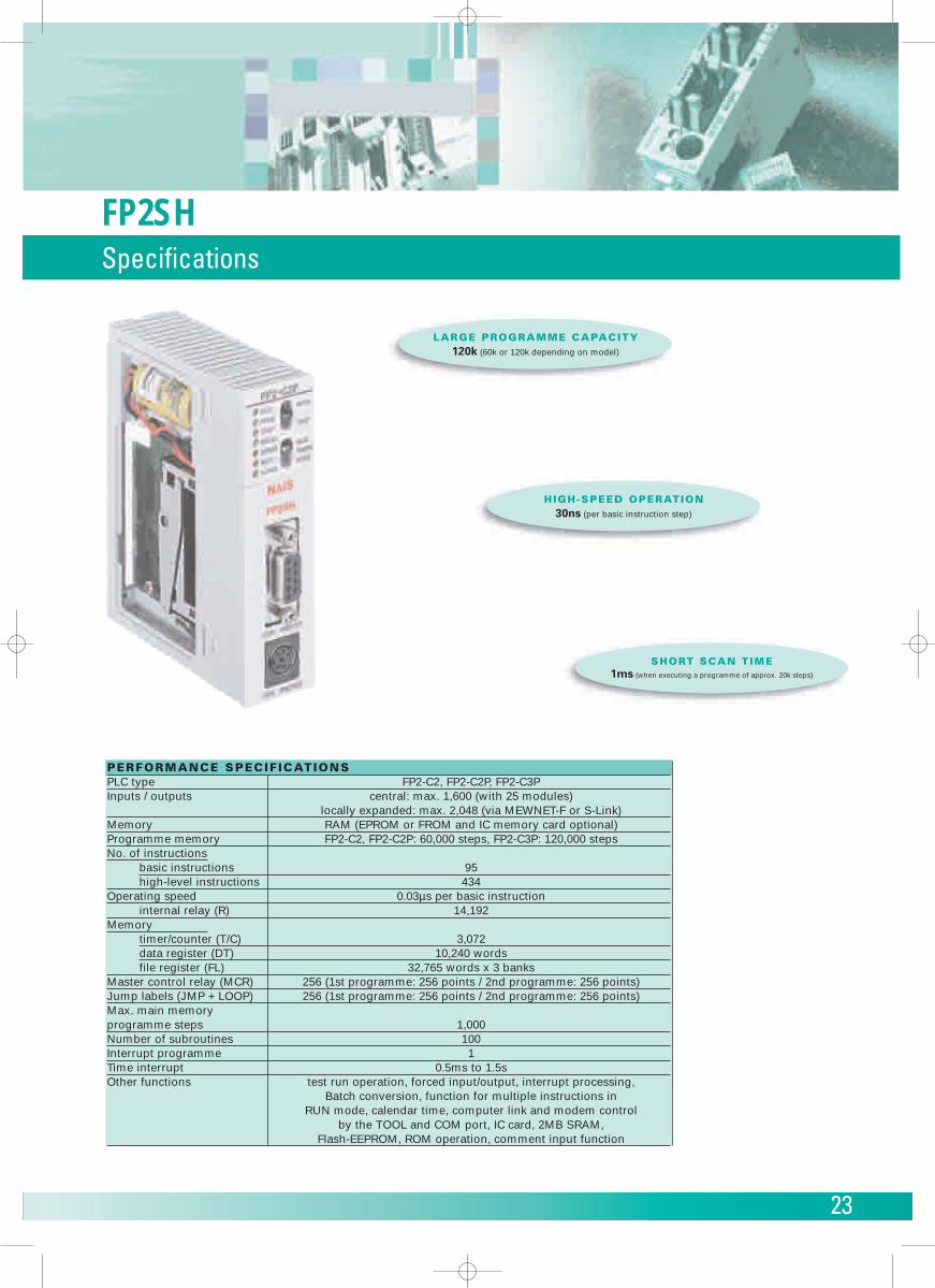
FP2SHSpecifications
SHORT SCAN TIME1ms (when executing a programme of approx. 20k steps)
HIGH-SPEED OPERATION30ns (per basic instruction step)
PERFORMANCE SPECIFICATIONSPLC type FP2-C2, FP2-C2P, FP2-C3PInputs / outputs central: max. 1,600 (with 25 modules)
locally expanded: max. 2,048 (via MEWNET-F or S-Link)Memory RAM (EPROM or FROM and IC memory card optional)Programme memory FP2-C2, FP2-C2P: 60,000 steps, FP2-C3P: 120,000 stepsNo. of instructions
basic instructions 95high-level instructions 434
Operating speed 0.03µs per basic instructioninternal relay (R) 14,192
Memorytimer/counter (T/C) 3,072data register (DT) 10,240 wordsfile register (FL) 32,765 words x 3 banks
Master control relay (MCR) 256 (1st programme: 256 points / 2nd programme: 256 points)Jump labels (JMP + LOOP) 256 (1st programme: 256 points / 2nd programme: 256 points)Max. main memoryprogramme steps 1,000Number of subroutines 100Interrupt programme 1Time interrupt 0.5ms to 1.5sOther functions test run operation, forced input/output, interrupt processing,
Batch conversion, function for multiple instructions in RUN mode, calendar time, computer link and modem control
by the TOOL and COM port, IC card, 2MB SRAM,Flash-EEPROM, ROM operation, comment input function
LARGE PROGRAMME CAPACITY120k (60k or 120k depending on model)
24
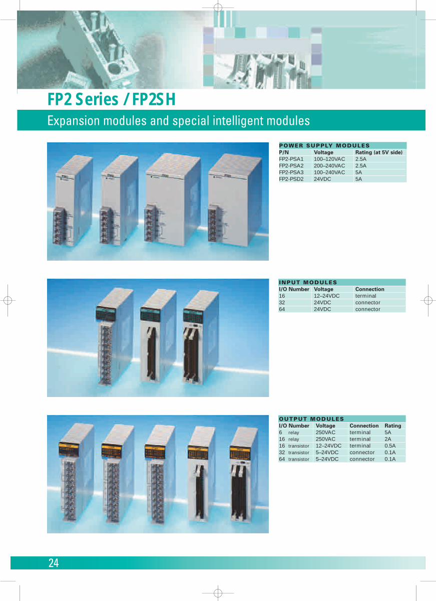
FP2 Series / FP2SHExpansion modules and special intelligent modules
POWER SUPPLY MODULESP/N Voltage Rating (at 5V side)FP2-PSA1 100–120VAC 2.5AFP2-PSA2 200–240VAC 2.5AFP2-PSA3 100–240VAC 5AFP2-PSD2 24VDC 5A
INPUT MODULESI/O Number Voltage Connection16 12–24VDC terminal32 24VDC connector64 24VDC connector
OUTPUT MODULESI/O Number Voltage Connection Rating6 relay 250VAC terminal 5A16 relay 250VAC terminal 2A16 transistor 12–24VDC terminal 0.5A32 transistor 5–24VDC connector 0.1A64 transistor 5–24VDC connector 0.1A
25
FP2 Series / FP2SHExpansion modules and special intelligent modules
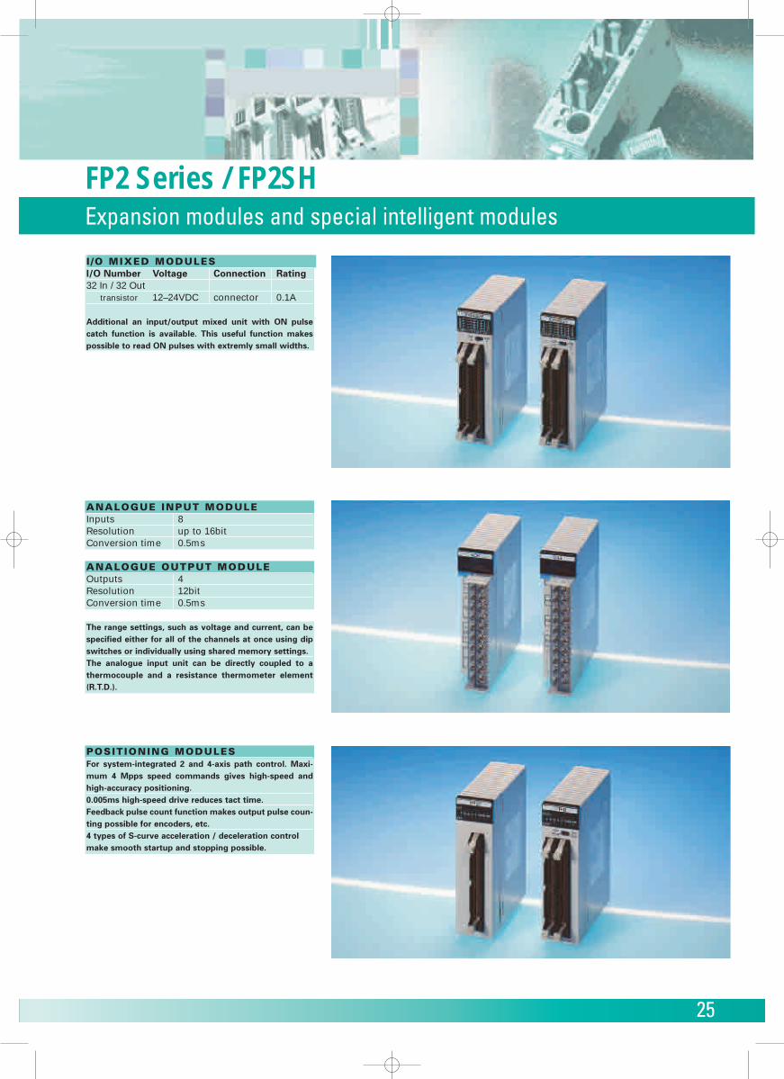
I /O MIXED MODULESI/O Number Voltage Connection Rating32 In / 32 Out
transistor 12–24VDC connector 0.1A
Additional an input/output mixed unit with ON pulsecatch function is available. This useful function makespossible to read ON pulses with extremly small widths.
ANALOGUE INPUT MODULEInputs 8Resolution up to 16bitConversion time 0.5ms
ANALOGUE OUTPUT MODULEOutputs 4Resolution 12bitConversion time 0.5ms
The range settings, such as voltage and current, can bespecified either for all of the channels at once using dipswitches or individually using shared memory settings.The analogue input unit can be directly coupled to a thermocouple and a resistance thermometer element(R.T.D.).
POSITIONING MODULESFor system-integrated 2 and 4-axis path control. Maxi-mum 4 Mpps speed commands gives high-speed andhigh-accuracy positioning.0.005ms high-speed drive reduces tact time.Feedback pulse count function makes output pulse coun-ting possible for encoders, etc.4 types of S-curve acceleration / deceleration controlmake smooth startup and stopping possible.
26
FP2 Series / FP2SHExpansion modules and special intelligent modules
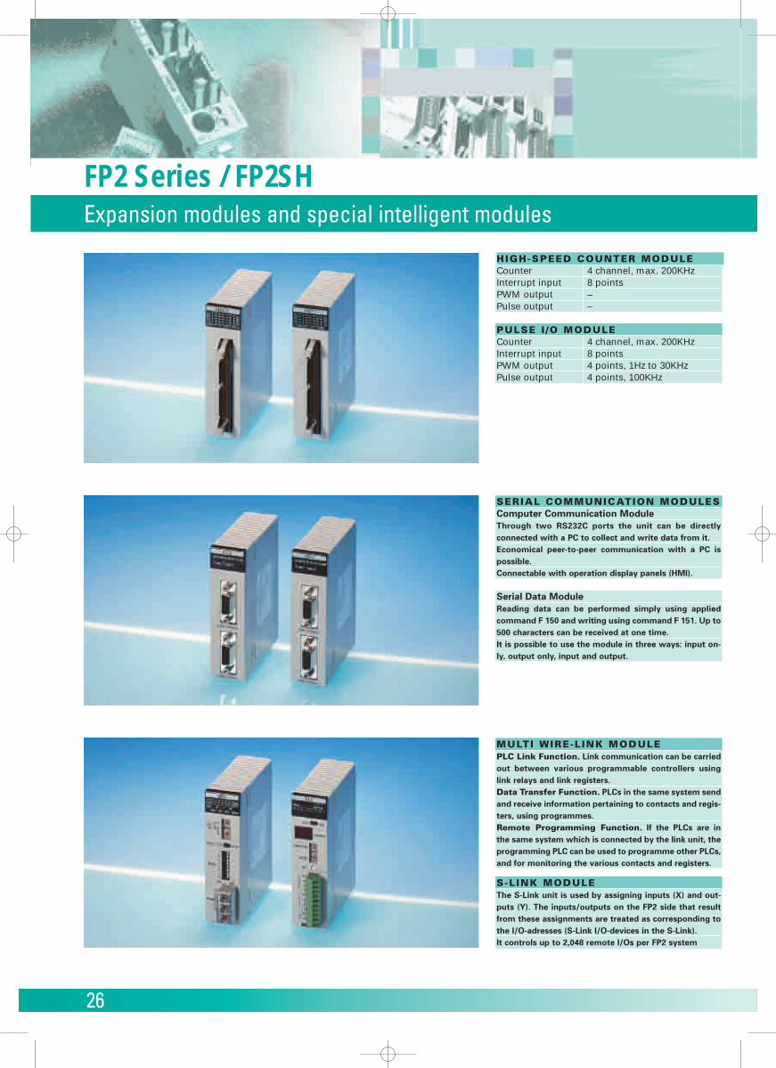
HIGH-SPEED COUNTER MODULECounter 4 channel, max. 200KHzInterrupt input 8 pointsPWM output –Pulse output –
PULSE I /O MODULECounter 4 channel, max. 200KHzInterrupt input 8 pointsPWM output 4 points, 1Hz to 30KHzPulse output 4 points, 100KHz
SERIAL COMMUNICATION MODULESComputer Communication ModuleThrough two RS232C ports the unit can be directly connected with a PC to collect and write data from it.Economical peer-to-peer communication with a PC ispossible.Connectable with operation display panels (HMI).
Serial Data ModuleReading data can be performed simply using appliedcommand F 150 and writing using command F 151. Up to500 characters can be received at one time.It is possible to use the module in three ways: input on-ly, output only, input and output.
MULTI WIRE-L INK MODULEPLC Link Function. Link communication can be carriedout between various programmable controllers usinglink relays and link registers.Data Transfer Function. PLCs in the same system sendand receive information pertaining to contacts and regis-ters, using programmes.Remote Programming Function. If the PLCs are in the same system which is connected by the link unit, theprogramming PLC can be used to programme other PLCs,and for monitoring the various contacts and registers.
S-LINK MODULEThe S-Link unit is used by assigning inputs (X) and out-puts (Y). The inputs/outputs on the FP2 side that resultfrom these assignments are treated as corresponding tothe I/O-adresses (S-Link I/O-devices in the S-Link).It controls up to 2,048 remote I/Os per FP2 system
27
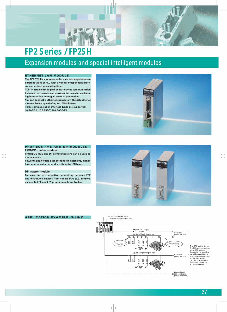
ETHERNET-LAN MODULEThe FP2 ET-LAN module enables data exchange betweendifferent types of PLC with a vendor independent proto-col and a short processing time.TCP/IP establishes logical point-to-point communicationbetween two devices and provides the basis for exchang-ing information among all areas of production.You can connect 8 Ethernet segments with each other ata transmission speed of up to 100Mbits/sec.Three communication interface types are supported:10 BASE 5, 10 BASE-T, 100 BASE-TX
PROFIBUS FMS AND DP MODULESFMS/DP master modulePROFIBUS FMS and DP communications can be used si-multaneously.Powerful and flexible data exchange in extensive, higher-level multi-master networks with up to 12Mbaud.
DP master moduleFor easy and cost-effective networking between FP2 and distributed devices from simple I/Os (e.g. sensors,panels) to FP0 and FP1 programmable controllers.
APPLICATION EXAMPLE: S-L INK
Expansion of 128 points per port is possible
CPU with 2 S-LINKS portsS-LINK module with 1 port
Up to 128 points per port
Up to 128 points per port
Maximum length: 200m
Up to 128 points per port
Up to 128 points per port
T-shaped branching multi-drop
Two signal lines
Two power supply lines
RUNPOWERPROG
TEST
BREAK
ERROR
BATT
ALARM
L
N
100-120V~0.4A 50-60Hz
COM
ALARMOUTPUT
NOÑ
NC
RUN
REMOTE
PROG
TEST
S-LINK
RUN CHK.
ADDRESS
COM.(RS232C)
MONITOR
MODE
1 2
INITIAL
PS1A FP2-C1SL
CN2CN1
1234
56789ABCDEF012
3456789ABCDEF0
1234
56789ABCDEF012
3456789ABCDEF0
B
24V
0V
D
G
24V
0V
24V
0V
D
G
A
IN
B
A
IN
1 3 4
04
37
S-LINK1
SD ERROR
1 3 4
04
37
S-LINK2
SD ERROR
CN2CN1
0 7F171F
81018
Tr.(PNP)0.1A5-24V
Y64P
RUN CHK.
ADDRESS
MONITOR
MODE
SET
1234
56789ABCDEF012
34
56789ABCDEF0
B
24V
0V
D
G
24V
0V
24V
0V
D
G
IN
A
SEND
0 7
ERROR
1 3 4
SL2
TOOL(RS232C) S-LINK2S-LINK1
The CPU unit with an S-LINK accommodates up to 256 points. Expansion is possible by adding additional ports, each accommo-dating 128 points. Up to a maximum of 2,048 points can be accommodated.
FP2 Series / FP2SHExpansion modules and special intelligent modules
28
Networking / DecentralisationThe Networks of FP Controllers
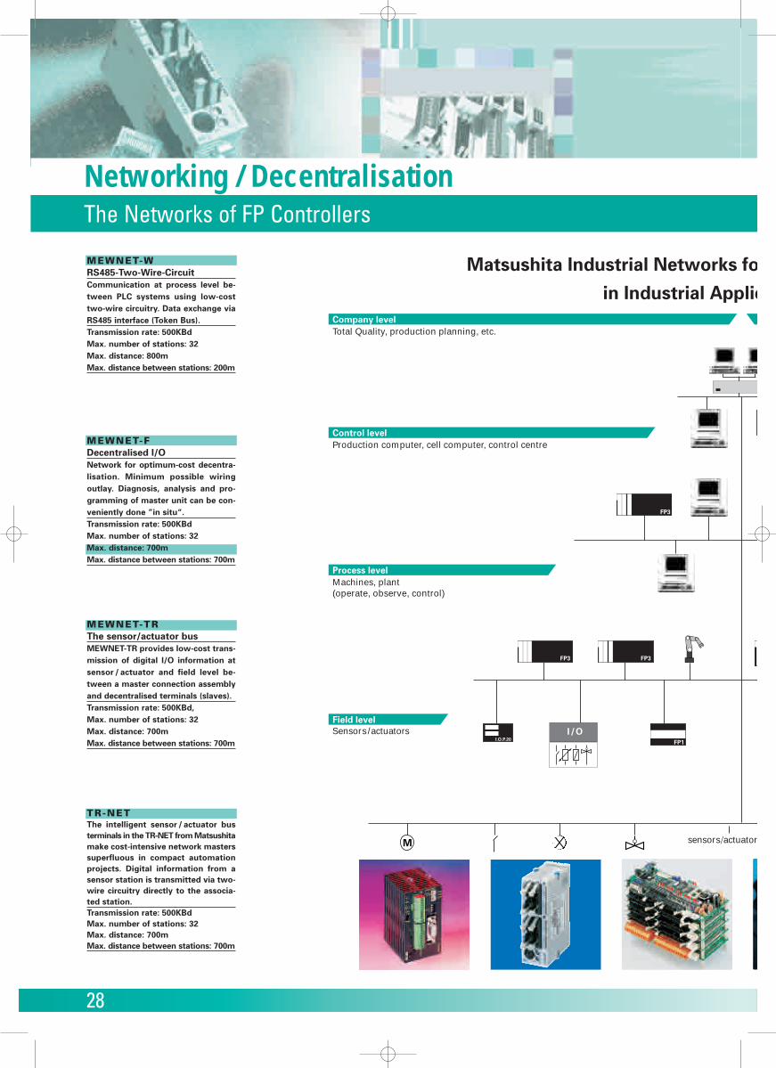
MEWNET-W RS485-Two-Wire-CircuitCommunication at process level be-tween PLC systems using low-costtwo-wire circuitry. Data exchange viaRS485 interface (Token Bus). Transmission rate: 500KBdMax. number of stations: 32Max. distance: 800mMax. distance between stations: 200m
MEWNET-F Decentralised I/ONetwork for optimum-cost decentra-lisation. Minimum possible wiringoutlay. Diagnosis, analysis and pro-gramming of master unit can be con-veniently done ”in situ“. Transmission rate: 500KBdMax. number of stations: 32Max. distance: 700mMax. distance between stations: 700m
MEWNET-TR The sensor/actuator busMEWNET-TR provides low-cost trans-mission of digital I/O information atsensor / actuator and field level be-tween a master connection assemblyand decentralised terminals (slaves).Transmission rate: 500KBd,Max. number of stations: 32Max. distance: 700mMax. distance between stations: 700m
TR-NET The intelligent sensor / actuator busterminals in the TR-NET from Matsushitamake cost-intensive network masterssuperfluous in compact automationprojects. Digital information from asensor station is transmitted via two-wire circuitry directly to the associa-ted station.Transmission rate: 500KBdMax. number of stations: 32Max. distance: 700mMax. distance between stations: 700m
Field level
Process level
Control level
Company levelTotal Quality, production planning, etc.
Production computer, cell computer, control centre
Machines, plant(operate, observe, control)
Sensors/actuators
sensors/actuator
FP3
FP1I.O.P.20
FP3 FP3
I /O
M
Matsushita Industrial Networks fo
in Industrial Applic
29
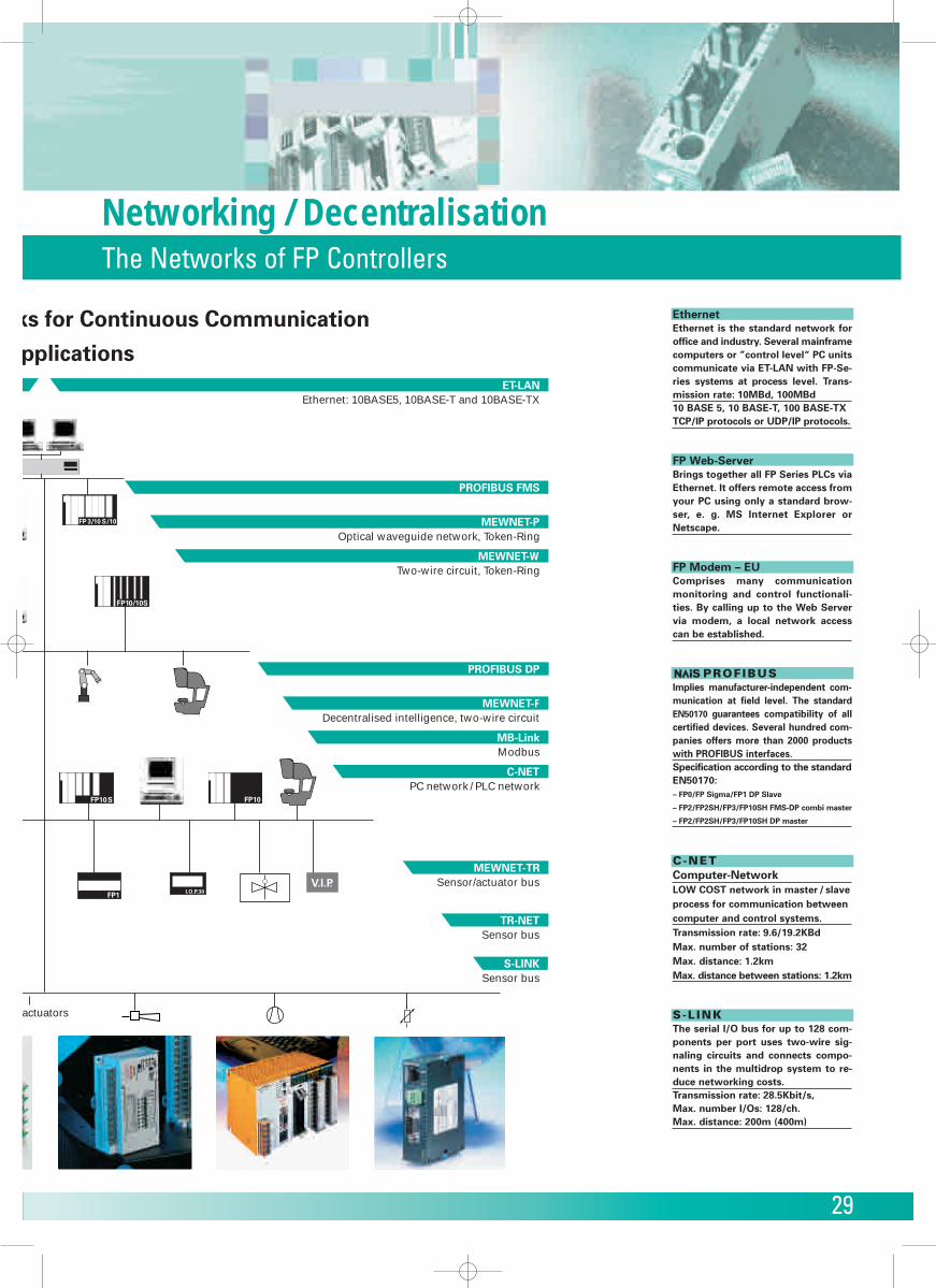
EthernetEthernet is the standard network foroffice and industry. Several mainframecomputers or ”control level“ PC unitscommunicate via ET-LAN with FP-Se-ries systems at process level. Trans-mission rate: 10MBd, 100MBd10 BASE 5, 10 BASE-T, 100 BASE-TXTCP/IP protocols or UDP/IP protocols.
FP Web-ServerBrings together all FP Series PLCs viaEthernet. It offers remote access fromyour PC using only a standard brow-ser, e. g. MS Internet Explorer orNetscape.
FP Modem – EUComprises many communicationmonitoring and control functionali-ties. By calling up to the Web Servervia modem, a local network accesscan be established.
PROFIBUS Implies manufacturer-independent com-munication at field level. The standardEN50170 guarantees compatibility of allcertified devices. Several hundred com-panies offers more than 2000 productswith PROFIBUS interfaces.Specification according to the standardEN50170:– FP0/FP Sigma/FP1 DP Slave
– FP2/FP2SH/FP3/FP10SH FMS-DP combi master
– FP2/FP2SH/FP3/FP10SH DP master
C-NET Computer-NetworkLOW COST network in master / slaveprocess for communication betweencomputer and control systems.Transmission rate: 9.6/19.2KBdMax. number of stations: 32Max. distance: 1.2kmMax. distance between stations: 1.2km
S-LINK The serial I/O bus for up to 128 com-ponents per port uses two-wire sig-naling circuits and connects compo-nents in the multidrop system to re-duce networking costs.Transmission rate: 28.5Kbit/s,Max. number I/Os: 128/ch.Max. distance: 200m (400m)
Networking / DecentralisationThe Networks of FP Controllers
TR-NET
MEWNET-TR
C-NET
MB-Link
MEWNET-F
MEWNET-P
PROFIBUS FMS
MEWNET-W
ET-LAN Ethernet: 10BASE5, 10BASE-T and 10BASE-TX
Optical waveguide network, Token-Ring
Two-wire circuit, Token-Ring
Decentralised intelligence, two-wire circuit
Modbus
PC network / PLC network
Sensor/actuator bus
Sensor bus
actuators
FP 3/10 S/10
FP10/10S
FP10S FP10
FP1 I.O.P.30V.I.P.
PROFIBUS DP
S-LINKSensor bus
ks for Continuous Communication
pplications
30
FP Web-ServerInternet / Intranet
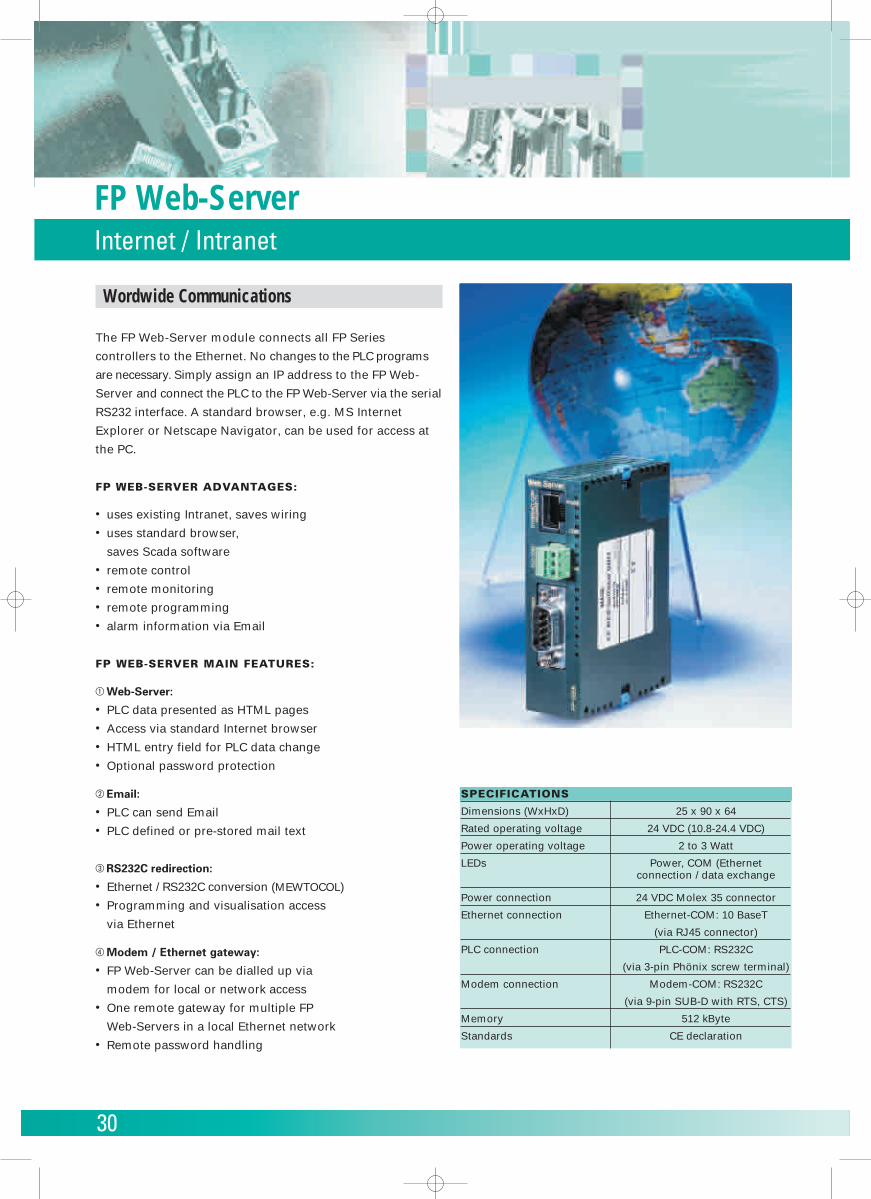
Wordwide Communications
The FP Web-Server module connects all FP Series
controllers to the Ethernet. No changes to the PLC programs
are necessary. Simply assign an IP address to the FP Web-
Server and connect the PLC to the FP Web-Server via the serial
RS232 interface. A standard browser, e.g. MS Internet
Explorer or Netscape Navigator, can be used for access at
the PC.
FP WEB-SERVER ADVANTAGES:
• uses existing Intranet, saves wiring • uses standard browser,
saves Scada software • remote control • remote monitoring • remote programming • alarm information via Email
FP WEB-SERVER MAIN FEATURES:
� Web-Server:
• PLC data presented as HTML pages• Access via standard Internet browser• HTML entry field for PLC data change• Optional password protection
� Email:
• PLC can send Email• PLC defined or pre-stored mail text
� RS232C redirection:
• Ethernet / RS232C conversion (MEWTOCOL)• Programming and visualisation access
via Ethernet
� Modem / Ethernet gateway:
• FP Web-Server can be dialled up via
modem for local or network access• One remote gateway for multiple FP
Web-Servers in a local Ethernet network • Remote password handling
SPECIFICATIONS
Dimensions (WxHxD) 25 x 90 x 64
Rated operating voltage 24 VDC (10.8-24.4 VDC)
Power operating voltage 2 to 3 Watt
LEDs Power, COM (Ethernetconnection / data exchange
Power connection 24 VDC Molex 35 connector
Ethernet connection Ethernet-COM: 10 BaseT
(via RJ45 connector)
PLC connection PLC-COM: RS232C
(via 3-pin Phönix screw terminal)
Modem connection Modem-COM: RS232C
(via 9-pin SUB-D with RTS, CTS)
Memory 512 kByte
Standards CE declaration
31
FP Modem-EUTelecontrol
Example: Combination of LAN and Dial-up Gateway
Standard specifications:
� Dial-up mode: European approval CTR21 includingpulse dial option.
� Leased line mode: European approval CTR 15, max.distance 20 km.
� Multipoint mode: Intelligent multidrop data transfer.
� Fax mode: Fax group 3 supported (command class 2)
� Test mode: V.54 analog and digital Test loop.
� Password protection and call back function.
Interface specifications:
� Transmission rate: up to 57600 bits/s
� Transmission standards: V.32bis, V.32, V22bis, V.22,V.23, V.21, V.17, V.27ter, V.29
� Error correction: V.42, V.42bis, LAPM, MNP4, MNP5,MNP10
� Data compression: MNP5, V.42bis
� AT instruction set (Hayes compatible).
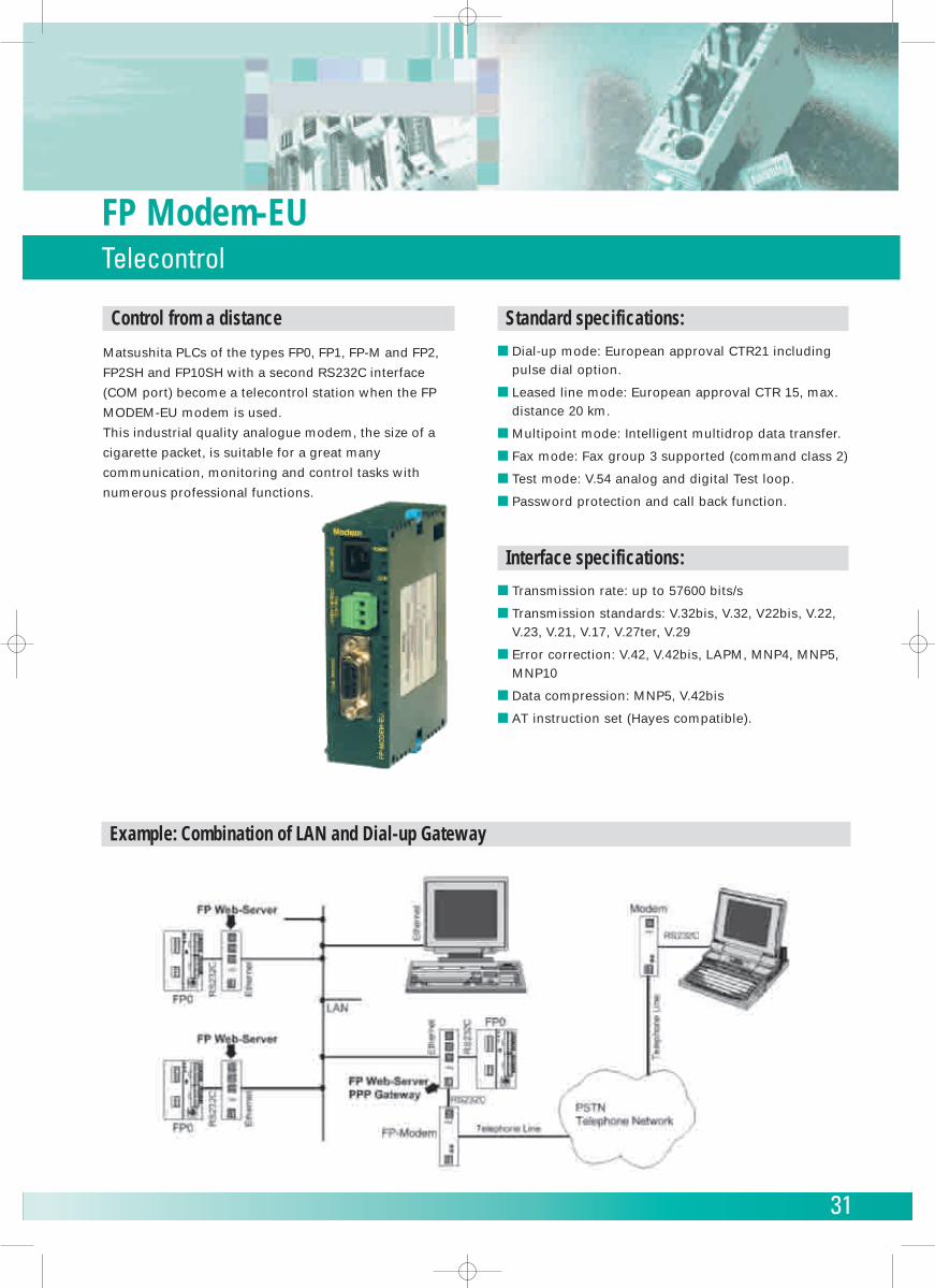
Control from a distance
Matsushita PLCs of the types FP0, FP1, FP-M and FP2,
FP2SH and FP10SH with a second RS232C interface
(COM port) become a telecontrol station when the FP
MODEM-EU modem is used.
This industrial quality analogue modem, the size of a
cigarette packet, is suitable for a great many
communication, monitoring and control tasks with
numerous professional functions.
32
Control FPWIN ProProgramming software
Control FPWIN programming tools works with any FP series programmable controller under Windows environment.
control FPWIN Pro
is the Matsushita programming software according to the international standard IEC 61131-3 (for Windows 95/98, NT or
2000). NAIS Control FPWIN Pro works with any FP series programmable controller. Also, since the tool port is an RS232C,
connection to a PC is easy – it only requires a single cable. No converter or adapter is required.
Programm upload of former Matsushita programming software is available. (NPST-GR, FP-Soft, FPWIN-GR).
The most important highlights at a glance:
• Reuse of ready made functions and function blocks saves time for programming and debugging
• 5 programming languages (instruction list, ladder diagram, function block diagram,
sequential function chart, structured text)
• Convenient comment application in 6 languages (English, German, French, Italien, Spanish, Japanese)
• 2 standard libraries (IEC-standard library, Matsushita library)
• Fewer errors through defined data types and encapsulation
• Well-structured through programme organisation units, task- and projectmanagement
• Online monitoring and diagnostic
• Ethernet and Modem communication for remote-programming, -service,
and -diagnostic
• Password protection with different levels
• Many additional application libraries available
• IEC 61131-3 protects your investments for the future
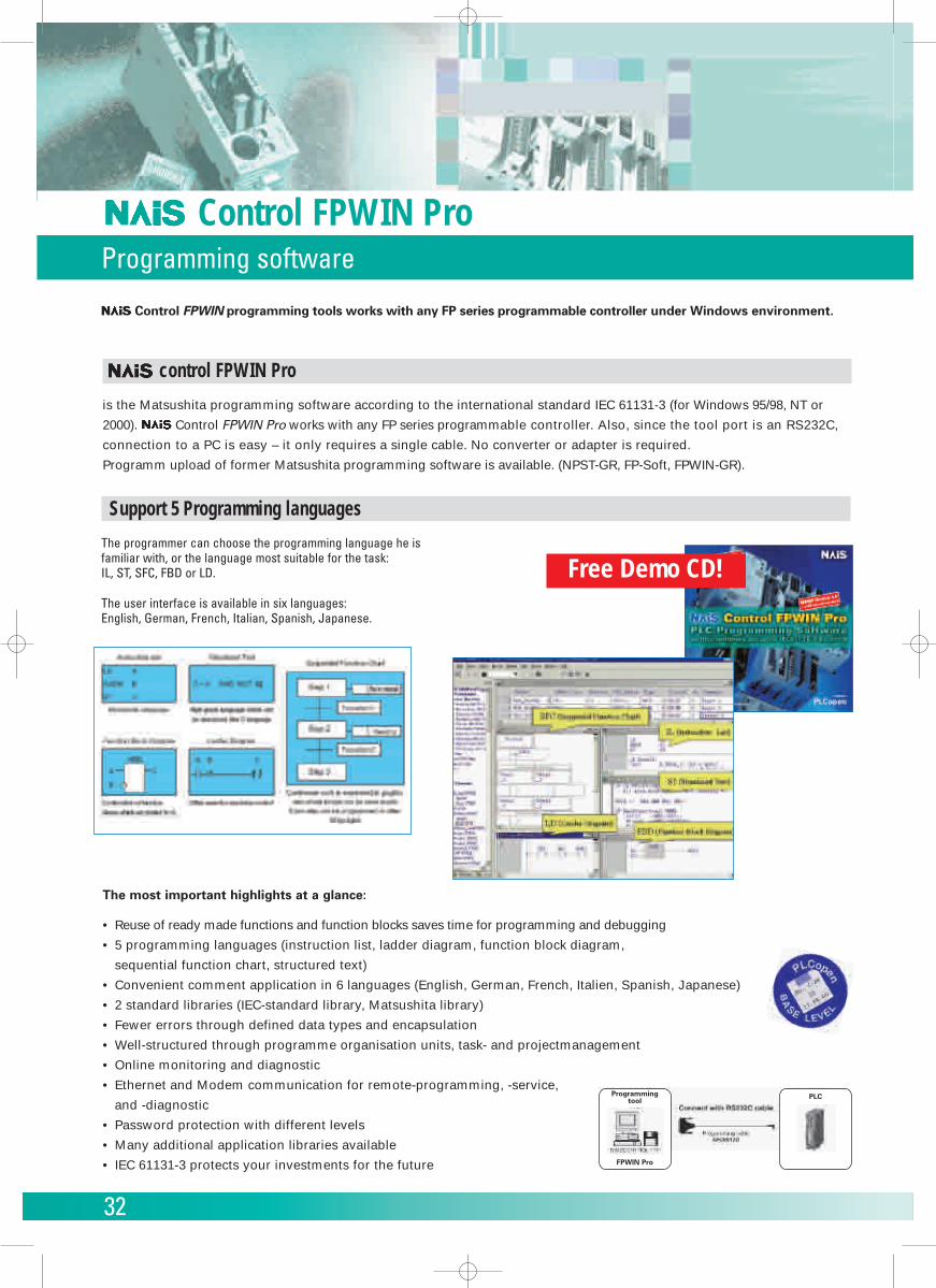
Support 5 Programming languages
Free Demo CD!The programmer can choose the programming language he isfamiliar with, or the language most suitable for the task:IL, ST, SFC, FBD or LD.
The user interface is available in six languages:English, German, French, Italian, Spanish, Japanese.
Programmingtool
FPWIN Pro
PLC
33
Control FPWIN GRProgramming software
Features
FP Series programming software for Windows.
1.To facilitate operation on site, a mouse is
not required for input, search, write,
monitor and timer edit operations.
Everything can be accomplished with a
keyboard, alone.
2.Standard Windows operations, such as
copy and paste, are included.
3.Supports all FP series machines. Soft-
ware created with NPST-GR Ver. 3 or
4 can also be used.
4. Inherits convenient functions developed
for NPST-GR.
Menu
Compatibility between the DOS version NPST-GR and the FPWIN-GR
• Files created with the NPST-GR Ver. 4 or Ver. 3 can be loaded (including I/O comments, remarks and block comments).• Programmes created with Microsoft Windows software can be read by NPST-GR using the export function. Howe-ver, comments cannot be read by NPST-GR using this method.• When programmes and comments created with the FPWIN GR are downloaded to the PLC, comments cannot be loadedwith the NPST-GR, but programmes can be loaded.• There are no merge registration or loading functions. Instead, the “Copy and Paste function” in Windows should be used.• Verifications cannot be carried out targeting files. The files to be verified must first be loaded, and then verified.• There are no multi-point monitoring or multi-data monitoring functions.• You cannot display the network status on the online status display.
Usage environment
OS Windows 95/98/NT(ver. 4.0 or later)
Required hard disc capacity at least 30MBRecommended CPU Pentium 100MHz
or higherRecommendedinstalled memory 32MB or moreRecommendedscreen resolution 800 x 600 or higherRecommended High colordisplay colors (16bit or higher)
Applicable PLC types
All products on the market as of June 2000
are supported. All FP series types are suppor-
ted: FP0, FP1, FP2, FP2SH, FP3, FP10SH, FP-M
FP-Sigma
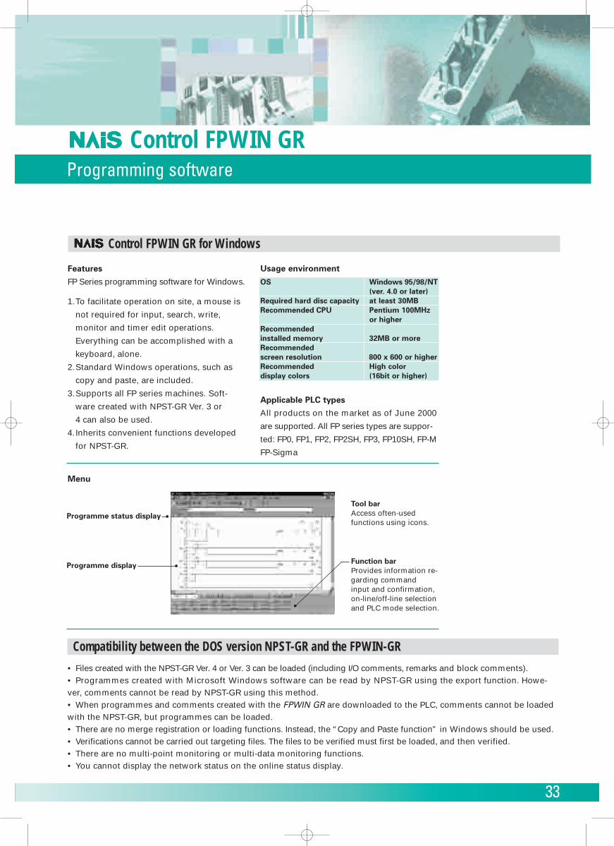
Programme status display
Programme display
Tool barAccess often-usedfunctions using icons.
Function barProvides information re-garding command input and confirmation,on-line/off-line selectionand PLC mode selection.
Control FPWIN GR for Windows
34
EASY Setting Data on EXCEL
By setting the necessary items at the (Cell
Settings) dialog box, it is possible to READ
or WRITE the PLC data.
Data Storage / Printing…
… in automatic operation.
Register the data at periodical or non-periodi-
cal, in accordance to the relay or PCWAY
event turning to ON.
Save the data with the TEXT format. The file
format can be registered flexibily. Also, the
data can be written-in and processed at a dif-
ferent application, other than the Excel one.
Versatility
• (Automatic Macro Startup): Starts the
registered macro (registered by the User)
by the event turning to ON.
• (Sound File): The sound will be out-putted
by the PLC relay and event turning ON.
Remote Data Management…
… via modem.
(Modem Support): Connects with the PLCs locat-
ed in distant regions with the public phone line.
Interactive Data Exchange
… (PLC –� PC).
Possible to download the displayed data to
the PLC.
EASY OPERATIONAL ENVIRONMENT
For those who do not want to use the ma-
cro programme...
• (Character Change): Changes the display
character/colour by the ON/OFF of the relay.
• (Operation Formula): perform an opera-
tion during the displaying and the opera-
tion of the register.
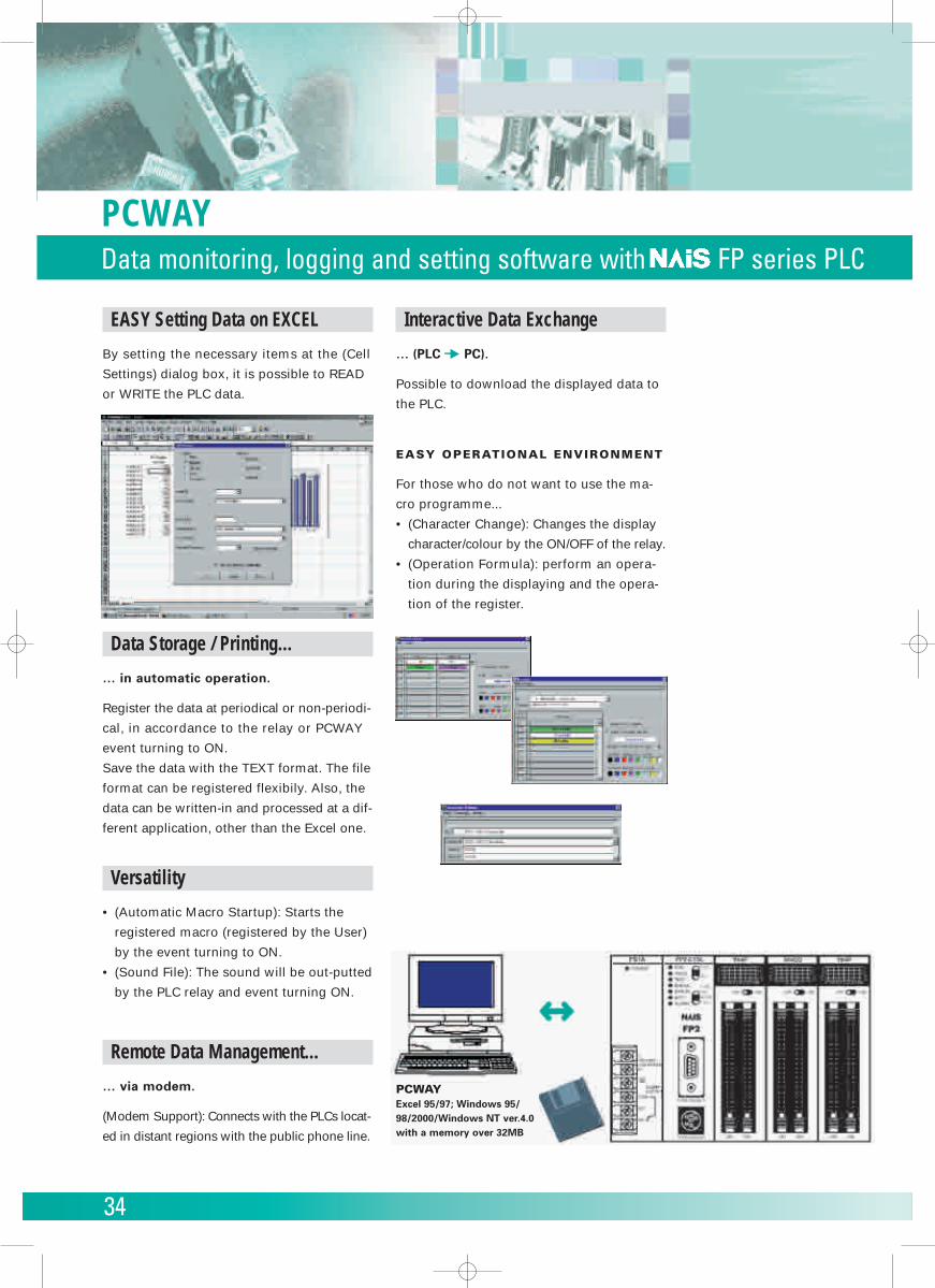
PCWAYExcel 95/97; Windows 95/98/2000/Windows NT ver.4.0with a memory over 32MB
PCWAYData monitoring, logging and setting software with FP series PLC
35
Connects your Visual Basic application to Matsushita PLCs
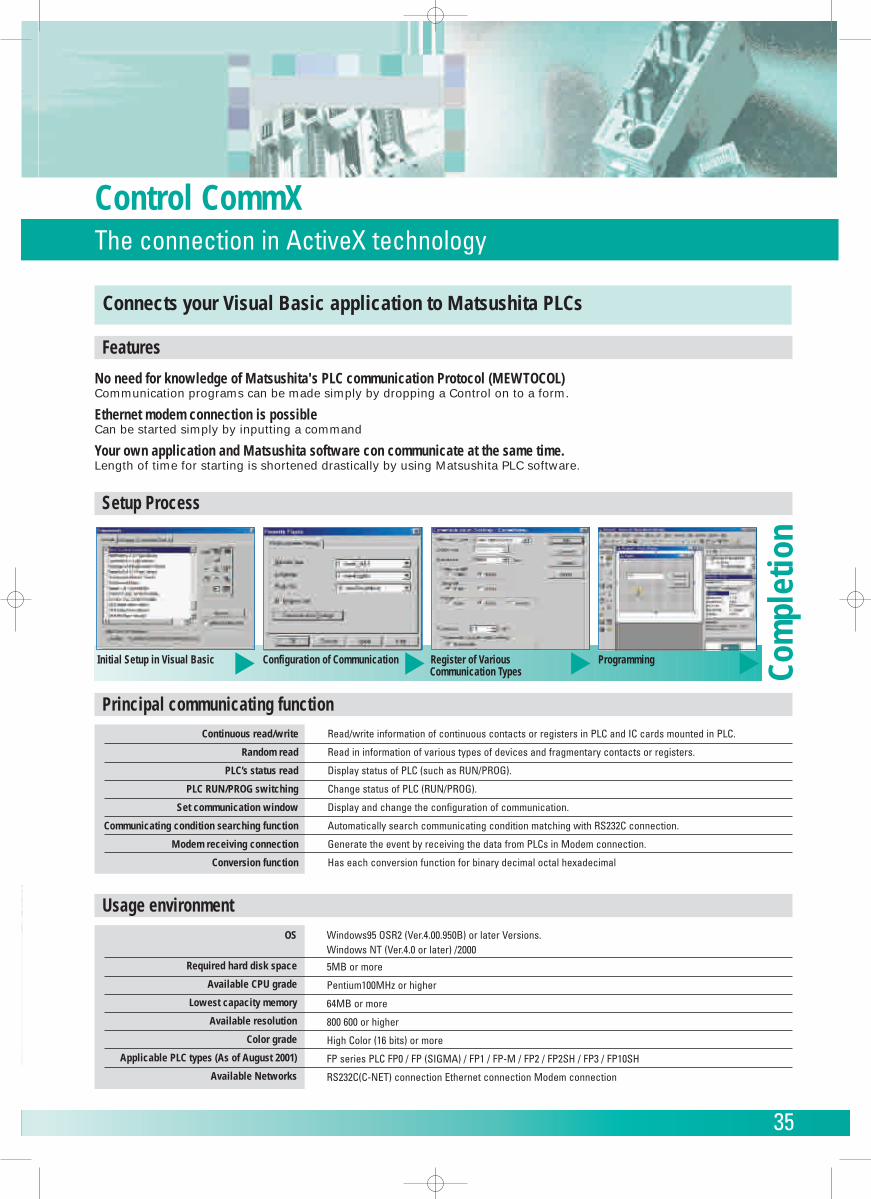
Initial Setup in Visual Basic Configuration of Communication Register of Various Programming
OS
Required hard disk space
Available CPU grade
Lowest capacity memory
Available resolution
Color grade
Applicable PLC types (As of August 2001)
Available Networks
Windows95 OSR2 (Ver.4.00.950B) or later Versions.Windows NT (Ver.4.0 or later) /2000
5MB or more
Pentium100MHz or higher
64MB or more
800 600 or higher
High Color (16 bits) or more
FP series PLC FP0 / FP (SIGMA) / FP1 / FP-M / FP2 / FP2SH / FP3 / FP10SH
RS232C(C-NET) connection Ethernet connection Modem connection
Continuous read/write
Random read
PLC’s status read
PLC RUN/PROG switching
Set communication window
Communicating condition searching function
Modem receiving connection
Conversion function
Read/write information of continuous contacts or registers in PLC and IC cards mounted in PLC.
Read in information of various types of devices and fragmentary contacts or registers.
Display status of PLC (such as RUN/PROG).
Change status of PLC (RUN/PROG).
Display and change the configuration of communication.
Automatically search communicating condition matching with RS232C connection.
Generate the event by receiving the data from PLCs in Modem connection.
Has each conversion function for binary decimal octal hexadecimal
Features
No need for knowledge of Matsushita's PLC communication Protocol (MEWTOCOL)Communication programs can be made simply by dropping a Control on to a form.
Ethernet modem connection is possibleCan be started simply by inputting a command
Your own application and Matsushita software con communicate at the same time.Length of time for starting is shortened drastically by using Matsushita PLC software.
Setup Process
Usage environment
Principal communicating function
Communication Types
� � � �
Com
plet
ion
Control CommXThe connection in ActiveX technology
36
Human Machine interfacesG-Series
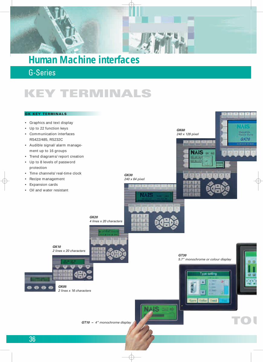
GK60240 x 128 pixel
GK204 lines x 20 characters
GK30240 x 64 pixel
GK102 lines x 20 characters
GT305.7” monochrome or colour display
GT10 – 4” monochrome display
GK052 lines x 16 characters
GK KEY TERMINALS
• Graphics and text display
• Up to 22 function keys
• Communication interfaces
RS422/485, RS232C
• Audible signal/ alarm manage-
ment up to 16 groups
• Trend diagrams/ report creation
• Up to 8 levels of password
protection
• Time channels/ real-time clock
• Recipe management
• Expansion cards
• Oil and water resistant
KEY TERMINALS
TOU
37
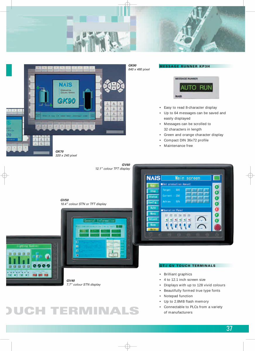
GK90640 x 480 pixel
GK70320 x 240 pixel
GV407.7” colour STN display
GV5010.4” colour STN or TFT display
GV6012.1” colour TFT display
GT- / GV TOUCH TERMINALS
• Brilliant graphics
• 4 to 12.1 inch screen size
• Displays with up to 128 vivid colours
• Beautifully formed true type fonts
• Notepad function
• Up to 2.8MB flash memory
• Connectable to PLCs from a variety
of manufacturers
MESSAGE RUNNER KP3H
• Easy to read 8-character display
• Up to 64 messages can be saved and
easily displayed
• Messages can be scrolled to
32 characters in length
• Green and orange character display
• Compact DIN 36x72 profile
• Maintenance free
OUCH TERMINALS
38
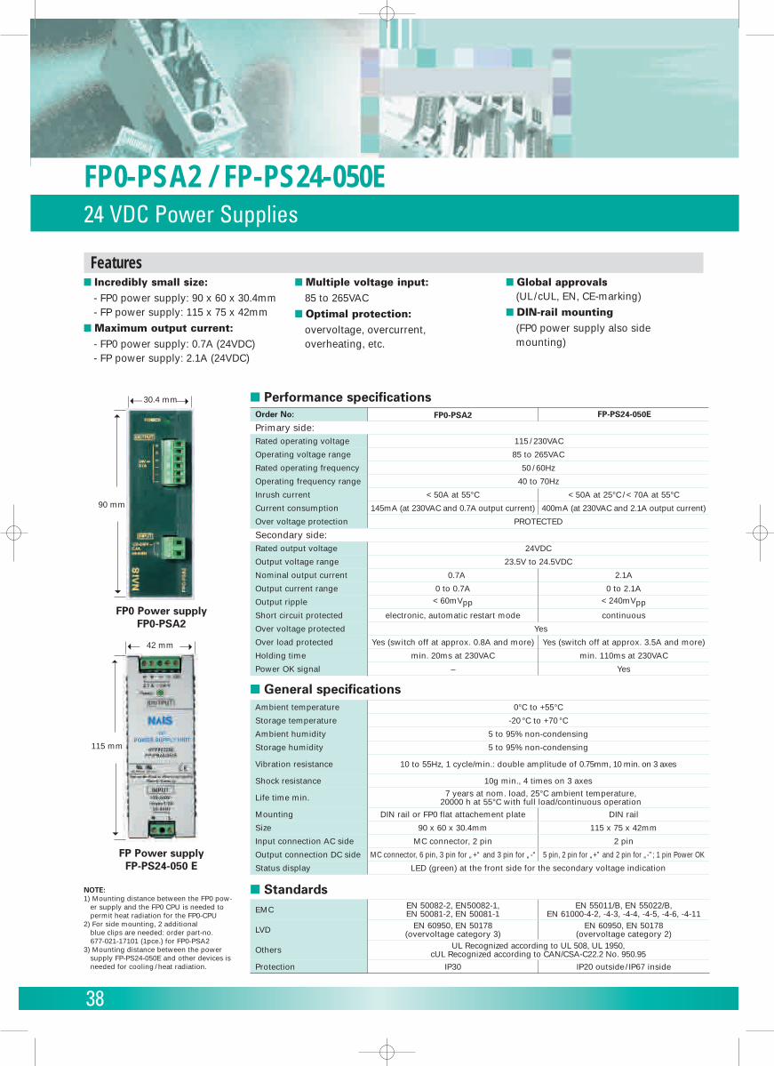
FP0-PSA2 / FP-PS24-050E24 VDC Power Supplies
� Incredibly small size:
- FP0 power supply: 90 x 60 x 30.4mm- FP power supply: 115 x 75 x 42mm
� Maximum output current:
- FP0 power supply: 0.7A (24VDC)- FP power supply: 2.1A (24VDC)
� Multiple voltage input:
85 to 265VAC� Optimal protection:
overvoltage, overcurrent, overheating, etc.
� Global approvals (UL/cUL, EN, CE-marking)
� DIN-rail mounting
(FP0 power supply also sidemounting)
Primary side:Rated operating voltage
Operating voltage range
Rated operating frequency
Operating frequency range
Inrush current
Current consumption
Over voltage protection
Secondary side:Rated output voltage
Output voltage range
Nominal output current
Output current range
Output ripple
Short circuit protected
Over voltage protected
Over load protected
Holding time
115 / 230VAC
85 to 265VAC
50 / 60Hz
40 to 70Hz
< 50A at 55°C < 50A at 25°C / < 70A at 55°C
145mA (at 230VAC and 0.7A output current)
PROTECTED
24VDC
23.5V to 24.5VDC
0.7A
0 to 0.7A< 60mVpp
electronic, automatic restart mode
Yes
Yes (switch off at approx. 0.8A and more)
min. 20ms at 230VAC
Order No: FP0-PSA2 FP-PS24-050E
400mA (at 230VAC and 2.1A output current)
2.1A
0 to 2.1A< 240mVpp
continuous
Yes (switch off at approx. 3.5A and more)
min. 110ms at 230VAC
Power OK signal – Yes
� Performance specifications
Ambient temperature
Storage temperature
Ambient humidity
Storage humidity
Vibration resistance
Shock resistance
Life time min.
Mounting
Size
Input connection AC side
Output connection DC side
Status display
0°C to +55°C
-20 °C to +70 °C
5 to 95% non-condensing
5 to 95% non-condensing
10 to 55Hz, 1 cycle/min.: double amplitude of 0.75mm, 10 min. on 3 axes
10g min., 4 times on 3 axes7 years at nom. load, 25°C ambient temperature,
20000 h at 55°C with full load/continuous operationDIN rail or FP0 flat attachement plate
90 x 60 x 30.4mm
MC connector, 2 pin
MC connector, 6 pin, 3 pin for „+“ and 3 pin for „-“
DIN rail
115 x 75 x 42mm
2 pin
5 pin, 2 pin for „+” and 2 pin for „-”; 1 pin Power OK
LED (green) at the front side for the secondary voltage indication
� General specifications
EMC
LVD
Others
Protection
EN 50082-2, EN50082-1, EN 50081-2, EN 50081-1
EN 55011/B, EN 55022/B, EN 61000-4-2, -4-3, -4-4, -4-5, -4-6, -4-11
EN 60950, EN 50178 (overvoltage category 3)
EN 60950, EN 50178 (overvoltage category 2)
UL Recognized according to UL 508, UL 1950, cUL Recognized according to CAN/CSA-C22.2 No. 950.95
IP30 IP20 outside/ IP67 inside
� StandardsNOTE: 1) Mounting distance between the FP0 pow-
er supply and the FP0 CPU is needed topermit heat radiation for the FP0-CPU
2) For side mounting, 2 additional blue clips are needed: order part-no. 677-021-17101 (1pce.) for FP0-PSA2
3) Mounting distance between the powersupply FP-PS24-050E and other devices isneeded for cooling / heat radiation.
FP0 Power supplyFP0-PSA2
FP Power supplyFP-PS24-050 E
➝
➝
30.4 mm
➝
90 mm
➝➝
➝
42 mm
➝
115 mm
➝
Features

Copyright © 2002 • Printed in Germany4104 eu en 08/02
Please contact our Global Sales Companies in:
Europe
� Europe Matsushita Electric Works (Europe) AG Rudolf-Diesel-Ring 2, D-83607 Holzkirchen, Tel. (08024) 648-0, Fax (08024) 648-111, www.mew-europe.com� Austria Matsushita Electric Works Austria GmbH Josef Madersperger Straße 2, A-2362 Biedermannsdorf, Tel. (0 22 36) 2 68 46, Fax (0 22 36) 4 61 33, www.matsushita.at� Benelux Matsushita Electric Works Benelux B.V. De Rijn 4, (Postbus 211), 5684 PJ Best, (5680 AE Best), Netherlands, Tel. (0499) 372727, Fax (0499) 372185, www.matsushita.nl, www.matsushita.be� France Matsushita Electric Works France S.A.R.L. B.P. 44, F-91371 Verrières le Buisson CEDEX, Tél. 01 60135757, Fax 01 60135758, www.matsushita-france.fr� Germany Matsushita Electric Works Deutschland GmbH Rudolf-Diesel-Ring 2, D-83607 Holzkirchen, Tel. (08024) 648-0, Fax (08024) 648-555, www.matsushita.de� Ireland Matsushita Electric Works UK Ltd. Irish Branch Office, Waverley, Old Naas Road, Bluebell, Dublin 12, Republic of Ireland, Tel: (01) 4600969, Fax: (01) 4601131, www.matsushita.ie� Italy Matsushita Electric Works Italia s.r.l. Via del Commercio 3-5 (Z.I. Ferlina), I-37012 Bussolengo (VR), Tel. (045) 6752711, Fax (045) 6700444, http://www.matsushita.it� Portugal Matsushita Electric Works España S.A. Portuguese Branch Office, Avda 25 de Abril, Edificio Alvorada 5-ºE, 2750-512 Cascais, Portugal, Tel. (21) 4828266, Fax (21) 4827421� Scandinavia Matsushita Electric Works Scandinavia AB Sjöängsvägen 10, 19272 Sollentuna, Sweden, Tel. (08) 59476680, Fax (08) 59476690, www.matsushita.se� Spain Matsushita Electric Works España S.A. Parque Empresarial Barajas, San Severo 20, E-28042 Madrid, Tel. (91) 3293875, Fax (91) 3292976, www.matsushita.es� Switzerland Matsushita Electric Works Schweiz AG Grundstrasse 8, CH-6343 Rotkreuz, Tel. (041) 7997050, Fax (041) 7997055, www.matsushita.ch� United Kingdom Matsushita Electric Works UK Ltd. Sunrise Parkway, Linford Wood East, Milton Keynes, MK14 6LF, England, Tel. (01908) 231555, Fax (01908) 231599, www.matsushita.co.uk
North & South America
� USA Aromat Corporation Head Office USA 629 Central Avenue, New Providence, N.J. 07974, Tel. 1-908-464-3550, Fax 1-908-464-8513, www.aromat.com
Asia
� China Matsushita Electric Works Ltd. China Office 2013, Beijing Fortune, Building No. 5, Dong San Huan Bei Lu, Chaoyang District, Beijing, Tel. 86-10-6590-8646, Fax 86-10-6590-8647� Hong Kong Matsushita Electric Works Ltd. Hong Kong Rm1601, 16/F, Tower 2, The Gateway, 25 Canton Road, Tsimshatsui, Kowloon, Hong Kong, Tel. (852) 2956-3118, Fax (852) 2956-0398� Japan Matsushita Electric Works Ltd. 1048 Kadoma, Kadoma-shi, Osaka 571-8686, Japan, Tel. 06-6908-1050, Fax 06-6908-5781, www.mew.co.jp/e-acg/� Singapore Matsushita Electric Works 101 Thomson Road, #25-03/05, United Square, Singapore 307591, Tel. (65) 6255-5473, Fax (65) 6253-5689
(Asia Pacific) Pte. Ltd.
Matsushita Electric Works
North America
AromatCorporation
Asia Pacific
MatsushitaElectric Works
China
MatsushitaElectric Works
Japan
MatsushitaElectric Works, Ltd.AutomationControls Group
Europe
MatsushitaElectric Works
Global Network Services