matthews arcade machine -...
TRANSCRIPT
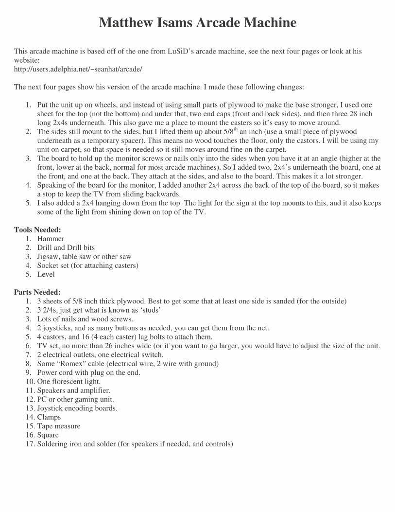
Matthew Isams Arcade Machine
This arcade machine is based off of the one from LuSiD’s arcade machine, see the next four pages or look at his website: http://users.adelphia.net/~seanhat/arcade/ The next four pages show his version of the arcade machine. I made these following changes:
1. Put the unit up on wheels, and instead of using small parts of plywood to make the base stronger, I used one sheet for the top (not the bottom) and under that, two end caps (front and back sides), and then three 28 inch long 2x4s underneath. This also gave me a place to mount the casters so it’s easy to move around.
2. The sides still mount to the sides, but I lifted them up about 5/8th an inch (use a small piece of plywood underneath as a temporary spacer). This means no wood touches the floor, only the castors. I will be using my unit on carpet, so that space is needed so it still moves around fine on the carpet.
3. The board to hold up the monitor screws or nails only into the sides when you have it at an angle (higher at the front, lower at the back, normal for most arcade machines). So I added two, 2x4’s underneath the board, one at the front, and one at the back. They attach at the sides, and also to the board. This makes it a lot stronger.
4. Speaking of the board for the monitor, I added another 2x4 across the back of the top of the board, so it makes a stop to keep the TV from sliding backwards.
5. I also added a 2x4 hanging down from the top. The light for the sign at the top mounts to this, and it also keeps some of the light from shining down on top of the TV.
Tools Needed:
1. Hammer 2. Drill and Drill bits 3. Jigsaw, table saw or other saw 4. Socket set (for attaching casters) 5. Level
Parts Needed:
1. 3 sheets of 5/8 inch thick plywood. Best to get some that at least one side is sanded (for the outside) 2. 3 2/4s, just get what is known as ‘studs’ 3. Lots of nails and wood screws. 4. 2 joysticks, and as many buttons as needed, you can get them from the net. 5. 4 castors, and 16 (4 each caster) lag bolts to attach them. 6. TV set, no more than 26 inches wide (or if you want to go larger, you would have to adjust the size of the unit. 7. 2 electrical outlets, one electrical switch. 8. Some “Romex” cable (electrical wire, 2 wire with ground) 9. Power cord with plug on the end. 10. One florescent light. 11. Speakers and amplifier. 12. PC or other gaming unit. 13. Joystick encoding boards. 14. Clamps 15. Tape measure 16. Square 17. Soldering iron and solder (for speakers if needed, and controls)
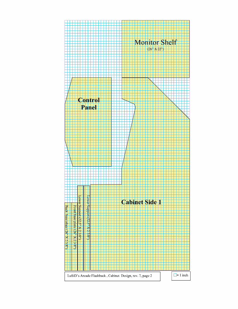
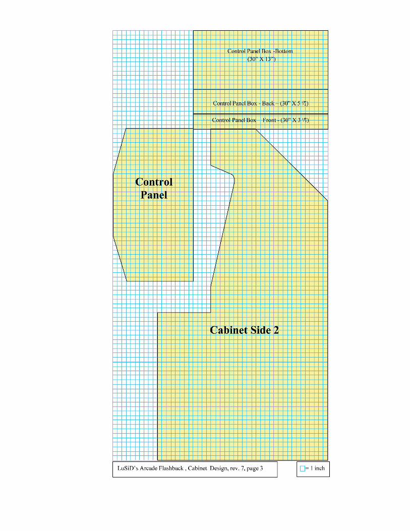

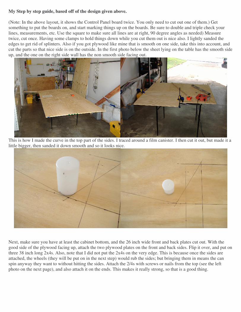
My Step by step guide, based off of the design given above. (Note: In the above layout, it shows the Control Panel board twice. You only need to cut out one of them.) Get something to put the boards on, and start marking things up on the boards. Be sure to double and triple check your lines, measurements, etc. Use the square to make sure all lines are at right, 90 degree angles as needed) Measure twice, cut once. Having some clamps to hold things down while you cut them out is nice also. I lightly sanded the edges to get rid of splinters. Also if you got plywood like mine that is smooth on one side, take this into account, and cut the parts so that nice side is on the outside. In the first photo below the sheet lying on the table has the smooth side up, and the one on the right side wall has the non smooth side facing out.
This is how I made the curve in the top part of the sides. I traced around a film canister. I then cut it out, but made it a little bigger, then sanded it down smooth and so it looks nice.
Next, make sure you have at least the cabinet bottom, and the 26 inch wide front and back plates cut out. With the good side of the plywood facing up, attach the two plywood plates on the front and back sides. Flip it over, and put on three 38 inch long 2x4s. Also, note that I did not put the 2x4s on the very edge. This is because once the sides are attached, the wheels (they will be put on in the next step) would rub the sides; but bringing them in means the can spin anyway they want to without hitting the sides. Attach the 2/4s with screws or nails from the top (see the left photo on the next page), and also attach it on the ends. This makes it really strong, so that is a good thing.

Next, attach the casters. I put in some scrap plywood under them, to lift the unit up a little more, and also keep the long bolts from going all the way through the 2x4 and the plywood. See photos below. Once you get all this done, put it on the ground, and have some fun going down your driveway, or have someone push you around. If it doesn’t roll, you have a problem; correct it now before going on.
Next, attach the sides. Be sure to screw into the bottom cabinet board, and also into the front and back base plates. For more strength, I added some nails though the side panels into the 2x4s that the casters are on. Also I attached the front panel, also known as the coin door. If you are going to put in a real coin machine here, it might be good to put this panel on some hinges and put a lock on it also. At this point, I did not put on the bottom back panel, because I have more wiring to do.

Next is the speaker panel. As of this point, I just added in some basic speakers, with plans about adding in some good speakers in the future. I measured 5 inches in from the sides, and three inches in from the front. This was my center point to drill with a “door knob” drill bit. Once again, I sanded the insides of the holes a little to remove the rough edges.
Adding in the speakers. What I did here is take apart a pair of computer speakers. They were a basic set, and one speaker had the transformer (seen in the right photo at the top right side). It also had a mini amplifier, seen in the right photo just above the speaker. I plugged in a CD player to try it out. As you can see, the green light is on so that means it works. The amplifier was mounted on standoffs, but depending on what you have you may not need them.

Next I installed the top most board, and also the back slanted part. Then added in a 2x4 hanging down, and mounted a florescent light to it. I put in the speaker panel, and made sure all the wires hung down correctly. Once again I tested the sound, and the light. Now I have some music to work to.
Next, I added in an electrical box. Yeah, it’s not a real one, but a wood one. I made it where it sits just a little higher than the bottom back board. On the back of the box is a switch that turns off both outlets. Plugged into the outlets so far are the speakers and the light. I have more outlets there for the TV, computer and anything else I plug in, such as a real Atari. I also attached the electrical feed line to the side, and then down to the bottom. I put a small notch in the bottom back board for it to stick out from. In the second photo (it’s on its side) you can see the unit from the front. I put in the board for the monitor, and as you can see, I put in two support boards (2x4s) to help support it. What you can’t see is another 2x4 on top of this monitor shelf. It is near the back, and there to keep the TV from sliding backwards. It is adjustable depending on how deep the tv you put in happens to be.
So far I spent 11 hours on this. You might take longer, or less, but I took my time to make sure it comes out 100% right. I have spent two days on it, three hours the first day, and eight the next day.
Painting Make sure all edges are sanded down. Wipe down all areas of the unit to remove stuck on dust. Its good to do all areas, inside and out. Some people, instead of painting, use contact paper to finish the outside. This should be easy to do, just cut it to fit and stick it on, making sure not to stretch it too much, and keep the bubbles out. Painting is easy, most people can paint. I wont go into much detail, just be careful not to glob the paint on, I have seen so many people get so much paint on the brush, and then glob it on, making a mess, and the paint runs down and makes a nice glob all over it. Take your time, and do two coats of paint as needed.
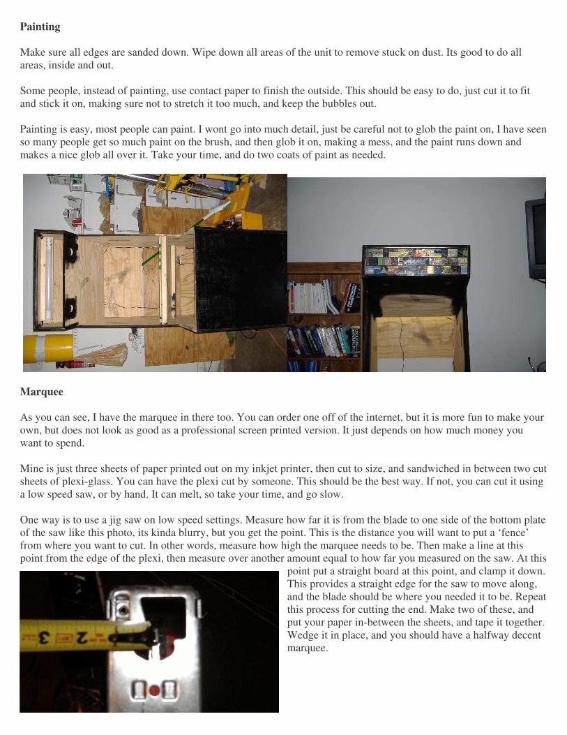
Marquee As you can see, I have the marquee in there too. You can order one off of the internet, but it is more fun to make your own, but does not look as good as a professional screen printed version. It just depends on how much money you want to spend. Mine is just three sheets of paper printed out on my inkjet printer, then cut to size, and sandwiched in between two cut sheets of plexi-glass. You can have the plexi cut by someone. This should be the best way. If not, you can cut it using a low speed saw, or by hand. It can melt, so take your time, and go slow. One way is to use a jig saw on low speed settings. Measure how far it is from the blade to one side of the bottom plate of the saw like this photo, its kinda blurry, but you get the point. This is the distance you will want to put a ‘fence’ from where you want to cut. In other words, measure how high the marquee needs to be. Then make a line at this point from the edge of the plexi, then measure over another amount equal to how far you measured on the saw. At this
point put a straight board at this point, and clamp it down. This provides a straight edge for the saw to move along, and the blade should be where you needed it to be. Repeat this process for cutting the end. Make two of these, and put your paper in-between the sheets, and tape it together. Wedge it in place, and you should have a halfway decent marquee.

Wiring and Buttons Now it gets fun! Time to break out the soldering iron, screwdrivers, and other tools. But first, design out your control panel, mark the spots on your control panel, and drill the holes. I used a 1 and 1/8 inch drill bit for all the buttons and joysticks. As for the design, you can draw it out, or use some of the software out on the Internet. Just do a Google search for it, its out there. I would include links to the sites, but I don’t have them as of the writing of this document, and plus websites change all the time. Be sure to leave some space between the buttons, as you need room underneath for the switch, wiring, etc.
Here is a simple layout, of one joystick, and four buttons. This suits most games, except for some of the major fighting games that uses six, or even eight buttons. I ended up drilling two more holes to get six buttons per player. I drilled this pattern of six buttons and one joystick twice, once on the left, and once on the right, for player one and two. Some people might want to make more for a third or even fourth player, but remember, there needs to be enough room for the players to stand or sit in front of the machine, and the screen needs to be big enough for more players. See below for a printable template for the joystick and up to six buttons.
Carry on drilling out for the other buttons, such as player 1,2,3 and 4 buttons, coin buttons, etc. Depending on the games you play, or the features you want to be able to use, you need more buttons. Keep in mind, stuff like “Service Mode” (F2 by default in MAME) is something you might not want everyone to get into, and chances are you don’t have to get into it every day. I put a hidden switch for this, I will discuss it later on. If you have kids that are going to use it, any and every button will get pressed! Trust me on this.

Here is my control panel as I am building it. You can put in the buttons where they belong, and tighten them down. For the time being, put on only the buttons, but not the switch itself. Take a look and see how yours looks. In the first few photos, I had not drilled all the holes all the way though. I also filled in some of the defects in the board with putty so its smooth, and then came back and painted over it. The photo on the bottom right shows the buttons I ordered from Happ Controls. http://www.happcontrols.com That’s where I also got the joysticks, I already installed them in the photos below.
Now the REALLY fun part. Wires!!! Now its time to explain something I did, you might choose to do something different. But there is good reason why I did this. First, I bought two “Stelladaptors”. These devices are available at http://www.atariage.com. I wired the first button, and the joysticks to each unit. The reasons why I did this is:
1. It uses a nine pin connector (well, only like six of the pins) for each joystick and one button. This it uses the same pinout as used on the Atari 2600, Commodore Vic-20/64/128. This means if I want to put one of these units in my arcade machine, I can just unplug the joystick from the Stelladaptor, and plug it into something else, and it will still work.
2. This separates the joysticks from the other buttons, and helps prevent “Ghosting” where you push three or more buttons at once (happens a lot when two people are playing) and you get the wrong keys, or it does not register them as being pressed.
3. The Stelladaptor is detected in windows as a normal joystick, and can be used with other games that might not accept remaping the keyboard.
4. They still take “8-way” joysticks, and that is what you should get, 8-way. 5. I can still unplug the joysticks, and attach a real set of Atari Paddle controllers to it.

Here is a photo I took of the Stelladaptor. It is the “standard” nine pin joystick connector on one end, and USB on the other. To start off, I took off the four switches on the bottom of the joystick, and one switch for the first button. One wire is common and then four more wires for up, down, left and right, and one more for the button. The pinout of this connector is:
On the female connection (the wire from the joysticks needs to be female, you can pick up these connectors from Radio Shack) the pin ‘1’ is on the top right, but on the male connection (on the Stelladaptor) has pin one on the top left. Also, for the female, the pin 9 is bottom left, and
on male, bottom right. You can also “steal” a cable off of an existing joystick of this type. If you do this, usually the color of the wires in the cable will be what is shown in the “Color” column below. Sometimes this is not the case, so look at your current
joystick that you took the wire off of, or use a meter to find out what wire goes where. Pin Color Use 1 White Up 2 Blue Down 3 Green Left 4 Brown Right 5 Not Used 6 Orange Button 7 Not Used 8 Black Ground 9 Not used Now use the Black wire, pin number 8, and run it to the one button and all four of the switches on the joystick. This will connect where the “Common” connection shows on the button hardware, in my case, it was the connection on the bottom of the button, not the ones on the side. You can solder the ground wire to the button, and then run a second wire to the ground on the first joystick switch, and then another wire to the next, and so on. I used a clip on “Heat Sink” to the connection to keep the heat from the soldering iron from messing up the switch. If you cant solder, or don’t want to, you can get a few of the .187inch crimp on connections that you crimp on the end of the wire, and it just slides on the connections of the switches. In some ways I found this to be better, as with rough game play (hey, those joysticks get abused bad!) the solder joints come loose. Also this method lets you make changes easily, and if you made a mistake during hooking it up, you can change it easily. The next part is easy, run each wire from the cable to the correct switch as shown in the chart above. Connect them to the “normally open” pin on the switch. One thing to keep in mind as for the joystick, the connections is different because you are underneath the control board, not on top. So move the joystick on top, and see what way it moves under it. Once you made it this far, double check your work. Now its time to test it out, hook up the joystick to the Stelladaptor, and to the computer with a USB cable. It should install itself, refer to the guide that came with the Stelladaptor if needed.

Here are some photos from my progress:
These first two show the joystick, and four buttons. I removed the four switches from the bottom of the joystick, and put the wires on them for the ground, or common connection in the right photo.
Above I went ahead of myself, and put in three more switches. All I did put one wire on the common connection of each switch, and one on the “normally open”. Even with the Common or ground wires being all connected together on the joystick and first button, DON’T connect the ground wires together, or to anything just yet. I will show this being used later on. Time to test it out. Open up the control panel in Windows, (start, settings, control panel), and you should see an icon for “Gaming Controllers” or something like that. Double click on it. You should get a page with the listings of the adaptor at the bottom. If you already did a second joystick, you might see two listed. Select one, and click on “Properties”. On this screen, there is a place to calibrate the joystick, do so, and follow the instructions. After that, select the “test” tab, and you can test the button, and moving the joystick. You can see this screen as shown here at left.

If you have not already done the second joystick, do so now. If the first one did not work, double-check your wires, connections and so on. In MAME, you can enable these joysticks, and do so in other programs and games you need them in. I will discuss the computer setup and other goodies later on. Extra Buttons Now the super fun part. MAME, and most other games, let you define keys on the keyboard, and “map” them to what you want it to do. Such as making the letter “K” move you up, and the space bar to fire. Now, there are products you can buy, connect your buttons to them, and plug it in your computers USB port, and you are all set. However, I have found these products to be costly. I am not rich so I can’t do this. I did, however, have a few extra keyboards lying around. This keyboard I decided on using is a standard 84 key PC keyboard, using a PS/2 connection. I took it apart, and here is what it looks like:
What we need is the circuit board from inside. Also save the keys themselves, and the clear sheets what make up the contacts for the keys. This is the part in the right photo at the bottom. You need to now decide what keys you are going to use for what button. These can be remapped in a config file, and I will show this later to you. If you are using MAME for the most part, then the default keys you will want to use are: Key Function Key Function ESC Exit Game Left Control Player 1 Button 1 F2 Service Mode Left Alt Player 1 Button 2 F3 Resets the Game Space Player 1 Button 3 F12 Snapshot Left Shift Player 1 Button 4 ~ or ̀ OSD Config Z Player 1 Button 5 1 1 Player/Start X Player 1 Button 6 2 2 Player A Player 2 Button 1 5 1st Player Coin S Player 2 Button 2 6 2nd Player Coin Q Player 2 Button 3 TAB Config Menu W Player 2 Button 4 P Pause E Player 2 Button 5 { or { Player 2 Button 6

Remember if you did my method of connecting up the joystick to the Stelladaptor, you won’t need to do anything for button one for both players. It is up to you to find out what keys you want to use, however you can use whatever keys you want to use, just be sure to modify your config files in MAME and other programs you use. Make a chart now as to what button goes to what key. Next, we will add on to that chart as to what pins on the keyboard circuitry we will need to use. This is usually time consuming. As you might have noticed, the clear plastic “membrane” or whatever you want to call it is made mostly of two sheets of plastic, sometimes having a third sandwiched between. Don’t worry about this middle piece of plastic. Normally, when a key is pressed, it connects the “wire” or trace on the top sheet to the one on the bottom. For me, the top sheet had ten different traces, and the bottom had twenty. Line up the keys on top of this plastic sheet. Find a key you are using on the chart, and see what trace it is hitting on the top, and also connects to on the bottom sheet. Do this for each key you will be using. Check it again. And again. I numbered the connections on the plastic sheets, 1-10 on the top sheet, and 1-20 on the bottom. Got it this far? Check your selection again. Those traces are small, and it’s easy to get confused where each one goes! Take a break. The next part requires time, and also more time. Lots of time. Lots of little wires Take a look at the circuit board that came out of the keyboard. When the plastic keyboard membrane connected to it, each trace from the top and the bottom sheets and connected to a pin on the board, and that in turn goes to a trace on the board, and then goes to a chip (microchip or whatever you want to call it) or a black blob of stuff on the board. Now, find out what pin on this board corresponds with the trace on the plastic membrane. Whew. I would tell you how mine connects, but every keyboard is different, and there are tons of models and brands of keyboards, so chances are yours is different than mine. Chances are, you don’t need every pin, unless you are using a ton of buttons. But, I still soldered a wire from each pin on the board (10 on the top, and 20 on bottom makes 30 wires!). The other end of the wires I ran to one of three blocks. These blocks you can get at Radio Shack, and come in a few styles. I got the ones called “European Style” because they were smaller, and I was using small wires, and did not have a lot of room in the cramped control panel. In the photos here, I am only part way done running the first few wires from the keyboard circuit board to the terminal
blocks. After this, we will connect the buttons up. Almost done!

Here is the wires connecting to the board. Its hard to keep the wires sorted out, however its best that each wire you put on, you connect the other end to the correct spot on the terminal block. Label the terminal blocks for later use. I kept this photo large for ease of use as a reference for what I did. Also, the silver thing on the bottom side towards the right is a clip on heat sink. I used it to keep from heating up the wires and board too much, and also to hold the wire in place as I was soldering it on. On this keyboard, the white connector on the other side is where the wire that goes from the keyboard to the computer connects. Some keyboards might not have a disconnect connection here; as they have them soldered on. If so, just leave it on, if not its kinda nice to remove it for the time being, one less thing in the way.
Ok, the hardest part is done. The rest is just connecting wires from the buttons to the correct places on the terminal blocks. I pre soldered wires from the common connector on each button and the normally open connection on each button also. Please note that unlike the joystick we did while go, these buttons do not need to have all the common wires connected together. In this case, think of one connection on each button as being the trace on the top membrane, and the other wire for the bottom trace. In other words, if a key, lets say the letter “F” uses the trace on the top as being wire number three, and on the bottom wire number eight. One wire from the switch, it does not matter what one you use, just pick one of the two wires, and connect it to the third connection on your terminal block, that leads up to the third pin on the circuit board. Then use the second wire, and put it on the terminal block for the eighth connection for the bottom set. Do this for each button, and use the map you had made earlier. Part way though this, you will go crazy. Really. The fumes from the lead in the solder will get to you, and all the little wires will be mocking you the whole time. Your eyes will go cross-eyed doing it too. Take a break. Go sleep and finish the next day. It really helps getting some sleep. Don’t stay up til five in the morning working on it, and then go to sleep. Not that I did something like that… Now double and triple check your connections. Fix anything that needs to be fixed. With the computer off, plug in this unit in place of the keyboard. Turn on the computer. You can use a typing program to test most of the keys out, when you push a button, you should type that letter. But for keys like ESC, F1 and others, it might be hard to test. I used a program called “Key Scan” to test it out. When you push any button, or key on a real keyboard, it shows what key you hit. You can also use the “On Screen Keyboard” on most Windows based computers. It is part of the “accessibly” software on most computers. Linux has one too, not sure about the Mac as I don’t have one.

KeyScan is available on the web at: http://www.digitalgenesis.com/ Please note, that with this setup, you don’t have every key on the keyboard. So if you want to use your arcade machine for typing emails and other things, you might want to connect a USB keyboard to the USB port, or another PS/2 keyboard, and use a keyboard spliter. I did the USB thing, as the splitters or Y-Cable for it was costly from most places, and a USB keyboard is cheep. Also, I connected a Logitech USB trackball mouse to the unit, and just sat it and the keyboard on the control panel where it could still be used, but was out of the way. Some games are fun using the trackball. Some people opt to get a trackball from Happ Controls, and mount it to the control panel. This is more wiring and cost. Mounting the Control Panel You can mount the control panel box, and its top down with screws, or using L brackets. I opted not to do this because one, it makes it hard to get in the front of the unit to mess with the wires and computer, and two, I did not want to see lots of screws and stuff on the outside, or have to paint over them to hide them. So what I used was dowel rods. They are cheep, mine was 33 cents for three feet long section that was ¼ inch in size. Installing was easy. First I mounted the box. I centered up the box to make it look nice, then drilled though from the inside bottom of the box, right down into the top of the plywood underneath it. I vacuumed up the dust, and moved the control panel box out of the way. I cut sections of dowel rod long enough to go all the way down in the hole in the top section of the plywood under the control box, and when the box is on top, it will stick though the holes in the bottom. I put a little glue on the end of the dowel rod, and put it down in the top of the board. I wiped up the excess glue, and let it dry. The control panel box sits nicely on top now, just sit it down on the dowel rods where it lines up, and it will hold it well. I was surprised how well just two small section of dowel rods held it on. To access everything below, just lift up on the panel. One thing to note is to make the rod longer than needed, one this helps the unit from just getting lifted up slightly during playing and letting it come off. If you get it too long, you can always cut it off shorter with a small hand saw.
In the photos above, the left photo you can see the hole in the bottom of the control panel box. The second photo you can see it again, with the dowel rod sticking out of the board beneath it. The control panel top attaches about the same. Only don’t drill all the way though the top, just part way though the board from the bottom of the board. Take your time, and be careful not to go all the way though. Now it gets a little tricky, you have to make sure the holes you drill in the top of the sides of the box match up with the ones on the control panel top.

Here is the hole only going though part way from the bottom of the control panel top. Just barely, next to the top, you can see the peg in the top of the side panel of the control box. Please note this picture is sideways, I stood it up on its end to work on it, and for this photo.
The Computer So far I have had you connect the control panel to any computer just to test it out. But it is best to put in a dedicated computer inside the arcade machine. You can still use the computer for other things as needed if you connected a keyboard to the unit. Here I am testing it on my desktop machine, the one I use every day. Works fine. This photo was before I added the other buttons. Connection of the control panel, mouse and keyboard should be easy. The only issue is a few computers have only two USB jacks. If you are like me, and have a USB mouse, USB keyboard, and then the two USB joysticks, you can see the issue. I got a USB hub from Wal-Mart for 13 dollars. What this does, is lets you connect four devices (or more depending on the model of hub) to one USB jack. The hub I got came with a power adaptor for the hub, but it is not always needed. If the hub works without it, you don’t need to use it.
The computer can be any computer fast enough to run the games you want to play. If you are just playing emulated Atari 2600 games, you don’t need much speed wise or memory. But for MAME games, you need a faster processor, mine is recycled computer stuff, being a 1.4 GHz machine, and it is able to run all of the games in the current version of MAME as well as games in MESS, StellaX and so on. The photo at left is me working on the computer, getting it setup before install. You might say, hey, a 500 MHz should run all of the games; after all, most of the games were made to run on sub 25 MHz processors. That is true; they used slow processors, most of them
under 8 MHz. But here is something to keep in mind. Quite a few machines ran more than one processor, and they also had processors for sound, this that and the other. And the game you are using was written for these processors, quite different from your current computer. However you are using it on a computer, with out the special sound chips and other things. So MAME has to make the game think it is running on this type of hardware, plus emulate the special sound, video and so on hardware chips the game was made to run on. This requires more speed and memory. Also, if you are going to run Daphne to play the laserdisc games; their website suggests a minimum of 700 MHz.

The faster the better all the way around. The more memory you get the better. My setup has 640 megs of memory. Hard drive size should be large enough to hold the operating system, games, extra room for other programs, and room for swap space the computer uses. If you get every MAME game out there, its over 40 gigs, plus Daphne laser disc games, Atari games, Sega games and so on, you are talking about 140 gigs right there. I suggest if you are buying parts for building a computer, or ordering one from Dell or somewhere, get MORE than you think you will need. It’s cheaper to get better and faster now, than upgrade down the road. Something you have to have. You can buy a huge monitor and put it in the arcade machine. Most of them I have seen that are 21 inches or bigger are very costly. But it does give you a nice picture. The best thing is to get a TV and put it in there. Some high end TVs has the same 15-pin connection on them as your computer does where you connect the monitor normally. However, these TVs are not cheep. So what I did, is replace the video card in the computer with a better gaming card, in this case a card with a Nvidia chipset on it, 128 megs of memory (more video memory is good) and S-Video outputs on it. This is a must. Most modern TVs have S-Video inputs on it, so the hookup should be easy. A sample picture of an s-video connection is shown at right, this one from a DVD player. But in this case, there will be on the computer, and one on the TV. Chances are, it won’t work as soon as you hook it up, the extra S-Video output has to be enabled in the software and drivers for that model. This varies depending on the model and brand of video card. I enabled the TV output, so it’s a “clone” both the TV and the computer monitor show the same picture. Then I disconnected the computer monitor, and used only the TV. Audio If you did the hookup of speakers I showed earlier in this document, then all you have to do is connect the speakers to the audio output on the computers sound card. However, these little speakers are not enough power. You can add a subwoofer to the mix, and put it in the bottom of the machine, or the outside. I might do this myself someday. But for now, I got a splitter cable to split the audio out, one to run to the speakers in the top, and the other to run to the TV. To do this, most TVs have what is called “RCA” or “Phono” Jacks. These jacks are red and white. The red is for the right channel of audio, and the white is for left, or for mono. But we are dealing with stereo. The computer usually has just the 1/8 inch TRS jack. This is the same jack as for most headphones, just serves a slightly different purpose. You can get an adaptor cable. Just be sure the connector is a 1/8 inch TRS, not TS. TS has only one ‘band’ around the connection, so its only two wires, a ground, and one signal wire, so its mono. The TRS connector has two bands, or three connections, left and right audio, and a ground. This is what you want for stereo sound. Extra Things With anything you build, you can always add on extra things to make the final product work well. Some ideas are:
1. Add drink holders to the sides of the unit. I did this, and you can see them in some of the final photos. Happ Controls has them, and they are heavy duty, and have a cutout for a handle if you wanted to put in a large beer mug, coffee mug, or just about anything.
2. Subwoofer. Adding some more sound and bass to this unit will make it rock out the competitors. You can buy a basic set of speakers for computers just about anywhere nowadays. The sub might go in the floor behind or next to the arcade machine, or even inside. If you put it inside, I suggest putting it in the bottom of the unit,

and away from the computer to keep the vibration away from messing with the computer. You can also cut a speaker hole in the front bottom, or the sides for the sound to come out of, and cover the hole with some speaker mesh, or felt, to give it a good finished look.
3. TV input card in the computer. With a TV in the unit, you can watch TV. But, with a TV input card, you can watch TV, videos, etc, in one window, and still surf the net and do other things elsewhere on the screen.
4. External USB CD/DVD drive. These are getting cheep, and you can find them in black color to match everything else. You can cut out a hole in the side of the control panel, and put the drive there, as long as it can open freely, and is not in the way of the buttons and other controls. This will give you easy access to where you can install new games and so on, without having to take everything apart to get to the computer inside.
5. Keyboard and mouse drawer. At Home Depot and other hardware stores, you can get keyboard drawer slides. They have ball bearing slides like that on newer desk drawers so they glide smoothly, but these types are made to mount on the side of a board, and not be a drawer, but more of a slide out shelf. You might mount this under the control panel in the front “Coin Drawer”. When not in use, it slides out of the way.
6. Extra display. If you have another spare TV, you can use a splitter for the video signal, or use the other monitor output on your computers video card if you want to use a pc monitor. This is good if there is a lot of people at a party, and they can’t see the action. When you have two people playing, it’s hard to see the screen because they are standing in front of it. I put a 17 inch pc monitor on top of mine.
In final… Well, if you made it this far, you have a nice working arcade machine. If you are like me, you changed things, or did things your own way, different than the instructions. I am sure you spent many many many hours. I sure did. But, even spending over a hundred hours on it (yes, I really did!) it will give back many more hours of fun for me, family, friends and so on. Games for MAME, MESS and other emulators can be ordered from Don, at this website, I had great luck with him, and he has quite a lot of other ROMs, LaserDisc games, and so on: http://www.us-lazarus.com/rom-burner/sets/

Final Photos