max98300 evaluation kit (tdfn) - maxim integrated · 2010-08-11 · max98300 evaluation kit (tdfn)...
TRANSCRIPT
_______________________________________________________________ Maxim Integrated Products 1
For pricing, delivery, and ordering information, please contact Maxim Direct at 1-888-629-4642, or visit Maxim’s website at www.maxim-ic.com.
MAX98300 Evaluation Kit (TDFN)
Eva
lua
tes: M
AX
98
30
0 in
a T
DF
N19-5461; Rev 0; 7/10
General DescriptionThe MAX98300 evaluation kit (EV kit) is a fully assembled and tested circuit board that uses the MAX98300 filterless Class D amplifier to drive a speak-er in portable audio applications. The EV kit comes with a MAX98300 IC in an 8-pin TDFN package. Designed to operate from a 2.6V to 5.5V DC power supply, the EV kit is capable of delivering 2.6W into a 4I load. The EV kit accepts differential or single-ended input signals.
FeaturesS Demonstrates Industry-Leading Quiescent
Current
1.1mA (PVDD = 5V), 0.78mA (PVDD = 3.7V)
S Filterless Operation Passes Radiated Emissions with Up to 60cm of Speaker Cable
S 2.6V to 5.5V Single-Supply Operation
S 2.6W Mono Class D Output
S Selectable Gain Control
S Differential or Single-Ended Input
S Low-Power Shutdown Input
S Fully Assembled and Tested
Component List
+Denotes lead(Pb)-free and RoHS compliant.
Ordering Information
*EP = Exposed pad.
PART TYPE
MAX98300EVKIT+TDFN EV Kit
DESIGNATION QTY DESCRIPTION
MINIMAL COMPONENTS FOR CUSTOMER DESIGN
C1 10.1FF Q10%, 16V X7R ceramic capacitor (0603)Murata GRM188R71C104K
C2 110FF Q10%, 10V X5R ceramic capacitor (0805) Murata GRM219R61A106K
C5, C6 21FF Q10%, 10V X5R ceramic capacitors (0603)Murata GRM188R61A105K
U1 1
Mono Class D amplifier (8 TDFN-EP*)Maxim MAX98300ETA+(Top Mark: ADB)
OPTIONAL COMPONENTS FOR CUSTOMER EVALUATION
C3, C4 0Not installed, ceramic capacitors (0603)
C7–C11 50.22FF Q10%, 25V X7R ceramic capacitors (0603)Murata GRM188R71E224K
DESIGNATION QTY DESCRIPTION
FB1, FB2 2 0I Q5% resistors (0805)
JU1 1 3-pin header
JU2 1 2-pin header
JU3 1 4-way 5-pin header
L1, L2 0Not installed, inductorsRecommended: TOKO #A916CY-220M
OUT+ 1 Standard PCB test point, red
OUT- 1 Standard PCB test point, white
R1, R2 2 22I Q1% resistors (0603)
R3, R4 2 100kI Q5% resistors (0603)
— 3 Shunts (JU1, JU2, JU3)
— 1PCB: MAX98300 EVALUATION KIT+ (TDFN)
MAX98300 Evaluation Kit (TDFN)
Eva
lua
tes:
M
AX
98
30
0 i
n a
TD
FN
2 ______________________________________________________________________________________
Quick StartRecommended Equipment
• MAX98300EVkit(TDFN)
• 2.6Vto5.5V,2ADCsupply
• 4I speaker
• Monoaudiosignalsource
ProcedureThe EV kit is fully assembled and tested. Follow the steps below to verify board operation. Caution: Do not turn on the power supply until all connections are completed.
1) Verify that shunts are installed as follows:
JU1: Pins 1-2 (device enabled)
JU2: Installed (single-ended input)
JU3: Pins 1-5 (0dB gain)
2) Connect the power-supply positive and negative outputs to the PVDD and PGND PCB pads on the EV kit, respectively.
3) Verify that the audio source output is disabled.
4) Connect the mono audio source between the INPUT+ and INPUT- pads on the EV kit.
5) Connect the speaker across the OUT+ and OUT- test points.
6) Set the power-supply output to 5V.
7) Enable the power-supply output.
8) Enable the audio source.
9) Verify that the speaker is playing the audio source signal.
Detailed Description of HardwareThe MAX98300 EV kit features the MAX98300 filterless Class D amplifier IC, which is designed to drive a mono speaker in portable audio applications. The EV kit comes with a MAX98300 IC in an 8-pin TDFN package. The EV kit operates from a DC power supply that provides 2.6V to 5.5V and 2A of current. The EV kit accepts a differen-tial or single-ended audio input. The audio input source is amplified to drive 2.6W into a 4I speaker.
Jumper JU1 enables or disables the speaker amplifier. Jumper JU2 configures the EV kit inputs for single-ended or differential operation. The amplifier overall gain can be set between 0dB and +12dB using jumper JU3. The EV kit provides a set of differential outputs. The device outputs (OUT+, OUT-) can be connected directly to a speaker load without any filtering and up to 60cm of cable. However, filter components can be added to ease evaluation. See the Output Filtering Options section for additional information.
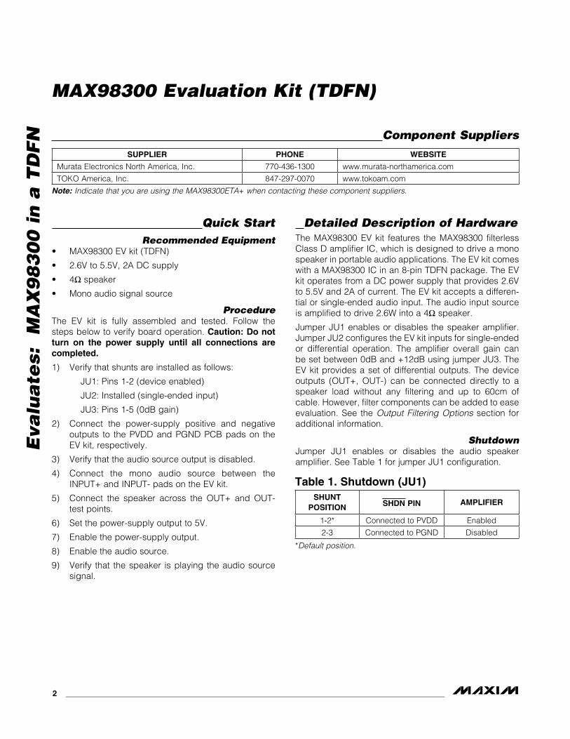
ShutdownJumper JU1 enables or disables the audio speaker amplifier. See Table 1 for jumper JU1 configuration.
Note: Indicate that you are using the MAX98300ETA+ when contacting these component suppliers.
*Default position.
Component Suppliers
Table 1. Shutdown (JU1)
SUPPLIER PHONE WEBSITE
Murata Electronics North America, Inc. 770-436-1300 www.murata-northamerica.com
TOKO America, Inc. 847-297-0070 www.tokoam.com
SHUNT POSITION SHDN PIN AMPLIFIER
1-2* Connected to PVDD Enabled
2-3 Connected to PGND Disabled
MAX98300 Evaluation Kit (TDFN)
Eva
lua
tes: M
AX
98
30
0 in
a T
DF
N
_______________________________________________________________________________________ 3
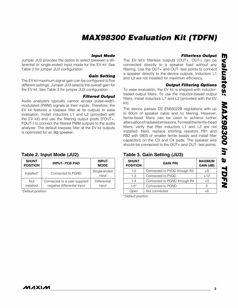
Input ModeJumper JU2 provides the option to select between a dif-ferential or single-ended input mode for the EV kit. See Table 2 for jumper JU2 configuration.
Gain SettingThe EV kit maximum signal gain can be configured to five different settings. Jumper JU3 selects the overall gain for the EV kit. See Table 3 for jumper JU3 configuration.
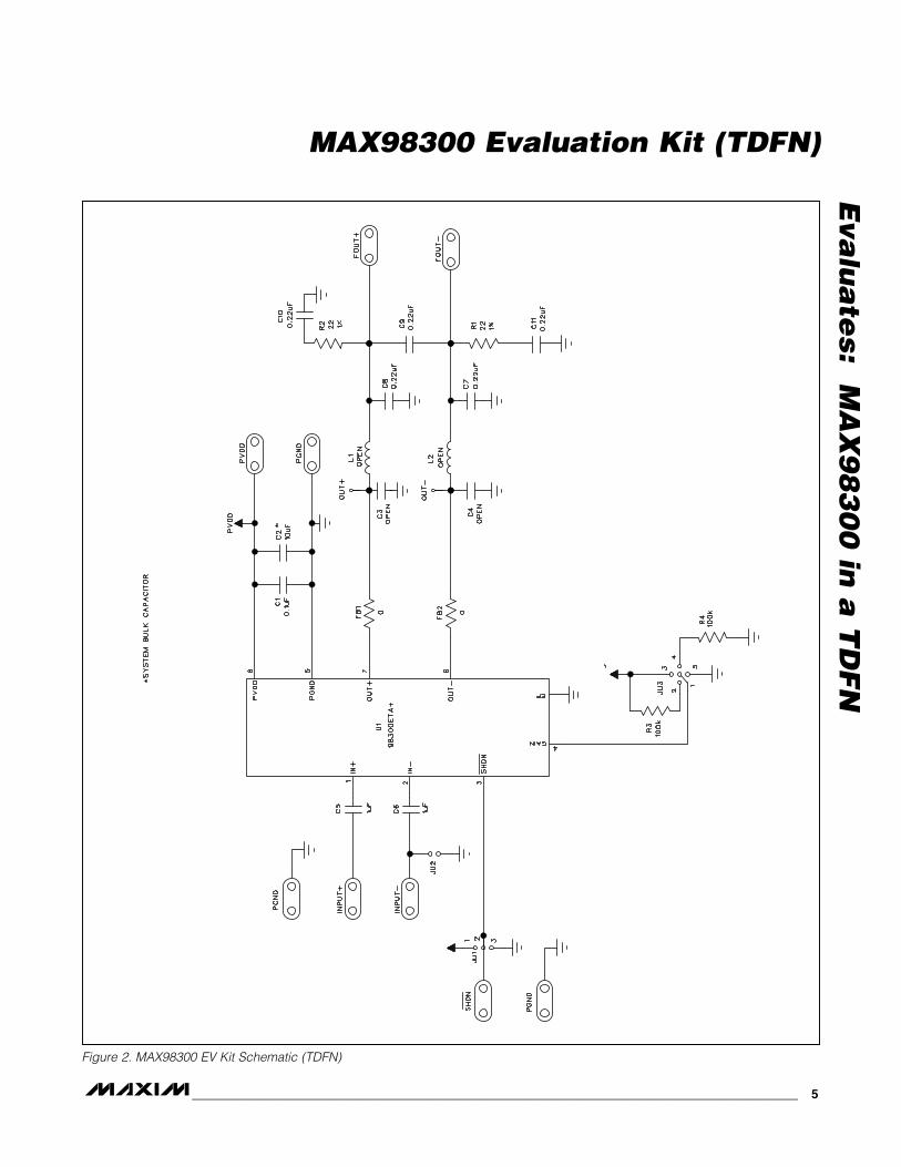
Filtered OutputAudio analyzers typically cannot accept pulse-width-modulated (PWM) signals at their inputs. Therefore, the EV kit features a lowpass filter at its outputs to ease evaluation. Install inductors L1 and L2 (provided with the EV kit) and use the filtering output posts (FOUT+, FOUT-) to connect the filtered PWM outputs to the audio analyzer. The default lowpass filter at the EV kit outputs is optimized for an 8I speaker.
Filterless OutputThe EV kit’s filterless outputs (OUT+, OUT-) can be connected directly to a speaker load without any filtering. Use the OUT+ and OUT- test points to connect a speaker directly to the device outputs. Inductors L1 and L2 are not installed for maximum efficiency.
Output Filtering OptionsTo ease evaluation, the EV kit is shipped with inductor-based output filters. To use the inductor-based output filters, install inductors L1 and L2 (provided with the EV kit).
The device passes CE EN55022B regulations with up to 60cm of speaker cable and no filtering. However, ferrite-bead filters can be used to achieve further attenuation of radiated emissions. To install the ferrite-bead filters, verify that filter inductors L1 and L2 are not installed. Next, replace shorting resistors FB1 and FB2 with 0805 or smaller ferrite beads and install filter capacitors on the C3 and C4 pads. The speaker wire should be connected to the OUT+ and OUT- test points.
*Default position.
*Default position.
Table 2. Input Mode (JU2) Table 3. Gain Setting (JU3)SHUNT
POSITIONINPUT- PCB PAD
INPUT MODE
Installed* Connected to PGND Single-ended
input
Not installed
Connected to a user-supplied negative differential input
Differential input
SHUNT POSITION
GAIN PINMAXIMUM GAIN (dB)
1-2 Connected to PVDD through R3 +9
1-3 Connected to PVDD +12
1-4 Connected to PGND through R4 +3
1-5* Connected to PGND 0
Open Not connected +6
MAX98300 Evaluation Kit (TDFN)
Eva
lua
tes:
M
AX
98
30
0 i
n a
TD
FN
4 ______________________________________________________________________________________
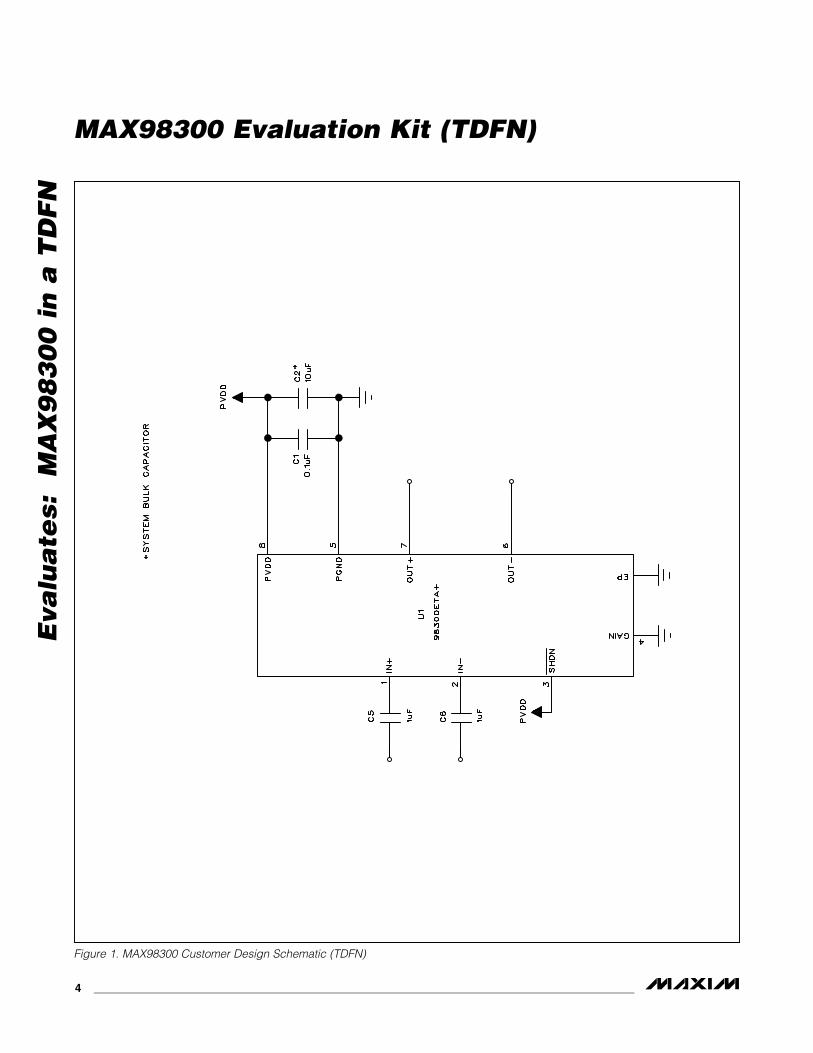
Figure 1. MAX98300 Customer Design Schematic (TDFN)
MAX98300 Evaluation Kit (TDFN)
Eva
lua
tes: M
AX
98
30
0 in
a T
DF
N
_______________________________________________________________________________________ 5
Figure 2. MAX98300 EV Kit Schematic (TDFN)
MAX98300 Evaluation Kit (TDFN)
Eva
lua
tes:
M
AX
98
30
0 i
n a
TD
FN
6 ______________________________________________________________________________________
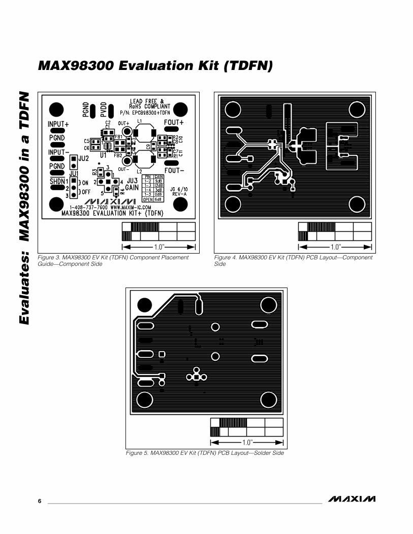
Figure 3. MAX98300 EV Kit (TDFN) Component Placement Guide—Component Side
Figure 4. MAX98300 EV Kit (TDFN) PCB Layout—Component Side
Figure 5. MAX98300 EV Kit (TDFN) PCB Layout—Solder Side
1.0’’ 1.0’’
1.0’’
Maxim cannot assume responsibility for use of any circuitry other than circuitry entirely embodied in a Maxim product. No circuit patent licenses are implied. Maxim reserves the right to change the circuitry and specifications without notice at any time.
Maxim Integrated Products, 120 San Gabriel Drive, Sunnyvale, CA 94086 408-737-7600 7© 2010 Maxim Integrated Products Maxim is a registered trademark of Maxim Integrated Products, Inc.
MAX98300 Evaluation Kit (TDFN)
Eva
lua
tes: M
AX
98
30
0 in
a T
DF
N
Revision History
REVISIONNUMBER
REVISION DATE
DESCRIPTIONPAGES
CHANGED
0 7/10 Initial release —