maxi lite® ml fcs series operator’s manualbidadoomedia.s3.amazonaws.com/pdf/allmand/maxi lite...
TRANSCRIPT

MAXI LITE® ML FCS SERIES
OPERATOR’S MANUAL
ALLMAND BROTHERS INC.
P.O. BOX 888
HOLDREGE, NE 68949
PHONE: (308) 995- 4495, 1- 800- 562- 1373
ALLMAND FAX: (308) 995– 5887
ALLMAND PARTS DEPT. FAX : (308) 995– 4883
WWW.allmand.com
PART NO. 103408 REVISED: APRIL 2012
RECORD IMPORTANT INFORMATION
2
Recording the equipment information will help, when placing an order for replacement parts and/ or decals.
Company Equipment No:
Unit model No:
Unit Vin:
Engine Model No: Serial No:
Generator Model No: Serial No:
Accessories:
3
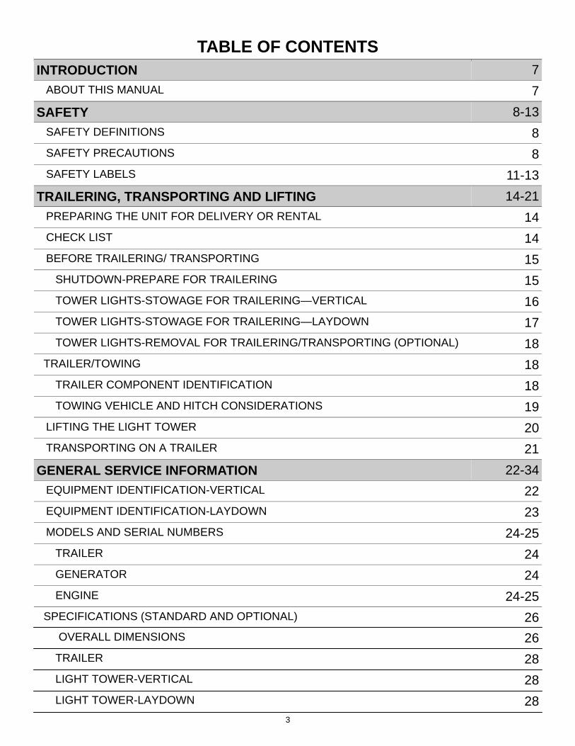
INTRODUCTION 7
ABOUT THIS MANUAL 7
SAFETY 8-13
SAFETY DEFINITIONS 8
SAFETY PRECAUTIONS 8
SAFETY LABELS 11-13
TRAILERING, TRANSPORTING AND LIFTING 14-21
PREPARING THE UNIT FOR DELIVERY OR RENTAL 14
CHECK LIST 14
BEFORE TRAILERING/ TRANSPORTING 15
SHUTDOWN-PREPARE FOR TRAILERING 15
TOWER LIGHTS-STOWAGE FOR TRAILERING—VERTICAL 16
TOWER LIGHTS-STOWAGE FOR TRAILERING—LAYDOWN 17
TOWER LIGHTS-REMOVAL FOR TRAILERING/TRANSPORTING (OPTIONAL) 18
TRAILER/TOWING 18
TRAILER COMPONENT IDENTIFICATION 18
TOWING VEHICLE AND HITCH CONSIDERATIONS 19
LIFTING THE LIGHT TOWER 20
TRANSPORTING ON A TRAILER 21
GENERAL SERVICE INFORMATION 22-34
EQUIPMENT IDENTIFICATION-VERTICAL 22
EQUIPMENT IDENTIFICATION-LAYDOWN 23
MODELS AND SERIAL NUMBERS 24-25
TRAILER 24
TABLE OF CONTENTS
GENERATOR 24
ENGINE 24-25
OVERALL DIMENSIONS 26
SPECIFICATIONS (STANDARD AND OPTIONAL) 26
TRAILER 28
LIGHT TOWER-VERTICAL 28
LIGHT TOWER-LAYDOWN 28
4
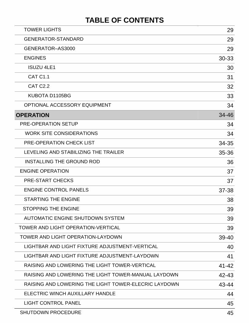
TOWER LIGHTS 29
GENERATOR-STANDARD 29
GENERATOR–AS3000 29
ENGINES 30-33
ISUZU 4LE1 30
CAT C1.1 31
CAT C2.2 32
OPTIONAL ACCESSORY EQUIPMENT 34
OPERATION 34-46
PRE-OPERATION SETUP 34
WORK SITE CONSIDERATIONS 34
PRE-OPERATION CHECK LIST 34-35
LEVELING AND STABILIZING THE TRAILER 35-36
INSTALLING THE GROUND ROD 36
ENGINE OPERATION 37
PRE-START CHECKS 37
ENGINE CONTROL PANELS 37-38
STARTING THE ENGINE 38
STOPPING THE ENGINE 39
AUTOMATIC ENGINE SHUTDOWN SYSTEM 39
TOWER AND LIGHT OPERATION-VERTICAL 39
TOWER AND LIGHT OPERATION-LAYDOWN 39-40
LIGHTBAR AND LIGHT FIXTURE ADJUSTMENT-VERTICAL 40
LIGHTBAR AND LIGHT FIXTURE ADJUSTMENT-LAYDOWN 41
RAISING AND LOWERING THE LIGHT TOWER-VERTICAL 41-42
RAISING AND LOWERING THE LIGHT TOWER-MANUAL LAYDOWN 42-43
RAISING AND LOWERING THE LIGHT TOWER-ELECRIC LAYDOWN 43-44
ELECTRIC WINCH AUXILLARY HANDLE 44
LIGHT CONTROL PANEL 45
SHUTDOWN PROCEDURE 45
TABLE OF CONTENTS
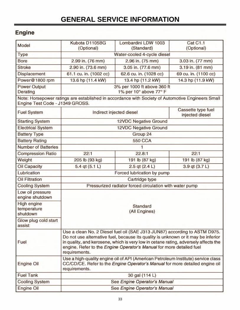
KUBOTA D1105BG 33
5
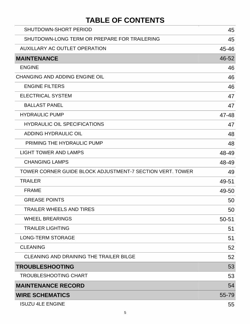
TABLE OF CONTENTS SHUTDOWN-SHORT PERIOD 45
SHUTDOWN-LONG TERM OR PREPARE FOR TRAILERING 45
AUXILLARY AC OUTLET OPERATION 45-46
MAINTENANCE 46-52
ENGINE 46
CHANGING AND ADDING ENGINE OIL 46
ENGINE FILTERS 46
ELECTRICAL SYSTEM 47
BALLAST PANEL 47
HYDRAULIC PUMP 47-48
HYDRAULIC OIL SPECIFICATIONS 47
ADDING HYDRAULIC OIL 48
PRIMING THE HYDRAULIC PUMP 48
LIGHT TOWER AND LAMPS 48-49
CHANGING LAMPS 48-49
TOWER CORNER GUIDE BLOCK ADJUSTMENT-7 SECTION VERT. TOWER 49
TRAILER 49-51
FRAME 49-50
GREASE POINTS 50
TRAILER WHEELS AND TIRES 50
WHEEL BREARINGS 50-51
TRAILER LIGHTING 51
LONG-TERM STORAGE 51
CLEANING 52
CLEANING AND DRAINING THE TRAILER BILGE 52
TROUBLESHOOTING 53
TROUBLESHOOTING CHART 53
MAINTENANCE RECORD 54
WIRE SCHEMATICS 55-79
ISUZU 4LE ENGINE 55
TABLE OF CONTENTS
6
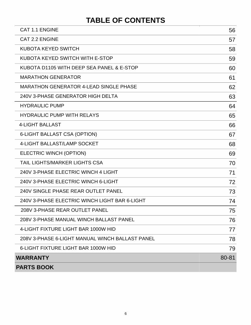
TABLE OF CONTENTS TABLE OF CONTENTS
CAT 2.2 ENGINE 57
MARATHON GENERATOR 61
MARATHON GENERATOR 4-LEAD SINGLE PHASE 62
240V 3-PHASE GENERATOR HIGH DELTA 63
HYDRAULIC PUMP 64
HYDRAULIC PUMP WITH RELAYS 65
4-LIGHT BALLAST 66
6-LIGHT BALLAST CSA (OPTION) 67
4-LIGHT BALLAST/LAMP SOCKET 68
ELECTRIC WINCH (OPTION) 69
TAIL LIGHTS/MARKER LIGHTS CSA 70
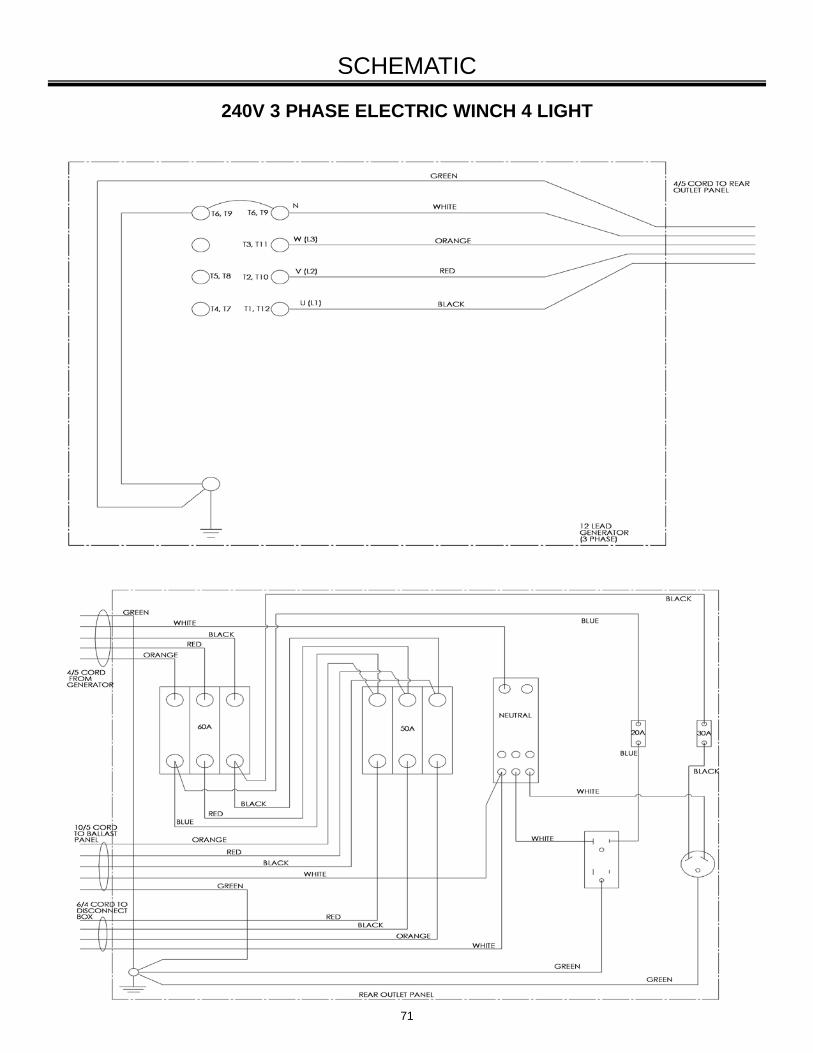
240V 3-PHASE ELECTRIC WINCH 4 LIGHT 71
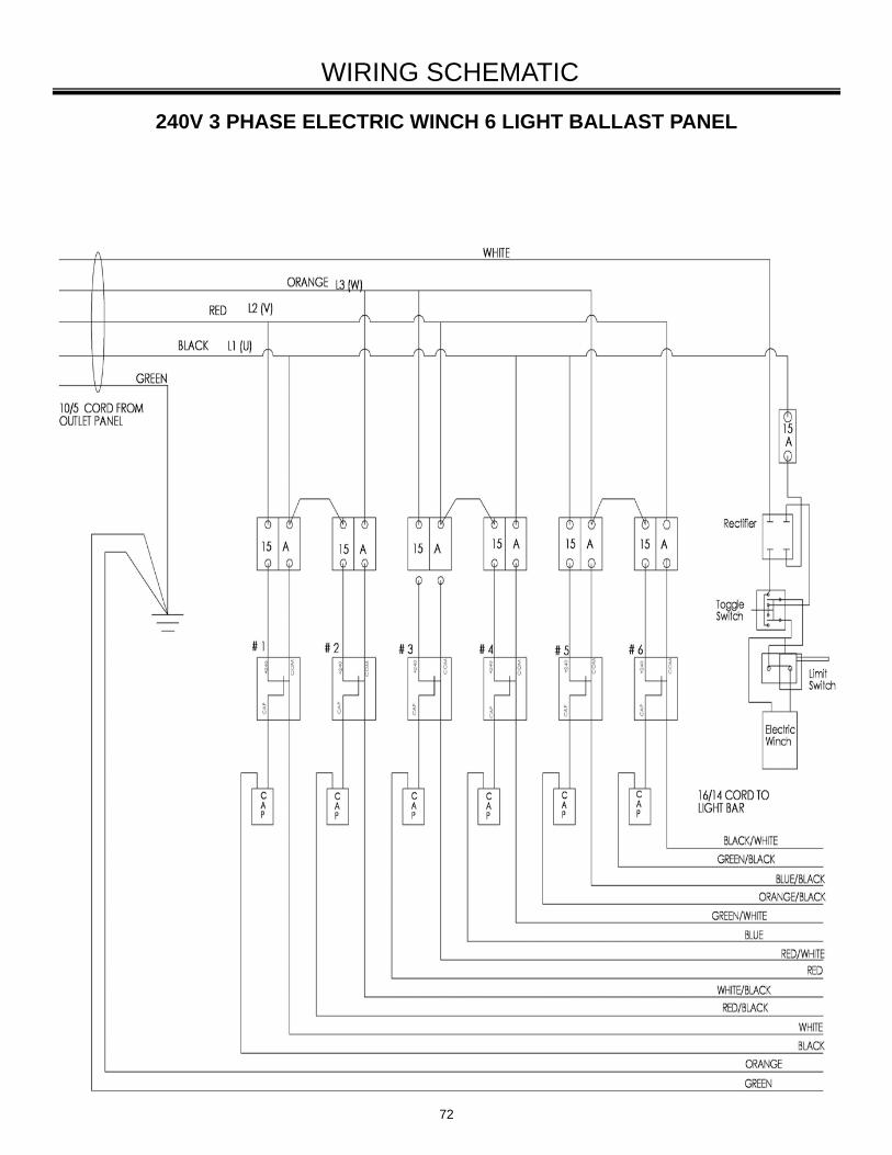
240V 3-PHASE ELECTRIC WINCH 6-LIGHT 72
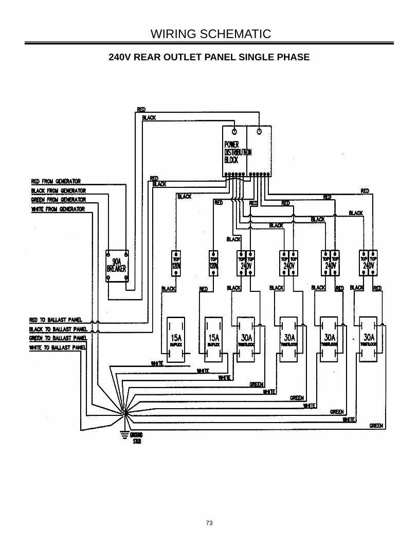
240V SINGLE PHASE REAR OUTLET PANEL 73
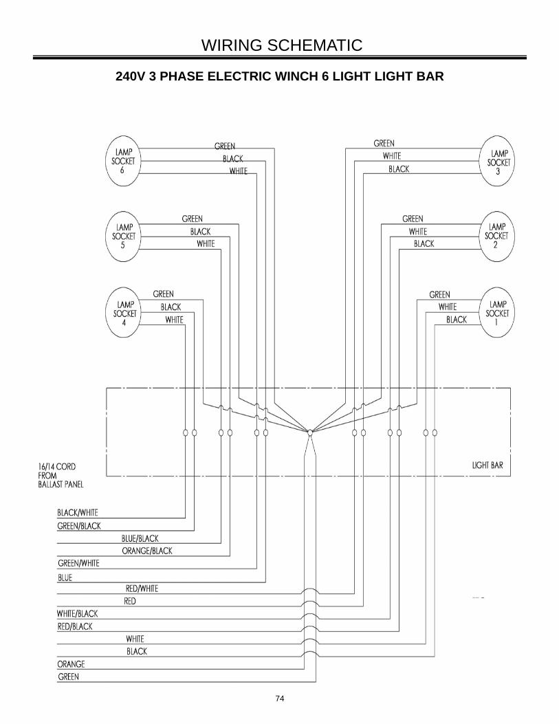
240V 3-PHASE ELECTRIC WINCH LIGHT BAR 6-LIGHT 74
208V 3-PHASE REAR OUTLET PANEL 75
208V 3-PHASE MANUAL WINCH BALLAST PANEL 76
4-LIGHT FIXTURE LIGHT BAR 1000W HID 77
208V 3-PHASE 6-LIGHT MANUAL WINCH BALLAST PANEL 78
CAT 1.1 ENGINE 56
6-LIGHT FIXTURE LIGHT BAR 1000W HID 79
WARRANTY 80-81
PARTS BOOK
KUBOTA KEYED SWITCH 58
KUBOTA KEYED SWITCH WITH E-STOP 59
KUBOTA D1105 WITH DEEP SEA PANEL & E-STOP 60
7
INTRODUCTION Congratulations on the purchase of your new Allmand MAXI-LITE ML FCS SERIES light tower and welcome to the Allmand Family of equipment owners.
The Allmand MAXI-LITE ML FCS SERIES light tower offers many advantages to make operation safer, more convenient and more cost effective. The MAXI-LITE ML FCS SERIES light tower will provide you with high quality performance and durability which translates into more productivity on the job site.
ABOUT THIS MANUAL
Take time to read this manual thoroughly.
This Operator’s Manual provides information necessary for the safe operation of the Allmand Bros. inc. MAXI-LITE ML FCS SERIES light tower.
The graphics and text in this manual generally describe the Allmand MAXI-LITE ML FCS SERIES light tower. Allmand light towers differ by model and optionally installed equipment. Your Allmand light tower may not exactly match the graphics and /or text descriptions in this manual.
If you are uncertain about any of the information in the manual, contact Allmand Service Depart-ment at 1-800-562-1373 or your Allmand dealer for clarification before operation.
Specific operating instructions and specifica-tions are contained in this publication to famil-iarize the operator and maintenance personnel with the correct and safe procedures necessary to maintain and operate the equipment.
Engine - specific operating instructions and specifications are contained in the engine owner’s manual provided in your owners kit. Always refer to the engine owner’s manual for operation and maintenance procedures.
NOTE: On the MAXI-LITE ML FCS SERIES Light Tower Trailer there are two styles of Vertical Tower mast: a 7-section Tower (older model) or a 6-section Tower (newer model) and there are two options of the Laydown Tower mast: a Manual Winch or an Electric Winch.
8
SAFETY
The safety messages that follow have DANGER level hazards.
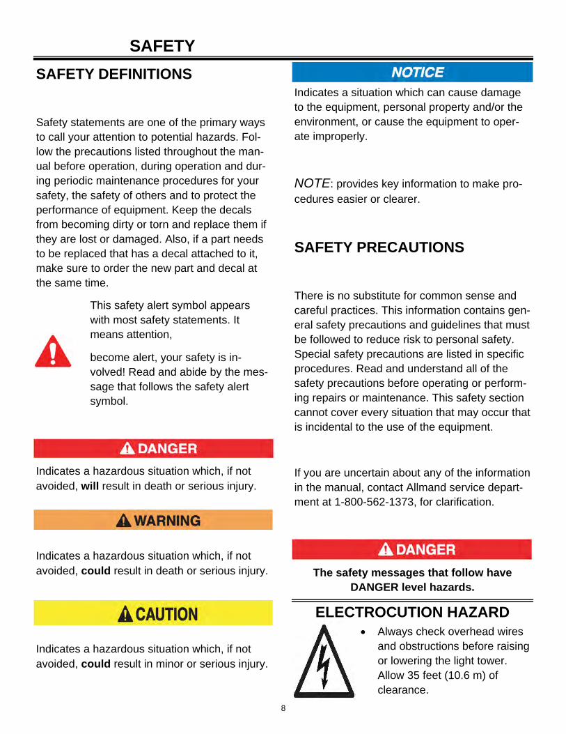
Always check overhead wires and obstructions before raising or lowering the light tower. Allow 35 feet (10.6 m) of clearance.
ELECTROCUTION HAZARD
SAFETY DEFINITIONS
Safety statements are one of the primary ways to call your attention to potential hazards. Fol-low the precautions listed throughout the man-ual before operation, during operation and dur-ing periodic maintenance procedures for your safety, the safety of others and to protect the performance of equipment. Keep the decals from becoming dirty or torn and replace them if they are lost or damaged. Also, if a part needs to be replaced that has a decal attached to it, make sure to order the new part and decal at the same time.
Indicates a hazardous situation which, if not avoided, will result in death or serious injury.
Indicates a hazardous situation which, if not avoided, could result in death or serious injury.
Indicates a hazardous situation which, if not avoided, could result in minor or serious injury.
This safety alert symbol appears with most safety statements. It means attention,
become alert, your safety is in-volved! Read and abide by the mes-sage that follows the safety alert symbol.
Indicates a situation which can cause damage to the equipment, personal property and/or the environment, or cause the equipment to oper-ate improperly.
NOTE: provides key information to make pro-cedures easier or clearer.
SAFETY PRECAUTIONS
There is no substitute for common sense and careful practices. This information contains gen-eral safety precautions and guidelines that must be followed to reduce risk to personal safety. Special safety precautions are listed in specific procedures. Read and understand all of the safety precautions before operating or perform-ing repairs or maintenance. This safety section cannot cover every situation that may occur that is incidental to the use of the equipment.
If you are uncertain about any of the information in the manual, contact Allmand service depart-ment at 1-800-562-1373, for clarification.
9
SAFETY
The safety messages that follow have WARNING level hazards.
High voltage is present when engine is running. Never attempt to service electrical components while engine is running.
Do not operate the light tower if the insulation on the electrical cord or other electrical wiring is cut or worn or if bare wires are exposed. Repair or replace damaged wiring before starting the engine.
Read and understand this Operator’s Manual, the Engine Operator’s Manual before operating or servicing the light tower to ensure that safe operating practices and maintenance procedures are followed.
UNSAFE OPERATION HAZARD
Never carry riders on the equipment
FALL HAZARD
MODIFICATION HAZARD
Never modify the equipment without written consent of the manufacturer. Any modification can effect the safe operation of the equipment.
EXPOSURE HAZARD Always wear personal protec-
tive equipment, including appropriate clothing, gloves, work shoes, and eye and hearing protection, as required by the task at hand.
ROLLOVER HAZARD Do not raise, lower or use light tower unless
all outriggers and jacks are positioned on firm ground.
Never move or reposition the light tower while the light tower is extended in the vertical position.
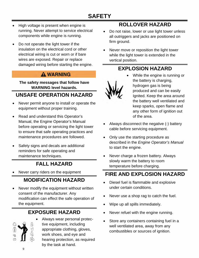
EXPLOSION HAZARD While the engine is running or
the battery is charging, hydrogen gas is being produced and can be easily Ignited. Keep the area around the battery well ventilated and keep sparks, open flame and any other form of ignition out of the area.
Always disconnect the negative (-) battery cable before servicing equipment.
Only use the starting procedure as described in the Engine Operator’s Manual to start the engine.
Never charge a frozen battery. Always slowly warm the battery to room temperature before charging.
FIRE AND EXPLOSION HAZARD
Diesel fuel is flammable and explosive under certain conditions.
Never use a shop rag to catch the fuel.
Wipe up all spills immediately.
Never refuel with the engine running.
Store any containers containing fuel in a well ventilated area, away from any combustibles or sources of ignition.
Never permit anyone to install or operate the equipment without proper training.
Safety signs and decals are additional reminders for safe operating and maintenance techniques.
10
SAFETY
The safety messages that follow have WARNING level hazards.
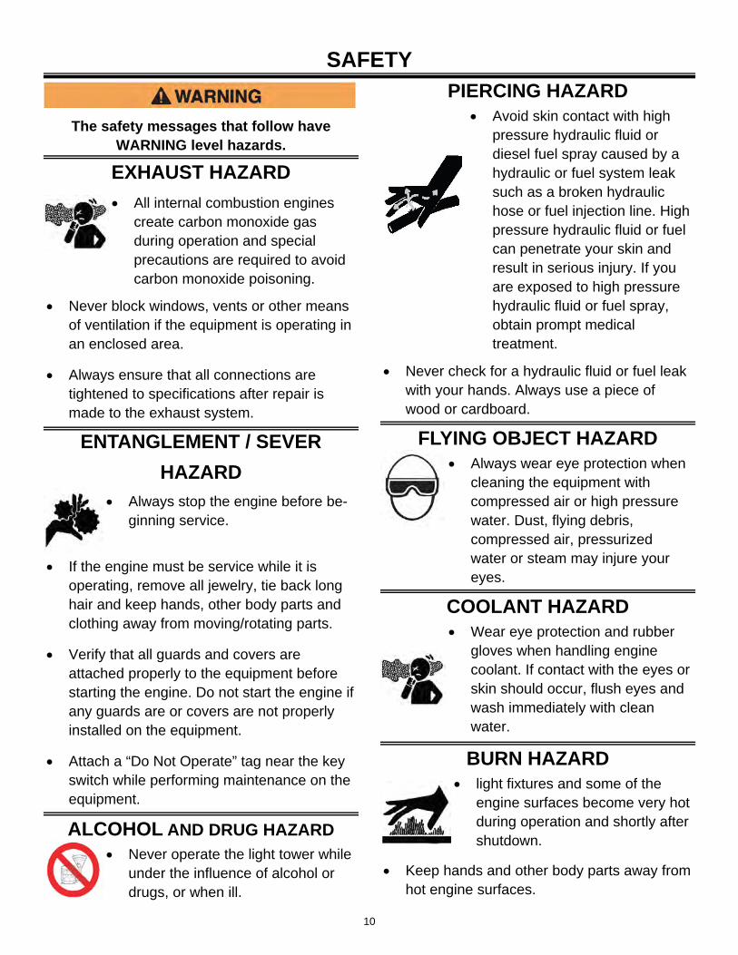
EXHAUST HAZARD
All internal combustion engines create carbon monoxide gas during operation and special precautions are required to avoid carbon monoxide poisoning.
Never block windows, vents or other means of ventilation if the equipment is operating in an enclosed area.
Always ensure that all connections are tightened to specifications after repair is made to the exhaust system.
ENTANGLEMENT / SEVER
HAZARD
Always stop the engine before be-ginning service.
If the engine must be service while it is operating, remove all jewelry, tie back long hair and keep hands, other body parts and clothing away from moving/rotating parts.
Verify that all guards and covers are attached properly to the equipment before starting the engine. Do not start the engine if any guards are or covers are not properly installed on the equipment.
Attach a “Do Not Operate” tag near the key switch while performing maintenance on the equipment.
ALCOHOL AND DRUG HAZARD
Never operate the light tower while under the influence of alcohol or drugs, or when ill.
PIERCING HAZARD Avoid skin contact with high
pressure hydraulic fluid or diesel fuel spray caused by a hydraulic or fuel system leak such as a broken hydraulic hose or fuel injection line. High pressure hydraulic fluid or fuel can penetrate your skin and result in serious injury. If you are exposed to high pressure hydraulic fluid or fuel spray, obtain prompt medical treatment.
Never check for a hydraulic fluid or fuel leak with your hands. Always use a piece of wood or cardboard.
FLYING OBJECT HAZARD Always wear eye protection when
cleaning the equipment with compressed air or high pressure water. Dust, flying debris, compressed air, pressurized water or steam may injure your eyes.
COOLANT HAZARD Wear eye protection and rubber
gloves when handling engine coolant. If contact with the eyes or skin should occur, flush eyes and wash immediately with clean water.
BURN HAZARD light fixtures and some of the
engine surfaces become very hot during operation and shortly after shutdown.
Keep hands and other body parts away from hot engine surfaces.
11
SAFETY
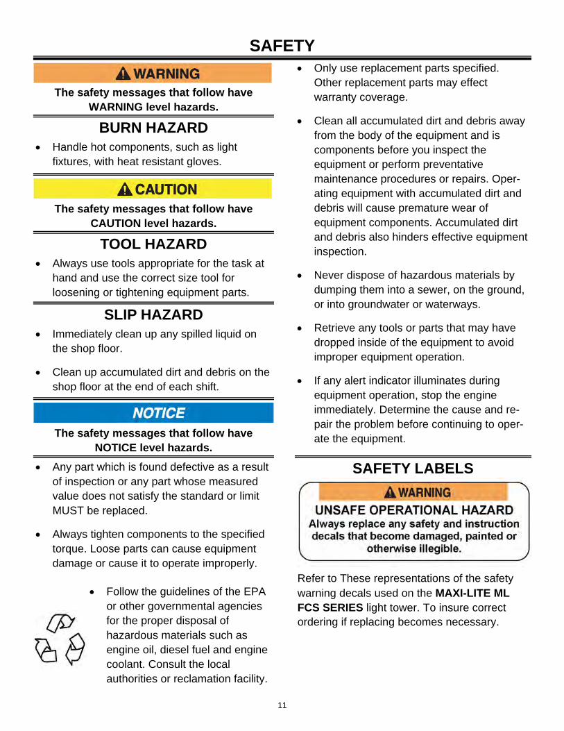
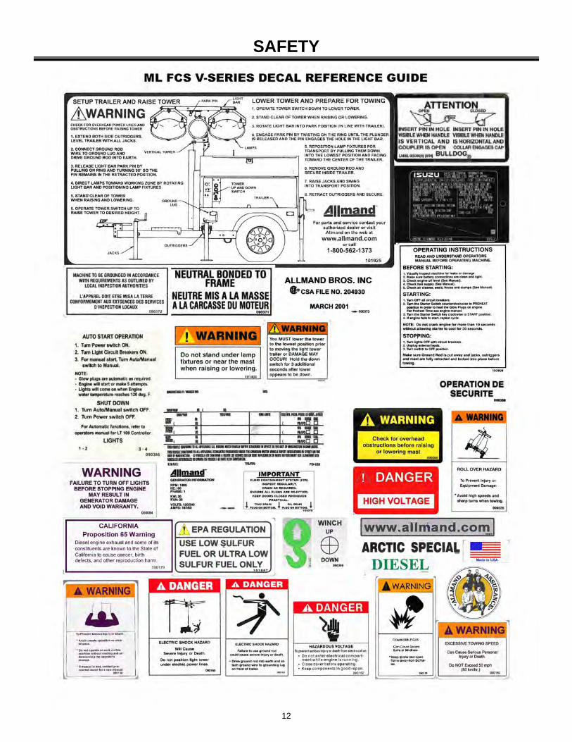
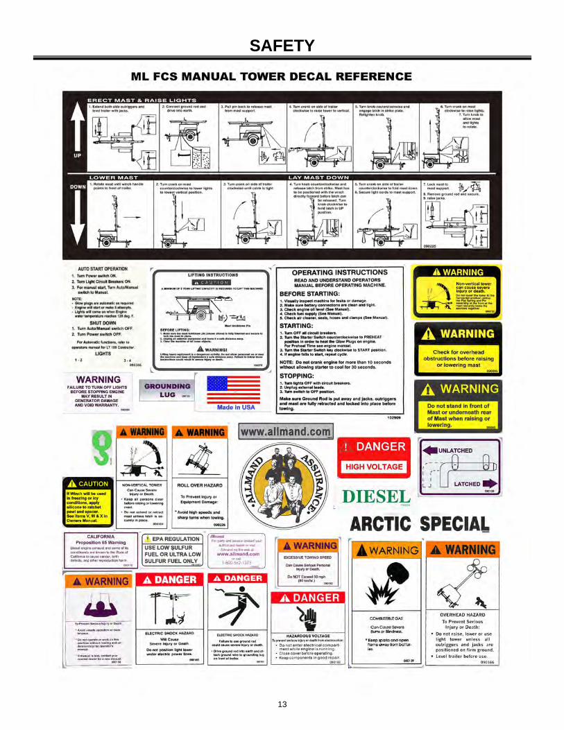
Refer to These representations of the safety warning decals used on the MAXI-LITE ML FCS SERIES light tower. To insure correct ordering if replacing becomes necessary.
The safety messages that follow have WARNING level hazards.
BURN HAZARD Handle hot components, such as light
fixtures, with heat resistant gloves.
The safety messages that follow have CAUTION level hazards.
TOOL HAZARD Always use tools appropriate for the task at
hand and use the correct size tool for loosening or tightening equipment parts.
SLIP HAZARD Immediately clean up any spilled liquid on
the shop floor.
Clean up accumulated dirt and debris on the shop floor at the end of each shift.
The safety messages that follow have NOTICE level hazards.
Any part which is found defective as a result of inspection or any part whose measured value does not satisfy the standard or limit MUST be replaced.
Always tighten components to the specified torque. Loose parts can cause equipment damage or cause it to operate improperly.
Only use replacement parts specified. Other replacement parts may effect warranty coverage.
Clean all accumulated dirt and debris away from the body of the equipment and is components before you inspect the equipment or perform preventative maintenance procedures or repairs. Oper-ating equipment with accumulated dirt and debris will cause premature wear of equipment components. Accumulated dirt and debris also hinders effective equipment inspection.
Never dispose of hazardous materials by dumping them into a sewer, on the ground, or into groundwater or waterways.
Retrieve any tools or parts that may have dropped inside of the equipment to avoid improper equipment operation.
If any alert indicator illuminates during equipment operation, stop the engine immediately. Determine the cause and re-pair the problem before continuing to oper-ate the equipment.
Follow the guidelines of the EPA or other governmental agencies for the proper disposal of hazardous materials such as engine oil, diesel fuel and engine coolant. Consult the local authorities or reclamation facility.
SAFETY LABELS
12
SAFETY
13
SAFETY
14
TRAILERING, TRANSPORTING AND LIFTING
PREPARING THE UNIT FOR DELIVERY OR RENTAL
The MAXI-LITE ML FCS SERIES light tower requires service as well as proper operation in order to provide the performance and safety it has been designed for. Never deliver or put machine into service with known defects or missing instructions or decals. Always instruct the customer in proper operation and safety procedures as described in this Operator’s Manual. Always provide the manual with the equipment for proper and safe operation.
CHECK LIST
Visually inspect the equipment to ensure that all instructions and decals are in place and legible.
Inspect the light tower locking bar latch assembly which locks the light tower in the vertical position for proper operation.
Check the hitch assembly and safety chains.
Check the outriggers and jacks to make sure they operate properly.
Inspect the light assemblies for damage and test for proper operation.
Inspect the electrical wiring for signs of damage.
Check ground rod cable and the ground lug. Make sure they are clean, undamaged and functional.
Inspect tires to insure good condition and proper inflation.
Check engine oil, fuel, engine coolant levels and hydraulic fluid levels, if equipped.
Check to make sure the Light Tower Operator’s Manual and Generator Operator’s Manual are with the equipment.
Inspect the machine physically for damage and repair if necessary.
ALWAYS READ AND UNDERSTAND THE
INSTRUCTIONS FIRST.
After completing the pre-operation check list, operate the tower through a complete operation cycle, following the operating instructions in the MAXI-LITE ML FCS SERIES Operator’s Manual.
15
TRAILERING, TRANSPORTING AND LIFTING Before trailering, transporting or lifting, read Safety on page 8.
The complete engine and generator set is housed in a lockable enclosure with the frame fabricated from heavy gauge steel mounted on a two-wheel, leaf spring axle.
BEFORE TRAILERING OR TRANS-PORTING
Perform the following before trailering / transporting:
Lower the light tower and shut down the tower lights and the engine; See Shutdown-prepare for trailering on page 15.
Visually inspect the trailer and equipment for damage. Repair or replace any components as needed before trailering.
Check the trailer lights for proper operation
Inspect the tires to insure good condition and proper inflation.
Inspect trailer springs and undercarriage for damage or loose parts.
Check the hitch assembly and safety chains.
Ensure the outriggers and jacks are properly stowed.
Ensure the ground rod and cable are disconnected and properly stowed.
Clean any spills from inside the trailer bilge area around the outside of the trailer; they may have occurred during operation.
Ensure all compartment doors are closed and securely locked.
SHUTDOWN - Prepare for trailering
1. With the tower lights off, lower the light tower to the full DOWN position; See Raising and lowering the light tower on page 38-41.
2. Turn the engine off . Refer to your Engine Operator’s Manual for stopping procedure.
3. Adjust the light bar and light fixtures for trailering; See Tower Lights-Stowage for trailering on page 16-17.
7. Raise each outrigger stabilizer jack and rotate into trailering position (horizontal with outrigger bar).
4. Secure the light cords into the hook on the rear tower support.(Laydown Tower Only)
5. Disconnect the ground rod cable rod the ground lug. Remove the ground rod from the earth and clean and secure the ground rod and cable in the trailer.
6. Close, secure and lock all compartment doors.
16
TRAILERING, TRANSPORTING AND LIFTING 8. Retract each outrigger bar and secure in the
stowed position with latch pin.
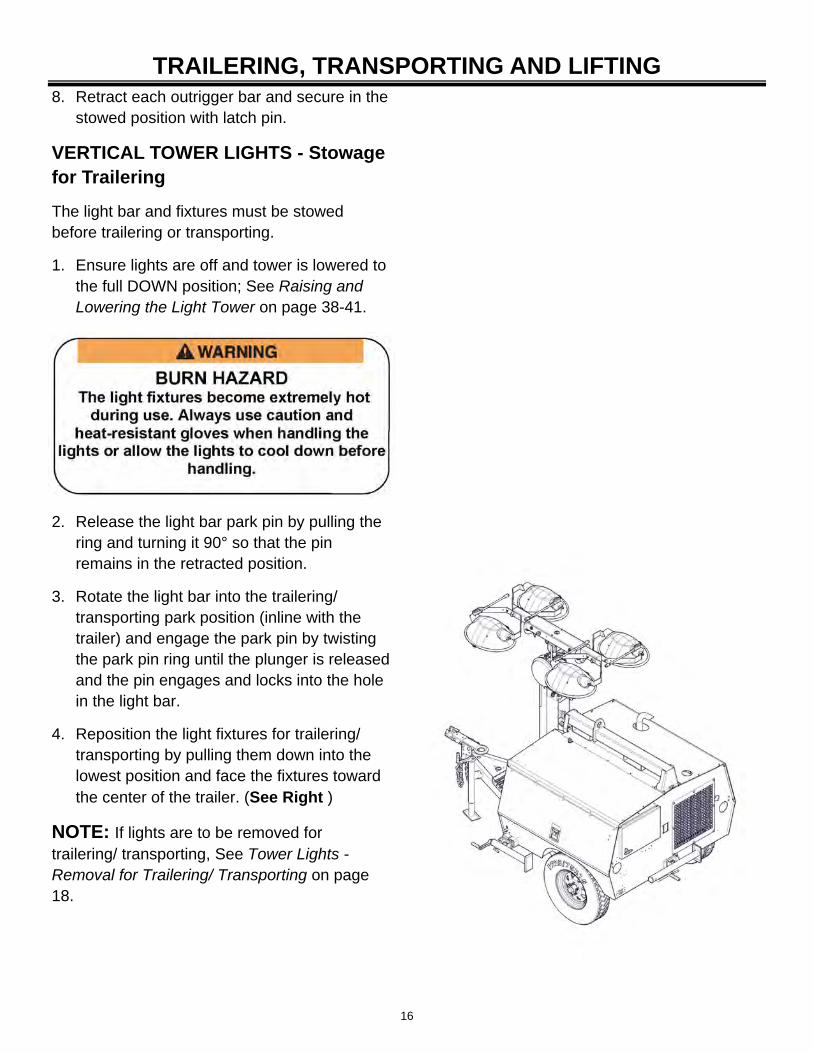
VERTICAL TOWER LIGHTS - Stowage for Trailering
The light bar and fixtures must be stowed before trailering or transporting.
1. Ensure lights are off and tower is lowered to the full DOWN position; See Raising and Lowering the Light Tower on page 38-41.
2. Release the light bar park pin by pulling the ring and turning it 90° so that the pin remains in the retracted position.
3. Rotate the light bar into the trailering/ transporting park position (inline with the trailer) and engage the park pin by twisting the park pin ring until the plunger is released and the pin engages and locks into the hole in the light bar.
4. Reposition the light fixtures for trailering/ transporting by pulling them down into the lowest position and face the fixtures toward the center of the trailer. (See Right )
NOTE: If lights are to be removed for trailering/ transporting, See Tower Lights - Removal for Trailering/ Transporting on page 18.
17
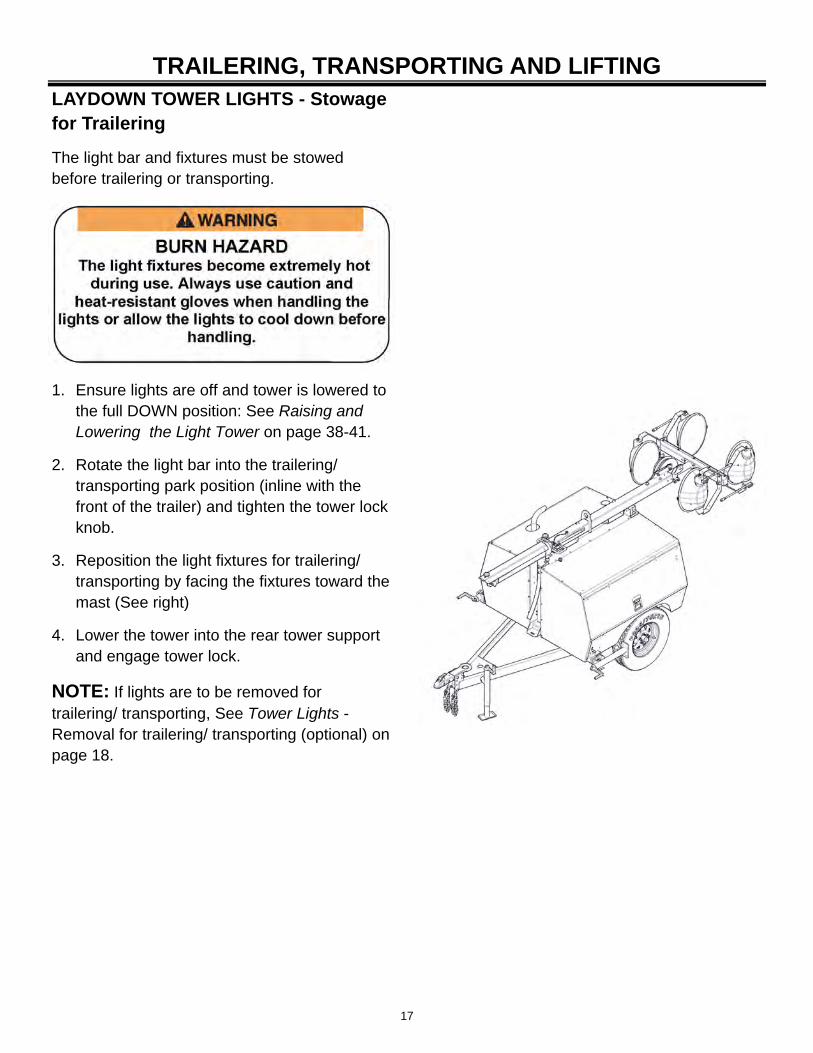
TRAILERING, TRANSPORTING AND LIFTING LAYDOWN TOWER LIGHTS - Stowage for Trailering
The light bar and fixtures must be stowed before trailering or transporting.
1. Ensure lights are off and tower is lowered to the full DOWN position: See Raising and Lowering the Light Tower on page 38-41.
2. Rotate the light bar into the trailering/ transporting park position (inline with the front of the trailer) and tighten the tower lock knob.
3. Reposition the light fixtures for trailering/ transporting by facing the fixtures toward the mast (See right)
4. Lower the tower into the rear tower support and engage tower lock.
NOTE: If lights are to be removed for trailering/ transporting, See Tower Lights - Removal for trailering/ transporting (optional) on page 18.
18
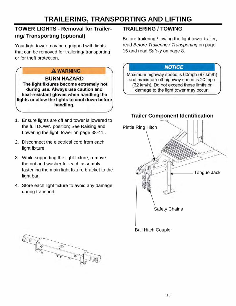
TRAILERING, TRANSPORTING AND LIFTING TRAILERING / TOWING
Before trailering / towing the light tower trailer, read Before Trailering / Transporting on page 15 and read Safety on page 8.
TOWER LIGHTS - Removal for Trailer-ing/ Transporting (optional)
Your light tower may be equipped with lights that can be removed for trailering/ transporting or for theft protection.
Tongue Jack
Pintle Ring Hitch
Ball Hitch Coupler
Safety Chains
Trailer Component Identification 1. Ensure lights are off and tower is lowered to
the full DOWN position; See Raising and Lowering the light tower on page 38-41 .
2. Disconnect the electrical cord from each light fixture.
3. While supporting the light fixture, remove the nut and washer for each assembly fastening the main light fixture bracket to the light bar.
4. Store each light fixture to avoid any damage during transport
19
TRAILERING, TRANSPORTING AND LIFTING Towing Vehicle and Hitch Considera-tions
The vehicle must have a towing hitch that is ca-pable of safely handling the trailer load and tongue weight of the trailer.
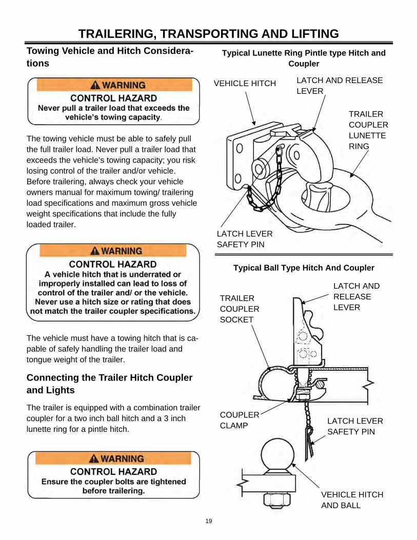
Connecting the Trailer Hitch Coupler and Lights
The trailer is equipped with a combination trailer coupler for a two inch ball hitch and a 3 inch lunette ring for a pintle hitch.
The towing vehicle must be able to safely pull the full trailer load. Never pull a trailer load that exceeds the vehicle’s towing capacity; you risk losing control of the trailer and/or vehicle. Before trailering, always check your vehicle owners manual for maximum towing/ trailering load specifications and maximum gross vehicle weight specifications that include the fully loaded trailer.
LATCH AND RELEASE LEVER
TRAILER COUPLER LUNETTE RING
LATCH LEVER SAFETY PIN
VEHICLE HITCH
Typical Lunette Ring Pintle type Hitch and Coupler
Typical Ball Type Hitch And Coupler
LATCH AND RELEASE LEVER
TRAILER COUPLER SOCKET
COUPLER CLAMP
LATCH LEVER SAFETY PIN
VEHICLE HITCH AND BALL
20
The trailer coupler must be reversed to use either the ball or lunette hitch coupler. To reverse the coupler, remove the two bolts and reposition the coupler as needed.
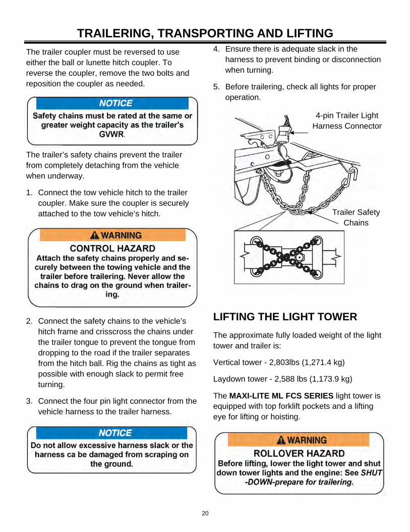
4. Ensure there is adequate slack in the harness to prevent binding or disconnection when turning.
5. Before trailering, check all lights for proper operation.
The trailer’s safety chains prevent the trailer from completely detaching from the vehicle when underway.
1. Connect the tow vehicle hitch to the trailer coupler. Make sure the coupler is securely attached to the tow vehicle’s hitch.
2. Connect the safety chains to the vehicle’s hitch frame and crisscross the chains under the trailer tongue to prevent the tongue from dropping to the road if the trailer separates from the hitch ball. Rig the chains as tight as possible with enough slack to permit free turning.
3. Connect the four pin light connector from the vehicle harness to the trailer harness.
TRAILERING, TRANSPORTING AND LIFTING
4-pin Trailer Light Harness Connector
Trailer Safety Chains
LIFTING THE LIGHT TOWER
The approximate fully loaded weight of the light tower and trailer is:
Vertical tower - 2,803lbs (1,271.4 kg)
Laydown tower - 2,588 lbs (1,173.9 kg)
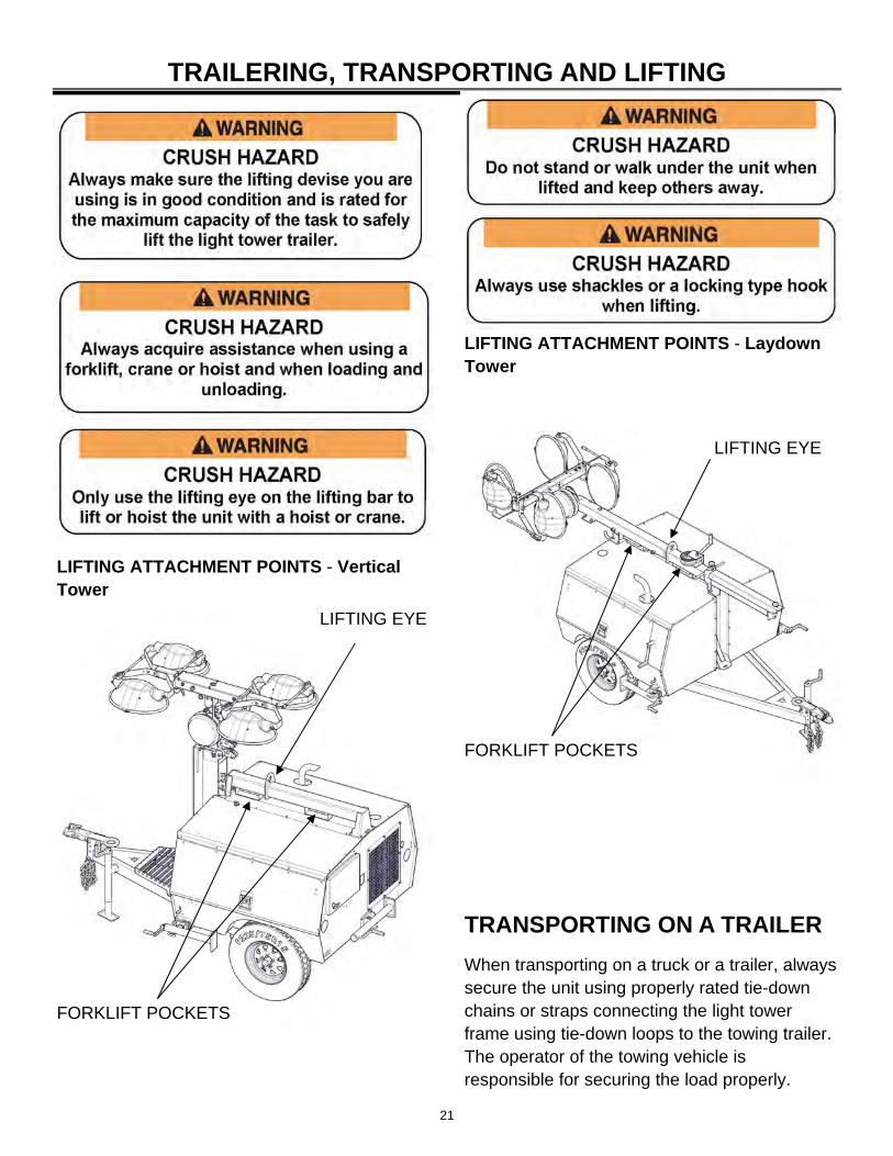
The MAXI-LITE ML FCS SERIES light tower is equipped with top forklift pockets and a lifting eye for lifting or hoisting.
21
TRAILERING, TRANSPORTING AND LIFTING
LIFTING ATTACHMENT POINTS - Vertical Tower
LIFTING ATTACHMENT POINTS - Laydown Tower
LIFTING EYE
FORKLIFT POCKETS
TRANSPORTING ON A TRAILER
When transporting on a truck or a trailer, always secure the unit using properly rated tie-down chains or straps connecting the light tower frame using tie-down loops to the towing trailer. The operator of the towing vehicle is responsible for securing the load properly.
LIFTING EYE
FORKLIFT POCKETS
22
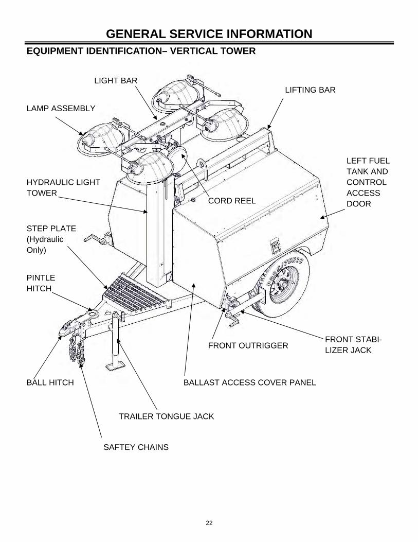
GENERAL SERVICE INFORMATION EQUIPMENT IDENTIFICATION– VERTICAL TOWER
LIFTING BAR LIGHT BAR
LAMP ASSEMBLY
CORD REEL
LEFT FUEL TANK AND CONTROL ACCESS DOOR
HYDRAULIC LIGHT TOWER
FRONT STABI-LIZER JACK
FRONT OUTRIGGER
TRAILER TONGUE JACK
BALL HITCH
PINTLE HITCH
STEP PLATE (Hydraulic Only)
SAFTEY CHAINS
BALLAST ACCESS COVER PANEL
23
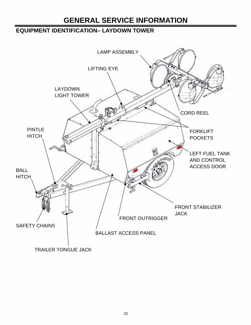
GENERAL SERVICE INFORMATION EQUIPMENT IDENTIFICATION– LAYDOWN TOWER
LIFTING EYE
LAMP ASSEMBLY
CORD REEL
LAYDOWN LIGHT TOWER
FORKLIFT POCKETS
LEFT FUEL TANK AND CONTROL ACCESS DOOR
FRONT STABILIZER JACK
FRONT OUTRIGGER
BALLAST ACCESS PANEL
PINTLE HITCH
BALL HITCH
SAFETY CHAINS
TRAILER TONGUE JACK
24
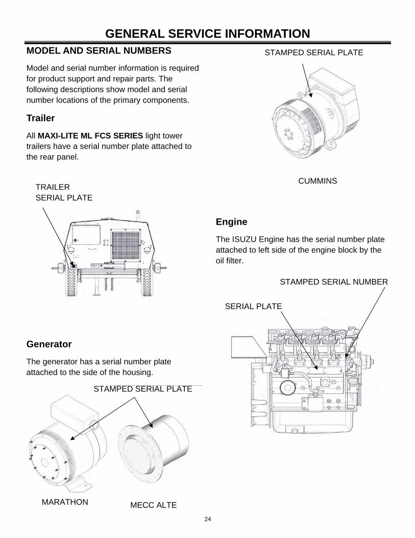
GENERAL SERVICE INFORMATION MODEL AND SERIAL NUMBERS
Model and serial number information is required for product support and repair parts. The following descriptions show model and serial number locations of the primary components.
Trailer
All MAXI-LITE ML FCS SERIES light tower trailers have a serial number plate attached to the rear panel.
TRAILER SERIAL PLATE
STAMPED SERIAL PLATE
Generator
The generator has a serial number plate attached to the side of the housing.
MARATHON MECC ALTE
STAMPED SERIAL PLATE
Engine
The ISUZU Engine has the serial number plate attached to left side of the engine block by the oil filter.
STAMPED SERIAL NUMBER
SERIAL PLATE
CUMMINS
25
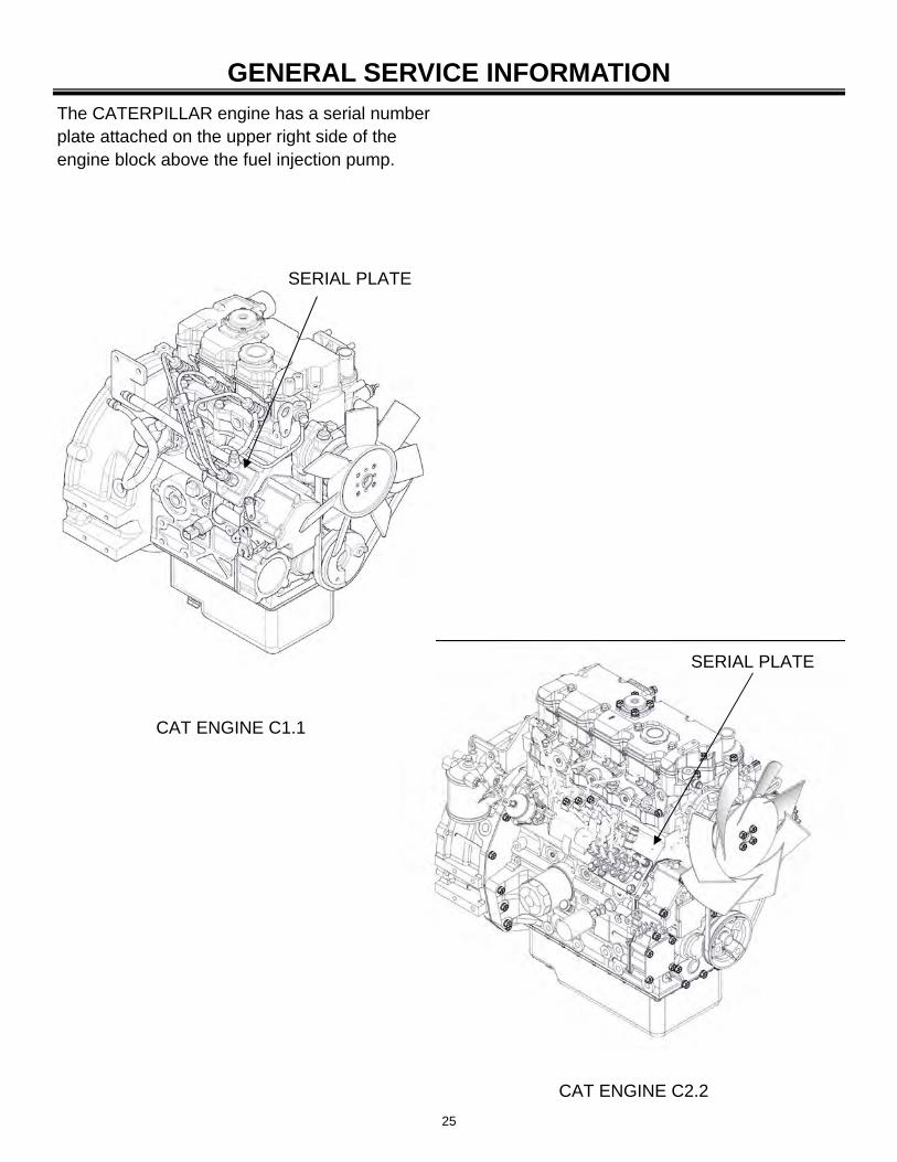
GENERAL SERVICE INFORMATION
SERIAL PLATE
The CATERPILLAR engine has a serial number plate attached on the upper right side of the engine block above the fuel injection pump.
CAT ENGINE C1.1
SERIAL PLATE
CAT ENGINE C2.2
26
GENERAL SERVICE INFORMATION
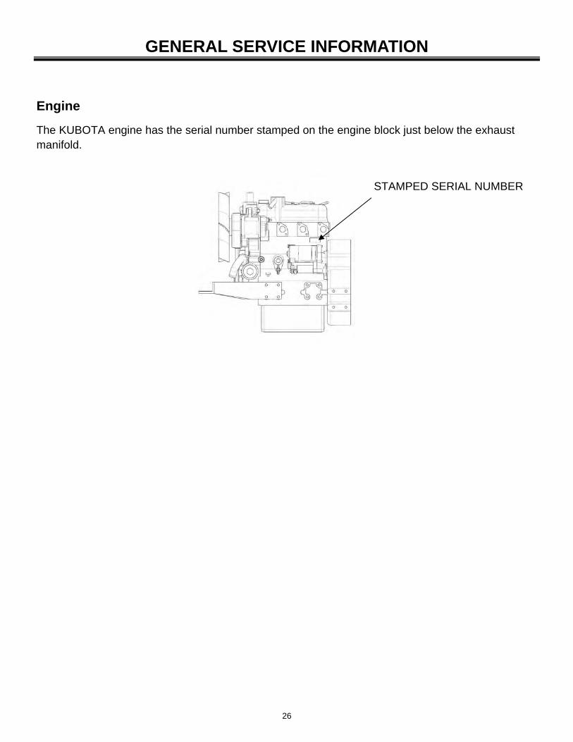
Engine
The KUBOTA engine has the serial number stamped on the engine block just below the exhaust manifold.
STAMPED SERIAL NUMBER
27
GENERAL SERVICE INFORMATION
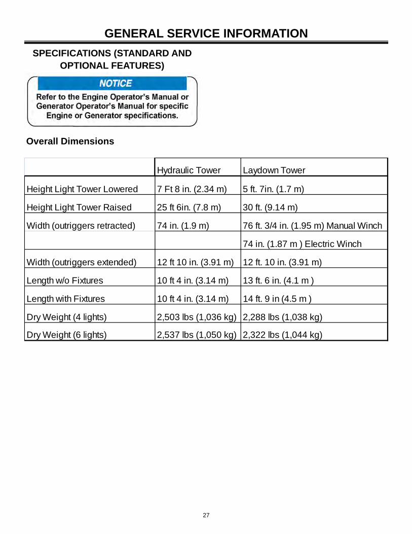
SPECIFICATIONS (STANDARD AND OPTIONAL FEATURES)
Hydraulic Tower Laydown Tower
Height Light Tower Lowered 7 Ft 8 in. (2.34 m) 5 ft. 7in. (1.7 m)
Height Light Tower Raised 25 ft 6in. (7.8 m) 30 ft. (9.14 m)
Width (outriggers retracted) 74 in. (1.9 m) 76 ft. 3/4 in. (1.95 m) Manual Winch
74 in. (1.87 m ) Electric Winch
Width (outriggers extended) 12 ft 10 in. (3.91 m) 12 ft. 10 in. (3.91 m)
Length w/o Fixtures 10 ft 4 in. (3.14 m) 13 ft. 6 in. (4.1 m )
Length with Fixtures 10 ft 4 in. (3.14 m) 14 ft. 9 in (4.5 m )
Dry Weight (4 lights) 2,503 lbs (1,036 kg) 2,288 lbs (1,038 kg)
Dry Weight (6 lights) 2,537 lbs (1,050 kg) 2,322 lbs (1,044 kg)
Overall Dimensions
28
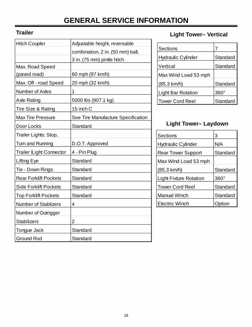
Hitch Coupler Adjustable height, reversable
combination, 2 in. (50 mm) ball,
3 in. (75 mm) pintle hitch
Max. Road Speed
(paved road) 60 mph (97 km/h)
Max. Off - road Speed 20 mph (32 km/h)
Number of Axles 1
Axle Rating 5000 lbs (907.1 kg)
Tire Size & Rating 15 inch C
Max Tire Pressure See Tire Manufacture Specification
Door Locks Standard
Trailer Lights: Stop,
Turn and Running D.O.T. Approved
Trailer lLight Connector 4 - Pin Plug
Lifting Eye Standard
Tie - Down Rings Standard
Rear Forklift Pockets Standard
Side Forklift Pockets Standard
Top Forklift Pockets Standard
Number of Stablizers 4
Number of Outrigger
Stabilizers 2
Tongue Jack Standard
Ground Rod Standard
Trailer
Light Tower– Laydown
Light Tower– Vertical
Sections 7
Hydraulic Cylinder Standard
Vertical Standard
Max Wind Load 53 mph
(85.3 km/h) Standard
Light Bar Rotation 360°
Tower Cord Reel Standard
GENERAL SERVICE INFORMATION
Sections 3
Hydraulic Cylinder N/A
Rear Tower Support Standard
Max Wind Load 53 mph
(85.3 km/h) Standard
Light Fixture Rotation 360°
Tower Cord Reel Standard
Manual Winch Standard
Electric Winch Option
29
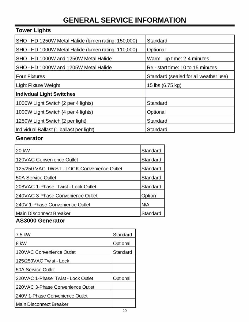
GENERAL SERVICE INFORMATION Tower Lights
SHO - HD 1250W Metal Halide (lumen rating: 150,000) Standard
SHO - HD 1000W Metal Halide (lumen rating: 110,000) Optional
SHO - HD 1000W and 1250W Metal Halide Warm - up time: 2-4 minutes
SHO - HD 1000W and 1205W Metal Halide Re - start time: 10 to 15 minutes
Four Fixtures Standard (sealed for all weather use)
Light Fixture Weight 15 lbs (6.75 kg)
Indivdual Light Switches
1000W Light Switch (2 per 4 lights) Standard
1000W Light Switch (4 per 4 lights) Optional
1250W Light Switch (2 per light) Standard
Individual Ballast (1 ballast per light) Standard
Generator
20 kW Standard
120VAC Convenience Outlet Standard
125/250 VAC TWIST - LOCK Convenience Outlet Standard
50A Service Outlet Standard
208VAC 1-Phase Twist - Lock Outlet Standard
240VAC 3-Phase Convenience Outlet Option
240V 1-Phase Convenience Outlet N/A
Main Disconnect Breaker Standard
AS3000 Generator
7.5 kW Standard
8 kW Optional
120VAC Convenience Outlet Standard
125/250VAC Twist - Lock
50A Service Outlet
220VAC 1-Phase Twist - Lock Outlet Optional
220VAC 3-Phase Convenience Outlet
240V 1-Phase Convenience Outlet
Main Disconnect Breaker
30
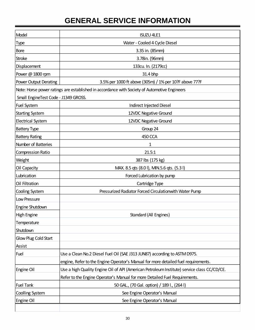
GENERAL SERVICE INFORMATION
Model ISUZU 4LE1
Type Water ‐ Cooled 4 Cycle Diesel
Bore 3.35 in. (85mm)
Stroke 3.78in. (96mm)
Displacement 133cu. In. (2179cc)
Power @ 1800 rpm 31.4 bhp
Power Output Derating 3.5% per 1000 ft above (305m) / 1% per 10?F above 77?F
Note: Horse power ratings are established in accordance with Society of Automotive Engineers
Small EngineTest Code ‐ J1349 GROSS.
Fuel System Indirect Injected Diesel
Starting System 12VDC Negative Ground
Electrical System 12VDC Negative Ground
Battery Type Group 24
Battery Rating 450 CCA
Number of Batteries 1
Compression Ratio 21.5:1
Weight 387 lbs (175 kg)
Oil Capacity MAX. 8.5 qts (8.0 l), MIN.5.6 qts. (5.3 l)
Lubrication Forced Lubrication by pump
Oil Filtration Cartridge Type
Cooling System Pressurized Radiator Forced Circulationwith Water Pump
Low Pressure
Engine Shutdown
High Engine Standard (All Engines)
Temperature
Shutdown
Glow Plug Cold Start
Assist
Fuel Use a Clean No.2 Diesel Fuel Oil (SAE J313 JUN87) according to ASTM D975.
engine, Refer to the Engine Operator's Manual for more detailed fuel requirements.
Engine Oil Use a high Quality Engine Oil of API (American Petroleum Institute) service class CC/CD/CE.
Refer to the Engine Operator's Manual for more Detailed Fuel Requirements.
Fuel Tank 50 GAL., (70 Gal. option) / 189 l., (264 l)
Coolling System See Engine Operator's Manual
Engine Oil See Engine Operator's Manual
31
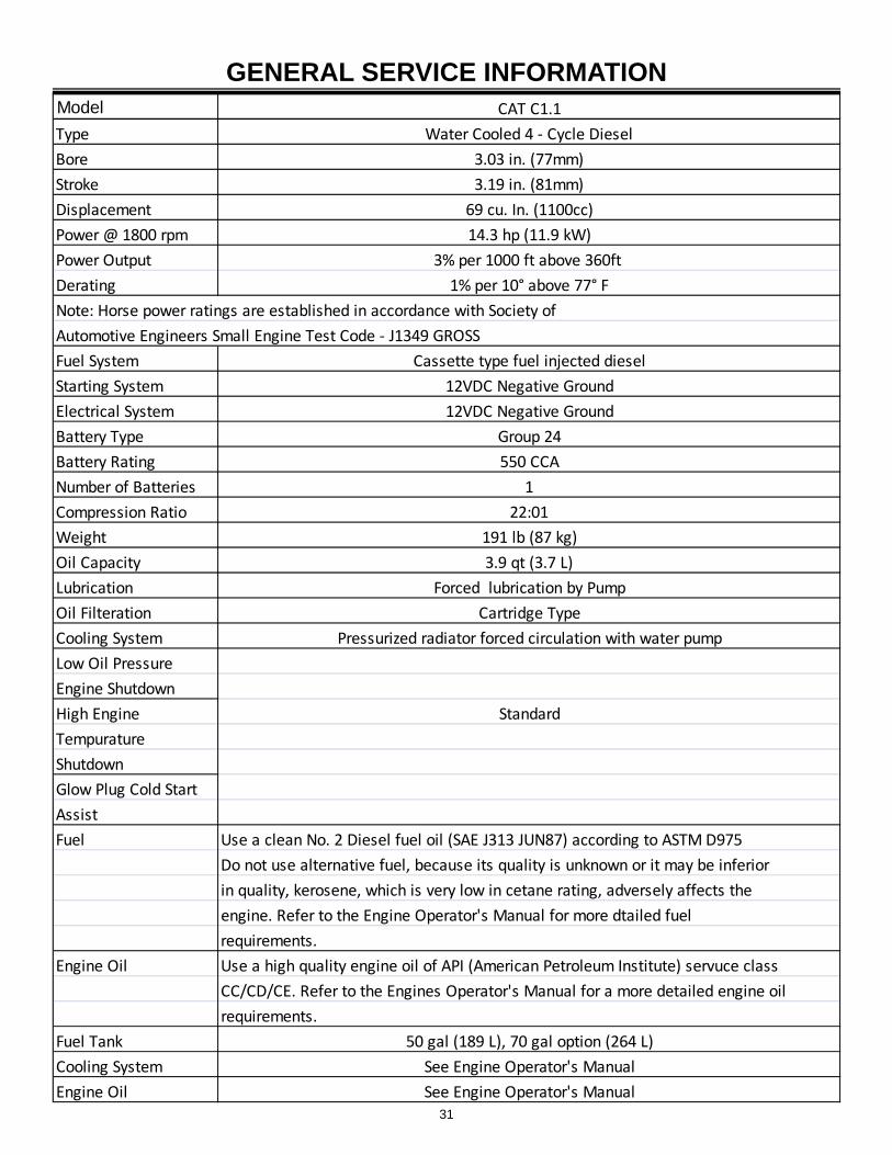
GENERAL SERVICE INFORMATION Model CAT C1.1
Type Water Cooled 4 ‐ Cycle Diesel
Bore 3.03 in. (77mm)
Stroke 3.19 in. (81mm)
Displacement 69 cu. In. (1100cc)
Power @ 1800 rpm 14.3 hp (11.9 kW)
Power Output 3% per 1000 ft above 360ft
Derating 1% per 10° above 77° F
Note: Horse power ratings are established in accordance with Society of
Automotive Engineers Small Engine Test Code ‐ J1349 GROSS
Fuel System Cassette type fuel injected diesel
Starting System 12VDC Negative Ground
Electrical System 12VDC Negative Ground
Battery Type Group 24
Battery Rating 550 CCA
Number of Batteries 1
Compression Ratio 22:01
Weight 191 lb (87 kg)
Oil Capacity 3.9 qt (3.7 L)
Lubrication Forced lubrication by Pump
Oil Filteration Cartridge Type
Cooling System Pressurized radiator forced circulation with water pump
Low Oil Pressure
Engine Shutdown
High Engine Standard
Tempurature
Shutdown
Glow Plug Cold Start
Assist
Fuel Use a clean No. 2 Diesel fuel oil (SAE J313 JUN87) according to ASTM D975
Do not use alternative fuel, because its quality is unknown or it may be inferior
in quality, kerosene, which is very low in cetane rating, adversely affects the
engine. Refer to the Engine Operator's Manual for more dtailed fuel
requirements.
Engine Oil Use a high quality engine oil of API (American Petroleum Institute) servuce class
CC/CD/CE. Refer to the Engines Operator's Manual for a more detailed engine oil
requirements.
Fuel Tank 50 gal (189 L), 70 gal option (264 L)
Cooling System See Engine Operator's Manual
Engine Oil See Engine Operator's Manual
32
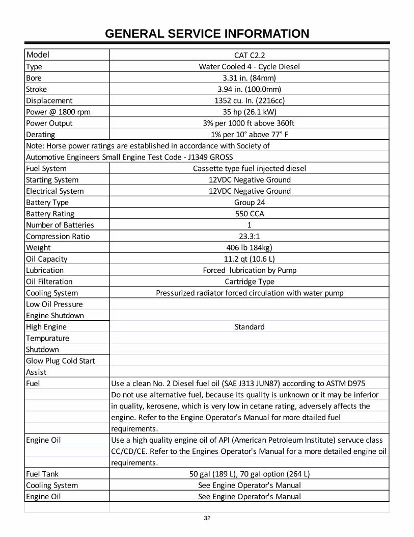
Model CAT C2.2
Type Water Cooled 4 ‐ Cycle Diesel
Bore 3.31 in. (84mm)
Stroke 3.94 in. (100.0mm)
Displacement 1352 cu. In. (2216cc)
Power @ 1800 rpm 35 hp (26.1 kW)
Power Output 3% per 1000 ft above 360ft
Derating 1% per 10° above 77° F
Note: Horse power ratings are established in accordance with Society of
Automotive Engineers Small Engine Test Code ‐ J1349 GROSS
Fuel System Cassette type fuel injected diesel
Starting System 12VDC Negative Ground
Electrical System 12VDC Negative Ground
Battery Type Group 24
Battery Rating 550 CCA
Number of Batteries 1
Compression Ratio 23.3:1
Weight 406 lb 184kg)
Oil Capacity 11.2 qt (10.6 L)
Lubrication Forced lubrication by Pump
Oil Filteration Cartridge Type
Cooling System Pressurized radiator forced circulation with water pump
Low Oil Pressure
Engine Shutdown
High Engine Standard
Tempurature
Shutdown
Glow Plug Cold Start
Assist
Fuel Use a clean No. 2 Diesel fuel oil (SAE J313 JUN87) according to ASTM D975
Do not use alternative fuel, because its quality is unknown or it may be inferior
in quality, kerosene, which is very low in cetane rating, adversely affects the
engine. Refer to the Engine Operator's Manual for more dtailed fuel
requirements.
Engine Oil Use a high quality engine oil of API (American Petroleum Institute) servuce class
CC/CD/CE. Refer to the Engines Operator's Manual for a more detailed engine oil
requirements.
Fuel Tank 50 gal (189 L), 70 gal option (264 L)
Cooling System See Engine Operator's Manual
Engine Oil See Engine Operator's Manual
GENERAL SERVICE INFORMATION
33
GENERAL SERVICE INFORMATION
34
GENERAL SERVICE INFORMATION
Before performing any operation procedures, read Safety on page 8.
PRE-OPERATION SETUP
Work site safety considerations
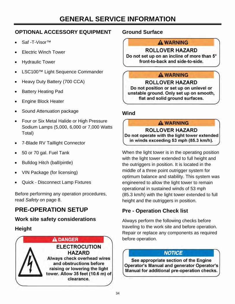
Height
Ground Surface
Wind
When the light tower is in the operating position with the light tower extended to full height and the outriggers in position. It is located in the middle of a three point outrigger system for optimum balance and stability. This system was engineered to allow the light tower to remain operational in sustained winds of 53 mph (85.3 km/h) with the light tower extended to full height and the outriggers in position.
Pre - Operation Check list
Always perform the following checks before traveling to the work site and before operation. Repair or replace any components as required before operation.
OPTIONAL ACCESSORY EQUIPMENT
Saf -T-Visor™
Electric Winch Tower
Hydraulic Tower
LSC100™ Light Sequence Commander
Heavy Duty Battery (700 CCA)
Battery Heating Pad
Engine Block Heater
Sound Attenuation package
Four or Six Metal Halide or High Pressure Sodium Lamps (5,000, 6,000 or 7,000 Watts Total)
7-Blade RV Taillight Connector
50 or 70 gal. Fuel Tank
Bulldog Hitch (ball/pintle)
VIN Package (for licensing)
Quick - Disconnect Lamp Fixtures
35
OPERATION
After completing the pre-operation check list, operate the light tower through a complete operation cycle.
Visually inspect the equipment to ensure that all instructions and decals are in place and legible.
Inspect the light tower locking bar latch assembly, which locks the light tower in the vertical position for proper operation. (Laydown Tower only).
Check the hitch assembly and safety chains.
Check the outriggers and jacks to make sure they operate properly.
Inspect the light assemblies for damage and test for proper operation.
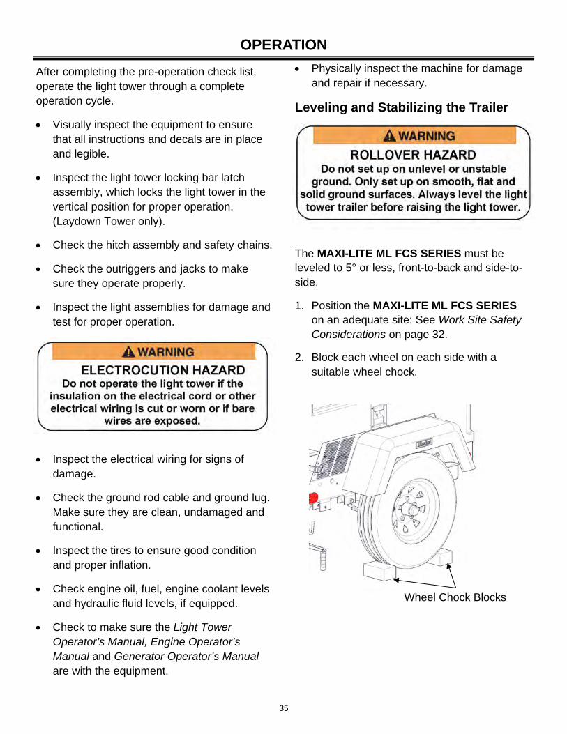
The MAXI-LITE ML FCS SERIES must be leveled to 5° or less, front-to-back and side-to-side.
1. Position the MAXI-LITE ML FCS SERIES on an adequate site: See Work Site Safety Considerations on page 32.
2. Block each wheel on each side with a suitable wheel chock.
Inspect the electrical wiring for signs of damage.
Check the ground rod cable and ground lug. Make sure they are clean, undamaged and functional.
Inspect the tires to ensure good condition and proper inflation.
Check engine oil, fuel, engine coolant levels and hydraulic fluid levels, if equipped.
Check to make sure the Light Tower Operator’s Manual, Engine Operator’s Manual and Generator Operator’s Manual are with the equipment.
Physically inspect the machine for damage and repair if necessary.
Leveling and Stabilizing the Trailer
Wheel Chock Blocks
36
OPERATION
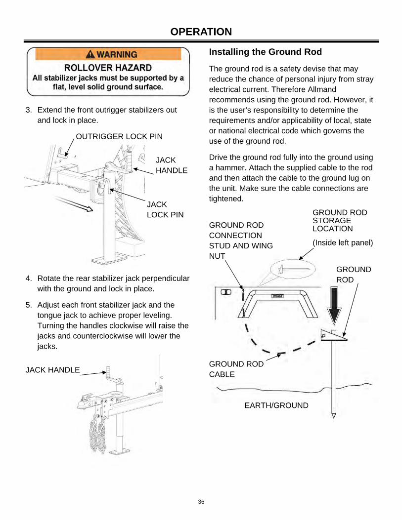
3. Extend the front outrigger stabilizers out and lock in place.
Installing the Ground Rod
The ground rod is a safety devise that may reduce the chance of personal injury from stray electrical current. Therefore Allmand recommends using the ground rod. However, it is the user’s responsibility to determine the requirements and/or applicability of local, state or national electrical code which governs the use of the ground rod.
Drive the ground rod fully into the ground using a hammer. Attach the supplied cable to the rod and then attach the cable to the ground lug on the unit. Make sure the cable connections are tightened.
OUTRIGGER LOCK PIN
JACK HANDLE
JACK LOCK PIN
4. Rotate the rear stabilizer jack perpendicular with the ground and lock in place.
5. Adjust each front stabilizer jack and the tongue jack to achieve proper leveling. Turning the handles clockwise will raise the jacks and counterclockwise will lower the jacks.
JACK HANDLE
GROUND ROD STORAGE LOCATION
(Inside left panel)
GROUND ROD CONNECTION STUD AND WING NUT
GROUND ROD CABLE
GROUND ROD
EARTH/GROUND
37
OPERATION
ENGINE OPERATION
Before starting the engine or operating the light tower, review Safety on page 8.
The Allmand MAXI-LITE ML FCS SERIES light tower is powered by a diesel engine and gen-erator unit.
Pre– Start Checks
1. Check the engine oil and add oil if required. Fill the engine with the proper grade of lubricating oil: refer to Engine Operator’s Manual for oil specifications.
2. Check and add diesel fuel as required.
3. Ensure that the air cleaner is firmly attached and air cleaner seals and hose clamps are properly sealed. Air cleaner element should be checked and replaced if necessary.
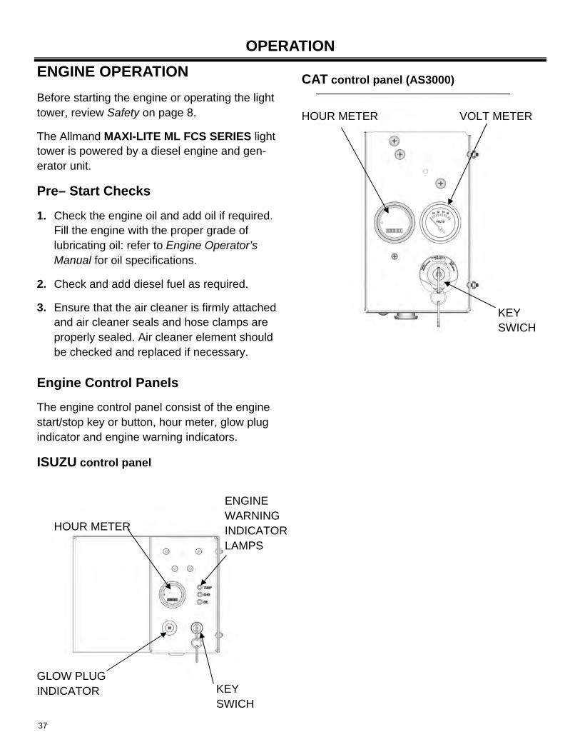
Engine Control Panels
The engine control panel consist of the engine start/stop key or button, hour meter, glow plug indicator and engine warning indicators.
ISUZU control panel
HOUR METER
GLOW PLUG INDICATOR
ENGINE WARNING INDICATOR LAMPS
KEY SWICH
CAT control panel (AS3000)
HOUR METER VOLT METER
KEY SWICH
38
OPERATION
1
2
1
2
3 4 5
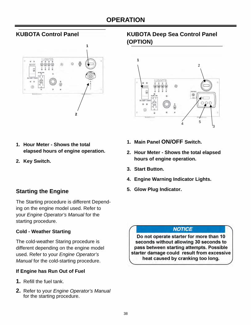
1. Hour Meter - Shows the total elapsed hours of engine operation.
2. Key Switch.
1. Main Panel ON/OFF Switch.
2. Hour Meter - Shows the total elapsed hours of engine operation.
3. Start Button.
4. Engine Warning Indicator Lights.
5. Glow Plug Indicator.
KUBOTA Control Panel KUBOTA Deep Sea Control Panel (OPTION)
Starting the Engine
The Starting procedure is different Depend-ing on the engine model used. Refer to your Engine Operator’s Manual for the starting procedure.
Cold - Weather Starting
The cold-weather Staring procedure is different depending on the engine model used. Refer to your Engine Operator’s Manual for the cold-starting procedure.
If Engine has Run Out of Fuel
1. Refill the fuel tank.
2. Refer to your Engine Operator’s Manual for the starting procedure.
39
OPERATION
Automatic Engine shutdown System
The engine is equipped with an automatic engine shutdown system to prevent excessive engine damage in the event of a low oil or overheat condition. For additional information, refer to your Engine Operator’s Manual.
Low Oil Pressure Shutoff
Should a low oil pressure condition occur, the oil pressure sending unit breaks the circuit between the circuit between the battery and the fuel solenoid, allowing the spring load to immediately move the fuel control to the shutoff position.
High Coolant Temperature Shutoff
Should a high coolant temperature condition occur, the temperature sending unit breaks the circuit between the battery and the fuel solenoid, allowing the spring load to immediately move the fuel control to the shutoff position.
TOWER AND LIGHT OPERATION
LAYDOWN
Before operating the tower lights, review Safety on page 8.
The laydown light tower is raised and lowered by a manual winch actuating a three section telescoping mast.
If starter is engaged while the flywheels rotating, the starter pinion and flywheel ring gear may clash, resulting in damage to the starter or flywheel ring gear.
Stopping the Engine
The engine stopping procedure may differ depending on the engine model. Refer to your Engine Operator’s Manual for engine stopping procedures.
TOWER AND LIGHT OPERATION
VERTICAL
Before operating the tower lights, review Safety on page 8.
The vertical tower is raised and lowered by a hydraulic pump actuating a six section telescoping mast.
40
OPERATION
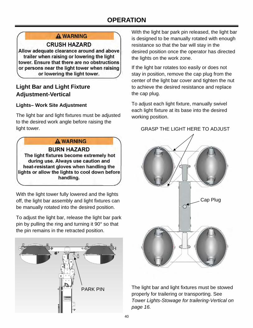
With the light bar park pin released, the light bar is designed to be manually rotated with enough resistance so that the bar will stay in the desired position once the operator has directed the lights on the work zone.
If the light bar rotates too easily or does not stay in position, remove the cap plug from the center of the light bar cover and tighten the nut to achieve the desired resistance and replace the cap plug.
To adjust each light fixture, manually swivel each light fixture at its base into the desired working position.
PARK PIN
Cap Plug
GRASP THE LIGHT HERE TO ADJUST
Light Bar and Light Fixture Adjustment-Vertical
Lights– Work Site Adjustment
The light bar and light fixtures must be adjusted to the desired work angle before raising the light tower.
With the light tower fully lowered and the lights off, the light bar assembly and light fixtures can be manually rotated into the desired position.
To adjust the light bar, release the light bar park pin by pulling the ring and turning it 90° so that the pin remains in the retracted position.
The light bar and light fixtures must be stowed properly for trailering or transporting. See Tower Lights-Stowage for trailering-Vertical on page 16.
41
OPERATION
The light bar and light fixtures must be stowed properly for trailering or transporting. See Tower Lights– Stowage for trailering-Laydown on page 17.
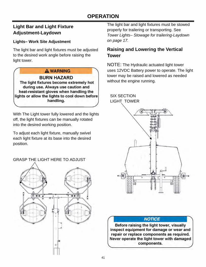
Raising and Lowering the Vertical Tower
NOTE: The Hydraulic actuated light tower uses 12VDC Battery power to operate. The light tower may be raised and lowered as needed without the engine running.
SIX SECTION LIGHT TOWER
Light Bar and Light Fixture Adjustment-Laydown
Lights– Work Site Adjustment
The light bar and light fixtures must be adjusted to the desired work angle before raising the light tower.
With The Light tower fully lowered and the lights off, the light fixtures can be manually rotated into the desired working position.
To adjust each light fixture, manually swivel each light fixture at its base into the desired position.
GRASP THE LIGHT HERE TO ADJUST
42
OPERATION
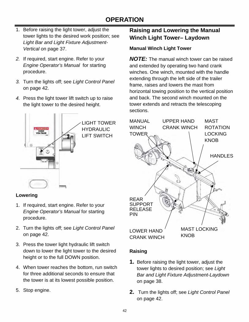
1. Before raising the light tower, adjust the tower lights to the desired work position; see Light Bar and Light Fixture Adjustment-Vertical on page 37.
2. If required, start engine. Refer to your Engine Operator’s Manual for starting procedure.
3. Turn the lights off; see Light Control Panel on page 42.
4. Press the light tower lift switch up to raise the light tower to the desired height.
Lowering
1. If required, start engine. Refer to your Engine Operator’s Manual for starting procedure.
2. Turn the lights off; see Light Control Panel on page 42.
3. Press the tower light hydraulic lift switch down to lower the light tower to the desired height or to the full DOWN position.
4. When tower reaches the bottom, run switch for three additional seconds to ensure that the tower is at its lowest possible position.
5. Stop engine.
LIGHT TOWER HYDRAULIC LIFT SWITCH
Raising and Lowering the Manual Winch Light Tower– Laydown
Manual Winch Light Tower
NOTE: The manual winch tower can be raised and extended by operating two hand crank winches. One winch, mounted with the handle extending through the left side of the trailer frame, raises and lowers the mast from horizontal towing position to the vertical position and back. The second winch mounted on the tower extends and retracts the telescoping sections.
MANUAL WINCH TOWER
REAR SUPPORT RELEASE PIN
LOWER HAND CRANK WINCH
UPPER HAND CRANK WINCH
MAST LOCKING KNOB
HANDLES
MAST ROTATION LOCKING KNOB
Raising
1. Before raising the light tower, adjust the tower lights to desired position; see Light Bar and Light Fixture Adjustment-Laydown on page 38.
2. Turn the lights off; see Light Control Panel on page 42.
43
OPERATION
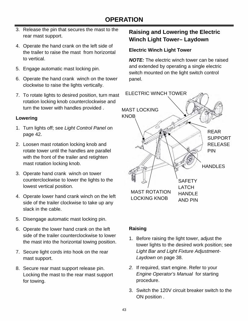
3. Release the pin that secures the mast to the rear mast support.
4. Operate the hand crank on the left side of the trailer to raise the mast from horizontal to vertical.
5. Engage automatic mast locking pin.
6. Operate the hand crank winch on the tower clockwise to raise the lights vertically.
7. To rotate lights to desired position, turn mast rotation locking knob counterclockwise and turn the tower with handles provided .
Lowering
1. Turn lights off; see Light Control Panel on page 42.
2. Loosen mast rotation locking knob and rotate tower until the handles are parallel with the front of the trailer and retighten mast rotation locking knob.
3. Operate hand crank winch on tower counterclockwise to lower the lights to the lowest vertical position.
4. Operate lower hand crank winch on the left side of the trailer clockwise to take up any slack in the cable.
5. Disengage automatic mast locking pin.
6. Operate the lower hand crank on the left side of the trailer counterclockwise to lower the mast into the horizontal towing position.
7. Secure light cords into hook on the rear mast support.
8. Secure rear mast support release pin. Locking the mast to the rear mast support for towing.
Raising and Lowering the Electric Winch Light Tower– Laydown
Electric Winch Light Tower
NOTE: The electric winch tower can be raised and extended by operating a single electric switch mounted on the light switch control panel.
ELECTRIC WINCH TOWER
REAR SUPPORT RELEASE PIN
MAST LOCKING KNOB
SAFETY LATCH HANDLE AND PIN
MAST ROTATION LOCKING KNOB
HANDLES
Raising
1. Before raising the light tower, adjust the tower lights to the desired work position; see Light Bar and Light Fixture Adjustment-Laydown on page 38.
2. If required, start engine. Refer to your Engine Operator’s Manual for starting procedure.
3. Switch the 120V circuit breaker switch to the ON position .
44
OPERATION
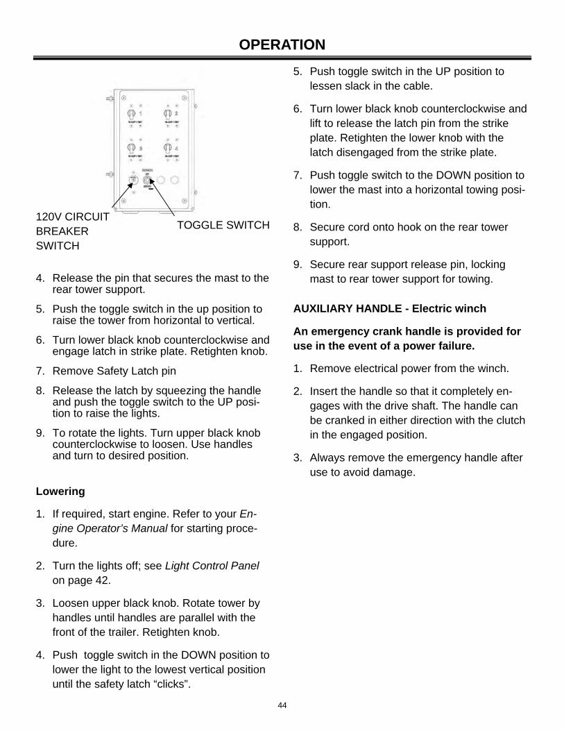
4. Release the pin that secures the mast to the rear tower support.
5. Push the toggle switch in the up position to raise the tower from horizontal to vertical.
6. Turn lower black knob counterclockwise and engage latch in strike plate. Retighten knob.
7. Remove Safety Latch pin
8. Release the latch by squeezing the handle and push the toggle switch to the UP posi-tion to raise the lights.
9. To rotate the lights. Turn upper black knob counterclockwise to loosen. Use handles and turn to desired position.
120V CIRCUIT BREAKER SWITCH
TOGGLE SWITCH
Lowering
1. If required, start engine. Refer to your En-gine Operator’s Manual for starting proce-dure.
2. Turn the lights off; see Light Control Panel on page 42.
3. Loosen upper black knob. Rotate tower by handles until handles are parallel with the front of the trailer. Retighten knob.
4. Push toggle switch in the DOWN position to lower the light to the lowest vertical position until the safety latch “clicks”.
5. Push toggle switch in the UP position to lessen slack in the cable.
6. Turn lower black knob counterclockwise and lift to release the latch pin from the strike plate. Retighten the lower knob with the latch disengaged from the strike plate.
7. Push toggle switch to the DOWN position to lower the mast into a horizontal towing posi-tion.
8. Secure cord onto hook on the rear tower support.
9. Secure rear support release pin, locking mast to rear tower support for towing.
AUXILIARY HANDLE - Electric winch
An emergency crank handle is provided for use in the event of a power failure.
1. Remove electrical power from the winch.
2. Insert the handle so that it completely en-gages with the drive shaft. The handle can be cranked in either direction with the clutch in the engaged position.
3. Always remove the emergency handle after use to avoid damage.
45
OPERATION
Turn on one, two, three or four light breaker switches to the ON position.
Lights Off
Turn all light breaker switches to the OFF position.
Lights On
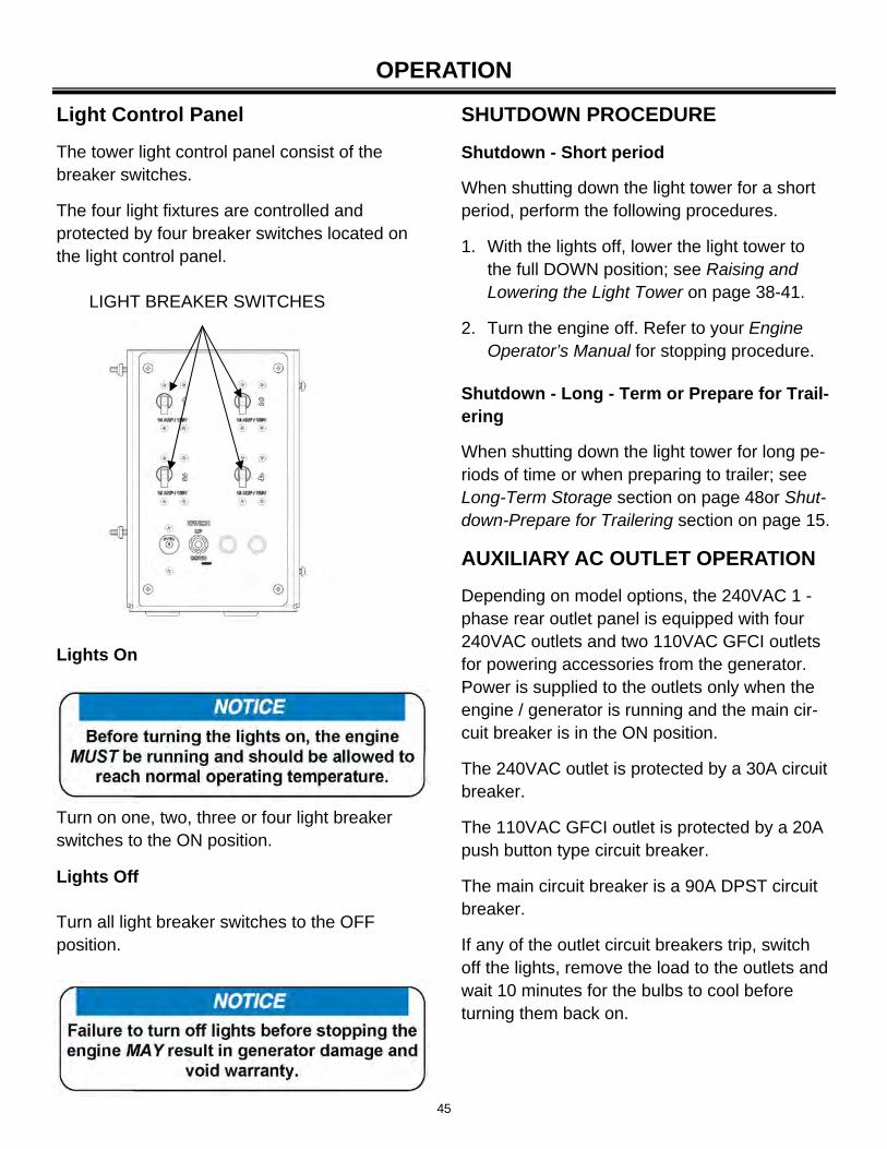
Light Control Panel
The tower light control panel consist of the breaker switches.
The four light fixtures are controlled and protected by four breaker switches located on the light control panel.
LIGHT BREAKER SWITCHES
SHUTDOWN PROCEDURE
Shutdown - Short period
When shutting down the light tower for a short period, perform the following procedures.
1. With the lights off, lower the light tower to the full DOWN position; see Raising and Lowering the Light Tower on page 38-41.
2. Turn the engine off. Refer to your Engine Operator’s Manual for stopping procedure.
Shutdown - Long - Term or Prepare for Trail-ering
When shutting down the light tower for long pe-riods of time or when preparing to trailer; see Long-Term Storage section on page 48or Shut-down-Prepare for Trailering section on page 15.
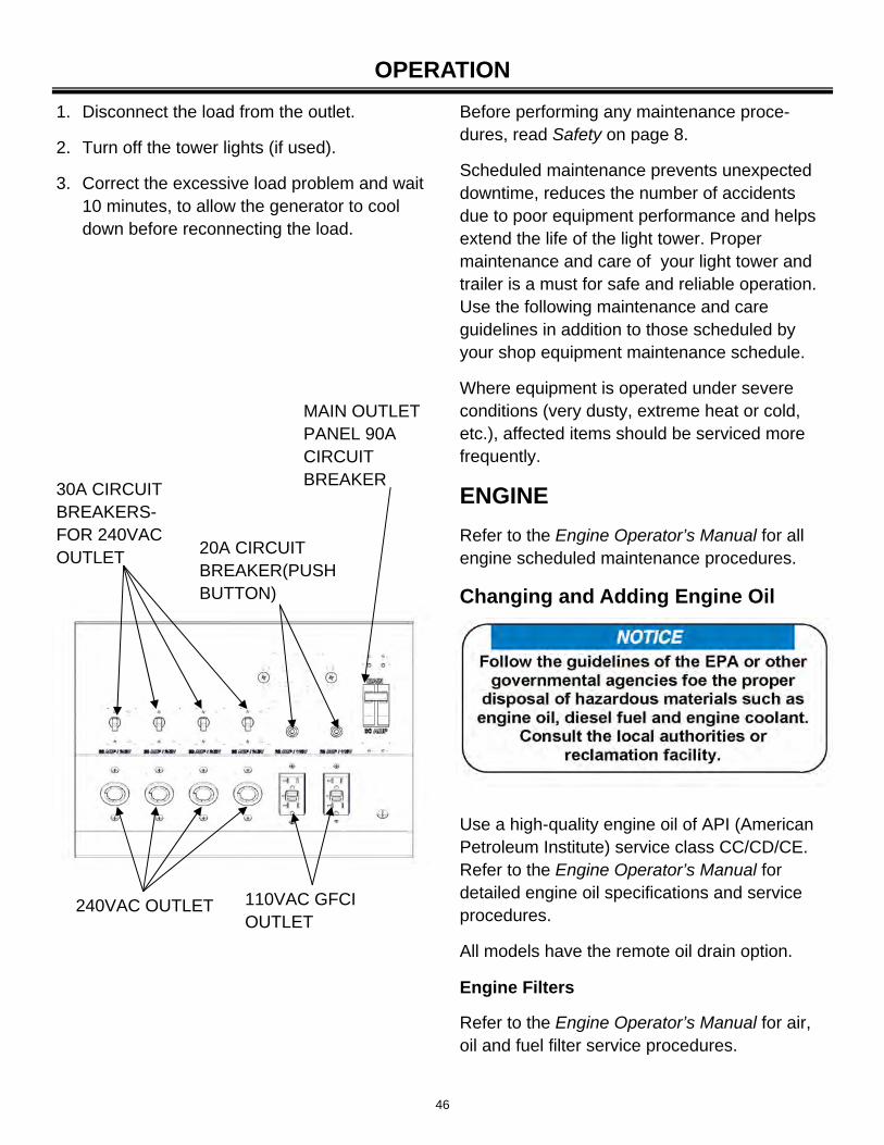
AUXILIARY AC OUTLET OPERATION
Depending on model options, the 240VAC 1 - phase rear outlet panel is equipped with four 240VAC outlets and two 110VAC GFCI outlets for powering accessories from the generator. Power is supplied to the outlets only when the engine / generator is running and the main cir-cuit breaker is in the ON position.
The 240VAC outlet is protected by a 30A circuit breaker.
The 110VAC GFCI outlet is protected by a 20A push button type circuit breaker.
The main circuit breaker is a 90A DPST circuit breaker.
If any of the outlet circuit breakers trip, switch off the lights, remove the load to the outlets and wait 10 minutes for the bulbs to cool before turning them back on.
46
Before performing any maintenance proce-dures, read Safety on page 8.
Scheduled maintenance prevents unexpected downtime, reduces the number of accidents due to poor equipment performance and helps extend the life of the light tower. Proper maintenance and care of your light tower and trailer is a must for safe and reliable operation. Use the following maintenance and care guidelines in addition to those scheduled by your shop equipment maintenance schedule.
Where equipment is operated under severe conditions (very dusty, extreme heat or cold, etc.), affected items should be serviced more frequently.
ENGINE
Refer to the Engine Operator’s Manual for all engine scheduled maintenance procedures.
Changing and Adding Engine Oil
Use a high-quality engine oil of API (American Petroleum Institute) service class CC/CD/CE. Refer to the Engine Operator’s Manual for detailed engine oil specifications and service procedures.
All models have the remote oil drain option.
Engine Filters
Refer to the Engine Operator’s Manual for air, oil and fuel filter service procedures.
OPERATION
MAIN OUTLET PANEL 90A CIRCUIT BREAKER
30A CIRCUIT BREAKERS-FOR 240VAC OUTLET
240VAC OUTLET 110VAC GFCI OUTLET
20A CIRCUIT BREAKER(PUSH BUTTON)
1. Disconnect the load from the outlet.
2. Turn off the tower lights (if used).
3. Correct the excessive load problem and wait 10 minutes, to allow the generator to cool down before reconnecting the load.
47
MAINTENANCE
ELECTRICAL SYSTEM
Refer to the Generator Operator’s Manual for all general scheduled maintenance procedures.
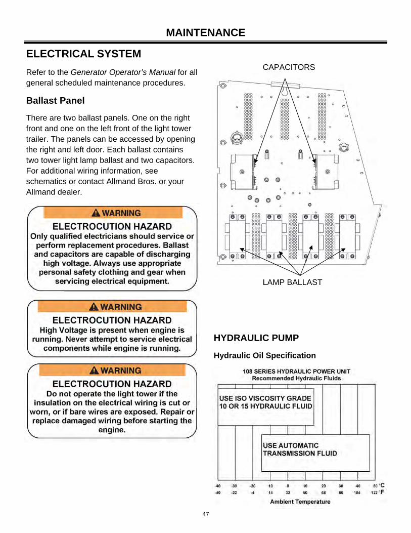
Ballast Panel
There are two ballast panels. One on the right front and one on the left front of the light tower trailer. The panels can be accessed by opening the right and left door. Each ballast contains two tower light lamp ballast and two capacitors. For additional wiring information, see schematics or contact Allmand Bros. or your Allmand dealer.
LAMP BALLAST
CAPACITORS
HYDRAULIC PUMP
Hydraulic Oil Specification
48
MAINTENANCE
Adding Hydraulic Oil
Fill the reservoir with aviation hydraulic fluid or any clean hydraulic fluid having a viscosity index that is suitable for the climate conditions in which the unit will be operated. Standard units are supplied with automatic transmission fluid (ATF), and arctic units are supplied with aviation hydraulic fluid.
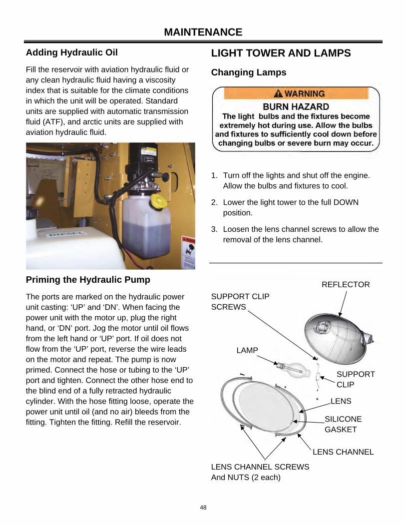
1. Turn off the lights and shut off the engine. Allow the bulbs and fixtures to cool.
2. Lower the light tower to the full DOWN position.
3. Loosen the lens channel screws to allow the removal of the lens channel.
SUPPORT CLIP SCREWS
SUPPORT CLIP
LAMP
REFLECTOR
LENS CHANNEL SCREWS And NUTS (2 each)
LENS CHANNEL
SILICONE GASKET
LENS
LIGHT TOWER AND LAMPS
Changing Lamps
Priming the Hydraulic Pump
The ports are marked on the hydraulic power unit casting: ‘UP’ and ‘DN’. When facing the power unit with the motor up, plug the right hand, or ‘DN’ port. Jog the motor until oil flows from the left hand or ‘UP’ port. If oil does not flow from the ‘UP’ port, reverse the wire leads on the motor and repeat. The pump is now primed. Connect the hose or tubing to the ‘UP’ port and tighten. Connect the other hose end to the blind end of a fully retracted hydraulic cylinder. With the hose fitting loose, operate the power unit until oil (and no air) bleeds from the fitting. Tighten the fitting. Refill the reservoir.
49
TRAILER
Proper maintenance and care of your trailer is a must for safe and reliable operation. Follow these maintenance and care guidelines in addition to those scheduled by your shop equipment maintenance schedule.
Frame
1. Check the coupler operation, and for corrosion or damage; replace as needed.
2. Inspect the lifting bar for corrosion or damage; replace as needed.
3. Inspect the trailer frame and body panels for rust, nicks and chips. Use the proper touch up paint to touch up nicks or scratches. Contact your dealer for additional information.
4. Inspect the axle, springs and undercarriage for wear and damage; replace as needed.
5. Inspect the outrigger bars, front and rear stabilizer jacks and locking mechanisms for proper operation, wear and damage; replace as needed.
4. Remove the silicone gasket and lens.
5. Remove the support clip screws and support clip.
6. Carefully remove the old lamp and install the correct replacement lamp.
7. Clean reflector and lens.
8. Install support clip and screws.
9. Install the silicone gasket and lens; replace if damaged or as needed.
10. Install lens channel and screws.
11. Test the new lamp to ensure proper operation.
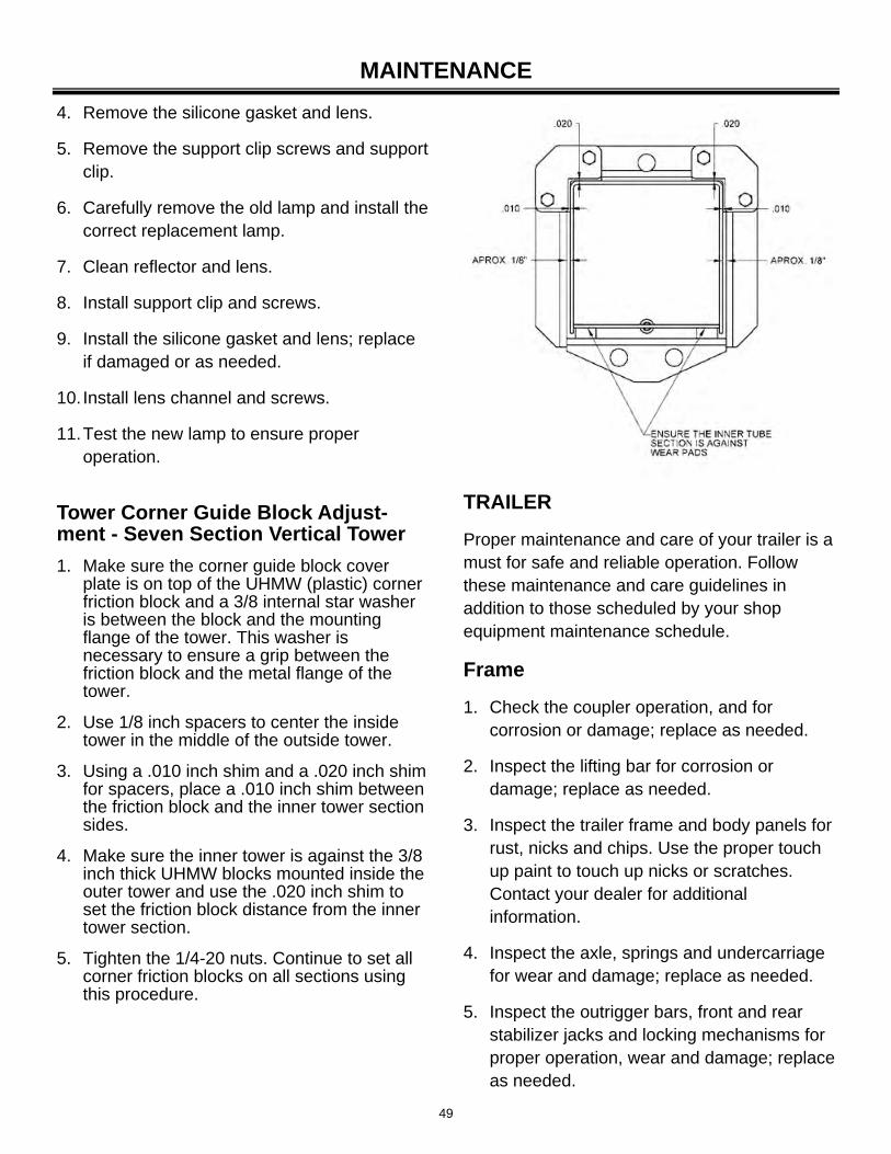
Tower Corner Guide Block Adjust-ment - Seven Section Vertical Tower
1. Make sure the corner guide block cover plate is on top of the UHMW (plastic) corner friction block and a 3/8 internal star washer is between the block and the mounting flange of the tower. This washer is necessary to ensure a grip between the friction block and the metal flange of the tower.
2. Use 1/8 inch spacers to center the inside tower in the middle of the outside tower.
3. Using a .010 inch shim and a .020 inch shim for spacers, place a .010 inch shim between the friction block and the inner tower section sides.
4. Make sure the inner tower is against the 3/8 inch thick UHMW blocks mounted inside the outer tower and use the .020 inch shim to set the friction block distance from the inner tower section.
5. Tighten the 1/4-20 nuts. Continue to set all corner friction blocks on all sections using this procedure.
MAINTENANCE
50
MAINTENANCE
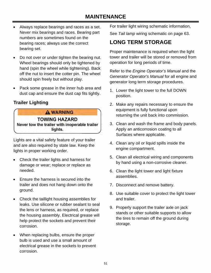
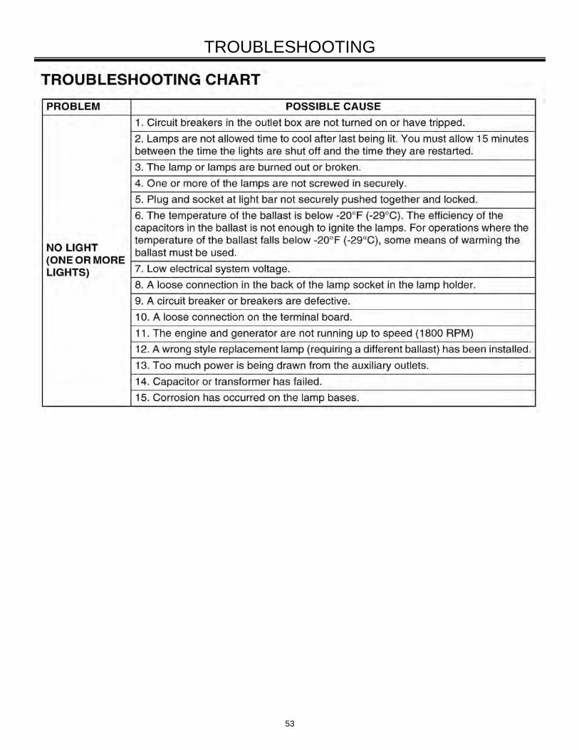
1. Check the tires for any cracks, cuts or damage. Repair or replace the damaged tires before towing.
2. Check the air pressure of the trailer tires when cold. The correct air pressure for the tire is specified on the tire. Never over or under inflate tires.
3. Check the wheel rims for any cracks or damage.
4. Make sure all the lug nuts are in place. Never tow the trailer with missing or improperly tightened lug nuts.
5. Check that the lug nuts are tightened properly. The correct torque for the lug nuts is 90 lb-ft (122N-m).
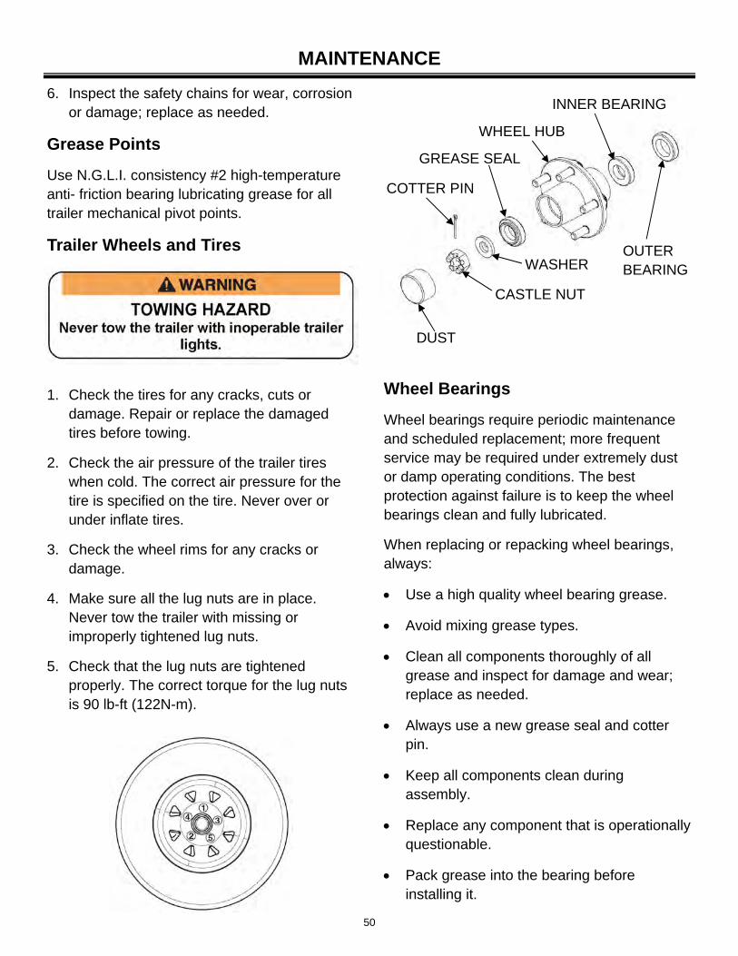
Wheel Bearings
Wheel bearings require periodic maintenance and scheduled replacement; more frequent service may be required under extremely dust or damp operating conditions. The best protection against failure is to keep the wheel bearings clean and fully lubricated.
When replacing or repacking wheel bearings, always:
Use a high quality wheel bearing grease.
Avoid mixing grease types.
Clean all components thoroughly of all grease and inspect for damage and wear; replace as needed.
Always use a new grease seal and cotter pin.
Keep all components clean during assembly.
Replace any component that is operationally questionable.
Pack grease into the bearing before installing it.
WHEEL HUB
INNER BEARING
OUTER BEARING
GREASE SEAL
COTTER PIN
WASHER
CASTLE NUT
DUST
6. Inspect the safety chains for wear, corrosion or damage; replace as needed.
Grease Points
Use N.G.L.I. consistency #2 high-temperature anti- friction bearing lubricating grease for all trailer mechanical pivot points.
Trailer Wheels and Tires
51
MAINTENANCE
Lights are a vital safety feature of your trailer and are also required by state law. Keep the lights in proper working order.
Check the trailer lights and harness for damage or wear; replace or replace as needed.
Ensure the harness is secured into the trailer and does not hang down onto the ground.
Check the taillight housing assemblies for leaks. Use silicone or rubber sealant to seal the lens or harness, as required, or replace the housing assembly. Electrical grease will help protect the sockets and prevent their corrosion.
When replacing bulbs, ensure the proper bulb is used and use a small amount of electrical grease in the sockets to prevent corrosion.
For trailer light wiring schematic information,
See Tail lamp wiring schematic on page 63.
LONG TERM STORAGE
Proper maintenance is required when the light tower and trailer will be stored or removed from operation for long periods of time.
Refer to the Engine Operator’s Manual and the Generator Operator’s Manual for all engine and generator long term storage procedures.
1. Lower the light tower to the full DOWN position.
2. Make any repairs necessary to ensure the equipment is fully functional upon returning the unit back into commission.
3. Clean and wash the frame and body panels. Apply an anticorrosion coating to all Surfaces where applicable.
4. Clean any oil or liquid spills inside the engine compartment.
5. Clean all electrical wiring and components by hand using a non-corrosive cleaner.
6. Clean the light tower and light fixture assemblies.
7. Disconnect and remove battery.
8. Use suitable cover to protect the light tower and trailer.
9. Properly support the trailer axle on jack stands or other suitable supports to allow the tires to remain off the ground during storage.
Always replace bearings and races as a set. Never mix bearings and races. Bearing part numbers are sometimes found on the bearing races; always use the correct bearing set.
Do not over or under tighten the bearing nut. Wheel bearings should only be tightened by hand (spin the wheel while tightening). Back off the nut to insert the cotter pin. The wheel should spin freely but without play.
Pack some grease in the inner hub area and dust cap and ensure the dust cap fits tightly.
Trailer Lighting
52
MAINTENANCE
CLEANING
Keeping the light tower clean is important to ensure proper operation. Dirt and dust buildup acts as an insulator and may cause the engine, generator and light assemblies to operate at excessively high temperatures.
Use the following guidelines:
Use caution when using compressed air or water/steam pressure washers. Do not pressure clean electrical components as this may damage electrical equipment.
Clean the light tower and remove all dust, dirt or other foreign material.
Inspect and clean the cooling air intake and exhaust louvers of the enclosure. Make sure they are clean. Remove dirt or any buildup that may restrict the cooling air flow.
Clean the light tower and its components with a damp cloth or sponge.
Inspect and clean all engine linkages so they operate properly.
Cleaning and Draining the Trailer Bilge
The Allmand MAXI-LITE FCS SERIES light towers have a fuel containment tray option, designed to catch fuel, oil or coolant spills. Should a spill occur, position a suitable container beneath the unit and remove the containment tray drain plug. After the fluid has been drained, reinstall the drain plug and dispose of the fluid properly in accordance with EPA or other governmental guidelines.
Before performing any troubleshooting procedures, read the following safety messages and read Safety on page 8.
For engine and generator troubleshooting, see the Engine Operator’s Manual and The Generator Operator’s Manual or contact Allmand Bros. Service Department or your Allmand dealer.
Always follow the electrical component manufacture specifications for voltage and test procedures.
53
TROUBLESHOOTING
54
MAINTENANCE RECORD DATE SERVICE DESCRIPTION SERVICED BY

55
SCHEMATIC ISUZU 4LE1 ENGINE
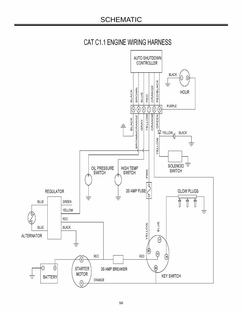
56
SCHEMATIC
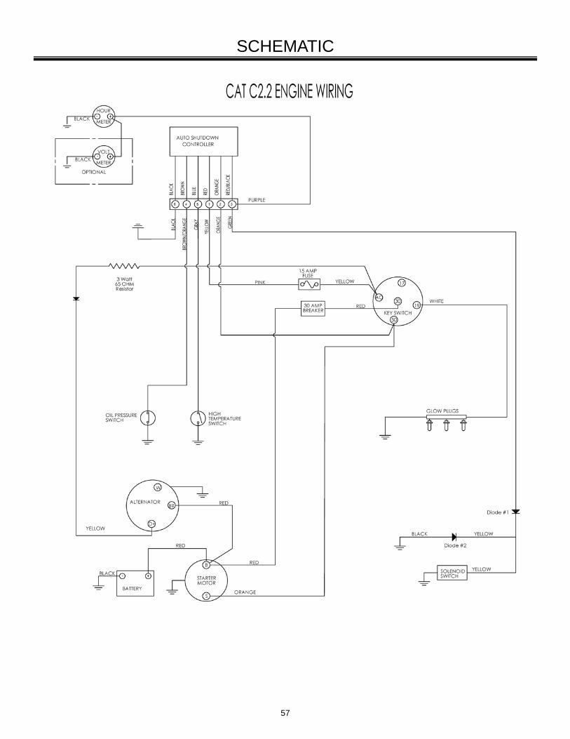
57
SCHEMATIC
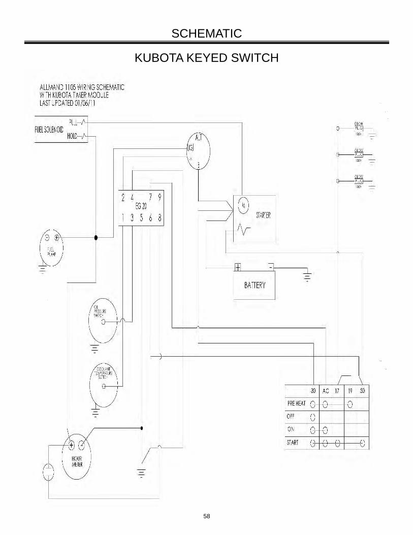
58
KUBOTA KEYED SWITCH
SCHEMATIC
59
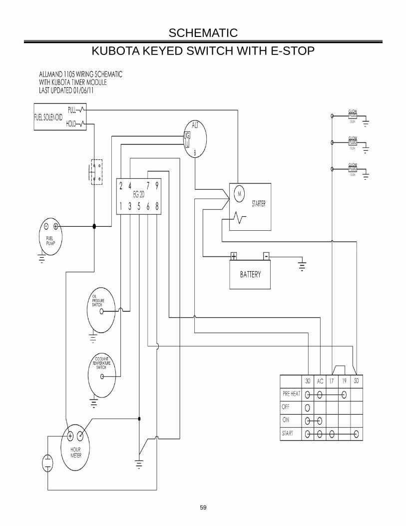
KUBOTA KEYED SWITCH WITH E-STOP
SCHEMATIC
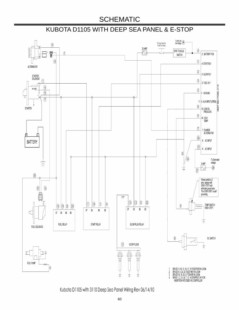
60
KUBOTA D1105 WITH DEEP SEA PANEL & E-STOP
SCHEMATIC
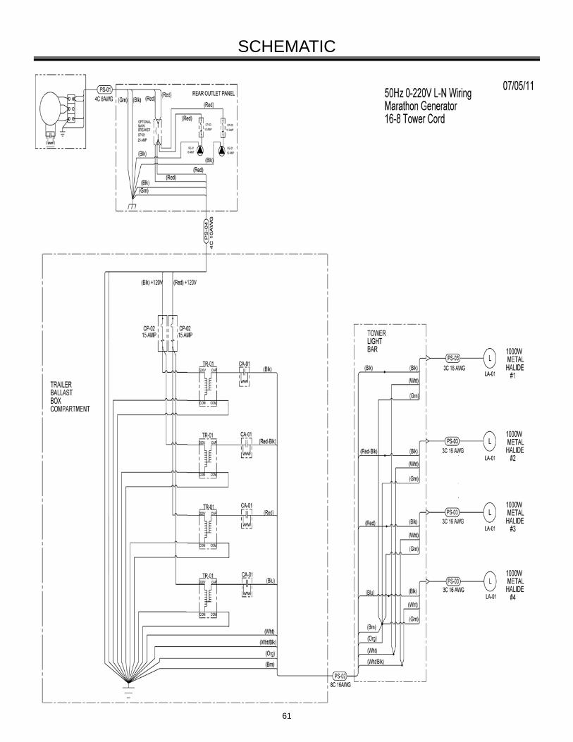
61
SCHEMATIC
62
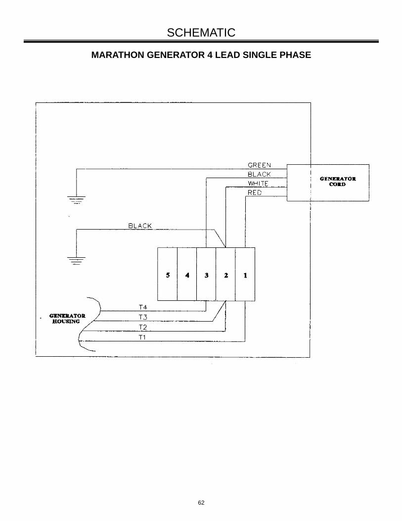
SCHEMATIC
MARATHON GENERATOR 4 LEAD SINGLE PHASE
63
SCHEMATIC
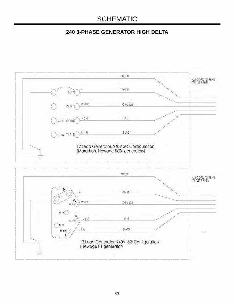
240 3-PHASE GENERATOR HIGH DELTA
64
SCHEMATIC
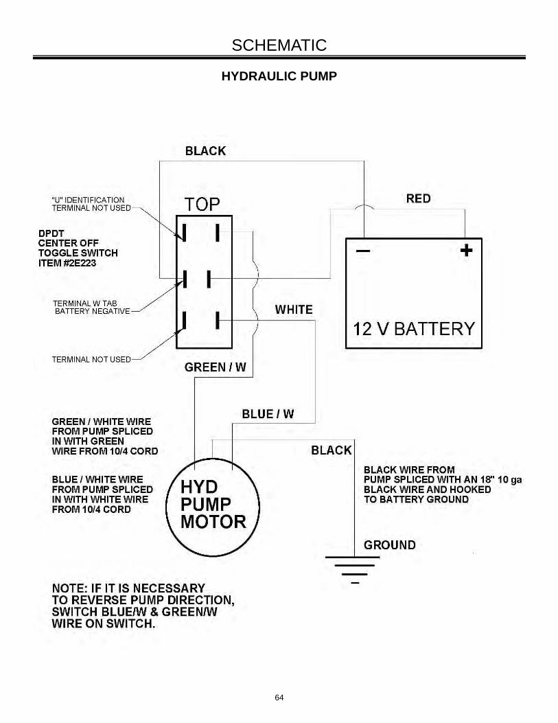
HYDRAULIC PUMP
65
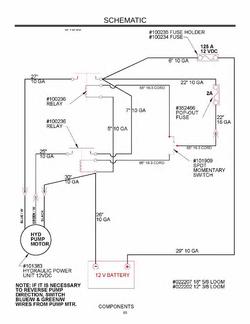
SCHEMATIC
66
SCHEMATIC
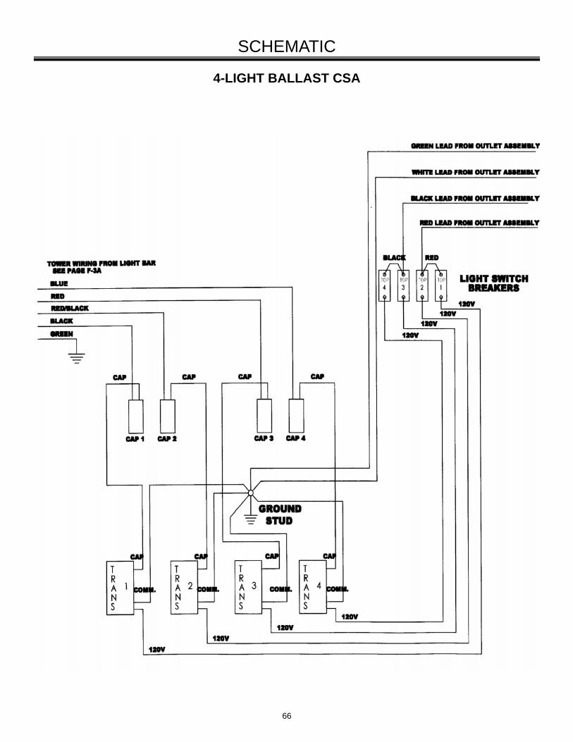
4-LIGHT BALLAST CSA
67
TAILLIGHT WIRING SCHEMATIC
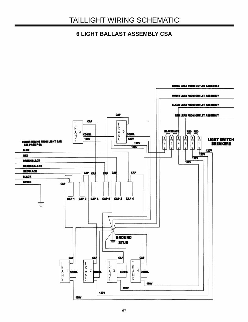
6 LIGHT BALLAST ASSEMBLY CSA
68
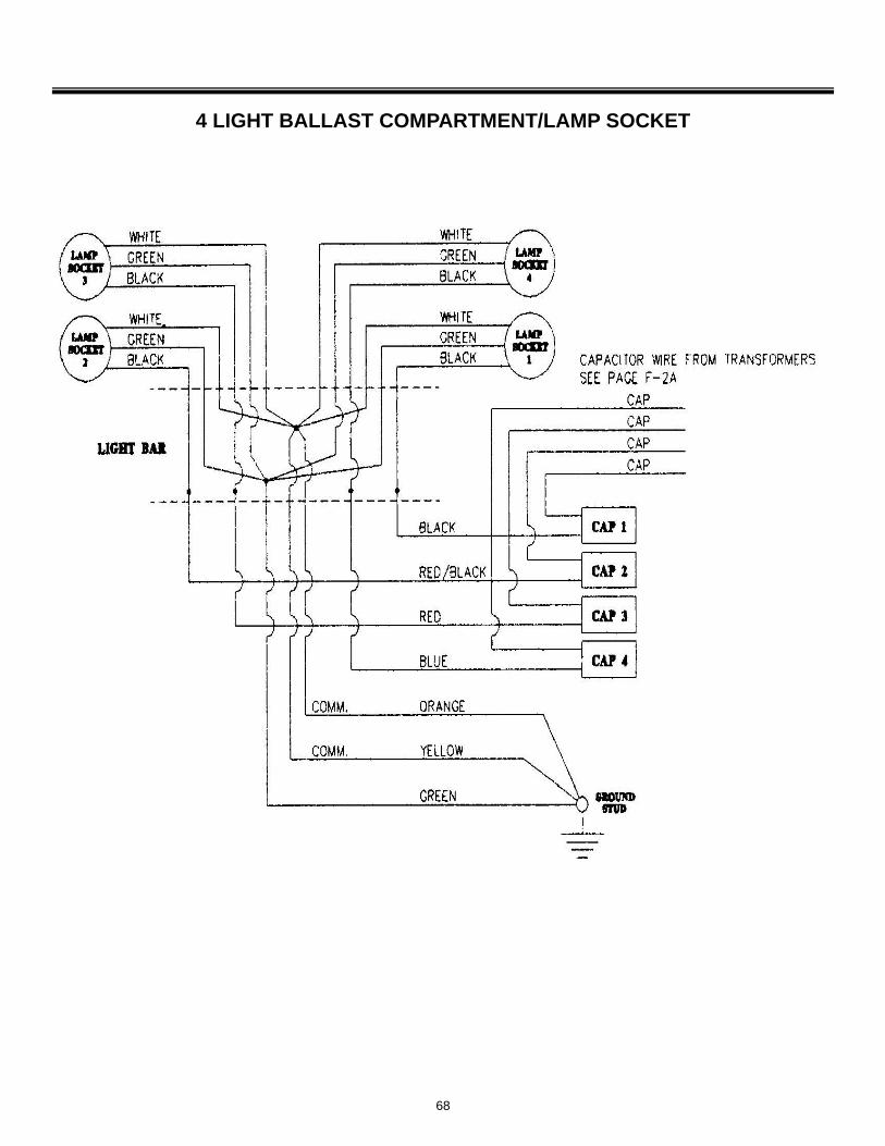
4 LIGHT BALLAST COMPARTMENT/LAMP SOCKET
69
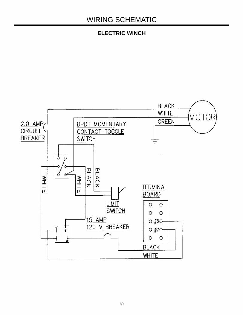
ELECTRIC WINCH
WIRING SCHEMATIC
70
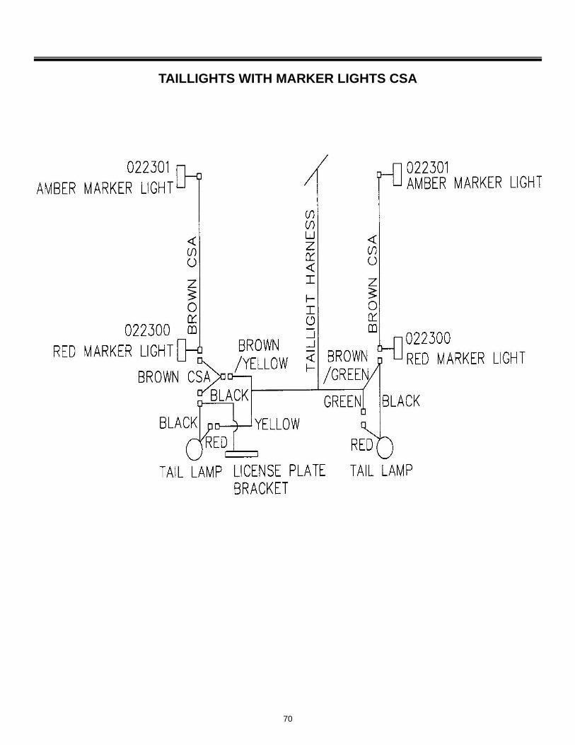
TAILLIGHTS WITH MARKER LIGHTS CSA
71
240V 3 PHASE ELECTRIC WINCH 4 LIGHT
SCHEMATIC
72
240V 3 PHASE ELECTRIC WINCH 6 LIGHT BALLAST PANEL
WIRING SCHEMATIC
73
240V REAR OUTLET PANEL SINGLE PHASE
WIRING SCHEMATIC
74
240V 3 PHASE ELECTRIC WINCH 6 LIGHT LIGHT BAR
WIRING SCHEMATIC
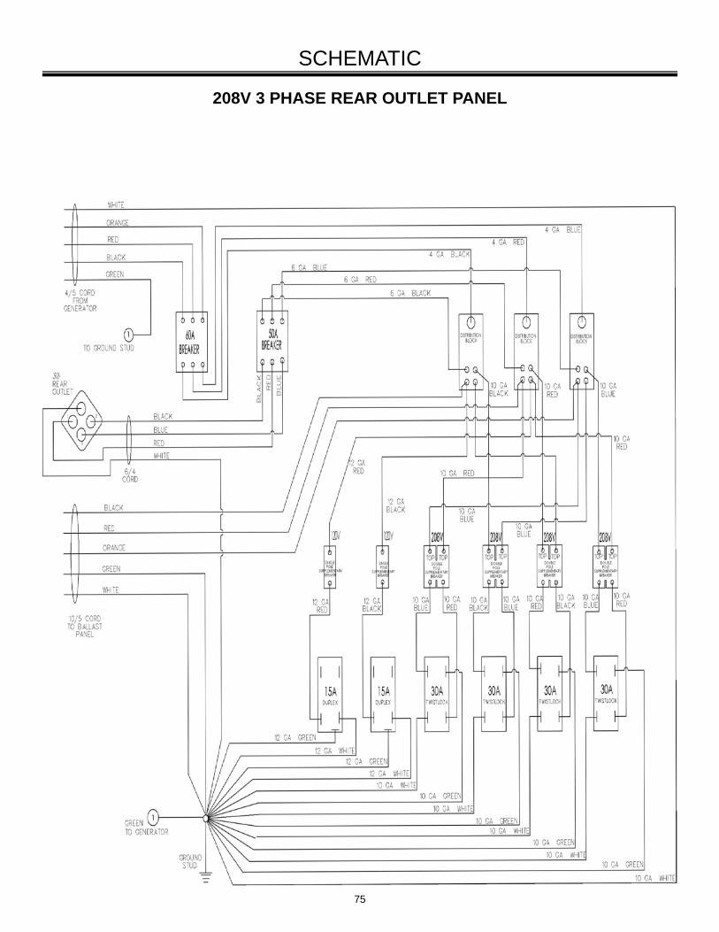
75
SCHEMATIC
208V 3 PHASE REAR OUTLET PANEL
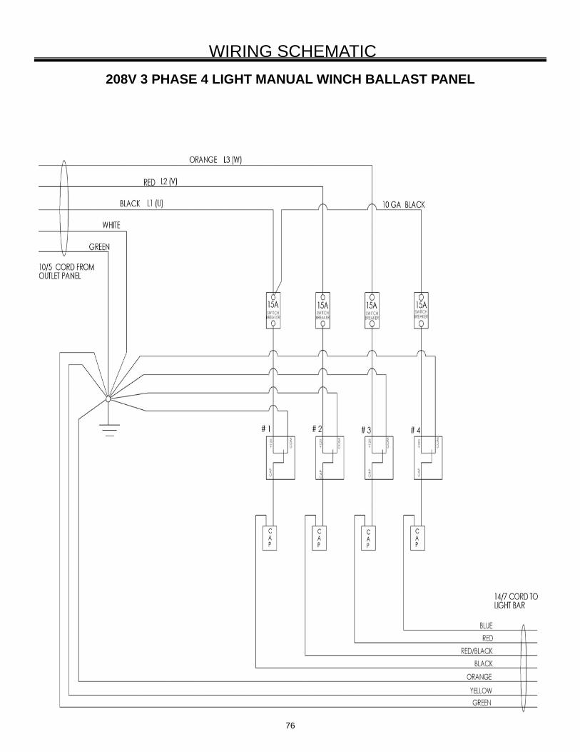
76
208V 3 PHASE 4 LIGHT MANUAL WINCH BALLAST PANEL
WIRING SCHEMATIC
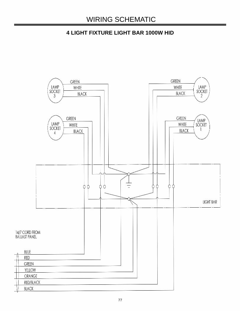
77
4 LIGHT FIXTURE LIGHT BAR 1000W HID
WIRING SCHEMATIC

78
208V 3 PHASE 6 LIGHT MANUAL WINCH BALLAST PANEL
WIRING SCHEMATIC
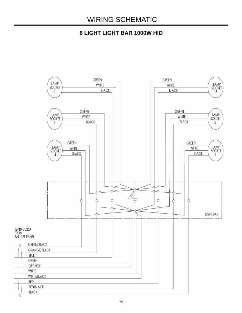
79
6 LIGHT LIGHT BAR 1000W HID
WIRING SCHEMATIC
80
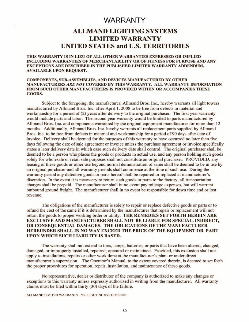
WARRANTY
Limited Warranty LIGHTING SYSTEMS Addendum 11/12
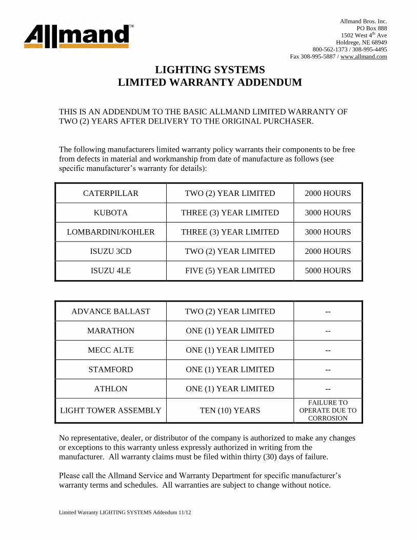
LIGHTING SYSTEMS
LIMITED WARRANTY ADDENDUM
THIS IS AN ADDENDUM TO THE BASIC ALLMAND LIMITED WARRANTY OF
TWO (2) YEARS AFTER DELIVERY TO THE ORIGINAL PURCHASER.
The following manufacturers limited warranty policy warrants their components to be free
from defects in material and workmanship from date of manufacture as follows (see
specific manufacturer’s warranty for details):
CATERPILLAR TWO (2) YEAR LIMITED 2000 HOURS
KUBOTA THREE (3) YEAR LIMITED 3000 HOURS
LOMBARDINI/KOHLER THREE (3) YEAR LIMITED 3000 HOURS
ISUZU 3CD TWO (2) YEAR LIMITED 2000 HOURS
ISUZU 4LE FIVE (5) YEAR LIMITED 5000 HOURS
ADVANCE BALLAST TWO (2) YEAR LIMITED --
MARATHON ONE (1) YEAR LIMITED --
MECC ALTE ONE (1) YEAR LIMITED --
STAMFORD ONE (1) YEAR LIMITED --
ATHLON ONE (1) YEAR LIMITED --
LIGHT TOWER ASSEMBLY TEN (10) YEARS FAILURE TO
OPERATE DUE TO
CORROSION
No representative, dealer, or distributor of the company is authorized to make any changes
or exceptions to this warranty unless expressly authorized in writing from the
manufacturer. All warranty claims must be filed within thirty (30) days of failure.
Please call the Allmand Service and Warranty Department for specific manufacturer’s
warranty terms and schedules. All warranties are subject to change without notice.
Allmand Bros. Inc.
PO Box 888
1502 West 4th Ave
Holdrege, NE 68949
800-562-1373 / 308-995-4495
Fax 308-995-5887 / www.allmand.com