maximum power point tracker for solar...
TRANSCRIPT
MAXIMUM POWER POINT TRACKER FOR SOLAR CHARGE CONTROLLER APPLICATIONS
STUDENT: GITONGA M. JAMES
REG. NO. F17/2123/2004
SUPERVISOR: MR. C. OMBURA
EXAMINER: MR. DHARMADHIKARY
PRJ. NO. 64
2009

OUTLINE
• PROJECT OBJECTIVES• INTRODUCTION• METHODOLOGY• PROCEDURE• RESULTS• DISCUSSION• CONCLUSION• QUESTIONS

PROJECT OBJECTIVES
• To design a High efficient Maximum Power Point Tracker
• To Implement the design • Test the working of the Design

INTRODUCTION
• Solar energy is a clean, free and renewablenatural resource offering environmentalfriendly source of electricity.
• Conversion from solar to electrical energy isachieved by photovoltaic (PV) arrays.
• Since PV arrays are relatively expensive, it isdesired to extract maximum power fromthem at any given time.
Introduction (cont.)
• Maximum Power Point Tracking (MPPT):
– Technique used in power electronics systems toobtain the maximum possible energy fromenergy such as solar, wind and tidal..
– Its use is desired to compensate for the effect oftemperature, ageing, variations in solar radiation(insolation), and load condition in a PV system.
• Implemented using simple and analogmethod - Ripple Correlation Control andFixed reference voltage Method.

METHODOLOGY• To achieve the MPPT:
– Characterization of solar panels.
– Development of a mathematical relation to control the output Voltage of a buck converter.
– System modelling using Multisim 10.0 and Proteous 7.0 Professional.
– Practical implementation of the system.

Methodology (cont.)
Block diagram of the MPPT system:
Solar Solar PanelsPanels
Buck Buck ConverterConverter BatteryBattery
SensorsSensors(V & I)(V & I)
Control Control LawLaw PWM PWM
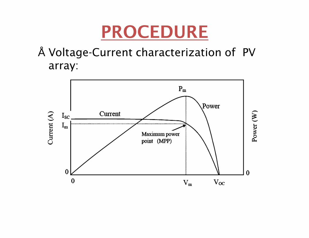
PROCEDURE• Voltage-Current characterization of PV
array:
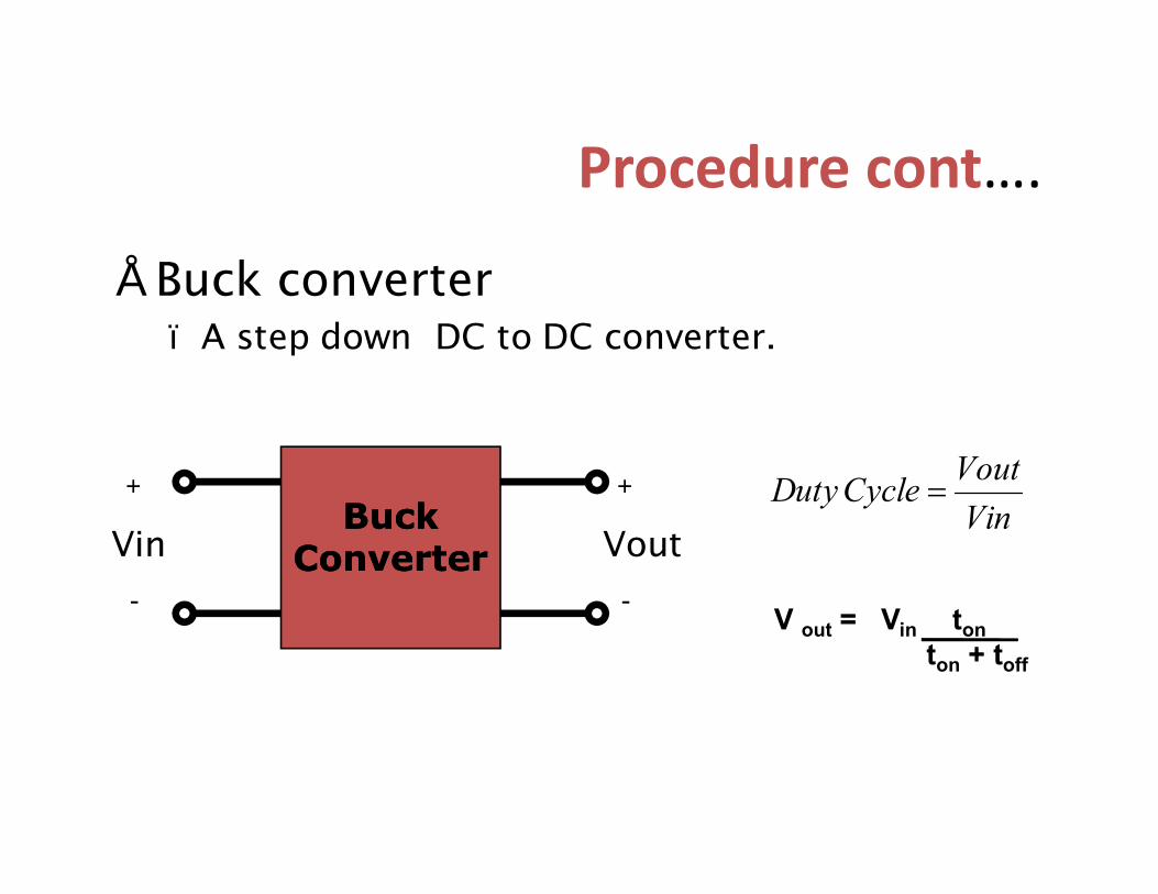
Procedure cont….
• Buck converter– A step down DC to DC converter.
VinVoutCycleDuty =
Buck Buck ConverterConverter
+
Vin
-
+
Vout
- V out = Vin tonton + toff

Procedure cont….Circuitry Implementation of a buck Converter
L = C =

Tabulation of Array voltage and subsequent Duty cycle and control voltage required for Fixed reference voltage law derivation
PV array VoltageRequired Duty Cycle
Required Control Voltage
14 1 514.74 0.95 5.2515.55 0.90 5.516.47 0.85 5.7517.5 0.80 618.7 0.75 6.2520 0.70 6.521.54 0.65 6.7523.4 0.60 725.45 0.55 7.25
Procedure Cont…..

Procedure Cont…• Control law relates Control Voltage Panel Voltage
• Obtained using a linear approximation
0
1
2
3
4
5
6
7
8
0 5 10 15 20 25 30
Control Voltage(Vc)
PV Voltage (Vpv)
Required Control voltage Versus PV. Voltage
Ideal
Linearized
Linearized equation Vc = 2.5 + 0.2Vpv

Procedure Cont…
V =15V
• Fixed reference voltage law derivation Circuit implementation

Photovoltaic Array Characteristics
Array Voltage Array Current(mA) Power(mW)8.35 0.4 3.348.32 0.9 7.4888.29 1.5 12.4358.23 3 24.698.16 5.8 47.3288.02 10.4 83.4087.77 21.5 167.0556.64 48.3 320.7125.3 62.5 331.25
2.35 73.6 172.960.68 78.1 53.1080.2 80 16
Photovoltaic Array characterization For ripple Correlation Control law derivation
Procedure Cont…
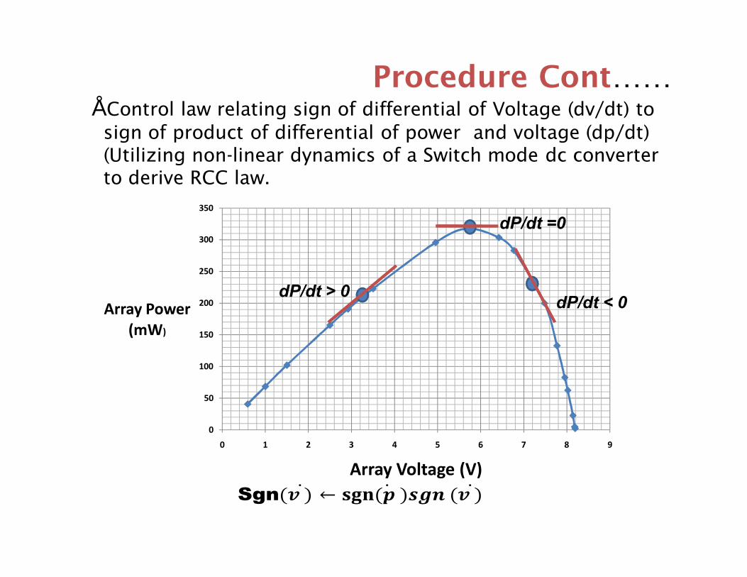
Procedure Cont……
0
50
100
150
200
250
300
350
0 1 2 3 4 5 6 7 8 9
Array Power (mW)
Array Voltage (V)
dP/dt > 0
dP/dt =0
dP/dt < 0
• Control law relating sign of differential of Voltage (dv/dt) to sign of product of differential of power and voltage (dp/dt) (Utilizing non-linear dynamics of a Switch mode dc converter to derive RCC law.
Sgn

Ripple correlation Control method circuitry implementation
(dv/dt)
dp/dt
Procedure Cont……
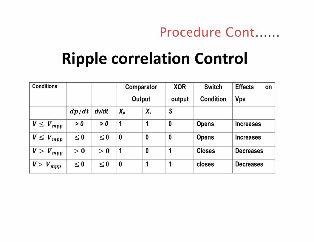
Ripple correlation ControlConditions Comparator
Output XOR
output Switch
Condition Effects on Vpv
dv/dt Xp Xv S
V > 0 > 0 1 1 0 Opens Increases
V 0 0 0 0 0 Opens Increases
V 1 0 1 Closes Decreases
V 0 0 0 1 1 closes Decreases
Procedure Cont……

Procedure (cont.)
• Important Sections in the control unit (MPPT):– Current sensor: I to V Converter– Voltage sensor – Control circuit - circuit implementation of the
control law– Pulse Width Modulator (PWM)- adjusts the
duty cycle– Square wave generator– Sawtooth Wave Generator
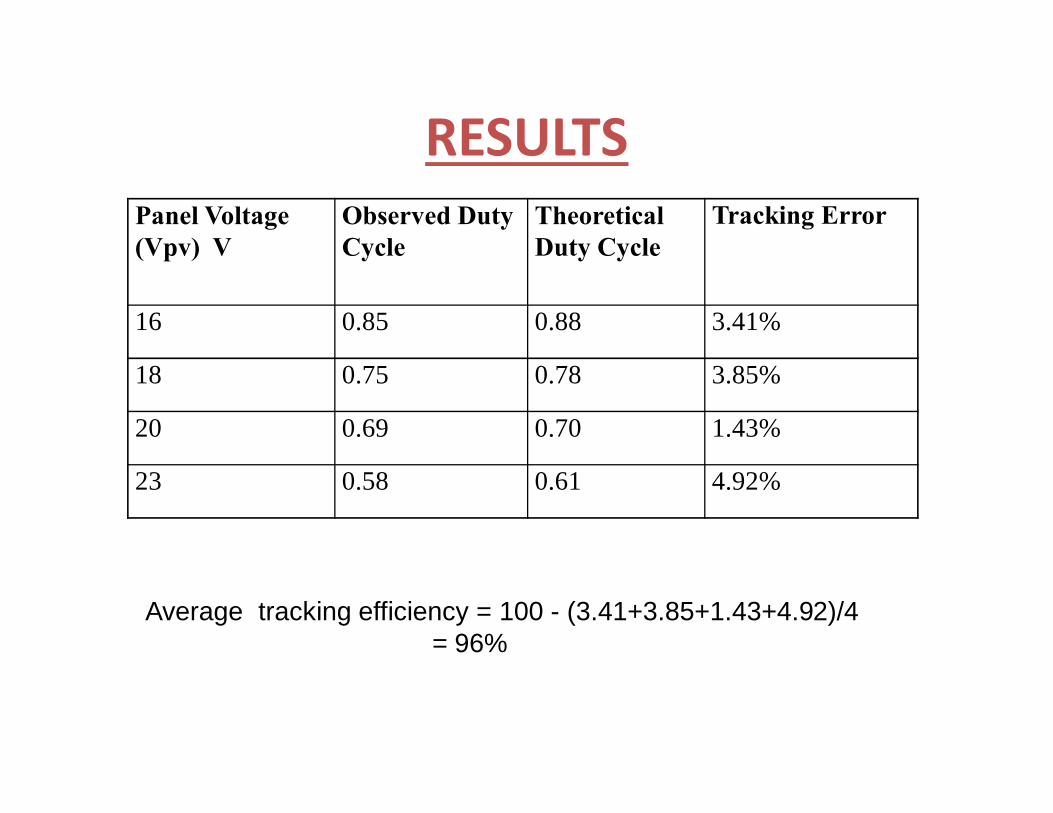
RESULTSPanel Voltage (Vpv) V
Observed Duty Cycle
Theoretical Duty Cycle
Tracking Error
16 0.85 0.88 3.41%
18 0.75 0.78 3.85%
20 0.69 0.70 1.43%
23 0.58 0.61 4.92%
Average tracking efficiency = 100 - (3.41+3.85+1.43+4.92)/4= 96%
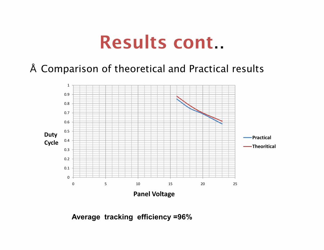
Results cont..• Comparison of theoretical and Practical results
0
0.1
0.2
0.3
0.4
0.5
0.6
0.7
0.8
0.9
1
0 5 10 15 20 25
DutyCycle
Panel Voltage
Practical
Theoritical
Average tracking efficiency =96%

DISCUSSION
• Maximum power points obtained using the control law were very close to theoretical values.
• Results obtained from the tests were as expected.
• The designed MPPT is not dependent on the converter used, making it flexible and adaptable to other dc-dc switching topologies.
• Divergence occurred for higher values of insolation and Low insolation levels.

CONCLUSIONS
• System is able to track maximum power at different insolation levels.
• Variations between theoretical and experimental data is due to:– Linear approximation of duty cycle
• Validation of the control laws through a simple and analog MPPT.

RECOMMENDATIONS
• Implementation of the designed MPPT using Microcontrollers
• Research on integrating the MPPT discussed in this paper with Wind power
• Research on ways of integrating the designed MPPT to dynamic systems such as solar powered vehicles.

Prototype of the Designed Maximum Power Point Tracker

Questions

Testing of the designed MPPT

Square Wave generator
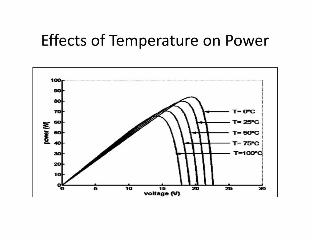
Effects of Temperature on Power
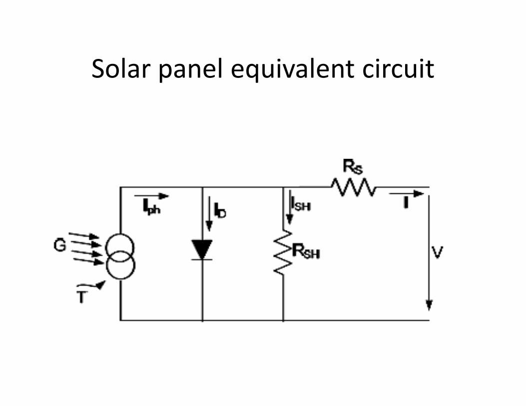
Solar panel equivalent circuit

Block of Fixed Reference Voltage Method

Current Sensor
-Vpv

Analog Multiplier
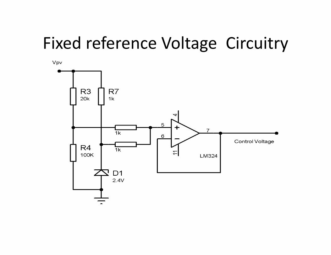
Fixed reference Voltage Circuitry

Voltage Sensor

Differentiator

Complete Circuit Diagram

Observed waveform
• Vpv =18 volts, duty cycle =0.75 (theoretical0.78)
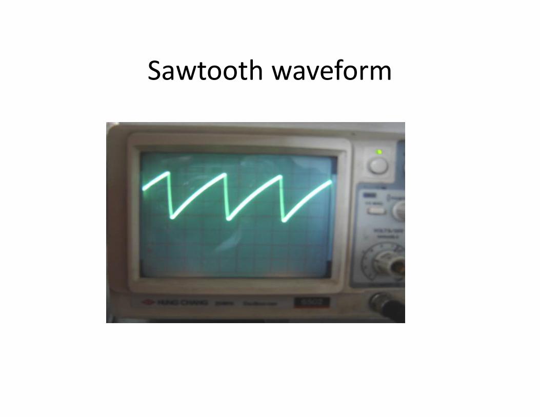
Sawtooth waveform