maximum resonance and cancellation phenomena in
TRANSCRIPT

Maximum resonance and cancellation phenomena in orthotropic platestraversed by moving loads: application to railway bridges
M.D. Martınez-Rodrigoa,∗, E. Molinera, A. Romerob, G. De Roeckc, P. Galvınb
aUniversitat Jaume I, Department of Mechanical Engineering and Construction, Avda. Sos Baynat s/n, ES-12071Castellon, Spain
bEscuela Tecnica Superior de Ingenierıa, Universidad de Sevilla, Camino de los Descubrimientos s/n, ES-41092 Sevilla,Spain
cDepartment of Civil Engineering, K.U.Leuven, Kasteelpark Arenberg 40, B-3001 Leuven, Belgium
Abstract
The vibrational response of railway bridges is an issue of main concern, especially since the advent of
High-Speed traffic. In the case of short-to-medium lengths and simply-supported spans excessive transverse
acceleration levels may be induced at the platform, with detrimental consequences for passengers and infras-
tructures. The orthotropic plate has proven to be an appropriate model for the prediction of the response
of certain typologies in the aforementioned cases such as multiple girder decks, solid or voided slabs or
filler-beam multiple-track decks. In this contribution, the vibrational response of orthotropic plates, simply
and elastically supported, circulated by vertical moving loads is investigated. First, maximum free vibration
and cancellation conditions are derived analytically. From these, bridge span length-characteristic distance
ratios leading to maximum and minimum resonances under series of equidistant loads are depicted. Second,
the applicability of these ratios in oblique decks is analysed for the most common first three mode shapes:
first longitudinal bending, first torsion and first transverse bending modes, and the errors in relation to
the straight reference case are bounded. To this end, an extensive bridge catalogue of girder bridges is
designed in the range of lengths of interest, covering flexural stiffnesses typical from both conventional and
High-Speed railway lines. Finally, the applicability of the previous theoretical results is exemplified with
experimental measurements performed on a bridge from the Spanish railway network.
Keywords: Railway bridges, orthotropic plates, resonance, cancellation, moving loads.
1. Introduction
Since the opening of the first High-Speed (HS) railway line in the 1960s in Japan, railway infrastructures
have evolved dramatically in most developed countries. During the last decades, several HS lines have been
constructed and many conventional lines have been upgraded to higher operating speeds. Spain is one of
∗Corresponding author.Email address: [email protected] (M.D. Martınez-Rodrigo)
Preprint submitted to International Journal of Mechanical Sciences November 13, 2019

the leading countries in this regard with almost 2600 km of operational HS lines [1]. The increase of the5
design speeds brings along difficulties and new challenges. In particular, railway bridges must accomplish
now strict requirements in terms of maximum vibration levels for the sake of passenger comfort and traffic
safety. In this context, the dynamic behaviour of such structures has received considerable attention from
the engineering and scientific community in the past decades.
This investigation focuses on the particular case of short-to-medium length (10−25 m) simply-supported10
(SS) bridges, which are prone to experience high transverse acceleration levels at the platform due to their
usually associated low mass and structural damping [2, 3, 4, 5]. In countries like Spain in the aforementioned
range of lengths common deck typologies built in the 80’s and 90’s for double track platforms are voided or
solid concrete slabs, pseudo-slabs and precast decks composed by double-T beams [6] (see Fig. 1). In the last
years, twin cell box girder decks are becoming more common due to their enhanced dynamic performance.15
With the exception of the lastest, the vertical dynamic response of the aformentioned structures may be
adequately predicted with orthotropic plate models, showing good correspondence with experimental mea-
surements [7]. For this reason, the response of orthotropic plates under moving loads and its application to
railway bridges constitutes the main interest of this work.
Figure 1: Railway bridge decks common for short-to-intermediate lengths: (a) precast double-T girder deck; (b) concrete
pseudo-slab; (c) concrete solid slab; (d) concrete voided slab.
The basic phenomenon that governs the level of vibrations induced on a bridge by the circulation of a20
railway convoy is the amplitude of the free vibrations that a single axle leaves on the structure after its
passage. Depending on the ratio between the travelling time of the load crossing the bridge and a certain
natural period of the structure, the amplification of the free vibration response in that particular mode may
be maximum or may be theoretically cancelled, implying that the structure would remain at rest under
certain ideal conditions (i.e. in the absence of structural damping). This basic problem has been analysed25
in detail by authors such as Yang et al. [8], Savin [9] and Museros et al. [10] for SS beams and also
for beams resting on vertical elastic supports (ES beams in what follows). The aim and novelty of this
2

investigation is to extend this study and evaluate its validity to orthotropic plates representative of bridges
with a dynamic behaviour characterized by modal contributions different from the longitudinal bending
ones (i.e. first torsion, first transverse bending modes). This is the case of SS multiple track decks with30
length to width ratios close to unity and sections similar to those included in Figs. 1(a-d). In general, these
structures exhibit several natural modes below 30 Hz which may significantly contribute to the maximum
vertical acceleration [7].
The interest of knowing a priori the maximum free vibration and cancellation speeds for a certain
structure is diverse. First, if a train induces resonance on a bridge, the dynamic amplification will depend35
on the closeness of the resonant velocity to these maximum free vibration or cancellation conditions. If the
resonant speed coincides with a maximum free vibration condition, important amplification levels should be
expected. On the contrary, if it takes place in the vicinity of a cancellation speed, the resonant peak will
become imperceptible. Even though it is well known that in a real situation resonant amplitudes depend on
several factors, e.g. number of convoys, vehicle-structure and soil-structure interaction, and other damping40
and amplitude dependent mechanisms, the amplitude of the free vibrations can be understood as the basic
phenomenon. Second, when amplitude dependent magnitudes must be determined from an experimental
campaign performed on a bridge with a test vehicle, e.g. modal damping, the test speed should be selected
such that it leads to a representative level of vibrations in the structure, avoiding close to cancellation
velocities.45
The problem of transverse vibrations of beams and plates subjected to moving forces has received con-
siderable attention in the past due to its applications in structural engineering. Nevertheless, the number of
studies on plates is rather limited compared to those devoted to beams with different boundary conditions
[11]. Gbadeyan and Oni [12] formulated the dynamic problem of Rayleigh beams and plates under an arbi-
trary number of moving masses based on modified generalized finite integral transforms. Shadnam et al. [13]50
introduced a new method to compute the transient response of a rectangular plate excited by relatively large
masses along arbitrary trajectories. Lee and Yhim [14] analysed single and two-span continuous composite
plate structures subjected to multi-moving loads taking into account third order transverse shear deforma-
tion and rotary inertia. Au and Wang [15] investigated the vibratory response of rectangular orthotropic
thin plates with general boundary conditions traversed by moving loads with the aim of determining the55
acoustic pressure distribution around the plate in the time domain. Gbadeyan and Dada [16] analysed the
maximum internal forces and displacements of Mindlin elastic plates under uniform partially distributed
moving masses. Malekzadeh et al. [17, 18] and Ghafoori et al.[19] investigated the dynamic response of
composite plates under moving loads. Zhu and Law [20] analysed the dynamic behaviour of orthotropic
plates simply supported on a pair of parallel edges applying Lagrange’s equations and modal superposition.60
More recently some authors have investigated the resonance phenomena caused by the circulation of periodic
forces or masses following either a semi-analytical [21, 22] or a numerical approach [23, 24, 7]. Neverthe-
3

less, in the authors’ opinion, regardless of the approach adopted, resonance phenomena caused by a series
of periodic loads and the conditions for its maximization or cancellation depending on the free vibration
amplitudes left by each single load have not been analysed in the case of orthotropic plates, especially when65
these separate from ideal well-known conditions i.e. SS boundary conditions and non-oblique configurations.
This work constitutes a contribution in this area.
In what follows, first, the transverse vibration problem of a rectangular Kirchhoff orthotropic plate
under the circulation of a single load crossing it at constant speed moving parallel to its longitudinal axis
is formulated analytically, both for SS and ES boundary conditions on two opposite edges. Then, the non-70
dimensional speeds for maximum free vibration and cancellation after the force leaves the structure are
derived for a generic mode of vibration. Second, equating the maximum free vibration and cancellation
speeds to resonant conditions induced by trains of equidistant loads, L/dk ratios for maximized resonances
and cancelled resonances are derived, where L stands for the bridge span length and dk for the characteristic
distance of the train causing resonance. Third, an extensive catalogue of representative girder bridges75
is pre-designed covering lengths between 10 and 25 m, bending flexural stiffnesses representative of both
conventional and HS lines bridges, four levels of obliquity and two different support conditions, including
and neglecting the vertical flexibility of the neoprene bearings at the supports. The applicability of the
cancellation, maximum free vibration and, indirectly, L/dk values for maximized or cancelled resonances
derived analytically is evaluated for the 112 bridges of the catalogue and the errors are bounded for the first80
three vibration modes, showing a good correspondence even in the case of structures that differ considerably
from the reference straight plate. Finally, the applicability of the conclusions is depicted through the
experimental response measured on a real HS railway bridge undergoing resonance.
2. Free vibrations of orthotropic rectangular plates under a single moving load
The partial differential equation governing the transverse oscillations w(x, y, t) of a Kirchhoff orthotropic
rectangular plate under a generic load distribution qz(x, y, t) (Fig. 2a) neglecting shear deformation and
rotary inertia, and being X and Y the principal directions of orthotropy, is given by
Dx∂4w
∂4x+ 2H
∂4w
∂2x∂2y+Dy
∂4w
∂4y+ρh
∂2w
∂2t= qz(x, y, t) (1a)
qz(x, y, t) = −NP∑k=1
[H
(t− dk
V
)−H
(t− dk + L
V
)]Pk δ (x− V t+ dk) δ (y − yP ) (1b)
where Dx and Dy are the flexural rigidities per unit of length L or width B of the plate with respect to85
the XZ and Y Z planes, respectively, 2H = D1 +D2 + 2(Dxy +Dyx), D1 and D2 are the coupling flexural
rigidities, Dxy and Dyx the torsional rigidities with respect to the same planes and ρ the uniform mass
density [20, 25]. In Eq. 1b, which represents the particular source of excitation of a train of NP constant
4
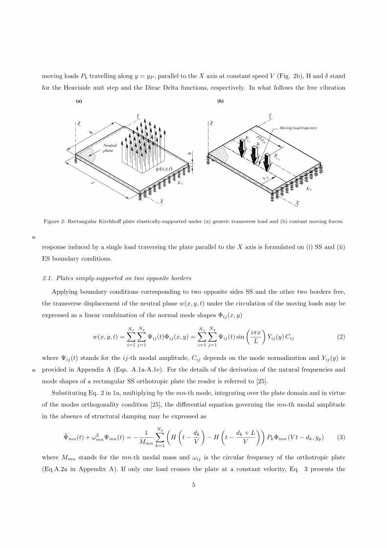
moving loads Pk travelling along y = yP , parallel to the X axis at constant speed V (Fig. 2b), H and δ stand
for the Heaviside unit step and the Dirac Delta functions, respectively. In what follows the free vibration
,t
Kv
Kv
Figure 2: Rectangular Kirchhoff plate elastically-supported under (a) generic transverse load and (b) contant moving forces.
90
response induced by a single load traversing the plate parallel to the X axis is formulated on (i) SS and (ii)
ES boundary conditions.
2.1. Plates simply-supported on two opposite borders
Applying boundary conditions corresponding to two opposite sides SS and the other two borders free,
the transverse displacement of the neutral plane w(x, y, t) under the circulation of the moving loads may be
expressed as a linear combination of the normal mode shapes Φij(x, y)
w(x, y, t) =
Nx∑i=1
Ny∑j=1
Ψij(t)Φij(x, y) =
Nx∑i=1
Ny∑j=1
Ψij(t) sin
(iπx
L
)Yij(y)Cij (2)
where Ψij(t) stands for the ij-th modal amplitude, Cij depends on the mode normalization and Yij(y) is
provided in Appendix A (Eqs. A.1a-A.1e). For the details of the derivation of the natural frequencies and95
mode shapes of a rectangular SS orthotropic plate the reader is referred to [25].
Substituting Eq. 2 in 1a, multiplying by the mn-th mode, integrating over the plate domain and in virtue
of the modes orthogonality condition [25], the differential equation governing the mn-th modal amplitude
in the absence of structural damping may be expressed as
Ψmn(t) + ω2mnΨmn(t) = − 1
Mmn
Np∑k=1
(H
(t− dk
V
)−H
(t− dk + L
V
))PkΦmn (V t− dk, yp) (3)
where Mmn stands for the mn-th modal mass and ωij is the circular frequency of the orthotropic plate
(Eq.A.2a in Appendix A). If only one load crosses the plate at a constant velocity, Eq. 3 presents the
5
following solution
Ψmn(t) =− PCmnYmn(yP )
Mmnω2mn
1
1−K2mn
[sin (Kmnωmnt)−Kmnsin (ωmnt)] 0 ≤ t ≤ L
VKmn 6= 1 (4a)
Ψmn(t) =− PCmnYmn(yP )
Mmnω2mn
1
2[sin (ωmnt)− ωmnt cos (ωmnt)] 0 ≤ t ≤ L
VKmn = 1 (4b)
where Kmn is the non-dimensional speed parameter defined as
Kmn =mπV
ωmnL(5)
Notice that in the previous equations m corresponds to the number of half-sine waves travelled by the load
when crossing the plate in the mn-th mode. As the load travels parallel to the X axis, the modal deflection
along the load path is always a sinusoidal function. When the load exits the plate, the latter is left in free
vibration. The amplitude of this free vibration stage may be obtained solving Eq. 6 with initial conditions
given by Eq. 4 at t = L/V .
Ψmn(t) + ω2mnΨmn(t) = 0 t ≥ L/V (6)
If the amplitude of the free vibrations is divided by the static solution when the load acts at (L/2, yP ), Ψstmn,
a non-dimensional amplitude in free vibration associated to a certain mode may be defined and expressed
as
Rmn =Ψmn
Ψstmn
=Kmn
√2
1−K2mn
√1− cos (mπ) cos
(mπ
Kmn
)Ψstmn =
∣∣∣∣−PCmnYmn(yP )
Mmnω2mn
∣∣∣∣ (7)
In Fig. 3 the evolution of Rmn with Kmn is represented. Rmn curves superimpose for modes with the100
same m value. Maximum free vibration and cancellation conditions alternatively take place. Modes with
the same m value present identical non-dimensional speeds for maximum free vibration and cancellation
(i.e. first longitudinal bending, first torsion and first transverse bending modes). Nevertheless, dimensional
velocities will differ if natural frequencies are different. The particular conditions for maximum free vibration
and cancellation are obtained and presented in section 2.3.105
2.2. Plates elastically-supported on two opposite borders
Let us consider vertical elastic supports uniformly distributed along x = 0 and x = L (Fig. 2a). Let Kv
be the vertical stiffness constant per unit of length of the plate border. As in [10], a new parameter κ is
defined as the ratio between the longitudinal flexural stiffness of the plate and that of the vertical supports
κ = DxBπ3/KvL
3, where Kv is the resultant vertical stiffness along one border of the plate. Following
Leissa’s approach [26], the plate transverse displacement may be approximated as a linear combination of
the product of two functions Xi(x) and Yj(y).
w(x, y, t) =
Nx∑i=1
Ny∑j=1
Ψij(t)Φij(x, y) =
Nx∑i=1
Ny∑j=1
Ψij(t)Xi(x)Yj(y)Cij (8)
6

Kmn
1lo
ca
l m
ax.
st
1lo
ca
l m
ax.
st
1lo
ca
l m
ax.
st
1ca
ncell
ati
on
st
1ca
ncell
ati
on
st
1ca
ncell
ati
on
st
2lo
ca
l m
ax.
nd
2lo
ca
l m
ax.
nd
2lo
ca
l m
ax.
nd
2ca
ncell
ati
on
nd
2ca
ncell
ati
on
nd
2ca
ncell
ati
on
nd
R1
nR
2n
R3
n
m=1 (a)
(b)
(c)
m=2
m=3
Figure 3: Rmn versus non-dimensional speed Kmn in SS plates for modes with one, two and three half-sine waves along the
load path (m = 1, 2, 3).
where Xi(x) and Yj(y) are approximated as the mode shapes of the associated undamped beams having
the same boundary conditions as the plate in the X and Y directions, respectively. For the details of the
formulation the reader is referred to Appendix A (Eqs. A.3 to A.6).
Following the same approach as in the SS case, in virtue of the modes orthogonality condition and ne-
glecting structural damping, one concludes that Eq. 3 governs again the ES plate mn-th modal amplitude
under the circulation of a single load travelling at constant speed, with the only difference that now Φmn
stands for the ES plate mode. As the load moves parallel to the longitudinal axis, admitting the approxima-
tion of the ES plate modes as the product of the corresponding beams modes, the modal load time variation
is proportional to that of a ES beam subjected to the same loading conditions. The solution for the forced
vibration of a Bernoulli-Euler ES beam under a single load was first presented in a compact format by
Museros et al. and may be consulted in [10]. From the modal amplitude and its derivative at the time
instant when the load exits the plate, the mn-th modal response in free vibration may be obtained. Finally,
the modal amplitude in free vibration can be defined as in the SS plate case applying a proper normalization
7

as
Rmn =Ψmn
Ψstmn
= f(Kmn
)Ψstmn =
∣∣∣∣−PCmnYmn(yP )
Mmnω2mn
∣∣∣∣ (9)
For clarification, an overbar is used in what follows to differentiate magnitudes corresponding to the ES
plate. In Eq. 9 Kmn is defined as the ratio between the forcing frequency of the load and the ES plate
circular frequency, ω2mn (Eq.A.6 in Appendix A). In order to be able to compare Rmn curves for different
support conditions, the following relation between Kmn and Kmn is admitted between the ES and the SS
plate, even though it strictly applies to the beam case:
Kmn =λmV
ωmnL' mπ
λmKmn (10)
When Rmn is plotted vs Kmn in the ES plate case a similar evolution to that shown in Fig. 3 is observed,110
where cancellation and maximum free vibration conditions alternate as the velocity increases. In the next
subsection these values are computed for SS and ES boundary conditions.
2.3. Non-dimensional speeds for maximum modal response and cancellation
In the previous section it was shown that the amplification of the free vibrations in SS or ES orthotropic
rectangular plates after the circulation of a single load can be expressed in terms of only one parameter, the
non-dimensional speed Kmn. From Eqs. 7 and 9 it is possible to obtain the conditions for maximum free
vibration and cancellation in each mode as
Rmn (Kmn) = 0 =⇒ Kcimn
∂Rmn(Kmn)
∂Kmn= 0 =⇒ Kmax,i
mn (11)
In Eq. 11 Kcimn for i = 1, 2, 3, . . . stands for the values of Kmn of cancellation as the velocity decreases
(i.e. Kc1mn is the first cancellation taking place at the highest speed). Likewise, Kmax,i
mn designates the non-115
dimensional speeds leading to a local maximum of the plate free vibrations, corresponding Kmax,1mn to the
local maximum taking place at the highest speed. In Fig. 3, first and second cancellation speeds and local
maxima are indicated for the SS plate modes with m = 1, 2, 3. In Table 1 the values for the first three
cancellation and maximum free vibration speeds are included for modes with m=1, κ = 0 (SS case) and
κ = [0.05, 0.1] (ES case). Only the values associated to m = 1 are included as the main focus of this study120
is the response of girder or slab decks associated to the first longitudinal bending, first torsion and first
transverse bending modes, which presumably will have the highest contribution to the overall transverse
response for frequencies up to 30 Hz. Notice that these values coincide with those of the SS and the ES
beams [10] due to the expression for the load in modal coordinates. In section 4, these ratios are compared
to real cancellation and maximum free vibration conditions computed numerically, and their accuracy is125
evaluated within a catalogue of realistic structures.
8

κKci
1n Kmax,i1m
i = 1 i = 2 i = 3 i = 4 i = 1 i = 2 i = 3 i = 4
0.0 0.3333 0.2000 0.1429 0.1111 0.7314 0.2576 0.1687 0.1258
0.05 0.3323 0.1997 0.1427 0.1109 0.7288 0.2563 0.1684 0.1254
0.10 0.3312 0.1991 0.1419 0.1100 0.7242 0.2556 0.1673 0.1245
Table 1: Analytical values for the first four cancellation and maximum free vibration speeds.
3. Forced vibrations of orthotropic rectangular plates under a series of moving loads: maxi-
mum resonance and cancellation of resonance
When a beam or a plate is traversed by a series of equidistant loads moving at constant speed, the
excitation may induce resonance on it. Resonance can occur when the time interval between the passage
of loads sequences separated a characteristic distance dk is a multiple of a natural period de the structure.
The conditions for resonance in a SS (Eq. 12a) or an ES (Eq. 12b) rectangular plate can be formulated in
a dimensional or non-dimensional format as
V rmn =dkfmnj
→Krmn =
m
2j
dkL
(12a)
V rmn =dkfmnj
→Krmn '
λmmπ
Krmn =
(λmπ
)21
2mj
dkL
(12b)
where j is the resonance order, or number of oscillations that the plate undergoes in a particular mode
between the passage of two consecutive loads separated a distance dk. At resonance, the free vibrations
that every single axle leaves on the structure add in phase and the plate response progressively increases.
Consequently, the amplitude of the free vibrations at the particular resonant speed, will determine to an
important extent the prominence of the resonant peak. When a resonant speed coincides or is close to a
maximum free vibration condition, an important amplification of the response should be expected. On the
contrary, as it approaches to a cancellation condition, it will become almost imperceptible. Based on the
previous, the conditions for resonance and either maximum free vibration or cancellation are equated, and
L/dk ratios for maximum resonance or cancellation of it are extracted both for the SS (Eq. 13) and the ES
(Eq. 14) plates:
Krmn = Kci
mn →(L
dk
)cimj
=m
2j
1
Kcimn
(13a)
Krmn = Kmax,i
mn →(L
dk
)max,imj
=m
2j
1
Kmax,imn
(13b)
9

Krmn = Kci
mn →(L
dk
)cimj
=
(λmπ
)21
2mj
1
Kcimn
(14a)
Krmn = Kmax,i
mn →(L
dk
)max,imj
=
(λmπ
)21
2mj
1
Kmax,imn
(14b)
In Table 2, L/dk ratios for maximum resonance and cancellation of resonance are included for m = 1,
κ = [0.00, 0.05, 0.10], first four resonant orders j, and first four cancellation or local maxima events i. The130
ratios are computed by substitution of the results in Table 1 into Eqs. 13 and 14. These values coincide with
those of SS and ES beams presented in [10], as it is justified through the derivations presented in section 2.
In section 4, the accuracy of analytical Kci1n and Kmax,i
1n from Table 1 and, therefore that of the L/dk ratios
included in Table 2, is evaluated in the case of 112 real bridges with skewed geometries.
j(L/dk)
ci1j κ = 0 (L/dk)
max,i1j κ = 0
i = 1 i = 2 i = 3 i = 4 i = 1 i = 2 i = 3 i = 4
1 1.5000 2.5000 3.5000 4.5000 0.6836 1.9411 2.9640 3.9737
2 0.7500 1.2500 1.7500 2.2500 0.3418 0.9705 1.4820 1.9869
3 0.5000 0.8333 1.1667 1.5000 0.2279 0.6470 0.9880 1.3246
4 0.3750 0.6250 0.8750 1.1250 0.1709 0.4853 0.7410 0.9934
j(L/dk)
ci1j κ = 0.05 (L/dk)
max,i1j κ = 0.05
i = 1 i = 2 i = 3 i = 4 i = 1 i = 2 i = 3 i = 4
1 1.4582 2.4263 3.3966 4.3689 0.6650 1.8864 2.8787 3.8605
2 0.7291 1.2132 1.6983 2.1844 0.3325 0.9432 1.4394 1.9302
3 0.4861 0.8088 1.1322 1.4563 0.2217 0.6288 0.9596 1.2868
4 0.3646 0.6066 0.8491 1.0922 0.1662 0.4716 0.7197 0.9651
j(L/dk)
ci1j κ = 0.10 (L/dk)
max,i1j κ = 0.10
i = 1 i = 2 i = 3 i = 4 i = 1 i = 2 i = 3 i = 4
1 1.4195 2.3620 3.3133 4.2731 0.6493 1.8394 2.8101 3.7761
2 0.7098 1.1810 1.6567 2.1366 0.3246 0.9197 1.4051 1.8880
3 0.4732 0.7873 1.0440 1.4244 0.2164 0.6131 0.9367 1.2587
4 0.3549 0.5905 0.8283 1.0683 0.1623 0.4599 0.7025 0.9440
Table 2: L/dk ratios leading to cancellation of resonance and maximum resonance for modes with m = 1 and κ = [0, 0.05, 0.10].
10

4. Sensitivity analysis on plate obliquity and supports vertical flexibility135
4.1. Methodology
In order to evaluate the applicability of the previously derived analytical ratios, first, an extensive
bridge catalogue is designed covering lengths from 10 to 25 m, considering longitudinal flexural stiffnesses
representative of both existing structures belonging to conventional lines and new stiffer bridges specifically
designed for HS lines, accounting for obliquity levels in the range 0◦ to 45◦ and envisaging the absence or140
presence of neoprene bearings at the supports. A total of 112 bridges are pre-dimensioned and evaluated.
In sections 4.1.1, 4.1.2 and 4.1.3 the specific properties of the bridges under study, the main assumptions of
the numerical model and the types of analyses performed are described.
4.1.1. Definition of a bridge catalogue
A representative ensemble of double-track, simply-supported pre-stressed concrete girder decks has been145
designed with the purpose of covering the mechanical properties of most existing bridges belonging to
conventional and high-speed railway lines of this typology. Among the different bridge typologies that can
be found in short-to-medium span lengths, precast decks composed by double-T girders have been selected
due to their low intrinsic torsional stiffness which makes their dynamic behaviour significantly differ from
that of a beam-type structure, exhibiting a noticeable contribution of the first torsion and first transverse150
bending modes to the vertical acceleration response under railway excitation [24]. Even though in new
railway lines in the range of lengths of interest these bridges have been replaced by stiffer solutions with
better dynamic performance (i.e. twin cell box girder decks), in the first HS Spanish line, Madrid-Sevilla,
several double-T girder bridges exist (see Fig. 4), and many may be found in conventional lines as well.
This typology usually covers span lengths between 10 m and 25 m with slenderness ratios (depth/span) no155
higher than 1/13.
Fig. 5 and Table 3 show, respectively, the cross section and main properties of the bridge catalogue.
Considered span lengths range from 10 to 25 m in 2.5 m intervals. Two longitudinal flexural stiffness ratios
L/δ (span length/maximum vertical displacement under static UIC-71 load model from Eurocode 1 [27])
are evaluated for each span: L/δ ratios in the range [2000-3000], which are more frequent in conventional160
lines (from now on L/δ2000 bridges), and L/δ > 3000 for HS lines (from now on L/δ3000 bridges). The
number of longitudinal girders of the decks, Ng, is also provided in Table 3. Bridges with 5 or 6 girders
have been pre-dimensioned in each case. The nominal value for the concrete strength fck assumed for the
upper slab is 30 MPa; for the longitudinal girders a value of fck = 50 MPa is considered. In a first approach,
the stiffening effect of hypothetical cross beams at the end sections is not included, as (i) these elements165
are not always present or may not be properly incorporated; and (ii) in previous works by the authors [28]
it has been shown that the effect of these elements on the first three modal shapes of this type of bridges
11

Figure 4: Precast pre-stressed double-T girder decks in Madrid-Sevilla HS line.
Figure 5: Intermediate cross section of the girder bridges of study.
is limited. Regarding the vertical support of the girders, two possibilities are envisaged: rigid supports (SS
deck) and flexible supports, accounting for the neoprene bearings vertical stiffness (ES deck). In the ES
case the relative flexibility of the bearings with respect to the flexural flexibility of the plate assumed is170
a reasonable and common estimate leading to a decrease of the fundamental frequency of the bridges of
approximately 3 − 4% (κ = 0.05). Furthermore, four obliquity levels for each deck are analysed: 0◦, 15◦,
30◦ and 45◦.
In Fig. 6 the first three natural frequencies of the bridges under study are represented. The natural
frequencies are computed from a modal analysis using the numerical model described in section 4.1.2.175
The first three mode shapes in frequency order of all the bridges that conform the catalogue are the first
longitudinal bending, first torsion and first transverse bending modes. The evolution of these three natural
frequencies with the level of obliquity is presented in section 4.2.1. Solid markers correspond to bridges with
12

Span L [m] h [m]Longitudinal girders Mass Supports
L/δ BrNameNg dg [m] hg [m] Ih[m4] [kg/m] κ
10 0.22 6 2.0 0.6 0.01098 18765 0(SS), 0.05 2119 B100.2000.6
0.22 5 2.275 0.65 0.02150 20525 0(SS), 0.05 3320 B100.3000.5
12.5 0.25 6 2.0 0.8 0.02278 19995 0(SS), 0.05 2229 B125.2000.6
0.22 5 2.0 0.85 0.04339 20975 0(SS), 0.05 3148 B125.3000.5
15 0.25 6 2.0 1.0 0.03961 20355 0(SS), 0.05 2154 B150.2000.6
0.25 5 2.275 1.05 0.07423 22295 0(SS), 0.05 3226 B150.3000.5
17.5 0.25 6 2.0 1.2 0.06195 20715 0(SS), 0.05 2090 B175.2000.6
0.25 5 2.275 1.25 0.11476 22745 0(SS), 0.05 3079 B175.3000.5
20 0.25 6 2.0 1.4 0.09029 21075 0(SS), 0.05 2031 B200.2000.6
0.25 6 2.0 1.45 0.16571 24590 0(SS), 0.05 3351 B200.3000.6
22.5 0.25 6 2.0 1.6 0.1251 21435 0(SS), 0.05 1977 B225.2000.6
0.25 5 2.275 1.65 0.23652 24396 0(SS), 0.05 3250 B225.3000.5
25 0.25 6 2.0 1.7 0.21812 24302 0(SS), 0.05 2320 B250.2000.6
0.25 5 2.275 1.85 0.131500 24896 0(SS), 0.05 3126 B250.3000.5
Table 3: Bridge catalogue definition for a particular obliquity level.
infinitely rigid supports and voided markers to the ES decks. Also, squares represent natural frequencies of
the most flexible predesigned bridges for each length, while circles are used for bridges with higher flexural180
stiffness, representative of new structures which may exist in HS railway lines. Finally, in Fig. 6(a) the
upper and lower limits of the fundamental frequency for simplified analysis according to Eurocode 1 [27] are
indicated.
4.1.2. Numerical model description
The dynamic response of the previously described bridges under railway traffic is obtained numerically185
in the time domain. The main features of the numerical model, sketched in Fig.7, are the following:
• An orthotropic thin plate is used to calculate the deck dynamic response under railway traffic. The
plate is discretised in C1 compatible linear varying curvature triangular finite elements with 12 degrees
of freedom [29].
• The weight of the dead loads (ballast, sleepers, rails, sidewalks and handrails) is uniformly distributed190
over the plate. No additional rigidity from the rail components is considered in a first approach.
• The laminated rubber bearings of the deck girders are included in the model as an equivalent vertical
stiffness uniformly distributed along the supports lengths. In a previous publication the authors have
13

L (m) L (m) L (m)
94.76 L-0.748
23.58 L-0.592
f 1(H
z)
f 2(H
z)
f 3(H
z)
L/d3000
L/d2000
SS ES
(a) (b) (c)
Figure 6: First three natural frequencies of the bridges under study in the straight configurations (α = 0).
proven that the uniform distribution of the girders and bearings vertical stiffness admitted in the
orthotropic plate model is not determinant for the calculation of the maximum response at the deck195
intermediate sections for moderate frequency contents [7].
• Constant moving loads represent the railway excitation, therefore neglecting vehicle-structure interac-
tion effects. As the track rigidity is not included in the numerical model, when a load enters or exits the
bridge crossing a border element, a transient phenomenon takes place due to the presence of the elastic
bearings that leads to unrealistic high-frequency modal contributions of the plate. To overcome this200
numerical problem, the load distributive effect of rails, sleepers and ballast is simulated in the model at
the abutments vicinity. To this end, the value of each axle load is modulated throughout a load-print
distributive function centred on the wheel position and based on the Zimmerman-Timoshenko solution
for an infinite beam on a Winkler foundation [30].
• The dynamic equations of motion are transformed into modal space and numerically integrated in the205
time domain applying the Newmark-β linear acceleration algorithm.
The orthotropic plate constants, Dx, Dy, D1, D2, Dxy and Dyx, are computed for each of the bridges of
the catalogue from its geometry and material data. The calculated values for these constants are given in
Table 4. For further details on this step the reader is referred to the classical reference [31].
14

Figure 7: Orthotropic plate FE model.
4.1.3. Numerical analyses performed210
First, the modal properties of the bridges under study are obtained with the aim of evaluating the
evolution of the lowest natural frequencies with the deck obliquity and the supports vertical flexibility.
Second, the free vibration response under the circulation of a single load of all the bridges is computed,
and speeds for cancellation and maximum free vibration are extracted for the first three modes. Results
are compared with the analytical predictions given in Table 1, and errors when using these predictions in215
skewed and ES decks are delimited. Finally, the effect of structural damping is shown on a subset of short
bridges.
4.2. Sensitivity analysis results
4.2.1. Evolution of modal parameters
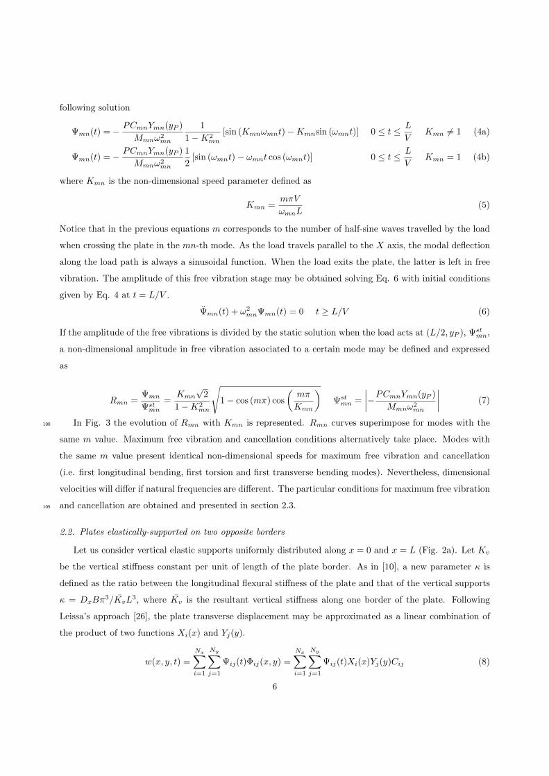
In Fig. 8 the variations of the first three natural frequencies of the bridges under study with respect220
to their homologous in the straight case (α = 0) are represented. Figures 8(a)-(b), 8(c)-(d) and 8(e)-(f)
represent the variations of the first bending, first torsion and first transverse bending frequencies, respectively.
The left column plots correspond to the SS case (κ = 0.0) and the right column ones to the ES case for
κ = 0.05. Finally, the results of the less stiff bridges (L/δ2000) are indicated with solid traces and those of
bridges with highest flexural stiffness (L/δ3000), are indicated with solid circles.225
From the analyses of these results it can be concluded that (i) the level of obliquity leads to an increase
in the decks natural frequencies with a highest impact on the shortest spans (10 m), the bridges with
lowest flexural stiffness (L/δ2000) and the highest skew angle (45◦); (ii) the previous tendency occurs both
in SS and ES structures, although in the latter case the increments are slightly inferior; (iii) frequency
variations increase with the mode number. The maximum detected variations reach 6%, 10% and 18% for230
the fundamental, first torsion and first transverse bending modes, respectively; (iv) as the length increases,
15

BrName Dx [Nm] Dy [Nm] D1,2 [Nm] Dxy [Nm] Dyx [Nm]
B100.2000.6 6.960E8 3.092E7 6.183E6 3.877E7 2.473E7
B100.3000.5 1.090E9 3.092E7 6.183E6 6.721E7 2.473E7
B125.2000.6 1.332E9 4.537E7 9.073E6 5.128E7 3.629E7
B125.3000.5 1.880E9 3.092E7 6.183E6 6.977E7 2.473E7
B150.2000.6 2.096E9 4.537E7 9.073E6 5.224E7 3.629E7
B150.3000.5 3.138E9 4.537E7 9.073E6 8.401E7 3.629E7
B175.2000.6 3.075E9 4.537E7 9.073E6 5.319E7 3.629E7
B175.3000.5 4.530E9 4.537E7 9.073E6 8.670E7 3.629E7
B200.2000.6 4.285E9 4.537E7 9.073E6 5.415E7 3.629E7
B200.3000.6 7.069E9 4.537E7 9.073E6 1.000E8 3.629E7
B225.2000.6 5.742E9 4.537E7 9.073E6 5.510E7 3.629E7
B225.3000.5 9.368E9 4.537E7 9.073E6 1.143E8 3.629E7
B250.2000.6 8.984E9 4.537E7 9.073E6 1.050E8 3.629E7
B250.3000.5 1.201E10 4.537E7 9.073E6 1.180E8 3.629E7
Table 4: Plate models orthotropic constants corresponding to bridges of the catalogue.
the effect of the deck obliquity diminishes, falling under 10% for the longest spans in all the cases.
4.2.2. Free vibration under a single load moving at constant speed
The free vibration response of the bridges under study after the passage of a constant moving load is
analysed in this section. The objectives are to (i) investigate if cancellation and maximum free vibration235
speeds occur and alternate as in the analytical straight SS case (subsection 2.3); and (ii) verify the adequacy
of the ratios provided in Table 1 to predict these phenomena with the increase of the plate obliqueness.
Finally, conclusions regarding the effect of structural damping are provided.
First, the free vibration response of the 112 bridges under study after the circulation of a single load is
obtained in the absence of damping. The load travels in all the cases with the same eccentricity (1/4 of
the deck width). In the SS case (κ = 0) and for the straight configurations (α = 0) this response coincides
with that shown in Fig. 3(a). The maximum modal displacement in the first three modes is obtained
for several travelling speeds. The range of speeds considered is such that the first cancellation and second
maximum of the free vibrations are reached and a sufficiently small velocity increment is selected to obtain
these two conditions with accuracy (∆V = 10−4 m/s). The second maximum is evaluated as the first one
will correspond to an unrealistic high speed with existing bridges and railway convoys. Finally the errors
16
1.00
1.05
1.10
1.15
1.20
7.5 10 12.5 15 17.5 20 22.5 25 27.5
f 2/f
2,a
=0
k=
0.0
5
L (m)
1.00
1.05
1.10
1.15
1.20
7.5 10 12.5 15 17.5 20 22.5 25 27.5
f 1/f
1,a
=0
k=
0
L (m)
1.00
1.05
1.10
1.15
1.20
7.5 10 12.5 15 17.5 20 22.5 25 27.5
f 1/f
1,a
=0
k=
0.0
5
L (m)
1.00
1.05
1.10
1.15
1.20
7.5 10 12.5 15 17.5 20 22.5 25 27.5
f 2/f
2,a
=0
k=
0
L (m)
1.00
1.05
1.10
1.15
1.20
7.5 10 12.5 15 17.5 20 22.5 25 27.5
f 3/f
3,a
=0
k=
0
L (m)
1.00
1.05
1.10
1.15
1.20
7.5 10 12.5 15 17.5 20 22.5 25 27.5
f 3/f
3,a
=0
k=
0.0
5
L (m)
(a)
(c)
(e)
(b)
(d)
(f)
a=45º L/d3000
L/d2000
a=15º
a=30º
a=0º
a=45º L/d3000
L/d2000
a=15º
a=30º
a=0º
Figure 8: Relative variations of first three natural frequencies for the complete bridge catalogue with respect to the straight
reference case (α = 0◦).
17

with respect to the theoretical predictions given in Table 1 are obtained as per
Ec11n(%) =Kc1
1n −Kc11n,an
Kc11n,an
· 100 Emax,21n (%) =Kmax,2
1n −Kmax,21n,an
Kmax,21n,an
· 100 (15)
where −an indicates the analytical values provided in Table 1, and Kc11n and Kmax,2
1n are computed from the
actual velocities applying Eqs. 5 and 10 for the SS and the ES case, respectively.240
In Fig. 9 the errors in the estimation of the first cancellation Kc11n of the free vibrations (plots 9(a)-
(b)-(c)) and the second maximum Kmax,21n (plots 9(d)-(e)-(f)) are computed according to Eq. 15 for all the
bridges and represented for the case of rigid supports (i.e. κ = 0.0) and for the first flexural, first torsion
and first transverse bending modes. Again, the results corresponding to the most flexible bridges (L/δ2000)
are indicated in solid trace and those of bridges with higher flexural stiffness (L/δ3000) are represented with245
solid circles. From the analysis of the results it can be concluded that (i) in the case of the fundamental
and the first torsion modes, both the first cancellation and second maximum speeds can be approximated
with the analytical values from the straight plate (Table 1) with errors lower than 1% even for the highest
levels of obliqueness considered; (ii) for the third mode, bridges with the highest skew angle (45◦) and least
flexural stiffness lead to the highest deviations, which reach 21% for the 1st cancellation and 14% for the250
2nd maximum. This is due to the fact that with the increase of obliquity the third mode deflection along
the load path diverges from the pure half-sine function; (iii) in the the great majority of analysed cases the
errors are negative, as the real dimensionless cancellation and maximum free vibration speeds are smaller
than the theoretical ones. This happens because with the plate obliquity the dimensional speeds for these
two situations reduce and the natural frequencies increase in all the cases.255
Fig. 10 shows the same results for the bridges with flexible supports (κ = 0.05). From the analysis of
the results it can be concluded that (i) if the fundamental and torsion modes first cancellation and second
maximum are approximated by the theoretical values from Table 1, the relative errors admitted are negligible
for the 1st cancellation (< 0.2%) and lower than 2% for the 2nd maximum; (ii) as in the SS case, errors are
higher than 2% only for the transverse bending mode (n = 3). In this case, errors for the 1st cancellation260
reach 3.3% for straight plates and diminish up to −16% for the most oblique ones. The second maximum is
better approximated with a maximum error of −9.9% for plates with α = 45◦. In general these errors are
higher for L/δ2000 bridges and are not much affected by the bridge length.
From the previously presented analysis it can be inferred that for the 1st longitudinal bending and 1st
torsion mode, the non-dimensional values for the speeds causing cancellation or maximum free vibration of265
the orthotropic plate simply or elastically supported that are proposed in section 2 are good estimates in the
case of oblique plates, even in highly skewed configurations. The previous conclusions are directly applicable
to the L/dk theoretical ratios for maximized and cancelled resonances included in Table 2, in virtue of Eqs.
13 and 14.
Finally, the effect of damping on the free vibration response is briefly presented. From the catalogue, the270
18

a=45º L/d3000
L/d2000
a=15º
a=30º
a=0º
(a)
(d)
(b)
(e)
(c)
(f)
L (m) L (m) L (m)
E(
= 0
.00
)k
c1
1n
n=1
n=1
n=2
n=2
n=3
n=3
E(
= 0
.00
)k
ma
x,2
1n
10 12.5 15 17.5 20 22.5 25
10 12.5 15 17.5 20 22.5 2510 12.5 15 17.5 20 22.5 25
10 12.5 15 17.5 20 22.5 2510 12.5 15 17.5 20 22.5 25
10 12.5 15 17.5 20 22.5 25
Figure 9: Variation of second maximum and first cancellation conditions in free vibration, Emax,21m (%) and Ec1
1m(%), for the
simply-supported bridges κ = 0.0 of the bridge catalogue with respect to the straight reference case (κ = 0, α = 0◦) .
L (m) L (m) L (m)
a=45º L/d3000
L/d2000
a=15º
a=30º
a=0º
E(
= 0
.05
)k
c1
1n
E(
= 0
.05
)k
ma
x,2
1n
10 12.5 15 17.5 20 22.5 25
10 12.5 15 17.5 20 22.5 2510 12.5 15 17.5 20 22.5 25
10 12.5 15 17.5 20 22.5 2510 12.5 15 17.5 20 22.5 25
10 12.5 15 17.5 20 22.5 25
(a)
(d)
(b)
(e)
(c)
(f)n=1
n=1
n=2
n=2
n=3
n=3
Figure 10: Variation of second maximum and first cancellation conditions in free vibration, Emax,21m (%) and Ec1
1m(%), for the
elastically-supported bridges κ = 0.05 of the bridge catalogue with respect to the straight reference case (κ = 0.05, α = 0◦)
19

bridge with L = 10 m, L/δ2000 and α = 0 is selected as a representative example. Nevertheless the conclusions
derived from it are applicable to the remaining cases. Fig. 11 shows the non-dimensional amplitude of the
free vibrations for the second mode computed considering modal damping ratios ζ1n = [0, 1, 2, 3] %. Fig.
11(a) corresponds to the SS case (κ = 0.0) and Fig. 11(b) to the ES case (κ = 0.05). R1n is represented versus
the speed parameter K1n computed as per Eqs. 5 and 10 for n = 2. The same evolution is identified for the275
first and third modes and only the case of the torsion mode is presented for the sake of brevity. The presence
of damping has two main effects: (i) the modal amplitudes reduce, especially in the vicinity of the local
maxima; (ii) the plate vibrations are not completely cancelled at the cancellation speeds. Nevertheless, and
for the low levels of damping expected in railway bridges, cancellation phenomena will still be noticeable
and the non-dimensional speeds for either cancellation or maximum free vibration should be adequately280
predicted with the theoretical values provided in Table 1.
(b)n = 2
1nz = 0.00
1nz = 0.01
1nz = 0.02
1nz = 0.03
(a)n = 2
1nz = 0.00
1nz = 0.01
1nz = 0.02
1nz = 0.03
K1nK1n
R(
= 0
.05
)k
1n
R(
= 0
.00
)k
1n
Figure 11: R1n vs. K1n for the second mode (n = 1; m = 2). L = 10 m, L/δ2000, α = 0. (a) κ = 0.0, (b) κ = 0.05.
In the next section the response of an existing bridge under HS railway traffic is presented. Two trains
induce resonance of two different modes associated to the length of the passengers’ cars (dk). The particular
L/dk ratios are computed in each case and conclusions regarding their proximity to maximum and cancelled
resonances analytical predictions, and the relation with the type of measured response are discussed.285
5. Experimental measurements on a real structure undergoing resonance
5.1. Structural description
Arroyo Bracea bridge was specifically constructed in the early 1990s for the Madrid-Sevilla first HS
railway line in Spain. It is composed by two identical SS bays with spans of 15.25 m and a width of
11.6 m. The deck is made of a 25 cm thick concrete slab resting over five prestressed double-T girders with290
20
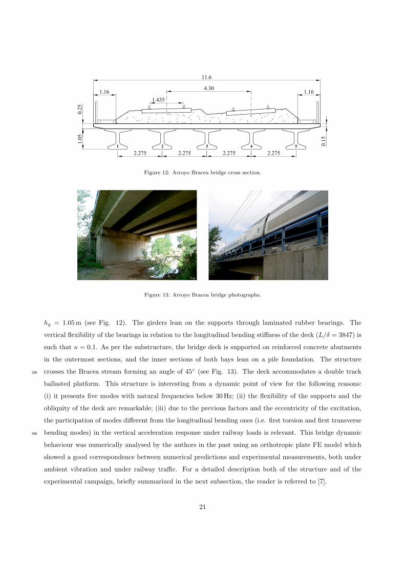
Figure 12: Arroyo Bracea bridge cross section.
Figure 13: Arroyo Bracea bridge photographs.
hg = 1.05 m (see Fig. 12). The girders lean on the supports through laminated rubber bearings. The
vertical flexibility of the bearings in relation to the longitudinal bending stiffness of the deck (L/δ = 3847) is
such that κ = 0.1. As per the substructure, the bridge deck is supported on reinforced concrete abutments
in the outermost sections, and the inner sections of both bays lean on a pile foundation. The structure
crosses the Bracea stream forming an angle of 45◦ (see Fig. 13). The deck accommodates a double track295
ballasted platform. This structure is interesting from a dynamic point of view for the following reasons:
(i) it presents five modes with natural frequencies below 30 Hz; (ii) the flexibility of the supports and the
obliquity of the deck are remarkable; (iii) due to the previous factors and the eccentricity of the excitation,
the participation of modes different from the longitudinal bending ones (i.e. first torsion and first transverse
bending modes) in the vertical acceleration response under railway loads is relevant. This bridge dynamic300
behaviour was numerically analysed by the authors in the past using an orthotropic plate FE model which
showed a good correspondence between numerical predictions and experimental measurements, both under
ambient vibration and under railway traffic. For a detailed description both of the structure and of the
experimental campaign, briefly summarized in the next subsection, the reader is referred to [7].
21

Figure 14: Arroyo Bracea bridge plan and sensors locations.
5.2. Experimental campaign305
In 2016 the authors carried out an experimental campaign with the purpose of characterizing the structure
and soil dynamic properties along with the bridge dynamic response under railway traffic. During the
campaign, the vertical acceleration of the bridge deck was measured at 11 points of the lower flange lower
horizontal face of the pre-stressed concrete girders (points 1 - 11 in Fig. 14), and at the pile foundation upper
horizontal surface, close to the central girder support (point 12 in Fig. 14). First, the modal parameters of310
the bridge were identified from ambient vibration data by state-space models using MACEC software [32].
Five modes were identified with frequencies below 30 Hz, in particular: 9.25 Hz, 10.63 Hz, 12.75 Hz, 17.92 Hz
and 24.57 Hz. The first three modal shapes correspond to the first longitudinal bending, first torsion and
first transverse bending modes. Modal damping values were identified as well for the first five modes with
values 2.0%, 1.61%, 1.30%, 0.80% and 0.95%.315
5.3. Resonant behaviour of the bridge
During the campaign, several trains crossed the bridge with circulating velocities in the range [100, 280] km/h.
For the purpose of this study, the structural response under only two of these trains is presented as in these
cases the travelling velocities were in the vicinity of theoretical resonant speeds. These trains are RENFE
Class 103 (ICE 3 or S103) circulating at 279 km/h and RENFE Class 130 (Talgo 250 or S130) crossing the320
bridge at 247 km/h. In Table 5 the theoretical resonant velocities associated to the first and second modes
of the bridge deck (first longitudinal bending and first torsion modes) and to the length of the passengers’
cars are included for the first three resonance orders. For the S103 and S130 trains these lengths are 24.8
and 13.1 m, respectively.
In Table 5 two resonant speeds are highlighted: the third resonance of the fundamental mode induced325
by the S103 train and the second resonance of the first torsion mode induced by the S130 train. It can be
22

Train V (km/h) dk (m) n Mode V r11n (km/h) V r21n (km/h) V r31n (km/h)
S103 279 24.8 1 1st L. bending 825.0 412.5 275.0
S130 247 13.1 2 1st Torsion 502.8 251.4 167.6
Table 5: Arroyo Bracea bridge first theoretical resonance speeds associated to S103 and S130 passengers’ cars lengths.
observed that these two theoretical critical velocities are in the vicinity of the actual circulating velocities
of the trains and, therefore, could lead to a certain structural amplification.
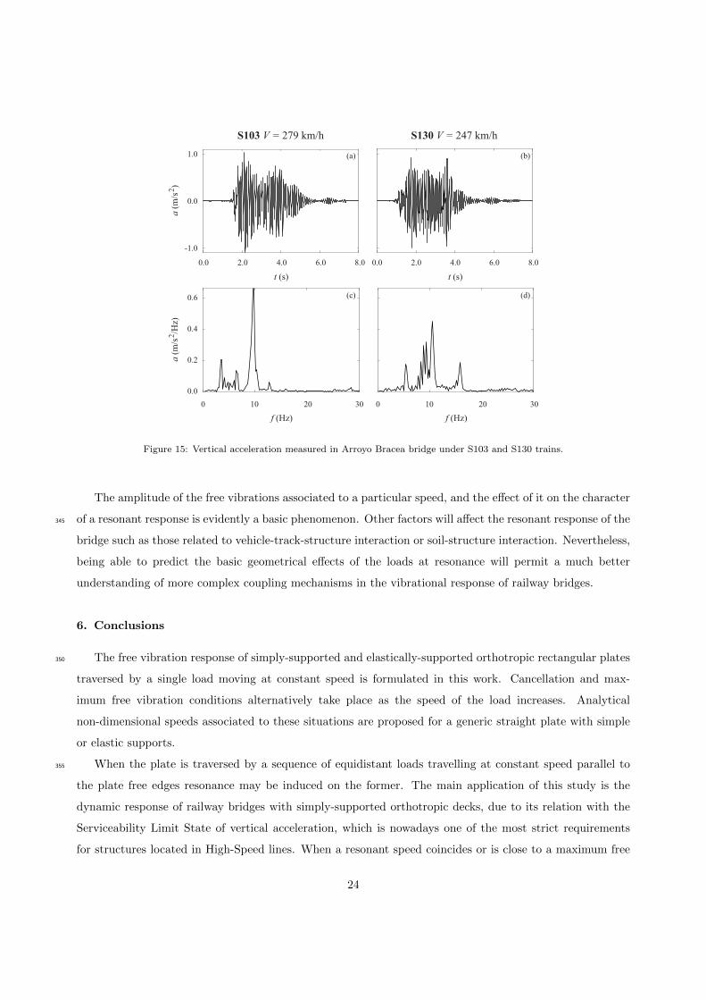
In what follows the experimental structural response is shown for these two convoys. In Fig. 15 the
bridge vertical acceleration is represented at sensor number 5 located at mid-span below girder #1 for the330
two trains S103 and S130. Plots 15(a) and 15(b) show the acceleration time history and plots (c) and (d)
the frequency content. From Fig. 15 it is evident that train S103 travelling at 279 km/h induces resonance
of the fundamental mode. The response progressively builds up and a peak in the frequency domain close to
the identified fundamental frequency (9.25 Hz) clearly prevails. This type of response is consistent with that
in the rest of the sensors. It should be stressed at this point that the maximum acceleration of the bridge is335
admissible despite the resonant situation according to the Serviceability Limit State of vertical acceleration
in ballasted bridges (amax ≤ 3.5 m/s2). On the other hand, the circulation of S130 train at 247 km/h induces
a second resonance of the first torsion mode as well. The comparison of the bridge responses at sensors 5
and 6 (not included) confirms this statement. Also, in Fig. 15 it may be observed that the acceleration peak
at the second mode frequency (torsion mode) of 10.63 Hz exceeds that of the fundamental mode.340
It can be affirmed that both trains induce resonance on the bridge to a certain extent. Nevertheless, the
amplification associated to the circulation of train S103 is much more evident, especially in the frequency
domain, than the one associated to train S130, even though the former is a third resonance (one loaded and
two empty cycles of oscillation between consecutive loads) and the latter is a second resonance (one loaded
and one empty cycle of oscillation between consecutive loads). In the view of the authors this difference in
amplitude could be related, at least partially, with the level of free vibrations that every axle load leaves on
the structure at the particular velocity of circulation in each mode. If ratios L/dk are calculated for both
trains: (L
dS103
)=
15.25
24.8= 0.61 '
(L
dk
)max,i=2
m=1,j=3
= 0.6131|κ=0.1 (16a)
(L
dS130
)=
15.25
13.1= 1.16 '
(L
dk
)c,i=2
m=1,j=2
= 1.1810|κ=0.1 (16b)
Eq. 16a shows how the L/dk ratio for the S103 train is close to a condition of maximum resonance for the
third resonance of modes with m = 1 (see Table 2). On the other hand, Eq. 16b shows that the L/dk ratio
for the S130 train is close to a cancellation condition for second resonances of also modes with m=1.
23
a(m
/s )
2a
(m/s
/H
z)2
t (s)
S103 V = 279 km/h
(a)
(c)
S130 V = 247 km/h
f (Hz) f (Hz)
t (s)
1.0
0.4
0.6
0.0
0.2
-1.0
0.0
0.0 2.0 4.0 6.0 8.0 0.0 2.0 4.0 6.0 8.0
0 10 20 30 0 10 20 30
(b)
(d)
Figure 15: Vertical acceleration measured in Arroyo Bracea bridge under S103 and S130 trains.
The amplitude of the free vibrations associated to a particular speed, and the effect of it on the character
of a resonant response is evidently a basic phenomenon. Other factors will affect the resonant response of the345
bridge such as those related to vehicle-track-structure interaction or soil-structure interaction. Nevertheless,
being able to predict the basic geometrical effects of the loads at resonance will permit a much better
understanding of more complex coupling mechanisms in the vibrational response of railway bridges.
6. Conclusions
The free vibration response of simply-supported and elastically-supported orthotropic rectangular plates350
traversed by a single load moving at constant speed is formulated in this work. Cancellation and max-
imum free vibration conditions alternatively take place as the speed of the load increases. Analytical
non-dimensional speeds associated to these situations are proposed for a generic straight plate with simple
or elastic supports.
When the plate is traversed by a sequence of equidistant loads travelling at constant speed parallel to355
the plate free edges resonance may be induced on the former. The main application of this study is the
dynamic response of railway bridges with simply-supported orthotropic decks, due to its relation with the
Serviceability Limit State of vertical acceleration, which is nowadays one of the most strict requirements
for structures located in High-Speed lines. When a resonant speed coincides or is close to a maximum free
24

vibration condition, a prominent resonant peak in the response of the deck, should be expected. On the360
other hand, when it is close to a cancellation condition, the resonant response will be mild or may not even
be perceptible for the particular mode. By equating maximum free vibration and cancellation conditions to
the resonance ones, bridge length-to-characteristic distance ratios are obtained and presented for maximum
or cancelled resonances for SS and ES rectangular orthotropic plates. Why these conditions coincide with
those of a simple beam, in the SS case, and are well approximated by those of an ES beam, in the ES case365
is justified through the analytical formulation.
The previous analytical conditions, obtained in the ideal (undamped and straight) case, are presented in
simple tables and are proposed for any bridge deck with an orthotropic plate behaviour. Their adequacy in
order to predict the real values of cancellation and maximum free vibration velocities, or the corresponding
L/dk ratios for maximum resonance or cancellation of it in the case of oblique decks, with different longitudi-370
nal bending stiffness and flexibility of the supports, is investigated numerically. To this end a comprehensive
bridge catalogue of 112 skewed bridges covering realistic parameters is pre-designed and a sensitivity study
is performed. The main conclusions extracted are:
• For the 1st longitudinal bending and 1st torsion modes, the non-dimensional values for the speeds
causing cancellation or maximum free vibration of the orthotropic plate that are proposed in section375
2 are very good estimates for the real values in the case of oblique plates, even in highly skewed
configurations, both in the simply-supported and in the elastically supported case.
• The first transverse bending mode, generally the third in frequency order in the bridge typologies
under study, is more affected by the plate obliquity and incurred errors approach 20% for the highest
obliquity levels and most flexible bridges considered.380
• In the presence of damping the modal amplitudes reduce, specially in the vicinity of the local maxima,
and the plate vibrations are not completely cancelled at the cancellation speeds. Nevertheless, and for
the low levels of damping expected in railway bridges, cancellation phenomena will still be noticeable
and the non-dimensional speeds for either cancellation or maximum free vibration should be adequately
predicted with the analytical values provided.385
Finally the experimental response of an existing bridge under HS railway traffic is presented. Two trains
induce resonance of two different modes associated to the length of the passengers’ cars. The level of free
vibrations is evaluated and discussed in relation to the type of response in each case.
The amplitude of the free vibrations associated to a particular speed, and the effect of it on the character
of a resonant response is evidently a basic phenomenon. Other factors will affect the resonant response of the390
bridge such as those related to vehicle-track-structure interaction or soil-structure interaction. Nevertheless,
being able to predict the basic geometrical effects of the loads at resonance will permit a much better
25

understanding of more complex coupling mechanisms in the vibrational response of railway bridges.
Acknowledgements
The authors would like to acknowledge the financial support provided by (i) the Spanish Ministries395
of Economy and Competitiveness and of Education under research project [BIA2016-75042-C2] and under
”Jose Castillejo” grant CAS18/00080 for mobility of researchers; (ii) the Andalusian Scientific Computing
Centre (CICA); (iii) Generalitat Valenciana AICO/2019/175 research project for consolidable groups.
Appendix A.
In Eq. 2:
Yij(y) =δijcosh (φijy/L) + γijcos (ϑijy/L)
γijδij (cosh (φijB/L)− cos (ϑijB/L))− ϑijγijsinh (φijy/L) + φijδijsin (ϑijy/L)
ϑijγ2ij(sinh (φijB/L)− φijδ2ijsin (ϑijB/L)
) (A.1a)
φij =iπ√Dy
[(H2 −DxDy+
ρhDyL4ω2
ij
i4π4
) 12
+H
] 12
(A.1b)
ϑij =iπ√Dy
[(H2 −DxDy+
ρhDyL4ω2
ij
i4π4
) 12
−H] 1
2
(A.1c)
δij = Dyϑ2ij+i
2π2D1 +D2
2(A.1d)
γij = Dyφ2ij+i
2π2D1 +D2
2(A.1e)
In Eqs. A.1b and A.1c, ωij is the circular frequency of the orthotropic plate related to the roots of the
frequency equation (Eq. A.2b) ωij as per
ωij =
√Dyφ4ij − 2i2π2Hφ2ij + i4π4Dx
L2√ρh
(A.2a)
(ϑ2ijγ
4ij − φ2ijδ4ij
)sinh
(φij
B
L
)sin
(ϑij
B
L
)+ 2φijϑijγ
2ijδ
2ij
(cosh
(φij
B
L
)cos
(ϑij
B
L
)− 1
)= 0 (A.2b)
In Eq.8, corresponding to the transverse displacement of a plate elastically-supported along X and400
free-free (FF) along Y , the functions Xi(x) and Yj(y) may be expressed as [33, 34],
Xi(x) = sin
(λix
L
)+ sinh
(λix
L
)sin(λi)
sinh(λi)+ γ1i
(cos
(λix
L
)+ cosh
(λix
L
)+ γ2i sinh
(λix
L
))(A.3a)
γ1i =sinh(λi)− sin(λi)
(2/κ)(π/λn)3 sinh(λi) + cos(λi)− cosh(λi), γ2i =
cos(λi)− cosh(λi)
sinh(λi)(A.3b)
Yj(y) =
(cos
(λjy
B
)+ cosh
(λjy
B
))− cos(λj)− cosh(λj)
sin(λj)− sinh(λj)
(sin
(λjy
B
)+ sinh
(λjy
B
))(A.4)
26

where parameters λi and λj in the two directions are obtained from the respective frequency equations of
the ES (Eq. A.5a) and the FF (Eq. A.5b) beams as per(π3
κ
)2
+π3
κλ3i
sinh(λi)cos(λi)− cosh(λi)sin(λi)
sin(λi)sinh(λi)+ λ6i
1− cos(λi)cosh(λi)
2sin(λi)sinh(λi)= 0 (A.5a)
cos(λj)cosh(λj)− 1 = 0 (A.5b)
Note that Eq. A.5b leads to two rigid body modes corresponding to λj = 0. Then, the circular frequency
of the ij-th mode of the ES plate can be obtained by substitution of Eqs. A.3-A.5 into Eq. A.6
ω2ij =
1
Mmn
∫ L
0
∫ B
0
(Dx
∂4Φij∂x4
+ 2H∂4Φij∂x2∂y2
+Dy∂4Φij∂y4
)Φij(x, y) dydx (A.6a)
Mmn =
∫ L
0
∫ B
0
ρhΦij(x, y)2 dydx (A.6b)
References
[1] ADIF, Railway network statement 2019 (in Spanish), Tech. rep., Ministerio de Fomento - Gobierno de Espana (2019).
URL http://www.adifaltavelocidad.es/
[2] ERRI D214, Rail bridges for speeds > 200 km/h. Final report. Part a. Synthesis of the results of D 214 research, European405
Rail Research Institute, 1999.
[3] L. Fryba, Dynamic behaviour of bridges due to high-speed trains, in: Workshop bridges for high-speed railways, Porto,
2004, pp. 137–158.
[4] W. Hoorpah, Dynamic calculations of high-speed railway bridges in France some case studies, in: T. &. Francis (Ed.),
Dynamics of High-Speed Railway Bridges, no. 978-0-203-89540-5, 2008, pp. 133–146. doi:https://doi.org/10.1201/410
9780203895405.
[5] M. Zacher, M. Baebler, Dynamic behaviour of ballast on railway bridges, in: T. Francis (Ed.), Dynamics of High-Speed
Railway Bridges, no. 978-0-203-89540-5, 2008, pp. 99–112. doi:https://doi.org/10.1201/9780203895405.
[6] I. Bisus, Tipologıa de viaductos en las lıneas de alta velocidad en Espana, Master’s thesis, E.T.S. Ingenieros de Caminos,
Canales y Puertos de Barcelona, Universitat Politecnica de Catalunya (2009).415
URL http://hdl.handle.net/2099.1/12582
[7] P. Galvın, A. Romero, E. Moliner, M. Martınez-Rodrigo, Two FE models to analyse the dynamic response of short span
simply-supported oblique high-speed railway bridges: Comparison and experimental validation, Engineering Structures
167 (2018) 48–64. doi:https://doi.org/10.1016/j.engstruct.2018.03.052.
[8] Y. Yang, J. Yau, L. Hsu, Vibration of simple beams due to trains moving at high speeds, Engineering Structures 19(11)420
(1997) 936–944.
[9] E. Savin, Dynamic amplification factor and response spectrum for the evaluation of vibrations of beams under successive
moving loads, Journal of Sound and Vibration 248 (2) (2001) 267 – 288.
[10] P. Museros, E. Moliner, M. Martınez-Rodrigo, Free vibrations of simply-supported beam bridges under moving loads:
Maximum resonance, cancellation and resonant vertical acceleration, Journal of Sound and Vibration 332 (2) (2013) 326425
– 345.
[11] M. Simsek, M. Aydn, H. H. Yurtcu, J. N. Reddy, Size-dependent vibration of a microplate under the action of a moving
load based on the modified coupled stress theory, Acta Mechanica 226 (2015) 38073822. doi:10.1007/s00707-015-1437-9.
[12] J. Gbadeyan, O. S.T., Dynamic response of a mindlin elastic rectangular plate under a distributed moving mass, Journal
of Sound and Vibration 182 (5) (1995) 677–695. doi:10.1006/jsvi.1995.0226.430
27
[13] M. Shadnam, M. Mofid, J. Akin, On the dynamic response of rectangular plate, with moving mass, Thin-walled Structures
39 (2001) 797806. doi:10.1016/S0263-8231(01)00025-8.
[14] S. Lee, S. Yhim, Dynamic analysis of composite plates subjected to multi-moving loads based on a third order theory,
International Journal of Solids and Structures 41 (2004) 44574472. doi:10.1016/j.ijsolstr.2004.03.021.
[15] F. Au, M. Wang, Sound radiation from forced vibration of rectangular orthotropic plates under moving loads, Journal of435
Sound and Vibration 281 (2005) 10571075. doi:10.1016/j.jsv.2004.02.005.
[16] J. Gbadeyan, M. Dada, Dynamic response of a mindlin elastic rectangular plate under a distributed moving mass, Inter-
national Journal of Mechanical Sciences 48 (2006) 323340. doi:10.1016/j.ijmecsci.2005.09.005.
[17] P. Malekzadeh, A. Fiouz, H. Razi, Three-dimensional dynamic analysis of laminated composite plates subjected to moving
load, Composite Structures 90 (2) (2009) 105–114. doi:10.1016/j.compstruct.2009.02.008.440
[18] P. Malekzadeh, M. Haghighi, M. Gholami, Dynamic response of thick laminated annular sector plates subjected to moving
load, Composite Structures 92 (2010) 155163. doi:10.1016/j.compstruct.2009.07.020.
[19] E. Ghafoori, M. Asghari, Dynamic analysis of laminated composite plates traversed by a moving mass based on a first-order
theory, Composite Structuctures 92 (2010) 18651876. doi:10.1016/j.compstruct.2010.01.011.
[20] X. Zhu, S. Law, Dynamic behavior of orthotropic rectangular plates under moving loads, Journal of Engineering Mechanics445
129(1) (2003) 79–87.
[21] A. Nikkhoo, M. Ebrahimzadeh, S. Azam, J. Amiri, Vibration of a thin rectangular plate subjected to series of moving
inertial loads, Mechanics research communications 55 (2014) 105–113. doi:10.1016/j.mechrescom.2013.10.009.
[22] M. Ebrahimzadeh, N. Attari, A. Nikkhoo, S. Mariani, Resonance of a rectangular plate influenced by sequential moving
masses, Coupled Systems Mechanics 5 (1) (2016) 87–100. doi:10.12989/csm.2016.5.1.087.450
[23] M. Martınez-Rodrigo, P. Museros, Optimal design of passive viscous dampers for controlling the resonant response of
orthotropic plates under high-speed moving loads, Journal of Sound and Vibration 330 (2011) 13281351. doi:10.1016/j.
jsv.2010.10.017.
[24] E. Moliner, M. Martınez-Rodrigo, P. Museros, Dynamic performance of existing double track railway bridges at resonance
with the increase of the operational line speed, Engineering Structures 132 (2017) 98 – 109. doi:http://dx.doi.org/10.455
1016/j.engstruct.2016.11.031.
URL http://www.sciencedirect.com/science/article/pii/S0141029616312639
[25] W. H. N.J. Huffington, On the transverse vibrations of rectangular orthotropic plates, Journal of Applied Mechanics 25
(1958) 389 – 395.
[26] A. Leissa, Vibration of plates, Tech. Rep. NASA SP-160, NASA (1969).460
[27] CEN, EN 1991-2, Eurocode 1: Actions on Structures - Part 2: Traffic loads on bridges, European Committee for Stan-
dardization, Brussels, 2002.
[28] E. Moliner, A. Romero, P. Galvın, M. Martınez-Rodrigo, Effect of the end cross beams on the railway induced vibrations
of short girder bridges, Engineering Structures 201 (109728) (2019) 1–16.
[29] C. A. Felippa, Refined finite element analysis of linear and nonlinear two dimensional structures, Ph.D. thesis, University465
of California, Berkeley (1966).
[30] M. Martınez-Rodrigo, J. Lavado, P. Museros, Dynamic performance of existing high-speed railway bridges under resonant
conditions retrofitted with fluid viscous dampers, Engineering Structures 32 (3) (2010) 808 – 828. doi:https://doi.org/
10.1016/j.engstruct.2009.12.008.
URL http://www.sciencedirect.com/science/article/pii/S0141029609003927470
[31] A. R. Cusens, R. P. Pama, Bridge deck analysis, John Wiley & Sons, 1975.
[32] E. Reynders, System identification methods for (operational) modal analysis: review and comparison, Archives of Com-
putational Methods in Engineering 19 (1) (2010) 51–124.
28

[33] I. Karnovsky, O. Lebed, Formulas for structural dynamics, McGraw Hill, 2000.
[34] S. Rao, Vibration of continuous systems, John Wiley & Sons, 2007.475
29