maxpro nvr commissioning and installation guide · checking the creation of images ... provide...
TRANSCRIPT

Document 800-09355V2 – 03/2012
MAXPRO® NVR
Commissioning and Installation Guide


Revisions
Issue Date Description
1.0 July 7, 2011 New document
2.0 October 7, 2011 Added the “Upgrading MAXPRO NVR” section
3.0 January 27 , 2012 Updated the whole document with the MAXPRO NVR S/W-Only release
changes.
4.0 February 14, 2012 Updated the " Upgrading MAXPRO NVR" section
5.0 February 21, 2012 Changed two screen shots in ’Upgrading MAXPRO NVR’ section as per Build 21
6.0 March 1, 2012 Changed two screen shots in ’Upgrading MAXPRO NVR’ section as per Build 22

M A X P R O N V R
Table of Contents
1
Table of Contents
ABOUT THIS GUIDE . . . . . . . . . . . . . . . . . . . . . . . . . . . . . .5
OVERVIEW . . . . . . . . . . . . . . . . . . . . . . . . . . . . . . . . . . . . . . . 5INTRODUCING MAXPRO NVR . . . . . . . . . . . . . . . . . . . . . . . . . . . . 5
MAXPRO NVR SINGLE-BOX SOLUTION . . . . . . . . . . . . . . . . . . . . . . . . . . . . . . 5
MAXPRO NVR SOFTWARE ONLY SOLUTION . . . . . . . . . . . . . . . . . . . . . . . . . . . 5
INTENDED AUDIENCE . . . . . . . . . . . . . . . . . . . . . . . . . . . . . . . . . 6OVERVIEW OF CONTENTS . . . . . . . . . . . . . . . . . . . . . . . . . . . . . . 6CAUTIONS AND WARNINGS . . . . . . . . . . . . . . . . . . . . . . . . . . . . . . 6FCC COMPLIANCE STATEMENT . . . . . . . . . . . . . . . . . . . . . . . . . . . 7IMPORTANT SAFEGUARDS . . . . . . . . . . . . . . . . . . . . . . . . . . . . . . . 7WARRANTY AND SERVICE . . . . . . . . . . . . . . . . . . . . . . . . . . . . . . . 9RELATED DOCUMENTS . . . . . . . . . . . . . . . . . . . . . . . . . . . . . . . 10TYPOGRAPHICAL CONVENTIONS . . . . . . . . . . . . . . . . . . . . . . . . . . 10
COMMISSIONING PLAN . . . . . . . . . . . . . . . . . . . . . . . . . . . 11
OVERVIEW . . . . . . . . . . . . . . . . . . . . . . . . . . . . . . . . . . . . . . 11STEPS IN THE COMMISSIONING PROCESS . . . . . . . . . . . . . . . . . . . . . 11
SETTING UP THE MAXPRO NVR . . . . . . . . . . . . . . . . . . . . . . . . . . . . . . . . 11
INSTALLING THE SOFTWARE IN THE SERVER AND CLIENT COMPUTERS . . . . . . . . . . . . 11
CONFIGURING MAXPRO NVR. . . . . . . . . . . . . . . . . . . . . . . . . . . . . . . . . . 12
VERIFYING THE CONFIGURATION. . . . . . . . . . . . . . . . . . . . . . . . . . . . . . . . . 12
SETTING UP THE MAXPRO NVR . . . . . . . . . . . . . . . . . . . . . 13
OVERVIEW . . . . . . . . . . . . . . . . . . . . . . . . . . . . . . . . . . . . . . 13SETTINGS FOR THE MAXPRO NVR SINGLE-BOX SOLUTION . . . . . . . . . . 14
MAXPRO NVR XE SYSTEM DIAGRAM. . . . . . . . . . . . . . . . . . . . . . . . . . . . . . 14
MAXPRO NVR SE SYSTEM DIAGRAM. . . . . . . . . . . . . . . . . . . . . . . . . . . . . . 14
CHANGING THE MAXPRO NVR IP ADDRESS . . . . . . . . . . . . . . . . . . . . . . . . . . 15
CONNECTING THE MONITORS . . . . . . . . . . . . . . . . . . . . . . . . . . . . . . . . . . 17
TURNING ON THE MAXPRO NVR UNIT . . . . . . . . . . . . . . . . . . . . . . . . . . . . 17
SETTINGS FOR THE MAXPRO NVR SOFTWARE-ONLY SOLUTION . . . . . . . 18BEFORE YOU BEGIN. . . . . . . . . . . . . . . . . . . . . . . . . . . . . . . . . . . . . . . . 18
ACTIVITIES TO PERFORM IN THIS PHASE. . . . . . . . . . . . . . . . . . . . . . . . . . . . . 18
HARDWARE SPECIFICATIONS . . . . . . . . . . . . . . . . . . . . . . . . . . . . . . . . . . . 18
MAXPRO NVR SOFTWARE SYSTEM ARCHITECTURE . . . . . . . . . . . . . . . . . . . . . . 21

M A X P R O N V R
Table of Contents
2
MAXPRO NVR STANDALONE SYSTEM . . . . . . . . . . . . . . . . . . . . . . . . . . . . . . . . . 21
MAXPRO NVR DISTRIBUTED SYSTEM . . . . . . . . . . . . . . . . . . . . . . . . . . . . . . . . . 22
CONFIGURING THE MONITOR DISPLAY PROPERTIES . . . . . . . . . . . . . . 23CONNECTING THE KEYBOARD . . . . . . . . . . . . . . . . . . . . . . . . . . . 24
HOW TO LOG ON TO THE ULTRAKEY PLUS KEYBOARD?. . . . . . . . . . . . . . . 24
HOW TO LOG OFF FROM THE ULTRAKEY PLUS KEYBOARD? . . . . . . . . . . . . 24
INSTALLING MAXPRO NVR . . . . . . . . . . . . . . . . . . . . . . . .25
OVERVIEW . . . . . . . . . . . . . . . . . . . . . . . . . . . . . . . . . . . . . 25BEFORE YOU BEGIN . . . . . . . . . . . . . . . . . . . . . . . . . . . . . . . . . . . . . . . 25
SYSTEM REQUIREMENTS . . . . . . . . . . . . . . . . . . . . . . . . . . . . . . . . . . . . . 25
MAXPRO NVR INSTALLATION . . . . . . . . . . . . . . . . . . . . . . . . . . 27HOW TO INSTALL MAXPRO NVR . . . . . . . . . . . . . . . . . . . . . . . . 27FULL INSTALLATION . . . . . . . . . . . . . . . . . . . . . . . . . . . . . . . . 31CLIENT INSTALLATION . . . . . . . . . . . . . . . . . . . . . . . . . . . . . . . 35UPGRADING MAXPRO NVR . . . . . . . . . . . . . . . . . . . . . . . . . . . 37UNINSTALLING MAXPRO NVR . . . . . . . . . . . . . . . . . . . . . . . . . . 39
CLIENT UNINSTALL . . . . . . . . . . . . . . . . . . . . . . . . . . . . . . . . . . . . . . . . 39
FULL UNINSTALL . . . . . . . . . . . . . . . . . . . . . . . . . . . . . . . . . . . . . . . . . 40
CONFIGURING MAXPRO NVR . . . . . . . . . . . . . . . . . . . . . . .43
OVERVIEW . . . . . . . . . . . . . . . . . . . . . . . . . . . . . . . . . . . . . 43BEFORE YOU BEGIN . . . . . . . . . . . . . . . . . . . . . . . . . . . . . . . . . . . . . . . 43
FIREWALL SETTINGS . . . . . . . . . . . . . . . . . . . . . . . . . . . . . . . . 44SETTING AN INBOUND FIREWALL RULE FOR A PORT . . . . . . . . . . . . . . . . . . . . . . 45
SETTING AN OUTBOUND FIREWALL RULE FOR A PORT. . . . . . . . . . . . . . . . . . . . . 48
SETTING AN INBOUND FIREWALL RULE FOR AN APPLICATION . . . . . . . . . . . . . . . . . 48
SETTING AN OUTBOUND FIREWALL RULE FOR AN APPLICATION. . . . . . . . . . . . . . . . 51
CONFIGURING MAXPRO NVR . . . . . . . . . . . . . . . . . . . . . . . . . . 52CONFIGURING THE SYSTEM SETTINGS FOR MAXPRO NVR . . . . . . . . . . . . . . . . . . 53
CONFIGURING DISK MANAGEMENT SETTINGS . . . . . . . . . . . . . . . . . . . . . . . . . . 53
CONFIGURING THE CAMERAS. . . . . . . . . . . . . . . . . . . . . . . . . . . . . . . . . . . 53
CONFIGURING SCHEDULE BASED RECORDING FOR CAMERAS . . . . . . . . . . . . . . . . . . 53
PERFORMING USER ADMINISTRATION . . . . . . . . . . . . . . . . . . . . . . . . . . . . . . 53
VERIFYING THE CONFIGURATION . . . . . . . . . . . . . . . . . . . . .55
OVERVIEW . . . . . . . . . . . . . . . . . . . . . . . . . . . . . . . . . . . . . 55
M A X P R O N V R
Table of Contents
3
BEFORE YOU BEGIN. . . . . . . . . . . . . . . . . . . . . . . . . . . . . . . . . . . . . . . . 55
ACTIVITIES TO PERFORM IN THIS PHASE. . . . . . . . . . . . . . . . . . . . . . . . . . . . . 55
CHECKING THE CONNECTION WITH THE MAXPRO NVR SERVER . . . . . . . 56CHECKING THE DEVICE LISTING IN THE DEVICES WINDOW . . . . . . . . . . . 57CHECKING THE ACKNOWLEDGEMENT AND CLEARING OF ALARMS . . . . . . . 58CHECKING THE LIVE VIDEO FROM CAMERAS . . . . . . . . . . . . . . . . . . . 59CHECKING THE PLAYBACK OF RECORDED VIDEO . . . . . . . . . . . . . . . . 60CHECKING THE PANNING, TILTING, AND ZOOMING . . . . . . . . . . . . . . . 61CHECKING THE CREATION OF IMAGES . . . . . . . . . . . . . . . . . . . . . . . 62CHECKING THE CREATION OF CLIPS . . . . . . . . . . . . . . . . . . . . . . . . 63CHECKING THE SALVO VIEW FEATURE . . . . . . . . . . . . . . . . . . . . . . 64CHECKING THE SEARCH FOR RECORDED VIDEO IN MAXPRO NVR . . . . . . 65CHECKING THE GENERATION OF EVENT HISTORY/ OPERATOR LOG REPORT . 66

M A X P R O N V R
Table of Contents
4
This page is intentionally left blank

MAXPRO NVR Commissioning and Installation Guide 5
. . . . .
. . . . . . . . . . . . . . . . . . . . . . . . . . . . . . . . . . .ABOUT THIS GUIDE
. . . . . . . . . . . . . . . . . . . . . . . . . . . . . . . . . . . . . . . . . . . . . . . . . . . . . . . . . . .OVERVIEW
This guide describes the installation and commissioning guidelines for setting up the MAXPRO® NVR system.
. . . . . . . . . . . . . . . . . . . . . . . . . . . . . . . . . . . . . . . . . . . . . . . . . . . . . . . . . . .INTRODUCING MAXPRO NVR
MAXPRO® NVR is a Network Video Recorder (NVR) based on MAXPRO® VMS platform. MAXPRO® NVR is offered in the following two variants.
• MAXPRO® Single-box solution• MAXPRO® Software-Only solution
MAXPRO NVR SINGLE-BOX SOLUTIONMAXPRO NVR Single-box solution is available in the following two editions.
• MAXPRO NVR XE (Xpress Edition) supports up to 16 IP cameras.• MAXPRO NVR SE (Standard Edition) supports up to 32 IP cameras.
Honeywell’s MAXPRO NVR Single-boxed solution is an ideal solution for entry into IP video surveillance systems. MAXPRO NVR utilizes Honeywell's High-definition cameras to offer a powerful high definition IP recording and security monitoring system for different installations. MAXPRO NVR comes pre-installed with the required software and pre-licensed with the required channels depending on the MAXPRO NVR edition you purchase.
MAXPRO NVR SOFTWARE ONLY SOLUTIONHoneywell’s MAXPRO NVR Software is a flexible, scalable and open IP video surveillance system. Supporting Honeywell's high definition (HD) cameras and broad integration with third party IP cameras and encoders, the MAXPRO NVR family is a powerful HD IP recording and security monitoring system for a variety of applications. MAXPRO NVR Software ensures flexibility for end user IT departments when choosing NVR hardware in deploying a recording solution, but end users will find it as easy as a DVR to configure and operate. MAXPRO NVR Software is an open platform and supports broad third party device integrations with support for PSIA and ONVIF standards, real time streaming protocol (RTSP) standard and native device integrations. MAXPRO NVR provides easy to use desktop clients and mobile apps - MAXPRO®Mobile. MAXPRO NVR Software comes with all required software applications and a license for 32 channels allowing for up to 32 cameras as your system grows. Minimum hardware specifications for different levels of recording and monitoring performance are provided for IT departments to choose the appropriate hardware platform. This, along with quick and easy commissioning wizards for discovery and system configuration, makes installing HD IP systems quick and efficient without requiring any IP expertise. Simple and logical configuration pages make setup a breeze even for the novice installer.

AB OU T TH I S G U IDE
Intended Audience
6 MAXPRO NVR Commissioning and Installation Guide
. . . . . . . . . . . . . . . . . . . . . . . . . . . . . . . . . . . . . . . . . . . . . . . . . . . . . . . . . . .INTENDED AUDIENCE
This document is intended for field and commissioning engineers.
. . . . . . . . . . . . . . . . . . . . . . . . . . . . . . . . . . . . . . . . . . . . . . . . . . . . . . . . . . .OVERVIEW OF CONTENTS
The following table describes the contents of each chapter in this guide.
. . . . . . . . . . . . . . . . . . . . . . . . . . . . . . . . . . . . . . . . . . . . . . . . . . . . . . . . . . .CAUTIONS AND WARNINGS
Installation and servicing should be performed only by qualified and experienced technicians to conform to all local codes and to maintain your warranty.
WARNING! 12 VDC/24 VAC models require the use of CSA Certified/UL Listed Class 2 power adapters to ensure compliance with electrical safety standards
No Chapter Description
1 Commissioning Plan Description of the process involved in commissioning the MAXPRO NVR.
2 Setting up the MAXPRO NVR • Hardware specifications for MAXPRO NVR
• System diagrams for MAXPRO NVR.
• Configuring the monitor display properties.
• Procedures for connecting the keyboards.
3 Installing MAXPRO NVR Steps for installing MAXPRO NVR.
4 Configuring MAXPRO NVR Basic tasks for configuring MAXPRO NVR.
Verifying the Configuration Verifying the MAXPRO NVR configuration.

. .
. .
.
ABO UT T H I S GU I D E
FCC Compliance Statement
MAXPRO NVR Commissioning and Installation Guide 7
. . . . . . . . . . . . . . . . . . . . . . . . . . . . . . . . . . . . . . . . . . . . . . . . . . . . . . . . . . .FCC COMPLIANCE STATEMENT
Information to the User: This equipment has been tested and found to comply with the limits for a Class B digital device. Pursuant to Part 15 of the FCC Rules, these limits are designed to provide reasonable protection against harmful interference in a residential installation. This equipment generates, uses, and can radiate radio frequency energy and, if not installed and used in accordance with the instruction manual, may cause harmful interference to radio communications. However, there is no guarantee that interference will not occur in a particular installation.
If this equipment does cause harmful interference to radio or television reception, which can be determined by turning the equipment off and on, the user is encouraged to try to correct the interference by one of the following measures:
• Reorient or relocate the receiving antenna• Increase the separation between the equipment and receiver• Connect the equipment to an outlet on a circuit different from that to which the receiver is
connected• Consult the dealer or a radio/TV technician for help.
Caution: Changes or modifications not expressly approved by the party responsible for compliance could void the user’s authority to operate the equipment.
This Class B digital apparatus complies with Canadian ICES-003.Cet appareil numérique de la Classe B est conforme à la norme NMB-003 du Canada.
. . . . . . . . . . . . . . . . . . . . . . . . . . . . . . . . . . . . . . . . . . . . . . . . . . . . . . . . . . .IMPORTANT SAFEGUARDS
1. Read Instructions
All the safety and operating instructions should be read before the appliance is operated.
2. Retain Instructions
The safety and operating instructions should be retained for future reference.
3. Cleaning
Unplug this equipment from the wall outlet before cleaning it. Do not use liquid aerosol cleaners. Use a damp soft cloth for cleaning.
4. Attachments
Never add any attachments and/or equipment without the approval of the manufacturer as such additions may result in the risk of fire, electric shock, or other personal injury.
5. Water and/or Moisture
Do not use this equipment near water or in contact with water.
WEEE (Waste Electrical and Electronic Equipment). Correct disposal of this product (applicable in the European Union and other European countries with separate collection systems). This product should be disposed of, at the end of its useful life, as per applicable local laws, regulations, and procedures.
AB OU T TH I S G U IDE
Important Safeguards
8 MAXPRO NVR Commissioning and Installation Guide
6. Ventilation
Place this equipment only in an upright position. The equipment has an open-frame Switching Mode Power Supply (SMPS), which can cause a fire or electric shock if anything is inserted through the ventilation holes on the side of the equipment.
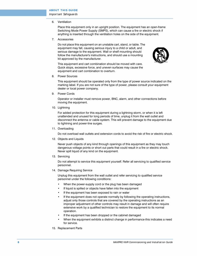
7. Accessories
Do not place this equipment on an unstable cart, stand, or table. The equipment may fall, causing serious injury to a child or adult, and serious damage to the equipment. Wall or shelf mounting should follow the manufacturer's instructions, and should use a mounting kit approved by the manufacturer.
This equipment and cart combination should be moved with care. Quick stops, excessive force, and uneven surfaces may cause the equipment and cart combination to overturn.
8. Power Sources
This equipment should be operated only from the type of power source indicated on the marking label. If you are not sure of the type of power, please consult your equipment dealer or local power company.
9. Power Cords
Operator or installer must remove power, BNC, alarm, and other connections before moving the equipment.
10. Lightning
For added protection for this equipment during a lightning storm, or when it is left unattended and unused for long periods of time, unplug it from the wall outlet and disconnect the antenna or cable system. This will prevent damage to the equipment due to lightning and power-line surges.
11. Overloading
Do not overload wall outlets and extension cords to avoid the risk of fire or electric shock.
12. Objects and Liquids
Never push objects of any kind through openings of this equipment as they may touch dangerous voltage points or short out parts that could result in a fire or electric shock. Never spill liquid of any kind on the equipment.
13. Servicing
Do not attempt to service this equipment yourself. Refer all servicing to qualified service personnel.
14. Damage Requiring Service
Unplug this equipment from the wall outlet and refer servicing to qualified service personnel under the following conditions:
• When the power-supply cord or the plug has been damaged• If liquid is spilled or objects have fallen into the equipment• If the equipment has been exposed to rain or water• If the equipment does not operate normally by following the operating instructions,
adjust only those controls that are covered by the operating instructions as an improper adjustment of other controls may result in damage and will often require extensive work by a qualified technician to restore the equipment to its normal operation.
• If the equipment has been dropped or the cabinet damaged• When the equipment exhibits a distinct change in performance-this indicates a need
for service.
15. Replacement Parts
. .
. .
.
ABO UT T H I S GU I D E
Warranty and Service
MAXPRO NVR Commissioning and Installation Guide 9
When replacement parts are required, be sure the service technician has used replacement parts specified by the manufacturer or that have the same characteristics as the original part. Unauthorized substitutions may result in fire, electric shock, or other hazards.
16. Safety Check
Upon completion of any service or repairs to this equipment, ask the service technician to perform safety checks to determine that the equipment is in proper operating condition.
17. Field Installation
This installation should be made by a qualified service person and should conform to all local codes.
18. Correct Batteries
WARNING! Risk of explosion if battery is replaced by an incorrect type. Dispose of used batteries according to the instructions.
19. Operating Temperature
An operating temperature range is specified so that the customer and installer may determine a suitable operating environment for the equipment.
20. Elevated Operating Ambient Temperature
If installed in a closed or multi-unit rack assembly, the operating ambient temperature of the rack environment may be greater than room ambient. Therefore, consideration should be given to installing the equipment in an environment compatible with the specified operating temperature range.
21. Reduced Air Flow
Installation of the equipment in the rack should be such that the amount of airflow required for safe operation of the equipment is not compromised.
22. Mechanical Loading
Mounting of the equipment in the rack should be such that a hazardous condition is not caused by uneven mechanical loading.
23. Circuit Overloading
Consideration should be given to connection of the equipment to supply circuit and the effect that overloading of circuits might have on over-current protection and supply wiring. Appropriate consideration of equipment nameplate ratings should be used when addressing this concern.
24. Reliable Earthing (Grounding)
Reliable grounding of rack mounted equipment should be maintained. Particular attention should be given to supply connections other than direct connections to the branch circuit (for example, use of power strips).
. . . . . . . . . . . . . . . . . . . . . . . . . . . . . . . . . . . . . . . . . . . . . . . . . . . . . . . . . . .WARRANTY AND SERVICE
Subject to the terms and conditions listed on the Product warranty, during the warranty period Honeywell will repair or replace, at its sole option, free of charge, any defective products returned prepaid.
In the event you have a problem with any Honeywell product, please call Customer Service at 1.800.796.CCTV for assistance or to request a Return Merchandise Authorization (RMA) number.
Be sure to have the model number, serial number, and the nature of the problem available for the technical service representative.

AB OU T TH I S G U IDE
Related Documents
10 MAXPRO NVR Commissioning and Installation Guide
Prior authorization must be obtained for all returns, exchanges, or credits. Items shipped to Honeywell without a clearly identified Return Merchandise Authorization (RMA) number may be refused.
. . . . . . . . . . . . . . . . . . . . . . . . . . . . . . . . . . . . . . . . . . . . . . . . . . . . . . . . . . .RELATED DOCUMENTS
This document listed in the table serves as a necessary prerequisite for understanding MAXPRO NVR.
. . . . . . . . . . . . . . . . . . . . . . . . . . . . . . . . . . . . . . . . . . . . . . . . . . . . . . . . . . .TYPOGRAPHICAL CONVENTIONS
This guide uses the following typographical conventions.
Document title Part number Description
MAXPRO NVR Operator’s Guide
800-09356V2 This document is written for everyday MAXPRO NVR users who perform the basic video surveillance operations.
Font What it represents Example
Swiss721 BT Words or characters that you must type. The word “enter” is used if you must type text and then press the Enter or Return key.
Enter the password.
Menu titles and other items you select Double-click Open from the File menu.
Buttons you click to perform actions Click Exit to close the program.
Trebuchet MS Heading Installation
Cross-reference to external source Refer to the System Administrator Guide.
Cross-reference within document See Installation.

MAXPRO NVR Commissioning and Installation Guide 11
1. . . . .
. . . . . . . . . . . . . . . . . . . . . . . . . . . . . . . . . . .COMMISSIONING PLAN
. . . . . . . . . . . . . . . . . . . . . . . . . . . . . . . . . . . . . . . . . . . . . . . . . . . . . . . . . . .OVERVIEW
Commissioning is the process of installing, configuring, and setting up the MAXPRO NVR system hardware and software. At the end of the commissioning process, the MAXPRO NVR system is equipped for use by operators to perform video surveillance operations.
. . . . . . . . . . . . . . . . . . . . . . . . . . . . . . . . . . . . . . . . . . . . . . . . . . . . . . . . . . .STEPS IN THE COMMISSIONING PROCESS
The process of commissioning involves the following phases.
SETTING UP THE MAXPRO NVRSetting up the MAXPRO NVR involves:
• Determining the number of MAXPRO NVR server and client computers at the location.
• Choosing the desired MAXPRO NVR system architecture.
• Connecting the monitors to the MAXPRO NVR. After connecting the monitors, configure the monitor display properties.
• Connecting the serial keyboards (for example, Ultrakey) to the MAXPRO NVR unit.
Note: See Setting up the MAXPRO NVR for information on how to setup the MAXPRO NVR system.
INSTALLING THE SOFTWARE IN THE SERVER AND CLIENT COMPUTERS
Caution: For the Honeywell’s boxed solutions: MAXPRO NVR SE and MAXPRO NVR XE, the server and client software is already installed on the box. Hence the instructions in this section are NOT applicable.
Installing the software involves the following steps:
• The server and client computers meet the minimum hardware and software requirements.
• Installing the MAXPRO NVR software.
C O M MI S S I O N I N G P L A N
Steps in the Commissioning Process
12 MAXPRO NVR Commissioning and Installation Guide
1
Note: See Installing MAXPRO NVR for information on software requirements and installation instructions for the MAXPRO NVR software.
CONFIGURING MAXPRO NVRIn this phase, you need to configure the MAXPRO NVR through the user interface. Configuring MAXPRO NVR includes the following:
• Configuring the cameras• Configuring the system level settings• Configuring the disk management settings• Configuring the schedule based recording for cameras• Performing user administration
Note: See Configuring MAXPRO NVR for information on how to configure the MAXPRO
NVR system.
VERIFYING THE CONFIGURATION• Verifying the configuration involves checking whether the surveillance operations can be
performed using MAXPRO NVR. Surveillance operations include: viewing the live video, performing the pan, tilt, and zoom on the video, and starting the video recording.
Note: See Verifying the Configuration for information on how to perform the verification.

MAXPRO NVR Commissioning and Installation Guide 13
2. . . . .
. . . . . . . . . . . . . . . . . . . . . . . . . . . . . . . . . . .SETTING UP THE MAXPRO NVR
. . . . . . . . . . . . . . . . . . . . . . . . . . . . . . . . . . . . . . . . . . . . . . . . . . . . . . . . . . .OVERVIEW
This chapter describes the settings for setting up the MAXPRO NVR system.• For setting up the MAXPRO NVR Single-box solution, see the section Settings for the
MAXPRO NVR Single-box Solution.• For setting up the MAXPRO NVR Software-Only solution, see the section Settings for
the MAXPRO NVR Software-Only Solution.

S E T T I N G UP T H E MA X PRO N V R
Settings for the MAXPRO NVR Single-box Solution
14 MAXPRO NVR Commissioning and Installation Guide
2
SETTINGS FOR THE MAXPRO NVR SINGLE-BOX
. . . . . . . . . . . . . . . . . . . . . . . . . . . . . . . . . . . . . . . . . . . . . . . . . . . . . . . . . . .SOLUTION
Setting up the MAXPRO NVR unit and client computers is the first phase in the commissioningprocess.
Note: Refer to the MAXPRO NVR Quick Install Guide for information on hardware specifications for the MAXPRO NVR unit.
MAXPRO NVR XE SYSTEM DIAGRAMThe following figure illustrates the MAXPRO NVR XE (Xpress Edition) system diagram.
Figure 2-1 MAXPRO NVR XE System Diagram
MAXPRO NVR SE SYSTEM DIAGRAMThe following figure illustrates the NTSC version of MAXPRO NVR SE system diagram.

. .
. .
.
S E T T I N G UP T H E MA X PRO N V R
Settings for the MAXPRO NVR Single-box Solution
MAXPRO NVR Commissioning and Installation Guide 15
Figure 2-2 MAXPRO NVR SE System Diagram (NTSC Version)
The following figure illustrates the PAL version of MAXPRO NVR SE system diagram
Figure 2-3 MAXPRO NVR SE System Diagram (PAL Version)
CHANGING THE MAXPRO NVR IP ADDRESSThe MAXPRO NVR unit by default comes with the static IP address. If you are using a DHCP based network, the IP address settings on the MAXPRO NVR must be changed from static to DHCP.To change the MAXPRO NVR IP address1. After the MAXPRO NVR unit is booted, minimize the MAXPRO NVR application.

S E T T I N G UP T H E MA X PRO N V R
Settings for the MAXPRO NVR Single-box Solution
16 MAXPRO NVR Commissioning and Installation Guide
2
2. Choose Start>Control Panel. The Control Panel window appears.
3. Double-click Network Connections. The Network Connections window similar to the following figure appears.
Figure 2-4 Network Connections Window
4. Right-click your Local Area Network Connection, and click Properties. The Local Area Connection Properties dialog box similar to the following figure appears.
Figure 2-5 Local Area Connection Properties
5. Select the Internet Protocol Version4(TCP/IPv4) check box, and then click Properties. The Internet Protocol Version4(TCP/IPv4) Properties dialog box similar to the following figure appears.
. .
. .
.
S E T T I N G UP T H E MA X PRO N V R
Settings for the MAXPRO NVR Single-box Solution
MAXPRO NVR Commissioning and Installation Guide 17
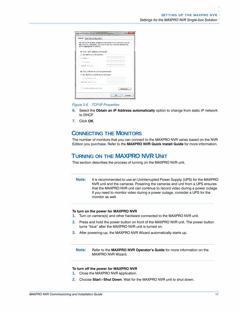
Figure 2-6 TCP/IP Properties
6. Select the Obtain an IP Address automatically option to change from static IP network to DHCP.
7. Click OK.
CONNECTING THE MONITORSThe number of monitors that you can connect to the MAXPRO NVR varies based on the NVR Edition you purchase. Refer to the MAXPRO NVR Quick Install Guide for more information.
TURNING ON THE MAXPRO NVR UNITThis section describes the process of turning on the MAXPRO NVR unit.
Note: It is recommended to use an Uninterrupted Power Supply (UPS) for the MAXPRO NVR unit and the cameras. Powering the cameras and unit from a UPS ensures that the MAXPRO NVR unit can continue to record video during a power outage. If you need to monitor video during a power outage, consider a UPS for the monitor as well.
To turn on the power for MAXPRO NVR1. Turn on camera(s) and other hardware connected to the MAXPRO NVR unit.
2. Press and hold the power button on front of the MAXPRO NVR unit. The power button turns “blue” after the MAXPRO NVR unit is turned on.
3. After powering-up, the MAXPRO NVR Wizard automatically starts up.
Note: Refer to the MAXPRO NVR Operator’s Guide for more information on the MAXPRO NVR Wizard.
To turn off the power for MAXPRO NVR1. Close the MAXPRO NVR application.
2. Choose Start>Shut Down. Wait for the MAXPRO NVR unit to shut down.
S E T T I N G UP T H E MA X PRO N V R
Settings for the MAXPRO NVR Software-Only Solution
18 MAXPRO NVR Commissioning and Installation Guide
2
SETTINGS FOR THE MAXPRO NVR SOFTWARE-ONLY
. . . . . . . . . . . . . . . . . . . . . . . . . . . . . . . . . . . . . . . . . . . . . . . . . . . . . . . . . . .SOLUTION
Setting up the MAXPRO NVR server and client computers is the first phase in the commissioning process. You can connect a maximum of 10 clients to a server.See the following sections.
BEFORE YOU BEGINDetermine the following at the location.
• Number of server and client computers• Hardware configuration of the computers• Number of serial devices such as joystick controllers (Ultrakey keyboard), switchers,
PITs, and other devices
ACTIVITIES TO PERFORM IN THIS PHASEThe following table lists the activities to be performed in this phase.
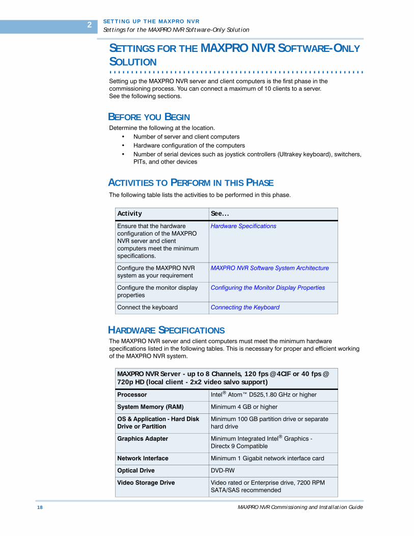
HARDWARE SPECIFICATIONSThe MAXPRO NVR server and client computers must meet the minimum hardware specifications listed in the following tables. This is necessary for proper and efficient working of the MAXPRO NVR system.
Activity See...
Ensure that the hardware configuration of the MAXPRO NVR server and client computers meet the minimum specifications.
Hardware Specifications
Configure the MAXPRO NVR system as your requirement
MAXPRO NVR Software System Architecture
Configure the monitor display properties
Configuring the Monitor Display Properties
Connect the keyboard Connecting the Keyboard
MAXPRO NVR Server - up to 8 Channels, 120 fps @ 4CIF or 40 fps @ 720p HD (local client - 2x2 video salvo support)
Processor Intel® Atom™ D525,1.80 GHz or higher
System Memory (RAM) Minimum 4 GB or higher
OS & Application - Hard Disk Drive or Partition
Minimum 100 GB partition drive or separate hard drive
Graphics Adapter Minimum Integrated Intel® Graphics - Directx 9 Compatible
Network Interface Minimum 1 Gigabit network interface card
Optical Drive DVD-RW
Video Storage Drive Video rated or Enterprise drive, 7200 RPM SATA/SAS recommended
. .
. .
.
S E T T I N G UP T H E MA X PRO N V R
Settings for the MAXPRO NVR Software-Only Solution
MAXPRO NVR Commissioning and Installation Guide 19
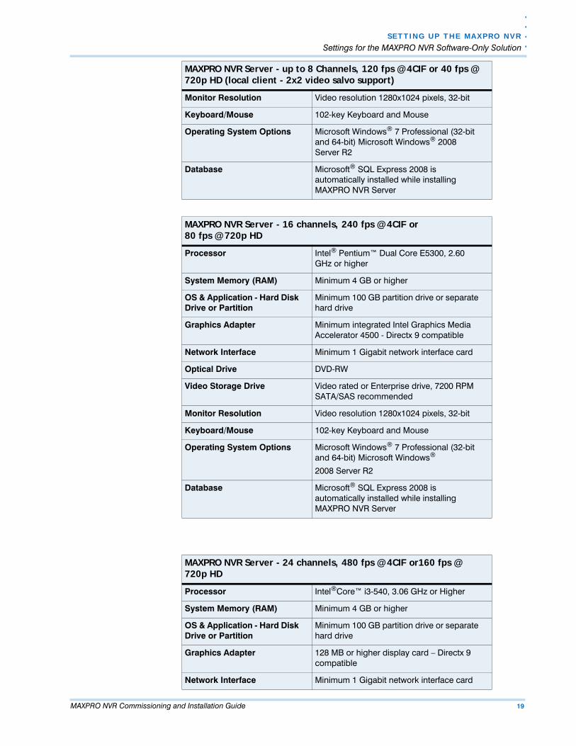
Monitor Resolution Video resolution 1280x1024 pixels, 32-bit
Keyboard/Mouse 102-key Keyboard and Mouse
Operating System Options Microsoft Windows® 7 Professional (32-bit and 64-bit) Microsoft Windows® 2008 Server R2
Database Microsoft® SQL Express 2008 is automatically installed while installing MAXPRO NVR Server
MAXPRO NVR Server - 16 channels, 240 fps @ 4CIF or80 fps @ 720p HD
Processor Intel® Pentium™ Dual Core E5300, 2.60 GHz or higher
System Memory (RAM) Minimum 4 GB or higher
OS & Application - Hard Disk Drive or Partition
Minimum 100 GB partition drive or separate hard drive
Graphics Adapter Minimum integrated Intel Graphics Media Accelerator 4500 - Directx 9 compatible
Network Interface Minimum 1 Gigabit network interface card
Optical Drive DVD-RW
Video Storage Drive Video rated or Enterprise drive, 7200 RPM SATA/SAS recommended
Monitor Resolution Video resolution 1280x1024 pixels, 32-bit
Keyboard/Mouse 102-key Keyboard and Mouse
Operating System Options Microsoft Windows® 7 Professional (32-bit and 64-bit) Microsoft Windows®
2008 Server R2
Database Microsoft® SQL Express 2008 is automatically installed while installing MAXPRO NVR Server
MAXPRO NVR Server - up to 8 Channels, 120 fps @ 4CIF or 40 fps @ 720p HD (local client - 2x2 video salvo support)
MAXPRO NVR Server - 24 channels, 480 fps @ 4CIF or160 fps @ 720p HD
Processor Intel®Core™ i3-540, 3.06 GHz or Higher
System Memory (RAM) Minimum 4 GB or higher
OS & Application - Hard Disk Drive or Partition
Minimum 100 GB partition drive or separate hard drive
Graphics Adapter 128 MB or higher display card – Directx 9 compatible
Network Interface Minimum 1 Gigabit network interface card

S E T T I N G UP T H E MA X PRO N V R
Settings for the MAXPRO NVR Software-Only Solution
20 MAXPRO NVR Commissioning and Installation Guide
2
Optical Drive DVD-RW
Video Storage Drive Video rated or Enterprise drive, 7200 RPM SATA/SAS recommended
Monitor Resolution Video resolution 1280x1024 pixels,32-bit
Keyboard/Mouse 102-key Keyboard and Mouse
Operating System
Options
Microsoft Windows® 7 Professional (32-bit and 64-bit) Microsoft Windows® 2008 Server R2
Database Microsoft® SQL Express 2008 is automatically installed while installing MAXPRO NVR Server
MAXPRO NVR Server - 24 channels, 480 fps @ 4CIF or160 fps @ 720p HD
MAXPRO NVR Server - 32 channels, 960 fps @ 4CIF or640 fps @ 720p HD
Processor Intel®Core™ 2 Quad Q9400, 2.66 GHz or Higher
System Memory (RAM) Minimum 4 GB or higher
OS & Application - Hard Disk Drive or Partition
Minimum 100 GB partition drive or separate hard drive
Graphics Adapter 256 MB or higher display card - Directx 9 compatible
Network Interface Minimum 1 Gigabit network interface card
Optical Drive DVD-RW
Video Storage Drive Video rated or Enterprise drive, 7200 RPM SATA/SAS recommended
Monitor Resolution Video resolution 1280x1024 pixels,32-bit
Keyboard/Mouse 102-key Keyboard and Mouse
Operating System
Options
Microsoft Windows® 7 Professional (32-bit and 64-bit) Microsoft Windows® 2008 Server R2
Database Microsoft® SQL Express 2008 is
automatically installed while installing
MAXPRO NVR Server
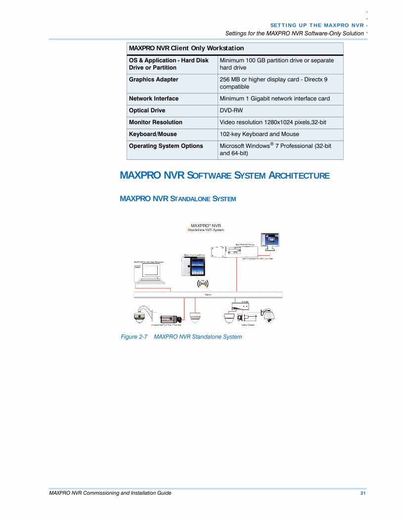
MAXPRO NVR Client Only Workstation
Processor Intel®Core™ 2 Duo Processor E6750 2.66 GHz or Quad Core Intel Xeon® E5405 2.0 GHz
System Memory (RAM) Minimum 4 GB or higher
. .
. .
.
S E T T I N G UP T H E MA X PRO N V R
Settings for the MAXPRO NVR Software-Only Solution
MAXPRO NVR Commissioning and Installation Guide 21
MAXPRO NVR SOFTWARE SYSTEM ARCHITECTURE
MAXPRO NVR STANDALONE SYSTEM
Figure 2-7 MAXPRO NVR Standalone System
OS & Application - Hard Disk Drive or Partition
Minimum 100 GB partition drive or separate hard drive
Graphics Adapter 256 MB or higher display card - Directx 9 compatible
Network Interface Minimum 1 Gigabit network interface card
Optical Drive DVD-RW
Monitor Resolution Video resolution 1280x1024 pixels,32-bit
Keyboard/Mouse 102-key Keyboard and Mouse
Operating System Options Microsoft Windows® 7 Professional (32-bit and 64-bit)
MAXPRO NVR Client Only Workstation
S E T T I N G UP T H E MA X PRO N V R
Settings for the MAXPRO NVR Software-Only Solution
22 MAXPRO NVR Commissioning and Installation Guide
2
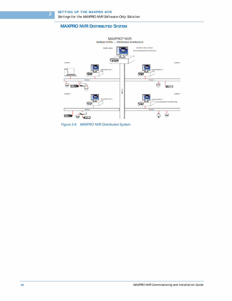
MAXPRO NVR DISTRIBUTED SYSTEM
Figure 2-8 MAXPRO NVR Distributed System
. .
. .
.
S E T T I N G UP T H E MA X PRO N V R
Configuring the Monitor Display Properties
MAXPRO NVR Commissioning and Installation Guide 23
. . . . . . . . . . . . . . . . . . . . . . . . . . . . . . . . . . . . . . . . . . . . . . . . . . . . . . . . . . .CONFIGURING THE MONITOR DISPLAY PROPERTIES
The recommended display settings for the monitor are dialog box resolution of 1280 x 1024 pixels and color quality of 65K colors non-interlaced. The display settings can be configured from the Windows control panel or from the Windows desktop through the context menu. To configure the display settings from the context menu in the Windows desktop 1. Right-click the Windows desktop to display the context-menu.
2. Click Properties. The Display Properties dialog box appears.
3. Click the Settings tab.
4. Select the dialog box resolution and color quality.
5. Click Apply to save the settings.
6. Click OK to close the dialog box.
To configure the display settings from the Windows control panel 1. Go to Windows control panel.
Note: To open the control panel, click Start > Settings > Control Panel.
2. Double-click the Display icon. The Display Properties dialog box appears.
3. Click the Settings tab.
4. Select the dialog box resolution and color quality.
5. Click Apply to save the settings.
6. Click OK to close the dialog box.
S E T T I N G UP T H E MA X PRO N V R
Connecting the Keyboard
24 MAXPRO NVR Commissioning and Installation Guide
2
. . . . . . . . . . . . . . . . . . . . . . . . . . . . . . . . . . . . . . . . . . . . . . . . . . . . . . . . . . .CONNECTING THE KEYBOARD
Keyboards (all the supported models of MAXPRO VMS) can be connected to MAXPRO NVR without any configuration.You can also connect Honeywell’s UltraKey keyboard that represents an industry-leading approach to intelligent, user-friendly control of video management systems. Using the UltraKey keyboard, you can perform actions such as selecting a panel, PTZ operations, selecting a video source such as a camera, and others in the Viewer tab. To connect a Keyboard to MAXPRO NVR• Connect the keyboard to the DB-9 Connector on the rear panel of the MAXPRO NVR unit.
Or• Alternatively the UltraKey can be connected through the Ethernet. Set the UltraKey IP
Address and System Controller (IP Address of MAXPRO NVR) through the UltraKey configuration settings. For more information, refer to the UltraKey manual.
HOW TO LOG ON TO THE ULTRAKEY PLUS KEYBOARD?First time users of MAXPRO NVR must explicitly logon to UltraKey Plus keyboard in order touse MAXPRO NVR.To logon to the UltraKey Plus keyboard1. Power-on the UltraKey Plus keyboard.
2. Press the Menu key on the LCD.
3. Press the MAX-1000 Setup key on the LCD. The Left, Up, Right, and Down buttons appear on the LCD.
4. Press the Ent hard key located on the right side of the UltraKey Plus keyboard.
5. Enter the default PIN password 1234.
6. Press Ent. The UltraKey Plus keyboard is now ready for use for performing the video management functions.
HOW TO LOG OFF FROM THE ULTRAKEY PLUS KEYBOARD?To log off from an UltraKey Plus keyboard1. Press the Menu key on the LCD.
2. Press the MAX-1000 Setup key on the LCD. The Left, Up, Right, and Down buttons appear on the LCD.
3. Press the Down key.
4. Press the Ent hard key twice located on the right side of the UltraKey Plus keyboard. The logoff confirmation message appears.
5. Press the Ent hard key.

MAXPRO NVR Commissioning and Installation Guide 25
3. . . . .
. . . . . . . . . . . . . . . . . . . . . . . . . . . . . . . . . . .INSTALLING MAXPRO NVR
. . . . . . . . . . . . . . . . . . . . . . . . . . . . . . . . . . . . . . . . . . . . . . . . . . . . . . . . . . .OVERVIEW
Caution: For Honeywell’s boxed solutions, MAXPRO NVR SE and MAXPRO NVR XE, the server and client software is pre-installed on the box. Hence the instructions in this chapter are NOT applicable.
This chapter describes the procedures for installing MAXPRO NVR software. Follow the appropriate section in this chapter to complete your MAXPRO NVR software installation.
BEFORE YOU BEGIN• Ensure that the client and server computers meet the software and hardware
requirements.
SYSTEM REQUIREMENTSThe client and server computers must meet the hardware and software specifications listed in the following table.
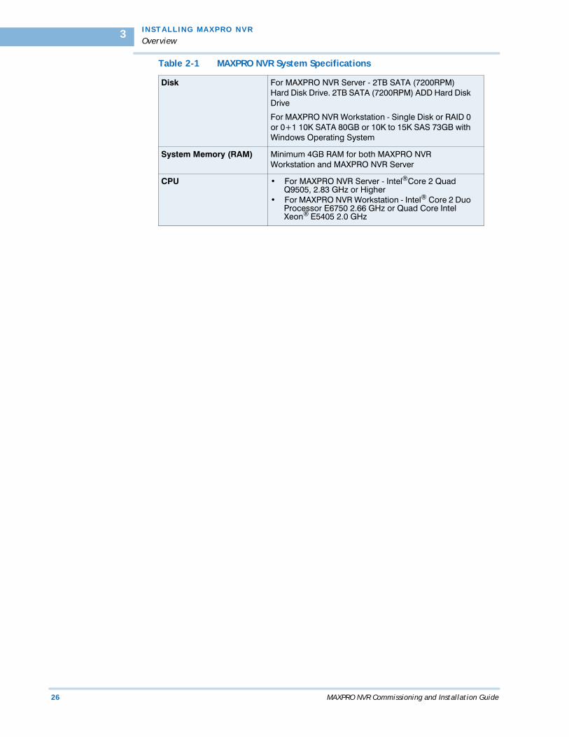
Table 2-1 MAXPRO NVR System Specifications
Operating System • For MAXPRO NVR Server - Microsoft Windows® 7 Professional (32-bit and 64-bit), Microsoft Windows® 2008 Server R2
• For MAXPRO NVR Client - Microsoft Windows® 7 Professional for MAXPRO NVR Workstation
Antivirus McAfee® VirusScan 8.8, or Symantec™ Antivirus V10
Monitor Resolution 1024x1024 pixels (resolution), 65K colors non-interlaced (color quality)
I N S T A L L I NG M A X P R O N V R
Overview
26 MAXPRO NVR Commissioning and Installation Guide
3
Disk For MAXPRO NVR Server - 2TB SATA (7200RPM) Hard Disk Drive. 2TB SATA (7200RPM) ADD Hard Disk Drive
For MAXPRO NVR Workstation - Single Disk or RAID 0 or 0+1 10K SATA 80GB or 10K to 15K SAS 73GB with Windows Operating System
System Memory (RAM) Minimum 4GB RAM for both MAXPRO NVR Workstation and MAXPRO NVR Server
CPU • For MAXPRO NVR Server - Intel®Core 2 Quad Q9505, 2.83 GHz or Higher
• For MAXPRO NVR Workstation - Intel® Core 2 Duo Processor E6750 2.66 GHz or Quad Core Intel Xeon® E5405 2.0 GHz
Table 2-1 MAXPRO NVR System Specifications

. .
. .
.
I N S T AL L I NG M A X P RO N V R
MAXPRO NVR Installation
MAXPRO NVR Commissioning and Installation Guide 27
. . . . . . . . . . . . . . . . . . . . . . . . . . . . . . . . . . . . . . . . . . . . . . . . . . . . . . . . . . .MAXPRO NVR INSTALLATION
To complete the MAXPRO NVR installation follow the procedures in these sections.
1. First, How to Install MAXPRO NVR
2. Choose the installation that best suits your requirements, and follow the appropriate steps.
• Full Installation• Client Installation
. . . . . . . . . . . . . . . . . . . . . . . . . . . . . . . . . . . . . . . . . . . . . . . . . . . . . . . . . . .HOW TO INSTALL MAXPRO NVR
To install MAXPRO NVR
1. Insert the MAXPRO NVR DVD in to the DVD drive. The setup runs automatically. If the setup does not run automatically, browse to the Setup folder on the DVD, and double-click Setup.exe. Figure 3-1 appears.
Figure 3-1 Welcome
2. Click Next. Figure 3-2 appears displaying the license agreement for the MAXPRO NVR.

I N S T A L L I NG M A X P R O N V R
How to Install MAXPRO NVR
28 MAXPRO NVR Commissioning and Installation Guide
3
Figure 3-2 License Agreement
3. Read the license agreement, and then click I accept the terms of the license agreement to accept the license agreement.
4. Click Next. Figure 3-3 appears.
Figure 3-3 Customer Information
5. Type your Registered To name.
6. Type your Company Name.
7. Click Next. Figure 3-4 appears.

. .
. .
.
I N S T AL L I NG M A X P RO N V R
How to Install MAXPRO NVR
MAXPRO NVR Commissioning and Installation Guide 29
Figure 3-4 Choose Destination Folder
8. Click Change if you want to change the destination folder, and then select the folder where MAXPRO NVR must be installed.
9. Click Next. Figure 3-5 appears.
Figure 3-5 Validation of User Credentials
10. Select your Domain Name/Host Name from the domains listed.
11. Type your Windows User Name.
12. Type your Windows Password.
13. Click Next. A message “ Enabling Auto Logon is not secure as the Password will be stored in the Registry. Do you want to continue” appears. Click Yes. Figure 3-6 appears.
I N S T A L L I NG M A X P R O N V R
How to Install MAXPRO NVR
30 MAXPRO NVR Commissioning and Installation Guide
3
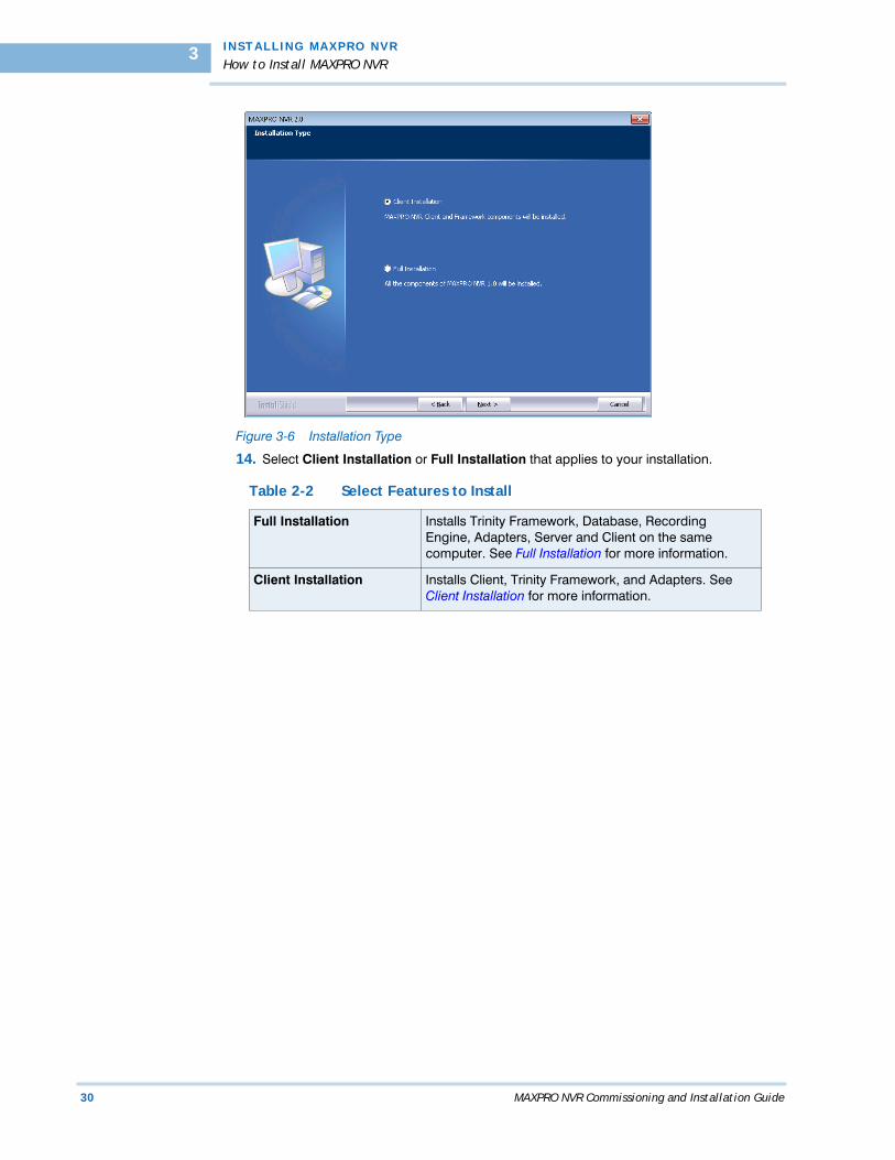
Figure 3-6 Installation Type
14. Select Client Installation or Full Installation that applies to your installation.
Table 2-2 Select Features to Install
Full Installation Installs Trinity Framework, Database, Recording Engine, Adapters, Server and Client on the same computer. See Full Installation for more information.
Client Installation Installs Client, Trinity Framework, and Adapters. See Client Installation for more information.

. .
. .
.
I N S T AL L I NG M A X P RO N V R
Full Installation
MAXPRO NVR Commissioning and Installation Guide 31
. . . . . . . . . . . . . . . . . . . . . . . . . . . . . . . . . . . . . . . . . . . . . . . . . . . . . . . . . . .FULL INSTALLATION
Full installation can be selected when you are operating MAXPRO NVR from a location that consists of adapters, recording engine, and database server. Full installation requires computers with performance configuration.
Full installation can be done to:
• Server and Client.To perform full installation
1. Perform steps 1 through 14 of How to Install MAXPRO NVR, select Full Installation in Figure 3-6, and then click Next. Figure 3-7 appears.
Figure 3-7 Database Server Login
2. Click Browse, and then select any existing SQL database. You can select the existing SQL database on the same network. If you do not want to select an existing database, proceed to step 3.
3. Select Connect using option as Windows authentication or SQL Server authentication. Type the Login ID and Password if you select SQL Sever authentication.
Note: If you are installing MAXPRO NVR on a new computer that does not have SQL Server 2008 Express installed, you are prompted to install it. Follow the on-screen instructions to complete the installation.
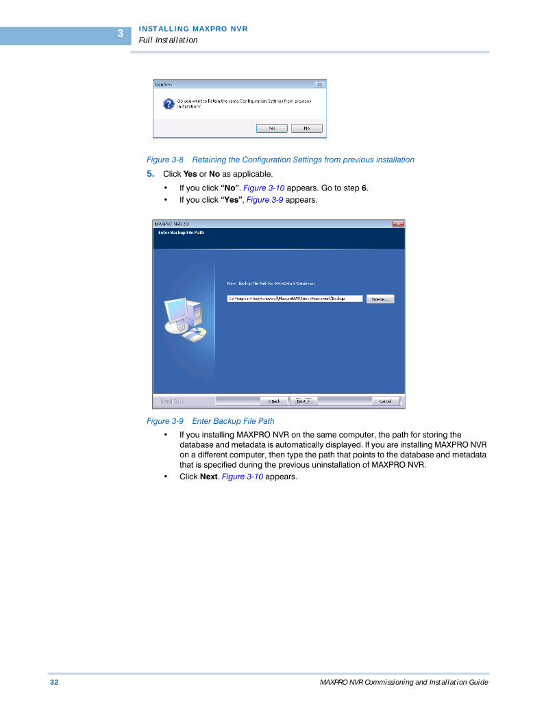
4. Click Next. The message “Do you want to retain the same Configuration Settings from previous installation” appears as shown in Figure 3-8 appears.
I N S T A L L I NG M A X P R O N V R
Full Installation
32 MAXPRO NVR Commissioning and Installation Guide
3
Figure 3-8 Retaining the Configuration Settings from previous installation
5. Click Yes or No as applicable.
• If you click “No”. Figure 3-10 appears. Go to step 6.• If you click “Yes”, Figure 3-9 appears.
Figure 3-9 Enter Backup File Path
• If you installing MAXPRO NVR on the same computer, the path for storing the database and metadata is automatically displayed. If you are installing MAXPRO NVR on a different computer, then type the path that points to the database and metadata that is specified during the previous uninstallation of MAXPRO NVR.
• Click Next. Figure 3-10 appears.

. .
. .
.
I N S T AL L I NG M A X P RO N V R
Full Installation
MAXPRO NVR Commissioning and Installation Guide 33
Figure 3-10 Choose Trinity Database Location
6. The default path for Trinity database is displayed. Click Browse to select a different path for the Trinity database.
7. Click Next. The message “TrinityDatabase file already exists. Do you want to retain the database” appears. This message appears only if you have opted to retain the database and not metadata during the previous uninstallation.
• If you click “Yes”, the existing Trinity Database is retained for this installation. Figure 3-12 appears. Go to step 8.
• If you click “No”, the existing trinity database is not retained for this installation. Figure 3-11 appears.
Figure 3-11 Choose Clip Directory Location
• The default path for saving the recorded video is displayed. Click Browse to select a different path for storing the recorded video.

I N S T A L L I NG M A X P R O N V R
Full Installation
34 MAXPRO NVR Commissioning and Installation Guide
3
Note: Select a different drive for saving the recorded video other than the Operating System drive.
• Click Next. Figure 3-12 appears.
Figure 3-12 Start Copying Files
8. If you want to review or change any settings click Back, otherwise click Next. The setup status of various components appears. Figure 3-13 appears after MAXPRO NVR is successfully installed.
Figure 3-13 InstallShield Wizard Complete
9. Click Finish. You are prompted to reboot the computer to complete the MAXPRO NVR installation.
10. Click OK. The computer reboots.
. .
. .
.
I N S T AL L I NG M A X P RO N V R
Client Installation
MAXPRO NVR Commissioning and Installation Guide 35
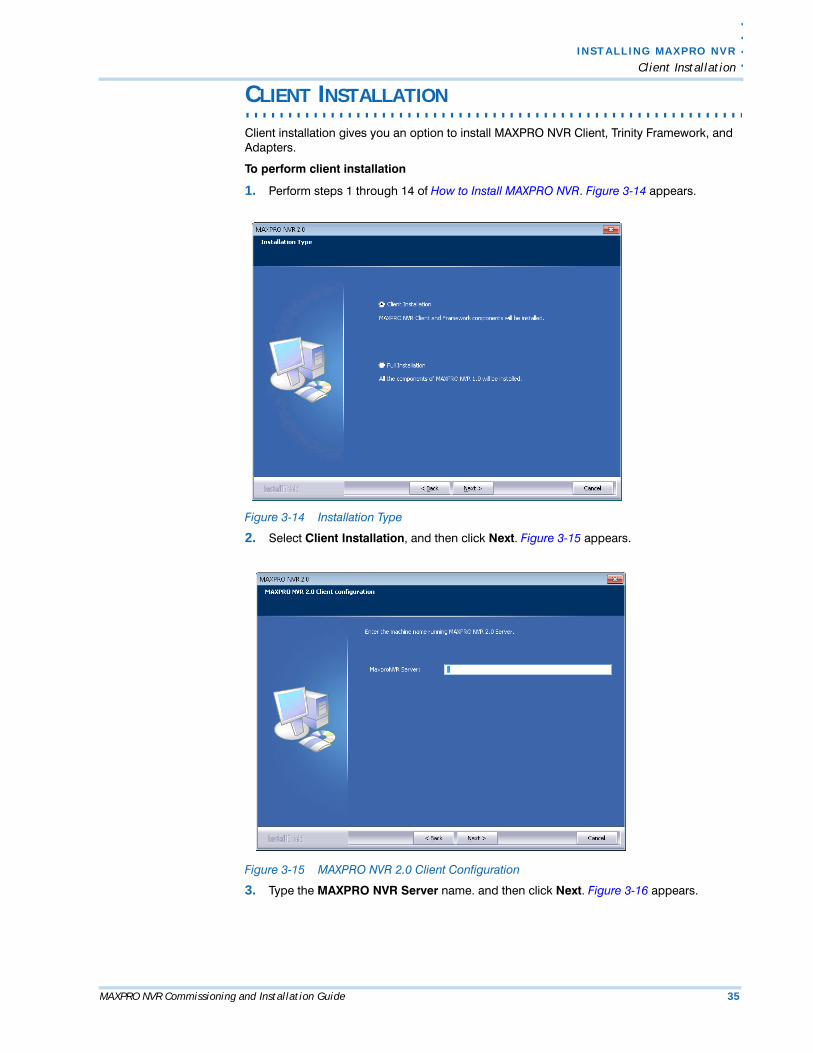
. . . . . . . . . . . . . . . . . . . . . . . . . . . . . . . . . . . . . . . . . . . . . . . . . . . . . . . . . . .CLIENT INSTALLATION
Client installation gives you an option to install MAXPRO NVR Client, Trinity Framework, and Adapters.
To perform client installation
1. Perform steps 1 through 14 of How to Install MAXPRO NVR. Figure 3-14 appears.
Figure 3-14 Installation Type
2. Select Client Installation, and then click Next. Figure 3-15 appears.
Figure 3-15 MAXPRO NVR 2.0 Client Configuration
3. Type the MAXPRO NVR Server name. and then click Next. Figure 3-16 appears.

I N S T A L L I NG M A X P R O N V R
Client Installation
36 MAXPRO NVR Commissioning and Installation Guide
3
Note: If you do not know the server name or if the server is not accessible, then type the local host name.
Figure 3-16 Start Copying Files
4. If you want to review or change any settings click Back, otherwise click Next The setup status of various components appears. Figure 3-17 appears after MAXPRO NVR is successfully installed.
Figure 3-17 InstallShield Wizard Complete
5. Click Finish. You are prompted to reboot the computer to complete the MAXPRO NVR installation.
6. Click OK. Your computer reboots to complete the installation procedure.
. .
. .
.
I N S T AL L I NG M A X P RO N V R
Upgrading MAXPRO NVR
MAXPRO NVR Commissioning and Installation Guide 37
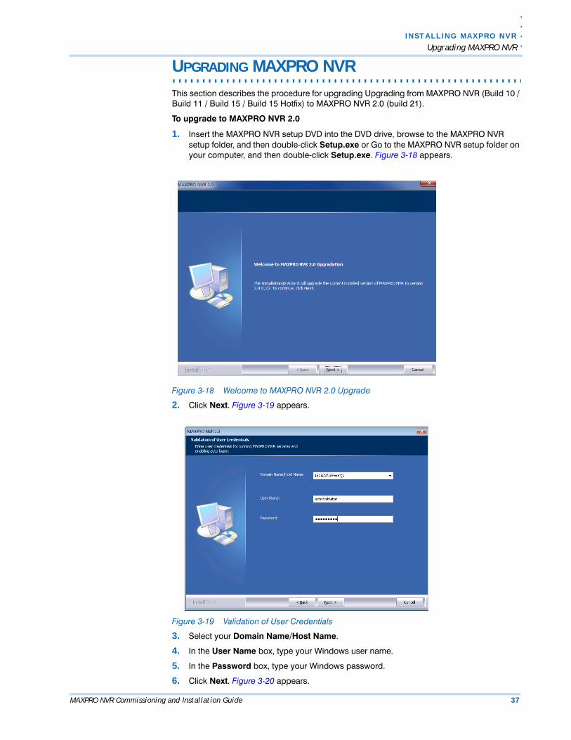
. . . . . . . . . . . . . . . . . . . . . . . . . . . . . . . . . . . . . . . . . . . . . . . . . . . . . . . . . . .UPGRADING MAXPRO NVR
This section describes the procedure for upgrading Upgrading from MAXPRO NVR (Build 10 / Build 11 / Build 15 / Build 15 Hotfix) to MAXPRO NVR 2.0 (build 21).
To upgrade to MAXPRO NVR 2.0
1. Insert the MAXPRO NVR setup DVD into the DVD drive, browse to the MAXPRO NVR setup folder, and then double-click Setup.exe or Go to the MAXPRO NVR setup folder on your computer, and then double-click Setup.exe. Figure 3-18 appears.
Figure 3-18 Welcome to MAXPRO NVR 2.0 Upgrade
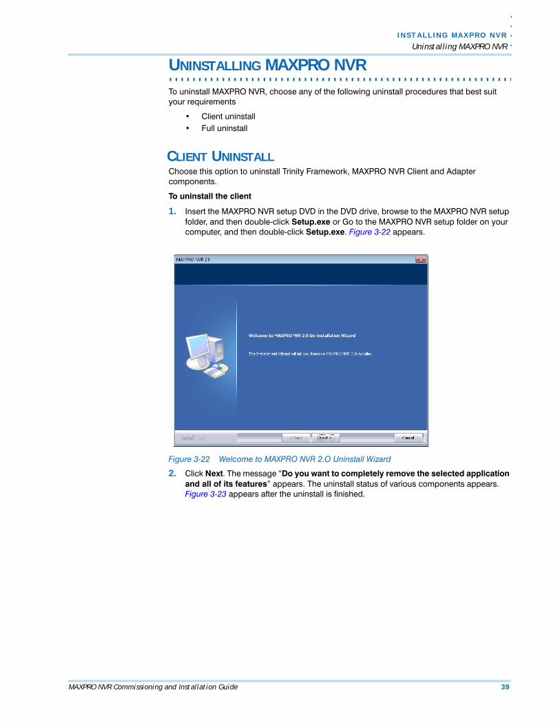
2. Click Next. Figure 3-19 appears.
Figure 3-19 Validation of User Credentials
3. Select your Domain Name/Host Name.
4. In the User Name box, type your Windows user name.
5. In the Password box, type your Windows password.
6. Click Next. Figure 3-20 appears.

I N S T A L L I NG M A X P R O N V R
Upgrading MAXPRO NVR
38 MAXPRO NVR Commissioning and Installation Guide
3
Figure 3-20 Start Copying Files
7. Click Next. The upgrade status of various components appears. Figure 3-21 appears after the upgrade is finished.
Figure 3-21 Upgrade Complete
8. Click Finish. You are prompted to reboot the computer to complete the MAXPRO NVR upgrade.
9. Click OK. The computer reboots.
. .
. .
.
I N S T AL L I NG M A X P RO N V R
Uninstalling MAXPRO NVR
MAXPRO NVR Commissioning and Installation Guide 39
. . . . . . . . . . . . . . . . . . . . . . . . . . . . . . . . . . . . . . . . . . . . . . . . . . . . . . . . . . .UNINSTALLING MAXPRO NVR
To uninstall MAXPRO NVR, choose any of the following uninstall procedures that best suit your requirements
• Client uninstall• Full uninstall
CLIENT UNINSTALLChoose this option to uninstall Trinity Framework, MAXPRO NVR Client and Adapter components.
To uninstall the client
1. Insert the MAXPRO NVR setup DVD in the DVD drive, browse to the MAXPRO NVR setup folder, and then double-click Setup.exe or Go to the MAXPRO NVR setup folder on your computer, and then double-click Setup.exe. Figure 3-22 appears.
Figure 3-22 Welcome to MAXPRO NVR 2.O Uninstall Wizard
2. Click Next. The message “Do you want to completely remove the selected application and all of its features” appears. The uninstall status of various components appears. Figure 3-23 appears after the uninstall is finished.
I N S T A L L I NG M A X P R O N V R
Uninstalling MAXPRO NVR
40 MAXPRO NVR Commissioning and Installation Guide
3
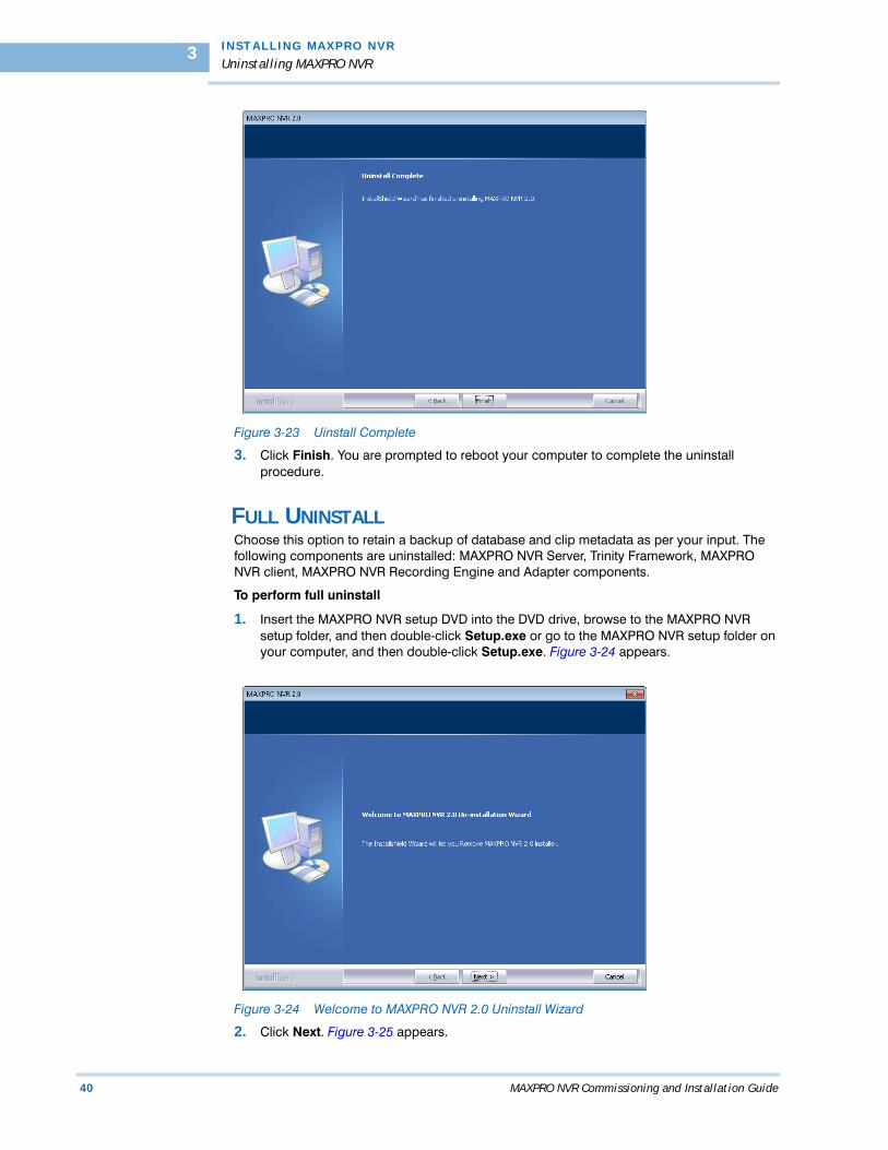
Figure 3-23 Uinstall Complete
3. Click Finish. You are prompted to reboot your computer to complete the uninstall procedure.
FULL UNINSTALLChoose this option to retain a backup of database and clip metadata as per your input. The following components are uninstalled: MAXPRO NVR Server, Trinity Framework, MAXPRO NVR client, MAXPRO NVR Recording Engine and Adapter components.
To perform full uninstall
1. Insert the MAXPRO NVR setup DVD into the DVD drive, browse to the MAXPRO NVR setup folder, and then double-click Setup.exe or go to the MAXPRO NVR setup folder on your computer, and then double-click Setup.exe. Figure 3-24 appears.
Figure 3-24 Welcome to MAXPRO NVR 2.0 Uninstall Wizard
2. Click Next. Figure 3-25 appears.

. .
. .
.
I N S T AL L I NG M A X P RO N V R
Uninstalling MAXPRO NVR
MAXPRO NVR Commissioning and Installation Guide 41
Figure 3-25 Restoring Trinity Database
3. Click Yes or No as applicable.
• If you click “Yes” and then click Next, the database is retained for future installations of MAXPRO NVR. Figure 3-26 appears. Go to step 4.
• If you click “No” and then click Yes to confirm deleting the Trinity database. The database is deleted. The uninstall status of various components appears. Figure appears after the uinstall is finished. Go to step 7.
Figure 3-26 Retaining Clip Metadata
4. Click Yes or No as applicable.
• If you click “Yes” and then click Next, the clip metadata path is retained for future installations of MAXPRO NVR. Figure 3-27 appears. Go to step 5.
• If you click “No” and then click Next, the clip metadata path is deleted. The uninstall status of various components appears. Figure 3-28 appears. Go to step 7.

I N S T A L L I NG M A X P R O N V R
Uninstalling MAXPRO NVR
42 MAXPRO NVR Commissioning and Installation Guide
3
Figure 3-27 Choose Backup File Location
5. The default backup location for storing the database and metadata is displayed. Click Browse to specify a new path.
6. Click Next. The uninstall status of various components appears. Figure 3-28 appears. Go to step 7.
Figure 3-28 Uinstall Complete
7. Click Finish. You are prompted to reboot your computer and OK to complete the uninstall procedure.

MAXPRO NVR Commissioning and Installation Guide 43
4. . . . .
. . . . . . . . . . . . . . . . . . . . . . . . . . . . . . . . . . .CONFIGURING MAXPRO NVR
. . . . . . . . . . . . . . . . . . . . . . . . . . . . . . . . . . . . . . . . . . . . . . . . . . . . . . . . . . .OVERVIEW
Configuring MAXPRO NVR involves setting up the system to perform video surveillance and IP recording operations. This is the most important phase for commissioning MAXPRO NVR system as it involves setting up the MAXPRO NVR IP address, organizing devices, users, and roles.
BEFORE YOU BEGIN• Ensure that you have completed MAXPRO NVR server and client hardware setup
and software installation.• Configure the firewall settings as mentioned in the Firewall Settings section.

C O N F I G U R I N G M A X P R O N V R
Firewall Settings
44 MAXPRO NVR Commissioning and Installation Guide
4
. . . . . . . . . . . . . . . . . . . . . . . . . . . . . . . . . . . . . . . . . . . . . . . . . . . . . . . . . . .FIREWALL SETTINGS
Caution: The Firewall settings are pre-configured for boxed solutions – MAXPRO NVR XE and MAXPRO NVR SE. For MAXPRO NVR Software-Only solution, the Firewall settings mentioned in the following sections must be performed after you install the MAXPRO NVR software.
Note: The procedure in this section assumes you are knowledgeable about Windows firewall rules. Please consult your network administrator for assistance if any in this regard.
You need to configure inbound and outbound firewall rules for a number of ports and application executable files. See the following tables while following the procedure that follows.
Table 4-1 Firewall Settings Checklist
Port Rules
Description Port Port Number
Server/Controller Operations TCP 20007
Controller TCP 26026
DNS Server TCP 53
Scheduler Operations TCP 20010
DCOM Services TCP 135
File and Print Sharing TCP 139, 445, 137, 138
Client and Server Communication TCP 80
NEOServer TCP 10000
Rendering Connection TCP 20009
Application Rules
Description Executable File Name Directory Path
NEOStorageExtWDService NeoStorageMonitor.exe C:\Program Files\Honeywell\MaxproNVR\TrinityFramework\bin\REIPEngine
NEOStorageServer NeoStorageEngine.exe
. .
. .
.
C O N F I G U R I NG M A X P R O N V R
Firewall Settings
MAXPRO NVR Commissioning and Installation Guide 45
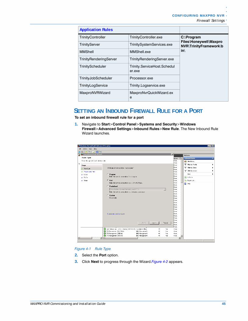
SETTING AN INBOUND FIREWALL RULE FOR A PORTTo set an inbound firewall rule for a port
1. Navigate to Start>Control Panel>Systems and Security>Windows Firewall>Advanced Settings>Inbound Rules>New Rule. The New Inbound Rule Wizard launches.
Figure 4-1 Rule Type
2. Select the Port option.
3. Click Next to progress through the Wizard.Figure 4-2 appears.
TrinityController TrinityController.exe C:\Program Files\Honeywell\MaxproNVR\TrinityFramework\bin\
TrinityServer TrinitySystemServices.exe
MMShell MMShell.exe
TrinityRenderingServer TrinityRenderingServer.exe
TrinityScheduler Trinity.ServiceHost.Scheduler.exe
TrinityJobScheduler Processor.exe
TrinityLogService Trinity.Logservice.exe
MaxproNVRWizard MaxproNvrQuickWizard.exe
Application Rules
C O N F I G U R I N G M A X P R O N V R
Firewall Settings
46 MAXPRO NVR Commissioning and Installation Guide
4
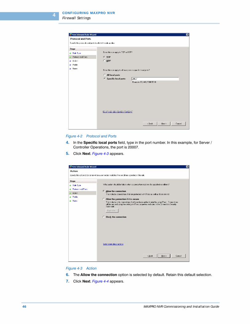
Figure 4-2 Protocol and Ports
4. In the Specific local ports field, type in the port number. In this example, for Server / Controller Operations, the port is 20007.
5. Click Next. Figure 4-3 appears.
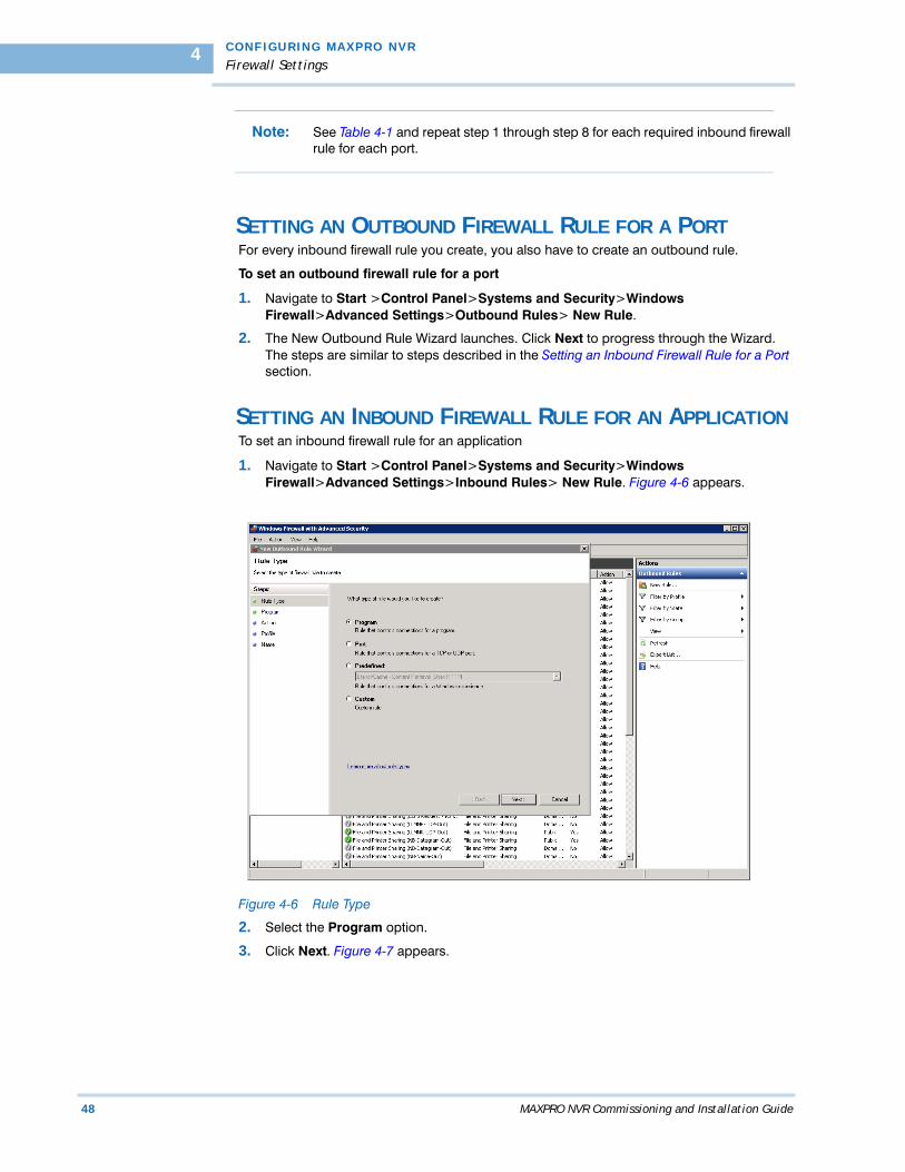
Figure 4-3 Action
6. The Allow the connection option is selected by default. Retain this default selection.
7. Click Next. Figure 4-4 appears.

. .
. .
.
C O N F I G U R I NG M A X P R O N V R
Firewall Settings
MAXPRO NVR Commissioning and Installation Guide 47
Figure 4-4 Profile
8. The Domain, Private, and Public check boxes are selected by default. Retain these default selections.
9. Click Next. Figure 4-5 appears.
Figure 4-5 Name
10. In the Name field, type the appropriate name from Table 4-1. In this example it is Server / Controller Operations (with a space before and after the slash). The Description field is optional.
11. Click Finish.
C O N F I G U R I N G M A X P R O N V R
Firewall Settings
48 MAXPRO NVR Commissioning and Installation Guide
4
Note: See Table 4-1 and repeat step 1 through step 8 for each required inbound firewall rule for each port.
SETTING AN OUTBOUND FIREWALL RULE FOR A PORTFor every inbound firewall rule you create, you also have to create an outbound rule.
To set an outbound firewall rule for a port
1. Navigate to Start >Control Panel>Systems and Security>Windows Firewall>Advanced Settings>Outbound Rules> New Rule.
2. The New Outbound Rule Wizard launches. Click Next to progress through the Wizard. The steps are similar to steps described in the Setting an Inbound Firewall Rule for a Port section.
SETTING AN INBOUND FIREWALL RULE FOR AN APPLICATIONTo set an inbound firewall rule for an application
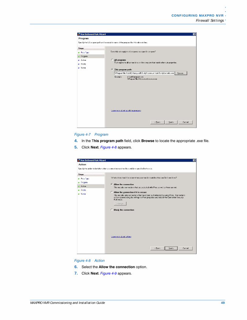
1. Navigate to Start >Control Panel>Systems and Security>Windows Firewall>Advanced Settings>Inbound Rules> New Rule. Figure 4-6 appears.
Figure 4-6 Rule Type
2. Select the Program option.
3. Click Next. Figure 4-7 appears.
. .
. .
.
C O N F I G U R I NG M A X P R O N V R
Firewall Settings
MAXPRO NVR Commissioning and Installation Guide 49
Figure 4-7 Program
4. In the This program path field, click Browse to locate the appropriate .exe file.
5. Click Next. Figure 4-8 appears.
Figure 4-8 Action
6. Select the Allow the connection option.
7. Click Next. Figure 4-9 appears.
C O N F I G U R I N G M A X P R O N V R
Firewall Settings
50 MAXPRO NVR Commissioning and Installation Guide
4
Figure 4-9 Profile
8. The Domain, Private, and Public check boxes are selected by default. Retain these default selections.
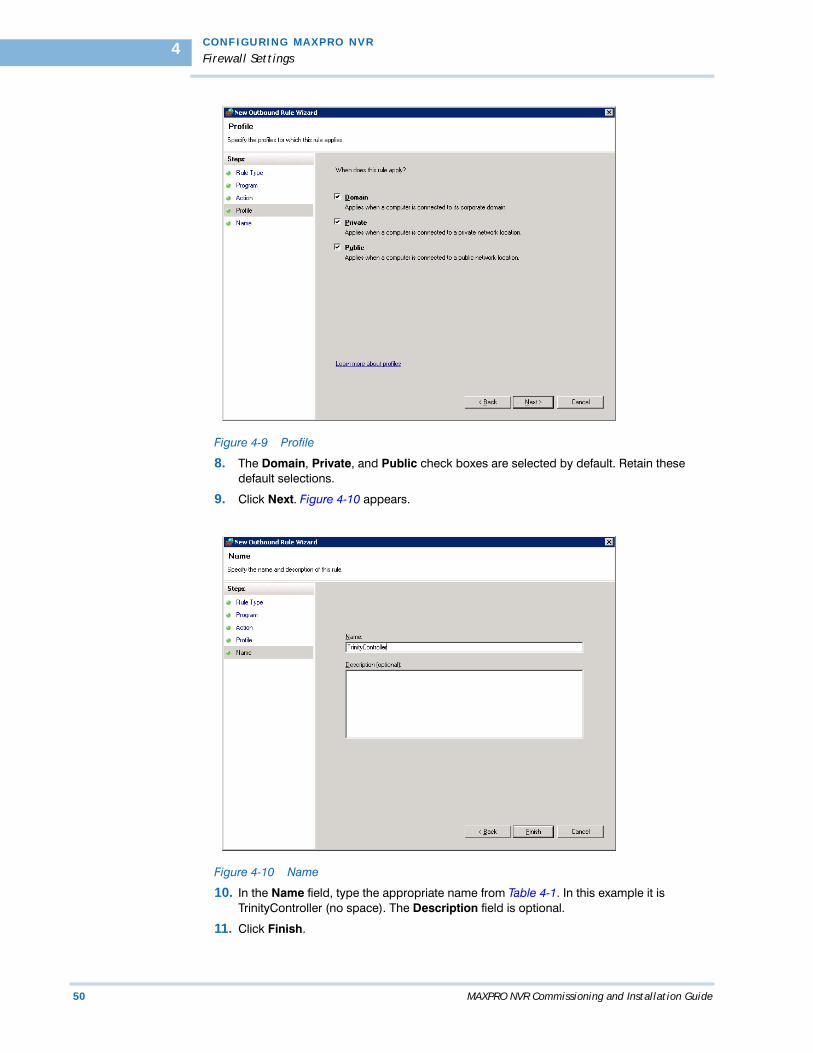
9. Click Next. Figure 4-10 appears.
Figure 4-10 Name
10. In the Name field, type the appropriate name from Table 4-1. In this example it is TrinityController (no space). The Description field is optional.
11. Click Finish.

. .
. .
.
C O N F I G U R I NG M A X P R O N V R
Firewall Settings
MAXPRO NVR Commissioning and Installation Guide 51
Note: See Table 4-1 and repeat step 1 through step 8 for each required inbound firewall rule for each application.
SETTING AN OUTBOUND FIREWALL RULE FOR AN APPLICATIONFor every inbound firewall rule you create, you also have to create an outbound rule.
To set an outbound firewall rule for an application
1. Navigate to Start >Control Panel>Systems and Security>Windows Firewall>Advanced Settings>Outbound Rules> New Rule.
2. The New Outbound Rule Wizard launches. Click Next to progress through the Wizard. The steps are similar to steps described in the Setting an Inbound Firewall Rule for an Application section.
C O N F I G U R I N G M A X P R O N V R
Configuring MAXPRO NVR
52 MAXPRO NVR Commissioning and Installation Guide
4
. . . . . . . . . . . . . . . . . . . . . . . . . . . . . . . . . . . . . . . . . . . . . . . . . . . . . . . . . . .CONFIGURING MAXPRO NVR
The configuration process involves the following tasks.
• Configuring the system level settings• Configuring the disk management settings• Configuring the cameras• Configuring the schedule based recording for cameras• Performing user administration.
Note: An easy way to configure the MAXPRO NVR system is using the MAXPRO NVR Wizard, which is a 3-step procedure to live video. Refer MAXPRO NVR Operator’s Guide for more information.
To go to the Configurator tab
1. Double-click the icon on your desktop. The MAXPRO NVR Log On dialog box
appears.
Caution: Only on the Honeywell provided systems, a default Windows user, “Administrator” and password “Password1” is already configured and hence you are automatically logged in.
2. Type the Username. The default user name is “admin”.
3. Type your Password. The default password is “trinity”.
Note: Select the Windows Logged-In User check box for logging on using the Windows user name and password. If the Windows Logged-In User check box is cleared, the MAXPRO NVR user name and password is used for authentication. If there is no profile set as default, then select the Profile corresponding to the MAXPRO NVR server to which you want to connect.
Note: Set profiles if you have multiple MAXPRO NVR units and use the drop-down to choose which NVR unit you would like to connect to.
4. Select the Display Video on Alarm check box to display the viewer as an alarm monitor.
5. Press Enter or click the icon. The Viewer screen appears by default.
6. Click the Configurator tab to open the Configurator screen.The System page opens by default.

. .
. .
.
C O N F I G U R I NG M A X P R O N V R
Configuring MAXPRO NVR
MAXPRO NVR Commissioning and Installation Guide 53
CONFIGURING THE SYSTEM SETTINGS FOR MAXPRO NVR The System settings help in configuring the following:
• General System Settings - enable configuring the device name, device description, and device address for MAXPRO NVR.
• Recording Settings - enable configuring the times associated to event and user based recording.
• Email Settings - enable configuring the SMTP server settings for e-mail communication of events.
• Holiday/Exception Settings for Schedules - enable configuring the holidays and exceptions for schedule based recording.
To configure the system settings
• Click the Configurator tab. The System page appears by default.
CONFIGURING DISK MANAGEMENT SETTINGSThe Disk Management settings help you to configure the disk settings for saving the recorded video.
To configure the disk management settings
1. Click the Configurator tab. The System page appears by default.
2. Click the Disk tab to open the Disk Management page.
CONFIGURING THE CAMERASYou can configure and add cameras using the Camera tab.
To configure the cameras
1. Click the Configurator tab. The System page appears by default.
2. Click the Camera tab to open the Camera page.
CONFIGURING SCHEDULE BASED RECORDING FOR CAMERASYou can create schedules for camera(s) to record video at recurring intervals for continuous recording or event based recording (for example, motion event). There are four default schedules: 24 x 7, Weekday, DayTime, NightTime.
To configure schedules
1. Click the Configurator tab. The System page appears by default.
2. Click the Schedule tab to open the Schedule page.
PERFORMING USER ADMINISTRATIONA user in MAXPRO NVR is responsible for performing various operations like viewing video, reporting alarms, and other video surveillance tasks. You can create two types of users in MAXPRO NVR.
System Local User
A system local user can access only MAXPRO NVR. This user may not have access to a client workstation.
Windows User
A windows user can access client workstation and also MAXPRO NVR.
Users and Roles
Roles are provided to a user. These roles comprise in them a set of privileges. When a user is associated to a role, the privileges that are available for the role are also assigned to the user.

C O N F I G U R I N G M A X P R O N V R
Configuring MAXPRO NVR
54 MAXPRO NVR Commissioning and Installation Guide
4
The “admin” User
The first time MAXPRO NVR is installed, a default user named “admin” is created. The “admin” user is assigned the role “NVRAdministrator”. Only user with “NVRAdministrator” privilege can add new users, assign roles to the added users, add or modify the privileges to the users, and perform various configurations in MAXPRO NVR.
To perform user administration
1. Click the Configurator tab. The System page appears by default.
2. Click the User tab to open the User page.

MAXPRO NVR Commissioning and Installation Guide 55
5. . . . .
. . . . . . . . . . . . . . . . . . . . . . . . . . . . . . . . . . .VERIFYING THE CONFIGURATION
. . . . . . . . . . . . . . . . . . . . . . . . . . . . . . . . . . . . . . . . . . . . . . . . . . . . . . . . . . .OVERVIEW
Verifying the configuration of the MAXPRO NVR is the final phase in the commissioning process. In this phase, you need to verify the working of the MAXPRO NVR.
BEFORE YOU BEGINEnsure that the configuration of MAXPRO NVR is complete.
ACTIVITIES TO PERFORM IN THIS PHASE In this phase, using the MAXPRO NVR user interface, check for the following one after the other.
• Connection with the MAXPRO NVR sever (logging on)
• Camera listing in the devices window
• Live video display from cameras
• Playback of recorded video
• Inserting comments and marking the point of interest using the bookmark feature in Timeline window
• Playback of loop (mark in and mark out feature) in Timeline window
• Panning, tilting, and zooming functions
• Acknowledgement of alarms and clearing of alarms
• Image creation
• Clip creation
• Video from the surrounding cameras (video pursuit or surrounding cameras feature in MAXPRO NVR)
• Saving the salvo layout using the salvo view feature
• Searching recorded video MAXPRO NVR
• Generating and viewing the event and operator log report
VE R IFY ING TH E CONF IG URA T ION
Checking the Connection with the MAXPRO NVR Server
56 MAXPRO NVR Commissioning and Installation Guide
5
CHECKING THE CONNECTION WITH THE MAXPRO
. . . . . . . . . . . . . . . . . . . . . . . . . . . . . . . . . . . . . . . . . . . . . . . . . . . . . . . . . . .NVR SERVER
The MAXPRO NVR server addresses are stored in profiles. You can save the address of each server in profiles from the Log On dialog box that appears when you start MAXPRO NVR.
To connect to a MAXPRO NVR server from the client computer
1. In the Username box, type the user name. The default user name is “admin”.
2. In the Password box, type the password. The default password f is “trinity”.
3. In the Profile box, select the profile in which the server address is saved.
4. Press Enter or click the icon. The Viewer Screen appears.
You can set a profile as the default profile. When a profile is set as default, you need not select the profile each time you log on to MAXPRO NVR. You can also modify and delete profiles.
Note: Refer to the MAXPRO NVR Operator’s Guide for more information on how to save server addresses in profiles, how to set a profile as default profile, and how to modify and delete the profiles.
. .
. .
.
VE R I F Y I N G T H E C O N F I G U RA T I O N
Checking the Device Listing in the Devices Window
MAXPRO NVR Commissioning and Installation Guide 57
CHECKING THE DEVICE LISTING IN THE DEVICES
. . . . . . . . . . . . . . . . . . . . . . . . . . . . . . . . . . . . . . . . . . . . . . . . . . . . . . . . . . .WINDOW
By default, the Viewer tab is selected when you log on to MAXPRO NVR. The Devices window in the Viewer tab lists the Honeywell IP cameras connected to and discovered by MAXPRO NVR.
Note: Refer to the MAXPRO NVR Operator’s Guide for more information on the Device window.

VE R IFY ING TH E CONF IG URA T ION
Checking the Acknowledgement and Clearing of Alarms
58 MAXPRO NVR Commissioning and Installation Guide
5
CHECKING THE ACKNOWLEDGEMENT AND CLEARING
. . . . . . . . . . . . . . . . . . . . . . . . . . . . . . . . . . . . . . . . . . . . . . . . . . . . . . . . . . .OF ALARMS
Clicking the Alarms tab next to the Device tab opens the Alarms window that lists all the alarms in a floating window. You can acknowledge and clear the alarms.
Alarms notify the occurrence of events to the operators. You can configure alarms to be triggered when events such as recorder disk space nearing full, motion detection, and others happen. The events that trigger an alarm can be selected while configuring the recorders, cameras, and switchers. The events can be associated to event groups.
Each alarm goes through the following states.
New or Unacknowledged
When an alarm is triggered it appears in the Alarm window. You can click the Alarm tab to view the Alarm window. The state of the alarm after it is triggered is referred to as unacknowledged. You can view the list of all the unacknowledged alarms in a table in the Alarm window.
Note: Refer to the MAXPRO NVR Operator’s Guide for more information on the Alarms.

. .
. .
.
VE R I F Y I N G T H E C O N F I G U RA T I O N
Checking the Live Video from Cameras
MAXPRO NVR Commissioning and Installation Guide 59
. . . . . . . . . . . . . . . . . . . . . . . . . . . . . . . . . . . . . . . . . . . . . . . . . . . . . . . . . . .CHECKING THE LIVE VIDEO FROM CAMERAS
To ensure that all the cameras are connected and functioning properly, you need to check for live video from them.
To select the cameras and view live video
• Double-click a camera in the Devices window. You can also drag a camera to a panel in the salvo layout. The panel starts displaying live video.
You can select multiple cameras and view live video in different panels of the salvo layout.
Note: Refer to the MAXPRO NVR Operator’s Guide for more information on how to view live video from cameras.
VE R IFY ING TH E CONF IG URA T ION
Checking the Playback of Recorded Video
60 MAXPRO NVR Commissioning and Installation Guide
5
. . . . . . . . . . . . . . . . . . . . . . . . . . . . . . . . . . . . . . . . . . . . . . . . . . . . . . . . . . .CHECKING THE PLAYBACK OF RECORDED VIDEO
To playback video, the recording from the camera must be available and the recording settings for the camera must be configured. Recorded video can be played from the Timeline window.
The following operations can be performed on the recorded video.
• Playing recorded video using the timeline• Playing recorded video using Mark In and Mark Out points in timeline• Marking points of interest in the timeline using bookmarks
Note: Refer to the MAXPRO NVR Operator’s Guide for more information on how to configure the recording settings for the cameras connected to MAXPRO NVR.

. .
. .
.
VE R I F Y I N G T H E C O N F I G U RA T I O N
Checking the Panning, Tilting, and Zooming
MAXPRO NVR Commissioning and Installation Guide 61
. . . . . . . . . . . . . . . . . . . . . . . . . . . . . . . . . . . . . . . . . . . . . . . . . . . . . . . . . . .CHECKING THE PANNING, TILTING, AND ZOOMING
Using the digital PTZ feature in MAXPRO NVR, you can perform panning and tilting on live and recorded video and clips. The digital PTZ feature when enabled allows you to perform panning and tilting on the video display that is zoomed or enlarged in a panel.
Note: Refer to the MAXPRO NVR Operator’s Guide for more information on PTZ.
VE R IFY ING TH E CONF IG URA T ION
Checking the Creation of Images
62 MAXPRO NVR Commissioning and Installation Guide
5
. . . . . . . . . . . . . . . . . . . . . . . . . . . . . . . . . . . . . . . . . . . . . . . . . . . . . . . . . . .CHECKING THE CREATION OF IMAGES
A frame of video displayed in the panel can be saved as an image. The image can be saved in Bitmapped Graphics (BMP), Joint Photographic Experts Group (JPG) format, Portable Graphics format (PNG), and Graphics Interchange Format (GIF).
Only the images saved in the ImagesAndClips folder at the location in the hard drive in which MAXPRO NVR files are installed can be viewed in the Image/ Clip window.
You can double-click the image view option in the site window to view images on the salvo layout. You can view the images in the form of thumbnails or filmstrip. You can also select the image size large, medium, and small as per the requirement.
For example, X:\ProgramFiles\Honeywell\TrinityFramework\ImagesAndClips. Here, X: is the hard drive.
Note: Refer to the MAXPRO NVR Operator’s Guide for more information on creating the images.

. .
. .
.
VE R I F Y I N G T H E C O N F I G U RA T I O N
Checking the Creation of Clips
MAXPRO NVR Commissioning and Installation Guide 63
. . . . . . . . . . . . . . . . . . . . . . . . . . . . . . . . . . . . . . . . . . . . . . . . . . . . . . . . . . .CHECKING THE CREATION OF CLIPS
You can create clips from recorded video. These clips can be saved with digital signatures. Digital signatures ensure authenticity of clips. Digital signatures are primarily used to authenticate videos that are produced in courts as evidence. A digital signature generates a unique string for the clip using algorithms recommended by the W3C. The World Wide Web Consortium (W3C) is an international consortium where member organizations, a full-time staff, and the public work together to develop Web standards. If the video in the clip is modified, a verification check for the unique string fails indicating that the content is tampered. When a clip is saved with the digital signature, a package file with the .PKG extension is created to save the clip.
Note: Refer to the MAXPRO NVR Operator’s Guide for more information on creating clips.
VE R IFY ING TH E CONF IG URA T ION
Checking the Salvo View Feature
64 MAXPRO NVR Commissioning and Installation Guide
5
. . . . . . . . . . . . . . . . . . . . . . . . . . . . . . . . . . . . . . . . . . . . . . . . . . . . . . . . . . .CHECKING THE SALVO VIEW FEATURE
A salvo layout that is customized based on the preferences of the operators is referred to as a salvo view. Cameras and scan sequences that are selected frequently and the preferred salvo layout can be saved as a salvo view.
Note: Refer to the MAXPRO NVR Operator’s Guide for more information on how to create, select, and manage salvo views.

. .
. .
.
VE R I F Y I N G T H E C O N F I G U RA T I O N
Checking the Search for Recorded Video in MAXPRO NVR
MAXPRO NVR Commissioning and Installation Guide 65
CHECKING THE SEARCH FOR RECORDED VIDEO IN
. . . . . . . . . . . . . . . . . . . . . . . . . . . . . . . . . . . . . . . . . . . . . . . . . . . . . . . . . . .MAXPRO NVR
Operators can search for recorded video from cameras connected to MAXPRO NVR. The search results can be filtered based on conditions like video recorded today, yesterday, and others.
You can search for recorded video from the Search tab.
Note: Refer to the MAXPRO NVR Operator’s Guide for more information on how to search for recorded video, and how to play the search results.
VE R IFY ING TH E CONF IG URA T ION
Checking the Generation of Event History/ Operator Log Report
66 MAXPRO NVR Commissioning and Installation Guide
5
CHECKING THE GENERATION OF EVENT HISTORY/
. . . . . . . . . . . . . . . . . . . . . . . . . . . . . . . . . . . . . . . . . . . . . . . . . . . . . . . . . . .OPERATOR LOG REPORT
Two types of reports, namely event history report and operator log report, can be generated.
The event history report can be generated for cameras, monitors, and recorders. The event history report lists the events related to a device during a time period. For example, for a camera, you can generate the event history report to know the occurrence of events like enabling of camera motion detection, starting of background recording, and so on.
The operator log report can be generated to view the activities performed by users. The operator log report lists the activities performed by users during a time period. For example, creating clips, adding bookmarks.
You can generate reports from the Report tab.
Note: Refer to the MAXPRO NVR Operator’s Guide for more information on how to generate and view the reports.


Honeywell Systems (Head Office)2700 Blankenbaker Pkwy, Suite 150Louisville, KY 40299, USAwww.honeywellvideo.com +1.800.796.2288
Honeywell Security Europe/South AfricaAston Fields Road, Whitehouse Industrial EstateRuncorn, Cheshire, WA7 3DL, UKwww.honeywell.com/security/uk +44.01928.754028
Honeywell Systems Caribbean/Latin America9315 NW 112th Ave.Miami, FL 33178, USAwww.honeywellvideo.com +1.305.805.8188
Honeywell Systems PacificLevel 3, 2 Richardson PlaceNorth Ryde, NSW 2113, Australiawww.honeywellsecurity.com.au +61.2.9353.7000
Honeywell Systems Asia35F Tower A, City Center, 100 Zun Yi RoadShanghai 200051, Chinawww.asia.security.honeywell.com +86 21.5257.4568
Honeywell Security Middle East/N. AfricaPost Office Box 18530LOB Building 08, Office 199Jebel Ali, Dubai, United Arab Emirateswww.honeywell.com/security/me +971.04.881.5506
Honeywell Security Northern EuropeAmpèrestraat 411446 TR Purmerend, The Netherlandswww.honeywell.com/security/nl +31.299.410.200
Honeywell Security DeutschlandJohannes-Mauthe-Straße 14D-72458 Albstadt, Germanywww.honeywell.com/security/de +49 74 31 / 8 01-18 70
Honeywell Security FranceImmeuble LavoisierParc de Haute Technologie3-7 rue Georges Besse92160 Antony, Francewww.honeywell.com/security/fr +33.(0).1.40.96.20.50
Honeywell Security Italia SpAVia della Resistenza 53/5920090 BuccinascoMilan, Italywww.honeywell.com/security/it +39.02.4888.051
Honeywell Security EspañaAvenida de Italia, n° 7, 2a plantaC.T.C. Coslada28821 Coslada, Madrid, Spainwww.honeywell.com/security/es +34.902.667.800
© 2011 Honeywell International Inc. All rights reserved. No part of this publication may be reproduced by any means without written permission from Honeywell. The information in this publication is believed to be accurate in all respects. However, Honeywell cannot assume responsibility for any consequences resulting from the use thereof. The information contained herein is subject to change without notice. Revisions or new editions to this publication may be issued to incorporate such changes.
Document 800-09355V2 – 03/2012
www.honeywellvideo.com+1.800.796.CCTV (North America only)