maxum ii official product specifications - siemens ag · maxum pd pa ap maxum ii official product...
TRANSCRIPT
Maxum
PD PA APMaxum II Official Product Specifications
Brochure
These specifications supercede applicable information in previous manuals.
May 2018A5E03012338001 Rev04 ECO# DP5A00262128
Specifications Overview 1Maxum II Common Specifications 2
Airbath or Airless Oven 3
Modular Oven 4
Ovens 5Detectors and Associated Devices 6
Valve Specifications 7
Network Access Unit 8
Appendix - Change Log A
Legal informationWarning notice system
This manual contains notices you have to observe in order to ensure your personal safety, as well as to prevent damage to property. The notices referring to your personal safety are highlighted in the manual by a safety alert symbol, notices referring only to property damage have no safety alert symbol. These notices shown below are graded according to the degree of danger.
DANGERindicates that death or severe personal injury will result if proper precautions are not taken.
WARNINGindicates that death or severe personal injury may result if proper precautions are not taken.
CAUTIONindicates that minor personal injury can result if proper precautions are not taken.
NOTICEindicates that property damage can result if proper precautions are not taken.If more than one degree of danger is present, the warning notice representing the highest degree of danger will be used. A notice warning of injury to persons with a safety alert symbol may also include a warning relating to property damage.
Qualified PersonnelThe product/system described in this documentation may be operated only by personnel qualified for the specific task in accordance with the relevant documentation, in particular its warning notices and safety instructions. Qualified personnel are those who, based on their training and experience, are capable of identifying risks and avoiding potential hazards when working with these products/systems.
Proper use of Siemens productsNote the following:
WARNINGSiemens products may only be used for the applications described in the catalog and in the relevant technical documentation. If products and components from other manufacturers are used, these must be recommended or approved by Siemens. Proper transport, storage, installation, assembly, commissioning, operation and maintenance are required to ensure that the products operate safely and without any problems. The permissible ambient conditions must be complied with. The information in the relevant documentation must be observed.
TrademarksAll names identified by ® are registered trademarks of Siemens AG. The remaining trademarks in this publication may be trademarks whose use by third parties for their own purposes could violate the rights of the owner.
Disclaimer of LiabilityWe have reviewed the contents of this publication to ensure consistency with the hardware and software described. Since variance cannot be precluded entirely, we cannot guarantee full consistency. However, the information in this publication is reviewed regularly and any necessary corrections are included in subsequent editions.
Siemens AGDivision Process Industries and DrivesPostfach 48 4890026 NÜRNBERGGERMANY
Document order number: A5E03012338001Ⓟ 05/2018 Subject to change
Copyright © Siemens AG 2016 - 2018.All rights reserved
Table of contents
1 Specifications Overview...............................................................................................................................5
2 Maxum II Common Specifications................................................................................................................7
3 Airbath or Airless Oven...............................................................................................................................11
4 Modular Oven.............................................................................................................................................15
5 Ovens.........................................................................................................................................................19
6 Detectors and Associated Devices.............................................................................................................21
7 Valve Specifications...................................................................................................................................25
7.1 Model 50 Valve Specifications...............................................................................................25
7.2 Model 20 Valve Specifications...............................................................................................26
7.3 Model 20 High Temperature Valve Specifications.................................................................27
7.4 Model 11 Valve Specifications...............................................................................................27
7.5 Model 11 Low Dead Volume Valve (LDV) Specifications......................................................28
7.6 Siemens Liquid Injection Valve..............................................................................................28
7.7 Valco A4 C6UWE Valve Specifications..................................................................................29
8 Network Access Unit..................................................................................................................................31
A Appendix - Change Log..............................................................................................................................35
A.1 January 2018 Changes..........................................................................................................35
Maxum II Official Product SpecificationsBrochure, May 2018, A5E03012338001 Rev04 ECO# DP5A00262128 3

Table of contents
Maxum II Official Product Specifications4 Brochure, May 2018, A5E03012338001 Rev04 ECO# DP5A00262128
Specifications Overview 1The specifications in this document are provided to assist in product comparison and selection. See the product documentation for more details.
NoteSpecifications Are Application-Dependent
The specifications given in this document reflect the performance of the component when used in a Maxum II Gas Chromatograph as a typical system. Performance may vary between individual installations.
NoteSee Individual Documentation Package
Each analyzer is shipped with an Individual Documentation Package that includes drawings, specifications and certifications for the individual unit that supersede the information in this document.
Maxum II Official Product SpecificationsBrochure, May 2018, A5E03012338001 Rev04 ECO# DP5A00262128 5
Specifications Overview
Maxum II Official Product Specifications6 Brochure, May 2018, A5E03012338001 Rev04 ECO# DP5A00262128
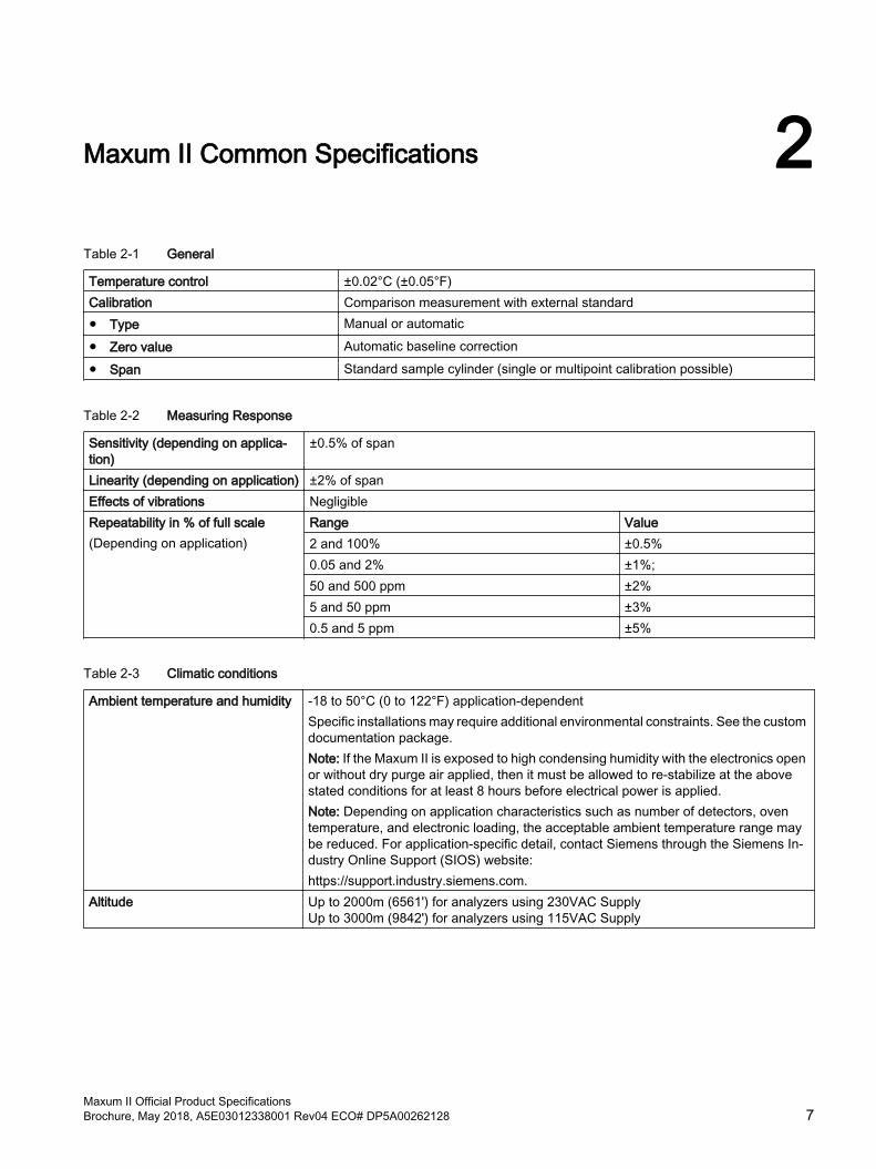
Maxum II Common Specifications 2Table 2-1 General
Temperature control ±0.02°C (±0.05°F)Calibration Comparison measurement with external standard● Type Manual or automatic● Zero value Automatic baseline correction● Span Standard sample cylinder (single or multipoint calibration possible)
Table 2-2 Measuring Response
Sensitivity (depending on applica‐tion)
±0.5% of span
Linearity (depending on application) ±2% of spanEffects of vibrations NegligibleRepeatability in % of full scale(Depending on application)
Range Value2 and 100% ±0.5%0.05 and 2% ±1%; 50 and 500 ppm ±2%5 and 50 ppm ±3%0.5 and 5 ppm ±5%
Table 2-3 Climatic conditions
Ambient temperature and humidity -18 to 50°C (0 to 122°F) application-dependentSpecific installations may require additional environmental constraints. See the custom documentation package. Note: If the Maxum II is exposed to high condensing humidity with the electronics open or without dry purge air applied, then it must be allowed to re-stabilize at the above stated conditions for at least 8 hours before electrical power is applied.Note: Depending on application characteristics such as number of detectors, oven temperature, and electronic loading, the acceptable ambient temperature range may be reduced. For application-specific detail, contact Siemens through the Siemens In‐dustry Online Support (SIOS) website:https://support.industry.siemens.com.
Altitude Up to 2000m (6561') for analyzers using 230VAC Supply Up to 3000m (9842') for analyzers using 115VAC Supply
Maxum II Official Product SpecificationsBrochure, May 2018, A5E03012338001 Rev04 ECO# DP5A00262128 7
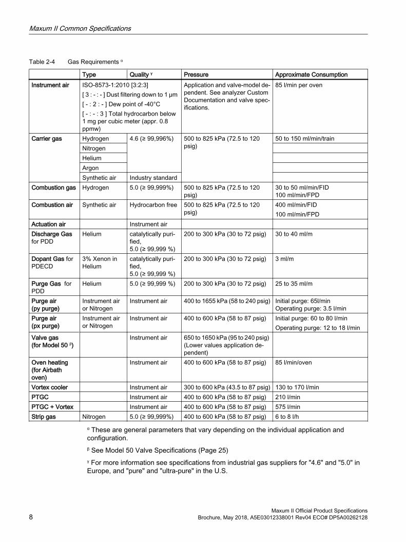
Table 2-4 Gas Requirements α
Type Quality γ Pressure Approximate ConsumptionInstrument air ISO-8573-1:2010 [3:2:3]
[ 3 : - : - ] Dust filtering down to 1 μm [ - : 2 : - ] Dew point of -40°C[ - : - : 3 ] Total hydrocarbon below 1 mg per cubic meter (appr. 0.8 ppmw)
Application and valve-model de‐pendent. See analyzer Custom Documentation and valve spec‐ifications.
85 l/min per oven
Carrier gas Hydrogen 4.6 (≥ 99,996%) 500 to 825 kPa (72.5 to 120 psig)
50 to 150 ml/min/trainNitrogen Helium Argon Synthetic air Industry standard
Combustion gas Hydrogen 5.0 (≥ 99,999%) 500 to 825 kPa (72.5 to 120 psig)
30 to 50 ml/min/FID100 ml/min/FPD
Combustion air Synthetic air Hydrocarbon free 500 to 825 kPa (72.5 to 120 psig)
400 ml/min/FID100 ml/min/FPD
Actuation air Instrument air Discharge Gas for PDD
Helium catalytically puri‐fied, 5.0 (≥ 99,999 %)
200 to 300 kPa (30 to 72 psig) 30 to 40 ml/m
Dopant Gas for PDECD
3% Xenon in Helium
catalytically puri‐fied, 5.0 (≥ 99,999 %)
200 to 300 kPa (30 to 72 psig) 3 ml/m
Purge Gas for PDD
Helium 5.0 (≥ 99,999 %) 200 to 300 kPa (30 to 72 psig) 25 to 35 ml/m
Purge air(py purge)
Instrument air or Nitrogen
Instrument air 400 to 1655 kPa (58 to 240 psig) Initial purge: 65l/minOperating purge: 3.5 l/min
Purge air(px purge)
Instrument air or Nitrogen
Instrument air 400 to 600 kPa (58 to 87 psig) Initial purge: 60 to 80 l/minOperating purge: 12 to 18 l/min
Valve gas(for Model 50 β)
Instrument air 650 to 1650 kPa (95 to 240 psig) (Lower values application de‐pendent)
Oven heating (for Airbath oven)
Instrument air 400 to 600 kPa (58 to 87 psig) 85 l/min/oven
Vortex cooler Instrument air 300 to 600 kPa (43.5 to 87 psig) 130 to 170 l/minPTGC Instrument air 400 to 600 kPa (58 to 87 psig) 210 l/minPTGC + Vortex Instrument air 400 to 600 kPa (58 to 87 psig) 575 l/minStrip gas Nitrogen 5.0 (≥ 99,999%) 400 to 600 kPa (58 to 87 psig) 6 to 8 l/h
α These are general parameters that vary depending on the individual application and configuration. β See Model 50 Valve Specifications (Page 25)γ For more information see specifications from industrial gas suppliers for "4.6" and "5.0" in Europe, and "pure" and "ultra-pure" in the U.S.
Maxum II Common Specifications
Maxum II Official Product Specifications8 Brochure, May 2018, A5E03012338001 Rev04 ECO# DP5A00262128
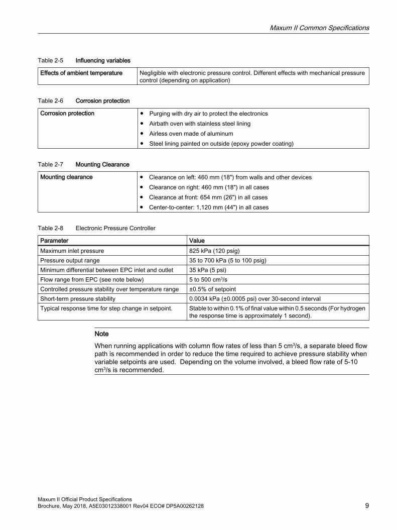
Table 2-5 Influencing variables
Effects of ambient temperature Negligible with electronic pressure control. Different effects with mechanical pressure control (depending on application)
Table 2-6 Corrosion protection
Corrosion protection ● Purging with dry air to protect the electronics● Airbath oven with stainless steel lining● Airless oven made of aluminum● Steel lining painted on outside (epoxy powder coating)
Table 2-7 Mounting Clearance
Mounting clearance ● Clearance on left: 460 mm (18") from walls and other devices ● Clearance on right: 460 mm (18") in all cases ● Clearance at front: 654 mm (26") in all cases ● Center-to-center: 1,120 mm (44") in all cases
Table 2-8 Electronic Pressure Controller
Parameter ValueMaximum inlet pressure 825 kPa (120 psig)Pressure output range 35 to 700 kPa (5 to 100 psig)Minimum differential between EPC inlet and outlet 35 kPa (5 psi)Flow range from EPC (see note below) 5 to 500 cm3/sControlled pressure stability over temperature range ±0.5% of setpointShort-term pressure stability 0.0034 kPa (±0.0005 psi) over 30-second intervalTypical response time for step change in setpoint. Stable to within 0.1% of final value within 0.5 seconds (For hydrogen
the response time is approximately 1 second).
Note
When running applications with column flow rates of less than 5 cm3/s, a separate bleed flow path is recommended in order to reduce the time required to achieve pressure stability when variable setpoints are used. Depending on the volume involved, a bleed flow rate of 5-10 cm3/s is recommended.
Maxum II Common Specifications
Maxum II Official Product SpecificationsBrochure, May 2018, A5E03012338001 Rev04 ECO# DP5A00262128 9
Maxum II Common Specifications
Maxum II Official Product Specifications10 Brochure, May 2018, A5E03012338001 Rev04 ECO# DP5A00262128
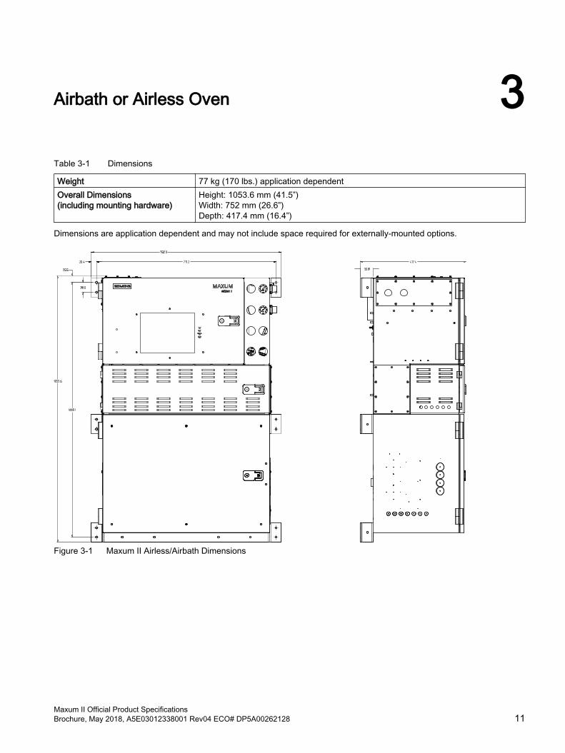
Airbath or Airless Oven 3Table 3-1 Dimensions
Weight 77 kg (170 lbs.) application dependentOverall Dimensions(including mounting hardware)
Height: 1053.6 mm (41.5”)Width: 752 mm (26.6”)Depth: 417.4 mm (16.4”)
Dimensions are application dependent and may not include space required for externally-mounted options.
Figure 3-1 Maxum II Airless/Airbath Dimensions
Maxum II Official Product SpecificationsBrochure, May 2018, A5E03012338001 Rev04 ECO# DP5A00262128 11
Table 3-2 Configuration
Oven options ● Single isothermal airbath oven or divided airbath oven with two independent isothermal zones
● Single oven or two independent, airless ovens in separate oven areas.● Programmable-temperature (PTGC) oven
Detector options ● Thermal conductivity● Flame ionization● Flame photometric● Pulse discharge detector in Helium ionization mode● Pulse discharge detector in Photo-ionization mode● Pulse discharge detector in Electron capture mode
Number of detectors ● 1, 2 or 3 in any combination of detector module types for airbath ovens (max. 2 FPDs)
● 1, or 2 in any combination of detector module types for airless ovens, up to 3 in special configurations
Sampling and column valves ● Diaphragm valves● Diaphragm plunger valves● Rotary valves● Liquid injection valve
Valveless option Live switchingColumn options Packed, micropacked or capillary columnsRegulation of gas supply Up to 8 electronic pressure regulator channels and up to 6 mechanical pressure reg‐
ulators
Table 3-3 Enclosure Protection
Ingress protection IP54Explosion protection ● Standard configurations:
● Certified according to ATEX with air or nitrogen purging for Zone 1 (II2G Ex ... IIB + H2 ... Gb)
● Suitable for use in non-hazardous areas and with non-dangerous conditions● Certified according to CSA C/US for use in Class 1, Div. 1, Groups B, C, D with air
or nitrogen purging ● Certified according to CSA C/US for use in Class 1, Div. 2, Groups B, C, D. Important note! Purging of the electronics area with instrument air or nitrogen is rec‐ommended to maintain optimum measurement performance. The PDD is not certified for hazardous areas.
EMI/RFI design ● CE-compatible; in conformity with 2014/30/EU (EMC directive) ● CE-compatible; in conformity with 2014/35/EU (low-voltage directive)● Tested according to EN 61010-1 / IEC 61010-1
Table 3-4 Electrical characteristics
Power supply ● Single-phase AC, 100 to 130 V or 195 to 260 V (dependent on configuration), 47 to 63 Hz
Airbath or Airless Oven
Maxum II Official Product Specifications12 Brochure, May 2018, A5E03012338001 Rev04 ECO# DP5A00262128
Table 3-5 Electrical inputs and outputs
Standard input and output ● 2 analog outputs● 4 digital outputs (1 for output of system faults, 3 are user-configurable)● 4 digital inputs;
Card slots for optional inputs and outputs via internal I2C bus
2
Input and output cards ● I2C_AIO: 8 analog outputs, 8 analog inputs, 2 digital inputs● I2C_DIO: 6 digital inputs and 8 digital outputs ● I2C_ADIO: 4 digital inputs and 4 digital outputs, 4 analog inputs and 4 analog
outputsDigital inputs ● Optically coupled with a common for all inputs.
● Self-powered floating-contact input, or configurable for sinking or sourcing current. ● Sourcing current mode: 24 V internal isolated supply, with positive terminal of
supply at common. ● Sinking current mode: 5 V internal isolated supply, with negative terminal of supply
at common.Digital outputs Floating double-throw contacts, maximum contact load rating 1 A at 30 V (AC or DC).
External diode shunt suppression should be used for inductive DC loads, preferably at the load
Analog inputs -20 to 20 mA into 50 Ω or-10 to 10 V Rin = 0.1 MΩWith alternate insulation up to 10 V
Analog outputs 0/4 to 20 mA into max. 750 Ω, common negative pole, electrically isolated from ground; freely connectable to ground
Termination SYSCON-based I/O: Terminal strip for braided or solid cable with maximum section of 1.5 mm2 (16AWG) Expansion board-based I/O: Screw terminal for shielded or solid cable with a maximum area of 0.82 mm2 (18AWG)
Table 3-6 Communication
Serial ports 4 RS232/RS485 ports, e.g. ModbusEthernet ● Standard 10/100 BaseT Ethernet with 4 RJ45 connectors e.g. Modbus TCP IP or
OPC● Optional ESBF board Fiber-optic 100Base FX multimode with ST connection 3 x
RJ45 and 1 x optical (Optical port uses LED instead of laser for safer diffused-energy fiber link; less than 40μW at approximately 1300nm)
Gas sample inlet conditions depend on application and valve choice.
See alsoValve Specifications (Page 25)
Airbath or Airless Oven
Maxum II Official Product SpecificationsBrochure, May 2018, A5E03012338001 Rev04 ECO# DP5A00262128 13
Table 3-7 Combustion gas supply
Combustion gas ● Hydrogen with a purity of 99.999%● Typical consumption quantity: 2 000 l/month per detector module
Combustion air ● Reference air (< 1 ppm THC, O2 concentration 20 to 21%). Synthetic air, or supply through instrument air with catalytic purification (optional).
● Typical consumption quantity: 26 000 l/month
Airbath or Airless Oven
Maxum II Official Product Specifications14 Brochure, May 2018, A5E03012338001 Rev04 ECO# DP5A00262128
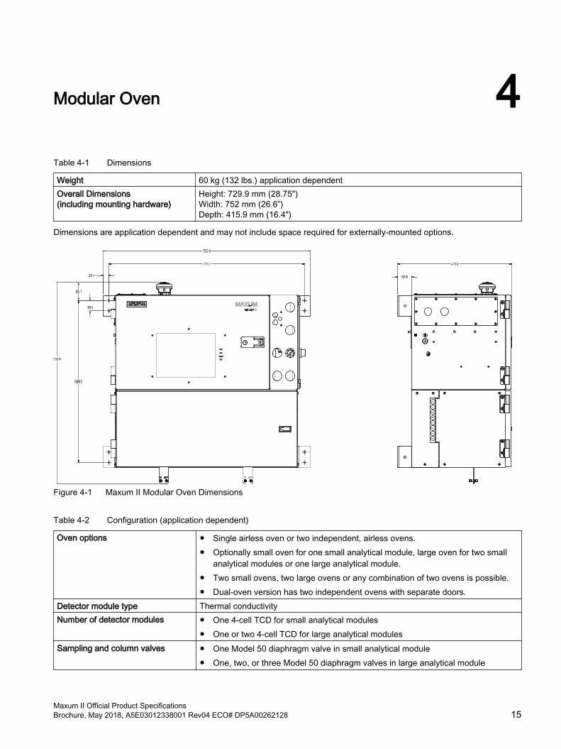
Modular Oven 4Table 4-1 Dimensions
Weight 60 kg (132 lbs.) application dependentOverall Dimensions(including mounting hardware)
Height: 729.9 mm (28.75")Width: 752 mm (26.6”)Depth: 415.9 mm (16.4")
Dimensions are application dependent and may not include space required for externally-mounted options.
Figure 4-1 Maxum II Modular Oven Dimensions
Table 4-2 Configuration (application dependent)
Oven options ● Single airless oven or two independent, airless ovens. ● Optionally small oven for one small analytical module, large oven for two small
analytical modules or one large analytical module. ● Two small ovens, two large ovens or any combination of two ovens is possible. ● Dual-oven version has two independent ovens with separate doors.
Detector module type Thermal conductivityNumber of detector modules ● One 4-cell TCD for small analytical modules
● One or two 4-cell TCD for large analytical modulesSampling and column valves ● One Model 50 diaphragm valve in small analytical module
● One, two, or three Model 50 diaphragm valves in large analytical module
Maxum II Official Product SpecificationsBrochure, May 2018, A5E03012338001 Rev04 ECO# DP5A00262128 15
Columns Packed, micropacked or metal capillary columnsRegulation of gas supply Up to 6 electronic pressure regulator channels and up to 4 mechanical pressure reg‐
ulators
Table 4-3 Enclosure Protection
Ingress protection IP54, Category 1Explosion protection Standard configurations:
● Certified according to IECEx with air or nitrogen purging for Zone 1 (IIC T4 Gb)● Certified according to ATEX with air or nitrogen purging for Zone 1 (II2G Ex ... IIC ...
Gb)● Suitable for use in non-hazardous areas and with non-dangerous conditions● Certified according to CSA C/US for use in Class 1, Div. 1, Groups A, B, C, D with
air or nitrogen purging ● Certified according to CSA C/US for use in Class 1, Div. 2, Groups A, B, C, D. Important note! Purging of the electronics area with instrument air or nitrogen is rec‐ommended to maintain optimum measurement performance.
EMI/RFI design ● CE-compatible; in conformity with 2014/30/EU (EMC directive) ● CE-compatible; in conformity with 2014/35/EU (low-voltage directive)● Tested according to EN 61010-1 / IEC 61010-1
Table 4-4 Electrical characteristics
Power supply ● Single-phase AC, 85 to 264 V, 47 to 63 Hz ● Max. 655 VA, nominal 280 VA ● Optional: External 24 V DC ±10% 10 A with 32 V voltage limiting Max. 100 mV
residual ripple and interferences minimum to maximum at 20 MHz ● Fusing at max. 20 A ● External 24 V supply must accept minus to ground
Table 4-5 Electrical inputs and outputs
CIM-based IO ● 2 digital outputsCard slots for optional inputs and outputs via internal I2C bus
● 4 slots, maximum 2 IO cards (in IO tray)
Input and output cards ● I2C_AIO: 8 analog outputs, 8 analog inputs, 2 digital inputs● I2C_DIO: 6 digital inputs and 8 digital outputs ● I2C_ADIO: 4 digital inputs and 4 digital outputs, 4 analog inputs and 4 analog
outputsDigital inputs ● Optically coupled with a common for all inputs.
● Self-powered floating-contact input, or configurable for sinking or sourcing current. ● Sourcing current mode: 24 V internal isolated supply, with positive terminal of
supply at common. ● Sinking current mode: 5 V internal isolated supply, with negative terminal of supply
at common.
Modular Oven
Maxum II Official Product Specifications16 Brochure, May 2018, A5E03012338001 Rev04 ECO# DP5A00262128
Digital outputs Floating double-throw contacts, maximum contact load rating 1 A at 30 V (AC or DC). External diode shunt suppression should be used for inductive DC loads, preferably at the load
Analog inputs -20 to 20 mA into 50 Ω or-10 to 10 V Rin = 0.1 MΩWith alternate insulation up to 10 V
Analog outputs 0/4 to 20 mA into max. 750 Ω, common negative pole, electrically isolated from ground; freely connectable to ground
Termination SYSCON-based I/O: Terminal strip for braided or solid cable with maximum section of 1.5 mm2 (16AWG) Expansion board-based I/O: Spring contacts for shielded or solid cable with a maxi‐mum area of 0.82 mm2 (18AWG)
Table 4-6 Communication
Serial ports 2● Serial Port 1: RS232/RS485 selectable● Serial Port 2: RS485 mode only
Ethernet ● Standard 10/100 BaseT Ethernet with 2 RJ45 connectors e.g. Modbus TCP IP or OPC
● Optional ESBF board Fiber-optic 100Base FX multimode with ST connection 3 x RJ45 and 1 x optical (Optical port uses LED instead of laser for safer diffused-energy fiber link; less than 40μW at approximately 1300nm)
Table 4-7 Gas sample inlet conditions
Sample flow 5 to 100 ml/min (depending on application)Sample filter size 0.1 μm with gaseous samplesMinimum sample pressure 35 kPa (5 psig) standardMaximum sample pressure 200 kPa (29 psig) standardMaximum sample temperature 80°C (176°F) standard; higher temperature as optionMaterials in contact with sample Stainless steel, aluminum, Viton, polyimide and Teflon
Modular Oven
Maxum II Official Product SpecificationsBrochure, May 2018, A5E03012338001 Rev04 ECO# DP5A00262128 17
Modular Oven
Maxum II Official Product Specifications18 Brochure, May 2018, A5E03012338001 Rev04 ECO# DP5A00262128
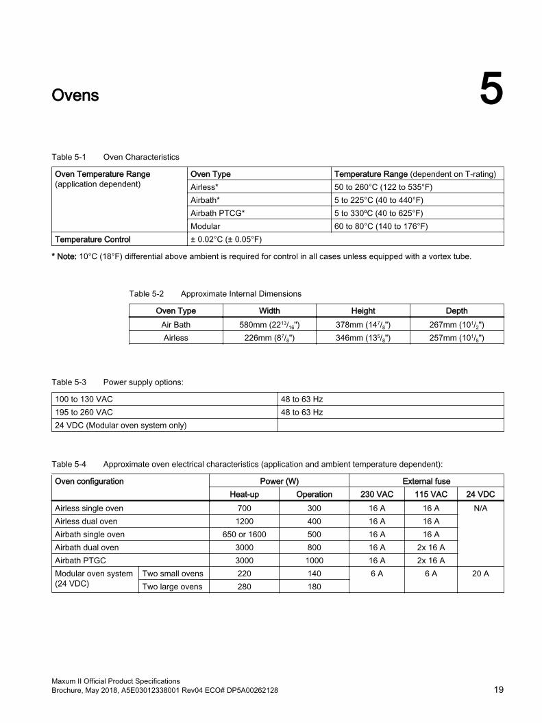
Ovens 5Table 5-1 Oven Characteristics
Oven Temperature Range(application dependent)
Oven Type Temperature Range (dependent on T-rating)Airless* 50 to 260°C (122 to 535°F)Airbath* 5 to 225°C (40 to 440°F) Airbath PTCG* 5 to 330ºC (40 to 625°F)Modular 60 to 80°C (140 to 176°F)
Temperature Control ± 0.02°C (± 0.05°F)
* Note: 10°C (18°F) differential above ambient is required for control in all cases unless equipped with a vortex tube.
Table 5-2 Approximate Internal Dimensions
Oven Type Width Height DepthAir Bath 580mm (2213/16") 378mm (147/8") 267mm (101/2")Airless 226mm (87/8") 346mm (135/8") 257mm (101/8")
Table 5-3 Power supply options:
100 to 130 VAC 48 to 63 Hz195 to 260 VAC 48 to 63 Hz24 VDC (Modular oven system only)
Table 5-4 Approximate oven electrical characteristics (application and ambient temperature dependent):
Oven configuration Power (W) External fuseHeat-up Operation 230 VAC 115 VAC 24 VDC
Airless single oven 700 300 16 A 16 A N/AAirless dual oven 1200 400 16 A 16 AAirbath single oven 650 or 1600 500 16 A 16 AAirbath dual oven 3000 800 16 A 2x 16 AAirbath PTGC 3000 1000 16 A 2x 16 AModular oven system (24 VDC)
Two small ovens 220 140 6 A 6 A 20 ATwo large ovens 280 180
Maxum II Official Product SpecificationsBrochure, May 2018, A5E03012338001 Rev04 ECO# DP5A00262128 19
Ovens
Maxum II Official Product Specifications20 Brochure, May 2018, A5E03012338001 Rev04 ECO# DP5A00262128
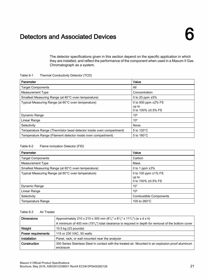
Detectors and Associated Devices 6The detector specifications given in this section depend on the specific application in which they are installed, and reflect the performance of the component when used in a Maxum II Gas Chromatograph as a system.
Table 6-1 Thermal Conductivity Detector (TCD)
Parameter ValueTarget Components AllMeasurement Type ConcentrationSmallest Measuring Range (at 60°C oven temperature) 0 to 20 ppm ±5%Typical Measuring Range (at 60°C oven temperature) 0 to 500 ppm ±2% FS
up to 0 to 100% ±0.5% FS
Dynamic Range 105
Linear Range 104
Selectivity NoneTemperature Range (Thermistor bead detector inside oven compartment) 5 to 120°C Temperature Range (Filament detector inside oven compartment) 5 to 180°C
Table 6-2 Flame Ionization Detector (FID)
Parameter ValueTarget Components CarbonMeasurement Type MassSmallest Measuring Range (at 60°C oven temperature) 0 to 1 ppm ±3%Typical Measuring Range (at 60°C oven temperature) 0 to 100 ppm ±1% FS
up to 0 to 100% ±0.5% FS
Dynamic Range 107
Linear Range 106
Selectivity Combustible ComponentsTemperature Range 105 to 260°C
Table 6-3 Air Treater
Dimensions Approximately 210 x 210 x 300 mm (81/4" x 81/4" x 113/4") (w x d x h)A minimum of 400 mm (153/4") total clearance is required in depth for removal of the bottom cover
Weight 10.5 kg (23 pounds)Power requirements 115 or 230 VAC, 50 wattsInstallation Panel, rack, or wall mounted near the analyzerConstruction 300 Series Stainless Steel in contact with the treated air. Mounted in an explosion proof aluminum
enclosure
Maxum II Official Product SpecificationsBrochure, May 2018, A5E03012338001 Rev04 ECO# DP5A00262128 21
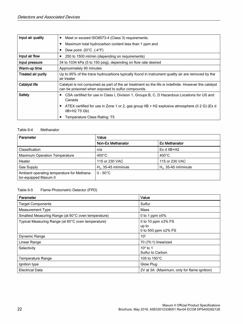
Input air quality ● Meet or exceed ISO8573-4 (Class 3) requirements. ● Maximum total hydrocarbon content less than 1 ppm and ● Dew point -20°C (-4°F)
Input air flow ● 250 to 1500 ml/min (depending on requirements)Input pressure 34 to 1034 kPa (5 to 150 psig), depending on flow rate desiredWarm-up time Approximately 90 minutesTreated air purity Up to 95% of the trace hydrocarbons typically found in instrument quality air are removed by the
air treaterCatalyst life Catalyst is not consumed as part of the air treatment so the life is indefinite. However the catalyst
can be poisoned when exposed to sulfur compounds.Safety ● CSA certified for use in Class I, Division 1, Groups B, C, D Hazardous Locations for US and
Canada● ATEX certified for use in Zone 1 or 2, gas group IIB + H2 explosive atmosphere (II 2 G) (Ex d
IIB+H2 T5 Gb)● Temperature Class Rating: T5
Table 6-4 Methanator
Parameter ValueNon-Ex Methanator Ex Methanator
Classification n/a Ex d IIB+H2Maximum Operation Temperature 400°C 400°CHeater 115 or 230 VAC 115 or 230 VACGas Supply H2, 35-45 ml/minute H2, 35-45 ml/minuteAmbient operating temperature for Methana‐tor-equipped Maxum II
0 - 50°C
Table 6-5 Flame Photometric Detector (FPD)
Parameter ValueTarget Components SulfurMeasurement Type MassSmallest Measuring Range (at 60°C oven temperature) 0 to 1 ppm ±5%Typical Measuring Range (at 60°C oven temperature) 0 to 10 ppm ±3% FS
up to 0 to 500 ppm ±2% FS
Dynamic Range 102
Linear Range 70 (70:1) linearizedSelectivity 104 to 1
Sulfur to CarbonTemperature Range 105 to 150°CIgnition type Glow PlugElectrical Data 2V at 3A (Maximum, only for flame ignition)
Detectors and Associated Devices
Maxum II Official Product Specifications22 Brochure, May 2018, A5E03012338001 Rev04 ECO# DP5A00262128
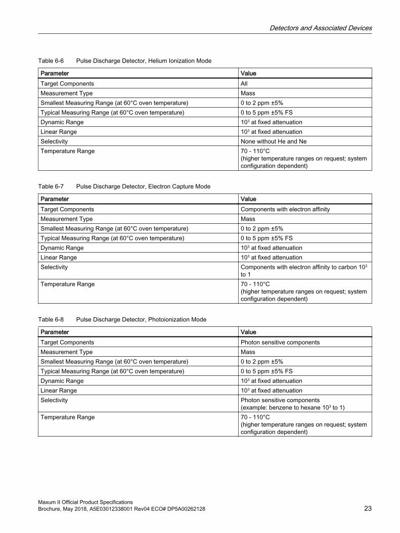
Table 6-6 Pulse Discharge Detector, Helium Ionization Mode
Parameter ValueTarget Components AllMeasurement Type MassSmallest Measuring Range (at 60°C oven temperature) 0 to 2 ppm ±5%Typical Measuring Range (at 60°C oven temperature) 0 to 5 ppm ±5% FSDynamic Range 103 at fixed attenuationLinear Range 103 at fixed attenuationSelectivity None without He and NeTemperature Range 70 - 110°C
(higher temperature ranges on request; system configuration dependent)
Table 6-7 Pulse Discharge Detector, Electron Capture Mode
Parameter ValueTarget Components Components with electron affinityMeasurement Type MassSmallest Measuring Range (at 60°C oven temperature) 0 to 2 ppm ±5%Typical Measuring Range (at 60°C oven temperature) 0 to 5 ppm ±5% FSDynamic Range 103 at fixed attenuationLinear Range 103 at fixed attenuationSelectivity Components with electron affinity to carbon 103
to 1Temperature Range 70 - 110°C
(higher temperature ranges on request; system configuration dependent)
Table 6-8 Pulse Discharge Detector, Photoionization Mode
Parameter ValueTarget Components Photon sensitive componentsMeasurement Type MassSmallest Measuring Range (at 60°C oven temperature) 0 to 2 ppm ±5%Typical Measuring Range (at 60°C oven temperature) 0 to 5 ppm ±5% FSDynamic Range 103 at fixed attenuationLinear Range 103 at fixed attenuationSelectivity Photon sensitive components
(example: benzene to hexane 103 to 1)Temperature Range 70 - 110°C
(higher temperature ranges on request; system configuration dependent)
Detectors and Associated Devices
Maxum II Official Product SpecificationsBrochure, May 2018, A5E03012338001 Rev04 ECO# DP5A00262128 23
Detectors and Associated Devices
Maxum II Official Product Specifications24 Brochure, May 2018, A5E03012338001 Rev04 ECO# DP5A00262128
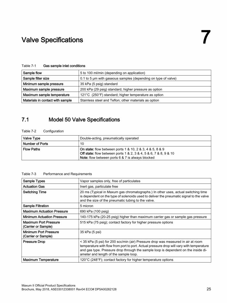
Valve Specifications 7Table 7-1 Gas sample inlet conditions
Sample flow 5 to 100 ml/min (depending on application)Sample filter size 0.1 to 5 μm with gaseous samples (depending on type of valve)Minimum sample pressure 35 kPa (5 psig) standardMaximum sample pressure 200 kPa (29 psig) standard, higher pressure as optionMaximum sample temperature 121°C (250°F) standard; higher temperature as optionMaterials in contact with sample Stainless steel and Teflon; other materials as option
7.1 Model 50 Valve Specifications
Table 7-2 Configuration
Valve Type Double-acting, pneumatically operatedNumber of Ports 10Flow Paths On state: flow between ports 1 & 10, 2 & 3, 4 & 5, 8 & 9
Off state: flow between ports 1 & 2, 3 & 4, 5 & 6, 7 & 8, 9 & 10 Note: flow between ports 6 & 7 is always blocked
Table 7-3 Performance and Requirements
Sample Types Vapor samples only, free of particulatesActuation Gas Inert gas, particulate freeSwitching Time 20 ms (Typical in Maxum gas chromatographs.) In other uses, actual switching time
is dependent on the type of solenoids used to deliver the pneumatic signal to the valve and the size of the pneumatic tubing to the valve.
Sample Filtration 5 micronMaximum Actuation Pressure 690 kPa (100 psig)Minimum Actuation Pressure 140-175 kPa (20-25 psig) higher than maximum carrier gas or sample gas pressureMaximum Port Pressure (Carrier or Sample)
515 kPa (75 psig); contact factory for higher pressure options
Minimum Port Pressure (Carrier or Sample)
35 kPa (5 psi)
Pressure Drop < 35 kPa (5 psi) for 200 scc/min (air) Pressure drop was measured in air at room temperature with flow from port to port. Actual pressure drop will vary with temperature and gas type. Pressure drop through the sample loop is dependent on the inside di‐ameter and length of the sample loop.
Maximum Temperature 120°C (248°F); contact factory for higher temperature options
Maxum II Official Product SpecificationsBrochure, May 2018, A5E03012338001 Rev04 ECO# DP5A00262128 25
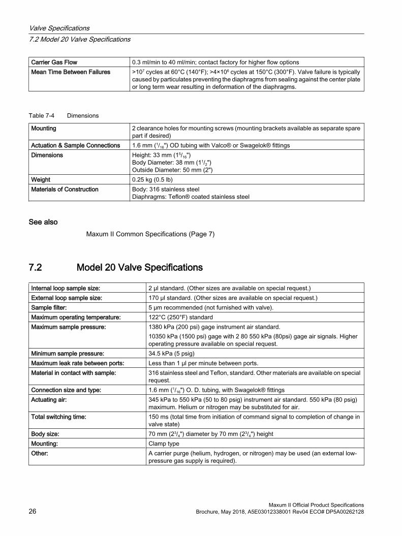
Carrier Gas Flow 0.3 ml/min to 40 ml/min; contact factory for higher flow optionsMean Time Between Failures >107 cycles at 60°C (140°F); >4×10⁶ cycles at 150°C (300°F). Valve failure is typically
caused by particulates preventing the diaphragms from sealing against the center plate or long term wear resulting in deformation of the diaphragms.
Table 7-4 Dimensions
Mounting 2 clearance holes for mounting screws (mounting brackets available as separate spare part if desired)
Actuation & Sample Connections 1.6 mm (1/16") OD tubing with Valco® or Swagelok® fittingsDimensions Height: 33 mm (15/16")
Body Diameter: 38 mm (11/2")Outside Diameter: 50 mm (2")
Weight 0.25 kg (0.5 lb)Materials of Construction Body: 316 stainless steel
Diaphragms: Teflon® coated stainless steel
See alsoMaxum II Common Specifications (Page 7)
7.2 Model 20 Valve Specifications
Internal loop sample size: 2 μl standard. (Other sizes are available on special request.)External loop sample size: 170 μl standard. (Other sizes are available on special request.)Sample filter: 5 μm recommended (not furnished with valve).Maximum operating temperature: 122°C (250°F) standard Maximum sample pressure: 1380 kPa (200 psi) gage instrument air standard.
10350 kPa (1500 psi) gage with 2 80 550 kPa (80psi) gage air signals. Higher operating pressure available on special request.
Minimum sample pressure: 34.5 kPa (5 psig)Maximum leak rate between ports: Less than 1 μl per minute between ports.Material in contact with sample: 316 stainless steel and Teflon, standard. Other materials are available on special
request.Connection size and type: 1.6 mm (1/16") O. D. tubing, with Swagelok® fittingsActuating air: 345 kPa to 550 kPa (50 to 80 psig) instrument air standard. 550 kPa (80 psig)
maximum. Helium or nitrogen may be substituted for air. Total switching time: 150 ms (total time from initiation of command signal to completion of change in
valve state)Body size: 70 mm (23/4") diameter by 70 mm (23/4") heightMounting: Clamp typeOther: A carrier purge (helium, hydrogen, or nitrogen) may be used (an external low-
pressure gas supply is required).
Valve Specifications7.2 Model 20 Valve Specifications
Maxum II Official Product Specifications26 Brochure, May 2018, A5E03012338001 Rev04 ECO# DP5A00262128
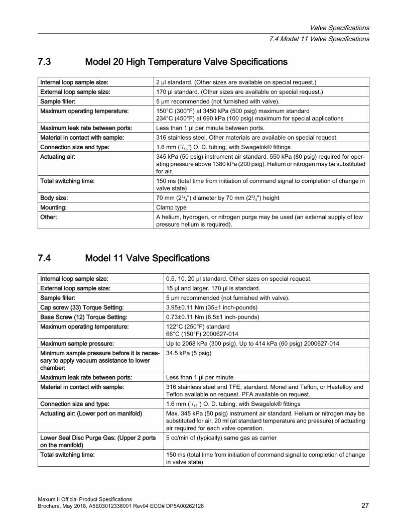
7.3 Model 20 High Temperature Valve Specifications
Internal loop sample size: 2 μl standard. (Other sizes are available on special request.)External loop sample size: 170 μl standard. (Other sizes are available on special request.)Sample filter: 5 μm recommended (not furnished with valve).Maximum operating temperature: 150°C (300°F) at 3450 kPa (500 psig) maximum standard
234°C (450°F) at 690 kPa (100 psig) maximum for special applications Maximum leak rate between ports: Less than 1 μl per minute between ports.Material in contact with sample: 316 stainless steel. Other materials are available on special request.Connection size and type: 1.6 mm (1/16") O. D. tubing, with Swagelok® fittingsActuating air: 345 kPa (50 psig) instrument air standard. 550 kPa (80 psig) required for oper‐
ating pressure above 1380 kPa (200 psig). Helium or nitrogen may be substituted for air.
Total switching time: 150 ms (total time from initiation of command signal to completion of change in valve state)
Body size: 70 mm (23/4") diameter by 70 mm (23/4") heightMounting: Clamp typeOther: A helium, hydrogen, or nitrogen purge may be used (an external supply of low
pressure helium is required).
7.4 Model 11 Valve Specifications
Internal loop sample size: 0.5, 10, 20 μl standard. Other sizes on special request.External loop sample size: 15 μl and larger. 170 μl is standard.Sample filter: 5 μm recommended (not furnished with valve).Cap screw (33) Torque Setting: 3.95±0.11 Nm (35±1 inch-pounds)Base Screw (12) Torque Setting: 0.73±0.11 Nm (6.5±1 inch-pounds)Maximum operating temperature: 122°C (250°F) standard
66°C (150°F) 2000627-014Maximum sample pressure: Up to 2068 kPa (300 psig). Up to 414 kPa (60 psig) 2000627-014Minimum sample pressure before it is neces‐sary to apply vacuum assistance to lower chamber:
34.5 kPa (5 psig)
Maximum leak rate between ports: Less than 1 μl per minuteMaterial in contact with sample: 316 stainless steel and TFE, standard. Monel and Teflon, or Hastelloy and
Teflon available on request. PFA available on request.Connection size and type: 1.6 mm (1/16") O. D. tubing, with Swagelok® fittingsActuating air: (Lower port on manifold) Max. 345 kPa (50 psig) instrument air standard. Helium or nitrogen may be
substituted for air. 20 ml (at standard temperature and pressure) of actuating air required for each valve operation.
Lower Seal Disc Purge Gas: (Upper 2 ports on the manifold)
5 cc/min of (typically) same gas as carrier
Total switching time: 150 ms (total time from initiation of command signal to completion of change in valve state)
Valve Specifications7.4 Model 11 Valve Specifications
Maxum II Official Product SpecificationsBrochure, May 2018, A5E03012338001 Rev04 ECO# DP5A00262128 27
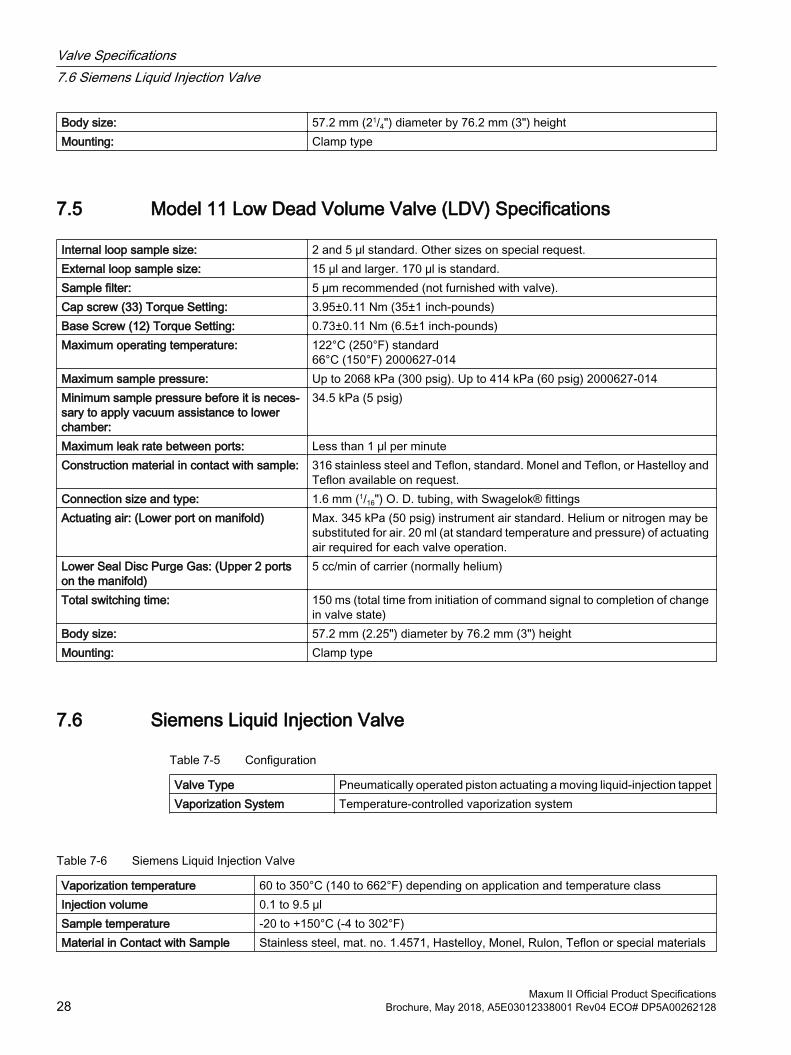
Body size: 57.2 mm (21/4") diameter by 76.2 mm (3") heightMounting: Clamp type
7.5 Model 11 Low Dead Volume Valve (LDV) Specifications
Internal loop sample size: 2 and 5 μl standard. Other sizes on special request.External loop sample size: 15 μl and larger. 170 μl is standard.Sample filter: 5 μm recommended (not furnished with valve).Cap screw (33) Torque Setting: 3.95±0.11 Nm (35±1 inch-pounds)Base Screw (12) Torque Setting: 0.73±0.11 Nm (6.5±1 inch-pounds)Maximum operating temperature: 122°C (250°F) standard
66°C (150°F) 2000627-014Maximum sample pressure: Up to 2068 kPa (300 psig). Up to 414 kPa (60 psig) 2000627-014Minimum sample pressure before it is neces‐sary to apply vacuum assistance to lower chamber:
34.5 kPa (5 psig)
Maximum leak rate between ports: Less than 1 μl per minuteConstruction material in contact with sample: 316 stainless steel and Teflon, standard. Monel and Teflon, or Hastelloy and
Teflon available on request.Connection size and type: 1.6 mm (1/16") O. D. tubing, with Swagelok® fittingsActuating air: (Lower port on manifold) Max. 345 kPa (50 psig) instrument air standard. Helium or nitrogen may be
substituted for air. 20 ml (at standard temperature and pressure) of actuating air required for each valve operation.
Lower Seal Disc Purge Gas: (Upper 2 ports on the manifold)
5 cc/min of carrier (normally helium)
Total switching time: 150 ms (total time from initiation of command signal to completion of change in valve state)
Body size: 57.2 mm (2.25") diameter by 76.2 mm (3") heightMounting: Clamp type
7.6 Siemens Liquid Injection Valve
Table 7-5 Configuration
Valve Type Pneumatically operated piston actuating a moving liquid-injection tappetVaporization System Temperature-controlled vaporization system
Table 7-6 Siemens Liquid Injection Valve
Vaporization temperature 60 to 350°C (140 to 662°F) depending on application and temperature classInjection volume 0.1 to 9.5 μlSample temperature -20 to +150°C (-4 to 302°F)Material in Contact with Sample Stainless steel, mat. no. 1.4571, Hastelloy, Monel, Rulon, Teflon or special materials
Valve Specifications7.6 Siemens Liquid Injection Valve
Maxum II Official Product Specifications28 Brochure, May 2018, A5E03012338001 Rev04 ECO# DP5A00262128
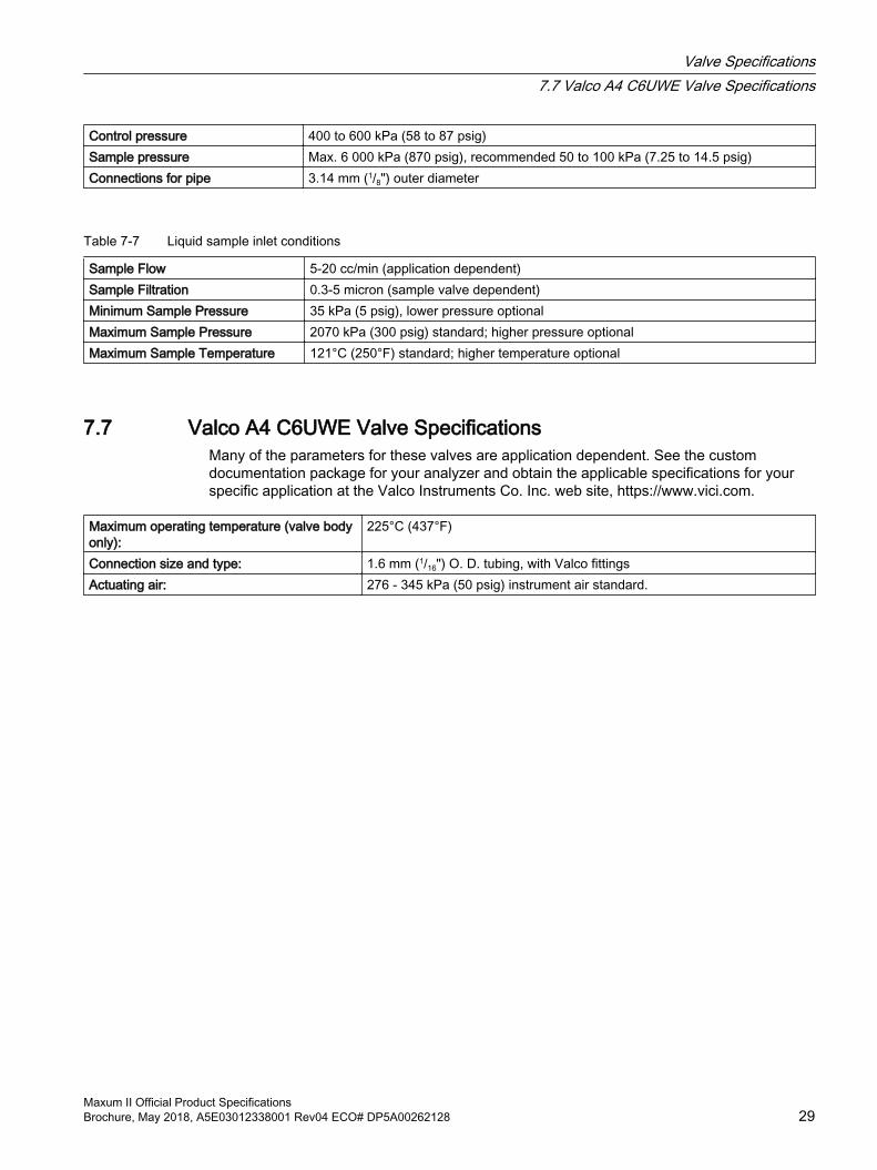
Control pressure 400 to 600 kPa (58 to 87 psig)Sample pressure Max. 6 000 kPa (870 psig), recommended 50 to 100 kPa (7.25 to 14.5 psig)Connections for pipe 3.14 mm (1/8") outer diameter
Table 7-7 Liquid sample inlet conditions
Sample Flow 5-20 cc/min (application dependent)Sample Filtration 0.3-5 micron (sample valve dependent)Minimum Sample Pressure 35 kPa (5 psig), lower pressure optionalMaximum Sample Pressure 2070 kPa (300 psig) standard; higher pressure optionalMaximum Sample Temperature 121°C (250°F) standard; higher temperature optional
7.7 Valco A4 C6UWE Valve SpecificationsMany of the parameters for these valves are application dependent. See the custom documentation package for your analyzer and obtain the applicable specifications for your specific application at the Valco Instruments Co. Inc. web site, https://www.vici.com.
Maximum operating temperature (valve body only):
225°C (437°F)
Connection size and type: 1.6 mm (1/16") O. D. tubing, with Valco fittingsActuating air: 276 - 345 kPa (50 psig) instrument air standard.
Valve Specifications7.7 Valco A4 C6UWE Valve Specifications
Maxum II Official Product SpecificationsBrochure, May 2018, A5E03012338001 Rev04 ECO# DP5A00262128 29
Valve Specifications7.7 Valco A4 C6UWE Valve Specifications
Maxum II Official Product Specifications30 Brochure, May 2018, A5E03012338001 Rev04 ECO# DP5A00262128
Network Access Unit 8Table 8-1 Dimensions
Mounting Options ● Rack-mount case● Wall-mount case
Weight 15 kg (33 lbs.)
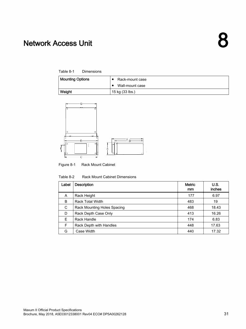
Figure 8-1 Rack Mount Cabinet
Table 8-2 Rack Mount Cabinet Dimensions
Label Description Metric mm
U.S. inches
A Rack Height 177 6.97B Rack Total Width 483 19 C Rack Mounting Holes Spacing 468 18.43D Rack Depth Case Only 413 16.26E Rack Handle 174 6.83F Rack Depth with Handles 448 17.63 G Case Width 440 17.32
Maxum II Official Product SpecificationsBrochure, May 2018, A5E03012338001 Rev04 ECO# DP5A00262128 31
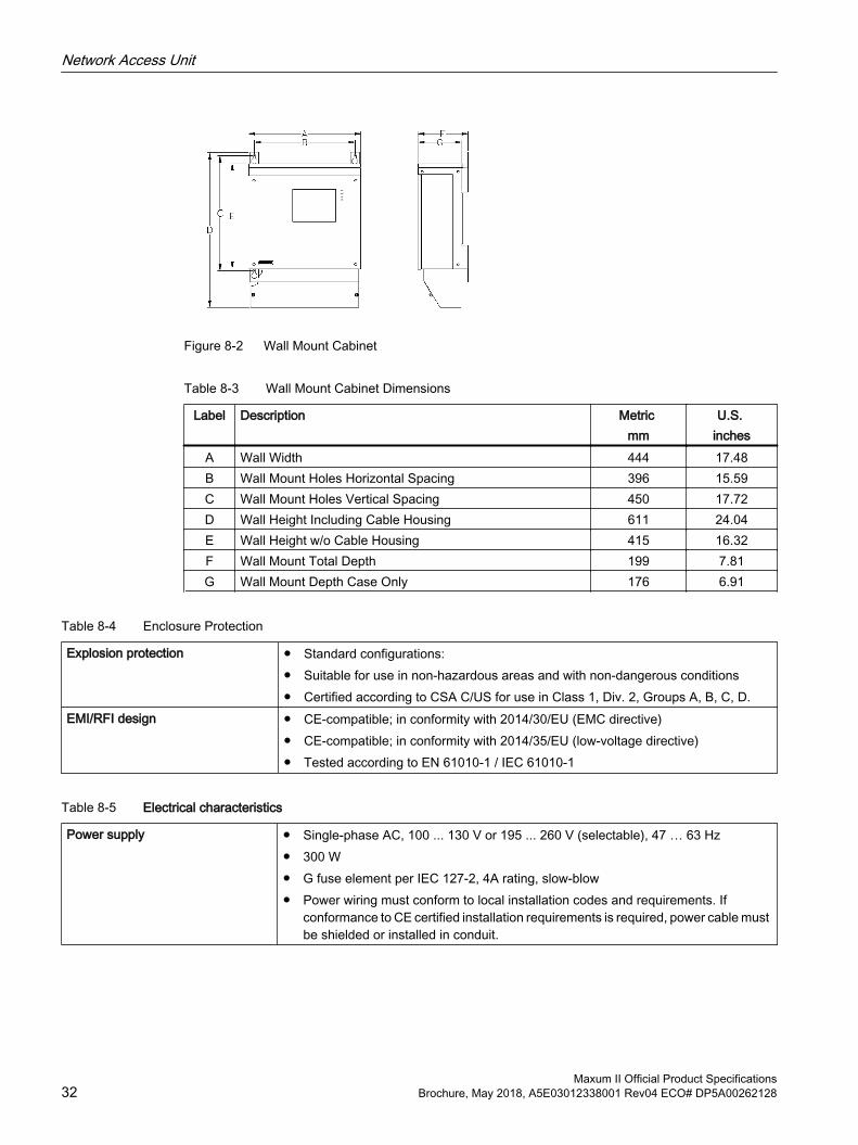
Figure 8-2 Wall Mount Cabinet
Table 8-3 Wall Mount Cabinet Dimensions
Label Description Metric mm
U.S. inches
A Wall Width 444 17.48B Wall Mount Holes Horizontal Spacing 396 15.59C Wall Mount Holes Vertical Spacing 450 17.72D Wall Height Including Cable Housing 611 24.04E Wall Height w/o Cable Housing 415 16.32F Wall Mount Total Depth 199 7.81G Wall Mount Depth Case Only 176 6.91
Table 8-4 Enclosure Protection
Explosion protection ● Standard configurations:● Suitable for use in non-hazardous areas and with non-dangerous conditions● Certified according to CSA C/US for use in Class 1, Div. 2, Groups A, B, C, D.
EMI/RFI design ● CE-compatible; in conformity with 2014/30/EU (EMC directive) ● CE-compatible; in conformity with 2014/35/EU (low-voltage directive)● Tested according to EN 61010-1 / IEC 61010-1
Table 8-5 Electrical characteristics
Power supply ● Single-phase AC, 100 ... 130 V or 195 ... 260 V (selectable), 47 … 63 Hz● 300 W● G fuse element per IEC 127-2, 4A rating, slow-blow● Power wiring must conform to local installation codes and requirements. If
conformance to CE certified installation requirements is required, power cable must be shielded or installed in conduit.
Network Access Unit
Maxum II Official Product Specifications32 Brochure, May 2018, A5E03012338001 Rev04 ECO# DP5A00262128
Table 8-6 Electrical inputs and outputs
Standard input and output ● 2 analog outputs● 4 digital outputs (1 for output of system faults, 3 are user-configurable)● 4 digital inputs;
Card slots for optional inputs and outputs via internal I2C bus
7
Input and output cards ● I2C_AIO 8: 8 analog outputs, 8 analog inputs, 2 digital inputs● I2C_DIO: 6 digital inputs and 8 digital outputs ● I2C_ADIO: 4 digital inputs and 4 digital outputs, 4 analog inputs and 4 analog
outputsDigital inputs ● Optically coupled with a common for all inputs.
● Self-powered floating-contact input, or configurable for sinking or sourcing current. ● Sourcing current mode: 24V internal isolated supply, with positive terminal of supply
at common. ● Sinking current mode: 5V internal isolated supply, with negative terminal of supply
at common.Digital outputs Floating double-throw contacts, maximum contact load rating 1A at 30V (AC or DC).
External diode shunt suppression should be used for inductive DC loads, preferably at the load
Analog inputs -20 to +20mA into 50Ω or-10 to +10V Rin = 0.1MΩ, alternate insulation up to 10V
Analog outputs 0/4 to 20 mA into max. 750 Ω, common negative pole, electrically isolated from ground; freely connectable to ground
Termination ● SYSCON-based I/O: Terminal strip for braided or solid cable with maximum section of 16AWG (1.5mm2)
● Expansion board-based I/O: Spring contacts for shielded or solid cable with a maximum area of 18AWG or 0.82 mm2
Table 8-7 Communication
Serial ports 4 RS232/RS485 ports, e.g. ModbusEthernet ● Standard 10/100 BaseT Ethernet with 4 RJ45 connectors e.g. Modbus TCP IP or
OPC● Optional ESBF board Fiber-optic 100Base FX multimode with ST connection 3 x
RJ45 and 1 x optical (Optical port uses LED instead of laser for safer diffused-energy fiber link; less than 40μW at approximately 1300nm)
Network Access Unit
Maxum II Official Product SpecificationsBrochure, May 2018, A5E03012338001 Rev04 ECO# DP5A00262128 33
Network Access Unit
Maxum II Official Product Specifications34 Brochure, May 2018, A5E03012338001 Rev04 ECO# DP5A00262128
Appendix - Change Log AA.1 January 2018 Changes
1. Added change-log appendix.
2. Combined Gas Supply and Typical Gas Consumption tables to create Gas Requirements (Page 8) table. This table includes EPC inlet limits and other new parameters.
3. Added note about the effect of externally-mounted options in analyzer dimension descriptions.
4. Removed mention of "Sliding-plate valves" from Airbath or Airless Oven model Configuration table (Page 12).
5. Moved power consumption items to Ovens section (Page 19).
6. Added statement about light-source energy limits to Communication tables, ESBF descriptions in the Airbath or Airless (Page 13), Modular Oven (Page 17), and the NAU (Page 33) sections.
7. Moved Sample Inlet Conditions table to Valves section (Page 25).
8. Added section for Electronic Pressure Controller (EPC) (Page 7).
9. Added statement, "Certified according to IECEx with air or nitrogen purging for Zone 1 (IIC T4 Gb)" to Modular Oven Enclosure Protection section (Page 16).
10.Added oven approximate internal dimensions (Page 19).
11.Added information on fuse values and warmup power consumption to Ovens section (Page 19)
12.Added Minimum Actuation Pressure parameter for Model 50 valves (Page 25).
13.Added Methanator specifications (Page 22).
14.Air Treater specifications (Page 21) moved to be near FID specifications.
15.Added Ignition Type and Electrical Data to FPD specifications (Page 22).
16.Added note for example Valco valve (Page 29).
See alsoAirbath or Airless Oven (Page 11)
Modular Oven (Page 15)
Network Access Unit (Page 31)
Modular Oven (Page 15)
Detectors and Associated Devices (Page 21)
Detectors and Associated Devices (Page 21)
Maxum II Official Product SpecificationsBrochure, May 2018, A5E03012338001 Rev04 ECO# DP5A00262128 35
Maxum II Common Specifications (Page 7)
Airbath or Airless Oven (Page 11)
Airbath or Airless Oven (Page 11)
Valve Specifications (Page 25)
Model 50 Valve Specifications (Page 25)
Appendix - Change LogA.1 January 2018 Changes
Maxum II Official Product Specifications36 Brochure, May 2018, A5E03012338001 Rev04 ECO# DP5A00262128