may-2001 dupline – the user oriented installationbus smart solutions for home and building...
TRANSCRIPT

May-2001
Dupline – the user oriented Installationbus
Smart solutions for home and Building Automation
Easy handling – Extremely flexible – Cost effective
General presentation

May-2001
Our Fieldbus background
The legacy from the Fieldbus world :
• Used for more than 15 years and has an installed base of 100 000 systems world-wide
• Known as a extremely user-friendly, reliable and flexible fieldbus with capability to handle long distance communication as well
• Dupline is well-proven within the industrial environment. Main application areas : Water distribution, Railway systems, Mining, Airports, Elevators and Building Automation

May-2001
Why a ”New” Installationbus ?
Solutions for Building Automation :
• Installationbusses continue to play a very important role within Building Automation
• Users demands a more and user-friendly and cost-effective solution than offered by the various systems on the market today
• The requested features are inherent in the basic Dupline technology
• CG has decided to introduce of a complete range of products dedicated for BA applications

May-2001
Identity of an Installationbus
•The idendity and features of an Installationbus starts at the choice of communication principle and technology
• Rather than adapting the communication methods developed for IT networks, Dupline has been designed for reliable transmission of simple signals at the lowest automation level.
• The lean hardware-oriented structure is the key to the cost-effectiveness, robustness, simplicity and flexibility of the system.
An important choice :

May-2001
A new philosophy !
Our Installationbus objectives :
• Offer a completely new way to implement an electrical installation
• Fullfill the functional needs of the building owner / user and bring the installer of the system into focus
• No engineering degree or comprehensive training should be needed to design and install an automation system for a small / medium-sized building
• The necessary tools for coding, testing and configuration of the system have been designed to be intuitive in use
• The system is so robust that there are only few restrictions on type and routing of the cable

May-2001
A new philosophy !
Our Installationbus objectives :
• The 2 bus-wires simply follows the conventional wiring path of of the main supply in the same cable or conduict
• Intelligent components like light switches, sensors and output relays are installed decentrally at the actual location.
• Reduces the wiring back to the main panel significantly

May-2001
Dupline Identity
The four strong Dupline key points :
Bus and power in the same cable
Easy handling
Cost-effective
Extremely flexible

May-2001
Dupline Identity
• The bus- and power-wires follow the same logical path
• Switch wires needed in conventional installations can be eliminated by use of decentral components (relays etc.)
• The installation is fast and simple - last minute changes are easily accommodated
• No special cable or cable terminations are requiered for the bus
Bus & power in the same cable :

May-2001
Dupline Identity
• Training an electrician or engineer to install, code, test and configure a Dupline system can be done in one day
• The addressing and configuration scheme is straight forward,
• The tools are easy-to-use, and there are very few rules to be considered and observed
Easy handling :

May-2001
Dupline Identity
• With Dupline it is always easy to plan, expand or change an installation
• Status of a given function can be controlled and read anywhere on the bus by several components simultaneously
• It is easy to add new components to a function address or re-route a function
• The possibility of using existing cabling can facilitate the installation instantly
Extremely flexible :

May-2001
Dupline Identity
• Dupline is designed to avoid unnecessary hardware cost.
• This is particulary important for small sized components like light switch interfaces and similar components which influence the total material cost due to their traditionally large number
• The simple wiring and configuration leads to significant reduction in installation and commissioning time
Cost-effective :

May-2001
Dupline – integrated control of all building functions
A world of opportunities
What is offered by the system ?

May-2001
Functions
Basic program :
• Today Dupline offers strong solutions mainly for lighting and alarm monitoring.
• The future will see continued development and adaptation of the installationbus to new application areas and markets

May-2001
Dupline – an innovative lean installationbus
The technology behind the concept
How does it work ?

May-2001
Dupline Technology
Dupline bus statements :
• The innovative and lean technology in hardware elements and communication principle is the ”secret” which allows the design of a cost-effective solution
• The direct and uncomplicated protocol allows data transfer with a minumum of communication overhead and form the basis for the systems user-friendliness
• Based on the ASIC technology introduced in 1995 - coding a Dupline module is as easy as dialing a phone number
• The products of today are fully compatible with the first generations of devices and the user benefit from the unique combination of experience and the newest technology

May-2001
Dupline Technology
Basic Components :
• Communication media
• Input modules
Light switch, temp sensor
• Output modules
Relay, dimmer, aktuator
• The Controller Unit

May-2001
Dupline Technology
Media :
• 2 wires normally refered to as Signal and Common
• A special cable for the Dupline installationbus is not requiered
• Ideally a twisted pair is used, but in practice the only demand is that the two wires is laid in the same cable or conduit
• In building installations 0.75 – 1,5 mm2 is normal and will allow a transmission range of minimum 1 – 2 km in a typical application

May-2001
Dupline Technology
Topology :
• Dupline allows a completely free topology
• Line, ring, star, or any combination of these
• It is possible to make a junction at any point
• A must in a building where the installation covers several rooms and multible floors

May-2001
Dupline Technology
Operating principle :
• Transmission protocol based on simple and well-proven hard-ware oriented multiplexing principle
• Low carrier frequency (1 kHz) allows a effective filtering which guarantee a reliable communication
• Response time is independend of the load (number of nodes and active signals on the bus)

May-2001
Dupline Technology
Addressing scheme :
• Each input or output module on the bus needs to have one of the 128 addresses (A1..P8) assigned to it
• Modules corresponding to the same function are grouped and coded the same logical / physical address
• Addresses are assigned to the nodes by means of a simple battery powered handheld coding device

May-2001
Dupline Technology
Dupline ASIC chip :
• The ASIC chip combines the latest technology with the bus experience gained by Carlo Gavazzi
• The Dupline ASIC do not need a costly transceiver circuit - only a few passive components to interface to the bus
• The small physical size makes it possible to design very compact modules with a very low power consumption

May-2001
Dupline Technology
Coding and testing :
• With the GAP 1605 coding tool, a module can be programmed both when it is mounted in an installation and off-line with no connection to supply or the Dupline bus
• The GTU 8 is a test tool which allows the installer to monitor the status and control all 128 signals in a running system. The tool can be connected to the two-wire installationbus at any point

May-2001
Dupline Technology
Key characteristics :
• All transmission and intelligence is handled by the central Controller Unit
• Common objects is grouped and share the same system function address
• The system is using a ”non event based” communication principle
• Data is ”broadcasted” to all notes
• The individual notes operate without knowledge about other units id´s

May-2001
Dupline – a continuously expanding product range
The current product platform
Which products are avaliable ?

May-2001
Product range
Basic program :
• Today Dupline offers strong solutions mainly for lighting and alarm monitoring.
• The future will see continued development and adaptation of the installationbus to new application areas and markets

May-2001
Product range
Basic program :
• The range of components can be grouped in several ways: As input and output modules, as bus- or externally powered modules or as modules for central or decentral mounting
• Common features for all components are that they always connect to the installationbus with only two wires and that all notes is addressed according to the same overall addressing scheme
• The following presentation describes the key features and general characteristics for selected components representing the different product categories

May-2001
Key components
Light switch :
• The current Dupline range contains 3 different types with individual designs
• Each type features a integrated bus interface and a number of individually programmable pushbuttons and LED´s
• The basic switch can control all functions avaliable in the system, like dimming, roller blinds etc. since all intelligence is handled by the controller unit

May-2001
Key components
Universal input module :
• The universal input module for light switches will allow any conventional mechanical light switch to be used with the Dupline Installationbus
• The module is powered by the bus and offers 4 individually contact inputs
• The small size of the module allows it to be installed in a decentral position in an installation box behind the light switch

May-2001
Key components
Decentral Relay :
• An innovative output module powered by the bus with only 4 wires
• Has a single 13A relay specially designed to handle the types of loads present in a typical building
• Due to the compact design it can be fitted in an installation or junction box near the actual load

May-2001
Key components
Central I/O Module :
• The I/O modules for DIN-rail mounting is a central part of the product range for any installationbus, and it is a natural part of the Dupline legacy from the Fieldbus area
• Most common modules are a 8x16 A relay module, a 20–600 W dimmer or a roller blind motor output module
• All central modules require an external power supply (24 or 230 VAC)
May-2001
Key components
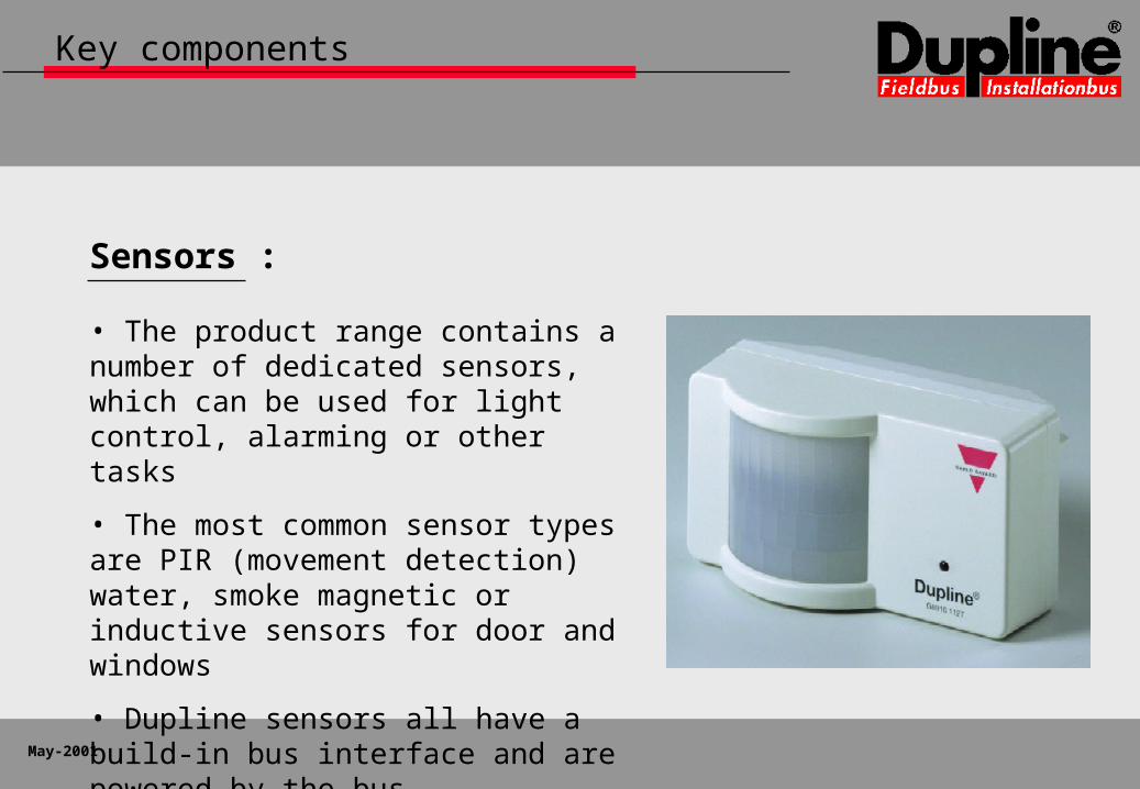
Sensors :
• The product range contains a number of dedicated sensors, which can be used for light control, alarming or other tasks
• The most common sensor types are PIR (movement detection) water, smoke magnetic or inductive sensors for door and windows
• Dupline sensors all have a build-in bus interface and are powered by the bus
May-2001
Key components
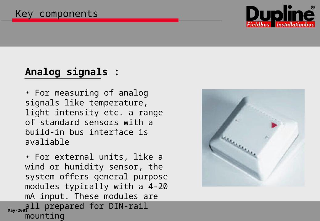
Analog signals :
• For measuring of analog signals like temperature, light intensity etc. a range of standard sensors with a build-in bus interface is avaliable
• For external units, like a wind or humidity sensor, the system offers general purpose modules typically with a 4-20 mA input. These modules are all prepared for DIN-rail mounting

May-2001
Key components
Human Machine Options :
• An advanced method to interact with an intelligent installation can be established by using an a text display, touch screen or a PC with a visualisation program
• A more simple method is to construct a graphically mimic panel with the range of cost-effective open PCB modules
• All signals in an installation can be accessed at any point without the need to reconfigure the controller or nodes
May-2001
Key components
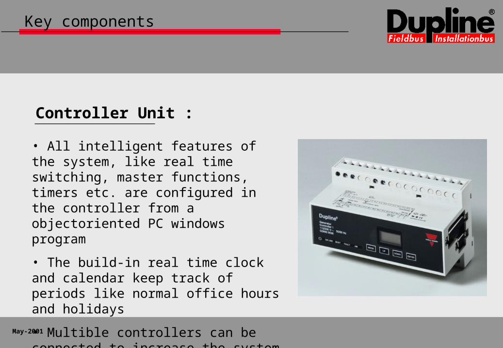
Controller Unit :
• All intelligent features of the system, like real time switching, master functions, timers etc. are configured in the controller from a objectoriented PC windows program
• The build-in real time clock and calendar keep track of periods like normal office hours and holidays
• Multible controllers can be connected to increase the system capacity

May-2001
Windows configuration

May-2001
Development strategy
Protection of the investment :
• The consequent use of the initial version of the Dupline communication protocol where all components comunicate in the same way means that new elements can be added to a existing system in a simple and standardised way
• A Dupline installation established 10 years ago can benefit from the newer options like a touch screen or a GSM communication module
• The system architechture and the capabilities of the controller allows the installationbus to operate as stand alone or as an integrated part of a larger system

May-2001
Dupline – a simple and flexible wiring concept
Focusing on the task of the installer
How is an installation realised ?

May-2001
An important issue
We claim that :
• The long-term success of an installationbus concept demands an simple and flexible wiring concept
• The fact that a special cable is not requiered for Dupline leads to real savings in the installation cost

May-2001
Installation phases
Specification :
• Prior to the actual planning phase, the consultant or system integrator must clarify the demands and functions which the contractor and end-user request the installation to fulfill and subsequently put this theese int a specification
• To carry out this job requires a general knowledge about the Dupline system characteristics and the available products
?

May-2001
Installation phases
Selection of modules :
• Select the appropriate modules from the product range and position them on a plan of the actual building layout
• Start with input modules like switches and sensors, since they occur in large numbers and are typically buspowered
• This gives a good overview of the range of the installationbus and will typically indicate the most efficient wiring layout

May-2001
Installation phases
Selection of modules :
• Next items to be added to the plan are the loads like lamps, outlets, roller blind motors etc. which are to be connected to the mains either directly or through an output module controlled by the bus
• The output modules can be positioned in one or more panels in central locations or at decentral positions close to the individual loads – or naturally also as a combination of the two methods

May-2001
Installation phases
Selection of modules :
• Finally the Dupline controller unit must be positioned
• It can be positioned freely and can be connected to the installationbus at any location in the installation
• In the present case, it is mounted in the main panel where the installation in the fictive building is divided between the ground floor and the first floor

May-2001
Installation phases
Cost-effective :

May-2001
Installation phases
Define wiring layout :
• A dedicated 2-wire cable be used for the Dupline installationbus throughout the installation. It can follow the natural routing of the power cables or an alternative routing where this is the most convinient
• An alternative solution is to use a unique pair of wires in the 230 VAC installation and realise the total system with only one type of cables / wires, as it is the case in most conventional installations
May-2001
Installation phases
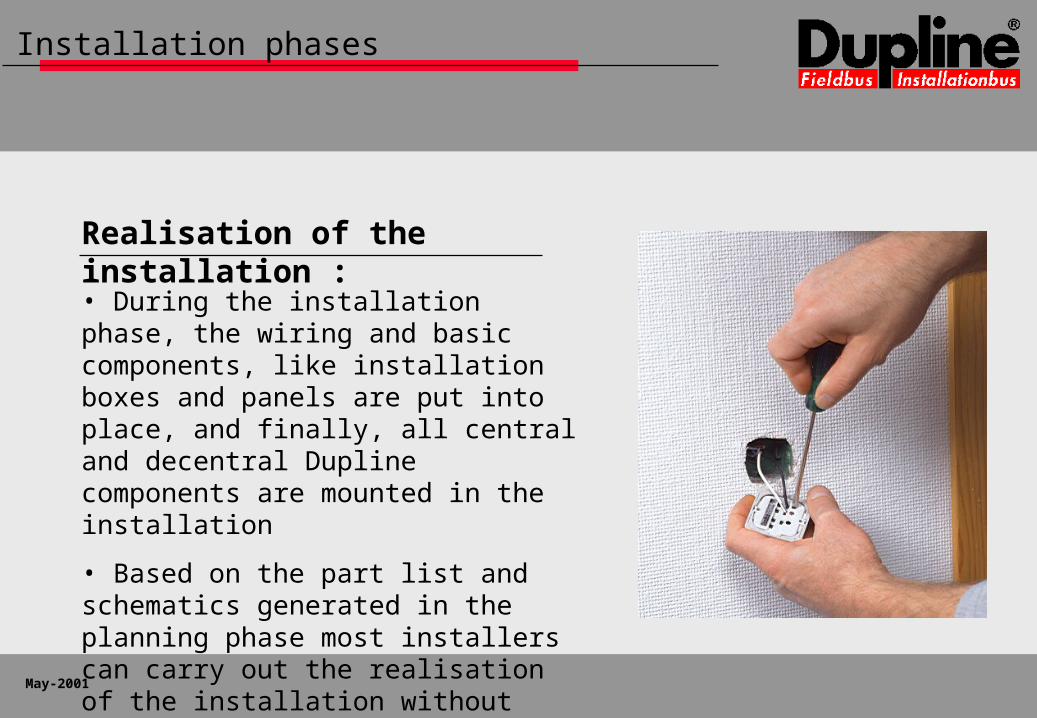
Realisation of the installation :
• During the installation phase, the wiring and basic components, like installation boxes and panels are put into place, and finally, all central and decentral Dupline components are mounted in the installation
• Based on the part list and schematics generated in the planning phase most installers can carry out the realisation of the installation without special knowledge of the Dupline installationbus

May-2001
Dupline – easy configuration step by step
The real test of any installationbus
What about the configuration ?

May-2001
System configuration
Overview :
• The system configuration phase starts when all the components are mounted at the correct locations and wired to the bus and external power supply if this is requiered
• The configuration of a Dupline system can best be described as a step by step procedure
• it primarily consists of the address assignment of in- and outputs on the individual bus components
• Followed by a definition and parameterisation of the desired function in the controller unit

May-2001
Configuration step by step
Grouping of components :
• The first step is to divide the components into groups, each of which is related to a particular function
• As an example the control of a unique lamp, heater or roller blind in a single room is regarded as group

May-2001
Configuration step by step
Coding of addresses :
• All output modules, pushbuttons, and LED´s etc. which belong to each group is coded to the same Dupline address
• This is done by means of the GAP 1605 coding unit
• For units with multible input or outputs it is possible to select and modify each one individually

May-2001
Configuration step by step
Test of coding and wiring :
• A test to check wether the component is wired and coded correctly can be performed on the spot by means of the GTU8 test unit
• This ensure that any fault is detected immidiately and eliminate the need for a fault-finding process throughout the network at a later state

May-2001
Configuration step by step
Configure the controller :
• The configuration of the intelligent functions in the controller is performed on a PC by means of a Windows-based SW with a graphically oriented user interface
• The process simply consists of defining a function for each of the used addresses, since the corresponding in- and outputs of the object / group has already been defined in the address coding phase

May-2001
Configuration step by step

May-2001
Dupline – a concept offering many solutions
The possibilities are many the choice is yours
What about integration ?

May-2001
Upper level communication
The demands :
• It is becoming increasingly important to link together the systems for lighting, roller blind control, HVAC and alarm and enable a central control and monitoring of the entire building
• Individual systems must be able to seamlessly exchange information via open protocols in order to create optimal solutions
• To achieve reliable and safe systems in larger buildings, it is requested that a system can be divided into sections which exchange informations but at the same time is able to operate independently

May-2001
Upper level communication
Our response :
• The demands has been driving the development of the Dupline interfacing capabilities and continue to do so
• An other driving factor is the integration of the new information technologies
• Mobile telecommunication is already an option and the further development will enable the Dupline controller to operate as a webserver

May-2001
Upper level communication
Solution concepts :
• The Dupline Installationbus has the flexibility to be used for small as well as large installations, and to be interfaced to basically any other top level system
• By combining the I/O-modules with the controller and interface modules it is possible to build a solution that fits the needs in the actual application

May-2001
Upper level communication
Stand alone system :
• A simple solution for external control and monitoring of a system is to use the GSM option.
• In case of alarm a SMS message is send to a mobile phone or the user can send a message to request or change the status of a signal in the system

May-2001
Upper level communication
Larger systems :
• Systems for larger buildings can be established by having a Dupline controller for each section linked to a Building Management System
• Up to 32 controllers can be linked and will automatically exchange information. If the communication line in one section is interrupted, the other sections continue to operate

May-2001
Upper level communication
A pure I/O system :
• The controller can also be used without the build-in intelligence and operate only as a interface unit
• This will convert the Installation bus to a pure I/O system which can be used by a DDC or PLC from leading manufacturers like Siemens, Honywell, Johnson Controls etc.

May-2001
Dupline partners
Concepts powered by Dupline :
• Promoted as ELKOMATIC in Norway and Sweden for a period of more than 5 years
• Presented on the Light and Building fair in Frankfurt 2000. Doepke also manufactures Dupline products used by ELKO and CG
• Introduced by Carlo Gavazzi in Denmark 2001. The concept includes a end-user oriented homepage and brochure as well
www.doepke.de
www.smart-house.dk
www.elko.no /.se