may/june 2002 gear technology · the shop floor. on the fly' to the pr[mar universal gear...
TRANSCRIPT
Now you have singlesource access to everythingfrom Double Flank Roll Testers toaccurately identify proce 5 variations onthe shop floor on the fly to the PR[MARUniversal Gear Inspection System thelatest in single setup complete measuringtechnology
Call today or log-onto learn more bullbullbullwww-Ieason com
Now there are nolimits to how good aU
iiiiiiiiii~our gears can beChances are theres a Gleason Malumetrology product for any and all ofyour gear and gear tool measuringrequirements bevel or cylindricalinternal or external plastic orformed hobs or shaper cutters
1000 U niversity Ave bull po Box 22970Rochester NY 14692-2970 USA
Phone 585473-1000 Fax 5854614348Web site wwwgleasoneom E-mail salesgleasoncom
THELATpound5TINNOVATIONfNHOBBINGSUPERIORQUAUTY SERVICEAND DfllVER Y
MAVJUNE 2002 The Journal 0 Gear Malzuacturing
FEATURES
FOCUS ON GEAR DESIGN
21
DEPARTMENTS
Clrver art CQurtesy D StepanLunin Chesapeaku VA
Carbiide Hobbing Case StudyA gear manufacturer starts from scratch with new technology 12
Gear Oesiign Special Section 21
Optimizing IPlastic Gear GeometryAn IntroductiontD GearOptimizat~ionA close look at working tooth depth and other parameter 22
Program for Involute Equation to Develop Spur Gears on PmE SoftwareA program for modeling spur gears with profile shift 27
lnereased Load Capady of Worm Gears byOptimizing the Worm Wheel Bnm~eA study of bronze alloy content 33
IPublisher~s Pagelndu trial Evolution 7
Revo~lutionsIce-blast gear cleaning 9
Industry NewsWllats happeningin the gear industry 18
TechnicalCallendarDOIlI mi s these important upcoming events 31
IProduct INewsThe latest product for the gear industry 38
1CD~ROMIIBUyersGuide FREEListing FormsSign up for fr~e listings in our 2003 directory 40
Advertiser IndexNEW Phone numbers and web addressesto make it easier to get information 44
IClassiliedsServices Help Wanted websites and more 45
AddendumFrom Rus ia With Teeth 48
Ultra Precise Hobs RUSSELLtlOLBROOKampHENDERSONINC
Accu racy Class MA AA AMaterials CarbideBridgeHSS
Tedmology DryHigh SpeedHard HobbingRange 10-500 Diametral Pitch
STOCK AVAILABLE17~17 Route 2Q8 North FiiorrLawn New Jersey 07410Telephone 201-796-5445 Fax 201middot796middot5664~ MEMBER OF ~WMII GROuP
Visit our website at httpwww_tru-volutecom
__ tnchldngtlnlla atamentAtrows latest success was utilizing ourstate-of-the-art technologies to design thegear tooth geometry and to manufactureall bevel gears in the PTOampAGB forPratt amp Whitneys PW 6000 engine
2301 Curtiss Street Downers GroveIL 60515Tel (630) 969middot7640 bull Fax (630) 969-0253
wwwarlOwgearcom
4 MAYJUNE 2002 GEAR TECHNOLOGY WWWgeartechnolagycom wwwpowertransmlssiancom
GEAR TECHNOLOGY_________ TIrJondvffJt(tll-LltflU~rinampl_ I
I
EDITORIAL I
Publisher amp Editor-In-ChiefMichael Goldstein
Managing Editor William R Stott
Associate Editor Joseph L Hazelton
Assistant Editor Robin Wright
Editorial Consultant Paul R Goldstein
TechnicaI EditorsRobert Errichello
Don McVittieRobert E Smith
Dan Thurman
ARTArt Director Jean Bartz
AOVERT1SINGAdvertising Manager Patricia Flam
Advertising Coordinator Gladyce J Cooper
Cirenlation Coordinator Dina Krauss
INTERNETWeb Developer Dan Mackenzie
Gear Industry Home PageThI SalesPatricia Flam
David Tornalis
powertrallsmissionCOIIItrade SalesMichael A Gianfrancesco
RANDAU PUBLISHING STAFFPresident Michael Goldstei 11
Vice President Richard GoldsteinController Michael Grafman
Accounting Dianne Johnson
Phone 847-437-6604E-mail peoplegearteclmologycom
Web wwwgeaneehnelogycomwwwpowertransmissioncomBPAW
VOL 19 NO3GEAR TECHNOLOGY The Journal or GeuMailulat-tln~ (fSSN 0743-(858) is published hirnonthlyby Randall Publishing Inc 1425 LUi1t Avenue PO Bo1426 Elllt Grove Village IL 6IJO()7(847) 437-6604 Coverprice $500 US Periodic I postage pnid at ArlingtonHeights [L and at additional mulling office RandallPublishing makes every effort to ensure thai the proces-seidescribed in GEAR TECHNOLOGY conform to sound engi-neering practice Neither the authors nor the publisher can beheld responsible for injuries susruined while following theprocedures described Postmaster Send address changes toGEAR TECHNOLOGY The Journal of Go urManusacun-ing 1425 Luru Avenue PO Box 1426 ElkGrove Village IL 6IJO()7OConLont copyrighted by RAN-DALL PUBLISHING INC 2002 No pan of Ilti publico-lion may be reproduced or transmitted in un) form or by anymeansc electronic or mechanical including photocopyingrecording or by uny ill format jon storage and retrieval sys-tem without permlssron In writing from me publisherContents of ads arc subject 10 Publishers approval
NACHiNACHI MACHINING TiECHNOIOGY co
Globo I ExpertiseFor All Applicotions-_
See Us atBooth B6953
with continuedI e a die Irs hi p Combining over 140 years of processmachine and tool experience enablesNachi Machining Technology Co tomaintain industry leadership by providingcustomers with the best practicesmanufacturingl solutions
Broach and GeaTFinishing ProductsBroaches
ConvenllonalGulletSpmBlQlldeSplineBlind Spt(IIJ
FuU-FonrtTlJIlslonedDrawampltSatICePo(
Fir TmfJShavtrrQ CutlersRalJDlesHobsShape CUtlllfSRoll Formm[1 Racks~BumiSflltlQ Tools
let us help you with all of your Broachingl
Gear Shaving Hobbing lRollingl Gear HOllingand Tool Sharpening needs
INACHI MlACHIINIIING TeCIHNOlOGY CO17500 Twemy-Three Mile Road Macomb Michigan 48044-1103Phone (586)-263middot0100 Fax (586)-263-4571 WWN nacturrsccom
MACHINE Up To
MORE PARTSPER HOUR
Dura-Bar Plus is a new engineered ironthat machines better than carbon and alloysteels and better than competitive grades 01
continuous cast iron
New amp Improved Dura-Bar Plus gives youA LOWER COST PER PART bullbullbull
PLUS - MORE PARTS PER HOURDecrease cycle timeIncrease productivity
PLUS - LONGER INSERT LIFEReduce your downtime fortooling changes
PLUS - A DEFECT-FREE MATERIALQuality guaranteed
New Dura-Bar Plus is available in gray and ductileiron grades and in a wide variety of sizesand shapes For more information see
web site at wwwdura-barcom
Or cani-800-BAR MILL(1-800-227-6455)
AND SAVE MONEY WITIINew Dura-Bar Plus mE LATEST
IN ENGINEERED METAL TECHNOLOGY
Continuous Cast Iron Bar Stock
2100 West Lake Shore Drive Woodstock II 60098-69111-800-BAR-MIII bull 815-338-7800 bull FAX 815-338-1549 E-mail salesdura-barcom Internet wwwdura-barcorn
IPUBUSHERS PAGE 1-----------------
he gear jndustry m(e any Olher is constantly chang-ing Companies vie for customer resources
employees and time They come go and shuffle for
po ition Usually the changes are small affecting
only a few companies But sometime many
changes happen at once and when those changes arc large it
Tcan seem as though an earthquake ha struck and transformed
the landscape of the industry
I feel as if such an earthquake ha recently truck TwO
month of tumult haveleft us with a different gear industry than
we had the last time m wrote thi column In particular two old
friend have dosed their doors Also weve seen realignment
among some of the key suppliers
We were addened to hear that one of the gear industrys old-
e I upplier -Fellows Corp-was forced [Q clo e its doors in
February Located in orth Springfield VT Fellows served the
gear industry for more than 100 years It was founded in l 896
by Edwin R Fellows the inventor of the American version of
the gear haping machine
Fellows cia ed when it parent company the Goldman
Industrial Group filed for Chapter 11 bankruptcy protection
Goldman Bridgeport Machine Co continues to operate but the
groups other sub idiarie Bryant Grinder Hill-Lorna ]nc JampL
Metrology and Jones amp Lam on Machinery closed along with
Fellows Those dosed subsidiaries are now up for sale
Hopefully someone who wants to continue making gear
machine tool will buy Fellows so that the name doesnt fade
into obscurity
Shortly after we heard the news about Fellows we were
shocked to learn thai one of the gearindustrys oldest and most
re peered manufaeturers-e- The Cincinnati Gear Cov-had also
dosed its doors Cincinnati Gear was founded in 1907
Detail about Cincinnati Gear do ing have been sketchy
and the company may yet emerge in some form from its diffi-
eultie The company had been having troubles like much of
industrial America and it laid off a number of workers over the
last year But those troubles turned to crisis with the bankruptcy
of nron Corp whose wind turbine division was a major cus-
tomer of Cincinnati Gear On Feb 28 incinnau Gear was
forced to layoff most of its employees
According to a letter we received from the company in late
March Cincinnati Gear is working with a management consult-
ing firm (0 explore all available option [Q maximize the value
of its business and assets What this mean at this time i
unclear but what is clear is
that if Cincinnati Gear
emerges from these diffi-
culties it will be a much
leaner company than it once
was
Weve all watched the
manufacturing economy
struggle over the past two
years Weve seen it COIl-
tract as Americans have imported more of the manufactured
goods we used to make for ourselves Its no surprise then that
some gear industry companies are having problems and have
been laying off employees over the past couple of years
Hopefully the companies that urvive these times-c-perhaps
including ellows and Cincinnati Gear-will be in much better
position to take advantage of the market when it improve
In the face of slower manufacturing actjvity plana are clos-
ing and new foreign suppliers from places like India Pakistan
Poland China Taiwan and South Korea are taking their place
This process is not unique tothe United States England the
birthplace of the Industrial Revolution is seeing an exodus of
manufacturing at a frightellillg rate Thi proces is 0110 occur-
ring in Germany and Italy With the possible exception of Spain
Western Europe manufacturing i contracting at different rates
ill different countries but contracting nonetheles Japan is also
seeing manufacturing flee to lower-cost areas We all still clothe
de igning engineering and marketing bur increasingly we are
becoming importers and a semblers and less manufacturers
In addition to and maybe as a re ult of the changes Ive
wwwpowerlrsnsmlssioncom bull wwwgearlechngycom bull GEAR TECHNOLOGY MAYJUNE 2002 1
stop sourcefor all yourgear-makingrequirements
Aero Gear line
bull Precision carburlzsdgears housings andgearbox assemblies
bull New flowline productionbull Supplier to leading
aerospace manufacturersbull Tolerances to AGMA
Class 12bull Design asslstance
availableFor more information contac
Aero Gear Inc1050 Day Hill Ad Windsor CT 06095Tel (860) 688-0888Fax (860) 285-8514
1509002CERTIFIED
lS90001
____ PUBLISHERS PAGE _
already mentioned the gear industry has also seen a IOl of shift-
ing among the major machine tool suppliers For example
Bourn amp Koch Machine Tool Co has purchased a controlling
interestin Roto-Technology Nachi Machining Technology Co
has promoted Butch Wisner to president and CEO MampM
Precision Systems Corp has named Douglas Beerck its vice
president of sales and marketing In the United Kingdom
Dathan Tool amp Gauge has purchased David Browns gear cut-
ting tools division
Perhaps the most significant news was the announcement
that Star Cutter Co has left the Sigma Pool alliance to consoli-
date its cutting tool sales operations with that of SU America
Inc With this new alliance the SU group has quickly broad-
ened its product offerings joining Gleason Corp Mitsubishi
International Corp and the remaining Sigma Pool brands of
Liebherr Lorenz KIingelnberg and Oerlikon as full-service
suppliers
In most industries the major suppliers compete for the bulk
of the industrys business like hungry sibling around the din-
ner table Like older brothers the bigger suppliers take the
lions share while the smaller suppliers have to ettle for whats
left over In the gear industry another hungry kid has arrived at
the table at a time when theres less food to go around
Adding another major supplier will result in fierce competi-
lion herein the United States for machine tool and cutting tool
sales meaning those suppliers will find it harder to maintain
profitability The result is that you the gear manufacturer will
have more choices among suppliers and technology-probably
at lower prices
All of these changes should make this years IMTS very
interesting I will be watching the dynamie of this increased
competition As we emerge from the manufacturing recession
1 can only gue s that the e competitors will be damming for
your business
Michael GoldsteinPublisher and Editor-in-Chief
8 MAYJU NE 2002 bull GEAR TECHNOLOGY wwwgeartechnoJogycom bull wwwpowertrensmtsstoncom
REVOLUTIONS
chips instead of using solvents or water-
based cleaning solutions The systemwas developed by Universal lee Bla t
Inc of Kirkland WA um manufacturesice-blast machines for commercial and
industrial useThe sy tem was installed for produc-
tion cleaning at Fords transmission gearplant in Sharonville OH
With this sys tern ice chip aresprayed through a nozzle at a pressure
ranging from 65-75 pounds per square
inch Hitting a gear the chips deform undcreate a crubbing action displacing the
gears contaminants After impact thechip melt into water and wipe away thegears debris and contaminant
The chips are created in a refrigerateddrum The drum uses ordinary tap water(0 form an ice layer The layer thencracks into small chip which are movedinto a stream of compressed air andsprayed through the sy terns nozzle
You have an environmentally friend-ly proces says Tony Tonello [8
vice president of marketing and engi-neering sales You save the cost of sup-plying the e soap or solvents as well as
the cost of treating these solvents in thewaste stream
As for its effectiveness the cleaningsystem was placed online at the
Sharonville plant ill March The new sys-tem ha been operating 16hours a day
five days a week cleaning the input
Cleaning Gears with Ice Chips-and Nothing Else
Residue from cleaning solutionYou wash your gears a best a you
can but its there Then il gets onlhe
master gears of YOUf gear checker After awhile enough residue collects on the
master gears that it throws off yourchecker which tart rejecting goodgears
Your solution Stop the checker punout the master gears clean them put
them back inthe checker and recheckyour rejected gears
Not much of a oiution-especially
when you have to do it every couple ofhours That been the problem at several
Ford Motor Co plants for many yearsFord bas III po ible solution
though=ciean gears with ice chipsThe solution is a new sy tern that
cleans gears by spraying them with ice
Universal Ice Blast Inc of Kjrkland WA concetvedaml designed a Imachine Ihlllcleans gears byspraying lhem with ice chipsTDe machine dOllSolluse solvents or water-based CleaningDlu1iollS
wwwpowrtransmlssoncom bull rwww119srtchnoiollycom bull GEAR TECHNOLOGY MAYJUNE 2002 9
REVOLUTiIONS
were really hoping for thats a biggie
says Mike Gourlay a Ford mannfacrur-ing engineer
Gourlay is responsible for the finaldrive and transfer gears used in the FordPocus transmission
With the new system though Fordmust add the ru t inhibitor to the gearsafter theyre checked using a machinebuilt by UlR
Other companies also make systems
that Clean gears Located in CinemnatiOH Ransohoff Inc makes water-basedgear-cleaning systems But ToneUo
says urns system at the Ford plant isthe first application of ice blasting forcleaning gears
A 17-year Ford employee Gourlay
has worked with gears for 10 yearsBefore the urn system he knew of no
viable alternative to the plants old gear-cleaning system
The plant also checks the VIB sys-tems effectiveness at achieving a setlevel of cleanliness The plant takes sam-
ples of its cleaned gears and checks theircleanliness with a second washing The
samples groups of five gears arewashed with an inert liquid The liquidresulting contaminant level is then meas-ured The level must be 25 milligrams
or less for each groupEarly tests showed the system met
that requirementUsing a six-sigma approach the
plants data has indicated the um sys-tem would successfully clean more than99 of the gears
to MAYJUNE 2002 bull GEAR TECHNOLOGYmiddotmiddot gartechnotogycom bull wpo errsnsmissioncom
water and a soaplike cleaner and includ-
ed a rust inhibitor The gears residue ofcleaner and inhibitor would build up onthe master gears in the end-of-line gearchecker The build-up would result in
30--35 false rejectsReinspecting rejected gears uncov-
ered the good ones and raised the passrate to 95
With the new system the first-timepass rate is about 98 Thais what we
transfer gear used in the transmission of
the Ford FocusThe input transfer gear is a helical
gear with an internal spline that hasundercut The gear arrives at the cleaning
system straight from grinding so gearand spline have swart anthem 111esys-tem has a fixture that lifts and rotateseach gear so ice chips can reach aLI thegears surfaces
The old system cleaned gears with
AVV Systems Go announces that it is now amanufacturing source 01 spiral gear roughingand finishing cutters and bodies
We also can manufacture new spiralcutter bodies in diameters 01 S through 12at present
AJIN can also supply foughing and finishingcutters for most 5--12 diameter bodies
Whether its service or manulacturing con-sider us as an alternative source lor cuttersand bodiesYoull be in for a pleasant surprise
NEW Hob and Shaper Cutter Resharpening[s now available at AW Systems Companymiddot Royal Oak Michigan 48067
Tel (248) 544middot3852 bull Fax (248) 544-3922
Universal Ice Blast built the rna china iits firstice-blaS1 Igear-cleaning system lor IFordlMotorCo The FDrd plant in SharDnvilie OH is using themachine to clean the inputtransfer gellrmiddot used in(lie transmission of tile FordlFocus
REVOLUTIDNS II _
FOld ha nt accepted the sy tern yetbut plans to use it fer three monthsmroug1iJthe end of May II will then com-pare performance data from the systemflrst three monmsand the old systemsla t three months to make a final evalua-tion and decide whether 10 accept lhesystem
I think it represents a very big poten-tial to olve a long- tanding problem
Gourlay ays But I gtre s-being anengineer-TID reluctant to say wereucces ful until 1 see the data
But were expecting 10 be uecessfulThe y tern con i I of a gear-dean-
tng unit and an ice-rnaking unit TheFord y tern gear-cleaning unit is 8 feetX l Zfeet and i 12 feel ta~1The ice m k-ing unit i 4 feet X 6 feet and i 5 feettall
The Ilwo unit are connected by anindustrial hoseo the ice-making unucan be as milch as I 00 feet from the gear-cleaning unit Tonello ays the hose letsa company place the ice-making unit in adead space in its plan
The Ford system Ire about 20 gal-lons of water an hour But 50 of thaiwater evaporates The compressed airthat accelerate the ice chips creates awind thai causes forced evaporation ofthe re ulting droplets
Tonello compare that forced evapo-ration to a man rubbing his wet handtogether in front of a warm fall
So gear manufacturers have to dealwith about 10 gallons of water an hour
A fIllly automated ice-blast ySICm-able to proce a gear every 2() ec-
ond -cos Is between 25()O and$300000 An air delivery systemincreases the systems cost by$15000- 40000 depending on the airpre ure required
Manual system that handle fewergears stan at 50000 apiece
The CC)ts assume air and water willbe upplied by the purchasing compa-
niesGourlay hope the sy stem will reduce
the checking of master gears Itojust oncea hifi at the tart of a hift just 10 makeure lJJeyre OK-that the sy tern get
wwpoIrnllmiuloncom bull IIIl1ft11rcllnoloIlYcom bull GIEAR TECHNOLOGY bull MAVIJUINE 2002 11
rid of the problem of good gears beingfal ely rejected
Thats whal ] thought was the big
carrot G urlay say Thisreally doeshave the poteruial to deal with a problemthai weve had for a long lime
Tell Us Whal You Think Vish www(lNJtflChnologycomlobull Rale Utis articlebull Request more infonnationbull Comact die companill mentionedbull Make 8 luggestionOr call (1M7) O7-8iIM talc II1II IIIDII lllillnl
Ihisallticle was 61Spuhlisibedat the AGMA
2001falltechnicalmeeting
Printedl with permissionof the copyright hoIder
the American GeariManufacturers
Association 1500 KinglStreet SUite 20ill
AIexandria Virginia 22314Copies of the Ipaper are
availabletromthe assecletion
Statements presented linthis paper are those of theauthor and may not repremiddot
sentfhe position or theopinion o~the American
GeaJ ManufacturersAssociation
and sometimes conflicting recommendation 011
these details This is why many companies man-ufacturing in small to medium lot sizes have notrushed to implement carbide bobbing Also somecompanies tried and then abandoned this technol-ogy altogether
This article is a case study featuring one manu-facturing cell solely implemented with carbidebobbing technology The annual output is250000-300000 gears with an average just-in-time lot size of about 200-300 gearsApproximately 150 different sizes and pitches areproduced with an average of four setup changeover two shifts Most of the gears are finish hobbedto AGMA 9 quality level The pitches range from12-64 DP
Carbide Hobbing Case StudyYefim Kotlyar
(out of rive) hobbing machines had an automaticshifting feature There was not precise control onhob positioning relative to the workpiece or thebob shifting di lance The e machines were inconstant need of maintenance
Fixlllring and Automation Only twomachines in the cell had automatic loadersFixturing and automation documentation was notreadily available Some of the fixture items werereverse engineered and not always compatiblewith each other Our company relied mostly on the
Figure 2-COSI breakdowlI by percentage for lIew experience of setup people This led to a widecarbide hobbilg cell variation in setups fixture and cutting conditions
12 MAYJUNE 2002 bull GEAR TECHNOLOGY wwwgllsrtecllnologycom bull wwwoowertrsnsmisetoncom
The successful performance of carbide hob-bing is predicated on various contributing factorssuch as machine fixture blanks hob mainte-nance and process management systems Thesefactors will also be discussed
Application and Historical PerspectiveBodine Electric produces a large variety of
parts with gearing elements-spur and helicalgears and shafts solid- and bore-type pinionsworms and worm gears For the introduction ofcarbide hobbing we decided to select the natgear family because of its large volume
MaCilies Initially we had only outdated hob-bing machines in the flat gear cell The averagemachine age was 20 years The use of longer- and
L- --J higher-performance hobs was limited by theflat gear j machines rpm and shifting capability Only two
I
IntreductlonBodine Electric Co of Chicago a has a 97-
year history of fine- and medium-pitch gear man-ufacturing Like anywhere else traditions oldsystems and structures can be beneficial but theycan also become paradigms and obstacles to fur-ther improvements We were producing a highquality product but our goal was to become morecost effective Carbide bobbing is seen as a tech-nological innovation capable of enabling a dra-matic rather than an incremental enhancement toproductivity and cost avings
Nowadays no one denies that carbide hobbingis feasible Many questions remain howeverregarding the best applications carbide materialhob sharpening coaling and recoating hob han-dling hob consi teney optimum hob wear bestcutting conditions concerns for the initial cuttingtool investment and production cost In short thedevil was in the details The industry had few
LSL USL
Tolerance -
l 6 Sigma
Figure 1 Process variatioll for thefamily was out ofeomrol
Cutting Tools A long-standing tradition infine-pitch gear manufacturing wa the use of 0-
called quare hobs made out of high-speed steel(HSS) Use of carbide and longer hobs waslimit-
ed by each machines rpm capability and shiftinglength re pectively
Cutting Condjtions Our practice was to usevery conservative cutting conditions that were out-
dated Different machine had different limitationswith re peel to rigidity and rpm capability The per-fonnance of each machine was not monitored Thecutting conditions and cycle times could vary
depending on the setup person machine inspection
reo ults and cutting tool used at the timeBtallks All blanks were outsourced The sup-
pliers would grind one face of the gear blank enabling us to stack three to five parts per load
during the bobbing proces De pile thiseffort the bores quaHty and face paralleli m wereincon isteru
OutsorlreillgIn addition to five machine mak-ing flal gears in-house we were outsourcing hob-bing and skiving at an annual cost of $281000Adding to hat the annual blanking outsourcing of$563000 our total flat gear outsourcing cost came
to $844000 Other concerns with outsourcing werequality and on-time delivery
Quality~ The flar gear proces variation was
out of control as showa on the graph ill Figure 1Although we had extremely knowledgeable peo-ple who were able to produce quality partsde pite u iDg old technology many etup wouldturn into development projects which took its toll
on our productivity and profitabilityThe high quality of the product wa main-
tamed at a co t Extra non-value-added tep of100 inspecting and orting were nece ary]oshortv the co t of flat gear manufacturing was I
high We wanted to improve the proce andreplace product control with process control
P~(Jductillity Cycle times were very longFrequentlym achieve the desired quality setup
personnel would use more con ervative cuttingconditions thu further increa ing cycle timesand reducing productivity On average there wasless than one etup per machine per day Theinexpensive conventional off-the- helf quare
hob had to be re-sharpened quite frequently thuseli rupting production flow Lean manufacturingstresses the importance of just-in-lime manufac-
turing and continuous reduction of work-in-progress This lead to smaller lot sizes and
greater setup frequency per dayIn summary we had an abundance of opportu-
nities
Quality Improvementbull Process capability improvementsbull Further tightening of the tolerances to produce a
higher quality product
Productilvity Improvementsbull Reduce cycle times and increase productionwith the same number of peoplebullReduce setup time
bull Reduce proce s debugging timeCost lmpJIOvementsbull Cost reductions as a result of productivityimprovementsbull Lower cutting tool cost per gear or keep it thearne as HSS
bull Reduction in rework costAdditional Capacitybull Skiving Capabilitiesbull Reduction in outsourcing
Considerations fOIi New TechnologyWe could have benefited by improving the
process in small incremental changes Someexamples are reworking the machineshuying
better cutting tools improving the fixture buy-ing better blanks and even stressing greater con-
trol of OUi processes These would have all
brought some semblance of succe nnetheless we felr tilat we needed drastic
rather than incremental improvements to bringthe process under control and achieve co I reduc-tion This is why we decided to blow up every-thing investigate new carbide bobbing technolo-gy and bring a new pirit into the factory
At the same time we wanted to bring in tech-
nology that would work from the onset We want-
ed to be conservative in our estimate making
sure that there would 1I0t be exce ie proce
Vefim IKotlyaris Iht gear technologv andprocessing I1wlIllger atBodine Electric Co tocatedin Chicago lL For man
Ilion 20 years he worked indijferlfII capacities on rhedevelopment and implemen-tation of various gear mallumiddotfacturing and inspectiontechnotogies He is also alt
autnor of IIUll anicle ongear-related subjectraquo
1OI101101pOWflrtransmisSloncom bull middotwwwgurllJclln0ogycom bull GEAR TECHNOLOGY MAYJUNE 2002 13
Figure 4--New syste11Iincluded jlexible automa-tion with gall try loader
Figure 5-PrecisiDlI ql~ick-callge jace-dampLng[ixlllrll for damping more than 150 types oj partsdebugging So we decided that a test would be theideal first step toward a successful implementa-tion of new carbide bobbing technology
Robbing TestTest Objectives
bull To learn more about potential challengesbull To understand tile pro and cons of carbide hob-bing as applicable to our pitch and size ranges
bull To have the process debugged prior to purchas-ing the machine
bull To specify the machine acceptance criteriabased all challenges experienced during te lingo To compare machine suppliers
bull To start developing carbide bobbing sUpjXlrt ystemsWe anticipated a need for a better engineering
support system as well as a simpler more disci-plined process monitoring system that would giveus reliable feedback We knew that after the major
investment the flat gear cell would be crutinizedTest Filldingsamp Potelltial Clzallellgeamp
bull This is an emerging technology although ilstarted 30 years ago
bull Many tried but abandoned carbide hob bing bull Greater engineering support will be required There was no industry consensus on recommen-
dationsbull The mistakes are much more expensivebull The tool cost per gear was an unknown factorbull The initial cutting tool investment is muchgreaterbull We found three vendors all capable of achievingour tighter quality requirements
bull The selection was based on business reasons
rather than technical reason Dry or Wet-That Was the Questioll We test-
ed both wet and dry bobbing Eventually weselected the wet process because we felt it was a
safer approach to the introduction of new tech-nology At that time our perception was that drybobbing required more engineering involvement
and RampD Each pitch and size had to be tested
and fined-tuned for optimum hob geometry and
cutting conditions The machine was 10 be placed
in a gear-manufacturing cell that was producing
more than 150 different sizes and pitches So the
testing and development of every part couldbecome quite overwhelming Also we experi-
enced less tool wear with wet carbide hobbing
Nevertheles we acquired a dry bobbing optionThis was just in case the process is further devel-
oped and better information about dry bobbingbecomes readily available
Best Carbide Hobbing AppiicatillTls It seems
that the fine- and medium-pitch fini h hobbedgears are the best candidates for the carbide hob-
bing technology The finish bobbing feed rate isrestrained by the feed scallop limitations thusproductivity improvements cannot be achieved
by increasing the feed rate Another option for
productivity improvement-multistart hobbing-cannot be employed for precision hobbingeitherThe only viable option for productivity improve-
ment was increasing the hob speed
Support Systems Needed We came to the con-
clusion that in-depth engineering support systemswould be needed for successful carbide hobbingMistake with carbide hobs co t much more thanthey do with traditional HSS hob
Those systems would include
bull Databa e with simple means of extracting setupdata for every partbull Ease of database maintenance
bull A detailed hob monitoring sy tern which isunprecedented in a production environment
bull Detailed production and value-added monitoringNew Hobbing Technology
The 1itialnvestment After conducting tests
and selecting a vendor we purchased the equip-ment with co t distribution a hown in the graphin Figure 2 The total package included machine
automation quick-change fixture and carbidecutting 100Is In addition we purchased a newturning machine and developed correspondingsupport systemsNew CNC Hobbing Machine Highlights (Fig 3)bull 8 CNC axes including gantry
bull Higher cutting speed available14 MAYfJUNE 2002 GEAR TECHNOLOGY bull wwwglUlrt~chnologycom bull wwwpowerlransmissioncom
bull Longer hob shifting capabilitybull Capable of wet and dry hobbingbull Hydraulic hob arbor clamping bull Skiving capabilitybull Flexible Automation with Gantry Loader (Fig 4)bull Six seconds loadunloadbull Capable of handling roth bore- and haft-typepartsbull Large uruIoad Image capacitybull OC controlled loader po itions
The Fixlunng Because the fixture quality iscritical to process capability we acquired a preci-ion quick-change face-clamping fixture (Fig 5)
The fixture had a modular de ign for more than150 parts The design was al 0 based on the COD-
sideration of clamping the parts as close as po i-ble [a the cutting action At rno I there are threefixture items that need to be replaced when chang-ing over from one part to another backing clamp-ingand arbor
The number of parts per load was reduced 110
two CNC hobbing diminishe the effect of tack-ing gears per load because a) a higher feed ratecan be used during the hob approach travel and b)
the loadunload time is minimal lricidentally II
smaller number of parts per load improved thegear quality AI] fixture drawings were computer-ized and became a part of setup documentation
Tie Blanks A turning process was developed011 a newly purchased CNC lathe It providedOO(X)2- 00005 face parallelism and bore-to-faceperpendicularity This kiad of turning qualityeliminated the need to grind gear face In fact theblank quality coming out of our CNC lathe wamore consi tent than our outside-purchasedblanks having the one face ground
The new turning machine also made it possibleto tighten the tolerance of the bore size The lathewas strategically placed ne 1 to the CN bobbingmachine to enable one-piece flow
ClUbiLle Cutting Tools We started with K-grade hob and TiN coating (Fig 6) However 111addition we purchased a few P-grade hob with-TiAIN coating (Fig 6) Carbide hobs wererun at600 surface feet per minute (SFM) of circumfer-ential speed The feed rate was just 3_ conserva-tive as in the case of HSS nabs The conservativefeed rates were necessary becaa e of feed callopdepth limitations The first peek at the carbide hoblife provided impressive results The first runresulted in 765 parts without a hob changeMaking 34 times as many gears meant thatthetool cost per gear would be spproxirnately thesame as in the ca e of HSS We were glad that wewere able to reduce the cycle time threefold while
Figure 6-Kgrade j- -coated carbide 1mb (left) and P~grad liA1Ncoaledcarbide 1I0b
Hgulle 7-Coalilg fractures call eonoibiulaquo to poorflob performance Multiple coaJilJg layers chipped01 lIe outer surface (top)wllile tile lower coatinglayer~have remained intact (bottom)
enjoying approximately the same tool co t pergear (Note that carbide hobs were three to fivetime more expensive when compared to tradi-tional square HSS fine-pitch hobs) Howeverwe continued to u e the same hob Before we sent
it for harpening we achieved the hob lifeimprovement of elevenfold (2639 gears) a com-pared with HSS quare hobs
After the first hob harpening we realizedthere was work 10 be done in mastering this tech-nology Lesson 1 learned Without recoating thehobs bullthey failed mi erably We also learned thatwith respect to the cutting tools our limited initiallest provided few comforting answers Recom-mendations from hob uppliers and machinebuilders continued to be inconsistent and at timeseven contradictory We till had a lot of questionsShould we use P-grade or K-grade What was thebest coating for our application What was the
wwwpowertransmssioncom bull wwwgmiddotS8rlechnologycom bull GEAR TECHNOLOGY MAYJUNE 2002 15
Gear Center Line
I Roughing--I ZoneGenerating __
Zone
Hob Length
Figure Sa-Wear distributioll OIl a shorter hob
Hob Wear
LAHob Wear Distnbution
Hob Wearj -----
_ Roughing _ Generatins__ ShiftingZone Zone Zone
Figure 8b- Wear distribulioll(HI a lmlger hob
Gear Cen1er Line
Hob Wear Distribution
near the bottom of the illustrationWe have yet to find overall consistency in hob
performance Although the greatest performancefactor is probably how people use the hobs othercontributing factors are sharpening coating qual-ity and the ability of the coating layers to stick tothe previous layer
Every single carbide hob has a history work-sheet Currently we have more than 80 carbidehobs that service our flat gear cell Every time thehob is used the setup people record the date thegear number and the number of gears bobbedThe rest of the worksheet is calculated automati-cally One of the important characteristics ismaterial removal per cutting edge of the hob
Hob Lelgth Significance In addition tochanging the hob material to carbide we intro-duced longer hobs This further reduced the cut-Ling tool cost per gear and reduced downtimecaused by hob change because longer hobs makemore gears per sharpening Conventional think-ing implies that the improvement would be pro-portional to the hob length increase
However in reality the improvement is pro-portional to the shifting increase Figure 8a and8b show the load and wear distribution 011 shortand longer hobs Short hobs may have little or noshifting length available Frequently a small hoblength increase can result in manyfold hob per-formance improvements
CdtilJg Tools Cost Reduction A conservativeestimate of per-gear tooling cost reduction isclose [0 threefold (Fig 9)
Support SysCemsTo understand and maintain the carbide hob-
optimum wear What were the sharpening bing process our company introduced a systemnuances (ie edge preparation) When was the for monitoring process performance A setupright time to strip the coaling and was itpossi- database wa created to include all process docu-ble What was the hob life and tool cost per gear mentation such as fixture cutting tools gearWas there any predictability in carbide hobbing parameters cutting conditions cycle time and
Figure 7 is an example of one of the many other necessary setup information For everychallenges that we experienced Coating fractures setup the database query creates a single sheet ofcan contribute to poor hob performance Coaling paper with the late t etup informationon the illustration is breaking away from the tool The original tooling has been expanded toClose inspection within theseareas reveals multi- process more than 180 differem part numberspie coating layers that chipped on the outer sur- Machine part programs are backed upperiodicallyface while the lower coating layers have Fixture and automation change parts are stored inremained intact a clearly marked storage area adjacent to the
Layer Bllildup Each coating is approximately machine A~ was mentioned before every hob has00004 thick The top layer is a single layer of a worksheet with a history of usage sharpeningTiAIN Underneath that are two layers of Futura and recoating Figures 10 and 11demonstrate pro-coating each composed of 27-35 alternating sub- ductivity over a three-month period[ayers ofntanium nitride (TiN) and titanium alu- Improvements Sum_maryminum nitride (TiAlN) The yellow lines between ProductivUy Imp-ovemerlts Major productiv-layers are TIN The light-colored ubstrate is seen ity improvements were realized due to carbide
16 MAYJUNE 2002 bull GEAR TECHNOLOGY bull wwwg(artlaquo~hnogycm bull wwwpowerasmissJoncom
hobs having speed capabilities three times higherthan HSS hobs Other factors contributing to the
productivity improvements were etup timereduction CNC-controlled hob travels more con-
sistent etups and cycle time a drastic reductionin process debugging time for leadinvo-
luterunout problems and precise calculations ofbobbing cycles and goal setting
De pite all of the challenges with carbide hobsthe productivity improvement made it possible for
u to replace four machines In addition we
increased production by in-sourcing all gear hob-bing and kiving with a $280000 annual volume
QlllZlily improvemellt Prorated annual scrap
savings was $47000 as compared with threemechanical pinion cells using old machines andHSS cutting 1001s and producing approximately thesame amount of parts (Fig 12)
Other cost improvements resulted from processcapability improvements Figure 13 shows that thesix-sigma process variation became smaller than the
tolerance due to improving upon all of the processvariables new machines that were statistically eval-
uated for the process capability during the runoff
AA quality cutting 10015 preci ion fixtures betterquality blanks ISO-compliant quality systems and
having setup and cutting parameter consistency Theimprovements in the process capability made it pos-
sible to reduce the inspection and rework expensesIII closing the investment ill new carbide hob-
bing technology made us look at our operationunder a microscope and improve upon other con-tributing factors that lead to uccessful gear man-ufaeturing These are fixtures machines cuniag
tools blanks and qUality system The results arebetter quality gears at a lower castO
AeknowledgmentThe author would like to express his gratitude toMark Ryba and Paul Ruff for their editing help
Tell Us What You Think bullVisit wwwgellrtechnoogycom tobull Rate this articlebull Request more informationbull Contact the author or companies mentionedbull Make a suggestionOr callj847) 437-6604 to talk to one of our editors
$0200
$0150
$0 1100
$0050
$0000
Sharpen cost11rIjtjalcost
Carbide IIobs IHSS IlobsFigure ~Cost-per-gear comparison between carbide(lIId liSS lIobs
~r- ~~tlflB-~middotC~-~~ -5000
17middot 2-1middot aImiddot 7middot 1 21middotlJI-lJI Ng Ng Ng
Figure I()Total production drillgcarbide lIobbiJlgtrial
lime Allocation11 L-l I J-L-l
ClNcJnVaIue Pdded Tlrre I-
seIp Time i
bull Value Nlded T1me
1_1- - -- - -- - ~-12middot 18- 2e _ 10 17 2 ~Imiddot 1middot 01 31lift IJl ~u aI lJI Aug Aug
Figure l1-Time allocation breakdown during carbide 1I0bbillg trial
Annual$60000r----------=~~-----$40000+------------------
$30000+-----------------520000 +-----------------$10000~~-----------------$0 IL-- _
cnc GearManufacturing
Mechanlcsl PinionManufacturing
Figure 12-Compnrison of ammal scrap rates between CNC alld mecllatlicalmanufacturing
LSL USLProcess Variation
j-- 6middot Sigma
Tolerance
Figure H-lmproJing process variables reslIltedin process lIari(lli01I becoming smaller tllantile tol-
l emncewwwpowerlransmlgsioflcom wwwgesrtechnologycom GEAR TECHNOLOGY MAYJUNE 2002 t7
~ INDUSTRYINEWS bull
Technology Co of Macomb MIWisner joined the company in 1994 and most recently
served as vice president of product development Prior to thathe worked as a senior-level engineer lit General Motors Corpfor 23 years
Nacbi Machining is the result of a 1991 merger betweenNational Broach and Machine Co and Nachi-Fujikoshi Corpof Tokyo Japan
Openings amp Closings Promotionsamp Appointments in the Gear Industry
SU Ameriica and Stair Cutter ICQnsoliidateSallesSU America Iac II unit of Samputensili SpA of Bologna
[lily ami Star Cutter Co of Farmingtcn Hills Ml announced amutual agreement to consolidate sales activity of each companysgear cutting tool product lines The new entity will be ownedequally and managed by executives from both cnmpanies
According to SU Americas press release the merger createa company offering a comprehensive gear tool product line thatincludes hobs shapes cutters shaving cutter milling cuttersform relief milling cutters bevel gear cutting tools platedgrinding wheels and deburrchamfering tools as well as coat-ing and tool maintenance centers located Imoughoul NorthAmerica for recoating and reshnrpenlng tools
ICincinnati Gear Clioses After 95 VearsMariemont OH-b ed Cincinnati Gear Co clo edits doors
feb 28The manufacturer of gears and gearboxes was founded in
1907 Due to financial difficulties the company has laid off asignificant portion of its workforce Further details about thecompanys future have not been released
Cincinnati Gear owns two factories in the Cincinnati areaThe subsidiary BHS-Cincin~ati of Sonthofen Germany is afinanciajly independententity and will not be affected by theclosing according 10 a letter from the BHS-Cincin~ati supervi-sory board which wa posted on (he BHS-Cincinnati website
FeUows ICO~pIClosesbullIParentCompanv Filles for Balnkruiptcy
Fellows Corp cea ed operation Feb 13 according to anarticle in The Connecticut Post
The company along with JampL Metrology Co Inc BryanlGrinder Corp Hill-Lorna Inc and Jones amp Lamson VermontGroup is up for ale All five were sucsidiarie of the GoldmanIndustrial Group which filed for Chapter 1t in the USBankruptcy Court in Delaware
A single subsidiary Bridgeport Machine plan to continuemanufacturing machine tools
founded in 1896 Fellows Corp produced gear shapingmachines and cutting (ools from its North Springfield VTheadquarters
Nachi IPromotesVice IPresident to CEOSenior management announced the promotion of Francis I
(Butch) Wisner to president and CEO of Nachi Machining
DathanTool amp Gauge IBuys David BrownIGearTools
Dathan Tool amp Gauge Co LId bull a UK-based manufacturerof precision gear culling tools has acquired the business andassets of David Brown Gear Tools which al 0 is in the UnitedKingdom and designs and manufactures gear cumng tools
According to Dathans press release the acquisition willenable the company to increase its manufacturing capabilitieto include more comprehensive design and developmentwork
founded in 1924 Dathan added gear cutting tools to itrange of products in the late 19308 and currently manufacturesand supplies precision gear tools
GIeason Olpens Gear lManufalctUiring SupportCenter in Mexico - -
Gleason Corp announced the opening of atechnical supportcenter in Queretaro Mexico to bring its gear manufacturingservices to thai country
According to Gleason press release the new facility willensure that Gleason customers receive increased local access totraining re ource bullproce and application engineering supporttool invemory management tool harpening services and pareparts inventory and on-sire ervice personnel
Mitutoyo Names New Vice IPresiden1Mirutoyo America Corp of Aurora 0 appointed Dennis
Traynor to vice president product support servicesHis responsibilities include guiding the companys calibra-
tion labsand the Mitutoyo Institute of Metrology as well asfield ervice repair and contact in pection operationsAdditionally he will be accountable for the ongoing accredita-tion initiative throughout the company for compliance with the]SOflEC liOQ5 standard
Prior 10 Ills promotion Traynor served for 14 years in salesregional and product management role
18 IIIAYIJUNE 2002 bull GEAR TECHNOLOGY bull wwwge sr tehltotogycom w powe bullbull reltsmissloncom
_-----1 ENDUSTRYINEWS _
Mitutoyo provides measuring instruments including a round-nes measuring ystern for gears and other cylindrical forms
MampM IPrecisionNaimesVice IPresidentDouglas Beerck Wa appointed vice president of sales ltlend
marketing at MampM Preci ion System Corp of Dayton OHAccording 10 the companys pre release he had worked in
the company ale and marketing departments from 1984 to1999 He then joined AK Steel Corp of Middletown OH as asenior analyst
MampM erve the aaromotiveuuck aerospace off-road vehicleand agricultural equipment indusme as well a contract gearmanufacturers mac1tline tool power 1001 medical equipmentsemiconductor electronics and peeial machine builders MampM
Precision Systems Corp is a subsidiary of Danaher Corp
Ticona Appoints mobai Marketing amp Sales imrectorTicona announced the appointment of Michael Maguire as
global marketillgand ale director forthe companys Tapascyclic olefin copolymer busin s line
Maguire will work from the Summit NJ headquarterHe was recently viee pre ident of sales and marketing for
Progres ive Plastics Inc of Cleveland OU He holds an MBA inmarketing from Fairleigh Dickenon niversity and a bache-lors degree in chemistry from Rutgers University
Among Maguires new respon ibilities is the implementationof the current opas CDC strategy and development of market-ing to differeru demographics He will rank as the most eniormember of the Tapas business line in the United Stales
PhiiladellphiaIGear CorpOpens Alalbalma FacUityA new facility in Birrninghum AL will open to offer service
and repair capabilities for Plilladelphia Gear customers through-out the outheastem United State
Ac-cording to the companys press release the Birminghamemployees are speciali ls ill power transmission life cycle sup-port including the repair and rebuilding of all maj r gearingbrand The facilil) include [4000 square feet of workspace awell a 25-1011crane capacity
John Drace general manager of Philadelphia Gears Hou tonfacility will runthe Dimtingham branch as well
Tell Us Mat You Think yllit www~lOfIItD
middotRllelbis~
bull Request more iIIfonnItionbull Contact the companies mentionedbull Make a suggestion
Or call1M7l en- 1IIIc til one of ow editan
SPIIRAIt IBIEVIE1tIGEARS(Transmissions)
SpirJ amp Straight Beel Gear ManufacturingCommercial to aircrafl quality gearing
Spur lIelical splinedshafts linternal amp externaIshaved amp ground gearsSpiraJ bevel g~inding
Midwest Transmissions 81 ReducersISO compliant
MlDWEST GELRamp 1(1II IL INC
1
121124 E Nina_Mill ROldWsmrn MI 48089
CONTACTICRAm D ROSS
1586)1 154-189-23FAX (581n Ti4-8926
NEW MODEL0-311 Capacity ShopHardened
Lowest cost in the industry
Call 10 use gage farDej machinB runl olf90 days I no eh81llB
United Tool Supply8511Ohiio Pike ICincinnati OH 45245
Toll free t8(0) 755-0516fax 151i3)752-5599
E-Mail unitedlool1aol comwwwunite-a-matic com
po rr mlnioncom yenIIllrrhnolollycom bull GEAR HCHNOLOGY bull MAYJUNE 2002 191
Optimizing Plastic IGear GeometryAn Introduction 10 Gear Optimization 22
Program for Involute Equatioll1 toDevelop Spur IGears on ProESoftware 21
Inclreased load Capacity of Worm Gearsby Optimizing the Wonn Wbeel Bronze 33
_ bullbullbullbullbullbullbullbullbullbullbull - GEAR DESIGiNllfOCUS 1IIII
ing is minimal compared to the ongoingcosts associated with an overdesigned
gear arrangement using more costly
material or larger gears and hou ingthan required The warranty costs soar
as do the costs of lost user confidence ifthe gears ace poorly designed or under-
designed
The co t of optimization i only amall fraction of product introduction
cost Optimization does howeverrequire attention to the details of thegeargeometry gear accuracy materialelection duty cycle and a detailed
analysis of the mountingconditions ofthe application Added cost savings arederived from using Ihe most cost-effec-tive material from a physical propertyperspecti ve
Then that material is configured inthe most economical shape and sizeThe result is a very robust and cost-effective gear molded to the requiredaccuracy level The specific goals of
optimization vary from application to
applieaucn What is required in onecase may not meet the need in anotherWhile optimization is appliearion spe-cific Ihe process can be applied to aUapplications
Design GoalsThe transmission of uniform motion
under the operating load throughout therange of the operating environment iscommon to mos gear applications Anumber of design challenges arise fromthis basic goal of lin ifarm motion under
Optimizing Plastic Gear GeometryAln lnnnductien to Giear
Optimization
O here are numerous engineering
evaluations reqUired to designgear ets for optimum perform-ance with regard to torque
capacity noise ize and cost How
much cost savings and added gear per-formance is available through optimiza-tion Cost savings of 10[0 30 and
100 added capacity are not unusualThe contrast is more pronounced if theoriginal design wa prone to failure andnot fil for function
Development of thegear geometry isa critical part of the total design processThisarticle will summarize the designissues relating to optimizing geM geom-etry Allinterrelatedparamelers thatcompri e the gear description are candi-
dates for optimization Those parametersinclude pitch pressure angle helix
Rjcham RIKuhr
angle addendum modification rootclearance face width root and tip radii
tooth thickness center distance and pro-file modifications One design parame-ter total working depth will be evaluat-
ed as an example of the potentia] benefitof gear optimization
Gear Optimization DennitionAn optimized gear design is the best
po sible gear arrangement gear de ignand material selection that facilitatethe lowest total cost for the perform-ance and reliability required
Optimbation Cost EfiiectsThe design benefits and co I savings
of optimizing withpractical elutionsare sub tantial Conver ely the costsas ociated with a non-optimized orpoorly designed gear set are a rea] lia-
bility The incremental cost of optirniz-
210
000 L- ----l
200 210
700
----~-- AdvoIf PromII Corrtlid AIM
-II Gio r_Rdot IoIJo100
100 l------ -------------------1230 2AO
IFigure1-Tooth depth influence on slidingl and conlact ratios (equal addendums)22 l4AYJUNE 2002 bull GEAR TECHNOLOGY wwwgotaTtachnologycom bull wwwpowrlrBnsmlssioncom
_------------IGEA-R DESIIGNFOCUS _load One of the challenge i rhe inter-dependence of the de ign parameter
For example a de ign change callihave a po itive influence on one et ofde ign parameters and a negative influ-ence on another et II L not pos ible tohave the optimum values for all thedesign parameters It is nece sary todetermine which parameter are mo I
important to the succes of the gearoperating in the specific application Aknowledgeable compromise is requiredto et the design limit of each geargeometry parameter
One of the beneflts of working withpia tic ilhe potential of modifiedtooth proportion The use of tandard ear proportion will seldom yield optimiddotmization Multiple design iterations aretypically required (0 optimize newapplication Fully utilizing the opti-mizauon proces willih Ip in de igningtile he t gear set for th performanceand reliabitity the application require
Optimization Preees SllepTo understand how this geometry
optimization proces s fils into the 100alprocess here is a summary of the steps
in the plastic gear performance opti-mizationprocessI Define the peciflc applicatien--gtincluding the proee ing accuracy-forthe hou ingand gears2 Account for the extreme conditions
of temperature moisture and toler-anoe 3 Compute the load and peeds overthe entire duty cycle and the number ofde ired life cycle4 Select the appropriate combinationof gear types-spur helical wormbevel face eros ed-a is helical inter-nal external planetary-their arrange-ment and the power pathS Calculate the ratios for minimumtotal volume if more than a single-stage
drive6 Determine the required accuracylevel and verify lit matches the processcapability7 Select the material for the applica-tion thaiprovides the neces aryIrength and durabiJJty al the lowe I
uo000 ~--------------------------------------------------~2110 210
bullbull
UCI
3100
200
UCI
210
ter distance The minimum effectivecenter di tance i the tighte Imesh cen-dltion can idering th location toler-ances bore-to- haft clear n es totalrunout gear and hou ing materialstemperature humiciilyand gear ccura-cy
The primary de ign parameters thatare evaluated at this closest mesh COD-
dition are backlash ro I clearancesprofile contact ratio percent of fecesaction and specific sliding ratiosllnder heavy load conditions and high-
er temperature more becklash irequired to avoid the coast ide profiles[rom corning into contact as the teeth
Figllre Z-Root benlling IstrengtbfactofS (equ I ddendums
Richard R IKuhris global gear d~si8 lfJalger [or Eflplns Corp(J worldwide injection molder with manufuctur-iflllfacililifs if seven countries for mnfding crit-leal-to-function plastic components He 5responsible for customer gear tiesigll tminingas 01111 as development wId oplimimimJ o]pound1I1(IS commercial gear tit-signf He has morethan 25 years (Jf gear m(ltrJifarrllrilll( anti de ignexperience Kuhr has a bacheors degrlt inmechanical engineeringfrom the UIJilersityIllinois He is vice dUlimlWl othe AGMA plas-tics gearing committee til has IlTJvidldgtardlsil(n services lor man) industries and lit haspresented IJImerolispapers related W geardlfisn and 1II1mlog) at SME CfJnflrrlJ(rs
possible co t
8 Develop the gear geometry to meettlIe nece ary limit o[ contact ratiopecific sliding ratios mot clearance
backla h and deflection over the rangeof extreme conditions9 Design the minimum-weight struc-ture Llial supports the geaJ teeth andprovides the required stiffnessstrength and molded precision Thistructure comprises the rim diameter
that supports theteeth strengtheningring webs rib and hub diameter forthe application
Evaluation ConditionsNomlual Center DiStailce Evalu-
ations The gear designer needs todesign the gear el to operate over the
ful range of extreme conditions NoteLhalacceptable de ign parameter allhenominal hou ing center eli lance will1101a ure acceptable parameter atlheextreme condition The typical rangeof effective center distance can be threeto five limes that ofthe pecified centerdistance tolerance of the housing Hisalways desirable lo minimize mountingand assembly tolerances to improvegear performance
MilJimum Effective Center Dis-tance Clleck Optimizing gear geome-try requires lhat each design iterationbe checked attwo extreme conditionsThe firsfextreme condition for exte malgear is [he maximum material condi-lion (MMC) at minimum effective cen-
w po rf16mlufofl com bull uchfloloycom bull GEAR TECHNOLOGYmiddot AYJUNE 2002 23
GEAR DESIGNIIFOICUS _
8 ------------------------------
5
-liu Pin SpeclficSlldlnll Ratio
- Actal Profile Contad Rltio
- lin Gult Specific Sndingl RiItlo
210
o L- ~
200 260230 2AO
Wor1klng Depth for Unit Pitch
250
IFigure3-Tooth depth influence on slidingl and contact ratios laddendum factors +1- O20l
nately distributed between one and twotooth pairs as they rotate
For single-direction lubricateddrives the percentage of recess action point of contact This results in highshould be greater than the percentage of load concentration and a loss of conju-
are deflected Another issue related tobacklash determination is gear accura-cy More accurate gear teeth requireless thinning to maintain the designbacklash
Sufficient root clearance is neededto avoid the risk of interference Toomuch root clearance reduces the toothworking depth and the profile contactratio Higher profile-contact-ratio gearsets reduce noise levels and increasetooth strength by increasing the loadsharing It also reduces the deflectionvariation as the tooth load are alter-
approach action since the coefficient offriction in recess is less than approachLong-addendum pinions increase theamount of rece action and also reducethe chance of undercutting the profilein the root area of the pinion
Low pecific sliding ratios promoteurface durability and reduce operating
temperature High specific slidingratios can lead to overheating and a lossof capacity Applying long-addendummodificarion and using enlarged oper-ating center distances reduces theamount of sliding
Maximum Effective Center Dis-tanee Check The second extreme con-dition is at the leas I material condition
(LMO and the maximum effective cen-ter distance The maximum effectivecenter distance for external gears is thefarthest apart the gears centers can beconsidering the tolerances bore-to-haft clearances component runout
temperature humidity and gear accura-cy The separating forces of the gearmesh influence this condition
The profile contact ratio is the pri-mary design parameter that is checkedat this most widely spaced condition Ifthe effective contact ratio fall below1000 loss of smooth-motion transmis-sion will re ult Excessive wear andvibration will result becau e the radiuson the driven tooth tip will be the first
gate actionSince mesh and mounting errors
reduce the effective contact ratio adesign contact ratio larger than 10 isrequired A typical minimum designprofile contact ratio for spur gears is1200 although this is difficult toobtain with gear sets that have pinionswith a low number of teeth Designinggears for higher profile contact ratio isone of the goals of optimization
Gear GeometryTootl Forms Molded plastic gear
design offers a stril(jng potentia foroptimization because the mold isdesigned for a specific gear The toothform must be compatible with al] mat-
ing gears but does not need to conform10 any given standard The AGMA stan-dard JO06-A97 Tooth Proportions forPlastic Gears discusses four plastictooth forms ranging in working depthfrom 2000(Diametral Pitch) to2700(Diamelral Pitch) The increasingtoorh depth provides greater potentia]for higher profile contact ratio Thesetooth forms have full fillet radii andrepresent sound engineering practiceUse of these forms alone does nOIpro-duce optimum gear georeetrychoweverthey do provide a very good startTooth Depth Optimization Example
Here is an example of one of thedesign parameters-working toothdepth-s-evaluated for optimization Thespecification of gear geometry includesnumber of teeth pitch pressure anglehelix angle outside diameter toothdepth (Oath thickness face width rootand tip radii along with any requiredtooth profile modification
Equal Addedul1l Design Equaladdendum de ign demonstrates the pos-itive and negative results of changingtooth depth A common design goal isto design gears with the highest profilecontact ratio and the lowest pecificsliding ratio po sible The profile con-tact ratio increases as the working toothdepth is increased That is a benefit forthe design
At the same time the specific slidingratio increases as the tooth depthincreases This is a detriment becauseof the increase in heat generated in thetooth mesh The designer mu t balancethe two opposing parameters 10 maxi-mize tbe net benefit For continuouslyfunning applications a maximum spe-cific sliding ratio of 30 is recommend-ed Exceeding 30 raises the probabilityof premature failure Intermittent appli-cations can tolerate higher values
Figure 1 relates the influence oftooth depth on profile contact ratio andspecific sliding ratio for pillion andgears that have equal sddendum (RefI) This example does not represent anoptimized design and is onlypresentedto illustrate the relative change
270
24 MAYJUNE 2002 bull GEAR TECHNOLOGYmiddot wwwgeartechnologycom bull wwwpowerrransmssioncoffl
_------------IIGEAR DESIGNFOCUS 1 _The example i a 24-tooth pimon
meshed with a 72-looth gear having aWO pressure angle The tooth form isfull fillet The Working Depth axis isscaled to a unit measure of pitch Itwould apply (0 either a 100 diametralpitch or a 100 module gear set
Figure I indicates that the contactratio increases as the tooth depthincrease There is also a markedincrea e in the specific Iiding ratioThe increa e in liding rai es ubeamount of heat generated in fhe meshand will at some point reduce thebending strength The effects are SllOW1l
in Figure 2The e trength factor apply to gear IFigure 4---RODt Ibendinglstrength factors laddendum factors+- 020)
sets wijh equal addendums The resultis unbalanced root bending strengthsIn this case the gear member with thelarger number of teeth is stronger thanthe pinion suaUy a stronger pinion isdesired for equal life because it seesmore contact cycles
It is apparent in thisexample and theflex I that there i an increase in trengthas the working tOOI1t depth increasesThis assumes that the teeth are accurateenough to hare the load This reducesthe diameter of the lowest point of sin-gle tooth contact and reduce the bend-ing ures A peak value at the 255-unitworking depth illu trate that theaega-live effect of the higher pecific slid-ing ratio exceed the positive effects ofthe increased contact ratio as the toothdepth increases beyond that point Thenext example shows a root strength bal-ance in favor of lite pinion
Modified Addendum Design If thepinion is made with a long addendumand the gear is made with a shortaddendum the bending trength arecloser 10 a balanced condition Figure 3shows the positive effect of the adden-dum change on the specific tidingratios The pinion specific liding ratioi reduced from 80 Ito 34 a 570reduction
As shown in Figure 4 the strengthfactor of the pinion is now increa ed40 This isa more favorable condi-tion At the optimum tooth depth the
11------------
DI~-------------
pinion strength is higher than thai of profile modifications very appliea-the gear This comparison of a 24-toolllpinion represents a condition that read-i]y allows for deeper tooth depths
Often it is necessary to elect alower number of teeth for trengthandor for the increased depth toaccommodate an acceptable profilecontact ratio over the range in the effec-tive operating center distance As thenumbers of teeth in the pinion getsmaller the outside diameter furtherrestrictsthe tooth depth due to pointedteeth preventing larger tooth depths
Working Depth CencluslensThe optimization example using the
parameter oflooth working depthincreased the strength factor by morethan 100 for both equal-addendumand modified-addendum designs Thidemonstrates that shallow depth or stubteeth are NOT stronger than teeth witha greater working depth as long as thetooth accuracy allows for load sharingIt points out that tile gear profiles mustbe accurate to maintain the load shar-ing as me smooth-motion tran mi -sion and deliver the performancerequired
Other ParametersAn other gear specifications are also
candidates for optimization Theyinclude the pitch pres ure angle helixangle addendum modification rootclearance face width root and tip radiitooth thickne s center di lance and
lion ha it own unique requirement Every gear design can benefit fromoptimization Pia tic gears offer thegreatest optimization opportunitybecause the gear design and therequired 1001 are not constrained bytooth form standards
The best time to apply the results ofoptimization is when a new tool isrequired Optimization is an integral partof a robust de ign and tool manufactur-ing process ]I represents a significantopportunity 10 reduce total costs sizenoise and improve time-to-market withincrea ed customer sarisfaction 0
RefereneeI Univer al Technical Systems KSolver Program 60-610 Plastic GearGeometry arid Load Analysts utilized
Tell Us What You Think Visit wwwg bullbull rtlchnologycomtobull Rita this articlebull Requllt more informationbull Contlct the authors or companill mentionedbull Mike a IUllllestionOr call 1147431-amp60410blllD DIll allU edi1Drs
WWwpowBrtlsnsmissioncom bull wwwgesrlechnotoycom bull GEAR TECHNOLOGYmiddot MAYfJUNE 20Q2 25
bull Our visitors are your buyersl
bull We deliver over 130000page views a month
bull For only $995 per yearl
_-----------IGEAR DESIGNFOCUS 1 _
Program for Involute Equationto Develop Spur Gears on
ProlE Software
On effect this articlecontinues a previousGear Technology art-
__ de Modeling GearsIn ProlEngineer published inthe JanuaryFebruary J 999issue The previousarticle dis-cussed drawing involute gearteeth using a program builtinto the ProE software
However the programdoes not include the effect ofthe profile shift in the invo-lute equation Tile outsidediameter and roo diameterneeded as input data may beobtained from the articleProfile Shift in ExternalParallel-Axis Cylindrical hr-volute Gears published inGear Technology in its 0-
vernberDecernber 2001 issueFor true modeling of spur
gears especially in terms ofgear tooth profile it is veryimportant to include theeffects of profile shift
The technique depends 011
generating the involute curvein such a fashion so it isformed exactly symmetricalabout one of the planes and amirror image of the curve canbe formed by using the mirrorcommands The technique can
San deep Slinga11
be automated 0 all parame-ters-like number of teethcorrection factor modulepressure angle outside di-ameter and root diameter-are already present andready for input That way aperson carl generate anothergear just by changing theinput parameters
Reference for generationof this involute equation istaken from the June 1980 edi-tion of Gear Cutting Toolspublished by VerzahntechnikLorenz GmbH amp Co Ettlingen Germany
The procedure given hereis based on the followingassumptionsbull Only spur gears are consid-eredbull Tooth thinning for backlashis ignoredbull Tooth profile protuberancefor grinding relief is ignoredbull Tooth profile is not under-cut andbull Root fillet is approximatedwith a circular curve joiningthe involute and root circle
The step-by-step proce-dure for generation of theinvolute is as followsbull Step 1 Create the three
Default Datum planes usingthe commands Feature Cre-ate Datum Plane Defaultbull Step 2 Create the protru-sion taking into account thatthe gears outer diameter isknown To create the protru-sion use the commandsFeature Create Solid Pro-trusion Revolve(Note The Extrusion com-mand also can be used)bull Step 3 Create the coordinateystem for generation of the
involute equation using thecommands Feature Create
Sandeep Singa1is mmage~ transmission design inlire product develapment-transmis-ohm design departmenr of EicherTractors Engineering Ceflll( locat-ell hi Faridobad India All engl-leer lie has worked for seven yearsin IIJor depa rtmelll which works ongears shafts casings and bellTillgs
wwwpowemiddotrrrsnsmissioncom bull wwwgeerlecnnoIQgycom bull GEAR TECHNOLOGY MAYJUNE 2002 21
GROUND GEARS - Ten or Ten ThousandFor small to medium quantities of spurs or helicals that have tomeet close-tolerance AGMA or DIN specs our Reishauergrindersand MampM gear analysis systems are the perfect combination
For Long runs we offer the unique Uebherr GBN grindingprocess with full SPC quality control and documentation
So whether your needs are for ten or tens of thousands weinvite you to join the growing list of INSCO customers who rely onus for consistent quality reasonable costs and reliable delivery
G PHONE978~448middot6368FAX978-448-5155
nsco 412 Main~reBri~~~UffS01450RPORATION
1509001 Registered
____ IGEAR DESIIGN FOCUS bull
Datum Coord sys 3 Planes(Note Refer to the threedefault datum planes createdin Step I take care that the Z-axis has to be in the directionof the gears center axis)bull Step 4 Generate the invo-lute profile of one tooth flankTo do this use the commandsFeature Create DatumCurve From EquationChoose Cylindrical and usethe just-created coordi natesystem
At this point there will bea window in which the invo-lute equation will need to bewritten The equation willneed the following input datanumber of teeth (not) pres-sure angle (pangle) module(m) correction factor of thegear under consideration (x)outside diameter (ad) and rootdiameter (rd) These data willchange with each specificgear to be drawn
The equation is as followsped= not=m
bed = pcdcos(pangle)rbase = bcd2tt laquo(3141592654)m)2)
+ (2mxtan(pangleraquok bcdlaquottpcd)
+ (tan(pangle)- laquopangle(3141592654raquo)180raquo)
gamma =laquo(bcd(3141592654raquo- (notkraquo(not2))(3601(bcd(3141592654)))
r = rbase(cos(t40raquo28 MAYJUNE 2002 GEAR TECHNOLOGY wwwgeartBchnologycommiddot wwwoowertrensmtsstoncom
As an example the follow-ing input data will be used
not = 46pangle = 20
m3
x 055od e 1467rd 1338
inv = tan(t40) - laquo(t40)(3141592654raquo1180)
theta = laquo(iIlV 180)1(3141592654raquo+ gamma)
zO
The output ispcd Pitch Circle
Diameterbed = Base Circle
rbase = Base Circle Radiusit Tooth Thickness
at the pcdk= ToothThickness at
the bedgamma = Basically this is myown term for calculation ofthe angle subtended by theend point of the start of invo-lute profile from the base cir-cle diameter towards the gearcenter (Note This is animportant parameter whichhelps generation of the invo-lute profile exactly at a pointwhere if we take a mirrorimage of the profile then bothgenerated profiles will createthe exact space width in thegear tooth)
r = This calculates the rfunction for involute profilesin terms of cylindrical coordi-nates
inv = This is tam a) - awhere a ~ the pressure anglein radians
theta ~ This calculates thetheta function for involuteprofiles in terms of cylindricalcoordi nares
t = ProE internal vari-able which varies from 0 to 1
z = the gear axis (Forthe program the axis has to bezero)
(Note This program will gen-erate involute profiles up to40deg only as the variable I
given in the output for randinv is 40deg However this
_ bullbullbullbullbull GIEARDESIGN FOCUS bullbullbull _
function can be changed toany extent based on individualrequirements)
This step will generate aninvolute profile curve whichwin be found at anangle withrespect to one of the Datumplanebull Step 5 To create a mirrorimage of thi datum curveabout the plane usethe com-mands Feature Copy MinorDependent Select the curveand say Done then choose theDatum plane along which thecurve is to be mirroredbull Step 6 To create the cutusing the already generatedcurves use the commandsFeature Create Solid CUIExtrude Choose the planecontaining the datum curvesas the Sketching plane UseGeometry Tools in theSketcher mode Use the edgesof the datum curves UseOuter Diameter as the bound-aries of the cut Also draw theroot cjrcle radius for closingthe boundary Extrude the cutalong the entire face widthThis procedure should be
restricted to gears withoutundercut The involute can bejoined with the root circle bygiving a suitable value forthefillet radius For this exampletile value is 08 mm The geardesigner can choose how tojoin the profile with the rootcircle diameter
After Step 6 one toothspace will have been createdFrom here any method for thegear generation can be used Inthis case the method used wasas followsbull Step 7 Create another cutusing the Copy command Usethe commands Feature CopyMove Dependent DoneRotate Select the center axisas the axis around which torotate For the rotation angleput 360nUimberof teeth as theinput and say Donebull Step 8 Generate the entiregear using the Pattern com-mand Use the commandsFeature and Pattern using thejust-copied cut as the featurefor the pattern This step willshow various dimensions onthe just-copied cut Select the
GEARBurnishing
bull from the SourceRemove nicks burrs hest treat scale
and Improve gear loath surfaceOver 30 YHn ago IT HeIr1Iand developed the g_
bumIabIng proc8M Put you tn t In tb people w1to ilIouted the prltgtteu
~ AA1UIIES INClIJI)Ebull Fully cutemutec systemsii High speed machinebull Patented Geroc
OsclllaliOn Sytamt AutomaHc spherical
posI1ionlng Tr~~vodobledie design~ Horlzonfal or vertjcol a~s
rnoctmest Variety of gear types
FOI additlonat Wormaicm 0[1 ~Burnishing amtor functional ~
Inspection visit our weJsrrmiddote 01~ irwgeCllscom
1205381l1AWfllt8W
AIo91nOna MN 5m08 uS APtl (~l 762-1111112Fb (320) 762 15260
E -mil II rtwgeILIIIO Ma-alp rom
EccentricallEnginllDoallIDon
IKDNR CiEIRR liNTERINATIONAL INCSite wwwikonagearcomIE-mail foikonagearcom
Tel (604) 5113-9552
wwwpowertransmissioncom wwwgaarrechnoJogycom GEAR TECHNOLOGY MAVJUNE 2002 29
Predsion Gear is the Industry leader for production of highquality gears Ourstaremiddotofmiddotthemiddotart rnachineryand ins~lectionlequipment alilow us to produce gears for all industries to ill
AGMA Olass 13
Precision GearCO1900 Midway Drive
IWinSJlMgOH 44087-1932(330) 487-oas8 I Fax (330) 487-0618
Website wwwearnet
Feather lighthydraulicarbors can bemanufactured withrunout as low as2 microns The clampingsleeves are replaceable Thistooling is suitable for measuringtesting balancing gear grindingand other applications
T-oon~k Eglneerig Is the exclusive NQrt1
Amercan db~nbLilor 01 konig mlm VVmk
Hoktin9 Devices available lor Iha foijrJwlng
applications ~Gear Grlndlng ~ Gear Shaping
bull GloiIr KDbblng bull Ger ShavIng ~ TOQI
Grinding i Telting i ~D 00 GrlndltQ
~ B8lanclngl+ TUrning ~MIINflQ
Toolink Engineering2870 Wilderness Place
Boulder CO B0301PH 3039388570
FAX 3039386572wwwtoolink-engcom
rotation angle given in Step 7and fill i11 the same value ie360lnumber of teeth After-ward the program will ask forthe number of features in thepattern Give it a value that isone tooth less than thenumberof teeth One tooth is subtract-ed because one cut-the orig-inal one-is already there
This completes generationof a spur gear with the actual
involute profile using nominal See this and othervalues but without the actualprofile being produced in the Gear Technologyar1iclesroot fillet area Helical gearsalso can be generated but theinvolute equation is slightlydifferent
This program can be con-verted into parametric formin which only input values areneeded to completely generatea gear
A number of gears used intractor transmissions werechecked The gears had mod-ules in the range of 3-575mm The accuracy observedon the values for diameter
30 MAYJUNE 2002 bull GEAR TECHNOLOGYmiddot wwwgearechnologycom bull wwwpowertr3nsmissioncom
over pins and measurementover number of teeth varied inthe range of 1-4 micronsTherefore these steps can beused to reliably generate spurgearsO
from this issue online atwwwgeanechnologycom
Tell Us What You Think Visit our website atwwwgllsrtechngycomtobull Rate this aniclebull Request more informationbull Contact the author or
companies mentionedbull Make a suggestionOr call (8471437-6604 totalk to one of our editors
design material selection available tooling coatings and cuttersfor different project needs $745~or SME members $845 for non-members For more information contact the Society ofManufacturing Engineers on the Internet at wW4wneorgtrainingor by telephone at (3 [3) 271middot1500
I TECHNICAL CAlIEiNDAR _
~Ien technologyte success
May 14-17-Plastic Gear Design and Manufacturing UTSInc Rockford IL Class topics range from design terminologyand operation of plastic gears to discussions of issues like aOCOUJ1t-
ing for extreme conditions maximizing contact ratio and applyingtip relief as well as other topics $995 For more infonnation con-tact UTS by telephone at (815) 963middot2220 or by e-mail atsalesutscom
May 2O--22-Fuodamentals of ParaUel Axis GearManufacturing Pheasant Run Resort St Charles U Designedfor entry-level manufacturing profe sionals this seminar offerssessions on gear nomenclature the bobbingand shaping process-es automation systems and skiving among other topics $600 Formore information contact Koepfer America LLC by telephone at(847) 931-4121 or on the Internet at wwwkoepferamericacom
June 4----Gear Metrillogy~ Drawbridge Inn amp Convention CenterFort Mitchell KY This forum is dedicated to metrology andinspection issues unique lathe gear manufacturingand processingindustries $445 for SME members $545 for non-members Formore information contact the Society of ManufacturingEngineers on the Internet at wwwsmeorgltraining or by tele-phone at (3]3) 271-15m
June S-6--Gear Shapiog Maou1acturiog DynamicsDrawbridge Inn amp Convention Center Fort Mitchell KY Thistwo- day educational program instructs people on the basics of
FlIssler Corporation131W Layton AvenueMilwaukee WI 53207Phone (414) 769-0072Fax (414) 769middot8610E-mailusafaesslermiddotagch
June 18-2G-AGMA Gear SchooL Mitsubishi Gear TechnologyCenter Wixom ML This session will feature the latesl CNC tech-nology lor wet and dry hobbing shaping shaving and honing$750 For more information contact AGMA by telephone at (703)684middot0211 or bye-mail at webmasteragmaorg
June 24-27 Basic Gear Fundamentals Course GleasonCutting Tools Corp Loves Park IL Programconsists of a seriesof lectures by engineering production and inspection staff memobers The session is geared towards people seeking a basic under-standing of gear geometry nomenclature manufacturing andinspection $895 For more information contact Gleason CuttingTools Corp OIl the Internet at wwwgleasoncom
Tell Us What You Think Visit lIIfWW~otWcomtobull RIll this co_bull RequIllNrt infonnatleabull Contact the compIIIIill mentionedbull Mak I augglllionOr call (141)437-6604 to talk to one of our editors
wwwfaessller-agch
wwwpowertransmfss(oncom bull wwwgeart8chnologycom bull GEAR TECHNOLOGYmiddot MAYJUNE 2002 311
Want betterperformance fromyour cutting tools bullI
CruciblesCPiM Ihiglhspeed steels can give youthe edge youre looking fomiddotr
If 1011 want better perlonnance from your broaches hobs milling cuff endmills shapers shavers 01 other cuffing toOlstry OUl CPMhigh speed eels
CPM M4HC A boost in wear resistance over M2 and M3CPM Rex 45 Cobaltgrade for higher red hardness and
better wear resistance than M35 or M42C~ Rex 54 M4 plus cobalt for added red hardness
CPU Rex 20 COOaIt-free tut perbrms likeCPM Rex45CPM~Rex T1S High vanadium provides abrasion resistance
- for edge retention In cutting difficult materials
The CPMI (Onclble Particle UetlIurgy)Processresults in a homogeneous microstructure with a uniformdiSlribution of extremery fine carbides as shawn be[ow
CPM High Speed Conventional High Speed
CPM offers real advantages forTltgtltgtIIIsets SUperior wear resistance and totghness Longer tooIt~
Beller tool performance Easier re-sharpenlnqlooI bn Improved grindabillty Consister1t heal treat response
Predlttable size change SLilie substrate lor ooaUngs
CPMIRex 76 Superior red hardness for high cutting speedswitt abrasion resistance like T15
CPMI Rex 121 The ultimate in wear resistance and red hardnessHRCgt70 SUitable for dry cutting Altsmativa to carbide
CPM ratles are alsO available n tile ~HS (High SUlfurJImOtIificatlon for beHer macftinabilitr if deired
cCrucible The Tool Steel PtOS
To lind the Crucible Service Centernearest you please call 800-365-1185or visit www eruefbleservlceeern
BONUSbull Substription funns for Gear Technology magazinebull Advertising guide for placing ads in Ge8r TepoundhRloUDIIIIJ~it~ebull Demo versions and advlnising guides lor theThe Gear InduJtry Hame eTlland POVBl1T1~rsmi~
32 MAYJUNE 2002 bull GEAR TECHNOLOGYmiddot wwwgearlechngycommiddot wwwpowertransmissioncom
SM
____________ GEAR DESIGN FOCUS ~
Increased Load Capacity ofWorm Gears by Optimizing the
Worm Wheel Bronze
Dr-Ing Ulrich Nassis managet global concepT developmel1 forKiekerT AG located in Heiligenhals GertnanHe deelops Technical concepTs for alIOIlIOTielocking SmiddotSTellsHe has llOrked 01 a 110111 heelbron~e projeCT on a German slandwd for lomlgears and on several ildlSTrial projecTs imol-ing llortn gear applicaTiollS frail vaCllm clean-
Figure l-Dependence of strength on nickel and phosphor content ers TOTlnnelfans
wwwpowertransmissioncom bull wwwgeartechnologycommiddot GEAR TECHNOLOGYmiddot MAYJUNE 2002 33
This paper was published in Antriebstechnik
December 2001 as the article Tragfahigkeits-
steigerung bei Schneckengetrieben durch opti-
mierte Schneckenradbronzen
The lifetime of worm gears is usuallydelimited by the bronze-cast wormwheels The following presents someoptimized cast bronzes which lead to adoubling of wear resistance
IntroductionWorm gears are of growing impor-
tance in the field of power transmissionAbove all increasing environmentalconsciousness which comes along with
strict legal restraints concerning noisecontrol leads to an increased spread ofthis low-noise type of gearing Apartfrom soundproofness the great range ofgear ratios (i = 5-80) that can be realizedwithin a single stage is counted amongthe positive propertiesThe low noise levels result from high
sliding rates during meshing High slid-ing velocities in combination with rela-tively high hertzian pressures at incom-
plete initial contact patterns require apairing of materials that enables running-
400RmRrtJ2
t300
200
100 Grain Size 100-160 urnP-Content 005-0100
pound010 J
1115
110
105
in Therefore material pairings of thecombination softhard are used in wormgears Normally case-hardened steelworms are paired with worm wheelsmade of CuSn alloys (bronze) Thismaterial selection causes wear whichmight restrict the lifetime of such gearsOn the other hand wear is of littleimportance for other types of gears withdifferent material pairings Thus strongefforts are made for substituting thebronze with materials of higher wearresistance at lower costsToday research work focuses on
materials like steel (Ref I) or cast iron(Refs 2 and 3) The results show thatbronze can be partially replacedHowever these materials do not reachthe well-balanced properties and thewide range of use of bronze Con-sequently bronze will remain the univer-sal material for worm wheels in thefuture The aim of todays work on opti-mizing the bronze is to increase wearresistance while keeping the specificadvantages of the material This wi II leadto an improved efficiency and a higherendurance in worm gears
Copper- Tin AlloysThe bronze GZ-CuSn 12Ni according
to DIN 1705 (Ref 4) is seen as the stan-dard worm wheel material nowadays Itis composed of approximately 12 tin2 nickel 02 phosphor and 02lead Copper-tin alloys feature a hetero-geneous structure which consists ofa-solid solution (mixed crystals) and anincorporated fraction of (a + 0) eutec-toid The wide solidification range ofcopper-tin alloys leads to significant seg-regation which causes varying concen-trations of tin within the a-solid solutionAdding nickel to the binary copper-tin
alloy leads to an increased fraction ofeutectoid and consequently improves thestrength of the bronze Phosphor is addedfor casting reasons as it reduces the vis-cosity of the melt and thus improves thefoundry characteristics Phosphor addi-tives higher than 0075 cause embrit-tlement Lead additives enhance machin-
Prof Dr-Ing Wolfgang Predkiis The head of The chair of mechanical compo-nenTs indlSlrial and alTOmOTiepOller Transmis-sion al Rlhr UnileJsiTy locaTed in BochlIIIGemtanl The chair ellploys 16 aSSiSTal1sThreeof whom pelomt research on llomt gears Theresearch jiJcllses on wear oplimi~ation of wormwheels COlllaCTpaTTem oil optimizaTion andplaslic woml gears
I WANTEDMORE ACCURACY
MORE EXPANSION
MORE VERSATILITY
LONGER LIFE
AND LESS COST
THE ANSWER FOR 150 YEARS-------------------------------- ----- -- -----------------
LeCOUNT line12 Dewin Dr bull PO IBox 950- White IRiver Jet VT 05D011JSA
Tel (800)642-6713 or (802) 296-2200middot Fax(802) 296-6843 E-maili lecountsovernetWebsite hnplwww lecountcom includes prodluct speci~icationsl
34 MA(JUNE 2002 GEAR TECHNmiddotOLOGY wwwge er technologycom bull wwwpowertrsnsmissloncom
Figure 2 Micrograpiu 01 celltrifugallycast bronze (top) and con lIentional eonsn-uously cast bronzeability and resistance to galling The leadis not dissolved in the melt but dispersedin the structure The influence of nickeland phosphor additives on the macro-scopic strength is shown in Figure I
Youngs modulus E flexural strengthA5 limit of elasticity RrJ2 and tensilestrength R increase unless they reach 3nickel content Compared [0 the rest thebronze without addition of nickel showsinferior physical properties Phosphoradditives cause embrittlement Tensilestrength Rm and limit of elasticity RpO2nearly remain the same
Today sand casting centrifugal cast-ing and continuous casting are the mostcommonly used casting proceduresCentrifugal casting provides an optimalfine-grained and uniform structureHowever the use of centrifugal castingis restricted to medium diameter wormwheels The minimum outer diameters ofcentrifugally cast worm wheel rims arein the range of around 100 mm Smallerdiameters are realized by continuouscasting Especially for small wonn gear bullthe wear behavior i of particular impor-tance for the life cycle of the gearingContinuou Iy cast materials often featurevery poor wear behavior which showshigh variance Large diameter wheel
_------------IGEAIR DESIGNIFDCUS _rims are manufactured by and casting
a liltsExperiment onl cylindrical worm
gears with a center di ranee a = tOO mmand agear mlio i = 205 clarifythe inOu-ence of tile different material parameterson the wear behavior of she bronzeOverall 13 different bronzes are provid-ed Based on the standard bronze OZ-
uSnJ2Ni (Ref 4) a specific variationof the parameter medium grain sizenickel content phosphor content andcasting procedure i executed Amongothers a new specially treated continu-ously cast bronze is examined and showsa modified cry tal structure Centrif-ugally cast bronze feature circularshaped grain while the grain of theconventional continuou Iy cast bronzeare elongated andaligned in a preferredorientatlon The structure of the modifiedcontinuously ca t bronze is imilar to thestructure of the centrifugally cast bronzeThis was obtained by a specific variationof parameters like the peed of rakingout the slag the intensity of cooling orthe casting temperature Figure 2 com-pares the poli hed micrograph sectionsof centrifugally ca I bronze and conven-uonal continuously cast bronze
The experiments provide the opern-nonal wear rate depending on the outputtoJ1C(ueT2 aitwo different values of rota-uonal speed 11 As an example Figure 3give the experimentally determined oper-ational wear rates 10118 of he standardbronze GZ-CuSn 12Ni They form the ref-erence for the evalllalion of the roUowingexperiments The operational wear raterepresents the mass I ss of the wonn wheelin relation to the operating time Wear ofthe harder worm is in ignifieant
In DiN 3996 (Ref 5) the wear irnem i-ty Jw i defined as the flank 10 in normalsection related to he wear palb of thelombing Charting th wear intensity by thelubricant film thicknes parameter Kw in adouble-logarilhmic diagram reveals a lin-ear dependence Figure 4 represent thecalculated wear intensity values JK82 ofthe standasd bronze GZ-CuSIlI 2Ni
The marked interval re ults from astatistical evaluation of the wear intensi-
3000
JIUIlijl mmlmm
10
100
311
I wM
f 1-1----+----+-1- ---+--I
600 800 1000 1200 1400 1600 Nm 2COOT II
Figure 4-- ear inlensil value of Ille standard bronze GZ-Cu -1I12Ni
Figure 5-MaJerial Hlearfaclor Ii dependirlg 011 nickel content phosphor contentgrain sizl andmiddot casting procedure
-----t~ Nickel Content
HI ISOI J1I11Grain Sue
54
Grsin S~e 100-160 um_NiCDntent 20--22
io 006 0-18D2
-----I Phosphor ContInI
Cony Cont CUMg
Centrifugal C~ing MDdConL CaSllng
2SO
pown nmssloncom bull Illtllftechnorollycom bull QEAR TECHNOLOGYmiddot MAYJUNE 2002 3S
51
Nicklll Conlenl Grain Sile Modified ConL StaMerd ConvBntJonal Cant045 50-100 J1I11 Cssllng Broflls CaSllng
Figuremiddot 6middot-lxtellsion of Hlear life emeelmiddot ta cOfpeTltiolal CfJlltimwlI casting
_-----------GEAR DESIGN Focus 11111
approach to calculate a wear characteris-lic WMml from physical basics which
I permits estimating of the wear behaviorI of CuSnaJloys from their male rial
Ii jI III
I~ ~ I
tie This interval indicates the rangewhere the wear intensity of the nexttest
run will occur with a probability of 90The be t-fu traigfu lime give a refer-
ence tandard for the other test bronzes
The material wear factor Will results in
the nickel and phosphor content and ofthegrain size and casting procedure onthe materia] wear factor
lit reference ro the standard bronzeGZ-CuSnI2Ni material wear factors lt 11
denote a better wear behavior whilematerial wear factors gt I stand for a
worse wear behavior Figure 5 leads to
the following conclusions
bull Withincreasillg grain izelhe wear
increases along with the material wear
(1)JwWw---Jwm
Figure 5 iIIu trates the influence of
Just on look and YOLI know theyre betterOne run and youll know Why
Presenting Dragon Precision Tools from KoreaNoticeable Different Oearly Superior
IJ11111middottIDRAGON PRECISION TOOLS CO LTD
Represented Exclusively in the USA by
GREGAllENCOMPANY
440331003821135 Lorain Road
Fairview Park OH 44126Fax 4403310516
httpwwwgallencocomhttpwwwdragoncokr
factor WAfbull Adding nickel results in a strong wear
reduction Bronze with a nickel contenthigher than 4 reveals the best wear
behavior of all bronzes examined
bull Phosphor contents of more than about006 lead toinereased wear
bull The conventional continuously castbronze features the most inferior wearbehavior of all bronzes te ted lin C0l1-
trast the modified continuously cast
bronze shows a wear behavior similar tocentrifugally ea t bronze So for the firsttime 3 bronze material with a superiorwear behavior is available even for
smaller worm gearsBased on the determined wear inten-
sities the wear life can be calculatedaccording to DIN 3996 (Ref 5) The Lifefactor i defined as the re pective wear
life divided by the wear life of the con-ventional contmucusly ea t bronzeAccording to Figure 6 the life factors
give the exten ion of wear life in relationto conventional continuou castiog
The figure clarifies thai when substi-
tuting a conventional continuously cal t
bronze with 3 bronze having an increased
nickel content of 4(4S an exten ionof (he wear life by the factor 84 is possi-
ble Even compared 10 he common stan-
dard bronze GZmiddotCuSn] 2Ni the wear lifecan be nearly doubled
It is evident to the caster and the
designer that it i nece sary to predict thewear behavior of a bronze from its phys-ical properties and that starting from adesired wear behavior it hould be pos-
ible 10 specify the appropriate phy iealproperties of a bronze and therefore tochoose a suitable casting procedure
These con iderations led to a fir I
parameter Developed from wearfatigue theory the following equation isderived
(E) -1071 (2)Wkol 23047middot 165~1]
36 MAYJUNE 2002 bull GEAR TECHNOLOGY w geartechnoiogycom bull wwwpo errallsmlssloncom
III ---- __ IGIEARIDIESIGIN FOCUS _
ReferencesI Forschungsvereinlgung AntriebstechnikcV Bericbi zurn Vorhaben Nr 236Schneckenradereus gehtirtetem Stahl FVi-forlrhIlpreporI199] 19932 Fors hung vereimgung Antricb technikeV FVA-Rlrschungsyomaben 11 Pre senbei Sehneckengetneben Forschungsver-einigung Antriebstechnik Issue 390 19933 ViII D Schncckengelriehe zurLeislUngsUbenrapmg mil der laufpaarungSllIhVGraugu6 SchriftMrrihe de lnstitutiiI Konstrukiionstechnik Issue 897 Rum-Univerilll Bochum 19894 DeutschesIn tin rur Normung cV DIN1705-Kupfer-Zinn und Kupfer-Zinn-Zink-Gulllegierungen GuLlsliicke Beuth VerlagNovember 19815 Deutsches Institut fur Normung eY DIN3996- Tii1grihigkeiL~berechnung lion Zylin-der-Schneekengemeben mil Achsenwinkel~G Scuh erlag September 199 6 ~ForschungsveteinigUlIg Antriebstechnik
porlrnmluloncom gurlllchnologycom bull GEAR TECHNOLOGY MAYJUNE 2002 31
Errd Equivalent E-module inNmm2 DIN 3996Rm Ten ile trengrh in Nlorm2
As Flexural strength II a percentEquation 2 perrnitsprediction of the
rnateriai wear factor from tensile testingdata with high aCCUfilCY The equivalentE-madule denotes the actuating variableon the expected wear behavior
summaryThis article presents orne new results
on how to select and influence materialparameter of worm wheel bronzeregarding wear re istance Exten ivestudies on cylindrical worm gears lead 10
the faHowing recommendations concern-ing an advantageou ~ Cal behavior Higher nickel contents cause a drasticdecrease of wear bull Phosphor contents higher thun OJ)6should be avoided A h magenou and fine-grained crys-tal tructure i favorable and In meller worm gears modifled OOD-
tinuou 1)1 cast bronze hould be usedinstead of conventional continuouslycast bronze
Further information on thi topic canbe found in the final report on theForschungsvorhaben 205 (Re~ellJChProject No 205) of theForschungsvereinigung Amrieb technikeV Germany (Ref 6)
cY iVA-For chung vorhaben 205Tragflihigkeil~Seigerung von chnecken-getrieben durch Oplimierung der Schneck-rndbronze Farschungsheft der Forscllrmgs-ltreilligmlg Antriebstechnik e 1 Issue 47619957 Pfedki W Hertzsehe DrUckc
chmicrspalth hen und Wirkllngsgrade vonSchneckentrieben Schriftenreihe deslnstinas fiir Konstruktionstechnik L sue 824Ruhx-Unjversitili Bochum 1982
Tell Us What You Thin bull Visit WWW1l1n1chnolollycomtobull Rate this aniclebull Request more informationbull Contact the authors or companies mentionedbull Make a suggestion I
Or call (847)437-6amp14 to Ilk CO tIII8 of our editoR
preciaiian chrough Idisrnond
INNOVATIIVE PCD REIIINIFORCINIGFOR DIIIRECT PlATED DRESSEIRS
We will design build and guarantea from your gear summalY charts gear dressers lorAeishauer SPA and Fassle IDSASyst8msi-Direct-Pfated or Sintered-Bond Single- orDouble-Sided Dressers
WE alse p~oduceU Br dressersfor-lGIeason TAG
Gleason PfauterIIGleason Phoenix
-ILiebherr IKlingelnberlll lOetlillon-OpalIHaeUermiddotIHunh KappIINiles Samputensili Mik~onMaaDI Csepel
We otier our custemarsbull Highest Accuracybull Fastest Deliyary
Compeli1ivePricesbull Relap amp Replating Service
Call or fax LIS your gear dresser requirements(au will Quickly discover what leading US gear producers have learned
lOR KAIISER gear dressers are the best valuemiddot vailableDisbibuted by
SLMunson~ Company
401 Huger SI Columbia SC 2921nPhone 1-800-775-1390 Fall 1-BIl3-929-D5Il7E-mail inloslmLlIISDncaml
_------------PRODUCTNEWS-----------New Gearheads Motors Worm Gears
G1ear Driives amp MIachilnes
New Planetary IGearhealdfrom IHDSvst1ems
The new Harmonic Planetary HPGSeries from HD Systems incorporates aring gear design to reduce backlash toless than one arc minute for the life ofthe gearhead Thi eliminates (he back-lash creep commonly as ociated with
conventional planetary gearingAvailable in both flange output and
shafl output configurations applicationsfor this product include packagingautomation and machine tool
The flange output model i suitablefor turntable applicalion becau e theflange is supported by 11 precision cross
roller bearing that provides low run-out and high concentridty
For more informatIon contact HD
Systems Inc of Hauppauge NY by tele-phone ai (631) 231-6630 or bye-mail atillfoHDSIf1el
New RighI Angle PlanetaryGearmotors andilReducers frmiddotom
GroschoppGroschcppsnew right angle plane-
tary products are designed for space-savillg applications A righr angle attach-rnent makes it possible for the gearmotorto fitinto light places
~ According to Grosehopps pressi release these products feature sun gear design and equal load haringFloating
i sun gears are designed to provide trueinvolute action which occurs when therolling motion between the mating gemsis complete The benefit of this complete
meshing of gears is longer reducer lifesince less internal gear lippage means
fewer broken gear teethOther features include heaHreated miter
gears for low noise and high load capacitySingle and double outpat shaft designs are
~ available A synthetic gear oil is used 10 can)
~ heal away from the gears reducing wear and~ increasingefficiellCY and longevity~ For more information contact~ Groschopp of Sioux Center lA by tete-
~ phone at (800) 829-4135 or on UteInternet at wwwgroschoppcom
Worm Gears Without the NeedfolGrinding from Leistritz
Worm gears can be constructed byLeistritz Corp without needing grindingdue to advances in machining andaeattreating techniques The company says
the procedure involves soft cutting doneto finish tolerances and the operation is
stress-free to eliminate po sible dis tor-tion during induction hardening or vacu-
limatmospheric heat treating
According to Leistntzs press releasethe company whirlillg machine formthe foundation for soft cutting at finish
tolerances The e machine produce partsto AGMA Grade 6 specifications withlead pitch and profile tolerances of lessthan 00005
The company says that becausewhirling does not require undercuts at theends of the worm area the worm facewidth can be optimiaed and the overallshaft length reduced Eliminating under-
cuts also negates the need for deburringworm teeth ends at each undercut
For more information contact
Leistritz Corp of Allendale NI by tele-phone at (201) 934-8262 or on theInternet at IVWW leistrirz com
Dlrop-In Gear Drives from FalkRenew
Falk Renew i now offering remanu-
factured gear drives that are dimension-ally identical to original equipmeat
Thi eliminates foundation changes andmod ificar ions
According (0 the company pres
release Palkreviews the drive nameplateinformation and re earche the originalrecord to ensure an identical replace-ment A complete drive assembly-including base plate coupling andguard -is supplied as are new bearingsseal and eal surface bull gears and shafts
For more inforrnation contact FalkRenew of New Berlin WI by telephoneat (262) 317-1420 or bye-mail atrenewjCllkcorpcom
38 MAYJUNE 2002 bull GEAR TECHNOLOGY Wwgeart8(hnaiofIY-COm bull wpow8rlrllnsml~sloncom
_-------------PRODUCTNEWS-------------
New IDC GeBlnnotor fJomThomsonAirpax IMechabonics 1
The TAM58-31E i a new family of 1brushless _ gearmotors that combine 9- l510tstator and 12-pole rotor construction lde ign This motor provides a gear reduc- ~lion transmission with a standard brush- lIe s motor and controller in one package ~
Modular motor can be ordered with ian intemal Hall sensor wire harness 1as embly or full on-board drive electron- lics The motor are combined with ~
heavy-duty permanently lubricated gear l 586 Hilliard Street RO 8ox1898~ Manchestet CT 06045-1898 USAtrains ccordiag (0 Thomsons press 1 Telephone 860 649-0000 Fax 860 645-16293relea e the products bring the benefits of 1 Home Page httpIANwwpurdytransmissionsc1lmlong-life brushless meterpower to small- l E-Mail salespurdytransmissionScom Ispace applications i CUIIIIITHE fUDfCQRPCJRI1ION
powerlrllnsmissloncommiddot wwwltlsrtechnomiddot09ycom bull GEAR TECHNOLOGYmiddot MAYJUNE 2002 39
CNICIGear Shaping Machine fremMitsubishi
The ST40CBC from Mitsubishi GearTechnology Center has been modified toinclude a programmable lead guide fea-ture Accerding [0 Musubishis presrelease thi permits helix angle up to+1-36 10 be haped without the need toinstall expensive hydrostatic guide
With programmable troke length upto B5 mm the machines Iflle_t versionhas been enhanced wilh optional quickrelurn stroke Mit~ubishi oys dependingon the stroke length used savings up to35 in cycle times are possible
According to Milsubi hi the systemfor quick return stroking involves spe-cimly developed oflware in combinationwith enhanced ervomotor performanceThi software works in unison with theprogrammablc heli angle generation toachieve accurate lead eonjrol for the
return and cUlling trokeFor more information contact l
Mjt~ubihi of Wixom MJ by telephone ~at (248) 668-4141 or on the lruernet at ~wImiddotwmitsubisJrilearclIltercom
These products work in damp du tyand harsh environments and conform to theIP44 construction and NEMA Size 34mounting tandards They are designed for
Senll~_Qurnew product releases toGell rechngr1I4011liunt AvenuElk Grove Village IlL60007FIlI(~841-431-6618Emiddotm UpeoI11egeBftJJcbnolDgylomuse in industrial applications like automat-
ed conveyor sy [ems barcode labeling Tell Us What You Think
-printing pump valves machine tool andagricultural equipment
For more information contactThomson Airparaquo Mechatronies of PanWashinglon NY by ietephone at (5161883-8()()) or by fax al (516) 883-9039
bull Rale this collllllllbull Request more informationbull Contact companies mentionedbull Make llIJI98ItionOf can (8C7) cu-IBM 10 talk to one at CU ediIon
THE PURDYCORPORATION
ISO 9002 CERTIFIED
ADVERTISER INDIEXUSE RAPID READERRESPONSE to eentaet any advertiser in this issue
www geartechngycomrrrhtmRapidllReader Response hs IFAST hs IEASY Its ONLY ONUNE
IAdvertiser IPage _1 Phone IE-mail Iinlemel
Aero Gear Inc B I (860)688-0888 buygearsaerogearcom wwwaerogearcom
Ajax Magnethermic Corp 47 (800) 547-1527 ajaxsalesajaxmagcom wwwajaxmagcom
American Metal Treating Co 46 (216) 431-4492 markamericanmetaltreatingcom wwwamerieanmetaltreatingcom
IArrow Gear Co 4 (630) 969-7640 bevelsarrowgearcom wwwarrowgearcomI AW Systems Co 10 (248) 544-31152 II
Barit International Corp 34 (847) 272-8128 peoplebaritcom wwwbaritcom I
Bourn amp Koch Machine Tool Co 846 1815) 965-4013 bournkochWoridnetattnet wwwbourn-kochcom
Crucible Service Centers 32 (800) 365-1185 cruciblecrucibleservicecom wwwcrucibleservicecom
Or Kaiser (SL Munson) 37 (1100) 775-1390 infoslmunsoncom-
I Dragon Precision Tools Co Ltd www~allencocom
I
(Greg Allen Co) 3S (440) 331 -0038 galiencomsneom www ragoncokr
Dura-Bar 6 (800) 227-6455 or sal eSdura-barcom wwwdura-barcom(615) 338-7800~
IEnplas Inc 11 (770)795-1100 salesenplasusacom wwwenplasusacom
Fassler Corp 31 (4middot14)769-0072 I usafaessler-agch wwwfaessler-agch
The Gear Industry Home Pagetrade 2845 (847) 437-6604
Ipeoplegeartechnologycom I wwwgear1echnologvmiddotcom
Gear Motions Inc 45 (315)488-0100 wwwgearmotionscom
Gear Technologv Buyers Guide Z((3 32 (847) 437-6604 patriciageartechnologycom I wwwgeartechnolo9ymiddotcom
Gleason Corp 45 (585) 473-1000 dmeltongleasoncom wwwgleasoncom
Gleason Cutting Tools Corp 1 4546 (BI5) 877-8900 dmeltongleasoncom wwwgleasoncom
Th e Glea son Works IFC (585) 473-1000 dmeltongleasoncom wwwgleasoncom
Ikona Gear International Inc 29 (604) 513middot9552 infoikonagearcom wwwikonagearcom
IMTS 2002 20 (703) 893middot2900 or wwwimtsnatorg(6001 322-4687
--Insco Corp 28 197111448-6368 salesinscocorpcom wwwinscocorpcom
Interstate Tool Corp 46 (2161671-1077 wwwinterstatetoolcorcom I
lTW Heartland 29 13201762-8782 itwgearsitwgearscom V1IWWilWg ea rs com
II
Jamal Group of ~OITlpanil1s Inc46 (91 I(80) 841-0239 jamalgrpbglvsnlnetin wwwjamalgearscom
IGears amp Transmissions Div
Koepfer America LLC 47 IB47) 931-4121 saleskoepferamericacom wwwkoepferamericacom
Koro Sharpening Service 47 76J)425-5247 stevekoroindcom
Kreiter Geartech 4S (7 I3) 237-9193 kreiterkreiter-geartechcom wwwkreiter-gearteehcomI
Lambert a Wahli 45 (41) 32H6-0272 saleslambert-wahlich wwwlambert-wahlichI
LeCount Inc 34 (802) 296-2200 or 1 Ieco untsovernet wwwlecountcomI
(aDO) 642-6713I
Mldwest Gear amp Tool Inc 19 1586) 754-8923 msscrattglobalnet
Midwest Gear Corp 4S 1330) 425-4419 i ronhmwgeareom wwwmwgearcom-
Nachi Machining Technology Co S (S86) 263-0100 I salesnachimtccom wwwnachimtccomI
Okamoto MachineI) Co Ltd 46 1I47) 520middot7700 bkojimaokamotocorpcom wwwokamoto-koukicojp
I Perry Technologv Corp IBC (860) 738-2525 salesperl)gearcom wwwperl)gearcom po wettrensmission comtrade 2645 (847)437-6604 ptsa Iespowertransmissioncom wwwpowertransmissioncom
I Precision Gear Co 30 (330) 487-0888 salesprecisiongearnet wwwprecisiongearnet
The Purdy Corp 39 (860)649-0000 sa lespurdytransmissionscom wwwpurdytransmissionscom
Russell Holbrook amp Henderson Inc 4 (201) 796-5445 sa lestrumiddotvolutecom wwwtru-volutecomI
Star Cutter Co 2 (248) 474-8200
I
sa lesstarcuttercom wwwstarcuttercom
Star Gutter Co I (888) 737-4277 or(West Branch Industries) I 46 (989) 345middot2865 sa lesstarcuttercom wwwstareuttercom
SU America Inc
IBC (647) 649-1450 salessuamericacom wwwsamputensilicom
Toolink Engineering 30 (303) 938-8570 supporttoolink-engcom www toolink-engcom
IUnited Tool Supply 19 (8001755-0516 unitedtoollaolcom wwwunite-a-maticcomI
44 MAY1JUNE 2002 bull GEAR TECHNOLOGYmiddot wwwgeamiddotechnologycom bull wwwpowertransmissloncom
- -
CLASSIFIEDS---
WEB SITES
11----1- GLEASON CORPORATION
(iklnll j lhe l)ldmiddot 11111 I on 1plgtlIc II I I
IlIIIII Ilil If 111tlllllIlul ill 1IllIh~I
~~ llrl-r IIIllllI-henI- ~1lr lIltlll~muhuu phl~rlIn fill III~ ~II Ihdlblll
111111111~unl ~nlldlll~ 11111111lt0 1-1 IIIIn1i Iod 1gt1 ~1I 1 11111111 ihoutuu pn1dud 1I1d middot11l1middot III Ltl Imd ~
I ~~ ltwn~ L b hmiddot
wwwgieasoncom
===~ -
e~~EE===-=-=t-====-~7~
powenransmssion comTMIf you sell gears or gcar dri yes there nobetter place to reach your potential cu -torners than on powertransmissioncomThe online buyers guide there helps designengineers purchasing agents and manufac-turing profe sional find power transmis-sion components from more than 100 lead-ing suppliers See our full-page ad on p 6
WwwpowertransmissionC(lm
GLEASON CUTTING TOOtSCORPORATION
CdlmiddotI lll ( IIttlll~IIj (1IIPLllh11l llll
tldlll~ ~middotII tlllit1~ tt 1IItlUdktllli HI
Plll1 l1hlh 1 __ qt~middot t II~ Hll~ t1(111 Illlt 111~ 11I1I11I1~ l~ll -rv hdh Iiifmiddotu~I middotI hj lll~ UllLT v ll1~i lOB plllll i111Il
1middotIillll~ 1111 1 11 1 lllli ~middotr1~lIhlmiddotllll~
~-~1I111~ Ihll ucuinu hmiddotldllll~I_d 11111
hdljlmiddot 1 Ill- Hld r~middotmiddotIhllllnnill Ln ilC
wwwgleasoncom
THE GEAR INDUSTRY HOME PAGEExplore the world of gear manufacturingfrom your desktop I With more than 75 ofthe gear industrys leading suppliers thebuyer guide on The Gear Industry HOlliePage1M is the only online resource youneed for machinery tooling and serviceprovidergt in the gear industry
wwwgeartechnologycom
Rates-Line Classified I minimum $325 Additional lines $4S per line (8 lines per ieeh) Di play Classified 3 minimum lX--$735 JX-$685per insertion 6X-$645 per insertion Additional per inch X-$255 JX-$2JS per insertion 6X-$225 per insertion Coler lassifled Add 150per insertion for color Gear Technology will set type [0 advertisers layout or design a classified ad at no extra charge Payment Full payment mustaccornpany classified ads Send check drawn lin US funds on a US bank or VisaMa~terCardlAn1ericall Express number and expiration date to GearTechnology PO Box 1426 Elk Grove Village IL60009 Agency Coaunlsslon No agency commission on classified ads Materials Dea4line Adsmust be received by he ISIh of the month two months prior 10 publication Acceptance Publisher reserves the right to accept or reject advenisemerusII his discretion
wpowerlrsnsmlssoncrJlrI wwwrIIrchnologyCDm bull GEAR TECHNOLOGYmiddot MAYJUNE 2002 45
SERVICE
v~BEVEL GEARSSpiral Bevel Gears - Straight Bevel gearsCustom Gea~ - 1 off or QuantityPrototypes amp Re-englneering our speciJllity ~Special Dlvlslon for Fine Pilch bevels i
Gleasoll nol02 Hypold amp Gleason no2A
Contact Gears amp TransmissionsNon Bangalore CooperativeIndl Estate Old Madras RoadBangalore - 560 016
Phone (080) 8410239 Fax (080) 8410185(080) 5282387
Website wwwjamalgearscomEmailjamalgrpbgl vsnlnetill
Rep Offices in Canada - Australia
I Weare the source fO qualitygears F~omdesign to
manufacture bull to deliverycount on
Okamoto Machineryfor your demanding precision
gear and related powertransmission products
Look to us for the finestPreeislon Gears bullbullbull
+ Spiral Bevel + Worm+ Spur amp Helical + Splines
Custom design serviceHigh productlof cipablity
Unmatched quality service amp support
Rep Inquiries Invited I
CaUl todayOkamoto Machinery
847520middot7700 ext 625wwwokamoto bullkmiddotouklcoJp
GEAR INSPECTIONbull Helicalspurworm wheelsbull 24 hr turnaround
HobShaper CutterSharpening Service
bull Up to 10 dta x U lengthbull Rapid turnaround
Calibration of yourGear Inspection System
BCURNampKDCHPh (815)965-4013Fax (815)965middot00]9
1
2500 KisbwaUkee StRockford ~L61104
Ph (937)859middot8503Fax (937)865middot0656351 Fame RoadDayton OH 45449
46 MAYJUNE 2002 bull GEAR TECHNOLOGYmiddot HlHIwgeartechnologycQm wwwpowerransmissioncom
GEAR TOOTHGRIINiDINGi SERVICESSpur - Helical - Double Helical
Capacity up to 605 00 1 DP 29Stroke All ground gears certitied up toAGMA Class 14+ on Zeiss-Htifler1602GMM Inventory of grinders includesHofler 800 Hofler 1253 Supra Hofler 1500two Hofler Nova GNG lnOOs (Fully CNCwith on-board CMM checker) andHofler Rapid 1000 Form Grinder
iKreiter Geartech2530 Garrow St Houston TX 71003Phone 713-237-9793 Fax 713-237-1209Contact Mr Willie WhittingtonVisit OUt Website atwwwkreiter-geartechcom
IHOB SHIARPENIINGSERVIICIE
Star Cuffer Co
West Branch IndustriesSubsidiary of Star Cutter Co
2083 W M-55 West Branch MI 486611-88S-ResharpI-888-737-4277
Phone (9891345-2865 bull FAX (989)345-56601
Induction HardeningSpecialists in Tooth by Tooth -Contour Hardening of ilntentalSpurhelical and bevel gearsOur gear hardening equipmentincludes 5 NATCQ submergedprocess machines and 5 AJAXCNC-controUed gear scanningmachines Tooth by tooth gearhardening from 5DP-l0DP up to1i5tons 200 diameter
American Metal Treating CompanyCleveland Ohio -
Phone (2161 431middot4492middot Fax (216) 431-1508Web wwwamericanmetaitreatingcom
Emiddotmail markamericanmetaltreatingcom
Breakdown Service Available
GEAR TOOTH GRINDlNGSpur bull Helicall
bull Herringbone Iwith groove ICapacity up to 63 OlD
1 IOP 16 face
AGMA Certification InspectionDelivery to Meet Your Requirements
Midwest Gear Corp2182 E Aurora IRdl
Twinsburg OH 44081Phone 330middot425middot4419Fax 330-425-8600
Direct your inquiries 10Ron Humphrey General Manager
ronhmwgearcom
CUSTOM ENGINEERED ampMANUFACTURED CUTTING TOOLS
ESTABLlSHED 1960
FORM REUEVED amp PROFILE GROUNDMILUNG CunERS
GEAR SHAPER ISHAVING CUTlERSALL CLASSES OF HOBS
HSSSaUD CARBIDE amp CARBIDE TIPPED
WHETHER YOU NEED NEW TOOLSMODIFICATIONS RESHARPENINGREPAIRS OR MampM INSPECTIONS
CONTACT US FOR A QUOTE TODAYI
wwwnters bull1ttoolcorcomTel 216middot671middot1017middot Fax 216-871-5431
bull BROACH SHARPENING
HOB SHARPENING
SHAVING CUTTER GRINDING
bull THIN FILM COATING
CUSTOM HEAT TREAT SERVICE
PICK UP AND DELIVERY IN MANY AREAS
I Gleason CUtting ToolsCORPORATION
1351 Windsor RoadLoves Park ill 61111 USA
Phone 815middotB77-8900Fax 61 5-877 -0264
Website wwwmiddotgleasoilcomE-Mailgctcgleasoncom
SERVICE
HOB SiHARPIENllNG(7163) 425-15247 THIN FILM COATINGS
HSS amp Garbide up to 5 DiaStraight Gash
Sharpened amp IinspectedPer AGMA STANDARDS
Quid Tumsround
KORD SHARPENING S~ERVmE9530 - 85TH AVENUE NOMAPLE GROVE MN 553691
HOB SHARPENIING State-nt-tha-art eNC sharpening
and inspection machines
I Wet grindiing with free-cutting CBN ordiamond wheels for Burn freemiddot sharp-ening of carbide or high speed steel
I- Optional recaating and stripping
II I Rush service available
Koepfer America ILLC635 Schneider DriveSouth Elgin Il60177Phone 847-931-41211Fax 847-931middot41~e I
leskoepleramencacom I
tlELP WANTED
IMidwest progressivel gear man-IUfacturer withsfale-ofmiddotthe-ar1facillity is seekingthe foUowing
GEAR IGRINIDING TEICHNICilANRequires J vears experience in setup III oper-atinn of modem eNC geargrinding machinesCN~ gear analytical inspection Bxperience 1
desirable
GEAR HOIBBINGTECHNICIANFlequirBs 3 years experience in setup ampoperation of fine- and medium-pitchmodern CNC gear hobbing machinery I
eNC gear analytica1 inspection experi-ence desirable
LITERATURE
We oHeran attractive benefits packagethat includes medical dental life insur-ance vacation paid holidays and profitsharing Please send resumeto
I
I
Fores1 City IGear
I
PO Box 80Roscoe Il61013middotQ080Phone (815623-2168Toll Free (86S) 623middot2168Fax 1815)623-6620E-mail mwoodfcgearcom
DID YOU FILL OUT THIEFORMS ON PAGES 48-43 IFOR YOUR FREE BUYERS I
GUIDE lISTINGS
OFGEAR TECHNOLOGY
MAGAZINEPAT FLAM
SHOW US YOUR STUFFDo you have a gear-related image that would make a great cover for Gear Technology
GEAR TECHNOLOGV
CALLJEAN BARTZ
AT847-437-6604
pOwltflsmlssloncommiddot gurlchnologycom bull GEAIFI TECHNOLOGYmiddot MIAYIJUNE 2002 4J
ADDENDUM _
FROM RUSSIA WITH TEETH
course The bicycles shell bad a naIT)W I supporting the steering wheel Standardslot for its steering wheel so it needed bicycle parts like brakes and brake
01n a little-knownincident SovietI machinists at Mill Helicopter
I worked in 1988 and 1989 on a special project to be used against
AmericansTiley were given the work by a gear
engineer Boris Zakoldaev who nowuses a different name
Working at Mils Panki factory themachinists made only the metal pansThe composite pieces were made 25miles away in Moscow
The completed machine was latertransported by air into Americas heart-land arriving at Chicagos OHareInternational Airport The machine wastaken to Milwaukee WI and unleashedagainst Americans-at a competitionfor human powered vehicle
The machine was a reclining bicyclewith an egg-shaped shell
Human powered vehicles includebicycles and other vehicles-trikesrickshaws pedal boats-that are pow-ered by people not motors or engines
The attempt was to beat theAmericans says Zakoldaev nowStepan Lunin a transmission engineerwho works in Chesapeake VA forVolvo Penta of the Americas Inc
Lunins bicycle didnt win its raceRidden by another Soviet man the
bicycle wasnt suited for the race
race courses with very gradual or nocurves The race cour e had sharpercurves than the bicycle could easilymanage Also the bicycle was pushedaround by the wind
The bicycle was de igned with anegg-shaped shell to decrease its aerody-namic resistance It wa made a areclining bicycle to reduce the shellsfront area further decreasing its aero-dynamic resistance
But the bicycle wasnt in the sheH-it was the shell The wheels and large
sprocket were mounted on the compos-ite shell with no conventional bicycleframe
Lunin recalls the shells drawbackslittle space danger and no cup holders
His bicycle was the product ofSoviet generosity Lunin explains thatthe Soviet Union was very enthusiasticabout building high-speed bicycles 15years ago So he gOImoney for hisbicycle and three others through grantsfrom three private businesses involvedin developing new ideas in sports
He recalls receiving a budget ofabout 350000 rubles At an exchangerate of 60 cents a ruble the sumamounted 10 about $210000 He nexthired a manufacturer to make the bicy-cles main metal pans
I went to my own company hesay and they did the job for me
The major plastic parts-tile shellpieces-were manufactured at a loca-tion in Moscow Lunins garage
~had experience with the compos-ites he says so Idid that myself
Lunin made four molds for creatingcomplete shells He then combined the
plastic parts with the metal parts thesprocket set the large sprockets bear-ings two aluminum beams (one forholding the large sprocket the other forholding the first beam) and a fork for
Stepan Iunin rides nne 01 his lour speciallymiddotmadsbicycles Aeroflot B iRussiBn Birline was a sponsorproviding lunin will Iree flighlS and cargOI delivolfY otbls bicycles for inlemtJonl fates
lEach of Lunins bicycles had a 21 diameter1l1oothsprocikel will involule leeth and round roots Thelarge sprocket combined will a 13middotloolh sprocket 10create a speed increaser with a 101 ratio
of the Soviet Union an official govern-ment committee
Ioday Lunins too busy for bicy-cling Among other things hes build-ing his own house in Chesapeake VA
Regarding his name Lunin explainsthat Boris Zakoldaev was probably list-ed with the KGB because of his work atMil So he used his dead materna]grandfathers name to more easilyobtain a travel visa Beeomiag a perma-nent US resident he Americanizedthat name slightly to Stepan Lunin
As for his bicycles he recalls thatone is iii a showroom of FlevobikeTechnology in Holland Another is inthe Washington DCarea The othertwo bicycles disappeared from aMoscow warehouse along with part ofthe grant money 0
Tell Us What You Think Visit wwwgeartBchnoJogycomtobull Rate this amelebull Request more infonnationbull Contact the person mentionedbull Make a suggestionOr call (111) Cf1aD1111 1I1k III one of 011 ediIOrs
levers were also addedEach bicycle weighed about 77
pounds Each large sprocket weighed alittle more than 2 pounds=-vdeflnirelyheavy for a bicycle Lunin says
Despite the bicycles weight Luninreached a speed of 806 miles per houron it in the summer of 1988 inMoscow He held that peed for about 7seconds setting a 200-meter speedrecord in the Soviet Union
Lunins peed and time that daywere recorded by the Sport Committee
48 MAYJUNE 2002 bull GEAR TECHNOLOGY wwwgearlechnotogycom wwwsowertrensmisstoncom
Samputensili presents tile new modularS-series in a complete diameter rangefrom 1100up to 3000 mm built inChemnitzlGermany the cradle of gearhobbing
In addition we provide an unmatchedservice and sales network throughoutthe IJS by Meritage Nationai Servicesand its affiliates
SU America Inc8775 Capital AveOak lParlk MI48237lell +1248548middot7177Fax +1 248 548middot4443E-mail salessllamericacomhttpwwwsamputensilicomWith this recent addiJion to our machine
tool line we are able to offer you completesolutions for your gear cutting needs fromroughing to finishing
Contact us todayto find out what we can do for you
QScer1tfied
Hobbing - Profile Grinding - Generating Grinding - Shave Grinding - Chamfering - Oeburring - Shaving Cutter Grinding
Bevel Gear Cutting - Tool and Commodity Management Services (CMS)
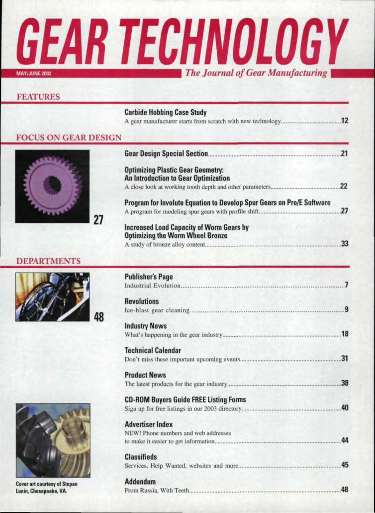
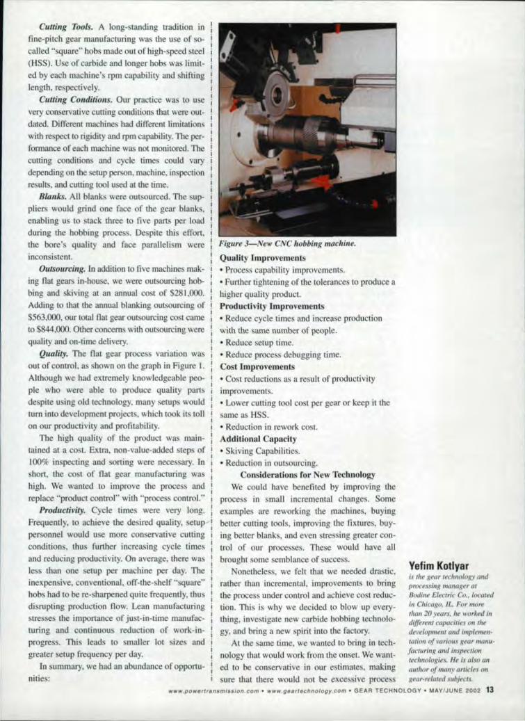
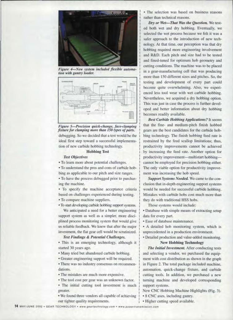
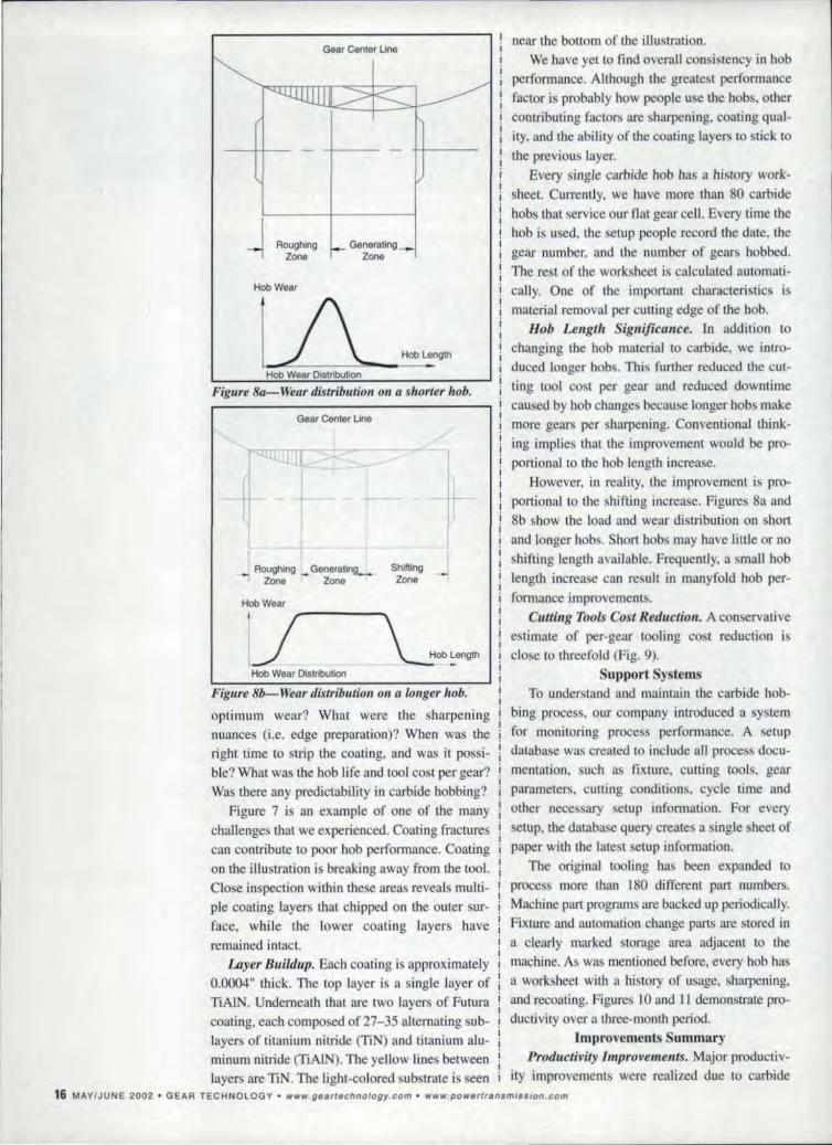
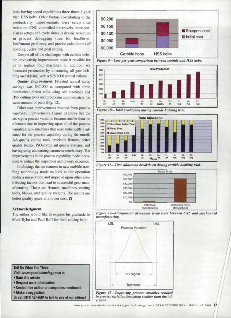
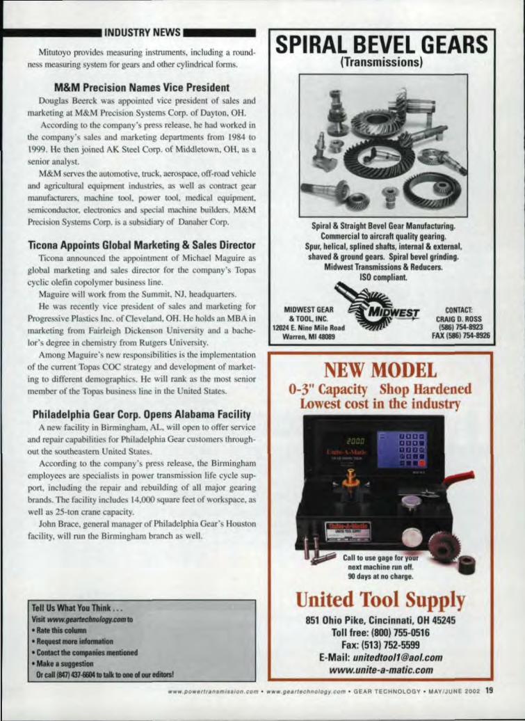
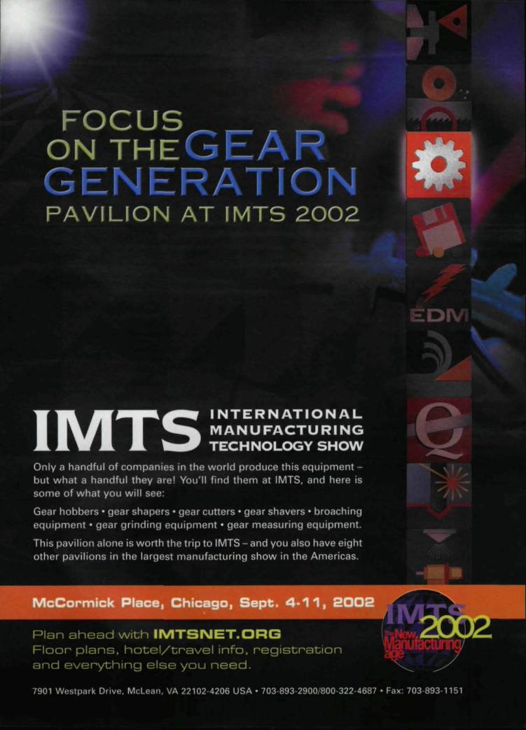
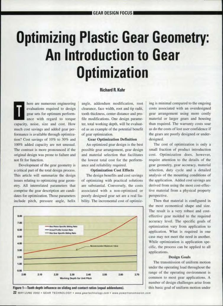
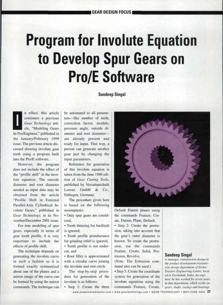
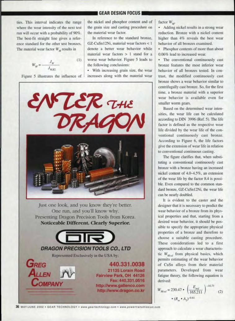
SERVICE
v~BEVEL GEARSSpiral Bevel Gears - Straight Bevel gearsCustom Gea~ - 1 off or QuantityPrototypes amp Re-englneering our speciJllity ~Special Dlvlslon for Fine Pilch bevels i
Gleasoll nol02 Hypold amp Gleason no2A
Contact Gears amp TransmissionsNon Bangalore CooperativeIndl Estate Old Madras RoadBangalore - 560 016
Phone (080) 8410239 Fax (080) 8410185(080) 5282387
Website wwwjamalgearscomEmailjamalgrpbgl vsnlnetill
Rep Offices in Canada - Australia
I Weare the source fO qualitygears F~omdesign to
manufacture bull to deliverycount on
Okamoto Machineryfor your demanding precision
gear and related powertransmission products
Look to us for the finestPreeislon Gears bullbullbull
+ Spiral Bevel + Worm+ Spur amp Helical + Splines
Custom design serviceHigh productlof cipablity
Unmatched quality service amp support
Rep Inquiries Invited I
CaUl todayOkamoto Machinery
847520middot7700 ext 625wwwokamoto bullkmiddotouklcoJp
GEAR INSPECTIONbull Helicalspurworm wheelsbull 24 hr turnaround
HobShaper CutterSharpening Service
bull Up to 10 dta x U lengthbull Rapid turnaround
Calibration of yourGear Inspection System
BCURNampKDCHPh (815)965-4013Fax (815)965middot00]9
1
2500 KisbwaUkee StRockford ~L61104
Ph (937)859middot8503Fax (937)865middot0656351 Fame RoadDayton OH 45449
46 MAYJUNE 2002 bull GEAR TECHNOLOGYmiddot HlHIwgeartechnologycQm wwwpowerransmissioncom
GEAR TOOTHGRIINiDINGi SERVICESSpur - Helical - Double Helical
Capacity up to 605 00 1 DP 29Stroke All ground gears certitied up toAGMA Class 14+ on Zeiss-Htifler1602GMM Inventory of grinders includesHofler 800 Hofler 1253 Supra Hofler 1500two Hofler Nova GNG lnOOs (Fully CNCwith on-board CMM checker) andHofler Rapid 1000 Form Grinder
iKreiter Geartech2530 Garrow St Houston TX 71003Phone 713-237-9793 Fax 713-237-1209Contact Mr Willie WhittingtonVisit OUt Website atwwwkreiter-geartechcom
IHOB SHIARPENIINGSERVIICIE
Star Cuffer Co
West Branch IndustriesSubsidiary of Star Cutter Co
2083 W M-55 West Branch MI 486611-88S-ResharpI-888-737-4277
Phone (9891345-2865 bull FAX (989)345-56601
Induction HardeningSpecialists in Tooth by Tooth -Contour Hardening of ilntentalSpurhelical and bevel gearsOur gear hardening equipmentincludes 5 NATCQ submergedprocess machines and 5 AJAXCNC-controUed gear scanningmachines Tooth by tooth gearhardening from 5DP-l0DP up to1i5tons 200 diameter
American Metal Treating CompanyCleveland Ohio -
Phone (2161 431middot4492middot Fax (216) 431-1508Web wwwamericanmetaitreatingcom
Emiddotmail markamericanmetaltreatingcom
Breakdown Service Available
GEAR TOOTH GRINDlNGSpur bull Helicall
bull Herringbone Iwith groove ICapacity up to 63 OlD
1 IOP 16 face
AGMA Certification InspectionDelivery to Meet Your Requirements
Midwest Gear Corp2182 E Aurora IRdl
Twinsburg OH 44081Phone 330middot425middot4419Fax 330-425-8600
Direct your inquiries 10Ron Humphrey General Manager
ronhmwgearcom
CUSTOM ENGINEERED ampMANUFACTURED CUTTING TOOLS
ESTABLlSHED 1960
FORM REUEVED amp PROFILE GROUNDMILUNG CunERS
GEAR SHAPER ISHAVING CUTlERSALL CLASSES OF HOBS
HSSSaUD CARBIDE amp CARBIDE TIPPED
WHETHER YOU NEED NEW TOOLSMODIFICATIONS RESHARPENINGREPAIRS OR MampM INSPECTIONS
CONTACT US FOR A QUOTE TODAYI
wwwnters bull1ttoolcorcomTel 216middot671middot1017middot Fax 216-871-5431
bull BROACH SHARPENING
HOB SHARPENING
SHAVING CUTTER GRINDING
bull THIN FILM COATING
CUSTOM HEAT TREAT SERVICE
PICK UP AND DELIVERY IN MANY AREAS
I Gleason CUtting ToolsCORPORATION
1351 Windsor RoadLoves Park ill 61111 USA
Phone 815middotB77-8900Fax 61 5-877 -0264
Website wwwmiddotgleasoilcomE-Mailgctcgleasoncom
SERVICE
HOB SiHARPIENllNG(7163) 425-15247 THIN FILM COATINGS
HSS amp Garbide up to 5 DiaStraight Gash
Sharpened amp IinspectedPer AGMA STANDARDS
Quid Tumsround
KORD SHARPENING S~ERVmE9530 - 85TH AVENUE NOMAPLE GROVE MN 553691
HOB SHARPENIING State-nt-tha-art eNC sharpening
and inspection machines
I Wet grindiing with free-cutting CBN ordiamond wheels for Burn freemiddot sharp-ening of carbide or high speed steel
I- Optional recaating and stripping
II I Rush service available
Koepfer America ILLC635 Schneider DriveSouth Elgin Il60177Phone 847-931-41211Fax 847-931middot41~e I
leskoepleramencacom I
tlELP WANTED
IMidwest progressivel gear man-IUfacturer withsfale-ofmiddotthe-ar1facillity is seekingthe foUowing
GEAR IGRINIDING TEICHNICilANRequires J vears experience in setup III oper-atinn of modem eNC geargrinding machinesCN~ gear analytical inspection Bxperience 1
desirable
GEAR HOIBBINGTECHNICIANFlequirBs 3 years experience in setup ampoperation of fine- and medium-pitchmodern CNC gear hobbing machinery I
eNC gear analytica1 inspection experi-ence desirable
LITERATURE
We oHeran attractive benefits packagethat includes medical dental life insur-ance vacation paid holidays and profitsharing Please send resumeto
I
I
Fores1 City IGear
I
PO Box 80Roscoe Il61013middotQ080Phone (815623-2168Toll Free (86S) 623middot2168Fax 1815)623-6620E-mail mwoodfcgearcom
DID YOU FILL OUT THIEFORMS ON PAGES 48-43 IFOR YOUR FREE BUYERS I
GUIDE lISTINGS
OFGEAR TECHNOLOGY
MAGAZINEPAT FLAM
SHOW US YOUR STUFFDo you have a gear-related image that would make a great cover for Gear Technology
GEAR TECHNOLOGV
CALLJEAN BARTZ
AT847-437-6604
pOwltflsmlssloncommiddot gurlchnologycom bull GEAIFI TECHNOLOGYmiddot MIAYIJUNE 2002 4J
ADDENDUM _
FROM RUSSIA WITH TEETH
course The bicycles shell bad a naIT)W I supporting the steering wheel Standardslot for its steering wheel so it needed bicycle parts like brakes and brake
01n a little-knownincident SovietI machinists at Mill Helicopter
I worked in 1988 and 1989 on a special project to be used against
AmericansTiley were given the work by a gear
engineer Boris Zakoldaev who nowuses a different name
Working at Mils Panki factory themachinists made only the metal pansThe composite pieces were made 25miles away in Moscow
The completed machine was latertransported by air into Americas heart-land arriving at Chicagos OHareInternational Airport The machine wastaken to Milwaukee WI and unleashedagainst Americans-at a competitionfor human powered vehicle
The machine was a reclining bicyclewith an egg-shaped shell
Human powered vehicles includebicycles and other vehicles-trikesrickshaws pedal boats-that are pow-ered by people not motors or engines
The attempt was to beat theAmericans says Zakoldaev nowStepan Lunin a transmission engineerwho works in Chesapeake VA forVolvo Penta of the Americas Inc
Lunins bicycle didnt win its raceRidden by another Soviet man the
bicycle wasnt suited for the race
race courses with very gradual or nocurves The race cour e had sharpercurves than the bicycle could easilymanage Also the bicycle was pushedaround by the wind
The bicycle was de igned with anegg-shaped shell to decrease its aerody-namic resistance It wa made a areclining bicycle to reduce the shellsfront area further decreasing its aero-dynamic resistance
But the bicycle wasnt in the sheH-it was the shell The wheels and large
sprocket were mounted on the compos-ite shell with no conventional bicycleframe
Lunin recalls the shells drawbackslittle space danger and no cup holders
His bicycle was the product ofSoviet generosity Lunin explains thatthe Soviet Union was very enthusiasticabout building high-speed bicycles 15years ago So he gOImoney for hisbicycle and three others through grantsfrom three private businesses involvedin developing new ideas in sports
He recalls receiving a budget ofabout 350000 rubles At an exchangerate of 60 cents a ruble the sumamounted 10 about $210000 He nexthired a manufacturer to make the bicy-cles main metal pans
I went to my own company hesay and they did the job for me
The major plastic parts-tile shellpieces-were manufactured at a loca-tion in Moscow Lunins garage
~had experience with the compos-ites he says so Idid that myself
Lunin made four molds for creatingcomplete shells He then combined the
plastic parts with the metal parts thesprocket set the large sprockets bear-ings two aluminum beams (one forholding the large sprocket the other forholding the first beam) and a fork for
Stepan Iunin rides nne 01 his lour speciallymiddotmadsbicycles Aeroflot B iRussiBn Birline was a sponsorproviding lunin will Iree flighlS and cargOI delivolfY otbls bicycles for inlemtJonl fates
lEach of Lunins bicycles had a 21 diameter1l1oothsprocikel will involule leeth and round roots Thelarge sprocket combined will a 13middotloolh sprocket 10create a speed increaser with a 101 ratio
of the Soviet Union an official govern-ment committee
Ioday Lunins too busy for bicy-cling Among other things hes build-ing his own house in Chesapeake VA
Regarding his name Lunin explainsthat Boris Zakoldaev was probably list-ed with the KGB because of his work atMil So he used his dead materna]grandfathers name to more easilyobtain a travel visa Beeomiag a perma-nent US resident he Americanizedthat name slightly to Stepan Lunin
As for his bicycles he recalls thatone is iii a showroom of FlevobikeTechnology in Holland Another is inthe Washington DCarea The othertwo bicycles disappeared from aMoscow warehouse along with part ofthe grant money 0
Tell Us What You Think Visit wwwgeartBchnoJogycomtobull Rate this amelebull Request more infonnationbull Contact the person mentionedbull Make a suggestionOr call (111) Cf1aD1111 1I1k III one of 011 ediIOrs
levers were also addedEach bicycle weighed about 77
pounds Each large sprocket weighed alittle more than 2 pounds=-vdeflnirelyheavy for a bicycle Lunin says
Despite the bicycles weight Luninreached a speed of 806 miles per houron it in the summer of 1988 inMoscow He held that peed for about 7seconds setting a 200-meter speedrecord in the Soviet Union
Lunins peed and time that daywere recorded by the Sport Committee
48 MAYJUNE 2002 bull GEAR TECHNOLOGY wwwgearlechnotogycom wwwsowertrensmisstoncom
Samputensili presents tile new modularS-series in a complete diameter rangefrom 1100up to 3000 mm built inChemnitzlGermany the cradle of gearhobbing
In addition we provide an unmatchedservice and sales network throughoutthe IJS by Meritage Nationai Servicesand its affiliates
SU America Inc8775 Capital AveOak lParlk MI48237lell +1248548middot7177Fax +1 248 548middot4443E-mail salessllamericacomhttpwwwsamputensilicomWith this recent addiJion to our machine
tool line we are able to offer you completesolutions for your gear cutting needs fromroughing to finishing
Contact us todayto find out what we can do for you
QScer1tfied
Hobbing - Profile Grinding - Generating Grinding - Shave Grinding - Chamfering - Oeburring - Shaving Cutter Grinding
Bevel Gear Cutting - Tool and Commodity Management Services (CMS)