mbb pocket 2010 umschlag e layout 1 -...
TRANSCRIPT

PRODUCT RANGE

3
Contents
Benefits and features 4-23500 minifix 24/25500 / 750 K 1T L/R 26/271000 ATHLET quattro 1/2T L/R 28/291000 K 1/2T L/R 30/31500 / 750 M 32/331000 ATHLET quattro 34/351000 E 36/371000 K 38/391500 KL 40/411500 K 42/432000 KL 44/452000 K 46/472500 KL 48/491500 / 2000 KK 50/511500 / 2000 KS 52/532500 KK 54/552500 / 3000 K 56/571500 TwinFold 58/591000 / 1500 KF / KFN 60/611000 KUZ 62/631500 KLUZ 64/651500 KUZ 66/672000 KLUZ 68/692000 KUZ 70/712500 KLUZ 72/732500 / 3000 KUZ 74/751500 / 2000 TrailGate 76/771500 / 2000 TruckGate 78/791500 / 2000 KUZK 80/81750 / 1000 KUZFM 82/831500 / 2000 KUZFM 84/851500 / 2000 KUZF 86/87Column lifts 88/89RATCLIFF PALFINGER 90-93MEDILIFT 94/95MEDIRAMPE 96/97TRAINLIFT 98/99Technical appendix 100-112

4
Reknown for qualityand innovation
As market leader, we continually introduce new innovative
models and update existing products to ensure the safe trans-
portation and delivery of goods.

5
Manufactured in-house
The hydraulic cylinder is one of the most important parts of a taillift. That’s why we only trust one supplier - ourselves! We ma-nufacture around 65,000 cylinders per annum to meet demand.

6
Power opening and power closure using dual-acting hydraulic
cylinders. Therefore not relying on spring force or gravity alone –
so the platform opens and shuts easily even on the steepest of in-
clines.
Powerful, reliable ...

7
Every cylinder is fitted with flow control valves which safely
control the descent of a fully loaded platform, even in the event
of a burst hose in the hydraulic circuit.
... and safe!

8
Our chromium-free pivot pins are solid and not weakened by
lubrication holes. 12 grease nipples for the bearings are located
on the exterior of the cylinder ends to ensure direct delivery of
grease to the bearings.
A good greasing ...

9
A series of lubrication holes evenly distributed guarantee an equal
application of grease.
... for smooth operation!

10
The power pack is housed in the main beam, out of harms way,
and is easily pulled out for inspection and maintenance. In addi-
tion, noise from the hydraulic pump is greatly reduced when the
lift is being used in residential areas or at night.
Easy to maintain

11
Our ‘Intelligent’ foot controls are able to distinguish between con-
tact with the operator’s foot and the load! Should goods be rest-
ing on the foot controls the lift remains static.
‘Intelligent’ foot controls

12
Controls for all applications
We offer a range of tail lift controls to suit your individual require-
ments. We’ve two-handed external controls, internally mounted
controls, wanderlead controls, platform-mounted foot controls
and wireless remote controls.
24-hour operation
The ergonomic control box has translucent instructions lit by an
interior light making it possible to operate the lift safely 24/7 –
even in the dark!

13
K-plus: Speedy diagnosticfault finding
Different control systems for different applications • K-plus Fully electronic with sensor control with electronic memory functions• K1-plus Electronic sensor control
In the event of a lift or component failure, the diagnostic softwarefeatured in K-plus and K1-plus, enables the service engineer to rapidly identify the problem reducing lift downtime and repaircosts.
14
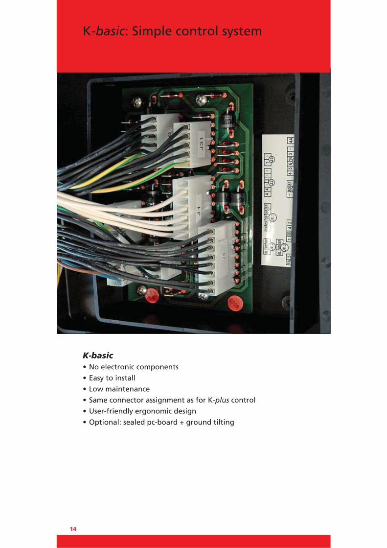
K-basic• No electronic components
• Easy to install
• Low maintenance
• Same connector assignment as for K-plus control
• User-friendly ergonomic design
• Optional: sealed pc-board + ground tilting
K-basic: Simple control system

15
Using the latest LED technology (EN 1756-1) our platform-mounted flashing warning lights operate when the lift is beingused, ensuring the lift is fully visible at all times from the rear andfrom the side, providing additional safety.
For your safety: LED warning lights

16
Restart battery protectorsprevent battery failures
Smart restart battery protectors help save money!Restart battery protectors are useful accessories enhancing the de-
livery program of MBB PALFINGER tail lifts. The patented system
can be retrofitted at any time and easily connects to the control
board. Fitting a restart protector in the power pack avoids a flat
battery due to heavy use of the tail lift. The system cuts out early
enough to ensure that there is sufficient power remaining to re-
start the engine and then recharge the battery. You can resume
your journey without anybody’s help, without spare batteries and
– what is more – without additional costs.
Your advantages• Audible warning protects against flat battery
• Reduced life cycle costs due to low battery wear
• For K-plus, K1-plus and K-basic controls
• Can be retrofitted at any time
• Available for 12 V and 24 V systems

17
AluStar AluKolas
AluLite AluTop
Safe platform surfaces
AluStar – the most versatile platform The clever design of the AluStar treadplate surface assists in preventing slipping in all directions.
AluKolas – latest platform technologyAluKolas is market leader in the innovative production of an aluminium platform. Using a unique hybrid plasma welding process, the sections are neatly welded with minimum heat to attain exceptional robustness without warping the platform (topright picture).
AluLiteAluLite is the perfect platform for 750 M / 1000 AQ / 1000 K and 1500 KL tail lifts. With its longitudinal profiles it ensures high stabilityand low weight. Additionally, it is provided with a well-proven headsection connection. The optional platform roll stops are identical* tothose of AluStar/AluKolas platforms. On request, the platform is avail-able with a transversely milled anti-slip surface (see picture). * not for version 750
AluTopAluTop is the heavy-duty platform fitted to 1500 K to 3000 K tail lifts. 2 tunnels on its back ensure maximum stability. Due to its transverseprofiles the platform surface is exceptionally slip-resistant.

18
AluStar is the most versatile aluminium platform on the market.Since it is not of modular build we can meet customer require-ments by cutting the platform to the required width and depthto suit individual applications. Side ramps can also be added if required.
AluStar – a well-proven classic

19
Keeping your load safe
Our platform roll stops are simple to operate, robust and reliable,protecting your load whilst travelling on the platform. And what’smore - they can be retrofitted! (except for AluLite 750 kg)

20
The optional synthetic coating applied to all our platforms is un-paralleled! The multi-step process thoroughly prepares the platform to bondto the rubberised coating which cushions noise made during theloading and unloading operations, as well as providing an excellent anti-slip surface for improved operator safety.
Reducing the noise emission is especially important when loading
and unloading goods at night in residential areas. Many MBB
PALFINGER tail lifts already comply with the strict noise standard
specified in the Dutch “PIEK“ norm.
Improved safety – reduced noise

21
Nobody wants a product prone to rust and corrosion – and neitherdo we! That’s why we coat our steel platforms with KTL protec-tion as standard. The protective layer minimises the consequencesof stone chip damage and prevents spreading rust. Our KTLcoating has been subjected to a Salt-spray test:
1000 hours in compliance with EN ISO 12 944-2 CSM
With choice of finishesChoose from a robust steel treadplate platform with raised ’studs’that reduce the risk of slipping or a smooth steel surface finishedwith a synthetic anti-slip coating.
Robust, KTL protected steel platforms

22
KTL protectedprevents rust and corrosion
Our lifting mechanisms are also protected with KTL layer as
standard. This minimises the consequences of stone chip damage
and prevents spreading rust. The KTL coating has been subjected
to a Salt-spray test:
1000 hours in compliance with EN ISO 12 944-2 CSM

23
Powder coating forharsh working conditions
In addition to the high-quality KTL protection, customers may also
choose to have the lift polyester powder coated – layer thickness of
at least 100 μm. (RAL colours available). The powder coating is
approved for usage in the food distribution process. It has also
undergone a Salt-spray test.
1400 hours in compliance with EN ISO 12 944-2 CSM

24
500 minifix
Diagram
a (mm) Q (kg)
600 500
700 430
820 360
1120 260
The 500 minifix has been specifically designed for factory built panel
vans and fits virtually all models. It is probably the lightest model on
the market weighing only 156 kg yet lifting a full 500 kg. The lift
features one open and close tilting cylinder. This special arrangement
of the cylinders permits a very shallow installation. Delivered pre-wired
with individual van-specific mounting brackets to permit easy fitting,
without any body modifications required. The lifting device is
prepared in factory for optional assembly of a removable ball-head
coupling. An 800 mm half-width platform is also available, giving free
access to the rear door.

25
The perfect solution for vans
Dimensions 500 minifix
Lift arms (in mm) 500
H (max.) Loading height unloaded 780
H (min.) Loading height loaded 450
F (max.) Middle of main beam to upper edge of loading floor 340
K (min.) At dimension F (max.) 546
D (min.) Installation space (min.) 729
F (min.) -
K (max.) At dimension F (min.) -
D (max.) Installation space (max.) -
Dim
. F
Dim
ensi
on
H(lo
aded
/unl
.)
Dim. KD
im. G
(load
ed/u
nl.)
This tail lift will fit on the following vans• Citroen Jumper (Relay) • Fiat Ducato • Ford Transit • Iveco Daily• Mercedes-Benz Sprinter 3/5• Nissan Interstar & Primastar
• Opel Movano & Vivaro • Peugeot Boxer • Renault Master & Trafic • Volkswagen Crafter 30/35/50 • further vehicle types on request
The specified weights apply to the lightest platforms of the corresponding height. You will find an overview of weights, lift arm lengths and general technical informationin the “Technical Appendix” starting on page 100. Subject to technical changes. Dimensions may vary.
WeightsPlatform type Alum.
Platform width (mm) 1400
Platform height (mm)
1575 154 kg
Technical dataLifting capacity 500 kg
Main beam 110 x 110 mm
Lifting gear hydraulics 1 x lift cylinder / 1 x tilt cylinder
Platform overlap with floor -
Lift arm pitch 600 mm
Load centre - lengthwise 600 mm
Load centre - across center 50 % of the full load on one side
Inclination angle of the platform +90° to -10°

26
500 / 750 K 1T L/R
Tailor-made platform widths to suit individual body specifications,
where access to the rear of the vehicle is required without lower-
ing the tail lift platform. Particularly ideal for refigerated vehicles
allowing clear entry through one door which may be fitted
centrally or to the near or offside.
The platform may be made wider with a foldout lengthways
extension if required, thus giving maximum platform width whilst
retaining minimum stowage area.
a (mm) Q (kg)
600 500
700 430
820 360
1120 260
a (mm) Q (kg)
600 750
700 650
820 550
1120 400
500 K 1T L/R 750 K 1T L/R
Diagram

27
The specified weights apply to the lightest platforms of the corresponding height. You will find an overview of weights, lift arm lengths and general technical informationin the “Technical Appendix” starting on page 100. Subject to technical changes. Dimensions may vary.
Partial width platforms forspecial applications
WeightsPlatform type Alum.
Platform width (mm) 1000
Platform height (mm)
1450 202 kg
1550 204 kg
1600 205 kg
1825 209 kg
Dimensions
Technical data
500 / 750 K 1T L/R
Lift arms (in mm) 600 700
H (max.) Loading height unloaded 1120 1263
H (min.) Loading height loaded 710 759
F (max.) Middle of main beam to upper edge of loading floor 620 703
K (min.) At dimension F (max.) 417 473
D (min.) Installation space (min.) 532 588
F (min.) 380 429
K (max.) At dimension F (min.) 623 711
D (max.) Installation space (max.) 738 826
500 K 1T L/R 750 K 1T L/R
Lifting capacity 500 kg 750 kg
Main beam 110 x 110 mm 110 x 110 mm
Lifting gear hydraulics 2 x lift cylinder / 2 x tilt cylinder
Platform overlap with floor - 44 mm - 44 mm
Lift arm pitch 410 mm 410 mm
Load centre - lengthwise 600 mm 600 mm
Load centre - across center 50 % of the full load on one side
Inclination angle of the platform +90° to -10° +90° to -10°
Dim
ensi
on
H(lo
aded
/unl
.)
Dim
. FDim. K
Dim. DD
im. G
(load
ed/u
nl.)

28
1000 ATHLET quattro 1/2T L/R
These tail lifts, based on the well-proven AQ series, are suitable
for a wide range of applications and are especially suited for fresh
or chilled goods. The platform (available 1/3 or 2/3 widths) need
not be lowered to access the rear door and may be mounted to
the left (AQ1TL) or right (AQ1TR) side of the vehicle. Platform
widths from 800 mm to 1960 mm.
Diagram
a (mm) Q (kg)
600 1000
750 800
950 600
1400 400

29
The specified weights apply to the lightest platforms of the corresponding height. You will find an overview of weights, lift arm lengths and general technical informationin the “Technical Appendix” starting on page 100. Subject to technical changes. Dimensions may vary.
Partial width – full performance
WeightsPlatform type Alum.
Platform width (mm) 1700
Platform height (mm)
1450 259 kg
1550 263 kg
1600 267 kg
1825 271 kg
Dimensions
Technical data
1000 AQ 1/2T L/R
Lift arms (in mm) 700
H (max.) Loading height unloaded 1210
H (min.) Loading height loaded 830
F (max.) Middle of main beam to upper edge of loading floor 650
K (min.) At dimension F (max.) 592
D (min.) Installation space (min.) 742
F (min.) 500
K (max.) At dimension F (min.) 721
D (max.) Installation space (max.) 871
1000 AQ 1T L/R 1000 AQ 2T L/R
Lifting capacity 1000 kg 1000 kg
Main beam 180 x 180 mm 180 x 180 mm
Lifting gear hydraulics 2 x lift cylinder / 2 x tilt cylinder
Platform overlap with floor - 44 mm - 44 mm
Lift arm pitch 410 mm 970 mm
Load centre - lengthwise 600 mm 600 mm
Load centre - across center 50 % of the full load on one side
Inclination angle of the platform +90° to -10° +90° to -10°
Dim
ensi
on
H(lo
aded
/unl
.)
Dim
. FDim. K
Dim. DD
im. G
(load
ed/u
nl.)
30
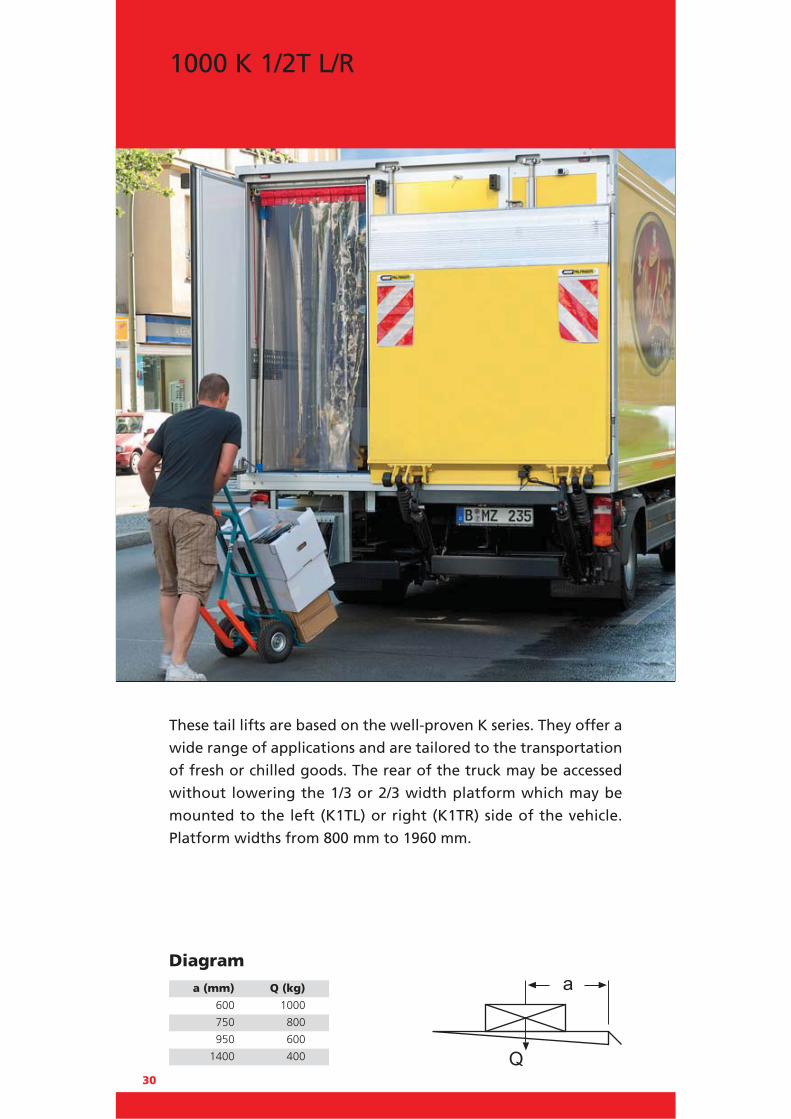
1000 K 1/2T L/R
These tail lifts are based on the well-proven K series. They offer a
wide range of applications and are tailored to the transportation
of fresh or chilled goods. The rear of the truck may be accessed
without lowering the 1/3 or 2/3 width platform which may be
mounted to the left (K1TL) or right (K1TR) side of the vehicle.
Platform widths from 800 mm to 1960 mm.
Diagram
a (mm) Q (kg)
600 1000
750 800
950 600
1400 400
31
The specified weights apply to the lightest platforms of the corresponding height. You will find an overview of weights, lift arm lengths and general technical informationin the “Technical Appendix” starting on page 100. Subject to technical changes. Dimensions may vary.
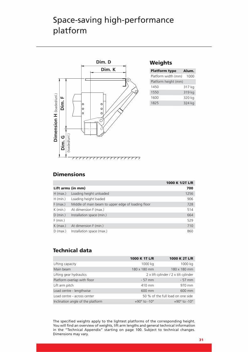
Space-saving high-performance platform
WeightsPlatform type Alum.Platform width (mm) 1000
Platform height (mm)
1450 317 kg
1550 319 kg
1600 320 kg
1825 324 kg
Dimensions
Technical data
1000 K 1/2T L/R
Lift arms (in mm) 700
H (max.) Loading height unloaded 1256
H (min.) Loading height loaded 906
F (max.) Middle of main beam to upper edge of loading floor 728
K (min.) At dimension F (max.) 514
D (min.) Installation space (min.) 664
F (min.) 529
K (max.) At dimension F (min.) 710
D (max.) Installation space (max.) 860
1000 K 1T L/R 1000 K 2T L/R
Lifting capacity 1000 kg 1000 kg
Main beam 180 x 180 mm 180 x 180 mm
Lifting gear hydraulics 2 x lift cylinder / 2 x tilt cylinder
Platform overlap with floor - 57 mm - 57 mm
Lift arm pitch 410 mm 970 mm
Load centre - lengthwise 600 mm 600 mm
Load centre - across center 50 % of the full load on one side
Inclination angle of the platform +90° to -10° +90° to -10°
Dim
ensi
on
H(lo
aded
/unl
.)
Dim
. F
Dim. K
Dim. DD
im. G
(load
ed/u
nl.)

32
500 / 750 M
a (mm) Q (kg)
600 500
700 430
820 360
1120 260
500 M 750 M
a (mm) Q (kg)
600 750
700 650
820 550
1120 400
Diagram
The newly developed 500 / 700 M range of lifts is specially designed
for small vehicles up to 7.5 tonnes gvw. The lift features a strong,
lightweight platform and a robust 4-cylinder lift mechanism with
an overall lift weight of only 200 kg (1200 mm platform height). A
choice of models to fit various chassis widths to meet customer
requirements. The standard lift has a single-piece underrun
bumper. Optionally, a three-piece screwable underrun bumper is
available, which can also be supplied with a removable ball-head
coupling. Dedicated mounting brackets enable quick installation
to virtually all U-profile or omega-profile chassis.

33
The specified weights apply to the lightest platforms of the corresponding height. You will find an overview of weights, lift arm lengths and general technical informationin the “Technical Appendix” starting on page 100. Subject to technical changes. Dimensions may vary.
Lightweight four cylinder cantilever
WeightsPlatform type Alum.
Platform width (mm) 2200
Platform height (mm)
1200 200 kg*
1450 209 kg*
1550 213 kg*
Dimensions
Technical data
500 / 750 M
Lift arms (in mm) 550
H (max.) Loading height unloaded 960
H (min.) Loading height loaded 700
F (max.) Middle of main beam to upper edge of loading floor 510
K (min.) At dimension F (max.) 452
D (min.) Installation space (min.) 543
F (min.) 370
K (max.) At dimension F (min.) 555
D (max.) Installation space (max.) 646
500 M 750 M
Lifting capacity 500 kg 750 kg
Main beam 120 x 80 x 5 mm 120 x 80 x 5 mm
Lifting gear hydraulics 2 x lift cylinder / 2 x tilt cylinder
Platform overlap with floor - 44 mm - 44 mm
Lift arm pitch 1240 mm 1240 mm
Load centre - lengthwise 600 mm 600 mm
Load centre - across center 50 % of the full load on one side
Inclination angle of the platform +90° to -10° +90° to -10°
*) 11 kg additional weight with three-part underrunbumper
Dim
ensi
on
H(lo
aded
/unl
.)
Dim
. FDim. K
Dim. DD
im. G
(load
ed/u
nl.)

34
1000 ATHLET quattro
The 1000 ATHLET quattro offers a lightweight cantilever lifting
solution with 2 lift and 2 tilt cylinders for maximum performance.
It features a wide, sturdy aluminium platform up to 2500 mm
wide x 1550 mm or 1825 mm deep – overall weight from 272 kg.
Lift frame is KTL coated to protect against corrosion and has many
beneficial features as standard. Rear closure option offers
additional weight saving. Also available with a steel platform with
optional wide lift arm pitch of 1320 mm.
Diagram
a (mm) Q (kg)
600 1000
750 800
950 600
1400 400

35
The specified weights apply to the lightest platforms of the corresponding height. You will find an overview of weights, lift arm lengths and general technical informationin the “Technical Appendix” starting on page 100. Subject to technical changes. Dimensions may vary.
The dependable, lightweight cantilever with four cylinders
Dim
ensi
on
H(lo
aded
/unl
.)
Dim
. FDim. K
Dim. D WeightsPlatform type Alum.
Platform width (mm) 2400
Platform height (mm)
1550 282 kg
1700 289 kg
1825 295 kg
Platform type Steel
Platform width (mm) 2400
Platform height (mm)
1209 312 kg
1509 357 kg
1809 402 kg
Dim
. G(lo
aded
/unl
.)
Dimensions
Technical data
1000 ATHLET quattro
Lift arms (in mm) 600 700
H (max.) Loading height unloaded 1100 1210
H (min.) Loading height loaded 750 830
F (max.) Middle of main beam to upper edge of loading floor 620 650
K (min.) At dimension F (max.) 467 592
D (min.) Installation space (min.) 617 742
F (min.) 420 500
K (max.) At dimension F (min.) 652 721
D (max.) Installation space (max.) 802 871
1000 ATHLET quattro
Lifting capacity 1000 kg
Main beam 180 x 180 mm
Lifting gear hydraulics 2 x lift cylinder / 2 x tilt cylinder
Platform overlap with floor - 44 mm
Lift arm pitch Lift arm length 600 / 700 mm = 1320 mm / 1100 mm
Load centre - lengthwise 600 mm
Load centre - across center 50 % of the full load on one side
Inclination angle of the platform +90° to -10°

36
1000 E
a (mm) Q (kg) 600 1000
750 800
950 600
1400 400
2400 230
1000 kg capacity cantilever features the new revolutionary e-DRIVE,
which has no hydraulic components and uses innovative electrical
cylinders instead. Its futuristic design concept does away with oil, valve
and hydraulic hose changes. Moreover, the battery recharges whilst the
lift is being operated. Using well proven parallelogram mechanics in
conjunction with the newly designed drive technology provides for
advanced technical features. Although the initial cost of the lift using
this advanced technology is more expensive than standard lifts, break
even point is reached after three years, and the overall running costs
over its entire life are considerably less.
Diagram

37
The specified weights apply to the lightest platforms of the corresponding height. You will find an overview of weights, lift arm lengths and general technical informationin the “Technical Appendix” starting on page 100. Subject to technical changes. Dimensions may vary.
Ecologically friendly
Dim. K WeightsPlatform type Alum.
Platform width (mm) 2500
Platform height (mm)
1550 377 kg
1825 391 kg
Dim
. G(lo
aded
/unl
.)
Dimensions
Technical data
1000 E
Lift arms (in mm) 700
H (max.) Loading height unloaded 1200
H (min.) Loading height loaded 825
F (max.) Middle of main beam to upper edge of loading floor 650
K (min.) At dimension F (max.) 603
D (min.) Installation space (min.) 773
F (min.) 500
K (max.) At dimension F (min.) 716
D (max.) Installation space (max.) 886
1000 E
Lifting capacity 1000 kg
Main beam 180 x 180 mm
Lifting gear drive 1 x electrical lift cylinder / 1 x electrical tilt cylinder
Platform overlap with floor 63 mm
Lift arm pitch 1345 mm
Load centre - lengthwise 600 mm
Inclination angle of the platform +90° to -10°
Dim
ensi
on
H(lo
aded
/unl
.)

38
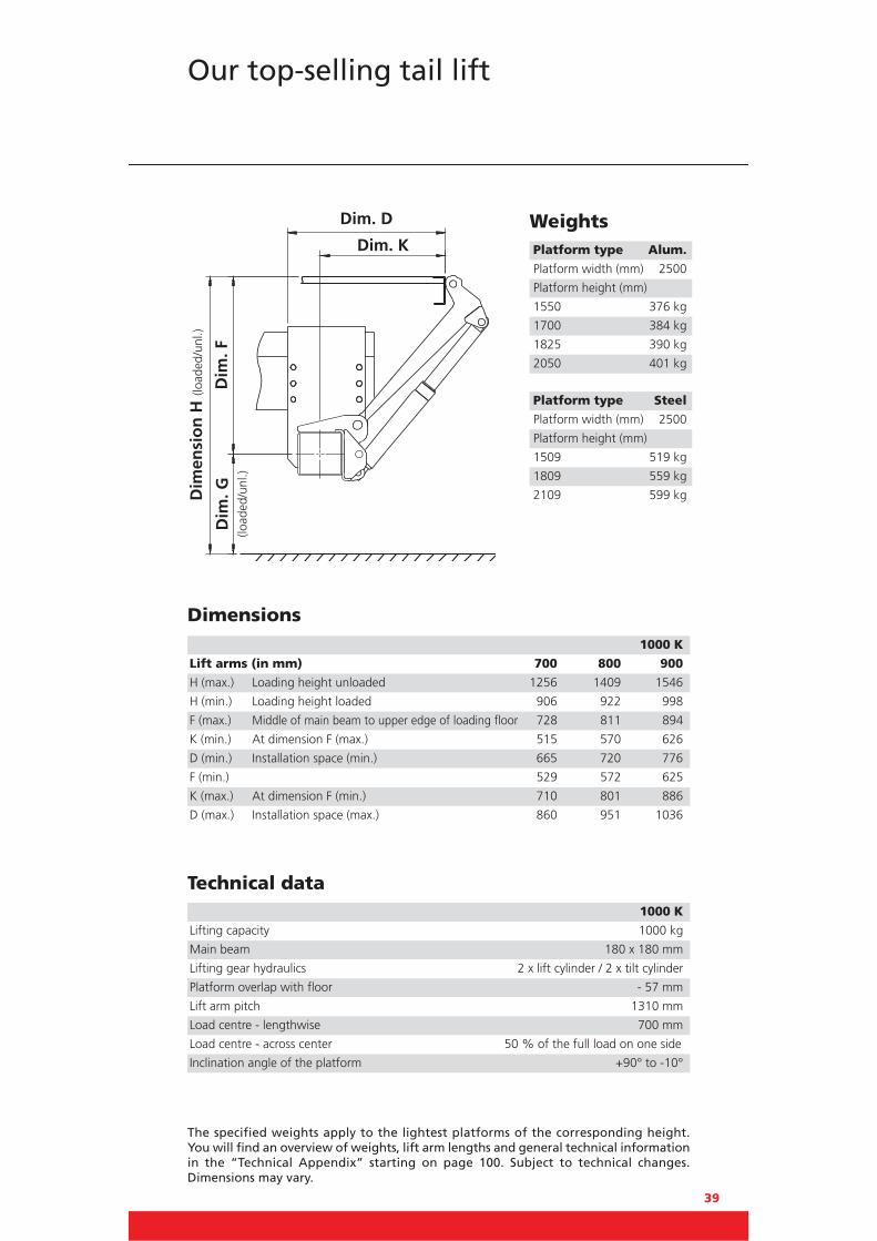
1000 K
The 1000 K is the traditional cantilever with a payload of 1000 kg
(with a 700 mm load centre) designed for heavy duty use. It is
extremely robust and dependable for day-to-day use. In short: its
performance rating couldn’t be better. Available with both steel
and aluminium platforms, it features 4-cylinder technology and is
suitable for a wide range of floor heights and ideal for larger
vehicles.
Diagram
a (mm) Q (kg)
700 1000
875 800
1150 600
1700 400
39
The specified weights apply to the lightest platforms of the corresponding height. You will find an overview of weights, lift arm lengths and general technical informationin the “Technical Appendix” starting on page 100. Subject to technical changes. Dimensions may vary.
Our top-selling tail lift
WeightsPlatform type Alum.
Platform width (mm) 2500
Platform height (mm)
1550 376 kg
1700 384 kg
1825 390 kg
2050 401 kg
Dimensions
Technical data
1000 K
Lift arms (in mm) 700 800 900
H (max.) Loading height unloaded 1256 1409 1546
H (min.) Loading height loaded 906 922 998
F (max.) Middle of main beam to upper edge of loading floor 728 811 894
K (min.) At dimension F (max.) 515 570 626
D (min.) Installation space (min.) 665 720 776
F (min.) 529 572 625
K (max.) At dimension F (min.) 710 801 886
D (max.) Installation space (max.) 860 951 1036
1000 K
Lifting capacity 1000 kg
Main beam 180 x 180 mm
Lifting gear hydraulics 2 x lift cylinder / 2 x tilt cylinder
Platform overlap with floor - 57 mm
Lift arm pitch 1310 mm
Load centre - lengthwise 700 mm
Load centre - across center 50 % of the full load on one side
Inclination angle of the platform +90° to -10°
Platform type Steel
Platform width (mm) 2500
Platform height (mm)
1509 519 kg
1809 559 kg
2109 599 kgDim
ensi
on
H(lo
aded
/unl
.)
Dim
. FDim. K
Dim. DD
im. G
(load
ed/u
nl.)

40
1500 KL
A versatile standard cantilever featuring a lightweight aluminium
platform lifting 1500 kg. Designed to maximise vehicle payload,
it is available in a wide range of platform sizes to suit many
applications. The 4-cylinder lift mechanism provides optimal
performance. Suitable for floor heights up to 1546 mm.
Diagram
a (mm) Q (kg)
600 1500
720 1250
900 1000
1200 750

41
The specified weights apply to the lightest platforms of the corresponding height. You will find an overview of weights, lift arm lengths and general technical informationin the “Technical Appendix” starting on page 100. Subject to technical changes. Dimensions may vary.
Light, strong and efficient
WeightsPlatform type Alum.
Platform width (mm) 2500
Platform height (mm)
1550 390 kg
1700 398 kg
1825 404 kg
1950 410 kg
2050 415 kg
2200 423 kg
Dimensions
Technical data
1500 KL
Lift arms (in mm) 700 800 900
H (max.) Loading height unloaded 1256 1409 1546
H (min.) Loading height loaded 906 922 998
F (max.) Middle of main beam to upper edge of loading floor 728 811 894
K (min.) At dimension F (max.) 515 570 626
D (min.) Installation space (min.) 665 720 776
F (min.) 529 572 625
K (max.) At dimension F (min.) 710 801 886
D (max.) Installation space (max.) 860 951 1036
1500 KL
Lifting capacity 1500 kg
Main beam 180 x 180 mm
Lifting gear hydraulics 2 x lift cylinder / 2 x tilt cylinder
Platform overlap with floor - 57 mm
Lift arm pitch 1310 mm
Load centre - lengthwise 600 mm
Load centre - across center 50 % of the full load on one side
Inclination angle of the platform +90° to -10°
Platform type Steel
Platform width (mm) 2500
Platform height (mm)
1509 528 kg
1809 568 kg
2109 608 kg
Dim
ensi
on
H(lo
aded
/unl
.)
Dim
. FDim. K
Dim. DD
im. G
(load
ed/u
nl.)

42
1500 K
Probably the most reliable, heavy duty lift on the market with a
lifting centre of 1000 mm. Suitable for a wide range of applicati-
ons and fits most vehicle bodies and trailers. The 4-cylinder lift
mechanism is available with 5 different lift arms, ranging from
700 mm to 1100 mm. Both steel and aluminium platforms are
‘made to measure’ available up to a maximum depth of 2800 mm.
Diagram
a (mm) Q (kg)
1000 1500
1200 1250
1500 1000
1850 800
2400 600

43
The specified weights apply to the lightest platforms of the corresponding height. You will find an overview of weights, lift arm lengths and general technical informationin the “Technical Appendix” starting on page 100. Subject to technical changes. Dimensions may vary.
Robust, dependable and efficient
WeightsPlatform type Alum.
Platform width (mm) 2500
Platform height (mm)
1700 516 kg
1825 524 kg
2050 539 kg
2200 548 kg
2300 555 kg
2400 565 kg
2650 581 kg
Dimensions
Technical data
1500 K
Lift arms (in mm) 700 800 900 1000 1100
H (max.) Loading height unloaded 1200 1428 1548 1651 1793
H (min.) Loading height loaded 883 941 1006 950 1023
F (max.) Middle of main beam to upper edge of loading floor 650 817 924 977 1056
K (min.) At dimension F (max.) 618 601 623 722 783
D (min.) Installation space (min.) 768 751 773 872 933
F (min.) 508 566 614 569 608
K (max.) At dimension F (min.) 726 820 907 1041 1132
D (max.) Installation space (max.) 876 970 1057 1191 1282
1500 K
Lifting capacity 1500 kg
Main beam 180 x 180 mm
Lifting gear hydraulics 2 x lift cylinder / 2 x tilt cylinder
Platform overlap with floor - 63 mm
Lift arm pitch 1300 mm
Load centre - lengthwise 1000 mm
Load centre - across center 50 % of the full load on one side
Inclination angle of the platform +90° to -10°
Platform type Steel
Platform width (mm) 2500
Platform height (mm)
1509 620 kg
1809 660 kg
2109 700 kg
Dim
ensi
on
H(lo
aded
/unl
.)
Dim
. FDim. K
Dim. DD
im. G
(load
ed/u
nl.)

44
2000 KL
2000 KL is a powerful tail lift for demanding applications that
require a lifting capacity of 2000 kg with a load clearance of
750 mm. 5 different lift arms and models with aluminium or steel
platforms are available. A wide range of options are available, to
meet the requirements of virtually all applications.
Diagram
a (mm) Q (kg)
750 2000
900 1650
1100 1300
1600 950
2400 600

45
The specified weights apply to the lightest platforms of the corresponding height. You will find an overview of weights, lift arm lengths and general technical informationin the “Technical Appendix” starting on page 100. Subject to technical changes. Dimensions may vary.
2000 kg lifting capacity, just in case
WeightsPlatform type Alum.
Platform width (mm) 2500Platform height (mm) 1550 507 kg1700 516 kg1825 524 kg1950 532 kg2050 539 kg2200 548 kg2300 555 kg2400 565 kg2650 581 kg
Dimensions
Technical data
2000 KL
Lift arms (in mm) 700 800 900 1000 1100
H (max.) Loading height unloaded 1200 1428 1548 1651 1793
H (min.) Loading height loaded 883 1011 1006 950 1023
F (max.) Middle of main beam to upper edge of loading floor 650 817 924 977 1056
K (min.) At dimension F (max.) 618 601 623 722 783
D (min.) Installation space (min.) 768 751 773 872 933
F (min.) 508 566 614 569 608
K (max.) At dimension F (min.) 726 820 907 1041 1132
D (max.) Installation space (max.) 876 970 1057 1191 1282
2000 KL
Lifting capacity 2000 kg
Main beam 180 x 180 mm
Lifting gear hydraulics 2 x lift cylinder / 2 x tilt cylinder
Platform overlap with floor - 63 mm
Lift arm pitch 1300 mm
Load centre - lengthwise 750 mm
Load centre - across center 50 % of the full load on one side
Inclination angle of the platform +90° to -10°
Platform type Steel
Platform width (mm) 2500Platform height (mm) 1509 623 kg1809 663 kg2109 703 kg2409 743 kg
Dim
ensi
on
H(lo
aded
/unl
.)
Dim
. FDim. K
Dim. DD
im. G
(load
ed/u
nl.)

46
2000 K
Lifting a full 2000 kg, the 2000 K offers a choice of steel or
aluminium platforms, up to a maximum depth of 2800 mm and is
frequently chosen for use by the food and drink distribution
industry. The 4-cylinder lift mechanism is available with four
different lift arms, ranging from 700 mm to 1100 mm.
a (mm) Q (kg) 1000 2000
1250 1600
1600 1250
1900 1050
2200 910
Diagram

47
The specified weights apply to the lightest platforms of the corresponding height. You will find an overview of weights, lift arm lengths and general technical informationin the “Technical Appendix” starting on page 100. Subject to technical changes. Dimensions may vary.
Ideal for heavier loads
WeightsPlatform type Alum.
Platform width (mm) 2500
Platform height (mm) 1550 511 kg1700 520 kg1825 528 kg1950 536 kg2050 543 kg2200 552 kg2300 559 kg2400 569 kg2650 585 kg
Dimensions
Technical data
2000 K
Lift arms (in mm) 700 800 900 1000
H (max.) Loading height unloaded 1160 1345 1444 1651
H (min.) Loading height loaded 883 941 1006 950
F (max.) Middle of main beam to upper edge of loading floor 650 785 820 977
K (min.) At dimension F (max.) 618 641 751 722
D (min.) Installation space (min.) 768 791 901 872
F (min.) 508 566 614 569
K (max.) At dimension F (min.) 726 820 907 1041
D (max.) Installation space (max.) 876 970 1057 1191
2000 K
Lifting capacity 2000 kg
Main beam 180 x 180 mm
Lifting gear hydraulics 2 x lift cylinder / 2 x tilt cylinder
Platform overlap with floor - 63 mm
Lift arm pitch 1300 mm
Load centre - lengthwise 1000 mm
Load centre - across center 50 % of the full load on one side
Inclination angle of the platform +90° to -10°
Platform type Steel
Platform width (mm) 2500
Platform height (mm) 1509 625 kg1809 665 kg2109 705 kg2409 745 kg
Dim
ensi
on
H(lo
aded
/unl
.)
Dim
. FDim. K
Dim. DD
im. G
(load
ed/u
nl.)

48
2500 KL
Diagram
a (mm) Q (kg)
750 2500
900 2050
1100 1700
1600 1150
2400 750
The 2500 KL is the No. 1 Tail Lift for all heavy goods applications.
Lifting a full 2500 kg at a load distance of 750 mm it is available with
both aluminium and steel platforms. A wide range of options, inclu-
ding a choice of 4 different lift arms, makes it suitable for virtually
all heavy load transportation requirements.

49
The specified weights apply to the lightest platforms of the corresponding height. You will find an overview of weights, lift arm lengths and general technical informationin the “Technical Appendix” starting on page 100. Subject to technical changes. Dimensions may vary.
Ideal for heavy loads and high requirements
WeightsPlatform type Alum.
Platform width (mm) 2500
Platform height (mm) 1550 513 kg1700 522 kg1825 530 kg1950 538 kg2050 545 kg2200 554 kg2300 561 kg2400 571 kg2650 587 kg
Dimensions
Technical data
2500 KL
Lift arms (in mm) 700 800 900 1000
H (max.) Loading height unloaded 1160 1345 1444 1651
H (min.) Loading height loaded 883 941 1006 950
F (max.) Middle of main beam to upper edge of loading floor 650 785 820 977
K (min.) At dimension F (max.) 618 641 751 722
D (min.) Installation space (min.) 768 791 901 872
F (min.) 508 566 614 569
K (max.) At dimension F (min.) 726 820 907 1041
D (max.) Installation space (max.) 876 970 1057 1191
2500 KL
Lifting capacity 2500 kg
Main beam 180 x 180 mm
Lifting gear hydraulics 2 x lift cylinder / 2 x tilt cylinder
Platform overlap with floor - 63 mm
Lift arm pitch 1300 mm
Load centre - lengthwise 750 mm
Load centre - across center 50 % of the full load on one side
Inclination angle of the platform +90° to -10°
Platform type Steel
Platform width (mm) 2400Platform height (mm) 1509 630 kg1809 668 kg2109 706 kg2409 749 kg
Dim
ensi
on
H(lo
aded
/unl
.)
Dim
. FDim. K
Dim. DD
im. G
(load
ed/u
nl.)

50
1500 / 2000 KK
a (mm) Q (kg)
1000 1500
1200 1250
1500 1000
1850 800
2400 600
1500 KK 2000 KK
a (mm) Q (kg)
750 2000
900 1650
1100 1300
1600 950
2400 600
Diagram
This special lift is designed for fitting to vehicles with a deep
coupling system. It uses well-proven standard components of
1500 K and 2000 K lifts. The single-piece underrun bumper is
spring-loaded and, on request, hydraulically pivoting. The long
lift arm (1100 mm) permits level mounting of the platform.

51
The specified weights apply to the lightest platforms of the corresponding height. You will find an overview of weights, lift arm lengths and general technical informationin the “Technical Appendix” starting on page 100. Subject to technical changes. Dimensions may vary.
Cuts a long story short
WeightsPlatform type Alum.
Platform width (mm) 2500
Platform height (mm) 1550 671 kg1700 680 kg1825 690 kg1950 696 kg2050 703 kg2200 712 kg2300 719 kg2400 729 kg2650 745 kg
Dimensions
Technical data
1500 / 2000 KK
Lift arms (in mm) 1100
H (max.) Loading height unloaded 1793
H (min.) Loading height loaded 1023
F (max.) Middle of main beam to upper edge of loading floor 1056
K (min.) At dimension F (max.) 783
D (min.) Installation space (min.) 1028
F (min.) 608
K (max.) At dimension F (min.) 1132
D (max.) Installation space (max.) 1377
1500 KK 2000 KK
Lifting capacity 1500 kg 2000 kg
Main beam 180 x 180 mm 180 x 180 mm
Lifting gear hydraulics 2 x lift cylinder / 2 x tilt cylinder
Platform overlap with floor - 63 mm - 63 mm
Lift arm pitch 1300 mm 1300 mm
Load centre - lengthwise 1000 mm 750 mm
Load centre - across center 50 % of the full load on one side
Inclination angle of the platform +90° to -10° +90° to -10°
Platform type Steel
Platform width (mm) 2500
Platform height (mm) 1509 767 kg1809 807 kg2109 847 kg2409 887 kg
Dim
ensi
on
H(lo
aded
/unl
.)
Dim
. FDim. K
Dim. DD
im. G
(load
ed/u
nl.)
52
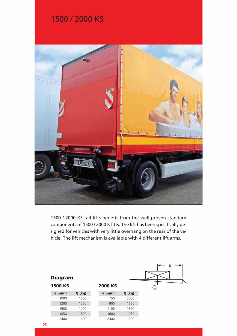
1500 / 2000 KS
a (mm) Q (kg)
1000 1500
1200 1250
1500 1000
1850 800
2400 600
1500 KS 2000 KS
a (mm) Q (kg)
750 2000
900 1650
1100 1300
1600 950
2400 600
Diagram
1500 / 2000 KS tail lifts benefit from the well-proven standard
components of 1500 / 2000 K lifts. The lift has been specifically de-
signed for vehicles with very little overhang on the rear of the ve-
hicle. The lift mechanism is available with 4 different lift arms.

53
The specified weights apply to the lightest platforms of the corresponding height. You will find an overview of weights, lift arm lengths and general technical informationin the “Technical Appendix” starting on page 100. Subject to technical changes. Dimensions may vary.
Short overhang
WeightsPlatform type Alum.
Platform width (mm) 2500
Platform height (mm) 1550 532 kg1700 541 kg1825 549 kg1950 557 kg2050 564 kg2200 572 kg2300 580 kg2400 590 kg2650 606 kg
Dimensions
Technical data
1500 / 2000 KS
Lift arms (in mm) 750 800 850 950
H (max.) Loading height unloaded 1340 1416 1505 1657
H (min.) Loading height loaded 1127 1165 1204 1281
F (max.) Middle of main beam to upper edge of loading floor 858 904 967 1061
K (min.) At dimension F (max.) 413 434 410 444
D (min.) Installation space (min.) 563 584 560 594
F (min.) 742 780 819 896
K (max.) At dimension F (min.) 602 635 666 730
D (max.) Installation space (max.) 752 785 816 880
1500 KS 2000 KS
Lifting capacity 1500 kg 2000 kg
Main beam 180 x 180 mm 180 x 180 mm
Lifting gear hydraulics 2 x lift cylinder / 2 x tilt cylinder
Platform overlap with floor - 63 mm - 63 mm
Lift arm pitch 1300 mm 1300 mm
Load centre - lengthwise 1000 mm 750 mm
Load centre - across center 50 % of the full load on one side
Inclination angle of the platform +90° to -10° +90° to -10°
Platform type Steel
Platform width (mm) 2500
Platform height (mm) 1509 641 kg1809 681 kg2109 721 kg2409 761 kg
Dim
ensi
on
H(lo
aded
/unl
.)
Dim
. FDim. K
Dim. DD
im. G
(load
ed/u
nl.)

54
2500 KK
a (mm) Q (kg) 1000 2500
1200 2050
1500 1650
1800 1350
2100 1150
Special applications require special equipment. With its exceptionally
large load clearance of 1000 mm and its lifting capacity of 2500 kg,
the 2500 KK is rightly considered one of the most powerful tail lifts in
its class. It is designed for a wide range of applications such as food
and beverage distribution, and for drawbar units.
The single-piece underrun bumper is pivoting spring-loaded or
hydraulically operated. The long lift arm (1100 mm) permits level
mounting of the platform.
Diagram

55
The specified weights apply to the lightest platforms of the corresponding height. You will find an overview of weights, lift arm lengths and general technical informationin the “Technical Appendix” starting on page 100. Subject to technical changes. Dimensions may vary.
Ideal for heavy loads
WeightsPlatform type Alum.
Platform width (mm) 2400
Platform height (mm)
2050 809 kg
2200 821 kg
Dimensions
Technical data
2500 KK
Lift arms (in mm) 1100
H (max.) Loading height unloaded 1577
H (min.) Loading height loaded 835
F (max.) Middle of main beam to upper edge of loading floor 840
K (min.) At dimension F (max.) 1010
D (min.) Installation space (min.) 1145
F (min.) 420
K (max.) At dimension F (min.) 1189
D (max.) Installation space (max.) 1324
2500 KK
Lifting capacity 2500 kg
Main beam 180 x 180 mm
Lifting gear hydraulics 2 x lift cylinder / 2 x tilt cylinder
Platform overlap with floor - 72 mm
Lift arm pitch 1300 mm
Load centre - lengthwise 1000 mm
Load centre - across center 50 % of the full load on one side
Inclination angle of the platform +90° to -10°
Platform type Steel
Platform width (mm) 2400
Platform height (mm)
1809 1000 kg
2009 1031 kg
2409 1094 kg
Dim
ensi
on
H(lo
aded
/unl
.)
Dim
. FDim. K
Dim. DD
im. G
(load
ed/u
nl.)

56
2500 / 3000 K
a (mm) Q (kg)
1200 2500
1400 2100
1600 1875
1800 1650
2400 1250
2500 K 3000 K
a (mm) Q (kg)
1000 3000
1200 2500
1500 2000
1800 1650
2400 1250
Diagram
The 2500 / 3000 K lifts have been cleverly designed to provide
exceptionally stable four-cylinder lifts capable of lifting goods up
to 3000 kg, making them ideal for the transportation of motor
vehicles and computerised products. Available with either steel or
aluminium platforms with a load centre of 1000 or 1200 mm.
Optional hydraulic stabiliser jacks provide additional load stability.
A powerful, low-noise power pack in the square main beam
reduces noise during loading or unloading to a minimum.

57
The specified weights apply to the lightest platforms of the corresponding height. You will find an overview of weights, lift arm lengths and general technical informationin the “Technical Appendix” starting on page 100. Subject to technical changes. Dimensions may vary.
The most powerful liftin the range
WeightsPlatform type Alum.
Platform width (mm) 2400
Platform height (mm)
1820 709 kg
2070 721 kg
2200 737 kg
2450 780 kg
Dimensions
Technical data
2500 / 3000 K
Lift arms (in mm) 900 1000
H (max.) Loading height unloaded 1554 1748
H (min.) Loading height loaded 1030 1180
F (max.) Middle of main beam to upper edge of loading floor 924 1027
K (min.) At dimension F (max.) 654 679
D (min.) Installation space (min.) 809 834
F (min.) 645 795
K (max.) At dimension F (min.) 901 922
D (max.) Installation space (max.) 1056 1077
2500 K 3000 K
Lifting capacity 2500 kg 3000 kg
Main beam 180 x 180 mm 180 x 180 mm
Lifting gear hydraulics 2 x lift cylinder / 2 x tilt cylinder
Platform overlap with floor - 72 mm - 72 mm
Lift arm pitch 1300 mm 1300 mm
Load centre - lengthwise 1200 mm 1000 mm
Load centre - across center 50 % of the full load on one side
Inclination angle of the platform +90° to -10° +90° to -10°
Platform type Steel
Platform width (mm) 2400
Platform height (mm)
1809 907 kg
2009 938 kg
2409 1001 kgDim
ensi
on
H(lo
aded
/unl
.)
Dim
. FDim. K
Dim. DD
im. G
(load
ed/u
nl.)

58
1500 TwinFold
a (mm) Q (kg) 600 1500
720 1250
900 1000
1200 750
The TwinFold is a light weight, 2-cylinder tuckunder lift with a lifting
capacity of 1500 kg. Its folding platform stows under the vehicle
chassis, providing clear access to the rear of the vehicle when required.
Platforms available 1200 mm and 1400 mm deep. Designed for dry
freight applications, it is ideal for the lifting of pallets and roll
cages. With its two lift cylinders and two parallel struts, the TwinFold
lift offers full stability. Mechanical auto-tilt at ground level.
Platforms are available as all aluminium or aluminium/steel to suit
individual requirements. The power pack is mounted in the main
beam for low noise and protection against the elements.
Also available without a floor end plate for refrigerated applications
and retrofit.*
*) A 1000 kg capacity model will be available early 2011.
Diagram

59
The specified weights apply to the lightest platforms of the corresponding height. You will find an overview of weights, lift arm lengths and general technical informationin the “Technical Appendix” starting on page 100. Subject to technical changes. Dimensions may vary.
Lightweight and easy to use
Dimensions
Technical data
1000 / 1500 TwinFold
Lift arms (in mm) 900
H (max.) Loading height unloaded 1500
H (min.) Loading height loaded -
F (max.) Middle of main beam to upper edge of loading floor 850
K (min.) At dimension F (max.) 820
D (min.) Installation space (min.) K+340
F (min.) 737
K (max.) At dimension F (min.) 955
G (max.) Unloaded (middle of main beam to ground) 650
G (min.) Loaded 400
E (max.) Vehicle frame width (max.) 870
E (min.) Vehicle frame width (min.) 650
1000 / 1500 TwinFold
Lifting capacity 1500 kg
Main beam 180 x 180 mm
Lifting gear hydraulics 2 x lift cylinder
Lift arm pitch 1310 mm
Load centre - lengthwise 600 mm
Load centre - across center 50 % of the full load on one side
Inclination angle of the platform +8° to -8°
Dim. K
Dim. D WeightsPlatf. type Alum./Alum.
Platform width (mm) 2300
Platform height (mm)
1210 424 kg
1355 442 kg
Platf. type Steel/Alum.
Platform width (mm) 2300
Platform height (mm)
1210 468 kg
1415 491 kg
Dim
ensi
on
H(lo
aded
/unl
.)
Dim
. FD
im. G
(load
ed/
unl.)
60
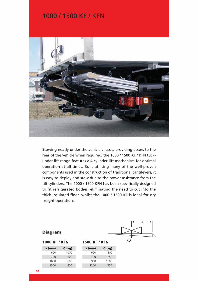
1000 / 1500 KF / KFN
a (mm) Q (kg)
600 1000
750 800
1000 600
1500 400
1000 KF / KFN 1500 KF / KFN
a (mm) Q (kg)
600 1500
720 1250
900 1000
1200 750
Diagram
Stowing neatly under the vehicle chassis, providing access to the
rear of the vehicle when required, the 1000 / 1500 KF / KFN tuck-
under lift range features a 4-cylinder lift mechanism for optimal
operation at all times. Built utilising many of the well-proven
components used in the construction of traditional cantilevers, it
is easy to deploy and stow due to the power assistance from the
tilt cylinders. The 1000 / 1500 KFN has been specifically designed
to fit refrigerated bodies, eliminating the need to cut into the
thick insulated floor, whilst the 1000 / 1500 KF is ideal for dry
freight operations.

Technical data 1000 KF / KFN 1500 KF / KFN
Lifting capacity 1000 kg 1500 kg
Main beam 180 x 180 mm 180 x 180 mm
Lifting gear hydraulics 2 x lift cylinder / 2 x tilt cylinder
Lift arm pitch 1310 mm 1310 mm
Load centre - lengthwise 600 mm 600 mm
Load centre - across center 50 % of the full load on one side
Inclination angle of the platform +10° to -10° +10° to -10°
61
Robust, well-proven, and ideal for refrigerated vehicles
Dimensions
WeightsPlatform type Alum.
Platform width (mm) 2300
Platform height (mm)
1210 435 kg
1355 453 kg
Platform type Steel
Platform width (mm) 2300
Platform height (mm)
1202 450 kg
1415 502 kg
Dim. K
Dim. D
Dim
ensi
on
H(lo
aded
/unl
.)
Dim
. FD
im. G
(load
ed/
unl.)
1000 / 1500 KF 1000 / 1500 KFN
Lenkerlängen (in mm) 800 900 1000 900 1000
H (max.) Loading height unloaded 1420 1546 1550 1546 1550
H (min.) Loading height loaded 972 1102 1172 1102 1230
F (max.) Middle of main beam to upper edge of loading floor
822 896 980 896 980
K (min.) At dimension F (max.) 694 763 815 806 860
D (min.) Installation space (min.) 1065-850 1215-1000 1130-1070 1245-1030 1320-1080
F (min.) 607 737 794 737 794
K (max.) At dimension F (min.) 910 937 1023 980 1065
G (max.) Unloaded (middle of main beam to ground)
598 650 570 650 570
G (min.) Loaded 365 365 378 365 440
E (max.) Vehicle frame width (max.) 1120 1120 1120 1120 1120
E (min.) Vehicle frame width (min.) 750 750 750 750 750
The specified weights apply to the lightest platforms of the corresponding height. You will find an overview of weights, lift arm lengths and general technical informationin the “Technical Appendix” starting on page 100. Subject to technical changes. Dimensions may vary.

62
1000 KUZ
a (mm) Q (kg) 700 1000
875 800
1150 600
1700 400
2400 250
The 1000 KUZ is a single-fold retractable tail lift. A push-pull cylinder
aligned lengthwise moves the lift into the desired position. The lift
leaves the factory fully assembled and with the lift unit KTL coated,
ready for clamping onto the chassis supplied with kits suitable for
trucks or trailers. Single fold platforms are available in a range of
sizes - either all aluminium or steel section with an aluminium
folding section. When stowed, the lift forms the vehicle’s under-
run bumper. The lift is entirely operated by a user friendly K-plus
control system and optional EasyMove control. Ideal for frequent use.
Diagram

63
The specified weights apply to the lightest platforms of the corresponding height. You will find an overview of weights, lift arm lengths and general technical informationin the “Technical Appendix” starting on page 100. Subject to technical changes. Dimensions may vary.
Retractable tail lift, single-fold, 1000 kg lifting capacity
Dimensions
Technical data
1000 KUZ
Lift arms (in mm) 700 800 900
H (max.) Loading height unloaded 1256 1409 1546
H (min.) Loading height loaded 906 922 998
F (max.) Middle of main beam to upper edge of loading floor 728 811 894
K (min.) At dimension F (max.) 515 570 626
D (min.) Installation space (min.) 1800 1800 1900
F (min.) 529 572 625
K (max.) At dimension F (min.) 710 801 886
G (max.) Unloaded (middle of main beam to ground) 528 598 652
G (min.) Loaded 377 350 373
E (max.) Vehicle frame width (max.) 920 920 920
E (min.) Vehicle frame width (min.) 645 645 645
1000 KUZ
Lifting capacity 1000 kg
Main beam 180 x 180 mm
Lifting gear hydraulics 2 x lift cylinder / 2 x tilt cylinder / 1 x moving cylinder
Lift arm pitch 760 / 1310 / 1490 mm
Load centre - lengthwise 700 mm
Load centre - across center 50 % of the full load on one side
Inclination angle of the platform +10° to -10°
WeightsPlatf. type Alum./Alum.
Platform width (mm) 2400
Platform height (mm)
1605 492 kg
1700 500 kg
Platf. type Steel/Alum.
Platform width (mm) 2400
Platform height (mm)
1600 522 kg
1700 530 kg
Weight of retraction unit 175 kgDim
ensi
on
H(lo
aded
/unl
.)
Dim
. FDim. D
Dim
. G(lo
aded
/unl
.)

a (mm) Q (kg) 600 1500
720 1250
900 1000
1200 750
The 1500 KLUZ is a robust lightweight retractable lift. A push-pull
cylinder aligned lengthwise moves the lift into the desired position.
The lift leaves the factory fully assembled and with the lift unit KTL
coated, ready for clamping onto the chassis supplied with kits
suitable for trucks or trailers. Single fold platforms are available
in a range of sizes – either all aluminium or steel section with an
aluminium folding section. When stowed, the lift forms the
vehicle’s underrun bumper. The lift is entirely operated by a user
friendly K-plus control system and optional EasyMove control. Ideal
for frequent use.
Diagram
64
1500 KLUZ

65
The specified weights apply to the lightest platforms of the corresponding height. You will find an overview of weights, lift arm lengths and general technical informationin the “Technical Appendix” starting on page 100. Subject to technical changes. Dimensions may vary.
Dimensions
Technical data
1500 KLUZ
Lift arms (in mm) 700 800 900
H (max.) Loading height unloaded 1256 1409 1546
H (min.) Loading height loaded 906 922 998
F (max.) Middle of main beam to upper edge of loading floor 728 811 894
K (min.) At dimension F (max.) 515 570 626
D (min.) Installation space (min.) 1800 1800 1900
F (min.) 529 572 625
K (max.) At dimension F (min.) 710 801 886
G (max.) Unloaded (middle of main beam to ground) 528 598 652
G (min.) Loaded 377 350 373
E (max.) Vehicle frame width (max.) 920 920 920
E (min.) Vehicle frame width (min.) 645 645 645
1500 KLUZ
Lifting capacity 1500 kg
Main beam 180 x 180 mm
Lifting gear hydraulics 2 x lift cylinder / 2 x tilt cylinder / 1 x moving cylinder
Lift arm pitch 750 / 1300 / 1490 mm
Load centre - lengthwise 600 mm
Load centre - across center 50 % of the full load on one side
Inclination angle of the platform +10° to -10°
WeightsPlatf. type Alum./Alum.
Platform width (mm) 2400
Platform height (mm)
1605 496 kg
1700 505 kg
Platf. type Steel/Alum.
Platform width (mm) 2400
Platform height (mm)
1600 527 kg
1700 535 kg
Weight of retraction unit 175 kg
Retractable tail lift, single-fold 1500 kg lifting capacity
Dim
ensi
on
H(lo
aded
/unl
.)
Dim
. FDim. D
Dim
. G(lo
aded
/unl
.)

a (mm) Q (kg) 1000 1500
1200 1250
1500 1000
1850 800
The 1500 KUZ is a robust retractable lift with 1000 mm load centre.
A push-pull cylinder aligned lengthwise moves the lift into the
desired position. The lift leaves the factory fully assembled and with
the lift unit KTL coated, ready for clamping onto the
chassis supplied with kits suitable for trucks or trailers. Single fold
platforms are available in a range of sizes - either all aluminium
or steel section with an aluminium folding section. When stowed,
the lift forms the vehicle’s underrun bumper. The lift is entirely
operated by a user friendly K-plus control system and optional
EasyMove control. Ideal for frequent use.
Diagram
66
1500 KUZ

67
The specified weights apply to the lightest platforms of the corresponding height. You will find an overview of weights, lift arm lengths and general technical informationin the “Technical Appendix” starting on page 100. Subject to technical changes. Dimensions may vary.
Dimensions
Technical data
1500 KUZ
Lift arms (in mm) 700 800 900 1000 1100
H (max.) Loading height unloaded 1200 1428 1548 1651 1793
H (min.) Loading height loaded 883 1011 1006 950 1023
F (max.) Middle of main beam to upper edge of loading floor 650 817 924 977 1056
K (min.) At dimension F (max.) 618 601 623 721 783
D (min.) Installation space (min.) 1800 1800 1900 1900 2000
F (min.) 508 566 614 569 608
K (max.) At dimension F (min.) 726 820 907 1040 1132
G (max.) Unloaded (middle of main beam to ground) 550 611 624 674 737
G (min.) Loaded 375 445 392 381 415
E (max.) Vehicle frame width (max.) 920 920 920 920 920
E (min.) Vehicle frame width (min.) 645 645 645 645 645
1500 KUZ
Lifting capacity 1500 kg
Main beam 180 x 180 mm
Lifting gear hydraulics 2 x lift cylinder / 2 x tilt cylinder / 1 x moving cylinder
Lift arm pitch 750 / 1300 / 1480 mm
Load centre - lengthwise 1000 mm
Load centre - across center 50 % of the full load on one side
Inclination angle of the platform +10° to -10°
WeightsPlatf. type Alum./Alum.
Platform width (mm) 2400
Platform height (mm)
1605 544 kg
1700 553 kg
Platf. type Steel/Alum.
Platform width (mm) 2400
Platform height (mm)
1600 575 kg
1700 583 kg
Weight of retraction unit 175 kg
Robust, retractable tail lift1500 kg lifting capacity
Dim
ensi
on
H(lo
aded
/unl
.)
Dim
. FDim. D
Dim
. G(lo
aded
/unl
.)

a (mm) Q (kg) 750 2000
900 1650
1100 1300
1600 950
The 2000 KLUZ is a robust lightweight retractable lift. A push-pull
cylinder aligned lengthwise moves the lift into the desired position.
The lift leaves the factory fully assembled and with the lift unit KTL
coated, ready for clamping onto the chassis supplied with kits suit-
able for trucks or trailers.
Single fold platforms are available in a range of sizes - either all
aluminium or steel section with an aluminium folding section.
When stowed, the lift forms the vehicle’s underrun bumper. The
lift is entirely operated by a user friendly K-plus control system
and optional EasyMove control. Ideal for frequent use.
Diagram
68
2000 KLUZ

69
The specified weights apply to the lightest platforms of the corresponding height. You will find an overview of weights, lift arm lengths and general technical informationin the “Technical Appendix” starting on page 100. Subject to technical changes. Dimensions may vary.
Dimensions
Technical data
2000 KLUZ
Lift arms (in mm) 700 800 900 1000 1100
H (max.) Loading height unloaded 1200 1428 1548 1651 1793
H (min.) Loading height loaded 883 1011 1006 950 1023
F (max.) Middle of main beam to upper edge of loading floor 650 817 924 977 1056
K (min.) At dimension F (max.) 618 601 623 721 783
D (min.) Installation space (min.) 1800 1800 1900 1900 2000
F (min.) 508 566 614 569 608
K (max.) At dimension F (min.) 726 820 907 1040 1132
G (max.) Unloaded (middle of main beam to ground) 550 611 624 674 737
G (min.) Loaded 375 445 392 381 415
E (max.) Vehicle frame width (max.) 920 920 920 920 920
E (min.) Vehicle frame width (min.) 645 645 645 645 645
2000 KLUZ
Lifting capacity 2000 kg
Main beam 180 x 180 mm
Lifting gear hydraulics 2 x lift cylinder / 2 x tilt cylinder / 1 x moving cylinder
Lift arm pitch 750 / 1300 / 1480 mm
Load centre - lengthwise 750 mm
Load centre - across center 50 % of the full load on one side
Inclination angle of the platform +10° to -10°
WeightsPlatf. type Alum./Alum.
Platform width (mm) 2400
Platform height (mm)
1605 546 kg
1700 555 kg
Platf. type Steel/Alum.
Platform width (mm) 2400
Platform height (mm)
1600 577 kg
1700 585 kg
Weight of retraction unit 175 kg
Robust retractable tail lift2000 kg lifting capacity
Dim
ensi
on
H(lo
aded
/unl
.)
Dim
. FDim. D
Dim
. G(lo
aded
/unl
.)

a (mm) Q (kg) 1000 2000
1200 1650
1500 1350
1800 1100
The 2000 KUZ is a robust retractable lift with 1000 mm load centre.
A push-pull cylinder aligned lengthwise moves the lift into the
desired position. Stowing ‘completely’ out of the way under
the rear of the vehicle it is ideal for fork lift and dock loading
operations. Suitable for dry freight and refrigerated applications.
The lift leaves the factory fully assembled and with the lift unit KTL
coated, ready for clamping onto the chassis supplied with kits
suitable for trucks or trailers. Single fold platforms are available in
a range of sizes - either all aluminium or steel section with an
aluminium folding section. When stowed, the lift forms the vehicle’s
underrun bumper. The lift is entirely operated by a user friendly
K-plus control system and optional EasyMove control. Ideal for
frequent use.
Diagram
70
2000 KUZ

71
The specified weights apply to the lightest platforms of the corresponding height. You will find an overview of weights, lift arm lengths and general technical informationin the “Technical Appendix” starting on page 100. Subject to technical changes. Dimensions may vary.
Dimensions
Technical data
2000 KUZ
Lift arms (in mm) 700 800 900 1000
H (max.) Loading height unloaded 1200 1428 1444 1651
H (min.) Loading height loaded 883 1011 1006 950
F (max.) Middle of main beam to upper edge of loading floor - - 820 977
K (min.) At dimension F (max.) 618 601 751 721
D (min.) Installation space (min.) 1800 1800 1900 1900
F (min.) - - 614 569
K (max.) At dimension F (min.) 726 820 907 1040
G (max.) Unloaded (middle of main beam to ground) - - 624 674
G (min.) Loaded - - 392 381
E (max.) Vehicle frame width (max.) 920 920 920 920
E (min.) Vehicle frame width (min.) 645 645 645 645
2000 KUZ
Lifting capacity 2000 kg
Main beam 180 x 180 mm
Lifting gear hydraulics 2 x lift cylinder / 2 x tilt cylinder / 1 x moving cylinder
Lift arm pitch 1300 mm
Load centre - lengthwise 1000 mm
Load centre - across center 50 % of the full load on one side
Inclination angle of the platform +10° to -10°
WeightsPlatf. type Alum./Alum.
Platform width (mm) 2400
Platform height (mm)
1605 548 kg
1700 557 kg
Platf. type Steel/Alum.
Platform width (mm) 2400
Platform height (mm)
1600 579 kg
1700 587 kg
Weight of retraction unit 175 kg
Robust retractable tail liftfor frequent use
Dim
ensi
on
H(lo
aded
/unl
.)
Dim
. FDim. D
Dim
. G(lo
aded
/unl
.)

72
2500 KLUZ
a (mm) Q (kg) 750 2500
900 2050
1100 1700
1600 1150
2400 750
The single-fold 2500 KLUZ features advanced technology and high
lifting capacity. A push-pull cylinder aligned lengthwise moves the
lift into the desired position. Stowing ‘completely’ out of the way
under the rear of the vehicle it is ideal for fork lift and dock loading
operations. Suitable for dry freight and refrigerated applications.
The lift leaves the factory fully assembled and with the lift unit KTL
coated, ready for clamping onto the chassis supplied with kits
suitable for trucks or trailers.
Single fold platforms are available in a range of sizes - either all
aluminium or steel section with an aluminium folding section. When
stowed, the lift forms the vehicle’s underrun bumper. The lift is en-
tirely operated by a user friendly K-plus control system and optional
EasyMove control. Ideal for frequent use.
Diagram

73
The specified weights apply to the lightest platforms of the corresponding height. You will find an overview of weights, lift arm lengths and general technical informationin the “Technical Appendix” starting on page 100. Subject to technical changes. Dimensions may vary.
Heavy duty designed for heavy loads
Dimensions
Technical data
2500 KLUZ
Lift arms (in mm) 700 800 900 1000
H (max.) Loading height unloaded 1200 1428 1444 1651
H (min.) Loading height loaded 883 1011 1006 950
F (max.) Middle of main beam to upper edge of loading floor - - 820 977
K (min.) At dimension F (max.) 618 601 751 721
D (min.) Installation space (min.) 1800 1800 1900 1900
F (min.) - - 614 569
K (max.) At dimension F (min.) 726 820 907 1040
G (max.) Unloaded (middle of main beam to ground) - - 624 674
G (min.) Loaded - - 392 381
E (max.) Vehicle frame width (max.) 920 920 920 920
E (min.) Vehicle frame width (min.) 645 645 645 645
2500 KLUZ
Lifting capacity 2500 kg
Main beam 180 x 180 mm
Lifting gear hydraulics 2 x lift cylinder / 2 x tilt cylinder / 1 x moving cylinder
Lift arm pitch 750 / 1300 / 1480 mm
Load centre - lengthwise 750 mm
Load centre - across center 50 % of the full load on one side
Inclination angle of the platform +10° to -10°
WeightsPlatf. type Alum./Alum.
Platform width (mm) 2400
Platform height (mm)
1605 550 kg
1700 559 kg
Platf. type Steel/Alum.
Platform width (mm) 2400
Platform height (mm)
1600 581 kg
1700 589 kg
Weight of retraction unit 175 kgDim
ensi
on
H(lo
aded
/unl
.)
Dim
. FDim. D
Dim
. G(lo
aded
/unl
.)

a (mm) Q (kg)
1200 2500
1400 2100
1600 1875
1800 1650
2400 1250
2500 KUZ 3000 KUZ
a (mm) Q (kg)
1000 3000
1200 2500
1500 2000
1800 1650
2400 1250
Diagram
Heavy duty retractable lift available in two capacities. Stowing
‘completely’ out of the way under the rear of the vehicle it is ideal
for fork lift and dock loading operations. Suitable for dry freight
and refrigerated applications.
The lift leaves the factory fully assembled ready for clamping onto
the trailer’s chassis. Single fold platforms are available in a range
of sizes, with steel section and aluminium folding section. When
stowed, the lift forms the vehicle’s underrun bumper.
The lift is entirely operated by a user friendly K-plus control system
and optional EasyMove control. Ideal for frequent use.
74
2500 KUZ / 3000 KUZ

75
The specified weights apply to the lightest platforms of the corresponding height. You will find an overview of weights, lift arm lengths and general technical informationin the “Technical Appendix” starting on page 100. Subject to technical changes. Dimensions may vary.
Heavy duty designed for heavy loads
Dimensions
Technical data
2500 / 3000 KUZ
Lift arms (in mm) 900
H (max.) Loading height unloaded 1554
H (min.) Loading height loaded 1030
F (max.) Middle of main beam to upper edge of loading floor 924
K (min.) At dimension F (max.) 654
D (min.) Installation space (min.) 1830
F (min.) 645
K (max.) At dimension F (min.) 901
G (max.) Unloaded (middle of main beam to ground) 630
G (min.) Loaded 358
E (max.) Vehicle frame width (max.) 935
E (min.) Vehicle frame width (min.) 650
2500 KUZ 3000 KUZ
Lifting capacity 2500 kg 3000 kg
Main beam 190 x 190 mm 190 x 190 mm
Lifting gear hydraulics 2 x lift cylinder / 2 x tilt cylinder / 1 x moving cylinder
Lift arm pitch 1300 mm 1300 mm
Load centre - lengthwise 1200 mm 1000 mm
Load centre - across center 50 % of the full load on one side
Inclination angle of the platform +10° to -10° +10° to -10°
Weights2500 KUZ Steel/Alum.
Platform width (mm) 2450
Platform height (mm)
1800 711 kg
2000 733 kg
3000 KUZ Steel/Alum.
Platform width (mm) 2450
Platform height (mm)
1800 715 kg
2000 737 kg
Weight of retraction unit 240 kgDim
ensi
on
H(lo
aded
/unl
.)
Dim
. FDim. D
Dim
. G(lo
aded
/unl
.)

a (mm) Q (kg)
1000 1500
1200 1250
1500 1000
1850 800
1500 TrailGate 2000 TrailGate
a (mm) Q (kg)
750 2000
900 1650
1100 1300
1600 950
Diagram
A specially designed retractable tail lift for easy assembly on semi-
trailers with a frame width of approximately 1300 mm.
An integrated aluminium bridgeplate can easily be modified to
avoid door locks and dock bumpers.
76
1500 / 2000 TrailGate

77
The specified weights apply to the lightest platforms of the corresponding height. You will find an overview of weights, lift arm lengths and general technical informationin the “Technical Appendix” starting on page 100. Subject to technical changes. Dimensions may vary.
Dimensions
Technical data
1500 / 2000 TrailGate
Lift arms (in mm) 800 900
H (max.) Loading height unloaded 1383 1441
H (min.) Loading height loaded 1011 1006
F (max.) Middle of main beam to upper edge of loading floor 772 817
K (min.) At dimension F (max.) 601 623
D (min.) Installation space (min.) 1924 2066
F (min.) 566 614
K (max.) At dimension F (min.) 820 907
G (max.) Unloaded (middle of main beam to ground) 611 624
G (min.) Loaded 445 392
E (max.) Vehicle frame width (max.) 1490 1490
E (min.) Vehicle frame width (min.) 1330 1330
1500 TrailGate 2000 TrailGate
Lifting capacity 1500 kg 2000 kg
Main beam 180 x 180 mm 180 x 180 mm
Lifting gear hydraulics 2 x lift cylinder / 2 x tilt cylinder / 1 x moving cylinder
Lift arm pitch 820 mm 820 mm
Load centre - lengthwise 1000 mm 750 mm
Load centre - across center 50 % of the full load on one side
Inclination angle of the platform +10° to -10° +10° to -10°
WeightsPlatf. type Steel/Alum.
Platform width (mm) 2400
Platform height (mm)
1700 503 kg
Weight of retraction unit 175 kg
The latest retractable tail lift –compact and easy to fit
Dim
ensi
on
H(lo
aded
/unl
.)
Dim
. FDim. D
Dim
. G(lo
aded
/unl
.)

a (mm) Q (kg)
1000 1500
1200 1250
1500 1000
1850 800
1500 TruckGate 2000 TruckGate
a (mm) Q (kg)
750 2000
900 1650
1100 1300
1600 950
Diagram
A specially designed retractable tail lift for easy assembly on
vehicles with a frame width of approximately 750 - 865 mm. The
guide rails are included in a frame and can be assembled without
requiring adjustment.
The platform is available in a range of sizes and models – either
all aluminium or steel section with an aluminium folding section.
78
1500 / 2000 TruckGate

79
The specified weights apply to the lightest platforms of the corresponding height. You will find an overview of weights, lift arm lengths and general technical informationin the “Technical Appendix” starting on page 100. Subject to technical changes. Dimensions may vary.
Dimensions
Technical data
1500 / 2000 TruckGate
Lift arms (in mm) 800 900
H (max.) Loading height unloaded 1428 1548
H (min.) Loading height loaded 1001 1006
F (max.) Middle of main beam to upper edge of loading floor 650 817
K (min.) At dimension F (max.) 618 601
D (min.) Installation space (min.) 1770 1870
F (min.) 508 566
K (max.) At dimension F (min.) 726 820
G (max.) Unloaded (middle of main beam to ground) 550 611
G (min.) Loaded 375 445
E (max.) Vehicle frame width (max.) 865 865
E (min.) Vehicle frame width (min.) 752 752
1500 TruckGate 2000 TruckGate
Lifting capacity 1500 kg 2000 kg
Main beam 180 x 180 mm 180 x 180 mm
Lifting gear hydraulics 2 x lift cylinder / 2 x tilt cylinder / 1 x moving cylinder
Lift arm pitch 1300 mm 1300 mm
Load centre - lengthwise 1000 mm 750 mm
Load centre - across center 50 % of the full load on one side
Inclination angle of the platform +10° to -10° +10° to -10°
Retractable “truck tail lift”
WeightsPlatf. type Alum./Alum.
Platform width (mm) 2400
Platform height (mm)
1605 470 kg
1700 479 kg
Platf. type Steel/Alum.
Platform width (mm) 2400
Platform height (mm)
1700 508 kg
Weight of retraction unit 175 kg
Dim
ensi
on
H(lo
aded
/unl
.)
Dim
. FDim. D
Dim
. G(lo
aded
/unl
.)

a (mm) Q (kg)
1000 1500
1200 1250
1500 1000
1850 800
1500 KUZK 2000 KUZK
a (mm) Q (kg)
750 2000
900 1650
1100 1300
1600 950
Diagram
Robust retractable lift available in two capacities specially
designed for drawbar applications. Stowing ‘completely’ out of
the way under the rear of the vehicle it is ideal for fork lift and
dock loading operations. Suitable for dry freight and refrigerated
applications.
The lift leaves the factory fully assembled ready for clamping onto
the chassis supplied with kits suitable for trucks or trailers. Single
fold platforms are available in a range of sizes - either all
aluminium or steel section with an aluminium folding section.
When stowed, the lift forms the vehicle’s underrun bumper.
The lift is entirely operated by a user friendly K-plus control system
and optional EasyMove control. Ideal for frequent use.
80
1500 / 2000 KUZK

81
The specified weights apply to the lightest platforms of the corresponding height. You will find an overview of weights, lift arm lengths and general technical informationin the “Technical Appendix” starting on page 100. Subject to technical changes. Dimensions may vary.
Dimensions
Technical data
1500 / 2000 KUZK
Lift arms (in mm) 700 800 900 1000 1100
H (max.) Loading height unloaded 1200 1428 1548 1651 1793
H (min.) Loading height loaded 883 1011 1006 950 1023
F (max.) Middle of main beam to upper edge of loading floor 650 817 924 977 1056
K (min.) At dimension F (max.) 618 601 623 721 783
D (min.) Installation space (min.) 1630 1740 1740 1840 1840
F (min.) 508 566 614 569 608
K (max.) At dimension F (min.) 726 820 907 1040 1132
G (max.) Unloaded (middle of main beam to ground) 550 611 624 674 737
G (min.) Loaded 375 445 392 381 415
E (max.) Vehicle frame width (max.) 1070 1070 1070 1070 1070
E (min.) Vehicle frame width (min.) 800 750 800 800 800
1500 KUZK 2000 KUZK
Lifting capacity 1500 kg 2000 kg
Main beam 180 x 180 mm 180 x 180 mm
Lifting gear hydraulics 2 x lift cylinder / 2 x tilt cylinder / 1 x moving cylinder
Lift arm pitch 700 - 1100 mm 700 - 1100 mm
Load centre - lengthwise 1000 mm 750 mm
Load centre - across center 50 % of the full load on one side
Inclination angle of the platform +0° to -10° +0° to -10°
Designed specifically for use withdrawbar trailers
WeightsPlatf. type Alum./Alum.
Platform width (mm) 2400
Platform height (mm)
1605 551 kg
1700 560 kg
Weight of retraction unit 175 kg
Platf. type Steel/Alum.
Platform width (mm) 2400
Platform height (mm)
1600 571 kg
1700 580 kg
Weight of retraction unit 190 kgDim
ensi
on
H(lo
aded
/unl
.)
Dim
. FDim. D
Dim
. G(lo
aded
/unl
.)

a (mm) Q (kg)
600 750
700 650
820 550
750 KUZFM 1000 KUZFM
a (mm) Q (kg)
600 1000
750 800
950 800
Diagram
Robust retractable lift available in two capacities with double
folding platform ideal for vehicles with short overhangs (from
985 mm). Stowing ‘completely’ out of the way under the rear of
the vehicle it is ideal for fork lift and dock loading operations.
Suitable for dry freight and refrigerated applications.
Due to its compact design this lift fits onto 3.5 tonne chassis.
The all aluminium platform is available in a range of depths, from
1050 to 1200 mm. When stowed, the lift forms the vehicle’s
underrun bumper. The lift is entirely operated by a user friendly
K-plus control system and optional EasyMove control. The folding
platform is spring-assisted. Ideal for frequent use.
82
750 / 1000 KUZFM

83
The specified weights apply to the lightest platforms of the corresponding height. You will find an overview of weights, lift arm lengths and general technical informationin the “Technical Appendix” starting on page 100. Subject to technical changes. Dimensions may vary.
Dimensions
Technical data
750 / 1000 KUZFM
Lift arms (in mm) 600
H (max.) Loading height unloaded 1000
H (min.) Loading height loaded 715
F (max.) Middle of main beam to upper edge of loading floor 550
K (min.) At dimension F (max.) 548
D (min.) Installation space (min.) 985*
F (min.) 385
K (max.) At dimension F (min.) 660
G (max.) Unloaded (middle of main beam to ground) 450
G (min.) Loaded 330
E (max.) Vehicle frame width (max.) 870
E (min.) Vehicle frame width (min.) 750
750 KUZFM 1000 KUZFM
Lifting capacity 750 kg 1000 kg
Main beam 180 x 180 mm 180 x 180 mm
Lifting gear hydraulics 2 x lift cylinder / 2 x tilt cylinder / 1 x moving cylinder
Lift arm pitch 1320 mm 1320 mm
Load centre - lengthwise 600 mm 600 mm
Load centre - across center 50 % of the full load on one side
Inclination angle of the platform +10° to -10° +10° to -10°
Weights750 KUZFM Alum./Alum.Platform width (mm) 2000
Platform height (mm)
1180 215 kg
1000 KUZFM Alum./Alum.
Platform width (mm) 2000
Platform height (mm)
1180 236 kg
Weight of retraction unit 90 kg
Double fold retractable, with compact design
Dim
ensi
on
H(lo
aded
/unl
.)
Dim
. FDim. D
Dim
. G(lo
aded
/un
l.)
* End of retraction rail

a (mm) Q (kg)
1000 1500
1200 1250
1500 1000
1850 800
1500 KUZFM 2000 KUZFM
a (mm) Q (kg)
750 2000
900 1650
1100 1300
1600 950
Diagram
The double fold 1500 / 2000 KUZFM tail lift is ideal for vehicles
with fixed or demountable bodies and short overhangs (minimum
1500 mm). Due to its compact design this lift perfectly fits onto
12 tonne chassis. A push-pull cylinder aligned lengthwise moves the
lift into the desired position. Upon request it leaves the factory fully
assembled and with the lift unit KTL coated, ready for clamping
onto the chassis supplied with kits suitable for trucks or trailers.
When stowed, the lift forms the vehicle’s underrun bumper. The
folding platform is spring-assisted. A bridging plate and various
other options are available.
84
1500 / 2000 KUZFM

85
The specified weights apply to the lightest platforms of the corresponding height. You will find an overview of weights, lift arm lengths and general technical informationin the “Technical Appendix” starting on page 100. Subject to technical changes. Dimensions may vary.
Dimensions
Technical data
1500 / 2000 KUZFM
Lift arms (in mm) 1040
H (max.) Loading height unloaded 1711
H (min.) Loading height loaded 1060
F (max.) Middle of main beam to upper edge of loading floor 1111
K (min.) At dimension F (max.) 536
D (min.) Installation space (min.) 1500
F (min.) 714
K (max.) At dimension F (min.) 1006
G (max.) Unloaded (middle of main beam to ground) 600
G (min.) Loaded 340
E (max.) Vehicle frame width (max.) 870
E (min.) Vehicle frame width (min.) 750
1500 KUZFM 2000 KUZFM
Lifting capacity 1500 kg 2000 kg
Main beam 180 x 180 mm 180 x 180 mm
Lifting gear hydraulics 2 x lift cylinder / 2 x tilt cylinder / 1 x moving cylinder / 1 x folding cylinder
Lift arm pitch 1300 mm 1300 mm
Load centre - lengthwise 1000 mm 750 mm
Load centre - across center 50 % of the full load on one side
Inclination angle of the platform +10° to -10° +10° to -10°
WeightsPlatf. type Alum./Alum.Platform width (mm) 2300
Platform height (mm)
1805 475 kg
Weight of retraction unit 175 kgDim
. FDim. D
Dim
. G(lo
aded
/un
l.)
Double fold retractable, easy to fit
Dim
ensi
on
H(lo
aded
/unl
.)

a (mm) Q (kg)
1000 1500
1200 1250
1500 1000
1850 800
1500 KUZF 2000 KUZF
a (mm) Q (kg)
750 2000
900 1650
1100 1300
1600 950
Diagram
Robust retractable lift with double folded platform ideal for
vehicles with demountable bodies and also fixed bodies with short
overhangs. The lift including the retraction unit leaves the factory
fully assembled with the lift unit powder coated. When
stowed, the lift forms the vehicle’s underrun bumper. The lift is
entirely operated by a user friendly K-plus control system and
optional EasyMove control. Ideal for frequent use.
Only the spring-assisted platform tip is unfolded manually. The
(automatic) adjustment to various container lengths is program-
mable. The platform has good emergency running properties. A
bridge plate and various other options are available.
86
1500 / 2000 KUZF

87
The specified weights apply to the lightest platforms of the corresponding height. You will find an overview of weights, lift arm lengths and general technical informationin the “Technical Appendix” starting on page 100. Subject to technical changes. Dimensions may vary.
Dimensions
Technical data
1500 / 2000 KUZF
Lift arms (in mm) 1040
H (max.) Loading height unloaded 1733
H (min.) Loading height loaded 1054
F (max.) Middle of main beam to upper edge of loading floor 1133
K (min.) At dimension F (max.) 536
D (min.) Installation space (min.) 1560
F (min.) 714
K (max.) At dimension F (min.) 1006
G (max.) Unloaded (middle of main beam to ground) 600
G (min.) Loaded 340
E (max.) Vehicle frame width (max.) 910
E (min.) Vehicle frame width (min.) 645
1500 KUZF 2000 KUZF
Lifting capacity 1500 kg 2000 kg
Main beam 180 x 180 mm 180 x 180 mm
Lifting gear hydraulics 2 x lift cylinder / 2 x tilt cylinder / 1 x moving cylinder / 1 x folding cylinder
Lift arm pitch 1300 mm 1300 mm
Load centre - lengthwise 1000 mm 750 mm
Load centre - across center 50 % of the full load on one side
Inclination angle of the platform +10° to -10° +10° to -10°
WeightsPlatf. type Alum./Alum.Platform width (mm) 2300
Platform height (mm)
1805 595 kg
Weight of retraction unit 175 kg
Dim
ensi
on
H(lo
aded
/unl
.)
Dim
. FDim. D
Dim
. G(lo
aded
/un
l.)
Double fold, hydraulicallyoperated retractable

88
MBB PALFINGER
Column lifts – standard features• Lifting capacity up to 4,000 kg
• Aluminium platform with steel frame for extra strength
• Steel components are shot blasted and KTL-coated
• 1200 mm load centre
• Power opening and closing
• Platform can be raised to any height up to vehicle roof
• Load safety device
• Conforms to CE regulations

89
Wide range of column lifts
Optional extras• Rear closure sealing kit
• Side and rear safety gates
• Additional internally mounted control switch
• Warning light in the cab if platform not closed
• Roll stops made to order
• Remote control
• Warning lights
• Top flap
• Circuitry for interior light
• Cycle counter
• Code protected operation
• Integrated rear lights
We offer a wide range of options allowing you to specifya lift ideally suited to your individual application

90
Column lifts, specialist and passenger lifts
MBB PALFINGER’s sister company, UK-based RATCLIFF PALFINGER,
offers a wide choice of interesting and high quality commercial
and passenger lifts to complement the existing MBB range. Besi-
des the innovative commercial column lift solutions for box bodies
as well as the specialist lifts for tipper and refrigerated vehicles
and double tier applications there is also an extensive range of
products for people with reduced mobility.

RQ QUICKFIT LIFT
• 1000 – 1500 kg capacity• Suitable for larger box bodied
vehicles and flatbeds• Pre-assembled for an easy and quick
installation• Lightweight Aluminium or steel
frames and platforms• Wide range of options including
ramps, safety gates etc.
RQ FLEXI-LIFT
• 500 kg capacity – versatile ‘mix and match’ range
• Designed for small box bodied vehicles
• Lightweight - weighs from 115 kg• Pre-assembled for an easy and quick
installation• Choose frame, platform and options
to suit meet your needs
91
Column lifts
RV OVERHEAD BEAM LIFT
• 500 – 1500 kg capacity• Compatible with barn door closures
– ideal for refrigerated vehicle applications
• Platform can be raised above vehicle floor level
• ‘Made to measure’ platforms including ½ width models
• Wide range of options
RQR REAR CLOSURE LIFT
• 500 – 1000 kg capacity• Fully pre-assembled tail lift incl.
glass fibre reinforced top flap panel• Very light platforms and lift frame
made of Aluminium• Easy installation - no shutters or
doors required• Different platform dimensions
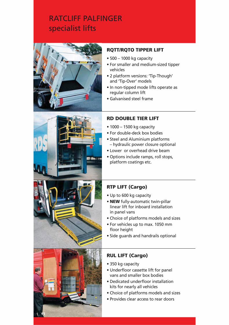
92
RATCLIFF PALFINGERspecialist lifts
RD DOUBLE TIER LIFT
• 1000 – 1500 kg capacity• For double-deck box bodies• Steel and Aluminium platforms
– hydraulic power closure optional• Lower or overhead drive beam• Options include ramps, roll stops,
platform coatings etc.
RQTT/RQTO TIPPER LIFT
• 500 – 1000 kg capacity• For smaller and medium-sized tipper
vehicles• 2 platform versions: ‘Tip-Though’
and ‘Tip-Over’ models• In non-tipped mode lifts operate as
regular column lift• Galvanised steel frame
RTP LIFT (Cargo)
• Up to 600 kg capacity• NEW fully-automatic twin-pillar
linear lift for inboard installation in panel vans
• Choice of platforms models and sizes• For vehicles up to max. 1050 mm
floor height• Side guards and handrails optional
RUL LIFT (Cargo)
• 350 kg capacity• Underfloor cassette lift for panel
vans and smaller box bodies • Dedicated underfloor installation
kits for nearly all vehicles • Choice of platforms models and sizes• Provides clear access to rear doors

RVT300 LIFT
• 300 kg capacity• Semi-automatic single-arm linear lift
for railway vehicles• Different versions available• Max. lifting height 1000 mm
93
Passenger lifts
RTP60 / RTP50 / RTP40 LIFT
• 600, 500 respectively 400 kg capacity• NEW fully-automatic twin-pillar
linear lift for inboard installation in vans and minibuses
• Choice of platforms models andsizes
• For vehicles up to max. 1050 mmfloor height
• Innovative safety features
RS300 LIFT
• 300 kg capacity• Semi-automatic step lift• Use as steps or as a lift• Specification with 1 up to 3 steps• Lifting height up to 1300 mm
RUL35 LIFT
• 350 kg capacity• Compact cassette lift for minibuses
and smaller coachbuilt bodies• Dedicated underfloor installation
kits for nearly all vehicles• Choice of platforms models and
sizes• Provides clear access to rear doors

94
The MEDILIFT range of fully automatic, electrically operated lifts
is designed for low-floor trams and buses, providing safe and easy
access for wheelchair users. The Medilift is particular useful in
areas with no pavements as all passengers, not only wheelchair
users, can enter the vehicle with ease.
Safety features• Automatic roll stop
• Sensitive edges for platform
• Control with integrated diagnostics
• Lift integrated in vehicle safety system
• Safeguard
• Warning stickers
• Antislip surface
• Outputs for buzzers and flashing lights
MEDILIFT

95
LB 300Fully automatic electric column lift
• for low-floor buses
R 3.3Fully automatic electriccassette lift
• for low-floor trams
The only fully automatic lift solutionfor low floor trams and buses
Width platform 1200 mm
Depth platform 870 mm
Height column 840 mm
Length platform ext. 1200 mm
Width platform ext. 925 m
Capacity 350 kg
Voltage 24 V
Current draw 30 A
Weight 200 kg
Width cassette 1300 mm
Depth cassette 785 mm
Heigth cassette 200 mm
Length platform ext. 1200 mm
Width platform ext. 900 mm
Capacity 300 kg
Voltage 24 V
Current draw 30 A
Weight 200 kg
Width platform 1050 mm
Depth platform 870 mm
Height column 840 mm
Length platform ext. 1200 mm
Width platform ext. 925 mm
Capacity 350 kg
Voltage 24 V
Current draw 30 A
Weight 170 kg
SB 300Fully automatic electric column lift
• for low-floor trams

The range of MEDIRAMPE ramps includes both fully automaticand manually operated models designed for use in low-floortrams and buses providing easy and safe access for wheelchairusers.
The innovative modular ramp FVM, for integrated installation
into the vehicle floor, features an extra low height of only 60 mm
and a “quick fit frame” for fast and easy maintenance of the
ramp. The well-proven tooth-belt drive is used for the FVM ramp.
96
MEDIRAMPE

97
M 1200Manually operated cassette ramp
• for installation under thevehicle floor (retrofit)
EURONFully automatic electriccassette ramp
• for installation under the vehicle floor (retrofit)
Length cassette 850 mm
Width cassette 1040 mm
Height cassette 74 / 60 mm
Length ramp 350 / 690 mm
Width ramp 920 mm
Capacity 350 kg
Voltage 24 V
Weight 56 kg
Ext./Rectraction time 4.5 sec.
Length cassette 1482 mm
Width cassette 1137 mm
Height cassette 80 mm
Length ramp 1170 mm
Width ramp 920 mm
Capacity 350 kg
Voltage 24 V
Weight 65 kg
Ext./Rectraction time 8 sec.
Length cassette 1509 mm
Width cassette 1076 mm
Height cassette 66 mm
Length ramp 1150 mm
Width ramp 920 mm
Capacity 350 kg
Voltage -
Weight 70 kg
Ext./Rectraction time 10 sec.
FV 850/ FVM 850Fully automatic electric cassette ramp
• for integrated installation into the vehicle floor
MEDIRAMPE ramps – well-provenfor more than 20 years

98
TRAINLIFT
The range of semi-automatic trainlifts provides safe and easy
access for wheelchair users travelling by rail. Stowed neatly inside
the entrance to the carriage, the platform pivots round and
lowers, bridging the gap between the carriage floor and the
platform. For reasons of safety the lift is stowed locked and can
only be operated by authorised personnel. The Trainlift is
designed for lifting up to 1200 mm.
Safety features• Automatic roll stop
• Gravity down
• Lockable cover
• Warning stickers + Antislip surface
• Position detection for operation
• Pressure limiting valve
Technical specification• Steel frame
• Customized cover design
• Light aluminium sandwich platform
• Manual hydraulic pump for emergency
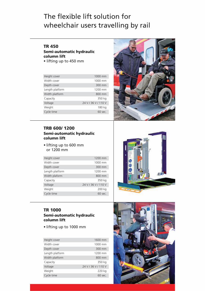
99
TR 1000Semi-automatic hydrauliccolumn lift
• lifting up to 1000 mm
TRB 600/ 1200Semi-automatic hydrauliccolumn lift
• lifting up to 600 mm or 1200 mm
Height cover 1000 mm
Width cover 1000 mm
Depth cover 300 mm
Length platform 1200 mm
Width platform 800 mm
Capacity 350 kg
Voltage 24 V / 36 V / 110 V
Weight 180 kg
Cycle time 60 sec.
Height cover 1200 mm
Width cover 1000 mm
Depth cover 300 mm
Length platform 1200 mm
Width plaform 800 mm
Capacity 350 kg
Voltage 24 V / 36 V / 110 V
Weight 200 kg
Cycle time 60 sec.
Height cover 1600 mm
Width cover 1000 mm
Depth cover 300 mm
Length platform 1200 mm
Width platform 800 mm
Capacity 350 kg
Voltage 24 V / 36 V / 110 V
Weight 220 kg
Cycle time 60 sec.
TR 450Semi-automatic hydraulic column lift • lifting up to 450 mm
The flexible lift solution for wheelchair users travelling by rail

100
Technical Appendix
All the tail lifts offered in the catalogue comply with the EC Directive for machinery 98/37/EC.
The underrun bumper is approved in accordance with the EC
Directive 70/221/EC.
Dimensions may vary.
Subject to technical changes.
General technical information
Lift and descent speed max. 0.15 m/s
Opening and closing speed max. 10° /s
Inclination speed max. 4° /s

101
Typ
e
Bat
tery
cap
acit
y 12
V
Bat
tery
cap
acit
y 24
V
R
eco
mm
end
ed c
apac
ity
Pow
er o
f
M
ax. o
per
atin
g p
ress
ure
Pum
p c
apac
ity
O
f th
e al
tern
ato
r
Po
wer
pac
k m
oto
r
A
h
Ah
W
att
Wat
t
bar
c
m³
/ re
volu
tio
n
Trad
itio
nal
can
tile
vers
500
min
ifix
1
43
105
80
0
800
200
1
1000
ATH
LET
quat
tro
143
105
63
0
200
0
200
1
500
/ 750
M
1
43
105
63
0
800
200
1
1000
E
143
10
5
630
2
000
1000
K
143
10
5
730
2
000
2
00
2
1500
KL
180
14
3
730
2
000
2
00
2
1500
K
180
18
0
1
000
20
00
200
2 /
3
2000
KL
180
18
0
1
000
20
00
200
2 /
3
2000
K
180
18
0
1
000
20
00
200
2 /
3
2500
KL
180
18
0
1
000
20
00
210
2 /
3
1500
/ 20
00 K
K
180
180
100
0
2000
2
00
2
/ 3
1500
/ 20
00 K
S
180
180
100
0
2000
2
00
2
/ 3
2500
KK
180
18
0
1
000
20
00
210
2
2500
/ 30
00 K
1
80
180
100
0
2000
2
10
3
500
/ 750
K 1
T L/
R
143
20
5
800
8
00
20
0
1
1000
AQ
1/2
T L/
R
14
3
2
05
630
8
00
20
0
1
Fold
able
tai
l lif
ts
1500
Tw
inFo
ld
143
10
5
730
2
000
2
00
2
1000
/ 15
00 K
F / K
FN
14
3
1
05
630
2
000
2
00
2
Tech
nic
al
tab
le –
Ele
ctri
cal
data
1000
K 1
/2T
L/R
14
3
2
05
730
2
000
2
00
2
Subj
ect
to t
echn
ical
cha
nges
. Spe
cific
atio
ns a
re n
on-b
indi
ng. V
aryi
ng t
ail l
ift c
onfig
urat
ions
can
res
ult
in d
iscr
epan
cies
in w
eigh
t.

102
Typ
e
Bat
tery
cap
acit
y 12
V
Bat
tery
cap
acit
y 24
V
R
eco
mm
end
ed c
apac
ity
Pow
er o
f
M
ax. o
per
atin
g p
ress
ure
Pum
p c
apac
ity
O
f th
e al
tern
ato
r
Po
wer
pac
k m
oto
r
A
h
Ah
W
att
Wat
t
bar
c
m³
/ re
volu
tio
n
Ret
ract
able
tai
l lif
ts
1000
KU
Z
14
3
1
05
630
2
000
2
00
2
1500
KU
Z
18
0
1
80
1
000
20
00
200
2
1500
KLU
Z
143
10
5
730
2
000
2
00
2
2000
KLU
Z
180
18
0
1
000
20
00
200
2
2000
KU
Z
18
0
1
80
1
000
20
00
200
2
2500
KLU
Z
180
18
0
1
000
20
00
200
2
2500
KU
Z
18
0
1
80
1
000
20
00
200
2
3000
KU
Z
18
0
1
80
1
000
20
00
210
3
1500
/ 20
00 T
railG
ate
1
80
180
100
0
2000
2
00
2
1500
/ 20
00 T
ruck
Gat
e
180
180
100
0
2000
2
00
2
1500
KU
ZK /
2000
KU
ZK
1
80
180
100
0
2000
2
00
2
750
/ 100
0 K
UZF
M
143
10
5
630
2
000
2
00
1
1500
/ 20
00 K
UZF
M
1
80
180
100
0
2000
2
00
2
1500
/ 20
00 K
UZF
1
80
180
100
0
2000
2
30
2
Tech
nic
al
tab
le –
Ele
ctri
cal
data
Subj
ect
to t
echn
ical
cha
nges
. Spe
cific
atio
ns a
re n
on-b
indi
ng. V
aryi
ng t
ail l
ift c
onfig
urat
ions
can
res
ult
in d
iscr
epan
cies
in w
eigh
t.

103
Plat
form
typ
e: A
lum
iniu
m
ATH
LET
quat
tro
Wid
th in
mm
140
0
220
0
240
0
250
0
250
0
250
0
250
0
250
0
25
00
250
0
250
0
250
0
240
0
24
00
Hei
ght
in m
m
1200
20
0*
1550
21
3*
28
2
3
77
3
76
3
90
5
07
5
09
5
11
5
13
6
71
5
32
1450
20
9*
1575
154
1700
289
38
4
3
98
5
16
5
18
5
20
5
22
6
80
5
41
1820
70
9
1825
295
391
390
404
524
526
528
530
690
549
1950
4
10
5
32
5
34
5
36
5
38
6
96
5
57
2050
40
1
4
15
5
39
5
41
5
43
5
45
7
03
5
64
8
09
2070
72
1
2200
4
23
5
48
5
50
5
52
5
54
7
12
5
72
8
21
7
37
2300
555
557
559
561
719
580
2400
565
567
569
571
729
590
2450
78
0
2650
581
583
585
587
745
606
Min
imum
wei
ghts
in k
g, *
11 k
g ad
ditio
nal w
eigh
t fo
r 3-
piec
e un
derr
un b
umpe
r
Tech
nic
al
tab
le –
Overv
iew
of
weig
hts
of
trad
itio
nal
can
tile
vers
Typ
es50
0 m
inif
ix
500
/ 75
0 M
1
000
10
00 E
100
0 K
150
0 K
L
1
500
K
2
000
KL
200
0 K
250
0 K
L
1
500
/ 20
00 K
K
1500
/ 2
000
KS
250
0 K
K
2
500
/ 30
00 K
Min
imum
wei
ghts
in k
g (li
ftin
g un
it w
eigh
t +
pla
tfor
m w
eigh
t of
ligh
test
mod
el)
Subj
ect
to t
echn
ical
cha
nges
. Spe
cific
atio
ns a
re n
onbi
ndin
g. V
aryi
ng t
ail l
ift c
onfig
urat
ions
can
res
ult
in d
iscr
epan
cies
in w
eigh
t.

104
Typ
es10
0010
00 K
1
500
KL
1500
K
200
0 K
L
200
0 K
250
0 K
L
1
500
/ 20
00 K
K
150
0 /
2000
KS
2
500
KK
250
0 /
3000
K
Plat
form
typ
e: S
teel
ATH
LET
qu
attr
o
Plat
form
wid
th in
mm
24
00
250
0
2500
2
500
2
500
2
500
2
400
2
500
25
00
240
0
240
0
Plat
form
hei
ght
in m
m
1209
312
1809
402
559
5
68
66
0
66
3
66
5
66
8
80
7
681
1
000
9
07
1509
357
519
5
28
62
0
62
3
62
5
63
0
76
7
641
2009
1
031
9
38
2109
608
700
703
705
706
847
7
21
2409
743
745
749
887
7
61
109
4
100
1
Min
imum
wei
ghts
in k
g
Tech
nic
al
tab
le –
Overv
iew
of
weig
hts
of
trad
itio
nal
can
tile
vers
Min
imum
wei
ghts
in k
g (li
ftin
g un
it w
eigh
t +
pla
tfor
m w
eigh
t of
ligh
test
mod
el)
Subj
ect
to t
echn
ical
cha
nges
. Spe
cific
atio
ns a
re n
onbi
ndin
g. V
aryi
ng t
ail l
ift c
onfig
urat
ions
can
res
ult
in d
iscr
epan
cies
in w
eigh
t.

105
Typ
es50
0 /
750
K 1
T R
/L
100
0 A
THLE
T q
uat
tro
1/2
T L/
R
1
000
K 1
/2T
L/R
Plat
form
typ
e: A
lum
iniu
m
Plat
form
wid
th in
mm
1000
1700
1000
Plat
form
hei
ght
in m
m
1450
202
259
317
1600
205
267
320
1550
204
263
319
1825
209
271
324
Tech
nic
al
tab
le–
Overv
iew
of
weig
hts
of
speci
al
tail
lif
ts
Typ
esTw
inFo
ld
1
000
KF
/ K
FN
150
0 K
F /
KFN
Plat
form
typ
e: A
lum
iniu
m/A
lum
iniu
m
Plat
form
wid
th in
mm
2300
2300
2300
Plat
form
hei
ght
in m
m
1210
424
428
435
Plat
form
typ
e: S
teel
/Alu
m.
1355
442
446
453
Plat
form
wid
th in
mm
2300
2300
2300
Plat
form
hei
ght
in m
m
1202
443
450
1210
468
1415
491
495
502
Min
imum
wei
ghts
in k
g
Tech
nic
al
tab
le–
Overv
iew
of
weig
hts
of
fold
ab
le t
ail
lif
ts
Min
imum
wei
ghts
in k
g (li
ftin
g un
it w
eigh
t +
pla
tfor
m w
eigh
t of
ligh
test
mod
el)
Subj
ect
to t
echn
ical
cha
nges
. Spe
cific
atio
ns a
re n
onbi
ndin
g. V
aryi
ng t
ail l
ift c
onfig
urat
ions
can
res
ult
in d
iscr
epan
cies
in w
eigh
t.

106
Typ
es10
00 K
UZ
1
500
KLU
Z
150
0 K
UZ
2
000
KLU
Z
200
0 K
UZ
2
500
KLU
Z
1500
/ 2
000
150
0 /
2000
75
0 K
UZF
M
1
000
KU
ZFM
150
0 /
2000
15
00 /
200
0
T
ruck
Gat
e
K
UZK
KU
ZFM
KU
ZF
Plat
form
typ
e: A
lum
iniu
m/A
lum
iniu
m
Plat
form
wid
th in
mm
2400
240
0
2
400
240
0
2
400
240
0
2
400
240
0
2
000
200
0
2
300
230
0
Plat
form
hei
ght
in m
m
1505
1180
2
15
236
1605
492
4
96
544
54
6
548
55
0
470
55
1
1700
500
5
05
553
55
5
557
55
9
479
56
0
1805
475
5
95
Wei
ght
of r
etra
ctio
n un
it17
5
175
17
5
175
1
75
175
1
75
175
9
0
90
1
75
175
Typ
es10
00 K
UZ
1
500
KLU
Z
150
0 K
UZ
2
000
KLU
Z
200
0 K
UZ
2
500
KLU
Z
250
0 K
UZ
3
000
KU
Z
150
0 /
2000
1
500
/ 20
00
1
500
/ 20
00
Tra
ilGat
e
Tr
uck
Gat
e
K
UZK
Plat
form
typ
e: S
teel
/Alu
m.
Plat
form
wid
th in
mm
2400
240
0
2
400
240
0
2
400
240
0
2
450
245
0
2
400
240
0
2
400
Plat
form
hei
ght
in m
m
1700
530
5
35
583
58
5
587
58
9
50
3
508
58
0
1600
522
5
27
575
57
7
579
58
1
5
71
1800
71
1
715
2000
73
3
737
Wei
ght
of r
etra
ctio
n un
it17
5
175
17
5
175
1
75
175
2
40
240
1
75
175
17
5
Min
imum
wei
ghts
in k
g
Tech
nic
al
tab
le–
Overv
iew
of
weig
hts
of
retr
act
ab
le t
ail
lif
ts
Min
imum
wei
ghts
in k
g (li
ftin
g un
it w
eigh
t +
pla
tfor
m w
eigh
t of
ligh
test
mod
el)
Subj
ect
to t
echn
ical
cha
nges
. Spe
cific
atio
ns a
re n
onbi
ndin
g. V
aryi
ng t
ail l
ift c
onfig
urat
ions
can
res
ult
in d
iscr
epan
cies
in w
eigh
t.

107
Typ
es50
0 m
inif
ix
500
/ 7
50 M
1000
ATH
LET
qu
attr
o
100
0 E
100
0 K
150
0 K
L
Lift
arm
len
gth
s in
mm
500
550
600
700
7
00
700
800
9
00
7
00
80
0
90
0
H (m
ax.)
780
960
1
100
1
210
12
00
1256
1
409
15
46
125
6
140
9
154
6
H (m
in.)
450
700
750
830
8
25
906
922
9
98
9
06
92
2
99
8
F (m
ax.)
340
510
620
650
6
50
728
811
8
94
7
28
81
1
89
4
D (m
in.)
729
543
617
742
7
73
665
720
7
76
6
65
72
0
77
6
K (m
in.)
546
452
467
592
6
03
515
570
6
26
5
15
57
0
62
6
F (m
in.)
370
420
500
5
00
529
572
6
25
5
29
57
2
62
5
K (m
ax.)
555
652
721
7
16
710
801
8
86
7
10
80
1
88
6
D (m
ax.)
646
802
871
8
86
860
951
1
036
860
951
1
036
Typ
es
1
500
K
2
000
KL
Lift
arm
len
gth
s in
mm
700
800
900
1
000
11
00
700
800
9
00
10
00
110
0
H (m
ax.)
1200
1
428
1
548
1
651
17
93
1200
1
428
15
48
165
1
179
3
H (m
in.)
883
941
1
006
9
50
102
3
883
1
011
10
06
95
0
102
3
F (m
ax.)
650
817
924
977
1
056
6
50
81
7
924
977
1
056
D (m
in.)
768
751
773
872
9
33
768
751
7
73
8
72
93
3
K (m
in.)
618
601
623
722
7
83
618
601
6
23
7
22
78
3
F (m
in.)
508
566
614
569
6
08
508
566
6
14
5
69
60
8
K (m
ax.)
726
820
907
1
041
11
32
726
820
9
07
10
41
113
2
D (m
ax.)
876
970
1
057
1
191
12
82
876
970
1
057
1
191
1
282
Tech
nic
al
tab
le–
Lift
arm
len
gth
s o
f tr
ad
itio
nal
can
tile
vers
Exp
lan
atio
ns:
H (m
ax.):
Loa
ding
hei
ght
unlo
aded
H (m
in.):
Loa
ding
hei
ght
load
ed
F
(max
.): M
iddl
e of
mai
n be
am t
o up
per
edge
of
load
ing
floor
K
(min
.): A
t di
men
sion
F (m
ax.)
D
(min
.): In
stal
latio
n sp
ace
(min
.)
F (m
in.)
K (m
ax.):
At
dim
ensi
on F
(min
.)
D (m
ax.):
Inst
alla
tion
spac
e (m
in.)
Subj
ect
to t
echn
ical
cha
nges
. Spe
cific
atio
ns a
re n
onbi
ndin
g. V
aryi
ng t
ail l
ift c
onfig
urat
ions
can
res
ult
in d
iscr
epan
cies
in w
eigh
t.

108
Typ
es15
00 /
200
0 K
S20
00 K
2500
KL
Lift
arm
len
gth
s in
mm
750
8
00
850
95
0
700
80
0
900
100
0
7
00
800
9
00
1000
H (m
ax.)
1340
141
6
1
505
165
7
1
160
134
5
1444
165
1
1
160
134
5
1
444
165
1
H (m
in.)
1127
116
5
1
204
128
1
883
94
1
100
6
9
50
883
9
41
1006
95
0
F (m
ax.)
858
9
04
967
106
1
650
78
5
820
97
7
650
7
85
820
9
77
D (m
in.)
563
5
84
560
59
4
768
79
1
901
87
2
768
7
91
901
8
72
K (m
in.)
413
4
34
410
44
4
618
64
1
751
72
2
618
6
41
751
7
22
F (m
in.)
742
7
80
819
89
6
508
56
6
614
56
9
508
5
66
614
5
69
K (m
ax.)
602
6
35
666
73
0
726
82
0
907
104
1
7
26
820
9
07
1041
D (m
ax.)
752
7
85
816
88
0
876
97
0
105
7
1
191
876
9
70
1057
119
1
Typ
es15
00 /
200
0 K
K
2500
KK
2
500
/ 30
00 K
5
00 /
750
K 1
T L/
R
1000
ATH
LET
qu
attr
o 1
/2T
L/R
1000
K 1
/2T
L/R
Lift
arm
len
gth
s in
mm
1100
110
0
9
00
1
000
60
0
700
700
700
H (m
ax.)
1793
157
7
1
554
174
8
1
120
126
3
121
0
12
56
H (m
in.)
1023
83
5
1
030
118
0
710
75
9
83
0
9
06
F (m
ax.)
1056
84
0
924
102
7
620
70
3
65
0
7
28
D (m
in.)
1028
114
5
8
09
834
5
32
588
742
664
K (m
in.)
783
10
10
6
54
679
4
17
473
592
514
F (m
in.)
608
4
20
645
79
5
380
42
9
50
0
5
29
K (m
ax.)
1132
118
9
9
01
922
6
23
711
721
710
D (m
ax.)
1377
132
4
1
056
107
7
738
82
6
87
1
8
60
Tech
nic
al
tab
le–
Lift
arm
len
gth
s o
f tr
ad
itio
nal
can
tile
vers
Exp
lan
atio
ns:
H (m
ax.):
Loa
ding
hei
ght
unlo
aded
H (m
in.):
Loa
ding
hei
ght
load
ed
F
(max
.): M
iddl
e of
mai
n be
am t
o up
per
edge
of
load
ing
floor
K
(min
.): A
t di
men
sion
F (m
ax.)
D
(min
.): In
stal
latio
n sp
ace
(min
.)
F (m
in.)
K (m
ax.):
At
dim
ensi
on F
(min
.)
D (m
ax.):
Inst
alla
tion
spac
e (m
in.)
Subj
ect
to t
echn
ical
cha
nges
. Spe
cific
atio
ns a
re n
onbi
ndin
g. V
aryi
ng t
ail l
ift c
onfig
urat
ions
can
res
ult
in d
iscr
epan
cies
in w
eigh
t.

109
Typ
es10
00 /
150
0 10
00 /
150
0 K
F10
00 /
150
0 K
FN10
00 K
UZ
1500
KLU
Z
Twin
Fold
Lift
arm
len
gth
s in
mm
900
8
00
900
100
0
900
100
0
700
80
0
900
7
00
800
9
00
H (m
ax.)
1500
142
0
1
546
155
0
1
546
155
0
1256
140
9
1
546
125
6
1
409
154
6
H (m
in.)
-
972
110
2
1
172
110
2
1
230
9
06
922
99
8
906
9
22
998
K (m
in.)
820
6
94
763
81
5
806
86
0
515
57
0
626
5
15
570
6
26
F (m
ax.)
850
8
22
896
98
0
896
98
0
728
81
1
894
7
28
811
8
94
D (m
in.)
K+
340
10
65-8
50
121
5-10
00
113
0-10
70
124
5-10
30
1320
-108
0
180
0
1
800
190
0
1
800
180
0
1
900
F (m
in.)
737
6
07
737
79
4
737
79
4
529
57
2
625
5
29
572
6
25
K (m
ax.)
955
9
10
937
102
3
980
106
5
710
80
1
886
7
10
801
8
86
G (m
ax.)
650
5
98
650
57
0
650
57
0
528
59
8
652
5
28
598
6
52
G (m
in.)
400
3
65
365
37
8
365
44
0
377
35
0
373
3
77
350
3
73
E (m
ax.)
870
11
20
1
120
112
0
1
120
112
0
920
92
0
920
9
20
920
9
20
E (m
in.)
650
7
50
750
75
0
750
75
0
645
64
5
645
6
45
645
6
45
Tech
nic
al
tab
le–
Lift
arm
len
gth
s o
f fo
ldab
le a
nd
retr
act
ab
le t
ail
lif
ts
Exp
lan
atio
ns:
H (m
ax.):
Loa
ding
hei
ght
unlo
aded
H (m
in.):
Loa
ding
hei
ght
load
ed
F (m
ax.):
Mid
dle
of m
ain
beam
to
uppe
r ed
ge o
f lo
adin
g flo
or
K
(min
.): A
t di
men
sion
F (m
ax.)
D (m
in.):
Inst
alla
tion
spac
e (m
in.)
F (m
in.)
K (m
ax.):
At
dim
ensi
on F
(min
.)
G
(max
.): U
nloa
ded
(mid
dle
of m
ain
beam
to
grou
nd)
G (m
in.):
Loa
ded
E
(max
.): V
ehic
le f
ram
e w
idth
(max
.)E
(min
.) Ve
hicl
e fr
ame
wid
th (m
in.)
Subj
ect
to t
echn
ical
cha
nges
. Spe
cific
atio
ns a
re n
onbi
ndin
g. V
aryi
ng t
ail l
ift c
onfig
urat
ions
can
res
ult
in d
iscr
epan
cies
in w
eigh
t.

110
Typ
es15
00 K
UZ
2000
KLU
Z
Lift
arm
len
gth
s in
mm
700
8
00
900
100
0
1
100
700
8
00
900
100
0
1
100
H (m
ax.)
1200
142
8
1
548
165
1
1
793
120
0
1428
154
8
1
651
179
3
H (m
in.)
883
10
11
1
006
950
10
23
8
83
101
1
1
006
950
10
23
K (m
in.)
618
6
01
623
72
1
783
61
8
601
62
3
721
7
83
F (m
ax.)
650
8
17
924
97
7
1056
650
8
17
924
97
7
1056
D (m
in.)
1800
180
0
1
900
190
0
2
000
180
0
1800
190
0
1
900
200
0
F (m
in.)
508
5
66
614
56
9
608
50
8
566
61
4
569
6
08
K (m
ax.)
726
8
20
907
104
0
1
132
726
8
20
907
104
0
1
132
G (m
ax.)
550
6
11
624
67
4
737
55
0
611
62
4
674
7
37
G (m
in.)
375
4
45
392
38
1
415
37
5
445
39
2
381
4
15
E (m
ax.)
920
9
20
920
92
0
920
92
0
20
9
20
920
9
20
E (m
in.)
645
6
45
645
64
5
645
64
5
645
64
5
645
6
45
Tech
nic
al
tab
le–
Lift
arm
len
gth
s o
f fo
ldab
le a
nd
retr
act
ab
le t
ail
lif
ts
Exp
lan
atio
ns:
H (m
ax.):
Loa
ding
hei
ght
unlo
aded
H (m
in.):
Loa
ding
hei
ght
load
ed
F (m
ax.):
Mid
dle
of m
ain
beam
to
uppe
r ed
ge o
f lo
adin
g flo
or
K
(min
.): A
t di
men
sion
F (m
ax.)
D (m
in.):
Inst
alla
tion
spac
e (m
in.)
F (m
in.)
K (m
ax.):
At
dim
ensi
on F
(min
.)
G
(max
.): U
nloa
ded
(mid
dle
of m
ain
beam
to
grou
nd)
G (m
in.):
Loa
ded
E
(max
.): V
ehic
le f
ram
e w
idth
(max
.)E
(min
.) Ve
hicl
e fr
ame
wid
th (m
in.)
Subj
ect
to t
echn
ical
cha
nges
. Spe
cific
atio
ns a
re n
onbi
ndin
g. V
aryi
ng t
ail l
ift c
onfig
urat
ions
can
res
ult
in d
iscr
epan
cies
in w
eigh
t.

111
Typ
es20
00 K
UZ
2500
KLU
Z25
00 K
UZ
3000
KU
Z15
00 /
200
0 Tr
ailG
ate
Lift
arm
len
gth
s in
mm
700
8
00
900
100
0
700
80
0
900
100
0
9
00
900
8
00
900
H (m
ax.)
1200
142
8
1
444
165
1
1
200
142
8
1444
165
1
1
554
155
4
1
383
144
1
H (m
in.)
883
10
11
1
006
950
8
83
1
011
10
06
9
50
1
030
103
0
1
011
100
6
K (m
in.)
618
6
01
751
72
1
618
60
1
751
72
1
654
6
54
601
6
23
F (m
ax.)
8
20
977
820
97
7
924
9
24
772
8
17
D (m
in.)
1800
180
0
1
900
190
0
1
800
180
0
1900
190
0
1
830
183
0
1
924
206
6
F (m
in.)
6
14
569
614
56
9
645
6
45
566
6
14
K (m
ax.)
726
8
20
907
104
0
726
82
0
907
104
0
9
01
901
8
20
907
G (m
ax.)
6
24
674
624
67
4
630
6
30
611
6
24
G (m
in.)
3
92
381
392
38
1
358
3
58
445
3
92
E (m
ax.)
920
9
20
920
92
0
920
92
0
920
92
0
935
9
35
1490
149
0
E (m
in.)
645
6
45
645
64
5
645
64
5
645
64
5
650
6
50
1330
133
0
Tech
nic
al
tab
le–
Lift
arm
len
gth
s o
f fo
ldab
le a
nd
retr
act
ab
le t
ail
lif
ts
Exp
lan
atio
ns:
H (m
ax.):
Loa
ding
hei
ght
unlo
aded
H (m
in.):
Loa
ding
hei
ght
load
ed
F (m
ax.):
Mid
dle
of m
ain
beam
to
uppe
r ed
ge o
f lo
adin
g flo
or
K
(min
.): A
t di
men
sion
F (m
ax.)
D (m
in.):
Inst
alla
tion
spac
e (m
in.)
F (m
in.)
K (m
ax.):
At
dim
ensi
on F
(min
.)
G
(max
.): U
nloa
ded
(mid
dle
of m
ain
beam
to
grou
nd)
G (m
in.):
Loa
ded
E
(max
.): V
ehic
le f
ram
e w
idth
(max
.)E
(min
.) Ve
hicl
e fr
ame
wid
th (m
in.)
Subj
ect
to t
echn
ical
cha
nges
. Spe
cific
atio
ns a
re n
onbi
ndin
g. V
aryi
ng t
ail l
ift c
onfig
urat
ions
can
res
ult
in d
iscr
epan
cies
in w
eigh
t.

112
Typ
es15
00 /
200
0 Tr
uck
Gat
e15
00 /
200
0 K
UZK
750
/ 10
00
1500
/ 2
000
1500
/ 2
000
KU
ZFM
KU
ZFM
KU
ZF
Lift
arm
len
gth
s in
mm
800
9
00
700
80
0
900
100
0
1
100
600
104
0
1
040
H (m
ax.)
1428
154
8
1
200
142
8
1
548
165
1
1793
100
0
1
711
173
3
H (m
in.)
1001
100
6
8
83
1
011
100
6
9
50
102
3
7
15
1
060
105
4
K (m
in.)
618
6
01
618
60
1
623
72
1
783
54
8
536
5
36
F (m
ax.)
650
8
17
650
81
7
924
97
7
105
6
5
50
1
111
113
3
D (m
in.)
1770
187
0
1
630
174
0
1
740
184
0
1840
985
*
1
500
156
0
F (m
in.)
508
5
66
508
56
6
614
56
9
608
38
5
714
7
14
K (m
ax.)
726
8
20
726
82
0
907
104
0
1132
660
100
6
1
006
G (m
ax.)
550
6
11
550
61
1
624
67
4
737
45
0
600
6
00
G (m
in.)
375
4
45
375
44
5
392
38
1
415
33
0
340
3
40
E (m
ax.)
865
8
65
1
070
107
0
1
070
107
0
1070
870
87
0
910
E (m
in.)
752
7
52
800
75
0
800
80
0
800
75
0
750
6
45
Tech
nic
al
tab
le–
Lift
arm
len
gth
s o
f fo
ldab
le a
nd
retr
act
ab
le t
ail
lif
ts
Exp
lan
atio
ns:
H (m
ax.):
Loa
ding
hei
ght
unlo
aded
H (m
in.):
Loa
ding
hei
ght
load
ed
F (m
ax.):
Mid
dle
of m
ain
beam
to
uppe
r ed
ge o
f lo
adin
g flo
or
K
(min
.): A
t di
men
sion
F (m
ax.)
D (m
in.):
Inst
alla
tion
spac
e (m
in.)
F (m
in.)
K (m
ax.):
At
dim
ensi
on F
(min
.)
G
(max
.): U
nloa
ded
(mid
dle
of m
ain
beam
to
grou
nd)
G (m
in.):
Loa
ded
E
(max
.): V
ehic
le f
ram
e w
idth
(max
.)E
(min
.) Ve
hicl
e fr
ame
wid
th (m
in.)
*) E
nde
Verf
ahrs
chie
ne
Subj
ect
to t
echn
ical
cha
nges
. Spe
cific
atio
ns a
re n
onbi
ndin
g. V
aryi
ng t
ail l
ift c
onfig
urat
ions
can
res
ult
in d
iscr
epan
cies
in w
eigh
t.

Dim
ensi
on
s m
ay v
ary.
Su
bje
ct t
o t
ech
nic
al c
han
ges
, err
ors
an
d t
ran
slat
ion
mis
take
s.

KP-MBBPOCKET10+E 09/10www.palfinger.com
MBB PALFINGER GmbHFockestraße 53
27777 Ganderkesee/HoykenkampGermany
Tel: +49 (0) 4221 853-0Fax: +49 (0) 4221 893 [email protected]