mbd with product performance information (ppi) - … mbd with product performance information ......
TRANSCRIPT

Enchasing MBD with Product Performance Information (PPI)
Dr. Andreas VlahinosPrincipal at Advanced Engineering Solutions

Digital Thread and Digital Twin• The concepts of the Digital thread and Digital twin
have been spearheaded by the military aircraft industry in their desire to improve the performance of future programs
• These concepts are expanding to other industries and converging with the digital manufacturing and system goals of Industrie 4.0 and Smart Manufacturing
• In the Industrie 4.0 roadmap, a Digital‐physical system is the digital representation of a physical system used to communicate properties and live status to other Digital‐physical systems and applications in future smart factories
• Smart Manufacturing strives to orchestrate and optimize business, digital and physical processes across smart factories and the entire product value chain
• Successful organizations realize that Model Base Definition (MBD) enables the digital thread
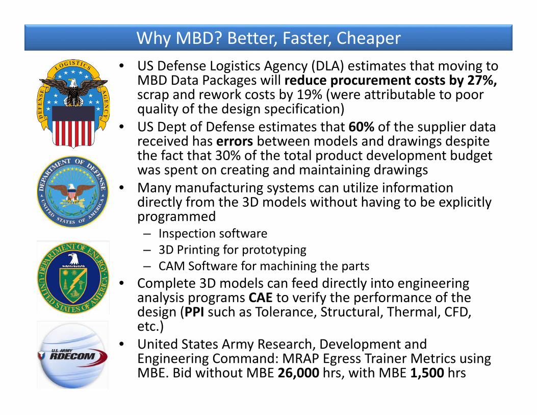
Why MBD? Better, Faster, Cheaper• US Defense Logistics Agency (DLA) estimates that moving to
MBD Data Packages will reduce procurement costs by 27%, scrap and rework costs by 19% (were attributable to poor quality of the design specification)
• US Dept of Defense estimates that 60% of the supplier data received has errors between models and drawings despite the fact that 30% of the total product development budget was spent on creating and maintaining drawings
• Many manufacturing systems can utilize information directly from the 3D models without having to be explicitly programmed– Inspection software– 3D Printing for prototyping– CAM Software for machining the parts
• Complete 3D models can feed directly into engineering analysis programs CAE to verify the performance of the design (PPI such as Tolerance, Structural, Thermal, CFD, etc.)
• United States Army Research, Development and Engineering Command: MRAP Egress Trainer Metrics using MBE. Bid without MBE 26,000 hrs, with MBE 1,500 hrs
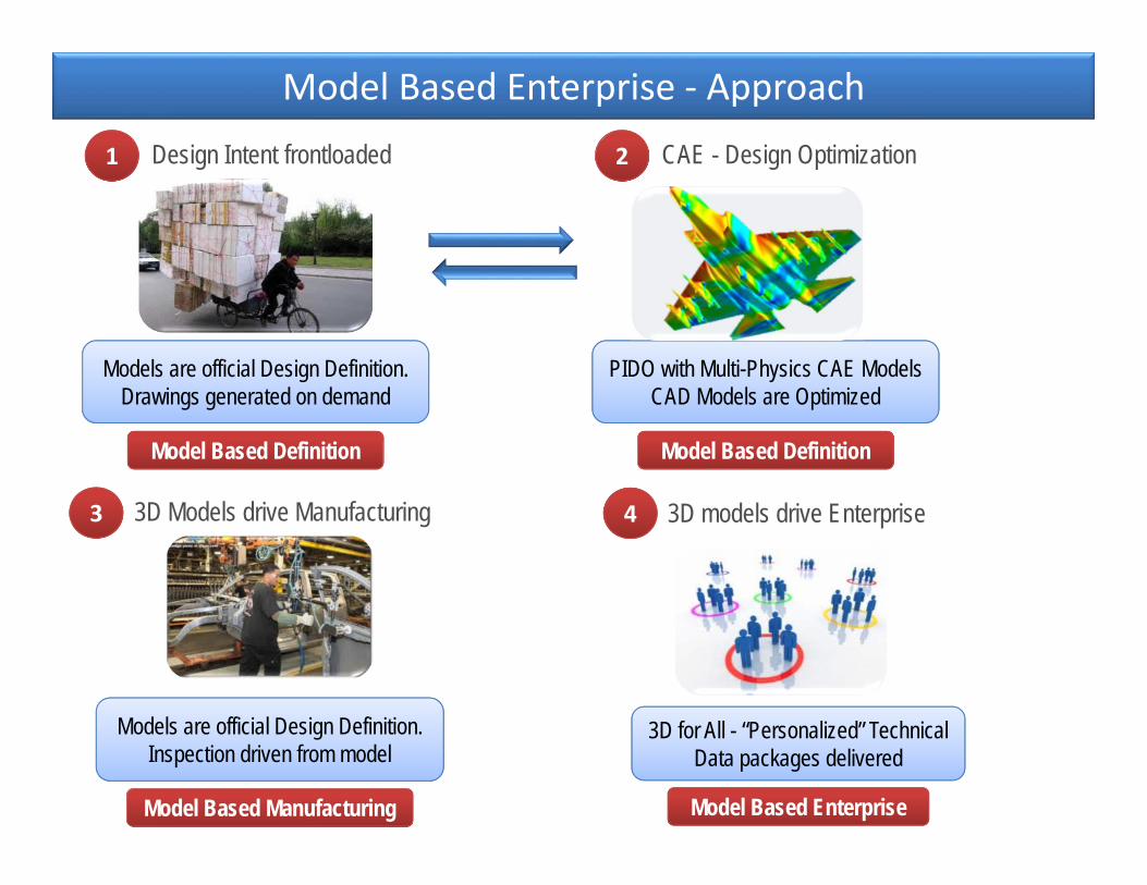
Model Based Enterprise ‐ Approach
1 Design Intent frontloaded
Models are official Design Definition. Drawings generated on demand
Model Based Definition
3D Models drive Manufacturing
Models are official Design Definition. Inspection driven from model
Model Based Manufacturing
3D models drive Enterprise
3D for All - “Personalized” Technical Data packages delivered
Model Based Enterprise
3 4
2 CAE - Design Optimization
PIDO with Multi-Physics CAE Models CAD Models are Optimized
Model Based Definition
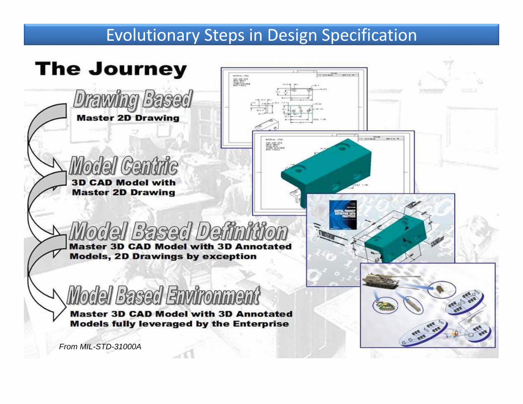
Evolutionary Steps in Design Specification
From MIL-STD-31000A
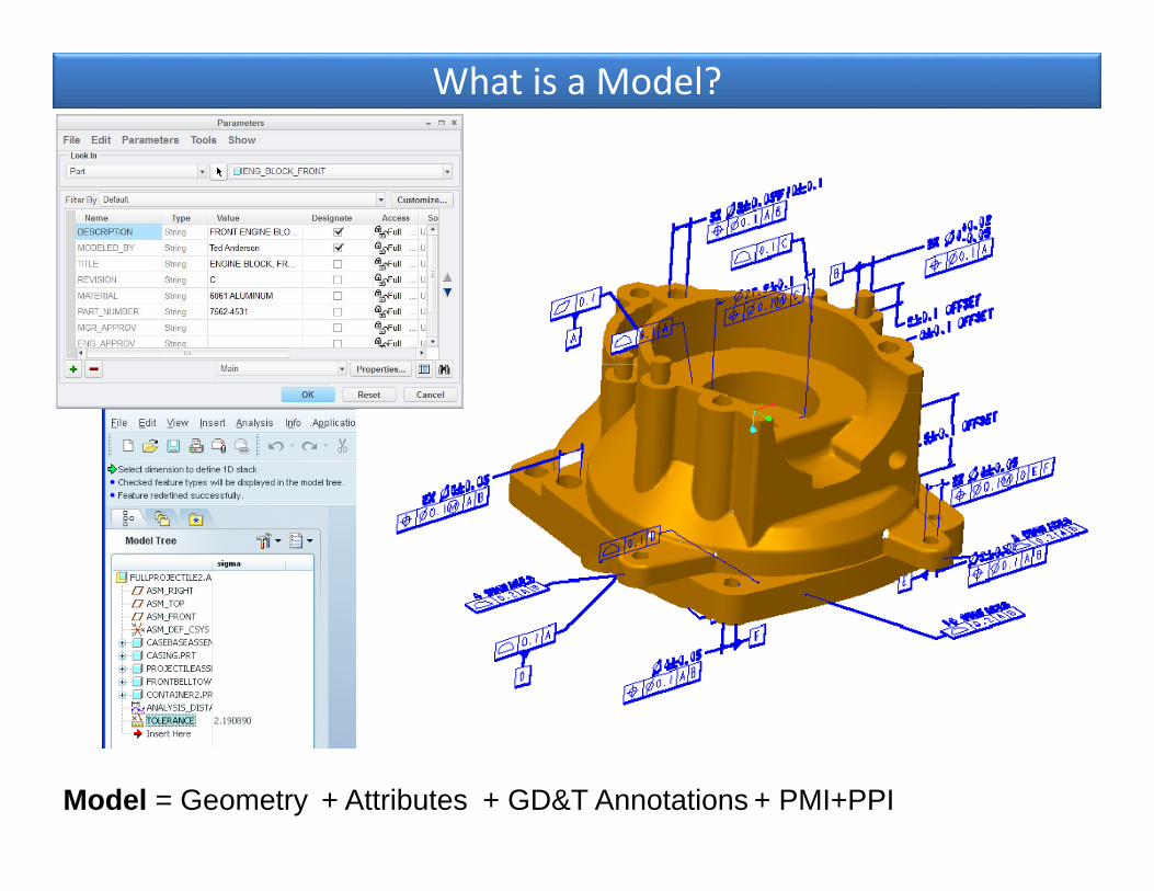
What is a Model?
Model = Geometry + Attributes + GD&T Annotations + PMI+PPI
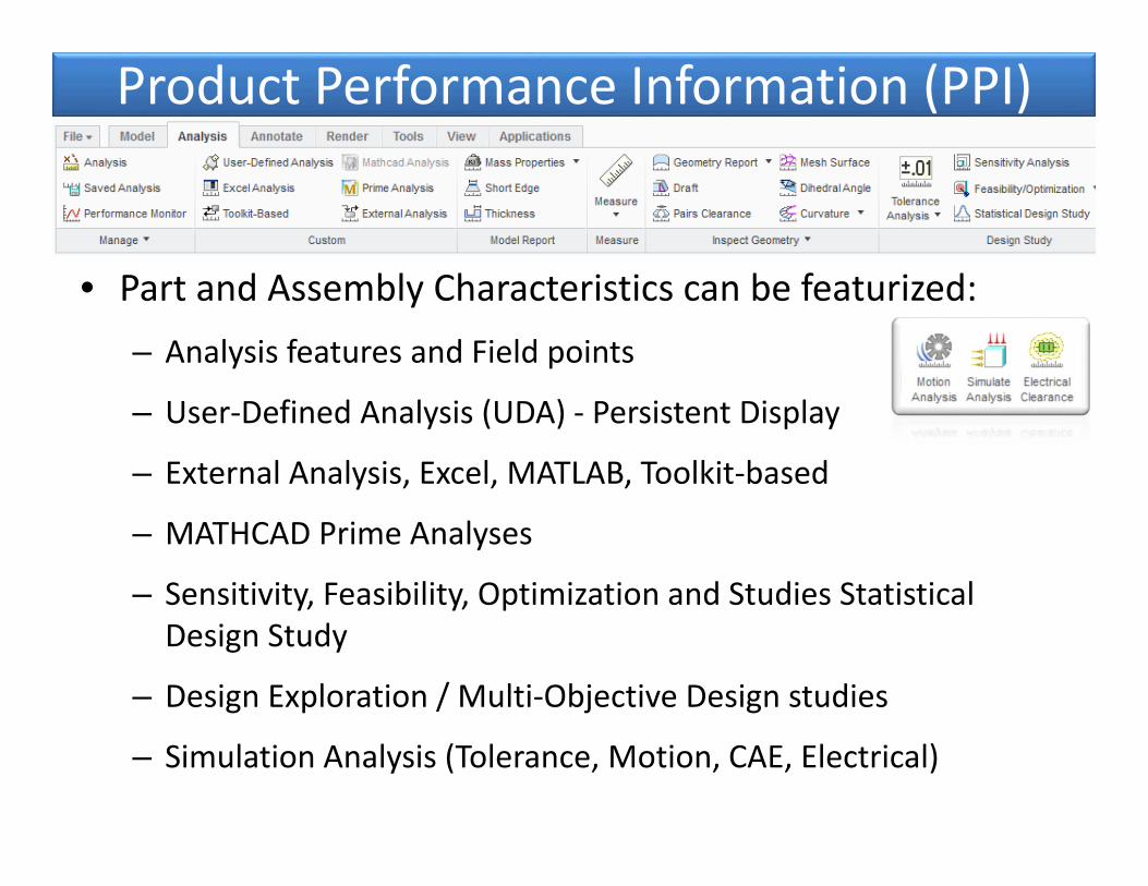
Product Performance Information (PPI)
• Part and Assembly Characteristics can be featurized:– Analysis features and Field points
– User‐Defined Analysis (UDA) ‐ Persistent Display
– External Analysis, Excel, MATLAB, Toolkit‐based
– MATHCAD Prime Analyses
– Sensitivity, Feasibility, Optimization and Studies Statistical Design Study
– Design Exploration / Multi‐Objective Design studies
– Simulation Analysis (Tolerance, Motion, CAE, Electrical)
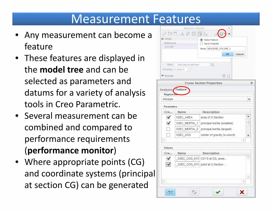
Measurement Features• Any measurement can become a feature
• These features are displayed in the model tree and can be selected as parameters and datums for a variety of analysis tools in Creo Parametric.
• Several measurement can be combined and compared to performance requirements (performance monitor)
• Where appropriate points (CG) and coordinate systems (principal at section CG) can be generated

PPI ‐ Simulation Features • Safety factors, Critical Buckling
values or Natural frequencies, drag coefficients, HIC are characteristics of the part/assemblies and its supports
• They can be associative to the part and update as dimensions or materials change
• They can appear in the model tree and part of MBD
• They can be used in the performance monitor for requirements management
• Mesh Controls, Load cases, Boundary conditions
• Surface and Volume Regions• Mid‐surfaces and welds
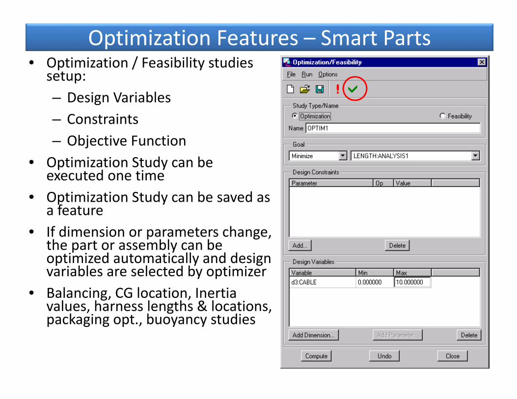
Optimization Features – Smart Parts• Optimization / Feasibility studies
setup:– Design Variables– Constraints– Objective Function
• Optimization Study can be executed one time
• Optimization Study can be saved as a feature
• If dimension or parameters change, the part or assembly can be optimized automatically and design variables are selected by optimizer
• Balancing, CG location, Inertia values, harness lengths & locations, packaging opt., buoyancy studies
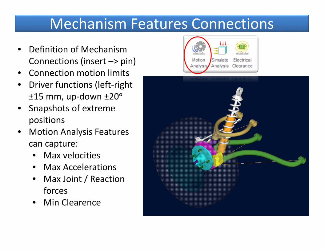
Mechanism Features Connections• Definition of Mechanism
Connections (insert –> pin)• Connection motion limits• Driver functions (left‐right
±15 mm, up‐down ±20ᵒ• Snapshots of extreme
positions• Motion Analysis Features
can capture:• Max velocities• Max Accelerations• Max Joint / Reaction
forces• Min Clearence
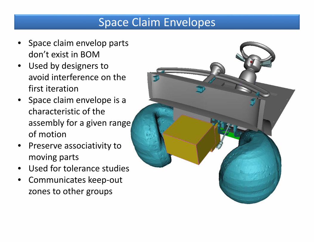
Space Claim Envelopes
• Space claim envelop parts don’t exist in BOM
• Used by designers to avoid interference on the first iteration
• Space claim envelope is a characteristic of the assembly for a given range of motion
• Preserve associativity to moving parts
• Used for tolerance studies• Communicates keep‐out
zones to other groups

Requirement Management with Performance Monitor Performance Monitor provides a summary of the values of the analyses features for immediate performance requirement status
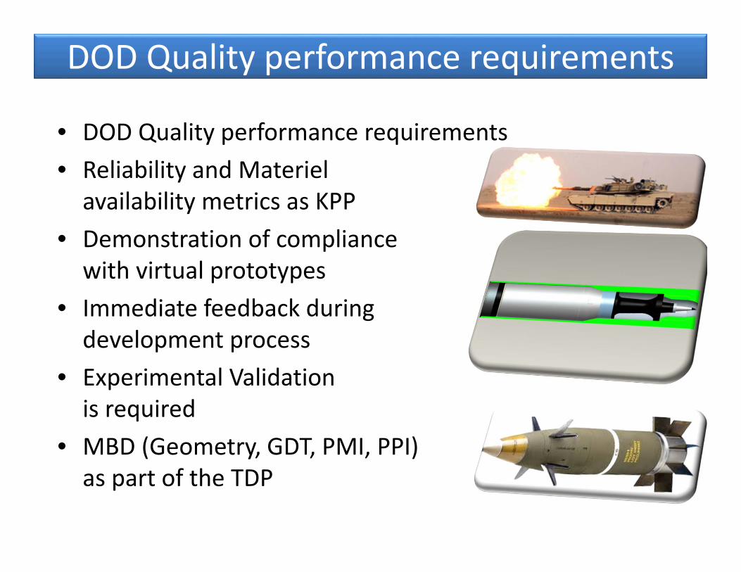
DOD Quality performance requirements
• DOD Quality performance requirements• Reliability and Materiel availability metrics as KPP
• Demonstration of compliance with virtual prototypes
• Immediate feedback duringdevelopment process
• Experimental Validation is required
• MBD (Geometry, GDT, PMI, PPI) as part of the TDP
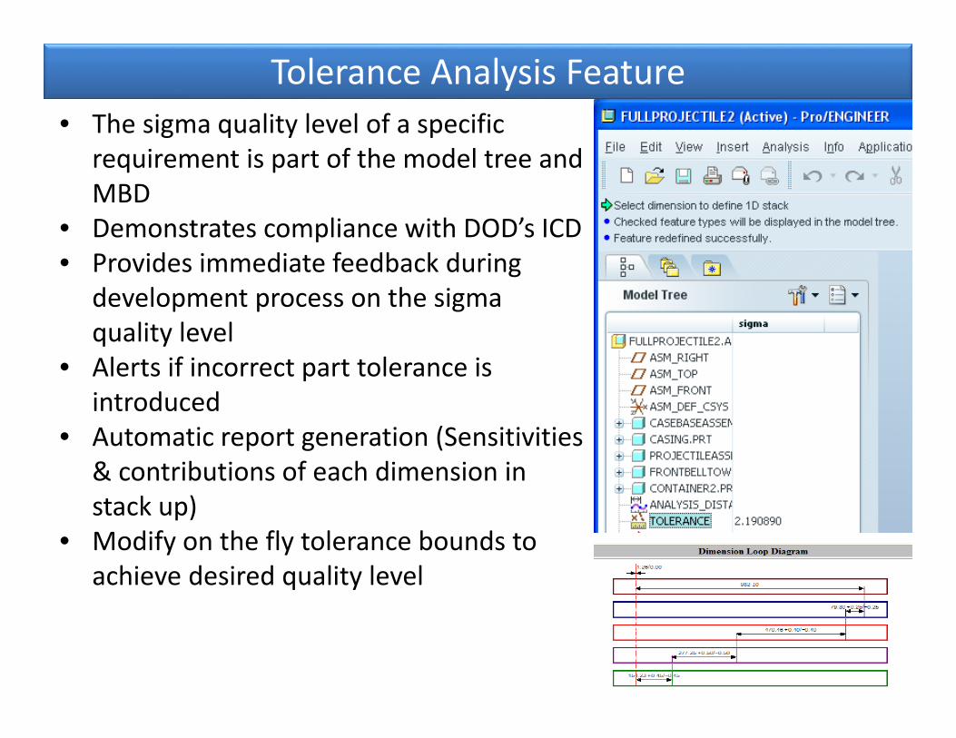
Tolerance Analysis Feature• The sigma quality level of a specific
requirement is part of the model tree and MBD
• Demonstrates compliance with DOD’s ICD• Provides immediate feedback during
development process on the sigma quality level
• Alerts if incorrect part tolerance is introduced
• Automatic report generation (Sensitivities & contributions of each dimension in stack up)
• Modify on the fly tolerance bounds to achieve desired quality level
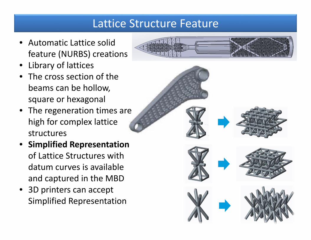
Lattice Structure Feature• Automatic Lattice solid feature (NURBS) creations
• Library of lattices• The cross section of the beams can be hollow, square or hexagonal
• The regeneration times are high for complex lattice structures
• Simplified Representation of Lattice Structures with datum curves is available and captured in the MBD
• 3D printers can accept Simplified Representation
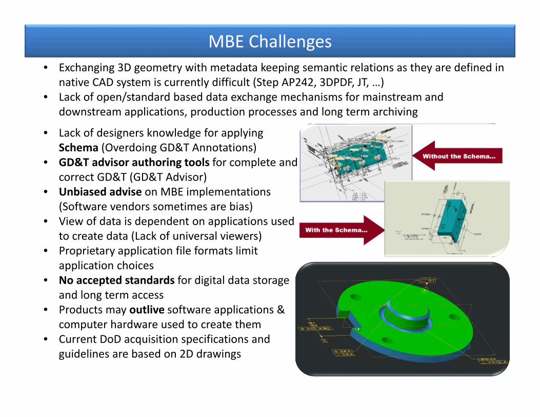
MBE Challenges
• Lack of designers knowledge for applying Schema (Overdoing GD&T Annotations)
• GD&T advisor authoring tools for complete and correct GD&T (GD&T Advisor)
• Unbiased advise on MBE implementations (Software vendors sometimes are bias)
• View of data is dependent on applications used to create data (Lack of universal viewers)
• Proprietary application file formats limit application choices
• No accepted standards for digital data storage and long term access
• Products may outlive software applications & computer hardware used to create them
• Current DoD acquisition specifications and guidelines are based on 2D drawings
• Exchanging 3D geometry with metadata keeping semantic relations as they are defined in native CAD system is currently difficult (Step AP242, 3DPDF, JT, …)
• Lack of open/standard based data exchange mechanisms for mainstream and downstream applications, production processes and long term archiving

Expected Benefits of MBE with PPI • Product Engineers working together with
Manufacturing Engineers create a 3D model with production process instructions
• Product characteristics PPI are linked to 3D models and extracted directly out of designs into conformance requirements
• Conformance requirements (QIF) are linked to manufacturing process and inspection instructions
• As‐built data is delivered by Production along with product to customer and is made available for sustainment services to continue evolving the products' data during operation and maintenance services
• Product design changes follow the same data flow and automatically update downstream models, references and instructions.